The RPM module will remain in Normal mode by default. It will also return to this mode after settings have been recalled or changed
|
|
|
- Isabel Stevenson
- 6 years ago
- Views:
Transcription
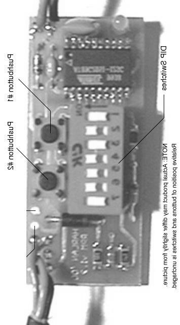
1 Shiftlight Operating Instructions: Setting up your shiftlight: The RPM module requires you to set the turn-on RPM and the number of cylinders. Once these two pieces of information are set, they will not need to be reset unless to a different value. However, if the settings are ever lost the light will notify you of the condition and you will need to reset both values. The RPM module will remain in Normal mode by default. It will also return to this mode after settings have been recalled or changed Programming the number of cylinders: 1) Refer to the attached chart for selecting the proper DIP switch setting for your application. 2) Ensure that the Shiftlight has power, i.e. turn the ignition key on. The engine does not need to be running. 3) Press and hold Pushbutton #1 (Refer to the picture) until the indicator begins to flash rapidly. Approximately two (2) seconds. 4) Release the button. 5) After a short pause, the indicator will flash the setting back to you. Note: In actuality, you are setting the number of pulses the module receives per revolution of the engine. Use this information to make your setting selection from the chart if your application is non-distributor. The indicator will flash the number of cylinders you have set. Count the flashes to double check the setting. If the reported setting does not match with what you tried to set, double check the DIP switch settings. It is easy to be between ON and OFF with the switches. Re-check and repeat the procedure. If an invalid setting is used, i.e. not in the chart, the indicator will flash the error flash. The indicator will flash six (6) times. The pattern is, two quick flashes followed by a pause, repeated three (3) times. Total of 6. For 2/4/6/8 cylinder settings, the indicator will flash 2/4/6/8. For Coil Per Plug setting, the indicator will flash once. Programming the RPM turn-on point: 1) Refer to the attached chart for selecting the proper DIP switch setting for your turn-on RPM. 2) Ensure that the Shiftlight has power, i.e. turn the ignition key on. The engine does not need to be running. 3) Press and hold Pushbutton #2 (Refer to the picture) until the indicator begins to flash rapidly. Approximately two (2) seconds. 4) Release the button. 5) After a short pause, the indicator will flash the setting back to you. Note: You are setting the turn-on RPM in 100 RPM increments. Thus, the indicator will flash the upper two digits of your setting back to you. There is a lower limit placed on the RPM which you can set, 500 RPM. A zero is displayed as two rapid flashes.
2 Examples: 1) If you want to set the turn-on point to be 5800 RPM, refer to the chart for the DIP switch settings for this RPM. Or, if you can do binary in your head, figure out the binary equivalent of 58 (5800 / 100) Follow the programming procedure above. After a pause, the indicator will begin flashing. It will flash five (5) times in a row, pause for about 1 second, then flash eight (8) times. Basically it is flashing 58 back to you.
3 Installation Instruction The wiring for the module is pretty straight forward. The minimum number of connections needed for operation is three (3) Exiting the back of the housing is a black cable containing three wires, Red, Black, and Green. Red Wire Connect this wire to a +12V source. The fuse block is a good choice for this connection, a switch accessory fuse is a prime choice. The will turn the module off when the key is off. But, any switched +12V source is ok. Black Wire This is the ground connection for the module. Chose a convenient ground location. A mounting screw or any other metal piece that makes a direct connection to the body will do. The radio ground is also a possibility. Green Wire This is the Tach input to the module. This can be either from the Tach line of the engine computer or from the switched side of an ignition coil. LS1 specific: The RED connector on the PCM is the one closest to the flat top/cover. The BLUE connector is closest to the bottom (not flat). 98 LS1: Tach line is Pin 35 on the BLUE connector. Tach line is a white wire LS1: Tach line is Pin 10 on the RED connector. Tach line is a white wire There are gray plastic covers on the connector. These will pop off. The wires are numbered under this gray cover. Pop the cover off, find the appropriate wire and splice into it. Run the wire into the vehicle and to your light. You can drive external Lights and other devices with the RPM module. A relay is required when this is done. A standard automotive relay will work. To drive other devices: 1) Remove the module from the housing. 2) Note two wires, Red and Black, connecting the light assembly to the RPM module. 3) You can cut/splice into the black wire to provide a switched ground to drive a relay. DO NOT try and directly ground external lights or solenoids with the module, you will fry it! Chose an appropriate mounting location for the module. The indicator is some what directional. It will appear brighter when aimed directly at you. Questions: turbohawk80@yahoo.com or harlan@sketchy.net Web:
4
5 SWITCH POSITIONS SWITCH POSITIONS RPM RPM ON OFF ON OFF OFF OFF OFF 6300 ON ON ON ON ON ON OFF 600 OFF ON ON OFF OFF OFF OFF 6400 OFF OFF OFF OFF OFF OFF ON 700 ON ON ON OFF OFF OFF OFF 6500 ON OFF OFF OFF OFF OFF ON 800 OFF OFF OFF ON OFF OFF OFF 6600 OFF ON OFF OFF OFF OFF ON 900 ON OFF OFF ON OFF OFF OFF 6700 ON ON OFF OFF OFF OFF ON 1000 OFF ON OFF ON OFF OFF OFF 6800 OFF OFF ON OFF OFF OFF ON 1100 ON ON OFF ON OFF OFF OFF 6900 ON OFF ON OFF OFF OFF ON 1200 OFF OFF ON ON OFF OFF OFF 7000 OFF ON ON OFF OFF OFF ON 1300 ON OFF ON ON OFF OFF OFF 7100 ON ON ON OFF OFF OFF ON 1400 OFF ON ON ON OFF OFF OFF 7200 OFF OFF OFF ON OFF OFF ON 1500 ON ON ON ON OFF OFF OFF 7300 ON OFF OFF ON OFF OFF ON 1600 OFF OFF OFF OFF ON OFF OFF 7400 OFF ON OFF ON OFF OFF ON 1700 ON OFF OFF OFF ON OFF OFF 7500 ON ON OFF ON OFF OFF ON 1800 OFF ON OFF OFF ON OFF OFF 7600 OFF OFF ON ON OFF OFF ON 1900 ON ON OFF OFF ON OFF OFF 7700 ON OFF ON ON OFF OFF ON 2000 OFF OFF ON OFF ON OFF OFF 7800 OFF ON ON ON OFF OFF ON 2100 ON OFF ON OFF ON OFF OFF 7900 ON ON ON ON OFF OFF ON 2200 OFF ON ON OFF ON OFF OFF 8000 OFF OFF OFF OFF ON OFF ON 2300 ON ON ON OFF ON OFF OFF 8100 ON OFF OFF OFF ON OFF ON 2400 OFF OFF OFF ON ON OFF OFF 8200 OFF ON OFF OFF ON OFF ON 2500 ON OFF OFF ON ON OFF OFF 8300 ON ON OFF OFF ON OFF ON 2600 OFF ON OFF ON ON OFF OFF 8400 OFF OFF ON OFF ON OFF ON 2700 ON ON OFF ON ON OFF OFF 8500 ON OFF ON OFF ON OFF ON 2800 OFF OFF ON ON ON OFF OFF 8600 OFF ON ON OFF ON OFF ON 2900 ON OFF ON ON ON OFF OFF 8700 ON ON ON OFF ON OFF ON 3000 OFF ON ON ON ON OFF OFF 8800 OFF OFF OFF ON ON OFF ON 3100 ON ON ON ON ON OFF OFF 8900 ON OFF OFF ON ON OFF ON 3200 OFF OFF OFF OFF OFF ON OFF 9000 OFF ON OFF ON ON OFF ON 3300 ON OFF OFF OFF OFF ON OFF 9100 ON ON OFF ON ON OFF ON 3400 OFF ON OFF OFF OFF ON OFF 9200 OFF OFF ON ON ON OFF ON 3500 ON ON OFF OFF OFF ON OFF 9300 ON OFF ON ON ON OFF ON 3600 OFF OFF ON OFF OFF ON OFF 9400 OFF ON ON ON ON OFF ON 3700 ON OFF ON OFF OFF ON OFF 9500 ON ON ON ON ON OFF ON 3800 OFF ON ON OFF OFF ON OFF 9600 OFF OFF OFF OFF OFF ON ON 3900 ON ON ON OFF OFF ON OFF 9700 ON OFF OFF OFF OFF ON ON 4000 OFF OFF OFF ON OFF ON OFF 9800 OFF ON OFF OFF OFF ON ON 4100 ON OFF OFF ON OFF ON OFF 9900 ON ON OFF OFF OFF ON ON 4200 OFF ON OFF ON OFF ON OFF OFF OFF ON OFF OFF ON ON 4300 ON ON OFF ON OFF ON OFF ON OFF ON OFF OFF ON ON 4400 OFF OFF ON ON OFF ON OFF OFF ON ON OFF OFF ON ON 4500 ON OFF ON ON OFF ON OFF ON ON ON OFF OFF ON ON 4600 OFF ON ON ON OFF ON OFF OFF OFF OFF ON OFF ON ON 4700 ON ON ON ON OFF ON OFF ON OFF OFF ON OFF ON ON 4800 OFF OFF OFF OFF ON ON OFF OFF ON OFF ON OFF ON ON 4900 ON OFF OFF OFF ON ON OFF ON ON OFF ON OFF ON ON 5000 OFF ON OFF OFF ON ON OFF OFF OFF ON ON OFF ON ON 5100 ON ON OFF OFF ON ON OFF ON OFF ON ON OFF ON ON 5200 OFF OFF ON OFF ON ON OFF OFF ON ON ON OFF ON ON 5300 ON OFF ON OFF ON ON OFF ON ON ON ON OFF ON ON 5400 OFF ON ON OFF ON ON OFF OFF OFF OFF OFF ON ON ON 5500 ON ON ON OFF ON ON OFF ON OFF OFF OFF ON ON ON 5600 OFF OFF OFF ON ON ON OFF OFF ON OFF OFF ON ON ON 5700 ON OFF OFF ON ON ON OFF ON ON OFF OFF ON ON ON 5800 OFF ON OFF ON ON ON OFF OFF OFF ON OFF ON ON ON 5900 ON ON OFF ON ON ON OFF ON OFF ON OFF ON ON ON 6000 OFF OFF ON ON ON ON OFF OFF ON ON OFF ON ON ON 6100 ON OFF ON ON ON ON OFF ON ON ON OFF ON ON ON 6200 OFF ON ON ON ON ON OFF OFF OFF OFF ON ON ON ON
6 SWITCH POSITIONS # Cylinders ON OFF OFF OFF OFF OFF OFF 4 OFF ON OFF OFF OFF OFF OFF 6 OFF OFF ON OFF OFF OFF OFF 8 OFF OFF OFF ON OFF OFF OFF Coil Per Plug OFF OFF OFF OFF ON OFF OFF NOTE: LS1 uses 4 cylinder mode
Installation Instructions for Lingenfelter Shift Light Controller with green LED
 Installation Instructions for Lingenfelter Shift Light Controller with green LED PN: L460080000 1557 Winchester Road Decatur, Indiana 46733 260 724 2552 phone 260 724 8761 fax www.lingenfelter.com Parts
CONTROL BOX. Wiring the control box into the vehicle. +12V
 CONTROL BOX Once the display panel is in place, mount the control box within the connecting cable's distance (approximately 3 feet) and secure to the underside of the dashboard. This case does not have
PRODUCT GUIDE HCF900A DOCUMENT NUMBER REVISION DATE
 PRODUCT GUIDE DOCUMENT NUMBER REVISION DATE 20161024 NOTICE The manufacturer will accept no responsability for any electrical damage resulting from improper installation of this product, be that either
Product Overview. Shift light turns on when RPM is above programmed shift point. Stage 2 activation light turns on when Stage 2 is active.
 These instructions will guide you through the setup, installation, and use of the Nitrous Outlet WinMax Window Switch. If you have any questions about the WinMax, please call our Tech Help Line at (254)
# Traction Control Window Switch
 1 INSTRUCTIONS # 82085 Traction Control Window Switch Thank you for choosing products; we are proud to be your manufacturer of choice. Please read this instruction sheet carefully before beginning installation,
INSTALLATION GUIDE Six Gauge Universal Digital Dash Panel Part Number: DP10002
 Made in America Lifetime Guarantee Thank you for purchasing this digital dash panel from Intellitronix. We value our customers! INSTALLATION GUIDE Six Gauge Universal Digital Dash Panel Part Number: DP10002
ION-01-6 PERFORMANCE SPEEDOMETER/TACHOMETER COMBO
 ION-01-6 PERFORMANCE SPEEDOMETER/TACHOMETER COMBO MOUNTING: It should be inserted into the opening from the front and the L-clamps will be installed from the back. Tighten the nuts on the L-clamps so that
ECT Display Driver Installation for AP2 Module
 ECT Display Driver Installation for AP2 Module Overview The ECT Display Driver is a small module with a removable wire harness that mounts behind the driver's foot well cover. All wiring connections are
PRODUCT GUIDE FT-DC2-S DOCUMENT NUMBER REVISION DATE
 PRODUCT GUIDE DOCUMENT NUMBER REVISION DATE 20161025 NOTICE The manufacturer will accept no responsability for any electrical damage resulting from improper installation of this product, be that either
FULL SWEEP STEPPER MOTOR INSTRUMENT KIT INSTRUCTION MANUAL 1969,REDLINE, 2020 SERIES
 FULL SWEEP STEPPER MOTOR INSTRUMENT KIT INSTRUCTION MANUAL 1969,REDLINE, 2020 SERIES REVB071211 INDEX 3-3/8 PROGRAMMABLE SPEEDOMETER 3-3/8 TACHOMETER 2-1/16 GAUGES TEMPERATRURE SENDER PRESSURE SENDER PROGRAMMABLE
PRODUCT GUIDE CMVWXA0
 PRODUCT GUIDE DOCUMENT NUMBER REVISION DATE 20181116 NOTICE The manufacturer will accept no responsability for any electrical damage resulting from improper installation of this product, be that either
INSTALL GUIDE OL-HA(RS)-HA6P-[OL-RS-HA6]-EN
![INSTALL GUIDE OL-HA(RS)-HA6P-[OL-RS-HA6]-EN](/thumbs/80/82109789.jpg "INSTALL GUIDE OL-HA(RS)-HA6P-[OL-RS-HA6]-EN") INSTALL GUIDE DOCUMENT NUMBER 5699 REVISION DATE 7 FIRMWARE OL-HA(RS)-HA6P-[OL-RS-HA6] HARDWARE OL-RS-HA6 ACCESSORIES OL-LOADER (REQUIRED) RF-0/0/50-EDP (OPTIONAL) LINKR (OPTIONAL) NOTICE The manufacturer
INSTALL GUIDE DOCUMENT NUMBER 5699 REVISION DATE 7 FIRMWARE OL-HA(RS)-HA6P-[OL-RS-HA6] HARDWARE OL-RS-HA6 ACCESSORIES OL-LOADER (REQUIRED) RF-0/0/50-EDP (OPTIONAL) LINKR (OPTIONAL) NOTICE The manufacturer
install guide OEM-IDS(RS)-BM1-[ADS-BM1]-EN
![install guide OEM-IDS(RS)-BM1-[ADS-BM1]-EN](/thumbs/78/76901805.jpg "install guide OEM-IDS(RS)-BM1-[ADS-BM1]-EN") install guide Document number 9 Revision Date 50 firmware OEM-IDS(RS)-BM-[ADS-BM] hardware ADS-BM accessories ADS-USB (REQUIRED) NOTICE The manufacturer will accept no responsability for any electrical
install guide Document number 9 Revision Date 50 firmware OEM-IDS(RS)-BM-[ADS-BM] hardware ADS-BM accessories ADS-USB (REQUIRED) NOTICE The manufacturer will accept no responsability for any electrical
MEGA 462 REMOTE CONTROL AUTO ALARM SYSTEM INSTALLATION & OPERATION INSTRUCTIONS WIRING DIAGRAM. White. H1 5 Pin White. H6 2 Pin White.
 MEGA 462 REMOTE CONTROL AUTO ALARM SYSTEM INSTALLATION & OPERATION INSTRUCTIONS WIRING DIAGRAM H7/1 Green : (-) 200mA Pulse H7 3 Pin H7/3 Blue : (-) 200mA Unlock White LED Indicator Valet Switch H6 2 Pin
12V PROGRAMMABLE POWER OUT
 Page 1 ACCESSORIES STARTER IGNITION BATTERY WIRES SIDE VIEW BLUE RED YELLOW 30 A 10 A BLUE / WHITE YELLOW WHITE / BLUE WHITE / DOOR TRIGGER See opt. 16 DOOR TRIGGER (input positive) See opt. 16 PARKING
INSTALLATION GUIDE Table of Contents
 CT-3100 Automatic transmission remote engine starter systems. What s included..2 INSTALLATION GUIDE Table of Contents Door lock toggle mode..... 4 Notice...2 Installation points to remember. 2 Features..2
PRODUCT GUIDE VWX000A DOCUMENT NUMBER REVISION DATE
 PRODUCT GUIDE DOCUMENT NUMBER REVISION DATE 20161107 NOTICE The manufacturer will accept no responsability for any electrical damage resulting from improper installation of this product, be that either
INSTALL GUIDE IDL-HA(RS)-HA7-[ADS-HA7]-EN
![INSTALL GUIDE IDL-HA(RS)-HA7-[ADS-HA7]-EN](/thumbs/78/77544933.jpg "INSTALL GUIDE IDL-HA(RS)-HA7-[ADS-HA7]-EN") INSTALL GUIDE DOCUMENT NUMBER 090 REVISION DATE 7070 FIRMWARE IDL-HA(RS)-HA7-[ADS-HA7] HARDWARE ADS-HA7 ACCESSORIES ADS-USB (REQUIRED) COMPATIBLE RF-KIT (REQUIRED) DIRECTED SMARTSTART & ADS-HRN(RS)-SM
INSTALL GUIDE DOCUMENT NUMBER 090 REVISION DATE 7070 FIRMWARE IDL-HA(RS)-HA7-[ADS-HA7] HARDWARE ADS-HA7 ACCESSORIES ADS-USB (REQUIRED) COMPATIBLE RF-KIT (REQUIRED) DIRECTED SMARTSTART & ADS-HRN(RS)-SM
Tachometers and Tach/Hourmeters
 Tachometers and Tach/Hourmeters AT and ATH Series Installation Instructions IMPORTANT! These instructions are specific to tachometer models with a power input operating range of 11-28 VDC and calibration
PRODUCT GUIDE OL-RS-VW1 DOCUMENT NUMBER REVISION DATE
 PRODUCT GUIDE DOCUMENT NUMBER REVISION DATE 20180116 NOTICE The manufacturer will accept no responsability for any electrical damage resulting from improper installation of this product, be that either
install guide COM-IDS(RS)-BM1-[ADS-BM1]-EN
![install guide COM-IDS(RS)-BM1-[ADS-BM1]-EN](/thumbs/78/77916996.jpg "install guide COM-IDS(RS)-BM1-[ADS-BM1]-EN") install guide Document number Revision Date 50 firmware COM-IDS(RS)-BM-[ADS-BM] hardware ADS-BM accessories ADS-USB (REQUIRED) COMPATIBLE RF-KIT (OPTIONAL) DRONE MOBILE DR-000 (OPTIONAL) NOTICE The manufacturer
install guide Document number Revision Date 50 firmware COM-IDS(RS)-BM-[ADS-BM] hardware ADS-BM accessories ADS-USB (REQUIRED) COMPATIBLE RF-KIT (OPTIONAL) DRONE MOBILE DR-000 (OPTIONAL) NOTICE The manufacturer
INSTALLATION GUIDE Chevrolet Monte Carlo Dash Panel Part Number: DP9002 Year Series:
 Made in America Lifetime Guarantee Thank you for purchasing this instrument from Intellitronix. We value our customers! INSTALLATION GUIDE Chevrolet Monte Carlo Dash Panel Part Number: DP9002 Year Series:
INSTALL GUIDE COM-HA(RS)-HA6P-[FT-HA6-DC]-EN
![INSTALL GUIDE COM-HA(RS)-HA6P-[FT-HA6-DC]-EN](/thumbs/91/107082835.jpg "INSTALL GUIDE COM-HA(RS)-HA6P-[FT-HA6-DC]-EN") INSTALL GUIDE DOCUMENT NUMBER 49378 REVISION DATE 20180412 FIRMWARE COM-HA(RS)-HA6P-[FT-HA6-DC] HARDWARE FT-HA6-DC ACCESSORIES ADS-USB (REQUIRED) COMPATIBLE RF-KIT (OPTIONAL) DRONE MOBILE DR-2000 (OPTIONAL)
INSTALL GUIDE DOCUMENT NUMBER 49378 REVISION DATE 20180412 FIRMWARE COM-HA(RS)-HA6P-[FT-HA6-DC] HARDWARE FT-HA6-DC ACCESSORIES ADS-USB (REQUIRED) COMPATIBLE RF-KIT (OPTIONAL) DRONE MOBILE DR-2000 (OPTIONAL)
Tachometers and Tach/Hourmeters
 Tachometers and Tach/Hourmeters AT and ATH Series Installation Instructions IMPORTANT! These instructions are specific to tachometer models with a power input operating range of 11-28 VDC and calibration
Thank you for purchasing this instrument from Intellitronix. We value our customers!
 Made in America Lifetime Guarantee Thank you for purchasing this instrument from Intellitronix. We value our customers! INSTALLATION GUIDE Corvette Digital Dash Panel Part Number: DP2003 Year Series: 1984-1989
Service Manual for Battery Control Center
 Service Manual for Battery Control Center P/N 82 E0071 00 (Ref. 81 1317) June, 1999 Battery Control Box Operation Charging Circuit This function charges the coach battery from the engine alternator while
Volkswagen B3 Passat Diagnosis, Fault Memory - Passat Diagnosis, Fault Memory (Page GR-D4)
") Diagnosis, Fault Memory (Page GR-D4) Anti-lock brake system (ABS) electrical testing self-diagnosis troubleshooting using electrical steps VAG 1551 Diagnostic Tester connecting erasing Fault memory reading
Diagnosis, Fault Memory (Page GR-D4) Anti-lock brake system (ABS) electrical testing self-diagnosis troubleshooting using electrical steps VAG 1551 Diagnostic Tester connecting erasing Fault memory reading
G - TESTS W/CODES - 2.2L
 G - TESTS W/CODES - 2.2L 1994 Toyota Celica 1994 ENGINE PERFORMANCE Toyota 2.2L Self-Diagnostics Celica INTRODUCTION If no faults were found while performing F - BASIC TESTING, proceed with self-diagnostics.
INSTALL GUIDE FLC-HA(RS)-HA6P-[FLRSHA6]-EN
![INSTALL GUIDE FLC-HA(RS)-HA6P-[FLRSHA6]-EN](/thumbs/83/88785406.jpg "INSTALL GUIDE FLC-HA(RS)-HA6P-[FLRSHA6]-EN") INSTALL GUIDE DOCUMENT NUMBER 49388 REVISION DATE 20180412 FIRMWARE FLC-HA(RS)-HA6P-[FLRSHA6] HARDWARE FLRSHA6 ACCESSORIES FLPROG (REQUIRED) FLRF1/2/4 (OPTIONAL) CARLINK ASCL2 (OPTIONAL) TERMS OF USE:
INSTALL GUIDE DOCUMENT NUMBER 49388 REVISION DATE 20180412 FIRMWARE FLC-HA(RS)-HA6P-[FLRSHA6] HARDWARE FLRSHA6 ACCESSORIES FLPROG (REQUIRED) FLRF1/2/4 (OPTIONAL) CARLINK ASCL2 (OPTIONAL) TERMS OF USE:
INSTALLATION GUIDE Chevrolet Impala/Caprice Digital Dash Panel Part Number: DP1208 Year Series: 1968
 Made in America Lifetime Guarantee Thank you for purchasing this instrument from Intellitronix. We value our customers! INSTALLATION GUIDE Chevrolet Impala/Caprice Digital Dash Panel Part Number: DP1208
Model AX-510 Owner s Manual
 Model AX-510 Owner s Manual 4 Button Remote Security System with Dual Stage Shock Sensor IMPORTANT! In order to provide the highest possible level of security to your vehicle, this system is equipped with
Typical applications are the control of barriers/booms in the parking and access control environments.
 Barrier Logic Model - BL110B The BL110B is a barrier logic unit which has been developed to control barriers using magnetic motors with ease of installation. The BL110B accepts inputs from card readers
PRO-COMP/PHANTOM TACH
 2650-895B INSTALLATION INSTRUCTIONS 5 single channel PRO-COMP/PHANTOM TACH COPYRIGHT PATENT 5 4 6 3 PENDING 7 8 PLAYBACK 9 2 0 1 AUTO METER PRODUCTS, INC. SYCAMORE, IL USA MADE RPM x 1000 IN USA MENU SELECT
INSTALL GUIDE OEM-GM(RS)-GM2-[ADS-GM2]-EN
![INSTALL GUIDE OEM-GM(RS)-GM2-[ADS-GM2]-EN](/thumbs/92/109129040.jpg "INSTALL GUIDE OEM-GM(RS)-GM2-[ADS-GM2]-EN") INSTALL GUIDE DOCUMENT NUMBER 0 REVISION DATE FIRMWARE OEM-GM(RS)-GM-[ADS-GM] HARDWARE ADS-GM ACCESSORIES ADS-USB (REQUIRED) NOTICE The manufacturer will accept no responsability for any electrical damage
INSTALL GUIDE DOCUMENT NUMBER 0 REVISION DATE FIRMWARE OEM-GM(RS)-GM-[ADS-GM] HARDWARE ADS-GM ACCESSORIES ADS-USB (REQUIRED) NOTICE The manufacturer will accept no responsability for any electrical damage
VSM V-COUNT II are registered trademark of APEXS, Inc.
 Applied Expert Systems Inc. (APEXS, Inc.). 2003.All rights reserved VSM V-COUNT Vehicle Speed Sensor (VSS) Installation Guide VSM V-COUNT II are registered trademark of APEXS, Inc. VSS Installation Guide
HDMD-200/300 Universal display
 Universal display I n s ta l l at i o n G u i d e Micro Display Kit 9 Mendenhall Drive North Las Vegas, NV 8908 www.dynojet.com -800-99-4993 www.dynojet.com Display unit Attachment Pegs Cable Harness Hex
TWO-WAY LED AUTOMATIC TRANSMISSION REMOTE STARTER. User Guide WARNING
 TWO-WAY LED AUTOMATIC TRANSMISSION REMOTE STARTER User Guide WARNING It is the responsibility of the vehicle operator to ensure their vehicle is parked in a safe and responsible manner. 1. When leaving
MSD Programmable Shift Controller PN 75591
 MSD Programmable Shift Controller PN 75591 WARNING: During installation, disconnect the battery cables. When disconnecting, always remove the Negative cable first and install it last. Parts Included: 1
Crankshaft Position Sensor
 1 of 7 1 GM Bonneville/Eighty Eight/LeSabre 1986-1999 Crankshaft Position Sensor OPERATION TESTING REMOVAL & INSTALLATION See Figures 1, 2 and 3 The dual Crankshaft Position (CKP) sensor is mounted to
BSR Magic Box Digital ignition control for 4, 6, or 8 cylinder engines
 BSR BSR Magic Box Digital ignition control for 4, 6, or 8 cylinder engines Features Digital Advance The main feature of the Magic Box is the digital advance that replaces conventional weights and springs.
INSTALLATION INSTRUCTIONS 5" SINGLE CHANNEL ULTIMATE TACH
 Instr. No. 2650-887D INSTALLATION INSTRUCTIONS 5" SINGLE CHANNEL ULTIMATE TACH IMPORTANT WEAR SAFETY GLASSES 5 4 6 COPYRIGHT PATENT PENDING 3 7 8 PLAYBACK 9 2 0 1 AUTO METER PRODUCTS, INC. SYCAMORE, IL
Alarms & Remote Start
 Alarms & Remote Start INSTALL GUIDE DOCUMENT NUMBER 5866 REVISION DATE 0607 FIRMWARE OEM-IDS(RS)-BM-[OL-RS-BM] HARDWARE OL-RS-BM ACCESSORIES OL-LOADER (REQUIRED) NOTICE The manufacturer will accept no
NEXUS. Introduction SENSOR MODULE &
 2650-1056 INSTALLA AT TION INSTRUCTIONS NEXUS SENSOR MODULE & REMOTE ASSEMBLY IMPORTANT WEAR SAFETY GLASSES 60 80 40 100 FUEL 20 PSI 0 AUTO METER PRODUCTS INC. c 2004-6463 0 10 20 10 20 BOOST VAC In.Hg
INSTALL GUIDE IDL-IDS(RS)-BZ2B-[ADS-BZ2]-EN
![INSTALL GUIDE IDL-IDS(RS)-BZ2B-[ADS-BZ2]-EN](/thumbs/94/120297305.jpg "INSTALL GUIDE IDL-IDS(RS)-BZ2B-[ADS-BZ2]-EN") INSTALL GUIDE DOCUMENT NUMBER 450 REVISION DATE FIRMWARE IDL-IDS(RS)-BZB-[ADS-BZ] HARDWARE ADS-BZ ESSORIES ADS-USB (REQUIRED) COMPATIBLE RF-KIT (OPTIONAL) DIRECTED SMART & ADS-HRN(RS)-SM0 (OPTIONAL) ADS-TOOLS-MB0
INSTALL GUIDE DOCUMENT NUMBER 450 REVISION DATE FIRMWARE IDL-IDS(RS)-BZB-[ADS-BZ] HARDWARE ADS-BZ ESSORIES ADS-USB (REQUIRED) COMPATIBLE RF-KIT (OPTIONAL) DIRECTED SMART & ADS-HRN(RS)-SM0 (OPTIONAL) ADS-TOOLS-MB0
SmartPak Welding Controller WK-MPS-16 Constant Current
 SmartPak Welding Controller WK-MPS-16 Constant Current Features Latest state of the art ATMEL 8 bit microprocessor technology Synchronous digital welding control allows absolute precision Up to16 programmers
INSTALL GUIDE AKX-IDS(RS)-BZ1B-[ADS-BZ1]-EN
![INSTALL GUIDE AKX-IDS(RS)-BZ1B-[ADS-BZ1]-EN](/thumbs/77/75040905.jpg "INSTALL GUIDE AKX-IDS(RS)-BZ1B-[ADS-BZ1]-EN") INSTALL GUIDE DOCUMENT NUMBER 25893 REVISION DATE 2627 FIRMWARE AKX-IDS(RS)-BZ1B-[ADS-BZ1] HARDWARE ADS-BZ1 ESSORIES ADS-USB (REQUIRED) COMPATIBLE RF-KIT (OPTIONAL) DIRECTED SMART & ADS-HRN(RS)-SM (OPTIONAL)
INSTALL GUIDE DOCUMENT NUMBER 25893 REVISION DATE 2627 FIRMWARE AKX-IDS(RS)-BZ1B-[ADS-BZ1] HARDWARE ADS-BZ1 ESSORIES ADS-USB (REQUIRED) COMPATIBLE RF-KIT (OPTIONAL) DIRECTED SMART & ADS-HRN(RS)-SM (OPTIONAL)
OPERATING INSTRUCTIONS
 EZ-1 ONE BUTTON REMOTE START SYSTEM OPERATING INSTRUCTIONS CONGRATULATIONS on your choice of a Cool Start Remote Engine Starter and Keyless Entry with DP Technology by Crimestopper Security Products Inc.
install guide OEM-IDS(RS)-BM1-[ADS-BM1]-EN
![install guide OEM-IDS(RS)-BM1-[ADS-BM1]-EN](/thumbs/89/99397338.jpg "install guide OEM-IDS(RS)-BM1-[ADS-BM1]-EN") install guide Document number 13171 Revision Date 231121 firmware OEM-IDS(RS)-BM1-[ADS-BM1] hardware ADS-BM1 accessories ADS-USB (REQUIRED) NOTICE The manufacturer will accept no responsability for any
install guide Document number 13171 Revision Date 231121 firmware OEM-IDS(RS)-BM1-[ADS-BM1] hardware ADS-BM1 accessories ADS-USB (REQUIRED) NOTICE The manufacturer will accept no responsability for any
INSTALL GUIDE FLC-NI(RS)-NI6-[FLRSNI5]-EN
![INSTALL GUIDE FLC-NI(RS)-NI6-[FLRSNI5]-EN](/thumbs/93/112254470.jpg "INSTALL GUIDE FLC-NI(RS)-NI6-[FLRSNI5]-EN") INSTALL GUIDE FLC-NI(RS)-NI-[FLRSNI]-EN DOCUMENT NUMBER REVISION DE 000 FIRMWARE FLC-NI(RS)-NI-[FLRSNI] HARDWARE FLRSNI ACCESSORIES FLPROG (REQUIRED) FLRF// (OPTIONAL) CARLINK ASCL (OPTIONAL) NOTICE The
INSTALL GUIDE FLC-NI(RS)-NI-[FLRSNI]-EN DOCUMENT NUMBER REVISION DE 000 FIRMWARE FLC-NI(RS)-NI-[FLRSNI] HARDWARE FLRSNI ACCESSORIES FLPROG (REQUIRED) FLRF// (OPTIONAL) CARLINK ASCL (OPTIONAL) NOTICE The
INSTALL GUIDE OL-NI(RS)-NI5-[OL-RS-NI5]-EN
![INSTALL GUIDE OL-NI(RS)-NI5-[OL-RS-NI5]-EN](/thumbs/92/109538642.jpg "INSTALL GUIDE OL-NI(RS)-NI5-[OL-RS-NI5]-EN") INSTALL GUIDE DOCUMENT NUMBER 54560 REVISION DE 201818 FIRMWARE OL-NI(RS)-NI5-[OL-RS-NI5] HARDWARE OL-RS-NI5 ACCESSORIES OL-LOADER (REQUIRED) RF-10/30/50-EDP (OPTIONAL) LINKR (OPTIONAL) TERMS OF USE: Automotive
INSTALL GUIDE DOCUMENT NUMBER 54560 REVISION DE 201818 FIRMWARE OL-NI(RS)-NI5-[OL-RS-NI5] HARDWARE OL-RS-NI5 ACCESSORIES OL-LOADER (REQUIRED) RF-10/30/50-EDP (OPTIONAL) LINKR (OPTIONAL) TERMS OF USE: Automotive
TachMatch Instructions
 TachMatch Instructions Thank you for your purchase of the TachMatch Model TM01 from TechnoVersions LLC. The TachMatch has been designed to: accept various tachometer input signals (e.g., coil, MSD, HEI),
CS-2001 REMOTE CONTROL ALARM SYSTEM INSTALLATION & OPERATING INSTRUCTIONS INTRODUCTION
 CS-2001 REMOTE CONTROL ALARM SYSTEM INSTALLATION & OPERATING INSTRUCTIONS INTRODUCTION CONGRATULATIONS on your choice of a Gargoyle Remote Alarm System by Crimestopper Security Products Inc. This booklet
INSTALL GUIDE OEM-CH(RS)-CH4-[ADS-CH4]-EN
![INSTALL GUIDE OEM-CH(RS)-CH4-[ADS-CH4]-EN](/thumbs/93/114154959.jpg "INSTALL GUIDE OEM-CH(RS)-CH4-[ADS-CH4]-EN") INSTALL GUIDE DOCUMENT NUMBER 864 REVISI DATE 77 FIRMWARE OEM-CH(RS)-CH4-[ADS-CH4] HARDWARE ADS-CH4 ACCESSORIES ADS-USB (REQUIRED) NOTICE The manufacturer will accept no responsability for any electrical
INSTALL GUIDE DOCUMENT NUMBER 864 REVISI DATE 77 FIRMWARE OEM-CH(RS)-CH4-[ADS-CH4] HARDWARE ADS-CH4 ACCESSORIES ADS-USB (REQUIRED) NOTICE The manufacturer will accept no responsability for any electrical
INSTALL GUIDE IDL-IDS(RS)-BM1-[ADS-BM1]-EN
![INSTALL GUIDE IDL-IDS(RS)-BM1-[ADS-BM1]-EN](/thumbs/81/83209382.jpg "INSTALL GUIDE IDL-IDS(RS)-BM1-[ADS-BM1]-EN") INSTALL GUIDE DOCUMENT NUMBER 577 REVISION DATE 7 FIRMWARE IDL-IDS(RS)-BM-[ADS-BM] HARDWARE ADS-BM ACCESSORIES ADS-USB (REQUIRED) COMPATIBLE RF-KIT (OPTIONAL) DIRECTED SMARTSTART & ADS-HRN(RS)-SM (OPTIONAL)
INSTALL GUIDE DOCUMENT NUMBER 577 REVISION DATE 7 FIRMWARE IDL-IDS(RS)-BM-[ADS-BM] HARDWARE ADS-BM ACCESSORIES ADS-USB (REQUIRED) COMPATIBLE RF-KIT (OPTIONAL) DIRECTED SMARTSTART & ADS-HRN(RS)-SM (OPTIONAL)
SST-3 Start-Stop-Throttle
 SST-3 Start-Stop-Throttle Installation & Operation Guide Revision 1.1 Internet: www.wiredrite.com E-mail: info@wiredrite.com Page 1 CONTENTS Introduction 2 Hardware Mounting 2 Connections 2 Operation &
INSTALL GUIDE COM-CH(RS)-CH4-[FT-CH4-DC]-EN
![INSTALL GUIDE COM-CH(RS)-CH4-[FT-CH4-DC]-EN](/thumbs/89/100801243.jpg "INSTALL GUIDE COM-CH(RS)-CH4-[FT-CH4-DC]-EN") INSTALL GUIDE DOCUMENT NUMBER 49560 REVISION DATE 20180411 FIRMWARE COM-CH(RS)-CH4-[FT-CH4-DC] HARDWARE FT-CH4-DC ACCESSORIES ADS-USB (REQUIRED) COMPATIBLE RF-KIT (OPTIONAL) DRONE MOBILE DR-2000 (OPTIONAL)
INSTALL GUIDE DOCUMENT NUMBER 49560 REVISION DATE 20180411 FIRMWARE COM-CH(RS)-CH4-[FT-CH4-DC] HARDWARE FT-CH4-DC ACCESSORIES ADS-USB (REQUIRED) COMPATIBLE RF-KIT (OPTIONAL) DRONE MOBILE DR-2000 (OPTIONAL)
CLASSIC UPDATE WIRING KIT
 by Randy Irwin 1955-57 CLASSIC UPDATE WIRING KIT Randy Irwin - Technical Writer Randy has been involved in the Chevy parts business for over 25 years. He is a wizard at creating, making and modifying custom
Mustang. Installation Manual. Revision 11/16/10
 1967-1968 Mustang Installation Manual Revision 11/16/10 I Table of Contents TABLE OF CONTENTS...II WELCOME TO THE TEAM OF CLASSIC INSTRUMENTS!... III REMOVE ORIGINAL INSTRUMENT PANEL...1 DETERMINE SPEEDOMETER
WARRANTY AND DISCLAIMER
 MEGA 100/200 WARRANTY AND DISCLAIMER DIGITAL DELAY INC. WARRANTS THE PRODUCTS IT MANUFACTURES AGAINST DEFECTS IN MATERIALS AND WORKMANSHIP FOR A PERIOD LIMITED TO 1 YEAR FROM THE DATE OF SHIPMENT, PROVIDED
Aftermarket Interface Module
 An ISO 9001:2008 Registered Company Aftermarket Interface Module (2015-2018 Ford Transit) AIM514-B High Side Solenoid type Coolant Valve Control AIM515-B Motor Reversing type Coolant Valve Control Introduction
 Page 1 of 29 Section 04-05: Suspension, Computer Controlled 1997 Town Car Workshop Manual DIAGNOSIS AND TESTING Procedure revision date: 05/16/2000 Suspension, Computer Controlled Inspection and Verification
INSTALL GUIDE AKX-IDS(RS)-BM1-[ADS-BM1]-EN
![INSTALL GUIDE AKX-IDS(RS)-BM1-[ADS-BM1]-EN](/thumbs/93/111828337.jpg "INSTALL GUIDE AKX-IDS(RS)-BM1-[ADS-BM1]-EN") INSTALL GUIDE DOCUMENT NUMBER 9 REVISION DATE 7 FIRMWARE AKX-IDS(RS)-BM-[ADS-BM] HARDWARE ADS-BM ACCESSORIES ADS-USB (REQUIRED) COMPATIBLE RF-KIT (OPTIONAL) DIRECTED SMARTSTART & ADS-HRN(RS)-SM (OPTIONAL)
INSTALL GUIDE DOCUMENT NUMBER 9 REVISION DATE 7 FIRMWARE AKX-IDS(RS)-BM-[ADS-BM] HARDWARE ADS-BM ACCESSORIES ADS-USB (REQUIRED) COMPATIBLE RF-KIT (OPTIONAL) DIRECTED SMARTSTART & ADS-HRN(RS)-SM (OPTIONAL)
Switch select of sender types:
 Full sweep minor gauges wiring: B -------------------------------------------------- battery or +12V input. L -------------------------------------------------- LED illumination, for back lighting, dimmable.
Informational Distribution List:
 Technical Bulletin 2017 Southern Technologies Corporation (STC). All rights reserved. Bulletin Number: TB-2017198-BW01 Date Published: 07/17/2017 Summary: Instructions for mounting, aligning and setting
INSTALL GUIDE DIR-IDS(RS)-BM1-[FLRSBM1]-EN
![INSTALL GUIDE DIR-IDS(RS)-BM1-[FLRSBM1]-EN](/thumbs/87/97179515.jpg "INSTALL GUIDE DIR-IDS(RS)-BM1-[FLRSBM1]-EN") INSTALL GUIDE DOCUMENT NUMBER 57 REVISION DATE 7 FIRMWARE DIR-IDS(RS)-BM-[FLRSBM] HARDWARE FLRSBM ACCESSORIES FLPROG (REQUIRED) DIRECTED XL- RF-KIT & ADS-HRN(RS)-XL (OPTIONAL) DIRECTED SMARTSTART & ADS-HRN(RS)-SM
INSTALL GUIDE DOCUMENT NUMBER 57 REVISION DATE 7 FIRMWARE DIR-IDS(RS)-BM-[FLRSBM] HARDWARE FLRSBM ACCESSORIES FLPROG (REQUIRED) DIRECTED XL- RF-KIT & ADS-HRN(RS)-XL (OPTIONAL) DIRECTED SMARTSTART & ADS-HRN(RS)-SM
Boost by Smith s Dual Purpose Shift Light
 Boost by Smith s Dual Purpose Shift Light Greg Smith SMITHABUSA greg@boostbysmith.com 517.743.3666 ****WARNING**** This Dual-Purpose Launch-Shift Light can cause damage to both you and your motorcycle
INSTALLATION GUIDE Chevrolet Digital Dash Panel Part Number: DP6003 Year Series:
 INSTALLATION GUIDE Chevrolet Digital Dash Panel Part Number: DP6003 Year Series: 1967-1972 * Disconnect the battery before attempting any electrical work on your vehicle. * KIT COMPONENTS One (1) Digital
CP 634 DELUXE 4-CHANNEL KEYLESS ENTRY SYSTEM
 CP 634 DELUXE 4-CHANNEL KEYLESS ENTRY SYSTEM Installation And Operation Manual MEGATRONIX VAN NUYS, CA U.S.A. CP634 1 REMOTE CONTROL CONVENIENT SYSTEM INSTALLATION & OPERATION INSTRUCTIONS INTRODUCTION
INSTALLATION GUIDE Chevrolet Digital Dash Panel Part Number: DP6002 Year Series:
 Made in America Lifetime Guarantee Thank you for purchasing this instrument panel from Intellitronix. We value our customers! INSTALLATION GUIDE Chevrolet Digital Dash Panel Part Number: DP6002 Year Series:
INSTALL GUIDE COM-CH(RS)-CH5-[FT-CH5-DC]-EN
![INSTALL GUIDE COM-CH(RS)-CH5-[FT-CH5-DC]-EN](/thumbs/78/78159138.jpg "INSTALL GUIDE COM-CH(RS)-CH5-[FT-CH5-DC]-EN") INSTALL GUIDE DOCUMENT NUMBER 89 REVISION DATE 707 FIRMWARE COM-CH(RS)-CH-[FT-CH-DC] HARDWARE FT-CH-DC ACCESSORIES ADS-USB (REQUIRED) COMPATIBLE RF-KIT (OPTIONAL) DRONE MOBILE DR-000 (OPTIONAL) NOTICE
INSTALL GUIDE DOCUMENT NUMBER 89 REVISION DATE 707 FIRMWARE COM-CH(RS)-CH-[FT-CH-DC] HARDWARE FT-CH-DC ACCESSORIES ADS-USB (REQUIRED) COMPATIBLE RF-KIT (OPTIONAL) DRONE MOBILE DR-000 (OPTIONAL) NOTICE
Installation Instructions For #64320 Striker Turbo Timer Module
 2501 Ludelle Street Fort Worth, Texas 76105 817-244-6212 Phone 817-244-4024 Fax 888-350-6588 Sales 800-423-9696 Tech E-mail: painless@painlessperformance.com Web: www.painlessperformance.com Installation
INSTALL GUIDE OL-CH(RS)-CH4-[OL-RS-CH4]-EN
![INSTALL GUIDE OL-CH(RS)-CH4-[OL-RS-CH4]-EN](/thumbs/85/92129158.jpg "INSTALL GUIDE OL-CH(RS)-CH4-[OL-RS-CH4]-EN") INSTALL GUIDE DOCUMENT NUMBER 49581 REVISION DATE 20180411 FIRMWARE OL-CH(RS)-CH4-[OL-RS-CH4] HARDWARE OL-RS-CH4 ACCESSORIES OL-LOADER (REQUIRED) RF-10/30/50-EDP (OPTIONAL) LINKR (OPTIONAL) TERMS OF USE:
INSTALL GUIDE DOCUMENT NUMBER 49581 REVISION DATE 20180411 FIRMWARE OL-CH(RS)-CH4-[OL-RS-CH4] HARDWARE OL-RS-CH4 ACCESSORIES OL-LOADER (REQUIRED) RF-10/30/50-EDP (OPTIONAL) LINKR (OPTIONAL) TERMS OF USE:
INSTALL GUIDE FLCI-IDS(RS)-BZ4-[FLRSBZ4]-EN
![INSTALL GUIDE FLCI-IDS(RS)-BZ4-[FLRSBZ4]-EN](/thumbs/95/126494956.jpg "INSTALL GUIDE FLCI-IDS(RS)-BZ4-[FLRSBZ4]-EN") INSTALL GUIDE DOCUMENT NUMBER 58247 REVISION DATE 20190116 FIRMWARE FLCI-IDS(RS)-BZ4-[FLRSBZ4] HARDWARE FLRSBZ4 ACCESSORIES FLPROG (REQUIRED) FLRF1/2/4 (OPTIONAL) MYCAR (OPTIONAL) TERMS OF USE: Automotive
INSTALL GUIDE DOCUMENT NUMBER 58247 REVISION DATE 20190116 FIRMWARE FLCI-IDS(RS)-BZ4-[FLRSBZ4] HARDWARE FLRSBZ4 ACCESSORIES FLPROG (REQUIRED) FLRF1/2/4 (OPTIONAL) MYCAR (OPTIONAL) TERMS OF USE: Automotive
install guide OEM-AL(RS)-FM6-[ADS-ALCA]-EN
![install guide OEM-AL(RS)-FM6-[ADS-ALCA]-EN](/thumbs/89/98348878.jpg "install guide OEM-AL(RS)-FM6-[ADS-ALCA]-EN") install guide Document number 5 Revision Date 08 firmware OEM-AL(RS)-FM6-[ADS-ALCA] hardware ADS-ALCA accessories ADS-USB (REQUIRED) NOTICE The manufacturer will accept no responsability for any electrical
install guide Document number 5 Revision Date 08 firmware OEM-AL(RS)-FM6-[ADS-ALCA] hardware ADS-ALCA accessories ADS-USB (REQUIRED) NOTICE The manufacturer will accept no responsability for any electrical
INSTALL GUIDE OEM-CH(RS)-CH8-[FLRSCH10]-EN
![INSTALL GUIDE OEM-CH(RS)-CH8-[FLRSCH10]-EN](/thumbs/95/124149590.jpg "INSTALL GUIDE OEM-CH(RS)-CH8-[FLRSCH10]-EN") INSTALL GUIDE DOCUMENT NUMBER 58012 REVISION DATE 20190114 FIRMWARE OEM-CH(RS)-CH8-[FLRSCH10] HARDWARE FLRSCH10 ESSORIES FLPROG (REQUIRED) TERMS OF USE: Automotive Data Solutions Inc. ( ADS ) products
INSTALL GUIDE DOCUMENT NUMBER 58012 REVISION DATE 20190114 FIRMWARE OEM-CH(RS)-CH8-[FLRSCH10] HARDWARE FLRSCH10 ESSORIES FLPROG (REQUIRED) TERMS OF USE: Automotive Data Solutions Inc. ( ADS ) products
 INSTALLATION, OPERATIONS & MAINTENANCE MANUAL Please visit www.acorneng.com for most current specifications. Programable Piezo Pushbutton Programming Instructions (Flow Time Adjustment) The Button is factory
INSTALL GUIDE FLC-CH(RS)-CH8-[FLRSCH7]-EN
![INSTALL GUIDE FLC-CH(RS)-CH8-[FLRSCH7]-EN](/thumbs/94/121645798.jpg "INSTALL GUIDE FLC-CH(RS)-CH8-[FLRSCH7]-EN") INSTALL GUIDE DOCUMENT NUMBER REVISION DATE 080 FIRMWARE FLC-CH(RS)-CH8-[FLRSCH7] HARDWARE FLRSCH7 ESSORIES FLPROG (REQUIRED) FLRF// (OPTIONAL) CARLINK ASCL (OPTIONAL) TERMS OF USE: Automotive Data Solutions
INSTALL GUIDE DOCUMENT NUMBER REVISION DATE 080 FIRMWARE FLC-CH(RS)-CH8-[FLRSCH7] HARDWARE FLRSCH7 ESSORIES FLPROG (REQUIRED) FLRF// (OPTIONAL) CARLINK ASCL (OPTIONAL) TERMS OF USE: Automotive Data Solutions
INSTALLATION GUIDE Ford Mustang Digital Dash Panel Part Number: DP7009 Year Series:
 Made in America Lifetime Guarantee Thank you for purchasing this gauge panel from Intellitronix. We value our customers! INSTALLATION GUIDE Ford Mustang Digital Dash Panel Part Number: DP7009 Year Series:
INSTALL GUIDE OEM-AL(RS)-TL7-[FLCAN]-EN
![INSTALL GUIDE OEM-AL(RS)-TL7-[FLCAN]-EN](/thumbs/94/120615368.jpg "INSTALL GUIDE OEM-AL(RS)-TL7-[FLCAN]-EN") INSTALL GUIDE DOCUMENT NUMBER 545 REVISION DATE 08098 FIRMWARE OEM-AL(RS)-TL7-[FLCAN] HARDWARE FLCAN ACCESSORIES FLPROG (REQUIRED) TERMS OF USE: Automotive Data Solutions Inc. ( ADS ) products are strictly
INSTALL GUIDE DOCUMENT NUMBER 545 REVISION DATE 08098 FIRMWARE OEM-AL(RS)-TL7-[FLCAN] HARDWARE FLCAN ACCESSORIES FLPROG (REQUIRED) TERMS OF USE: Automotive Data Solutions Inc. ( ADS ) products are strictly
2006+ Toyota Yaris Remote Start Wiring Guide
 2006+ Toyota Yaris Remote Start Wiring Guide Note: This guide assumes that the user has a good working knowledge of automotive electrical systems. The user assumes all liability for any damage resulting
INSTALL GUIDE DIR-CH(RS)-CH8-[FLRSCH10]-EN
![INSTALL GUIDE DIR-CH(RS)-CH8-[FLRSCH10]-EN](/thumbs/85/92438523.jpg "INSTALL GUIDE DIR-CH(RS)-CH8-[FLRSCH10]-EN") INSTALL GUIDE DOCUMENT NUMBER 870 REVISION DATE 080 FIRMWARE DIR-CH(RS)-CH8-[FLRSCH0] HARDWARE FLRSCH0 ESSORIES FLPROG (REQUIRED) DIRECTED XL-0 RF-KIT & ADS-HRN(RS)-XL0 (OPTIONAL) DIRECTED SMART & ADS-HRN(RS)-SM0
INSTALL GUIDE DOCUMENT NUMBER 870 REVISION DATE 080 FIRMWARE DIR-CH(RS)-CH8-[FLRSCH0] HARDWARE FLRSCH0 ESSORIES FLPROG (REQUIRED) DIRECTED XL-0 RF-KIT & ADS-HRN(RS)-XL0 (OPTIONAL) DIRECTED SMART & ADS-HRN(RS)-SM0
1999 Mercury Cougar ACCESSORIES & EQUIPMENT' 'Passive Anti-Theft Systems - Cougar 1999 ACCESSORIES & EQUIPMENT
 DESCRIPTION 1999 ACCESSORIES & EQUIPMENT Passive Anti-Theft Systems - Cougar Passive Anti-Theft System (PATS) is available on some vehicles. The system is passive in that it does not require any activity
Model PRO 9649 Owner s Manual
 Model PRO 9649 Owner s Manual 3 Button Remote Security System with Starter Disable, & Keyless Entry IMPORTANT! In order to provide the highest possible level of security to your vehicle, this system is
Setup for using our speedometer with GPS sensor
 Setup for using our speedometer with GPS sensor Wiring: Speedometer red (1) power +12V Speedometer black (5) - ground Speedometer green (4) LED illumination (can be 12V) Speedometer blue (7) signal input,
Digatron s DT-46K Instruction Manual
 Digatron s DT-46K Instruction Manual PLAY PAUSE MAX EVENT FUNCTION POWER EXIT Introduction Congratulations on the purchase of your new DT-46K. The DT-46K is Digatron s small, easy to use, multi-function,
Part Number DP6003 Chevy Truck Digital Dash YEARS 67-72
 Part Number DP6003 Chevy Truck Digital Dash YEARS 67-72 KIT COMPONENTS: One (1) Digital Circuit Board One (1) Smoked Acrylic See-Through Lens *Peel off protective covering from both sides of lens attached
INSTALLATION GUIDE Multi-Gauge Set with sending units Part Number: M 9999
 Made in America Lifetime Guarantee Thank you for purchasing this instrument set from Intellitronix. We value our customers! INSTALLATION GUIDE Multi-Gauge Set with sending units Part Number: M 9999 * Always
INSTALL GUIDE OEM-GM(RS)-GM2-[OL-RS-GM2]-EN
![INSTALL GUIDE OEM-GM(RS)-GM2-[OL-RS-GM2]-EN](/thumbs/91/105146075.jpg "INSTALL GUIDE OEM-GM(RS)-GM2-[OL-RS-GM2]-EN") INSTALL GUIDE OEM-GM(RS)-GM-[OL-RS-GM]-EN DOCUMENT NUMBER 0 REVISION DATE 0 FIRMWARE OEM-GM(RS)-GM-[OL-RS-GM] HARDWARE OL-RS-GM ACCESSORIES OL-LOADER (REQUIRED) NOTICE The manufacturer will accept no responsability
INSTALL GUIDE OEM-GM(RS)-GM-[OL-RS-GM]-EN DOCUMENT NUMBER 0 REVISION DATE 0 FIRMWARE OEM-GM(RS)-GM-[OL-RS-GM] HARDWARE OL-RS-GM ACCESSORIES OL-LOADER (REQUIRED) NOTICE The manufacturer will accept no responsability
Trouble Shooting. Symptom Possible Cause Solution Power switch ON but switch Light is Off. Main power to unit Off. Switch light defective.
 Trouble Shooting TE: Should the OAM Purger shut down on a FAULT condition, DO T POWER OFF THE PURGER until you have first removed the electrical panel cover and recorded the status of the indicator LED
2005 and 09 Mustang install instructions Sequential / Chase Unit Partial Plug-N-Play Kit Meter4it Eng. Updated: 3/28/09
 Updated: 3/28/09 Verify content of kit: 1- Unit with wiring harness 1- Red power wire with 15 amp fuse 1- Color instruction 2- Velcro for mounting 1-Driver taillight harness 1- Passenger taillight harness
Lingenfelter Launch Control Module
 Installation Instructions For Lingenfelter Launch Control Module Adjustable Launch Controller & RPM Limiter For GM LSx Series Engines NOW With Timing Retard Mode PN: L4615297 1557 Winchester Road Decatur,
ICCU User Manual. Contents
 ICCU User Manual Contents Overview 3 Tools Needed 3 Board Layout and Connections 3 ICCU Display Mounting 4 Installation 5 Installing the ICCU Harness 5 Verifying Installation 5 Operation 6 Load/Save Screen
PSI ENGINE CODES CODE LIST
 2007 2009 PSI ENGINE CODES BLINK CODE FUNCTION Although the DST is considered a required tool to access the DTC codes, codes may be retrieved without a laptop computer using the blink code function. To
Kit Number Used with the TE Transmission Simula. Reference Guide /05/06
 62TE Transmission Simula ulator Adapter Harness Manual Kit Number 9944 Used with the 8333 Transmission Simulator Reference Guide 541263 12/05/06 Copyright 2006 by SPX Corporation INTRODUCTION The following
INSTALL GUIDE OEM-AL(RS)-FM6-[OL-MDB-ALL]-EN
![INSTALL GUIDE OEM-AL(RS)-FM6-[OL-MDB-ALL]-EN](/thumbs/86/94757476.jpg "INSTALL GUIDE OEM-AL(RS)-FM6-[OL-MDB-ALL]-EN") INSTALL GUIDE DOCUMENT NUMBER 507 REVISION DATE 05 FIRMWARE OEM-AL(RS)-FM6-[OL-MDB-ALL] HARDWARE OL-MDB-ALL ESSORIES OL-LOADER (REQUIRED) NOTICE The manufacturer will accept no responsability for any electrical
INSTALL GUIDE DOCUMENT NUMBER 507 REVISION DATE 05 FIRMWARE OEM-AL(RS)-FM6-[OL-MDB-ALL] HARDWARE OL-MDB-ALL ESSORIES OL-LOADER (REQUIRED) NOTICE The manufacturer will accept no responsability for any electrical
TWO-WAY LED MANUAL TRANSMISSION REMOTE STARTER. User Guide WARNING
 TWO-WAY LED MANUAL TRANSMISSION REMOTE STARTER User Guide WARNING It is the responsibility of the vehicle operator to ensure their vehicle is parked in a safe and responsible manner. 1. When leaving the
CS-865RKE Series II REMOTE KEYLESS ENTRY SYSTEM
 INTRODUCTION: CS-865RKE Series II REMOTE KEYLESS ENTRY SYSTEM INSTALLATION & OPERATING INSTRUCTIONS CONGRATULATIONS on your choice of a Remote Keyless Entry System by Crimestopper Security Products Inc.
FOR SERVICE SEND TO: AUTO METER PRODUCTS, INC. 413 W. Elm St., Sycamore, IL USA (815) us at
 us at") 2650-887F INSTALLATION INSTRUCTIONS 5 single channel ultimate tach COPYRIGHT PATENT 5 4 6 3 PENDING 7 8 PLAYBACK 9 2 0 1 AUTO METER PRODUCTS, INC. SYCAMORE, IL USA MADE R P M X1000 IN USA ENTER START PAUSE
2650-887F INSTALLATION INSTRUCTIONS 5 single channel ultimate tach COPYRIGHT PATENT 5 4 6 3 PENDING 7 8 PLAYBACK 9 2 0 1 AUTO METER PRODUCTS, INC. SYCAMORE, IL USA MADE R P M X1000 IN USA ENTER START PAUSE
MSD Pro-Billet Distributor Buick 400, 430, PN 8552 Buick Nailhead - PN 8524
 MSD Pro-Billet Distributor Buick 400, 430, 455 - PN 8552 Buick Nailhead - PN 8524 Important: Read these instructions before attempting the installation. Parts Included: 1 - Pro-Billet Distributor 1 - Rotor,
Owner's Manual. Remote Security and Convenience System INS0866 8/98
 Remote Security and Convenience System Owner's Manual IMPORTANT NOTE: The operation of the SURESTART as described in this manual is applicable to most vehicles. However, due to the engine type and configuration