iglidur igubal ,... DryLin Chainflex ,,... E-ChainSystems 5.05 plastics for longer life
|
|
|
- Annice Greene
- 5 years ago
- Views:
Transcription


1 ,,... iglidur igubal,,... DryLin Chainflex,... E-ChainSystems 5.05 plastics for longer life earingcablechain
2 Overview,... User information Since our products are constantly being developed further in the interest of our customers, we reserve the right to make technical alterations at any time. With the issue of this catalog, all previous publications lose their validity. Subject to printing errors. The terms "igus", "ReadyChain", "Chainflex", "Triflex", "Easy Chain", "E-Chain", "E-ChainSystems", "Energy Chain", "Energy Chain Systems", "E-Ketten", "E-KettenSysteme", "Flizz", "Twister", "DryLin", "iglidur", "igubal" and "Polysorb" are legally protected trademarks in the Federal Republic of Germany and in case also in foreign countries.,... 1 iglidur 26 different iglidur materials from page 50 igus Clips page 174,... 2 igubal Rod End Bearings page 206,... 3 DryLin,... 4 Chainflex Contol cables page 375,... 5 E-Chains Zipper E-Chain page 574 Data cables page 403 Servo cables page 435 Motor cables page 443 Drive Technology page 463 Sensor Technology page DryLin T page 248 Clevis Joints page 212 DryLin N page 256 Easy Chain page 596 Pillow Block Bearings page 216 DryLin W page 262 System E2/000 page 564 Flange Bearings page 220 DryLin R page 268 System E4 page 692 Trapezoidal lead screw nuts page 188 Spherical Bearings page 224 DryLin SHT page 334 System E6 page 754 PRT Slewing Table page 192 Spherical Balls page 228 Shafts/Accessories page 298 Chainfix Strain Reliefs page 824 Guide troughs page 804


3 igus works,... igus delivers,... Plastics for longer life Increase machine life with polymers Eliminate lubrication and minimize maintenance. Thereby reduce cost and also by attractive prices and quick deliveries. This is the core idea and these are the goals for all igus products, systems, and services. igus plastics and their tested features in life-cycles, friction, and strength are always the core of igus products. This catalog presents over of these products. We eagerly await your comments. Did igus reach its own goals for YOUR application? Delivery time No minimum quantities, no cutting charges. Order 0,1m of Chainflex cable or 1 E-Chain link or 1 iglidur Bearing without any surcharges other than transportation. Track your order and shipping status online. Choose mail, fax or format for invoices and order confirmations. 24 hours Single components Robot for CD-ROM handling: 50 m/s,,, Chainflex lasts up to 20 times accel. up to 30g E6 Chain works! longer than comparable types hours Olympic gold medal, mountain bike,, "With DryLin RJUM-01 the machine in Athens 2004: with iglidur J has now been running for over three years in the roughest conditions". (Concrete saw) hours Tailor-made Energy Chains with accessories and customized DryLin linear systems Harnessed ReadyChains "Basic" and DryLin SHT linear screw table iglidur J bearings in a rotator planter:, Overcomes salty earth. Metallic bushing lasted only 50 hours igubal all-polymer pillow block, bearing lasts years versus stainless roller bearings (3 month) in this stonecutting machine 3-10 days 3-6 weeks Harnessed ReadyChains "Premium" and machine surfaced shafts Special Chainflex -cables. New custom-made iglidur and igubal special bearings 4 5


")


4 makes,... tests,... igus igus igus develops and makes its own polymers and its products. All orders are customized to the individual application and quantity. igus performs all its own tests in several laboratories, both in the development and the production of its products. Examples for test certificates and approvals of igus -products certified ISO igus has been certified since November 1997 TÜV construction test igus E-Chains and E- Tubes are constructiontested by TÜV Rheinland. ESD/ATEX igus E-Chains made of standard material igumid G correspond to the German federal office of Physics and Technology (PTB) to classification Ex II 3 GD according to ATEX-RL 94/9/EG. igus factory Cologne, m floor, 2 space. Assembly factories around the world Automated injection molding plant,, Test-lab Bearings. Over 5000 test results per year go into online lifetime calculation programs Test-lab E-Chains and Chainflex. Over 40 test machines running all the time, igus E-Chains made of igumid ESD correspond according to the German federal office of Physics and Technology (PTB) to classification Ex II 2 GD according ATEX-RL 94/9/EG. IPA cleanroom - A lot of E-Chains are suitable for the use in cleanrooms according to DIN EN ISO Confirmed by the IPA Fraunhofer Institute.,, Automated material compounding and Tooling in-house preparation,, products in stock Over Large harnessing factory, local harnessing factories around the world,, Other certifications on request ISO 9001 certified since Online wear tests: here cable wear test on Triflex R Chain robot-cable,, of Polymer Bearings Various material tests High voltage harnessing testing UL, CSA, CEI, CE and VDE All igumid-materials for E-Chains and E- Tubes have got the UL-material approval. The material igumid NB has got the fire protection class approval IIb according to the test VDE 0304 Part 3/5.70, the approval V2 according UL 94 and the construction material class B2 according DIN Chainflex -cables are produced according to a lot of international standards. Clearly quieter - igus E-Chain- Systems are clearly quieter. In the acoustic laboratory of the TÜV and the different E-Chains were compared. igumid The material igumid is free from toxins, according 2002/95/EC (RoHS). if Design Award 13 if Design-Awards since


5 supports,... igus media,... igus...over 1,200 associates worldwide and operates directly in 25 countries. Trained distributors are working in 30 more countries. igus offices 41 igus distributors xiglidur 4.0 CD-Rom for igus Polymer Bearings No installation necessary Catalog, lifetime calculations, 2D and 3D CAD data Easy Handling of lifetime calculations Lifetime calculation for 24 iglidur materials Catalogs with all data and features 61 3D and 44 2D formats World-wide adresses, etc.,, Catalog with all data in 6 languages All for iglidur, igubal and DryLin,, Lifetime calculation for 24 iglidur materials Lifetime calculation for DryLin ,,, 1 Germany Phone Austria igus Polymer Innovationen GmbH Phone Switzerland igus Schweiz GmbH Phone Italy igus S.r.l. Phone Spain igus S.L. Phone Portugal igus Lda Phone France igus SARL Phone Belgium igus B.V.B.A. Phone Netherlands igus Nederland Phone Netherlands Elcee Holland BV Phone United Kingdom igus UK Ltd. Phone Denmark igus ApS Phone Norway / Iceland ASI Automatikk AS Phone Sweden igus ab Phone Sweden OEM Automatic AB Phone Bearings: Colly Components AB Phone Finland SKS-mekaniikka Oy Phone Russia ZAO "Eka-Service+" Phone Poland igus Sp zo.o Phone Slovakia Hennlich Industrietechnik s.r.o. Phone Czech Republic Hennlich Industrietechnik spol. s r.o Phone Hungary igus Hungária Kft. Phone Hungary Tech-con Hungária Kft. Phone Slovenia Hennlich, d.ó.ó., Radóvljica Phone Greece Chrismotor s.a. Phone Bearings: J. & E. Papadopoulos S.A. Phone Turkey HIDREL Hidrolik Elemanlar Phone Israel Conlog LTD Phone South Africa igus Pty. Ltd. Phone India igus (India) Pvt. Ltd. Phone Thailand Autoflexible Engineering Co., Ltd. Phone Malaysia Automation Industry & Systems Phone Singapore igus Singapore Pte Ltd. Phone Indonesia pt. Energi Canggih Indonesia Phone Taiwan igus Taiwan Company Limited Phone China igus Shanghai Co., Ltd Phone China South igus China Guangzhou office Phone /7/8 32 Hong Kong Sky Top Enterprises Ltd. Phone South Korea igus Korea Co. Ltd. Phone Japan igus k.k. Phone Australia Treotham Trading Pty. Ltd. Phone New Zealand Automation Equipment Ltd. Phone Argentina FABRIMATICA S.A. Phone Brazil igus do Brasil LTDA Phone Mexico igus México S. de R.L. de C.V. Phone USA igus inc. Phone Canada igus Office Canada Phone Please order your personal free CD-ROMs under xigus 6.0 CD-Rom for igus E-ChainSystems No installation reqired Components and complete E- Chains as 2D an 3D models 61 3D and 41 2D file formats Direct project data transfer to part lists and 3D file Generate individual E-Chain- Systems and parts list files in DXF-Designer, Lifetime calculation for igubal Entry into expert system,, Selection of filling with igus Chainflex, 61 3D-CAD and 41 2D-CAD file formats, A request can be printed or ed, Expert system with specific requirements, Please go to the back of this catalog for your detailed contact address. Download of suggested E-Chain Download of 2D or 3D CAD formats 8 9

6 online,... online,... igus igus, Online catalog Bearings with all information, CAD models, DXF library... Special Online Tools All without registration 3D CAD models 2D- and 3D-models in a lot of different formats, 17 different 3D-CAD formats, 9 different 2D-CAD formats Download centre for the quick download of the packed models DXF library Find quickly the right E-Chain, Chainflex Cables and Polymer Bearings The selection of one or more parameters gives an overview of all E-Chains or cables which come into consideration. Please pay attention to this icon,, all igus products 3D-CAD library for Download of the CAD-models at the download centre, From the product finder or catalog quickly to all other information Online Catalogs like CAD models, PDF- Interactive catalogs files and a lot more. with all information:, Shopping basket Comparison of E-Chains PDF-Download Assistance with the Design manuals choice of E-Chains All features, all information E-Chain selection guide for all products PDF-files, application examples, iglidur, igubal and DryLin E-Chain experts for E-Chains Chainflex cables...and PDF to download for Questions to the Product finder Product finder for Online lifetime calculation for 26 iglidur materials Online lifetime calculation for igubal and DryLin, E-ChainSystem, Online lifetime calculation Calculate the lifetime of the bearings for your application exactly for iglidur, igubal and DryLin. Fast and easy navigation from the expert system to all other information like CADdata, PDF-files and a lot more. If you have chosen a product, you will be able to work with the following tools: 3D-CAD Inquiries/Orders DXF-file Sample, catalog CD-ROM order igus data base for eplan eplan product data simplify your design and save time. A product data base, which can be integrated into the eplan, reduces considerably the project- and documentation effort for the user. igus offers a complete eplan library for all Chainflex cables. i-net Customer Information System at Monitor your orders on i-net, real time. Simply apply for your password, log on and you will have access to the job status of any of your orders, featuring webcam. Track your shipments door-to-door, using the i-net forwarder tracking function. Precise order data with due date check Chose electronic services for order confirmations and invoices Own login name and password All online-offers of the product please pay attention to the blue arrow with the pull menu E-Chain catalog with all information and PDF to download,, overview Order tracking with the igus i-net,, 10 11


7 life,... life,... igus igus,,,,, DryLin W used in flatbed printer to guide the igus System E6 E-Chain DryLin W used to position films in blister machine Reduction of the drive power for bottle washing machines with iglidur RN. Tool changer chain with iglidur D bearings. Potato planting machine iglidur J bearings replace bronze bushings.,,,,, DryLin R used in filling-shoe mechanism in a compaction unit Testing- and sorting machine in food technology with DryLin N Rollercoaster iglidur Z bearings eliminating the maintenance work Primary mechanism for pipe organ absolute silence with iglidur J Spreader with iglidur special geometry adapted to the centrifugal arm,,,,, Label feeding system using DryLin T DryLin SHT is used to position the milling heads Stone processing igubal pillow blocks outperform stainless 8:1 Chocolate decoration system igubal maintenance-free rod end bearings Packaging machines igubal rod end bearings and DryLin T,,,,, DryLin SHT in combination with its electrical actuators Two DryLin trapezoidal leadscrew nuts in a two-component mixing unit The elasticity of the igubal rod end bearings damps the micro vibrations Mirror adjustment of the telescope with igubal flange bearings igubal spherical bearings in the main bearing assembly of every individual slat 12 13


8 life,... life,... igus igus,,,,, Travel length of 441,3 m with igus Rol E-Chain 5050R & Chainflex Series E6.52 with 15 m/s speed of travel and 20 m/s 2 acceleration Super Alumium Trough Speed of crane 3,5 m/s Automatic PC board component insertion unit, Zipper chains E-Chain & Koax cable for live TV at the Olympic games at -40 C,,,,, Series E6.52 for very high acceleration up to 8g Drive simulator - energy supply with the igus System E4 igus ReadyChain for Zig-Zag application, Royal Opera London Robots on a Ford assembly line with series Triflex Multidimensional movements with series Triflex and TwisterChain,,,,, Series Triflex on a production line Multi-axis movements with Triflex R System E4/4 & Chainflex also for circular movements (RBR version) High acceleration up to 784 m/s 2 in a crash test plant Rol E-Chain requires 75% less drive power,,,,, Extender crossbars for the System E4 higher inner widths The complete ReadyChain runs underwater, CF 9 cables Turnkey System igus ReadyChain with steel parts Work under cleanroom conditions Serie Triflex R System E3 Low noise operation for smallest spaces 14 15
9 Overview Polymer Bearings,...,... 1 iglidur,... 2 igubal,... 3 DryLin 16 17
10 18,...,...,... g idur
11 Polymer Bearings Table of Contents iglidur G page 50 iglidur W300 page 58 iglidur X page 66 iglidur M250 page 72 iglidur J page 80 iglidur A200 page 86 iglidur A290 page 92 iglidur A500 page 96 iglidur B page 100 iglidur C page 104 iglidur D page 108 iglidur F page 112 iglidur GLW page 116 iglidur H page 120 iglidur H2 page 124 iglidur H370 page 128 iglidur H4 page 132 iglidur J200 page 136 iglidur L250 page 140 iglidur P page 144 iglidur Q page 148 iglidur T220 page 152 iglidur UW page 156 iglidur UW500 page 160 iglidur V400 page 164 iglidur Z page ,... 1 Polysorb Clips Clips2 JVSM Flange PEP Trapezoidal iglidur PRT iglidur Special Chemical Bearings Bearings Bearings Lead Screw Nuts Slewing Table materials Resistance Table page 172 page 174 page 178 page 180 page 182 page 184 page 188 page 192 page 194 page 195 iglidur 20 21
12 Design Selection guides page 24 Wear resistance page Plain bearings made of high Shaft materials page iglidur Detailed Table of Contents Engineering with iglidur iglidur G The All Round Performer iglidur W300 The Marathon Runner iglidur X The High Tech Problem Solver iglidur M250 Thick and Robust iglidur J Fast and Slow Motion iglidur A200 Very Appetising iglidur A290 Very Appetising iglidur A500 The Specialist for Foodstuffs iglidur B Maximum Vibration Dampening iglidur C PTFE- and Silicone-free iglidur D Low friction, Low cost performance polymers page 38 Chemical resistance page 46 Properties of Use in the food industry page 46 iglidur plain bearings page 38 Radioactive radiation page 47 The self lubricating effect page 38 UV resistance page 47 Compressive strength page 40 Vacuum page 47 Surface speed page 41 Electrical properties page 48 p x v value Lubrication page 42 page 42 Tolerances and measuring system page 48 Temperatures page 43 Trouble shooting page 48 Coefficient of Machining page 49 thermal expansion page 43 Installation page 49 Coefficients of friction page 44 Adhesion page 49 maintenance free dry running high wear resistance more than 900 sizes available from stock for especially high service life low coefficient of friction also suitable for soft shafts temperature resistant from -100 C up to 250 C universal resistance to chemicals very low moisture absorption excellent vibration dampening resistant to edge loading high impact resistance low wear against different shaft materials low coefficients of friction in dry run best performance with soft shaft materials approved by the FOOD AND DRUG ADMINISTRATION good abrasion resistance suitable for direct contact with food and pharmaceuticals physiologically safe approved by the FOOD AND DRUG ADMINISTRATION temperature resistant from -100 C up to +250 C De-coupling of noise very high elasticity Seal function possible PTFE- and silicone-free good abrasion resistance maintenance free low cost low coefficients of friction at high speeds from stock from stock from stock from stock from stock from stock from stock from stock on request on request on request page 50 page 58 page 66 page 72 page 80 page 86 page 92 <db C page 96 page 100 page $ 30 page $ 14 MPa low cost iglidur GLW Strong and Reasonably Priced diverse applications with static loads page iglidur F The Lightning Conductor iglidur H For Wet Environments iglidur H2 Cost Effective at High Temperatures iglidur H370 The Underwater Specialist iglidur H4 For Applications Under the Hood iglidur J200 For Anodized Aluminum iglidur L250 For Fast Rotations iglidur P Cost Effective, Maintenance Free iglidur Q Fit for High Loads iglidur T220 For the Tobacco Industry iglidur UW For Underwater-Applications iglidur UW500 High Temperatures Underwater iglidur V400 Wear Resistant at High Temperatures iglidur Z The High Temperature Material iglidur Specials Clips, Clips2, JVSM, PEP... electrically conductive high compressive strength high temperature resistance suitable for underwater-applications for high temperatures good chemical resistance low cost for high temperatures excellent for underwater-applications no moisture absorption good chemical resistance good abrasion resistance low coefficients of friction high temperature resistance from -40 C up to +200 C very long service life with hard anodized aluminum low coefficients of friction low wear recommended for rotating applications very low coefficients of friction excellent wear resistance low water absorption low wear rates cost effective excellent wear resistance at high loads recommended for extreme p x v values maintenance free dry running free of unwanted components as asked for by main manufacturers of tobacco-products for underwater-applications for fast and persistent movements for underwater use at high temperatures for fast and persistent movements extreme wear resistance with soft shaft materials good chemical resistance high elasticity for high temperature applications high thermal resistance for extreme loads special solutions special types of iglidur bearings special materials Selection Guides from stock on request from stock on request from stock on request on request from stock from stock from stock on request on request on request from stock from stock on request page 112 page 120 page 124 page 128 C MPa page 132 page 136 page 140 page 144 MPa page 148 page 152 page 156 C page 160 C MPa page 164 C MPa page 168 page
13 Selection Guide Permissible load 0,60 Coefficients of friction 140 0, , ,30 Load [MPa] Coefficient of friction 0,20 0,10 0,00 iglidur A200 iglidur A290 iglidur A500 iglidur B iglidur C iglidur D iglidur F iglidur G iglidur GLW iglidur H iglidur H2 Maximum permissible radial load of iglidur bearings = 20 C = 120 C iglidur H370 iglidur H4 iglidur J iglidur J200 iglidur L250 iglidur M250 iglidur P iglidur Q iglidur T220 iglidur UW iglidur UW500 iglidur V400 iglidur W300 iglidur X iglidur Z iglidur A200 iglidur A290 iglidur A500 iglidur B iglidur C iglidur D iglidur F iglidur G iglidur GLW iglidur H iglidur H2 iglidur H370 iglidur H4 iglidur J iglidur J200 iglidur L250 iglidur M250 iglidur P iglidur Q iglidur T220 iglidur UW iglidur UW500 iglidur V400 iglidur W300 iglidur X iglidur Z Coefficients of friction of iglidur bearings sliding against steel (CFR53, hardchromed, aluminum hc, free-cutting steel, St37, V2A, X90) = Coefficient of friction of best combination = Average coefficient of friction of all seven tested sliding combinations 300 Temperatures 25 Wear Temperature [ C] iglidur A200 iglidur A290 iglidur A500 iglidur B iglidur C iglidur D iglidur F iglidur G iglidur GLW iglidur H iglidur H2 iglidur H370 iglidur H4 iglidur J iglidur J200 iglidur L250 iglidur M250 iglidur P iglidur Q iglidur T220 iglidur UW iglidur UW500 iglidur V400 iglidur W300 iglidur X iglidur Z Important temperature limits of iglidur bearings = maximum permissible application temperature, continuous = temperature where bearings need to be secured against radial or axial movement in the housing Wear [µm/km] iglidur A200 iglidur A290 iglidur A500 iglidur B iglidur D iglidur F iglidur G iglidur H iglidur H2 iglidur J iglidur P iglidur Q iglidur X iglidur Z iglidur C iglidur GLW iglidur H370 iglidur H4 iglidur J200 iglidur L250 iglidur M250 iglidur T220 iglidur UW iglidur UW500 iglidur V400 iglidur W300 Wear of iglidur bearings sliding against steel, p = 1 MPa (CFR53, hardchromed, aluminum hc, free-cutting steel, St37, V2A, X90) = Wear of best combination = Average wear of all seven tested sliding combinations 24 25
14 Selection Guide 2 C iglidur G The All Round Performer iglidur W300 The Marathon Runner iglidur X The High Tech Problem Solver iglidur M250 Thick and Robust iglidur J The fast and slow Motion Specialist iglidur A200 Very Appetising iglidur A290 Very Appetising iglidur A500 The Specialist for Foodstuffs Maintenance free Lubrication free Wear resistance Max. static surface pressure (20 C) kg 80 MPa MPa 150 MPa 20 MPa 35 MPa 18 MPa MPa MPa Temperature continuous C -40 C / +130 C -40 C / +90 C -100 C / +250 C -40 C / +80 C -50 C / +90 C -40 C / +80 C -40 C / +140 C -100 C / +250 C Surface speed rotating; max. 1 m/s 1.5 m/s 1.5 m/s 0.8 m/s 1.5 m/s 0.8 m/s 0.8 m/s 0.6 m/s Surface speed linear; max. 5 m/s 6 m/s 6 m/s 5 m/s 10 m/s 3 m/s 4 m/s 2 m/s p x v values Chemical resistance Food compatibility Dirt, dust, lint Vibration dampening Misalignment resistance Coefficient of friction Installation tolerances Cost reduction Availability 10 D 30 EXPRESS 0.42 MPa m/s MPa m/s MPa m/s MPa m/s MPa m/s MPa m/s MPa m/s MPa m/s Legend Poor Excellent 1 7 page 50 page 58 page 66 page 72 page 80 page 86 page 92 page
15 Selection Guide 2 <db 10 $ 30 MPa $ Maintenance free Lubrication free Wear resistance Max. static surface pressure (20 C) kg iglidur B Maximum Vibration Dampening 40 MPa iglidur C PTFE- and Silicone-free 40 MPa iglidur D Low friction, Low cost 23 MPa iglidur F The Lightning Conductor MPa iglidur GLW Strong and Reasonably Priced MPa iglidur H For Wet Environments 90 MPa iglidur H2 Cost Effective Solutions for High Temperatures MPa iglidur H370 The Underwater Specialist 75 MPa Temperature continuous C -40 C / +100 C -40 C / +90 C -50 C / +90 C -40 C / +140 C -40 C / +100 C -40 C / +200 C -40 C / +200 C -40 C / +200 C Surface speed rotating; max. 0.7 m/s 1 m/s 1.5 m/s 0.8 m/s 0.8 m/s 1 m/s 0.8 m/s 1 m/s Surface speed linear; max. 3 m/s 3 m/s 10 m/s 4 m/s 3 m/s 4 m/s 3.5 m/s 4 m/s p x v values Chemical resistance Food compatibility Dirt, dust, lint Vibration dampening Misalignment resistance Coefficient of friction Installation tolerances Cost reduction Availability 10 D 30 EXPRESS 0.15 MPa m/s MPa m/s MPa m/s MPa m/s MPa m/s MPa m/s 0.58 MPa m/s 0.74 MPa m/s Legend Poor Excellent 1 7 page 100 page 104 page 108 page 112 page 116 page 120 page 124 page
16 Selection Guide 2 C MPa C MPa Maintenance free Lubrication free Wear resistance Max. static surface pressure (20 C) kg iglidur H4 For Applications Under the Hood 65 MPa iglidur J200 For Anodized Aluminum 23 MPa iglidur L250 For Fast Rotations 45 MPa iglidur P Cost Effective and Maintenance free 50 MPa iglidur Q Fit for High Loads 100 MPa iglidur T220 For the Tobacco Industry 40 MPa iglidur UW For Underwater- Applications 40 MPa iglidur UW500 High Temperatures Underwater 140 MPa Temperature continuous C -40 C / +200 C -50 C / +90 C -50 C / +90 C -40 C / +130 C -40 C / +135 C -40 C / +100 C -50 C / +90 C -100 C / +250 C Surface speed rotating; max. 1 m/s 1 m/s 1 m/s 1 m/s 1 m/s 0.4 m/s 0.5 m/s 0.8 m/s Surface speed linear; max. 2 m/s 15 m/s 3 m/s 4 m/s 6 m/s 2 m/s 3 m/s 3 m/s p x v values Chemical resistance Food compatibility Dirt, dust, lint Vibration dampening Misalignment resistance Coefficient of friction Installation tolerances Cost reduction Availability 10 D 30 EXPRESS 0.7 MPa m/s MPa m/s MPa m/s MPa m/s MPa m/s MPa m/s MPa m/s 0.35 MPa m/s Legend Poor Excellent 1 7 page 132 page 136 page 140 page 144 page 148 page 152 page 156 page
17 Selection Guide 2 C C MPa MPa iglidur V400 Wear Resistant at High Temperatures iglidur Z The High Temperature Material Maintenance free Lubrication free Wear resistance Max. static surface pressure (20 C) kg 45 MPa MPa Temperature continuous C -40 C / +200 C -100 C / +250 C Surface speed rotating; max 0.9 m/s 1.5 m/s Surface speed linear; max 3 m/s 6 m/s p x v values Chemical resistance Food suitability Dirt, dust, lint Vibration dampening Misalignment resistance Coefficient of friction Installation tolerances Cost reduction Delivery program 10 D 30 EXPRESS 0.5 MPa m/s MPa m/s Legend Poor Excellent 1 7 page 164 page
18 Selection Guide 3 C <db 10 $ 30 Kg $ Material Table General Properties iglidur G iglidur W300 iglidur X iglidur M250 iglidur J iglidur A200 iglidur A290 iglidur A500 iglidur B iglidur C iglidur D iglidur F iglidur GLW Density g/cm Colour Dark grey Yellow Black Charcoal Yellow White White Black Grey White Green Black Black Max. moisture absorption at 23 C / 50% r.f. % weight Max. moisture absorption % weight ,4 5.5 Coefficient of sliding friction, dynamic against steel (µ) p x v-value, max. (dry) MPa x m/s Mechanical Properties Modulus of elasticity MPa n. b Tensile strength at 20 C MPa n. b Compressive strength (axial) MPa n. b. n. b. n. b Max. permissible static surface pressure (20 C) MPa Shore D-hardness Physical and Thermal Properties Max. long term application temperature C Max. short term application temperature C Min. application temperature C Thermal conductivity [W/m x K] Coefficient of thermal expansion (at 23 C) [K -1 x 10⁻⁵ ] Electrical Properties Specific volume resistance Ωcm > > < 10 5 > > > > > > > < 10 3 > Surface resistance Ω > > < 10 3 > > > > > 10 9 > 10 9 > 10 9 > < 10 2 > 10 11


19 iglidur iglidur Plain Bearings High Performance iglidur Plain Bearings High Performance iglidur iglidur Plain Bearings Every designer s dream: A calculable plain bearing made of high performance polymers Plain bearing laboratory Testing the properties of polymer bearings iglidur plain bearings made from high performance polymers Excellent polymers, improved by precise additions of reinforcing materials and lubricants, tested a thousand times and proven a million times. Each year, igus engineers develop more than one hundred new plastic compounds and test maintenance free plain bearings in more than 2,500 experiments per year. That s how in recent years they built an extensive database of the tribological properties of polymers. This database makes it possible for us to better assess the overwhelming number of applications in advance, to calculate the expected service life, and provide our customer with confidence during use. Fit it and forget it Based on the results of several thousand empirical tests, we are now able to provide you with reliable answers to almost all inquiries about the service life of iglidur plain bearings. We can also recommend the most appropriate shaft material using the results from our testing database. First class materials in the injection molding process Very few basic materials can be modified and adapted as well as thermoplastics. Thermoplastics can be produced with lubricants, they can be reinforced mechanically by the addition of technical fibres, or they can be varied by additional filling materials, especially in regard to friction and wear behaviour. Plain bearings do last a long time at low cost igus develops materials that are wellsuited to the different requirements of maintenance free plain bearings: 1. Plain bearings must, at times over many years, receive high loads. 2. Maintenance free plain bearings should have low coefficients of friction. 3. Their wear resistance should ensure that they can be used for a long time. Both in material development as well as in the design of bearings, former disadvantages of plastics can be greatly reduced. Thus iglidur plain bearings are thin walled and some materials have especially high thermal conductivity. Both features help to rapidly dissipate heat and thus directly increase the load capacity of the bearing. Properties of iglidur bearings Above and beyond the general properties, each iglidur bearing material has a series of particular properties that create its suitability for certain applications and requirements. You ll find a detailed description of the materials in the following chapters along with a complete list of existing dimensions. The self lubricating effect The high performance polymers of the iglidur plain bearing are composed of: Base polymer Fibres and filling materials Solid lubricants These components are not applied in layers, but instead are mixed together homogeneously. The advantage of this design is clear once you explain the requirements made on the surface bearing: 1. The coefficient of the friction, which is determined especially by the surface of the bearing, should be as small as possible. 2. The surface may not be removed by forces that act on the bearing 3. The wearing force acts especially on the surface of the bearing, for this the bearing must be capable of high resistance. There is no such thing as a single, universal material that performs all of these functions well. The traditional solution is: Hard shells with soft coating. Each lubricated bearing works according to this principle, and likewise a number of maintenance free bearings, that are equipped with special slide layers. However, this soft slide layer is not strong enough. For high loads, compression across edges or oscillations, it becomes removed. iglidur plain bearings function differently One component of the iglidur materials acts for each function of the bearing: The base polymers are responsible for the resistance to wear Fibres and filling materials reinforce the bearing so that high forces or edge loads are possible Solid lubricants, lubricate the bearing independently and prevent friction of the system. Self lubrication The solid lubricants are, as microscopically small particles, embedded in millions of tiny chambers of the mostly fibre reinforced material. From these chambers, the plain bearings release tiny amounts of solid lubricants during movement. The solid lubricants help to lower the coefficient of friction of the iglidur bearing. Since they are embedded in the tiny chambers, they cannot be pressed out. They are always there as soon as the bearing or the shaft is set in motion. Base polymers and technical fibres The radial pressure, with which the bearings are loaded, is received by the polymer base material. In the contact area, this material provides shaft support. The polymer base material ensures the lubricants do not receive a surface pressure that is too high. The base material is also reinforced by technical fibres or filling materials. These additional materials stabilize the bearing especially for cases of continuous stress. The start-up phase In the starting phase, the shaft and the iglidur plain bearing become mated to one another. During this phase, the surfaces of both materials are fitted to each other. The specific loading of the system drops since the contact surfaces of the shaft and bearing expand during the startup. At the same time, the rate of wear decreases and approaches a linear curve. In this phase, the coefficients of friction continue to change, until finally assuming a value that is for the most part constant. iglidur plain bearings are homogeneously structured. Base polymer, bonding materials and solid lubricants mutually complement each other. The traditional solution, bearing shells made of layers with lubricants and/or coating. iglidur plain bearings: Exactly the right bearing for every application Left: Base polymers with fibres and solid lubricants, magnified 200 times, dyed. Right: Base polymers without reinforcing materials with solid lubricants, magnified 50 times, dyed. Wear Time During the start-up phase, the rate of wear drops greatly. iglidur Plain Bearings mm 38 Lifetime calculation, CAD files and much more support Lifetime calculation, CAD files and much more support 39
20 iglidur iglidur Plain Bearings High Performance iglidur Plain Bearings High Performance iglidur iglidur Plain Bearings Graph 40.1: Permissible average static surface pressure at 20 C MPa iglidur G iglidur W300 iglidur X iglidur M250 iglidur J iglidur Q iglidur H370 iglidur H iglidur Z iglidur P iglidur F iglidur A200 iglidur A290 iglidur H2 iglidur D iglidur GLW iglidur A500 iglidur L250 iglidur V400 iglidur H4 iglidur J200 iglidur C iglidur B iglidur T220 iglidur UW iglidur UW Graph 40.2: Compression resistance of iglidur plain bearings as a function of temperature Compressive strength [MPa] Temperature [ C] iglidur G iglidur W300 iglidur X iglidur M250 iglidur J iglidur Q iglidur H370 iglidur A290 iglidur Z iglidur F iglidur A200 iglidur H Graph 40.3: Compression resistance of iglidur plain bearings as a function of temperature Compressive strength [MPa] iglidur P Temperature [ C] iglidur A500 iglidur L250 iglidur V400 iglidur H4 iglidur J200 iglidur T220 iglidur C iglidur UW iglidur B iglidur UW500 Compressive strength The load of a plain bearing is expressed by the surface pressure (p) in MPa. For this purpose, the radial load is determined on the projected surface of the bearing. Radial bearing: p = F / d1 x b1 For thrust bearings, the load is produced accordingly. Axial bearing: p = F / (d2 2 - d1 2 ) x π / 4 in this process: F load in N d1 bearing inner diameter in mm b1 bearing length in mm d2 outer diameter of the bearing in mm Permissible average surface pressure A comparative value of the iglidur material is the permissible average static surface pressure (p) at 20 C. The values of the individual iglidur plain bearings differ greatly on this point. The value (p) indicates the limit of the load of a plain bearing. The plain bearing can carry this load permanently without damage. The given value applies to static operation, only very slow speeds up to 0.01 m/s are tolerated under this load. Higher loads than those indicated are possible if the duration of the load is short. For a few minutes, the load can be more than doubled, depending on the material. Please call us if you have questions. Pressure and temperature The graphs 40.2 and 40.3 show the permissible static surface pressure (p) of the iglidur plain bearing versus the temperature. When using the plain bearing, the bearing temperature can be higher than the ambient temperature, due to friction. Take advantage of the opportunity presented by the predictability of the iglidur plain bearing to record these effects in advance, or determine the effective temperatures in the test. Pressure and speed With decreasing radial load on the plain bearing, the permissible surface speed increases. The product of the load (p) and the speed (v) can be understood as a measurement for the frictional heat of the bearing. This relationship is shown by the p x v graph that is the first in the respective chapter for each iglidur material. Pressure and wear The load of the plain bearing has an effect on the wear of the bearing. The following graphs show the wear behaviour of the iglidur bearing materials. It is easily recognized that for each load, there is an optimal plain bearing available. Pressure and coefficient of friction With increasing load, the coefficient of friction of the plain bearing typically decreases. In this context, shaft materials and surfaces are also significant. Coefficients of friction page 44 Surface speed For plain bearings, the revolution speeds always matter. The absolute rotational speed is not decisive, instead it s the relative speed between the shaft and the bearing.the surface speed is expressed in metres per second and calculated from the rotational speed with the adjacent formula. Rotations: v = n x d1 x π / 60 x 1000 [m/s] Oscillating movements: v = d1 x π x ß / 360 x f/1000 [m/s] in the process: ß d1 = shaft diameter [mm] f = frequency in Hertz ß = angle of motion per cycle [ ] n = RPM Permissible surface speeds iglidur plain bearings were primarily developed for low to average running speeds in continuous operation. Tables 41.1 and 41.2 show the permissible surface speed of iglidur plain bearings for rotating, oscillating, and linear movements. These surface speeds are limit values assuming minimum pressure loading of the bearing. In practice, these limit values are rarely reached due to an inverse relationship between load and speed. Each increase of the pressure load leads unavoidably to a reduction of the allowable surface speeds and vice versa. The limit of the speed is measured by the bearing temperature. This is also the reason why different running speeds can occur for the different movement types. For linear movements, more heat can be dissipated via the shaft, since the bearing uses a longer surface area on the shaft. Table 41.1: Surface speeds (constant) of the plain bearing [m/s] Material Rotating Oscillating Linear iglidur G iglidur W iglidur X iglidur M iglidur J iglidur A iglidur A iglidur A iglidur B iglidur C iglidur D iglidur F iglidur GLW iglidur H iglidur H iglidur H iglidur H iglidur J iglidur L iglidur P iglidur Q iglidur T iglidur UW iglidur UW iglidur V iglidur Z Graph 41.1: Wear of iglidur plain bearings under different loads Wear [µm/km] Wear [µm/km] Wear [µm/km] Wear [µm/km] ,1 0,25 0, Load [MPa] ,1 0,25 0, Load [MPa] , iglidur P iglidur G iglidur A200 iglidur A290 0,25 0, Load [MPa] iglidur X iglidur H2 iglidur Q iglidur W300 iglidur M250 iglidur D iglidur H iglidur H370 iglidur J iglidur Z iglidur F Load [MPa] iglidur G iglidur Q iglidur Z Table 41.2: Surface speeds (short term) of the plain bearing [m/s] Material Rotating Oscillating Linear iglidur G iglidur W iglidur X iglidur M iglidur J iglidur A iglidur A iglidur A iglidur B iglidur C iglidur D iglidur F iglidur GLW iglidur H iglidur H iglidur H iglidur H iglidur J iglidur L iglidur P iglidur Q iglidur T iglidur UW iglidur UW iglidur V iglidur Z iglidur Plain Bearings mm 40 Lifetime calculation, CAD files and much more support Lifetime calculation, CAD files and much more support 41
21 iglidur iglidur Plain Bearings High Performance iglidur Plain Bearings High Performance iglidur iglidur Plain Bearings 42 Graph 42.1: Coefficients of friction of iglidur materials for different surface speeds 0,15 m/s 0,23 0,24 0,30 0,33 0,33 0,35 0,33 0,36 0,28 0,37 0,3 m/s iglidur G iglidur W300 0,24 0,26 0,33 0,28 iglidur X 0,37 0,41 iglidur M250 0,42 0,55 iglidur J iglidur Q iglidur H370 iglidur H iglidur Z 0,19 0,15 0,15 0,21 0,17 0,2 0,16 0,18 0,2 0,18 iglidur P 0,20 0,4 iglidur F 0,41 0,45 iglidur A200 0,55 0,6 iglidur A290 0,38 0,3 iglidur H2 iglidur D 0,27 0,23 0,49 0,45 iglidur GLW 0,25 0,4 0,41 0,38 0,23 0,21 0,22 0,2 0,22 0,22 0,16 0,18 iglidur A500 iglidur L250 iglidur V400 iglidur H4 iglidur J200 iglidur C iglidur B iglidur T220 iglidur UW iglidur UW500 p x v perm. =( (K1 x π x λk x T) + (K2 x π x λs x T) µ x s µ x b1 x 2 ) x 10-3 where: K1, K2 = constant for heat dissipation (K1 = 0.5, K2 = 0.042) s = bearing wall thickness [mm] b1 = bearing length [mm] µ = coefficient of friction λs = thermal conductivity of the shaft λk = thermal conductivity of the bearing T = (T a - T u ) T u = ambient temperature T a = Maximum application temperature Graph 42.2: Correction factor for p x v-value Correction factor Operating time [min.] 4times 3times 2times 1times Surface speed and wear Considerations about the permissible surface speeds should also include the wear resistance of the plain bearing. High running speeds automatically bring correspondingly high wear rates with them. Surface speed and coefficient of friction In practice the coefficient of friction of plain bearings is a result of the surface speed in practice. High surface speeds have a higher coefficient of friction, than low surface speeds. Graph 42.1 shows this relationship in the example of a Cold Rolled Steel shaft with a load of (Cf53) with 30 and 0.7 MPa. p x v-value For plain bearings, the product is given a new value depending on the specific load (p) and the surface speed. The p x v value can be considered a measure of the frictional heat and can be used as an analytical tool to answer questions concerning the proper application of a plain bearing. For this purpose, the actual p x v value is a function of the shaft material, the ambient temperature and the operating time. Correction factor The tolerated p x v value can be increased in intermittent operation if the bearing temperature never reaches the maximum limit because of the short operating time. Tests have shown that this is true for operating times below 10 minutes. An important qualifier here is the ratio of the operating time and pause intervals. It is known that long pauses make a greater contribution to re-cooling. The different curves of graph 42.2 represent different ratios (3x means that the pause lasts three times longer than the operating time). Lubrication Although iglidur plain bearings are designed to run dry, they are quite compatible with standard oils and greases. A single lubrication during the installation improves the start-up behaviour and the coefficient of friction, thus reducing the frictional heat. Due to this effect, the permissible loads for plain bearings can be increased by lubrication. Numerous results from lubricated applications are available from experiments. Please contact us if necessary. Table 42.2 shows the correction factors for p x v value using lubrication Table 42.1: Heat conductivity values of shaft or housing materials Material Thermal conductivity [W/m x k] Steel 46 Aluminum 204 Grey cast iron 58 Material Thermal conductivity [W/m x k] 303 Stainless 16 Ceramics 1.4 Plastics 0.24 Table 42.2: Correction of the tolerated p x v value by lubrication Lubrication Correc. factor Lubrication Correc. factor Dry run 1 During installation 1.3 Continuous, grease 2 Continuous, water 4 Continuous, oil 5 Temperatures Plain bearings made of high-performance polymers are usually underestimated at higher temperatures. Who would believe that bearings made of plastic could be used up to over 300 C? Data is often found in the literature about the continuous use temperature. The continuous use temperature is the highest temperature, which the plastic can withstand for a period of time without a reduction in the tensile strength of the material above or below a prespecified value. Please note, these standard test results have limited applications, since bearings are almost always under load. Application temperatures The minimum application temperature is the temperature below which the material is so rigid and hard that it becomes too brittle for standard applications. The maximum continuous application temperature is the temperature which the material can endure without the properties changing considerably. The maximum, short-term application temperature is the temperature above which the material becomes so soft, that it can only withstand small external loads. Short term is defined as a time period of a few minutes. If the plain bearings are moved axially or axial forces occur, there is more opportunity for the bearing to lose pressfit. In these cases, axial securing of the bearing is necessary in addition to the pressfit. Table 43.3 shows the maximum ambient temperatures to which the plain bearings canbe exposed for a shortterm. If these temperatures are realised, the bearings may not be additionally loaded. In fact, a relaxation of the bearings can occur at these temperatures, even without an additional load. Thus it is necessary to ensure that the bearing cannot slide out of the bore. This is achieved by changing bore design or additionally securing the bearing. Temperature and load The compressive strength of plain bearings decreases as temperature increases. During this process, the materials react very differently from another. iglidur X for example still accepts loads of 52 MPa even at temperatures of 200 C. Coefficient of thermal expansion The thermal expansion of polymers is approximately 10 to 20 times higher when compared to metals. In addition to this, it also acts nonlinearly in plastics. The coefficient of thermal expansion of the iglidur plain bearing is a significant reason for the required play in the bearing. At the given application temperature, seizing of the bearing to the shaft does not occur at high temperatures. The coefficient of thermal expansion of iglidur plain bearings were examined for significant temperature ranges and the results are given in the individual materials tables, at the start of each chapter. Graph 43.1: Comparison of the continuous and short term upper application temperature limits Application Temperature [ C] iglidur G iglidur W300 iglidur X iglidur M250 iglidur J iglidur Q iglidur H370 iglidur H iglidur Z iglidur P iglidur F iglidur A200 iglidur A290 iglidur H2 iglidur D iglidur A500 iglidur L250 iglidur V400 iglidur H4 iglidur J200 iglidur C iglidur B iglidur T220 iglidur UW iglidur UW500 Table 43.1: Lower application temperature limit of the iglidur materials Material Lower application Temp. limit [ C] iglidur G - 40 iglidur W iglidur X iglidur M iglidur J - 50 iglidur A iglidur A iglidur A iglidur B - 40 iglidur C - 40 iglidur D - 50 iglidur F - 40 iglidur GLW - 40 Material Securing mechanism provided starting at [ C] iglidur G 120 iglidur W iglidur X 170 iglidur M iglidur J 70 iglidur A iglidur A iglidur A iglidur B 50 iglidur C 50 iglidur D 60 iglidur F 130 iglidur GLW 100 Max. Short term [ C] Material Max. Long term [ C] Lower application Temp. limit [ C] iglidur H - 40 iglidur H2-40 iglidur H iglidur H4-40 iglidur J iglidur L iglidur P - 40 iglidur Q - 40 iglidur T iglidur UW - 50 iglidur UW iglidur V iglidur Z Table 43.2: Temperature at which additional securing of the iglidur plain bearing is required Material max., short term ambient temp [ C] iglidur G 220 iglidur W iglidur X 315 iglidur M iglidur J 140 iglidur A iglidur A iglidur A iglidur B 130 iglidur C 150 iglidur D 140 iglidur F 230 iglidur GLW 200 Material Securing mechanism provided starting at [ C] iglidur H 120 iglidur H2 120 iglidur H iglidur H4 100 iglidur J iglidur L iglidur P 90 iglidur Q 60 iglidur T iglidur UW 80 iglidur UW iglidur V iglidur Z 160 Table 43.3: Maximum ambient temperature, short term, without loading Lifetime calculation, CAD files and much more support Lifetime calculation, CAD files and much more support Material max., short term ambient temp [ C] iglidur H 260 iglidur H2 260 iglidur H iglidur H4 260 iglidur J iglidur L iglidur P 200 iglidur Q 200 iglidur T iglidur UW 140 iglidur UW iglidur V iglidur Z 310 iglidur Plain Bearings mm 43
22 iglidur iglidur Plain Bearings High Performance iglidur Plain Bearings High Performance iglidur iglidur Plain Bearings Graph 44.1: Frictional values of iglidur materials under different loads Low Load High Load 0,16 0,24 0,28 iglidur G iglidur W300 iglidur X 0,08 0,08 0,08 0,4 iglidur M250 0,1 0,19 0,15 0,16 0,20 0,16 0,20 iglidur J iglidur Q iglidur H370 iglidur H iglidur Z iglidur P 0,07 0,05 0,07 0,07 0,06 0,06 0,36 iglidur F 0,1 0,40 iglidur A200 0,1 0,38 iglidur A290 0,13 0,27 0,30 0,22 iglidur H2 iglidur D iglidur GLW 0,07 0,08 0,08 0,38 iglidur A500 0,10 0,21 iglidur L250 0,08 0,20 iglidur V400 0,08 0,22 iglidur H4 0,08 0,16 iglidur J200 0,09 0,23 iglidur C 0,10 0,30 iglidur B 0,06 0,33 iglidur T220 0,09 0,33 iglidur UW 0,09 0,28 iglidur UW500 0,12 Graph 44.2: Coefficients of friction of the iglidur plain bearings for the recommended surface roughness and low load, p = 0.75 MPa iglidur G iglidur W300 iglidur X iglidur M250 iglidur J iglidur Q iglidur H370 iglidur H iglidur Z iglidur P iglidur F iglidur A200 iglidur A290 iglidur H2 iglidur D iglidur GLW iglidur A500 iglidur L250 iglidur V400 iglidur H4 iglidur J200 iglidur C iglidur B iglidur T200 iglidur UW 0,00 0,10 0,20 0,30 iglidur UW500 Coefficient of friction 0,40 0,50 Coefficient of friction iglidur plain bearings are self-lubricating by the addition of solid lubricants. The solid lubricants lower the coefficient of friction of the plain bearings and thus increase the wear resistance. The coefficient of friction measurement. FR = µ x F Depending on whether an application is starting from a stopped position or the movement is in progress and needs to be maintained a choice is made between static friction coefficient and the dynamic friction coefficient. Coefficients of friction and surfaces At study here is the relationship between coefficients of friction and surface roughness of shaft materials. It is clearly shown that the amount of friction is composed of different factors. If the shaft is too rough, abrasion levels play an important role. Small areas of unevenness that can interlock with each other must be worn off the surface. When the surfaces are too smooth, however, higher adhesion results, i.e. the surfaces adhere to each other. Higher forces are necessary to overcome the adhesion, which results from an increased coefficient of friction. Stick-slip can be the result of a large difference between static and dynamic friction and of a higher adhesive tendency of mating surfaces. Stick-slip also occurs due to intermittent running behaviour and can result in loud squeaking. Stick slip thus represents a cause for malfunction of plain bearings. Over and over again, it is observed that these noises do not occur or can be eliminated with rough shafts. Thus for applications that have a great potential for stick slip slow movements, large resonance of the housings attention must be paid to the optimal roughness of the shafts. Wear resistance Due to the fact that the wear of machine parts is a function of so many different influences, it is difficult to make general statements about the wear behaviour. Therefore, in numerous experiments, the wear is of primary importance as a measurement parameter. In testing, it has become clear what variances are possible between different material pairings. For given loads and surface speeds, the wear resistance can easily vary by a factor of 10 between materials pairings that run well together. Shaft materials page 45 Wear and load Different loads greatly influence the bearing wear. Among the iglidur plain bearings, certain materials are optimized for low loads, while others are better suited for high or extremely high loads. With a hardened, ground shaft, iglidur J can be characterized as the most wear resistant bearing material for low loads. iglidur Q on the other hand, is optimized for extreme loads. Graph 44.1 Wear and temperature Within wide temperature ranges, the wear resistance of the iglidur plain bearings shows little change. In the maximum temperature range, however, the temperature increases and the wear of the plain bearing increases. Table 45.1 on the following page compares the wear limits. One particular exception is represented by iglidur X The wear resistance of iglidur X increases greatly as temperature increases and reaches the optimum wear resistance at a temperature of 160 C. Then resistance decreases again, gradually. Wear during abrasive dirt accumulation Special wear problems frequently occur if abrasive dirt particles get into the bearing. iglidur plain bearings can clearly improve the operating time of machines and systems in these situations. The high wear resistance of the materials and the self lubrication process provide for the highest service lifetime. Because no oil or grease is on the bearing, dirt particles can not penetrate as easily into the bearing. The largest portion simply falls away from the bearing thus limiting potential damage. If however, a hard particle penetrates into the bearing area, then an iglidur plain bearing can absorb this particle. The foreign body becomes embedded in the wall of the bearing. Up to a certain point, operation can be maintained at optimal levels even when there is extreme dirt accumulation.however, it s not just hard particles that can damage bearings and shafts. Soft dirt particles such as, for example, textile or paper fibres, are frequently the cause for increased wear. In this instance, the dry running capability and the dust resistance of the iglidur plain bearings go into action. In the past, they were able to help save costs in numerous applications. Wear and surfaces Shaft surfaces are important for the wear of bearing systems. Similar to the considerations for coefficients of friction, a shaft can be too rough in regard to the bearing wear, but it can also be too smooth. A shaft that is too rough acts like a file and during movement separates small particles from the bearing surface. For shafts that are too smooth, however, higher wear can also occur. An extreme increase in friction results due to adhesion. The forces that act on the surfaces of the sliding face can be so large that regular material blow-outs occur. It is significant to note that wear by erosion is non linear. Moreover, it is random and can not be accurately predicted in advance. Shaft materials The shaft is, next to the plain bearing itself, the most important parameter in a bea ring system. It is in direct contact with the bearing, and like the bearing, it is affected by relative motion. Fundamentally, the shaft is also worn, however, modern bearing systems are designed so that the wear of the shafts is so small that it can not be detected with traditional methods of measurement technology. Shafts can be distinguished and classified according to their hardness and according to the surface roughness. The effect of the surface is described on the preceding pages: Coefficients of friction and wear resistance page 44. The hardness of the shaft also plays an important role. When the shafts are less hard, the shaft is smoothed during the breakin phase. Abrasive points are worn off and the surface is rebuilt. For some materials, this effect has positive influences, and the wear resistance of the polymer bearing increases. In the following graphs, the most common shaft materials are listed and the iglidur materials that are best suited are compared. For easier understanding, the scaling of the wear axis is the same in all graphs. Especially impressive is the small wear results of the systems with hard-chromed shafts. This very hard, but also smooth shaft acts beneficially on the wear behaviour in many bearing pairs. The wear of many iglidur plain bearings is lower on this shaft than on any other shaft material tested. However, it should be pointed out that because of the typically small surface roughness, the danger of stick-slip on hard chromed shafts is especially high. Such an overwhelmingly positive influence is not as readily available in the other shaft materials. Table 45.1: Wear limits of iglidur plain bearings Material Wear limit [ C] Material Wear limit [ C] iglidur G 120 iglidur W iglidur X 210 iglidur M iglidur J 70 iglidur A iglidur A iglidur A iglidur B 70 iglidur C 70 iglidur D 70 iglidur F 130 iglidur GLW 100 iglidur H 120 iglidur H2 120 iglidur H iglidur H4 120 iglidur J iglidur L iglidur P 100 iglidur Q 80 iglidur T iglidur UW 70 iglidur UW iglidur V iglidur Z 200 Graph 45.1: Wear with shaft cold rolled steel, p = 0.75 MPa, v = 0.50 m/s, Ra = 0.20 µm Wear [µm/km)] ,80 0,40 1,40 1,10 1,30 2,40 2,60 W300 W300 J H370 H370 Z P F G Graph 45.2: Wear with shaft 303 stainless steel, V2A, p = 0.75 MPa, v = 0.50 m/s, Ra = 0.20 µm Wear [µm/km)] ,00 0,30 4,00 2,10 0,40 2,60 4,00 G W300 W300 X M250 M250 J Z H370 H370 Graph 45.3: Wear with shaft HR carbon steel, p = 0.75 MPs, v = 0.5 m/s, Ra = 0.20 µm Wear [µm/km)] ,60 1,50 2,50 0,50 1,50 3,40 2,50 G W300 W300 M J H370 H370 P H iglidur Plain Bearings mm 44 Lifetime calculation, CAD files and much more support Lifetime calculation, CAD files and much more support 45
] Wear [µm/km] Graph 46.3: Wear with an aluminum shaft, p = 0.75 MPa, v = 0.5 m/s, Ra = 0.")
23 iglidur iglidur Plain Bearings High Performance iglidur Plain Bearings High Performance iglidur iglidur Plain Bearings Graph 46.1: Wear with a hard chromed shaft, p = 0.75 MPs, v = 0.5 m/s, Ra = 0.20 µm 4 Wear [µm/km)] Wear [µm/km] Graph 46.3: Wear with an aluminum shaft, p = 0.75 MPa, v = 0.5 m/s, Ra = 0.20 µm 44 Wear [µm/km] 33 2,80 2, ,50 1, ,80 0,60 0,30 00 G W300 W300 M250 M250 J H370 H370 H A200 A200 Graph 46.4: Wear with a machining steel shaft, p = 0.75 MPa, v = 0.5 m/s, Ra = 0.20 µm 4 Wear [µm/km] 3 2 1,70 1,80 1,50 1,50 1,30 1, ,60 00 G W300 M250 J Q H370 A200 G W300 M250 J Q H370 A200 Graph 46.5: Wear with a shaft made of X90, p = 0.75 MPa, v = 0.5 m/s, Ra = 0.20 µm 4 4 Wear [µm/km] 3, ,80 1,70 1, ,40 0,20 0,20 00 W300 M250 J Q H370 F D Graph 46.2: Wear with a silver steel shaft, p = 0.75 MPa, v = 0.5 m/s, Ra = 0.20 µm 4 3,20 3 2,00 2 1,50 1,10 1 0,80 0,80 0,30 0 W300 M250 J Z P A200 F 33 2,80 2,10 2, ,80 1, ,10 0,30 00 W300 M250 J Q Z F A200 For example, with shafts made of 303 Stainless with low loads, good to very good values can be obtained with the right bearing material. However, it must also be stated that no other shaft material produces a larger difference in wear among the bearing materials. For materials such as 303 Stainless Steel, therefore, the selection of suitable bearing materials is especially important. Other soft shaft materials obtain a slightly different view with different bearing materials. With machining steel, the wear values of the seven best iglidur bearing materials are in a narrow range between 0.6 and 1.8. For many other shafts, the influence of the shaft materials is much larger, resulting in a difference, up to 10 times, between the best and the worst of the bearings tested.if the shaft that you have chosen for your application is missing in this overview, please call us. The test results give only a sample of the existing data. All of the results given were obtained under the same loads and speeds: All of the results shown were made with the loads p = 0.75 MPa and v = 0.5 m/s You can call us for the data for other p x v combinations. Chemical resistance iglidur plain bearings can come into contact with many chemicals during their use. This contact can lead to changes of the structural properties. The behaviour of plastics toward a certain chemical is dependent on the temperature, the length of exposure, and the type and amount of the mechanical loading. If iglidur plain bearings are resistant against a chemical, they can be used in these media. Sometimes, the surrounding media can even take on the role of a lubricant. With the most resistant iglidur material iglidur X the medium can even be hydrochloric acid. All iglidur plain bearings can be used in greatly diluted acids and diluted alkalines. Differences can result at higher concentrations or higher temperatures. For all iglidur plain bearings, their resistance against traditional lubricants applies in the same way. Therefore plain bearings may also be used lubricated. However, in dirty environments, a traditional lubricant can decrease the wear resistance when compared to running dry. The overview in table 47.1 should quickly assist you: If it is not completely clear in a design application which of the different chemicals can occur or in which concentration, plain bearings made out of iglidur X should be used. This has the best resistance and is only attacked by a few concentrated acids. You ll find a detailed list of chemical resistances in the rear of the catalog. Chemical resistance page 115 Use in the food industry For the special requirements made of machines and systems for producing food and pharmaceuticals, the iglidur product line offers two specially developed bearing materials. The material of the bearings made of iglidur A200 has approval of the FDA. iglidur A290 responds to the norms of the BgVV (German Federal Institute for Consumer Health Protection and Veterinary Medicine). However, there are also a number of other iglidur materials that can be used without hesitation, since their material contents are physiologically harmless. This applies especially for iglidur M250, iglidur H, iglidur Q and iglidur W300 and iglidur X. For all other iglidur plain bearings, direct contact with food should be avoided. Radioactive radiation A comparison of the resistance to radioactive radiation is shown in table By a wide margin iglidur X and Z are the most resistant materials. UV Resistance Plain bearings can be exposed to constant weathering when they are used outside. The UV resistance is an important measurement and indicates whether a material is attacked by UV radiation. The effects can extend from slight changes in colour to brittleness of the material. A comparison of the materials to each other is shown in table The results show that iglidur plain bearings are suitable for outside use. Only for a few iglidur materials are any changes expected. Vacuum iglidur plain bearings can be used in a vacuum to a limited extent. Only a small amount of outgassing takes place. In most iglidur plain bearings, the outgassing does not change the material properties. Table 47.1: Chemical resistance of iglidur plain bearings Material Diluted Diluted Alcohol Solvents Acids Alkalines iglidur G iglidur W iglidur X iglidur M iglidur J iglidur A iglidur A iglidur A iglidur B iglidur C iglidur D iglidur F iglidur GLW iglidur H iglidur H iglidur H iglidur H iglidur J iglidur L iglidur P iglidur Q iglidur T iglidur UW iglidur UW iglidur V iglidur Z Table 47.2: Comparison of the radiation resistance of iglidur plain bearings Material Radiation resistance iglidur X, Z, UW500 1 x 10 5 Gy iglidur A200, M250 1 x 10 4 Gy iglidur P 5 x 10 2 Gy iglidur A290, G, J, W300, F, Q, D, 3 x 10 2 Gy J200, B, T220,UW iglidur H, H2, H370 2 x 10 2 Gy iglidur A500 2 x 10 5 Gy iglidur L250 3 x 10 4 Gy iglidur V400, C 2 x 10 4 Gy iglidur H4 2 x 10 2 Gy Table 47.3: UV resistance of iglidur plain bearings Material Points UV resistance iglidur G iglidur W300 iglidur X iglidur M250 iglidur J iglidur A200 iglidur A290 iglidur A500 iglidur B iglidur C iglidur D iglidur F iglidur H iglidur H2 iglidur H370 iglidur H4 iglidur J200 iglidur L250 iglidur P iglidur Q iglidur T220 iglidur UW iglidur UW500 iglidur V400 iglidur Z iglidur plain bearing in UV test iglidur Plain Bearings mm 46 Lifetime calculation, CAD files and much more support Lifetime calculation, CAD files and much more support 47

![9 x 10 2 Ø Surface resistance [Ω] 1 2 3 Positions of the measurement planes Measurement of the inner diameter of a pressfit plain bearing Electrical properties In the product line of the maintenance](/docs-images/86/94432175/images/24-1.jpg "free, self lubricating iglidur plain bearings, there are both insulating as well as electrically conductive materials.")

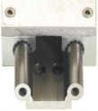
24 iglidur iglidur Plain Bearings High Performance iglidur Plain Bearings High Performance iglidur iglidur Plain Bearings 48 Table 48.1: Electrical properties of conductive iglidur plain bearings Material iglidur F 1.5 x 10 1 iglidur H 8.8 x 10 1 iglidur H x 10 3 iglidur X 6.9 x 10 2 Ø Surface resistance [Ω] Positions of the measurement planes Measurement of the inner diameter of a pressfit plain bearing Electrical properties In the product line of the maintenance free, self lubricating iglidur plain bearings, there are both insulating as well as electrically conductive materials. The most important electrical properties are given in detail in the individual material descriptions. Table 48.1 compares the most important electrical properties of iglidur plain bearings. The iglidur plain bearings not mentioned here are electrically insulating. Please observe that for some materials the properties can be changed by the material s absorption of moisture. In experiments, it should be tested whether the desired properties are also stable when the conditions are changing. Tolerances and measurement system The installation dimensions and tolerances of the iglidur plain bearings are a function of the material and wall thicknesses. For each material, the moisture absorption and the thermal expansion are imperative. Plain bearings with low moisture absorption can be designed when there is a minimal amount of tolerance. For wall thickness, the rule is: The thicker the bearings are, the larger the tolerances must be. Thus, different tolerance classes exist for iglidur plain bearings: Within these tolerances, iglidur plain bearings can operate in the permissible temperature range and in humidity conditions up to 70% according to the installation recommendations. Should higher air moisture levels be present, or the bearing is operated underwater, our application advice is available to help you use your bearings correctly. Testing methods iglidur plain bearings are pressfit bearings for bores machined to our recommendations. This pressfitting of the bearing fixes the bearing in the housing, and the inner diameter of the plain bearing is also formed upon pressfit. The bearing test is performed when the bearing is installed in a bore with the minimum specified dimension; both using an indicating caliper and a Go-No-Go gauge. the "Go-Side" of the Go-No-Go gauge, pressed into the bore, must pass easily through the bearing With the 3 point probe, the inner diameter of the bearing after pressfit must lie within the prescribed tolerance on the measurement plane. Troubleshooting In spite of careful manufacturing and assembly of the bearings, differences and questions regarding the recommended installation dimensions and tolerances can result. For this reason, we have compiled a list of the most frequent reasons for differences. In many cases, with this troubleshooter, the reasons for the differences can be found quickly. The bore is not chamfered properly the bearing material is removed upon pressfitting. A centering pin was used which expanded the inside diameter of the bearing during pressfit The bore does not meet the recommended housing bore specifications The housing is made out of a soft material that was expanded by the bearing installation The shaft is not within recommended tolerances. The measurement is not performed within the same parameters shown.. Machining iglidur plain bearings are delivered ready to install. The extensive product line makes it possible to use a standard dimension in most cases. If for some reason, a subsequent machining of the plain bearing is necessary, table shows the machining standard values. The subsequent machining of the running surfaces is to be avoided if possible. Higher wear rate is most often the result. An exception is the iglidur M250 which is very suitable for secondary machining. In other iglidur plain bearings, disadvantages of a sliding surface machining can be counteracted by lubrication during installation. Installation iglidur plain bearings are produced oversized as standard. The inner diameter adjusts only after pressfit in the proper housing bore with a recommended tolerance. The before pressfit oversized dimension can be up to 2% of the inner diameter. In this manner, the secure pressfitting of the bearing is achieved. Axial or radial shifts in the housing are also prevented. The bore in the housing should be finished in the recommended tolerance for all bearings and be as smooth, flat, and chamfered when possible. The installation is done using an flat press. The use of centering or calibrating pins can cause damage to the bearing and create a larger amount of clearance. Adhesion Adhering of the bearing is normally not necessary. If the pressfit of the bearing could be lost because of high temperatures, the use of a plain bearing having a higher temperature resistance is recommended. If however, the securing of the bearing by adhesives is planned, individual tests are necessary in each case. The transfer of successful results to other application cases is not possible. Table 49.1: Guidelines for machining Process Turning Boring Milling Tool material SS SS SS Feed [mm] > 0.5 Tool relief angle Tool rake angle Cutting speed [m/min] > 1000 Section view: pressfit of the bearing The installation Lifetime calculation, CAD files and much more support Lifetime calculation, CAD files and much more support iglidur Plain Bearings mm 49

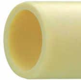
25 G iglidur G the Allround Performer iglidur G Information and Technical Data G Product Range iglidur G bearings cover an extremely wide range of differing requirements they are truly allround. Application is recommended for medium to high loads, medium sliding velocities Permissible p x v - values for running dry against a steel shaft, at 20 C Coefficient of friction of iglidur G as a function of the running speed, p = 0.75 MPa iglidur G 3 Styles > 904 Dimensions Ø mm +130º 40º and medium temperatures. Load [MPa] ,0 Coefficient of friction µ 0,5 0,4 0,3 0,2 iglidur G Max. running speed 0,1 0,01 0,1 1,0 10 0,1 0,05 0,10 0,15 0,20 0,25 0,30 0,35 [m/s] Continuous Short term Surface speed [m/s] Surface speed [m/s] Rotating 1 2 Oscillating Linear 4 5 Price index When to use iglidur G Maintenance free, dry running Multi purpose use Dirt resistant Vibration dampening High wear resistance Resistance to dust and dirt Over 900 sizes available from stock Cost effective Economical all round performance bearing For above average loads For low to When not to use iglidur G When mechanical reaming of the wall surface is necessary iglidur M250 When the highest wear resistance is necessary iglidur W300 Recommended max. permissible static surface pressure as a function of temperature Load [MPa] Coefficient of friction of iglidur G as a function of the load Coefficient of friction µ 0,35 0,30 0,25 0,20 0,15 0,10 0,05 0, average running speeds When the bearing needs Temperature in C Load [MPa] Conveyor chains: Through edge to run on different shaft materials For oscillating loading, short term surface pressures of over 50 MPa can occur and rotational movements Material table iglidur G deformation under load and temperature Coefficient of friction as function of the shaft surface (shaft cold rolled steel) The pneumatic rotational drive unit in steam lines at steam temperatures up to 135 C General properties Unit iglidur G Testing method Density g/cm Colour dark grey Max. moisture absorption at 23 C / 50% r.f. % weight 0.7 DIN Max. moisture absorption % weight 4.0 Coefficient of sliding friction, dynamic against steel µ (Ra = 1 µm, 50 HRC) p x v Value, max. (dry) MPa x m/s 0.42 Mechanical properties Modulus of elasticity MPa 7,800 DIN Tensile strength at 20 C MPa 210 DIN Deformation in % Coefficient of friction µ 0,5 0,4 0,3 0,2 0,1 0,0 0,0 0,5 1,0 1,5 2,0 mm Compressive strength MPa 78 Load [MPa] 23 C 60 C Shaft roughness Ra [µm] Max. static surface pressure (20 C) MPa 80 Shore D hardness 81 DIN Tests under high radial forces, distances of 3,ooo km are covered with negligible wear values Physical and thermal properties Max. long term application temperature C 130 Max. short term application temperature C 220 Min. application temperature C -40 Thermal conductivity [W/m x K] 0.24 ASTM C 177 Coefficient of thermal expansion (at 23 C) [K -1 x 10⁻⁵ ] 9 DIN Electrical properties Specific volume resistance Ω cm > DIN IEC 93 Surface resistance Ω > DIN Lifetime calculation, CAD files and much more support Lifetime calculation, CAD files and much more support 51
26 G iglidur G Information and Technical Data iglidur G Sleeve Bearing Type S G iglidur G Wear rotating with different shaft materials, load p = 0.75 MPa, v = 0.5 m/s Wear [µm/km] ,2 1,6 Shaft materials 2,5 2,6 Wear with different shaft materials in rotational operation, as a function of the load Wear [µm/km] 3,2 3,5 4,4 6, Wear for pivoting and rotating applications with shaft material cold rolled steel 1018, as a function of the load Wear [µm/km] Free cutting HRCS 303 CRS Hard chromed Drill rod HSS Temperature in C CR Steel Hard chromed 303 HR Carbon steel H. A. Aluminum Load [MPa] CR Steel (rotating) CR Steel (pivoting) Effect of moisture absorption on iglidur G plain bearings Reduction of the inner diameter [%] 0,6 0,5 0,4 0,3 0,2 0,1 0,0 iglidur G 0,0 0,5 1,0 1,5 2,0 2,5 3,0 3,5 4,0 Moisture absorption [weight %] Electrical properties of iglidur G Specific volume resistance Surface resistance > Ω cm > Ω Important tolerances for iglidur G plain bearings after pressfit Diameter Shaft h9 iglidur G d1 [mm] [mm] E10 [mm] up to > 3 to > 6 to > 10 to > 18 to > 30 to > 50 to > 80 to > Chemical resistance of iglidur G Medium Alcohols Chlorinated hydrocarbons Esters Greases, Oils Ketone Fuels Weak acids Strong acids Weak alkalines Strong alkalines Resistance Resistant Resistant Not resistant Resistant Conditionally resistant Resistant Conditionally resistant Not resistant Conditionally resistant Conditionally resistant f = 0,3 d1 = 1 6 Structure Part No. f = 0,5 d1 = 6 12 G S M f = 0,8 f = 1,2 d1 = d1 > 30 b1 d2 Chamfer in relation to the d1 Dimensions according to ISO and special dimensions *after Pressfit in Ø H7 d1 Dimen. Type Material Part No. d1 d2 b1 h13 d1-tol.* Part No. d1 d2 b1 h13 d1-tol.* GSM GSM GSM GSM GSM GSM GSM GSM GSM GSM GSM GSM GSM GSM GSM GSM GSM GSM GSM GSM GSM GSM GSM GSM GSM GSM GSM GSM GSM GSM GSM GSM GSM GSM GSM GSM GSM GSM GSM GSM GSM GSM GSM GSM GSM GSM GSM GSM GSM GSM GSM GSM GSM GSM GSM GSM GSM GSM GSM GSM GSM GSM GSM GSM GSM GSM GSM GSM GSM GSM GSM GSM GSM GSM GSM GSM GSM GSM GSM GSM GSM GSM GSM GSM GSM GSM GSM GSM GSM GSM GSM GSM GSM GSM GSM GSM iglidur G mm 52 Lifetime calculation, CAD files and much more support Lifetime calculation, CAD files and much more support 53
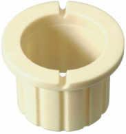
27 G iglidur G Sleeve Bearing Type S iglidur G Flange Bearing Type F G iglidur G 54 Part No. d1 d2 b1 h13 d1-tol.* Part No. d1 d2 b1 h13 d1-tol.* f = 0,3 d1 = 1 6 Structure Part No. GSM GSM f = 0,5 d1 = 6 12 G F M GSM GSM f = 0,8 d1 = b1 GSM GSM f = 1,2 d1 > 30 d2 GSM GSM Chamfer in relation to the d1 d1 GSM GSM Dimensions according to ISO Dimen. GSM GSM and special dimensions Type GSM GSM *after Pressfit in Ø H7 Material GSM GSM GSM GSM Part No. d1 d2 d3 b1 b2 d1-tol.* Part No. d1 d2 d3 b1 b2 d1-tol.* GSM GSM d13 h d13 h GSM GSM GFM GFM GSM GSM GFM GFM GSM GSM GFM GFM GSM GSM GFM GFM GSM GSM GFM GFM GSM GSM GFM GFM GSM GSM GFM GFM GSM GSM GFM GFM GSM GSM GFM GFM GSM GSM GFM GFM GSM GSM GFM GFM GSM GSM GFM GFM GSM GSM GFM GFM GSM GSM GFM GFM GSM GSM GFM GFM GSM GSM GFM GFM GSM GSM GFM GFM GSM GSM GFM GFM GSM GSM GFM GFM GSM GSM GFM GFM GSM GSM GFM GFM GSM GSM GFM GFM GSM GSM GFM GFM GSM GSM GSM GSM GFM GFM GSM GSM GFM GFM GSM GSM GFM GFM GSM GSM GFM GFM GSM GSM GFM GFM GSM GSM GFM GFM GSM GSM GFM GFM GSM GSM GFM GFM GSM GSM GFM GFM GSM GSM GFM GFM GSM GSM GFM GFM GSM GSM GFM GFM GSM GSM GFM GFM GSM GSM GFM GFM GSM GSM GFM GFM GSM GSM GFM GFM GSM GSM GFM GFM GSM GSM GFM GFM GSM GSM GFM GFM GSM GSM GFM GFM GSM GSM GFM GFM GSM GFM GFM GSM GFM GFM Lifetime calculation, CAD files and much more support Lifetime calculation, CAD files and much more support iglidur G mm 55
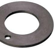
28 G iglidur G Flange Bearing Type F iglidur G Thrust Washer Type T G iglidur G Part No. d1 d2 d3 b1 b2 d1-tol.* d13 h GFM GFM GFM GFM GFM GFM GFM GFM GFM GFM GFM GFM GFM GFM GFM GFM GFM GFM GFM GFM GFM GFM GFM GFM GFM GFM GFM GFM GFM GFM GFM GFM GFM GFM GFM GFM GFM GFM GFM GFM GFM GFM GFM GFM GFM GFM GFM GFM GFM GFM GFM GFM GFM GFM GFM Part No. d1 d2 d3 b1 b2 d1-tol.* d13 h GFM GFM GFM GFM GFM GFM GFM GFM GFM GFM GFM GFM GFM GFM GFM Dimensions according to ISO and special dimensions Structure Part No. G T M s d2 d1 Dimen. Type * Design without fixation bore Material Part No. d1 d2 s d4 d5 h d GTM * * GTM * * GTM GTM * * GTM * * GTM GTM * * GTM GTM GTM * * GTM * * GTM GTM * * GTM GTM * * GTM GTM * * GTM GTM GTM GTM GTM GTM GTM * * GTM GTM GTM GTM GTM GTM GTM GTM * * iglidur G mm 56 Lifetime calculation, CAD files and much more support Lifetime calculation, CAD files and much more support 57

29 W300 iglidur W300 The Marathon Runner iglidur W300 Information and Technical Data W300 iglidur W300 Product Range 3 Styles > 675 Dimensions Ø 2 90 mm +90º High wear resistance, even in harsh environments or in connection with rough shafts, characterizes the iglidur W300 material. Of all iglidur materials, this material is the most resistant to these types of external effects. Permissible p x v - values for iglidur W300 running dry against a steel shaft, at 20 C Load [MPa] 100,00 10,00 1,00 Coefficient of friction as a function of the surface speed, p = 0.75 MPa, (shaft cold rolled steel) Coefficient of friction µ 0,5 0,4 0,3 iglidur W300 40º Max. running speed [m/s] Continuous Short term Rotating Oscillating 2 3 Linear 5 6 Price index With iglidur W300 the life of the bearing on this machine could be increased five times For small driving forces, very low coefficients of friction occur Highest wear resistance even in those places where abrasive media contact the bearing When to use iglidur W300 For especially high service life Low coefficient of friction Extremely high wear resistance Also suitable for soft shafts Resistant to chemicals When low coefficients of dynamic friction and high wear resistance are needed For use on 303 stainless steel shafts For harsh environments iglidur G and very rough shafts Dirt resistant Material table When not to use iglidur W300 For high loads starting at 50 MPa iglidur Q When temperatures are constantly above 130 C iglidur H, X When an especially economical bearing is desired General properties Unit iglidur W300 Testing method Density g/cm Colour yellow Max. moisture absorption at 23 C / 50% r.f. % weight 1.3 DIN Max. moisture absorption % weight 6.5 Coefficient of sliding friction, dynamic against steel µ (Ra = 1 µm, 50 HRC) p x v Value, max. (dry) MPa x m/s 0.23 Mechanical properties Modulus of elasticity MPa 3,500 DIN Tensile strength at 20 C MPa 125 DIN Compressive strength MPa 61 Max. static surface pressure (20 C) MPa 60 Shore D hardness 77 DIN Physical and thermal properties Max. long term application temperature C 90 Max. short term application temperature C 180 Min. application temperature C -40 Thermal conductivity [W/m x K] 0.24 ASTM C 177 Coefficient of thermal expansion (at 23 C) [K -1 x 10⁻⁵ ] 9 DIN Electrical properties Specific volume resistance Ω cm > DIN IEC 93 Surface resistance Ω > DIN ,10 0,001 0,01 0,1 1,0 10 Recommended max. permissible static surface pressure as a function of temperature Load [MPa] iglidur W300 deformation under load and temperature Deformation in % Surface speed [m/s] Temperature in C Load [MPa] 23 C 60 C 0,2 0,05 0,10 0,15 0,20 0,25 0,30 0,35 Coefficient of friction of iglidur W300 as a function of the load, v = 0.01 m/s Coefficient of friction µ 0,30 0,25 0,20 0,15 0,10 0,05 0,00 0 0,35 0,30 0,25 0,20 Surface speed [m/s] Load [MPa] Coefficient of friction as function of the shaft surface (shaft cold rolled steel) Coefficient of friction µ 0,15 0,1 0,4 0,7 1,0 1,3 1,6 Shaft roughness Ra [µm] mm 58 Lifetime calculation, CAD files and much more support Lifetime calculation, CAD files and much more support 59
30 W300 iglidur W300 Information and Technical Data iglidur W300 Sleeve Bearing Type S W300 iglidur W300 Wear of iglidur W300, with different shaft materials, p = 0.75 MPa, v = 0,5 m/s Wear [µm/km] 1,6 1,6 1,4 1,4 1,2 1,2 11 0,8 0,8 0,6 0,6 0,4 0,4 0,2 0,2 2,5 2,0 1,5 1,0 0,5 0,0 0,1 0,2 0 0 Shaft materials 0,3 0,3 0,8 1,3 1,5 1,5 Wear with different shaft materials in rotational operation, as a function of the load Wear [µm/km] ,0 0,5 1,0 1,5 2,0 Temperature in C CR Steel (rotating) Steel (rotating) Hard chromed HR Carbon steel Wear for oscillating and rotating applications with shaft material cold rolled steel, as a function of the load Wear [µm/km] HSS Hard chromed Drill rod 303 CRS Aluminum Free cutting HRCS 0 0,25 0,75 2,00 5,00 10,00 45,00 76,00 Load [MPa] CR Steel (rotating) CR Steel (oscillating) Effect of moisture absorption on iglidur W300 plain bearings Reduction of the inner diameter [%] 0,7 0,6 0,5 0,4 0,3 0,2 0,1 0,0 0,0 0,81 1,63 2,44 3,25 4,06 4,88 5,69 6,5 Moisture absorption [weight %] Electrical properties of iglidur W300 iglidur W300 Specific volume resistance Surface resistance > Ωcm > Ω Essential tolerances for iglidur W300 plain bearings after pressfit Diameter Shaft h9 iglidur W300 d1 [mm] [mm] E10 [mm] up to > 3 to > 6 to > 10 to > 18 to > 30 to > 50 to > 80 to > Chemical resistance of iglidur W300 Medium Alcohols Chlorinated hydrocarbons Esters Greases, Oils Ketone Fuels Weak acids Strong acids Weak alkalines Strong alkalines Resistance Resistant Resistant Not resistant Resistant Conditionally resistant Resistant Conditionally resistant Not resistant Resistant Conditionally resistant f = 0,3 d1 = 1 6 Structure Part No. f = 0,5 d1 = 6 12 W S M f = 0,8 f = 1,2 d1 = d1 > 30 b1 d2 Chamfer in relation to the d1. Dimensions according to ISO and special dimensions *after Pressfit in Ø H7 d1 Dimen. Type Material Part No. d1 d2 b1 h13 d1-tol.* Part No. d1 d2 b1 h13 d1-tol.* WSM WSM WSM WSM WSM WSM WSM WSM WSM WSM WSM WSM WSM WSM WSM WSM WSM WSM WSM WSM WSM WSM WSM WSM WSM WSM WSM WSM WSM WSM WSM WSM WSM WSM WSM WSM WSM WSM WSM WSM WSM WSM WSM WSM WSM WSM WSM WSM WSM WSM WSM WSM WSM WSM WSM WSM WSM WSM WSM WSM WSM WSM WSM WSM WSM WSM WSM WSM WSM WSM WSM WSM WSM WSM WSM WSM WSM WSM WSM WSM WSM WSM WSM WSM WSM WSM WSM WSM WSM WSM WSM WSM WSM WSM iglidur W300 mm 60 Lifetime calculation, CAD files and much more support Lifetime calculation, CAD files and much more support 61
31 W300 iglidur W300 Sleeve Bearing Type S iglidur W300 Flange Bearing Type F W300 iglidur W Part No. d1 d2 b1 h13 d1- f = 0,3 d1 = 1 6 Structure Part No. WSM f = 0,5 d1 = 6 12 W F M WSM f = 0,8 d1 = b1 WSM f = 1,2 d1 > 30 d2 WSM Chamfer in relation to the d1. d1 WSM Dimensions according to ISO Dimen. WSM and special dimensions Type WSM *after Pressfit in Ø H7 Material WSM WSM Part No. d1 d2 d3 b1 b2 d1-tol.* Part No. d1 d2 d3 b1 b2 d1-tol.* WSM d13 h d13 h WSM WFM WFM WSM WFM WFM WSM WFM WFM WSM WFM WFM WSM WFM WFM WSM WFM WFM WSM WFM WFM WSM WFM WFM WSM WFM WFM WSM WFM WFM WSM WFM WFM WSM WFM WFM WSM WFM WFM WSM WFM WFM WSM WFM WFM WSM WFM WFM WSM WFM WFM WSM WFM WFM WSM WFM WFM WSM WFM WFM WSM WFM WFM WSM WFM WFM WSM WFM WFM WSM WFM WFM WSM WFM WFM WSM WFM WFM WSM WFM WFM WSM WFM WFM WSM WFM WFM WSM WFM WFM WSM WFM WFM WFM WFM WFM WFM WFM WFM WFM WFM WFM WFM WFM WFM WFM WFM WFM WFM WFM WFM WFM WFM WFM WFM WFM WFM WFM WFM WFM WFM WFM WFM Lifetime calculation, CAD files and much more support Lifetime calculation, CAD files and much more support iglidur W300 mm 63
32 W300 iglidur W300 Flange Bearing Type F iglidur W300 Thrust Washer Type T W300 iglidur W300 Part No. d1 d2 d3 b1 b2 d1-tol.* d13 h WFM WFM WFM WFM WFM WFM WFM WFM WFM WFM WFM WFM WFM WFM WFM WFM WFM WFM WFM WFM WFM WFM WFM WFM WFM WFM WFM WFM WFM WFM WFM WFM WFM WFM WFM WFM WFM WFM WFM Dimensions according to ISO and special dimensions Structure Part No. W T M s d2 d1 * Design without fixation bore Dimen. Type Material Part No. d1 d2 s d4 d5 h d6 +0,25-0,25-0,05-0,12 +0,375 +0,2 +0,12 +0,12 +0,125-0,2 WTM * * WTM WTM WTM WTM WTM WTM WTM WTM WTM WTM WTM WTM WTM WTM WTM WTM WTM WTM WTM WTM * * WTM * * WTM * * iglidur W300 mm 64 Lifetime calculation, CAD files and much more support Lifetime calculation, CAD files and much more support 65

33 X iglidur X the High Tech Problem Solver iglidur X Information and Technical Data X iglidur X Product Range 3 Styles > 566 Dimensions Ø 2 75 mm +250º 100º iglidur X is defined by its combination of high temperature resistance with compressive strength, along with high resistance to chemicals. iglidur X is designed for higher speeds than other iglidur bearings. Permissible p x v - values for iglidur X running dry against a steel shaft, at 20 C Load [MPa] Coefficient of friction as a function of the running speed, p = 0.75 MPa, shaft cold rolled steel Coefficient of friction µ 0,4 0,3 0,2 iglidur X Max. running speed [m/s] Continuous Short term Rotating Oscillating 3 4 Linear 5 6 Price index Intake control device with iglidur X Flaps, valves with iglidur X Catering equipment with iglidur X When to use iglidur X Temperature resistant from -100 C to +250 C in continuous operation (short term to C) Universal resistance to chemicals High compressive strength Very low moisture absorption High wear resistance through the For edge pressure entire temperature range For pressure loads up iglidur Z to 150 MPa For linear movements with stainless steel For linear movements, especially at high temperatures Material table When not to use iglidur X For very low wear at high loads iglidur Q, Z For underwater applications iglidur H, H370 General properties Unit iglidur X Testing method Density g/cm Colour Black Max. moisture absorption at 23 C / 50% r.f. % weight 0.1 DIN Max. moisture absorption % weight 0.5 Coefficient of sliding friction, dynamic against steel µ (Ra = 1 µm, 50 HRC) p x v Value, max. (dry) MPa x m/s 1.32 Mechanical properties Modulus of elasticity MPa 8,100 DIN Tensile strength at 20 C MPa 170 DIN Compressive strength MPa 100 Max. static surface pressure (20 C) MPa 150 Shore D hardness 85 DIN Physical and thermal properties Max. long term application temperature C 250 Max. short term application temperature C 315 Min. application temperature C -100 Thermal conductivity [W/m x K] 0.6 ASTM C 177 Coefficient of thermal expansion (at 23 C) [K -1 x 10⁻⁵ ] 5 DIN Electrical properties Specific volume resistance Ωcm > 10 5 DIN IEC 93 Surface resistance Ω > 10 3 DIN ,1 0,001 0,01 0, Recommended max. permissible static surface pressure of iglidur X as a function of temperature Load [MPa] Surface speed [m/s] Temperature in C iglidur X deformation under load and temperature Deformation in % Load [MPa] 23 C 60 C 0,1 0,05 0,10 0,15 0,20 0,25 0,30 0,35 Surface speed [m/s] Coefficient of friction for iglidur X as a function of the load, v = 0.01 m/s Coefficient of friction µ 0,35 0,30 0,25 0,20 0,15 0,10 0,05 0, Load [MPa] Coefficients of friction as a function of the shaft surface (shaft cold rolled steel) Coefficient of friction µ 0,90 0,80 0,70 0,60 0,50 0,40 0,30 0,20 0,1 0,4 0,7 1,0 1,3 1,6 Shaft roughness Ra [µm] mm 66 Lifetime calculation, CAD files and much more support Lifetime calculation, CAD files and much more support 67
34 X iglidur X Information and Technical Data iglidur X Sleeve Bearing Type S X iglidur X Wear of iglidur X, Rotation with p = 0.75 MPa, v = 0.5 m/s, shaft made of cold rolled steel Wear [µm/km] Wear of iglidur X with different shaft materials, p = 0.75 MPa, v = 0.5 m/s Wear [µm/km] Wear of iglidur X with different shaft materials Wear [µm/km] 12,0 10, ,0 10,0 8,0 6,0 4,0 2,0 8,0 6,0 4,0 2, Load [MPa] CF53 HRCS Hard chromed 303 S. Steel Electrical properties of iglidur X iglidur X 3,5 SS Specific volume resistance Surface resistance 5,1 Drill rod 7,1 Temperature in C Shaft materials 7,0 7,1 HRCS CRS > 10 5 Ωcm > 10 3 Ω 7,8 Hard chromed 8,6 HSS 2,2 23 C 150 C 9,3 H. A. Aluminum 10,0 304 S. Steel Wear for oscillating and rotating applications with different shaft materials Wear [µm/km] ,3 21,7 Material Oscillating, p = 2 MPa Effect of moisture absorption on iglidur X plain bearings Reduction of the inner diameter [%] 12,8 20,5 Essential tolerances for iglidur X plain bearings Chemical resistance of iglidur X Rotating, p = 2 MPa Diameter Shaft h9 iglidur X d1 [mm] [mm] F10 [mm] up to > 3 to > 6 to > 10 to > 18 to > 30 to > 50 to Medium Alcohols Chlorinated hydrocarbons Esters Greases, Oils Ketone Fuels 0,10 0,08 0,06 0,04 0,02 0,00 0,0 0,1 0,2 0,3 0,4 0,5 Moisture absorption [weight %] Weak acids Strong acids Weak alkalines Strong alkalines Cold rolled steel Resistance Resistant Resistant Resistant Resistant Resistant Resistant Resistant Conditionally resistant Resistant Resistant 303 Stainless steel f = 0,3 d1 = 1 6 Structure Part No. f = 0,5 d1 = 6 12 X S M f = 0,8 f = 1,2 d1 = d1 > 30 b1 d2 Chamfer in relation to the d1. Dimensions according to ISO and special dimensions *after Pressfit in Ø H7 d1 Dimen. Type Material Part No. d1 d2 b1 h13 d1-tol.* Part No. d1 d2 b1 h13 d1-tol.* XSM XSM XSM XSM XSM XSM XSM XSM XSM XSM XSM XSM XSM XSM XSM XSM XSM XSM XSM XSM XSM XSM XSM XSM XSM XSM XSM XSM XSM XSM XSM XSM XSM XSM XSM XSM XSM XSM XSM XSM XSM XSM XSM XSM XSM XSM XSM XSM XSM XSM XSM XSM XSM XSM XSM XSM XSM XSM XSM XSM XSM XSM XSM XSM XSM XSM XSM XSM XSM iglidur X mm 68 Lifetime calculation, CAD files and much more support Lifetime calculation, CAD files and much more support 69
35 X iglidur X Flange Bearing Type F iglidur X Thrust Washer Type T X iglidur X f = 0,3 d1 = 1 6 f = 0,5 d1 = 6 2 f = 0,8 d1 = f = 1,2 d1 > 30 Chamfer in relation to the d1. Dimensions according to ISO and special dimensions *after Pressfit in Ø H7 Structure Part No. X F M b1 d2 d1 Dimen. Type Material Dimensions according to ISO and special dimensions * Design without fixation bore Structure Part No. X T M s d2 d1 Dimen. Type Material iglidur X Part No. d1 d2 d3 b1 b2 d1-tol.* d13 h XFM XFM XFM XFM XFM XFM XFM XFM XFM XFM XFM XFM XFM XFM XFM XFM XFM XFM XFM XFM XFM XFM XFM XFM XFM XFM XFM XFM XFM XFM XFM XFM XFM XFM XFM XFM XFM XFM XFM XFM XFM XFM Part No. d1 d2 s d4 d5 h d6 +0,25-0,25-0,05-0,12 +0,375 +0,2 +0,12 +0,12 +0,125-0,2 XTM XTM XTM * * XTM XTM XTM XTM XTM XTM XTM XTM XTM XTM XTM XTM XTM XTM XTM mm 70 Lifetime calculation, CAD files and much more support Lifetime calculation, CAD files and much more support 71

36 0,001 0,01 0,1 1 2 M250 iglidur M250 Thick and Robust iglidur M250 Information and Technical Data M250 iglidur M250 Product Range 2 Styles > 603 Dimensions Ø 1 32 mm +80º The self lubricating plain bearings made of iglidur M250 are defined by their impact strength, vibration dampening, and wear resistant properties. They excel in applications in which vibration dampening is necessary, for example, in fitness and packaging machines. Permissible p x v - values for iglidur M250 running dry against a steel shaft, at 20 C Load [MPa] 100, , ,00 10 Coefficient of friction of iglidur M250 as a function of the surface speed, p = 0.75 MPa Coefficient of friction µ 0,7 0,6 0,5 0,4 iglidur M250 40º 0,10 1 0,3 Max. running speed [m/s] Continuous Short term Rotating Oscillating Linear Price index Precision mechanical gears need plain bearings with especially universal properties In this analytical pump, sewage water is tested with chemicals and floating particles iglidur M250 as a wheel bearing in lawn mowers corrosion resistant and vibration damped When to use iglidur M250 Excellent vibration dampening Resistant to edge loading High impact resistance Thick walled according to DIN 1850 Dirt can become embedded for shaft protection When the bearings are exposed to high amounts of dirt when high vibration damping is necessary For low to average speeds When mechanical reaming of the wall surface is necessary Material table When not to use iglidur M250 When very high precision is necessary iglidur P For underwater use iglidur H For very smooth shafts iglidur J General properties Unit iglidur M250 Testing method Density g/cm Colour charcoal Max. moisture absorption at 23 C / 50% r.f. % weight 1.4 DIN Max. moisture absorption % weight 7.6 Coefficient of sliding friction, dynamic against steel µ (Ra = 1 µm, 50 HRC) p x v Value, max. (dry) MPa x m/s 0.12 Mechanical properties Modulus of elasticity MPa 2,700 DIN Tensile strength at 20 C MPa 112 DIN Compressive strength MPa 52 Max. static surface pressure (20 C) MPa 20 Shore D hardness 79 DIN Physical and thermal properties Max. long term application temperature C 80 Max. short term application temperature C 170 Min. application temperature C -40 Thermal conductivity [W/m x K] 0.24 ASTM C 177 Coefficient of thermal expansion (at 23 C) [K -1 x 10⁻⁵ ] 10 DIN Electrical properties Specific volume resistance Ωcm > DIN IEC 93 Surface resistance Ω > DIN ,1 0,01 0,001 0,01 0,1 1 2 Recommended max. permissible static surface pressure as a function of temperature Load [MPa] , iglidur M250 deformation under load and temperature Deformation in % Surface speed [m/s] Temperature in C 0,2 0, , , , , , , Surface speed [m/s] Coefficient of friction of iglidur M250 as a function of the load, v = , ,1 0,4 0,7 1,0 1,3 1,6 Load [MPa] 23 C 60 C Coefficient of friction µ 0,6 0,5 0,4 0,3 0,2 0,1 Coefficient of friction as function of the shaft surface (shaft cold rolled steel) Coefficient of friction µ 0,60 0,55 0,50 0,45 0,40 0,35 Load [MPa] Shaft roughness Ra [µm] mm 72 Lifetime calculation, CAD files and much more support Lifetime calculation, CAD files and much more support 73
37 M250 iglidur M250 Information and Technical Data iglidur M250 Sleeve Bearing Type S M250 iglidur M250 Wear of iglidur M250, rotating with different shaft materials, load p = 0.75 MPa, v = 0.5 m/s Wear [µm/km] 4,5 4,0 3,5 3,0 2,5 2,0 1,5 1,0 0, ,5 18,4 5,6 1,0 1,1 0,0 Shaft materials 14,9 1,3 1,4 1,5 Wear of iglidur M250 with different shaft materials in rotational operation Wear [µm/km] Wear [µm/km] 10,0 8,0 6,0 4,0 2,0 Hard chromed HRCS 303 SS 0,0 0,0 1,0 2,0 3,0 4,0 5,0 Load [MPa] Cf SS Hard chromed HRCS Wear for oscillating and rotating applications with different shaft materials at p = 2 MPa Free cutting 5,0 37,9 HSS H. A. Alu 7,2 2,0 Drill rod 27,8 3,9 Cf53 2,25 Cold rolled 303 Stainless HR Hard steel steel Carbon steel chromed Material Oscillating, p = 2 MPa Rotating, p = 2 MPa Effect of moisture absorption on iglidur M250 plain bearings Reduction of the inner diameter [%] 1,4 1,2 1,0 0,8 0,6 0,4 0,2 0,0 0,0 1,0 2,0 3,0 4,0 5,0 6,0 7,0 8,0 Moisture absorption [weight %] Electrical properties of iglidur M250 iglidur M250 Specific volume resistance Surface resistance > Ωcm > Ω Essential tolerances for iglidur M250 plain bearings after pressfit Diameter Shaft h9 iglidur M250 d1 [mm] [mm] D11 [mm] up to > 3 to > 6 to > 10 to > 18 to > 30 to Chemical resistance of iglidur M250 Medium Alcohols Chlorinated hydrocarbons Esters Greases, Oils Ketone Fuels Weak acids Strong acids Weak alkalines Strong alkalines Resistance Resistant Resistant Not resistant Resistant Conditionally resistant Resistant Resistant Conditionally resistant Resistant Conditionally resistant f = 0,3 d1 = 1 6 Structure Part No. f = 0,5 d1 = 6 12 M S M f = 0,8 f = 1,2 d1 = d1 > 30 b1 d2 Chamfer in relation to the d1. Dimensions according to DIN 1850 and special dimensions *after Pressfit in Ø H7 d1 Dimen. Type Material Part No. d1 d2 b1 h13 d1-tol.* Part No. d1 d2 b1 h13 d1-tol.* MSM MSM MSM MSM MSM MSM MSM MSM MSM MSM MSM MSM MSM MSM MSM MSM MSM MSM MSM MSM MSM MSM MSM MSM MSM MSM MSM MSM MSM MSM MSM MSM MSM MSM MSM MSM MSM MSM MSM MSM MSM MSM MSM MSM MSM MSM MSM MSM MSM MSM MSM MSM MSM MSM MSM MSM MSM MSM MSM MSM MSM MSM MSM MSM MSM MSM MSM MSM MSM MSM MSM MSM MSM MSM MSM MSM MSM MSM MSM MSM MSM MSM MSM MSM MSM MSM MSM MSM MSM MSM MSM MSM MSM MSM iglidur M250 mm 74 Lifetime calculation, CAD files and much more support Lifetime calculation, CAD files and much more support 75
38 M250 iglidur M250 Sleeve Bearing Type S iglidur M250 Flange Bearing Type F M250 iglidur M Part No. d1 d2 b1 h13 d1-tol.* f = 0,3 d1 = 1 6 Structure Part No. MSM f = 0,5 d1 = 6 12 M F M MSM f = 0,8 d1 = b1 MSM f = 1,2 d1 > 30 d2 MSM Chamfer in relation to the d1. d1 MSM Dimensions according to DIN Dimen. MSM and special dimensions Type MSM *after Pressfit in Ø H7 Material MSM MSM Part No. d1 1) d2 d3 b1 b2 d1-tol.* Part No. d1 d2 d3 b1 b2 d1-tol.* MSM d13 h d13 h MSM MFM MFM MSM MFM MFM MSM MFM MFM MSM MFM MFM MSM MFM MFM MSM MFM MFM MSM MFM MFM MSM MFM MFM MSM MFM MFM MSM MFM MFM MSM MFM MFM MSM MFM MFM MSM MFM MFM MSM MFM MFM MSM MFM MFM MSM MFM MFM MSM MFM MFM MSM MFM MFM MSM MFM MFM MSM MFM MFM MSM MFM MFM MSM MFM MFM MSM MFM MFM MSM MFM MFM MSM MFM MFM MSM MFM MFM MSM MFM MFM MSM MFM MFM MSM MFM MFM MSM MFM MFM MSM MFM MFM MSM MFM MFM MSM MFM MFM MFM MFM MFM MFM MFM MFM MFM MFM MFM MFM MFM MFM MFM MFM MFM MFM MFM MFM MFM MFM MFM MFM MFM MFM MFM MFM Lifetime calculation, CAD files and much more support Lifetime calculation, CAD files and much more support iglidur M250 mm 77
39 M250 iglidur M250 Flange Bearing Type F iglidur M250 Thrust Washer Type T M250 iglidur M250 Part No. d1 d2 d3 b1 b2 d1-tol.* d13 h MFM MFM MFM MFM MFM MFM MFM MFM MFM MFM MFM MFM MFM MFM MFM MFM MFM MFM MFM MFM MFM MFM MFM MFM MFM MFM MFM MFM MFM MFM MFM MFM MFM MFM MFM MFM MFM MFM MFM MFM MFM MFM MFM MFM MFM MFM MFM MFM MFM MFM MFM MFM MFM MFM MFM Part No. d1 d2 d3 b1 b2 d1-tol.* d13 h MFM MFM MFM MFM MFM MFM MFM MFM MFM MFM MFM MFM MFM MFM MFM MFM MFM MFM MFM Dimensions according to DIN Structure Part No and special dimensions M T I - 04 Part No. d1 (nominal) d1 d2 s max. min. max. min. MTI-04 1/ MTI-05 5/ MTI-06 3/ MTI-08 1/ MTI-10 5/ MTI-12 3/ MTI MTI / MTI / d1 Inch Type Material iglidur M250 mm 78 Lifetime calculation, CAD files and much more support Lifetime calculation, CAD files and much more support 79

40 J iglidur J The Fast and Slow-Motion Specialist iglidur J Information and Technical Data J iglidur J Product Range 3 Styles > 517 Dimensions Ø 1 75 mm +90º The iglidur J plain bearings are designed for the lowest coefficients of friction while running dry and their low stick slip tendency. With a maximum permissible surface pressure of 35 MPa iglidur J plain bearings are not suited for extreme loads. Permissible p x v - values for iglidur J running dry against a steel shaft, at 20 C Load [MPa] Coefficient of friction of iglidur J as a function of the surface speed - p = 0.75 MPa Coefficient of friction µ 0,4 0,3 0,2 iglidur J 50º 0,1 Max. running speed [m/s] Continuous Short term Rotating Oscillating Linear 8 10 Price index When to use iglidur J Low wear against different shaft up to 5 MPa Low coeffficients of friction in dry run Vibration dampening Good chemical resistance Best perfomance behaviour with soft shaft materials Low moisture absorption When a cost effective bearing for low pressure loads is needed For high speeds For high wear resistance When not to use iglidur J When high pressure loads occur iglidur G or W300 When temperatures occur that are greater than 120 C for a short term iglidur G For oscillation movement on 303 stainless shaft iglidur H370 Recommended max. static surface pressure of iglidur J as a function of temperature Load [MPa] 0,01 0,001 0,01 0, Surface speed [m/s] 0,1 0,05 0,05 0,10 0,15 0,20 0,25 0,30 0,35 Coefficient of friction of iglidur J as a function of the load, v = 0,01m/s Coefficient of friction µ 0 0, Temperature in C 0,30 0,25 0,20 0,15 0,10 0,05 Surface speed [m/s] Load [MPa] Material table General properties Unit iglidur J Testing method Density g/cm Colour yellow Max. moisture absorption at 23 C / 50% r.f. % weight 0.3 DIN Max. moisture absorption % weight 1.3 Coefficient of sliding friction, dynamic against steel µ (Ra = 1 µm, 50 HRC) p x v Value, max. (dry) MPa x m/s 0.34 Mechanical properties Modulus of elasticity MPa 2,400 DIN Tensile strength at 20 C MPa 73 DIN Compressive strength MPa 60 Max. static surface pressure (20 C) MPa 35 Shore D hardness 74 DIN Physical and thermal properties Max. long term application temperature C 90 Max. short term application temperature C 120 Min. application temperature C -50 Thermal conductivity [W/m x K] 0.25 ASTM C 177 Coefficient of thermal expansion (at 23 C) [K -1 x 10⁻⁵ ] 10 DIN Electrical properties Specific volume resistance Ωcm > DIN IEC 93 Surface resistance Ω > DIN iglidur J deformation under load and temperature Deformation in % 10 7,5 5 2, , ,5 50 Load [MPa] 23 C 60 C Coefficient of friction of iglidur J as function of the shaft surface (shaft cold rolled steel) Coefficient of friction µ 0,40 0,35 0,30 0,25 0,20 0,15 0,10 0,1 0,4 0,7 1,0 1,3 1,6 Shaft roughness Ra [µm] mm 80 Lifetime calculation, CAD files and much more support Lifetime calculation, CAD files and much more support 81
41 J iglidur J Information and Technical Data iglidur J Sleeve Bearing Type S J iglidur J Wear of iglidur J, rotating application with different shaft materials, p = 0.75 MPa, v = 0.5 m/s Wear [µm/km] 0,9 0,8 0,7 0,6 0,5 0,4 0,3 0,2 0,1 0,0 Shaft materials 4,5 4,0 3,5 3,0 2,5 2,0 1,5 1,0 0,5 0,2 0,3 0,3 0,4 0,4 Wear of iglidur J, rotating application with different shaft materials according to the load Wear [µm/km] 0,0 0,0 1,0 2,0 3,0 4,0 5,0 3,0 2,5 2,0 1,5 1,0 0,5 0,0 Load [MPa] CF53 Hard chromed 1,0 0,9 0,7 2,8 0,5 HRCS 303 S. Steel Wear for oscillating and rotating applications with different shaft materials under constant load, p = 2 MPa Wear [µm/km] Hard. S. Steel HSS Hard-Anodizid 303 SS CRS HRCS 1,0 0,9 0,6 Free cutting 0,5 0,8 Drill rod 0,9 Cold rolled 303 Stainless HR Hard steel steel Carbon steel chromed Rotating Oscillating Effect of moisture absorption on iglidur J plain bearings Reduction of the inner diameter [%] 0,10 0,09 0,08 0,07 0,06 0,05 0,04 0,03 0,02 0,01 0,00 0,00 0,16 0,33 0,49 0,65 0,81 0,98 1,14 1,30 Moisture absorption [weight %] Electrical properties of iglidur J iglidur J Specific volume resistance Surface resistance > Ωcm > Ω Essential tolerances for iglidur J plain bearings after pressfit Diameter Shaft h9 iglidur J d1 [mm] [mm] E10 [mm] up to > 3 to > 6 to > 10 to > 18 to > 30 to > 50 to Chemical resistance of iglidur J Medium Alcohols Chlorinated hydrocarbons Esters Greases, Oils Ketone Fuels Weak acids Strong acids Weak alkalines Strong alkalines Resistance Resistant Resistant Not resistant Resistant Conditionally resistant Resistant Conditionally resistant Not resistant Resistant Conditionally resistant f = 0,3 d1 = 1 6 Structure Part No. f = 0,5 d1 = 6 12 J S M f = 0,8 f = 1,2 d1 = d1 > 30 b1 d2 Chamfer in relation to the d1. Dimensions according to ISO and special dimensions *after Pressfit in Ø H7 d1 Dimen. Type Material Part No. d1 d2 b1 h13 d1-tol.* Part No. d1 d2 b1 h13 d1-tol.* JSM JSM JSM JSM JSM JSM JSM JSM JSM JSM JSM JSM JSM JSM JSM JSM JSM JSM JSM JSM JSM JSM JSM JSM JSM JSM JSM JSM JSM JSM JSM JSM JSM JSM JSM JSM JSM JSM JSM JSM JSM JSM JSM JSM JSM JSM JSM JSM JSM JSM JSM JSM JSM JSM JSM JSM JSM JSM JSM JSM JSM JSM JSM JSM JSM JSM JSM JSM JSM JSM JSM JSM JSM iglidur J mm 82 Lifetime calculation, CAD files and much more support Lifetime calculation, CAD files and much more support 83
42 J iglidur J Flange Bearing Type F iglidur J Thrust Washer Type T J iglidur J f = 0,3 d1 = 1 6 f = 0,5 d1 = 6 12 f = 0,8 d1 = f = 1,2 d1 > 30 Chamfer in relation to the d1. Dimensions according to ISO and special dimensions *after Pressfit in Ø H7 Structure Part No. J F M b1 d2 d1 Dimen. Type Material Dimensions according to ISO Structure Part No and special dimensions J T M s d2 d1 Dimen. Type Material iglidur J Part No. d1 d2 d3 b1 b2 d1-tol.* d13 h JFM JFM JFM JFM JFM JFM JFM JFM JFM JFM JFM JFM JFM JFM JFM JFM JFM JFM JFM JFM JFM JFM JFM JFM JFM JFM JFM JFM JFM JFM JFM JFM JFM JFM JFM JFM JFM JFM JFM JFM JFM JFM JFM JFM JFM JFM Part No. d1 d2 d3 b1 b2 d1-tol.* d13 h JFM JFM JFM JFM JFM JFM JFM JFM JFM JFM JFM JFM JFM JFM JFM JFM JFM JFM JFM Part No. d1 d2 s d4 d5 h d6 +0,3-0,3-0,05-0,12 +0,375 +0,2 +0,12 +0,12 +0,125-0,2 JTM JTM mm 84 Lifetime calculation, CAD files and much more support Lifetime calculation, CAD files and much more support 85

43 A200 iglidur A200 Very Appetising iglidur A200 Information and Technical Data A200 iglidur A200 Product Range 3 Styles > 236 Dimensions Ø 3 32 mm +80º 40º The material of iglidur A200 is FDA approved for use in direct contact with food and pharmaceuticals. The iglidur A200 bearings are an ideal solution for bearing applications on machines that manufacture consumables, pharmaceuticals, medical devices, small household appliances, etc. Permissible p x v values for iglidur A200 running dry against a steel shaft, at 20 C Load [MPa] 100,00 10,00 1,00 0,10 Coefficient of friction of iglidur A200 as a function of the running speed, p = 0.75 MPa Coefficient of friction µ 1,0 1,0 0,9 0,9 0,8 0,8 0,7 0,7 0,6 0,6 0,5 0,5 iglidur A200 Max. running speed [m/s] Continuous Short term Rotating Oscillating Linear 2 3 Price index When to use iglidur A200 Good abrasion resistance Suitable for direct contact with food and pharmaceuticals for low speed, rotational, oscillating and linear movements When your bearing comes in direct contact with food or pharmaceuticals For low speeds When quiet operation is important When dirt needs to become embedded When not to use iglidur A200 When the maximum abrasion resistance is necessary iglidur W300 When temperatures are continuously greater than 80 C iglidur A290 or X When a cost-effective universal bearings is desired iglidur G 0,01 0,001 0,01 0,1 1 2 Recommended max. permissible static surface pressure as a function of temperature Load [MPa] Surface speed [m/s] 0,4 0,4 0,05 0,10 0,15 0,20 0,25 0,30 0,35 Surface speed [m/s] Coefficient of friction of iglidur A200 as a function of the load, v = 0.01m/s Coefficient of friction µ Temperature in C Load [MPa] 0,8 0,6 0,4 0,2 Material table General properties Unit iglidur A200 Testing method Density g/cm Colour white Max. moisture absorption at 23 C / 50% r.f. % weight 1.5 DIN Max. moisture absorption % weight 7.6 Coefficient of sliding friction, dynamic against steel µ (Ra = 1 µm, 50 HRC) p x v Value, max. (dry) MPa x m/s 0.09 Mechanical properties Modulus of elasticity MPa 2,500 DIN Tensile strength at 20 C MPa 116 DIN Compressive strength MPa 54 Max. static surface pressure (20 C) MPa 18 Shore D hardness 81 DIN Physical and thermal properties Max. long term application temperature C 80 Max. short term application temperature C 170 Min. application temperature C -40 Thermal conductivity [W/m x K] 0.24 ASTM C 177 Coefficient of thermal expansion (at 23 C) [K -1 x 10⁻⁵ ] 10 DIN Electrical properties Specific volume resistance Ω cm > DIN IEC 93 Surface resistance Ω > DIN iglidur A200 deformation under load and temperature Deformation in % Coefficients of frictionas a function of the shaft surface (shaft cold rolled steel) Coefficient of friction µ 00 0, ,1 0,4 0,7 1,0 1,3 1,6 Load [MPa] 23 C 60 C Shaft roughness Ra [µm] 0,7 0,6 0,5 0,4 mm 86 Lifetime calculation, CAD files and much more support Lifetime calculation, CAD files and much more support 87
44 A200 iglidur A200 Information and Technical Data iglidur A200 Sleeve Bearing Type S A200 iglidur A200 Rotating applications with different shaft materials, p = 0.75 MPa, v = 0.5 m/s Wear [µm/km] ,8 1,1 0 0 Load [MPa] 1,5 15 Wear with different shaft materials in rotational operation, as a function of the load Wear [µm/km] Wear with different shaft materials, oscillating and rotating movement, p = 2 MPa Wear [µm/km] H. A. Aluminum 33,6 20,5 Drill rod Load [MPa] CR Steel HRCS Free cutting 24,1 18,4 2,1 HSS 5,0 Hard chromed 15,0 6,4 CRS SS Hard chromed 25,2 9,3 303 SS 4,7 2,3 Cold rolled 303 Stainless HR Hard steel steel Carbon steel chromed Load [MPa] Oscillating Rotating Effect of moisture absorption on iglidur A200 plain bearings Reduction of the inner diameter [%] 1,6 1,6 1,4 1,4 1,2 1,2 1,0 1,0 0,8 0,8 0,6 0,6 0,4 0,4 0,2 0,2 0,0 0,0 0,0 1,0 1,9 2,9 3,8 4,8 5,7 6,7 7,6 0,0 1,0 1,9 2,9 3,8 4,8 5,7 6,7 7,6 Moisture absorption [weight %] Electrical properties of iglidur A200 iglidur A200 Specific volume resistance Surface resistance > Ωcm > Ω Essential tolerances for iglidur A200 plain bearings after pressfit Diameter Shaft h9 iglidur A200 d1 [mm] [mm] D11 [mm] up to > 3 to > 6 to > 10 to > 18 to > 30 to Chemical resistance of iglidur A200 Medium Alcohols Chlorinated hydrocarbons Esters Greases, Oils Ketone Fuels Weak acids Strong acids Weak alkalines Strong alkalines Resistance Resistant Resistant Not resistant Resistant Conditionally resistant Resistant Conditionally resistant Not resistant Conditionally resistant Conditionally resistant f = 0,3 d1 = 1 6 Structure Part No. f = 0,5 d1 = 6 12 A S M f = 0,8 f = 1,2 d1 = d1 > 30 b1 d2 Chamfer in relation to the d1. Dimensions according to DIN 1850 and special dimensions *after Pressfit in Ø H7 d1 Dimen. Type Material Part No. d1 d2 b1 h13 d1-tol.* Part No. d1 d2 b1 h13 d1-tol.* ASM ASM ASM ASM ASM ASM ASM ASM ASM ASM ASM ASM ASM ASM ASM ASM ASM ASM ASM ASM ASM ASM ASM ASM ASM ASM ASM ASM ASM ASM ASM ASM ASM ASM ASM ASM ASM ASM ASM ASM ASM ASM ASM ASM ASM ASM ASM ASM ASM ASM ASM ASM ASM ASM ASM ASM ASM ASM ASM ASM ASM ASM ASM ASM ASM ASM ASM ASM ASM ASM ASM ASM ASM ASM ASM ASM ASM ASM ASM ASM ASM ASM ASM ASM ASM ASM ASM ASM ASM ASM ASM ASM ASM ASM iglidur A200 mm 88 Lifetime calculation, CAD files and much more support Lifetime calculation, CAD files and much more support 89
45 A200 iglidur A200 Sleeve Bearing Type S iglidur A200 Flange Bearing Type F A200 iglidur A Part No. d1 d2 b1 h13 d1-tol.* f = 0,3 d1 = 1 6 Structure Part No. ASM f = 0,5 d1 = 6 12 A F M ASM f = 0,8 d1 = b1 ASM f = 1,2 d1 > 30 d2 ASM Chamfer in relation to the d1. d1 ASM Dimensions according to DIN Dimen. ASM and special dimensions Type ASM *after Pressfit in Ø H7 Material ASM ASM Part No. d1 d2 d3 b1 b2 d1-tol.* Part No. d1 d2 d3 b1 b2 d1-tol.* ASM d13 h d13 h ASM AFM AFM ASM AFM AFM ASM AFM AFM ASM AFM AFM ASM AFM AFM ASM AFM AFM ASM AFM AFM ASM AFM AFM ASM AFM AFM ASM AFM AFM AFM AFM AFM AFM AFM AFM AFM AFM AFM AFM AFM AFM AFM AFM AFM AFM AFM AFM AFM AFM AFM AFM AFM AFM AFM AFM AFM AFM AFM AFM AFM AFM AFM AFM AFM AFM AFM AFM AFM AFM AFM AFM AFM AFM AFM AFM AFM AFM AFM AFM AFM AFM AFM AFM AFM AFM Lifetime calculation, CAD files and much more support Lifetime calculation, CAD files and much more support iglidur A200 mm 91

46 A290 iglidur A290 Very Appetising iglidur A290 Information and Technical Data A290 iglidur A290 Product Range 2 Styles > 23 Dimensions Ø 3 30 mm +140º iglidur A290 plain bearings are a further development for use in the food and pharmaceutical industry. Compared to bearings made of the material iglidur A200 the tribological properties are considerably improved. Permissible p x v value for iglidur A290 running dry against a steel shaft at 20 C Load [MPa] 100,00 10,00 1,00 Coefficients of friction for iglidur A290 as a function of the surface speed, p = 0.75 MPa Coefficient of friction µ 0,6 0,5 0,4 iglidur A290 40º Max. running speed [m/s] Continuous Short term Rotating Oscillating Linear 3 4 Price index When to use iglidur A290 Suitable for direct contact with food and pharmaceuticals Physiologically safe Good abrasion resistance Very good mechanical properties Resistance to dust and dirt For low speeds When quiet operation is important When not to use iglidur A290 When the material s FDA-approval is absolutely necessary iglidur A200 When the highest wear resistance is required iglidur W300 When temperatures are continuously greater than 140 C iglidur H, X or F When a cost effective universal bearing is required iglidur G 0,10 0,3 0,001 0,01 0, ,05 0,10 0,15 0,20 0,25 0,30 0,35 0,40 Recommended max. permissible static surface pressure as a function of temperature Load [MPa] Surface speed [m/s] 0,3 0,05 0,10 0,15 0,20 0,25 0,30 0,35 0,40 Surface speed [m/s] Coefficients of friction of iglidur A290 as a function of the load, v = 0.01 m/s Coefficient of friction µ 0 0, Temperature in C Load [MPa] 0,50 0,45 0,40 0,35 0,30 0,25 0,20 0,15 Material table General properties Unit iglidur A290 Testing method Density g/cm Colour white Max. moisture absorption at 23 C / 50% r.f. % weight 1.7 DIN Max. moisture absorption % weight 7.3 Coefficient of sliding friction, dynamic against steel µ (Ra = 1 µm, 50 HRC) p x v Value, max. (dry) MPa x m/s 0.23 Mechanical properties Modulus of elasticity MPa 8,800 DIN Tensile strength at 20 C MPa 250 DIN Compressive strength MPa 91 Max. static surface pressure (20 C) MPa 70 Shore D hardness 88 DIN Physical and thermal properties Max. long term application temperature C 140 Max. short term application temperature C 180 Min. application temperature C -40 Thermal conductivity [W/m x K] 0.24 ASTM C 177 Coefficient of thermal expansion (at 23 C) [K -1 x 10⁻⁵ ] 7 DIN Electrical properties Specific volume resistance Ω cm > DIN IEC 93 Surface resistance Ω > DIN iglidur A290 deformation under load and temperature Deformation in % Coefficients of friction as a function of the shaft surface (shaft cold rolled steel) Coefficient of friction µ 0 0 0, ,1 0,4 0,7 1,0 1,3 1,6 Load [MPa] 23 C 60 C Shaft roughness Ra [µm] 0,55 0,50 0,45 0,40 mm 92 Lifetime calculation, CAD files and much more support Lifetime calculation, CAD files and much more support 93
47 A290 iglidur A290 Information and Technical Data iglidur A290 Sleeve Bearing Type S A290 iglidur A290 Rotating application with different shaft materials, p = 0.75 MPa, v = 0.5 m/s Wear [µm/km] 10,0 9,0 8,0 7,0 6,0 5,0 5,0 4,0 4,0 3,0 3,0 2,0 2,0 1,0 2,9 3,4 0,0 0,0 Shaft materials 4,2 4,6 46 5,9 7,3 8,2 9,3 Effect of moisture absorption on iglidur A290 plain bearings 1,2 1,0 0,8 0,6 0,4 0,2 0,0 0,0 0,9 1,8 2,7 3,7 4,6 5,5 6,4 7,3 0,0 0,9 1,8 2,7 3,7 4,6 5,5 6,4 7,3 Electrical properties of iglidur A290 Essential tolerances for iglidur A290 plain bearings Chemical resistance of iglidur A290 iglidur A290 mm Wear of iglidur A290 with different shaft materials in rotating applications Wear [µm/km] Wear with different shaft materials, oscillating and rotating Wear [µm/km] 16,0 14,0 12,0 10,0 8,0 6,0 4,0 2,0 2,0 0,0 0,0 0,0 0,5 1,0 1,5 2,0 2,5 3,0 3,5 4,0 4,5 5,0 Load [MPa] CR Steel SS Hard chromed HRCS Hard chromed 5,3 Drill rod H. A. Alu CRS 9,2 10,4 12,9 57,4 HSS 14,1 303 SS HRCS Free cutting 12,4 9,4 Cold rolled 303 Stainless HR Hard steel steel Carbon steel chromed Load [MPa] Oscillating Rotating Reduction of the inner diameter [%] Moisture absorption [weight %] iglidur A290 Specific volume resistance Surface resistance > Ωcm > Ω Diameter Shaft h9 iglidur A290 d1 [mm] [mm] D11 [mm] up to > 3 to > 6 to > 10 to > 18 to > 30 to Medium Alcohols Chlorinated hydrocarbons Esters Greases, Oils Ketone Fuels Weak acids Strong acids Weak alkalines Strong alkalines Resistance Resistant Resistant Not resistant Resistant Conditionally resistant Resistant Resistant Not resistant Conditionally resistant Resistant f = 0,3 d1 = 1 6 Structure Part No. f = 0,5 d1 = 6 12 A S M f = 0,8 f = 1,2 d1 = d1 > 30 b1 d2 Chamfer in relation to the d1. Dimensions according to ISO and special dimensions *after Pressfit in Ø H7 d1 Dimen. Type Material Part No. d1 d2 b1 h13 d1-tol.* Part No. d1 d2 b1 h13 d1-tol.* A290SM A290SM A290SM A290SM A290SM A290SM A290SM A290SM A290SM A290SM A290SM A290SM A290SM A290SM A290SM A290SM iglidur A290 Flange Bearing Type F f = 0,3 d1 = 1 6 Structure Part No. f = 0,5 d1 = 6 12 A F M f = 0,8 d1 = b1 f = 1,2 d1 > 30 d2 Chamfer in relation to the d1. Dimensions according to ISO and special dimensions *after Pressfit in Ø H7 d1 Dimen. Type Material Part No. d1 d2 d3 b1 b2 d1-tol.* Part No. d1 d2 d3 b1 b2 d1-tol.* d13 h d13 h A290FM A290FM A290FM A290FM A290FM A290FM A290FM A290FM A290FM A290FM A290FM A290FM A290FM A290FM A290FM Lifetime calculation, CAD files and much more support Lifetime calculation, CAD files and much more support 95
. They have an exceptional resistance to chemicals and are therefore appropriate for medical equipment.")
48 A500 iglidur A500 Very Appetising iglidur A500 Information and Technical Data A500 iglidur A500 Product Range +130º 40º Polymer bearings made from iglidur A500 can be exposed to extremely high temperatures and consist of materials suitable for direct contact with food (FDA-conformity). They have an exceptional resistance to chemicals and are therefore appropriate for medical equipment. Permissible p x v value for iglidur A500 running dry against a steel shaft at 20 C Load [MPa] Coefficients of friction for iglidur A500 as a function of the surface speed, p = 0.75 MPa Coefficient of friction µ 0,5 0,4 0,3 0,2 iglidur A500 Max. running speed [m/s] Continuous Short term Rotating Oscillating Linear 1 2 Price index When to use iglidur A500 Suitable for direct contact with food and pharmaceuticals Resistant to high temperatures Good resistance to chemicals When not to use iglidur A500 When the material s FDA-approval is absolutely necessary iglidur A200 When the highest wear resistance is required iglidur W300 When temperatures are continuously greater than 140 C iglidur H, X or F When a cost effective universal bearing is required iglidur G 0,1 0,001 0,01 0, Recommended max. permissible static surface pressure as a function of temperature Load [MPa] Surface speed [m/s] 0,1 0,05 0,10 0,15 0,15 0,20 0,20 0,25 0,250,30 0,30 0,35 0,35 0,40 Coefficients of friction of iglidur A500 as a function of the load, v = 0.01 m/s Coefficient of friction µ 0,70 0,70 0,60 0,60 0,50 0,50 0,40 0,40 0,30 0,30 0,20 0,20 0,10 0,10 Surface speed [m/s] 0 0,00 0, Temperature in C Load [MPa] Material table General properties Unit iglidur A500 Testing method Density g/cm Colour brown Max. moisture absorption at 23 C / 50% r.f. % weight 0.3 DIN Max. moisture absorption % weight 0.5 Coefficient of sliding friction, dynamic against steel µ (Ra = 1 µm, 50 HRC) p x v Value, max. (dry) MPa x m/s 0.28 Mechanical properties Modulus of elasticity MPa 3,600 DIN Tensile strength at 20 C MPa 140 DIN Compressive strength MPa n.b. Max. static surface pressure (20 C) MPa 120 Shore D hardness 83 DIN Physical and thermal properties Max. long term application temperature C 250 Max. short term application temperature C 300 Min. application temperature C -100 Thermal conductivity [W/m x K] 0.24 ASTM C 177 Coefficient of thermal expansion (at 23 C) [K -1 x 10⁻⁵ ] 9 DIN Electrical properties Specific volume resistance Ω cm > DIN IEC 93 Surface resistance Ω > DIN iglidur A500 deformation under load and temperature Deformation in % Load [MPa] 23 C 60 C Coefficients of friction as a function of the shaft surface (shaft cold rolled steel) Coefficient of friction µ 0,6 0,55 0,5 0,50 0,4 0,45 0,3 0,40 0,2 0,35 0,1 0,4 0,7 1,0 1,3 1,6 Shaft roughness Ra [µm] mm 96 Lifetime calculation, CAD files and much more support Lifetime calculation, CAD files and much more support 97
49 A500 iglidur A500 Information and Technical Data iglidur A500 Flange Bearing Type F A500 iglidur A500 Wear of iglidur A500, rotating application with different shaft materials, p = 0.75 MPa, v = 0.5 m/s Wear [µm/km] 120 9,0 8, ,0 80 6,0 5,0 60 4,0 40 3,0 2,0 20 1,0 3,5 5, ,8 Wear of iglidur A500 with different shaft materials in rotating applications Wear [µm/km] 23,0 0,0 0 0,0 0 0,5 1,0 1,5 2,0 Load [MPa] Wear with different shaft materials, oscillating and rotating applications, p = 2 MPa Wear [µm/km] , , ,5 0 0 Shaft materials Alu, hard anodized Cf53 hard chromed ,0 Effect of moisture absorption on iglidur A500 plain bearings 0,16 0,10 0,14 0,09 0,08 0,12 0,07 0,10 0,06 0,08 0,05 0,04 0,06 0,03 0,04 0,02 0,02 0,01 0,00 0,0 0,1 0,2 0,3 0,4 0,5 Electrical properties of iglidur A500 Essential tolerances for iglidur A500 bearings after pressfit Chemical resistance of iglidur A500 iglidur A500 mm 1809,0 1608,0 1407,0 1206,0 1005,0 804,0 603,0 402,0 201,0 Cf53 V2A St37 free-cutting steel St37 V2A Cf53 X90 hard chromed 00, Load [MPa] Cf53 rotating Cf53 oscillating Reduction of the inner diameter [%] Moisture absorption [weight %] iglidur A500 Specific volume resistance Surface resistance > Ωcm > Ω Diameter Shaft h9 iglidur A500 d1 [mm] [mm] E11 [mm] up to > 3 to > 6 to > 10 to > 18 to > 30 to Medium Alcohols Chlorinated hydrocarbons Esters Greases, Oils Ketone Fuels Weak acids Strong acids Weak alkalines Strong alkalines Resistance Resistant Resistant Resistant Resistant Resistant Resistant Resistant Conditionally resistant Resistant Resistant f = 0,3 d1 = 1 6 Structure Part No. f = 0,5 d1 = 6 12 A F M f = 0,8 d1 = b f = 1,2 d1 > 30 d2 Chamfer in relation to the d1. Dimensions according to ISO and special dimensions *after Pressfit in Ø H7 d1 Metric Type Material Part No. d1 d1-tolerance* d2 d3 b1 b2 d13 h13-0,14 A500FM A500FM A500FM A500FM A500FM A500FM A500FM A500FM A500FM Lifetime calculation, CAD files and much more support Lifetime calculation, CAD files and much more support 99

50 B iglidur B iglidur B Information and Technical Data B Product Range Vibration dampening and the de-coupling of structure-bourne noise were the main targets in the development of elastic yet wear-resistant iglidur B. Permissible p x v value for iglidur B running dry against a steel shaft at 20 C Coefficients of friction for iglidur B as a function of the surface speed, p = 0.75 MPa iglidur B +90º 50º Load [MPa] Coefficient of friction µ 0,5 0,4 0,3 0,2 iglidur B Max. running speed [m/s] Continuous Short term Rotating Oscillating Linear 2 3 Price index When to use iglidur B Vibration dampening High wear resistance in combination with low loads Excellent performance in applications with edge pressure When not to use iglidur B In applications with high atmospheric humidity iglidur J When a cost effective universal bearing is required iglidur D 0,1 0,001 0,01 0, Recommended max. permissible static surface pressure as a function of temperature Load [MPa] Surface speed [m/s] 0,1 0,05 0,10 0,15 0,20 0,25 0,30 0,35 Surface speed [m/s] Coefficients of friction of iglidur B as a function of the load, v = 0.01 m/s Coefficient of friction µ 0,70 0,70 0,60 0,60 0,50 0,50 0,40 0,40 0,30 0,30 0,20 0,20 0,10 0,10 0 0,00 0, Temperature in C Load [MPa] Material table General properties Unit iglidur B Testing method Density g/cm Colour gray Max. moisture absorption at 23 C / 50% r.f. % weight 1.0 DIN Max. moisture absorption % weight 6.3 Coefficient of sliding friction, dynamic against steel µ (Ra = 1 µm, 50 HRC) p x v Value, max. (dry) MPa x m/s 0.15 Mechanical properties Modulus of elasticity MPa 1,750 DIN Tensile strength at 20 C MPa 55 DIN Compressive strength MPa n.b. Max. static surface pressure (20 C) MPa 40 Shore D hardness 69 DIN Physical and thermal properties Max. long term application temperature C 100 Max. short term application temperature C 130 Min. application temperature C -40 Thermal conductivity [W/m x K] 0.24 ASTM C 177 Coefficient of thermal expansion (at 23 C) [K -1 x 10⁻⁵ ] 12 DIN Electrical properties Specific volume resistance Ω cm > DIN IEC 93 Surface resistance Ω > 10 9 DIN iglidur B deformation under load and temperature Deformation in % 16,9 5, Load [MPa] 23 C 60 C Coefficients of friction as a function of the shaft surface (shaft cold rolled steel) Coefficient of friction µ 0,6 0,6 0,5 0,5 0,4 0,4 0,3 0,3 0,2 0,2 0,1 0,4 0,7 1,0 1,3 1,6 0,4 Shaft roughness Ra [µm] mm 100 Lifetime calculation, CAD files and much more support Lifetime calculation, CAD files and much more support 101
51 B iglidur B Information and Technical Data Design Layout B Wear of iglidur B, rotating application with different shaft materials, p = 0.75 MPa, v = 0.5 m/s Effect of moisture absorption on iglidur B plain bearings iglidur B Wear [µm/km] 1,0 0,9 0,8 0,7 0,6 0,5 0,8 0,4 0,3 0,3 0,2 0,1 00,0 Shaft materials 0,3 Alu, hard anodized 0,3 0,3 free-cutting steel 0,9 0,3 Cf53 Reduction of the inner diameter [%] 0,8 0,8 0,7 0,7 0,6 0,6 0,5 0,5 0,4 0,4 0,3 0,3 0,2 0,2 0,1 0,1 0,0 0, iglidur B Cf53 hard chromed St37 V2A X90 Moisture absorption [weight %] Wear of iglidur B with different shaft materials in rotating applications Wear [µm/km] ,0 0 00,55 11,00 1, ,0 2 0 Load [MPa] Wear with different shaft materials, oscillating and rotating applications, p = 2 MPa Wear [µm/km] Cf53 V2A St37 hard chromed Load [MPa] Cf53 rotating Cf53 oscillating Electrical properties of iglidur B iglidur B Specific volume resistance Surface resistance > Ωcm > 10 9 Ω Essential tolerances for iglidur B bearings after pressfit Diameter Shaft h9 iglidur B d1 [mm] [mm] D11 [mm] up to > 3 to > 6 to > 10 to > 18 to > 30 to Chemical resistance of iglidur B Medium Alcohols Chlorinated hydrocarbons Esters Greases, Oils Ketone Fuels Weak acids Strong acids Weak alkalines Strong alkalines Resistance Resistant Resistant Not resistant Resistant Conditionally resistant Resistant Conditionally resistant Not resistant Conditionally resistant Conditionally resistant mm 102 Lifetime calculation, CAD files and much more support Lifetime calculation, CAD files and much more support 103

52 C iglidur C iglidur C Information and Technical Data C iglidur C Product Range +90º 50º Plain bearings made from iglidur C were specially developed for applications in which the use of PTFE (e.g. Teflon ) and silicone are not approved. Such applications can be found in electrical engineering, the tobacco-industry and in paintshop-equipment. Permissible p x v value for iglidur C running dry against a steel shaft at 20 C Load [MPa] Coefficients of friction for iglidur C as a function of the surface speed, p = 0.75 MPa Coefficient of friction µ 0,5 0,4 0,3 0,2 iglidur C Max. running speed [m/s] Continuous Short term Rotating Oscillating Linear 2 3 Price index When to use iglidur C When high wear resistance is required In applications where the use of PTFE or silicone is not permitted In dirty environments If low noise level is required When not to use iglidur C When highest wear resistance is required iglidur W300 When lowest coefficients of friction are required iglidur J200, L250 When a cost effective universal bearing is required iglidur M250 0,1 0,1 0,001 0,01 0, ,05 0,10 0,15 0,20 0,25 0,30 0,35 Recommended max. permissible static surface pressure as a function of temperature Load [MPa] Surface speed [m/s] 0,1 0,05 0,10 0,15 0,20 0,25 0,30 0,35 Surface speed [m/s] Coefficients of friction of iglidur C as a function of the load, v = 0.01 m/s Coefficient of friction µ 0,70 0,70 0,60 0,60 0,50 0,50 0,40 0,40 0,30 0,30 0,20 0,20 0,10 0,10 0 0,00 0, Temperature in C Load [MPa] Material table General properties Unit iglidur C Testing method Density g/cm Colour white Max. moisture absorption at 23 C / 50% r.f. % weight 1.0 DIN Max. moisture absorption % weight 6.9 Coefficient of sliding friction, dynamic against steel µ (Ra = 1 µm, 50 HRC) p x v Value, max. (dry) MPa x m/s 0.1 Mechanical properties Modulus of elasticity MPa 1,900 DIN Tensile strength at 20 C MPa 60 DIN Compressive strength MPa n.b. Max. static surface pressure (20 C) MPa 40 Shore D hardness 72 DIN Physical and thermal properties Max. long term application temperature C 90 Max. short term application temperature C 130 Min. application temperature C -40 Thermal conductivity [W/m x K] 0.24 ASTM C 177 Coefficient of thermal expansion (at 23 C) [K -1 x 10⁻⁵ ] 15 DIN Electrical properties Specific volume resistance Ω cm > DIN IEC 93 Surface resistance Ω > 10 9 DIN iglidur C deformation under load and temperature Deformation in % 15,8 5, Load [MPa] 23 C 60 C Coefficients of friction as a function of the shaft surface (shaft cold rolled steel) Coefficient of friction µ 0,6 0,6 0,5 0,5 0,4 0,4 0,3 0,3 0,2 0,2 0,1 0,4 0,7 1,0 1,3 1,6 Shaft roughness Ra [µm] mm 104 Lifetime calculation, CAD files and much more support Lifetime calculation, CAD files and much more support 105
53 C iglidur C Information and Technical Data Design Layout C Wear of iglidur C, rotating application with different shaft materials, p = 0.75 MPa, v = 0.5 m/s Effect of moisture absorption on iglidur C plain bearings iglidur C Wear [µm/km] 1,0 0,9 0,8 0,7 0,6 0,6 0,5 0,4 0,4 0,3 0,2 0,2 0,1 00,0 Shaft materials Alu, hard anodized Cf53 hard chromed 0,1 0,5 0,3 free-cutting steel St37 V2A 0,1 Cf53 X90 Reduction of the inner diameter [%] 0,8 0,8 0,7 0,7 0,6 0,6 0,5 0,5 0,4 0,4 0,3 0,3 0,2 0,2 0,1 0,1 0,0 0, Moisture absorption [weight %] iglidur C Wear of iglidur C with different shaft materials in rotating applications Wear [µm/km] mm 1,2 1,0 0,8 0,6 0,4 0,2 0,0 0,0 0 0,5 1,0 1,5 2,0 Load [MPa] Wear with different shaft materials, oscillating and rotating applications, p = 2 MPa Wear [µm/km] Cf53 V2A St37 hard chromed Load [MPa] Cf53 rotating Cf53 oscillating Electrical properties of iglidur C iglidur C Specific volume resistance Surface resistance > Ωcm > 10 9 Ω Essential tolerances for iglidur C bearings after pressfit Diameter Shaft h9 iglidur C d1 [mm] [mm] D11 [mm] up to > 3 to > 6 to > 10 to > 18 to > 30 to Chemical resistance of iglidur C Medium Alcohols Chlorinated hydrocarbons Esters Greases, Oils Ketone Fuels Weak acids Strong acids Weak alkalines Strong alkalines Resistance Resistant Resistant Not resistant Resistant Conditionally resistant Resistant Conditionally resistant Not resistant Conditionally resistant Conditionally resistant 106 Lifetime calculation, CAD files and much more support Lifetime calculation, CAD files and much more support 107
![D iglidur D Low Friction, Low Cost iglidur D Information and Technical Data D iglidur D Product Range +90º 40º Max. running speed [m/s] Continuous Short term Rotating 1.5 3 Oscillating 1.](/docs-images/86/94432175/images/54-0.jpg "5 3 Linear 8 10 In the development of iglidur D as a bearing material, high performance and a very low price were the top requirements.")
54 D iglidur D Low Friction, Low Cost iglidur D Information and Technical Data D iglidur D Product Range +90º 40º Max. running speed [m/s] Continuous Short term Rotating Oscillating Linear 8 10 In the development of iglidur D as a bearing material, high performance and a very low price were the top requirements. In particular, low coefficients of friction were needed at high speeds in the dry run. Permissible p x v value for iglidur D running dry against a steel shaft at 20 C Load [MPa] Coefficients of friction for iglidur D as a function of the running speed, p = 0.75 MPa Coefficient of friction µ 0,10 0,1 0,1 0,01 0, ,05 0,05 0,10 0,10 0,15 0,15 0,20 0,20 0,25 0,25 0,30 0,30 0,35 0,35 0,40 0,40 1 Surface speed [m/s] 0,4 0,4 0,3 0,3 0,2 0,2 Surface speed [m/s] iglidur D Price index When to use iglidur D Low coefficients of friction at high speeds Maintenance free, self lubricating Vibration dampening Very low moisture absorption For low loads When a highly cost-effective bearings is desired When not to use iglidur D When high pressure loads occur iglidur G When the parts must be free from silicone iglidur J When temperatures occur that are constantly greater than 90 C iglidur H or X Recommended max. permissible static surface pressure as a function of temperature Load [MPa] Coefficients of friction of iglidur D as a function of the load, v = 0.01 m/s Coefficient of friction µ 0 0 0, Temperature in C Load [MPa] 0,35 0,30 0,25 0,20 0,15 0,10 0,05 Material table General properties Unit iglidur D Testing method Density g/cm Colour green Max. moisture absorption at 23 C / 50% r.f. % weight 0.30 DIN Max. moisture absorption % weight 1.1 Coefficient of sliding friction, dynamic against steel µ (Ra = 1 µm, 50 HRC) p x v Value, max. (dry) MPa x m/s 0.27 Mechanical properties Modulus of elasticity MPa 2,000 DIN Tensile strength at 20 C MPa 72 DIN Compressive strength MPa 70 Max. static surface pressure (20 C) MPa 23 Shore D hardness 78 DIN Physical and thermal properties Max. long term application temperature C 90 Max. short term application temperature C 110 Min. application temperature C -40 Thermal conductivity [W/m x K] 0.25 ASTM C 177 Coefficient of thermal expansion (at 23 C) [K -1 x 10⁻⁵ ] 11 DIN Electrical properties Specific volume resistance Ω cm > DIN IEC 93 Surface resistance Ω > DIN iglidur D deformation under load and temperature Deformation in % Coefficients of friction of iglidur D as a function of the shaft surface (shaft cold rolled steel) Coefficient of friction µ 0,45 0,45 0,40 0,40 0,35 0,30 0 0,25 0, ,1 0,4 0,7 1,0 1,3 1,6 Load [MPa] 23 C 60 C Shaft roughness Ra [µm] mm 108 Lifetime calculation, CAD files and much more support Lifetime calculation, CAD files and much more support 109
55 D iglidur D Information and Technical Data Design Layout D Wear of iglidur D, rotating application with different shaft materials, p = 0.75 MPa, v = 0.5 m/s Effect of moisture absorption on iglidur D plain bearings iglidur D Wear [µm/km] 2,5 2,5 2,0 2,0 1,5 1,5 1,0 1,0 0,5 0,5 HSS 0,2 1,1 Hard chromed 0,0 0,0 Shaft materials 1,3 13 CRS 1,4 303 SS 2,1 H. A. Aluminum 2,2 2,2 HRCS Drill rod 2,3 Free cutting Reduction of the inner diameter [%] 0,10 0,07 0,09 0,06 0,08 0,07 0,06 iglidur D mm 0,05 0,04 0,03 0,02 0,01 0,00 0,0 0,2 0,4 0,6 0,8 1,0 1,2 0,0 0,2 0,4 0,6 0,8 1,0 1,2 Moisture absorption [weight %] Wear of iglidur D with different shaft materials in rotating applications Wear [µm/km] 9,0 9,0 8,0 8,0 7,0 7,0 6,0 6,0 5,0 5,0 4,0 4,0 3,0 3,0 2,0 2,0 1,0 1,0 0,0 0,0 0,0 1,0 2,0 3,0 4,0 5,0 Wear with different shaft materials, oscillating and rotating applications, p = 2 MPa Wear [µm/km] 10,0 10,0 9,9 9,0 9,0 8,0 8,0 7,7 7,0 7,0 6,0 6,0 5,0 5,0 4,0 4,0 3,0 3,0 2,0 2,0 1,0 1,0 0,0 0,0 Load [MPa] CR Steel 303SS 4,7 47 3,3 2,7 27 2,6 26 Hard chromed HRCS 1,8 6,3 Cold rolled 303 Stainless HR Hard steel steel Carbon steel chromed Shaft materials Oscillating Rotating Electrical properties of iglidur D iglidur D Specific volume resistance Surface resistance > Ωcm > Ω Essential tolerances for iglidur D bearings after pressfit Diameter Shaft h9 iglidur D d1 [mm] [mm] E11 [mm] up to > 3 to > 6 to > 10 to > 18 to > 30 to Chemical resistance of iglidur D Medium Alcohols Chlorinated hydrocarbons Esters Greases, Oils Ketone Fuels Weak acids Strong acids Weak alkalines Strong alkalines Resistance Conditionally resistant Conditionally resistant Not resistant Resistant Conditionally resistant Resistant Conditionally resistant Not resistant Conditionally resistant Not resistant 110 Lifetime calculation, CAD files and much more support Lifetime calculation, CAD files and much more support 111

56 F iglidur F The Lightning Conductor iglidur F Information and Technical Data F iglidur F Product Range 2 Styles > 143 Dimensions Ø 3 70 mm +130º 40º When the electrical conductivity of plain bearings is important, i.e. applications in which electrostatic charging must not occur iglidur F is the right choice. In addition, plain bearings made from iglidur F are very resistant to pressure. Permissible p x v values for iglidur F running dry against a steel shaft, at 20 C Load [MPa] Coefficient of friction of iglidur F as a function of the surface speed, p = 0.75 MPa Coefficient of friction µ 0,6 0,5 0,4 iglidur F Max. running speed [m/s] Continuous Short term Rotating Oscillating Linear 3 4 Price index When to use iglidur F When the electrical conductivity is especially important High compressive strength High temperature resistance High p x v value Good resistance to chemicals For high static loads For low to average speeds When not to use iglidur F When mechanical reaming of the wall surface is necessary iglidur M250 When the highest wear resistance is needed iglidur W300 When very low coefficients of friction in the dry run are needed iglidur X or M250 For underwater applications iglidur H370 0,1 0,3 0,001 0,01 0,1 1 0,05 0,10 0,15 0,20 0,25 0,30 0,35 Recommended max. permissible static surface pressure of iglidur F as a function of temperature Load [MPa] Surface speed [m/s] 0,3 0,05 0,10 0,15 0,20 0,25 0,30 0,35 Surface speed [m/s] Coefficient of friction of iglidur F as a function of the load, v = 0.01 m/s Coefficient of friction µ , Temperature in C Load [MPa] 0,5 0,4 0,3 0,2 0,1 Material table General properties Unit iglidur F Testing method Density g/cm Colour black Max. moisture absorption at 23 C / 50% r.f. % weight 1.8 DIN Max. moisture absorption % weight 8.4 Coefficient of sliding friction, dynamic against steel µ (Ra = 1 µm, 50 HRC) p x v Value, max. (dry) MPa x m/s 0.42 Mechanical properties Modulus of elasticity MPa 11,600 DIN Tensile strength at 20 C MPa 260 DIN Compressive strength MPa 98 Max. static surface pressure (20 C) MPa 105 Shore D hardness 84 DIN Physical and thermal properties Max. long term application temperature C 140 Max. short term application temperature C 180 Min. application temperature C -40 Thermal conductivity [W/m x K] 0.65 ASTM C 177 Coefficient of thermal expansion (at 23 C) [K -1 x 10⁻⁵ ] 12 DIN Electrical properties Specific volume resistance Ω cm > 10 3 DIN IEC 93 Surface resistance Ω > 10 2 DIN iglidur F deformation under load and temperature Deformation in % Coefficients of friction of iglidur F as a function of the shaft surface (shaft cold rolled steel) Coefficient of friction µ 0 0, ,4 0,7 1,0 1,3 1, Load [MPa] 23 C 60 C Shaft roughness Ra [µm] 0,50 0,45 0,40 0,35 mm 112 Lifetime calculation, CAD files and much more support Lifetime calculation, CAD files and much more support 113
57 F iglidur F Information and Technical Data iglidur F Sleeve Bearing Type S F iglidur F Wear rotating application with different shaft materials, p = 0.75 MPa, v = 0.5 m/s Wear [µm/km] 5,0 4,5 4,0 3,5 3,0 2,5 2,0 1,5 1,0 1,0 0,5 0,5 0,0 0,0 Load [MPa] 6,0 6,0 5,0 5,0 4,0 4,0 3,0 2,0 1,0 1,1 1,5 1,8 18 1,9 3,8 38 0,0 0,0 0,0 1,0 2,0 3,0 4,0 5,0 6,0 2,4 3,7 Wear of iglidur F with different shaft materials in rotating applications Wear [µm/km] Load [MPa] CR Steel HR Carbon Steel ,4 17,0 94,6 Hard chromed 303 S. Steel Wear of iglidur F, with different shaft materials, oscillating and rotating, p = 2 MPa Wear [µm/km] Hard chromed Drill rod HSS Free cutting CRS H.A. Aluminum HRC Steel 16,3 4,0 SS 2,9 4,2 5,3 4,3 Cold rolled 303 Stainless HR Hard steel steel Carbon steel chromed Load [MPa] Oscillating Rotating Effect of moisture absorption on iglidur F plain bearings Reduction of the inner diameter [%] 1,2 1,0 0,8 0,6 0,4 0,2 0,0 0,0 2,0 4,0 6,0 8,0 Moisture absorption [weight %] Electrical properties of iglidur F iglidur F Specific volume resistance Surface resistance > 10 3 Ωcm > 10 2 Ω Essential tolerances for iglidur F plain bearings after pressfit Diameter Shaft h9 iglidur F d1 [mm] [mm] D11 [mm] up to > 3 to > 6 to > 10 to > 18 to > 30 to Chemical resistance of iglidur F Medium Alcohols Chlorinated hydrocarbons Esters Greases, Oils Ketone Fuels Weak acids Strong acids Weak alkalines Strong alkalines Resistance Resistant Resistant Not resistant Resistant Conditionally resistant Resistant Not resistant Not resistant Conditionally resistant Not resistant f = 0,3 d1 = 1 6 f = 0,5 d1 = 6 12 f = 0,8 d1 = f = 1,2 d1 > 30 Chamfer in relation to the d1. Dimensions according to ISO and special dimensions *after Pressfit in Ø H7 Structure Part No. F S M b1 d2 d1 Dimen. Type Material Part No. d1 d2 b1 h13 d1-tol.* Part No. d1 d2 b1 h13 d1-tol.* FSM FSM FSM FSM FSM FSM FSM FSM FSM FSM FSM FSM FSM FSM FSM FSM FSM FSM FSM FSM FSM FSM iglidur F Flange Bearing Type F Part No. d1 d2 d3 b1 b2 d1-tol.* d13 h FFM FFM FFM FFM FFM FFM FFM FFM FFM FFM FFM FFM FFM FFM FFM FFM FSM FSM FSM FSM FSM FSM FSM FSM FSM FSM FSM FSM FSM FSM FSM FSM FSM FSM FSM FSM FSM f = 0,3 d1 = 1 6 f = 0,5 d1 = 6 12 f = 0,8 d1 = f = 1,2 d1 > 30 Chamfer in relation to the d1. Dimensions according to ISO and special dimensions *after Pressfit in Ø H7 Structure Part No. F F M b1 d2 d1 Dimen. Type Material Part No. d1 d2 d3 b1 b2 d1-tol.* d13 h FFM FFM FFM FFM FFM FFM FFM FFM FFM FFM FFM FFM FFM FFM FFM iglidur F mm 114 Lifetime calculation, CAD files and much more support Lifetime calculation, CAD files and much more support 115

58 GLW iglidur GLW Strong and Reasonably Priced iglidur GLW Information and Technical Data GLW iglidur GLW Product Range +100º 40º Availability upon request Max. running speed [m/s] Continuous Short term Rotating Oscillating 1 1 Linear With plain bearings made of iglidur GLW we can offer our customers an alternative to iglidur G for mass-production applications. With similar characteristic values as iglidur G plain bearings iglidur GLW plain bearings are recommended for primarily static loads. Permissible p x v values for iglidur GLW running dry against a steel shaft, at 20 C Load [MPa] ,1 0,01 0, Surface speed [m/s] Coefficient of friction as a function of the surface speed, p = 0.75 MPa (shaft cold rolled steel) Coefficient of friction µ 0,35 0,30 0,25 0,20 0,15 0,05 0,05 0,10 0,10 0,15 0,15 0,20 0,20 0,25 0,25 0,30 0,30 0,35 0,35 Surface speed [m/s] iglidur GLW Price index When to use iglidur GLW Diverse applications with static loads Maintenance free dry running Cost effective Resistant to dirt and vibrations When you need an economical all-around bearing for mass production For high, primarily static loads For low to medium speeds When the bearing should be suitable for different shafts When not to use iglidur GLW When mechanical reaming of the wall surface is necessary iglidur M250 For primarily dynamic loads iglidur G When the highest wear resistance is necessary iglidur W300 For underwater applications iglidur H Recommended max. permissible static surface pressure as a function of temperature Load [MPa] Coefficient of friction as a function of the shaft surface, v = 0.01 m/s (shaft cold rolled steel) Coefficient of friction µ 0 0, Temperature in C Load [MPa] 0,30 0,25 0,20 0,15 0,10 0,05 Material table General properties Unit iglidur GLW Testing method Density g/cm Colour black Max. moisture absorption at 23 C / 50% r.f. % weight 1.4 DIN Max. moisture absorption % weight 5.5 Coefficient of sliding friction, dynamic against steel µ (Ra = 1 µm, 50 HRC) p x v Value, max. (dry) MPa x m/s 0.30 Mechanical properties Modulus of elasticity MPa 7,700 DIN Tensile strength at 20 C MPa 235 DIN Compressive strength MPa 74 Max. static surface pressure (20 C) MPa 80 Shore D hardness 78 DIN Physical and thermal properties Max. long term application temperature C 100 Max. short term application temperature C 160 Min. application temperature C -40 Thermal conductivity [W/m x K] 0.24 ASTM C 177 Coefficient of thermal expansion (at 23 C) [K -1 x 10⁻⁵ ] 17 DIN Electrical properties Specific volume resistance Ω cm > DIN IEC 93 Surface resistance Ω > DIN iglidur GLW deformation under load and temperature Deformation in % Coefficient of friction and wear as a function of the shaft surface Coefficient of friction µ 00 0, ,1 0,4 0,7 1,0 1,3 1, Load [MPa] 23 C 60 C Shaft roughness Ra [µm] 0,35 0,30 0,25 mm 116 Lifetime calculation, CAD files and much more support Lifetime calculation, CAD files and much more support 117
59 GLW iglidur GLW Information and Technical Data Design Layout GLW Wear with different shaft materials, p = 0.75 MPa, v = 0.5 m/s) Effect of moisture absorption on iglidur GLW plain bearings iglidur GLW Wear [µm/km] ,3 11,1 20,1 0 Shaft materials HSS Drill rod Free cutting Chemical resistance of iglidur GLW Medium Alcohols Chlorinated hydrocarbons Esters Greases, Oils Ketone Fuels Weak acids Strong acids Weak alkalines Strong alkalines Resistance Resistant Resistant 0,9 0,8 0,7 0,6 0,5 0,4 0,3 0,2 0,1 0,1 0,0 0, Electrical properties of iglidur GLW Essential tolerances for iglidur GLW plain bearings iglidur GLW mm Not resistant Resistant Conditionally resistant Resistant Conditionally resistant Not resistant Conditionally resistant Conditionally resistant Reduction of the inner diameter [%] iglidur GLW Moisture absorption [weight %] Specific volume resistance Surface resistance > Ωcm > Ω Diameter Shaft h9 iglidur GLW d1 [mm] [mm] E10 [mm] up to > 3 to > 6 to > 10 to > 18 to > 30 to > 50 to > 80 to > Lifetime calculation, CAD files and much more support Lifetime calculation, CAD files and much more support 119

60 H iglidur H For Wet Environments iglidur H Information and Technical Data H iglidur H Product Range 3 Styles > 89 Dimensions Ø 3 70 mm +200º iglidur H is a fibres reinforced thermoplastic material that was developed especially for applications in high humidity or underwater. Plain bearings made from iglidur H can be used completely lubricant free. In wet areas, the surrounding medium functions as an additional lubricant. Permissible p x v - values for iglidur H running dry against a steel shaft, at 20 C Load [MPa] 100,00 10,00 1,00 Wear as a function of the temperature; rotation with p = 0.75 MPa and v = 0.5 m/s Wear [MPa] 18,0 16,0 14,0 12,0 10,0 iglidur H 40º 8,0 Max. running speed [m/s] Continuous Short term Rotating 1 1,5 Oscillating Linear 3 4 Price index When to use iglidur H Ability to perform underwater For high temperatures Resistant to chemicals Maintenance free When high temperature resistance is necessary For high mechanical loading When not to use iglidur H When high wear resistance is needed iglidur H370 When universal resistance to chemicals is needed iglidur X For the maximum pressure at higher temperatures iglidur X or Z Recommended max. permissible static surface pressure of iglidur H as a function of temperature Load [MPa] 0,10 0,01 0, Surface speed [m/s] 0 0,1 0, ,05 0,10 0,15 0,20 0,25 0,30 0,35 0,40 0,4 Temperature in C 6,0 0,4 0,4 0,3 0,3 0,2 0,2 23 C 150 C Temperature in C Coefficients of friction as a function of the surface speed, p = 0.75 MPa Coefficient of friction µ Surface speed [m/s] Material table General properties Unit iglidur H Testing method Density g/cm Colour grey Max. moisture absorption at 23 C / 50% r.f. % weight < 0.1 DIN Max. moisture absorption % weight 0.3 Coefficient of sliding friction, dynamic against steel µ (Ra = 1 µm, 50 HRC) p x v Value, max. (dry) MPa x m/s 1.37 Mechanical properties Modulus of elasticity MPa 12,500 DIN Tensile strength at 20 C MPa 175 DIN Compressive strength MPa 81 Max. static surface pressure (20 C) MPa 90 Shore D hardness 87 DIN Physical and thermal properties Max. long term application temperature C 200 Max. short term application temperature C 240 Min. application temperature C -40 Thermal conductivity [W/m x K] 0.6 ASTM C 177 Coefficient of thermal expansion (at 23 C) [K -1 x 10⁻⁵ ] 4 DIN Electrical properties Specific volume resistance Ωcm > 10 5 DIN IEC 93 Surface resistance Ω > 10 2 DIN iglidur H deformation under load and temperature Deformation in % 3,5 3,0 2,5 2,0 1,5 1,0 0,5 Coefficients of friction as a function of the load, v = 0.01 m/s 0,20 0,15 0,10 0,05 0 0, Load [MPa] 23 C 60 C Coefficient of friction µ Load [MPa] mm 120 Lifetime calculation, CAD files and much more support Lifetime calculation, CAD files and much more support 121
61 H iglidur H Information and Technical Data iglidur H Sleeve Bearing Type S H iglidur H Coefficient of friction of iglidur H as a function of the shaft surface Coefficient of friction µ 0,50 0,45 0,40 0,35 0,30 0,25 0,20 0,15 0,10 0,05 0,00 0,10 0,40 0,70 1,00 1,30 1,60 Shaft roughness Ra [µm] Wear of iglidur H, rotating application with different shaft materials, p = 0.75 MPa, v = 0.5 m/s Wear [µm/km] ,1 2,5 2,8 0 0 Shaft materials 6,0 5,0 4,0 3,0 3,0 2,0 2,0 1,0 1,0 4,3 43 6,4 8, ,9 Wear of iglidur H with different shaft materials in rotating applications Wear [µm/km] Free cutting HR Carbon steel 25,5 0,0 0,0 0,0 0,0 1,0 1,0 2,0 2,0 3,0 3,0 4,0 4,0 5,0 5,0 Load [MPa] CRS SS H. A. Aluminum Hard chromed Hard S. Steel 303 S. S. CRS Hard chromed HR Carbon Steel Drill rod Wear of iglidur H for oscillating and rotating applications with different shaft materials Wear [µm/km] 45,0 40,0 35,0 30,0 25,0 20,0 15,0 10,0 5,0 0,0 26,5 26,4 10,5 3,0 9,5 6,9 Electrical properties of iglidur H Essential tolerances for iglidur H plain bearings after pressfit Chemical resistance of iglidur H 44,5 22, 2,4 steel steel Carbon steel chromed Shaft materials Oscillating Rotating iglidur H Specific volume resistance Surface resistance > 10 5 Ωcm > 10 2 Ω Diameter Shaft h9 iglidur H d1 [mm] [mm] F10 [mm] up to > 3 to > 6 to > 10 to > 18 to > 30 to > 50 to Medium Alcohols Chlorinated hydrocarbons Esters Greases, Oils Ketone Fuels Weak acids Strong acids Weak alkalines Strong alkalines Cold rolled 303 Stainless HR Hard Resistance Resistant Resistant Resistant Resistant Resistant Resistant Resistant Not resistant Resistant Conditionally resistant f = 0,3 d1 = 1 6 Structure Part No. f = 0,5 d1 = 6 12 H S M f = 0,8 f = 1,2 d1 = d1 > 30 b1 d2 Chamfer in relation to the d1. Dimensions according to ISO and special dimensions *after Pressfit in Ø H7 d1 Dimen. Type Material Part No. d1 d2 b1 h13 d1-tol.* Part No. d1 d2 b1 h13 d1-tol.* HSM HSM HSM HSM HSM HSM HSM HSM HSM HSM HSM HSM HSM HSM HSM HSM HSM HSM HSM HSM HSM HSM HSM HSM HSM HSM HSM HSM HSM HSM HSM iglidur H Flange Bearing Type F f = 0,3 d1 = 1 6 Structure Part No. f = 0,5 d1 = 6 12 H F M f = 0,8 d1 = b1 f = 1,2 d1 > 30 d2 Chamfer in relation to the d1. Dimensions according to ISO and special dimensions *after Pressfit in Ø H7 d1 Dimen. Type Material Part No. d1 d2 d3 b1 b2 d1-tol.* Part No. d1 d2 d3 b1 b2 d1-tol.* d13 h d13 h HFM HFM HFM HFM HFM HFM HFM HFM HFM HFM HFM HFM HFM HFM HFM HFM HFM HFM HFM HFM HFM HFM HFM HFM HFM HFM iglidur H mm 122 Lifetime calculation, CAD files and much more support Lifetime calculation, CAD files and much more support 123

62 H2 iglidur H2 Cost-Effective for High Temperatures iglidur H2 Information and Technical Data H2 iglidur H2 Product Range +200º 40º iglidur H2 plain bearings are used mostly for economic reasons. A mixture of solid lubricants reduces the coefficient of friction and enhances the wear resistance iglidur H2 plain bearings are self lubricating and suitable for all types of movements. Permissible p x v values for iglidur H2 running dry against a steel shaft, at 20 C Load [MPa] Rotation with p = 0.75 MPa, v = 0.5 m/s, as a function of the temperature (shaft cold rolled steel) Wear [µm/km] 14,0 12,0 10,0 8,0 6,0 11,4 13,2 iglidur H2 Max. running speed 11 4,0 [m/s] Continuous Short term Rotating Oscillating Linear ,10 0,001 0,01 0, Surface speed [m/s] 2,0 0,0 0,0 23 C 150 C Temperature in C Price index When to use iglidur H2 For underwater use Maintenance free Resistant to chemicals For high temperatures When the temperature resistance of iglidur G is not sufficient For contact with chemicals When a cost effective bearings for high temperatures is desired When not to use iglidur H2 When the highest wear resistance is required iglidur W300, H When vibration dampening is necessary iglidur M250 When electrical conductivy of the bearing is necessary iglidur H, H370 Recommended max. permissible static surface pressure of iglidur H2 as a function of temperature Load [MPa] Temperature in C Coefficients of friction for iglidur H2 as a function of the surface speed, p = 0.75 MPa Coefficient of friction µ 0,40 0,30 0,20 0,10 0,05 0,10 0,15 0,20 0,25 0,25 0,30 0,30 0,35 0,35 Surface speed [m/s] Material table General properties Unit iglidur H2 Testing method Density g/cm Colour brown Max. moisture absorption at 23 C / 50% r.f. % weight < 0.1 DIN Max. moisture absorption % weight 0.2 Coefficient of sliding friction, dynamic against steel µ (Ra = 1 µm, 50 HRC) p x v Value, max. (dry) MPa x m/s 0.58 Mechanical properties Modulus of elasticity MPa 10,300 DIN Tensile strength at 20 C MPa 210 DIN Compressive strength MPa 109 Max. static surface pressure (20 C) MPa 110 Shore D hardness 88 DIN Physical and thermal properties Max. long term application temperature C 200 Max. short term application temperature C 240 Min. application temperature C -40 Thermal conductivity [W/m x K] 0.24 ASTM C 177 Coefficient of thermal expansion (at 23 C) [K -1 x 10⁻⁵ ] 4 DIN Electrical properties Specific volume resistance Ω cm > DIN IEC 93 Surface resistance Ω > DIN iglidur H2 deformation under load and temperature Deformation in % Coefficients of friction for iglidur H2 as a function of the load, v = 0.01 m/s 0 0, Load [MPa] 23 C 60 C Coefficient of friction µ 0,30 0,25 0,20 0,15 0,10 0,05 Load [MPa] mm 124 Lifetime calculation, CAD files and much more support Lifetime calculation, CAD files and much more support 125
63 H2 iglidur H2 Information and Technical Data Design Layout H2 Coefficients of friction as a function of the shaft surface (cold rolled steel), p = 0.75 MPa, v = 0.5 m/s Wear with different shaft materials, oscillating and rotating applications, p = 2 MPa iglidur H2 Coefficient of friction µ , , ,40 0,35 0,30 0,25 0,10 0,10 0,40 0,40 0,70 0,70 1,00 1,00 1,30 1,30 1,60 1,60 Wear of iglidur H2, rotating application with different shaft materials, p = 1 MPa Wear [µm/km] 5 0 Shaft roughness Ra [µm] H. A. Aluminum HRCS 3,9 4,0 Shaft materials Hard chromed 9,7 10,5 11,4 SS CRS Free cutting 13, 5 HSS Drill rod Wear [µm/km] 105,0 70,0 35,0 0,0 37,8 13 3,8 13,8 12,5 Effect of moisture absorption on iglidur H2 plain bearings Wear [µm/km] 0,10 0,08 0,06 0,04 0,02 35,7 19,0 160,0 32,9 Cold rolled 303 Stainless HR Hard steel steel Carbon steel chromed Shaft materials Oscillating Rotating 0,00 0,00 0,05 0,10 0,15 0,20 Moisture absorption [weight %] iglidur H2 Wear of iglidur H2, rotating application with different shaft materials, p = 1 MPa Wear [µm/km] Essential tolerances for iglidur H2 plain bearings after pressfit Diameter Shaft h9 iglidur H2 d1 [mm] [mm] F10 [mm] up to > 3 to > 6 to > 10 to > 18 to > 30 to mm 0,00 0,0 1,0 2,0 3,0 4,0 5,0 0,0 1,0 2,0 3,0 4,0 5,0 Electrical properties of iglidur H2 iglidur H2 Specific volume resistance Surface resistance Load p [MPa] CRS Hard chromed > Ωcm > Ω SS HRCS Chemical resistance of iglidur H2 Medium Alcohols Chlorinated hydrocarbons Esters Greases, Oils Ketone Fuels Weak acids Strong acids Weak alkalines Strong alkalines Resistance Resistant Resistant Resistant Resistant Resistant Resistant Resistant Not resistant Resistant Conditionally resistant 126 Lifetime calculation, CAD files and much more support Lifetime calculation, CAD files and much more support 127

64 0,001 0,01 1 H370 iglidur H370 High Perfomance for Wet Environments iglidur H370 Information and Technical Data H370 iglidur H370 Product Range 2 Styles > 63 Dimensions Ø 3 75 mm +130º iglidur H370 is a further development of the iglidur H-series. The material is characterised by very low water absorption and clearly improved wear resistance. In terms of the mechanical and thermal characteristic values, iglidur H370 shows the same properties as iglidur H Permissible p x v - values for iglidur H370 running dry against a steel shaft, at 20 C Load [MPa] 100,0 10,0 1,0 Wear as a function of the temperature, rotation with p = 0.75 MPa and v = 0.5 m/s Wear [µm/km] 2,0 1,8 1,6 1,4 1,4 1,5 iglidur H370 40º 1,2 Max. running speed [m/s] Continuous Short term Rotating Oscillating Linear 3 4 Price index When to use iglidur H370 Excellent for underwater applications No moisture absorption Maintenance free Chemical resistant For high temperatures When high mechanical loading and wear resistance is required When not to use iglidur H370 When mechanical reaming of the wall surface is necessary iglidur M250 When high wear resistance is needed iglidur W300 For use in dirty surroundings iglidur M250 When a cost effective bearing is sought iglidur H2 0,1 0,001 0,01 0, Recommended permissible max. static surface pressure as a function of the temperature Load [MPa] Surface speed [m/s] Temperature in C 1,0 0,40 0,30 0,20 23 C 150 C Temperature in C Coefficients of friction for iglidur H370 as a function of the surface speed, p = 0.75 MPa Coefficient of friction µ 0,10 0,05 0,10 0,15 0,20 0,25 0,30 0,35 0,40 Surface speed [m/s] Material table General properties Unit iglidur H370 Testing method Density g/cm Colour grey Max. moisture absorption at 23 C / 50% r.f. % weight < 0.1 DIN Max. moisture absorption % weight < 0.1 Coefficient of sliding friction, dynamic against steel µ (Ra = 1 µm, 50 HRC) p x v Value, max. (dry) MPa x m/s 0.74 Mechanical properties Modulus of elasticity MPa 11,100 DIN Tensile strength at 20 C MPa 135 DIN Compressive strength MPa 79 Max. static surface pressure (20 C) MPa 75 Shore D hardness 82 DIN Physical and thermal properties Max. long term application temperature C 200 Max. short term application temperature C 240 Min. application temperature C -40 Thermal conductivity [W/m x K] 0.5 ASTM C 177 Coefficient of thermal expansion (at 23 C) [K -1 x 10⁻⁵ ] 5 DIN Electrical properties Specific volume resistance Ωcm > 10 5 DIN IEC 93 Surface resistance Ω > 10 5 DIN iglidur H370 deformation under load and temperature Deformation in % Coefficients of friction for iglidur H370 as a function of the load, v = 0.01 m/s Coefficient of friction µ 0 0,00 0, Load [MPa] 23 C 60 C Load [MPa] 0,25 0,20 0,15 0,10 0,05 mm 128 Lifetime calculation, CAD files and much more support Lifetime calculation, CAD files and much more support 129
65 H370 iglidur H370 Information and Technical Data iglidur H370 Sleeve Bearing Type S H370 iglidur H370 Coefficient of friction of iglidur H370 as a function of the shaft surface (shaft cold rolled steel) Coefficient of friction µ 0,40 0,35 0,30 0,25 0,20 0,15 0,10 0,10 0,40 0,70 1,00 1,30 1,60 1,90 Shaft roughness Ra [µm] Wear of iglidur H370, rotating application with different shaft materials, p = 0.75 MPa, v = 0.5 m/s Wear [µm/km] 5,0 5,0 4,5 4,0 3,5 3,0 2,5 2,0 1,5 1,4 1,5 1,0 0,6 0,5 0,4 0,0 Shaft materials 1,8 3,3 4,2 4,4 Wear for oscillating and rotating applications with different shaft materials, p = 2 MPa 12,0 9,0 6,0 3,0 0,0 11,5 2,9 1,0 10 5,4 13,2 2,0 Electrical properties of iglidur H370 Essential tolerances for iglidur H370 plain bearings after pressfit Chemical resistance of iglidur H370 0,9 0,6 iglidur H370 mm Wear of iglidur H370 with different shaft materials in rotating applications Wear [µm/km] 12 10,5 9 7,5 6 4,5 4,5 3 1,5 1,5 Hard chromed H. A. Aluminum 0,00 0,0 1,0 2,0 3,0 4,0 5,0 5,0 Load [MPa] CRS SS CRS HRCS Free cutting Drill rod HSS SS Hard chromed HR Carbon Steel Wear [µm/km] steel steel Carbon steel chromed Shaft materials Oscillating Rotating iglidur H370 Specific volume resistance Surface resistance > 10 5 Ωcm > 10 5 Ω Diameter Shaft h9 iglidur H370 d1 [mm] [mm] F10 [mm] up to > 3 to > 6 to > 10 to > 18 to > 30 to > 50 to Medium Alcohols Chlorinated hydrocarbons Esters Greases, Oils Ketone Fuels Weak acids Strong acids Weak alkalines Strong alkalines Cold rolled 303 Stainless HR Hard Resistance Resistant Resistant Resistant Resistant Resistant Resistant Resistant Not resistant Resistant Conditionally resistant f = 0,3 d1 = 1 6 Structure Part No. f = 0,5 d1 = 6 12 H S M f = 0,8 f = 1,2 d1 = d1 > 30 b1 d2 Chamfer in relation to the d1. Dimensions according to ISO and special dimensions *after Pressfit in Ø H7 d1 Dimen. Type Material Part No. d1 d2 b1 h13 d1-tol.* Part No. d1 d2 b1 h13 d1-tol.* H370SM H370SM H370SM H370SM H370SM H370SM H370SM H370SM H370SM H370SM H370SM H370SM H370SM H370SM H370SM H370SM H370SM H370SM H370SM H370SM H370SM iglidur H370 Flange Bearing Type F f = 0,3 d1 = 1 6 Structure Part No. f = 0,5 d1 = 6 12 H F M f = 0,8 d1 = b1 f = 1,2 d1 > 30 d2 Chamfer in relation to the d1. Dimensions according to ISO and special dimensions *after Pressfit in Ø H7 d1 Dimen. Type Material Part No. d1 d2 d3 b1 b2 d1-tol.* Part No. d1 d2 d3 b1 b2 d1-tol.* d13 h d13 h H370FM H370FM H370FM H370FM H370FM H370FM H370FM H370FM H370FM H370FM H370FM H370FM H370FM H370FM H370FM H370FM H370FM H370FM H370FM H370FM Lifetime calculation, CAD files and much more support Lifetime calculation, CAD files and much more support 131

66 H4 iglidur H4 iglidur H4 Information and Technical Data H4 Product Range iglidur H4 bearings show high static load acceptance, good wear resistance and good acceptance of high temperatures. At the same time, they are a cost-effective solution for these challenges. Permissible p x v value for iglidur H4 running dry against a steel shaft at 20 C Coefficients of friction for iglidur H4 as a function of the surface speed, p = 0.75 MPa iglidur H4 +90º 50º Load [MPa] Coefficient of friction µ 0,5 0,4 0,3 0,2 iglidur H4 Max. running speed [m/s] Continuous Short term Rotating Oscillating Linear 1 2 Price index When to use iglidur H4 If the temperature resistance of iglidur G is not sufficient For applications with fuels, oils etc. When high wear resistance is necessary In dirty environments When not to use iglidur H4 When the highest wear resistance is necessary iglidur W300 When temperatures are continuously greater than 80 C iglidur A290, X When a cost effective universal bearing is required iglidur G 0,1 0,001 0,01 0, Recommended max. permissible static surface pressure as a function of temperature Load [MPa] Surface speed [m/s] 0,1 0,05 0,10 0,15 0,20 0,25 0,30 0,35 Coefficients of friction of iglidur H4 as a function of the load, v = 0.01 m/s Coefficient of friction µ 0,70 0,70 0,60 0,60 0,50 0,50 0,40 0,40 0,30 0,30 0,20 0,20 0,10 0,10 Surface speed [m/s] 0 0,00 0, Temperature in C Load [MPa] Material table General properties Unit iglidur H4 Testing method Density g/cm Colour brown Max. moisture absorption at 23 C / 50% r.f. % weight 0.1 DIN Max. moisture absorption % weight 0.2 Coefficient of sliding friction, dynamic against steel µ (Ra = 1 µm, 50 HRC) p x v Value, max. (dry) MPa x m/s 0.7 Mechanical properties Modulus of elasticity MPa 7,500 DIN Tensile strength at 20 C MPa 120 DIN Compressive strength MPa n.b. Max. static surface pressure (20 C) MPa 65 Shore D hardness 80 DIN Physical and thermal properties Max. long term application temperature C 200 Max. short term application temperature C 240 Min. application temperature C -40 Thermal conductivity [W/m x K] 0.24 ASTM C 177 Coefficient of thermal expansion (at 23 C) [K -1 x 10⁻⁵ ] 5 DIN Electrical properties Specific volume resistance Ω cm > DIN IEC 93 Surface resistance Ω > DIN iglidur H4 deformation under load and temperature Deformation in % 5 5 2, Load [MPa] 23 C 60 C Coefficients of friction as a function of the shaft surface (shaft cold rolled steel) Coefficient of friction µ 0,6 0,6 0,5 0,5 0,4 0,4 0,3 0,3 0,2 0,2 0,1 0,4 0,7 1,0 1,3 1, Shaft roughness Ra [µm] mm 132 Lifetime calculation, CAD files and much more support Lifetime calculation, CAD files and much more support 133
67 H4 iglidur H4 Information and Technical Data Design Layout H4 Wear of iglidur H4, rotating application with different shaft materials, p = 0.75 MPa, v = 0.5 m/s Effect of moisture absorption on iglidur H4 plain bearings iglidur H4 Wear [µm/km] , ,1 1 0 Shaft materials 0,7 07 Alu, hard anodized 8,6 86 1,8 free-cutting steel 3,9 36 3,6 Cf53 Reduction of the inner diameter [%] 0,16 0,14 0,12 0,10 0,08 0,06 0,04 0,02 0,00 0 0,025 0,050 0,075 0,100 0,125 0,150 0,175 0,200 iglidur H4 Cf53 hard chromed St37 V2A X90 Moisture absorption [weight %] Wear of iglidur H4 with different shaft materials in rotating applications Wear [µm/km] mm ,0 0 0,55 1,00 1, ,00 Wear with different shaft materials, oscillating and rotating applications, p = 2 MPa Wear [µm/km] Load [MPa] Cf53 V2A St37 hard chromed Load [MPa] Cf53 rotating Cf53 oscillating Electrical properties of iglidur H4 iglidur H4 Specific volume resistance Surface resistance > Ωcm > Ω Essential tolerances for iglidur H4 bearings after pressfit Diameter Shaft h9 iglidur H4 d1 [mm] [mm] F10 [mm] up to > 3 to > 6 to > 10 to > 18 to > 30 to Chemical resistance of iglidur H4 Medium Alcohols Chlorinated hydrocarbons Esters Greases, Oils Ketone Fuels Weak acids Strong acids Weak alkalines Strong alkalines Resistance Resistant Resistant Resistant Resistant Resistant Resistant Resistant Not resistant Resistant Conditionally resistant 134 Lifetime calculation, CAD files and much more support Lifetime calculation, CAD files and much more support 135
.")
68 J200 iglidur J200 iglidur J200 Information and Technical Data J200 Product Range iglidur J200 increases the application lifetime on anodized aluminum profiles compared to standard bearings by 34%. Simultaneously the friction values of the system are lowered (20%). Permissible p x v value for iglidur J200 running dry against a steel shaft at 20 C Coefficients of friction for iglidur J200 as a function of the surface speed, p = 0.75 MPa iglidur J º 50º Load [MPa] Coefficient of friction µ 0,5 0,4 0,3 0,2 iglidur J200 Max. running speed [m/s] Continuous Short term Rotating Oscillating Linear Price index When to use iglidur J200 For applications with anodized shafts When lowest friction values are required If highest lifetime is mandatory When not to use iglidur J200 For steel shafts iglidur W300, J When temperatures are continuously greater than 80 C iglidur X When a cost effective universal bearing is required iglidur J, G 0,1 0,1 0,001 0,01 0, ,05 0,10 0,15 0,20 0,25 0,30 0,35 Recommended max. permissible static surface pressure as a function of temperature Load [MPa] Surface speed [m/s] 0,1 0,05 0,10 0,15 0,20 0,25 0,30 0,35 Surface speed [m/s] Coefficients of friction of iglidur J200 as a function of the load, v = 0.01 m/s Coefficient of friction µ 0,70 0,70 0,60 0,60 0,50 0,50 0,40 0,40 0,30 0,30 0,20 0,20 0,10 0,10 0 0,00 0, Temperature in C Load [MPa] Material table General properties Unit iglidur J200 Testing method Density g/cm Colour dark gray Max. moisture absorption at 23 C / 50% r.f. % weight 0.2 DIN Max. moisture absorption % weight 0.7 Coefficient of sliding friction, dynamic against steel µ (Ra = 1 µm, 50 HRC) p x v Value, max. (dry) MPa x m/s 0.3 Mechanical properties Modulus of elasticity MPa n.b. DIN Tensile strength at 20 C MPa n.b. DIN Compressive strength MPa n.b. Max. static surface pressure (20 C) MPa 23 Shore D hardness 70 DIN Physical and thermal properties Max. long term application temperature C 90 Max. short term application temperature C 120 Min. application temperature C -50 Thermal conductivity [W/m x K] 0.24 ASTM C 177 Coefficient of thermal expansion (at 23 C) [K -1 x 10⁻⁵ ] 8 DIN Electrical properties Specific volume resistance Ω cm > 10 8 DIN IEC 93 Surface resistance Ω > 10 8 DIN iglidur J200 deformation under load and temperature Deformation in % Load [MPa] 23 C 60 C Coefficients of friction as a function of the shaft surface (shaft cold rolled steel) Coefficient of friction µ 0,5 0,5 0,4 0,4 0,3 0,3 0,2 0,2 0,1 0,1 0,1 0,4 0,7 1,0 1,3 1,6 0,1 0,4 0,7 1,0 1,3 1,6 Shaft roughness Ra [µm] mm 136 Lifetime calculation, CAD files and much more support Lifetime calculation, CAD files and much more support 137
69 J200 iglidur J200 Information and Technical Data Design Layout J200 iglidur J200 Wear of iglidur J200, rotating application with different shaft materials, p = 0.75 MPa, v = 0.5 m/s Wear [µm/km] 10,0 1,0 9,0 0,9 8,0 0,8 7,0 0,7 6,0 0,6 5,0 0,5 4,0 0,4 4,8 3,0 0,3 2,0 0,2 1,0 0,1 0,4 04 0,0 0,0 Shaft materials 3,6 36 Alu, hard anodized 4,9 1,4 14 4,0 free-cutting steel 4,6 46 Cf53 Effect of moisture absorption on iglidur J200 plain bearings Reduction of the inner diameter [%] 0,24 0,21 0,18 0,15 0,12 0,09 0,06 0,03 0,00 0,0 0,1 0,2 0,3 0,4 0,5 0,6 0,7 iglidur J200 Cf53 hard chromed St37 V2A X90 Moisture absorption [weight %] mm Wear of iglidur J200 with different shaft materials in rotating applications Wear [µm/km] ,0 0 00,5 5 11,0 0 1, ,0 2 0 Load [MPa] Wear with different shaft materials, oscillating and rotating applications, p = 2 MPa Wear [µm/km] Cf53 V2A St37 hard chromed Load [MPa] Cf53 rotating Cf53 oscillating Electrical properties of iglidur J200 iglidur J200 Specific volume resistance Surface resistance > 10 8 Ωcm > 10 8 Ω Essential tolerances for iglidur J200 bearings after pressfit Diameter Shaft h9 iglidur J200 d1 [mm] [mm] E10 [mm] up to > 3 to > 6 to > 10 to > 18 to > 30 to Chemical resistance of iglidur J200 Medium Alcohols Chlorinated hydrocarbons Esters Greases, Oils Ketone Fuels Weak acids Strong acids Weak alkalines Strong alkalines Resistance Resistant Resistant Not resistant Resistant Conditionally resistant Resistant Conditionally resistant Not resistant Resistant Conditionally resistant 138 Lifetime calculation, CAD files and much more support Lifetime calculation, CAD files and much more support 139

70 L250 iglidur L250 iglidur L250 Information and Technical Data L250 Product Range iglidur L250 bearings have been developed for high speed rotation applications with low radial forces. Especially for fan- and motor-bearings extreme wear resistance is required. Permissible p x v value for iglidur L250 running dry against a steel shaft at 20 C Coefficients of friction for iglidur L250 as a function of the surface speed, p = 0.75 MPa iglidur L º 50º Load [MPa] Coefficient of friction µ 0,5 0,4 0,3 0,2 iglidur L250 Max. running speed [m/s] Continuous Short term Rotating Oscillating Linear 2 3 Price index When to use iglidur L250 For rotating applications at high speed If highest service life is required In combination with low loads If low noise level is mandatory When not to use iglidur L250 If high pressures can occur iglidur G, W300, Q When temperatures are continuously greater than 180 C iglidur G When a cost effective universal bearing is required iglidur G, J 0,1 0,001 0,01 0, Recommended max. permissible static surface pressure as a function of temperature Load [MPa] Surface speed [m/s] Temperature in C 0,1 0,05 0,10 0,15 0,20 0,25 0,30 0,35 Surface speed [m/s] Coefficients of friction of iglidur L250 as a function of the load, v = 0.01 m/s Coefficient of friction µ 0,70 0,70 0,60 0,60 0,50 0,50 0,40 0,40 0,30 0,30 0,20 0,20 0,10 0,10 0,00 0, Load [MPa] Material table General properties Unit iglidur L250 Testing method Density g/cm Colour beige Max. moisture absorption at 23 C / 50% r.f. % weight 0.7 DIN Max. moisture absorption % weight 3.9 Coefficient of sliding friction, dynamic against steel µ (Ra = 1 µm, 50 HRC) p x v Value, max. (dry) MPa x m/s 0.4 Mechanical properties Modulus of elasticity MPa 1,950 DIN Tensile strength at 20 C MPa 67 DIN Compressive strength MPa n.b. Max. static surface pressure (20 C) MPa 45 Shore D hardness 68 DIN Physical and thermal properties Max. long term application temperature C 90 Max. short term application temperature C 180 Min. application temperature C -40 Thermal conductivity [W/m x K] 0.24 ASTM C 177 Coefficient of thermal expansion (at 23 C) [K -1 x 10⁻⁵ ] 10 DIN Electrical properties Specific volume resistance Ω cm > DIN IEC 93 Surface resistance Ω > DIN iglidur L250 deformation under load and temperature Deformation in % Load [MPa] 23 C 60 C Coefficients of friction as a function of the shaft surface (shaft cold rolled steel) Coefficient of friction µ 0,5 0,5 0,4 0,4 0,3 0,3 0,2 0,2 0,1 0,1 0,1 0,4 0,7 1,0 1,3 1,6 Shaft roughness Ra [µm] mm 140 Lifetime calculation, CAD files and much more support Lifetime calculation, CAD files and much more support 141
71 L250 iglidur L250 Information and Technical Data iglidur L250 Sleeve Bearing Type S L250 iglidur L250 Wear of iglidur L250, rotating application with different shaft materials, p = 0.75 MPa, v = 0.5 m/s Wear [µm/km] 2,4 2,0 1,6 1,2 0,8 0,4 66 6,6 0,0 0,0 0,5 1,0 1,5 2, Load [MPa] 0,3 0,2 0,3 Wear of iglidur L250 with different shaft materials in rotating applications Wear [µm/km] Wear with different shaft materials, oscillating and rotating applications, p = 2 MPa Wear [µm/km] Effect of moisture absorption on iglidur L250 plain bearings 0,16 0,14 0,12 0,10 0,08 0,06 0,04 0,02 0,00 0,0 0,0 0,5 0,5 1,0 1,0 1,5 1,5 2,0 2,0 2,5 2,5 3,0 3,0 3,5 3,5 4,0 4,0 Electrical properties of iglidur L250 Essential tolerances for iglidur L250 bearings after pressfit Chemical resistance of iglidur L250 Part No. d1 d1-tolerance d2 b1 after pressfitting in Ø H7 h13 L250SM L250SM L250SM L250SM L250SM L250SM L250SM iglidur L250 Flange Bearing Type F Part No. d1 d1-tolerance d2 d3 b1 b2 after pressfitting in Ø H7 d13 h13-0,14 L250FM L250FM L250FM L250FM L250FM L250FM Structure Part No. L S M b d2 d1 Metric Type Material Structure Part No. L F M b d2 d1 Metric Type Material mm 10,0 9,09 8,08 7,07 6,06 5,05 4,04 3,03 2,02 1,01 0,00 0,1 0,3 0,4 Shaft materials Alu, hard anodized Cf53 hard chromed Cf53 V2A St37 free-cutting steel St37 V2A Cf53 X90 hard chromed Load [MPa] Cf53 rotating Cf53 oscillating Reduction of the inner diameter [%] Moisture absorption [weight %] iglidur L250 Specific volume resistance Surface resistance > Ωcm > Ω Diameter Shaft h9 iglidur L250 d1 [mm] [mm] E10 [mm] up to > 3 to > 6 to > 10 to > 18 to > 30 to Medium Alcohols Chlorinated hydrocarbons Esters Greases, Oils Ketone Fuels Weak acids Strong acids Weak alkalines Strong alkalines Resistance Resistant Resistant Not resistant Resistant Conditionally resistant Resistant Conditionally resistant Not resistant Conditionally resistant Conditionally resistant iglidur L Lifetime calculation, CAD files and much more support Lifetime calculation, CAD files and much more support 143

72 P iglidur P Cost Effective & Maintenance Free iglidur P Information and Technical Data P iglidur P Product Range 2 Styles > 89 Dimensions Ø 3 95 mm +130º With the iglidur P plain bearing, the user has a cost effective, maintenance free plain bearing. Compared to iglidur G plain bearings made of iglidur P are better suited to rotating movements and high loads. Permissible p x v value for iglidur P running dry against a steel shaft, at 20 C Load [MPa] Coefficient of friction of iglidur P as a function of the surface speed, p = 0.75 MPa Coefficient of friction µ 0,4 0,3 0,2 iglidur P 40º Max. running speed [m/s] Continuous Short term Rotating 1 2 Oscillating Linear 3 4 Price index When to use iglidur P Low water absorption Low wear rates, high load capacity Cost effective, maintenance free Low wear rates When very low water absorption is needed When a cost-effective bearing for high pressure loads is desired For rotating movements under high loads When not to use iglidur P When the maximum application temperature is above 120 C iglidur G When mechanical reaming of the wall surface is necessary iglidur M250 When the highest wear resistance is needed iglidur W300 0,10 0,01 0,1 1 3 Recommended max. permissible static surface pressure as a function of the temperature Load [MPa] Surface speed [m/s] 0,1 0,05 0,10 0,15 0,20 0,25 0,30 0,35 Coefficients of friction of iglidur P as a function of the load, v = 0.01 m/s Coefficient of friction µ 0 0, Temperature in C 0,25 0,20 0,15 0,10 0,05 Surface speed [m/s] Load [MPa] Material table General properties Unit iglidur P Testing method Density g/cm Colour black Max. moisture absorption at 23 C / 50% r.f. % weight < 0.2 DIN Max. moisture absorption % weight 0.4 Coefficient of sliding friction, dynamic against steel µ (Ra = 1 µm, 50 HRC) p x v Value, max. (dry) MPa x m/s 0.39 Mechanical properties Modulus of elasticity MPa 5,300 DIN Tensile strength at 20 C MPa 120 DIN Compressive strength MPa 66 Max. static surface pressure (20 C) MPa 50 Shore D hardness 75 DIN Physical and thermal properties Max. long term application temperature C 130 Max. short term application temperature C 200 Min. application temperature C -40 Thermal conductivity [W/m x K] 0.25 ASTM C 177 Coefficient of thermal expansion (at 23 C) [K -1 x 10⁻⁵ ] 4 DIN Electrical properties Specific volume resistance Ω cm > DIN IEC 93 Surface resistance Ω > DIN iglidur P deformation under load and temperature Deformation in % Coefficient of friction as function of the shaft surface (shaft cold rolled steel) 0 0, ,00 0,20 0,40 0,60 0,80 1,00 1,20 1,40 1,60 Load [MPa] 23 C 60 C Coefficient of friction µ 0,40 0,35 0,30 0,25 0,20 0,15 Shaft roughness Ra [µm] mm 144 Lifetime calculation, CAD files and much more support Lifetime calculation, CAD files and much more support 145
73 P iglidur P Information and Technical Data iglidur P Sleeve Bearing Type S P iglidur P Wear of iglidur P with different shaft materials in rotating applications Wear [µm/km] 30,0 25,0 20,0 15,0 10,0 5,0 0,0 0,20 0,20 0,70 0,70 1,20 1,20 1,70 1,70 2,20 2,20 Wear of iglidur P with different shaft materials in rotating applications Wear [µm/km] Load [MPa] CRS SS 0 0, Load [MPa] Cold R. steel (Rotating) Cold R. steel (Oscillating) ,0 40 2,4 26,8 Electrical properties of iglidur P Hard chromed HR Carbon steel Wear with different shaft materials in oscillating and rotating applications, p = 2 MPa Wear [µm/km] iglidur P 25,7 2,9 3,3 26,1 0,8 Cold rolled 303 Stainless HR Hard steel steel Carbon steel chromed Shaft materials Oscillating Rotating Specific volume resistance Surface resistance > Ωcm > Ω Effect of moisture absorption on iglidur P plain bearings Reduction of the inner diameter [%] 0,10 0,10 0,08 0,08 0,06 0,06 0,04 0,04 0,02 0,02 0,00 0,0 0,05 0,1 0,15 0,2 0,2 0,25 0,3 0,3 0,35 0,35 0,4 Moisture absorption [weight %] Wear of iglidur P, with different shaft materials in rotating applications, p = 0.75 MPa, v = 0.5 m/s Wear [µm/km] Essential tolerances for iglidur P plain bearings after pressfit Diameter Shaft h9 iglidur P d1 [mm] [mm] E10 [mm] up to > 3 to > 6 to > 10 to > 18 to > 30 to Chemical resistance of iglidur P Medium Alcohols Chlorinated hydrocarbons Esters Greases, Oils Ketone Fuels 12,0 10,0 8,0 6,0 4,0 2,0 Weak acids Strong acids Drill rod 0 Shaft materials Weak alkalines 0,8 Strong alkalines CRS 1,3 HRCS 2,2 Free cutting 2,6 Resistance Resistant Resistant Not resistant Resistant Conditionally resistant Resistant 4,3 H. A. Alu Conditionally resistant Not resistant Conditionally resistant Not resistant 5,9 SS 6,4 HSS 10,2 Hard chromed f = 0,3 d1 = 1 6 Structure Part No. f = 0,5 d1 = 6 12 P S M f = 0,8 f = 1,2 d1 = d1 > 30 b1 d2 Chamfer in relation to the d1. Dimensions according to ISO and special dimensions *after Pressfit in Ø H7 d1 Dimen. Type Material Part No. d1 d2 b1 h13 d1-tol.* Part No. d1 d2 b1 h13 d1-tol.* PSM PSM PSM PSM PSM PSM PSM PSM PSM PSM PSM PSM PSM PSM PSM PSM PSM PSM PSM PSM PSM PSM PSM PSM PSM PSM PSM PSM iglidur P Flange Bearing Type F f = 0,3 d1 = 1 6 Structure Part No. f = 0,5 d1 = 6 12 P F M f = 0,8 d1 = b1 f = 1,2 d1 > 30 d2 Chamfer in relation to the d1. Dimensions according to ISO and special dimensions *after Pressfit in Ø H7 d1 Dimen. Type Material Part No. d1 d2 d3 b1 b2 d1-tol.* Part No. d1 d2 d3 b1 b2 d1-tol.* d13 h d13 h PFM PFM PFM PFM PFM PFM PFM PFM PFM PFM PFM PFM PFM PFM PFM PFM PFM PFM PFM PFM PFM PFM PFM PFM PFM PFM PFM iglidur P mm 146 Lifetime calculation, CAD files and much more support Lifetime calculation, CAD files and much more support 147

74 Q iglidur Q High Strength for High Loads iglidur Q Information and Technical Data Q iglidur Q Product Range 3 Styles > 152 Dimensions Ø 3 70 mm +135º 40º iglidur Q plain bearings were developed especially for extreme loads. At high loads, iglidur Q ranks among the best iglidur materials for wear resistance. Under extreme radial loads iglidur Q plain bearings can achieve the highest p x v values for plain bearings running dry. Permissible p x v - values for iglidur Q running dry against a steel shaft, at 20 C Load [MPa] 100,0 10,0 1,0 Coefficient of friction as a function of the surface speed, p = 0.75 MPa constant Coefficient of friction µ 0,4 0,3 0,2 0,1 iglidur Q Max. running speed [m/s] Continuous Short term Rotating 1 2 Oscillating 1 2 Linear 5 6 Price index When to use iglidur Q Excellent wear resistance, especially for extreme loads Recommended for extreme p x v - values Maintenance free dry running Resistant to dirt Resistant to edge loads When there are very high loads For shock and impact loads For oscillating applications When not to use iglidur Q For underwater applications iglidur H370 When temperatures are continuously greater than 135 C iglidur H or X When electrically conductive bearings are needed iglidur F or H Recommended max. static surface pressure of iglidur Q as a function of temperature Load [MPa] 0,1 0,001 0,01 0, Surface speed [m/s] Temperature in C 0,0 0,05 0,10 0,15 0,20 0,25 0,30 0,35 Surface speed [m/s] Coefficient of friction as a function of the load, v = 0.01 m/s Coefficient of friction µ 0,4 0,3 0,2 0,1 0,0 0,5 1,0 1,5 2,0 2,5 3,0 3,5 4,0 4,5 5,0 0,5 Load [MPa] Material table General properties Unit iglidur Q Testing method Density g/cm Colour black Max. moisture absorption at 23 C / 50% r.f. % weight 0.9 DIN Max. moisture absorption % weight 4.9 Coefficient of sliding friction, dynamic against steel µ (Ra = 1 µm, 50 HRC) p x v Value, max. (dry) MPa x m/s 0.55 Mechanical properties Modulus of elasticity MPa 4,500 DIN Tensile strength at 20 C MPa 120 DIN Compressive strength MPa 89 Max. static surface pressure (20 C) MPa 100 Shore D hardness 83 DIN Physical and thermal properties Max. long term application temperature C 135 Max. short term application temperature C 155 Min. application temperature C -40 Thermal conductivity [W/m x K] 0.23 ASTM C 177 Coefficient of thermal expansion (at 23 C) [K -1 x 10⁻⁵ ] 5 DIN Electrical properties Specific volume resistance Ωcm > DIN IEC 93 Surface resistance Ω > DIN iglidur Q deformation under load and temperature Deformation in % Coefficient of friction as a function of the shaft surface Coefficient of friction µ 0 0, ,10 0,40 0,70 1,00 1,30 1,60 Load [MPa] 23 C 60 C Shaft roughness Ra [µm] 0,35 0,30 0,25 0,20 0,15 mm 148 Lifetime calculation, CAD files and much more support Lifetime calculation, CAD files and much more support 149
75 Q iglidur Q Information and Technical Data iglidur Q Sleeve Bearing Type S Q iglidur Q Wear of iglidur Q, rotating application with different shaft materials, p = 0.75 MPa, v = 0.5 m/s Wear [µm/km] 7,0 6,0 5,0 4,0 3,0 2,0 1,0 0,0 Shaft materials 25,0 20,0 15,0 10,0 5,0 1,7 17 1,8 2,8 28 4,1 4,2 Wear with different shaft materials for rotating applications Wear [µm/km] Free cutting Hard chromed 0,0 0,0 1,0 2,0 3,0 4,0 5,0 0,0 1,0 2,0 3,0 4,0 5,0 Load [MPa] CRS SS HSS CRS HRCS 5,1 H. A. Aluminum 5,3 Drill rod Hard chromed HR Carbon steel 6,5 SS Wear for oscillating and rotating applications with different shaft materials at p = 2 MPa Wear [µm/km] 25,0 20,0 15,0 10,0 5,0 0,0 0,60 0,50 0,40 0,30 0,20 0,10 7,3 2,8 10,1 7,4 Effect of moisture absorption on iglidur Q plain bearings Reduction of the inner diameter [%] 25,0 17,1 0,00 0,00 0,61 1,23 1,84 2,45 3,06 3,68 4,29 4,90 Moisture absorption [weight %] 3,1 Cold rolled 303 Stainless HR Hard steel steel Carbon steel chromed Shaft materials Oscillating Rotating 0,9 iglidur Q Flange Bearing Type F Structure Part No. Q S M b1 d2 d1 Dimen. Type Material Part No. d1 d2 b1 h13 d1-tol.* Part No. d1 d2 b1 h13 d1-tol.* QSM QSM QSM QSM QSM QSM QSM QSM QSM QSM QSM QSM QSM f = 0,3 d1 = 1 6 f = 0,5 d1 = 6 12 f = 0,8 d1 = f = 1,2 d1 > 30 Chamfer in relation to the d1. Dimensions according to ISO and special dimensions *after Pressfit in Ø H7 QSM QSM QSM QSM QSM QSM QSM QSM QSM QSM QSM QSM f = 0,3 d1 = 1 6 f = 0,5 d1 = 6 12 f = 0,8 d1 = f = 1,2 d1 > 30 Chamfer in relation to the d1. Dimensions according to ISO and special dimensions *after Pressfit in Ø H7 Structure Part No. Q F M b1 d2 d1 Dimen. Type Material iglidur Q 150 Wear for oscillating and rotating applications with a cold rolled steel shaft Wear [µm/km] 180,0 160,0 140,0 120,0 100,0 80,0 60,0 40,0 20,0 0,0 0,0 20,0 40,0 60,0 80,0 100,0 120,0 140,0 Load [MPa] Electrical properties of iglidur Q iglidur Q Specific volume resistance Surface resistance CRS (rotating) > Ωcm > Ω CRS (oscillating) Essential tolerances for iglidur Q plain bearings after Diameter Shaft h9 iglidur Q d1 [mm] [mm] E10 [mm] up to > 3 to > 6 to > 10 to > 18 to > 30 to > 50 to Chemical resistance of iglidur Q Medium Alcohols Chlorinated hydrocarbons Esters Greases, Oils Ketone Fuels Weak acids Strong acids Weak alkalines Strong alkalines Resistance Conditionally resistant Resistant Not resistant Resistant Conditionally resistant Resistant Partially resistant Not resistant Partially resistant Not resistant Part No. d1 d2 d3 b1 b2 d1-tol.* d13 h QFM QFM QFM QFM QFM QFM QFM QFM QFM QFM iglidur Q Thrust Washer Type T Part No. d1 d2 d3 b1 b2 d1-tol.* d13 h QFM QFM QFM QFM QFM QFM QFM QFM QFM Dimensions according to ISO Structure Part No and special dimensions Q T M QTM QTM QTM QTM b1 d2 d1 Dimen. Type Material Part No. d1 d2 s d4 d5 h d6 +0,3-0,3-0,05-0,12/+0,12 +0,375/+0,125 +0,2/- 0,2 +0,12 Lifetime calculation, CAD files and much more support Lifetime calculation, CAD files and much more support mm 151

76 T220 iglidur T220 iglidur T220 Information and Technical Data T220 iglidur T220 Product Range +90º 50º The new material iglidur T220 is marked by its advantageous tribological characteristics. Despite its high wear resistance and low moisture absorption, users may also use it with soft shaft materials. Permissible p x v value for iglidur T220 running dry against a steel shaft at 20 C Load [MPa] Coefficients of friction for iglidur T220 as a function of the surface speed, p = 0.75 MPa Coefficient of friction µ 0,5 0,4 0,3 0,2 iglidur T220 Max. running speed [m/s] Continuous Short term Rotating Oscillating Linear 1 2 Price index When to use iglidur T220 When bearings need to be free of substances that are not permitted for applications of the tobacco industry 0,1 0,1 0,001 0,01 0, ,05 0,10 0,15 0,20 0,25 0,30 0,35 Recommended max. permissible static surface pressure as a function of temperature Load [MPa] Surface speed [m/s] 0,1 0,05 0,10 0,15 0,20 0,25 0,30 0,35 Surface speed [m/s] Coefficients of friction of iglidur T220 as a function of the load, v = 0.01 m/s Coefficient of friction µ 0,70 0,70 0,60 0,60 0,50 0,50 0,40 0,40 0,30 0,30 0,20 0,20 0,10 0,10 0 0,00 0, Temperature in C Load [MPa] Material table General properties Unit iglidur T220 Testing method Density g/cm Colour white Max. moisture absorption at 23 C / 50% r.f. % weight 0.3 DIN Max. moisture absorption % weight 0.5 Coefficient of sliding friction, dynamic against steel µ (Ra = 1 µm, 50 HRC) p x v Value, max. (dry) MPa x m/s 0.28 Mechanical properties Modulus of elasticity MPa 1,800 DIN Tensile strength at 20 C MPa 65 DIN Compressive strength MPa n.b. Max. static surface pressure (20 C) MPa 45 Shore D hardness 78 DIN Physical and thermal properties Max. long term application temperature C 100 Max. short term application temperature C 160 Min. application temperature C -40 Thermal conductivity [W/m x K] 0.6 ASTM C 177 Coefficient of thermal expansion (at 23 C) [K -1 x 10⁻⁵ ] 11 DIN Electrical properties Specific volume resistance Ω cm > DIN IEC 93 Surface resistance Ω > DIN iglidur T220 deformation under load and temperature Deformation in % 12, , Load [MPa] 23 C 60 C Coefficients of friction as a function of the shaft surface (shaft cold rolled steel) Coefficient of friction µ 0,6 0,6 0,5 0,5 0,4 0,4 0,3 0,3 0,2 0,2 0,1 0,4 0,7 1,0 1,3 1,6 Shaft roughness Ra [µm] mm 152 Lifetime calculation, CAD files and much more support Lifetime calculation, CAD files and much more support 153
77 T220 iglidur T220 Information and Technical Data Design Layout T220 Wear of iglidur T220, rotating application with different shaft materials, p = 0.75 MPa, v = 0.5 m/s Effect of moisture absorption on iglidur T220 plain bearings iglidur T220 mm iglidur T220 Wear [µm/km] 20,0 18,0 16,0 14,0 12,0 10,0 8,0 6,0 4,0 2,0 2,5 3,2 32 0,0 Shaft materials 3,8 Alu, hard anodized 8,5 12,5 5,4 54 free-cutting steel 11,8 Cf53 Reduction of the inner diameter [%] 0,16 0,14 0,12 0,10 0,08 0,06 0,04 0,02 0,00 0,0 00 0,1 01 0,2 02 0,3 03 0,4 04 0,5 05 Cf53 hard chromed St37 V2A X90 Moisture absorption [weight %] Wear of iglidur T220 with different shaft materials in rotating applications Wear [µm/km] ,0 0 0, , , ,0 2 0 Load [MPa] Wear with different shaft materials, oscillating and rotating applications, p = 2 MPa Wear [µm/km] Cf53 V2A St37 hard chromed Load [MPa] Cf53 rotating Cf53 oscillating Electrical properties of iglidur T220 iglidur T220 Specific volume resistance Surface resistance > Ωcm > Ω Essential tolerances for iglidur T220 bearings after pressfit Diameter Shaft h9 iglidur T220 d1 [mm] [mm] E10 [mm] up to > 3 to > 6 to > 10 to > 18 to > 30 to Chemical resistance of iglidur T220 Medium Alcohols Chlorinated hydrocarbons Esters Greases, Oils Ketone Fuels Weak acids Strong acids Weak alkalines Strong alkalines Resistance Resistant Resistant Not resistant Resistant Conditionally resistant Resistant Conditionally resistant Not resistant Conditionally resistant Conditionally resistant 154 Lifetime calculation, CAD files and much more support Lifetime calculation, CAD files and much more support 155

78 UW iglidur UW iglidur UW Information and Technical Data UW iglidur UW Product Range +90º 50º The best iglidur polymer for underwater applications. Extremely wear resistant under water, tested, maintenance-free. With a predictable lifetime this is the polymer of choice for pumping applications. Permissible p x v value for iglidur UW running dry against a steel shaft at 20 C Load [MPa] Coefficients of friction for iglidur UW as a function of the surface speed, p = 0.75 MPa Coefficient of friction µ 0,5 0,4 0,3 0,2 iglidur UW Max. running speed [m/s] Continuous Short term Rotating Oscillating Linear 2 3 Price index When to use iglidur UW Extremely wear-resistant under water Tested, maintenance-free and predictable service life Ideal for pump applications 0,1 0,1 0,001 0,01 0, ,05 0,10 0,15 0,20 0,25 0,30 0,35 Recommended max. permissible static surface pressure as a function of temperature Load [MPa] Surface speed [m/s] 0,1 0,05 0,10 0,15 0,20 0,25 0,30 0,35 Surface speed [m/s] Coefficients of friction of iglidur UW as a function of the load, v = 0.01 m/s Coefficient of friction µ 0,70 0,70 0,60 0,60 0,50 0,50 0,40 0,40 0,30 0,30 0,20 0,20 0,10 0,10 0 0,00 0, Temperature in C Load [MPa] Material table General properties Unit iglidur UW Testing method Density g/cm Colour black Max. moisture absorption at 23 C / 50% r.f. % weight 0.2 DIN Max. moisture absorption % weight 0.8 Coefficient of sliding friction, dynamic against steel µ (Ra = 1 µm, 50 HRC) p x v Value, max. (dry) MPa x m/s 0.3 Mechanical properties Modulus of elasticity MPa 9,600 DIN Tensile strength at 20 C MPa 90 DIN Compressive strength MPa n.b. Max. static surface pressure (20 C) MPa n.b. Shore D hardness 78 DIN Physical and thermal properties Max. long term application temperature C 90 Max. short term application temperature C 110 Min. application temperature C -50 Thermal conductivity [W/m x K] 0.24 ASTM C 177 Coefficient of thermal expansion (at 23 C) [K -1 x 10⁻⁵ ] 6 DIN Electrical properties Specific volume resistance Ω cm > 10 5 DIN IEC 93 Surface resistance Ω > 10 5 DIN iglidur UW deformation under load and temperature Deformation in % 6,8 6,8 0, Load [MPa] 23 C 60 C Coefficients of friction as a function of the shaft surface (shaft cold rolled steel) Coefficient of friction µ 0,6 0,6 0,5 0,5 0,4 0,4 0,3 0,3 0,2 0,2 0,1 0,4 0,7 1,0 1,3 1,6 0,4 Shaft roughness Ra [µm] mm 156 Lifetime calculation, CAD files and much more support Lifetime calculation, CAD files and much more support 157
79 UW iglidur UW Information and Technical Data Design Layout UW iglidur UW Wear of iglidur UW, rotating application with different shaft materials, p = 0.75 MPa, v = 0.5 m/s Wear [µm/km] ,1 43 4,3 00 0,0 0 00,5 5 11,0 0 1, ,0 2 0 Load [MPa] 2,7 2,6 Wear of iglidur UW with different shaft materials in rotating applications Wear [µm/km] 5,0 4,5 4,0 3,5 3,0 2,5 2,5 2,6 2,0 1,5 1,4 1,0 0,5 0,0 Shaft materials Alu, hard anodized Cf53 hard chromed Cf53 V2A St37 free-cutting steel St37 V2A Cf53 X90 hard chromed Electrical properties of iglidur UW iglidur UW Specific volume resistance Surface resistance iglidur UW mm > 10 5 Ωcm > 10 5 Ω Essential tolerances for iglidur UW bearings after pressfit Diameter Shaft h9 iglidur UW d1 [mm] [mm] D11 [mm] up to > 3 to > 6 to > 10 to > 18 to > 30 to Chemical resistance of iglidur UW Medium Alcohols Chlorinated hydrocarbons Esters Greases, Oils Ketone Fuels Weak acids Strong acids Weak alkalines Strong alkalines Resistance Resistant Resistant Not resistant Resistant Conditionally resistant Resistant Conditionally resistant Not resistant Resistant Conditionally resistant Wear with different shaft materials, oscillating and rotating applications, p = 2 MPa Wear [µm/km] Load [MPa] Cf53 rotating Cf53 oscillating 158 Lifetime calculation, CAD files and much more support Lifetime calculation, CAD files and much more support 159

80 UW500 iglidur UW500 iglidur UW500 Information and Technical Data UW500 Product Range iglidur UW500 was developed for underwater applications at temperatures up to 250 C. In addition, the bearings will run in chemicals which would act as a lubricant. Permissible p x v value for iglidur UW500 running dry against a steel shaft at 20 C Coefficients of friction for iglidur UW500 as a function of the surface speed, p = 0.75 MPa iglidur UW º 50º Load [MPa] Coefficient of friction µ 0,5 0,4 0,3 0,2 iglidur UW500 Max. running speed [m/s] Continuous Short term Rotating Oscillating Linear 2 3 Price index When to use iglidur UW500 Extremely wear resistant under water High temperature resistance High chemical resistance 0,1 0,001 0,01 0, Recommended max. permissible static surface pressure as a function of temperature Load [MPa] Surface speed [m/s] 0,1 0,05 0,10 0,15 0,20 0,25 0,30 0,35 Coefficients of friction of iglidur UW500 as a function of the load, v = 0.01 m/s Coefficient of friction µ 0,70 0,70 0,60 0,60 0,50 0,50 0,40 0,40 0,30 0,30 0,20 0,20 0,10 0,10 Surface speed [m/s] 0 0,00 0, Temperature in C Load [MPa] Material table General properties Unit iglidur UW500 Testing method Density g/cm Colour black Max. moisture absorption at 23 C / 50% r.f. % weight 0.1 DIN Max. moisture absorption % weight 0.5 Coefficient of sliding friction, dynamic against steel µ (Ra = 1 µm, 50 HRC) p x v Value, max. (dry) MPa x m/s 0.35 Mechanical properties Modulus of elasticity MPa n.b. DIN Tensile strength at 20 C MPa n.b. DIN Compressive strength MPa n.b. Max. static surface pressure (20 C) MPa 150 Shore D hardness 86 DIN Physical and thermal properties Max. long term application temperature C 250 Max. short term application temperature C 315 Min. application temperature C -100 Thermal conductivity [W/m x K] 0.6 ASTM C 177 Coefficient of thermal expansion (at 23 C) [K -1 x 10⁻⁵ ] 4 DIN Electrical properties Specific volume resistance Ω cm > 10 9 DIN IEC 93 Surface resistance Ω > 10 9 DIN iglidur UW500 deformation under load and temperature Deformation in % Load [MPa] 23 C 60 C Coefficients of friction as a function of the shaft surface (shaft cold rolled steel) Coefficient of friction µ 0,6 0,6 0,5 0,5 0,4 0,4 0,3 0,3 0,2 0,2 0,1 0,4 0,7 1,0 1,3 1,6 0,4 1,3 Shaft roughness Ra [µm] mm 160 Lifetime calculation, CAD files and much more support Lifetime calculation, CAD files and much more support 161
81 UW500 iglidur UW500 Information and Technical Data Design Layout UW500 Wear of iglidur UW500, rotating application with different shaft materials, p = 0.75 MPa, v = 0.5 m/s Effect of moisture absorption on iglidur UW500 plain bearings iglidur UW500 Wear [µm/km] 10,0 9,0 8,0 7,0 6,0 5,9 5,0 5,0 4,0 3,0 2,2 2,0 1,0 0,0 Shaft materials Alu, hard anodized Cf53 hard chromed 3,3 2,9 35 3,5 free-cutting steel St37 V2A 4,4 44 Cf53 X90 Reduction of the inner diameter [%] 0,16 0,14 0,12 0,10 0,08 0,06 0,04 0,02 0,00 0,0 0,1 0,2 0,3 0,4 0,5 0,0 0,1 0,2 0,3 0,4 0,5 Moisture absorption [weight %] iglidur UW500 Wear of iglidur UW500 with different shaft materials in rotating applications Wear [µm/km] mm ,0 0 0, , , ,0 2 0 Load [MPa] Wear with different shaft materials, oscillating and rotating applications, p = 2 MPa Wear [µm/km] Cf53 V2A St37 hard chromed Load [MPa] Cf53 rotating Cf53 oscillating Electrical properties of iglidur UW500 iglidur UW500 Specific volume resistance Surface resistance > 10 9 Ωcm > 10 9 Ω Essential tolerances for iglidur UW500 bearings after pressfit Diameter Shaft h9 iglidur UW500 d1 [mm] [mm] F10 [mm] up to > 3 to > 6 to > 10 to > 18 to > 30 to Chemical resistance of iglidur UW500 Medium Alcohols Chlorinated hydrocarbons Esters Greases, Oils Ketone Fuels Weak acids Strong acids Weak alkalines Strong alkalines Resistance Resistant Resistant Resistant Resistant Resistant Resistant Resistant Conditionally resistant Resistant Resistant 162 Lifetime calculation, CAD files and much more support Lifetime calculation, CAD files and much more support 163

82 V400 iglidur V400 iglidur V400 Information and Technical Data V400 Product Range This new material widens the scope of applications up to 200 C. Due to their high elasticity, the bearings are also suitable for vibrating applications and high edge pressures. Permissible p x v value for iglidur V400 running dry against a steel shaft at 20 C Coefficients of friction for iglidur V400 as a function of the surface speed, p = 0.75 MPa iglidur V º 50º Load [MPa] Coefficient of friction µ 0,5 0,4 0,3 0,2 iglidur V400 Max. running speed [m/s] Continuous Short term Rotating Oscillating Linear 2 3 Price index When to use iglidur V400 For not hardened shafts For applications with temperatures higher than 130 C If vibrations and edge pressure are present In dirty environments When not to use iglidur V400 For hardened shafts iglidur W300, X, Z For applications with normal temperatures iglidur G, J, W300 When a cost effective universal bearing is required iglidur G 0,1 0,001 0,01 0, Recommended max. permissible static surface pressure as a function of temperature Load [MPa] Surface speed [m/s] 0,1 0,05 0,10 0,15 0,20 0,25 0,30 0,35 Surface speed [m/s] Coefficients of friction of iglidur V400 as a function of the load, v = 0.01 m/s Coefficient of friction µ 0,70 0,70 0,60 0,60 0,50 0,50 0,40 0,40 0,30 0,30 0,20 0,20 0,10 0,10 0 0,00 0, Temperature in C Load [MPa] Material table General properties Unit iglidur V400 Testing method Density g/cm Colour white Max. moisture absorption at 23 C / 50% r.f. % weight 0.1 DIN Max. moisture absorption % weight 0.2 Coefficient of sliding friction, dynamic against steel µ (Ra = 1 µm, 50 HRC) p x v Value, max. (dry) MPa x m/s 0.5 Mechanical properties Modulus of elasticity MPa 4,500 DIN Tensile strength at 20 C MPa 95 DIN Compressive strength MPa n.b. Max. static surface pressure (20 C) MPa 45 Shore D hardness 74 DIN Physical and thermal properties Max. long term application temperature C 200 Max. short term application temperature C 240 Min. application temperature C -50 Thermal conductivity [W/m x K] 0.24 ASTM C 177 Coefficient of thermal expansion (at 23 C) [K -1 x 10⁻⁵ ] 3 DIN Electrical properties Specific volume resistance Ω cm > DIN IEC 93 Surface resistance Ω > DIN iglidur V400 deformation under load and temperature Deformation in % 5 5 2, Load [MPa] 23 C 60 C Coefficients of friction as a function of the shaft surface (shaft cold rolled steel) Coefficient of friction µ 0,5 0,5 0,4 0,4 0,3 0,3 0,2 0,2 0,1 0,1 0,1 0,4 0,7 1,0 1,3 1,6 1,3 Shaft roughness Ra [µm] mm 164 Lifetime calculation, CAD files and much more support Lifetime calculation, CAD files and much more support 165
83 V400 iglidur V400 Information and Technical Data iglidur V400 - Sleeve Bearing - Type S V400 iglidur V400 Wear of iglidur V400, rotating application with different shaft materials, p = 0.75 MPa, v = 0.5 m/s Wear [µm/km] , ,8 4, ,0 0 0, , , ,0 2 0 Load [MPa] 2,6 Wear of iglidur V400 with different shaft materials in rotating applications Wear [µm/km] Wear with different shaft materials, oscillating and rotating applications, p = 2 MPa Wear [µm/km] Effect of moisture absorption on iglidur V400 plain bearings 0,16 0,14 0,12 0,10 0,08 0,06 0,04 0,02 0,00 0 0,025 0,050 0,075 0,100 0,125 0,150 0,175 0,200 0,025 0,050 0,075 0,100 0,125 0,150 0,175 0,20 Moisture absorption [weight %] Electrical properties of iglidur V400 Essential tolerances for iglidur V400 bearings after pressfit Part No. d1 d1-tolerance d2 b1 after pressfitting in Ø H7 h13 VSM VSM VSM VSM VSM VSM iglidur V400 - Flange Bearing - Type F Part No. d1 d1-tolerance d2 d3 b1 b2 after pressfitting in Ø H7 d13 h13-0,14 VFM VFM VFM VFM VFM VFM Structure - Part No. V S M b d2 d1 Metric Type Material Structure - Part No. V F M b d2 d1 Metric Type Material mm 20,0 18,0 16,0 14,0 13,2 12,0 10,0 8,0 6,0 4,8 48 4,0 2,0 0,7 07 0,0 Shaft materials Alu, hard anodized Cf53 hard chromed Cf53 V2A St37 free-cutting steel St37 V2A Cf53 X90 hard chromed Reduction of the inner diameter [%] iglidur V400 Specific volume resistance Surface resistance > Ωcm > Ω Diameter Shaft h9 iglidur V400 d1 [mm] [mm] E10 [mm] up to > 3 to > 6 to > 10 to > 18 to > 30 to iglidur V Load [MPa] Cf53 rotating Cf53 oscillating 166 Lifetime calculation, CAD files and much more support Lifetime calculation, CAD files and much more support 167

84 Z iglidur Z The High Temperature Material iglidur Z Information and Technical Data Z iglidur Z Product Range 3 Styles > 33 Dimensions Ø 4 60 mm +250º iglidur Z is a high temperature bearing material, which is suited for applications with very high specific loads. iglidur Z is suited for both average and high speeds due to its high thermal resistance. Permissible p x v values for iglidur Z running dry against a steel shaft, at 20 C Load [MPa] 100,00 10,00 1,00 Wear as a function of temperature, rotation with p = 0.75 MPa, v = 0.5 m/s, (shaft cold rolled steel) Wear [µm/km] 2,5 2 1,5 11 iglidur Z 100º 0,5 Max. running speed [m/s] Continuous Short term Rotating Oscillating 3 4 Linear 5 6 Price index When to use iglidur Z When not to use iglidur Z For high temperature applications For low loads and temperatures High thermal resistance, for continuous iglidur P temperatures up to 250 C or 320 C short term When a cost effective all around bearing is sought For extreme loads iglidur G For high radial loads When electrically conductive bearings are needed Resistant to edge loads iglidur F, H or H370 For high surface speeds For edge loading in connection with high surface pressures Material table General properties Unit iglidur Z Testing method Density g/cm Colour brown Max. moisture absorption at 23 C / 50% r.f. % weight 0.3 DIN Max. moisture absorption % weight 1.1 Coefficient of sliding friction, dynamic against steel µ (Ra = 1 µm, 50 HRC) p x v Value, max. (dry) MPa x m/s 0.84 Mechanical properties Modulus of elasticity MPa 2,400 DIN Tensile strength at 20 C MPa 95 DIN Compressive strength MPa 65 Max. static surface pressure (20 C) MPa 150 Shore D hardness 81 DIN Physical and thermal properties Max. long term application temperature C 250 Max. short term application temperature C 310 Min. application temperature C -100 Thermal conductivity [W/m x K] 0.62 ASTM C 177 Coefficient of thermal expansion (at 23 C) [K -1 x 10⁻⁵ ] 4 DIN Electrical properties Specific volume resistance Ω cm > DIN IEC 93 Surface resistance Ω > DIN ,10 0,001 0,01 0, Recommended max. permissible static surface pressure of iglidur Z as a function of temperature Load [MPa] iglidur Z deformation under load and temperature Deformation in % Surface speed [m/s] Temperature in C 0 0, Load [MPa] 23 C 60 C 00 0,40 0,30 0,20 23 C 150 C Coefficients of friction of iglidur Z as a function of the running speed, p = 0.75 MPa Coefficient of friction µ 0,10 0,05 0,10 0,15 0,15 0,20 0,20 0,25 0,250,30 0,30 0,35 Coefficients of friction of iglidur Z as a function of the load, v = 0.01 m/s Coefficient of friction µ 0,25 0,20 0,15 0,10 0,05 Temperature in C Surface speed [m/s] Load [MPa] mm 168 Lifetime calculation, CAD files and much more support Lifetime calculation, CAD files and much more support 169
85 Z iglidur Z Information and Technical Data iglidur Z Sleeve Bearing Type S Z iglidur Z Coefficients of friction of iglidur Z as a function of the shaft surface (shaft cold rolled steel) Coefficient of friction µ 0,30 0,20 0,10 0,10 0,40 0,70 1,00 1,30 1,60 Shaft roughness Ra [µm] Wear of iglidur Z, rotating applications with different shaft materials, p = 0.75 MPa, v = 0.5m/s Wear [µm/km] 8,0 8,0 7,0 7,0 6,0 6,0 5,0 5,0 4,0 4,0 3,0 3,0 2,5 2,6 26 2,0 2,0 1,1 1,0 0,0 Shaft materials CRS HSS Hard chromed SS 2,9 H. A. Alu 3,2 Drill rod Wear for oscillating and rotating applications with cold rolled steel shafts Wear [µm/km] , Load [MPa] 5,6 Free cutting 7,4 HRCS Wear [µm/km] 12,0 10,0 8,0 6,0 4,0 2,0 0,0 CRS (Oscillating) 4,3 2,4 9,1 0,5 CRS (Rotating) Wear for oscillating and rotating applications with different shaft materials, p = 2 MPa 10,8 9,1 7,1 Cold rolled 303 Stainless HR Hard 1,0 steel steel Carbon steel chromed Shaft materials Oscillating Rotating f = 0,3 d1 = 1 6 Structure Part No. f = 0,5 d1 = 6 12 Z S M f = 0,8 f = 1,2 d1 = d1 > 30 b1 d2 Chamfer in relation to the d1. Dimensions according to ISO and special dimensions *after Pressfit in Ø H7 d1 Dimen. Type Material Part No. d1 d2 b1 h13 d1-tol.* Part No. d1 d2 b1 h13 d1-tol.* ZSM ZSM ZSM ZSM ZSM ZSM ZSM ZSM ZSM ZSM ZSM ZSM ZSM ZSM ZSM ZSM ZSM iglidur Z Flange Bearing Type F f = 0,3 d1 = 1 6 Structure Part No. f = 0,5 d1 = 6 12 Z F M f = 0,8 d1 = b1 f = 1,2 d1 > 30 d2 Chamfer in relation to the d1. Dimensions according to ISO and special dimensions *after Pressfit in Ø H7 d1 Dimen. Type Material iglidur Z Wear of iglidur Z with different shaft materials in rotating applications Wear [µm/km] 120,0 100,0 80,0 60,0 4040,0 0 20,0 0,0 0,0 1,0 2,0 3,0 4,0 4,0 5,0 Load [MPa] CF53 HRCS Hard chromed 303 S. Steel Electrical properties of iglidur Z iglidur Z Specific volume resistance Surface resistance > Ωcm > Ω Essential tolerances for iglidur Z plain bearings Diameter Shaft h9 iglidur Z d1 [mm] [mm] F10 [mm] up to > 3 to > 6 to > 10 to > 18 to > 30 to Chemical resistance of iglidur Z Medium Alcohols Chlorinated hydrocarbons Esters Greases, Oils Ketone Fuels Weak acids Strong acids Weak alkalines Strong alkalines Resistance Resistant Resistant Not resistant Resistant Conditionally resistant Resistant Partially resistant Partially resistant Resistant Resistant Part No. d1 d2 d3 b1 b2 d1-tol.* Part No. d1 d2 d3 b1 b2 d1-tol.* d13 h d13 h ZFM ZFM ZFM ZFM ZFM ZFM ZFM ZFM ZFM ZFM ZFM ZFM ZFM ZFM iglidur Z Thrust Washer Type T Dimensions according to ISO and special dimensions Structure Part No. Z T M b1 d2 d1 Dimen. Type Material Part No. d1 d2 s d4 d5 h d6 +0,3-0,3-0,05-0,12/+0,12 +0,375/+0,125 +0,2/- 0,2 +0,12 ZTM ZTM ZTM mm 170 Lifetime calculation, CAD files and much more support Lifetime calculation, CAD files and much more support 171

86 Polysorb Polymer Disc Springs Polysorb Polymer Disc Springs Spring washers are discs that can be axially loaded, which are concave in the axial direction on the plate surface. Polysorb disc springs require less space than other spring types. They are especially suitable for designs that do not require a high spring length. Polysorb Polysorb Dimensions based on DIN 2093 Part Number Standard values: spring lengths and forces D e D i t h 0 S 0.25 F 0.25 S 0.5 F 0.5 S 0.75 F 0.75 F 1.0 M [mm] [mm] [mm] [mm] [mm] [N] [mm] [N] [mm] [N] [N] [g] JTEM When to use Polysorb Disc Springs When an application requires flat spring characteristics which are only possible in metal at a considerable expense (slotted design) Compensation of axial clearances and manufacturing tolerances Vibration dampening Noise reduction Electrical and thermal insulation No lubrication necessary Lightweight Low profile dimensions Non magnetic When not to use Polysorb Disc Springs When constant spring forces are necessary over wide temperature ranges When high spring forces are desired JTEM JTEM o JTEM JTEM JTEM JTEM The standard values for the spring lengths and forces represent rounded mean values Symbols and Units: Chemical resistance of Polysorb F = Force Medium Resistance S = Spring length Alcohol Resistant D e = Outside Diameter [mm] Chlorinated hydrocarbons Resistant D i = Inside Diameter [mm] Ester Not Resistant t = Plate thickness [mm] Greases, oils Resistant h 0 = Maximum spring displacement [mm] Ketones Conditionally Resistant S 0,25 = 25% of max. spring displacement [mm] Fuels Resistant F 0,25 = Spring Force 25% displacement [N] Weak acids Conditionally Resistant S 0,5 = 50% of max. spring displacement [mm] Strong acids Not Resistant F 0,5 = Spring Force 50% displacement [N] Weak Alkalines Conditionally Resistant S 0,75 = 75% of max. spring displacement [mm] Strong Alkalines Conditionally Resistant F 0,75 = Spring Force 75% displacement [N] F 1,0 = Spring Force 100% displacement [N] M = Mass of one disc spring [g] mm Graph 316.1: Experimental test results between the force ratio F/F 1.0 and the spring length ratio S/h 0 (S 1.0 = H 0 ) 20 Graph 316.2: Effect of ambient temperature on the spring force 20 Force [N] ,11 0,22 0,33 0,45 0 0,11 0,22 0,33 0,45 Displacement [mm] Spring Force [N] Ambient temperature [ C] 172 Lifetime calculation, CAD files and much more support Lifetime calculation, CAD files and much more support 173


87 iglidur Clips iglidur Clips iglidur Clips iglidur clip bearings are designed specifically for putting shafts through sheet metal. For this reason, the bearings have flanges located on both ends. The bearings are secured in the sheet metal plate on both sides after fitting. The clip bearings have an angled slot, so installation of the bearings is possible from one side. After installation, the bearing widens and forms a lining for the bore in the metal plate. The shaft prevents the clip bearing from detaching from the housing. Even during axial movement, the bearing cannot slide out of the housing. In addition, the lateral slot can compensate for bearing expansions due to temperature or moisture. During expansion, the slot width decreases, and changes to the bearing clearance are minimized. The flange diameter on the smaller side is made so housings with larger tolerances can be properly secured. iglidur Clips When to use iglidur Clip Bearings Secured with the double flange design Maintenance free and self lubricating Good wear resistance Smooth operation Low noise Used for both rotational and linear movements Expansion possible due to slot design Material: iglidur M250 (for details on iglidur M250 page 72) Special Properties of the iglidur Clip Bearing iglidur clip bearings are manufactured out of the wear resistant material iglidur M250. iglidur M250 is a plain bearing material with strong wear resistance at average loads. The bearings are self lubricating and can be used dry. The bearings can also be lubricated if desired, the iglidur M250 material is resistant to all common lubricants. Compressive Strength The permissible static pressure of iglidur Clip bearings at room temperature is 18 MPa. Due to the possibility of high tolerances in the housing bore, the clip bearing has a high compressive strength even for punched holes. For bearing surfaces that are very small, the vibration dampening properties and the resistance to edge loads are especially important. Installation For installation, the plain bearings are pressed together on the side with the large flange. The angled slot makes the bearing spiral shaped so that it can be placed easily into the metal plate. The slot also compensates for expansions of the circumference. In this way, a tight clearance is possible with the clip bearings. The recommended clearance allows a nominal size shaft to turn easily. The Clip bearing can also rotate within the housing bore. iglidur Clip bearings are available in sizes from 3 to 25mm from stock. Graph 319.1: Permissible static surface pressure as a function of the operating temperature for clip bearings made of iglidur M250 p [MPa] mm 174 Lifetime calculation, CAD files and much more support Lifetime calculation, CAD files and much more support 175
88 iglidur Clips iglidur Clips Structure - Part No. M C M Structure - Part No. M C I iglidur Clips b1-2 x s d1 Metric Type Material b1-2 x s d1 Inch Type Material iglidur Clips Dimensions [mm] Part Number d1 d2 d3 d4 s b1 MCM MCM MCM MCM MCM MCM MCM MCM MCM MCM MCM MCM MCM MCM MCM MCM MCM MCM MCM MCM MCM MCM MCM MCM Dimensions [mm] Part Number d1 d2 d3 d4 s b1 MCI / /16 1/ MCI / /16 11/ MCI / /2 13/ MCI / /16 15/ MCI / /8 17/ MCI / /16 19/ MCI / /16 1/ MCI / /16 11/ MCI / /2 13/ MCI / /16 15/ MCI / /8 17/ MCI / /16 19/ mm 176 Lifetime calculation, CAD files and much more support Lifetime calculation, CAD files and much more support 177

89 Clips2 iglidur Clips2 iglidur Clips2 Flange Bearing Type F Clips2 iglidur Clips2 Product Range +80º 40º These self lubricating plain bearings made of iglidur M250 are defined by their impact strength, vibration dampening, and wear resistant properties. They excel in applications in which vibration dampening is necessary, for example, in fitness and packaging machines. f = 0,3 d1 = 1-6 f = 0,5 d1 = 6-12 f = 0,8 d1 = f = 1,2 d1 > 30 Chamfer in relation to the d1. Dimensions according to ISO and special dimensions * d1 is checked with go / nogo plug gauge after press-fitting in fixture d2. ** Diameter of housing bore (tolerance mm) Structure Part No. M Y M b1 d1 metric Clips2 Material iglidur Clips2 When to use iglidur Clips2 Low bearing clearance, very precise Easy installation owing to angled slit Material: iglidur M250 When not to use iglidur Clips2 For very low wear at high loads iglidur Q, Z For underwater applications (for details on iglidur M250 page 72) iglidur H, H370 Maintenance-free and predictable service life For edge pressure iglidur Z Material table General properties Unit iglidur M250 Testing method Density g/cm Colour charcoal Max. moisture absorption at 23 C / 50% r.f. % weight 1.4 DIN Max. moisture absorption % weight 7.6 Coefficient of sliding friction, dynamic against steel µ (Ra = 1 µm, 50 HRC) p x v Value, max. (dry) MPa x m/s 0.12 Mechanical properties Modulus of elasticity MPa 2,700 DIN Tensile strength at 20 C MPa 112 DIN Compressive strength MPa 52 Max. static surface pressure (20 C) MPa 20 Shore D hardness 79 DIN Physical and thermal properties Max. long term application temperature C 80 Max. short term application temperature C 170 Min. application temperature C -40 Thermal conductivity [W/m x K] 0.24 ASTM C 177 Coefficient of thermal expansion (at 23 C) [K -1 x 10⁻⁵ ] 10 DIN Electrical properties Specific volume resistance Ωcm > DIN IEC 93 Surface resistance Ω > DIN Dimensions [mm] Part No. d1 d2** d3-tol. d3 b1 b1-tol. b2 b2-tol. d1-tol.* MYM / / MYM / / MYM / / MYM / / MYM / / MYM / / MYM / / MYM / / MYM / / MYM / / mm 178 Lifetime calculation, CAD files and much more support Lifetime calculation, CAD files and much more support 179

90 JVSM iglidur JVSM Plain Bearings iglidur JVSM Sleeve Bearing Type S JVSM iglidur JVSM Product Range 2 Styles > 23 Dimensions Ø 3 30 mm +90º 50º iglidur JVSM plain bearings are designed for the lowest coefficients of friction while running dry and their low stick slip tendency. With a maximum permissible surface pressure of 35 MPa iglidur J plain bearings are not suitable for extreme loads. f = 0,3 d1 = 1 6 f = 0,5 d1 = 6 12 f = 0,8 d1 = f = 1,2 d1 > 30 Chamfer in relation to the d1. Dimensions according to ISO and special dimensions * d1 measured after press-fitting in housing bore ** d2 nominal dimension of H7 Structure Part No. J V S M b1 d2 d1 metric Form Pre-ten. Material iglidur JVSM Max. running speed [m/s] Continuous Short term Rotating Oscillating Linear 3 4 When to use iglidur JVSM Bearing pre-tensioned free of clearance Fully clearance free, even when unloaded Material: iglidur J Maintenance-free Predictable service life When not to use iglidur JVSM When high pressure loads occur iglidur G, W300 When temperatures greater than 120 C occur iglidur G For oscillation movement on a 303 stainless shaft iglidur H3700 Dimensions [mm] Part.No d1 d2 b1 b3 b1-tolerance d1-tolerance h13 E10 JVSM , / JVSM , / JVSM , / JVSM , / JVSM , / JVSM , / JVSM , / Material table General properties Unit iglidur J Testing method Density g/cm Colour yellow Max. moisture absorption at 23 C / 50% r.f. % weight 0.3 DIN Max. moisture absorption % weight 1.3 Coefficient of sliding friction, dynamic against steel µ (Ra = 1 µm, 50 HRC) p x v Value, max. (dry) MPa x m/s 0.34 Mechanical properties Modulus of elasticity MPa 2,400 DIN Tensile strength at 20 C MPa 73 DIN Compressive strength MPa 60 Max. static surface pressure (20 C) MPa 35 Shore D hardness 74 DIN Physical and thermal properties Max. long term application temperature C 90 Max. short term application temperature C 120 Min. application temperature C -50 Thermal conductivity [W/m x K] 0.25 ASTM C 177 Coefficient of thermal expansion (at 23 C) [K -1 x 10⁻⁵ ] 10 DIN Electrical properties Specific volume resistance Ωcm > DIN IEC 93 Surface resistance Ω > DIN Lifetime calculation, CAD files and much more support Lifetime calculation, CAD files and much more support mm 181

 d2 2) d3 d4 d5 d6 d7 b1 b2 b3 R (± 0.")

91 iglidur Flange Bearing iglidur Flange Bearing With this design it is possible to use iglidur high performance plain bearings in locations where recommended housing bore tolerances are not possible. Structure - Part No. G F L -10 iglidur Falnge Bearing d1 Type Material iglidur Falnge Bearing When to use iglidur Flange Bearings Maintenance free Very good wear resistance Very high temperature resistance Resistant to dirt, dust and lint Corrosion resistant Vibration dampening Suitable for rotating and linear movements Very lighweight Dimensions [mm] Part Number d1 1) d2 2) d3 d4 d5 d6 d7 b1 b2 b3 R (± 0.2) GFL GFL GFL GFL GFL GFL GFL GFL GFL ) Tolerance for d1:e10 (plug gauge measurement) 2) Pressfit in H7-tolerance housing bore mm 182 Lifetime calculation, CAD files and much more support Lifetime calculation, CAD files and much more support 183

 iglidur PEP is an innovative design for lubricant free polymer plain")

92 iglidur PEP iglidur PEP iglidur PEP Maintenance free plain bearings are generally able to slide on the shaft without any additional coating and/or lubrication. It is apparent that shaft materials are equally as important as the bearing itself. igus is forging a new path with a plain bearing that is self contained and maintenance free. Advantages of iglidur PEP Bearings Cost-effective polymer bearing system Independent of the shaft material Independent of the shaft surface Protection of expensive and sensitive shafts Excellent wear resistance for average loads Coefficients of friction remain constant Absolutely corrosion free Polymer Encased Polymer (PEP) iglidur PEP is an innovative design for lubricant free polymer plain bearing systems, with an inner and outer ring. The special feature: the sliding surface is the inner ring, for the first time shaft materials and shaft surfaces are not a concern. Even threads, rust or scratches do not affect the performance or reliability. With the control over the sliding surface and through considerable testing, the long term behaviour of the bearing system can be predicted precisely. Similar to ball bearings, the inner ring turns with the shaft in the polymer PEP plain bearing. Relative movements of the shaft with respect to the bearing are eliminated. This protects the shaft surface from wear and saves costs. An additional benefit: even the most sensitive or unusual materials can be used as the rotating shaft with this new polymer plain bearing. Because of the bearing materials used, the PEP polymer bearing is absolutely corrosion free. Wear Resistance The wear resistance of PEP is of significant interest. For loads up to 5N/mm 2 the test results are compelling. Here PEP polymer bearings obtain values that are comparable to most wear resistant metal backed bearing systems. A very positive result, when you consider the reduced costs compared with the otherwise necessary surface treatment of the shaft.the consistently low coefficient of friction is also an advantage to the user. Since the running surfaces are fixed, their tribological data can be calculated. The coefficients of friction of the PEP bearings are no longer based on the shaft materials or surface properties. If necessary, the coefficients of friction can be reduced further with a small amount of lubricant. Detailed test information is available with different lubricants and can be requested from igus. iglidur PEP bearings consist of an inner and outer bearing iglidur PEP bearings are made in 2 material combinations Graph 329.1: Wear of iglidur PEP bearings as a function of the load, v = 0.3 m/s iglidur PEP mm 0,8 0,8 0,6 0,6 0,4 0,4 Wear [µm/km] 0,2 0,2 00,0 0,125 0,250 0,500 0,750 0,125 0,250 0,500 0,750 Load [MPa] iglidur J iglidur PEP 184 Lifetime calculation, CAD files and much more support Lifetime calculation, CAD files and much more support 185
93 iglidur PEP - Metric Sizes Design Layout iglidur PEP Structure - Part No. P E P S M b1 d2 d1 Metric Type Material iglidur PEP Dimensions [mm] Part number d1 d2 b1 PEPSM PEPSM PEPSM PEPSM PEPSM PEPSM Dimensions according to ISO and special dimensions iglidur PEP - Inch Sizes Dimensions [mm] Part number d1 d2 b1 Structure - Part No. P E P S I b1 d2 d1 Metric Type Material mm PEPSI /4 3/8 3/8 PEPSI /8 1/2 1/2 PEPSI /2 5/8 1/2 PEPSI /8 3/4 3/4 PEPSI /4 7/8 3/4 PEPSI /8 1 Inch 186 Lifetime calculation, CAD files and much more support Lifetime calculation, CAD files and much more support 187


94 iglidur Trapezoidal Lead Screw Nuts iglidur Trapezoidal Lead Screw Nuts iglidur Threaded Nuts Until now, there have been two types of trapezoidal lead screw nuts: lubricated metallic nuts, or maintenance free plastic versions with very restricted load capacity. iglidur trapezoidal lead screw nuts are now closing the gap: They are fully maintenance free and take high loads. Trapezoidal Lead Screw Nuts The new Trapezoidal lead screw nuts add to the range of the maintenance free and dry running products for linear technology. The iglidur lead screw nuts offer considerable advantages over nuts which require maintenance and lubrication especially in applications using detergents such as those for the packaging industry or in areas with high dust contamination (textile machines). The iglidur lead screw nuts are manufactured to DIN 103. Calculation of the trapezoidal thread loads The load capacity of the trapezoidal lead screw nuts made of high performance polymers depends on the surface pressure, the speed and the resulting temperature. The temperature ratio will be affected by the frequency as well as by the lead screw material and it s thermal properties. The surface pressure of the iglidur trapezoidal lead screw nut should not permanently exceed 5 MPa. p x v Value max 0.08 MPa x m/s The permissible feeds and speeds can be determined for each thread size with the pxv value and the running surfaces given in the dimension table. iglidur trapezoidal lead screw nuts are the ideal complement to a DryLin maintenance free linear bearing system Graph 189.1: Wear at 100N axial load on a TR20x4 thread. Screw and nut have been cleaned before the test. Spindle made out C15, v = 0,3 m/s, F = 100 N Wear [weight - %] iglidur Threaded Nuts PA 6.6 POM iglidur W300 Advantages of iglidur Trapezoidal Lead Screw Nuts Self lubricating Resistant to dirt Maintenance free Best resistance to galling Corrosion free Quiet operation Temperature resistant up to 90 C Trapezoidal lead screws manufactured from steel, stainless steel and aluminum on request Left-handed lead screw nuts on request Further information about iglidur W300 properties page 58 Calculation of trapezoidal thread loads Required (running surface) A e = F axial / p permissible [mm 2 ] Selection of the thread size and determination of the effective surface pressure p eff = F axial / A e eff [MPa] Permissible sliding speed V slide = p x v max / p eff [m/s] mm Maximum permissible RPM N = V slide x x 60 / (π x d1) [1/min] Feed speed V feed = n x P / [m/s] F axial P permissible P eff. A E eff P d1 Axial force Max. permissible surface pressure 5 MPa Effective surface pressure on a specific thread size Effective supporting surface of the selected trapezoidal lead screw nut Pitch Effective diameter 188 Lifetime calculation, CAD files and much more support Lifetime calculation, CAD files and much more support 189

![static Short Version surface [mm 2 ] F [N] WSRM-2215TR10x2 212 10 22 15 TR 10 x 2 1060 WSRM-2215TR10x3 200 10 22 15 TR 10 x 3 1000 WSRM-2618TR12x3 296 12 26 18 TR 12 x 3 1480 WSRM-3021TR14x4 396 14](/docs-images/86/94432175/images/95-2.jpg "30 21 TR 14 x 4 1980 WSRM-3624TR16x2 564 16 36 24 TR 16 x 2 2820 WSRM-3024TR16x4 526 16 30 24 TR 16 x 4 2630 WSRM-3624TR16x4 526 16 36 24 TR 16 x 4 2830 WSRM-3027TR18x4 678 18 30 27 TR 18 x 4 3390")

95 iglidur Trapezoidal Lead Screw Nuts iglidur Trapezoidal Lead Screw Nuts iglidur Threaded Nuts Structure - Part No. W S R M TR10x2 Thread b1 d2 Metric Right Th. Type Material Structure - Part No. W F R M TR10x2 Thread b1 d2 Metric Right Th. Type Material iglidur Threaded Nuts Dimensions [mm] Part Number Supporting d1 d2 b1 TR d1 x P Max. static Short Version surface [mm 2 ] F [N] WSRM-2215TR10x TR 10 x WSRM-2215TR10x TR 10 x WSRM-2618TR12x TR 12 x WSRM-3021TR14x TR 14 x WSRM-3624TR16x TR 16 x WSRM-3024TR16x TR 16 x WSRM-3624TR16x TR 16 x WSRM-3027TR18x TR 18 x WSRM-4027TR18x TR 18 x WSRM-3025TR20x TR 20 x WSRM-4530TR20x TR 20 x WSRM-5036TR24x TR 24 x WSRM-5039TR26x TR 26 x WSRM-6042TR28x TR 28 x WSRM-6045TR30x TR 30 x Dimensions [mm] Part number Supporting d1 d2 d3 d4 d5 b1 b2 TR d1 x P Max. static With Flange surface [mm 2 ] F [N] WFRM-2525TR10x TR 10 x WFRM-2835TR12x TR 12 x WFRM-2835TR14x TR 14 x WFRM-2835TR16x TR 16 x WFRM-2835TR18x TR 18 x WFRM-3244TR20x TR 20 x WFRM-3244TR24x TR 24 x WFRM-3846TR26x TR 26 x WFRM-3846TR28x TR 28 x WFRM-3846TR30x TR 30 x Part Number Supporting d1 d2 b1 TR d1 x P Max. static Short Version surface [mm 2 ] F [N] WSRM-2220TR10x TR 10 x WSRM-2220TR10x TR 10 x WSRM-2624TR12x TR 12 x WSRM-3028TR14x TR 14 x WSRM-3632TR16x TR 16 x WSRM-3632TR16x TR 16 x WSRM-4036TR18x TR 18 x WSRM-4540TR20x TR 20 x WSRM-5048TR24x TR 24 x WSRM-5052TR26x TR 26 x WSRM-6056TR28x TR 28 x WSRM-6060TR30x TR 30 x mm 190 Lifetime calculation, CAD files and much more support Lifetime calculation, CAD files and much more support 191
96 iglidur PRT iglidur PRT With iglidur PRT igus introduces a slewing ring bearing with the known advantages of igus polymer bearings at good value. The necessary precision is achieved by the possibility to adjust the clearance in axial and radial directions. iglidur PRT iglidur PRT Advantages of iglidur PRT Bearings Maintenance free Low coefficients of friction Cost-effective Robust High rigidity Easy installation High wear resistance Detail: X Dimensions [mm] Aluminum, hard anodized iglidur J gliding elements Part No. D D1 d1 d H h T1 T2 S1 S2 S3 R1 R2 B PRT x 36 2 x 18 M PRT x x 22.5 M PRT x x 22.5 M Properties Unit PRT-60 PRT-100 PRT-200 Weight kg Max. axial load, static N Max. axial load, dynamic N Max. radial load, static N Max. radial load, static, dynamic N Max. rotational speed, dry running 1/min Rigidity, axial N/µm Rigidity, radial N/µm mm 192 Lifetime calculation, CAD files and much more support Lifetime calculation, CAD files and much more support 193

97 iglidur Special Materials Chemical Resistance INFO iglidur Special Materials 194 Material table We develop special materials with precisely the right range of properties for your application. Tell us your requirements. You will frequently be able to obtain initial samples within 2 4 weeks. Advantages Individual iglidur materials Optimized by value analysis Tested in the igus laboratory Short development times General properties Unit iglidur R Testing method Density g/cm Colour dark grey Max. moisture absorption at 23 C / 50% r.f. % weight 0.2 DIN Max. moisture absorption % weight 1.1 Mechanical properties Flexural Modulus MPa 1,950 DIN Flexural strength at 20 C MPa 70 DIN Max. recommended pressure per unit area at room temperature MPa 23 Shore D hardness 77 DIN Thermal properties Max. long term application temperature C 90 Max. short term application temperature C 110 Min. application temperature C -50 Electrical properties Specific volume resistance Ω cm > DIN IEC 93 Surface resistance Ω > DIN Lifetime calculation, CAD files and much more support For example: iglidur R Wear comparison with various shaft materials rotating, p = 1 MPa and 2 MPa, CF53, v = 0.3 m/s Wear [µm/km] iglidur D iglidur R Chemicals, iglidur Concentration A200, G X D Q P Z H370 A290 PEP GLW, M250 J H, H2 F W300 Acetaldehyde (aqueous) 40% B A A B Z Z Z B Z Acetamide (aqueous) 50% A A A A Z Z Z A Z Acetic acid 2% A A Z A A A Z A A Acetic acid 10% C A B C A A A C B Acetic acid 90% D C D D C A A D C Acetone A A A A C A A B B Acrylonitrile A A A A Z Z Z A Z Allyl alcohol A A A A A A A A A Aluminum chloride (aqueous) 10% C A Z C A Z A C Z Aluminum cleaner D B D D Z Z B D A Aluminum sulphate (aqueous) 10% C A Z C A A A C B Ammonia (aqueous) 10% A A A A B A A A A Ammonium carbonate (aqueous) 10% A A A A Z A A A A Ammonium carbonate (aqueous) 10% A A A A A A Z A A Ammonium chloride (aqueous) 10% A A A A A A A A A Amyl acetate A A A A B A A A A Amyl alcohol A A A A A B Z A B Anhydrous ammonia B A B B C Z A B C Aniline C A B C Z Z A C A Anisole A A Z A Z B A A B Antimony trichloride (aqueous) 10% C A Z C Z Z Z C C Barium chloride (aqueous) 10% A A A A A A A A A Barium sulphate (aqueous) 10% A A A A A A A A A Benzaldehyde B A B B Z Z B B A Benzene A A A A B A A A A Benzin B A B B A A A B A Benzoic acid conc, solution C A C C A A Z C A Benzyl alcohol C A C C Z B Z C B Bitter almond oil C A B C Z A Z C A Bitumen B A B B A A Z B A Bleach B A B B C A Z B B Bleach (aqueous) 10% B A B B C A A B B Boric acid (aqueous) 10% A A A A A A Z A A Brake fluid A A B A A A Z A A Brandy vinegar B A B B B A A B A Bromine (aqueous) 25% D A D D D C D D C Butanol A A A A A B A A B Butter A A A A A A A A A Butyl acetate B A B B B A A B A Butyric acid B A A B A A A B A Butyrolactone B A A B Z A Z B A Calcium chloride ges. Solution A A A A A A A A A Camphor A A A A Z A A A A Carbon disulphide A A A A Z Z A A A Carbon Tetrachloride A A B A B B B A A Carnallite (aqueous) A A Z A Z A Z A Z Catechol C A Z C Z A Z C A Catechol (aqueous) 6% C A Z C Z A A C A Caustic Potash (aqueous) 40% A A A A A A Z A A Caustic soda 10% C A A C C A A C C Caustic soda (aqueous) 50% C A C C C A Z C C Chlorbenzene A A A A B A A A A Chlorbromomethane 98% B A Z B A Z Z B A Chlorhydrate (aqueous) C A Z C Z Z Z C Z Chlorinated hydrocarbons A A Z A A B A A A Chlorine containing iron (aqueous) 10% C A Z C C Z Z C Z Chlorine gas C D C C C Z Z C C Chlorine water ges. C A C C C B Z C B Chemical Resistance 195
98 INFO Chemical Resistance Chemical Resistance INFO Chemical Resistance 196 Chemicals, iglidur Concentration A200, G X D Q P Z H370 A290 PEP GLW, M250 J H, H2 F W300 Chloroacetic acid (aqueous) 10% C A C C C Z Z C B Chloroform C A D C C B B C A Chlorosulphuric acid (aqueous) C A C C C A D C A Chromic (VI) acid (aqueous) 1% C A C C B C A C C Chromic (VI) acid 10% C A C C C C A C C Citric acid (aqueous) 10% A A A A A A A A A Citric acid conc. solution B A B B A A B B A Clove Oil A A Z A A A A A A Coconut oil A A A A A A A A A Cooking fat A A A A A A A A A Cooking oils A A A A A A A A A Copper sulphate 0.5% B A A B Z A A B A Copper sulphate ges. solution B A B B Z A A B A Cresol D A Z D Z A A D A Cyclohexane A A A A A A A A A Cyclohexanol B A B B Z A A B B Decahydronaphthalene A A A A Z A A A A Decaline A A A A B A A A A Dibutyl phthalate A A A A A A A A A Dichlorethylene A A C Z C A A A A Dichlormethane B A B B C B A B A Diesel A A A A A A A A A Diesel fuel A A A A A A A A A Dioctyl phthalate A A A A A A A A A Dioxane A A A A A A A A A Drinks, carbonated A A A A A A A A A Ethanol (aqueous) 96% B A B B A B A B B Ether (aqueous) conc. solution B233 A A A A A A A A A Ethyl acetate A A A A B A A A A Ethylene chloride A A A A A A A A A Ethylene diamine A A A A Z A B A A Ethylene glycol (aqueous) 95% B A Z B A A A B A Ethylene glycol monobutyl ether A A A A A A A A A Ethyl ether A A A A A A Z A A Fertilizer containing minerals, dry B A A A A A A B A Fertilizer containing minerals, moist B A A B A A A D A Fluorinated hydrocarbons A A A A A B A A A Formaldehyde (aqueous) 30% A A A A A A A A A Formamide B A A B Z A Z B A Formdimethylamide A A A A A A A A A Formic Acid (aqueous) 2% B A D C A A A B A Formic Acid 90% D A D D A Z B D C Fruit Juices A A A A A A A A A Furfurol A A A A A A A A A Fusel oil A A Z A A A A A A Gear (transmission) oil by Esso B A A A A A A B A Glycerine A A A A A A A A A Glycol B A B B A A A B A Grease, cooking fat A A A A A A A A A Heating oil A A A A A A A A A Heptane A A A A A A A A A Hexane A A A A A A A A A Hydraulic oils A A A A A A A A A Hydrobromic acid 10% C A C C B A C C A Hydrochloric acid 10% D A D D B A D D C Hydrochloric acid 2% C A C C A A C C B Hydrofluoric acid (aqueous) 4% D A D D C Z D D C Hydrogen peroxide 1% A A A A A A A A A Chemicals, iglidur Concentration A200, G X D Q P Z H370 A290 PEP GLW, M250 J H, H2 F W300 Hydrogen peroxide 30% D A C D A Z D D Z Hydrogen sulphate ges. solution A A A A A A A A A Hydroquinone B A Z B A A Z B A India Ink A A A A A A A A A Ink, watercolor A A A A A A A A A Inks A A A A A A A A A Iodine tincture 3% C A Z C Z A A C A Iron chloride 2.5% B A Z B Z A A B Z Iron chloride 5% B A Z B Z A A B Z Iron chloride ges. solution C A C C Z A A C Z Iron (III)-chloride (aqueous) acidic C A C C Z A A C Z Iron (III)-chloride (aqueous) neutral 10% B A Z Z Z A A B Z Iron (II)-cyanide 30% B A Z Z Z A Z B Z Iron (III)-cyanide 30% B A Z Z Z A Z B Z Isooctane A A A A A A A A A Isopropyl alcohol A A A A A B A A B Isopropyl ether A A Z A A A Z A A Lactic acid 90% B A A B A A A B A Lavender oil A A A A A A A A A Lead acetate (aqueous) 10% B A A B Z A Z B A Lead oxide (fine powder) Z Z D Z A A Z Z A Lead Stearate A A Z A A A A A A Linseed oil A A A A A A A A A Lithium bromide (aqueous) 50% B A A B A A Z B A Magnesium chloride (aqueous) 10% A A A A A A A A A Magnesium hydroxide (aqueous) A A A A A A A A A Maleic acid conc. solution C A Z C A A A C A Malonic acid conc. solution C A Z C A A A C A Manganese sulphate (aqueous) 10% A A A A A A A A A Mercury A A A A A A A A A Mercury chloride 6% D A D D Z Z C D Z Methanol B A B B A B A B B Methyl acetate A A A A B A A A A Methylcyclohexan D A Z Z Z Z Z Z Z Methylenechlorid B A B B C B A B A Methy ethyl ketone A A B A C A A A A Milk A A A A A A A A A Mineral oil A A A A A A A A A Molykote lubricating grease A A A A A A A A A Naphthalene A A A A A A A A A Nitric acid (aqueous) 0.1% C A C C A A C C A Nitric acid (aqueous) 5% D A D D B A D D B Nitrobenzene B A B B A Z B B A Nitrogen fertilizers, dry (white) A A A A A A A A A Nitrogen fertilizers, moisture A A A A A A A A A saturated (white) Nitromethane B A Z B Z A B B A Nut oil A A A A A A A A A Oil, cooking oil A A A A A A A A A Oil, lubricating oil A A A A A A A A A Oil of violet A A A A A A A A A Oleic acid A A A A A A A A A Oleum D D D D D B D D D Olive oil A A A A A A A A A Oxalic acid(aqueous) 10% B A Z B A A Z B A Ozone C A C C C A C C Z Paint A A A A A A Z A A Paraffin oil A A A A A A A A A Chemical Resistance 197
99 INFO Chemical Resistance Chemical Resistance INFO Chemical Resistance 198 Chemicals, iglidur Concentration A200, G X D Q P Z H370 A290 PEP GLW, M250 J H, H2 F W300 Perfumes A A A A A A A A A Peppermint oil A A A A A A A A A Perchlorethylene B A B B B A A B A Perchloric acid 10% C A Z C Z A A C C Petroleum ether A A A A A A A A A Phenol (aqueous) 6% C A D C B A A C Z Phenol 75% D A D D C A A D Z Phenol, molten D A D D C A Z D Z Phenylethyl alcohol A A A A Z B A A B Phosphoric acid (aqueous) 0.3% B A B B A A B B A Phosphoric acid (aqueous) 10% D A D D A A D D A Phosphoric acid (aqueous) 3% C A C C A A C C A Phthalic acid ges. solution B A A A A A B B A Polyester resin (with Styrene) A A A A A A A A A Potash A A A A A A A A A Potash lye 10% A A C A C A A A A Potash lye 20% C A D C C A A C B Potassium acetate (aqueous) 50% A A Z A A A A A A Potassium bromide (aqueous) 10% A A A A A A A A A Potassium carbonate (aqueous) 60% A A A A A A A A A Potassium chloride (aqueous) 90% A A A A A A A A A Potassiun dichromate (aqueous) 5% B A B B B A Z B A Potassium nitrate (aqueous) 10% A A A A A A A A A Potassium permanganate (aqueous) 1% C A B C A A Z C A Potassium silicate (aqueous) A A Z A A A Z A A Potassium sulphate ges. solution A A A A A A A A A Propane gas A A A A A A A A A Propanol A A A A A B B A B Pyridine A A A A Z A A A A Resorcin D A D D C Z C D Z Rose oil A A A A A A A A A Salicylic acid A A C A B A A A A Silicone oils A A A A A A A A A Silicon hydrogen fluoride 10% C A D C Z Z C C Z Silver nitrate A A A A A A A A A Soap solutions A A A A A A A A A Soda solution A A A A A A A A A Sodium acetate (aqueous) 46.5% A A A A A A A A A Sodium bisulphate (aqueous) 10% A A A A A A A A A Sodium bromide (aqueous) 10% A A A A A A A A A Sodium carbonate (aqueous) 21.5% A A A A A A A A A Sodium carbonate (aqueous) 50% A A A A A A A A A Sodium carbonate 5% A A A A A A A A A Sodium chloride ges. solution A A A A A A A A A Sodium hypochlorite C A C C B Z B C B Sodium nitrate (aqueous) 10% A A A A A A A A A Sodium sulphate 10% A A A A A A A A A Sodium sulphite, neutral 2% A A A A A A A A A Sodium thiosulphate 10% A A A A Z A A A A Styrene A A A A A A A A A Sulphur A A A A A A A A A Sulphur containing iron 10% C A Z C Z A Z C Z Sulphuric acid (conc.) 98% D C D D D B D D D Sulphuric acid 10% D B D D B A D D D Sulphuric acid 2% C B D C A A C C A Tallum A A A A A A A A A Tar A A A A A A A A A Tartaric acid A A A A Z A A A A Chemicals, iglidur Concentration A200, G X D Q P Z H370 A290 PEP GLW, M250 J H, H2 F W300 Tetrahydrofuran (solvent) A A B A A A A A A Tetralin A A A A A A A A A Thionyl chloride C A Z C Z Z Z C C Tolulene A A A A A A A A A Transformer oil A A A A A A A A A Trichlorethylene B A D B C A B B A Triethanolamine 90% A A A A A A A A A Trisodiumphosphate 90% A A A A A A A A A Urea A A A A A A A A A Vaseline A A A A A A A A A Vinyl chloride A A A A A Z A A Z Washing machine detergents B A D B A A A B A (Phosphoric acid + nitric acid) Water, Lake-, river, Spring water B A A A A A A B A Water glass A A A A A A A A A Water vapour (steam) C A C C B A A C A Wax, molten A A A A A A A A A White spirit A A A A A A A A B Wine A A A A A A A A A Xylen A A A A B A A A A Zinc chloride (aqueous) 10% B A A B Z A A B A Zinc oxide A A A A A A A A A Zinc sulphate ( aqueous) 10% A A A A Z A A A A Resistance classification: A resistant, B conditionally resistant, C partally resistant, D not resistant, Z no data available Chemical Resistance 199

100 ,..,...,... guba 200
101 igubal Table of Contents Design Engineering with igubal Rod End Bearings Clevis Joints Pillow Block Spherical Bearings Flange Bearings Spherical Bearings Spherical Bearings made of high performance polymers page 204 igubal Spherical Balls made of iglidur W300 page 204 igubal housing made of igumid G page 204 Loads page 205 Product Description page 206 Technical Data page 207 Product Range, mm page 207 Product Description page 212 Technical Data page 213 Product Range, mm page 213 Product Description page 216 Technical Data page 217 Product Range, mm page 217 Product Description page 220 Technical Data page 221 Product Range, mm page 221 Product Description page 224 Technical Data page 225 Product Range, mm page 225 Coefficients of sliding friction and speed page 205 Application Temperatures page 205 Chemical Resistance page 205 Radiation Resistance page 205 UV Resistance page 205 KBRM-... KBLM-... Series K Inner thread right/left metric page 207 GERM-... GELM-... Series E metric page 213 KSTM-... Series K metric page 217 EFOM hole Series E metric page 221 EGLM-... Series E metric page 225 KBRM-..(MH) KARM-... KBLM-..(MH) KALM-... Series K Series K Inner thread Outer thread right/left right/left metric metric with metal insert page 207 page 208 GERMKE-... GELMKE-... Series E metric page 214 KSTM-GT-... metric page 218 EFSM hole Series E metric page 222 KGLM-... Series K metric page 225 GEFM-... Series E metric page 214 KFSM-GT-... metric page 223 ECLM-... metric page 226 KARM-..(MH) EARM-... KALM-..(MH) EALM-... Series K Series E Outer thread Outer thread right/left right/left metric metric with metal insert page 208 page 209 GBM-... metric page 215 EGZM-... Series E metric page 227 GSR-... metric page 215 EGXM-... metric page 227 EBRM-... EBLM-... Series E Inner thread right/left metric page 209 WGRM-... metric page 210 AGRM-... metric page Spherical Balls Product Description page 228 Technical Data page 229 Product Range, mm page 229 WKM-... Series K metric page 229 WEM-... Series E metric page


102 igubal igubal Self Adjusting, Maintenance Free igubal Self Adjusting, Maintenance Free igubal igus Polymer Bearings 204 igubal flange bearings in reflector telescopes at La Palma, Spain, in the adjustment of the individual reflectors Concentricity errors and jolts are compensated for by means of spherical clevises in the support of the thread guide unit. Long service life and food-safe design: igubal rod end bearing. Problems like corrosion, extreme dirt and maintenance can be solved with igubal pillow block spherical bearings. Lifetime calculation, CAD files and much more support igubal self adjusting maintenance free plain bearings made of high performance polymers igubal puts a complete system of self aligning bearing elements spherical bearings, pillow block spherical bearings and rod end bearings -at the developer s fingertips. Self aligning bearings are easy to install, adapt to all angular deviations and replace special housings in many cases. With igubal, the user can take advantage of all the benefits of high performance polymers: vibration dampening, ability to operate in liquids or chemicals, and resistance to dirt and dust which can impede the performance of greased metal components. They are very lightweight: 80% lighter than steel. They save on installation space because of their small dimensions, and can save on cost at the time of purchase and in operation. igubal bearings are also extremely cost competitive due to the elimination of maintenance and installation costs. igubal spherical balls made of iglidur W300 In standard spherical bearings, the spherical ball is made from the iglidur W300 material, which is known for its low coefficient of friction while running dry and extremely low tendency to stick slip. This is especially important for low loads and very slow movements. Advantages Tough, resistant thermoplastic alloy Very low coefficients of friction while running dry High service life Vibration dampening Very good abrasion resistance Excellent wear resistance Maintenance free Very good chemical resistance Suitable for rotating, oscillating and linear movements Also suitable for soft shafts igubal housing made of igumid G The housings are made out of igumid G, a highly shock resistant, long fibre reinforced polymer. Advantages Lightweight Optimal sliding partner for spherical balls made from iglidur W300 High mechanical strength Shock and impact resistant Corrosion free Chemically resistant Dimensionally stable Areas of Application igubal bearing elements can be used without problems even in harsh environments. In moist or wet environments, the bearings are corrosion resistant, and resistant to weak acids and alkalines. The application temperatures range from -30 to + 80 C. Resistance to dirt and dust is outstanding. Seals are not necessary, even in extremely contaminated conditions. This is true for fine dust as well as coarse dirt, which ispresent in agricultural equipment. The housing is made of an impact resistant composite material which tolerates high alternating loads. Loads The load capacity of the maintenance free igubal bearing elements is very high at normal ambient temperatures. igubal bearing elements absorb high forces and weigh only a fifth of traditional, metal bearing housings. The excellent dampening properties are based on the fact that the polymer material of the two part bearing can absorb vibrations differently than steel. However, plastic specific properties, such as dependence on temperature and behaviour under long term stress, must be taken into consideration when using igubal bearings. The load capacity of the rod end bearing should therefore be checked in a performance test, particularly if they are to be used under continuous high loads and at elevated temperatures. Coefficients of sliding friction and speed One important advantage of igubal spherical bearings is that rapid, rotary movements of a mounted shaft take place directly in the spherical portion, made of iglidur W300. In metallic rod ends, rotary motion takes place between the race and the spherical bearing. High speeds can be achieved with igubal bearings. igubal bearings area used in such a way that the angular movements of the spherical bearings takes place at the outer diameter. In contrast, rotations of the shaft are supported directly in the I.D. of the spherical portion. The advantage, therefore, lies in the polymer vs. steel relationshipage Polymer produces lower friction and permits high speeds, even when running dry. Application temperatures igubal bearing elements can be used in temperatures from - 30 C to + 80 C the diagram shows the effect of temperature on the loading capacity of the igubal bearing elements. Chemical resistance The moisture absorption of igubal is approximately 1.3% of weight in standard atmosphere. The saturation limit in water is 6.5%. This must be taken into account for these types of applications. iglidur W300 and the housing made of igumid G are resistant to weak alkalines, weak acids and fuels, as well as all types of lubricants. You will find a chemicals table starting on page 115. The moisture absorption of igubal is approximately 1.3% of weight in standard atmosphere. The saturation limit in water is 6.5%. This must be taken into account for these types of applications. Radiation Resistance Self adjusting igubal plain bearings are resistant to radiation up to an intensity of 3 x 10 2 Gy. UV Resistance The corrosion resistance of the igubal bearings give them special value for outside applications. igubal bearing elements are permanently resistant to UV radiation. A small change in colour (dark coloration) of the spherical ball due to UV radiation does not effect the mechanical, electrical or thermal properties. Lifetime calculation, CAD files and much more support Graph 205.1: Effect of the speed of load application on the maximum tensile strength rod end bearings Percentage tensile strength [%] ,001 0,01 0, Speed of load application [m/s] Graph 205.2: Recommended max. permissible static surface pressure as a function of temperature Percentage tensile strength [%] Temperature [ºC] Table 205.1: Effect of the temperature on the maximum tensile strength of igubal rod end bearings Thread Pitch Name [mm] M M M M M Table 205.2: Application temperatures Minimum Maximum, long term Maximum, short term Thread Pitch Name [mm] M M M 10 F 1.25 M M 12 F 1.25 Table 205.3: Chemical resistance Medium Alcohol Chlorinated hydrocarbons Ester Greases, oils Ketones Fuels Weak acids Strong acids Weak alkalines Strong alkalines Thread Pitch Name [mm] M M M 16 F 1.50 M M C + 80 C C Resistance Resistant Resistant Not Resistant Resistant Conditionally Resistant Resistant Conditionally Resistan Not Resistant Resistant Conditionally Resistant Thread Pitch Name [mm] M M M M igubal mm 205

103 KBR(L)M igubal Rod End Bearings igubal Rod End Bearing Type KBR(L)M KBR(L)M igubal Rod End Bearings Product Range Form A with male threads Form B with female threads Series K and E for shaft diameters of 2 to 30 mm Metric sizes Inch sizes igubal rod end bearings in a confectionery decorating machine igubal rod end bearings in the rear suspension mechanism of a bicycle igubal rod end bearings in the closing mechanism of an outdoor security gate igubal bearing elements can be used without problems even in harsh environments. In moist or wet environments, the bearings are corrosion resistant, and resistant to weak acids and alkalines. The application temperatures range from -30 to + 80 C. Resistance to dirt and dust is outstanding. Advantages Maintenance free High vibration dampening capacity High strength under impact loads Suitable for rotating, oscillating and linear Very high tensile strength for varying loads movements Compensation for alignment errors Lightweight Compensation for edge loads Dimensional Series K and E, dimensions Resistant to dirt, dust and lint according to standard DIN ISO Resistant to corrosion and chemicals Loads and coefficients of friction and speed igubal rod end bearings handle high loads at normal room temperatures, have excellent dampening properties and weigh only a fifth of traditional metallic rod end bearings. In applications with high continuous loads and high temperatures, the loading capacity of igubal rod end bearings should be tested in an experiment that simulates the application. One important advantage of igubal spherical bearings is that rapid, rotary movements of a mounted shaft take place directly in the spherical portion, made of iglidur W300. In metallic rod ends, rotary motion takes place between the race and the spherical bearing. High speeds can be achieved with igubal bearings. igubal bearings ares used in such a way that the angular movements of the spherical bearings take place at the spherical outer diameter. In contrast, rotations of the shaft are supported directly in the inner diameter of the spherical portion. The advantage, therefore, lies in the polymer vs. steel relationship. Polymer produces lower friction and permits high speeds, even when running dry. The maintenance free igubal bearing system is also suited for linear and oscillating shaft movements. Product range and tolerances igubal rod end bearings are available in the dimensional Series K and E for shaft diameters of 2 to 30 mm: Form A with male threads and form B with female threads. The dimensional Series K is available in imperial dimensions, as well as a special version containing a stainless steel sleeve in the inner race. This allows a significantly higher torque than for the standard polymer race. Please ask us about quantities, availability and pricing. igubal rod end bearings can be used at different tolerances depending on the individual application. As standard, they are designed with a large amount of bearing clearance which permits secure operation even at high rotational speeds. The bore of the inner race is produced within a standard tolerance range. Shafts should also meet recommended tolerances. Please contact us with any questions regarding tolerances. Standard Load data MH K B R (L)M-02 Part No. Max. static Max. Min. Max. torque Max. torque through ball tensile strength radial load thread strength inner standard MH short long short long depth threading [Nm] [Nm] term [N] term [N] term [N] term [N] [mm] [Nm] KBR(L)M KBR(L)M KBR(L)M-05 M KBR(L)M KBR(L)M KBR(L)M KBR(L)M KBR(L)M-10 F KBR(L)M KBR(L)M-12 F KBR(L)M KBR(L)M KBR(L)M-16 F KBR(L)M KBR(L)M KBR(L)M-20 M KBR(L)M KBR(L)M KBR(L)M Dimensions [mm] Part No. d1 d2 d3 d4 d5 C1 B h1 l3 l4 W Max. angle E10 Rod end bearings can be ordered in metric dimensions with metal insert with the addition of MH after the part numbers listed here, i.e. for example: KBRM-10 MH Structure Part No. KBR(L)M M SW04 30 KBR(L)M M SW06 30 KBR(L)M-05 M M SW09 30 KBR(L)M M SW09 30 KBR(L)M M SW11 29 KBR(L)M M SW14 25 KBR(L)M M SW17 25 KBR(L)M-10 F M10 x SW17 25 KBR(L)M M SW19 25 KBR(L)M-12 F M12 x SW19 25 KBR(L)M M SW22 23 KBR(L)M M SW22 23 KBR(L)M-16 F M16 x SW22 23 KBR(L)M M18 x SW27 23 KBR(L)M M20 x SW30 23 KBR(L)M-20 M M20 x SW30 23 KBR(L)M M22 x SW32 22 KBR(L)M M24 x SW36 22 KBR(L)M M30 x SW41 22 of pivot Dimension Metric size Left-hand thread Right-hand thread Housing (female thread) Series K igubal Type KBR(L)M Rod End Bearing mm 206 Lifetime calculation, CAD files and support Lifetime calculation, CAD files and support
104 KAR(L)M igubal Rod End Bearing Type KAR(L)M igubal Rod End Bearing Type EAR(L)M EAR(L)M igubal Type KAR(L)M Rod End Bearing Standard Load data MH Rod end bearings can be ordered in metric dimensions with metal insert with the addition of MH after the part numbers listed here, i.e. for example: KARM-10 MH Part No. Max. static Max. Min. Max. torque Max. torque through ball tensile strength radial load thread strength outer standard MH short long short long depth threading [Nm] [Nm] term [N] term [N] term [N] term [N] [mm] [Nm] Structure Part No. K A R (L)M-10 KAR(L)M KAR(L)M KAR(L)M KAR(L)M KAR(L)M-10 F KAR(L)M KAR(L)M-12 F KAR(L)M KAR(L)M KAR(L)M-16 F KAR(L)M KAR(L)M KAR(L)M-20 M KAR(L)M KAR(L)M KAR(L)M Dimension Metric size Left-hand thread Right-hand thread Housing (male thread) Series K Standard Load data E A R (L)M-10 Part No. Max. static Max. Min. Max. torque Max. torque tensile strength radial load thread strength outer standard short long short long depth threading [Nm] term [N] term [N] term [N] term [N] [mm] [Nm] Structure Part No. EAR(L)M EAR(L)M EAR(L)M EAR(L)M EAR(L)M-10 F EAR(L)M EAR(L)M-12 F EAR(L)M EAR(L)M EAR(L)M-17 F EAR(L)M EAR(L)M-20 M EAR(L)M EAR(L)M Dimension Metric size Left-hand thread Right-hand thread Housing (male thread) Series E igubal Type EAR(L)M Rod End Bearing Dimensions [mm] Part No. d1 d2 d3 C1 B h l1 l2 Max. angle E10 of pivot KAR(L)M M KAR(L)M M KAR(L)M M KAR(L)M M KAR(L)M-10 F M10 x KAR(L)M M KAR(L)M-12 F M12 x KAR(L)M M KAR(L)M M KAR(L)M-16 F M16 x KAR(L)M M18 x KAR(L)M M20 x KAR(L)M-20 M M KAR(L)M M22 x KAR(L)M M24 x KAR(L)M M30 x Dimensions [mm] Part No. d1 d2 d3 C1 B h l1 l2 Max. angle E10 EAR(L)M M EAR(L)M M EAR(L)M M EAR(L)M M EAR(L)M-10 F M10 x EAR(L)M M EAR(L)M-12 F M12 x EAR(L)M M EAR(L)M M EAR(L)M-17 F M16 x EAR(L)M M20 x EAR(L)M-20 M M20 x EAR(L)M M24 x EAR(L)M M30 x of pivot mm 208 Lifetime calculation, CAD files and support Lifetime calculation, CAD files and support
105 EBR(L)M igubal Rod End Bearing Type EBR(L)M igubal WGRM WGRM igubal Type EBR(L)M Rod End Bearing Standard Load data E B R (L)M-04 Part No. Max. static Max. Min. Max. torque Max. torque tensile strength radial load thread strength inner through ball short term long term short term long term depth threading [Nm] [N] [N] [N] [N] [mm] [Nm] Structure Part No. EBR(L)M EBR(L)M EBR(L)M EBR(L)M EBR(L)M EBR(L)M-10 F EBR(L)M EBR(L)M-12 F EBR(L)M EBR(L)M EBR(L)M-17 F EBR(L)M EBR(L)M-20 M EBR(L)M EBR(L)M Dimension Metric size Left-hand thread Right-hand thread Housing (female thread) Series E Dimensions [mm] Connection for rotating and swivelling movements Lightweight and robust Easy and fast mounting Vibration dampening Resistant to dirt and dust Part number d1 d2 d4 l1 l2 l5 l6 h3 a b e max. +0,1 +0,5 +0,2 +0, ,3 +0,5 +0,5 pivot -0,1-0,5-0,2-0,3 min. -0,5-0,3-0,5-0,5 angle WGRM M WGRM M WGRM M WGRM M Structure Part No. WG R M-05 Load data Part number max. axial max. axial max. axial identical tensile force [N] compressive force [N] tensile force [N] experiment [N] (ball stud axis) (ball stud axis) (housing axis) (metal ball stud) WGRM WGRM WGRM WGRM WGRM-05 LC 150 (MS 200)* WGRM-06 LC 200 (MS 300)* WGRM-08 LC 350 (MS 400)* WGRM-10 LC 300 (MS 550)* Dimension Metric size Right-hand thread Ball and socket joint (elbow) *MS=metal ball stud igubal Type WGRM/AGRM Rod End Bearing Dimensions [mm] Part No. d1 d2 d3 d4 d5 C1 B h1 l3 l4 W Max. angle E10 EBR(L)M M SW08 33 EBR(L)M M SW09 33 EBR(L)M M SW11 27 EBR(L)M M SW14 24 EBR(L)M M SW17 24 EBR(L)M-10 F M10 x SW17 24 EBR(L)M M SW19 21 EBR(L)M-12 F M12 x SW19 21 EBR(L)M M SW22 21 EBR(L)M M SW27 21 EBR(L)M-17 F M16 x SW27 18 EBR(L)M M20 x SW30 16 EBR(L)M-20 M M20 x SW30 18 EBR(L)M M24 x SW36 16 EBR(L)M M30 x SW41 13 of pivot igubal AGRM Dimensions [mm] For all mechanical combinations Very easy assembling by hand Proportion from cohesion to assembling force ca.10:1 Maintenance free and predictable Structure Part No. AG R M-06 Part number d1 d2 d4 l1 l2 l6 h3 S1 S2 a b e pivot angle +0,1 +0,5 +0,2 +0,3 +0,5 +0,3 +0,5-0,1-0,5-0,2-0,3 min. -0,5-0,3-0,5 min. recom. max. AGRM M SW12 SW Load data Part number max. static axial max. static axial max. measured factor max. cyclic max. torque tensile strength compressive strength assembling min. axial tensile/ short term long term short term long term force cohesion compr. force housing ball stud [N] [N] [N] [N] [N] [N] [N] [Nm] [Nm] AGRM , Dimension Metric size Right-hand thread Ball and socket joint (axial) mm 210 Lifetime calculation, CAD files and support Lifetime calculation, CAD files and support

106 GER(L)M igubal Clevis Joints 212 Product Range Female threads Left hand and right hand threads Diameters of 4-20 mm With bold and clip or spring loaded pin Combination with dimensional series E Both the housing material and the universal ball joint are made of food-safe materials. The spherical igubal coupling allows cornering speeds of up to 3 m/s. A low-cost alternative to stain less steel: igubal clevis joints combinations made of plastic. igubal Clevis Joints igubal clevis joints can be used in difficult circumstances without any problems. The clevis joints are corrosion resistant in moist or wet environments and the sliding bearings are resistant to weak acids and alkalis. The operating temperatures range from -40 C to +120 C. Advantages Maintenance-free, dry running High tensile strength Vibration dampening Noise dampening Lightweight Quickinfo Can be used in combination with rod end bearings from the dimensional Series E Universal corrosion resistance Insensitive to dirt, dust and fluff Available in left and right hand threads Polymer clevis joints to DIN The clevis joints are available complete with clevis pin and retaining clip. igubal clevis joints can be used in difficult circumstances without any problems. The clevis joints are corrosion resistant in moist or wet environments and the sliding bearings are resistant to weak acids and alkalis. The operating temperatures range from -30 C to +80 C. The level of insensitivity to dirt is outstanding. igubal clevis joints are made out of a high-wear resistant material, which has not to be lubricated. Loads and chemical resistance The load-bearing capacity of the maintenance-free, polymer clevis joints is very high at normal ambient temperatures. They absorb high forces, possess very good vibration dampening properties and yet weigh only a fifth of conventional metallic bearing housings. However, plastic specific properties, such as dependence on temperature and behaviour under long term stressing, must be taken into consideration when using the clevis joints. The load-bearing capacity of the clevis joints in individual cases should therefore be checked in a practical test, particularly if they are to be used under continuously high loads and at elevated temperatures. igubal clevis joints are resistant to weak alkalis and weak acids, as well as to fuels and all types of lubricants. Please contact us if you have any questions about the resistance of our igubal bearings. igubal Clevis Joint Type GER(L)M g b1 d2 f 90º Max. static axial tensile strength Dimensions [mm] a2 a1 l1 l2 l3 d3 d1 G E R (L)M-02 igubal Clevis Joints dimensional series E - Clevis Joint (GERM/GELM) - Clevis Joint with clevis pin and retaining clip (GERMK/GELMK) - Clevis Joint with spring loaded pin (GERMF/GELMF) Size GERM GERMK GERMF short term long term short term long term short term long term [N] [N] [N] [N] [N] [N] DIN M DIN M M Structure Part No. igubal Clevis Joints dimensional series E Clevis Joints only (GERM/GELM), without clevis pin and retaining clip Part number d1 g a1 a2 b1 d2 d3 f I1 I2 I3 H9 h B13 Thread tolerance 6H GER(L)M M GER(L)M-05 DIN M M GER(L)M-05 DIN M M GER(L)M M GER(L)M M GER(L)M M GER(L)M M GER(L)M-10 F M10 x GER(L)M M GER(L)M-12 F M12 x GER(L)M M GER(L)M M GER(L)M M GER(L)M-16 F M16 x GER(L)M M20x GER(L)M-20 M M20x Lifetime calculation, CAD files and support Lifetime calculation, CAD files and support Dimension Metric size Left-hand thread Right-hand thread Dimensional series Model GER(L)M igubal Type GER(L)M Clevis Joint mm 213

107 GE...MKE igubal Clevis Joint Type GER(L)MKE igubal GBM GBM/GSR igubal Type GER(L)MKE Clevis Joint igubal Clevis Joints dimensional series E complete joint assembly GERMKE/ GELMKE, consisting of clevis joint GERM/GELM, clevis, pin, retaining clip and rod end bearing of the series EBRM/EBLM Structure Part No. G E R (L)M KE Clevis pin, clip, rod end bearing Metric size Left-hand thread Right-hand thread Dimensional series Model igubal Type GBM/GSR Pins and Retaining Clips Load data Part No. Max. static axial Tensile strength GER(L)MKE Short term [N] Long term [N] GER(L)MKE GER(L)MKE GER(L)MKE GER(L)MKE GER(L)MKE-10 F GER(L)MKE GER(L)MKE-12 F Part No. igubal Spring Loaded Pin Type GEFM Max. static axial Tensile strength GER(L)MKE Short term [N] Long term [N] GERMKE GERMKE GERMKE-16 F GERMKE GERMKE-17 F GERMKE GERMKE-20 M Dimensions [mm] Part number d1 d2 d l l1 m clip GBM GSR-04 GBM GSR-06 GBM-05 DIN GSR-06 GBM GSR-06 GBM GSR-08 GBM GSR-10 GBM GSR-12 GBM GSR-16 GBM GSR-16 GBM GSR-16 GBM GSR-16 GBM GSR-20 d1 l3 b a d2 c l2 l1 Structure Part No. G E F M-05 Dimension Metric size Spring loaded pin Dimensional series Model igubal GSR mm Dimensions [mm] Part number d1 d2 a b c I1 I2 I3 h /-0.5 GEFM GEFM GEFM GEFM GEFM GEFM GEFM Dimensions [mm] Part number d1 d2 b GSR GSR GSR GSR GSR GSR GSR Lifetime calculation, CAD files and support Lifetime calculation, CAD files and support


108 KSTM igubal Pillow Block Bearings igubal Pillow Block Bearing Type KSTM KSTM igubal Pillow Block Bearing Product Range Diameters of 5 to 50 mm 12 dimensions Closed and split design igubal pillow block bearings in conveyor systems for the food industry Corrosion, dirt and maintenance can be solved with igubal pillow block spherical bearings. The ability to pivot allows igubal pillow block bearings to compensate for misalignment and possible shaft deflection. Applications in which these effects cannot be prevented are suited for igubal pillow block bearings. Advantages Maintenance free, self lubricating Resistant to Chemicals High strength under impact loads High vibration dampening capacity High tensile strength for varying loads Suitable for rotating, oscillating and linear Compensation for alignment errors movements Compensation for edge loads Lightweight Quickinfo The new igubal pillow block bearings consist of a housing with an integral bearing insert. The igubal pillow block bearing is thus a bearing unit which is particularly easy to install, compensating for alignment errors and avoiding edge pressures. igubal pillow block bearings are bearing units that are especially easy to install, able to compensate for alignment errors and prevent edge loads. Areas of Application The ability to pivot allows igubal pillow block bearings to compensate for misalignment and possible shaft deflection. Applications in which these effects cannot be prevented are suited for igubal pillow block bearings. Tolerances Maintenance free igubal pillow block bearings are designed with a inside diameter tolerance of E10. The shaft should be made to tolerance class h6 and h9. These recommended tolerances allow for changes in the bearing due to temperature. Load data h2 h1 B d1 m a X2 h3 A B Structure Part No. K ST M-05 Part No. Maximum static Maximum static Maximum static Maximum KSTM KSTM KSTM KSTM KSTM KSTM KSTM KSTM KSTM KSTM KSTM KSTM Dimensions [mm] d3 C1 tensile strength tensile strength axial compressive torque for short term long term strength Longitudinal holes [N] [N] [N] [Nm] Part number a d1 B C1 h1 h2 m h3 d3 X2 Max. pivot E10 KSTM KSTM KSTM KSTM KSTM KSTM KSTM KSTM KSTM KSTM KSTM KSTM Dimension Metric size Design (Pillow Block) Series K angle igubal Type KSTM Pillow Block Bearing mm Application picture of igubal pillow block bearings in a conveyor system Fitting igubal pillow block bearings are designed for mounting with 2 bolts. Precision mounting of the bearing is not necessary, since the spherical ball compensates for alignment errors. Product Range igubal pillow block bearings can be obtained in the standard dimensions for shafts of 5 to 30 mm. 216 Lifetime calculation, CAD files and support Lifetime calculation, CAD files and support 217
109 KSTM igubal Pillow Block Bearing Type KSTM-GT Design Layout KSTM Structure Part No. K ST M-05-GT Split design igubal Pillow Block Bearing Dimension Metric size Design (Pillow Block) Series K igubal Type KSTM Pillow Block Bearing Load data Part No. Maximum static tensile strength Maximum static axial compressive strength short term long term short term long term [N] [N] [N] [N] KSTM-GT KSTM-GT KSTM-GT KSTM-GT Dimensions [mm] Part No. d1 d3 h1 h2 h3 SW a m C1 B Max. pivot (E10) angle KSTM-GT KSTM-GT KSTM-GT KSTM-GT mm 218 Lifetime calculation, CAD files and support Lifetime calculation, CAD files and support 219


110 EFOM igubal Flange Bearings igubal Flange Bearing Type EFOM EFOM igubal Flange Bearing Product Range Flange bearing with 2 and 4 bores Dimensional series F Diameters from 4 to 50 mm igubal flange bearing in the reflector adjustment of a telescope igubal flange bearing in the drive shaft of an outdoor cleaning machine Since igubal flange bearings are made for maintenance free use, they are especially suited for applications in which access to the bearing is limited, in moist or wet environments or clean room environments. Advantages Maintenance free, self lubricating Compensation for edge loads High strength under impact loads Resistant to Chemicals High tensile strength Lightweight Compensation for alignment errors Quickinfo Like all igubal products, these consist of a housing made of igumid G and a spherical ball made of iglidur W300 igubal flange bearings correspond to the dimensional series E and are offered with two or four mounting holes. Areas of Application igubal flange bearings are found in electric toothbrushes, awnings, conveyor technology, and bakery machines. Product Range igubal flange bearings with 2 and 4 mounting holes can be obtained in the standard dimensions for shafts of 4 to 50 mm. Please ask about additional dimensions. Load data L H J d1 db igubal -Flange Bearing EFOM with 2 mounting holes Ag A1 N Structure Part No. Part No. Max. permissible Max. permissible Max. torque tensile strength tensile strength for longitudinal spherical ball [N] force [N] holes [Nm] EFOM EFOM EFOM EFOM EFOM EFOM EFOM EFOM EFOM EFOM EFOM EFOM Dimensions [mm] igubal -Flange Bearing EFOM with 2 mounting holes E F O M-10 Part number d1 db H L J A1 Ag N Max. E10 Size Width Hole Height Height Bore diameter Pivot Pitch of Plate Total d x l Angle EFOM x EFOM x EFOM x EFOM x EFOM x EFOM x EFOM x EFOM x EFOM x EFOM x EFOM x EFOM x Dimension Metric size 2 hole Flange bearing Series E igubal Type EFOM Flange Bearing mm igubal flange bearing in the drive of a conveyor belt system 220 Lifetime calculation, CAD files and support Lifetime calculation, CAD files and support 221
111 N EFSM igubal Flange Bearing Type EFSM igubal Flange Bearing Type KFSM-GT KFSM-GT igubal Type EFSM Flange Bearing Load data L J Ag db d1 A1 Structure Part No. E F S M-10 Part No. Max. permissible Max. permissible Maximum static Maximum tensile strength tensile strength axial compressive torque for spherical ball spherical ball strength Longitudinal holes short term [N] long term [N] short term [N] long term [N] EFSM EFSM EFSM EFSM EFSM EFSM EFSM EFSM EFSM EFSM EFSM EFSM Dimension Metric size 4 hole Flange bearing Series E Load data Dimensions [mm] igubal -Flange Bearing KFSM-GT Structure Part No. K F S M-GT Part No. Maximum static tensile strength Maximum static axial compressive strength short term long term short term long term [N] [N] [N] [N] KFSM-GT KFSM-GT KFSM-GT KFSM-GT Part No. d1 dn dk A1 B J L N Max. pivot (E10) KFSM-GT KFSM-GT KFSM-GT KFSM-GT angle Split design Metric size 4 hole Flange bearing Series E igubal Type KFSTM-GT Flange Bearing Dimensions [mm] igubal -Flange Bearing EFSM with 4 mounting holes Part Number d1 db L J A1 Ag N E10 Width Hole Height Height Bore diameter Pitch of Plate EFSM EFSM EFSM EFSM EFSM EFSM EFSM EFSM EFSM EFSM EFSM EFSM mm 222 Lifetime calculation, CAD files and support Lifetime calculation, CAD files and support 223

112 EGLM KGLM igubal Spherical Bearing Product Range Series K and E for shaft diameters of 2 to 30 mm 12 Dimensions Pitch mm igubal Spherical Bearings Ease of installation makes diverse applications possible for igubal spherical bearings. They can be used anywhere the self adjusting feature offers design advantages or helps to simplify assembly. igubal Spherical Bearing Type EGLM/KGLM Load data and dimensions [mm] igubal Spherical Bearing EGLM EGLM d2 d1 B C KGLM d2 d1 B C Structure Part No. E GL M-10 Dimension Metric size Spherical bearing Series E EGLM KGLM igubal Type EGLM/KGLM Spherical Bearings Part No. Max. static Max. torque d1 d2 B C Maximum compressive strength throught the [mm] [mm] [mm] [mm] pivot Advantages Easy to install Extremely cost effective Lightweight High strength radial [N] axial [N] ball [Nm] E10 angle EGLM EGLM EGLM EGLM EGLM EGLM EGLM EGLM EGLM EGLM EGLM EGLM º Load data and dimensions [mm] igubal Spherical Bearings KGLM The rugged clevises and Resistant to chemicals Part No. Max. static Max. torque d1 d2 B C Maximum sphe rical bearings never give compressive strength throught the [mm] [mm] [mm] [mm] pivot in on the special-purpose vehicles. igubal spherical bearings are Quickinfo The use of spherical bearings is usually associated with high weight materials, difficult installation, and high costs. Most of the time, maintenance is still necessary long term, and the bearings are only corrosion resistant in special designs. Often roller bearings or plain bearings malfunction prematurely due to high edge loads, or bearings must be readjusted, reamed, or refitted in order to compensate for alignment errors. igubal spherical bearings put an end to all of these disadvantages and open up many new possibilities for your engineering design. Areas of Application Ease of installation makes diverse applications possible for igubal spherical bearings. They can be used radial [N] axial [N] ball [Nm] E10 angle KGLM KGLM KGLM KGLM KGLM KGLM KGLM KGLM KGLM KGLM mm used in the main bearing anywhere the self adjusting feature offers design advantages or helps to simplify assembly. KGLM assembly of every individual slat Tolerances Maintenance free igubal spherical bearings are designed to be oversized before being press fitted. After KGLM KGLM KGLM correct installation into a recommended housing bore, the inner diameter adjusts to meet our specified The broad swivel angle of the universal ball joint allows lowcost mounting of the bearing tolerances. Please adhere to the catalogue specifications for housing bore and recommended shaft sizes. This will help to ensure optimal performance of iglidur plain bearings. Please contact an iglidur technical expert for support. 224 Lifetime calculation, CAD files and support Lifetime calculation, CAD files and support
113 ECLM igubal Type EGLM/KGLM Spherical Bearings Load data Part No. maximum static maximum static Load Data compression force (short term) Structure Part No. E CL M compression force (long-term) radial [N] axial [N] radial [N] axial [N] ECLM ECLM ECLM ECLM ECLM ECLM Dimensions [mm] igubal Clips Spherical Bearing Type ECLM Part No. Spherical Spherical Ball Ø Outside Ø Collar Ø Housing Large ball Ø ball width pivot width angles d1 B dk d2 d4 b1 alpha ECLM ECLM ECLM ECLM ECLM ECLM Sheet thickness Diameter Metric size Clips bearing Series E igubal Double Joint, mm EGZM a Maintenance free, self lubricating Mechanical joining link between 2 components X d1 Load data and dimensions [mm] Self aligning to compensate for angular errors Corrosion resistance Consistent movement b d2 Structure Part No. E GZ M Part number Maximum Static Maximum Static d1 d2 X b a Tensile Strength axial Compressive Strength [mm] [mm] [mm] [mm] [mm] Short term Long term Short term Long term E10 [N] [N] [N] [N] EGZM EGZM EGZM EGZM EGZM EGZM EGZM EGZM EGZM EGZM EGZM EGZM EGZM EGZM EGZM Pitch Diameter d1 Metric size Double Joint Series E igubal Double Joint, mm EGXM EGZM igubal Type EGZM/EGXM Double Joints Load data and dimensions [mm] igubal Double Joint EGXM, 90 turned Double joint 90 turned Easy assembling Custom designed with and without ball stud Maintenance free cap made out of iglidur W300 Structure Part No. E GX M Part number maximum permitted maximum permitted Ø spherical centre- Ø ball Ø outside head- housing tensile force compressive force ball distance thickness size Short term Long term Short term Long term d L dk d2 b1 b2 [N] [N] [N] [N] Pitch Diameter d1 Metric size Double Joint turned through 80 Series E mm EGXM Further combinations: EGXM ZM (with metal ball stud) EGXM EK (with stainless steel ball) EGXM ZK (with plastic ball stud) Delivery time: ex stock 226 Lifetime calculation, CAD files and support Lifetime calculation, CAD files and support

114 WKM WEM igubal Spherical Balls Product Range Diameters of 2 to 30 mm 12 Dimensions Inch size Metric size igubal spherical balls in a conveyor belt system igubal Spherical Balls The housing pad is manufactured from the impact resistant, thermoplastic composite material igumid G. The spherical washer is made from the iglidur W300 plain bearin material. This combination gives exceptionally good friction and wear properties. Advantages Maintenance free, self lubricating High elasticity Corrosion resistant Lightweight High compressive strength igubal Spherical Balls Type WKM/WEM Dimensions [mm] igubal Spherical Balls WKM Part No. d1 dn dk B E10 WKM WKM WKM WKM WKM WKM WKM Dimensions [mm] igubal Spherical Balls WEM Part No. d1 dn dk B E10 dn WEM WEM WEM WEM WEM WEM B 0,3x30 d1 dk Available for delivery Structure Part No. W E M-12 Part No. d1 dn dk B E10 WKM WKM WKM WKM WKM WKM WKM Part No. d1 dn dk B E10 Dimension Metric size Series E Spherical ball, material iglidur W300 WEM WEM WEM WEM WEM WEM WKM WEM igubal Type WKM/WEM Spherical Balls Quickinfo igubal spherical balls in igubal spherical bearings igubal Spherical Balls made from the material iglidur W300 show a very high compressive strength in spite of high elasticity. Below the highest permissible pressure load of 60 MPa plastic deformation is minimal at room temperature. iglidur W300 is a highly wear resistant material with its tough and resistant thermoplastic alloy and its fibre matrix made of highly non abrasive fibres. Tolerances Maintenance free igubal spherical bearings are meant to be oversized before being pressfit. After proper installation into a recommended housing bore, the inner diameter adjusts to meet our specified tolerances. Please adhere to the catalogue specifications for housing bore and recommended shaft sizes. This will help to ensure optimal performance of iglidur plain bearings. mm igubal spherical balls in an igubal flange bearing, EFOM series 228 Lifetime calculation, CAD files and support Lifetime calculation, CAD files and support

115 230,...,...,...ryLin
116 1 DryLin Table of Contents Design Engineering with DryLin DryLin Materials page 239 System Comparison page 240 System Description page 241 Loads page 241 Coefficients of friction page 241 Wear Behaviour page 242 Stick-Slip-Behaviour page 242 Operating Temperatures page 242 Shaft Materials page 242 Chemical Resistance page 243 Corrosion Resistance page 243 Quiet Operation page 243 Permissible Speeds page 243 Eccentric Forces page 243 The 2:1 Rule page 243 Floating Bearings/ page 244 Fixed Bearings page 244 Self aligning Bearings page 245 Expert System page 246 Fax Information Request page DryLin T Product Description page 248 Technical Data page 249 Product Range, mm page 250 TK Standard Complete systems page 250 TW Standard Carriages page 250 TWA Automatic Carriages page 251 TK-01-.HKA TW-01-.HKA Standard Standard Complete systems Carriages with w. manual clamping manual clamping page 252 page 252 TS Standard Rails page 252 TK-04- Miniature Complete systens page 253 TW-04- Miniature Carriages page 253 TS-04- Miniature Rails page DryLin N Product Description page 256 Technical Data page 257 NK Width: 17 mm Mounting threads page 258 NK Width: 17 mm Mounting threads page 259 NK Width: 27 mm Mounting threads page 259 NK Width: 40 mm Mounting threads page 260 NK Width: 80 mm Mounting threads page DryLin W Product Description page 262 Technical Data page 263 Product Range, mm page 264 DryLin R Product Description page 268 Technical Data page 269 Product Range, mm page 270 J200UM-... Liner iglidur J200 round J200QM-... Liner iglidur J200 square WJ200UM-... Carriage iglidur J200 round WJ200QM-... Carriage iglidur J200 square WSQ-... Rail Aluminium, hc square WS-... Rail Aluminium, hc round, single WS-... Rail Aluminium, hc round, double WW-... Carriage, partly assembled round, double W06 page 264 W06 page 264 W06 page 264 W10 page 265 W10 page 265 W10 page 265 W10 page 265 W10 page 265 W10 page 265 W10 page 265 W10 page 265 W16 page 266 W16 page 266 W16 page 266 W16 page 266 W16 page 266 W16 page 266 W16 page 266 W16 page 266 W20 page 267 W20 page 267 W20 page 267 W20 page 267 W20 page 267 W20 page 267 W20 page 267 W20 page 267 JUM Liner Standard closed metric page 270 JUMO Liner Standard open metric page 271 JUM Liner short closed metric page 272 RJUM Linear Bearing Standard closed metric page 275 RJM Linear Bearing Standard polymer closed metric page 276 TJUM Linear Bearing Standard split closed metric page 277 RJUM Linear Bearing Standard self aligning closed metric page 278 TJUM Linear Bearing Standard self aligning closed metric page 279 RJUM Linear Bearing compact closed metric page 280 RPM Linear Bearing compact polymer closed metric page 281 RJUM Pillow Block short closed metric page 282 RJUME Pillow Block short adjustable closed metric page 283 TJUM Pillow Block short split closed metric page 284 RJUM Pillow Block long closed metric page 286 RJUM-06-..LL Pillow Block long Floating bearing closed metric page 287 OJUM Linear Bearing Standard open metric page 288 OJUM Linear Bearing Standard self aligning open metric page 289 OJUM Pillow Block long open metric page OJUM-06-..LL Pillow Block long floating bearing open metric page 291 FJUM Flange Bearing Standard round closed metric page 292 FJUM Flange Bearing Standard square closed metric page 293 FJUMT Flange Bearing Tandem round closed metric page 294 FJUMT Flange Bearing Tandem square closed metric page 294 WLM-Form S Pressfit-bearing cylindrical closed metric page 296 WLM-Form F Pressfit-bearing with flange closed metric page 297
117 DryLin Table of Contents Accessories and Shafts RQA-01/03/04 Quad Block closed metric page 298 OQA-01/ Quad Block open metric page 299 RTA-01/03/04 Pillow Block, Tandem Design closed metric page 300 OTA-01/ Pillow Block, Tandem Design open metric page 301 RGA-01/03/04 Pillow Block long closed metric page 302 OGA-01/ Pillow Block long open metric page 303 RGAS-01/03/04 Pillow Block short closed metric page 304 OGAS-01/03 Pillow Block short open metric page 305 TA-... Shaft End Support movable metric page 306 TAF-... WA-... Shaft End Support Shaft Block fixed normal metric metric page 307 page 308 WAC-... Shaft Block kompakt metric page 309 WAS-... Shaft Block small metric page 310 WAF-... Shaft Block Flange metric page 311 AWMP-... Aluminum Shaft precise metric page 312 AWM-... Aluminum Shaft metric page 313 AWMU-... Aluminum shaft supported metric page 314 SWM-.../EWM-... Steel Shaft 6 Materials metric page 315 SWUM-/EWUM-... Steel Shaft supported, Standard metric page 316 SWUMN-/EWUMN-... Steel Shaft supported, low-profile metric page 317 CWM-... CFK Shaft tube metric page 318 Trapezoidal Lead Screw Nut made of iglidur W300 page 188 DryLin R Bearings (imperial) JUI Liner Standard closed inches page 319 JUIO Liner Standard open inches page 320 RJUI Linear Bearing Standard closed inches page 321 RJUI Linear Bearing Standard self aligning closed inches page 322 TJUI Linear Bearing Standard split closed inches page 323 TJUI Linear Bearing Standard self aligning closed inches page 324 OJUI Linear Bearing Standard open inches page 325 OJUI Linear Bearing Standard self aligning open inches page 326 RJI Linear Bearing Standard polymer closed inches page 327 DryLin R Bearings (mm) Japan Standard JUJ Liner Japan Standard closed metric page 328 JUJO Liner Japan Standard open metric page 329 RJUJ Linear Bearing Japan Standard closed metric page 330 RJUJ Linear Bearing Japan Standard self aligning closed metric page 331 OJUJ Linear Bearing Japan Standard open metric page 332 OJUJ Linear Bearing Japan Standard self aligning open metric page DryLin SHT Product Description page 306 Technical Data page 308 Product Range, mm page 309 SHT-... Linear slide table SHTP-... Linear slide table SLW-... Linear slide table SHTC-... Linear slide table SHTS-... Linear slide table SHT-... Accessories Standard metric page 337 Low cost polymer metric page 338 low-profile Basis: DryLin W metric page 339 compact metric page 340 High speed Fast thread metric page 341 metric page
118 DryLin System Selection Properties iglidur J200 / J DryLin R iglidur X DryLin T DryLin W DryLin N Maximum static load kg > 50,000 N > 70,000 N 14,000 N 12,800 N 1,000 N Maximum application temperature C 40 C/+90 C 100 C/+250 C 40 C/+90 C 40 C/+90 C 40 C/+90 C Lubrication free yes yes yes yes yes Maintenance free yes yes yes yes yes Max. surface speed - linear 15 m/s 5 m/s 15 m/s 15 m/s 15 m/s Corrosion resistance yes yes yes yes yes Chemical resistance high very high high medium medium Weight depends on shaft material high low low very low Overall size standard standard standard low low Dirt resistance very high very high high very high medium Interchangeability yes yes yes partial partial Vibration dampening high high high high high Rail/Shaft material hard anodized aluminum, anodized aluminum, steel, stainless steel, chromeplated steel, VA, CFK stainless steel, chromeplated steel hard anodized aluminum hard anodized aluminum, anodized aluminum anodized aluminum Maximum rail length 3 6 m 6 m 2 4 m 2 4 m 2 3 m Rail/Shaft joint yes yes yes yes yes Self alignment ±0.15 m/± 3 mm ±0.15 m/± 3 mm ±1 mm ±1 mm ±0.5 mm
 iglidur X 2) suitable not")
![suitable iglidur Coefficients of friction Coefficient of friction J200 J X AWM SWM EWM CF53hv iglidur J various shaft materials Wear [µm/km] Dry Running v = 0.](/docs-images/86/94432175/images/119-1.jpg "25 m/s, p = 1 MPa AWM SWM EWM EEWM CF53hv The coefficient of friction aluminum 2) only in combination with hardened shafts, preferably stainless steel or chromed shafts All DryLin materials are")


119 DryLin DryLin Applications DryLin Materials DryLin Suitable materials for the DryLin series DryLin T DryLin N DryLin W DryLin R 1) only in combination with hard anodized DryLin Packaging machines Testing and sorting machines Machining centers for the furniture industry Storage solutions for a tape library DryLin T page 248 DryLin N page 256 iglidur J iglidur J200 1) iglidur X 2) suitable not suitable iglidur Coefficients of friction Coefficient of friction J200 J X AWM SWM EWM CF53hv iglidur J various shaft materials Wear [µm/km] Dry Running v = 0.25 m/s, p = 1 MPa AWM SWM EWM EEWM CF53hv The coefficient of friction aluminum 2) only in combination with hardened shafts, preferably stainless steel or chromed shafts All DryLin materials are characterized by excellent coefficient of friction values in dry operation. The average coefficient of friction values shown in the diagram hint at suitable combinations of materials. DryLin linear guide systems can reach coefficients of friction up to 0.12 without any additional lubricants. Depending on the load, the kind of application and the environmental conditions, this value might be 2 to 3 times higher. The iglidur J material iglidur J material gliding on different surface materials achieved the best results in our tests. Comprehensive laboratory tests showed that iglidur J is by far the most suitable polymer material for linear motion applications. Special Characteristics of iglidur J: Lowest coefficient of friction on all materials Very low abrasion values during dry operation Excellent wear resistance Maintenance free dry operation Vibration dampening Very low moisture absorption Recommended for all shaft materials DryLin Feeding systems for a blister machine Flatbed ink-jet printers DryLin W page 262 DryLin R iglidur J200 various shaft materials Wear [µm/km] Dry Running v = 0.25 m/s, p = 1 MPa AWM SWM EWM EEWM CF53hv The iglidur J200 material iglidur J200 material is especially developed for hard anodized aluminum surfaces. Gliding on hard anodized aluminum achieved the best results in all lab tests. Comprehensive laboratory tests showed that iglidur J200 is by far the most suitable polymer material for linear motion applications on aluminum rails. iglidur J200 is 3 times as abrasion resistant on anodized aluminum than hardened steel. Special Characteristics of iglidur J200: Extreme durability using anodized aluminum Low abrasion using anodized aluminum Excellent wear resistance using anodized aluminum Maintenance free mm page 268 Parting-off grinders Positioning of milling heads Packaging technology Height-adjustment for an encoding machine DryLin SHT page 334 iglidur X various shaft materials Wear [µm/km] Dry Running v = 0.25 m/s, p = 1 MPa AWM SWM EWM EEWM CF53hv The iglidur X material iglidur X is defined by its combination of high temperature resistance with compressive strength, along with high resistance to chemicals. iglidur X achieves the best wear results with stainless steel and chrome plated steel shafts. Special characteristics: Temperature resistant from -100 C to +250 C in continuous operation Universal resistance to chemicals High compressive strength Very low moisture absorption Great wear resistance through the entire temperature range 238 Lifetime calculation, CAD files and much more support Lifetime calculation, CAD files and much more support 239

120 DryLin DryLin Linear System Comparison DryLin Technical Information DryLin DryLin Sliding instead of rolling DryLin linear bearings work through the use of sliding elements, in contrast to the design of recirculating ball bearing systems. Years of test data have proved that iglidur J, J 200 and X are the best materials for most linear applications because of their excellent wear properties and low coefficients of friction. Therefore, DryLin linear plain bearings are designed using these materials. DryLin linear plain bearings are designed for dry running. Dirt, dust, and other abrasive media are not drawn into the bearing surface by grease or oils. In contrast with recirculating ball bearings, the performance of DryLin R bearings are not affected by the length of travel. Therefore, there are no restrictions on minimum stroke length for DryLin. DryLin linear plain bearings are divided into 4 main groups which are based on their design shape: DryLin R Shaft guide DryLin R linear plain bearings, which correspond to the dimensions of linear ball bearings, use round shafts as the sliding surface. They can be combined with different shaft materials: hard anodized aluminum shafts in combination with DryLin linear bearings are optimal for applications in which weight reduction and/or high service life is required DryLin with stainless steel shafts provides a high chemical resistance and is an ideal solution for applications in the food and packaging industry The use of standard steel shafts made of cold rolled steel offers extremely low coefficients of friction running dry at a favourable price Cost-effective guides can be designed with steel shafts, High-tech solutions can be realized using carbon fibre shafts. In contrast to ball bearings, DryLin linear plain bearings can also perform rotating and oscillating movements. They are also suitable for dirty and dusty environments. Advantages Maintenance free Dry running performance Resistant to dirt, dust or moisture When weight reduction is important For short stroke applications Self lubricating Extremely quiet operation Wear resistant Corrosion resistant Resistant to shocks and vibrations Low coefficient of friction High static loading capacity High speed and high acceleration DryLin W Flexible guiding systems DryLin W uses J200 sliding films similar to DryLin R, but is offered as cost-effective, harnessed systems. The design of DryLin W promotes flexibility of design, and ease of assembly, with both single and double rail configurations: The single rail system, which may incorporate a floating square bearing, efficiently compensates for extreme shaft misalignments. The double rail system eliminates altogether the need for shaft alignment, offering a single, bolt-on solution. Hard anodized aluminum is used as the rail material, thus DryLin W also offers low wear, low friction without lubrication, resistance to dirt and dust, low weight and quiet operation. DryLin T Profile guide rails The third group consists of the profile guide rails. DryLin T guide rails are designed to be dimensionally interchangeable with most traditional recirculating ball guides. The DryLin T system is made up of adjustable carriages running against a T shaped hard anodized aluminum rail. The anodized aluminum carriage fits onto the rail and is guided by 3 sets of adjustable sliding elements. These sliding elements are designed so that an adjustment of the bearing clearance to the guide rail can be performed. On the whole, the system is designed less on high precision, but rather for performance for the most diverse even extreme enviroments. Also included in the DryLin T family is the TK04 series. This non-adjustable series offers a similar profile in smaller series. The lightweight and effective design of these guides is especially impressive. DryLin N Low profile guide rails The low-profile series DryLin N offers extremely low profiles in various widths. Like all DryLin products the carriages run without grease or oil in an anodized aluminum profile. The chosen materials and the unique design make DryLin N a cost-effective and flexible guide system. DryLin N fits on all commonly used aluminum profiles. Loading capacity The loads for DryLin maintenance free linear bearings are given in MPa. To calculate them, the radial force is divided by the contact surface. Only half the projected surface is taken as a basis for the contact surface, due to the gaps on the inner diameter of the bearing. The maximum permitted load of DryLin maintenance free linear bearings is dependent on the internal bearing used. Other iglidur sleeve bearings can be assembled into the standard DryLin adapters, thereby increasing load capacity. (Please consult igus for assistance.) The recommended maximum loads for linear movements with iglidur J is 5 MPa. However, the wear resistance decreases from loads of 2 MPa. The relationship between surface speed and surface load can be seen in Graph The smaller the application load, the greater the running speeds that can be achieved. DryLin Comparison of permissible dynamic loads Graph 213.1: F x v values of comparable DryLin systems Load F [N] , Speed v [m/s] DryLin T 25 DryLin R Ø25 DryLin N 27 DryLin W Coefficients of friction DryLin R linear plain bearings provide excellent coefficients of frictions while running dry. The coefficient of friction µ is strongly affected by the sliding surface, the running speed, the temperature, and the applied surface load. After a short start up phase, during which the coefficient of friction stabilizes, the coefficient of friction is considered constant over the total lifetime for DryLin bearings. Graph shows the coefficients of friction of linear plain bearings with iglidur J against different materials. Loads and surface speeds have a large effect on the coefficients of friction of linear systems. An increase of the load at a constant speed lowers the coefficient of friction (Graphs and 241.4). Under a constant load, the coefficient of friction increases slightly with increased speeds. (Graphs and 242.2). The temperature in the bearing area influences the coefficient of friction starting at approx. 65 C. Over the permissible operating temperature of 90 C, a large increase in the coefficients of friction is to be expected. (Graph 241.5). The coefficients of friction of DryLin plain bearings are clearly higher than those of recirculating ball systems. These differences must be taken into account in the design of linear applications. Although DryLin Coefficient of friction [µ] Graph 241.2: DryLin long term progression of the coefficient of friction, p = 0.9 MPa, v = 0.15 m/s 0,260 0,240 0,220 0,200 0,180 0,160 0,140 0,120 0, Time [min] Shaft 440 stainl. steel Shaft h.-anodized alu Shaft cold rolled steel DryLin T with iglidur J sliding elements Graph 241.3: Coefficient of friction under load/drylin R, v = 0.15 m/s Coefficient of friction [µ] Coefficient of friction [µ] 0,35 0,35 0,30 0,30 0,25 0,25 0,20 0,20 0,15 0,15 0,10 0,10 0,06 0,08 0,11 0,22 0,44 0,89 1,78 3,56 0,24 0,24 0,22 0,22 0,20 0,20 0,18 0,18 0,16 0,16 0,14 0,14 0,12 0,12 0,03 0,06 0,12 0,23 0,46 0,92 1,84 0,20 0,20 0,18 0,18 0,16 0,16 0,14 0,14 Surface load [MPa] New Surface load [MPa] New 0,12 0,12 0,10 0, Shaft temperature [Cº] After start up Graph 241.4: Coefficients of friction under loads/drylin T, v = 0.15 m/s Coefficient of friction [µ] After start up Graph 241.5: Coefficients of friction as a function of the temperature, iglidur J versus Aluminum hc, v = 0.3m/s, p = 0.9 MPa DryLin mm 240 Lifetime calculation, CAD files and much more support Lifetime calculation, CAD files and much more support 241
121 DryLin DryLin Technical Information DryLin Technical Information DryLin DryLin Coefficients of friction [µ] Coefficient of friction [µ] Wear in [µm/km] Wear in [µm/km] Graph 242.1: Coefficient of friction as a function of the speed/drylin R p = 0.9 MPa 0,2 0,2 0,15 0,15 0,1 0,1 0,05 0, ,15 0,3 0,6 1,2 2 v [m/s] Graph 242.2: Coefficient of friction as a function of the speed/ DryLin T, p = 0.46 MPa 0,170 0,165 0,160 0,155 0,150 0,145 0,15 0,3 0,6 1,2 1,2 1,2 1,0 1,0 0,8 0,8 0,6 0,6 0,4 0,4 0,2 0, ,8 0,8 0,6 0,6 0,4 0,4 0,2 0,2 v [m/s] Graph 242.3: Wear in µm/km for different sliding surface, p = 1 MPa iglidur J DryLin T iglidur J aluminum shaft iglidur J cold rolled steel iglidur J stainless steel iglidur X aluminum shaft Graph 242.4: Load dependent wear in µm/km iglidur X cold rolled steel iglidur X stainless steel 0 0 0,05 0,1 0,25 0,5 1 Surface load [MPa] linear guide systems have clear advantages in applications with high amounts of dirt, the coefficients of friction in dirty applications also increase. It was observed that the stability of the coefficients of friction after start up is not always present in extreme application conditions. Wear behaviour The wear behaviour of DryLin is a function of the shaft material, but it works well on many different materials. The surface load, in addition to the shaft material and roughness, has an effect on the wear. With decreasing surface load, the wear also decreases in µm/km. Stick slip behaviour DryLin is very resistant to the behaviour known as stick slip. Stick slip occurs when there is intermittent movement between two sliding surfaces. The stop and go movement is caused by frequent changes from static to dynamic friction. The coefficients of static and dynamic friction are close enough to each other for iglidur J so that the danger of stick slip behaviour is very low. Operating temperatures Sliding elements made of iglidur J and J200 can be used in the temperature range between -40 and +90 C. Due to of the excellent thermal conductivity of aluminum as a shaft and housing material, a large increase in bearing temperature only occurs in high frequency, short stroke applications with a high load. iglidur X is recommended for temperatures up to 250 C, and is offered in DryLin R in combination with hardened, chrome plated or stainless steel shafts. Shaft materials The maintenance free linear plain bearings can be combined with many different shaft materials. In addition to the various steels, other materials such as carbon fibre and ceramics are possible. The best friction and wear properties are obtained for shaft roughnesses of Ra = µm. Rougher surfaces lead to increased wear, especially during the start up phase. Table 242.1: Suitability of different shaft materials Shaft material Suitability Hardened, ground steel shafts Hardened, ground stainless steel shafts hard anodized or anodized aluminum shafts Free cutting steel Ceramic GFK and CFK shafts HR Carbon steel 303 Stainless steel/304 stainless steel Chemical resistance Eccentric forces DryLin linear bearings are resistant to weak acids, diluted Alkalines For the successful use of the maintenance free DryLin R linear bearings, and to fuels and all types of lubricants. Even the frequent chemical a few design rules must be considered. Due to the higher coefficient washdowns of machines in the food industry are not a problem. of friction in comparison to ball bearing guides, a higher driving force The chemical resistance of a linear bearing system is also dependent is necessary. on the shaft material. For a system that is resistant to chemicals, a high alloy stainless steel would be suitable, for example, 440 stainless steel, especially when used with iglidur X as a bearing material. Corrosion behaviour The low moisture absorption of DryLin bearings allows design in underwater applications. With the use of stainless steel or anodized aluminum shafts, a corrosion resistant system is achieved. Anodized aluminum is resistant to chemically neutral materials in the PH range 2 to 7. For special applications it is recommended to test anodized aluminum sample parts to examine results prior to their use. Quiet operation Sliding elements made of polymers, which run on ground shafts or profile rails, are extremely quiet running, as opposed to the traditional ball guides where the noise level increases with speed. Permissible speeds Because of the structure of the DryLin linear plain bearings (rolling parts are eliminated) extremely high speeds (more than 15 m/s) and accelerations (200 m/s 2 ) can be achieved. DryLin bearings are thus suitable for applications where acceleration and cycle times need to be increased. The permissible average surface speed depends on the bearing load. With decreasing surface load, higher speeds can be obtained. More significant than the maximum speed is the average speed per cycle, since the temperature of the bearing system is more greatly affected. To calculate the suitability of the linear bearing systems, the average surface speed should be determined. In applications with intermittent cycles, the highest average surface speed is significant.this is an average taken over a time period of 10 to 30 minutes. The use of hard anodized aluminum as the running surface lowers the operating temperature at the bearing surface due to the thermal conductivity of the aluminum. Thus, even for very short stroke lengths, the system can be driven at a high frequency. The 2:1 rule 2 x 1x When using linear plain bearings, the 2:1 rule (see drawing above) must be observed. If not, a non uniform movement, or even a binding of the system occurs. Often an application can be solved by relatively simple changes. The principle is not a function of the load or the driving force it is a product of the friction and always relates to the fixed bearing. The further the drive is located from the guide bearing, the greater the wear and necessary drive forces. If the distance of the driving force to the fixed bearing is more than double the distance between the bearings (2:1 Rule), the system will in theory bind at a coefficient of static friction of Our application consultants will be glad to help you in creating a design that is suitable for the plain bearing. Please send us a drawing, in which: The distance between the rails, The distance between the carriages, And the distances and applied loads [N] of the acting forces are shown. With this information we will advise on system function, required driving force, and the expected bearing lifetime in your application. Table 539.1: Chemical resistance of iglidur J, iglidur J200, iglidur X Medium iglidur J iglidur J200 iglidur X Alcohol Resistant Resistant Resistant Chlorinated hydrocarbons Resistant Conditionally Resistant Resistant Ester Not Resistant Not Resistant Resistant Greases, oils Resistant Resistant Resistant Ketones Conditionally Resistant Conditionally Resistant Resistant Fuels Resistant Resistant Resistant Weak acids Conditionally Resistant Conditionally Resistant Resistant Strong acids Not Resistant Not Resistant Conditionally Resistant Weak Alkalines Resistant Resistant Resistant Strong Alkalines Resistant Resistant Conditionally Resistant Sea water Resistant Resistant Resistant For further details see the chemical resistance table on page 115 DryLin mm 242 Lifetime calculation, CAD files and much more support Lifetime calculation, CAD files and much more support 243

122 DryLin DryLin Floating Bearings / Self Alignment DryLin Floating Bearings / Self Alignment DryLin A Mounting Instructions When designing systems with 2 parallel rails, one side must be Self Aligning Bearings DryLin R linear plain bearings in the 03 Design Series offer great Self Aligning Drylin R used with floating bearings. For each mounting version, there is advantages in applications with parallel shafts. By their ge- DryLin Rail Sliding elements Carriage Fixed bearing Floating bearing LLZ a recommended fixed floating bearing solution. This installation method prevents a binding or a locking of the guide when there are parallelism errors between the rails The floating bearing is created by the removal of the static elements. The maximum compensation of parallelism errors between the ometry, they are able to compensate for alignment and parallelism errors and should be used on the shaft located furthest from the drive mechanism. The design provides a spherical area on the outside diameter of the aluminum adapter for self alignment. Reductions in load DryLin mounted rails is 0.5 mm. In the installation, care must be taken capacity are prevented, since the shaft always lies on the total that the floating bearing has equal play in both directions. You projected surface. can see our recommended design of the fixed floating bearing system in the adjacent drawings. Due to the even load distribution over the entire bearing, edge loads are not possible with the self aligning DryLin linear bearings. B 5 Floating bearing LLZ C The mounting surfaces for the rails and guide carriages should have a very flat surface (e.g. machined surface), in order to prevent binding in the system. Variations in the connection surfaces can also be compensated up to a certain amount (0.5 mm) by a larger adjusted clearance. The clearance adjustment is only effective without load. Please contact our technical experts if you have any questions on the engineering design and/or installation. A Lateral/vertical installation with floating bearing in the Z direction B Horizontal Installation with floating bearing in the Z direction C Horizontal mounting version with floating bearing in the Y direction Even in unfavourable conditions, the load is supported by the entire projected surface. In order to compensate for parallelism errors between two shafts, the outer diameter is designed to be smaller than the housing bore diameter by mm (depending on the size). With the use of mounted O-rings, these bearings have an elastic bearing seat. The clearance between the bearing and housing allows for the maximum compensation of possible shaft misalignment. The DryLin R self aligning bearings are supplied hard anodized. These surfaces guarantee the highest wear resistance if the aluminum bearing moves in the housing during compensation The spherical DryLin adapters can compensate for alignment errors. A hard anodized coating protects the aluminum adapter from wear. Compensation for Parallelism Errors 5 Floating bearing LLY and lateral mounting carriage adjustments. Product Range: Table 244.1: Clearance of floating bearings Article z-floating y-floating TK ,0 1,0 TK ,0 1,0 TK ,0 1,0 RJUM-03: page 278 OJUM-03: page 289 TJUM-03: page 279 RJUM-06 LL: page 287 With built in clearances and the use of O-rings, the self aligning DryLin R bearings of the 03 Design Series can compensate for parallelism errors. mm TK ,0 1,0 TK ,7 0,7 NK ,4 NK-01/ ,8 0,4 OJUM-06 LL: page 291 NK ,0 0,4 NK ,8 0,4 clearance in mm (1,0 mm = +/-0,5mm) Table 244.2: Available floating bearings Floating bearing DryLin T DryLin T DryLin N DryLin W DryLin R LLz LLy LLyz available not available Table 245.1: Compensation of angle errors Series RJUM-03 / OJUM-03 +/- 0,5 Series RJUM-06 LL / OJUM-06 LL +/- 3,5 Table 245.2: Compensation of parallism errors Series RJUM-03 / OJUM-03 +/- 0,1 mm Series RJUM-06 LL / OJUM-06 LL +/- 3 mm The self aligning DryLin R bearings of the 06 LL Design Series can compensate for parallelism errors up to ± 3mm. 244 Lifetime calculation, CAD files and much more support Lifetime calculation, CAD files and much more support 245


123 WX DryLin DryLin Lifetime Calculation DryLin Analysis DryLin DryLin Analysis The DryLin Expert System The DryLin Expert System enables the user to determine the suitability of DryLin linear guides for a particular application. In addition to the selection of different DryLin linear bearings, systems with one bearing on one shaft or rail can be calculated, as well as systems with two bearings on one or two shafts or rails. The installation position can be horizontal, lateral, or vertical. The following input data is also necessary: The coordinates of the center of gravity on the basis of a given coordinate system as well as the position of the drive and the desired distance to calculate the wear ratio. The Expert System then uses the input data to calculate: the wear of the bearings, the required drive force, the maximum permissible speed in constant use, and the theoretical clearance for a given center of gravity. Furthermore, a warning signal is emitted if there is a danger of deadlock, if the wear limit has been reached, the device is overloaded, or the movement is not expected to be smooth. The Expert System needs further calculations to take the following marginal conditions into account: dirty environments, acceleration forces, torque (crank drives, crank control systems, etc.) or transmitted driving forces (pusher, tensioning devices, etc.). In these cases, please consult our technical experts. More information Input Output Date: Telephone: Fax: From: To: P.O. Box , D- Spicher Straße 1a, D Cologne Telephone: Fax: Application: Current guide system:... Orientation of System (1=horizontal, 2=lateral, 3=vertical):... Number of bearings per rail/shaft:...number of rails/shafts:... Type of drive:...drive force [N]:... Average speed:...maximum speed:... Length of stroke:...expected service life:... Operating time:... Ambient temperature...maximum temperature:... Surrounding medium:...lubrication:... Static Load:...Dynamic Load:... DryLin Analysis For the following data, the drawings on the left will help you. DryLin Analysis Horizontal Orientation Vertical Orientation Lateral Orientation sx sz Fs ay Fa az Zero point y x z az sy Fs z ay Fa Zero point x y z y x Zero point az sx WX ay sy Fs Fa Distance between bearings/carriages on a rail/shaft (wx) :... Distance between rails/shafts (b) :... Distance of the mass force in the x-direction (Sx) :... Distance of the mass force in the y-direction (Sy) :... Distance of the mass force in the z-direction (Sz) :... Distance of the drive force in the y-direction (ay) :... Distance of the drive force in the z-direction (az) :... Please enter all the data you know and if possible make a schematic drawing. mm Zero point Floating bearing b ay Fa Fs az sx Fixed bearing sz WX Zero point y x z y x z Fixed bearing az sz b ay Fa Zero point - sy Fs x y z Floating bearing Fixed bearing b sx az Fa ay sy Fs Floating bearing x y z 246 Lifetime calculation, CAD files and much more support 247


124 DryLin T Linear Guide System DryLin T Technical Information DryLin T +90º 40º Technical data Sliding elements: maintenance free Material: iglidur J* Maximum surface speed: 15 m/s Temperature range: -40 C to +90 C *other materials on request DryLin T linear guide system in a window frame treatment machine The machining of valves produces an extreme and abrasive environment DryLin T linear guide systems in pneumatic doors of tool changers DryLin T linear guide systems were originally developed for applications in both automation and materials handling. The goal was to create a high performance, maintenance free linear guide for use in the most diverse, even extreme, environments. 1 Profile rails and base structures of the carriages consist of aluminum Al Mg Si 0.5. The rail is hard anodized, the aluminum housing of the carriage is clear anodized 2 6 sliding elements made of iglidur J/J200 act as guide bearings, which are set in pairs opposite each other and act as three guide bearings in total 3 Each of the three guide bearings can be adjusted manually or automatically 4 All steel parts are galvanized or made of stainless steel 5 The cover is made of solid plastic Technical data Guide rails Material Aluminum, extruded section Substance Al Mg Si 0.5 Coating hard anodized aluminum, 50 µm Hardness 500 HV Sliding carriage Base structure Aluminum, extruded section Material Al Mg Si 0.5 Coating Anodized aluminum Sliding elements Maintenance free plain bearing iglidur J Bolts, springs Stainless steel / galvanized steel Cover Plastic Maximum Surface Speed 15 m/s Temperature Range -40 C to +90 C Special properties DryLin T linear guide systems have significant advantages With a low rate of inertia, high accelerations and short term extreme speeds up to 30 m/s are possible DryLin T linear guide systems are very resistant to dirt DryLin T linear guide systems run dry. Dirt can not settle in lubricants Recommended for use in food, medical, and clean technologies, since no lubricants are present. DryLin T linear guide systems are also suited for underwater use due to corrosion resistance No negative effects by high pressure washdown Vibration damping and extremely quiet operation The aluminum rail provides good thermal dissipation. The aluminum only retains heat at continuously high speeds The combination of aluminum and iglidur J results in a low initial breakaway force. DryLin T is dimensionally interchangeable with the standard ball bearing systems. DryLin T Load Capacity DryLin T Linear Guide Systems can tolerate high static loads because of the large surface areas. The maximum load in the y-direction is higher than in the z direction, since the surface area is doubled in the y direction. DryLin T Adjustable clearance DryLin T is delivered preset. The user can adjust the clearance manually. Therefore, it is possible to compensate for height differences in the position of the contact surfaces, for example. (see installation notes on page 254) DryLin T Automatic After mounting, DryLin T Automatic carriages are self-adjusting. In operation, the automatic carriage can be automatically reduced again, when the operation clearance is relieved. (see installation notes on page 254) DryLin T Miniature The clearance of DryLin T miniature rails is not adjustable. The sliding elements are mounted with positive locking (form-fitted) in the sliding carriages made of chromated zinc. This simple, effective construction makes the rails robust and at the same time cost effective. C 0Z M0Y Y Designation of load directions M 0X C 0Y C 0(-Y) Z M 0Z Graph 249.1: DryLin T Permissible dynamic loads Load F (total loads on one rail) [N] z-direction 15 y-direction 20 z-direction 20 y-direction 25 z-direction 25 y-direction 30 z-direction 30 y-direction Graph 249.2: Diagram for determining the max. permissible speed for the calculated bearing load Permissible mean speed [m/s] TW TW TW TW Bearing load (Centre) [N] Table 249.1: DryLin T-01 permissible static load capacity Type C 0Y C 0(-Y) C 0Z M 0X M 0Y M 0Z [kn] [kn] [kn] [Nm] [Nm] [Nm] DryLin T mm 248 Lifetime calculation, CAD files and much more support Lifetime calculation, CAD files and much more support 249
 Maintenance free, dry operation")
125 DryLin T TK DryLin T Automatic TKA C5 C3 L C C1 K2 C3 C4 C6 H5 K1 h DryLin T C2 K3 h1 DryLin T Adjustable clearance carriage (manual Self adjusting carriage (automatic clearance clearance adjustment) Maintenance free, dry operation Resistant to corrosion A 2 b adjustment) Maintenance free, dry operation Resistant to corrosion Rails made of hard anodized aluminum Rails made of hard anodized aluminum Standard bore scheme symmetrical C5 = C6 A a A1 DryLin T guide rails Part No. Weight L a C4 C5 C5 C6 C6 h h1 K1 b ly lz Wby Wbz max min. max. min. max. for Screw [kg/m] [mm] [mm] [mm] [mm] [mm] [mm] [mm] DIN 912 [mm] [mm 4 ] [mm 4 ] [mm 3 ] [mm 3 ] TS M TS M TS M H1 H Standard bore scheme symmetrical C5 = C6 DryLin T guide rails Part No. Weight L a C4 C5 C5 C6 C6 h h1 K1 b ly lz Wby Wbz max min. max. min. max. for Screw [kg/m] [mm] [mm] [mm] [mm] [mm] [mm] [mm] DIN 912 [mm] [mm 4 ] [mm 4 ] [mm 3 ] [mm 3 ] TS M TS M TS M TS M TS M Order example: TS-01-15, 2000 for a guide rail TS of 2m length Order example: TS-01-15, 2000 for a guide rail TS of 2m length DryLin T guide carriages DryLin T guide carriages with automatic clearance adjustment Part No. Weight H A C A1 A2 C1 C2 C3 H1 H5 K2 Torque K3 Part No. Weight H A C A1 A2 C1 C2 C3 H1 H5 K2- Torque K3 for ±0.35 ±0.35 ±0.35 Thread max. for Screw ±0.35 ±0.35 ±0.35 Thread max. Screw [kg] [mm] [mm] [mm] [mm] [mm] [mm] [mm] [mm] [mm] [Nm] DIN 912 TW M M 4 TW M M 5 TW M M 6 TW M M 8 Order examples: TW for a guide carriage TW-01-20, LLy for a guide carriage with floating bearing in y-direction [kg] [mm] [mm] [mm] [mm] [mm] [mm] [mm] [mm] [mm] [mm] [Nm] DIN 912 TWA M M 4 TWA M M 5 TWA M M 6 TWA M M 8 Order examples: TWA for a guide carriage TWA-01-20, LLy for a guide carriage with floating bearing in y-direction mm TW-01-20, LLz for a guide carriage with floating bearing in z-direction TWA-01-20, LLz for a guide carriage with floating bearing in z-direction DryLin TK complete system DryLin TKA complete system Part No. structure Part No. structure Standard Version TK ,500 TKA ,500 Length of rail (mm) Number of carriages Size Type Complete set This order example (TK , 500) corresponds to a complete DryLin T system of size 15 with 2 carriages, length of the rail 500 mm. Order example: TK , 500, LLy for a complete system with floating bearing in y-direction Length of rail (mm) Number of carriages Size Type Complete set This order example (TKA , 500) corresponds to a complete DryLin T automatic system of size 15 with 2 carriages, length of the rail 500 mm. Order example: TKA , 500, LLy for a complete system with floating bearing in y-direction 250 Lifetime calculation, CAD files and much more support Lifetime calculation, CAD files and much more support 251
126 DryLin T TK-01...HKA DryLin T Miniature TK C5 C3 L C C1 K2 C3 C4 C6 C5 L C C1 C4 C6 K1 H5 K1 h DryLin T K3 h1 Maintenance free, dry operation C2 h1 h DryLin T With manual clamping Adjustable clearance carriage (manual clearance adjustment) Maintenance free, dry operation Resistant to corrosion C2 A 2 b 3 dimensions Base structure of the carriage made of chromated zinc Replaceable polymer sliding elements made of iglidur J A 2 b Rails made of hard anodized aluminum Standard bore scheme symmetrical C5 = C6 Kz A DryLin T guide rails Ky Dk H1 H a A1 Part No. Weight L a C4 C5 C5 C6 C6 h h1 K1 b ly lz Wby Wbz max min. max. min. max. for Screw [kg/m] [mm] [mm] [mm] [mm] [mm] [mm] [mm] DIN 912 [mm] [mm 4 ] [mm 4 ] [mm 3 ] [mm 3 ] TS , M TS M TS M Rails made from hard anodized aluminum Small mounting height and width Resistant to corrosion Standard bore scheme symmetrical C5 = C6 DryLin T miniature rails A K2 H H1 H5 A1 a K3 Y Z Part No. Weight L a C4 C5 C5 C6 C6 h h1 K1 b ly lz Wby Wbz max min. max. min. max. for Screw [kg/m] [mm] [mm] [mm] [mm] [mm] [mm] [mm] DIN 912 [mm] [mm 4 ] [mm 4 ] [mm 3 ] [mm 3 ] TS M TS M TS M TS M Order example: TS-04-09, 200 for a miniature rail TS of 0.2 m length Order example: TS-01-15, 2000 for a guide rail TS of 2m length DryLin T guide carriages with manual clamping DryLin T miniature carriages Part No. Weight H A C A1 A2 C1 C2 H1 H5 K2 Ncm K3 Part No. Size Kz Ky Dk Thread of the clamp ± ±0.3 ±0.35 ±0.35 Thread max. for Screw [mm] [mm] [mm] [g] [mm] [mm] [mm] [mm] [mm] [mm] [mm] [mm] [mm] [Nm] DIN 912 TW HKA M6 TW HKA M8 TW HKA M8 TW HKA M8 Order examples: TW HKA for a guide carriage with manual clamping TW HKA, LLy for a guide carriage with manual clamping and floating bearing in y-direction TW M 2 25 (M 2) TW M 3 50 M 2 (M 3) TW M 3 50 M 2 (M 3) ( M...) = rebored Order examples: TW for a miniature carriage TW-04-09, LLy for a miniature carriage with floating bearing in y-direction TW-04-09, LLz for a miniature carriage with floating bearing in z-direction mm DryLin TK HKA complete system Manual clamping DryLin TK-04 complete system DryLin T04 permissible static load capacity Part No. structure TK ,500 HKA The DryLin T series with manual clamping was developed for simple functions. A clamped polymer has a tendency to creep Part No. structure TK ,500 Typ C 0Y C 0(-Y) C 0Z M 0X M 0Y M 0Z [N] [N] [N] [Nm] [Nm] [Nm] Manual clamping which causes a decrease in clamping force Length of rail (mm) Length of rail (mm) Number of carriages Size Type Complete set This order example (TK , 500 HKA) corresponds to a complete DryLin T system of size 15 with 2 carriages, length of the rail 500 mm and manual clamping. Order TKA , 500 HKA, LLy for a complete system with manual clamping and floating bearing in y-direction over time (up to 70%). Therefore, applications for DryLin T with clamp are restricted. Please contact our technical experts if you need other alternatives for clamping DryLin linear systems. Number of carriages Size Type Complete set This order example (TK , 500) corresponds to a complete DryLin T automatic system of size 15 with 2 carriages, length of the rail 500 mm. Order example: TK , 500, LLy for a complete system with floating bearing in y-direction C0Z M0Y Y M0X C0Y C0(-Y) Z M0Z 252 Lifetime calculation, CAD files and much more support Lifetime calculation, CAD files and much more support 253

127 DryLin T Installation Notes and System Design DryLin T Adjusting and Installation DryLin T A Lateral Installation with floating bearing in the Z direction B Horizontal Installation with floating bearing in the Z direction C Horizontal mounting version with floating bearing in the Y direction and lateral mounting carriage 1 Rail 2 Sliding elements 3 Carriage 4 Fixed bearing 5 Floating bearing LLZ or LLY A B C LLZ LLY LLZ Installation notes Pay close attention that the contact surfaces fixed to the carriage have a good surface finish (e.g. machined surface), so that the carriage does not bind. If a carriage is removed from the rail, the end with the cover which has a part number located at the bottom right, must be pushed onto the rail first. Rails and plastic carriages are provided with a mark, ensuring correct orientation of the carriage. Mounting instructions When designing systems with 2 parallel rails, one side must be used with floating bearings. For each mounting version, there is a recommended fixed floating bearing solution. This installation method prevents a binding or a locking of the guide when there are parallelism errors between the rails. The floating bearing is created by the removal of the static sliding elements. The maximum compensation of parallelism errors between the mounted rails is 0.5 mm. In the installation, care must be taken that the floating bearing has equal play in both directions. You can see our recommended design of the fixed floating bearing system in the adjacent drawings. The mounting surfaces for the rails and guide carriages should have a very flat surface (e.g. machined surface), in order to prevent binding in the system. Variations in the connection surfaces can also be compensated up to a certain amount (0.5 mm) by a larger adjusted clearance. The clearance adjustment is only effective without load. Please contact our technical experts if you have any questions on the engineering design and/or installation. Installation of the profile rails The profile rails will receive all the loads and torques of the linear guide system. The performance of the linear guide system is dependent on the installation method especially for systems with parallel rails. Observe the following guidelines during installation. All surfaces must be clean prior to installation. The profile rails are mounted along a leading edge or aligned with another reference line; then the mounting screws are applied by hand. The screws are tightened in the following steps: 1 All screws first at 30% MA (MA = final torque) 2 Then each second screw at 70% MA 3 The remaining screws at 70% MA 4 Every other screw at 100 % MA 5 The remaining screws at 100 % MA The following values represent recommended torque (MA) for the different rail sizes: TS-01-15: MA = 10 Nm TS-01-20: TS-01-25: TS-01-30: MA = 14 Nm MA = 16 Nm MA = 35 Nm Use of a straight edge Place the straight edge between two profile rails, align with a spacer gauge on the reference rail and affix, then align the profile rail of the opposing side with the spacer gauge on the straight edge Adjusting the clearance: DryLin T DryLin T is delivered ready for installation. Clearance of the carriage is adjusted at the factory. The preadjustment is determined by the acting forces on each individual system. If you have special requirements, please indicate in your order whether particularly limited or extended bearing clearance is required. If necessary, clearance of the DryLin T linear guide system can be readjusted. This should always take place when there is no load on the carriage. 1 After removing the protective cover, loosen the locknuts Width across flats: SW 5 for TW and for TW SW 7 for TW and for TW Adjust the bearing clearance for the 3 guide 2 points with an Allen key Allen key size: 1.5 mm for TW and for TW mm for TW and for TW Check the clearance of the carriage after adjusting the 3 levels. 3 If it is sufficient, tighten the locknuts and put on the cover. There is a danger that excessive reduction of the clearances 4 can seize the gliding elements and that the clearance cannot be reset simply by loosening the adjustment screws. The gliding elements are then released by pressing the reset button on the opposite side. Press hard against the readjusting spring. You must have already loosened the respective adjustment screws. Use the correct sizepin for this purpose: 2.5 mm for TW and TW mm for TW mm for TW Adjusting the clearance: DryLin T Automatic The DryLin T Automatic series offers you an automatic adjustment of the clearance. A readjustment can take place automatically in steps of 0.1 mm. Springs tighten the regulating wedge immediately as soon as the clearance is bigger than 0.1 mm and the system is unloaded. 1 The system will be delivered with 3 spanners which are already plugged in. They are necessary for mounting the carriage onto the rail. In case these spanners are removed they need to be replugged into the openings and turned right by 90. When the carriage is on the rail, loosen the spanners by 2 turning them left 90 and remove them. The clearance will be adjusted automatically. Check the clearance of the carriage. A fine adjusting can be done 3 at this point. You can remove the carriage at any time. In order to do so, 4 simply plug the spanners back into the openings (see step 1) Lateral guide Vertical guide left Vertical guide right DryLin T mm 254 Lifetime calculation, CAD files and much more support Lifetime calculation, CAD files and much more support 255


128 DryLin N Low Profile Linear Guide Systems DryLin N Technical Information DryLin N +90º 40º Technical data Sliding elements: maintenance free Material: iglidur J* Maximum surface speed: 15 m/s Temperature range: -40 C to +90 C DryLin N40 used in a closedloop drive passing carriages from one rail to another DryLin N80, black anodized for adjusting spotlights in a low-noise application The low-profile DryLin N offers extremely low profiles in several widths. Like all DryLin products the carriages run without grease or oil in an anodized aluminum profile. The chosen materials and the unique design make DryLin N a cost-effective and flexible guide system. Advantages of DryLin N Small mounting height and width Maintenance free and self lubricating High resistance to dirt Corrosion resistant Low wear at a low coefficient of friction Lightweight due to aluminum polymer combination Very high speed and acceleration possible Replaceable polymer sliding elements made of iglidur J Base structure of the carriage made of polymer (size 17) or chromated zinc (size 27, 40 and 80) Rails made of anodized aluminum Available from stock Design guide DryLin N miniature guides are available in various versions. DryLin N size 27 can be attached by means of a clearance hole (Version 01) or a threaded boss (Version 02). The plastic gliding elements which are clipped onto the body of the slide can be designed with pre-tension (suffix P ) or as standard. One rail should be designed as floating bearing if parallel systems are used. This prevents sluggish movement or jamming of the guide if there are parallelism errors between the rails. Depending on the installation situation, a floating bearing may be practical in Y- or Z- or in Y- and Z-direction. The guide slides are marked accordingly. The suffix (LLY, LLZ or LLYZ) is then appended to the part no. for slide or system. Operating temperatures iglidur J plain bearing assemblies can be used at temperatures from -40 ºC to maximum +90 ºC. The excellent thermal conductivity of the aluminum rail means that the friction heat produced necessary only needs to be considered at very high, sustained speeds. The material combination of iglidur J with anodized aluminum achieved by far the best result in our tests. Ambient conditions iglidur J is resistant to weak acids, diluted alkalines, fuels and all types of lubricants. The low moisture absorption allows use in wet or damp environments. The alkaline resistance allows use and applications in which system sections frequently need to be cleaned. Structure of the Part Number for assembled systems: Assembled system Type of carriage 01 with mounting hole 02 with thread 11 with mounting hole, overmoulded, size with thread, overmoulded, sizes 27, 40 Size 17/27/40/80 Number of carriages Graph 553.1: Fv-Diagram, maximum permissible dynamic loads of DryLin N Load F [N] Speed v [m/s] dotted line: Size 17 z-direction dotted line: Size 27 z-direction dotted line: Size 40 z-direction dotted line: Size 80 z-direction Part number for single carriages: NW NW NW NW NW Part number for single rails: NS NS NS NS NK ,500 LLZ C5=20 Size 17 y-direction Size 27 y-direction Size 40 y-direction Size 80 y-direction carriage options see below carriage options see below carriage options see below carriage options see below carriage options see below rail options see below rail options see below rail options see below rail options see below DryLin N mm Length of rail in mm DryLin N80 in a belt-driven linear actuator for highspeed handling up to 12 m/s 1 Rail made of anodized aluminum 2 Liners made of iglidur J 3 Carriage Type 01 made from chromated zinc 4 Carriage Type 02 made from chromated zinc Carriage options leave blank: standard LLz: Floating z-direction LLy: Floating y-direction LLyz: Floating y- and z-direction P: Preload (max. 1N) only size 17/27 Rail options leave blank: standard with holes UNGEBOHRT: without holes C5=... mm if hole spacing is not symmetrical 256 Lifetime calculation, CAD files and much more support Lifetime calculation, CAD files and much more support 257
129 max. s + 2,5 min. s + 0,5 1 S = min. 2 DryLin N Low Profile Linear Guide NK DryLin N Low Profile Linear Guide NK-01/02-27 DryLin N 60 C5 = C5= ,5 mm mm 14 Data Part no. carriage NW Part no. rail NS Rail weight 150 g/m Carriage weight 1.7 g Max. rail length 1960 mm Standard bore scheme symmetrical (C5 = C6) Preload available 1N C6= = ,5 mm Data, Version 01 Part no. carriage Part no. rail Rail weight Carriage weight Max. rail length Standard bore scheme Preload available Version 01: Carriages with through hole 40 C5 C5= = ,5 mm mm 20 NW NS g/m 10,8 g 3000 mm symmetrical (C5=C6) 1N Data, Version 02 Part no. carriage Part no. rail Rail weight Carriage weight Max. rail length Standard bore scheme Preload available Version 02: Carriages with mounting nuts NW NS g/m 12,5 g 3000 mm symmetrical (C5=C6) 1N C6= = 20-49,5 mm DryLin N Hole min. Ø 5 9,6 M3 max ±0,3 60 * Length of carriages version NW and NW-12-27: 34 ± 0.7 mm DIN 7984 / DIN 6912 DIN 84 / EN ISO M4 (max. torque 1,2 Nm) Depth for screw tightening Load Data: 17 ±0,2 for Machine Screws M3 DIN 7984/DIN 6912/DIN 84 EN ISO ,5 0,4-0,4 3 Load Data: 1,5 1, ,4 27 0,8 1,5 Screw length min. s - 1 max. s + 4,5 500 N l z = 588 mm 4 s = min. 5 mm 50 N l z 4 b = 33 mm N l z = 588 mm 4 M x = 5 Nm M x= 0,31 Nm M x = 5 Nm 50 N l y 4 W =200 mm 3 M y= 0,18 Nm M z= 0,18 Nm x y z 500 N l y = 6524 mm 4 Order example: NK , 500 Additional ordering instructions: page 257 y z M y = 2,5 Nm M z = 2,5 Nm x 500 N l y = 6524 mm Lifetime calculation, CAD files and much more support Lifetime calculation, CAD files and much more support 259
130 3 DryLin N Low Profile Linear Guide NK DryLin N Low Profile Linear Guide NK DryLin N Data Part no. carriage NW Part no. rail NW Rail weight 450 g/m Carriage weight 30 g Max. rail length 3000 mm Standard bore scheme symmetrical (C5 = C6) Data Part no. carriage NW Part no. rail NS Rail weight 1140 g/m Carriage weight 100 g Max. rail length 3960 mm Standard bore scheme symmetrical (C5 = C6) 80 DryLin N 68 C5= ,5 56 C6= ,5 C5 = ,5 (C5 = C6) C6 = ,5 (C6 = C5) M4 (max. torque 1,2 Nm) Hole min. Ø 6,5 40 M4 igus 150 max Tightening depth max. 6.5 mm y z Load Data: for Machine Screws M M4 (max. torque 2.0 Nm) DIN 7984/DIN 6912/DIN 84 EN ISO 1707 mm I y = 970 mm 4 W b = 170 mm 3 Load Data: Mx = 10 Nm 1000 N I z = 2900 mm b = 380 mm 4 M y = 15 Nm 3 M z = 15 Nm M y = 6 Nm M z = 6 Nm I z = mm 4 W b = 660 mm 3 M x = 32,4 Nm Order example: NK , 500 Additional ordering instructions: page N 260 Lifetime calculation, CAD files and much more support Lifetime calculation, CAD files and much more support 261


131 DryLin W Flexible Linear Guide System DryLin W Technical Information DryLin W +90º 40º Technical data Sliding elements: maintenance free Material: Maximum surface speed: iglidur J m/s Temperature range: -40 C to +90 C DryLin W is offered as a cost-effective, harnessed system. The design of DryLin W promotes flexibility of design and ease of assembly, with both single and double rail configurations. hard anodized aluminum is used as the rail material, thus DryLin W also offers low wear, low friction without lubrication, resistance to dirt and dust, low weight and quiet operation. Special properties: Resistant to dust and dirt Flat and wide for supporting high moments Allows flexible use of design space Low friction value for dry running Rugged, corrosion-free and wear-resistant Low-noise operation Rails made of hard anodized aluminum Liners made of iglidur J200 Dimensions allow use with commercial aluminum profiles DryLin W single rail Design Tips DryLin W Maximum design space flexibility: DryLin W used for a stop dog in the glass industry DryLin W in permanent use in a conveyor belt Advantages of DryLin W Easy installation, maintenance-free Economic slide made of zinc die-casting with JUM liners Dry running properties make the system dirt resistant Light-weight and low-noise Tolerates high moments Suitable for single-axis systems 1 Hard anodized aluminum rail 2 Liners made of iglidur J / J200 3 Housing made of chromated zinc die-casting 4 Mounting plate made of anodized aluminum in 2 widths and 3 lengths for each size Shaft diameters: 6, 10, 16 and 20 mm Rail widths: 40, 60 and 80 mm and single rails Rail lengths: up to 4000 mm Slide lengths: 100, 150, 200 mm or individual Slide widths: 73 mm up to 134 mm Part number for a complete system: WK ,1500 mm Order example, complete system: Length of rail Number of carriage plates Length of carriage plate Support width Shaft diameter Complete DryLin W system WK , 1500: complete system, consisting of 1500 mm rail with a 150 mm-long and 40 mm-wide guide slide Table 559.1: Load capacities for complete carriage plates Type Coy Coz Mox Moy Moz [N] [N] [Nm] [Nm] [Nm] WW WW WW WW WW WW WW WW WW WW WW WW Increase design freedom and save space at the same time. DryLin W manual clamping DryLin W manual clamping developed for simple functions Part number: WHKA-10 / WHKA-20 DryLin W various sliding elements mm DryLin W for guiding the igus energy chain in an inkjet printer J200QM J200UM Part number structure for the liners: J200QM square liner for square rails WSQ-... and for housing bearing WJ200QM-... J200UM round liner for round rails WS-... and for housing bearing WJUM Lifetime calculation, CAD files and much more support Lifetime calculation, CAD files and much more support 263
132 DryLin W 06 DryLin W 10 WW-... DryLin W WJ200QM WSQ-06 DryLin W K2 C C2 Dimensions [mm] Rail/ Weight L a C4 C5 C5 C6 C6 b Iy Iz Wby Wbz Part No. max. -0,3 min. max. min. max. [kg/m] [mm] [mm] [mm] [mm] [mm] [mm] [mm] [mm] [mm 4 ] [mm 4 ] [mm 3 ] [mm 3 ] WSQ DryLin W guide rails Part No. Weight da di L a b h h2 G2 a1 k1 h1-0.1 max screw [kg/m] [mm] [mm] [mm] [mm] [mm] [mm] [mm] [mm] [mm] DIN912 [mm] WS M6 5.5 WSQ M6 5.5 Housing Bearing/ Weight carriage static load bearing capacity clearance in WS M6 5.5 Part No. Coy Coz+ Coz- direction of [g] [N] [N] [N] floating bearing WS M6 5.5 WJ200QM Part No. C4 C5 C5 C6 C6 Iy Iz Wby Wbz WJ200QM LLZ ,5 mm min. max. min. max. WJ200QM LLY ,5 mm [mm] [mm] [mm] [mm] [mm] [mm 4 ] [mm 4 ] [mm 3 ] [mm 3 ] WS WSQ WS WS DryLin W guide slides, fitted mm Part No. Slide- A C A2 C2 k2 H2 static load capactiy weight ±0.17 Mox Moy Moz [kg] [mm] [mm] [mm] [mm] [mm] [mm] [Nm] [Nm] [Nm] WW M WW M WW M WW M WW M WW M DryLin W housing bearings Part No. Weight H B C1 C3 G1 A3 A1 K2 K3 Q1 Q2 static load capacity ±0.07 Coy Coz+ Coz- [g] [mm] [mm] [mm] [mm] [mm] [mm] [mm] [mm] [mm] [mm] [mm] [N] [N] [N] WJ200UM M6 M WJ200QM M6 M Lifetime calculation, CAD files and much more support Lifetime calculation, CAD files and much more support 265
133 DryLin W 16 DryLin W 20 DryLin W DryLin W DryLin W guide rails Part No. Weight da di L a b h h2 G2 a1 k1 h1-0.1 max screw [kg/m] [mm] [mm] [mm] [mm] [mm] [mm] [mm] [mm] [mm] DIN912 [mm] WS M6 5.5 WSQ M6 5.5 WS M6 5.5 DryLin W guide rails Part No. Weight da di L a b h h2 G2 a1 k1 h1-0.1 max screw [kg/m] [mm] [mm] [mm] [mm] [mm] [mm] [mm] [mm] [mm] DIN912 [mm] WS M8 4.5 WSQ M8 4.5 WS M8 4.5 Part No. C4 C5 C5 C6 C6 Iy Iz Wby Wbz min. max. min. max. [mm] [mm] [mm] [mm] [mm] [mm 4 ] [mm 4 ] [mm 3 ] [mm 3 ] WS WSQ WS DryLin W guide slides, fitted Part No. Slide- A C A2 C2 k2 H2 static load capactiy weight ±0.17 Mox Moy Moz [kg] [mm] [mm] [mm] [mm] [mm] [mm] [Nm] [Nm] [Nm] WW M WW M WW M Part No. C4 C5 C5 C6 C6 Iy Iz Wby Wbz min. max. min. max. [mm] [mm] [mm] [mm] [mm] [mm 4 ] [mm 4 ] [mm 3 ] [mm 3 ] WS WSQ WS DryLin W guide slides, fitted Part No. Slide- A C A2 C2 k2 H2 static load capactiy weight ±0.17 Mox Moy Moz [kg] [mm] [mm] [mm] [mm] [mm] [mm] [Nm] [Nm] [Nm] WW M WW M WW M mm DryLin W housing bearings Part No. Weight H B C1 C3 G1 A3 A1 K2 K3 Q1 Q2 static load capacity ±0.07 Coy Coz+ Coz- [g] [mm] [mm] [mm] [mm] [mm] [mm] [mm] [mm] [mm] [mm] [mm] [N] [N] [N] WJ200UM M8 M WJ200QM M8 M DryLin W housing bearings Part No. Weight H B C1 C3 G1 A3 A1 K2 K3 Q1 Q2 static load capacity ±0.07 Coy Coz+ Coz- [g] [mm] [mm] [mm] [mm] [mm] [mm] [mm] [mm] [mm] [mm] [mm] [N] [N] [N] WJ200UM M8 M WJ200QM M8 M Lifetime calculation, CAD files and much more support Lifetime calculation, CAD files and much more support 267


 1 Standard adapter 2 Stainless steel adapter 3")
134 DryLin R Linear Plain Bearings Fast and Quiet DryLin R Technical Information DryLin R +90º 50º +250º 100º iglidur J200 iglidur X Liners: maintenance free Material: iglidur J iglidur J200 iglidur X Max. speed: up to 15 m/s Suitable shaft materials: anodized aluminum case hardened steel stainless steel cold rolled steel hardchrome plated carbon fibre DryLin R can be used in extreme dirt conditions DryLin R can be used in high temperature environments DryLin R can be used for applications with aggressive chemicals DryLin R linear plain bearings, made from a solid polymer, are dimensionally equivalent to standard roller bearings. They are made entirely out of the wear resistant iglidur J material and can offer technical advantages in addition to a clear price advantage. Advantages of DryLin R Self lubricating Dimensionally interchangeable with standard, Maintenance free recirculating ball bearings For use in extreme dirt conditions Vibration dampening For use underwater or in washdown conditions No seals or wipers needed Liner easy to install and replace Compensation for shaft misalignment (03 series) 1 Standard adapter 2 Stainless steel adapter 3 Standard pillow block aluminum anodized aluminum anodized 4 Standard liner 5 High temperature liner iglidur J iglidur X DryLin R Linear Plain Bearings The DryLin standard round bearings consist of a replaceable liner made of iglidur J, that is manufactured to be a mechanical fit into an anodized aluminum adapter. The axial securing of the liner is done via a snap ring groove. DryLin R linear plain bearings, made from a solid polymer, are dimensionally equivalent to standard bearings. They are made entirely out of the wear resistant iglidur J material and can offer technical advantages in addition to the clear price advantage. Thus, applications in which machine parts are primarily stainless steel, i.e. food and filling equipment, are well suited to use solid plastic bearings. An additional weight saving is also easily obtained. Both designs are planned for fitting in housings with our recommended tolerances. The bearings are secured by retaining clips, the same as ball bearings. The narrow design of the 02 design series, is press fitted or bonded into the housing. Standard commercial adhesives can be used for this purpose. Dirt, dust, fibres An important feature of all the linear plain bearings is their tolerance of dirt and abrasive particles. For most traditional bearing systems, the use of wiper or seals is recommended to prevent dirt accumulation. No other system has the design benefits for use in dust, lint, and coarse dirt as DryLin. The patented design of the bearing surface using individual slide pads connected by thin film sections, provides performance benefits for dirty environments. Dirt, even if it becomes wet on the shaft, is wiped away by the individual glide pads and is moved into the open areas. The running sections of the DryLin bearings then slide on the shaft that has been cleared of all contaminants. Split linear bearings Applications that are on the edge of technical feasibility or in extremely harsh environments often require the frequent replacement of the linear bearings. In many cases, service life can be multiplied many times by DryLin. However, in extreme applications, replacement of the bearings is necessary, even with DryLin. DryLin linear bearings can provide considerable cost reductions in such cases, as only the polymer bearings liner has to be replaced. This often means a reduction of more than 90% in replacement part costs. The iglidur J liner can be easily replaced, while a ball-bearing cage cannot. The range of split adapters offers even greater cost savings. Shafts need no longer be removed from the housing. The two shells of the adapter can be opened very easily. The high performance polymer bearing inside is split and can easily be pulled off the shaft. Clip a new bearing over the shaft, put the two adapter halves together, install done! With this product line of split DryLin bearings, installation times can be reduced to a minimum. Graph 269.1: DryLin R Comparison of the permissible dynamic loads at equivalent diameters F/Diameter [N] ,1 0, DryLin R Order example T J U M v[m/s] cantilevered shaft steel/stainless steel cantilevered shaft hard anodized aluminum supported shaft steel/stainless steel supported shaft hard anodized aluminum Inner diameter, nominal Housing type 01 = standard 02 = thin walled 03 = self aligning 05 = pillow block, short 06 = pillow block, long Measuring system M = metric I = Inches J = Japan Standard Resistant to dirt Design plain bearing U = liner with U configuration L = Series L1 Z = pressfit sleeve bearing Bearing material J = iglidur J Liner (standard) L = iglidur L100 pressfit bearing X = iglidur X for high temperatures round bearing W = iglidur W300 round bearing P = iglidur P J200= iglidur J200 Housing R = closed O = open T = split F = flange DryLin R mm Inch Japan 268 Lifetime calculation, CAD files and much more support Lifetime calculation, CAD files and much more support 269
135 f t t f r r t t DryLin R Liner JUM-01 DryLin R Liner JUMO-01 DryLin R b1 d2 d1 Y Y 5:1 z Structure Part No. J U M Diameter Standard Metric Liner iglidur J b1 d2 d1 Y W Y 5:1 z Structure Part No. J U M O Diameter Standard Open Metric Liner iglidur J DryLin R Special properties Very low coefficients of friction while running dry Very high wear resistance Maintenance free Vibration dampening Very low moisture absorption High chemical resistance Suitable for rotating, oscillating and linear movements Dimensions [mm] and weight * according to igus testing method page 343 Available for delivery Part No. d1 Tolerance* d2 b1 r t z Weight [mm] [mm] [mm] [mm] [mm] [mm] [mm] [g] -0.1/ JUM JUM JUM JUM JUM JUM JUM JUM Special properties Open design for supported shafts Very low coefficients of friction while running dry Very high wear resistance Maintenance free dry running Vibration dampening Very low moisture absorption High chemical resistance Suitable for rotating, oscillating and linear movements Dimensions [mm] and weight * according to igus testing method page 343 Available for delivery Part No. d1 Tolerance* d2 b1 W r t z Weight [mm] [mm] [mm] [mm] [mm] [mm] [mm] [mm] [g] JUMO JUMO JUMO JUMO JUMO JUMO JUMO JUMO Installation drawings Housing bore, dimensions [mm] Part No. Nominal di [mm] B [mm] r [mm] t [mm] f [mm] z [mm] size Ø H7 h JUM JUM JUM JUM JUM JUM JUM JUM r B B / 2 Ø Z Ø di Installation drawings Housing bore, dimensions [mm] Part No. Nominal di [mm] B [mm] W [mm] r [mm] t [mm] f [mm] z [mm] Size Ø H7 h JUMO JUMO JUMO JUMO JUMO JUMO JUMO JUMO r B B / 2 Ø Z W Ø di mm Inch Liners of the series JUM-01 are used in: RJUM-01: RJUM-03: TJUM-01: TJUM-03: page 275 page 278 page 277 page 279 RJUM-06: page 286 FJUM-01: page 292 FJUM-02: page 296 Liners of the series JUMO-01 are used in: OJUM-01: OJUM-03: OJUM-06: page 288 page 289 page 290 Japan 270 Lifetime calculation, CAD files and much more support Lifetime calculation, CAD files and much more support 271
136 t t f f r t DryLin R Liner JUM-02 DryLin R Liner JUM-11 DryLin R b1 d2 d1 Y Y 5:1 z Structure Part No. J U M Diameter Short v. Metric Liner iglidur J Structure Part No. J U M Diameter Precision Metric Design iglidur J DryLin R Special properties Very low coefficients of friction while running dry Very high wear resistance Maintenance free dry running Vibration dampening Very low moisture absorption High chemical resistance Suitable for rotating, oscillating and linear movements Dimensions [mm] and weight * according to igus testing method page 343 Available from stock Part No. d1 Tolerance* d2 b1 r t z Weight [mm] [mm] [mm] [mm] [mm] [mm] [mm] [g] -0.1/ JUM JUM JUM JUM JUM JUM JUM JUM Special properties Increased bearing area = longer service life Reduced maximum bearing clearance** Gliding material: iglidur J Low friction value Optimized wear behavior Maintenance-free and lubricant-free Dimensions [mm] and weight * according to igus testing method page 343 ** by comparison with Series JUM-01 Available from stock Part No. d1 Tolerance* d2 b1 r t z [mm] [mm] [mm] [mm] [mm] [mm] [mm] -0.1/ JUM JUM JUM JUM JUM JUM JUM JUM ,0 1,3 6.0 Installation drawings Housing bore, dimensions [mm] Part No. Nominal di [mm] B [mm] r [mm] t [mm] f [mm] z [mm] Size Ø H7 h JUM JUM JUM JUM JUM JUM JUM JUM B B / 2 Ø Z r Ø di Installation drawings Housing bore, dimensions [mm] Part No. Shaft [mm] di [mm] B [mm] r [mm] t [mm] f [mm] z [mm] Ø H7 h JUM JUM JUM JUM JUM JUM JUM JUM r Liners of Series JUM-11 can be used in all housings designed for the DryLin R standard series. Order example: housing bearing, short: RJUM instead of RJUM B B / 2 Ø Z Ø di mm Inch Liners of the series JUM-02 are used in: RJUM-01: RJUM-03: TJUM-05: RJUME-05: page 275 page 278 page 284 page 283 FJUMT-01: page 294 FJUMT-02: page 294 Japan 272 Lifetime calculation, CAD files and much more support Lifetime calculation, CAD files and much more support 273
137 t f DryLin R Liner XUM-01 DryLin R Liner Plain Bearing RJUM-01 DryLin R Structure Part No. X U M Diameter Standard Metric Liner iglidur X Structure Part No. R J U M Diameter Standard Metric Liner iglidur J Closed DryLin R Special properties Made of iglidur X (in two parts) Recommended for high temperature applications over 80 C up to 250 C High chemical resistance (see chemical table on page 115) Maintenance free Very low moisture absorption Available for all adapters and pillow blocks (Ø 12 mm 30 mm) Recommended for use on stainless steel or hard chromed steel Dimensions [mm] and weight Part No. d1 Tolerance* d2 b1 r t z Weight [mm] [mm] [mm] [mm] [mm] [mm] [mm] [g] -0.1/ XUM XUM XUM XUM XUM Installation drawings Housing bore, dimensions [mm] Part No. Nominal di [mm] B [mm] r [mm] t [mm] f [mm] z [mm] size Ø H7 h XUM XUM XUM XUM XUM Liners of Series XUM-01 can be used in all housings designed for the DryLin R standard series. Order example: housing bearing, short: RXUM instead of RJUM * according to igus testing method page 343 Available from stock B B / 2 Ø Z r Ø di Special properties Closed, anodized aluminum adapter Dimensions equivalent to the standard for recirculating ball bearings Fitted with JUM-01 liner made of iglidur J Recommended housing bore H7 Recommended tolerance for the shaft: h6 h10 Secured by retaining clips to DIN 471 or 472 (not included in delivery) Dimensions [mm], load capacity and weight * according to igus testing method page 343 **Nominal diameter under 10 mm are delivered with press fitted sleeve plain bearings Available from stock Part No. Nominal Tolerance* pmax. pmax. Weight size bearing inner dynamic load static load [g] [mm] diameter [mm] P = 5 MPa P = 35 MPa RJZM-01-05** N 3675 N 5 RJZM-01-08** N 6720 N 9 RJUM N 5075 N 14 RJUM N 6720 N 21 RJUM N N 28 RJUM N N 49 RJUM N N 108 RJUM N N 162 RJUM N N 334 RJUM N N 579 Part No. d1 d2 B B1 s dn [mm] [mm] [mm] [mm] [mm] [mm] h7 h10 H10 H10 h10 RJZM-01-05* RJZM-01-08* RJUM RJUM RJUM RJUM RJUM RJUM RJUM RJUM * Nominal diameters under 10 mm are delivered with press fitted sleeve plain bearings mm Inch Liners of the series XUM-01 can be used in: RJUM-01: RJUM-03: TJUM-01: TJUM-03: page 275 page 278 page 277 page 279 RJUM-06: page 286 FJUM-01: page 292 FJUM-02: page 296 Plain bearings of series RJUM-01 can be combined with: RQA-01: RTA-01: RGA-01: RGAS-01: page 298 page 300 page 302 page 304 Japan 274 Lifetime calculation, CAD files and much more support Lifetime calculation, CAD files and much more support 275
138 DryLin R Solid Plastic Bearing RJM-01 DryLin R Split Linear Bearing TJUM-01 DryLin R 1.5x30 s dn B1 B d2 d1 Structure Part No. R J M Diameter Standard Metric iglidur J Closed Structure Part No. T J U M Diameter Standard Metric Liner iglidur J Split DryLin R Special properties Plain bearing made from iglidur J (further information about iglidur J properties on page 80) Dimensions corresponds to the standard for recirculating ball bearings Recommended housing bore (d2) H7 Assembly by pressfitting Recommended tolerance for the shaft: h6 h10 Secured by retaining clips to DIN 471 or 472 (not included in delivery) Inner diameter, load capacity and weight * according to igus testing method page 343 Available for delivery Part No. Nominal Tolerance* pmax. pmax. Weight size bearing inner dynamic load static load [g] [mm] diameter [mm] P = 2.5 MPa P = 17.5 MPa RJM N 1750 N 4 RJM N 2538 N 7 RJM N 3360 N 9 RJM N 5040 N 13 RJM N 7875 N 24 RJM N N 47 RJM N N 72 RJM N N 127 RJM N N 242 Special properties Split, anodized aluminum adapter Dimensions corresponds to the standard for recirculating ball bearings Fitted with JUM-01 liner made from iglidur J Recommended housing bore (d2) H7 Recommended tolerance for the shaft: h6 h10 Secured by retaining clips to DIN 471 or 472 (not included in delivery) Inner diameter, load capacity and weight * according to igus testing method page 343 Available from stock Part No. Nominal Tolerance* pmax. pmax. Weight size bearing inner dynamic load static load [g] [mm] diameter [mm] P = 5 MPa P = 35 MPa TJUM N 5075 N 14 TJUM N 6720 N 19 TJUM N N 27 TJUM N N 49 TJUM N N 106 TJUM N N 166 TJUM N N 347 TJUM N N 577 Other dimensions [mm] Part No. d1 d2 B B1 s dn [mm] [mm] [mm] [mm] [mm] [mm] RJM RJM RJM RJM RJM RJM RJM RJM RJM Other dimensions [mm] Part No. d1 d2 B B1 s dn [mm] [mm] [mm] [mm] [mm] [mm] TJUM TJUM TJUM TJUM TJUM TJUM TJUM TJUM mm Inch Plain bearings of series RJM-01 can be combined with: RQA-04: RTA-04: RGA-04: page 298 page 300 page 302 Plain bearings of series TJUM-01 can be combined with: RQA-01: RTA-01: RGA-01: RGAS-01: page 298 page 300 page 302 page 304 Japan 276 Lifetime calculation, CAD files and much more support Lifetime calculation, CAD files and much more support 277
139 DryLin R Linear Plain Bearing RJUM-03 DryLin R Linear Plain Bearings TJUM-03 DryLin R Structure Part No. R J U M Diameter Self aligning Metric Liner iglidur J Closed Structure Part No. T J U M Diameter Self aligning Metric Liner iglidur J Split DryLin R Special properties Closed aluminum adapter with - reduced outer diameter - spherical area on the outer diameter For alignment compensation - O-rings for elastic seating - hard anodized surface Dimensions otherwise equivalent to the standard for recirculating ball bearings Fitted with JUM-01 liner made of iglidur J Recommended housing bore (d2) H7 Recommended tolerance for the shaft: h6 h10 Secured by retaining clips to DIN 471 or 472 (not included in delivery) Inner diameter, load capacity and weight * according to igus testing method page 343 **Nominal diameter under 10 mm are delivered with pressfit sleeve bearings Available from stock Part No. Nominal Housing Tolerance* pmax. [N] pmax. [N] Weight size bore, Ø H7 bearing inner dynamic load static load [g] [mm] [mm] diameter P = 5 MPa P = 35 MPa RJZM-03-08** N 6720 N 8 RJUM N 5075 N 11 RJUM N 6720 N 17 RJUM N N 23 RJUM N N 44 RJUM N N 92 RJUM N N 145 RJUM N N 311 RJUM N N 542 Special properties Split aluminum adapter with spherical area on the outer diameter for self aligning purposes Dimensions otherwise equivalent to the standard for recirculating ball bearings Fitted with JUM-01 liner made of iglidur J Recommended housing bore H7 Recommended tolerance for the shaft: h6 h10 Secured by retaining clips to DIN 471 or 472 (not included in delivery) Inner diameter, load capacity and weight * according to igus testing method page 343 Available from stock Part No. Nominal Tolerance* pmax. pmax. Weight size bearing inner dynamic load static load [g] [mm] diameter [mm] P = 5 MPa P = 35 MPa TJUM N 5075 N 11 TJUM N 6720 N 17 TJUM N N 23 TJUM N N 44 TJUM N N 92 TJUM N N 145 TJUM N N 311 TJUM N N 542 Other dimensions [mm] Part No. d1 d2 B B1 s dn ds do o e R [mm] [mm] [mm] [mm] [mm] [mm] [mm] [mm] [mm] [mm] [mm] h8 h10 H10 h10 h RJZM-03-08** RJUM RJUM RJUM RJUM RJUM RJUM RJUM RJUM Other dimensions [mm] Part No. d1 d2 B B1 s dn ds do o e R [mm] [mm] [mm] [mm] [mm] [mm] [mm] [mm] [mm] [mm] [mm] h10 H10 H10 h10 h TJUM TJUM TJUM TJUM TJUM TJUM TJUM TJUM mm Inch Plain bearings of series RJUM-03 can be combined with: RQA-03: RTA-03: RGA-03: RGAS-03: page 298 page 300 page 302 page 304 Plain bearings of series TJUM-03 can be combined with: RQA-03: RTA-03: RGA-03: RGAS-03: page 298 page 300 page 302 page 304 Japan 278 Lifetime calculation, CAD files and much more support Lifetime calculation, CAD files and much more support 279

140 DryLin R Linear Plain Bearing RJUM-02 DryLin R Linear Plain Bearings RPM-02 DryLin R Structure Part No. R J U M Diameter Compact Metric Liner iglidur J Closed c B d2 d1 Structure Part No. R P M Diameter Compact Metric iglidur P Closed DryLin R Special properties Compact dimensions Closed, anodized aluminum adapter Dimensions equivalent to the standard for recirculating ball bearings Fitted with JUM-02 liner made of iglidur J Secured by press fitting into a recommended housing bore or by bonding Recommended tolerance for the shaft: h6 h10 Inner diameter, load capacity and weight * according to igus testing method page 343 **Nominal diameter under 10 mm are delivered with pressfit sleeve bearings Available from stock Part No. Nominal Housing Tolerance* pmax. [N] pmax. [N] Weight size bore, Ø H7/K7 bearing inner dynamic load static load [g] [mm] [mm] Diameter, [mm] P = 5 MPa P = 35 MPa RJZM-02-06** N 4200 N 4 RJZM-02-08** N 4550 N 6 RJUM N 4550 N 8 RJUM N 5880 N 10 RJUM N 8400 N 17 RJUM N N 18 RJUM N N 42 RJUM N N 56 RJUM N N 113 RJUM N N 147 Other dimensions [mm] Part No. d1 d2, k7 B, h10 [mm] [mm] [mm] RJZM-02-06** RJZM-02-08** RJUM RJUM RJUM RJUM RJUM RJUM RJUM RJUM Special properties Plain bearing made from solid polymer iglidur P Dimensions equivalent to the standard for recirculating ball bearings Recommended housing bore H7 Secured by press fitting into a recommended steel housing bore Recommended tolerance for the shaft: h6 h10 Inner diameter, load capacity and weight * according to igus testing method page 343 Available from stock Part No. Nominal Tolerance* pmax. pmax. Weight size bearing inner dynamic load static load [g] [mm] diameter [mm] P = 5 MPa P = 35 MPa RPM N 2440 N 10 RPM N 4200 N 17 RPM N 5250 N 18 RPM N 8750 N 42 Other dimensions [mm] Part No. d1* d2 B, h13 c [mm] [mm] [mm] [mm] RPM RPM RPM x 15º RPM x 15º mm Inch Japan 280 Lifetime calculation, CAD files and much more support Lifetime calculation, CAD files and much more support 281
141 DryLin R Pillow Block RJUM-05 DryLin R Pillow Block RJUME-05 DryLin R Structure Part No. R J U M Diameter P. block short Metric Liner iglidur J Closed Structure Part No. R J U ME Diameter P. block short Adjustable Metric Liner iglidur J Closed DryLin R Special properties Standard, anodized aluminum pillow block, short design Liner JUM-02 made of iglidur J is contained according to standard tolerances Recommended tolerance for the shaft: h6 h10 Inner diameter, load capacity and weight * according to igus testing method page 343 **Nominal diameter under 10 mm are delivered with pressfit sleeve bearings Available from stock Part No. Nominal Tolerance* pmax. pmax. Weight size bearing inner dynamic load static load [g] [mm] diameter [mm] P = 5 MPa P = 35 MPa RJZM-05-08** N 6720 N 46 RJUM N 4550 N 71 RJUM N 5880 N 78 RJUM N 8400 N 106 RJUM N N 132 RJUM N N 253 RJUM N N 374 RJUM N N 713 RJUM N N Special properties Adjustable, anodized aluminum housing, short design Liner JUM-02 made of iglidur J With adjustable clearance for shaft diameters 12 to 50 mm Recommended tolerance for the Shaft: h6 h10 Inner diameter, load capacity and weight Available from stock Part No. Nominal Tolerance pmax. pmax. Weight size bearing inner dynamic load static load [g] [mm] diameter [mm] P = 5 MPa P = 35 MPa RJUME adjustable 840 N 5880 N 78 RJUME adjustable 1200 N 8400 N 106 RJUME adjustable 1500 N N 132 RJUME adjustable 2500 N N 253 RJUME adjustable 3750 N N 374 RJUME adjustable 6000 N N 713 RJUME adjustable 8750 N N 1168 Other dimensions [mm] Part No. d1 H H1 A M E S S1 S2 N1 N2 L [mm] [mm] [mm] [mm] [mm] [mm] [mm] [mm] [mm] [mm] [mm] +0.01/-0,014 ±0.15 RJZM-05-08** M RJUM M RJUM M RJUM M RJUM M RJUM M RJUM M RJUM M RJUM M Other dimensions [mm] Part No. d1 H H1 A M E E1 S S1 S2 Sb N1 N2 L [mm] [mm] [mm] [mm] [mm] [mm] [mm] [mm] [mm] [mm] [mm] [mm] [mm] +0.01/ ±0.15 ±0.15 RJUME M RJUME M RJUME M RJUME M RJUME M RJUME M RJUME M mm Inch Japan 282 Lifetime calculation, CAD files and much more support Lifetime calculation, CAD files and much more support 283

142 DryLin R Split Pillow Block TJUM-05 DryLin R Tandem Housing Bearing RJUMT-05 DryLin R Structure Part No. T J U M Diameter P. block short Metric Liner iglidur J Split Structure Part No. R J U MT Diameter P. block short Tandem Metric Liner iglidur J Closed DryLin R Special properties Split, anodized aluminum housing, short design Liner JUM-02 made of iglidur J Fitting the bearing and replacement of the liner is possible without removing the shaft Recommended tolerance for the shaft: h6 h10 Inner diameter, load capacity and weight * according to igus testing method page 343 Available from stock Part No. Nominal Tolerance* pmax. pmax. Weight size bearing inner dynamic load static load [g] [mm] diameter [mm] P = 5 MPa P = 35 MPa TJUM N 8400 N 105 TJUM N N 137 TJUM N N 253 TJUM N N 377 TJUM N N 720 Special properties Tandem type of design Closed, anodized aluminum housing, long type of construction 2 liners JUM-02 made of iglidur J Recommended tolerance for the shaft: h6 h10 Inner diameter, load capacity and weight * according to igus testing method page 343 Available from stock Part No. Shaft Tolerance* pmax. [N] pmax. [N] Weight Ø bearing inner dynamic static [kg] [mm] diameter [mm] P = 5 MPa P = 35 MPa RJUMT RJUMT RJUMT RJUMT RJUMT RJUMT RJUMT Other dimensions [mm] Part No. d1 H H1 A M E S S1 S2 N1 N2 L [mm] [mm] [mm] [mm] [mm] [mm] [mm] [mm] [mm] [mm] [mm] ±0.02 ±0.15 TJUM M TJUM M TJUM M TJUM M TJUM M Other dimensions [mm] Part No. d1 H H1 A M E1 E2 S S1 S2 N1 N2 L [mm] [mm] [mm] [mm] [mm] [mm] [mm] [mm] [mm] [mm] [mm] [mm] +0.01/ ±0.15 ±0.15 RJUMT M RJUMT M RJUMT M RJUMT M RJUMT M RJUMT M RJUMT M mm Inch Japan 284 Lifetime calculation, CAD files and much more support Lifetime calculation, CAD files and much more support 285

143 DryLin R Standard Pillow Block RJUM-06 DryLin R Floating Pillow Block RJUM-06 LL DryLin R Structure Part No. R J U M Diameter Std. p. block Metric Liner iglidur J Closed Structure Part No. R J U M LL Floating Diameter Std. p. block Metric Liner iglidur J Closed DryLin R Special properties Closed, anodized aluminum housing, long version Liner JUM-01 made of iglidur J is contained as standard Recommended tolerance for the shaft: h6 h10 Inner diameter, load capacity and weight * according to igus testing method page 343 Available from stock Part No. Nominal Tolerance* pmax. pmax. Weight size bearing inner dynamic load static load [kg] [mm] diameter [mm] P = 5 MPa P = 35 MPa RJUM N 6720 N RJUM N N RJUM N N RJUM N N RJUM N N RJUM N N RJUM N N Special properties Same properties as standard pillow block RJUM-06 Compensation of parallelism errors up to 6 mm Compensates for angular errors and bending of the shaft Recommended tolerance for the shaft: h6 h10 Inner diameter, load capacity and weight * according to igus testing method page 343 Available from stock Part No. Nominal Tolerance* pmax. [N] Weight size bearing inner static or [kg] [mm] Diameter [mm] dynamic RJUM LL N RJUM LL N RJUM LL N RJUM LL N RJUM LL N RJUM LL N RJUM LL N Other dimensions [mm] Part No. d1 H H1 A M E1 E2 S S1 S2 N1 N2 L [mm] [mm] [mm] [mm] [mm] [mm] [mm] [mm] [mm] [mm] [mm] [mm] +0.01/ ±0.15 ±0.15 RJUM M RJUM M RJUM M RJUM M RJUM M RJUM M RJUM M Other dimensions [mm] Part No. d1 H H1 A E1 E2 S1 L A1 A2 H2 H3 [mm] [mm] [mm] [mm] [mm] [mm] [mm] [mm] [mm] [mm] [mm] ±0,01 ±0.15 ±0.15 RJUM LL M RJUM LL M RJUM LL M RJUM LL M RJUM LL M RJUM LL M RJUM LL M mm Inch Plain bearings of series RJUM-06 can be combined with: RGA-01: RGA-03: page 302 page 302 Plain bearings of series RJUM-06LL can be combined with: RGA-01: RGA-03: RJUM-06: page 302 page 302 page 286 Japan 286 Lifetime calculation, CAD files and much more support Lifetime calculation, CAD files and much more support 287
144 DryLin R Linear Plain Bearings OJUM-01 DryLin R Linear Plain Bearings OJUM-03 DryLin R Structure Part No. O J U M Diameter Standard Metric Liner iglidur J Open Structure Part No. O J U M Diameter Self aligning Metric Liner iglidur J Open DryLin R Special properties Open, anodized aluminum adapter for supported shafts Dimensions equivalent to the standard for recirculating ball bearings Fitted with JUMO-01 liner made of iglidur J Recommended housing bore H7 Recommended tolerance for the shaft: h6 h10 Secure the bearing with set screws (not included in the delivery) Inner diameter, load capacity and weight * according to igus testing method page 343 Available from stock Part No. Nominal Tolerance* pmax. pmax. Weight size bearing inner dynamic load static load [g] [mm] diameter [mm] P = 5 MPa P = 35 MPa 0º 90º 180º 0º 90º 180º OJUM OJUM OJUM OJUM OJUM OJUM OJUM OJUM Special properties Closed aluminum adapter with - reduced outer diameter - spherical area on the outer diameter For misalignment compensation - O-rings for elastic seating - hard anodized Dimensions correspond to the standard for recirculating ball bearings Fitted with JUMO-01 liner made of iglidur J Recommended housing bore H7 Recommended tolerance for the shaft: h6 h10 Secured by set screws (not included in delivery) Inner diameter, load capacity and weight * according to igus testing method page 343 Available from stock Part No. Nominal Housing Tolerance* pmax. pmax. Weight size bore bearing inner dynamic load static load [g] [mm] Ø H7 diameter P = 5 MPa P = 35 MPa [mm] [mm] 0º 90º 180º 0º 90º 180º OJUM OJUM OJUM OJUM OJUM OJUM OJUM OJUM Other dimensions [mm] Part No. d1 d2 B W a dn B1 s f h [mm] [mm] [mm] [mm] [mm] [mm] [mm] [mm] [mm] [mm] h7 h h10 H10 H10 ± OJUM OJUM (7 ) 1.2 OJUM OJUM OJUM (-4.3 ) 1.5 OJUM (4.9 ) 2.0 OJUM (2.8 ) 2.0 OJUM (3.8 ) 2.0 Other dimensions [mm] Part No. d1 d2 ds e o do B1 s B R W a f h [mm] [mm] [mm] [mm] [mm] [mm] [mm] [mm] [mm] [mm] [mm] [mm] ± h7 h H10 H10 h OJUM OJUM (7 ) 1.2 OJUM OJUM OJUM (-4.3 ) 1.5 OJUM (4.9 ) 2 OJUM (2.8 ) 2 OJUM (3.8 ) 2 mm Inch Plain bearings of series OJUM-01 can be combined with: OQA-01 OGA-01: OGAS-01: OTA-01: page 299 page 303 page 305 page 301 Plain bearings of series OJUM-03 can be combined with: OQA-03 OGA-03: OGAS-03: OTA-03: page 299 page 303 page 305 page 301 Japan 288 Lifetime calculation, CAD files and much more support Lifetime calculation, CAD files and much more support 289

145 DryLin R Standard Pillow Block OJUM-06 DryLin R Floating Pillow Block OJUM-06LL DryLin R Structure Part No. O J U M Diameter Std. p. block Metric Liner iglidur J Open Structure Part No. O J U M LL Floating Brng. Diameter Std. p. block Metric Liner iglidur J Open DryLin R Special properties Open pillow block made of anodized aluminum, for supported shafts Liner JUMO-01 made of iglidur J is fitted as a standard Recommended tolerance for the shaft: h6 h10 Inner diameter, load capacity and weight * according to igus testing method page 343 Available from stock Part No. Nominal Tolerance* pmax. pmax. Weight size bearing inner dynamic load static load [Kg] [mm] diameter [mm] P = 5 MPa P = 35 MPa 0º 90º 180º 0º 90º 180º OJUM OJUM OJUM OJUM OJUM OJUM OJUM Special properties Same properties as standard pillow block OJUM-06 Compensation of parallelism errors up to 6 mm Compensates for angular errors and bending of the shaft Recommended tolerance for the shaft: h6 h10 Inner diameter, load capacity and weight * according to igus testing method page 343 Available from stock Part No. Nominal Tolerance* pmax. pmax. Weight size bearing inner dynamic load static load [kg] [mm] diameter [mm] P = 5 MPa P = 35 MPa OJUM LL N 240 N OJUM LL N 400 N OJUM LL N 900 N OJUM LL N 1520 N OJUM LL N 2280 N OJUM LL N 3800 N OJUM LL N 6100 N Other dimensions [mm] Part No. d1 H H1 A M E1 E2 S S1 S2 N1 N2 W a L [mm] [mm] [mm] [mm] [mm] [mm] [mm] [mm] [mm] [mm] [mm] [mm] [ ] [mm] +0.01/ ±0.15 ± OJUM M OJUM M OJUM M OJUM M OJUM M OJUM M OJUM M Other dimensions [mm] Part No. d1 H H1 A E1 E2 S1 L A1 A2 H2 H3 W a [mm] [mm] [mm] [mm] [mm] [mm] [mm] [mm] [mm] [mm] [mm] [mm] [ ] ±0.01 ±0.15 ± OJUM LL M OJUM LL M OJUM LL M OJUM LL M OJUM LL M OJUM LL M OJUM LL M mm Inch Plain bearings of series OJUM-06 can be combined with: OQA-01 OGA-03: page 299 page 303 Plain bearings of series OJUM-06LL can be combined with: OQA-01 OGA-03: page 299 page 303 Japan 290 Lifetime calculation, CAD files and much more support Lifetime calculation, CAD files and much more support 291
146 DryLin R Round Flange FJUM-01 DryLin R Square Flange FJUM-02 DryLin R Structure Part No. F J U M Diameter Round Metric Liner iglidur J Flange k Structure Part No. F J U M Diameter Square Metric Liner iglidur J Flange DryLin R dt dt Special properties Flange pillow block made of anodized aluminum, round flange Liner JUM-01 made of iglidur J is fitted as a standard Recommended tolerance for the shaft: h6 h10 Inner diameter, load capacity and weight * according to igus testing method page 343 **Nominal diameter under 10 mm are delivered with pressfit sleeve bearings Available from stock Part No. Nominal Tolerance* pmax. pmax. Weight size bearing inner dynamic load static load [g] [mm] diameter [mm] P = 5 MPa P = 35 MPa FJZM-01-08** N 6720 N 20 FJUM N 5075 N 32 FJUM N 6720 N 42 FJUM N N 51 FJUM N N 88 FJUM N N 152 FJUM N N 266 FJUM N N 552 FJUM N N 853 Special properties Flange pillow block made of anodized aluminum, square flange Liner JUM-01 made of iglidur J is fitted as a standard Recommended tolerance for the shaft: h6 h10 Inner diameter, load capacity and weight * according to igus testing method page 343 **Nominal diameter under 10 mm are delivered with press fitted sleeve bearings Available from stock Part No. Nominal Tolerance* pmax. pmax. Weight size bearing inner dynamic load static load [g] [mm] diameter [mm] P = 5 MPa P = 35 MPa FJZM-02-08** N 6720 N 17 FJUM N 5075 N 25 FJUM N 6720 N 32 FJUM N N 41 FJUM N N 73 FJUM N N 135 FJUM N N 228 FJUM N N 454 FJUM N N 735 Other dimensions [mm] Part No. d1 d2, h7 dt d3 B Bf ts db ds [mm] [mm] [mm] [mm] [mm] [mm] [mm] [mm] [mm] FJZM-01-08** FJUM FJUM FJUM FJUM FJUM FJUM FJUM FJUM Other dimensions [mm] Part No. d1 d2, h7 d3 dt k B Bf ts db ds [mm] [mm] [mm] [mm] [mm] [mm] [mm] [mm] [mm] [mm] FJZM-02-08** FJUM FJUM FJUM FJUM FJUM FJUM FJUM FJUM mm Inch Japan 292 Lifetime calculation, CAD files and much more support Lifetime calculation, CAD files and much more support 293
147 DryLin R Tandem Flange FJUMT-01/02 DryLin R Linear Plain Bearings d2 DryLin R Special properties B Bf ts d1 FJUMT FJUMT db ds dt dt d3 Flange housing made of anodized aluminum, round flange / square flange 2 x Liner JUM-02 made of iglidur J are fitted as a standard Recommended tolerance for the shaft: h6 h10 Inner diameter, load capacity and weight Part No. Dimension Tolerance* Flange length Effective surface area nominal diameter bearing inner FJUMT-01/02-.. FJUMT-01/02-.. [mm] diameter [mm] [mm] [mm 2 ] FJZMT-01/02-08*** FJUMT-01/ FJUMT-01/ FJUMT-01/ FJUMT-01/ FJUMT-01/ FJUMT-01/ FJUMT-01/ FJUMT-01/ Other dimensions [mm] k Structure Part No. F J U MT Diameter 01=round 02=square Tandem Metric Liner iglidur J Flange * according to igus testing method page 343 **FJZMT-01/02-08 are fitted with 2 pieces of JSM Available from stock Part No. d1 d2, h7 d3 dt k B Bf ts db ds [mm] [mm] [mm] [mm] [mm] [mm] [mm] [mm] [mm] [mm] FJZMT-01/02-08** FJUMT-01/ FJUMT-01/ FJUMT-01/ FJUMT-01/ FJUMT-01/ FJUMT-01/ FJUMT-01/ FJUMT-01/ Table 295.1: Maximum surface speeds for iglidur L100 iglidur L100 Rotating Oscillating Linear Continuous (m/s) Short term (m/s) Table 295.2: Temperature limits for iglidur L100 iglidur L100 Application Temperature Minimum - 30 C Maximum, long term C Maximum, short term C L1 Pressfit bearings Plain bearings of the Series L1 consist of the bearing material iglidur L100, which has a higher temperature resistance than iglidur J and can be used as a simple press-fit bushing in H7 housing bores, even in linear applications, if the environmental temperature will not rise over 60 C. The wear resistance of L100 is nearly as good as the wear resistance of iglidur J, the coefficient of friction is higher compared to iglidur J. They consist of two sections: a bearing for the press fit function and a segmented part for the running surface. The combination of these two sections makes low clearances possible. They can be used as individual parts. The sliding area consists of individual glide pads, which are connected to each other by thin film sections. These film sections prevent the individual glide pads from spreading open. They also compensate for expansion of the bearing due to heat or moisture. The function of the press fit area, which has a clearance compared to the shaft, is to secure the bearing in the housing. Special properties: High wear resistance Low coefficient of friction Vibration dampening High static compressive strength Good chemical resistance Suitable for linear, rotating and oscillating movements Resistant to dirt Suitable for soft and rough shafts Compressive strength iglidur plain bearings are homogeneously filled with solid lubricants. In this way, lubricants cannot be removed, even at high loads. The material iglidur L100 allows an average static surface pressure of 70 MPa. However, only half of the bearing surface can carry loads, this is taken into account in the calculation. Coefficients of sliding friction Plain bearings of the L1 Series are designed for running dry against steel. The best results were obtained with a surface roughness of 0.8 µm. For increasing load, the coefficients of friction decrease. Typical values when running dry are µ= With poor quality shafts, the value can be higher. Surface speeds The following table shows possible surface speeds of L1 bearings. The highest permissible speeds are for linear movements. Operating temperatures Temperatures affect the compressive strength, the wear and the securing of the bearing in the housing. In all tests, a secure press fit could be held up to a temperature of 80 C At higher temperatures, an additional securing of the bearing is recommended. With effective securing, L1 plain bearings could also be used at temperatures over 100 C. DryLin R mm Inch Japan 294 Lifetime calculation, CAD files and much more support Lifetime calculation, CAD files and much more support 295
148 DryLin R Press Fit Bearing WLM DryLin R Press Fit Bearing WLFM DryLin R Structure Part No. W L M Diameter Standard Metric Series L1 iglidur L100 Structure Part No. W L F M Diameter Standard Metric Flange Series L1 iglidur L100 DryLin R Special properties Press fit bearing made of iglidur L100 Extremely wear resistant Low coefficient of friction Recommended tolerance for the shaft: h6 h10 Recommended housing bore H7 Inner diameter, load capacity and weight * measured with a plug gauge Available from stock Part No. d1 Tolerance* d2 b1 bs [mm] [mm] [mm] [mm] [mm] WLM WLM WLM WLM WLM WLM WLM WLM WLM WLM WLM WLM WLM WLM WLM WLM WLM WLM WLM Special properties Press fit bearing made of iglidur L100 Extremely wear resistant Low coefficient of friction Recommended tolerance for the shaft: h6 h10 Recommended housing bore H7 Inner diameter, load capacity and weight * measured with a plug gauge Available from stock Part No. d1 Tolerance* d2 d3 b1 b2 bs [mm] [mm] [mm] [mm] [mm] [mm] [mm] WLFM WLFM WLFM WLFM WLFM WLFM WLFM mm Inch Japan 296 Lifetime calculation, CAD files and much more support Lifetime calculation, CAD files and much more support 297

149 RQA Quad Block, Closed, mm OQA Quad Block, Open, mm DryLin R Special properties Housing: aluminum Equipped with DryLin R linear plain bearings, Part No. RJUM-01-ø, RJUM-03-ø or RJM-01 Maintenance free Securing of the bearing in the housing is done using DIN 472 retaining clips Mounting bolts DIN , lock washer DIN 7980 Recommended tolerance for the shaft: h6 - h10 Available from stock Special properties Housing: aluminum Equipped with DryLin R linear plain bearings, Part no. OJUM-01-ø or OJUM-03-ø Maintenance free Mounting bolts DIN lock washer DIN 7980 Securing of the bearing in the housing is done using set screws Recommended tolerance for the shaft: h6 - h10 Available from stock DryLin R mm Dimensions [mm] Dimensions [mm] RQA Quad Block Part No. Self All Polymer d D1 A H H1 H3 R N E S S1 Standard Aligning Bearing [mm] [mm] [mm] [mm] [mm] [mm] [mm] [mm] [mm] [mm] [mm] with with with RJUM-01 RJUM-03 RJM-01 OQA Quad Block Part No. Self d D1 A H H1 W R N E S S1 Standard Aligning [mm] [mm] [mm] [mm] [mm] [mm] [mm] [mm] [mm] [mm] [mm] with with OJUM-01 OJUM-03 Inch RQA RQA M5 RQA RQA RQA M6 RQA RQA RQA M6 RQA RQA RQA M8 RQA RQA RQA M10 RQA RQA RQA M12 RQA RQA RQA M16 OQA OQA M6 OQA OQA M6 OQA OQA M8 OQA OQA M10 OQA OQA M12 OQA OQA M16 Japan 298 Lifetime calculation, CAD files and much more support Lifetime calculation, CAD files and much more support 299


150 RTA Pillow Block, Tandem Design, closed, mm OTA Pillow Block, Tandem Design, open, mm Special properties Special properties Housing: aluminum Housing: aluminum Equipped with DryLin R linear plain Equipped with DryLin R linear plain bearings, Part No. RJUM-01-ø bearings, Part No. OJUM-01-ø or OJUM-03-ø RJUM-03-ø or RJM-01 Can be combined with DryLin R housing DryLin R Can be combined with DryLin R housing bearing, Part No. RJUM-06-ø Securing of the bearing in the housing is done using DIN 472 retaining clips bearing, Part No. OJUM-06-ø Securing of the bearing in the housing is done using set screws Mounting bolts DIN , washer DryLin R Mounting bolts DIN , lock washer DIN 7980 DIN 7980 Recommended tolerance for the shaft: Recommended tolerance for the shaft: h6 - h10 h6 - h10 Available from stock Available from stock Dimensions [mm] Dimensions [mm] mm RTA Pillow Block, Tandem Design, Closed Part No. Self All Polymer d D H H1 H2 H3 H4 S1 B L M E1 E2 d1 d2 Standard Aligning Bearing [mm] [mm] [mm] [mm] [mm] [mm] [mm] [mm] [mm] [mm] [mm] [mm] [mm] [mm] [mm] with with with H ±0.02 ±0.15 ±0.15 RJUM-01 RJUM-03 RJM OTA Pillow Block, Tandem Design, Open Part No. Self d D H H1 H2 H3 H4 S1 B L M E1 E2 d1 d2 W Standard Aligning [mm] [mm] [mm] [mm] [mm] [mm] [mm] [mm] [mm] [mm] [mm] [mm] [mm] [mm] [mm] [mm] with with H ±0.02 ±0.15 ±0.15 OJUM-01 OJUM Inch RTA RTA M OTA OTA M RTA RTA RTA M RTA RTA RTA M RTA RTA RTA M RTA RTA RTA M RTA RTA RTA M RTA RTA RTA M OTA OTA M OTA OTA M OTA OTA M OTA OTA M OTA OTA M Japan 300 Lifetime calculation, CAD files and much more support Lifetime calculation, CAD files and much more support 301


![for the shaft: h6 - h10 Available from stock DryLin R Dimensions [mm] Dimensions [mm] mm RGA Linear Housing Part No.](/docs-images/86/94432175/images/151-2.jpg "Self All Polymer d D H H1 H2 H3 H4 S1 B L M E1 E2 d1 d2 Standard Aligning Bearing [mm] [mm] [mm] [mm][mm] [mm] [mm] [mm] [mm] [mm] [mm] [mm] [mm] [mm] [mm] with with with H6 +0.01 +0.3 ±0.3 ±0.02±0.")


151 RGA Pillow Block, Long Design, mm OGA Pillow Block, Open, Long Design, mm DryLin R Special properties Housing: aluminum Equipped with DryLin R linear plain bearings, Part No. RJUM-01-ø, RJUM-03-ø or RJM-01 Can be combined with DryLin R housing bearing, Part No. RJUM-06-ø Securing of the bearing in the housing is done using DIN 472 retaining clips Recommended tolerance for the shaft: h6 - h10 Available from stock Special properties Housing: aluminum Equipped with DryLin linear plain bearings OJUM-01-ø or OJUM-03-ø Can be combined with DryLin R housing bearing OJUM-06-ø Securing of the bearing in the housing is done using set screws Recommended tolerance for the shaft: h6 - h10 Available from stock DryLin R Dimensions [mm] Dimensions [mm] mm RGA Linear Housing Part No. Self All Polymer d D H H1 H2 H3 H4 S1 B L M E1 E2 d1 d2 Standard Aligning Bearing [mm] [mm] [mm] [mm][mm] [mm] [mm] [mm] [mm] [mm] [mm] [mm] [mm] [mm] [mm] with with with H ±0.3 ±0.02±0.15 RJUM-01 RJUM-03 RJM OGA Pillow Block, Open, Long Design Part No. Self d D H H1 H2 H3 H4 S1 B L M E1 E2 d1 d2 W Standard Aligning [mm] [mm] [mm] [mm] [mm] [mm] [mm] [mm] [mm] [mm] [mm] [mm] [mm] [mm] [mm] [mm] with with H ±0.3 ±0.02 ± OJUM-01 OJUM Inch RGA RGA M RGA RGA RGA M RGA RGA RGA M RGA RGA RGA M RGA RGA RGA M RGA RGA RGA M RGA RGA RGA M OGA OGA M OGA OGA M OGA OGA M OGA OGA M OGA OGA M OGA OGA M Japan 302 Lifetime calculation, CAD files and much more support Lifetime calculation, CAD files and much more support 303
152 RGAS Pillow Block, Closed, Short Design, mm OGAS Pillow Block, Open, Short Design, mm DryLin R Special properties Housing: aluminum Equipped with DryLin R linear plain bearings, Part No. RJUM-01-ø or RJUM-03-ø Can be combined with DryLin R housing bearing RJUM-06-ø Securing of the bearing in the housing is done using DIN 472 retaining clips Recommended tolerance for the shaft: h6 - h10 Available from stock Special properties Housing: aluminum Equipped with DryLin R linear plain bearings, Part No. OJUM-01-ø or OJUM-03-ø Can be combined with DryLin R housing bearing, Part No. OJUM-06-ø Securing of the bearing is done using a set screw Recommended tolerance for the shaft: h6 - h10 Available from stock DryLin R Dimensions [mm] Dimensions [mm] mm RGAS Pillow Block, Closed, Short Design OGAS Pillow Block, Open, Short Design Part No. Self d D H H1 A A1 A2 E E1 S Standard Aligning [mm] [mm] [mm] [mm] [mm] [mm] [mm] [mm] [mm] [mm] with with RJUM-01 RJUM-03 Part No. Self d D H H1 A A1 A2 E E1 E3 (º ) S Standard Aligning [mm] [mm] [mm] [mm] [mm] [mm] [mm] [mm] [mm] [mm] [mm] with with OJUM-01 OJUM-03 Inch RGAS RGAS RGAS RGAS RGAS RGAS RGAS RGAS RGAS RGAS RGAS RGAS OGAS OGAS OGAS OGAS OGAS OGAS OGAS OGAS OGAS OGAS OGAS OGAS Japan 304 Lifetime calculation, CAD files and much more support Lifetime calculation, CAD files and much more support 305
153 TA Shaft End Support, Movable, mm TAF Shaft End Support, Fixed, mm Special properties Material: aluminum Threaded fixing bore Available from stock Special properties Material: aluminum Plain fixing bore Available from stock DryLin R DryLin R Dimensions [mm] Dimensions [mm] mm TA Shaft End Support, Movable TAF Shaft End Support, Fixed Part No. d A B H1 H3 S E R Weight [mm] [mm] [mm] [mm] [mm] [mm] [mm] [kg] ±0.015 Part No. d A B H H2 R S E Weight [mm] [mm] [mm] [mm] [mm] [mm] [mm] [mm] [kg] ±0.015 Inch TA M TA M TA M TA M TA M TA M TA M TAF TAF TAF TAF TAF TAF TAF Japan 306 Lifetime calculation, CAD files and much more support Lifetime calculation, CAD files and much more support 307
154 WA Shaft End Block, Standard Design, mm WAC Shaft End Block, Compact Design, mm Special properties Material: aluminum Available from stock Special properties Material: aluminum Available from stock DryLin R DryLin R Dimensions [mm] WA Shaft Block, Standard Design Part No. d B H H1 L S1 S2 S3 E N1 N2 Weight [mm] [mm] [mm] [mm] [mm] [mm] [mm] [mm] [mm] [mm] [kg] ±0.02 ±0.1 WA M WA M WA M WA M WA M WA M WA M WA-50* M * on request Dimensions [mm] WAC Shaft Block, Compact Design Part No. d B H H1 L S1 S2 E N1 N2 SW Weight [mm] [mm] [mm] [mm] [mm] [mm] [mm] [mm] [mm] [mm] [kg] ±0.01 ±0.12 WAC-06* M WAC M WAC M WAC M WAC-14* M WAC M WAC M WAC M WAC M WAC M WAC-50* M * on request mm Inch Japan 308 Lifetime calculation, CAD files and much more support Lifetime calculation, CAD files and much more support 309
155 WAS Shaft End Block, Narrow Design, mm WAF Shaft End Block, mm Special properties Material: aluminum Available from stock Special properties Material: aluminum Available from stock DryLin R DryLin R mm Dimensions [mm] Part No. d H H1 A A1 B E S V SW Weight [mm] [mm] [mm] [mm] [mm] [mm] [mm] [mm] [mm] [mm] [kg] ±0.02 WAS WAS WAS WAS WAS WAS WAS Dimensions [mm] Part No. Weight Ø d A L Ø d2 E Ø s V SW [kg] [mm] [mm] [mm] [mm] [mm] [mm] [mm] [mm] WAF ± WAF ± WAF ± WAF ± WAF ± WAF ± WAF ± Inch Japan 310 Lifetime calculation, CAD files and much more support Lifetime calculation, CAD files and much more support 311
 Aluminum CF53 Stainless steel Wear friction Carbon fibre")
156 DryLin Precision Aluminum Shaft AWMP-Ø, mm DryLin Aluminum Shaft AWM-Ø, mm DryLin R Special properties The most recommended shaft material for all linear bearings made from iglidur J and iglidur J200 Available from stock Material: aluminum Tolerance: h8 Hardness: 75 HB Surface: hard anodized Weight comparison Carbon fibre tube Aluminum (hc) Aluminum CF53 Stainless steel Wear friction Carbon fibre tube Aluminum (hc) Aluminum CF53 Stainless steel Value comparison Special properties The most recommended shaft material for all linear bearings made from iglidur J and iglidur J200 Available from stock Material: AlMgSi 0.5 F22 Tolerance: h9-h10 Roundness: DIN Straightness: DIN Hardness: 75 HB Surface: hard anodized Surface Hardness: HV Spec. Electr. Resistance: 4*10 11 Ohm mm 2 /m Chemical Resistance: 3<ph<8 DryLin R Dimensions [mm] and weight Carbon fibre tube Aluminum (hc) Aluminum CF53 Stainless steel DryLin Precision Aluminum Shaft Part No. Version Diameter Max. length Weight [mm] [mm] [kg/m] AWMP-06, L in mm solid shaft AWMP-08, L in mm solid shaft AWMP-10, L in mm solid shaft AWMP-12, L in mm solid shaft AWMP-16, L in mm solid shaft AWMP-20, L in mm solid shaft AWMP-25, L in mm solid shaft Order example: AWMP-12, 500 corresponds to a precision aluminum shaft Ø 12 mm, 500 mm in length. Dimensions [mm] and weight DryLin Aluminum Shaft Part No. Design Diameter Max. Length Weight [mm] [mm] [kg/m] AWM-08, L in mm Solid Shaft AWM-10, L in mm Solid Shaft AWM-12, L in mm Solid Shaft AWM-16, L in mm Solid Shaft AWM-20, L in mm Solid Shaft AWM-25, L in mm Solid Shaft AWM-30, L in mm Hollow Shaft 30 x AWM-40, L in mm Hollow Shaft 40 x AWM-50, L in mm Hollow Shaft 50 x Order example: AWM-30, 2000 corresponds to a precision aluminum shaft Ø 30 mm, 2000 mm in length. mm Inch Japan 312 Lifetime calculation, CAD files and much more support Lifetime calculation, CAD files and much more support 313
157 DryLin Supported Aluminum Shaft AWMU, mm DryLin Precision Steel Shaft SWM/EWM, mm Special properties Material: AlMgSi 0.5 F22 Special properties For all DryLin linear plain bearings, we offer Roundness: DIN various types of precision steel shafts Straightness: DIN Other shaft materials upon request DryLin R Hardness: 75 HB Surface: hard anodized Surface Hardness: HV Spec. Electr. Resistance: 4*10 11 Ohm mm 2 /m Machined shafts upon request DryLin R Chemical Resistance: 3<ph<8 Available from stock D ø d1 ( º ) E B V H Shaft materials max Part No. Material Description Tolerance Hardness Average SWM-d case hardened steel h6 HRC 62±2 Ra EEWM-d hardened stainless steel h6 HRC 54+3 Ra C5 T1 C6 EWM-d hardened stainless steel h6 HRC 56+5 Ra SWMH-d case hardened steel, chrome plated h6 HRC 60 Ra EWMR-d soft stainless steel h9 HRC 60 Ra EWMS-d soft stainless steel h9 HRC 60 Ra Order example: SWM corresponds to a steel shaft, Ø 16 mm, made of case hardened steel Cf53, 500 mm length Dimensions [mm] SWM/EWM Precision Steel Shaft mm Dimensions [mm] DryLin Supported Aluminum Shaft Part No. D B H V d1 (º) E T1 C5/C6 C5/C6 Max. Weight [mm] [mm] [mm] [mm] [mm] [mm] [mm] min. max. Length [kg/m] -0.1 ±0.25 ±0.25 [mm] AWMU-12, L in mm AWMU-16, L in mm AWMU-20, L in mm AWMU-25, L in mm AWMU-30, L in mm AWMU-40, L in mm Order example: AWMU-16, 500 corresponds to supported aluminum shaft diameter 16 mm, 500 mm long d Weight Maximum Length Effective Hardness Depth [kg/m] [mm] (1.1213) [mm] Inch Japan 314 Lifetime calculation, CAD files and much more support Lifetime calculation, CAD files and much more support 315
 or T1 Hole pitches symmetrical C5 = C6 Available materials for the shaft: 1.1213 case hardened steel 1.1213 chrome plated 1.4034 hardened stainless steel 1.4125 hardened stainless steel 1.")


![Part No. D B H V N1 N2 d1 M (º) E T1 C5/C6 T2 C5/C6 Weight Steel Shaft Stainless [mm] [mm] [mm] [mm] [mm] [mm] [mm] [mm] [mm] [mm] min. max. [mm] min. max. [kg/m] Steel Shaft ±0,02 ±0,15 for T1 for T2 Cf53 1.](/docs-images/86/94432175/images/158-3.jpg "1213 X105 1.4125 Standard Dimensions [mm] SWUMN/EWUMN with Narrow Shaft Support Part No. Part No. d H H1 A A1 A2 d1 d2 T C5/C6 C5/C6 Weight Steel Shaft Stainless [mm] [mm] [mm] [mm] [mm] [mm] [mm] [mm] min.")
158 SWUM/EWUM Supported Steel Shaft, mm SWUMN/EWUMN Supported Steel Shaft, mm DryLin R Cf53 or stainless steel shaft Complete with fitted aluminum flange support Two hole pitches are available, T2 (standard) or T1 Hole pitches symmetrical C5 = C6 Available materials for the shaft: case hardened steel chrome plated hardened stainless steel hardened stainless steel soft stainless steel soft stainless steel Cf53 or stainless steel shaft Complete with low level support made of aluminum Fixing screws not included in the delivery Hole pitches symmetrical C5 = C6 Available materials for the shaft: case hardened steel chrome plated hardened stainless steel hardened stainless steel soft stainless steel soft stainless steel DryLin R mm Dimensions [mm] SWUM/EWUM Supported Shaft Part No. Part No. D B H V N1 N2 d1 M (º) E T1 C5/C6 T2 C5/C6 Weight Steel Shaft Stainless [mm] [mm] [mm] [mm] [mm] [mm] [mm] [mm] [mm] [mm] min. max. [mm] min. max. [kg/m] Steel Shaft ±0,02 ±0,15 for T1 for T2 Cf X Standard Dimensions [mm] SWUMN/EWUMN with Narrow Shaft Support Part No. Part No. d H H1 A A1 A2 d1 d2 T C5/C6 C5/C6 Weight Steel Shaft Stainless [mm] [mm] [mm] [mm] [mm] [mm] [mm] [mm] min. max. [kg/m] Cf53 Steel Shaft ±0,02 ±0,02 (1.1213) X105 (1.4125) Inch SWUM-12 EWUM SWUM-16 EWUM SWUM-20 EWUM SWUM-25 EWUM SWUM-30 EWUM SWUM-40 EWUM SWUM-50 EWUM Order Example: SWUM-16, 500 is a 16 mm ø Cf53 shaft fitted to a flange support, 500 mm long SWUMN-12 EWUMN M SWUMN-16 EWUMN M SWUMN-20 EWUMN M SWUMN-25 EWUMN M SWUMN-30 EWUMN M SWUMN-40 EWUMN M SWUMN-50 EWUMN M Order Example: SWUMN-16, 500 is a 16 mm ø Cf53 shaft fitted to a flange support, 500 mm long Japan 316 Lifetime calculation, CAD files and much more support Lifetime calculation, CAD files and much more support 317

159 r t DryLin Carbon Fibre Shaft DryLin R Liner JUI-01, inch DryLin R Weight comparison Carbon fibre tube Aluminum (hc) Aluminum CF53 Stainless steel Special properties Dimensions to the imperial Standard Very low coefficients of friction Very good wear resistance Maintenance free, self lubricating Vibration dampening Very low moisture absorption Very good chemical resistance Suitable for rotating, oscillating, and linear movements DryLin R Special properties Material: carbon fibre Roundness tolerance ± 0.05 mm Tolerance of diameter mm Temperature: max. 100 C Colour: black Assembling material on request Wear comparison Carbon fibre tube Aluminum (hc) Aluminum CF53 Stainless steel Friction value b1 d2 d1 Y Y 5:1 z Dimensions [mm] and weight Carbon fibre tube Aluminum (hc) Aluminum CF53 Stainless steel Part No. Version Diameter Max. length Weight [mm] [mm] [kg/m] CWM-12, L in mm Hollow 12/ mm 0.07 CWM-16, L in mm Hollow 16/ mm 0.12 CWM-20, L in mm Hollow 20/ mm 0.17 CWM-30, L in mm Hollow 30/ mm 0.27 Order example: CWM-12, 500 corresponds to a carbon fibre shaft Ø 12 mm, 500 mm in length. Delivery time upon request Dimensions [inch] Part No. Ø Shaft Tolerance* d2 b1 r t z [inch] [inch] [inch] [inch] [inch] [inch] [inch] JUI / JUI / JUI / JUI / JUI JUI / JUI / JUI * according to igus testing method page 315 mm Inch Liner of Series JUI-01 are used in: RJUI-01: page 321 RJUI-03: page 322 TJUI-01: page 323 TJUI-03: page 324 Japan 318 Lifetime calculation, CAD files and much more support Lifetime calculation, CAD files and much more support 319
160 r t DryLin Liner JUIO-01, inch DryLin R Linear Plain Bearing RJUI-01, inch DryLin R Special properties Dimensions to the Imperial Standard Very low coefficients of friction in the dry run Very good wear resistance Maintenance free dry run Vibration dampening Very low moisture absorption Very good chemicals Suitable for rotating, oscillating, and linear movements Special properties Closed, anodized aluminum adapter Dimensions equivalent to the standard for recirculating ball bearings Equipped with JUI-01 liner made of iglidur J Recommended housing H7 Recommended tolerance for the shaft: h6 - h10 Secured by retaining clips (not included in delivery) DryLin R d2 b1 d1 Y W Y 5:1 z Dimensions [inch] Part No. Ø Shaft Tolerance d2 b1 W r t z [inch] [inch] [inch] [inch] [inch] [inch] [inch] [inch] JUIO / JUIO / JUIO / JUIO JUIO / JUIO / JUIO * according to igus testing method page 315 Dimensions [inch] Part No. Ø Shaft Tolerance** d2 B B1 s dn e o do (inch) [inch] [inch] [inch] [inch] [inch] [inch] [inch] [inch] [inch] h7 h10 H10 H10 h RJZI-01-04* 1/ RJUI / RJUI / RJUI / RJUI / RJUI RJUI / RJUI / RJUI * Nominal diameters under 3/8 inch are delivered with press fitted sleeve bearings ** according to igus testing method page 315 mm Inch Liner of Series JUIO-01 are used in: OJUI-01: OJUI-03: page 325 page 326 Japan 320 Lifetime calculation, CAD files and much more support Lifetime calculation, CAD files and much more support 321

161 DryLin R Linear Plain Bearing RJUI-03, inch DryLin R Split Linear Bearing TJUI-01, inch DryLin R Special properties Dimensions to the Imperial standard - closed aluminum adapter with - reduced outer diameter spherical area on the outer diameter for self aligning - O-Rings for elastic seating - hard anodized Dimensions equivalent to the standard for recirculating ball bearings Equipped with JUI-01 Liner Recommended housing bore H7 Recommended tolerance for the shaft: h6 - h10 Secured by retaining clips (not included in delivery) Special properties Split, anodized aluminum adapter Dimensions correspond to the standard for recirculating ball bearings Equipped with JUI-01 liner Recommended housing bore H7 Recommended tolerance for the shaft: h6 - h10 Secured by retaining clips (not included in delivery) DryLin R Dimensions [inch] Part No. Ø Shaft Tolerance** d2 B B1 s dn ds do o e [inch] [inch] [inch] [inch] [inch] [inch] [inch] [inch] [inch] [inch] [inch] h8 h10 h10 H10 h10 h RJZI-03-04* 1/ RJUI / RJUI / RJUI / RJUI / RJUI RJUI / RJUI / RJUI * Nominal diameters under 3/8 inch are delivered with press fitted sleeve bearings ** according to igus testing method page 343 Dimensions [inch] Part No. Ø Shaft Tolerance* d2 B B1 s dn e o do [inch] [inch] [inch] [inch] [inch] [inch] [inch] [inch] [inch] [inch] h7 h10 H10 H10 h TJUI / TJUI / TJUI / TJUI TJUI / TJUI / TJUI * according to igus testing method page 343 mm Inch Japan 322 Lifetime calculation, CAD files and much more support Lifetime calculation, CAD files and much more support 323
162 DryLin R Split Linear Bearing TJUI-03, inch DryLin R Linear Plain Bearing OJUI-01, inch DryLin R Special properties Split aluminum adapter with - spherical area on the outer diameterfor self aligning purposes - O-rings for elastic seating Dimensions otherwise equivalent to the standard for recirculating ball bearings Equipped with JUI-01 liner Recommended housing bore H7 Recommended tolerance for the shaft: h6 - h10 Secured by retaining clips (not included in delivery) Special properties Open, anodized aluminum adapter for supported shafts Dimensions equivalent to the standard for recirculating ball bearings Equipped with JUIO liner made of iglidur J Recommended housing bore H7 Recommended tolerance for the shaft: h6 - h10 Secure bearing with set screws (not included in the delivery) DryLin R Dimensions [inch] Part No. Ø Shaft Tolerance* d2 ds B B1 s dn do o e [inch] [inch] [inch] [inch] [inch] [inch] [inch] [inch] [inch] [inch] [inch] h7 h10 H10 H10 h TJUI / TJUI / TJUI / TJUI TJUI / TJUI / TJUI * according to igus testing method page 343 Dimensions [inch] Part No. Ø Shaft Tolerance* d2 B W s dn B1 F G do [inch] [inch] [inch] [inch] [inch] [inch] [inch] [inch] [inch] [inch] [inch] h7 h10 ±0.012 h10 H ±0.1 OJUI / OJUI / OJUI / OJUI OJUI / OJUI / OJUI * according to igus testing method page 343 mm Inch Japan 324 Lifetime calculation, CAD files and much more support Lifetime calculation, CAD files and much more support 325
163 DryLin Linear Plain Bearing OJUI-03, inch DryLin R Solid Plastic Bearing RJI-01, inch DryLin R Special properties Open aluminum adapter with reduced outer diameter spherical area on the outer diameter for self aligning purposes O-rings for elastic seating hard anodized Dimensions otherwise equivalent to the standard for recirculating ball bearings Equipped with JUIO liner Recommended housing bore H7 Recommended tolerance for the shaft: h6 - h10 Secure bearing with set screws (not included in delivery) 1.5x30 s dn B1 B Special properties Plain bearing made of iglidur J (further information about iglidur J properties on page 80) Dimensions corresponds to the standard for recirculating ball bearings Recommended housing bore (d2) H7 Assembly by pressfitting Recommended tolerance for the shaft: h6 h10 Secured by retaining clips to DIN 471 or 472 (not included in delivery) d2 d1 DryLin R Inner diameter, load capacity and weight Part No. Nominal Tolerance* pmax. [N] pmax. [N] Weight Dimensions [inch] Part No. Ø Shaft Tolerance* d2 ds F G do B1 s dn B W [inch] [inch] [inch] [inch] [inch] [inch] [inch] [inch] [inch] [inch] [inch] [inch] OJUI / OJUI / OJUI / OJUI OJUI / OJUI / OJUI * according to igus testing method page 343 h8 h ±0.1 h10 H10 h10 h Ø bearing inner dynamic load static load [g] [inch] diameter [inch] P = 2.5 MPa P = 17.5 MPa RJI / RJI / RJI / RJI / RJI RJI / RJI / RJI Other dimensions [inch] Part No. d1 d2 B B1 s dn [inch] [inch] [inch] [inch] [inch] [inch] RJI / RJI / RJI / RJI / RJI RJI / RJI / RJI mm Inch Japan 326 Lifetime calculation, CAD files and much more support Lifetime calculation, CAD files and much more support 327
164 r r t t DryLin R Liner JUJ-01, Japan Standard, mm DryLin R Liner JUJO-01, Japan Standard, mm Special properties Special properties Dimensions to the Japan Standard Dimensions to the Japan Standard Very low coefficients of friction Very low dry run coefficients of friction Very good wear resistance Very good wear resistance Maintenance free, self lubricating Maintenance free DryLin R Vibration dampening Very low moisture absorption Very good chemical resistance Suitable for rotating, oscillating, and linear Vibration dampening Very low moisture absorption Very good chemicals Suitable for rotating, oscillating, and linear DryLin R movements movements d2 d2 b1 d1 Y Y 5:1 z b1 d1 Y W Y 5:1 z Dimensions [Japan Standard in mm] Dimensions [Japan Standard in mm] Part No. d1 Tolerance* d2 b1 r z t Part No. d1 Tolerance* d2 b1 W r z t [mm] [mm] [mm] [mm] [mm] [mm] [mm] [mm] [mm] [mm] [mm] [mm] [mm] [mm] [mm] JUJ JUJ JUJ JUJ JUJ JUJ JUJ JUJO JUJO JUJO JUJO JUJO JUJO JUJO mm JUJ JUJO JUJ JUJO * according to igus testing method page 343 Available for delivery *according to igus testing method page 343 Available for delivery Inch Liner of Series JUJ-01 are used in: RJUJ-01: RJUJ-03: page 330 page 331 Liner of Series JUJO-01 are used in: OJUJ-01: OJUJ-03: page 332 page 333 Japan 328 Lifetime calculation, CAD files and much more support Lifetime calculation, CAD files and much more support 329

165 DryLin R Linear Plain Bearing RJUJ-01 Japan Standard, mm DryLin R Linear Plain Bearing RJUJ-03, Japan Standard, mm Special properties Dimensions to the Japan Standard Special properties Dimensions to the Japan Standard Closed, anodized aluminum adapter Closed aluminum adapter with DryLin R Dimensions equivalent to the standard for recirculating ball bearings Equipped with JUJ-01 liner made of iglidur J Recommended housing H7 Recommended tolerance for the shaft: - reduced outer diameter - spherical area on the outer diameter for self aligning - O-Rings for elastic seating - hard anodized DryLin R h6 - h10 Dimensions equivalent to the standard Secured by retaining clips (not included in delivery) for recirculating ball bearings Equipped with JUJ-01 Liner Recommended housing H7 Recommended tolerance for the shaft: Inner diameter and load capacity [Japan Standard] Part No. Ø Shaft Tolerance** pmax. pmax. [mm] [mm] Dynamic Load Static Load P=5MPa P=35MPa Inner diameter and load capacity [Japan Standard] h6 - h10 Secured by retaining clips (not included in delivery) Part No. Ø Shaft Housing Bore Tolerance** pmax. pmax. [mm] Ø H7 [mm] Dynamic Load Static Load [mm] P=5MPa P=35MPa RJZJ-01-08* RJZJ-03-08* RJUJ RJUJ RJUJ RJUJ RJUJ RJUJ RJUJ RJUJ RJUJ RJUJ RJUJ RJUJ Other dimensions [Japan Standard in mm] Part No. d1 d2 B B1 s dn do o e [mm] [mm] [mm] [mm] [mm] [mm] [mm] [mm] [mm] h7 H10 H10 h RJZJ-01-08* RJUJ RJUJ RJUJ RJUJ RJUJ RJUJ RJUJ RJUJ RJUJ * Nominal diameters under 10 mm are delivered with press fitted sleeve bearings ** according to igus testing method page 343 RJUJ RJUJ RJUJ RJUJ RJUJ RJUJ Other dimensions [Japan Standard in mm] Part No. d1 d2 ds dn B1 s B e o do R [mm] [mm] [mm] [mm] [mm] [mm] [mm] [mm] [mm] [mm] [mm] h8 h10 h10 H10 H RJZJ-03-08* RJUJ RJUJ RJUJ RJUJ RJUJ RJUJ RJUJ RJUJ RJUJ * Nominal diameters under 10 mm are delivered with press fitted sleeve bearings ** according to igus testing method page 343 mm Inch Japan 330 Lifetime calculation, CAD files and much more support Lifetime calculation, CAD files and much more support 331
![DryLin R Linear Plain Bearing OJUJ-01, Japan Standard, mm DryLin R Linear Plain Bearing OJUJ-03, Japan Standard, mm DryLin R Inner diameter and load capacity [Japan Standard] Special properties](/docs-images/86/94432175/images/166-0.jpg "Simensions to the Japan Standard Open, anodized aluminum adapter for supported shafts Dimensions equivalent to the standard for recirculating ball bearings Equipped with JUJO liner made of iglidur J")
166 DryLin R Linear Plain Bearing OJUJ-01, Japan Standard, mm DryLin R Linear Plain Bearing OJUJ-03, Japan Standard, mm DryLin R Inner diameter and load capacity [Japan Standard] Special properties Simensions to the Japan Standard Open, anodized aluminum adapter for supported shafts Dimensions equivalent to the standard for recirculating ball bearings Equipped with JUJO liner made of iglidur J Recommended housing H7 Recommended tolerance for the shaft: h6 - h10 Securing of the bearing with set screws (not included in the delivery) Part No. Ø Shaft Housing Tolerance* pmax. [N] pmax. [N] [mm] Bore [mm] Dynamic Load Static Load Ø H7 P=5 MPa P=35 MPa [mm] 0º 90º 180º 0º 90º 180º Inner diameter and load capacity [Japan Standard] Special properties Dimensions to Japan standard Open aluminum adapter with - reduced outer diameter - spherical area on the outer diameter for self aligning - O-Rings for elastic seating Dimensions equivalent to the standard for recirculating ball bearings Equipped with JUJO-01liner Recommended housing H7 Recommended tolerance for the shaft: h6 - h10 Securing of the bearing by set screws (not included in delivery) Part No. Nominal Housing Tolerance* pmax. [N] pmax. [N] Size Bore [mm] Dynamic Load Static Load Ø H7 P=5 MPa P=35 MPa 0º 90º 180º 0º 90º 180º DryLin R OJUJ OJUJ OJUJ OJUJ OJUJ OJUJ OJUJ OJUJ OJUJ * according to igus testing method page 343 OJUJ OJUJ OJUJ OJUJ OJUJ OJUJ OJUJ OJUJ OJUJ * according to igus testing method page 343 mm Other dimensions [Japan Standard in mm] Other dimensions [Japan Standard in mm] Part No. d1 d2 B W A B1 s dn do o e F G [mm] [mm] [mm] [mm] [º] [mm] [mm] [mm] [mm] [mm] [mm] [mm] [mm] h7 H10 H10 h ±0.1 +0,2 Part No. d1 d2 ds dn B1 s B e o do W A R F G [mm] [mm] [mm] [mm] [mm] [mm] [mm] [mm] [mm] [mm] [mm] [º] [mm] [mm] [mm] h8 h10 h10 H10 H ±0.1 Inch OJUJ OJUJ OJUJ OJUJ OJUJ OJUJ OJUJ OJUJ OJUJ OJUJ OJUJ OJUJ OJUJ OJUJ OJUJ OJUJ OJUJ OJUJ Japan 332 Lifetime calculation, CAD files and much more support Lifetime calculation, CAD files and much more support 333


167 DryLin SHT Linear Slide Table DryLin SHT Linear Slide Table DryLin SHT +90º 40º Technical Data Liner material: iglidur J Suitable shaft materials: aluminum anodized case hardened steel stainless steel carbon fibre Suitable spindle materials: steel stainless steel aluminum hard anodized High dirt resistance Cost-effective and reliable at the same time Dry running maintenance-free slide tables operate with iglidur bearings, and are available in a wide variety of configurations including various combinations of screw, housing and shaft materials, which allows you to realize low weight, low corrosion and low cost solutions. 4 Carriage made from anodized aluminum or solid plastic 5 Radial and axial fixation of the spindle by using iglidur bearings 6 Available on request: hand wheel, clamp, position indicator Structure of the part number: S H T A W M H R - E S End bars made from anodized aluminum, plastic or zinc die-casting Leadscrew nut made from maintenance-free iglidur material Liners made from iglidur J 6 Spindle material leave blank = steel (standard) ES = stainless steel AL = hard anodized aluminum Additional options leave blank = standard HR = hand wheel PA = position indicator HK = spindle clamping HR-PA-HK = different configurations Length of stroke Shaft material AWM = hard anodized aluminum SWM = case hardened steel EWM = stainless steel CWM = carbon fibre shaft Product Range SHT SHT The basic* The reliable solution for almost any application: 3 dimensions, a variety of possible material combinations, high load capacity and completely maintenance-free. Dimensions interchangeable to the most common linear slide tables. SHTP The cost-effective* The use of solid plastic end bars and carriage makes this version an unbeatably cost-effective and lightweight solution. Recommended for handling all low weight applications by hand as well as occasionally with motor drives. SLW The compact* This low-profile solution is based on the fully supported DryLin W system. Therefore the system offers rigidity and torsion resistance at an economical price. SHTC The flexible* The idea of this unit is the possibility to vary the guiding-length of the carriages. Two short carriages at a freely selectable distance form the basis. Thereby, the mounting behaviour, for example in vertical applications, can be optimized. Variations according to SHT. SHTS The fast* A high pitch leadscrew (10x50 or 18x100) makes the SHTS version a solution of fast movement of lightweight applications with very few rotations. Variations according to SHT. DryLin SHT mm 334 Modular design, allows easy installation Dimension 1040 = shaft Ø 10 mm, TR10x2 (SLW) 12 = shaft Ø 12 mm, TR10x2 20 = shaft Ø 20 mm, TR18x = shaft Ø 20 mm, TR18x4 (SLW) 30 = shaft Ø 30 mm, TR24x5 Type SHT = The basic SHTP = The cost-effective SLW = The compact SHTC = The flexible SHTS = The fast The accessories Lifetime calculation, CAD files and much more support Lifetime calculation, CAD files and much more support SHT-PA-Ø: SHT-HK-Ø: SHT-HR-Ø: position indicators in several versions upon request. Scale: 0.1 mm hand clamp for the leadscrew hand wheel *Spindle end TR10x2, 10x50 not machined. Shown hand wheels are available as accessories. 335
168 DryLin SHT Construction / Calculation DryLin SHT DryLin SHT DryLin linear slide tables were developed for positioning tasks of all kind. The linear movement is realized with trapezoidal leadscrews driven either by hand or motor. The maximum linear speed is 1 m/min. The feasibility of the trapezoidal screw drive for an application can be determined easily with the help of the diagrams below. The following trapezoidal screw drive sizes are used in SHT linear slide tables: TR 10x2: SHT-12, SHTC-12, SHTP-12, SLW-1040 TR 18x4: SHT-20, SHTC-20, SLW-2080 TR 24x5: SHT-30, SHTC-30 Please consider that the given load data are axial load data. Radial loads are not permitted for trapezoidal leadscrews.for horizontal mounting with symmetrical loads, the following conversion can be used: Faxial = Fradial x 0,25 (for horizontal mounting) Special properties Solid design 3 different sizes Different shaft and leadscrew materials offering highest flexibility Maintenance-free and corrosion resistant TR10x2, TR18x4, TR24x5 DryLin SHT Max. feed [m/min.] feed [m/min.] axial load [N] Max. permissible rotation speed spindle [rpm] rotation speed spindle [rpm] axial load [N] Lengths [mm] and weight Part No. Maximum Aluminum shaft Steel shaft length Weight Add. weight Weight Add. weight [mm] [kg] (0.1 m length) [kg] (0.1 m length) SHT-12-AWM SHT-20-AWM SHT-30-AWM mm drive torque [Nm] Drive torque [Nm] axial load [N] Other dimensions [mm] Part No. A AI H E1 E2 E3 I R f lt tk ts tg ±0.15 ±0.15 ±0.15 ±0.1 SHT-12-AWM M8 SHT-20-AWM M10 SHT-30-AWM M16 Part No. kt s sk sg kq d T l2 d2 ha ±0.1 standard SHT-12-AWM M TR10x2 17 TR10x2* 18 SHT-20-AWM M TR18x h9 23 SHT-30-AWM M TR24x h9 36 * TR10x2 without machined spindle end 336 Lifetime calculation, CAD files and much more support Lifetime calculation, CAD files and much more support 337
169 DryLin SHTP DryLin SLW E1 DryLin SHT lt ts tk T d DryLin SHT E2 Al D D l+hub l2 d2 Lengths [mm] and weight Special properties Part No. Maximum Aluminum shaft Solid plastic version SHTP SHTP length [mm] Weight [kg] Add. weight (0.1 m length) Lightweight Cost-effective Corrosion resistant 2 sizes Other dimensions [mm] Part No. A AI H1 E1 E2 E3 I R f lt tk ts ±0.15 ±0.15 ±0.15 ±0.1 SHTP SHTP Lengths [mm] and weight Special properties Part No. Maximum Shaft Max. permissible Low-profile SLW-1040 SLW-2080 length [mm] Weight [kg] Add. weight (0.1 m length) axial load [N] Rigid and torsion resistant Fully supported Hard anodized rail 2 sizes Other dimensions [mm] Part No. A AI H E1 E2 E3 I hw f lt tk ts tg ±0.15 ±0.15 ±0.15 SLW M8 SLW M10 mm Part No. kt s sg d T l2 d2* ha H ±0.1 standard SHTP M8 15 M SHTP M6 12 TR10x2 17 TR10x * Standard versions without machined spindle end Part No. kt s sk sg kq d T l2 d2 ha ±0.1 standard SLW M TR10x2 17 TR10x2* 14.5 SLW M TR18x h * TR10x2 without machined spindle end 338 Lifetime calculation, CAD files and much more support Lifetime calculation, CAD files and much more support 339
![DryLin SHTC DryLin SHTS Special properties High pitch leadscrew Highspeed solution Maintenance-free DryLin SHT Dry running DryLin SHT Lengths [mm] and weight Special properties Part No.](/docs-images/86/94432175/images/170-1.jpg "Maximum Aluminum shaft Steel shaft Solid flexible design length Weight Add. weight Weight Add. weight Ideal for 2 carriages [mm] [kg] (0.1 m length) [kg] (0.")
![1 m length) Dry running and maintenance-free SHTC-12-AWM 1000 0.7 0.1 0.8 0.2 3 sizes SHTC-20-AWM 2000 1.9 0.3 2.3 0.6 SHTC-30-AWM 2000 4.6 0.6 5.8 1.4 Other dimensions [mm] Part No.](/docs-images/86/94432175/images/170-3.jpg "A AI H E1 E2 E3 I R f lt tk ts tg -0.3-0.3 ±0.15 ±0.15 ±0.15 ±0.1 SHTC-12-AWM 85 30 34 70 73-90 42 2 30 11 6.6 M8 SHTC-20-AWM 130 36 48 108 115-108 72 2 36 15 9.")
170 DryLin SHTC DryLin SHTS Special properties High pitch leadscrew Highspeed solution Maintenance-free DryLin SHT Dry running DryLin SHT Lengths [mm] and weight Special properties Part No. Maximum Aluminum shaft Steel shaft Solid flexible design length Weight Add. weight Weight Add. weight Ideal for 2 carriages [mm] [kg] (0.1 m length) [kg] (0.1 m length) Dry running and maintenance-free SHTC-12-AWM sizes SHTC-20-AWM SHTC-30-AWM Other dimensions [mm] Part No. A AI H E1 E2 E3 I R f lt tk ts tg ±0.15 ±0.15 ±0.15 ±0.1 SHTC-12-AWM M8 SHTC-20-AWM M10 SHTC-30-AWM M16 Part No. kt s sk sg kq d T l2 d2 ha ±0.1 standard SHTC-12-AWM M TR10x2 17 TR10x2* 18 SHTC-20-AWM M TR18x h9 23 SHTC-30-AWM M TR24x h9 36 * TR10x2 without machined spindle end Lengths [mm] and weight Part No. Maximum Aluminum shaft length Weight Add. weight [mm] [kg] (0.1 m length) SHTS-12-AWM SHTS-20-AWM Other dimensions [mm] Part No. A AI H E1 E2 E3 I R f lt tk ts tg ±0.15 ±0.15 ±0.15 ±0.1 SHTS-12-AWM M8 SHTS-20-AWM M10 Part No. kt s sk sg kq d T l2 d2 ha ±0.1 standard SHTS-12-AWM M TR10x50 17 TR10x50* 18 SHTS-20-AWM M TR18x h9 23 * TR10x50 without machined spindle end Photo shows SHTC with short carriage (special version SHTCS) mm 340 Lifetime calculation, CAD files and much more support Lifetime calculation, CAD files and much more support 341
171 DryLin Cleanroom Suitability igus Testing Method INFO DryLin Photographs of the measuring points MP1 to MP4 of the linear bearing DryLin NK used for the airborne particle emission measurements Photographs of the measuring points MP1 to MP4 of the linear bearing DryLin TK used for the airborne particle emission measurements Photographs of the measuring points MP1 to MP4 of the linear bearing DryLin WK used for the airborne particle emission measurements All DryLin -Guides are clearly qualified for clean room applications. The differentiation between the various clean room classes is only dependent on load and speed of the application. The combination of iglidur J and hard anodized aluminium is classified as level 1 in the ESD compatibility according to SEMI E (Highest rank). The following DryLin -Guides have been examined: N40, W10, T25 und T30. Detailed results can be found below: Linearguide DryLin TK "For the linear guiding system DryLin TK by the, it is possible, on the calculations of the likelihood of violation of the threshold values of the detection sizes 0,2 µm, 0,3 µm, 0,5 µm and 5 µm with a motion speed of v = 0,1 m/s, to clearly derive a suitability for clean rooms classified as ISO-Class 3 according to DIN EN ISO ". Linearguide DryLin NK "For the linear guiding system DryLin NK by the, it is possible, on the calculations of the likelihood of violation of the threshold values of the detection sizes 0,2 µm, 0,3 µm, 0,5 µm and 5 µm with a motion speed of v = 1 m/s, to clearly derive a suitability for clean rooms classified as ISO-Class 6 according to DIN EN ISO ". The measurement results of the ESD compatibility according to SEMI E show that the linear guiding system DryLin NK can be classified "level 1" (highest rank). See Fraunhofer IPA Report No.: IG Linearguide DryLin TK "For the linear guiding system DryLin TK by the, it is possible, on the calculations of the likelihood of violation of the threshold values of the detection sizes 0,2 µm, 0,3 µm, 0,5 µm and 5 µm with a motion speed of v = 1 m/s, to clearly derive a suitability for clean rooms classified as ISO-Class 5 according to DIN EN ISO ". The measurement results of the ESD compatibility according to SEMI E show that the linear guiding system DryLin TK can be classified "level 1" (highest rank). Linearguide DryLin WK "For the linear guiding system DryLin WK by the, it is possible, on the calculations of the likelihood of violation of the threshold values of the detection sizes 0,2 µm, 0,3 µm, 0,5 µm and 5 µm with a motion speed of v = 1 m/s, to clearly derive a suitability for clean rooms classified as ISO-Class 6 according to DIN EN ISO ". The measurement results of the ESD compatibility according to SEMI E show that the linear guiding system DryLin WK can be classified "level 1" (highest rank). See Fraunhofer IPA Report No.: IG igus testing method for determining the tolerance of DryLin linear plain bearings In order to ensure the function of the DryLin linear plain bearing, it is necessary to use the bearing with a defined clearance. The quality control of this product line is performed with a plug gauge test. For this pur- pose, a certain force is defined, with which the plug gauge is loaded when the plain bearing is tested Part No Test force Test min. bearing Ø max. bearing Ø [N] housing (plug gauge free) (plug gauge sticks) JUM-01/ mm mm mm JUM-01/ mm mm mm JUM-01/ mm mm mm JUM-01/ mm mm mm JUM-01/ mm mm mm JUM-01/ mm mm mm JUM-01/ mm mm mm JUM-01/ mm mm mm JUI inch inch inch JUI inch inch inch JUI inch inch inch JUI inch inch inch JUI inch inch inch JUI inch inch inch JUI inch inch inch JUI inch inch inch RJM mm mm mm RJM mm mm mm RJM mm mm mm RJM mm mm mm RJM mm mm mm RJM mm mm mm RJM mm mm mm RJM mm mm mm RJM mm mm mm RJI inch inch inch RJI inch inch inch RJI inch inch inch RJI inch inch inch RJI inch inch inch RJI inch inch inch RJI inch inch inch RJI inch inch inch RPM mm mm mm RPM mm mm mm RPM mm mm mm RPM mm mm mm When using a plain bearing (JUM/RJM..) with an adapter/housing (RJUM, OJUM, RGA..) the manufacturing tolerance of the housing bore (standard case: H7) is also added to the minimum play listed above. The total from these two values then produces the maximum possible bearing tolerance. Plain bearings of the dimensional series Japan-Standard (JUJ) are tested according to the same criteria of the JUM plain bearing. DryLin mm 342 Lifetime calculation, CAD files and much more support Lifetime calculation, CAD files and much more support 343

172 Definition of the icons need for Chainflex cables Control Cables Bus Cables Data Cables Servo Cables 344 Motor Cables Page side margin The pictograph at the side of the chapter show you, where you are. Economy Line High Class Line Premium Line Technical Information Approvals VERBAND DEUTSCHER ELEKTROTECHNIKER UNDERWRITERS LABORATORIES INC. UNDERWRITERS LABORATORIES INC. CANADIAN STANDARDS ASSOCIATION COMMISSION ÉLECTROTECHNIQUE INTERNATIONALE CUSTOMER EQUITY Strain Relief Devices DEZENTRALE UND STANDARDISIERTE INSTALLATIONSTECHNIK E- Chain Cable for slight and medium stressing capacity, specifically for unsupported applications. E-Chain Cable for high stressing capacity, for gliding and unsupported applications for distances of travel up to 100 m. E-Chain Cable for highest stressing capacity, for gliding and unsupported applications for up to 100 m and more distances of travel. hainflex
173 Chainflex Quickselection...by technical Data Cable Shield Price Bending radius Oil-resistant Celsius v max. v max. a max. 1) Torsion Number of Cross section Standards Chainflex Chainflex cables type index factor x d cables unsupported 1) gliding 1) resitant conductors ø [mm 2 ] page Contol cables CF130.UL 10 x d -5 C +70 C 3 m/s 2 m/s 10 m/s ,25 6,0 376 CF140.UL x d -5 C +70 C 3 m/s 2 m/s 10 m/s ,25 2,5 378 CF170.D 10 x d -35 C +80 C 2 m/s 1 m/s 10 m/s ,5 10,0 380 CF x d -35 C +80 C 2 m/s 1 m/s 10 m/s ,75 2,5 382 CF5 7,5 x d -5 C +70 C 10 m/s 5 m/s 50 m/s ,25 6,0 384 CF6 7,5 x d -5 C +70 C 10 m/s 5 m/s 50 m/s ,25 2,5 386 CF7 7,5 x d -20 C +80 C 10 m/s 5 m/s 50 m/s ,5 2,5 388 CF7.D 7,5 x d -20 C +80 C 10 m/s 5 m/s 50 m/s ,75 1,5 390 CF8 7,5 x d -20 C +80 C 10 m/s 5 m/s 50 m/s ,5 2,5 392 CF2 5 x d -20 C +80 C 10 m/s 5 m/s 50 m/s ,14 1,5 394 CF9 5 x d -35 C +100 C 10 m/s 5 m/s 50 m/s ,25 35,0 396 CF10 5 x d -35 C +100 C 10 m/s 5 m/s 50 m/s ,14 4,0 398 CF98 4 x d -35 C +90 C 10 m/s 5 m/s 50 m/s ,14 0, Bus cables / Data cables / Encoder cables CF240 Data x d -5 C +70 C 2 m/s 1m/s 10 m/s ,14 0, CF211 Data 10 x d -5 C +70 C 5 m/s 3 m/s 30 m/s ,25 0,5 406 CF211 Encoder 10 x d -5 C +70 C 5 m/s 3 m/s 30 m/s ,14 1,0 406 CF111 Encoder 12 x d -35 C +100 C 5 m/s 30 m/s ,14 0,5 408 CF11.D Encoder 10 x d -35 C +100 C 10 m/s 5 m/s 50 m/s ,14 1,0 410 CF11 Bus 10 x d -35 C +100 C 10 m/s 5 m/s 50 m/s ,14 2,5 412 CFBUS 10 12,5 x d -35 C +70 C 10 m/s 5 m/s 50 m/s ,14 1,0 414 CF11.LC Bus 10 x d -35 C +70 C 10 m/s 5 m/s 50 m/s ,5 416 CF11.IB-S Bus 10 x d -35 C +70 C 10 m/s 5 m/s 50 m/s ,25 1,0 416 CF11.LC.D Profibus 10 x d -35 C +70 C 10 m/s 5 m/s 50 m/s ,25 1,5 418 CF12 10 x d -35 C +100 C 10 m/s 5 m/s 50 m/s ,25 1, ) These values are based on specific applications or tests. They do not represent the limit of what is technically feasible
174 Chainflex Quickselection Cable Shield Price Bending radius Oil-resistant Celsius v max. v max. a max. 1) Torsion Number of Cross section Standards Chainflex Chainflex cables type index factor x d cables unsupported 1) gliding 1) resitant conductors ø [mm 2 ] page Bus cables / Fiber optic cables...by technical Data CF14 CAT5 12,5 x d -35 C +90 C 10 m/s 5 m/s 50 m/s , CF Koax 10 x d -35 C +100 C 10 m/s 5 m/s 10 m/s CFLG FOC 10 x d -5 C +70 C 10 m/s 5 m/s 10 m/s /230 µm 426 CFLG.2HG 12,5 x d -20 C +60 C 10 m/s 5 m/s 10 m/s /125 µm / 62,5/125 µm 428 CFLG. G.T FOC 15 x d -20 C +90 C 10 m/s 5 m/s 10 m/s /125 µm / 62,5/125 µm 430 Servo cables CFLK FOC 12,5 x d -20 C +70 C 10 m/s 5 m/s 10 m/s /1000 µm 432 CF x d -20 C +80 C 10 m/s 5 m/s 50 m/s ,5-16 / Pairs 0,5-1,0 436 CF21.UL 7,5 x d -5 C +70 C 10 m/s 5 m/s 50 m/s ,75-35 / Pairs 0,34-1,5 438 CF27 7,5 x d -20 C +80 C 10 m/s 5 m/s 50 m/s ,75-50 / Pairs 0,5-1,5 440 Power cables / Single conductors CF30 7,5 x d -5 C +70 C 10 m/s 5 m/s 50 m/s , CF31 7,5 x d -5 C +70 C 10 m/s 5 m/s 50 m/s , CF34.PE/2 10 x d -35 C +80 C 10 m/s 5 m/s 50 m/s CF34 7,5 x d -35 C +90 C 10 m/s 5 m/s 50 m/s , CF35 7,5 x d -35 C +90 C 10 m/s 5 m/s 50 m/s 2 4 1, CF300 7,5 x d -35 C +100 C 10 m/s 5 m/s 50 m/s CFPE Protection Cable 7,5 x d -35 C +100 C 10 m/s 5 m/s 50 m/s CF310 7,5 x d -35 C +100 C 10 m/s 5 m/s 50 m/s CFCRANE 10 x d -25 C +80 C 10 m/s 5 m/s 50 m/s Chainflex Systems for Drive Technology and Sensor Technology Harnessed according to Siemens standard page Harnessed according to Lenze standard page Harnessed according to Indramat standard page Sensor/actuator cable with M8/M12socket, socket straigt or angled page Control cables Bus-,Datacables Servo cables Power cables UL, CSA, CEI, CE and Desina Many Chainflex cables have been granted these certificates. UL material approval for igumid materials on E-Chains and E-Tubes. CE mark for all Chainflex cables. Many Chainflex cables are DESINA-compliant. 1) These values are based on specific applications or tests. They do not represent the limit of what is technically feasible
175 Chainflex Quick Selection page CF130.UL CF140.UL CF170.D CF180 Control Cables Bus-/Data-/Encoder- Cables/FOC Servo Cables Motor Cables CF5 CF6 CF7 CF7.D CF8 CF2 CF PVC-free and halogen-free UL and/or CSA approval Cutting and Welding Systems Timber Processing Machines CF10 Chainflex Quick Selection page Low-Temperature Applications Cranes Harbor Equipment Systems Materials-Handling Technology Outdoor Cranes Materials-Handling Technology Storage and Retrieval Units for High-Bay Warehouses Indoor CF98 Packaging Handling Automation CF240 data Machine Tools/ Processing Machines CF211 data CF211 encoder Measuring system CF111 Measuring system CF11.D CF11 bus CFBUS CF11.LC bus CF11.LC.D CF CF14 CAT5 CFKOAX CFLG FOC CFLG.2HG FOC Chainflex CFLG. G.T FOC CFLK FOC CF260 CF21.UL CF27 according to applications CF30 CF31 CF34.PE/2 CF34 CF35 CF300 CFPE CF310 CFCRANE DESINAconforming Profibus Pneumatics Pneumatic hose PVC

176 Info Chainflex Lasts or Your Money Back! Chainflex Lasts or Your Money Back! Info Chainflex Figure 1: Chain-suitable cable stranded in layers Cores stranded in layers Extruded, non-tensionproof center element Fleece Figure 2: Litz wire and core structures of a Chainflex cable Single-wire bundles with short pitch lengths Tension-proof center element Highly abrasion-resistant, gusset-filling extruded jacket Figure 3: igus stranding in bundles around center cord Total shield with optimized braiding angle Tension-proof center element Gusset-filling extruded inner jacke Figure 4: Shielded "chain -suitable" ontrol cable after only 400,000 toand-fro cycles with a bending factor of 10 x d The tricks and ingenious features of the Chainflex design and why we feel so confident about this design From the customer's point of view, a flexible energy supply system only needs to function properly. However, this demand presupposes the perfect operation of all components, including the cables being used in this system. And this is exactly where problems came up in the early 1980s. Due to constantly - and frequently even tremendously - increasing loads resulting form the application of automation technology, guided cables often failed although the energy supply system itself was functioning perfectly. In extreme cases, failures caused by "corkscrews" and core ruptures brought the entire production process to a standstill and resulted in high costs. In order to find a solution to this unsatisfactory situation for its customers, igus decided to take the initiative. As the first company worldwide, igus began to develop complete E-Chain- Systems. Chainflex cables and E-Chains are now being offered as a delivery from a single source and with a system guarantee depending on the application in each case. Based on the increasing know-how gained since 1989 and on the very sophisticated series of tests that have been conducted since then, design principles were and are still being created that help prevent machine downtimes in factories throughout the world today. How can "corkscrews" be prevented? Here, the term "corkscrew" does not refer to a useful instrument for wine connoisseurs. Instead, it refers to the permanent deformation of guided, moved cables caused by excessive stressing - which, in most cases, results in core rupture almost immediately afterwards. How does this happen? How can "corkscrews" be prevented? An important factor here - in addition to a sensible design of the total E-Chain- System - is the construction of the guided cables. Basically speaking, a clear distinction can be made between cables stranded in bundles and cables stranded in layers see figure 4. Properties of stranding in layers Stranding in layers is significantly easier to produce and is therefore offered on the market in so-called "chain-suitable" cables at low cost. But what appears to be tempting at first glance can quickly turn into an expensive mistake when a "corkscrew" immobilizes the system being operated with these cables. How do these problems arise? A look at the cable structure can be quite helpful see figure 1. In the case of stranding in layers, the cable cores are mostly stranded more or less firmly and relatively long in several layers around a center and are then provided with a jacket extruded to the form of a tube. In the case of shielded cables, the cores are wrapped up with fleece or foils. But what, for example, happens to a similarly structured 12-core cable during normal operation? The bending process compresses, in the movement of the core, the inner radius of the cable and stretches the core in the outer radius. Initially, this works quite well because the elasticity of the material is still sufficient. But very soon, material fatigue causes permanent deformations, and then, due to excursion from the specified paths, the cores make their "own compressing and stretching zones": The corkscrew is created, then followed rather quickly by core ruptures most of the time. Stranding in bundles tried and tested expensively and efficiently millions of times since 1989 Stranding in bundles eliminates these problems by means of its very sophisticated, multiply stranded internal structure. Here, the litz wires are stranded with a special pitch length first and then the resulting cores are stranded into single core bundles. For large cross sections, this is done around a strain relief element. The next step is the renewed stranding of this core bundle around a tension-proof center - a genuine center cord see figure 2. Due to this multiple stranding of the cores, all cores change the inner radius and the outer radius of the bent cable several times at identical spacing distances. Pulling and compressing forces balance one another around the high-tensile center cord that gives the stranded structure its necessary inner stability. Accordingly, the stranding remains stable even under maximum bending stress see figure 3. What are EMC problems and shield wire breakage? In principle, cable shields must fulfil two tasks: Protecting the cables from external interferences Shielding any interferences before transmitting them to the outside Both tasks are equally important because faulty signals can cause considerable consequential damage in the system itself as well as in any external systems. Furthermore, this is an especially problematic point due to the fact that incorrect shielding usually cannot be detected from outside, and this is something that makes the trouble-shooting procedure extremely difficult. How can these kinds of problems arise in the first place? Once again, the answer is to be found in the internal structure of the cable itself: Is the shielding designed for the movements of the cable? Although it may be very easy to shield a fixed cable, it is much more difficult to guarantee the permanent shielding of a moving cable. In the case of so-called "chain-suitable" cables, for example, the stranding bond of an intermediate layer is wrapped up with foils or fleeces. This stranding bond is supposed to guarantee the separation between the cores and the shield braid. But something that functions quite well for the fixed installation of cables is often quite insufficient in the case of moving cables. This has to do with the fact that the foils and fleeces do not create a bond between the stranding, shield and jacket and may fall apart under stress. Consequently, the metallic shield then rubs on the insulation of the cores - short circuits are then to be expected. Dictionary of defects Core rupture Failure of electric conductivity due to broken copper wires as a result of subjecting the individual cores to mechanical overload/tensile load under constant bending stress. In most cases, the causes are incorrect litz wires and/or incorrect stranding pitch directions and lengths. Insulation damage Short circuits due to damage to the insulation above the conductor. The cause can be material fatigue under constant bending stress or material abrasion within the stranded structure. Single-wire breakage of the conductor or the shield braid result in perforation of the insulation. Corkscrew An externally detectable screw-like deformation of the entire cable due to broken copper wires as the result of subjecting the individual cores to mechanical overload/tensile load during the bending process. In most cases, the causes are unfavorable superstructure properties (stranding in layers, missing center, loose jackets extruded to the form of a "tube") and subjecting the cables to high bending stress. Jacket abrasion The jacket is rubbed off down to the stranding or down to the total shield. In most cases, the causes are incorrect selection of materials and/or unfavorable extrusion processes resulting in detrimental surface properties so that abrasion is an unavoidable effect. Jacket swelling/jacket breakage Jacket becomes soft and deformed or breaks until the stranding/shield can be seen. The cause can be the incorrect selection of materials with respect to the oils or other chemical substances being used. Shielding losses/emc problems Electromagnetic interferences inside or outside an electric cable. In most cases, the cause is shield wire breakage due to mechanical overload with incorrect shield braid angles. Other causes include loose braids over foils without supporting effects or very open coverings. Chainflex

177 Info Chainflex Lasts or Your Money Back! Chainflex Lasts or Your Money Back! Info Chainflex But the production of the shield itself is very time-consuming and costintensive and may have been the reason for the use of open braid shields or even simple wire wrappings. The disadvantages are quite obvious: Open shields only possess a limited shielding effect in their moved state - motion and expansion reduce this effect even further. The type of shield is therefore an important point that is not even mentioned in some catalogs. In its up to approx. 70% linearly and approx. 90% optically covered cables, igus eliminates these weak points by means of an optimized internal structure. In virtually all shielded Chainflex cables, a gusset-filling extruded inner jacket over the stranded structure is therefore used. This "second jacket" fulfils two tasks: It holds the stranded structure together and guides the individual cores as in a channel. It serves as a firm, round base for a very tight-fitting shield. Shield wire breakage - and how this can be prevented And even during the production of the shield, there are many things that can be done correctly - or incorrectly. Here, an important parameter is the braiding angle. In the case of "chain-suitable" cables, a tensile load of the shield wires in the outer radius of the cable must usually be taken into account. If an unfavorable braiding angle is to be added, the tensile load increases even further and shield wire breakage is the result. The consequences range from reduced shielding effects right up to short circuits whenever the sharp wire ends penetrate through the fleeces or foils into the cores. Here, a useful tip: If, after the insulation has been stripped off, the shield can be easily pushed back over the jacket, the shield is then usually unsuitable for use in moved flexible energy supply systems! This is a problem that igus has now solved with its direct approach: The shield braiding angle determined in long-term tests efficiently neutralizes the tensile forces and is therefore highly suitable for E- Chains. Due to the stable inner jacket, the shield cannot wander uncontrolled. The shield itself has a torsion protection effect on the stranded structure. Jacket abrasion/jacket breakage Whereas defects in the internal structure are hardly detectable on the outside, jacket problems strike the eye immediately. The jacket is the first protection for the complicated internal structure. This is why broken, worn and swollen jackets are a serious quality defect. To prevent this problem, the igus customer can select among 7 jacket materials to adapt his Energy Chain cables to suit the conditions of the respective environment. Gusset-filling extruded jacket Here, not only the material is an important factor but also the production process. In the case of the so-called "chain-suitable" cables, the jackets are usually produced extruded to the form of a tube and therefore do not provide the stranded structure with the necessary support for constant bending processes. The stranded structure can fall apart. Therefore, igus is the first manufacturer of Energy Chain Systems to offer the so-called the "gusset-filling extruded" jacket. Here, the jacket material is injected between the core stranding powdered with talc and ensures that the stranded structure does not open up and also makes sure that the cores are guided as in a channel. The special characteristic of this type of production is that the intermediate spaces, which are created between the cores during the stranding process, are completely filled with jacket material by the high extrusion pressure. As a result, the jacket material creates a channel-like guide which allows the cores to carry out a defined longitudinal movement. The jacket also provides a supporting function for the stranding. The quality bundles of igus Chainflex cables Strain-relieving center Stranding in bundles Gusset-filling extruded inner jacket in shielded cables Enclosed shield braid Optimized shield braiding angle Gusset-filling extruded jacket 7 basic rules for a good cable 1. Strain-relieving center Clear space is created in the center of a cable according to the number of cores and the cross section of each cable. This center should be filled, as far as possible, with a genuine center cord (and not, as frequently the case, with fillers or dummy cores consisting of waste materials). These measures will then efficiently protect the stranded structure situated above and prevent the stranding from wandering into the middle of the cable. 2. Litz wire structure With respect to the selection of litz wires, the maximum flexibility has proved to be the best solution. Although very flexible conductors can be made using very thin individual wires, these conductors tend toward extreme formation of kinks. Long-term series of tests provided the result of a shielded combination of single-wire diameter, pitch length and pitch direction as the best bendingresistant solution. 3. Core insulation The insulation materials must be made so that they do not stick to one another within the cable. Furthermore, the insulation is also required to support the stranded individual wires of the conductor. Accordingly, only the highest-quality, high-pressureextruded PVC or TPE materials that have proved their tested reliability in millions of core kilometers are then used in Energy Chain applications. 4. Stranding The stranded structure must be stranded around a stable, tensionproof center with an optimized short pitch length. However, due to the insulating materials being used, this stranded structure should still be defined in mobile form within the stranding. Starting from a quantity of 12 cores, however, the method of stranding in bundles should be applied. 5. Inner jacket A gusset-filling extruded inner jacket must be used instead of inexpensive fleeces, fillers or accessory fillers. This measure ensures that the stranded structure is efficiently guided in longitudinal direction. Moreover, the stranded structure cannot fall apart or wander off. 6. Shielding The total shield should be made tight using an optimized shield braiding angle over an extruded inner jacket. Loose open braids or wrapped stranding reduce the EMC protection considerably and can fail very quickly due to shield wire breakage. A tight total braid shield also has a torsion protection effect on the stranded Chainflex structure. 7. Outer jacket Jacket breakage at (36 x ) after only 900,000 to-and-fro cycles with a bending factor of 7.8 x d The material-optimized outer jacket can fulfil many different requirements: From UV-resistant to low-temperature-flexible, and from oil-resistant to cost-optimized. But these outer jackets must have one thing in common: A jacket material must be highly abrasion-resistant but not be allowed to stick to anything. It must be flexible but also provide a supporting function. In any case, the jacket should also be extruded under pressure (gusset-filling)


 Tension-proof center element in individual bundles Pressure extruded jacket Highly abrasion-resistant TPE jacket Chainflex servo cable, shielded Total shield with optimized 90% optical)")

 Total shield with optimized 90% optical) Gusset-filling extruded inner jacket Tension-proof center element Optimized single-wire diameter")
178 Info Sectional Views Through the igus Cable Types Sectional Views Through the igus Cable Types Info Detailed structure of igus control, data, servo and motor cables starting from the high-class category Detailed structure of igus control, data, servo and motor cables starting from the high-class category Chainflex Chainflex control cable, unshielded Individual bundles with optimized pitch length and pitch direction Tension-proof center element Chainflex FOC gradient fiber cable Supporting braid made of glass-yarn-stranded FRP rods FOC fibers Chainflex Single-wire diameter optimized for Energy Chains Gel-filled fiber wrapping Highly abrasion-resistant, gusset-filling extruded jacket Integrated torsion protection Chainflex control cable, shielded Total shield with optimized braiding angle (covering approx. 70% linear, approx. 90% optical) Tension-proof center element in individual bundles Pressure extruded jacket Highly abrasion-resistant TPE jacket Chainflex servo cable, shielded Total shield with optimized braiding angle (covering approx. 70% linear, approx. 90% optical) Optimized single-wire diameter Stranding with optimized pitch length and pitch direction Tension-proof center element Tension-proof center element Gusset-filling extruded inner jacket supports stranding Gusset-filling extruded inner jacket Highly abrasion-resistant pressure extruded jacket Chainflex data/sensor cable, shielded Pair braid shield with optimized stranded core pair Chainflex motor cable, shielded Stranded elements with optimized pitch length and pitch direction Pressure extruded jacket Gusset-filling extruded inner jacket supports stranding Tension-proof center element Pair braid shield Total shield with optimized braiding angle (covering approx. 70% linear, approx. 90% optical) Total shield with optimized braiding angle (covering approx. 70% linear, approx. 90% optical) Gusset-filling extruded inner jacket Tension-proof center element Optimized single-wire diameter Stranding with optimized pitch length and pitch direction Highly abrasion-resistant pressure extruded jacket


179 Info Info Chainflex Chainflex are the special cables for E-ChainSystems - tested, tested and tested. Purpose of every Chainflex cable More sensitive applications with high clock cycle numbers, velocities and accelerations as well as sophisticated environmental conditions call for, especially in the field of energy management, tried-and-tested systems that are functionally efficient for a long period of time. EMC safety and the fulfillment of standards and directives such as UL, CSA, VDE, Interbus and Profibus are a necessary requirement today. After all, your automation system is supposed to function correctly nonstop and worldwide even on a low-cost basis. That s the igus mission. Chainflex Partial view of igus experimental laboratory testing, testing, testing of Chainflex cables No contradiction: Good cables cost less. Quick availability throughout the world is a significant purchase criterion. Advantages of our cables: successful tests, presence in more than 50 countries around the world and deliverability ex warehouse. This saves time, money, storage capacity and applies to each one of our 600 cable types which you can order without any minimum quantity purchases or surcharges. Which further advantages can be included is something that depends on your specific conditions of use. igus tested! As a manufacturer of Energy Chains and special Energy Chain cables, igus uses the possibility of testing many different types of chains and cables on a practice-oriented basis. At the company-own technical training center in Cologne, numerous series of tests are carried out on a parallel basis under the most difficult conditions. At the present time, there are more than 35 test setups with their test results being summarized in databases. This extensive, current data pool provides precise, reliable information on the actual service life and is also the basis of new product developments at the company. The test data for Energy Chains and cables, but also for ready-made systems, are, however, described in such detailed form that igus confirms a functional guarantee for its Energy Chain Systems. (x 1000) (x 1000) ,2 0 A A Number of double strokes B C D E igus * Number of double strokes B C D E igus * Testing of a Chainflex CF5: 7 x 1 in "short" and "long" distances of travel compared with other cables. CF5 with 4.3xd bending radius "Short Travel" "Long Travel" * Cables OK, test abandoned. Testing of a Chainflex CF5: 25 x 1 in "short" and "long" distances of travel compared with other cables. CF5 with 4.3xd bending radius "Short Travel" "Long Travel" * Cables OK, test abandoned


 C Fleece Polyester foil Aluminum-coated polyester foil Shield Center Filler Internal jacket made of TPE-E Outer jacket made of TPE-E The purpose of the test is to determine the advantages of the")
180 Info Chainflex Example 1: tested, tested, tested Servo cable structure Comparison between the igus solution with the gusset-filling internal jacket and the fleece version with fillers Here, the servo cables are highly flexible motor connection cables with a complete copper shield and an integrated, shielded pair of control cores. This cable type was selected due to the fact that here the problematic case of an out-of-round braid form due to the different core cross sections is a significant factor and that the various bending behaviors of the production methods are therefore emphasized.. Info Chainflex Sample A: CF D Core Core insulation sheath made of TPE (4x10 mm 2 + (2x1.0 mm 2 ) of Sample B: experimental production (4x10 mm 2 + (2x1.0 mm 2 ) Sample B with fleece and filler experimental production 4x10+(2x1.0) C Fleece Polyester foil Aluminum-coated polyester foil Shield Center Filler Internal jacket made of TPE-E Outer jacket made of TPE-E The purpose of the test is to determine the advantages of the more expensive internal jacket in shielded servo cables versus the less expensive fleece taping with fillers. In the case of flexible shielded cables, the shield is usually separated from the composite core structure. On the one hand, this is done in order to achieve a rounder braid form and, on the other hand, the friction of the core insulation sheath against the braided shield structure is prevented due to the separation of the cores and shield. This can be achieved with an internal jacket or a fleece taping which is wrapped around the composite core structure. The internal jacket is more sophisticated and is therefore more expensive to produce. Following the twisting process, the composite core structure must run through the extruder in which the internal jacket is then put on. In contrast to this method, the fleece tape can be put on between the twisting point and the reeling-up device during the twisting process and therefore does not require an own work operation. Sample A with internal jacket igus Chainflex CF D Both cables are provided with identical nominal cross sections and insulation materials. Cable A is equipped with an internal jacket and cable B with a fleece taping and fillers. The experimental production (sample B) already shows the formation of a corkscrew after 145,000 double strokes. In the case of a cable, the so-called corkscrew refers to a wave-shaped deformation like the one that can be seen in the following picture on sample B. Whereas, in the case of cable A, the internal jacket fills up the gussets and a round braid structure is created as a result, cable B requires fillers in the gussets. Like the core, the fillers also consist of filbrated polyethylene. They are easy to compress and are therefore hardly capable of taking over any supporting effects. Whereas the internal jacket, which is made of TPE, and the cable A center, which consists of cordage, hold the cores in a defined position, the cores of cable B are able to move about uncontrolled. During the bending process, a core has detached itself from the composite braid structure and has been shifted in the inner bending radius with respect to the center and on the outer bending radius with respect to the jacket. This results in corkscrew-type deformations that repeat themselves periodically with the pitch length. Assessment Despite the extremely low bending factor of 4.76, no signs of wear can be detected in sample A (CF D) even after 5 million double strokes. Sample B, on the other hand, with its fillers and fleece taping succumbs to a corkscrew formation already after 145,000 double strokes. Accordingly, the result therefore justifies the extra expenditure of the cable with the gusset-filling internal jacket. Sample A: CF D Sample B: experimental production Number of double strokes Sample B Sample A


181 Info Chainflex Example 2: tested, tested, tested Technical Data Properties CAT5 MHz Info Chainflex Alteration of the electrical transmission properties of a CAT5 cable when subjected to an application of stress with the minimum bending radius High transmission rates of up to 100 Mbit/s place high demands on the cable structure and its materials. The use of the cables in Energy Chains subjects these materials to additional stress and results in long-lasting alterations of the electrical properties. A CF CAT5 cable was selected as a cable to be inspected for high transmission rates. Even when subjected to an application of stress with the minimum bending radius, the cable must also be able to meet the electrical requirements of the IEC standard. In the case of the CF CAT5 cable, four pairs of cores are stranded with one another, with each core pair possessing a nominal cross section of 0.25 mm 2. The conductor consists of bare copper wires and is surrounded by an insulation sheath consisting of foamed PE db/100 m max. norm value new condition according to double strokes according to double strokes according to double strokes The following items were inspected: Characteristic wave impedance of single pairs Single-pair attenuation Return loss of single pairs Near-end crosstalk attenuation of single pairs versus one another The test is to be carried out in order to determine whether the limit values of the IEC standard are complied with by the cable after being subjected to bending stress. Attenuation The maximum values of the individual attenuation for each pair of cores are specified for the corresponding nominal characteristic wave impedance in db/100m in the DIN IEC standard. Accordingly, the cables are subdivided into several categories according to the transmission frequency planned to be used. For the cable being inspected, transmission frequencies of up to 100 MHz are planned to be used, which corresponds to the category 5e. Test result The attenuation, as a measure of the reduction of the transmitted electrical energy of a signal on the cable, remains, even after more than 1.5 million double strokes, below the specified limit value while being subjected to the application of stress of the minimum bending radius. The characteristic electrical transmission quantities such as characteristic wave impedance, return loss and near-end crosstalk are fulfilled so that, despite applications of high mechanical stress, the electrical values of the IEC standard are complied with for a cable of the category


182 Info Info Chainflex Example 3: tested, tested, tested! "Millions of double strokes" in an E-Chain Profibus cables in permanentlymoving industrial use For users, it is hard to get an overview of the cable market. Competition between cable suppliers is intensifying and manufacturers are outshining one another in their promises to guarantee service life for cables used in Energy Chains. Catalogs claim ten million - or even as many as 50 million - double strokes when it comes to the service life of cables used in applications involving movement. On taking a closer look at figures claimed, one must ask how testing was done, or how realistic tests carried out actually were (for example length of travel, test radii, etc.) in order to be able to provide such a guarantee. Even information stating that cables are tested in accordance with VDE (Association of German electrical engineers) 0472, Part 603, test method H, is not helpful when it comes to determining the service life of a cable in Energy Chains, since the roller testing stand cannot provide any conclusive results and there is no VDE test for special cables in E-Chains. Differences in service life At the beginning of 2002, a test to determine the service life of profibus cables in a real application was commissioned in igus test laboratory. The aim was to examine any differences in the service life of igus CFBUS.001 Chainflex cable and another market leading profibus cable. The parameters required for the test were selected on the basis of data contained in the competitor s catalog. Catalog details Cross section Guaranteed lifetime Bending radius Cable diameter Catalog details Test item A Twincore profibus cable (2 x AWG24)C Min. 4.0 million cycles > = 60 mm 8,0 mm Stand 2002 Test item B igus Chainflex CFBUS.001 (2 x 0.25 mm 2 )C To be determined in a test 85 mm 8,5 mm Stand 2002 Table 2: test parameters according to catalog data of the competition Structure and materials The main reason for the major differences in service life is the differing structural parameters of test specimen A and test item B (CFBUS.001), as well as the different materials used for producing the cables. The conductor insulation of the bus comprised of a foam material for all the test specimens. The electrical assets of this material ensured better transmission properties were achieved. A disadvantage of this material, however, was its weakness under reverse stresses. The forces which affect the bus pair should be absorbed by the element sheathing in order to alleviate the mechanical stress of the conductor insulation. Highly-elastic element sheathing For this reason, test specimen B (igus ) was provided with a mechanically superior, extruded TPE inner, or element, gap-filling sheathing, in order to protect the bus pair against mechanical influences during the bending procedure. The element sheathing must be highly elastic. A mechanically inferior element sheathing made of inexpensive filling material only serves to make the bus pair round, just like frequently used fillers or banding. It is not able to protect the buses from the high degree of mechanical stress present in the chain. Tensile and compression forces which occur mainly influence those parts of the cable core in which there is a break in the element sheathing. The sheathing of test item B (CFBUS.001) is on the one hand characterized by a mechanically superior, gusset-filling TPE element jacket, which mechanically relieves the bus pair, fixes the cores in a defined position and bends. The extremely short pitch of the core strands and special cable also ensure that no great tensile or compression force has an effect on a long length of core. This enables relatively low bending radii with high numbers of cycles to be achieved. Test parameters Distance of travel: Speed, approx.: Acceleration, approx.: Radius, approx.: Number of double strokes Test item A New: UL and CSA approval S = 5,0 m V = 3,5 m/s a = 7,5 m/s 2 55 mm CFBUS.001, Test item B Chainflex CFBUS cables are now also available for all standard field bus systems, complete with UL and CSA approval and DESINA compliance. The highly abrasion-resistant, flame-retardant TPE outer jacket is extruded onto the fully braided shield with an adjusted twisted angle in order to provide the cable with additional stability. The bus elements braided with a particularly short strand pitch are protected by means of a gap-filling, extruded TPE inner jacket. The bus parameters required are fulfilled by means of a choice of coordinated insulating materials and production procedures. As with all Chainflex cables, the new standard field bus cables of the CFBUS series are now available ex stock, without any cutting costs or extra charges for small quantities. Chainflex Fig. 1: Sliding application as the basis of the test structure A gliding application was chosen as a suitable test structure since profibus cable systems are usually used here because of their data integrity, particularly over long lengths of travel and long transmission distances. In order to be able to carry out non-destructive testing and hence achieve a large number of bending cycles in a short period of time, a genuine profibus transmission path was erected. In a PC at the fixed end of the test chain there was a profibus master insert card. A connection to a profibus slave was located on the moving end. This enabled the transmission rate to be determined with the help of a diagnosis program. Any data packets which might have been transmitted incorrectly could be indicated. The highest-possible transmission rate of 12 megabits/s was set. The fundamental test, which commenced at the beginning of 2002 and is still in progress today, showed that only a relatively low number of cycles (420,000) resulted in the total failure of test item A, which, according to the competitor s catalog, should have functioned safely for at least 4.0 million cycles. The actual service life achieved deviates from that indicated in the catalog by a factor of ten. On the other hand test item B, the CFBUS.001, is still undergoing testing without any faulty data transmissions. So far, it has accomplished more than 14.0 million cycles. Position of the broken element jacket Position of the broken core insulation Fig. 3 A mechanically low-quality element jacket can t protect the bus pair against the high mechanical loads inside the Energy Chain


183 Info Info Chainflex Example 4: tested, tested, tested! CF98 with 4xd! Test 1: Inspection of four different cable designs Number of double strokes Test 2: Number of double strokes Chainflex For users of very small energy supply chains with mostly very narrow bending radiuses, the question for a suitable cable for very high stroke numbers has come up frequently in the past. At bending radiuses of less than 5xd, copper quickly reaches its physical limits, which necessitated the search for suitable substitute conductor materials or for fundamentally different conductor superstructures. Many series of tests with a variety of conductor superstructures and materials were performed in order to find out how cables must be manufactured in order to be able to endure several millions of bending operations in E-Chains, even at bending radiuses of less than 4xd. Test set-up: Horizontal, short distance of travel Test parameters Distance of travel: Speed, approx.: Acceleration, approx.: Radius, approx.: S = 0,8 m V = 1,5 m/s a = 0,5 m/s 2 18 mm Test radius Test item A 3,1xd Number of double strokes Test item A Test item B Test item C Test item D Test item B 3,2xd Cross section 7x0,20 7x0,20 7x0,25 7x0,25 Test item C 2,5xd d [mm] 5,8 5,6 7,3 7,3 Test item D 2,5xd Four different cable designs were inspected: Test item A conductor with special conductor alloy Test item B conductor same as test item A, but in copper Test item C conductor in braided structure Test item D conductor in stranded construction Test radius 3,1xd = 18 3,2xd = 18 2,5xd = 18 2,5xd = 18 This long-term inspection, which was carried out over a period of 2 years, provided the following results: Test radius Test item A 4,6xd Number of double strokes Test item A Test item B Cross section 2x0,14 2x0,14 Test item B 6,2xd d [mm] 3,9 2,9 Test radius 4,6xd = 18 6,2xd = 18 Two different cable designs were tested, whereby different core numbers and cross-sections were selected in comparison with test 1: Test item A conductor with special conductor alloy Test item B conductor in copper In this case, test item B was manufactured completely identical to test item A except for the conductor material. The test showed that not a single case of wire breakage could be detected for test item A even after 28 million double strokes. Test item B, however, only achieved approx. 1.4 million double strokes before complete destruction of the conductor was determined. This test also demonstrates that the alloy concept clearly surpasses the life of the copper conductor by more than 19 times and achieves these extraordinary results in the mechanically critical area of very small cross-sections! Conductivity of alloys Bending radius 4xd However, the outstanding mechanical properties of this alloy have to do with a reduced conductivity versus copper, which can be compensated by means of slightly increased cross-sections. This means that the crosssections mentioned in the catalog meet the electrically defined crosssections defined using the conductivity value. The conductor diameter of the alloyed conductor increases slightly compared to the conductor diameter of a copper conductor. This compromise results in a 10% greater external diameter for the CF98 series versus a comparable CF9 type, although the service life differences to be expected between the CF98 versus the CF9 speak for themselves and increase by a multiple factor in comparison with other so-called chainsuitable cables. As in the case of the CF9 series, further characteristics of the Chainflex CF98 include the highly abrasion-resistant, gusset-filling extruded TPE outer jacket, the oil resistance and the UV resistance as well as the absence of any PVC and halogen compounds. Especially in areas of application that only possess minimum construction space but also demand a large number of strokes, the igus cable offers an increased degree of operational safety and efficiency. Areas of application are available in the semiconductor and component parts industry, in the automation sector as well as in the automotive and bank sector. New possibilities of application can also be found in automatic doors for motor vehicles and trains as well as in automatic food and self-service machines and in the packaging industry


184 Info Info Chainflex Example 5: tested! Dispersion and attenuation Plastic fiber-optic cables in Energy Chains Plastic fiber-optic cables have been introduced for data transmission in industrial applications due to their excellent interference-proof properties against electro-magnetic fields and further advantages such as the possibility of reducing dimensions and weights. The application as flexible link lines particularly in Energy supply chains places high demands on plastic fiber-optic cables. The most important characteristic values of a fiber-optic cable are dispersion and attenuation. Dispersion is the term used to describe the scattering of the travel time of the signal in the fiber-optic cable. In plastic fiber-optic cables this is essentially caused by the mode dispersion, which arises from the different travel times of individual light beams. Dispersion determines important transmission properties such as bandwidth, cut-off frequency or maximum bit rate. Significant changes in dispersion could not be ascertained in any of the investigations carried out. The industrial application of igus Chainflex -lines with plastic fiberoptic cables in supply chains for example is therefore unproblematic with regard to changes in dispersion. The second important characteristic property, attenuation, determines the maximum possible length of a transmission path. The attenuation of a plastic fiber, like that of the glass fiber, is also strongly dependent on the wavelength of the light used. For this reason all the investigations were carried out with a wavelength of 666nm. Depending on the output of the transmitter and the sensitivity of the receiver the operator has a certain "attenuation budget" available for the complete transmission path including all junction and transition regions. This attenuation budget (typical value approx. 20dB) must not be exceeded if a secure transmission of the data is to be guaranteed. For this reason it is of great interest to the user to know whether and to what extent increases in attenuation are to be expected for his particular application so that these can be taken into account in the compilation of his own attenuation budget. In addition to continuous bending stress, which is typical for operation in an Energy Chain, further mechanical stresses that can occur during installation or operation must be taken into account. Thus, for example, relatively large tensile forces can occur when integrating the line into an Energy Chain. The fixing of the lines at the ends of the Energy Chain using cable clamps leads to permanent transverse loads. The test of the behaviour under transverse load is carried out following DIN VDE 0472, Part 223. Since the cable clamps only exercise pressure in an area covering a few centimetres, increases in attenuation are relatively low. Attenuation under tensile load depends to a great extent of course on the composition of the line. Lines with integrated copper conductors or strain relief elements do not reveal a noticeable increase in attenuation until very much greater tensile forces are applied than is the case with pure fiber-optic cables. A in db Increase in attenuation as a function of the tensile force Force F in N Figure 1: Course of the increase in attenuation as a function of the tensile force Figure 1 represents test results for a Chainflex -line with 6 fiber-optic cables. The length of the test sample is 1m and the maximum tensile load 250N. The tensile forces required to integrate fiber-optic cables in Energy Chains are usually much lower than 250N. The increase in attenuation was 0.17dB at maximum tensile force and disappeared completely after the tensile load was released. Thus no effect on attenuation should be expected. In the case of plastic fiber-optic cables that are bent very often, as is the case in applications with Energy Chains, then further influencing factors such as material fatigue, dulling of the materials, micro-cracks right through to complete fiber fracture must be feared, and their influence on attenuation can only be investigated in extensive practical tests such as those carried out by igus. A in db Increase in attenuation as a function of the number n of travel movements Number of cycle's n x Figure 2: Course of the increase in attenuation as a function of the number of cycles. The excellent test results, shown in part here, of the Chainflex -lines must not be taken for granted, as investigations of fiber-optic cables from other manufacturers showed, some of which even failed with complete breaks in the fibers. The investigations revealed that Chainflex fiber-optic cables are not influenced in their function by mechanical loads such as tensile, transverse or bending stresses in Energy Chains. Therefore they are perfectly suitable for use in the sometimes rough industrial environments for the interference-proof transfer of information between drive and control elements of machines. Bibliography: [1] Plastic fiber-optic cables for flexible Energy supply systems: Bernfried Späth, Frank Blase Chainflex


185 Info Chainflex Example 6: tested! Selection from test results Since 1989, we have been working on the development of electrical cables. Back then, many of our customers lost their faith in the solution with energy supply systems because the cables being used frequently failed. Core breakage, "corkscrews", jacket wear and breakage of the shields were substantial reasons for these failures. Our Chainflex product range was then created from this situation of emergency. And due to the fact that we knew very little about cables at that time, we had only one choice: Testing, testing, testing, testing, testing. Accordingly, we have since been making use of a firm principle: We almost always test our cables with a bending radius that is 30-50% less than the bending radius we mention in our catalog. We guarantee the quality requirement specified for our own products based on the production-process-accompanying sample tests that are carried out with at least 1 million reverse bending processes. During the subsequent inspection of the cable, this cable must be completely intact and, especially, none of the single wires must be broken. Newly developed types undergo considerably longer reverse bending processes in Energy Chains before a new Chainflex series is released. Extensive database Today, we have recourse to an extensive database with detailed information on the service life of our Chainflex cables which makes it possible for us to give you the information you need for your application. Example 7: tested! EMC Tests The "electromagnetic compatibility" of Chainflex cables The subject of "electromagnetic compatibility (EMC)" is becoming increasingly important. For one thing, this is due to a increase in the electromagnetic interference fields in the long-distance range caused in particular by modern telecommunications and communication technology as well as in the local range caused by energy technology. CF12 Conductor Especially bendingresistant fine-wire stranded conductor Paarinnenmantel Pressure extruded Paarschirm Highly flexible braided copper shield Strain relief Center element for high tensile stresses On the other hand, the requirements for data transmission are also increasing. The signals are becoming more susceptible to interference and the electromagnetic environmental influencing factors more diverse. This can be especially problematic for the coupling between cables which, as is frequently the case in energy-conducting chains, are conducted on a parallel basis over a certain distance. A heavy-current cable with interference acts as a producer of an electromagnetic interference field which, in turn, acts upon another cable, normally a signal cable, and then causes cable-conducted interference there. Already several years ago, we therefore introduced electrical cables with fiber-optic cables made of glass that are also capable of being subjected to the mechanical stress in Energy-Chains. Even the Chainflex cables with conventional copper conductors were tested with respect to their electromagnetic compatibility in an extensive, application-oriented test program. An asynchronous motor, for example, was therefore connected via an unshielded heavy-current cable (Chainflex CF30) to a frequency converter. This frequency converter with pulse width modulation becomes the generator of new spectral shares never existing previously in the primary or secondary networks. Info Chainflex Stranding 2 conductors each stranded in especially short pitch Inner jacket Gusset-filling, pressure extruded Overall shield Highly flexible steel wire braid On a parallel basis with this heavy-current, Chainflex cables were also kept available for digital signal transmission in Energy-Chains. Especially good results can be achieved here by the Chainflex CF12 cable which was specifically designed according to the EMC aspect. This cable possesses twisted-pair cores, the pairs of which are provided with a copper shield, as well as a total shield made of a steel braid in addition. Interference over a broad frequency range can therefore be effectively prevented as a result. Selection of test results from the igus -own technical training center in Cologne for the year Outer jacket Pressure extruded, halogen-free TPE blend Premium Line The capacitive as well as the inductive coupling was also tested. In the case of the selected test conditions, it was determined that, even when the energy cables and signal cable touch one another over a longer distance, error-free data transmission is possible if a shielded Chainflex cable is used and this shield is grounded on both sides. In addition, tests were carried out in accordance with the existing standards on electromagnetic compatibility. These standards provide a general basis for determining the operating behavior of electrical devices that are repeatedly exposed to electrical interference. They were not introduced specifically for cables. In particular, tests with the "burst generator" were carried out. Here, fast transient interference signals are generated in pulse groups that simulate switching processes in particular. Such processes occur, e.g. during the interruption of inductive loads or during the bouncing of relay contacts. Here, too, the shielded Chainflex cables have proved their reliability


186 Info Info Good...and cheap! Chainflex Remainin g stock Chainflex of igus Chainflex special You will find a large selection of Chainflex cables available at very attractive prices on the Internet. At we offer a constantly updated range of Chainflex special products that you can order online, by fax or by telephone. All offers come from our tried and tested product range of standard cables and are valid as long as supplies last. All terms and conditions mentioned on the Web are special net prices corresponding to the quantities and lengths being offered and are exclusively addressed to persons engaged in a business or trade. Please call us or send us an Phone / Fax / chainflex@igus.de cables available under: Price examples*: (Prices per meter and based on purchases of remaining stock. For industrial buyers only) CF ** Control cable Unshielded, highly flexible PVC control cable for E- Chains, oil-proof in accordance with VDE specifications, flame-retardant CF ** Bus cable TPE E-Chain special bus cable for heavy-duty use, shielded, Bus-type-certified, oil-resistant, PVC-free/halogen-free, UV-resistant CF ** Servo Cable PVC-highly flexible E-Chain Servo cable, oil-proof in accordance with VDE CF ** Motor cable PVC highly flexible E-Chain motor cable, oil-proof in accordance with VDE specifications, flame-retardant, DESINA-conforming 36 m 32 m 70 m 18 m 1,21* 3,80* 4,59* 2,39* ** Stand 21/04/


187 Control Cables 374 Overview - Control Cables Chainflex control cable, unshielded Individual bundles with optimized pitch length and pitch direction Tension-proof center element Single-wire diameter optimized for Energy Chains Highly abrasion-resistant, gusset-filling extruded jacket Chainflex control cable, shielded Total shield with optimized braiding angle (covering approx. 70% linear, approx. 90% optical) Tension-proof center element in individual bundles Pressure extruded jacket Tension-proof center element Gusset-filling extruded inner jacket supports stranding CF130.UL PVC, silicon-free 10 x d page 376 CF140.UL PVC, shielded, silicon-free x d page 378 CF170.D PUR, silicon-free, oil-resistant 10 x d page 380 CF180 PUR, shielded, silicon-free, oil-resistant x d page 382 CF5 PVC, silicon-free, oil-proof 7,5 x d page 384 CF6 PVC, shielded, silicon-free, oil-proof 7,5 x d page 386 CF7 PUR, silicon-free, oil-resistant 7,5 x d page 388 CF7.D PUR, silicon-free, oil-resistant 7,5 x d page 390 CF8 PUR, shielded, silicon-free, oil-resistant 7,5 x d page 392 CF2 PUR, shielded, silicon-free, oil-resistant 5 x d page 394 CF9 TPE, silicon-free, oil-resistant 5 x d page 396 CF10 TPE, shielded, silicon-free, oil-resistant 5 x d page 398 CF98 TPE, silicon-free, oil-resistant 4 x d page 400 Chainflex Chainflex 375
188 CF130.UL Conductor Fine-wire stranded conductor Strain relief Center element for high tensile stresses Stranding Braiding in bundles around high-tensile center cord Outer jacket Gusset-filling, pressure extruded Control cable Chainflex CF130.UL PVC Energy Chain control cable, flame-retardant What is special about CF130.UL: CF130.UL is the further development of the well-tried CF130 series The essentially improved CF130.UL type could be developed because of a consequent development of process engineering and material. It offers the following advantages: UL-permission for all cross-section Braiding in bundles starting from 12 cores Same outside diameter like the braided in layers type Same price like the braided in layers type without UL-permission Structure Conductor: fine-wire stranded conductor consisting of bare copper wires. Core insulation: number of cores <12: mechanically high-quality PVC mixture. Number of cores 12: mechanically high-quality TPE mixture. Core stranding: number of cores <12: cores stranded in a layer with short pitch length. Number of cores >12: cores combined in bundles and stranded together around a centre for high tensile stresses with adapted, short pitch lengths and pitch directions, especially low-torsion structure. Core identification: Cores < 0,5 mm 2 : color code in accordance with DIN Cores 0,5 mm 2 : cores black with white numerals, one core green/yellow. Outer jacket: Low-adhesion mixture on the basis of lead free 1) PVC, adapted to suit the requirements in Energy Chains. Color: gray (similar to RAL 7001) Technical data Minimum bending radius for use in Energy Chains : 10 x Cable diameter Temperature range moved: -5 C to +70 C Nominal voltage: number of cores <12: 300/500V number of cores 12: 300/300V Regulations: The cables are manufactured on the basis of VDE. Approvals: UL Price index 10 x Delivery program Number of cores and External Copper Weight Part No. conductor nominal cross diameter in index kg/km section in mm 2 mm approx. kg/km CF UL 4 x 0,25 5, CF UL 5 x 0,34 5, CF UL 2 x 0,5 5, CF UL 3 x 0,5 6, CF UL 4 x 0,5 6, CF UL 5 x 0,5 7, CF UL 7 x 0,5 8, CF UL 12 x 0,5 10, CF UL 18 x 0,5 11, CF UL 25 x 0,5 13, CF UL 2 x 0,75 6, CF UL 3 x 0,75 6, CF UL 4 x 0,75 7, CF UL 5 x 0,75 7, CF UL 7 x 0,75 8, CF UL 12 x 0,75 10, CF UL 18 x 0,75 12, CF UL 25 x 0,75 15, CF UL 3 x 1,0 7, CF UL 4 x 1,0 7, CF UL 5 x 1,0 8, CF UL 7 x 1,0 9, CF UL 12 x 1,0 12, CF UL 18 x 1,0 13, CF UL 25 x 1,0 16, CF UL 3 x 1,5 7, CF UL 4 x 1,5 8, CF UL 5 x 1,5 9, CF UL 7 x 1,5 10, CF UL 12 x 1,5 13, CF UL 18 x 1,5 15, CF UL 25 x 1,5 19, CF UL 4 x 2,5 10, CF UL 7 x 2,5 13, CF UL 12 x 2,5 16, CF UL* 3 x 4,0 11, CF UL 6 x 4,0 14, CF UL 4 x 6,0 13, CF UL 5 x 6,0 15, *Delivery time upon inquiry. Note: The mentioned external diameters are maximum values and may tend toward lower tolerance limits. CF130.UL Chainflex Economy Line 1) starting from manufacturing date 7/2002. Application area Chainflex CF130.UL, PVC Unshielded Economy E-Chain Control cable Excellent cost-performance ratio Approvals: UL CE Medium stressing capacity in Energy Chains Without influence of oil Indoor areas, especially for short distances of travel but also for long distances up to 50 m Timber processing machines, supply systems and re-adjusting installations 376 No minimum order quantity, no cutting costs (for up to 10 cuts of the same type) eplan download, PDF download and Chainflex lifetime calculation 377
189 CF140.UL Conductor Fine-wire stranded conductor Stranding Braiding in bundles around high-tensile center cord Inner jacket Gusset-filling, pressure extruded Overall shield Bending-resistant braided copper shield Outer jacket Pressure extruded Control cable Chainflex CF140.UL PVC-Energy Chain Control cable, shielded, flameretardant What is special about CF140.UL: CF140.UL is the further development of the well-tried CF140 series The essentially improved CF140.UL type could be developed because of a consequent development of process engineering and material. It offers the following advantages: UL-permission for all cross-section Braiding in bundles starting from 12 cores Same outside diameter like the braided in layers type. Same price like the braided in layers type without UL-permission Structure Conductor: fine-wire stranded conductor consisting of bare copper wires. Core insulation: number of cores <12: mechanically high-quality PVC mixture. Number of cores 12: mechanically high-quality TPE mixture. Core stranding: number of cores < 12: cores stranded in a layer with short pitch length. Number of cores 12: cores combined in bundles and stranded together around a centre for high tensile stresses with adapted, short pitch lengths and pitch directions, especially low-torsion structure. Core identification: Cores < 0,5 mm 2 : color code in accordance with DIN Cores 0,5 mm 2 : cores black with white numerals, one core green/yellow. Inner jacket: Low-adhesion mixture on the basis of PVC, adapted to suit the requirements in Energy Chains. Shield: Bending-resistant tinned copper shield. Coverage approx. 55% linear, approx. 80% optical. Outer jacket: Low-adhesion mixture on the basis of lead free 1) PVC, adapted to suit the requirements in Energy Chains. Color: gray (similar to RAL 7001) Technical data Price index 15x,12x Delivery program Number of cores and External Copper Weight Part No. conductor nominal cross diameter in index kg/km section in mm 2 mm approx. kg/km CF UL 12 x 0,25 9, CF UL 5 x 0,34 7, CF UL* 3 x 0,5 8, CF UL* 5 x 0,5 9, CF UL* 18 x 0,5 13, CF UL* 36 x 0,5 17, CF UL* 3 x 0,75 8, CF UL* 4 x 0,75 9, CF UL 5 x 0,75 9, CF UL 7 x 0,75 10, CF UL 12 x 0,75 12, CF UL* 18 x 0,75 14, CF UL 25 x 0,75 17, CF UL 3 x 1,0 8, CF UL 4 x 1,0 9, CF UL 5 x 1,0 10, CF UL 7 x 1,0 11, CF UL 12 x 1,0 13, CF UL 18 x 1,0 16, CF UL* 25 x 1,0 18, CF UL 3 x 1,5 9, CF UL 4 x 1,5 10, CF UL 5 x 1,5 11, CF UL 7 x 1,5 12, CF UL 12 x 1,5 15, CF UL* 18 x 1,5 17, CF UL* 25 x 1,5 21, CF UL 4 x 2,5 12, *Delivery time upon inquiry. Note: The mentioned external diameters are maximum values and may tend toward lower tolerance limits. CF140.UL Chainflex Minimum bending radius for use in Energy Chains : 15 x Cable diameter, 12 x cable diameter with less than 1 million cycles. Temperature range moved: -5 C to +70 C Nominal voltage: number of cores <12: 300/500V number of cores 12: 300/300V Regulations: The cables are manufactured on the basis of VDE. Economy Line Approvals: UL 1) starting from manufacturing date 7/2002. Application area Chainflex CF140.UL, PVC, shielded Shielded Economy Energy Chain Control cable Excellent cost-performance ratio Approvals: UL CE Medium stressing capacity in Energy Chains Without influence of oil Indoor areas, especially for short distances of travel but also for long distances up to 50 m Timber processing machines, supply systems and readjusting installations 378 No minimum order quantity, no cutting costs (for up to 10 cuts of the same type) eplan download, PDF download and Chainflex lifetime calculation 379
190 CF170.D Conductor Fine-wire stranded conductor Strain relief Center element for high tensile stresses Stranding Braiding in layers with extremely short pitch Outer jacket Gusset-filling, pressure extruded Control cable Chainflex CF170.D PUR Energy Chain control cable, oil-resistant, DESINA-conforming, PVC-free/halogen-free Structure Conductor: fine-wire stranded conductor consisting of bare copper wires. Core insulation: mechanically high-quality TPE mixture. Core stranding: cores stranded in layers with short pitch length. Core identification: cores black with white numerals, one core green/yellow. Outer jacket: Low-adhesion mixture on the basis of PUR, adapted to suit the requirements in Energy Chains. Color: gray (similar to RAL 7040) Special feature: This cable is PVC-free and halogen-free. Technical data Minimum bending radius for use in Energy Chains : 10 x Cable diameter Temperature range moved: -35 C to +80 C Nominal voltage: 300/500 V Regulations: The cables are manufactured on the basis of VDE. Price index 10x Delivery program Number of cores and External Copper Weight Part No. conductor nominal cross diameter in index kg/km section in mm 2 mm approx. kg/km CF D 12 x 0,5 10, CF D* 18 x 0,5 11, CF D 30 x 0,5 14, CF D 3 x 0,75 6, CF D 5 x 0,75 7, CF D 7 x 0,75 8, CF D 12 x 0,75 10, CF D 18 x 0,75 12, CF D 20 x 0,75 13, CF D 3 x 1,0 7, CF D 4 x 1,0 7, CF D 5 x 1,0 8, CF D 7 x 1,0 9, CF D 12 x 1,0 10, CF D 18 x 1,0 13, CF D 25 x 1,0 16, CF D 3 x 1,5 7, CF D 4 x 1,5 8, CF D 5 x 1,5 8, CF D 7 x 1,5 10, CF D 12 x 1,5 13, CF D 18 x 1,5 15, CF D 25 x 1,5 19, CF D* 4 x 2,5 10, CF D 5 x 2,5 10, CF D 7 x 2,5 13, CF D 4 x 4,0 12, CF D* 4 x 6,0 14, CF D* 4 x 10,0 18, *Delivery time upon inquiry. Note: The mentioned external diameters are maximum values and may tend toward lower tolerance limits. CF170.D Chainflex Economy Line Application area Chainflex CF170.D, PUR, oil-resistant Unshielded Economy Energy Chain Control cable PVC-free/halogen-free CE Excellent cost-performance ratio Especially for short distances of travel Medium stressing capacity in Energy Chains Almost unlimited resistance to oil Indoor areas, outdoor without direct exposure to the sun Machine tools, processing machines, low-temperature applications 380 No minimum order quantity, no cutting costs (for up to 10 cuts of the same type) eplan download, PDF download and Chainflex lifetime calculation 381
191 CF180 Conductor Fine-wire stranded conductor Strain relief Center element for high tensile stresses Stranding Braiding in layers with extremely short pitch Inner jacket Gusset-filling, pressure extruded Control cable Chainflex CF180 PUR-Energy Chain Control cable, shielded, oilresistant, PVC-free/halogen-free Structure Conductor: fine-wire stranded conductor consisting of bare copper wires. Core insulation: mechanically high-quality TPE mixture. Core stranding: cores stranded in layers with short pitch length. Core identification: cores black with white numerals, one core green/yellow. Inner jacket: Low-adhesion mixture on the basis of PUR, adapted to suit the requirements in Energy Chains. Shield: Bending-resistant tinned copper shield. Coverage approx. 55% linear, approx. 80% optical. Outer jacket: Low-adhesion mixture on the basis of PUR, adapted to suit the requirements in Energy Chains. Color: gray (similar to RAL 7040) Price index 12-15x Delivery program Number of cores and External Copper Weight Part No. conductor nominal cross diameter in index kg/km section in mm 2 mm approx. kg/km CF x 0,75 7, CF * 5 x 0,75 8, CF * 7 x 0,75 10, CF x 0,75 11, CF * 18 x 0,75 13, CF * 3 x 1,0 8, CF * 5 x 1,0 9, CF * 7 x 1,0 10, CF * 18 x 1,0 14, CF * 25 x 1,0 16, CF * 3 x 1,5 8, CF x 1,5 9, CF * 5 x 1,5 10, CF * 7 x 1,5 11, CF * 12 x 1,5 13, CF * 18 x 1,5 16, CF x 2,5 10, CF * 5 x 2,5 11, CF * 7 x 2,5 13, *Delivery time upon inquiry. Note: The mentioned external diameters are maximum values and may tend toward lower tolerance limits. CF180 Chainflex Overall shield Bending-resistant braided copper shield Special feature: This cable is PVC-free and halogen-free. Technical data Outer jacket Pressure extruded, halogen-free PUR blend Minimum bending radius for use in Energy Chains : 15 x Cable diameter, 12 x cable diameter with less than 1 million cycles. Temperature range moved: -35 C to +80 C Nominal voltage: 300/500 V Regulations: The cables are manufactured on the basis of VDE. Economy Line Application area Chainflex CF180, PUR, oil-resistant Shielded Economy Energy Chain Control cable PVC-free/halogen-free CE Excellent cost-performance ratio Especially for short distances of travel Medium stressing capacity in Energy Chains Almost unlimited resistance to oil Indoor areas, outdoor without direct exposure to the sun Machine tools, processing machines, low-temperature applications 382 No minimum order quantity, no cutting costs (for up to 10 cuts of the same type) eplan download, PDF download and Chainflex lifetime calculation 383
192 High Class Line CF5 Conductor Especially bendingresistant fine-wire stranded conductor Strain relief Center element for high tensile stresses Stranding Braiding in bundles around high-tensile center cord Outer jacket Gusset-filling, pressure extruded, oil-proof PVC blend * Control cable Chainflex CF5 PVC-highly flexible Energy Chain Control cable, oil-proof in accordance with VDE, flame-retardant Structure Conductor: fine-wire stranded conductor consisting of bare copper wires in optimized bending-resistant version. Core insulation: mechanically high-quality PVC mixture. Core stranding: number of cores <12: cores stranded in a layer with short pitch length. Number of cores 12: cores combined in bundles and stranded together around a centre for high tensile stresses with adapted, short pitch lengths and pitch directions, especially low-torsion structure. Core identification: Cores < 0,5 mm 2 : color code in accordance with DIN Cores 0,5 mm 2 : cores black with white numerals, one core green/yellow. Outer jacket: Low-adhesion mixture on the basis of PVC, adapted to suit the requirements in Energy Chains. Oil-proof in accordance with VDE. Color: green (similar to RAL 6005) Technical data Minimum bending radius for use in Energy Chains : 7,5 x Cable diameter Temperature range moved: -5 C to +70 C Nominal voltage: 300/500 V Regulations: The cables are manufactured on the basis of VDE. Approvals: UL, CSA* Delivery program Part No. * Availability of CSA types upon inquiry. * Availability of CSA types upon inquiry. Number of cores and conductor nominal cross section in mm 2 7,5x External diameter in mm approx. Price index Copper index kg/km CF x 0,25 14, CF x 0,34 10, CF x 0,34 11, CF x 0,34 13, CF x 0,5 5, CF x 0,5 6, CF x 0,5 8, CF x 0,5 11, CF x 0,5 13, CF x 0,5 17, CF ** 30 x 0,5 18, CF x 0,75 6, CF x 0,75 7, CF x 0,75 8, CF x 0,75 9, CF x 0,75 14, CF x 0,75 15, CF x 0,75 19, CF x 0,75 22, CF x 0,75 23, CF x 1,0 7, CF x 1,0 8, CF x 1,0 8, CF x 1,0 10, CF x 1,0 15, CF x 1,0 17, CF x 1,0 20, CF x 1,5 8, CF x 1,5 9, CF x 1,5 10, CF x 1,5 13, CF x 1,5 16, CF x 1,5 22, CF x 1,5 24, CF x 1,5 26, CF x 2,5 11, CF x 2,5 12, CF x 2,5 15, CF x 2,5 27, CF x 2,5 31, CF x 6,0 15, ** Without PE. Note: The mentioned external diameters are maximum values and may tend toward lower tolerance limits. Weight kg/km Application area Chainflex CF5, PVC, oil-proof Unshielded highly flexible Energy Chain Control cable Good cost-performance ratio Approvals: UL, CSA* CE Especially for long (up to 100 m and more) and short distances of travel Maximum stressing capacity due to gusset-filling extruded external jacket and braiding in bundles starting from 12 cores Storage and retrieval units for high-bay warehouses in longitudinal axis and lifting axis, handling operations, processing machines in indoor areas with slight influence of oil CF5 Chainflex 384 No minimum order quantity, no cutting costs (for up to 10 cuts of the same type) eplan download, PDF download and Chainflex lifetime calculation 385
193 CF6 Conductor Especially bendingresistant fine-wire stranded conductor Strain relief Center element for high tensile stresses Stranding Braiding in bundles around high-tensile center cord Inner jacket Gusset-filling, pressure extruded Overall shield Highly flexible braided copper shield Outer jacket Pressure extruded, oil-proof PVC sheath blend Control cable Chainflex CF6 PVC-highly flexible Energy Chain Control cable, shielded, oil-proof in accordance with VDE, flameretardant Structure Conductor: fine-wire stranded conductor consisting of bare copper wires in optimized bending-resistant version. Core insulation: mechanically high-quality PVC mixture. Core stranding: number of cores <12: cores stranded in a layer with short pitch length. Number of cores 12: cores combined in bundles and stranded together around a centre for high tensile stresses with adapted, short pitch lengths and pitch directions, especially low-torsion structure. Core identification: Cores < 0,5 mm 2 : color code in accordance with DIN Cores 0,5 mm 2 : cores black with white numerals, one core green/yellow. Outer jacket: Low-adhesion mixture on the basis of PVC, adapted to suit the requirements in Energy Chains. Oil-proof in accordance with VDE. Color: green (similar to RAL 6005) Inner jacket: Low-adhesion mixture on the basis of PVC, adapted to suit the requirements in Energy Chains. Shield: Highly flexible tinned copper shield. Coverage approx. 70% linear, approx. 90% optical. Technical data Minimum bending radius for use in Energy Chains : 7,5 x Cable diameter Temperature range moved: -5 C to +70 C Price index 7,5x Delivery program Number of cores and External Copper Weight Part No. conductor nominal cross diameter in index kg/km section in mm 2 mm approx. kg/km CF x 0,25 7, CF ** 24 x 0,25 13, CF x 0,5 9, CF x 0,5 11, CF x 0,5 12, CF x 0,5 13, CF x 0,5 15, CF ** 24 x 0,5 17, CF x 0,75 8, CF x 0,75 9, CF x 0,75 10, CF x 0,75 12, CF x 0,75 14, CF x 0,75 17, CF ** 24 x 0,75 19, CF x 1,0 8, CF x 1,0 9, CF x 1,0 11, CF x 1,0 13, CF x 1,0 15, CF x 1,0 19, CF ** 24 x 1,0 21, CF x 1,5 10, CF x 1,5 10, CF x 1,5 11, CF x 1,5 14, CF x 1,5 18, CF x 1,5 22, CF x 1,5 24, CF x 2,5 12, The Chainflex types marked with a ** refer to cables that are based on a bundling of 4 cores each. Due to their excellent electrical properties (star-quad with especially minimum crosstalk), these cables can virtually be used in all cases in which otherwise twisted-pair cables are required. Note: The mentioned external diameters are maximum values and may tend toward lower tolerance limits. CF6 Chainflex Nominal voltage: 300/500 V Regulations: The cables are manufactured on the basis of VDE. Approvals: UL, CSA* High Class Line * * Availability of CSA types upon inquiry. * Availability of CSA types upon inquiry. Application area Chainflex CF6, PVC, oil-proof Shielded highly flexible Energy Chain Control cable Good cost-performance ratio Approvals: UL, CSA* CE Especially for long (up to 100 m and more) and short distances of travel Maximum stressing capacity due to gusset-filling extruded internal jacket and braiding in bundles starting from 12 cores Storage and retrieval units for high-bay warehouses in longitudinal axis and lifting axis, handling operations, processing machines in indoor areas with slight influence of oil 386 No minimum order quantity, no cutting costs (for up to 10 cuts of the same type) eplan download, PDF download and Chainflex lifetime calculation 387
194 CF7 Conductor Especially bendingresistant fine-wire stranded conductor Strain relief Center element for high tensile stresses Control cable Chainflex CF7 PUR-highly flexible Energy Chain Control cable, oil-resistant and coolant-resistant, notch-proof, flame-retardant, hydrolysis-resistant and microberesistant Structure Conductor: fine-wire stranded conductor consisting of bare copper wires in optimized bending-resistant version. Core insulation: mechanically high-quality PVC mixture. Core stranding: number of cores < 12: cores stranded in a layer with short pitch length. Number of cores 12: cores combined in bundles and stranded together around a centre for high tensile stresses with adapted, short pitch lengths and pitch directions, especially low-torsion structure. Core identification: cores black with white numerals, one core green/yellow. Outer jacket: Low-adhesion mixture on the basis of PUR, adapted to suit the requirements in Energy Chains. Color: green (similar to RAL 6005) Technical data Price index 7,5x Delivery program Number of cores and External Copper Weight Part No. conductor nominal cross diameter in index kg/km section in mm 2 mm approx. kg/km CF x 0,5 6, CF x 0,5 11, CF x 0,5 15, CF x 0,75 6, CF x 0,75 7, CF x 0,75 8, CF x 0,75 12, CF x 0,75 15, CF x 0,75 23, CF x 1,0 6, CF x 1,0 7, CF x 1,0 9, CF x 1,0 13, CF x 1,0 17, CF x 1,0 19, CF x 1,5 7, CF x 1,5 8, CF x 1,5 11, CF x 1,5 15, CF x 1,5 21, CF x 2,5 11, CF x 2,5 14, Note: The mentioned external diameters are maximum values and may tend toward lower tolerance limits. CF7 Chainflex Stranding Braiding in bundles around high-tensile center cord Minimum bending radius for use in Energy Chains : 7,5 x Cable diameter Temperature range moved: -20 C to +80 C Nominal voltage: 300/500 V on the basis of VDE. Outer jacket Gusset-filling, pressure extruded PUR blend Regulations: The cables are manufactured on the basis of VDE. Approvals: UL, CSA* High Class Line * * Availability of CSA types upon inquiry. * Availability of CSA types upon inquiry. Application area Chainflex CF7, PUR, oil-resistant Unshielded highly flexible Energy Chain Control cable Good cost-performance ratio Approvals: UL, CSA* CE Especially for long (up to 100 m and more) and short distances of travel Maximum stressing capacity due to gusset-filling extruded external jacket and braiding in bundles starting from 12 cores Almost unlimited resistance to oil Indoor areas, outdoor without direct exposure to the sun Machine tools, processing machines, low-temperature applications, storage and retrieval units for high-bay warehouses in longitudinal axis and lifting axis, handling operations, etc. 388 No minimum order quantity, no cutting costs (for up to 10 cuts of the same type) eplan download, PDF download and Chainflex lifetime calculation 389
195 CF7.D Conductor Especially bendingresistant fine-wire stranded conductor Strain relief Center element for high tensile stresses Control cable Chainflex CF7.D PUR-highly flexible Energy Chain Control cable, oil-resistant and coolant-resistant, notch-proof, flame-retardant, hydrolysis-resistant and microberesistant, DESINA-conforming Structure Conductor: fine-wire stranded conductor consisting of bare copper wires in optimized bending-resistant version. Core insulation: mechanically high-quality PVC mixture. Core stranding: number of cores < 12: cores stranded in a layer with short pitch length. Number of cores 12: cores combined in bundles and stranded together around a centre for high tensile stresses with adapted, short pitch lengths and pitch directions, especially low-torsion structure. Core identification: cores black with white numerals, one core green/yellow. Outer jacket: Low-adhesion mixture on the basis of PUR, adapted to suit the requirements in Energy Chains. Color: gray (similar to RAL 7040) Price index 7,5x Delivery program Number of cores and External Copper Weight Part No. conductor nominal cross diameter in index kg/km section in mm 2 mm approx. kg/km CF D 12 x 0,75 12, CF D 3 x 1,5 7, CF D 7 x 1,5 11, CF D 12 x 1,5 15, CF D 18 x 1,5 19, CF D 25 x 1,5 21, Additional cross sections upon inquiry. Note: The mentioned external diameters are maximum values and may tend toward lower tolerance limits. CF7.D Chainflex Technical data Stranding Braiding in bundles around high-tensile center cord Minimum bending radius for use in Energy Chains : 7,5 x Cable diameter Temperature range moved: -20 C to +80 C Nominal voltage: 300/500 V on the basis of VDE. Outer jacket Gusset-filling, pressure extruded PUR blend Regulations: The cables are manufactured on the basis of VDE. Approvals: UL, CSA* High Class Line * * Availability of CSA types upon inquiry. * Availability of CSA types upon inquiry. Application area Chainflex CF7.D, PUR, oil-resistant Unshielded highly flexible Energy Chain Control cable Good cost-performance ratio Approvals: UL, CSA* DESINA, CE Especially for long (up to 100 m and more) and short distances of trave Maximum stressing capacity due to gusset-filling extruded external jacket and braiding in bundles starting from 12 cores Almost unlimited resistance to oil Indoor areas, outdoor without direct exposure to the sun Machine tools, processing machines, low-temperature applications, storage and retrieval units for high-bay warehouses in longitudinal axis and lifting axis, handling operations, etc. 390 No minimum order quantity, no cutting costs (for up to 10 cuts of the same type) eplan download, PDF download and Chainflex lifetime calculation 391
196 CF8 Conductor Especially bendingresistant fine-wire stranded conductor Strain relief Center element for high tensile stresses Stranding Braiding in bundles around high-tensile center cord Inner jacket Gusset-filling, pressure extruded Overall shield Highly flexible braided copper shield Control cable Chainflex CF8 PUR-highly flexible Energy Chain Control cable, shielded, notch-proof, oil-resistant and coolantresistant, flame-retardant, hydrolysis-resistant and microbe-resistant Structure Conductor: fine-wire stranded conductor consisting of bare copper wires in optimized bending-resistant version. Core insulation: mechanically high-quality PVC mixture. Core stranding: number of cores <12: cores stranded in a layer with short pitch length. Number of cores 12: cores combined in bundles and stranded together around a centre for high tensile stresses with adapted, short pitch lengths and pitch directions, especially low-torsion structure. Core identification: cores black with white numerals, one core green/yellow. Inner jacket: Low-adhesion mixture on the basis of PVC, adapted to suit the requirements in Energy Chains. Shield: Highly flexible tinned copper shield. Coverage approx. 70% linear, approx. 90% optical. Outer jacket: Low-adhesion mixture on the basis of PUR, adapted to suit the requirements in Energy Chains. Color: green (similar to RAL 6005) Technical data Price index 7,5x Delivery program Number of cores and External Copper Weight Part No. conductor nominal cross diameter in index kg/km section in mm 2 mm approx. kg/km CF x 0,5 8, CF x 0,5 9, CF x 0,5 11, CF x 0,5 13, CF x 0,5 15, CF ** 24 x 0,5 17, CF x 0,75 8, CF x 0,75 9, CF x 0,75 14, CF ** 24 x 0,75 18, CF x 1,0 8, CF x 1,0 9, CF x 1,0 11, CF x 1,0 15, CF ** 24 x 1,0 20, CF x 1,5 9, CF x 1,5 10, CF x 1,5 13, CF x 1,5 17, CF x 1,5 21, CF x 2,5 19, The Chainflex types marked with a ** refer to cables that are based on a bundling of 4 cores each. Due to their excellent electrical properties (star-quad with especially minimum crosstalk), these cables can virtually be used in all cases in which otherwise twisted-pair cables are required. Note: The mentioned external diameters are maximum values and may tend toward lower tolerance limits. CF8 Chainflex Outer jacket Pressure extruded PUR blend Minimum bending radius for use in Energy Chains : 7,5 x Cable diameter Temperature range moved: -20 C to +80 C Nominal voltage: 300/500 V on the basis of VDE. Regulations: The cables are manufactured on the basis of VDE. Approvals: UL, CSA* High Class Line * * Availability of CSA types upon inquiry. * Availability of CSA types upon inquiry. Application area Chainflex CF8, PUR, oil-resistant Shielded highly flexible Energy Chain Control cable Good cost-performance ratio Approvals: UL, CSA* CE Especially for long (up to 100 m and more) and short distances of travel Maximum stressing capacity due to gusset-filling extruded internal jacket and braiding in bundles starting from 12 cores Almost unlimited resistance to oil Indoor areas, outdoor without direct exposure to the sun Machine tools, processing machines, low-temperature applications, storage and retrieval units for high-bay warehouses in longitudinal axis and lifting axis, handling operations, etc. 392 No minimum order quantity, no cutting costs (for up to 10 cuts of the same type) eplan download, PDF download and Chainflex lifetime calculation 393
197 CF2 Conductor Highly flexible special conductor Strain relief Center element for high tensile stresses Stranding Braiding in bundles around high-tensile center cord Inner jacket Gusset-filling, pressure extruded Overall shield Highly flexible braided copper shield Outer jacket Pressure extruded PUR blend Control cable Chainflex CF2 PUR-highly flexible Energy Chain Control cable, shielded, notch-proof, oil-resistant and coolantresistant, flame-retardant, hydrolysis-resistant and microbe-resistant Structure Conductor: stranded conductor in especially bending-resistant version consisting of bare copper wires. Core insulation: mechanically high-quality PVC mixture. Core stranding: number of cores < 12: cores stranded in a layer with short pitch length. Number of cores 12: cores combined in bundles and stranded together around a centre for high tensile stresses with adapted, short pitch lengths and pitch directions, especially low-torsion structure. Core identification: Cores < 0,5 mm 2 : color code in accordance with DIN Cores 0,5 mm 2 : cores black with white numerals, one core green/yellow. Inner jacket: Low-adhesion mixture on the basis of PVC, adapted to suit the requirements in Energy Chains. Shield: Highly flexible tinned copper shield. Coverage approx. 70% linear, approx. 90% optical. Outer jacket: Low-adhesion mixture on the basis of PUR, adapted to suit the requirements in Energy Chains. Color: anthracite-gray (similar to RAL 7016) Technical data Minimum bending radius for use in Energy Chains : 5 x Cable diameter Temperature range moved: -20 C to +80 C Nominal voltage: 300/500 V on the basis of VDE. Regulations: The cables are manufactured on the basis of VDE. Price index 5x Delivery program Number of cores and External Copper Weight Part No. conductor nominal cross diameter in index kg/km section in mm 2 mm approx. kg/km CF x 0,14 6, CF x 0,14 8, CF x 0,14 9, CF x 0,14 10, CF ** 24 x 0,14 12, CF x 0,14 13, CF x 0,14 17, CF x 0,25 7, CF x 0,25 8, CF x 0,25 13, CF ** 24 x 0,25 14, CF x 0,25 20, CF x 0,5 11, CF x 0,5 13, CF x 0,5 15, CF x 0,5 18, CF x 0,5 22, CF ** 24 x 0,5 23, CF x 0,75 10, CF x 0,75 10, CF x 0,75 12, CF x 0,75 14, CF x 0,75 19, CF ** 24 x 0,75 25, CF x 1,0 10, CF x 1,0 10, CF x 1,0 12, CF x 1,0 14, CF x 1,0 20, CF x 1,0 26, CF x 1,5 11, CF x 1,5 16, CF x 1,5 23, The Chainflex types marked with a ** refer to cables that are based on a bundling of 4 cores each. Due to their excellent electrical properties (star-quad with especially minimum crosstalk), these cables can virtually be used in all cases in which otherwise twisted-pair cables are required. Note: The mentioned external diameters are maximum values and may tend toward lower tolerance limits. CF2 Chainflex Approvals: UL, CSA* Premium Line * * Availability of CSA types upon inquiry. * Availability of CSA types upon inquiry. Application area Chainflex CF2, PUR, oil-resistant Shielded highly flexible Energy Chain Control cable Approvals: UL, CSA* CE Indoor and outdoor areas Almost unlimited resistance to oil Especially for long (up to 100 m and more) and short distances of travel Maximum stressing capacity due to gusset-filling extruded internal jacket and braiding in bundles starting from 12 cores Machine tools, processing machines, low-temperature applications, storage and retrieval units for high-bay warehouses in longitudinal axis and lifting axis, handling operations, etc. 394 No minimum order quantity, no cutting costs (for up to 10 cuts of the same type) eplan download, PDF download and Chainflex lifetime calculation 395
198 Premium Line CF9 Conductor Highly flexible special conductor Strain relief Center element for high tensile stresses Stranding Braiding in bundles around high-tensile center cord Outer jacket Gusset-filling, pressure extruded, halogen-free TPE blend Control cable Chainflex CF9 TPE-low-temperature-flexible Energy Chain control cable for heavy-duty use, oil-resistant, biooil-resistant*, PVC-free/halogen-free, UV-resistant Structure Conductor: stranded conductor in especially bending-resistant version consisting of bare copper wires. Core insulation: thin-wall version made of TPE. Core stranding: number of cores < 12: cores stranded in a layer with short pitch length. Number of cores 12: cores combined in bundles and stranded together around a centre for high tensile stresses with adapted, short pitch lengths and pitch directions, especially low-torsion structure. Core identification: Cores < 0,75 mm 2 : color code in accordance with DIN Cores 0,75 mm 2 : cores black with white numerals, one core green/yellow. CF INI: brown, blue, black CF INI: brown, blue, black, white CF INI: brown, blue, black, white, green-yellow CF INI (0,75 mm 2 ): blue, green-yellow, brown (0,34 mm 2 ): violet, red, grey, red-blue, green, gray-pink, white-green, white-yellow, white-grey, black, yellowbrown, browngreen, white, yellow, pink, greybrown Outer jacket: TPE. Especially abrasion-resistant, highly flexible mixture, oil-resistant, coolant-resistant. Color: dark-blue (similar to RAL 5011) Technical data Minimum bending radius for use in Energy Chains : 5 x Cable diameter (smaller radii are often possible - please discuss with us). Temperature range moved: -35 C to +100 C Nominal voltage: 300/500 V on the basis of VDE. Higher nominal voltage, see table. Regulations: The cables are manufactured on the basis of VDE. Application area Chainflex CF9, TPE, oil-resistant Unshielded highly flexible Energy Chain control cable for maximum demands PVC-free/halogenfree UV-resistant, maximum abrasion resistance Especially for long (400 m and more) and short distances Indoor and outdoor areas Almost unlimited resistance to oil, also with bio-oils* Machine tools, processing machines, outdoor ship to shore, crane applications, deep-freeze store, clean-room, handling operations, etc. CE * tested in accordance with VDMA with Plantocut 8 S-MB from DEA ** Delivery time upon inquiry *** Nominal voltage 600/1000V **** Nominal voltage 450/750V Price index 5x Delivery program Number of cores and External Copper Weight Part No. conductor nominal cross diameter in index kg/km section in mm 2 mm approx. kg/km CF INI 4 x 4 x 0, x 0,75 11, CF x 0,25 4, CF INI 3 x 0,25 4, CF x 0,25 5, CF x 0,25 6, CF x 0,25 6, CF x 0,25 8, CF INI 4 x 0,34 5, CF INI 5 x 0,34 5, CF x 0,34 6, CF x 0,34 6, CF x 0,5 5, CF x 0,5 5, CF x 0,5 5, CF x 0,5 6, CF x 0,5 7, CF x 0,5 9, CF ** 18 x 0,5 12, CF x 0,5 13, CF x 0,5 17, CF x 0,75 6, CF x 0,75 7, CF x 0,75 11, CF x 0,75 13, CF x 0,75 14, CF x 1,0 6, CF x 1,0 6, CF x 1,0 7, CF x 1,0 11, CF x 1,0 14, CF x 1,0 17, CF x 1,5 7, CF x 1,5 8, CF x 1,5 9, CF x 1,5 14, CF x 1,5 17, CF x 1,5 20, CF x 2,5 9, CF x 2,5 10, CF x 2,5 12, CF x 2,5 17, CF x 2,5 21, CF x 2,5 24, CF *** 18 x 2,5 24, CF x 4,0 10, CF x 6,0 12, CF x 6,0 14, CF **** 4 x 10,0 15, CF **** 4 x 16,0 20, CF **** 4 x 35,0 26, Note: The mentioned external diameters are maximum values and may tend toward lower tolerance limits. CF9 Chainflex 396 No minimum order quantity, no cutting costs (for up to 10 cuts of the same type) eplan download, PDF download and Chainflex lifetime calculation 397
199 CF10 Conductor Highly flexible special conductor Strain relief Center element for high tensile stresses Stranding Braiding in bundles around high-tensile center cord Inner jacket Gusset-filling, pressure extruded Overall shield Highly flexible braided copper shield Outer jacket Pressure extruded, halogen-free TPE blend Control cable Chainflex CF10 TPE low-temperature-flexible Energy Chain control cable for heavy-duty use, shielded, oilresistant, bio-oil-resistant*, PVC-free/halogenfree, UV-resistant Structure Conductor: stranded conductor in especially bending-resistant version consisting of bare copper wires. Core insulation: thin-wall version made of TPE. Core stranding: number of cores < 12: cores stranded in a layer with short pitch length. Number of cores 12: cores combined in bundles and stranded together around a centre for high tensile stresses with adapted, short pitch lengths and pitch directions, especially low-torsion structure. Core identification: Cores < 0,75 mm 2 : color code in accordance with DIN 47100, cores 0,75 mm 2 : cores black with white numerals, one core green/yellow. Inner jacket: TPE mixture adapted to suit the requirements in Energy Chains. Shield: Highly flexible tinned copper shield. Coverage approx. 70% linear, approx. 90% optical. Outer jacket: TPE. Especially abrasion-resistant, highly flexible mixture, oil-resistant, coolant-resistant. Color: dark-blue (similar to RAL 5011) Technical data Minimum bending radius for use in Energy Chains : 5 x Cable diameter (smaller radii are often possible - please discuss with us). Temperature range moved: -35 C to +100 C Nominal voltage: 300/500 V on the basis of VDE. Price index 5x Delivery program Number of cores and External Copper Weight Part No. conductor nominal cross diameter in index kg/km section in mm 2 mm approx. kg/km CF x 0,14 7, CF x 0,14 10, CF x 0,25 6, CF x 0,25 7, CF x 0,25 9, CF x 0,5 7, CF x 0,5 7, CF x 0,5 11, CF x 0,5 13, CF x 0,5 14, CF x 0,75 7, CF x 0,75 7, CF x 0,75 9, CF x 0,75 12, CF x 0,75 15, CF x 0,75 16, CF x 1,0 7, CF x 1,0 7, CF x 1,0 8, CF x 1,0 8, CF x 1,0 10, CF x 1,0 13, CF x 1,0 16, CF x 1,0 18, CF x 1,5 9, CF x 1,5 11, CF x 1,5 15, CF x 1,5 20, CF x 2,5 11, CF x 2,5 13, CF x 2,5 19, CF x 4,0 11, CF x 4,0 13, Note: The mentioned external diameters are maximum values and may tend toward lower tolerance limits. CF10 Chainflex Regulations: The cables are manufactured on the basis of VDE. Premium Line Application area Chainflex CF10, TPE, oil-resistant Shielded highly flexible Energy Chain control cable for maximum demands PVC-free/halogen-free CE UV-resistant, maximum abrasion resistance Almost unlimited resistance to oil, also with bio-oils* Maximum stressing capacity due to gusset-filling extruded internal jacket and braiding in bundles starting from 12 cores Especially for long (400 m and more) and short distances of travel Indoor and outdoor areas Machine tools, processing machines, outdoor ship to shore, crane applications, harbor equipment systems, deepfreeze store, clean-room, handling operations etc. * tested in accordance with VDMA with Plantocut 8 S-MB from DEA * tested in accordance with VDMA with Plantocut 8 S-MB from DEA 398 No minimum order quantity, no cutting costs (for up to 10 cuts of the same type) eplan download, PDF download and Chainflex lifetime calculation 399
200 CF98 Conductor Extremely highly flexible special alloy Strain relief Center element for high tensile stresses Stranding Braiding in layers with extremely short pitch Control cable Chainflex CF98 TPE low-temperature-flexible Energy Chain control cable for especially small radii up to 4xd, oil-resistant, PVC-free and halogen-free, UVresistant What is special about CF98: The CF98 cable is based on the consequent further development of the CF9 series.cf98 offer the following advantages because of using special conductor-alloys and conductor designs: Bending radii up to 16 mm (4xd) Cross-section of 0,14-0,34 mm 2 Highly abrasion-resistant TPE-external jacket 5-8 times higher cycle numbers compared with CF9 (at the same application) Structure Conductor: conductor consisting of a highly flexible special alloy. Core insulation: mechanically high-quality TPE mixture. Core stranding: cores stranded in one layer with especially short pitch length. Core identification: color code in accordance with DIN Outer jacket: TPE. Especially abrasion-resistant, highly flexible mixture, oil-resistant, coolant-resistant. Color: dark-blue (similar to RAL 5011) Price index 4x Delivery program Number of cores and External Copper Weight Part No. conductor nominal cross diameter in index kg/km section in mm 2 mm approx. kg/km CF x 0,14 4,0 4,0 11 CF ** 3 x 0,14 4,5 6,3 14 CF x 0,14 5,0 8,5 16 CF ** 7 x 0,14 6,0 14,0 21 CF x 0,14 6,5 16,0 24 CF x 0,25 5,0 12,0 25 CF ** 4 x 0,25 5,5 16,0 30 CF ** 7 x 0,25 6,5 26,0 53 CF x 0,25 7,0 30,0 60 CF ** 3 x 0,34 5,0 14,4 28 CF ** 4 x 0,34 5,5 19,4 35 CF x 0,34 7,0 32,0 55 CF x 0,34 7,5 38,0 63 ** Delivery time upon inquiry. Note: The mentioned external diameters are maximum values and may tend toward lower tolerance limits. Test data page 366 CF98 Chainflex Technical data Minimum bending radius for use in Energy Chains : 4 x Cable diameter (smaller radii are often possible - please discuss with us). Temperature range moved: -35 C to +90 C Outer jacket Gusset-filling, pressure extruded, halogen-free TPE blend Nominal voltage: 300/300V Regulations: The cables are manufactured on the basis of VDE. Premium Line Application area Chainflex CF98, TPE, oil-resistant Unshielded highly flexible Energy Chain control cable for especially small radii up to 4xd PVC-free/halogen-free CE Almost unlimited resistance to oil UV-resistant Highly suitable for applications with confined construction space and the related small Energy Chains and radii Semiconductor industry, automatic insertion machines, automatic doors/gates, clean-room, refrigeration sector 400 No minimum order quantity, no cutting costs (for up to 10 cuts of the same type) eplan download, PDF download and Chainflex lifetime calculation 401

201 Overview - Data Cables Chainflex Data Cables Bus Cables Fiber Cables Encoder Cables Chainflex data/sensor cable, shielded Stranded elements with optimized pitch length and pitch direction Gusset-filling extruded inner jacket supports stranding Center element for high tensile stresses Pair braid shield Total shield with optimized braiding angle (covering approx. 70% linear, approx. 90% optical) Pressure extruded jacket Chainflex FOC gradient fiber cable Supporting braid made of glass-yarn-stranded FRP rods Gel-filled fiber sheath FOC fibers Highly abrasion-resistant TPE-jacket Integrated torsion protection CF240 Data PVC, shielded, silicon-free, oil-proof x d page 404 CF211 Data PVC, shielded, silicon-free, oil-proof 10 x d page 406 CF211 Encoder PVC, shielded, silicon-free, oil-proof 10 x d page 406 CF111 Encoder TPE, shielded, silicon-free, oil-resistant 12 x d page 408 CF11.D Encoder TPE, shielded, silicon-free, oil-resistant 10 x d page 410 CF11 Data TPE, shielded, silicon-free, oil-resistant 10 x d page 412 CFBUS TPE, shielded, silicon-free, oil-resistant 10 x d page 414 CF11.LC Bus TPE, shielded, silicon-free, oil-resistant 10 x d page 416 CF11.LC.D Profibus TPE, shielded, silicon-free, oil-resistant 10 x d page 418 CF12 TPE, shielded, silicon-free, oil-resistant 10 x d page 420 CF14 CAT5 TPE, shielded, silicon-free, oil-resistant 12,5 x d page 422 CF Koax TPE, silicon-free, oil-resistant 10 x d page 424 CFLG FOC PVC, silicon-free 10 x d page 426 CFLG.2HG PUR, silicon-free, oil-resistant 12,5 x d page 428 CFLG. G.T FOC TPE, silicon-free, oil-resistant 15 x d page 430 CFLK FOC PUR, silicon-free, oil-resistant 12,5 x d page 432 Chainflex
202 CF240 Conductor Fine-wire special conductor Stranding Braiding in layers with extremely short pitch Data cable Chainflex CF240 PVC-highly flexible Energy Chain Data cable, shielded, braided in layers, oil-proof in accordance with VDE, flame-retardant Structure Conductor: Very finely stranded special cores of particularly high-flex design made of bare copper wires. Core insulation: mechanically high-quality PVC. mixture Core stranding: The individual cores are stranded in layers with short pitch lengths. Core identification: color code in accordance with DIN Intermediate sheath: foil taping over the external layer. Shield: Highly flexible tinned copper shield. Coverage approx. 70% linear, approx. 90% optical. Outer jacket: Low-adhesion mixture on the basis of PVC, adapted to suit the requirements in Energy Chains. Oil-proof in accordance with VDE. Color: gray (similar to RAL 7001) Price index 10-12x Delivery program Number of cores and External Copper Weight Part No. conductor nominal cross diameter in index kg/km section in mm 2 mm approx. kg/km CF x 0,14 5, CF x 0,14 5, CF x 0,14 5, CF x 0,14 6, CF x 0,14 7, CF x 0,14 8, CF x 0,14 8, CF x 0,25 5, CF x 0,25 5, CF x 0,25 6, CF x 0,25 7, CF x 0,25 8, CF x 0,25 9, CF x 0,25 11, CF x 0,34 5, CF x 0,34 6, CF x 0,34 6, CF x 0,34 7, CF x 0,34 8, CF x 0,34 8, CF x 0,34 9, CF x 0,34 12, Note: The mentioned external diameters are maximum values and may tend toward lower tolerance limits. CF240 Chainflex Technical data Overall shield Highly flexible braided copper shield Minimum bending radius for use in Energy Chains : 12 x Cable diameter, 10 x cable diameter with less than 1 million cycles. Temperature range moved: -5 C to +70 C Outer jacket Pressure extruded Peak voltage: 300 V, not suitable for heavy-current purposes. Regulations: The cables are manufactured on the basis of VDE. Approvals: UL, CSA* Economy Line * * Availability of CSA types upon inquiry. * Availability of CSA types upon inquiry. Application area Chainflex CF240, PVC, oil-proof Shielded Economy Energy Chain Data cable, braided in layers Approvals: UL, CSA* CE Excellent cost-performance ratio Indoor areas, especially for short distances of travel Storage and retrieval units for high-bay warehouses in longitudinal axis and lifting axis, handling operations, processing machines in indoor areas with slight influence of oil 404 No minimum order quantity, no cutting costs (for up to 10 cuts of the same type) eplan download, PDF download and Chainflex lifetime calculation 405
203 Economy Line CF211 Strain relief Center element for high tensile stresses Conductor Fine-wire special conductor Stranding 2 conductors each stranded with short pitch Overall shield Highly flexible braided copper shield Outer jacket Pressure extruded * Data cable/encoder cable Chainflex CF211 PVC-highly flexible Energy Chain Data-/Encoder cable, shielded, twisted-pair, oil-proof in accordance with VDE, flame-retardant Structure Conductor: Very finely stranded special cores of particularly high-flex design made of bare copper wires. Core insulation: mechanically high-quality PP (Data cable), mechanically high-quality PP (Encoder cable). Core stranding bus cable: 2 cores each stranded with short pitch lengths, core pairs also with short pitch lengths, stranded around a center for high tensile stresses. Encoder cable: encoder-cable-specific core structures, partially with conductor- and pair shield stranded in short pitch lengths over a centre for high tensile stresses. Core identification bus cable: color code in accordance with DIN Encoder cable: encoder-cable-specific Color code table, page 496/497 Intermediate sheath: foil taping over the external layer. Shield: highly flexible tinned copper shield. Coverage approx. 70% linear, approx. 90% optical. Outer jacket: Low-adhesion mixture on the basis of PVC, adapted to suit the requirements in Energy Chains. Oil-proof in accordance with VDE. Color: gray (similar to RAL 7001) Technical data Minimum bending radius for use in Energy Chains : 10 x Cable diameter Temperature range moved: -5 C to +70 C Peak voltage: Data cables 300 V, Encoder Cables 30 V Regulations: The cables are manufactured on the basis of VDE. Approvals: UL, CSA* Application area Chainflex CF211, PVC, oil-proof Shielded Economy Energy Chain Data cable/encoder cable, twisted-pair Approvals: UL, CSA* CE Excellent cost-performance ratio Indoor areas, especially for short distances of travel Storage and retrieval units for high-bay warehouses in longitudinal axis and lifting axis, handling operations, processing machines in indoor areas with slight influence of oil 10x Price index Delivery program Number of cores and External Copper Weight Data cable conductor nominal cross diameter in index kg/km Part No. section in mm 2 mm approx. kg/km CF x 2 x 0,25 5, CF x 2 x 0,25 7, CF x 2 x 0,25 7, CF x 2 x 0,25 8, CF x 2 x 0,25 8, CF x 2 x 0,25 9, CF x 2 x 0,25 11, CF x 2 x 0,25 13, CF x 2 x 0,25 13, CF x 2 x 0,34 8, CF x 2 x 0,5 5, CF x 2 x 0,5 8, CF x 2 x 0,5 9, CF x 2 x 0,5 9, CF x 2 x 0,5 11, CF x 2 x 0,5 12, CF x 2 x 0,5 14, CF x 2 x 0,5 16, CF x 2 x 0,5 17, Note: The mentioned external diameters are maximum values and may tend toward lower tolerance limits. Delivery program** Encoder cable Part No. CF (3x(2x0,14)C+ (4x0,14)+(2x0,5))C 9, CF (3x(2x0,14)C+(2x0,5C))C 9, CF (3x(2x0,14)C+ (2x0,5+2x0,14)+ (4x0,23+2x0,14))C 9, CF (4x(2x0,25)+2x0,5)c 9, CF (4x(2x0,25)+2x1,0)C 9, CF (4x(2x0,34)+4x0,5)C 9, CF (4x(2x0,25)C+1x2x0,5)C 13, CF (3x(2x0,25)C)C 11, CF (4x(2x0,14)+4x1,0+ (4x0,14)C)C 9, CF (2x(2x0,25)+2x0,5)C 7, CF * Availability of CSA types upon inquiry. * Availability of CSA types upon inquiry. Number of cores and conductor nominal cross section in mm 2 (3x0,25+3x(2x0,25)C+ External diameter in mm approx. Copper index kg/km 2x1,0)C 9, ** Previous product numbers and color code see reference list on page 208/209 Other types available on request. Note: The mentioned external diameters are maximum values and may tend toward lower tolerance limits. Delivery program encoder cables page 412, CF111 (TPE-Economy Line) page 410, CF11.D (TPE-Premium Line) Weight kg/km CF211 Chainflex 406 No minimum order quantity, no cutting costs (for up to 10 cuts of the same type) eplan download, PDF download and Chainflex lifetime calculation 407
204 CF111 Strain relief Center element for high tensile stresses Conductor Fine-wire special conductor Stranding 2 conductors each stranded with short pitch Measuring system cable Chainflex CF111 TPE Energy Chain measuring system cable, shielded, twisted-pair, oil-resistant, bio-oil-resistant*, flame-retardant, DESINA-conforming Structure Conductor: Very finely stranded special cores of particularly high-flex design made of bare copper wires. Core insulation: mechanically high-quality PP. Core stranding encoder cable: encoder-cable-specific core structures, partially with conductor- and pair shield stranded in short pitch lengths over a centre for high tensile stresses. Core identification: encoder-cable-specific Color code table, page 496/497 Shield: bending-resistant tinned copper shield. Coverage approx. 55% linear, approx. 80% optical. Outer jacket: TPE. Especially abrasion-resistant, flame-retardant and highly flexible mixture, oil-resistant, coolant-resistant. Color: green (similar to RAL 6018) Delivery program** Measuring system cable Part No. CF D CF D CF D (3x(2x0,14)C+ 12x Price index (4x0,14)+(2x0,5))C 8, (4x(2x0,14)+ (4x0,14)C+4x0,5)C 10, (3x(2x0,14)C+ (2x0,5+2x0,14)+ (4x0,23+2x0,14))C CF D (4x(2x0,34)+4x0,5)C CF D (4x(2x0,14)+4x0,5)C ** Color code see referencel list o page 208/209 Number of cores and conductor nominal cross section in mm 2 External diameter in mm approx. Note: The mentioned external diameters are maximum values and may tend toward lower tolerance limits. Delivery program encoder cables page 406, CF211 (PVC-Economy Line) page 410, CF11.D (TPE-Premium Line) Copper index kg/km Weight kg/km CF111 Chainflex Technical data Overall shield Bending-resistant braided copper shield Minimum bending radius for use in Energy Chains : 12 x Cable diameter Temperature range moved: -35 C to +100 C Nominal voltage: 30 V Outer jacket Pressure extruded, flame-retard TPE blend Regulations: The cables are manufactured on the basis of VDE. Approvals: UL, CSA Economy Line Application area Chainflex CF111, TPE, oil-resistant Shielded Economy Energy Chain Encoder cable/ measuring system cable Approvals: UL, CSA CE, DESINA Especially for short distances of travel Indoor and outdoor areas Maximum abrasion resistance Almost unlimited resistance to oil, also with bio-oils* Flame-retard Machine tools, processing machines, drive control units * tested in accordance with VDMA with Plantocut 8 S-MB from DEA * tested in accordance with VDMA with Plantocut 8 S-MB from DEA 408 No minimum order quantity, no cutting costs (for up to 10 cuts of the same type) eplan download, PDF download and Chainflex lifetime calculation 409
205 CF11.D Conductor Especially bendingresistant fine-wire stranded conductor Pair shield Highly flexible braided copper shield Strain relief Center element for high tensile stresses Stranding Conductors stranded in short pitch Inner jacket Gusset-filling, pressure extruded Overall shield Highly flexible braided copper shield Outer jacket Pressure extruded, halogen-free TPE blend Measuring system cable Chainflex CF11.D TPE Energy Chain measuring system cable for heavy-duty use, shielded, twisted-pair, oil-resistant, bio-oil resistant*, PVC-free/halogen-free, DESINAconforming Structure Conductor: fine-wire stranded conductor in especially bending-resistant version consisting of bare copper wires. Core insulation: mechanically high-quality PP. Core stranding encoder cable: encoder-cable-specific core structures, partially with conductor- and pair shield stranded in short pitch lengths over a centre for high tensile stresses. Core identification: encoder-cable-specific Color code table, page 496/497 Inner jacket: TPE mixture adapted to suit the requirements in Energy Chains. Shield: Highly flexible tinned copper shield. Coverage approx. 70% linear, approx. 90% optical. Outer jacket: TPE. Especially abrasion-resistant, highly flexible mixture, oil-resistant, coolant-resistant. Color: green (similar to RAL 6018) Technical data Minimum bending radius for use in Energy Chains : 10 x Cable diameter (smaller radii are often possible - please discuss with us). Temperature range moved: -35 C to +100 C Nominal voltage: 30 V Regulations: The cables are manufactured on the basis of VDE. Delivery program** Measuring system cable Part No. CF D (3x(2x0,14)C+ 10x Price index (4x0,14)+(2x0,5))C 10, CF D (3x(2x0,14)C+(2x0,5C))C 10, CF D (3x(2x0,14)+2x1,0)C 8, CF D (4x(2x0,14)+ (4x0,14)C+4x0,5)C 12, CF D (4x(2x0,14)+4x0,5)C 9, CF D (3x(2x0,14)C+ (2x0,5+2x0,14)+ (4x0,23+2x0,14))C 11, CF D (2x(2x0,34))C 7, CF D (3x(2x0,25))C 8, CF D (4x(2x0,25)+2x0,5)C 9, CF D (4x(2x0,25)+2x1,0)C 9, CF D (4x(2x0,34)+4x0,5)C 9, CF D (3x(2x0,14)C+ (2x0,5+6x0,14)+ (1x(3x0,14)C)C 12, CF D (3x(2x0,14)C+2x0,5)C 9, CF D (4x(2x0,14)+4x0,5)C 9, CF D (4x(2x0,14)+4x1,0+ (4x0,14)C)C 9, CF D (2x(2x0,25)+2x0,5)C 7, CF D Number of cores and conductor nominal cross section in mm 2 (3x0,25+3x(2x0,25)C+ External diameter in mm approx. 2x1,0)C 9, CF D (6x0,5+5x2x0,25)C 12, CF D (5x0,5+1x2x0,25)C 8, CF D ((3x(2x0,14)C+(2x0,5)C)C 12, ** Previous product numbers and color code see reference list on page 208/209 Copper index kg/km Note: The mentioned external diameters are maximum values and may tend toward lower tolerance limits. Delivery program encoder cables page 406, CF211 (PVC-Economy Line) page 408, CF111 (TPE-Economy Line) Weight kg/km CF11.D Chainflex Premium Line Application area Chainflex CF11.D, TPE, oil-resistant Shielded highly flexible Energy Chain data cable/encoder cable/measuring system cable for maximum demands CE, DESINA Especially for long and short distances of travel Indoor and outdoor areas Maximum abrasion resistance Almost unlimited resistance to oil, also with bio-oils* Maximum stressing capacity due to special braiding arrangement and an optimized shield angle of twist PVCfree/halogen-free Machine tools, processing machines, drive control, deep-freeze store, clean-room, handling operations, etc. * tested in accordance with VDMA with Plantocut 8 S-MB from DEA * tested in accordance with VDMA with Plantocut 8 S-MB from DEA 410 No minimum order quantity, no cutting costs (for up to 10 cuts of the same type) eplan download, PDF download and Chainflex lifetime calculation 411
206 CF11 Conductor Especially bendingresistant fine-wire stranded conductor Stranding 2 conductors each stranded with short pitch Inner jacket Gusset-filling, pressure extruded Overall shield Highly flexible braided copper shield Bus cable Chainflex CF11 TPE Energy Chain Bus cable for heavy-duty use, shielded, oil-resistant, bio-oil-resistant*, PVCfree/halogen-free, UV-resistant Structure Conductor: fine-wire stranded conductor in especially bending-resistant version consisting of bare copper wires. Core insulation: thin-wall version made of polyester. Core stranding: 2 cores each stranded with short pitch lengths, core pairs also stranded with short pitch lengths Core identification: Cores < 1,0 mm 2 : color code in accordance with DIN Cores 1,0 mm 2 : cores black with white numerals. Inner jacket: TPE mixture adapted to suit the requirements in Energy Chains. Shield: Highly flexible tinned copper shield. Coverage approx. 70% linear, approx. 90% optical. Outer jacket: TPE. Especially abrasion-resistant, highly flexible mixture, oil-resistant, coolant-resistant. Color: dark-blue (similar to RAL 5011) Technical data Minimum bending radius for use in Energy Chains : 10 x Cable diameter (smaller radii are often possible - please discuss with us). 10x Price index Delivery program Number of cores and External Copper Weight Bus cable conductor nominal cross diameter in index kg/km Part No. section in mm 2 mm approx. kg/km CF x 2 x 0,14 7, CF x 2 x 0,14 14, CF x 2 x 0,25 7, CF x 2 x 0,25 9, CF x 2 x 0,25 9, CF x 2 x 0,25 9, CF x 2 x 0,25 12, CF x 2 x 0,25 13, CF x 2 x 0,34 12, CF x 2 x 0,5 10, CF x 2 x 0,5 13, CF x 2 x 0,5 14, CF x 2 x 0,75 11, CF x 2 x 1,0 12, CF x 2 x 1,5 17, CF x 2 x 2,5 16, Note: The mentioned external diameters are maximum values and may tend toward lower tolerance limits. Delivery program encoder cables page 406, CF211 (PVC-Economy Line) page 408, CF111 (TPE-Economy Line) page 410, CF11.D (TPE-Premium Line) CF11 Chainflex Outer jacket Pressure extruded, halogen-free TPE blend Temperature range moved: -35 C to +100 C Nominal voltage: 300/300 V Regulations: The cables are manufactured on the basis of VDE. Premium Line Application area Chainflex CF11, TPE, oil-resistant Shielded highly flexible Energy Chain bus cable/encoder cable for maximum demands CE Especially for long and short distances of travel Indoor and outdoor areas UV-resistant, maximum abrasion resistance Almost unlimited resistance to oil, also with bio-oils* Maximum stressing capacity due to special braiding arrangement and an optimized shield angle of twist PVC-free/halogen-free Transmission rate up to 10 Mbit/s in Energy Chains with usual transmission lengt Machine tools, processing machines, outdoor ship to shore, crane applications, harbor equipment systems, deep-freeze store, clean-room, handling operations etc. * tested in accordance with VDMA with Plantocut 8 S-MB from DEA * tested in accordance with VDMA with Plantocut 8 S-MB from DEA 412 No minimum order quantity, no cutting costs (for up to 10 cuts of the same type) eplan download, PDF download and Chainflex lifetime calculation 413
207 Premium Line CFBUS Conductor Especially bendingresistant fine-wire stranded conductor Stranding 2 conductors each stranded with short pitch Inner jacket Gusset-filling, pressure extruded Overall shield Highly flexible braided copper shield Outer jacket Pressure extruded, flame-retard TPE blend Bus cable Chainflex CFBUS TPE Energy Chain bus cable for heavy-duty use, shielded, flame-retardant, oil-resistant, bio-oilresistant*, DESINA-conforming Structure Conductor: fine-wire stranded conductor in especially bending-resistant version consisting of bare copper wires. Core insulation: acording to bus specification. Core identification: Color code table page 415 Inner jacket: TPE mixture adapted to suit the requirements in Energy Chains. Shield: Highly flexible tinned copper shield. Coverage approx. 70% linear, approx. 90% optical. Outer jacket: TPE. Especially abrasion-resistant, flame-retardant and highly flexible mixture, oil-resistant, coolant-resistant. Color: violet (similar to RAL 4001) Technical data Minimum bending radius for use in Energy Chains : 10 x Cable diameter 12.5 x d cable diameter at CFBUS.040 up to CFBUS.050. Temperature range moved: -35 C to +70 C Nominal voltage: 30 V Regulations: The cables are manufactured on the basis of VDE. Test data page 364 Application area Chainflex CFBUS, TPE, oil-resistant Shielded highly flexible Energy Chain Bus cable for maximum demands Approvals: UL, CSA CE, DESINA UV-resistant, maximum abrasion resistance Specifically developed cabling of bus systems with high transmission rates Flame-retard Indoor and outdoor areas Especially for long and short distances of travel Almost unlimited resistance to oil, also with bio-oils* Various field bus systems Maximum stressing capacity due to special braiding arrangement, low-capacitance core insulation and an optimized shield angle of twist Machine tools, processing machines, drive control, deep-freeze store, clean-room, handling operations, etc. * tested in accordance with VDMA with Plantocut 8 S-MB from DEA Delivery program Part No. Profibus Number of cores and conductor nominal cross section in mm ,5x External diameter in mm approx. Price index Copper index kg/km CFBUS.001 (2x0,25)C 8, CFBUS.002 4x1,5+(2x0,25)C 12, CFBUS.003 3x0,75+(2x0,25)C 11, Interbus CFBUS.010 (3x2x0,25)C 8, CFBUS.011 (3x2x0,25+3x1,0)C 10, Field bus (CAN) CFBUS.020 (2x2x0,25)C 8, CFBUS.021 (1x2x0,5)C 8, CFBUS.022 (2x2x0,5)C 8, DeviceNet CFBUS.030 (1x2xAWG24+1x2xAWG22)C 7, CFBUS.031 (1x2xAWG18+1x2xAWG15)C 11, Ethernet/CAT5 CFBUS.040 (2x2x0,25)C 7, CFBUS.041 (4x2x0,25)C 10, CFBUS.042** (5x2x0,25)C 10, CFBUS.044 (4x2x0,15)C 8, Ethernet/CAT6 CFBUS.050 (4x(2x0,14)C)C 10, ** Delivery time upon inquiry. Other types available on request. Note: The mentioned external diameters are maximum values and may tend toward lower tolerance limits. Delivery program Characteristic Number of cores Part No. wave impedance and conductor in Ω approx. nominal cross Profibus section in mm 2 CFBUS (2x0,25)C CFBUS x1,5+ (2x0,25)C CFBUS x0,75+ Interbus (2x0,25)C CFBUS (3x2x0,25)C CFBUS.011* 100 (3x1,0+ Field bus (CAN) 3x2x0,25)C CFBUS (2x2x0,25)C CFBUS (1x2x0,5)C CFBUS (2x2x0,5)C DeviceNet CFBUS (1x2xAWG24)+ (1x2xAWG22)C CFBUS (1x2xAWG18)+ Ethernet/CAT5 (1x2xAWG15)C CFBUS (2x2x0,25)C CFBUS (4x2x0,25)C CFBUS.042** 100 (5x2x0,25)C CFBUS (4x2x0,15)C Ethernet/CAT6 CFBUS (4x(2x0,14)C)C ** Delivery time upon inquiry. Farbcode red, green black with white numbers red, green black, blue, green-yellow red, green white, brown, green, gelb, grey, pink red, blue, green-yellow white, brown, green, gelb, grey, pink Weight kg/km white, green, brown, yellow (star-quad stranding) white, brown white, green, brown, yellow (star-quad stranding) white, blue red, black white, blue red, black white, green, brown, yellow (star-quad stranding) white, brown, green, yellow, grey, pink, blue, red white, brown, green, yellow, grey, pink, blue, red, black, violet white, brown, green, yellow, grey, pink, blue, red white, blue, white, orange, white, green, white, brown CFBUS Chainflex 414 No minimum order quantity, no cutting costs (for up to 10 cuts of the same type) eplan download, PDF download and Chainflex lifetime calculation 415
208 CF11.LC (low capacitance) Conductor Especially bendingresistant fine-wire stranded conductor Bus cable Chainflex CF11.LC (low capacitance) TPE Energy Chain special bus cable for heavyduty use, shielded, Bus-type-certified, oil-resistant, bio-oil-resistant*, PVC-free/halogen-free, UVresistant Price index 10x Delivery program Number of cores and External Copper Weight e.g. CAN bus conductor nominal cross diameter in index kg/km Part No. section in mm 2 mm approx. kg/km CF LC 1 x 2 x 0,5 8, CF LC** 2 x 2 x 0,5 8, The Chainflex types marked with ** are cables designed as a star-quad. Note: The mentioned external diameters are maximum values and may tend toward lower tolerance limits. CF11.LC (low capacitance) Chainflex Structure Stranding 2 conductors each stranded with short pitch Inner jacket Gusset-filling, pressure extruded Conductor: fine-wire stranded conductor in especially bending-resistant version consisting of bare copper wires. Core insulation: foamed PE. Core identification: LC types: color code in accordance with DIN CF IB-S : white, brown, green, yellow, gray, pink CF IB-S (0,25 mm 2 ): white, brown, green, yellow, gray, pink (1,0 mm 2 ): red, blue, green-yellow Inner jacket: TPE mixture adapted to suit the requirements in Energy Chains. Shield: Highly flexible tinned copper shield. Coverage approx. 70% linear, approx. 90% optical. Outer jacket: TPE. Especially abrasion-resistant, highly flexible mixture, oil-resistant, coolant-resistant. Color: dark-blue (similar to RAL 5011) Delivery program e.g. Interbus-certified Part No. Number of cores and conductor nominal cross section in mm 2 External diameter in mm approx. Copper index kg/km Weight kg/km CF IB-S 3 x 2 x 0,25 8, CF IB-S 3 x 2 x 0, x 1,0 10, Note: The mentioned external diameters are maximum values and may tend toward lower tolerance limits. Overall shield Highly flexible braided copper shield Technical data Minimum bending radius for use in Energy Chains : 10 x Cable diameter Temperature range moved: -35 C to +70 C Outer jacket Pressure extruded, halogen-free TPE blend Regulations: The cables are manufactured on the basis of VDE. Nominal voltage: 300/300 V Premium Line Application area Chainflex CF11.LC, TPE, oil-resistant Shielded highly flexible Energy Chain Bus cable for maximum demands CE UV-resistant, maximum abrasion resistance Almost unlimited resistance to oil, also with bio-oils* Maximum stressing capacity due to special braiding arrangement, low-capacitance core insulation and an optimized shield angle of twist Especially for long and short distances of travel Indoor and outdoor areas Machine tools, processing machines, drive control, deep-freeze store, clean-room, handling operations, etc. Specifically developed cabling of bus systems with high transmission rates PVC-free/halogen-free * tested in accordance with VDMA with Plantocut 8 S-MB from DEA * tested in accordance with VDMA with Plantocut 8 S-MB from DEA 416 No minimum order quantity, no cutting costs (for up to 10 cuts of the same type) eplan download, PDF download and Chainflex lifetime calculation 417
209 CF11.LC.D (low capacitance) Conductor Especially bendingresistant fine-wire stranded conductor Bus cable Chainflex CF11.LC.D (low capacitance) TPE Energy Chain special bus cable for heavyduty use, shielded, PVC free and halogen-free, oil-resistant, bio-oil-resistant*, DESINA-conforming Price index 10x Delivery program Number of cores and External Copper Weight Field bus (CAN) conductor nominal cross diameter in index kg/km Part No. section in mm 2 mm approx. kg/km CF LC.D** 2 x 2 x 0,25 8, CF LC.D 1 x 2 x 0,5 8, The Chainflex types marked with ** are cables designed as a star-quad. Other types available on request. Note: The mentioned external diameters are maximum values and may tend toward lower tolerance limits. CF11.LC.D (low capacitance) Chainflex Structure Stranding 2 conductors each stranded with short pitch Inner jacket Gusset-filling, pressure extruded Conductor: fine-wire stranded conductor in especially bending-resistant version consisting of bare copper wires. Core insulation: foamed PE (bus cores), TPE (supply cores). Core identification: LC types: color code in accordance with DIN CF PBA.LC.D : red, green CF PBA.LC.D (0,25 mm 2 ): red, green (0,75 mm 2 ): black, blue, green-yellow CF PBA.LC.D (0,25 mm 2 ): red, green (1,5 mm 2 ): black with white numerals Inner jacket: TPE mixture adapted to suit the requirements in Energy Chains. Shield: Highly flexible tinned copper shield. Coverage approx. 70% linear, approx. 90% optical. Delivery program Profibus Part No. Number of cores and conductor nominal cross section in mm 2 External diameter in mm approx. Copper index kg/km Weight kg/km CF PBA.LC.D 1 x 2 x 0,25 8, CF PBA.LC.D (3 x 0,75+(2 x 0,25)C) 11, CF PBA.LC.D (4 x 1,5+(2 x 0,25)C) 12, Note: The mentioned external diameters are maximum values and may tend toward lower tolerance limits. Outer jacket: TPE. Especially abrasion-resistant, highly flexible mixture, oil-resistant, coolant-resistant. Overall shield Highly flexible braided copper shield Color: violet (similar to RAL 4001) Technical data Minimum bending radius for use in Energy Chains : 10 x Cable diameter Outer jacket Pressure extruded, halogen-free TPE blend Temperature range moved: -35 C to +70 C Nominal voltage: 30 V Regulations: The cables are manufactured on the basis of VDE. Premium Line Application area Chainflex CF11.LC.D, TPE, oil-resistant Shielded highly flexible Energy Chain Bus cable for maximum demands CE, DESINA UV-resistant, maximum abrasion resistance Specifically developed cabling of bus systems with high transmission rates PVC-free/halogen-free Indoor and outdoor areas Especially for long and short distances of travel Almost unlimited resistance to oil, also with bio-oils* Various field bus systems Maximum stressing capacity due to special braiding arrangement, low-capacitance core insulation and an optimized shield angle of twist Machine tools, processing machines, drive control, deep-freeze store, clean-room, handling operations, etc. * tested in accordance with VDMA with Plantocut 8 S-MB from DEA * tested in accordance with VDMA with Plantocut 8 S-MB from DEA 418 No minimum order quantity, no cutting costs (for up to 10 cuts of the same type) eplan download, PDF download and Chainflex lifetime calculation 419
210 CF12 Conductor Especially bendingresistant fine-wire stranded conductor Inner pair jacket Pressure extruded Pair shield Highly flexible braided copper shield Strain relief Center element for high tensile stresses Stranding 2 conductors each stranded with short pitch Inner jacket Gusset-filling, pressure extruded Bus cable Chainflex CF12 TPE Energy Chain EMV - Bus cable for heavyduty use, double-shielded, oil-resistant, bio-oilresistant*, PVC-free/halogen-free, UV-resistant Structure Conductor: fine-wire stranded conductor in especially bending-resistant version consisting of bare copper wires. Core insulation: Polyester, TPE, thin-wall version. Core stranding: 2 cores each stranded with short pitch lengths, core pairs also stranded with short pitch lengths. Pair insulation: Each core pair is individually sheathed with TPE over the pair shielding. Pair shield: highly flexible copper shield. Core identification: color code in accordance with DIN up to a cross section of 0.5 mm 2, above that value, black with printed-on white numerals. Inner jacket: TPE mixture adapted to suit the requirements in Energy Chains. Price index 10x Delivery program Number of cores and External Copper Weight Part No. conductor nominal cross diameter in index kg/km section in mm 2 mm approx. kg/km CF x 2 x 0,25 12, CF x 2 x 0,5 13, CF x 2 x 0,5 14, CF x 2 x 0,5 15, CF x 2 x 0,5 17, CF x 2 x 0,5 20, CF x 2 x 0,5 22, CF x 2 x 0,5 24, CF x 2 x 1,0 20, Note: The mentioned external diameters are maximum values and may tend toward lower tolerance limits. Test data page 371 CF12 Chainflex Overall shield Highly flexible steel wire braid Shield: highly flexible shield consisting of galvanized steel wire braid. Coverage approx. 70% linear, approx. 90% optical. Outer jacket: TPE. Especially abrasion-resistant, highly flexible mixture, oil-resistant, coolant-resistant. Color: dark-blue (similar to RAL 5011) Outer jacket Pressure extruded, halogen-free TPE blend Technical data Minimum bending radius for use in Energy Chains : 10 x Cable diameter (smaller radii are often possible - please discuss with us). Temperature range moved: -35 C to +100 C Nominal voltage: 300/300 V Regulations: The cables are manufactured on the basis of VDE. Premium Line Application area Chainflex CF12, TPE, oil-resistant Double-shielded highly flexible Energy Chain data cable for maximum demands CE Maximum EMC protection due to pair shield and total shield, low-frequency as well as high-frequency PVC-free/halogen-free UV-resistant, maximum abrasion resistance Almost unlimited resistance to oil, also with bio-oils* Indoor and outdoor areas Especially for long and short distances of travel Maximum stressing capacity due to special braiding arrangement and an optimized shield angle of twist Machine tools, processing machines, drive control, outdoor ship to shore, crane applications, deep-freeze store, clean-room, handling operations, etc. * tested in accordance with VDMA with Plantocut 8 S-MB from DEA * tested in accordance with VDMA with Plantocut 8 S-MB from DEA 420 No minimum order quantity, no cutting costs (for up to 10 cuts of the same type) eplan download, PDF download and Chainflex lifetime calculation 421
211 CF14 CAT5 Conductor Especially bendingresistant fine-wire stranded conductor CAT5-cable Chainflex CF14 TPE Energy Chain Ethernet special cable for heavy-duty use, oil-resistant, bio-oil-resistant*, PVC-free/halogen-free, UV-resistant, DESINAconforming Price index 12,5x Delivery program Number of cores and External Copper Weight Part No. conductor nominal cross diameter in index kg/km section in mm 2 mm approx. kg/km CF CAT5** 2 x 2 x 0,25 7, CF CAT5 4 x 2 x 0,25 10, CF CAT5 5 x 2 x 0,25 10, The Chainflex types marked with ** are cables designed as a star-quad. Note: The mentioned external diameters are maximum values and may tend toward lower tolerance limits. CF14 CAT5/CAT6 Chainflex Structure Conductor: 19-wire conductor consisting of bare copper wires in especially bending-resistant braiding Stranding 2 conductors each stranded with short pitch, PE special insulation Inner jacket Gusset-filling, pressure extruded Overall shield Highly flexible braided copper shield quality. Core insulation: special PP-isolating mixture. Core stranding: 2 cores each stranded with short pitch lengths, core pairs also stranded with short pitch lengths. Core identification: color code in accordance with DIN Inner jacket: TPE mixture adapted to suit the requirements in Energy Chains. Shield: Highly flexible tinned copper shield with greatest possible coverage over aluminium-coated plastic foil. Outer jacket: TPE. Especially abrasion-resistant, highly flexible mixture, halogen-free, oil-resistant, coolant-resistant. Color: violet (similar to RAL 4001) Technical data Test data page 362 More CAT5/CAT6 cables page 414, CFBUS Minimum bending radius for use in Energy Chains : 12,5 x Cable diameter Outer jacket Pressure extruded, halogen-free TPE blend Temperature range moved: -35 C to +90 C Characteristic wave impedance: 100 Ω +/- 15% Insulation resistance: 5 M Ω x km Operating capacitance: approx. 40 nf/km Transmission rate: up to 100 Mbit/s Premium Line Regulations: The cables are manufactured on the basis of VDE. Application area Chainflex CF14 CAT5 TPE, oil-resistant Shielded highly flexible Energy Chain Ethernet-CAT5 bus cable for maximum demands CE, DESINA Transmission rate up to 100 Mbit/s in Energy Chains with usual transmission lengths Specifically developed cabling of bus systems with high transmission rates Maximum abrasion resistance Maximum stressing capacity due to special braiding arrangement, low-capacitance core insulation and an optimized shield angle of twist Almost unlimited resistance to oil, also with bio-oils* Indoor and outdoor areas PVC-free/halogenfree Especially for long and short distances of travel Machine tools, processing machines, drive control, deep-freeze store, clean-room, handling operations, etc. * tested in accordance with VDMA with Plantocut 8 S-MB from DEA * tested in accordance with VDMA with Plantocut 8 S-MB from DEA 422 No minimum order quantity, no cutting costs (for up to 10 cuts of the same type) eplan download, PDF download and Chainflex lifetime calculation 423
212 Bus cable Chainflex CFKoax 1 Price index CFKOAX 1 10x CFKOAX 1 Conductor Especially bendingresistant special conductor TPE Energy Chain 75 Ω Koax special cable for heavy-duty use, oil-resistant, bio-oil-resistant*, UV-resistant Structure Delivery program Number of cores External Copper Weight Part No. diameter in index kg/km mm approx. kg/km CFKoax coaxial element 4, CFKoax coaxial elements 10, Note: The mentioned external diameters are maximum values and may tend toward lower tolerance limits. Chainflex Aderschirm Highly flexible braided copper shield Stranding Elements stranded with short pitch, FEP special insulation Conductor: multi-wire, adapted in single-wire diameter and pitch length to suit the requirements in Energy Chains. Core insulation: FEP Core identification: red, green, blue, white, black. Shield: highly flexible copper shield. Coverage approx. 70% linear, approx. 90% optical. Stranding: The elements are twisted in short pitch length in accordance with the requirements in Energy Chains. Outer jacket: TPE. Especially abrasion-resistant, highly flexible mixture, oil-resistant, coolant-resistant. Color: dark-blue (similar to RAL 5011) Technical data Minimum bending radius for use in Energy Chains : 10 x Cable diameter Temperature range moved: -35 C to +100 C Outer jacket Gusset-filling, pressure extruded, halogen-free TPE blend Nominal voltage: 300/300 V Operating capacitance: approx. 64 nf/km Characteristic wave impedance: 75 Ω Regulations: The cables are manufactured on the basis of VDE. Premium Line Application area Chainflex CFKoax 1, TPE, oil-resistant Shielded highly flexible Energy Chain 75 Ω Koax bus cable for maximum demands UV-resistant, maximum abrasion resistance CE Especially for long and short distances of travel Almost unlimited resistance to oil, also with bio-oils* Indoor and outdoor areas Machine tools, processing machines, bus operation, deep-freeze store, clean-room, handling operations, visualization systems, etc. * tested in accordance with VDMA with Plantocut 8 S-MB from DEA * tested in accordance with VDMA with Plantocut 8 S-MB from DEA 424 No minimum order quantity, no cutting costs (for up to 10 cuts of the same type) eplan download, PDF download and Chainflex lifetime calculation 425
213 CFLG FOC Conductor Highly flexible copper conductor FOC Glass-fiber yarn twisting over 200- /230-µm glass fibers Bus cable/foc Chainflex CFLG PVC Energy Chain step-index glass-fiber cable (200-/230-µm), with supply cores Structure Delivery program Part No. Number of cores and conductor nominal cross section in mm 2 10x External diameter in mm approx. Price index Copper index kg/km CFLG x 0,75, 2 x FOC 9, Note: The mentioned external diameters are maximum values and may tend toward lower tolerance limits. Weight kg/km CFLG FOC Chainflex Conductor: fine-wire stranded conductor consisting of bare copper wires. Core insulation: mechanically high-quality PVC mixture. Core identification: black, blue. Glass fiber-optic cable: glass fiber-optic cable with quartz-fiber-centre fiber optics, diameter 200/230 µm with aramid strain relief device. Outer jacket: Low-adhesion mixture on the basis of PVC, adapted to suit the requirements in Energy Chains. Color: dark-blue (similar to RAL 5011) Technical data Test data page 368 Minimum bending radius for use in Energy Chains : 10 x Cable diameter Stranding Elements stranded with short pitch Temperature range moved: -5 C to +70 C Nominal voltage: 300/500 V Attenuation: With 820 nm 6 db/km. With 1300 nm 30 db/km. Outer jacket Highly abrasionresistant, lowadhesion PVC jacket blend Bandwidth: 20 MHz x km Premium Line Application area Chainflex CFLG Highly flexible Energy Chain step-index glass-fiber Maximum EMC protection, with high transmission qualities in terms of glass-specific requirements High stressing capacity due to special twisting of the cores, perfectly matched external jacket Especially for long (up to 100 m and more) and short distances of travel Storage and retrieval units for high-bay warehouses in longitudinal axis and lifting axis, handling operations, processing machines in indoor areas without influence of oil 426 No minimum order quantity, no cutting costs (for up to 10 cuts of the same type) eplan download, PDF download and Chainflex lifetime calculation 427
214 CFLG.2HG FOC FOC Gradient fibers Bus cable/foc Chainflex CFLG.2HG.62,5/125 Chainflex CFLG.2HG.50/125 PUR Energy Chain gradient fiber glass cable, for high stressing capacity, halogen-free, UV-resistant What is special about CFLG.2HG: The series CFLG.2HG is part of the gradient glass-fibre cable family. Along with the well-known good transmission properties of glass-fibre cables it offers the following advantages: Maximum EMV-safety Can be harnessed very reasonable Minimum bending radius of 12,5xd only Small outside diameter of 9,0 mm only Price index 12,5 Delivery program Number of fibers fiber diameter External Weight Part No. in µm approx. diameter in kg/km mm approx. CFLG.2HG.62,5/ ,5 / 125 9,0 85 CFLG.2HG.50/ / 125 9,0 85 Note: The mentioned external diameters are maximum values and may tend toward lower tolerance limits. CFLG.2HG FOC Chainflex Fiber coating Gel-filled, armored hollow core Stranding Armored hollow cores with optimized pitch length stranded around a strain relief element Description Chainflex fiber optic cables with gradient fibers consisting of stranded and armored hollow cores, with strain relief center element. Element jacket: high-quality PUR jacket compound in terms of mechanical requirements. Core stranding: hollow cores stranded around a strain relief element in one layer with especially short pitch length. Core identification: black with white numerals. Outer jacket: Low-adhesion mixture on the basis of PUR, adapted to suit the requirements in Energy Chains. Color: black Structure Chainflex CFLG.2HG.62,5/125 Test data page 368 Glass fiber-optic cable: fiber diameter 62,5/125 µm Attenuation: With 850 nm approx. 3,2 db/km, with 1300 nm approx. 0,9 db/km. Outer jacket Gusset-filling, pressure extruded PUR blend Bandwidth: With 850 nm (with 1 km length) approx MHz, with 1300 nm (bei 1 km) approx MHz. Structure Chainflex CFLG.2HG.50/125 Glass fiber-optic cable: fiber diameter 50/125 µm Attenuation: With 850 nm approx. 2,5...3,5 db/km, with 1300 nm approx. 0,7...1,5 db/km. Bandwidth: With 850 nm (with 1 km length) approx MHz, with 1300 nm (with 1 km length) approx MHz. Premium Line Technical data Minimum bending radius for use in Energy Chains : 12,5 x Cable diameter Temperature range moved: -20 C to +60 C Application area Chainflex CFLG.2HG Highly flexible Energy Chain gradient glass-fiber UV-resistant Maximum EMC protection, with high transmission qualities in terms of glass-specific requirements In case of medium stressing capacity for short and long distances of travel (up to 50 m) Storage and retrieval units for high-bay warehouses in longitudinal axis and lifting axis, handling operations, processing machines Almost unlimited resistance to oil 428 No minimum order quantity, no cutting costs (for up to 10 cuts of the same type) eplan download, PDF download and Chainflex lifetime calculation 429
215 CFLG. G.T FOC FOC Gradient fibers Bus cable/foc Chainflex CFLG. G.62,5/125.T Chainflex CFLG. G.50/125.T TPE Energy Chain gradient glass-fiber cable, for heavy-duty use, halogen-free, flame-retardant, UV-resistant Description Price index 15x Delivery program Number of fibers fiber diameter External Weight Part No. in µm approx. diameter in kg/km mm approx. CFLG.6G.62,5/125.T** 6* 62,5/125 11,5 238 CFLG.12G.62,5/125.T** 12* 62,5/125 11,5 238 CFLG.6G.50/125.T** 6* 50/125 11,5 238 CFLG.12G.50/125.T** 12* 50/125 11,5 238 * Other number of fibers upon inquiry ** Delivery time upon inquiry. Note: The mentioned external diameters are maximum values and may tend toward lower tolerance limits. CFLG. G.T FOC Chainflex Chainflex optical glass fibers with 6 gradient fibers, gel-filled fiber sheath. Twisted GRP rods, Improved outer jacket with integrated torsion protection. Fiber coating Gel-filled fiber sheath Strain relief elements Stranded GRP rods Typical areas of application: In Energy Chain Systems for crane systems and materials-handling systems, for interference-insensitive data and signal transmission. Structure Chainflex CFLG. G.62,5/125.T Glass fiber-optic cable: gradient fibers, fiber diameter 62,5/125 µm Attenuation: With 850 nm approx. 3,2 db/km, with 1300 nm approx. 0,9 db/km. Bandwidth: With 850 nm (with 1 km length) approx MHz, with 1300 nm (with 1 km length) approx MHz. Structure Chainflex CFLG. G.50/125.T Glass fiber-optic cable: gradient fibers, fiber diameter 50/125 µm Delivery program Part No. Number of fibers fiber diameter in µm approx. External diameter in mm approx. Weight kg/km CFLG.6G.62,5/125*** 6* 62,5 / ,5 350 CFLG.12G.62,5/125*** 12* 62,5 / ,5 350 CFLG.6G.50/125*** 6* 50 / ,5 350 CFLG.12G.50/125*** 12* 50 / ,5 350 * Other number of fibers upon inquiry *** Phase-out model Note: The mentioned external diameters are maximum values and may tend toward lower tolerance limits. Test data page 368 Attenuation: With 850 nm approx. 2,5...3,5 db/km, with 1300 nm approx. 0,7...1,5 db/km. Bandwidth: With 850 nm (with 1 km length) approx MHz, Outer jacket Highly abrasionresistant TPE blend with integrated torsion protection braid with 1300 nm (with 1 km length) approx MHz. Technical data Minimum bending radius for use in Energy Chains : 15 x Cable diameter Temperature range moved: -20 C to +90 C Outer jacket: Low-adhesion mixture on the basis of TPE, adapted to suit the requirements in Energy Chains. (PUR by phase-out model) Color: black Premium Line Application area Chainflex CFLG. G.T Highly flexible Energy Chain gradient glass-fiber UV-resistant Maximum EMC protection, with high transmission qualities in terms of glass-specific requirements Integrated torsion protection Maximum stressing capacity due to special gel-filled fiber sheath, twisted GRP fibers Outdoor ship to shore, crane applications, materials-handling technology, storage and retrieval units for high-bay warehouses in longitudinal axis and lifting axis Especially for long (500 m and more) and short distances of travel 430 No minimum order quantity, no cutting costs (for up to 10 cuts of the same type) eplan download, PDF download and Chainflex lifetime calculation 431
216 CFLK FOC FOC Polymer fibers Bus cable/foc Chainflex CFLK PUR Energy Chain plastic-fiber cable, for interference-free transmission Price index 12,5x Delivery program Number fiber diameter External Weight Part No. of fibers in µm approx. diameter in kg/km KLW mm approx. CFLK.L /1000 5,0 25 *Delivery time upon inquiry. Note: The mentioned external diameters are maximum values and may tend toward lower tolerance limits. CFLK FOC Chainflex Description Typical areas of application: In Energy Chain Systems for interference-insensitive data and signal transmission. Inner jacket Gusset-filling, pressure extruded inner jacket Structure Plastic fibers: fiber diameter: 980/1000 µm Numerical aperture, NA = 0.47 Core stranding: cores stranded in a layer with short pitch length. Core identification: cores black with printed on white numerals. Outer jacket: Low-adhesion mixture on the basis of PUR, adapted to suit the requirements in Energy Chains. Color: violet (similar to RAL 4001) Test data page 368 Strain relief elements Glass-fiber yarn wrap Technical data Minimum bending radius for use in Energy Chains : 12,5 x Cable diameter Temperature range moved: -20 C to +70 C Outer jacket Highly abrasionresistant PUR jacket blend Attenuation: With 650 nm approx. 200 db/km Premium Line Application area Chainflex CFLK Highly flexible Energy Chain fiber-optic cable made of plastic Almost unlimited resistance to oil Maximum EMC protection, with high transmission qualities in terms of plastic-specific requirements CE, DESINA Very simplified harnessing capacity Indoor and outdoor areas Especially for short distances of travel and transmission lengths up to 15 m Machine tools, processing machines, storage and retrieval units for high-bay warehouses in longitudinal axis and lifting axis, handling operations, etc. 432 No minimum order quantity, no cutting costs (for up to 10 cuts of the same type) eplan download, PDF download and Chainflex lifetime calculation 433
 Optimized single-wire diameter Center element for high tensile stresses Gusset-filling extruded inner jacket Stranding with optimized pitch length and pitch direction Pair braid shield")
217 Servo Cables 434 Overview - Servo Cables Chainflex servo cable, shielded Total shield with optimized braiding angle (covering approx. 70% linear, approx. 90% optical) Optimized single-wire diameter Center element for high tensile stresses Gusset-filling extruded inner jacket Stranding with optimized pitch length and pitch direction Pair braid shield over optimized stranded core pair Highly abrasion-resistant pressure extruded jacket CF260 PUR, shielded, silicon-free, oil-resistant 10 x d page 436 CF21.UL PVC, shielded, silicon-free, oil-proof 7,5 x d page 438 CF27 PUR, shielded, silicon-free, oil-resistant 7,5 x d page 440 Chainflex Chainflex 435
218 CF260 Conductor Bending-resistant conductor Pair shield Bending-resistant pair twisting Stranding Energy conductor with signal pair elements stranded together with elements for high tensile stresses Servo cable Chainflex CF260 PUR-Energy Chain Servo cable, shielded, oilresistant, PVC-/halogen-free, DESINA-conforming Structure Energy conductor: stranded conductor in especially bending-resistant version consisting of bare copper wires. Core insulation: mechanically high-quality TPE mixture. Core identification energy conductor: 3 cores black with white numerals, one core green/yellow. 1. Core: U / L1 / C / L+ 2. Core: V / L2 3. Core: W / L3 / D / L- Core identification 1 signal pair: cores black with white numerals. 1. Control core: 4 2. Control core: 5 Shield for signal pairs: bending-resistant copper shield with optimized braiding angle, coverage approx. 70 % linear, approx. 80 % optical. Overall shield: bending-resistant tinned tinned copper shield, coverage approx. 70 % linear, approx. 80 % optical. Price index 10x Delivery program Number of cores and External Copper Weight Part No. conductor nominal cross diameter in index kg/km section in mm 2 mm approx. kg/km 1 control pair shielded CF (4x1,5+(2x1,0)C)C 11, CF (4x2,5+(2x1,0)C)C 12, CF * (4x4,0+(2x1,0)C)C 13, CF * (4x6,0+(2x1,0)C)C 15, CF * (4x10,0+(2x1,0)C)C 20, CF (4x16,0+(2x1,0)C)C 21, Without signal pair CF (4x1,5)C 8, CF (4x2,5)C 10, CF (4x4,0)C 12, CF (4x10,0)C 17, CF (4x16,0)C 20, *Delivery time upon inquiry. Note: The mentioned external diameters are maximum values and may tend toward lower tolerance limits. CF260 Chainflex Overall shield Bending-resistant braided copper shield Outer jacket: adapted to suit the requirements in Energy Chains, gusset-filling, pressure extruded and especially abrasion-resistant PUR blend, oil-resistant, halogen-free. Color: orange (similar to RAL 2003) Technical data Outer jacket PUR blend outer jacket Minimum bending radius for use in Energy Chains : 10 x Cable diameter (smaller radii are often possible - please discuss with us). Temperature range moved: -20 C to +80 C Nominal voltage: 600/1000 V on the basis of VDE. Economy Line Application area Chainflex CF260, PUR, oil-resistant Shielded Economy Energy Chain Servo cable Excellent cost-performance ratio Especially for short distances of travel PVCfree/halogen-free Medium stressing capacity in Energy Chains Indoor areas, outdoor without direct exposure to the sun Almost unlimited resistance to oil Machine tools, processing machines, low-temperature applications CE, DESINA 436 No minimum order quantity, no cutting costs (for up to 10 cuts of the same type) eplan download, PDF download and Chainflex lifetime calculation 437
219 CF21.UL Conductor Highly flexible special conductor Stranding Energy conductor with signal pair elements stranded around hightensile center cord Pair shield Extremely highly flexible braided-pair copper shield Inner jacket Gusset-filling, pressure extruded Overall shield Highly flexible braided copper shield Outer jacket Pressure extruded, oil-proof PVC sheath blend Servo cable Chainflex CF21.UL PVC-highly flexible Energy Chain Servo cable, shielded, oil-proof in accordance with VDE, flameretardant Structure Energy conductor: Stranded conductor in especially bending-resistant version consisting of bare copper wires up to a cross section of 10 mm 2. Starting from 16 mm 2, conductor cable consisting of pre-leads. Signal pairs: fine-wire stranded conductor in especially bending-resistant version consisting of bare copper wires. Core insulation energy conductor: mechanically high-quality TPE mixture. Core insulation signal pair: thin-wall version made of polyester. Core stranding: energy conductor with signal pairs stranded in short pitch lengths over a centre for high tensile stresses. Core identification energy conductor: 3 cores black with white numerals, one core green/yellow. 1. Core: U / L1 / C / L+ 2. Core: V / L2 3. Core: W / L3 / D / L- Core identification 1 signal pair: cores black with white numerals. 1. Control core: 4 2. Control core: 5 Core identification 2 signal pairs: cores black with white numerals. 1. Control core: 5 2. Control core: 6 3. Control core: 7 4. Control core: 8 Shield for signal pairs: extremely bending-resistant copper shield, coverage approx. 70 % linear, approx. 90 % optical, aluminium-coated foil. Inner jacket: PVC mixture adapted to suit the requirements in Energy Chains. Price index 7,5x Delivery program Number of cores and External Copper Weight Part No. conductor nominal cross diameter in index kg/km section in mm 2 mm approx. kg/km 1 control pair shielded CF UL (4x0,75+(2x0,5)C)C 11, CF UL (4x1,5+(2x1)C)C 12, CF UL** (4x1,5+(2x1,5)C)C 13, CF UL (4x2,5+(2x1)C)C 13, CF UL** (4x2,5+(2x1,5)C)C 14, CF UL (4x4,0+(2x1)C)C 15, CF UL** (4x4,0+(2x1,5)C)C 16, CF UL** (4x6,0+(2x1)C)C 18, CF UL** (4x6,0+(2x1,5)C)C 18, CF UL** (4x10+(2x1)C)C 22, CF UL** (4x10+(2x1,5)C)C 22, CF UL (4x16+(2x1)C)C 24, CF UL** (4x16+(2x1,5)C)C 24, CF UL** (4x25+(2x1,5)C)C 29, CF UL** (4x35+(2x1,5)C)C 33, control pairs shielded CF UL (4x0,75+2x(2x0,34)C)C 12, CF UL (4x1,0+2x(2x0,75)C)C 13, CF UL (4x1,5+2x(2x0,75)C)C 14, CF UL (4x2,5+2x(2x1,5)C)C 17, CF UL (4x4,0+2x(2x1,5)C)C 18, CF UL (4x6,0+2x(2x1,5)C)C 20, CF *** (4x10+2x(2x1,5)C)C 27, CF UL** (4x10+2x(2x1,5)C)C 24, CF UL (4x16+2x(2x1,5)C)C 27, CF *** (4x25+2x(2x1,5)C)C 34, CF UL** (4x25+2x(2x1,5)C)C 31, CF UL** (4x35+2x(2x1,5)C)C 34, ** Delivery time upon inquiry. ***Phase-out model, is replaced bay UL-type. Note: The mentioned external diameters are maximum values and may tend toward lower tolerance limits. CF21.UL Chainflex Overall shield: Highly flexible tinned copper shield, coverage approx. 70% linear, approx. 90% optical. High Class Line * * Outer jacket: Low-adhesion mixture on the basis of PVC, adapted to suit the requirements in Energy Chains. Oil-proof in accordance with VDE. Color: green (similar to RAL 6005) Technical data Minimum bending radius for use in Energy Chains : 7,5 x Cable diameter (smaller radii are often possible - please discuss with us). Temperature range moved: -5 C to +70 C Nominal voltage: 600/1000 V on the basis of VDE. Regulations: The cables are manufactured on the basis of VDE. * Availability of UL and CSA types upon inquiry. * Availability of UL and CSA types upon inquiry. Application area Chainflex CF21.UL, PVC, oil-proof Shielded highly flexible Energy Chain servo cable with pair shield Approvals: CSA*, UL* CE Especially good cost-performance ratio Optimized braided shield for maximum EMC protection High stressing capacity due to perfectly matched braiding under gussetfilling internal jacket Especially for long (up to 100 m and more) and short distances of travel Storage and retrieval units for high-bay warehouses in longitudinal axis and lifting axis, handling operations, processing machines in indoor areas with slight influence of oil 438 No minimum order quantity, no cutting costs (for up to 10 cuts of the same type) eplan download, PDF download and Chainflex lifetime calculation 439
220 Premium Line CF27 Conductor Highly flexible special conductor Stranding Energy conductor with signal pair elements stranded around hightensile center cord Pair shield Extremely highly flexible braided-pair copper shield Inner jacket Gusset-filling, pressure extruded Overall shield Highly flexible braided copper shield Outer jacket Pressure extruded, halogen-free PUR blend * * Servo cable Chainflex CF27 PUR-highly flexible Energy Chain servo cable, shielded, oil-resistant and coolant-resistant, notchtough, flame-retardant, hydrolysis-resistant and microbe-resistant, DESINA-conforming, PVC- /halogen-free Structure Energy conductor: Stranded conductor in especially bending-resistant version consisting of bare copper wires up to a cross section of 10 mm 2. Starting from 16 mm 2, conductor cable consisting of pre-leads. Signal pairs: fine-wire stranded conductor in especially bending-resistant version consisting of bare copper wires. Core insulation energy conductor: thin-wall version made of TPE. Core insulation signal pair: thin-wall version made of polyester. Core stranding: energy conductor with signal pairs stranded in short pitch lengths over a centre for high tensile stresses. Core identification energy conductor: 3 cores black with white numerals, one core green/yellow. 1. Core: U / L1 / C / L+ 2. Core: V / L2 3. Core: W / L3 / D / L- Core identification 1 signal pair: cores black with white numerals. 1. Control core: 4 2. Control core: 5 Core identification 2 signal pairs: cores black with white numerals. 1. Control core: 5 2. Control core: 6 3. Control core: 7 4. Control core: 8 Shield for signal pairs: extremely bending-resistant copper shield, coverage approx. 70 % linear, approx. 90 % optical, aluminium-coated foil. Inner jacket: PUR mixture adapted to suit the requirements in Energy Chains. Overall shield: Highly flexible tinned copper shield, coverage approx. 70% linear, approx. 90% optical. Outer jacket: Low-adhesion mixture on the basis of PUR, adapted to suit the requirements in Energy Chains. Color: orange (similar to RAL 2003) Technical data Minimum bending radius for use in Energy Chains : 7,5 x Cable diameter (smaller radii are often possible - please discuss with us). Temperature range moved: -20 C to +80 C Nominal voltage: 600/1000 V on the basis of VDE. Regulations: The cables are manufactured on the basis of VDE. Approvals: UL*, CSA* 7,5x Price index Delivery program Number of cores and External Copper Weight Part No. conductor nominal cross diameter in index kg/km section in mm 2 mm approx. kg/km 1 control pair shielded CF D (4x0,75+(2x0,5)C)C 11, CF D (4x1,5+(2x1)C)C 12, CF D** (4x1,5+(2x1,5)C)C 12, CF D (4x2,5+(2x1)C)C 13, CF D** (4x2,5+(2x1,5)C)C 14, CF D (4x4,0+(2x1)C)C 15, CF D** (4x4,0+(2x1,5)C)C 15, CF D (4x6,0+(2x1)C)C 17, CF D** (4x6,0+(2x1,5)C)C 17, CF D (4x10+(2x1)C)C 20, CF D** (4x10+(2x1,5)C)C 21, CF D (4x16+(2x1)C)C 24, CF D** (4x16+(2x1,5)C)C 24, CF D (4x25+(2x1,5)C)C 28, CF D (4x35+(2x1,5)C)C 32, control pairs shielded CF D (4x1,0+2x(2x0,75)C)C 13, CF D (4x1,5+2x(2x0,75)C)C 14, CF D (4x2,5+2x(2x1,5)C)C 16, CF D (4x4,0+2x(2x1,5)C)C 18, CF D (4x6,0+2x(2x1,5)C)C 19, CF D (4x10+2x(2x1,5)C)C 23, CF D (4x16+2x(2x1,5)C)C 26, CF D (4x25+2x(2x1,5)C)C 30, CF D** (4x35+2x(2x1,5)C)C 33, star quad shielded CF D** (4x1,5+(4x0,5)C)C 14, CF D** (4x2,5+(4x0,5)C)C 15, CF D** (4x4,0+(4x0,5)C)C 17, CF D** (4x6,0+(4x0,5)C)C 18, Without signal pair * Availability of UL and CSA types upon inquiry. * Availability of UL and CSA types upon inquiry. CF D (4x1,5)C 10, CF D (4x2,5)C 12, CF D (4x50,0)C 37, **Delivery time upon inquiry. Note: The mentioned external diameters are maximum values and may tend toward lower tolerance limits. Test data page 360 Application area Chainflex CF27, PUR, oil-resistant Shielded highly flexible Energy Chain servo cable with pair shield Approvals: UL*, CSA* DESINA, CE Maximum stressing capacity due to perfectly matched braiding under gusset-filling, extruded PUR internal jacket Optimized braided shield for maximum EMC protection Indoor areas, outdoor without direct exposure to the sun Especially for long (up to 100 m and more) and short distances of travel Almost unlimited resistance to oil Machine tools, processing machines, low-temperature applications, storage and retrieval units for highbay warehouses in longitudinal axis and lifting axis, handling operations, etc. CF27 Chainflex 440 No minimum order quantity, no cutting costs (for up to 10 cuts of the same type) eplan download, PDF download and Chainflex lifetime calculation 441
 Gusset-filling extruded inner jacket Center element for high tensile stresses Optimized single-wire diameter Stranding with optimized pitch length and pitch direction Highly")

221 Motor Cables 442 Overview - Motor Cables Chainflex motor cable, shielded Total shield with optimized braiding angle (covering approx. 70% linear, approx. 90% optical) Gusset-filling extruded inner jacket Center element for high tensile stresses Optimized single-wire diameter Stranding with optimized pitch length and pitch direction Highly abrasion-resistant pressure extruded jacket CF30 PVC, silicon-free, oil-proof 7,5 x d page 444 CF31 PVC, shielded, silicon-free, oil-proof 7,5 x d page 446 CF34.PE/2 TPE, silicon-free, oil-resistant 10 x d page 448 CF34 TPE, silicon-free, oil-resistant 7,5 x d page 448 CF35 TPE, shielded, silicon-free, oil-resistant 7,5 x d page 450 CF300 TPE, silicon-free, oil-resistant 7,5 x d page 452 CFPE Protective conductor TPE, silicon-free, oil-resistant 7,5 x d page 454 CF310 TPE, shielded, silicon-free, oil-resistant 7,5 x d page 456 CFCRANE iguprene, shielded, silicon-free, oil-resistant 10 x d page 458 Chainflex Chainflex 443
222 CF30 Conductor Highly flexible special conductor Stranding Energy conductor stranded around hightensile center cord Motor cable Chainflex CF30 PVC-highly flexible Energy Chain motor cable, oil-proof in accordance with VDE, flame-retardant, DESINA-conforming Structure Energy conductor: stranded conductor in especially bending-resistant version consisting of bare copper wires up to a cross section of 10 mm 2. Starting from 16 mm 2, conductor cable consisting of pre-leads. Core insulation: mechanically high-quality PVC mixture. TPE-mixture with CSA*-types. Core stranding: cores stranded in short pitch lengths over a centre for high tensile stresses. Core identification energy conductor: cores black with white numerals, one core green/yellow. 1. Core: U / L1 / C / L+ 2. Core: V / L2 3. Core: W / L3 / D / L- 4. Core: 4 / N Outer jacket: Low-adhesion mixture on the basis of PVC, adapted to suit the requirements in Energy Chains. Oil-proof in accordance with VDE. Color: black Price index 7,5x Delivery program Number of cores and External Copper Weight Part No. conductor nominal cross diameter in index kg/km section in mm 2 mm approx. kg/km CF x 1,5 11, CF x 2,5 12, CF ** 5 x 2,5 13, CF x 4,0 14, CF x 4,0 14, CF x 6,0 15, CF x 6,0 16, CF x 10,0 20, CF x 10,0 22, CF x 16,0 23, CF x 16,0 26, CF x 25,0 28, CF x 35,0 31, CF x 50,0 37, ** Delivery time upon inquiry. Note: The mentioned external diameters are maximum values and may tend toward lower tolerance limits. CF30 Chainflex Technical data Minimum bending radius for use in Energy Chains : 7,5 x Cable diameter (smaller radii are often possible - please discuss with us). Outer jacket Gusset-filling, pressure extruded, oil-proof PVC blend Temperature range moved: -5 C to +70 C Nominal voltage: 600/1000 V on the basis of VDE. Regulations: The cables are manufactured on the basis of VDE. Approvals: UL*, CSA* * High Class Line * * Availability of UL and CSA types upon inquiry. * Availability of UL and CSA types upon inquiry. Application area Chainflex CF30, PVC, oil-proof Unshielded highly flexible Energy Chain Motor cable Especially good cost-performance ratio Approvals: UL*, CSA* CE, DESINA Especially for long (up to 100 m and more) and short distances of travel High stressing capacity due to perfectly matched braiding under gusset-filling external jacket Storage and retrieval units for high-bay warehouses in longitudinal axis and lifting axis, handling operations, processing machines in indoor areas with slight influence of oil 444 No minimum order quantity, no cutting costs (for up to 10 cuts of the same type) eplan download, PDF download and Chainflex lifetime calculation 445
223 CF31 Conductor Highly flexible special conductor Stranding Energy conductor stranded around hightensile center cord Inner jacket Gusset-filling, pressure extruded Motor cable Chainflex CF31 PVC-highly flexible Energy Chain motor cable, shielded, oil-proof in accordance with VDE, flameretardant Structure Energy conductor: stranded conductor in especially bending-resistant version consisting of bare copper wires up to a cross section of 10 mm 2. Starting from 16 mm 2, conductor cable consisting of pre-leads. Core insulation: mechanically high-quality PVC mixture. TPE-mixture with CSA*-types. Core stranding: cores stranded in short pitch lengths over a centre for high tensile stresses. Core identification energy conductor: cores black with white numerals, one core green/yellow. 1. Core: U / L1 / C / L+ 2. Core: V / L2 3. Core: W / L3 / D / L- 4. Core: 4 / N Inner jacket: PVC mixture adapted to suit the requirements in Energy Chains. Price index 7,5x Delivery program Number of cores and External Copper Weight Part No. conductor nominal cross diameter in index kg/km section in mm 2 mm approx. kg/km CF x 1,5 12, CF x 2,5 15, CF x 2,5 15, CF x 4,0 16, CF x 4,0 18, CF x 6,0 19, CF x 6,0 20, CF x 10,0 24, CF ** 5 x 10,0 26, CF x 16,0 27, CF x 25,0 32, CF x 35,0 35, CF x 50,0 38, CF x 70,0 47, ** Delivery time upon inquiry. Note: The mentioned external diameters are maximum values and may tend toward lower tolerance limits. CF31 Chainflex Overall shield: Highly flexible tinned copper shield,coverage approx. 70% linear, approx. 90% optical. Overall shield Highly flexible braided copper shield Outer jacket: Low-adhesion mixture on the basis of PVC, adapted to suit the requirements in Energy Chains. Oil-proof in accordance with VDE. Color: anthracite-gray (similar to RAL 7016) Technical data Outer jacket Pressure extruded, oil-proof PVC sheath blend Minimum bending radius for use in Energy Chains : 7,5 x Cable diameter (smaller radii are often possible - please discuss with us). Temperature range moved: -5 C to +70 C Nominal voltage: 600/1000 V on the basis of VDE. Regulations: The cables are manufactured on the basis of VDE. * Approvals: UL*, CSA* High Class Line * * Availability of UL and CSA types upon inquiry. * Availability of UL and CSA types upon inquiry. Application area Chainflex CF31, PVC, oil-proof Shielded highly flexible Energy Chain Motor cable Especially good cost-performance ratio Approvals: UL*, CSA* CE Especially for long (up to 100 m and more) and short distances of travel High stressing capacity due to perfectly matched braiding under gusset-filling internal jacket Optimized braided shield for maximum EMC protection Storage and retrieval units for high-bay warehouses in longitudinal axis and lifting axis, handling operations, processing machines in indoor areas with slight influence of oil 446 No minimum order quantity, no cutting costs (for up to 10 cuts of the same type) eplan download, PDF download and Chainflex lifetime calculation 447
224 CF34 Conductor Highly flexible special conductor Stranding Energy conductor stranded around hightensile center cord Inner jacket Gusset-filling, pressure extruded TPE inner jacket Torsion protection Extremely highly flexible torsion protection braid consisting of special synthetic fibers Outer jacket Gusset-filling, pressure extruded TPE blend Motor cable Chainflex CF34 Chainflex CF34.PE/2 TPE low-temperature-flexible Energy Chain motor cable for heavy-duty use, oil-resistant, bio-oil-resistant*, UV-resistant Structure Chainflex CF34 Energy conductor: stranded conductor in especially bending-resistant version consisting of bare copper wires. Core identification energy conductor: cores black with white numerals, one core green/yellow (CF34.O.PE without green-yellow core). 1. Core: U / L1 / C / L+ 2. Core: V / L2 3. Core: W / L3 / D / L- 4. Core: 4 / N Structure Chainflex CF34.PE/2 Energy conductor: stranded conductor in especially bending-resistant version consisting of bare copper wires. Core insulation: TPE. Protective conductor: separated on three fine-wire stranded conductors. Fine-wire stranded conductor total cross section is minimum 0,5 x energy conductor cross section according to VDE. Core stranding: cores stranded in short pitch lengths over a centre for high tensile stresses. Core identification energy conductor: 3 cores black with white numerals, 3 core green/yellow. 1. Core: U / L1 / C / L+ 2. Core: V / L2 3. Core: W / L3 / D / L- Price index 7,5-10x Delivery program Number of cores and External Copper Weight Part No. conductor nominal cross diameter in index kg/km section in mm 2 mm approx. kg/km CF x 1,5 9, CF x 2,5 10, CF x 4,0 11, CF x 6,0 13, CF x 6,0 15, CF x 10,0 16, CF x 10,0 19, CF x 16,0 19, CF x 16,0 22, CF x 25,0 24, CF O.PE 4 x 10 16, CF O.PE 3 x 50 29, Additional cross sections upon inquiry. Note: The mentioned external diameters are maximum values and may tend toward lower tolerance limits. Delivery program Number of cores and External Copper Weight Part No. conductor nominal cross diameter in index kg/km section in mm 2 mm approx. kg/km CF PE/2*** 3 x x 10 PE 35, CF PE/2*** 3 x x 12 PE 37, CF PE/2*** 3 x x 20 PE 43, *** Delivery time upon inquiry. Additional cross sections upon inquiry. Note: The mentioned external diameters are maximum values and may tend toward lower tolerance limits. CF34 Chainflex Outer jacket: TPE. Especially abrasion-resistant, highly flexible mixture, oil-resistant, coolant-resistant. Color: black Technical data ** Minimum bending radius for use in Energy Chains : 7,5 x Cable diameter; 10xd for CF34.PE/2 (smaller radii are often possible - please discuss with us). Premium Line ** Temperature range moved CF34: -35 C to +90 C Temperature range moved CF34.PE/2: -35 C to +80 C Nominal voltage: 600/1000V on the basis of VDE. Approvals: UL**, CSA** * tested in accordance with VDMA with Plantocut 8 S-MB from DEA ** Availability of UL and CSA types upon inquiry. Application area Chainflex CF34, TPE, oil-resistant Unshielded highly flexible Energy Chain Motor cable for maximum demands Approvals: UL**, CSA** CE, DESINA UV-resistant, maximum abrasion resistance Especially for long (400 m and more) and short distances of travel Maximum stressing capacity due to perfectly matched braiding under gusset-filling, extruded outer jacket Almost unlimited resistance to oil, also with bio-oils* Indoor and outdoor areas Machine tools, processing machines, outdoor ship to shore, crane applications, harbor equipment systems, deep-freeze store, clean-room, handling operations etc. * tested in accordance with VDMA with Plantocut 8 S-MB from DEA ** Availability of UL and CSA types upon inquiry. 448 No minimum order quantity, no cutting costs (for up to 10 cuts of the same type) eplan download, PDF download and Chainflex lifetime calculation 449
225 CF35 Conductor Highly flexible special conductor Stranding Energy conductor stranded around hightensile center cord Inner jacket Gusset-filling, pressure extruded TPE inner jacket Motor cable Chainflex CF35 TPE-low-temperature-flexible Energy Chain motor cable for heavy-duty use, shielded, oil-resistant, bio-oil-resistant*, UV-resistant Structure Energy conductor: stranded conductor in especially bending-resistant version consisting of bare copper wires. Core insulation: TPE. Core stranding: cores stranded in short pitch lengths over a centre for high tensile stresses. Core identification energy conductor: cores black with white numerals, one core green/yellow. 1. Core: U / L1 / C / L+ 2. Core: V / L2 3. Core: W / L3 / D / L- Inner jacket: TPE mixture adapted to suit the requirements in Energy Chains. Overall shield: Highly flexible tinned copper shield, coverage approx. 70% linear, approx. 90% optical. Price index 7,5x Delivery program Number of cores and External Copper Weight Part No. conductor nominal cross diameter in index kg/km section in mm 2 mm approx. kg/km CF ** 4 x 1,5 10, CF ** 4 x 2,5 11, CF ** 4 x 4,0 13, CF ** 4 x 6,0 15, CF ** 4 x 10,0 20, CF x 16,0 22, CF x 25,0 27, ** Availability of UL and CSA types upon inquiry. Note: The mentioned external diameters are maximum values and may tend toward lower tolerance limits. CF35 Chainflex Overall shield Highly flexible braided copper shield Outer jacket: TPE. Especially abrasion-resistant, highly flexible mixture, oil-resistant, coolant-resistant. Color: black Technical data Outer jacket Pressure extruded TPE blend Minimum bending radius for use in Energy Chains : 7,5 x Cable diameter (smaller radii are often possible - please discuss with us). Temperature range moved: -35 C to +90 C Nominal voltage: 600/1000V on the basis of VDE. Regulations: The cables are manufactured on the basis of VDE. Approvals: UL**, CSA** Premium Line ** ** * tested in accordance with VDMA with Plantocut 8 S-MB from DEA ** Availability of UL and CSA types upon inquiry. Application area Chainflex CF35, TPE, oil-resistant Shielded highly flexible Energy Chain motor cable for maximum demands Approvals: UL**, CSA** CE UV-resistant, maximum abrasion resistance Especially for long (400 m and more) and short distances of travel Maximum stressing capacity due to perfectly matched braiding under gusset-filling, extruded internal jacket Almost unlimited resistance to oil, also with bio-oils* Indoor and outdoor areas Optimized braided shield for maximum EMC protection Machine tools, processing machines, outdoor ship to shore, crane applications, harbor equipment systems, deep-freeze store, clean-room, handling operations etc. * tested in accordance with VDMA with Plantocut 8 S-MB from DEA ** Availability of UL and CSA types upon inquiry. 450 No minimum order quantity, no cutting costs (for up to 10 cuts of the same type) eplan download, PDF download and Chainflex lifetime calculation 451
226 CF300 Conductor Highly flexible special conductor Core insulation Pressure extruded TPE blend Motor cable/single core Chainflex CF300 TPE-low-temperature-flexible Energy Chain motor cable/ single core for heavy-duty use, oil-resistant, bio-oil-resistant*, PVC-free/ halogen-free, UVresistant Structure Energy conductor: highly flexible, bending-resistant copper conductor consisting of bare single wires. Core insulation: mechanically and electrically high-quality TPE mixture. Outer jacket: TPE. Especially abrasion-resistant, highly flexible mixture, oil-resistant, coolant-resistant and UV-resistant. Color: black Technical data Minimum bending radius for use in Energy Chains : 7,5 x Cable diameter Temperature range moved: -35 C to +100 C Nominal voltage: 600/1000 V on the basis of VDE. Price index 7,5 Delivery program Number of cores and External Copper Weight Part No. conductor nominal cross diameter in index kg/km section in mm 2 mm approx. kg/km CF x 6,0 7, CF x 10,0 8, CF x 16,0 9, CF x 25,0 11, CF x 35,0 13, CF x 50,0 14, CF x 70,0 16, CF x 95,0 20, CF x 120,0 21, CF x 150,0 23, CF x 185,0 25, Note: The mentioned external diameters are maximum values and may tend toward lower tolerance limits. CF300 Chainflex Outer jacket Pressure extruded, halogen-free TPE blend Premium Line Application area Chainflex CF300, TPE, oil-resistant Unshielded highly flexible Energy Chain single-core motor cable for maximum demands CE UV-resistant, maximum abrasion resistance Especially for long (400 m and more) and short distances of travel Maximum stressing capacity due to perfectly matched, highly flexible copper conductor under gusset-filling, extruded core insulation Almost unlimited resistance to oil, also with bio-oils* Indoor and outdoor areas Outdoor ship to shore, crane applications, harbor equipment systems, machine tools, processing machines, deepfreeze store, clean-room, handling operations, etc. * tested in accordance with VDMA with Plantocut 8 S-MB from DEA * tested in accordance with VDMA with Plantocut 8 S-MB from DEA 452 No minimum order quantity, no cutting costs (for up to 10 cuts of the same type) eplan download, PDF download and Chainflex lifetime calculation 453
227 CFPE Conductor Highly flexible special conductor Protection cable cable core Chainflex CFPE TPE-low-temperature-flexible E-Chains -protection cable cable core for excessive stressing, oil resistant, bio-oil resistant*, fire resistant, UV-resistant Structure Energy conductor: highly flexible, bending-resistant copper conductor consisting of bare single wires. Price index 7,5x Delivery program Number of cores and External Copper Weight Part No. conductor nominal cross diameter in index kg/km section in mm 2 mm approx. kg/km CFPE x 4,0 6, CFPE x 6,0 7, CFPE x 10,0 8, CFPE x 16,0 9, CFPE * 1 x 25,0 11, CFPE x 35,0 13, * Delivery time upon inquiry. Note: The mentioned external diameters are maximum values and may tend toward lower tolerance limits. CFPE Chainflex Core insulation Pressure extruded TPE blend Core insulation: mechanically and electrically high-quality TPE mixture. Core identification: green-yellow. Outer jacket: Especially abrasion-resistant, highly flexible mixture, oil-resistant, coolant-resistant, flame-retardant and UV-resistant. Color: black Technical data Minimum bending radius for use in Energy Chains : 7,5 x Cable diameter Temperature range moved: -35 C to +100 C Nominal voltage: 600/1000 V on the basis of VDE. Approvals: UL Outer jacket Pressure extruded, flame-retard TPE blend Premium Line Application area Chainflex CFPE, TPE, oil-resistant Unschielded highly flexible E-Chain protection cable cable core for highest demands Approvals: UL CE UV-resistant, maximum abrasion resistance Especially for long (400 m and more) and short distances of travel Maximum stressing capacity due to perfectly matched, highly flexible copper conductor under gusset-filling, extruded core insulation Almost unlimited resistance to oil, also with bio-oils* Indoor and outdoor areas Outdoor ship to shore, crane applications, harbor equipment systems, machine tools, processing machines, deep-freeze store, clean-room, handling operations, etc. * tested in accordance with VDMA with Plantocut 8 S-MB from DEA * tested in accordance with VDMA with Plantocut 8 S-MB from DEA 454 No minimum order quantity, no cutting costs (for up to 10 cuts of the same type) eplan download, PDF download and Chainflex lifetime calculation 455
228 CF310 Conductor Highly flexible special conductor Core insulation Pressure extruded TPE blend Motor cable/single core Chainflex CF310 TPE-low-temperature-flexible Energy Chain motor cable/ single core for heavy-duty use, shielded, oilresistant, bio-oil-resistant*, PVC-free/halogen-free, UV-resistant Structure Energy conductor: highly flexible, bending-resistant copper conductor consisting of bare single wires. Core insulation: mechanically and electrically high-quality TPE mixture. Overall shield: Highly flexible tinned copper shield, coverage approx. 70% linear, approx. 90% optical. Outer jacket: TPE. Especially abrasion-resistant, highly flexible mixture, oil-resistant, coolant-resistant and UV-resistant. Color: black Technical data Minimum bending radius for use in Energy Chains : 7,5 x Cable diameter Temperature range moved: -35 C to +100 C Price index 7,5 Delivery program Number of cores and External Copper Weight Part No. conductor nominal cross diameter in index kg/km section in mm 2 mm approx. kg/km CF x 4,0 7, CF x 6,0 8, CF x 10,0 9, CF x 16,0 10, CF x 25,0 12, CF x 35,0 13, CF x 50,0 15, CF x 70,0 17, CF x 95,0 20, CF x 120,0 22, CF x 150,0 24, CF x 185,0 26, Note: The mentioned external diameters are maximum values and may tend toward lower tolerance limits. CF310 Chainflex Nominal voltage: 600/1000 V on the basis of VDE. Overall shield Highly flexible braided copper shield Regulations: The cables are manufactured on the basis of VDE. Outer jacket Pressure extruded, halogen-free TPE blend Premium Line Application area Chainflex CF310, TPE, oil-resistant Shielded highly flexible Energy Chain motor cable for maximum demands CE Maximum stressing capacity due to perfectly matched, highly flexible copper conductors under gusset-filling, extruded core insulation UV-resistant, maximum abrasion resistance Almost unlimited resistance to oil, also with bio-oils* Optimized braided shield for maximum EMC protection Indoor and outdoor areas Outdoor ship to shore, crane applications, harbor equipment systems, machine tools, processing machines, deep-freeze store, clean-room, handling operations, etc. Especially for long (400 m and more) and short distances of travel * tested in accordance with VDMA with Plantocut 8 S-MB from DEA * tested in accordance with VDMA with Plantocut 8 S-MB from DEA 456 No minimum order quantity, no cutting costs (for up to 10 cuts of the same type) eplan download, PDF download and Chainflex lifetime calculation 457
229 CF CRANE Conductor Highly flexible special conductor Single core Chainflex CF CRANE 6/10kV For maximum voltages and outputs Structure Price index 10x Delivery program Number of cores and External Copper Weight Part No. conductor nominal cross diameter in index kg/km section in mm 2 mm approx. kg/km CFCRANE1x25/16-6/10kV* 1 x 25/16 27, CFCRANE1x35/16-6/10kV* 1 x 35/16 29, CFCRANE1x50/16-6/10kV* 1 x 50/16 30, CFCRANE1x70/16-6/10kV* 1 x 70/16 32, CFCRANE1x95/16-6/10kV* 1 x 95/16 34, * Delivery time upon inquiry. Note: The mentioned external diameters are maximum values and may tend toward lower tolerance limits. CF CRANE Chainflex Conductor: highly flexible cable consisting of tinned copper wires. Core insulation Extruded EPR insulation over conductive rubber Core insulation: inner semiconducting layer made of conductive rubber. Insulating sheath made of highquality, heat-resistant and ozone-proof ethylene propylene rubber (EPR). External semi-conducting layer made of conductive rubber. Overall shield: highly flexible, tinned copper shield, adapted to suit the requirements in Energy Chains. Outer jacket: flame-retardant, oil-resistant rubber jacket made of iguprene for maximum mechanical stress. Technical data Minimum bending radius for use in Energy Chains : 10 x Cable diameter Temperature range moved: -25 C to +80 C Overall shield Highly flexible overall copper shield Nominal voltage: 6/10 kv* Regulations: the cables are manufactured in accordance with VDE Outer jacket Extruded, highly abrasion-resistant iguprene jacket blend Premium Line * Other voltages upon inquiry. Application area Chainflex CFCRANE, iguprene, oil-resistant Shielded highly flexible Energy Chain single-core medium-voltage cable for maximum demands UV-resistant, maximum abrasion resistance VDE, CE Especially for long (up to 400 m and more) distances of travel Outdoor ship to shore, crane applications, harbor equipment systems, etc. 458 No minimum order quantity, no cutting costs (for up to 10 cuts of the same type) eplan download, PDF download and Chainflex lifetime calculation 459
![CA.PU Pneumatic Hose Chainflex Air 10x Price index CA.PU igus Energy Chain Systems Chainflex Description Delivery program Part No. Max. package length [km] Internal diameter approx.](/docs-images/86/94432175/images/230-0.jpg "[mm] Wall thickness approx. [mm] External diameter approx. [mm] Weight g/m CA PU.A.04.0 1,5 2,7 0,65 4 8 CA PU.A.06.0 1,5 4,0 1,00 6 19 CA PU.A.08.0 1,0 5,7 1,15 8 30 CA PU.A.10.")

230 CA.PU Pneumatic Hose Chainflex Air 10x Price index CA.PU igus Energy Chain Systems Chainflex Description Delivery program Part No. Max. package length [km] Internal diameter approx. [mm] Wall thickness approx. [mm] External diameter approx. [mm] Weight g/m CA PU.A ,5 2,7 0, CA PU.A ,5 4,0 1, CA PU.A ,0 5,7 1, CA PU.A ,1 7,0 1, CA PU.A ,1 8,0 2, CA PU.A ,1 11,0 2, igus Chainflex Air pneumatic hoses were tested in Energy Chains with several million bending cycles. They are distinguished by their flexibility, high abrasion resistance and very good resistance to oil and coolants. Technical data Material: polyurethane, especially abrasion-resistant, oil-resistant and coolant-resistant. Dimensions: outside-toleranced Color: blue Operating pressure at 20 C: 12 bar Minimum bending radius for use in Energy Chains : 10 x Cable diameter Temperature range moved: -20 C to +80 C 460 No minimum order quantity, no cutting costs (for up to 10 cuts of the same type) eplan download, PDF download and Chainflex lifetime calculation 461

231 Drive Technology 462 Overview - Drive Technology Chainflex Systems for Drive Technology On pages you will find a selection of harnessed Chainflex servo, motor and sensor cables, which have been manufactured according to the specifications of well-known drive unit manufacturers such as Siemens, Indramat, Lenze for your specific length. Inexpensive oil-proof PVC cables as well as extremely oil-resistant PUR/TPE cable solutions are also available. Harnessed according to Siemens standard page Harnessed according to Lenze standard page Harnessed according to Indramat standard page Chainflex for sensor technology On pages you will find a selection of extremely abrasion-resistant sensor/actuator cables, which have been manufactured specifically for radiuses up to 5xd. With pointed M8 and M12 plugs, these cables are available ex stock in 4 different lengths and various numbers of poles. CF.INI Sensor/actuator cable with M8/M12socket, socket straigt page CF.INI Sensor/actuator cable with M8/M12socket, socket angled page Chainflex Chainflex 463
232 Motor TPE/PVC Chainflex power cable harnessed according to Siemens standard 7,5x Motor TPE/PVC Drive Technology Basic cables/extension cables Chainflex TPE motor cable Technical information For the requirements in Energy Chains optimized, low-adhesion TPE jacket mixture. Oil-resistant and coolant-resistant Flame-retardant, shielded Cut-proof, notch-tough, for heavy-duty use Intermediate sheath on the basis of TPE Extremely readily bending/solid copper shield, coverage approx. 70% linear, approx. 90% optical Temperature range: -35 C to +90 C Nominal voltage: 0,6/1 kv Minimum bending radius for use in Energy Chains : 7,5 x cable diameter Color: black Siemens Basic cables Part. No. igus Part. No. Number of cores and conductor nominal cross section in mm 2 Diameter in mm approx. Bending radius 6FX8002-5CA01 MAT (4x1,5)C 10,0 7,5 x d 6FX8002-5CA11 MAT (4x2,5)C 11,5 7,5 x d 6FX8002-5CA21 MAT (4x1,5)C 10,0 7,5 x d 6FX8002-5CA31 MAT (4x2,5)C 11,5 7,5 x d 6FX8002-5CA41 MAT (4x4,0)C 13,0 7,5 x d 6FX8002-5CA51 MAT (4x6,0)C 15,0 7,5 x d 6FX8002-5CA61 MAT (4x10,0)C 20,0 7,5 x d 6FX8002-5CA23 MAT (4x16,0)C 22,0 7,5 x d Extension cables 6FX8002-5CA05 MAT (4x1,5)C 10,0 7,5 x d 6FX8002-5CA15 MAT (4x2,5)C 11,5 7,5 x d 6FX8002-5CA28 MAT (4x1,5)C 10,0 7,5 x d 6FX8002-5CA38 MAT (4x2,5)C 11,5 7,5 x d 6FX8002-5CA48 MAT (4x4,0)C 13,0 7,5 x d 6FX8002-5CA58 MAT (4x6,0)C 15,0 7,5 x d 6FX8002-5CA68 MAT (4x10,0)C 20,0 7,5 x d 6FX8002-5CX28 MAT (4x16,0)C 22,0 7,5 x d Note: The mentioned external diameters are maximum values and may tend toward lower tolerance limits. Chainflex Drive Technology Chainflex PVC motor cable, oil-proof Technical information For the requirements in Energy Chains optimized, low-adhesion, oil-proof PVC jacket mixture. Oil-proof in accordance with VDE Flame-retardant, shielded Intermediate sheath on the basis of PVC Extremely readily bending/solid copper shield, coverage approx. 70% linear, approx. 90% optical Temperature range: -5 C to +70 C Nominal voltage: 0,6/1 kv Minimum bending radius for use in Energy Chains : 7,5 x cable diameter Color: anthracite-grey (similar to RAL 7016) Siemens Basic cables Part. No. igus Part. No. Number of cores and conductor nominal cross section in mm 2 Diameter in mm approx. Bending radius 6FX8002-5CA01 MAT (4x1,5)C 12,5 7,5 x d 6FX8002-5CA11 MAT (4x2,5)C 15,0 7,5 x d 6FX8002-5CA21 MAT (4x1,5)C 12,5 7,5 x d 6FX8002-5CA31 MAT (4x2,5)C 15,0 7,5 x d 6FX8002-5CA41 MAT (4x4,0)C 16,0 7,5 x d 6FX8002-5CA51 MAT (4x6,0)C 19,0 7,5 x d 6FX8002-5CA61 MAT (4x10,0)C 24,0 7,5 x d 6FX8002-5CA23 MAT (4x16,0)C 27,0 7,5 x d Extension cables 6FX8002-5CA05 MAT (4x1,5)C 12,5 7,5 x d 6FX8002-5CA15 MAT (4x2,5)C 15,0 7,5 x d 6FX8002-5CA28 MAT (4x1,5)C 12,5 7,5 x d 6FX8002-5CA38 MAT (4x2,5)C 15,0 7,5 x d 6FX8002-5CA48 MAT (4x4,0)C 16,0 7,5 x d 6FX8002-5CA58 MAT (4x6,0)C 19,0 7,5 x d 6FX8002-5CA68 MAT (4x10,0)C 24,0 7,5 x d 6FX8002-5CX28 MAT (4x16,0)C 27,0 7,5 x d Note: The mentioned external diameters are maximum values and may tend toward lower tolerance limits. 464 No minimum order quantity, no cutting costs (for up to 10 cuts of the same type) eplan download, PDF download and Chainflex lifetime calculation 465
233 Servo PUR/PVC Chainflex servo cable harnessed according to Siemens standard 7,5x Servo PUR/PVC Drive Technology Basic cables/extension cables Chainflex PUR servo cable Technical information For the requirements in Energy Chains optimized, low-adhesion, PUR jacket mixture. Oil-resistant and coolant-resistant Shielded Cut-proof, notch-tough, hydrolysis-resistant and microbe-resistant Intermediate sheath on the basis of PUR Signal pairs: pair shielding of extremely readily bending/firm cooper shield, coverage approx. 70% linear, approx. 90% optical, and metal foil Total shield: Extremely readily bending/solid copper shield, coverage approx. 70% linear, approx. 90% optical Temperature range: -20 C to +80 C Nominal voltage: 0,6/1 kv Minimum bending radius for use in Energy Chains : 7,5 x cable diameter Color: orange (similar to RAL 2003) Siemens Basic cables Part. No. igus Part. No. Number of cores and conductor nominal cross section in mm 2 Diameter in mm approx. Bending radius 6FX8002-5DA01 MAT (4x1,5+(2x1,0)C)C 12,5 7,5 x d 6FX8002-5DA11 MAT (4x2,5+(2x1,0)C)C 13,5 7,5 x d 6FX8002-5DA21 MAT (4x1,5+(2x1,0)C)C 12,5 7,5 x d 6FX8002-5DA31 MAT (4x2,5+(2x1,0)C)C 13,5 7,5 x d 6FX8002-5DA41 MAT (4x4,0+(2x1,0)C)C 15,5 7,5 x d 6FX8002-5DA51 MAT (4x6,0+(2x1,0)C)C 17,5 7,5 x d 6FX8002-5DA61 MAT (4x10,0+(2x1,0)C)C 20,5 7,5 x d 6FX8002-5DA23 MAT (4x16,0+(2x1,0)C)C 24,0 7,5 x d 6FX8002-5DA33 MAT (4x25,0+(2x1,5)C)C 28,5 7,5 x d 6FX8002-5DA43 MAT (4x35,0+(2x1,5)C)C 32,5 7,5 x d Extension cables 6FX8002-5DA05 MAT (4x1,5+(2x1,0)C)C 12,5 7,5 x d 6FX8002-5DA15 MAT (4x2,5+(2x1,0)C)C 13,5 7,5 x d 6FX8002-5DA28 MAT (4x1,5+(2x1,0)C)C 12,5 7,5 x d 6FX8002-5DA38 MAT (4x2,5+(2x1,0)C)C 13,5 7,5 x d 6FX8002-5DA48 MAT (4x4,0+(2x1,0)C)C 15,5 7,5 x d 6FX8002-5DA58 MAT (4x6,0+(2x1,0)C)C 17,5 7,5 x d 6FX8002-5DA68 MAT (4x10,0+(2x1,0)C)C 20,5 7,5 x d 6FX8002-5DX28 MAT (4x16,0+(2x1,0)C)C 24,0 7,5 x d 6FX8002-5DX38 MAT (4x25,0+(2x1,5)C)C 28,5 7,5 x d 6FX8002-5DX48 MAT (4x35,0+(2x1,5)C)C 32,5 7,5 x d Note: The mentioned external diameters are maximum values and may tend toward lower tolerance limits. Chainflex Drive Technology Chainflex PVC servo cable, oil-proof Technical information For the requirements in Energy Chains optimized, low-adhesion, oil-proof PVC jacket mixture. Oil-proof in accordance with VDE Flame-retardant, shielded Intermediate sheath on the basis of PVC Signal pairs: pair shielding of extremely readily bending/firm cooper shield, coverage approx. 70% linear, approx. 90% optical, and metal foil Total shield: Extremely readily bending/solid copper shield, coverage approx. 70% linear, approx. 90% optical Temperature range: -5 C to +70 C Nominal voltage: 0,6/1 kv Minimum bending radius for use in Energy Chains : 7,5 x cable diameter Color: green (similar to RAL 6005) Siemens Basic cables Part. No. igus Part. No. Number of cores and conductor nominal cross section in mm 2 Diameter in mm approx. Bending radius 6FX8002-5DA01 MAT (4x1,5+(2x1,0)C)C 12,5 7,5 x d 6FX8002-5DA11 MAT (4x2,5+(2x1,0)C)C 13,5 7,5 x d 6FX8002-5DA21 MAT (4x1,5+(2x1,0)C)C 12,5 7,5 x d 6FX8002-5DA31 MAT (4x2,5+(2x1,0)C)C 13,5 7,5 x d 6FX8002-5DA41 MAT (4x4,0+(2x1,0)C)C 15,5 7,5 x d 6FX8002-5DA51 MAT (4x6,0+(2x1,0)C)C 18,0 7,5 x d 6FX8002-5DA61 MAT (4x10,0+(2x1,0)C)C 22,0 7,5 x d 6FX8002-5DA23 MAT (4x16,0+(2x1,0)C)C 24,5 7,5 x d 6FX8002-5DA33 MAT (4x25,0+(2x1,5)C)C 29,5 7,5 x d 6FX8002-5DA43 MAT (4x35,0+(2x1,5)C)C 33,0 7,5 x d Extension cables 6FX8002-5DA05 MAT (4x1,5+(2x1,0)C)C 12,5 7,5 x d 6FX8002-5DA15 MAT (4x2,5+(2x1,0)C)C 13,5 7,5 x d 6FX8002-5DA28 MAT (4x1,5+(2x1,0)C)C 12,5 7,5 x d 6FX8002-5DA38 MAT (4x2,5+(2x1,0)C)C 13,5 7,5 x d 6FX8002-5DA48 MAT (4x4,0+(2x1,0)C)C 15,5 7,5 x d 6FX8002-5DA58 MAT (4x6,0+(2x1,0)C)C 18,0 7,5 x d 6FX8002-5DA68 MAT (4x10,0+(2x1,0)C)C 22,0 7,5 x d 6FX8002-5DX28 MAT (4x16,0+(2x1,0)C)C 24,5 7,5 x d 6FX8002-5DX38 MAT (4x25,0+(2x1,5)C)C 29,5 7,5 x d 6FX8002-5DX48 MAT (4x35,0+(2x1,5)C)C 33,0 7,5 x d Note: The mentioned external diameters are maximum values and may tend toward lower tolerance limits. 466 No minimum order quantity, no cutting costs (for up to 10 cuts of the same type) eplan download, PDF download and Chainflex lifetime calculation 467
234 Signal TPE Chainflex signal cable harnessed according to Siemens standard 10x Signal TPE Drive Technology Basic cables/extension cables Siemens igus Number of cores and Diameter in mm Bending Basic cables Part. No. Part. No. conductor nominal cross section in mm 2 approx. radius Chainflex TPE signal/encoder cable, oil-resistant Technical information For the requirements in Energy Chains optimized TPE jacket mixture. Oil-resistant and coolant-resistant Shielded Cut-proof, notch-tough, halogen-free Total shield: Extremely readily bending/solid copper shield, coverage approx. 70% linear, approx. 90% optical Temperature range: -35 C to +100 C Nominal voltage: 30 V Minimum bending radius for use in Energy Chains : 10 x cable diameter Color: green (similar to RAL 6018) 6FX8002-2AD00 MAT (3x(2x0,14)C+ (4x0,14)+(2x0,5))C 10,5 10 x d 6FX8002-2CA11 MAT (4x(2x0,34)+4x0,5)C 9,5 10 x d 6FX8002-2CA15 MAT (3x(2x0,14)C+ (4x0,14)+(2x0,5))C 10,5 10 x d 6FX8002-2CA31 MAT (3x(2x0,14)C+ (2x0,5+2x0,14)+ (4x0,23+2x0,14))C 11,5 10 x d 6FX8002-2CA51 MAT (3x(2x0,14)C+ (4x0,14)+(2x0,5))C 10,5 10 x d 6FX8002-2CA71 MAT (4x(2x0,34)+4x0,5)C 9,5 10 x d 6FX8002-2CB31 MAT (12x0,25)C 9,0 10 x d 6FX8002-2CB51 MAT (4x(2x0,34)+4x0,5)C 9,5 10 x d 6FX8002-2CC11 MAT (4x(2x0,34)+4x0,5)C 9,5 10 x d 6FX8002-2CD01 MAT (4x(2x0,34)+4x0,5)C 9,5 10 x d 6FX8002-2CF02 MAT (3x(2x0,14)C+ (4x0,14)+(2x0,5))C 10,5 10 x d 6FX8002-2CG00 MAT (4x(2x0,34)+4x0,5)C 9,5 10 x d 6FX8002-2CH00 MAT (3x(2x0,14)C+ (4x0,14)+(2x0,5))C 10,5 10 x d 6FX8002-2CK00 MAT (3x(2x0,14)C+ (2x0,5C))C 10,5 10 x d 6FX8002-2CL00 MAT (3x(2x0,14)C+ (2x0,5C))C 10,5 10 x d 6FX8002-2EQ00 MAT (3x(2x0,14)C+ (2x0,5+2x0,14)+ (4x0,23+2x0,14))C 11,5 10 x d 6FX8002-2EQ10 MAT (3x(2x0,14)C+ (2x0,5+2x0,14)+ (4x0,23+2x0,14))C 11,5 10 x d 6FX8002-2AH00 MAT (4x(2x0,34)+4x0,5)C 9,5 10 x d Extension cables 6FX8002-2AD04 MAT (3x(2x0,14)C+ (4x0,14)+(2x0,5))C 10,5 10 x d 6FX8002-2CB54 MAT (4x(2x0,34)+4x0,5)C 9,5 10 x d 6FX8002-2CA54 MAT (3x(2x0,14)C+ (4x0,14)+(2x0,5))C 10,5 10 x d 6FX8002-2CA34 MAT (3x(2x0,14)C+ (2x0,5+2x0,14)+ (4x0,23+2x0,14))C 11,5 10 x d 6FX8002-2CB34 MAT (12x0,25)C 9,0 10 x d 6FX8002-2CC14 MAT (4x(2x0,34)+4x0,5)C 9,5 10 x d 6FX8002-2CF04 MAT (3x(2x0,14)C+ (4x0,14)+(2x0,5))C 10,5 10 x d 6FX8002-2EQ14 MAT (3x(2x0,14)C+ (2x0,5+2x0,14)+ (4x0,23+2x0,14))C 11,5 10 x d 6FX8002-2AH04 MAT (4x(2x0,34)+4x0,5)C 9,5 10 x d Note: The mentioned external diameters are maximum values and may tend toward lower tolerance limits. Chainflex 468 No minimum order quantity, no cutting costs (for up to 10 cuts of the same type) eplan download, PDF download and Chainflex lifetime calculation 469
235 Signal PVC Chainflex signal cable harnessed according to Siemens standard 10x Signal PVC Basic cables/extension cables Siemens igus Number of cores and Diameter in mm Bending Basic cables Part. No. conductor nominal cross approx. radius Chainflex PVC signal/encoder cable, oil-proof Technical information Part. No. section in mm 2 6FX8002-2AD00 MAT (3x(2x0,14)C+ (4x0,14)+(2x0,5)+ (4x0,23))C 9,5 10 x d 6FX8002-2CA11 MAT (4x(2x0,34)+4x0,5)C 9,0 10 x d 6FX8002-2CA15 MAT (3x(2x0,14)C+ Chainflex For the requirements in Energy Chains optimized, low-adhesion, oil-proof PVC jacket mixture. (4x0,14)+(2x0,5)+ (4x0,23))C 9,5 10 x d Oil-proof in accordance with VDE Flame-retardant, shielded Total shield: Extremely readily bending/solid copper shield, coverage approx. 70% linear, approx. 90% optical Temperature range: -5 C to +70 C Nominal voltage: 30 V Minimum bending radius for use in Energy Chains : 10 x cable diameter Color: grey (similar to RAL 7001) 6FX8002-2CA31 MAT (3x(2x0,14)C+ (4x0,14)+(2x0,5)+ (4x0,23))C 9,5 10 x d 6FX8002-2CA51 MAT (3x(2x0,14)C+ (4x0,14)+(2x0,5)+ (4x0,23))C 9,5 10 x d 6FX8002-2CA71 MAT (4x(2x0,34)+4x0,5)C 9,0 10 x d 6FX8002-2CB51 MAT (4x(2x0,34)+4x0,5)C 9,0 10 x d 6FX8002-2CC11 MAT (4x(2x0,34)+4x0,5)C 9,0 10 x d 6FX8002-2CD01 MAT (4x(2x0,34)+4x0,5)C 9,0 10 x d 6FX8002-2CF02 MAT (3x(2x0,14)C+ (4x0,14)+(2x0,5)+ (4x0,23))C 9,5 10 x d 6FX8002-2CG00 MAT (4x(2x0,34)+4x0,5)C 9,0 10 x d 6FX8002-2CH00 MAT (3x(2x0,14)C+ (4x0,14)+(2x0,5)+ (4x0,23))C 9,5 10 x d 6FX8002-2CK00 MAT (3x(2x0,14)C+ (2x0,5C))C 9,0 10 x d 6FX8002-2CL00 MAT (3x(2x0,14)C+ (2x0,5C))C 9,0 10 x d 6FX8002-2EQ00 MAT (3x(2x0,14)C+ (4x0,14)+(2x0,5)+ (4x0,23))C 9,5 10 x d 6FX8002-2EQ10 MAT (3x(2x0,14)C+ (4x0,14)+(2x0,5)+ (4x0,23))C 9,5 10 x d 6FX8002-2AH00 MAT (4x(2x0,34)+4x0,5)C 9,0 10 x d Extension cables 6FX8002-2AD04 MAT (3x(2x0,14)C+ (4x0,14)+(2x0,5)+ (4x0,23))C 9,5 10 x d 6FX8002-2CB54 MAT (4x(2x0,34)+4x0,5)C 9,0 10 x d 6FX8002-2CA54 MAT (3x(2x0,14)C+ (4x0,14)+(2x0,5)+ (4x0,23))C 9,5 10 x d 6FX8002-2CA34 MAT (3x(2x0,14)C+ Drive Technology (4x0,14)+(2x0,5)+ (4x0,23))C 9,5 10 x d 6FX8002-2CC14 MAT (4x(2x0,34)+4x0,5)C 9,0 10 x d 6FX8002-2CF04 MAT (3x(2x0,14)C+ (4x0,14)+(2x0,5)+ (4x0,23))C 9,5 10 x d 6FX8002-2EQ14 MAT (3x(2x0,14)C+ (4x0,14)+(2x0,5)+ (4x0,23))C 9,5 10 x d 6FX8002-2AH04 MAT (4x(2x0,34)+4x0,5)C 9,0 10 x d Note: The mentioned external diameters are maximum values and may tend toward lower tolerance limits. 470 No minimum order quantity, no cutting costs (for up to 10 cuts of the same type) eplan download, PDF download and Chainflex lifetime calculation 471
236 Servo PUR/PVC Chainflex servo cable harnessed according to Lenze standard 7,5x Servo PUR/PVC Drive Technology Basic cables/linking cables Chainflex PUR servo cable Technical information For the requirements in Energy Chains optimized, low-adhesion, PUR jacket mixture. Oil-resistant and coolant-resistant Shielded Cut-proof, notch-tough, hydrolysis-resistant and microbe-resistant Intermediate sheath on the basis of PUR Signal pairs: pair shielding of extremely readily bending/firm cooper shield, coverage approx. 70% linear, approx. 90% optical, and metal foil Total shield: Extremely readily bending/solid copper shield, coverage approx. 70% linear, approx. 90% optical Temperature range: -20 C to +80 C Nominal voltage: 0,6/1 kv Minimum bending radius for use in Energy Chains : 7,5 x cable diameter Color: orange (similar to RAL 2003) PUR Lenze Basic cables Part. No. igus Part. No. Number of cores and conductor nominal cross section in mm 2 Diameter in mm approx. Bending radius EWLMxxxGMS-015C MAT (4x1,5+ (2x1,0)C)C 12,5 7,5 x d EWLMxxxGMS-025 MAT (4x2,5+ (2x1,0)C)C 13,5 7,5 x d Linking cables EWLMxxxZM-015C MAT (4x1,5+ (2x1,0)C)C 12,5 7,5 x d EWLMxxxZM-025 MAT (4x2,5+ (2x1,0)C)C 13,5 7,5 x d Note: The mentioned external diameters are maximum values and may tend toward lower tolerance limits. Chainflex Drive Technology Chainflex PVC servo cable, oil-proof Technical information For the requirements in Energy Chains optimized, low-adhesion, oil-proof PVC jacket mixture. Oil-proof in accordance with VDE Flame-retardant, shielded Intermediate sheath on the basis of PVC Signal pairs: pair shielding of extremely readily bending/firm cooper shield, coverage approx. 70% linear, approx. 90% optical, and metal foil Total shield: Extremely readily bending/solid copper shield, coverage approx. 70% linear, approx. 90% optical Temperature range: -5 C to +70 C Nominal voltage: 0,6/1 kv Minimum bending radius for use in Energy Chains : 7,5 x cable diameter Color: green (similar to RAL 6005) PVC Lenze Basic cables Part. No. igus Part. No. Number of cores and conductor nominal cross section in mm 2 Diameter in mm approx. Bending radius EWLMxxxGMS-015C MAT (4x1,5+ (2x1,0)C)C 12,5 7,5 x d EWLMxxxGMS-025 MAT (4x2,5+ (2x1,0)C)C 13,5 7,5 x d Linking cables EWLMxxxZM-015C MAT (4x1,5+ (2x1,0)C)C 12,5 7,5 x d EWLMxxxZM-025 MAT (4x2,5+ (2x1,0)C)C 13,5 7,5 x d Note: The mentioned external diameters are maximum values and may tend toward lower tolerance limits. 472 No minimum order quantity, no cutting costs (for up to 10 cuts of the same type) eplan download, PDF download and Chainflex lifetime calculation 473
237 Motor TPE/PVC Chainflex motor cable harnessed according to Lenze standard 7,5x Motor TPE/PVC Basic cables/linking cables Chainflex TPE motor cable Technical information For the requirements in Energy Chains optimized, low-adhesion TPE jacket mixture. TPE Lenze Basic cables Part. No. igus Part. No. Number of cores and conductor nominal cross section in mm 2 Diameter in mm approx. Bending radius EWLMxxxGMS-015C MAT (4x1,5)C 10,5 7,5 x d EWLMxxxGMS-025 MAT (4x2,5)C 12,0 7,5 x d Linking cables EWLMxxxZM-015C MAT (4x1,5)C 10,5 7,5 x d EWLMxxxZM-025 MAT (4x2,5)C 12,0 7,5 x d Note: The mentioned external diameters are maximum values and may tend toward lower tolerance limits. Chainflex Oil-resistant and coolant-resistant Flame-retardant, shielded Drive Technology Drive Technology Cut-proof, notch-tough, for heavy-duty use Intermediate sheath on the basis of TPE Extremely readily bending/solid copper shield, coverage approx. 70% linear, approx. 90% optical Temperature range: -35 C to +90 C Nominal voltage: 0,6/1 kv Minimum bending radius for use in Energy Chains : 7,5 x cable diameter Color: black Chainflex PVC motor cable, oil-proof Technical information For the requirements in Energy Chains optimized, low-adhesion, oil-proof PVC jacket mixture. Oil-proof in accordance with VDE Flame-retardant, shielded Intermediate sheath on the basis of PVC Extremely readily bending/solid copper shield, coverage approx. 70% linear, approx. 90% optical Temperature range: -5 C to +70 C Nominal voltage: 0,6/1 kv Minimum bending radius for use in Energy Chains : 7,5 x cable diameter Color: anthracite-grey (similar to RAL 7016) PVC Lenze Basic cables Part. No. igus Part. No. Number of cores and conductor nominal cross section in mm 2 Diameter in mm approx. Bending radius EWLMxxxGMS-015C MAT (4x1,5)C 12,5 7,5 x d EWLMxxxGMS-025 MAT (4x2,5)C 15,0 7,5 x d Linking cables EWLMxxxZM-015C MAT (4x1,5)C 12,5 7,5 x d EWLMxxxZM-025 MAT (4x2,5)C 15,0 7,5 x d Note: The mentioned external diameters are maximum values and may tend toward lower tolerance limits. 474 No minimum order quantity, no cutting costs (for up to 10 cuts of the same type) eplan download, PDF download and Chainflex lifetime calculation 475
238 Resolver TPE/PVC Chainflex resolver cable harnessed according to Lenze standard 10x Resolver TPE/PVC Drive Technology Basic cables/linking cables/ Terminal box connection cable Chainflex TPE signal/encoder cable, oil-resistant Technical information For the requirements in Energy Chains optimized TPE jacket mixture. Oil-resistant and coolant-resistant Shielded Cut-proof, notch-tough, halogen-free Total shield: Extremely readily bending/solid copper shield, coverage approx. 70% linear, approx. 90% optical Temperature range: -35 C to +100 C Nominal voltage: 30 V Minimum bending radius for use in Energy Chains : 10 x cable diameter Color: green (similar to RAL 6018) TPE Lenze Basic cables Part. No. igus Part. No. Number of cores and conductor nominal cross section in mm 2 Diameter in mm approx. Bending radius EWLRxxxGM-T MAT (3x(2x0,14)C+ 2x0,5)C 9,5 10 x d Linking cables EWLRxxxZMST MAT (3x(2x0,14)C+ 2x0,5)C 9,5 10 x d Terminal box connection cable EWLRxxxGX-T MAT (3x(2x0,14)C+ 2x0,5)C 9,5 10 x d Note: The mentioned external diameters are maximum values and may tend toward lower tolerance limits. Chainflex Chainflex PVC signal/encoder cable, oil-proof Technical information For the requirements in Energy Chains optimized, low-adhesion, oil-proof PVC jacket mixture. Oil-proof in accordance with VDE Flame-retardant, shielded Total shield: Extremely readily bending/solid copper shield, coverage approx. 70% linear, approx. 90% optical Temperature range: -5 C to +70 C Nominal voltage: 30 V Minimum bending radius for use in Energy Chains : 10 x cable diameter Color: grey (similar to RAL 7001) PVC Lenze Basic cables Part. No. igus Part. No. Number of cores and conductor nominal cross section in mm 2 Diameter in mm approx. Bending radius EWLRxxxGM-T MAT (3x(2x0,14)C+ (2x0,5C))C 9,0 10 x d Linking cables EWLRxxxZMST MAT (3x(2x0,14)C+ (2x0,5C))C 9,0 10 x d Terminal box connection cable EWLRxxxGX-T MAT (3x(2x0,14)C+ (2x0,5C))C 9,0 10 x d Note: The mentioned external diameters are maximum values and may tend toward lower tolerance limits. Drive Technology 476 No minimum order quantity, no cutting costs (for up to 10 cuts of the same type) eplan download, PDF download and Chainflex lifetime calculation 477
239 Encoder TPE/PVC Chainflex encoder cable harnessed according to Lenze standard 10x Encoder TPE/PVC Drive Technology Basic cables/linking cables/ Terminal box connection cable Chainflex TPE signal/encoder cable, oil-resistant Technical information For the requirements in Energy Chains optimized TPE jacket mixture. Oil-resistant and coolant-resistant Shielded Cut-proof, notch-tough, halogen-free Total shield: Extremely readily bending/solid copper shield, coverage approx. 70% linear, approx. 90% optical Temperature range: -35 C to +100 C Nominal voltage: 30 V Minimum bending radius for use in Energy Chains : 10 x cable diameter Color: green (similar to RAL 6018) TPE Lenze Basic cables Part. No. igus Part. No. Number of cores and conductor nominal cross section in mm 2 Diameter in mm approx. Bending radius EWLExxxGM-T MAT (4x(2x0,25)+ 2x1,0)C 9,5 10 x d Linking cables EWLExxxZMST MAT (4x(2x0,25)+ 2x1,0)C 9,5 10 x d Terminal box connection cable EWLExxxGX-T MAT (4x(2x0,25)+ 2x1,0)C 9,5 10 x d Note: The mentioned external diameters are maximum values and may tend toward lower tolerance limits. Chainflex 478 Chainflex PVC signal/encoder cable, oil-proof Technical information For the requirements in Energy Chains optimized, low-adhesion, oil-proof PVC jacket mixture. Oil-proof in accordance with VDE Flame-retardant, shielded Total shield: Extremely readily bending/solid copper shield, coverage approx. 70% linear, approx. 90% optical Temperature range: -5 C to +70 C Nominal voltage: 30 V Minimum bending radius for use in Energy Chains : 10 x cable diameter Color: grey (similar to RAL 7001) PVC Lenze Basic cables Part. No. igus Part. No. Number of cores and conductor nominal cross section in mm 2 Diameter in mm approx. Bending radius EWLExxxGM-T MAT (4x(2x0,25)+ 2x1,0)C 9,5 10 x d Linking cables EWLExxxZMST MAT (4x(2x0,25)+ 2x1,0)C 9,5 10 x d Terminal box connection cable EWLExxxGX-T MAT (4x(2x0,25)+ 2x1,0)C 9,5 10 x d Note: The mentioned external diameters are maximum values and may tend toward lower tolerance limits. Drive Technology 478 No minimum order quantity, no cutting costs (for up to 10 cuts of the same type) eplan download, PDF download and Chainflex lifetime calculation 479
240 Fan TPE/PVC Chainflex fan cable harnessed according to Lenze standard 5/7,5x Fan TPE/PVC Basic cables/linking cables Chainflex TPE control cable Technical information For the requirements in Energy Chains optimized, low-adhesion TPE jacket mixture. TPE Lenze Basic cables Part. No. igus Part. No. Number of cores and conductor nominal cross section in mm 2 Diameter in mm approx. Bending radius EWLLxxxGMS MAT x1,0 6,0 5 x d Linking cables EWLLxxxZM MAT x1,0 6,0 5 x d Note: The mentioned external diameters are maximum values and may tend toward lower tolerance limits. Chainflex Oil-resistant and coolant-resistant PVC-free/halogen-free Cut-proof, notch-tough, for heavy-duty use Drive Technology Temperature range: -35 C to +100 C Nominal voltage: 300/500 V Minimum bending radius for use in Energy Chains : 5 x cable diameter Color: dark-blue (similar to RAL 5011) Chainflex PVC control cable, oil-proof Technical information For the requirements in Energy Chains optimized, low-adhesion, oil-proof PVC jacket mixture. Oil-proof in accordance with VDE Flame-retardant Temperature range: -5 C to +70 C Nominal voltage: 300/500 V Minimum bending radius for use in Energy Chains : 7,5 x cable diameter Color: green (similar to RAL 6005) PVC Lenze Basic cables Part. No. igus Part. No. Number of cores and conductor nominal cross section in mm 2 Diameter in mm approx. Bending radius EWLLxxxGMS MAT x1,0 7,0 7,5 x d Linking cables EWLLxxxZM MAT x1,0 7,0 7,5 x d Note: The mentioned external diameters are maximum values and may tend toward lower tolerance limits. Drive Technology 480 No minimum order quantity, no cutting costs (for up to 10 cuts of the same type) eplan download, PDF download and Chainflex lifetime calculation 481
241 Power PUR Chainflex power cable harnessed according to Indramat standard 7,5x Power PUR Basic cables/connecting cables with adapter plugs Chainflex PUR servo cable Technical information For the requirements in Energy Chains optimized, low-adhesion, PUR jacket mixture. Oil-resistant and coolant-resistant Shielded Cut-proof, notch-tough, hydrolysis-resistant and microbe-resistant Intermediate sheath on the basis of PUR Signal pairs: pair shielding of extremely readily bending/firm cooper shield, coverage approx. 70% linear, approx. 90% optical, and metal foil Total shield: Extremely readily bending/solid copper shield, coverage approx. 70% linear, approx. 90% optical Temperature range: -20 C to +80 C Nominal voltage: 0,6/1 kv Minimum bending radius for use in Energy Chains : 7,5 x cable diameter Color: orange (similar to RAL 2003) Indramat Basic cables Part. No. igus Part. No. IKG4009 MAT (4x1,0+2x IKG4017 MAT (4x1,0+2x IKG4018 MAT (4x1,0+2x IKG4020 MAT (4x1,0+2x IKG4055 MAT (4x1,5+2x IKG4060 MAT (4x1,5+2x IKG4067 MAT (4x2,5+2x IKG4070 MAT (4x2,5+2x IKG4087 MAT (4x4,0+2x IKG4090 MAT (4x4,0+2x IKG4107 MAT (4x6,0+2x IKG4150 MAT (4x6,0+2x IKG4167 MAT (4x10,0+2x IKG0331 MAT (4x0,75+ IKG0332 MAT (4x0,75+ Number of cores Diameter in mm and conductor approx. nominal cross section in mm 2 Bending radius (2x0,75)C)C 13,5 7,5 x d (2x0,75)C)C 13,5 7,5 x d (2x0,75)C)C 13,5 7,5 x d (2x0,75)C)C 13,5 7,5 x d (2x0,75)C)C 14,5 7,5 x d (2x0,75)C)C 14,5 7,5 x d (2x1,5)C)C 16,0 7,5 x d (2x1,5)C)C 16,0 7,5 x d (2x1,5)C)C 18,0 7,5 x d (2x1,5)C)C 18,0 7,5 x d (2x1,5)C)C 19,5 7,5 x d (2x1,5)C)C 19,5 7,5 x d (2x1,5)C)C 23,5 7,5 x d (2x0,5)C)C 11,5 7,5 x d (2x0,5)C)C 11,5 7,5 x d Note: The mentioned external diameters are maximum values and may tend toward lower tolerance limits. Chainflex Drive Technology * Connecting cables igus Number of cores Diameter in mm with adapter plugs Part. No. and conductor approx. Part. No. nominal cross section in mm 2 IKG4006 MAT (4x1,0+2x IKG4016 MAT (4x1,0+2x Bending radius (2x0,75)C)C 13,5 7,5 x d (2x0,75)C)C 13,5 7,5 x d Note: The mentioned external diameters are maximum values and may tend toward lower tolerance limits. 482 No minimum order quantity, no cutting costs (for up to 10 cuts of the same type) eplan download, PDF download and Chainflex lifetime calculation 483

242 Power PVC Chainflex power cable harnessed according to Indramat standard 7,5x Power PVC Basic cables/connecting cables with adapter plugs Chainflex PVC servo cable Technical information For the requirements in Energy Chains optimized, low-adhesion, oil-proof PVC jacket mixture. Oil-proof in accordance with VDE Flame-retardant, shielded Intermediate sheath on the basis of PVC Signal pairs: pair shielding of extremely readily bending/firm cooper shield, coverage approx. 70% linear, approx. 90% optical, and metal foil Total shield: Extremely readily bending/solid copper shield, coverage approx. 70% linear, approx. 90% optical Temperature range: -5 C to +70 C Nominal voltage: 0,6/1 kv Minimum bending radius for use in Energy Chains : 7,5 x cable diameter Color: green (similar to RAL 6005) Indramat Basic cables Part. No. igus Part. No. Number of cores and conductor nominal cross section in mm 2 Diameter in mm approx. Bending radius IKG4009 MAT (4x1,5+2x (2x0,75)C)C 14,5 7,5 x d IKG4017 MAT (4x1,5+2x (2x0,75)C)C 14,5 7,5 x d IKG4018 MAT (4x1,5+2x (2x0,75)C)C 14,5 7,5 x d IKG4020 MAT (4x1,5+2x (2x0,75)C)C 14,5 7,5 x d IKG4055 MAT (4x1,5+2x (2x0,75)C)C 14,5 7,5 x d IKG4060 MAT (4x1,5+2x (2x0,75)C)C 14,5 7,5 x d IKG4067 MAT (4x2,5+2x (2x1,5)C)C 16,5 7,5 x d IKG4070 MAT (4x2,5+2x (2x1,5)C)C 16,5 7,5 x d IKG4087 MAT (4x4,0+2x (2x1,5)C)C 18,5 7,5 x d IKG4090 MAT (4x4,0+2x (2x1,5)C)C 18,5 7,5 x d IKG4107 MAT (4x6,0+2x (2x1,5)C)C 20,5 7,5 x d IKG4150 MAT (4x6,0+2x (2x1,5)C)C 20,5 7,5 x d IKG4167 MAT (4x10,0+2x (2x1,5)C)C 24,0 7,5 x d IKG0331 MAT (4x0,75+ (2x0,5)C)C 11,0 7,5 x d IKG0332 MAT (4x0,75+ (2x0,5)C)C 11,0 7,5 x d Note: The mentioned external diameters are maximum values and may tend toward lower tolerance limits. Chainflex Connecting cables with adapter plugs Part. No. igus Part. No. Number of cores and conductor nominal cross Diameter in mm approx. Bending radius section in mm 2 Drive Technology IKG4006 MAT (4x1,5+2x (2x0,75)C)C 14,5 7,5 x d IKG4016 MAT (4x1,5+2x (2x0,75)C)C 14,5 7,5 x d Note: The mentioned external diameters are maximum values and may tend toward lower tolerance limits. 484 No minimum order quantity, no cutting costs (for up to 10 cuts of the same type) eplan download, PDF download and Chainflex lifetime calculation 485
243 Encoder TPE Chainflex encoder cable harnessed according to Indramat standard 10x Encoder TPE Basic cables/connecting cables with adapter plugs Chainflex TPE signal/encoder cable, oil-resistant Technical information For the requirements in Energy Chains optimized TPE jacket mixture. Oil-resistant and coolant-resistant Shielded Cut-proof, notch-tough, halogen-free Total shield: Extremely readily bending/solid copper shield, coverage approx. 70% linear, approx. 90% optical Temperature range: -35 C to +100 C Nominal voltage: 30 V Minimum bending radius for use in Energy Chains : 10 x cable diameter Color: green (similar to RAL 6018) Indramat igus Number of cores Diameter in mm Bending Basic cables Part. No. and conductor approx. radius Part. No. nominal cross section in mm 2 IKS4103 MAT (4x(2x0,25)+ 2x0,5)C 9,5 10 x d IKS4374 MAT (4x(2x0,25)+ 2x0,5)C 9,5 10 x d IKS4375 MAT (4x(2x0,25)+ 2x0,5)C 9,5 10 x d IKS4314 MAT (4x(2x0,25)+ 2x0,5)C 9,5 10 x d IKS4384 MAT (3x0,25+ 3x(2x0,25)C+ 2x1,0)C 9,0 10 x d IKS4020 MAT (4x2x0,14+ 4x1,0+ (4x0,14)C)C 9,0 10 x d IKS4142 MAT (4x2x0,14+ 4x1,0+ (4x0,14)C)C 9,0 10 x d IKS0230 MAT (2x(2x0,25)+ 2x0,5)C 7,0 10 x d IKS0232 MAT (2x(2x0,25)+ 2x0,5)C 7,0 10 x d Note: The mentioned external diameters are maximum values and may tend toward lower tolerance limits. Chainflex Connecting cables with adapter plugs Part. No. igus Part. No. Number of cores and conductor nominal cross Diameter in mm approx. Bending radius section in mm 2 IKS4065 MAT (4x(2x0,25)+ 2x0,5)C 9,5 10 x d IKS4151 MAT (4x(2x0,25)+ 2x0,5)C 9,5 10 x d IKS4153 MAT (4x(2x0,25)+ 2x0,5)C 9,5 10 x d IKS4376 MAT (4x(2x0,25)+ 2x0,5)C 9,5 10 x d Drive Technology IKS4322 MAT (4x(2x0,25)+ 2x0,5)C 9,5 10 x d Note: The mentioned external diameters are maximum values and may tend toward lower tolerance limits. 486 No minimum order quantity, no cutting costs (for up to 10 cuts of the same type) eplan download, PDF download and Chainflex lifetime calculation 487
244 Encoder PVC Chainflex encoder cable harnessed according to Indramat standard 10x Encoder PVC Basic cables/connecting cables with adapter plugs Chainflex PVC signal/encoder cable, oil-proof Technical information For the requirements in Energy Chains optimized, low-adhesion, oil-proof PVC jacket mixture. Oil-proof in accordance with VDE Flame-retardant, shielded Total shield: Extremely readily bending/solid copper shield, coverage approx. 70% linear, approx. 90% optical Temperature range: -5 C to +70 C Nominal voltage: 30 V Minimum bending radius for use in Energy Chains : 10 x cable diameter Color: grey (similar to RAL 7001) Indramat igus Number of cores Diameter in mm Bending Basic cables Part. No. and conductor approx. radius Part. No. nominal cross section in mm 2 IKS4103 MAT (4x(2x0,25)+ 2x1,0)C 9,5 10 x d IKS4374 MAT (4x(2x0,25)+ 2x1,0)C 9,5 10 x d IKS4375 MAT (4x(2x0,25)+ 2x1,0)C 9,5 10 x d IKS4314 MAT (4x(2x0,25)+ 2x1,0)C 9,5 10 x d IKS4384 MAT (3x0,25+ 3x(2x0,25)C+ 2x1,0)C 9,0 10 x d IKS4020 MAT (4x2x0,14+ 4x1,0+ (4x0,14)C)C 9,0 10 x d IKS4142 MAT (4x2x0,14+ 4x1,0+ (4x0,14)C)C 9,0 10 x d IKS0230 MAT (2x(2x0,25)+ 2x0,5)C 7,0 10 x d IKS0232 MAT (2x(2x0,25)+ 2x0,5)C 7,0 10 x d Note: The mentioned external diameters are maximum values and may tend toward lower tolerance limits. Chainflex Connecting cables with adapter plugs Part. No. igus Part. No. Number of cores and conductor nominal cross Diameter in mm approx. Bending radius section in mm 2 IKS4065 MAT (4x(2x0,25)+ 2x1,0)C 9,5 10 x d IKS4151 MAT (4x(2x0,25)+ 2x1,0)C 9,5 10 x d IKS4153 MAT (4x(2x0,25)+ 2x1,0)C 9,5 10 x d IKS4376 MAT (4x(2x0,25)+ 2x1,0)C 9,5 10 x d Drive Technology IKS4322 MAT (4x(2x0,25)+ 2x1,0)C 9,5 10 x d Note: The mentioned external diameters are maximum values and may tend toward lower tolerance limits. 488 No minimum order quantity, no cutting costs (for up to 10 cuts of the same type) eplan download, PDF download and Chainflex lifetime calculation 489
245 CF.INI CF.INI 5x CF.INI Chainflex sensor/actuator cables with 5xd for Energy Chains M8 socket with free cable end Description Elementary diagram Pole image Sensor/actuator cable Socket straight, 3-pole Wiring TPE (3 x 0,25) Part. No. Number of poles Cable length CF INI** m Type CF.INI-P3-M8-BG-3 MAT ,0 CF.INI-P3-M8-BG-5 MAT ,0 CF.INI-P3-M8-BG-7 MAT ,0 CF.INI-P3-M8-BG-10 MAT ,0 Chainflex Sensor/actuator cable Socket angled, 3-pole, 2 LEDs Sensor/actuator cable Socket angled, 3-pole Description Elementary diagram Pole image Sensor/actuator cable Socket straight, 4-pole Drive Technology Wiring CF.INI-P3-M8-BWL2-3 MAT ,0 CF.INI-P3-M8-BWL2-5 MAT ,0 CF.INI-P3-M8-BWL2-7 MAT ,0 CF.INI-P3-M8-BWL2-10 MAT ,0 CF.INI-P3-M8-BW-3 MAT ,0 CF.INI-P3-M8-BW-5 MAT ,0 CF.INI-P3-M8-BW-7 MAT ,0 CF.INI-P3-M8-BW-10 MAT ,0 ** Technical data page 396 TPE (4 x 0,34) Part. No. Number of poles Cable length CF INI** m Type CF.INI-P4-M8-BG-3 MAT ,0 CF.INI-P4-M8-BG-5 MAT ,0 CF.INI-P4-M8-BG-7 MAT ,0 CF.INI-P4-M8-BG-10 MAT ,0 Sensor/actuator cable Socket angled, 4-pole CF.INI-P4-M8-BW-3 MAT ,0 CF.INI-P4-M8-BW-5 MAT ,0 CF.INI-P4-M8-BW-7 MAT ,0 CF.INI-P4-M8-BW-10 MAT ,0 ** Technical data page No minimum order quantity, no cutting costs (for up to 10 cuts of the same type) eplan download, PDF download and Chainflex lifetime calculation 491
246 CF.INI CF.INI 5x CF.INI Chainflex sensor/actuator cables with 5xd for Energy Chains M12 socket with free cable end Description Elementary diagram Pole image Sensor/actuator cable Socket straight, 4-pole Wiring TPE (4 x 0,34) Part. No. Number of poles Cable length CF INI** m Type CF.INI-P4-M12-BG-3 MAT ,0 CF.INI-P4-M12-BG-5 MAT ,0 CF.INI-P4-M12-BG-7 MAT ,0 CF.INI-P4-M12-BG-10 MAT ,0 Chainflex Sensor/actuator cable Socket angled, 4-pole Sensor/actuator cable Socket straight, 4-pole, 2 LEDs Sensor/actuator cable Socket angled, 4-pole, 3 LEDs CF.INI-P4-M12-BW-3 MAT ,0 CF.INI-P4-M12-BW-5 MAT ,0 CF.INI-P4-M12-BW-7 MAT ,0 CF.INI-P4-M12-BW-10 MAT ,0 CF.INI-P4-M12-BGL2-3 MAT ,0 CF.INI-P4-M12-BGL2-5 MAT ,0 CF.INI-P4-M12-BGL2-7 MAT ,0 CF.INI-P4-M12-BGL2-10 MAT ,0 CF.INI-P4-M12-BWL3-3 MAT ,0 CF.INI-P4-M12-BWL3-5 MAT ,0 CF.INI-P4-M12-BWL3-7 MAT ,0 CF.INI-P4-M12-BWL3-10 MAT ,0 ** Technical data page 396 Drive Technology Description Elementary diagram Pole image Sensor/actuator cable Socket straight, 5-pole Wiring TPE (5 x 0,34) Part. No. Number of poles Cable length CF INI** m Type CF.INI-P5-M12-BG-3 MAT ,0 CF.INI-P5-M12-BG-5 MAT ,0 CF.INI-P5-M12-BG-7 MAT ,0 CF.INI-P5-M12-BG-10 MAT ,0 Sensor/actuator cable Socket angled, 5-pole CF.INI-P5-M12-BW-3 MAT * 5 3,0 CF.INI-P5-M12-BW-5 MAT * 5 5,0 CF.INI-P5-M12-BW-7 MAT * 5 7,0 CF.INI-P5-M12-BW-10 MAT * 5 10,0 * Delivery time upon inquiry. ** Technical data page No minimum order quantity, no cutting costs (for up to 10 cuts of the same type) eplan download, PDF download and Chainflex lifetime calculation 493
247 Dates and tables Color code and copper price Load-carrying capacity of cables Dates and tables igus Chainflex Cables Copper wire dimensions according to Anglo-American AWG numbers AWG No. Diameter [mm] Cross section [mm 2 ] ,96 253, ,03 177, ,70 127,00 4/0 11,88 107,20 3/0 10,40 85,00 2/0 9,27 67,50 1/0 8,25 53,50 1 7,35 42,40 2 6,54 33,60 4 5,19 21,20 6 4,12 13,30 8 3,26 8, ,59 5, ,05 3, ,63 2,0 16 1,29 1, ,024 0, ,813 0, ,643 0, ,511 0, ,405 0, ,320 0, ,255 0, ,203 0, ,160 0, ,127 0, ,102 0, ,079 0, ,064 0, ,051 0,00203 Calculation of the copper surcharge The copper surcharge is the calculation of the difference between the calculated price (copper basis) and the fluctuating, actual price of the copper share in a cable. In calculatory terms, the list price of each Chainflex cable is based on a copper price to the amount of Euro 150,-/100 kg of copper. In the end, however, this copper share is calculated on the basis of the current daily price according to the DEL (German abbr. = German electrolyte copper for conducting purposes) quotation. The copper index specifies the weight of the copper share 1 white 2 brown 3 green 4 yellow 5 gray 6 pink 7 blue 8 red 9 black 10 violet 11 gray-pink 12 red-blue 13 white-green 14 brown-green 15 white-yellow 16 yellow-brown 17 white-gray 18 gray-brown 19 white-pink 20 pink-brown 21 white-blue 22 brown-blue 23 white-red 24 brown-red 25 white-black 26 brown-black 27 gray-green 28 yellow-gray 29 pink-green 30 yellow-pink 31 green-blue Copper index [kg/km] x DEL quotion [ Euro/100 kg] - Copper basis [ E/100 kg] = Copper surcharge [Euro/km] x = Copper surchage [Euro/km] 100 DIN color code (however, deviating from DIN: without color repetition after 44th core)* Copper surchage = 101,40 Euro/km 32 yellow-blue 33 green-red 34 yellow-red 35 green-black 36 yellow-black 37 gray-blue 38 pink-blue 39 gray-red 40 pink-red 41 gray-black 42 pink-black 43 blue-black 44 red-black 45 white-brown-black 46 yellow-green-black 47 gray-pink-black 48 red-blue-black 40 white-green-black 50 brown-green-black 51 white-yellow-black 52 yellow-brown-black 53 white-gray-black 54 gray-brown-black 55 white-pink-black 56 pink-brown-black 57 white-blue-black 58 brown-blue-black 59 white-red-black 60 brown-red-black 61 black-white * Exception: 4-core cables are braided in the color sequence white, yellow, brown, green. The first color indicates the basic color of the core insulation, and the second color indicates the color of the printed-on ring. In the case of three colors, the second and colors are printed on the basic color. in a cable, in kg/km. The product from the copper index (kg/km) and the price difference per kg of copper according to the DEL quotation then provides the copper surcharge in Euro per km of cable. Here, the following example: Cable: Chainflex CF Copper index: 260 kg/km DEL quotion: Euro 189,-/100 kg Cu Copper basis: Euro 150,-/100 kg Cu For this example, the copper surcharge amounts to E 101,40/km of cable. Any discounts that are granted only apply to the cable prices but not to the copper surcharge. The copper surcharge is shown separately on our invoices. The values from the tables on the side of this page have been taken from the standard DIN VDE 0298, Part 4. These values have been simplified and only apply approximately. For each user, it is advisable to obtain and comply with the regulations that apply to each individual case of application (e.g. measures for protection in case of indirect contact in accordance with DIN VDE 0100 Part 410, overcurrent protective devices in accordance with DIN VDE 0100 Part 430 or voltage drop in accordance with DIN VDE 0100 Part 520). It is not possible to provide all the regulations or overviews in this catalog. Due to the harmonization that has been carried out, it is possible that different load-carrying values may be permissible for the same cable in some cases. For the selection of the relevant cross sections, the load capacity in undisturbed operation is the determining factor, i.e. the use with permissible operating temperature or permissible maximum temperature on the conductor. The load-bearing capacity according to Table 1 on this page applies to operating-current-carrying conductors. Normally, these are 2 loaded conductors in the case of 2-core and 3-core cables, as well as 3 loaded conductors in the case of 4-core and 5-core cables. Please take this into account when planning for the use of multi-core cables in electrical installation conduits or Energy Chains. This information is based on an ambient temperature of 30 C and a non-loaded cable. Please apply the conversion factors according to Table 2 in case the air temperature is increased due to the heat loss of the cables (please take thermal radiation into account as well, e.g. effects of exposure to the sun). The possible cable installation types in Energy Chains result in such a broad range of loading profiles that no generalized conversion factors can be mentioned for this large accumulation of cables. The installation type and the conversion factors must be looked up in Table 3 according to each individual application. Table 3 - Conversion factors for multi-core cables with cable cross sections up to 10 mm 2 Loaded Conversion cores factor 5 0,75 7 0, , , , , , ,30 Table 1 - Cables for fixed installation in energy-conducting chains and tubes Insulation material PVC TPE Chainflex type CF2, CF5, CF6, CF7 CF170.D, CF180, CF9 CF8, CF130.UL, CF10, CF11, CF12 CF140.UL CF260, CF21.UL, CF27 CF30, CF31, CF34 CF35, CF300, CF310 Number of cores 2 or 3 2 or 3 Installation Nominal cross Load-carrying capacity in amperes section of copper PVC TPE cable [mm 2 ] insulation insulation 0,50 7-0, , , Table 2 - Conversion factors in case of varying ambient temperatures Ambient Conversion factor temperature C temperature C TPE insulation 10 1,22 1, ,17 1, ,12 1, ,06 1, ,00 1, ,94 0, ,87 0, ,79 0, ,71 0, ,61 0, ,50 0, , , , , , ,14 Special Cables Information
248 Dates and tables Color code table for CF211/CF111 Color code table for CF11.D Dates and tables igus Chainflex Cables New Old Number of cores Single core Color of core Part No. Part No. and conductor nominal cross section [mm 2 ] CF CF (3x(2x0,14)C+ 3x(2x0,14)C yellow/green, black/brown, red/orange (4x0,14)+(2x0,5))C 4x0,14 gray, blue, white-yellow, white-black 2x0,5 brown-red, brown-blue CF CF (3x(2x0,14)C+ 3x(2x0,14)C green/yellow, black/brown, red/orange (2x0,5C))C 2x0,5C black, red CF CF (3x(2x0,14)C+ 3x(2x0,14)C green/yellow, black/brown, red/orange (2x0,5+2x0,14)+ 4x0,14 gray, blue, white-yellow, white-black New Old Number of cores Single core Color of core Part No. Part No. and conductor nominal cross section [mm 2 ] CF D CF D (3x(2x0,14)C+ 3x(2x0,14)C yellow/green, black/brown, red/orange (4x0,14)+(2x0,5))C 4x0,14 gray, blue, white-yellow, white-black 2x0,5 brown-red, brown-blue CF D CF D (3x(2x0,14)C+ 3x(2x0,14)C green/yellow, black/brown, red/orange (2x0,5C))C 2x0,5C black, red CF D CF D (3x(2x0,14)+2x1,0)C 3x(2x0,14) white/brown, yellow/green, gray/pink 2x1,0 blue, red Special Cables Information (4x0,23+2x0,14))C 4x0,23 brown-yellow, brown-gray, green-black, green-red CF D CF D (4x(2x0,14)+ 4x(2x0,14) brown/green, violet/yellow, gray/pink, red/black 2x0,5 brown-red, brown-blue (4x0,14)C+4x0,5)C (4x0,14)C yellow-black, red-black, green-black, blue-black CF CF (4x(2x0,25)+2x1,0)C 4x(2x0,25) brown/green, blue/violet, gray/pink, red/black 4x0,5 brown-green, white-green, blue, white 2x1,0 white, brown CF CF (4x(2x0,34)+4x0,5)C 4x(2x0,34) black/brown, red/orange, yellow/green, blue/violet 4x0,5 blue-white, black-red, red-white, yellow-white CF CF C (4x(2x0,25)C+ 4x(2x0,25)C white/brown, yellow/green, gray/pink, blue/red 1x2x0,5)C 2x0,5 black (Numeral printing 1-2) CF CF C (3x(2x0,25)C)C 3x(2x0,25)C white/brown, yellow/green, gray/pink CF CF (4x(2x0,14)+ (4x0,14)C blue-black, red-black, yellow-black, green-black 4x1,0+(4x0,14)C)C 4x(2x0,14) red/black, green/brown, yellow/violet, pink/gray 4x1,0 white-green, brown-green, blue, white CF CF (2x(2x0,25)+2x0,5)C 2x(2x0,25) red/black, gray/pink 2x0,5 white, brown CF CF D (3x0,25+ 3x(2x0,25)C brown/green, pink/gray, red/black 3x(2x0,25)C+2x1,0)C 3x0,25 blue, yellow, violet 2x1,0 white, brown CF D CF D (4x(2x0,14)+4x0,5)C 4x(2x0,14) white/brown, yellow/green, gray/pink, blue/red 4x0,5 black, violet, gray-pink, red-blue CF D CF D (3x(2x0,14)C+ 3x(2x0,14)C green/yellow, black/brown, red/orange (2x0,5+2x0,14)+ 4x0,14 gray, blue, white-yellow, white-black (4x0,23+2x0,14))C 4x0,23 brown-yellow, brown-gray, green-black, green-red 2x0,5 brown-red, brown-blue CF D CF D (2x(2x0,34))C 4x0,34 white, brown, green, yellow CF D CF D (3x(2x0,25))C 3x(2x0,25) white/brown, yellow/green, gray/pink CF D CF D (4x(2x0,25)+2x0,5)C 4x(2x0,25) brown/green, blue/violet, gray/pink, red/black 2x0,5 white, brown CF D CF D (4x(2x0,25)+2x1,0)C 4x(2x0,25) brown/green, blue/violet, gray/pink, red/black 2x1,0 white, brown CF D CF D (4x(2x0,34)+4x0,5)C 4x(2x0,34) black/brown, red/orange, yellow/green, blue/violet 4x0,5 blue-white, black-red, red-white, yellow-white CF D CF D (3x(2x0,14)C+ 3x(2x0,14)C green/yellow, white/gray, blue/red (2x0,5+6x0,14)+ (3x0,14)C red, green, brown (1x(3x0,14)C)C 6x0,14 blue, gray, gray, yellow, pink, violet 2x0,5 brown-red, brown-blue CF D CF C D (3x(2x0,14)C+2x0,5)C 3x(2x0,14)C white/brown, yellow/green, gray/pink New Number of cores and Single core Color of core Part No. conductor nominal cross section [mm 2 ] CF D (3x(2x0,14)C+(4x0,14)+(2x0,5))C 3x(2x0,14)C yellow/green, black/brown, red/orange 4x0,14 gray, blue, white-yellow, white-black 2x0,5 brown-red, brown-blue 2x0,5 red, blue CF D (4x(2x0,14)+4x0,5)C 4x(2x0,14) brown/green, violet/yellow, gray/pink, red/black 4x0,5 blue, white, brown-green, white-green CF D CF D (4x(2x0,14)+ (4x0,14)C blue-black, red-black, yellow-black, green-black 4x1,0+(4x0,14)C)C 4x(2x0,14) red/black, green/brown, yellow/violet, pink/gray 4x1,0 white-green, brown-green, blue, white CF D CF D (2x(2x0,25)+2x0,5)C 2x(2x0,25) red/black, gray/pink CF D (4x(2x0,14)+(4x0,14)C+4x0,5)C 4x(2x0,14) brown/green, violet/yellow, gray/pink, red/black 2x0,5 white, brown (4x0,14)C yellow-black, red-black, green-black, blue-black CF D CF D (3x0,25+ 3x(2x0,25)C brown/green, pink/gray, red/black 4x0,5 brown-green, white-green, blue, white 3x(2x0,25)C+2x1,0)C 3x0,25 blue, yellow, violet CF D (3x(2x0,14)C+(2x0,5+2x0,14)+(4x0,23+2x0,14))C 3x(2x0,14)C green/yellow, black/brown, red/orange 2x1,0 white, brown 4x0,14 gray, blue, white-yellow, white-black CF D (6x0,5+5x2x0,25)C (3x0,5) black (Numeral printing 1-3) 4x0,22 brown-yellow, brown-gray, green-black, green-red (3x0,5) red (Numeral printing 1-3) 2x0,5 brown-red, brown-blue (5x2x0,25) yellow/white, grau/white, black/orange, white/brown, black/gray CF D (4x(2x0,34)+4x0,5)C 4x(2x0,34) black/brown, red/orange, yellow/green, blue/violet CF D (5x0,5+1x2x0,25)C (5x0,5) blue, green, yellow, gray, pink 4x0,5 blue-white, black-red, red-white, yellow-white CF D (4x(2x0,14)+4x0,5)C 4x(2x0,14) brown/green, violet/yellow, gray/pink, red/black 4x0,5 blue, white, brown-green, white-green (2x0,25) white, brown CF D (3x(2x0,14)C 3x(2x0,14) green/yellow, blue/red, gray/pink +(2x0,5)C)C (2x0,5) white, brown
249 Dates and tables Electrotechnical data Electrotechnical data Dates and tables igus Chainflex Cables The following tables provide measured values on the electrotechnical The specification of the characteristic wave impedance at high data of the cables available at the time of the survey. The values are frequencies in Ω is an important quantity for a reflection-free matching understood as being approximate values. For precise information of cables, e.g. in bus systems. With respect to the combination of on the actually available cables, individual measurements are various cables types and lengths, an adaptation must be provided absolutely required. via a matching resistor. Cable type CF130.UL, Nominal cross section 0,14 0,25 0,34 0,5 0,75 1 1,5 2, Conductor loop consisting of two adjacent cores Loop resistance in Ω/km approx ,6 16 Loop capacitance in nf/km approx Loop inductance in µh/km approx Characteristic wave impedance at 800 Hz in Ω Capacitance of one core versus all other cores in nf/km Cable type CF140.UL, Nominal cross section 0,14 0,25 0,34 0,5 0,75 1 1,5 2, Conductor loop consisting of two adjacent cores Loop resistance in Ω/km approx ,6 Loop capacitance in nf/km approx Loop inductance in µh/km approx Characteristic wave impedance at 800 Hz in Ω Capacitance of one core versus all other cores in nf/km Cable type CF170.D, Nominal cross section 0,14 0,25 0,34 0,5 0,75 1 1,5 2, Conductor loop consisting of two adjacent cores Loop resistance in Ω/km approx ,6 16 Loop capacitance in nf/km approx Loop inductance in µh/km approx Characteristic wave impedance at 800 Hz in Ω Capacitance of one core versus all other cores in nf/km Cable type CF180, Nominal cross section 0,14 0,25 0,34 0,5 0,75 1 1,5 2, Conductor loop consisting of two adjacent cores Loop resistance in Ω/km approx. 26,6 Loop capacitance in nf/km approx. 85 Loop inductance in µh/km approx. 770 Characteristic wave impedance at 800 Hz in Ω 255 Capacitance of one core versus all other cores in nf/km Cable type CF5, Nominal cross section 0,14 0,25 0,34 0,5 0,75 1 1,5 2, Conductor loop consisting of two adjacent cores Loop resistance in Ω/km approx ,6 16 Loop capacitance in nf/km approx Loop inductance in µh/km approx Characteristic wave impedance at 800 Hz in Ω Capacitance of one core versus all other cores in nf/km Cable type CF6, Nominal cross section 0,14 0,25 0,34 0,5 0,75 1 1,5 2, Conductor loop consisting of two adjacent cores Loop resistance in Ω/km approx ,6 Loop capacitance in nf/km approx Loop inductance in µh/km approx Characteristic wave impedance at 800 Hz in Ω Capacitance of one core versus all other cores in nf/km Cable type CF7/CF7.D, Nominal cross section 0,14 0,25 0,34 0,5 0,75 1 1,5 2, Conductor loop consisting of two adjacent cores Loop resistance in Ω/km approx ,6 16 Loop capacitance in nf/km approx Loop inductance in µh/km approx Characteristic wave impedance at 800 Hz in Ω Capacitance of one core versus all other cores in nf/km Cable type CF8, Nominal cross section 0,14 0,25 0,34 0,5 0,75 1 1,5 2, Conductor loop consisting of two adjacent cores Loop resistance in Ω/km approx ,6 Loop capacitance in nf/km approx Loop inductance in µh/km approx Characteristic wave impedance at 800 Hz in Ω Capacitance of one core versus all other cores in nf/km Cable type CF2, Nominal cross section 0,14 0,25 0,34 0,5 0,75 1 1,5 2, Conductor loop consisting of two adjacent cores Loop resistance in Ω/km approx ,6 Loop capacitance in nf/km approx Loop inductance in µh/km approx Characteristic wave impedance at 800 Hz in Ω Capacitance of one core versus all other cores in nf/km Cable type CF9, Nominal cross section 0,14 0,25 0,34 0,5 0,75 1 1,5 2, Conductor loop consisting of two adjacent cores Loop resistance in Ω/km approx ,6 16 Loop capacitance in nf/km approx Loop inductance in µh/km approx Characteristic wave impedance at 800 Hz in Ω Capacitance of one core versus all other cores in nf/km Cable type CF10, Nominal cross section 0,14 0,25 0,34 0,5 0,75 1 1,5 2, Conductor loop consisting of two adjacent cores Loop resistance in Ω/km approx Loop capacitance in nf/km approx Loop inductance in µh/km approx Characteristic wave impedance at 800 Hz in Ω Capacitance of one core versus all other cores in nf/km Cable type CF240, Nominal cross section 0,14 0,25 0,34 0,5 0,75 1 1,5 2, Conductor loop consisting of two adjacent cores Loop resistance in Ω/km approx. Loop capacitance in nf/km approx. Loop inductance in µh/km approx. Characteristic wave impedance at 800 Hz in Ω Capacitance of one core versus all other cores in nf/km Cable type CF211, Nominal cross section 0,14 0,25 0,34 0,5 0,75 1 1,5 2, Conductor loop consisting of two adjacent cores Loop resistance in Ω/km approx Loop capacitance in nf/km approx Loop inductance in µh/km approx Characteristic wave impedance at 800 Hz in Ω Capacitance of one core versus all other cores in nf/km Cable type CF11/CF11.D, Nominal cross section 0,14 0,25 0,34 0,5 0,75 1 1,5 2, Conductor loop consisting of two adjacent cores Loop resistance in Ω/km approx Loop capacitance in nf/km approx Loop inductance in µh/km approx Characteristic wave impedance at 800 Hz in Ω Characteristic wave impedance at high frequencies in Ω Cable type CF11.LC/CF11.LC.D, Nominal cross section 0,14 0,25 0,34 0,5 0,75 1 1,5 2, Conductor loop consisting of two adjacent cores Loop resistance in Ω/km approx. 78 Loop capacitance in nf/km approx. 35 Loop inductance in µh/km approx. 680 Characteristic wave impedance at 800 Hz in Ω 650 Characteristic wave impedance at high frequencies in Ω 120 Special Cables Information
250 Dates and tables Electrotechnical data Electrotechnical data Dates and tables igus Chainflex Cables Cable type CF12, Nominal cross section 0,14 0,25 0,34 0,5 0,75 1 1,5 2, Conductor loop consisting of two adjacent cores Loop resistance in Ω/km approx Loop capacitance in nf/km approx Loop inductance in µh/km approx Characteristic wave impedance at 800 Hz in Ω Characteristic wave impedance at high frequencies in Ω Cable type CF13, Nominal cross section 0,14 0,25 0,34 0,5 0,75 1 1,5 2, Conductor loop consisting of two adjacent cores Loop resistance in Ω/km approx Loop capacitance in nf/km approx Loop inductance in µh/km approx Characteristic wave impedance at 800 Hz in Ω Characteristic wave impedance at high frequencies in Ω Cable type CF14 CAT5, Nominal cross section 0,14 0,25 0,34 0,5 0,75 1 1,5 2, Conductor loop consisting of two adjacent cores Loop resistance in Ω/km approx. 178 Loop capacitance in nf/km approx. 54 Loop inductance in µh/km approx. Characteristic wave impedance at 800 Hz in Ω 108 Characteristic wave impedance at 100 MHz 100 Cable type CF260, Energy conductor 0,75 1 1,5 2, Conductor loop consisting of two adjacent cores Single resistance in Ω/km approx ,5 8,5 5,5 3,6 2,05 1,3 0,83 0,6 Loop capacitance in nf/km approx. Loop inductance in µh/km approx. Characteristic wave impedance at 800 Hz in Ω Capacitance of one core versus all other cores in nf/km Cable type CF260, Signal pair 0,75 1 1,5 2, Conductor loop consisting of two adjacent cores Loop resistance in Ω/km approx Loop capacitance in nf/km approx. 250 Loop inductance in µh/km approx Characteristic wave impedance at 800 Hz in Ω Capacitance of one core versus all other cores in nf/km Cable type CF21.UL, Energy conductor 0,75 1 1,5 2, Conductor loop consisting of two adjacent cores Single resistance in Ω/km approx ,5 8,5 5,5 3,6 2,05 1,3 0,83 0,6 Loop capacitance in nf/km approx Loop inductance in µh/km approx Characteristic wave impedance at 800 Hz in Ω Capacitance of one core versus all other cores in nf/km Cable type CF21.UL, Signal pair 0,75 1 1,5 2, Conductor loop consisting of two adjacent cores Loop resistance in Ω/km approx Loop capacitance in nf/km approx. 250 Loop inductance in µh/km approx Characteristic wave impedance at 800 Hz in Ω Capacitance of one core versus all other cores in nf/km Cable type CF27, Energy conductor 0,75 1 1,5 2, Conductor loop consisting of two adjacent cores Single resistance in Ω/km approx ,5 8,5 5,5 3,6 2,05 1,3 0,83 0,6 Loop capacitance in nf/km approx. Loop inductance in µh/km approx. 840 Characteristic wave impedance at 800 Hz in Ω 190 Capacitance of one core versus all other cores in nf/km 320 Cable type CF27, Signal pair 0,75 1 1,5 2, Conductor loop consisting of two adjacent cores Loop resistance in Ω/km approx Loop capacitance in nf/km approx. 250 Loop inductance in µh/km approx Characteristic wave impedance at 800 Hz in Ω Capacitance of one core versus all other cores in nf/km Cable type CF30, Nominal cross section 1 1,5 2, Conductor loop consisting of two adjacent cores Single resistance in Ω/km approx. 13,5 7,61 4,8 3,3 1,91 1,21 0,78 0,53 0,37 Loop capacitance in nf/km approx Loop inductance in µh/km approx Characteristic wave impedance at 800 Hz in Ω Capacitance of one core versus all other cores in nf/km Cable type CF31, Nominal cross section 1 1,5 2, Conductor loop consisting of two adjacent cores Single resistance in Ω/km approx. 13,5 7,61 4,8 3,3 1,91 1,21 0,78 0,53 0,37 0,28 Loop capacitance in nf/km approx Loop inductance in µh/km approx Characteristic wave impedance at 800 Hz in Ω Capacitance of one core versus all other cores in nf/km Cable type CF34, Nominal cross section 1 1,5 2, Conductor loop consisting of two adjacent cores Single resistance in Ω/km approx. 13,5 7,61 4,8 3,3 1,91 1,21 0,78 0,53 0,37 Loop capacitance in nf/km approx Loop inductance in µh/km approx Characteristic wave impedance at 800 Hz in Ω Capacitance of one core versus all other cores in nf/km Cable type CF35, Nominal cross section 1 1,5 2, Conductor loop consisting of two adjacent cores Single resistance in Ω/km approx. 13,5 7,61 4,8 3,3 1,91 1,21 0,78 0,53 0,37 Loop capacitance in nf/km approx Loop inductance in µh/km approx Characteristic wave impedance at 800 Hz in Ω Capacitance of one core versus all other cores in nf/km Cable type CF300, Nominal cross section Resistance in Ω/km approx. 1,910 1,210 0,780 0,554 0,386 0,272 0,2060 0,161 0,129 0,106 0,0801 Cable type CF310, Nominal cross section Resistance in Ω/km approx. 1,910 1,210 0,780 0,554 0,386 0,272 0,2060 0,161 0,129 0,106 0,0801 Special Cables Information
251 Dates and tables Chemical resistance Approbation Info Cable type CF130.UL, CF140.UL CF21.UL, CF30, CF31 CF170.D, CF180, CF2 CF9, CF10, CF98, CF11, CFBUS Inorganic chemicals CF5, CF6, CF240, CF211 CF7, CF8, CF13 CF12, CF14, CFKoax 1, CF34 igus Chainflex Cables Aqueous solutions, neutral Water Common salt (10%) Glauber's salt (10%) Aqueous solutions, alkaline Soda (10%) Aqueous solutions, acid Sodium bisulfate (10%) Aqueous solutions, oxidizing Hydrogen peroxide (10%) CF260, CF27 CF35, CF300, CFPE, CF O + O + O + O igus Chainflex cables for DESINA DESINA: DEcentral and Standardised INstAllation technique is a recommendation of the Verein Deutscher Werkzeugmaschinenfabriken (VDW = Association of German machine tool industry) for the purpose of standardising components, interfaces and connecting systems. DESINA describes an extensive whole concept for standardisation and decentralisation of the fluid technical and electrical installation of machines and plants. Special Cables Information Potassium permanganate (2%) Inorganic acids Hydrochloric acid, concentrated Verband Deutscher Elektrotechniker Hydrochloric acid (10%) Sulfuric acid, concentrated Sulfuric acid (10%) Nitric acid, concentrated Nitric acid (10%) Inorganic caustic solutions Soda lye, concentrated Soda lye (10%) Potassium lye, concentrated Potassium lye (10%) Ammonia, concentrated Ammonia (10%) Organic chemicals / organic acids Acetic acid, concentrated (glacial acetic acid) O O O O O O O O - O O O O O O O O O + O O O O Underwriters Laboratories Inc. Underwriters Laboratories Inc. Acetic acid (10% in H20) O + O + Tartaric acid (10% in H20) O Citric acid (10% in H20) Ketones Acetones O O Canadian Standards Association Methyl ethyl ketone (MEK) O Alcohols Ethyl alcohol (spirit) Isopropyl alcohol Diethylene glycol Aromatic compounds Toluol - O O + - O O + O O O - Commission Électrotechnique Internationale Xylol - - O - Fuels Gasoline Diesel fuel Synthetic oils / lubricating oil - O O + + Customer Equity ASTM oil #2 O Hydraulic oil Mineral oil base - O + + Glycol base O O + + Synthetic ester base - O + + Vegetable oils Rapeseed oil O Olive oil O Soya bean oil O Cold cleaning agent Cold cleaning agent - O + O + no or minimum negative influence O medium reciprocal effect, short-term exposure permissible - unstable, material partly destroyed All information applies to room temperature User information Since our products are constantly being developed further in the interest of our customers, we reserve the right to make technical alterations at any time. With the issue of this catalog, all previous publications lose their validity. Subject to printing errors
252 Info Conditions for the use of cable and rope drums igus Chainflex Customer-specific cables for E-ChainSystems Fax (Status 03/ Date: Phone: igus Chainflex Cables 1 Subject matter of the contract The drums referred to in this contract are standard cable and rope drums from size 04 up to and including size 28. Support materials and drum lagging are not covered by this contract.. 2 Entry into the contract A contractual relationship with the following conditions is created between Kabeltrommel GmbH & Co. Kommanditgesellschaft, Cologne (hereinafter referred to as KTG) and the purchasers of cables or lines (hereinafter referred to as Purchaser) on the purchase from a cable manufacturer or wholesaler of cables or lines on KTG-marked drums at the time of arrival of the drums at the Purchaser or at the receiving point designated by the Purchaser. 3 Rental (1) For the renting of type <07 drums KTG will charge no rental, subject to the condition that these are returned to KTG within an appropriate time. If said drums are taken abroad, however, the respective selling price will be charged. Such taking of the drums abroad is to be notified to KTG. (2) The following conditions apply to drums from size 07 up to and including size 28: a) For a period of 6 months from the date on the delivery note of the respective supplier no rental will be charged. If the drums are not returned within the 6 months or notified as being free to KTG in writing or by telephone, KTG will charge a drum rental. From the 7th month this will amount to 15% of the selling price of the drums for each commenced month. b) For drums which are not returned or notified as being free, either in writing or by telephone, to KTG within a period of 12 months, the full selling price, excluding any form of warranty, will be charged instead of the rental. The drums remain the property of KTG until the entire selling price has been paid. KTG is prepared to take back drums which are returned after the above-mentioned time but within a period of three years. Insofar as such drums are in a due and proper condition, KTG will refund 25% of the selling price. c) The charge will be billed in each case after return of the drums or notification that they are free, but at the latest on expiry of the rental period of 12 months. Value-added tax will be charged at the statutory rate at the time of invoicing. Invoicing will take place exclusively on a Euro basis. 4 Bearing of risk and liability by the Purchaser The Purchaser bears the risk and is liable for all damage to drums from the time the contract commences up to takeover of the drums by KTG in accordance with 6, insofar as they were not purchased in accordance with 3, (2) b. 5 Warranty and Liability of KTG (1) The warranty of KTG for the condition and usability of the drums delivered is restricted to the technical details listed overleaf incl. the maximum loading capacity at the time of delivery to the purchaser. Any liability for invisible faults is excluded. KTG bears no responsibility for maintenance or repair whatsoever for drums which have been delivered. (2) The liability of KTG - for whatever legal reason - is limited to the relevant indemnity given by KTG s liability insurance which provides normal cover consisting of appropriate sums insured for personal injury and damage to property. Extended liability is - as far as legally permissible - excluded. Liability for wilful actions is unaffected. 6 Return transport of drums (1) The purchaser must continuously and immediately report all drums which have become free either in writing, by telephone or internet to KTG in order to initiate return transport. Return transport will normally be carried out via KTG within 5 working days of receipt of notification. After this period has expired the purchaser is requested by KTG to complain about any non-collection.the purchaser must enable the return transport to be carried out in a reasonable manner by the haulage company specified by KTG, especially with respect to providing sufficient information at the time of notification regarding the location of the drums. If the purchaser is responsible for any cancellation or delay of the return transport subsequent to notification, he is liable for compensation of the interest due on the rental until the actual time of return. 3 section 2b applies accordingly. (2) The Purchaser must report all drums which have become free continuously and immediately in writing or by telephone to KTG in order to initiate return transport, which will be arranged by KTG within an appropriate period. (3) KTG will bear the freight costs for the return transport; the Purchaser/party giving notification that the drums are free will be responsible for loading or loading costs at the place of despatch. (4) All costs incurred because of failure to undertake the return transport in accordance with instructions will be borne by the Purchaser. (5) If the Purchaser has taken drums abroad the Purchaser will arrange return transport at Purchaser's expense. 7 Payments KTG invoices will be paid at the latest 14 days after receipt without deduction. In the event of late payment we shall charge - in addition to reminder costs arising - interest of at least 5 % above the base lending rate of the European Central Bank or higher costs incurred by us owing to interim financing of the amount owed. 8 Legal venue - Miscellaneous (1) The legal venue for any and all disputes arising out of this contractual relationship is Cologne. (2) KTG will also be entitled to take legal action at the domicile of the respective Purchaser. (3) Changes and additions to this contract must be made in writing; this also applies to any change to this clause. Fax: Sender: Recipient: Technical Marketing E-ChainSystems Phone: P.O. Box Fax:, Germany Special applications in the sector of flexible energy supply systems depend on special cables that function for a long time. As a manufacturer of E-Chains and the corresponding cables, we will plan your specific requirement case on a customized basis already starting from a cable length of 500 meters. Planning and calculation security will save you time and money. The is why our offers get to the point quickly. Please help us by filling out this questionnaire as completely as possible. With several brief items of information from the selection list, we will be glad to make you an offer. But we will also be pleased to help in person or by telephone with the clarification of technical details. Technical information Mechanical properties of the requested cable Application case (short description): E-Chain series Bending radius R Velocity V Acceleration a Travel distance S Travel frequency Number of double strokes/ day to be expected Number of manufacturing days to be expected or Environment Temperature (highest/lowest) Chemical influences (oils, etc.) Outdoor/Indoor use O I or Electrical properties of the requested cable Voltage class < 30 V 300/300 V 300/500 V 450/750 V 600/1000 V or operating voltage Cable type Data cable Twisted-pair Fiber-optic Bus specification Control cable Motor cable Servo cable or other Cores Quantity / Cross section Shielding Total shield Pair shielding Sheath material PVC PVC oil-proof in accordance with VDE PUR TPE Pair shielding Hybrid cable or other Additional options Flame-retardant Halogen-free or other Approbation CE CSA DESINA UL or other Other items Max. Ø external Numeral printing/color code N C Estimated requirement/year Harnessing
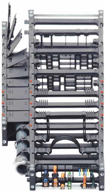
253 506 -ChainSystems
254 Overview E-Chains Designing page 528,Color, materials, tempera , tures from page 565,Harnessing with......readychain page 588, Zipper E-Chain page 574,Zipper E-Tube page 620, Easy Chain page 596,System E1 page,...,e2/000 page 654,...,E2 R page ,.....,TwisterChain page 820,......,Steel Trough page Quick Selection......select your E-Chain page 510,Contents by Series and page page 524,Series in ascending E2 micro page ,E2 mini page 642 sequence page 525,... E2 R100 page 680,... E4 kit page 694,E4/00 page 696,E4/4 page 718,E4/light page ,... System E3 & E6 = Low noise!,system E3 page 744,System E6 page Triflex R......for robot applications page 774,Easy Triflex page 782,Triflex page 788 "Super-Alu"-Trough page ,... Chainfix saddle clamps,chainfix saddle clamps, page 826 stainless steel page 826,Chainfix Clips page 828,Tiewrap plates page 845,... PMA Conduits page 834,PMA Connectors page 837,PMA Accesories page Preselection Contents by product, Series and page Contents by Series in ascending sequence Design- and calculation aids Applications Material data Fax-Forms and Glossary of Technical Terms Zip-open band with "Zipper" Quick opening and closing Easy to fit Low price Closed version and to open Chip protection Lids can be removed and swiveld-on To open from both sides Low noise Cleanroom 3-D movements Robot applications Long travels Accesories and Solutions Strain reliefs Conduits Quick Selection Quick Selection: Select your E-Chain Designing with igus E-Chains Zipper E-Chain Zipper E-Tube Easy Chain System E1 System E2 micro, mini System E2/000 medium E2 Tubes System E4 System E3 System E6 Triflex TwisterChain Guide Troughs Chainfix PMA
255 Zipper and Easy Chain Legend Standard Suitable to only a limited extent Options Especially suitable * In preperation/on request Series Inner height hi [mm] hi Inner width Bi [mm] from - to Outer height ha [mm] Outer width Ba [mm] from - to Bending radii R [mm] from - to Zipper E-Chain and E-Tubes - Lightning-fast opening and closing Zipper, zip-open along the outer radius Zipper E-Tube, zip-open along the outer radius Bi ha Ba R Pitch [mm] Unsupported fill weight max [kg/m] kg m Unsupported length max [m] , ,25 0, , , ,4 0, ,3 18,2-58, ,75 1,00 Zip-open ,5 1,5 1, , ,5 1,0 1, R07 10, , ,4 0, R ,3 18,2-58, ,75 1, R ,5 1,5 1,20 Zip-open 592 R , ,5 1,0 1, m Long travel max [m] Opening principle Quick Selection Interior separation possiblities... Separators Full-width shelves Shelves ESD/ATEX Clean-Room UL-V2 Low noise Price index Page Easy Chain - easy to fit - simply press cables in Easy Chain, split crossbar along the outer radius Easy Chain, split crossbar along the inner radius E ,7-13, ,23 0, E ,7 0,28 0, E045 9, , ,25 0,40 To fill from 604 E06 10, ,5-22, ,45 0,55 outer radius 606 E08 14, ,3 18,2-58, ,75 1, E ,5 0,5 0, E200 24, , ,0 1, E , ,4-120, ,0 1, E ,5-115, ,5 0,75 1, E26 36, ,0 2, E , ,0 2, E , ,0 2, E300 48, ,0 2, E , ,0 2, E , ,0 2, Z045 9, , ,25 0, Z06 10, ,5-22, ,45 0, Z08 14, ,3 18,2-58, ,75 1,00 To fill from 608 Z ,5 0,5 0,65 inner radius 610 Z200 24, , ,0 1, Z , ,4-120, ,0 1, Z ,5-115, ,5 0,75 1, Z26 36, ,0 2, Z , ,0 2, Z , ,0 2, Z300 48, ,0 2, Z , ,0 2, Z , ,0 2, System E1 - Modular, 1-piece strip design for simple applications E * 625 E * 625 E * To fill from 625 E * outer radius
256 E2 micro, mini and E2/000 Legend Standard Suitable to only a limited extent Options Especially suitable * In preperation/on request Series Inner height hi [mm] Inner width Bi [mm] from - to E2 micro - one-piece E-Chains - small sizes hi Bi Outer height ha [mm] ha Outer width Ba [mm] from - to Ba Bending radii R [mm] from - to R Pitch [mm] Unsupported fill weight max [kg/m] kg m Unsupported length max [m] ,7-13, ,24 0, ,7 0,375 0, , , ,25 0,40 Non ,375 0,50 snap-open , , ,48 0, ,3 18,2-58, ,74 1, E2 mini - one/two-piece E-Chains - small and medium sizes E2 mini, non snap-open ,5 1,5 1, m Long travel max [m] Opening principle Quick Selection Interior separation possiblities... Separators Full-width shelves Shelves ESD/ATEX Clean-Room UL-V2 Low noise Price index Page E2 mini, snap-open along inner radius E2 mini, snap-open along outer radius ,5 0,5 0, B15i 17, ,5 1,5 1, Snap open along inner radius B15 17, ,5 1,5 1, B , ,5 1 1, Snap open along outer radius E2/000 E-Chain - two-piece E-Chains - the E2 standard! E2/000, snap-open along inner radius ,5-138, ,3 2 1, , , Snap open along , inner radius 670 Non snap-open E2/000, snap-open along outer radius ,5-138, ,3 2 1, , , Snap open along , outer radius 670 E2/000 "half" Energy Tube, snap-open along inner radius ,2-119, ,8 2,0 1, ,5-138, ,3 2 1, , , Snap open along , inner radius 672 E2/000 enclosed E-Tube, snap-open along inner radius ,5-63, ,3 2 1, , , Snap open along , inner radius
257 E2 Tubes and E4/00 Legend Standard Suitable to only a limited extent Options Especially suitable * In preperation/on request Series Inner height hi [mm] Inner width Bi [mm] from - to E2 R100 - two-piece E-Tube - swivel-on lids E2 E-Tubes, hinged, snap-open along inner radius hi Bi Outer height ha [mm] ha Outer width Ba [mm] from - to Ba Bending radii R [mm] from - to R Pitch [mm] Unsupported fill weight max [kg/m] kg m Unsupported length max [m] Quick Selection R ,5 1,5 1, R ,0 2, R ,8 10,0 2,50 Snap open along 684 inner radius m Long travel max [m] Opening principle Interior separation possiblities... Separators Full-width shelves Shelves ESD/ATEX Clean-Room UL-V2 Low noise Price index Page E2 E-Tubes, hinged, snap-open along outer radius R ,5 1,5 1, R ,0 2, R ,8 10,0 2,50 Snap open along 684 outer radius E2 R - two-piece E-Tubes - small pitch R ,3 1,0 1, R ,3 8,0 2, R ,0 2,50 Lids to open 690 from outer radius E4/00 - the standard - E4 modular system E4/00, with crossbars every link E4/00, with crossbars every other link ,5 4,0 2, ,0 2, ,0 2, To open from ,0 3, both sides ,0 4, ,0 7, ,0 7, ,0 8, ,0 8, ,0 2, ,0 3, ,0 4, To open from ,0 7, both sides 710 E4/00, E-Tube - fully enclosed R ,0 2, R ,0 2, R ,0 3, Lids can be 706 R ,0 4, removed and 708 R ,0 7, hinge-opened
258 E4/4, E4/light and E3, E6 Legend Standard Suitable to only a limited extent Options Especially suitable * In preperation/on request Series Inner height hi [mm] hi Inner width Bi [mm] from - to Outer height ha [mm] Outer width Ba [mm] from - to E4/4 - Speciality: High stability "on the side" - Very long travels E4/4, with crossbars every link E4/4, with crossbars every other link E4/4, E-Tube - fully enclosed Bending radii R [mm] from - to Pitch [mm] Unsupported fill weight max [kg/m] Unsupported length max [m] Quick Selection ,0 2, ,0 3, ,0 4, To open from ,0 6, both sides ,0 2, ,0 3, ,0 4, To open from ,0 6, both sides 728 R ,0 2, R ,0 3, R ,0 4, Lids can be removed and 726 R ,0 6, hinge-opened 728 E4/light - Speciality: Light weight - low price E4/light, with crossbars every link E4/light, with crossbars every other link E4/light E-Tube - fully enclosed Bi ha Ba R kg m ,0 4, ,0 4, ,0 4, To open from ,0 5, both sides ,0 4, ,0 4, ,0 4, To open from 738 both sides R ,0 4, R ,0 4, R ,0 5, Lids can be 740 hinge-opened E3-3-piece E-Chain, high Dynamics - quiet and smooth E ,7 0,30 0, E ,7 0,70 0, E ,7 0,85 1,20 Zip-open 752 E6 - Six-piece E-Chain - for extremely Low-Noise Operations E6, crossbars every other link E6 Tube, crossbars every other link 516 E ,0 1, E ca. 2, E ,00 80 To open from 764 E , both sides 768 E6.80L , E , R ,0 ca. 1, R ca. 3, m Long travel max [m] Opening principle Lids can be removed on both sides Interior separation possiblities... Separators Full-width shelves Shelves ESD/ATEX Clean-Room UL-V2 Low noise Price index Page 517
![Triflex Legend Standard Suitable to only a limited extent Options Especially suitable * In preperation/on request Series Inner height hi [mm] Inner width Bi [mm] from - to Outer height ha [mm]](/docs-images/86/94432175/images/259-0.jpg "Triflex R - 3-D E-Chain for Robot Applications Triflex, R closed design and TwisterChain hi Bi ha Outer width Ba [mm] from - to Ba Bending radii R [mm] from - to R Pitch [mm] Unsupported fill weight")
259 Triflex Legend Standard Suitable to only a limited extent Options Especially suitable * In preperation/on request Series Inner height hi [mm] Inner width Bi [mm] from - to Outer height ha [mm] Triflex R - 3-D E-Chain for Robot Applications Triflex, R closed design and TwisterChain hi Bi ha Outer width Ba [mm] from - to Ba Bending radii R [mm] from - to R Pitch [mm] Unsupported fill weight max [kg/m] kg m Unsupported length max [m] Quick Selection TRC ,3 778 TRC ,4 778 TRC.70 71,5 71, ,8 Closed 778 TRC ,3 95, ,7 778 m Long travel max [m] Opening principle Interior separation possiblities... Separators Full-width shelves Shelves ESD/ATEX Clean-Room UL-V2 Low noise Price index Page Triflex R, "Easy" design for fast installation of conduits TRE ,3 778 TRE ,4 778 TRE.70 71,5 71, ,8 Easy to fill 778 TRE ,3 95, ,7 from both 778 sides Easy Triflex - for 3-D motion - Simple filling from 2 Sides Triflex - for 3-D motion - closed Triflex, closed design Triflex, zu open E ,5 786 E E Easy to fill 786 E from both 786 E ,5 sides 786 E E E , Cosed , Lids to open TwisterChain - for circular and spiral Movements Fill weight max [kg/m] ,5-112, ,5 1, ,0 1, ,0 1,8 360 To open from ,0 2,5 360 both sides
![igus Guide Troughs - for Long Travels Guide Troughs for long travels Series Outer height Can be used in the following igus E-ChainSystems Materials of side parts Preisindex Page Trough side part [mm]](/docs-images/86/94432175/images/260-0.jpg "Super-Alu-Trough, Basic Version - For general machinery Quick Selection 971.30.SL / 971.31.SL 87 E2/000: 2400/2450/2480/2500 E2 medium: 255 E6: E6.29/R6.29 Aluminium 810 972.30.SL / 972.31.SL 117 E4/00: 280/290/R770 E4/4: 2828/2928/R7728 E6: E6.")

260 igus Guide Troughs - for Long Travels Guide Troughs for long travels Series Outer height Can be used in the following igus E-ChainSystems Materials of side parts Preisindex Page Trough side part [mm] Super-Alu-Trough, Basic Version - For general machinery Quick Selection SL / SL 87 E2/000: 2400/2450/2480/2500 E2 medium: 255 E6: E6.29/R6.29 Aluminium SL / SL 117 E4/00: 280/290/R770 E4/4: 2828/2928/R7728 E6: E6.40 Aluminium SL / SL 117 E2/000: 2600/2650/2680/2700 E2 Rohre: R58 Aluminium SL / SL 144 E2/000: 3400/3450/3480/3500 E2 Rohre: R68 E4/00: 380/390/R780 E4/4: 3838/3938/R7838 E6: E6.52/R6.52 Aluminium SL / SL 184 E4/00: 400/410/R880 E4/4: 4040/4140/R8840 E4/light: 14040/14140/R18840/14240/14340 E6: E6.62 Aluminium 818 Speciality: Steel Guide Trough - For harsh environments / E2/000: 2400/2450/2480/2500 E2 medium: 255 E6: E6.29/R6.29 Galvanized steel / Stainless steel on request / E2/000: 3400/3450/3480/3500 E2 Rohre: R68 E4/4: 3838/3938/R7838 E4/00: 380/390/R780 E6: E6.52/R6.52 Galvanized steel / Stainless steel on request / E4/00: 400/410/R880 E4/4: 4040/4140/R8840 E4/light: 14040/14140/14240/14340 E6: E6.62 Galvanized steel / Stainless steel on request / E2/000: 2600/2650/2680/2700 E2 Rohre: R58 Galvanized steel / Stainless steel on request / E4/4: 5050/5150/R9850 E4/light: 15050/15150/R19850 E6: E6.80/E6.80L Galvanized steel / Stainless steel on request / E4/00: 280/290/R770 E4/4: 2828/2928/R7728 Galvanized steel / Stainless steel on request / E4/00: 600/601/R608/640 E4/light: 1640/R1608 Galvanized steel / Stainless steel on request / E4/00: 220/R760 Galvanized steel / Stainless steel on request E2 mini: 10/B15 Zipper: 15 Galvanized steel / Stainless steel on request

![top/bottom saddle clamps and two stacker saddle clamp ø [mm] from - to page 6-42 826 6-34 826 6-22 826 PMA Cable Protection Product PMAFLEX Conduits - Cable Protection Description Contents PACO](/docs-images/86/94432175/images/261-1.jpg "Flexible, medium, divisible 834 TN Divisible connectors, PG 834 GTN Divisible lock nuts, PG 834 PCL Very flexible, medium 835 VOH Pliable, very heavy 835 PIS/PIH Highly flexible, medium 836 CYL Very")

261 Strain Reliefs Strain Relief Product Chainfix Clamps - Maximum pull forces Single clamp housing, including top/bottom saddle clamps Double clamp housing, incl. top/bottom saddle clamps and one stacker saddle clamp Triple clamp housing, incl. top/bottom saddle clamps and two stacker saddle clamp ø [mm] from - to page PMA Cable Protection Product PMAFLEX Conduits - Cable Protection Description Contents PACO Flexible, medium, divisible 834 TN Divisible connectors, PG 834 GTN Divisible lock nuts, PG 834 PCL Very flexible, medium 835 VOH Pliable, very heavy 835 PIS/PIH Highly flexible, medium 836 CYL Very flexible, medium 836 page Chainfix Stainless-Steel* - Maximum pull forces Single stainless steel*-clamp housing, including top/bottom saddle clamps Double stainless steel* clamps for two cables incl. mating trough and double trough (*Material stainless steel: ) Chainfix Clip - High pull forces, plug-in PMAFIX Connectors - Safety and Sealing Systems Modular, detachable strain relief, fast installation without the need for tools Engages reliably in the C-Profile Tiewrap Plates - For cable tiewrap universal, bolted or clip-on IP66 - static, IP54 dynamic Universal safety clip IP68 - static, IP67 dynamic Oval clip PMAFIX Connectors PMAFIX Connectors VW 90 elbow, metric & PG PMAFIX Connectors VN Straight, metric & PG PMAFIX Connectors VA 45 elbow, metric & PG PMAFIX Connectors VB 90 curved elbow, metric & PG PMAFIX Connectors VO Flange 90 PMAFIX FH0 One-piece system support Separate component, either bolted onto a KMA bracket, snap-in connection Clip-on tiewrap plates with no bolts that are inserted/removed with a screwdriver Clip-on tiewrap plates for attachment to the opening crossbars Tiewrap Plates with Cable Tiewraps Tiewrap Plates - clip-on for C-profiles PMA - Acessories Tiewrap Plates with Clip-On Connection for the C-Profile Clip-on tiewrap plates for opening crossbars PMA MN Hexagonal Lock Nuts, metric & PG 844 PMA SGB Tube clamps 845 PMA 514 Plug Screws, metric & PG
262 Contents...by Product, Series and Page 1 Quick Selection, Content Tables, Pictograms Overview Quick Selection Pictograms Designing with E-Chains igus ReadyChains - Harnessing Introduction Designing with igus. 528 igus terms in alphabetical order Calculation of E-Chain - lengths and camber. 531 Solutions/ Applications. from 532 Unsupported - Short travel applications... from 534 Unsupported - Noise- Optimized Load diagrams FL G / FL B..... from 538 Gliding - Long Travel 3 Zipper E-Chains Applications Vertical - Hanging Applications "Zig-zag" - Hanging Applications Vertical - Standing Applications Side-Mounted Applications Rotary Motion Applications Cable and Hose Packages Cables and Hoses in E-Chains Zipper - zip-open E-Chains and zip-open E-Tubes Easy Chain E E E045/Z E06/Z E08/Z Easy Chain and System E1 E2 micro E2 micro, mini and E2/ Zipper E-Tubes R E14/Z E200/Z E16/Z E26/Z E300/Z E2 mini B15/B15i B E2/ / E2 Energy Tubes Series R100 and Series R E2 Tubes Series R100 R117/R R157/R R167/R E2 Tubes Series R R Strain Relief Elements 558 Technical Data and Standards Technical Environment 560 ESD/ATEX Cleanroom Certificates Material Data and Colors Chemical resistance. 566 ReadyChains Ready-made E-ChainSystems Fax-Forms R R R System E1 E E E E / / / / / / / R R E4/ /R /290/R /390/R /410/R /601/R System E4 E4/00, E4/4, E4/light E4/4 2828/2928/R /3938/R /4140/R System E3 & System E6, Extremely low-noise operation Introduction E3 & E Sysem E3 E E E System E6 E R E R, Easy Triflex 2 Triflex, Triflex, TwisterChain Triflex R TRC/TRE TRC/TRE TRC/TRE TRC/TRE Super-Alu-Trough / / / / / Guide Troughs: Super-Alu and Steel Trough Steel Trough 92.30/ / / / / igus Strain Reliefs Chainfix Clamps Chainfix Stainless Steel Clamps PMA Conduits Conduits PACO PCL PIS/PIH VOH CYL Easy Triflex E332/E Triflex 332/333/352/ Chainfix Clip Tiewrap plates..universal for C-Profil Connectors PMAFIX VWD PMAFIX VND PMAFIX VAD PMAFIX VBD PMAFIX VOD /5150/R E4/light 14040/ / / /R E R E E6.80L E Twister Chain 2208/2808/ 3808/ / / / Acessories PMACLIP FHO Lock Nuts Tube Clamps Plug Srews Overview igus E-Chains...by Series in Ascending Sequence Series Product page Series Product page Series Product page 03 E2 micro TwisterChain 800 E6.40 System E E2 micro E4/4 724 E6.52 System E E2 micro E4/4 724 E6.62 System E E2 micro TwisterChain 800 E6.80 System E Zipper E4/4 726 E6.80L System E E2 micro E4/4 726 R07 Zipper Zipper E4/4 728 R09 Zipper E2 mini E4/4 728 R117 E2 Tubes E2 mini E4/light 734 R118 E2 Tubes Zipper E4/light 734 R15 Zipper Zipper E4/light 736 R157 E2 Tubes E2 micro E4/light 736 R158 E2 Tubes Zipper E4/light 738 R1608 E4/ E4/ E4/light 738 R167 E2 Tubes E4/ Triflex 792 R168 E2 Tubes E2 medium Triflex 792 R17 Zipper E4/ Triflex 792 R18840 E4/light E4/ Triflex 792 R19850 E4/light E4/ Triflex 792 R48 E2 Tubes E4/ Triflex 792 R58 E2 Tubes E4/ Triflex 792 R608 E4/ E4/ Triflex 792 R68 E2 Tubes E4/ Triflex 792 R760 E4/ E4/ B15 E2 mini 650 R770 E4/ E4/ B15i E2 mini 650 R7728 E4/ E4/ B17 E2 mini 652 R780 E4/ E4/ E03 Easy Chain 600 R7838 E4/ E2/ E04 Easy Chain 602 R880 E4/ E2/ E045 Easy Chain 604 R8840 E4/ E2/ E06 Easy Chain 606 R9850 E4/ E2/ E08 Easy Chain 608 TRC.100 Triflex R E2/ E1 System E1 620 TRC.40 Triflex R E2/ E14 Easy Chain 610 TRC.60 Triflex R E2/ E16 Easy Chain 614 TRC.70 Triflex R E2/ E200 Easy Chain 612 TRE.100 Triflex R E2/ E26 Easy Chain 616 TRE.40 Triflex R E2/ E3.10 System E3 748 TRE.60 Triflex R E2/ E3.15 System E3 750 TRE.70 Triflex R E2/ E3.22 System E3 752 Z045 Easy Chain E2/ E300 Easy Chain 618 Z06 Easy Chain E2/ E Easy Triflex 786 Z08 Easy Chain TwisterChain 800 E Easy Triflex 786 Z14 Easy Chain E4/4 722 E Easy Triflex 786 Z16 Easy Chain E4/4 722 E Easy Triflex 786 Z200 Easy Chain E2/ E Easy Triflex 786 Z26 Easy Chain E2/ E Easy Triflex 786 Z300 Easy Chain E2/ E Easy Triflex E2/ E6.29 System E

263 Pictograms E-ChainSystems Dimensioning E-ChainSystems Accessability of E-Chains and E-Tubes Icon-bar Cannot be opened Zipper principle: Zip to open Snap-open along inner radius Snap-open along outer radius Easy Chain -principle: simply press cables in Pictograms kg Recommended Standard igus - Information igus Order examples igus Web Weights C igus - Definition Preferred Series Part No key Temperature Acceleration / Speed Can be opened from both sides Snap-open along outer radius on left or right side Snap-open along inner radius on left or right side Can be opened from one side Can be opened from both sides and hinged open on one side Unsupported - short travels Gliding - long travels Vertical hanging application Vertical standing application Side-mounted application Series Inner height [mm] System Contact E-Chains Interior Seperation System E6 IInner height: 80 mm Determining size Interior height hi [mm]: The largest cable which is to be accommodated determines the minimum interior height. Interior width Bi [mm]: The number of the cables to be contained determines the width. Unsupported length Twice the value of the unsupported length determines the maximum travel in the "unsupported" type of operation. For evaluation the weight of the cables to be carried must be known, then an exact evaluation can be made using a diagram on the introductory page of the selected product. Quicklinks Quicklinks for more information and additional features on each page. "Visit" directely your chosen product online - for example and you ll find more details, 3D-CAD-files, DXF-files, PDF-downloads, application examples and many more for your chosen igus product. Fill weight [kg/m] FL G FL B Unsupported length FL B / FL G [m] Length of travel S [m] Price Index Calculation Low noise! ESD-Certificate IPA Cleanroom- Certificate Torsional movements UL- Approval if-design Award Other Cleanroom-Certificate Rotary motion application Horizontal and vertical application Nested application Side by side application Mounting bracket Strain Relief Guide Though Assembly Instruction Page Legal Information The information in this catalog, and the data in the Design section in particular, is based on our current knowledge of the products described. No legally binding assurance in respect of characteristics or suitability for a specific intended application can be derived from it. igus is unable to assume liability of any nature for damage, loss or injury resulting from application of the products. We recommend that you always check suitability of the products for a specific intended application in a practically-oriented test. Please consult igus. For reasons relating to ongoing technical developments, we reserve the right to implement technical modifications and improvement of the products at any time. Subject to printing errors. The terms "igus", "ReadyChain", "Chainflex", "E-ChainSystems", "E-Chain", "Energy Chain Systems", "E-Chain", "Flizz", "Easy Chain", "TwisterChain, "igubal, "iglidur", DryLin" and "Polysorb" are legally protected trademarks in the Federal Republic of Germany and in case also in foreign countries. 526 Low price category Medium price category Highest price category 527


264 Designing with igus Table of Contents Introduction Designing with igus... from page 529 igus Terms in Alphabetical Order... page 530 Calculation of E-Chain -Lengths and Camber... from page 531 Applications with igus E-ChainSystems... from page 532 Unsupported - Short Travel Applications... from page 534 Unsupported - Noise-Optimized... page 537 Load diagram unsupported Straight FL G /unsupported Sag FL B... from page 538 Gliding - Long Travel Applications... from page 542 Vertical - Hanging Applications... page 546 "Zig-zag" - Hanging Applications... page 547 Vertical - Standing Applications... from page 548 Side-Mounted Applications... from page 550 Rotary Motion Applications... page 552 Cable and Hose Packages... from page 554 Strain Relief Elements... page 558 Technical Environment... from page 560 Standards and Certificates... page 564 Material Data and Colors... from page 565 ReadyChains - Ready-Made E-ChainSystems... from page 567 Fax-Forms... from page 570 Designing with igus Design About igus E-ChainSystems igus E-ChainSystems guide and protect moving cables and hoses on automated equipment. They can be used in a wide variety of applications and possess the following capabilities: Use with various types of motion and travels Guidance of sensitive bus and data cables, as well as LWL, using the same techniques as with electric, gas, air and liquid hose guidance Long service life under very high loads and demanding requirements Smooth operation in a full range of environments and climates. On the following pages, we offer important guidelines which are to be taken into consideration when designing safe Energy Chain Systems. All specifications are based on test results from the igus laboratory and our field experience since Simply fill in the "igus system design" fax sheet on page 570, log onto the igus web site at igus.de and us your technical specifications, or call us. We will provide a comprehensive quote by the end of the next business day. Laboratory and practical experience Our calculations and analyses are based on the result of ongoing practical tests in our Technical Center and our experience with gliding applications. The focal points of our tests are pushpull forces, friction values and abrasion under widely varying conditions and speeds, as well as factors such as dirt, weathering or impact and bumps. We test all system components such as cables, hoses, strain relief and other accessories, in addition to the E-Chains or E- Tubes and Guide Troughs. igus factory in Cologne The igus test laboratory for E-Chains and Chainflex cables
265 Designing with igus igus Terms in Alphabetical Order Calculation of E-Chain -Lengths and Camber Designing with igus Application-Icons On looking through and handling of these catalog, Calculation of E-Chain lengths you will find the following terms and formula: If the fixed end of the Energy Chain is located in the center of the travel, the E-Chain length "L K " is igus E-ChainSystems Unsupported - short travels Gliding - long travels Vertical hanging Short cut Describtion α = The rotation angle of the rotating machine element [ ] M = Deviation of the center point [mm] a = Acceleration [m/s 2 ] AR = Outer radius, E-Chain [mm] Ba = Outer E-Chain width [mm] Bi = Inner E-Chain width [mm] B Ra = Guide trough outer width [mm] B Ri = Guide trough inner width [mm] D = Over length E-Chain radius in final position [mm] D 2 = Over length for long travels gliding [mm] calculated by using half the length of travel and adding the value "K" for the curved length. (You can obtain the value "K" from the tables in the catalog.) Placing the Fixed End in the center of the travel is the most cost-effective solution because it requires the shortest Energy Chain, cables and hoses. L K = S / 2 + K This formula is generally valid for all types of applications if the fixed end is in the center of the travel. Exceptions: rotary movements and most long travels. S S/2 S/2 The fixed end in the center of the travel is the most favor-able solution Design FL B = Unsupported length with sag [m] Vertical standing Side-mounted Rotary motion Horizontal and vertical FL G = Unsupported straight lenght [m] FL U = Unsupported lower run [m] FZ max = Maximum additional load [kg/m] H = Nominal clearence height [mm] ha = Outer E-Chain height [mm] H F = Required clearance height [mm] hi = Inner E-Chain height [mm] H Ra = Outer trough height [mm] H Ri = Inner trough height [mm] IR = Inner radius, E-Chain [mm] K = Add-on for bending radius (K is taken from the data tables of the individual igus Series) [mm] K 2 = Further add-on if the mounting bracket location is set lower (for long travels) [mm] R L K = S / 2 + M + K This formula is valid if the fixed end is outside the center of the travel. S S/2 S/2 L K =E-Chain length S =Length of travel R =Bending radius M=Deviation from the center point K =π R + "safety" Add-on for bending radius (K is taken from the data tables of the individual igus Series H =Nominal clearance height H F =required clearance height L K = E-Chain length [mm] n = Number of links [1] R n Mon = Number of installation sets (left/right) [1] Nested n Ri = Number of trough-sets (left/right) [1] Side by side R = Bending radius [mm] RBR = "Reverse bending radius [mm] S = Length of travel [mm] S / 2 = Half length of travel [mm] T = Pitch [mm] v = Speed (travel) [m/s] X 1 = Inner machine-construction space (TwisterChain ) [mm] Camber Camber is the curve of the upper run along its unsupported length. All igus Energy Chains are manufactured with camber, special "no camber" E-Chains on request. The camber allows for longer M "No Camber" - Special "NC" E- Chains with no camber also available. Please consult igus. Combined motions X 2 = Outer radius chain, including clearance (TwisterChain ) [mm] unsupported lengths and increases service life and operating safety. In the Installation Dimensions section of each respective Energy Chain description, you will find the measurement H F, which specifies the Necessary clearance height - necessary clearance height, taking the camber into account. Upon request, we can deliver Energy depends on the camber of the E- Chains without camber for restricted space applications; however, these "no camber" chains do not have Chain. Find values for the neces- Formula Describtion the same load-bearing capacity. Please consult igus. sary clearance height "H F " on each product page. 2 FL B = Calculation of maximum travel length, unsupported with sag 2 FL G = Calculation of maximum travel length, unsupported straight B RI Ba + 5 = Calculation of the minimum guide trough width H RI 2 ha = Calculation of the minimum guide trough height K = π R = Add-on for bending radius L K = S/2 + M + K = Calculation of chain lengths For all types of applications, fixed end is outside the center of travel L K = S/2 + K = Calculation of chain lengths For all types of applications, fixed end in the center of travel, except rotary movements and most long travels L K = S/2 + K + K 2 = Calculation of chain lengths for long travels, fixed end in the center of travel Principle of camber for igus E-Chains H F = required installation height H H F Diagrams unsupported length from page Application-examples and more information online visit our homepage at: Application-examples and more information online visit our homepage at: 531


266 Designing with igus Solutions with igus E-ChainSystems Solutions with igus E-ChainSystems Designing with igus igus E-ChainSystems Long travels (441 m) with igus Rol E-Chain Long travel applications page 542 High fill weights (60 kg/m) with System E4. Fill weights/load diagrams page 538 Multi-axis E-Chains Easy Triflex on a production line, combined movements page 549 Unsupported application System E4, up to 50 m/s speed page 534 Unsupported, side-mounted E4 Series R188 page 550 Unsupported application System E4 page 534 Design ReadyChain under water. System E4 and Chainflex CF9, ReadyChain page 567 ReadyChain with combined motions on tooling machines page 549 Series E6.52 high speed (15 m/s) low noise operation, optimized noise level page 537 Gliding application System E4, up to 500 m realized page 542 Gliding, side-mounted Series E4/4 page 550 Gliding application System E4 page 542 Crash test unit: 22 m/s speed and 784 m/s 2 acceleration, Travel speed page 534 Complex movements with igus Triflex R, combined movements 532 Clearoom and Triflex R Technical Environment page 560 Vertical, standing Series E4/light, up to 6 m possible page 548 Rotary movement System E4 page 552 Vertical, standing Series E4/light page 548 Extension links for E2 and E4 for large conduits, Cable and Hoses page 554 Zig-zag movements, 36 m height with E4/4. Zig-zag movements page 547 igus System E6 - High acceleration and ESD safety, ESD & ATEX page 561 Vertical, hanging Series E4 up to 40 m possible page 546 Spiral and rotary movement TwisterChain page 552 Combined movement Series Triflex page More application-examples and detailed information online visit our homepage at: More application-examples and detailed information online visit our homepage at: 533


267 Designing with igus Unsupported - Short Travel Applications Unsupported - Short Travel Applications Designing with igus Unsupported applications igus E-ChainSystems Unsupported If the upper run of the E-Chain operates without touching the lower run over the entire travel, it is called an "unsupported" application. Unsupported length The distance between moving end and the beginning of the radius curve of the E-Chain is called the "unsupported length." It is always dependent upon the type of E- Chain and the fill weight. The "FL G " type of installation always generates the longest service life and can be operated with the max. values for speed and acceleration. Example for unsupported straight FL G HF R H The "unsupported" application is the most common. igus E- Chains are very well suited for high dynamics and long service life. Unsupported length The maximum unsupported length is dependent upon the fill weight and the type of E- Chain or E-Tube. As a result, we differentiate among three types of unsupported length: 01) Unsupported with straight upper run FL G The "FL G " E-Chain applies when the upper run either has camber, is straight, or has a maximum of mm sag, depending on the size of the chain. The "FL G " type of installation is always preferred. The E-Chain runs quietly and is not exposed to any additional vibration. 02) Unsupported with permitted sag FL B The "FL B " E-Chain applies when the sag amounts to more than mm, depending on the chain size, and less than a defined maximum sag. This maximum sag is dependent on the type of chain. The "FL B " application is technically permissible in many cases. It becomes problematic if the acceleration and the travel frequency are high. 03) "Critical sag" S If the sag is greater than permissible for "FL B ", then we refer to it as "critical sag." An installation with critical sag must be avoided or reserved for extreme circumstances. An E-Chain should never be installed with critical sag. There are applications which, after a very long period of use, reach the stage of "critical sag." The E-Chain or E-Tube should be replaced at that time. Please contact us if your application reaches critical sag! Example of unsupported permissible, FL B What to do if the unsupported length is insufficient If your application, fill weight and travel fall outside the "unsupported length" parameters of the desired E-Chain, you have the following options: Select a more stable igus E-Chain Support the E-Chain in the unsupported area (this possibility has restrictions for acceleration, speed and noise as a consequence - three fundamental examples are detailed to below - please consult igus if you are considering this possibility - we will gladly provide you with a detailed proposal) Use a "multiband" chain or "nest" two E-Chains inside one another (please consult igus regarding these options) Design the travel distance as a "gliding application". R 1/6 S 2/6 S Series 28 with support of the "FL B " area R 1/4 S 1/4 S Design 2 x R 2 x R FL G S 2 HF R H S FL B S 2 Unsupported Length For every igus E-Chain or E- Tube, you will find the values for "FL G " and "FL B " in two locations: On the following pages in this chapter as an overview and within every individual series chapter. These values are essential for: Finding a suitable Energy Chain for your fill weight and travel distance Identifying the maximum load for the selected E-Chain. Diagrams unsupported length from page 538 The following important factors should be considered to select the correct E-Chain : Unsupported length Speed Acceleration Service life Load bearing areas Noise level Technical environment Support of the "FL G " area. The overall "straight, unsupported travel" can be increased along the upper run by a maximum of 50% of the FL G and along the lower run by a maximum of 100% Support of the "FL B " area. The overall travel distance can be extended to a maximum of 100% from FL B 534 More application-examples for short travel applications visit our homepage at: More application-examples for short travel applications visit our homepage at: 535

![[m/s 2 ] 20 6 a peak [m/s 2 ] 784 Standard value of FL G service life: 10 million cycles We recommend locking mounting brackets as standard if high speeds or accelerations > 20 m/s 2 Preferred Series](/docs-images/86/94432175/images/268-1.jpg "for max.")
, dependent on acceleration FL B service life Z in millions of cycles 15 10 5 7 6 5 0 0 2 4 6 8 Acceleration a [m/s 2 ] Standard")

268 Designing with igus Unsupported - Short Travel Applications Unsupported - Noise-Optimized Designing with igus igus E-ChainSystems Standard values of max. speed and acceleration: Unsupported FL G FL B v max. [m/s] 10 3 v peak [m/s] 20 a max. [m/s 2 ] 20 6 a peak [m/s 2 ] 784 Standard value of FL G service life: 10 million cycles We recommend locking mounting brackets as standard if high speeds or accelerations > 20 m/s 2 Preferred Series for max. speed and acceleration System E6 page 754 System E3 page 744 Zipper page 574 Series 255 page 674 E4/00 page 696 FL G service life Z in millions of cycles Acceleration a [m/s 2 ] Standard values on service life for FL G, (unsupported, straight), dependent on acceleration FL B service life Z in millions of cycles Acceleration a [m/s 2 ] Standard values on service life for FL B (unsupported, sag), dependent on acceleration Different surfaces and guide troughs are possible Speed, acceleration and service life For unsupported applications, the acceleration a, is the critical parameter. High acceleration can cause the E-Chain to vibrate and reduce its service life. This is a particular danger if the E-Chain already has a sag greater than the FL G value. Max. values for acceleration, speed and service life are achieved only with E-Chains incorporating the FL G design. FL G designed E-ChainSystems can sustain very high loads. To date, a peak acceleration of 784 m/s 2 has been achieved during continuous use. Through ongoing testing in the igus laboratory and from practical experience, standard values for service life have been formulated. Our tests confirm that these standard values apply to all igus E-Chains and E-Tubes. It is crucial to determine whether the application will be designed as unsupported straight FL G or unsupported, with sag FL B. Load-bearing surfaces Unsupported E-Chains normally require some type of surface on which the lower portion of the E- Chain runs. A wide range of configurations is available, as the drawings on the right demonstrate. Many material options are feasible: Metals, polymers, stone, wood, concrete, glass, etc. We also have solutions to minimize the noise generated by the chain s lower portion. Please consult igus. When selecting the running surface, be sure dirt and debris cannot collect in the E-Chain path. Minimize noise levels with igus E-ChainSystems The igus program offers you optimal noise-reduction E-Chains. The table below briefly illustrates the differences in noise level among various E-Chains. In addition to the E-Chain, the running surface, the dynamics and the cable and hose package play a role in overall noise generation. Have our specialists design the quietest E-ChainSystem for your application, for example: System E4-46 db(a) A measurement by the Rhineland Technical Inspection Authority (TÜV Rheinland) for System E4/101, Series indicates a value of 46 db(a) at 1,5 m/s with an unsupported length. System E6 46 db(a) A measurement conducted by the Rhineland Technical Inspection Authority (TÜV Rheinland) in May 2002 indicates a value of 46 db(a) at 2 m/s and with an unsupported length of 1.5 m with Series E , and all this with at least 10 db(a) sound pressure level generated by external noise. A reduction of 3 db(a) sounds like a 50% reduction in the noise level to the human ear We have received an official comment from the Rhineland Technical Inspection Authority (TÜV Rheinland Berlin Brandenburg) and we are able to provide you with a copy on request Design FLU We recommend pivoting mounting brackets as standard! Unsupported lower run E-Chains without support along the lower run have restricted use. The value FL U usually must be determined in a test by igus. The maximum permissible amount of the projection depends on the fill weight, the selected E-Chain, the dynamics, and other factors, because the various combinations of these parameters can produce very different results. If the lower run of the E-Chain cannot be supported over the whole travel, please consult igus. Mounting brackets We recommend pivoting mounting brackets as standard for unsupported applications. Pivoting mounting brackets compensate for the camber, can be installed more easily and decrease the load on the first E-Chain link in operation. Exception: If the acceleration is greater than 20 m/s 2 or if the height is limited to the H F measurement, locking mounting brackets keep the E-Chain under the H F measurement. System E4 partially unsupported - please consult igus regarding this type of configuration System E3 - low-noise, 38 db(a) Long-term tests in the igus acoustic laboratory showed reduction of db(a) compared with standard EnergyChains, measured at a speed of 1.8 m/s and an acceleration of 3 m/s 2. Figure determined in the igus laboratory in accordance with DIN 45635, taking into consideration background noises, for the Series E Selected noise tests - External noise corrected measurement values E-Chain System Averaging of the corrected Test method Series sound pressure levels igus Series E3.22 E3 38 db(a) unsupported 1,8 m/sec. igus Series E6.52 E6 46 db(a) unsupported 2,0 m/sec. igus Series 221 E4/ db(a) unsupported 1,5 m/sec. igus Series 255 E2 medium 53 db(a) unsupported 1,5 m/sec. igus Series E-Band E-Band 59 db(a) unsupported 1,5 m/sec. igus Series 280 E4/00 64 db(a) unsupported 2,0 m/sec. igus Series 381 E4/ db(a) gliding 3,0 m/sec. Chain 1 Third-party product 77 db(a) unsupported 2,0 m/sec Chain 2 Third-party product 68 db(a) unsupported 2,0 m/sec Chain 3 Third-party product 73 db(a) unsupported 2,0 m/sec Source: TÜV Rheinland, exept Series E Source igus laboratory Preferred igus E-Chains for minimizing noise System E3 page 744 System E6 page 754 E4/101 page 696 E4/00 page 696 Series 255 page 674 Easy Chain page 596 Series R58 page 688 Series R68 page More application-examples for short travel applications visit our homepage at: More information about noise optimized E-Chains and test results at: 537
269 Designing with igus Unsupported Straight FL G - small, medium E-Chains FL G - Load diagram use unsupported - short travels Unsupported Sag FL B - small, medium E-Chains FL B - Load diagram use unsupported - short travels Designing with igus FL G FL B igus E-ChainSystems Fill weight - Weight of all cables and hoses, including contents (for media hoses) within the E-Chain, typically given [kg/m] FL G - recommended unsupported E-Chain with straight upper run FL B - unsupported E-Chain with permitted sag These values are essential for: Finding a suitable E-Chain for your fill weight and travel distance Identifying the max. load for the selected E- Chain The maximum travel -always amounts to 2 x "FL G " if the fixed end is in the center of the travel. In this case, the following applies: E-Chain length: L k = S / 2 + K H F 2,0 1,9 1,8 1,7 1,6 1,5 1,4 1,3 1,2 1,1 1,0 0,9 R H S S 2 H F 2,0 1,9 1,8 1,7 1,6 1,5 1,4 1,3 1,2 1,1 1,0 0,9 R H S S 2 To the right of the FL B graph of the diagram, the application is shown in "critical sag", which must be avoided! If you cannot meet your application demands using these parameters, keep in mind these specifications are conservative maximum values. In individual cases, they can be exceeded by up to 30%. Special solutions are also possible. Please consult igus You will find both diagrams for each Series listed individually in the catalog Design S = Length of travel R = Bending radius H = Nominal clearance height H F = Required clearance height K = π R + "safety" Add-on for bending radius (K is taken from the data tables of the individual igus Series 0,8 0,7 0,6 0,5 0,4 E3.15 E3.22 0,8 0,7 0,6 0,5 0,4 E3.22 0,3 0,3 Diagram Series: Triflex page 788 Easy Chain page 596 System E3 page 744 Zipper page 574 E2 micro page 626 E2 mini page 642 Fill weight [kg/m] 0,2 0,1 E ,1 0,3 0,5 0,7 0,9 1,1 1,3 1,5 1,7 1,9 0,2 0,4 0,6 0,8 1,0 1,2 1,4 1,6 1,8 2,0 m Unsupported length FL G [m] Length of travel S [m] 0 0,2 0,4 0,6 0, m Fill weight [kg/m] 0,2 0,1 E3.10 E ,1 0,3 0,5 0,7 0,9 1,1 1,3 1,5 1,7 1,9 Diagram Series: 0,2 0,4 0,6 0,8 1,0 1,2 1,4 1,6 1,8 2,0 m Unsupported length FL G [m] Triflex page 788 Length of travel S [m] Easy Chain page 596 System E3 page 744 Zipper page ,2 0,4 0,6 0, m E2 micro page 626 E2 mini page Find the values for "FL G " and "FL B " also in every individual Series chapter! Find the values for "FL G " and "FL B " also in every individual Series chapter! 539
270 Designing with igus Unsupported Straight FL G - large E-Chains FL G - Load diagram use unsupported - short travels Unsupported Sag FL B - large E-Chains FL B - Load diagram use unsupported - short travels Designing with igus FL G FL B igus E-ChainSystems Fill weight - Weight of all cables and hoses, including contents (for media hoses) within the E-Chain, typically given [kg/m] FL G - recommended unsupported E-Chain with straight upper run FL B - unsupported E-Chain with permitted sag These values are essential for: Finding a suitable E-Chain for your fill weight and travel distance Identifying the max. load for the selected E- Chain The maximum travel -always amounts to 2 x "FL G " if the fixed end is in the center of the travel. In this case, the following applies: E-Chain length: L k = S / 2 + K S = Length of travel R = Bending radius H = Nominal clearance height H F = Required clearance height K = π R + "safety" Add-on for bending radius (K is taken from the data tables of the individual igus Series H F R / H 800/840 S S 2 H F R /14240 H 800/840 S S 2 To the right of the FL B graph of the diagram, the application is shown in "critical sag", which must be avoided! If you cannot meet your application demands using these parameters, keep in mind these specifications are conservative maximum values. In individual cases, they can be exceeded by up to 30%. Special solutions are also possible. Please consult igus You will find both diagrams for each Series listed individually in the catalog Design 2 2 1,5 1,5 Diagram Series: Easy Chain page 596 E2/000 page 654 E2 Tubes page 676 E4/00 page 696 E4/4 page 718 E4/light page 730 E6 page 754 Fill weight [kg/m] 1 0,5 0 0,5 1 1,5 2 Unsupported length FL G [m] 2,5 3 3,5 4 4,5 5 5,5 6 6,5 Length of travel S [m] m 8 m Fill weight [kg/m] 1 0,5 0 0,5 1 1,5 2 Unsupported length FL G [m] 2,5 3 3,5 4 4,5 5 5,5 6 7 Length of travel S [m] m 8 m Diagram Series: Easy Chain page 596 E2/000 page 654 E2 Tubes page 676 E4/00 page 696 E4/4 page 718 E4/light page 730 E6 page Find the values for "FL G " and "FL B " also in every individual Series chapter! Find the values for "FL G " and "FL B " also in every individual Series chapter! 541


271 Designing with igus Gliding - Long Travel Applications Gliding - Long Travel Applications Designing with igus Long travel applications Gliding applications principle The illustrations below shows the gliding igus E-ChainSystems Gliding application - If the upper run of the E-Chain rests on the lower run, it is a gliding application Over 400 m travel For long travels, the upper run of the igus E-Chains rests on the lower run. The upper run glides partially on the lower run and partially at the same height on a glide bar. We recommend that igus calculate every gliding application for you. We will always offer the most cost-effective application priciple. For lateral guidance, a Guide Trough is necessary. If the stationary mounting bracket and the fixed end of the cables and hoses can be placed in the center, the E-Chain length is calculated as follows: Depending on the technical data and the selected Energy Chain, the mounting point of the moving end of the Energy Chain must be lowered on some units Lowered mounting height. In our system analysis for long travels, we give exact details for Advantages lowered moving end: Space saving Longer travels possible Higher servie life due to less wear Design 5 m/s speed solution, taking the technical your specific application. Fill weights up to 70 kg/m requirements and operating safety into consideration. The Our calculations and analyses are based on the result of ongoing practical tests in our Technical Center and our experience with gliding applications! We test all system components such as cables, hoses, strain relief and other accessories, in addition to the E-Chains or E- Tubes and Guide Troughs. Conveyor belt in quarry. Gliding application with travel distance of 179 m, travel speed 67 m/min. and fill weight 8 kg/m Advantages for long travel applications with igus E-Chains Travels over 400 m Gliding speeds up to 5 m/s (more in individual cases) Service life of 10 years and more with igus Energy Chain Systems Further advantages of the design are: Many different types of cables and hoses can operate side by side in the same system (i.e. electrical, data, fiber optic cables with hydraulic and pneumatic hoses) Space-saving installation Quiet operation High accelerations Durable in wind, weather, dirt, and chemicals Simple assembly of the modular system on the spot Rapid assembly and replacement of cables and hoses Trends in long travel applications system solution designed by us can be also given an igus system guarantee. H1 Example of lowered mounting height S S/2 S/2 D2 K2 Guide trough with glide bar Guide trough without glide bar Total length of guide trough The function of an E-ChainSystem for gliding applications (schematically) The fixed end of the E-Chain is located in the center of the travel distance R R HRi E-Chain length: L k = S / 2 + K S = Length of travel R = Bending radius H Ri = Trough inner height H F = Required clearance height K 2 = Further add-on if the mounting bracket location is set lower (specified by igus ) New developments are currently being tested: Travels up to 800 m. We break through the 400 m barrier by means of special components. Please ask us for more specific information Long travel systems "off the reel." Complete costum-made E-ChainSystems - with cables, connectors, S S/2 S/2 K = π R + "safety" Add-on for bending radius (K is taken from the data tables of strain relief - are delivered on the reel and "rolled off" into the pre-assembled Guide Troughs, K2 the individual igus Series directly. Travel distances up to 100 m are delivered this way today, with longer travels possible R R D 2 = Over length for We have recently extended this technology to large Energy Chains and currently offer travels up to 400 m Total length of guide trough (without glide bars) For a configuration involving two opposed Energy Chains, the travel is measured as shown and selected when these factors apply: Restricted space High loads HRi long travels gliding Guide trough Glide bar Long travel "off the reel." Up to 100 m travel pre-assembled and ready to install Preferred igus E-Chains gliding, long travels Rol E-Chain page 718 System E4 page 692 E2/000 page 654 Ship to shore crane, Malaysia. Travel distance of 441,3 m realized with the igus Rol E-Chain Series 5050R Mobile camera, Olympic Games in Atlanta, S = 100 m, v = 10 m/s in push-pull operation Robotics: quiet running, high acceleration, up to cycles per day, E4/4 chapter 7 Gliding applications = Pivoting mounting brackets 542 Information about Rol E-Chain, AUTO-GLIDE and Flizz visit our homepage at: More application-examples for long travel applications visit our homepage at: 543


272 Designing with igus Gliding - Long Travel Applications Gliding - Long Travel Applications Designing with igus igus E-ChainSystems Guide troughs are used for for long travels, (travels from 5 to 10 m) and greater, depending on the chain type. They allow igus E- Chain and E-Tubes to continue smooth, low-friction operation in these long-travel situations. Various guide trough-systems are available Guide Troughs, page 804 If the fixed point is in the center of the travel, use half of the guide trough with glide bars... and the other half of the guide trough without glide bars Ba = E-Chain outer width ha = E-Chain outer height H Ri = Inner trough height B Ri = Inner trough width H Ri 2 ha B Ri Ba + 5 Guide trough Glide bar Installation set ha ha ha B Ri Ba B Ri Ba Glide friction values for igus E-Chains made of igumid G and various glide bars HRi Demonstration: Guide troughs without glide bars - upper run glides on the lower run. HRi Guide troughs The guide trough is an important element in long travel applications. Usually, the height of the trough must be at least twice that of the E-Chain link height. The sides must provide a chamfered opening. The trough inner width is the same as the E-Chain outer width, plus 5 mm (B Ri = Ba + 5). Along the side of the trough, where the upper run cannot glide on the lower run, glide bars must be installed. We recommend the use of polymer glide bars from igus. They are optimally matched to the E-Chain material and achieve the lowest values for friction, noise and wear. Guide troughs with and without glide bars can be obtained for almost all igus E-Chains. Important: When assembling the trough parts, the following points must be given particular attention: Properly align all trough parts upon installation All screw heads should be flush with the trough Smooth levelled transition between the end of the E-Chain and the glide bars Solid connection with the glide surface. These points must be observed when using assembly-friendly igus guide troughs. Demonstration: Guide troughs with glide bars. We recommend the use of polymer glide bars from igus made of igulen. They are optimally matched to the E-Chain material and achieve the lowest values for friction, noise and wear. igumid G igus polymer Glide Anodized Stainless special bar igulen sheet steel aluminum steel Friction value 0,19 0,45 0,54 0,48 dynamic Source: igus laboratory Travel speeds and accelerations Travel speeds up to 5 m/s in continuous operation are possible and in use on current applications. In special cases, even higher speeds are possible. For example, igus E4/00 and E4/4 E-Chains achieve speeds of 22 m/s and accelerations of 784 m/s 2 in crash test units. (Only a few thousand cycles per year are required in this situation.) Acceleration plays a large role in the calculation. Differentiations must be made between normal operational acceleration and a sudden jolt of acceleration such as unexpected stops or so-called "E-stops." Even in these situations, igus E-Chains prove to be very durable. Service life We offer service life calculations for your application based on our extensive gliding application experience. As developers of polymer plain bearings, we possess vast material behavior knowledge which we apply to the development of E-Chains as well. Units with 200 m travels have been in operation for 8 years with minimum maintenance. Units up to 60 m travels have been in operation for 12 years with almost no maintenance. (Please consult igus for references and calculations for your project.) The maintenance-free aspects of igus E- ChainSystems over long periods and under rough operating conditions is often the deciding factor in choosing igus. Our system guarantee (depends on Automated storage/retrieval system with System E2 and the application) provides additional peace of Chainflex cables - travels up to 80 m and speed of 4.5 m/s mind. Technical environment Long travel applications using igus Energy Chains run in water, in dirt, in the tropics, in explosion risk areas (with special design features) and many other conditions. Guide troughs can be supplied in corrosion-free materials. You will find more details in the Technical Environment section of this chapter. Calculation Comprehensive tests place us in the position of knowing our products precisely. Important factors in these tests are: Push-pull forces under both ambient and extreme temperatures Humidity and dirt Friction values of the polymers, alone and against various glide surfaces Behavior of electrical conduits under push-pull conditions Behavior of hydraulic and media hoses under pushpull conditions Service life, and noise generation. If we cannot in fact calculate your application based on these factors, we will perform a practical test for you in our laboratory. Please consult igus. E4 in a pre-cast concrete plant with dust and concrete sediment Technical data - long travels Travel max 400 m (800 m) Travel speed max 5 m/s Travel acceleration max dependent on calculation, can be 50 m/s 2 and more Fill weight maximum dependent on calculation, can be 70 kg/m and more Corrosion-free guide troughs are available in the material: Normally galvanized Stainless steel Seawater resistant aluminum Special properties - Long travel applications E-Chains that are nested can be used in gliding applications. This type of installation is most often used when there is a width restriction. Guide troughs with special wall heights are necessary E- Chains running side by side, or in a "multiband" design can also be used in gliding applications. Higher fill weights often require special guide troughs which can be delivered either from stock or on short notice We have also developed standard parts for unconventional solutions involving large hoses in gliding applications. Nested, gliding E-Chains "Multiband" E-Chain Large hose elements Design 544 More application-examples for long travel applications visit our homepage at: More application-examples for long travel applications visit our homepage at: 545


273 Designing with igus Vertical - Hanging Applications Vertical - Hanging Applications Designing with igus Vertical, hanging applications In accordance with the principle of "hanging" igus E-ChainSystems We recommend locking mounting brackets for hanging applications. In restricted spaces, other solutions are possible with consultation Safe strain relief and clear separation of the conduits are the basic prerequisites for hanging installations - Cables must be able to move freely and bear their own weight In most cases, vertical motion applications do not require lateral guidance applications, heights of over 100 m are possible with igus E-Chains. Chains with interior separation allow many different types of conduits to operate together in the same system without becoming entangled. Cables and hoses Two important factors in vertical hanging applications are how the conduits lay in the E-Chain and and how they are secured at the end points: All cables and hoses must be hung so that they bear their own weight. The Energy Chain fulfills the function of orderly conduit bundling only and should not absorb any further tensile forces igus interior separation elements should be used for distinct division of all cables and hoses The cables and hoses must be secured carefully to both end points of the Energy Chain The strain relief must be designed so that the opposite run cannot catch. Camber A normal igus E-Chain with camber is suitable for hanging use if enough space is available. If there is no room - as is frequently the case for storage and retrieval systems in narrow aisles - a "no camber" E-Chain must be ordered. Order example: NC (NC = no camber) These versions are offered at no additional charge, but with a slightly longer delivery period - usually 1-2 business days longer. Hanging and standing E-ChainSystems can reach Hanging assembly with to very different points one-sided U profile "Zig-zag" design The modular design of igus E-Chains facilitates this space-saving and unconventional solution. For modern platform technology, such as performance stages, a variety of conduits which adjust the stage height must be accommodated. Lack of space almost invariably presents particular difficulties. The photo below shows an E-Chain in a "Zig-zag" configuration produced by incorporating reverse bend radii or "RBR". The unextended E-Chain is stored in a "basket" underneath the stage. If the stage is raised, the E-Chain unfolds, generating little to no noise. This construction is possible with System E4/4 E- Chains as well as many other types. Please consult igus for these kinds of applications. Design Vertical motion without lateral acceleration If the application involves vertical motion without lateral acceleration, the A B Lateral acceleration can occur in two directions - guidance is necessary E-Chain can be installed without lateral support. If the space restrictions are severe, an igus E-Chain with no camber must be specified. Vertical motion with lateral acceleration If lateral acceleration occurs, lateral guidance of the E-Chain must be provided in most cases. The diagram to the right shows the principle of such guidance. Partial guidance is also an option; however, it must at least cover the area in which the E-Chain may sway. Lateral acceleration can occur in two directions. The lateral guidance must be installed accordingly. If you have a choice, the layout in Figure A is preferred. Additional guidance along the side of the E-Chain helps to stabilize the chain further. igus "zig-zag" space-saving solution - stroke heights of over 20 m are possible Preferred Series for vertical, hanging design E4/00 page 696 E4/4 page 718 E2/000 page 654 E2 Tubes page 676 Technical data - vertical hanging Travel height max: 100 m v max: 20 m/s dependent on height and stability of the E-Chain a max: 50 m/s 2 dependent onheight and stability of the E-Chain Principle of a hanging E- Chain with lateral guidance - lateral accelerations in both directions are intercepted With the Energy Chains of the Systems E4, "Zigzag" solutions can be realised quickly and cost-effectively without special parts Preferred Series for "Zig-zag" design E4/4 page More application-examples for hanging applications visit our homepage at: More information and application-examples for zig-zag applications at: 547


274 Designing with igus Vertical - Standing Applications Vertical - Standing Applications Designing with igus igus E-ChainSystems We recommend locking mounting brackets for standing applications Cables must be able to move freely and bear their own weight Standing application with support of the first E-Chain links - R68 Energy Tube page 690 Mounting brackets The mounting brackets must be attached so that the Energy Chain cannot bow out. The igus program offers locking or one-sided, locking mounting brackets for almost all types of Energy Chains. Locking KMA mounting brackets are highly recommended because they can be attached flush to the machine. U-shaped supported E-Tube for high lateral acceleration Lateral acceleration If lateral acceleration occurs, the E-Chain should be supported along the outer radius. For higher E-Chain heights, it is generally recommended that at least the first three links on the outer radius be supported. For maximum heights and weights, the whole distance must often be supported. Due to the wide variety of combinations involving weights, stroke heights, E-Chain types and bending radii, we strongly recommend you make use of our consulting services. Options for a standing application with support of the first E-Chain links: on the right, with U-shaped guidance - on the left, with the support of the first chain links For higher E-Chain stroke heights, it is generally recommended that at least the first three links along the outer radius be supported. For maximum heights and strokes, the whole E-Chain must often be supported. With lateral acceleration, the E-Chain must be supported and, depending on the direction of this acceleration, be guided along the side Design Cables and hoses Cables and hoses must be laid in the E-Chain so that they can bend freely For precise guidance of the cables and hoses, we strongly recommend igus interior spacer modules Cables must be strain relieved at both ends Combined movements Combined vertical and horizontal movements are possible with igus Energy Chains for a cost-saving solution. Locking KMA mounting brackets Series 4040 E4/4 page 726 Preferred Series for vertical, standing applications E4/00 page 696 E4/4 page 718 E2/000 page 654 E2 Tubes page 676 Technical data - vertical - standing applications Max. stroke height - without support Max. stroke height - with support of the first E-Chain links Max. stroke height - with full support v max (dependent upon stroke height and weight) a max (dependent upon stroke height and weight) 4 m 6 m 20 m 20 m/s 50 m/s 2 Combined horizontal and vertical movements 548 More application-examples for hanging applications visit our homepage at: More application-examples for hanging applications visit our homepage at: 549


275 Designing with igus Side-Mounted Applications Side-Mounted Applications Designing with igus Long travel, gliding Side-mounted E-Chains can travel over 100 m with igus E-ChainSystems Side-mounted E- Chains - are strongly recommended if the installation height is restricted. adequate guidance. All E-Chain types are designed to operate gliding on their side. The corresponding glide surface is usually an igus polymer, stainless steel or galvanized steel, depending on how high the demands on the travel speed and service life are. Roller and ball bearings or additional gliding elements are not necessary for igus Energy Chains. The diagram below shows the principle of a guide trough for side-mounted applications. For a side-mounted gliding application, we recommend locking mounting brackets. The Energy Chain is then pushed straight through the guidance Cables and hoses must be able to bend freely Design Standard values for unsupported lengths, sidemounted, upon request. The unsupported lengths can be extended by supporting the links next to the mounting brackets System E4 Energy Tube in direct chip area E4/light page 730 Short travels with or without support igus E-Chains placed on their side can be used unsupported to a limited extent. The turned "unsupported length" in this case is dependent on the following factors: Fill weight Width of the E-Chain Bending radius Parallel placement. The greater the fill weight of the E-Chain, the shorter the available unsupported length. When placed on its side, the E-Chain width, in effect, becomes the height. As this "height" increases, the E-Chain System becomes proportionally more stable. Small bending radii provide greater stability. If further movement in a second axis is added to the parallel motion of two chains, the unsupported length is impaired. For applications with low fill weight, the standard mounting brackets are adequate. If, however, the fill weight is high and the travels are long, the E-Chain must then be supported either in whole or in part. Due to the variety of application possibilities, we strongly recommend you make use of our consulting services. igus - Series E4/4 with partial support Cables and hoses Cables and hoses must be guided so that the E- ChainSystem can move freely at all times. The igus modular separation options offers numerous possibilities, such as vertical separators and spacers, to keep these conduits separated and bending freely for maximum service life. igus will gladly provide an application analysis, free of charge. A Cable and hose guidance with separators and spacers C D B A-B C-D Unsupported System E4 E-Chain E-Chain, side-mounted, supported E4/4 Principle of a guide trough for long travel, side-mounted Preferred Series for sidemounted applications E4/00 page 696 E4/4 page 718 E2 Tubes page More application-examples for side-mounted applications visit our homepage at: More application-examples for side-mounted applications visit our homepage at: 551


276 igus igus igus igus igus igus igus igus igus igus igus igus igus igus igus igus igus igus igus igus igus igus igus igus igus igus igus igus igus igus igus igus igus igus igus igus igus igus igus igus igus igus igus igus igus igus igus igus igus igus igus igus igus igus igus igus igus igus igus igus igus igus igus igus igus igus igus igus igus igus igus igus igus igus igus igus igus igus igus igus igus igus igus igus igus igus igus igus igus Designing with igus Rotary Motion Applications Rotary Motion Applications Designing with igus igus E-ChainSystems Options 2. and 3. for rotary movements require less installation height. The E-Chains glide mostly on surfaces made of polymer, stainless steel or steel and are guided through channels into a rotary movement. (See "side mounted" for further design tips.) Bending radii, circular radii and E-Chain widths are variable with this product line Preferred Series for rotary motion applications TwisterChain page 796 All "RBR" E-Chains System E4 page 692 System E2/000 page 654 igus igus igus Rotary motion with a "standard" E-Chain End of travel Stationary part Beginning of travel Example of a rotary motion using RBR. Here, the outer ring rotates. The inner ring could rotate just as well 1. Rotary motion with TwisterChain The TwisterChain product line offers the biggest selection for rotary movements. TwisterChain solutions are particularly recommended for spacerestricted applications such as articulated robots, revolving tables, etc. Further details can be found TwisterChain page Rotary motion with standard Energy Chains The photo to the right shows an application which was achieved using "standard" E-Chains (in this case, standard means that the E-Chain only bends in one direction). Such solutions are possible if a great deal of space is available and if the angles of rotation are limited to a maximum of 450. All igus E-Chains / E-Tubes and Chainflex cables are appropriate for this situation. 3. Rotary motion with an "RBR" Energy Chain "RBR" is "reverse bending radius" and means that the E-Chain can bend in two directions. Each igus E-Chain can incorporate RBR designs, with the exception of several radii, for the E-Tubes R117 to R9850 and for the Series 07, 09, 14, 15, and 17. The RBR does not necessarily need to be identical to the normal bending radius of an E-Chain. For example: Part No /425.0, describes a Series 280 E- Chain with an inner width of 150 mm, standard bending radius of 100 mm and RBR of 425 mm. Most rotary motions can be achieved with the RBR option. Angles of rotation up to 540 have been realized. Below is an example of rotary motion using an RBR E-Chain. Please consult igus for your particular application. Guide troughs Depending on the dynamics and load of the application, the guide troughs are made of steel or stainless steel. For applications with a high cycle frequency, we suggest coating the guide troughs with polymer. igus E-Chains require no additional gliding elements for contact with the base or sidewalls. igus offers complete systems including guide troughs, but we are pleased to offer support with drawings for your own construction. Product range E-Chains with "RBR" are available as standard from stock for the complete Triflex range. In addition, we supply a number of E-Chains which are equipped as standard with "RBR". For all other types, "RBR" means custom-made, and we will be more than willing to offer you this option. igus E- Chains with "RBR", available as standard Easy Triflex /Triflex, page 782. Rotary motion with RBR, diameter 6000 mm, with RBR, the inner ring rotates Table of "RBR" E-Chains available from stock Guide troughs for rotary motion applications Many igus E-Chains are available with "RBR" -reverse bending radius. Please note the information text of the relevant Series in the product range Example: /220 RBR Radius Width Series The E-Chain Series appearing on the right table are "RBR" - versions available from stock. Almost all igus E- Chains can be delivered as a "RBR"- version. Please contact us for any special inquiry Design Standard E-Chain , angle of rotation 225 Series 255 with 360 RBR rotary motion on a robot Part No. Series from page Part No. Series from page /018 E2 micro /048 E2 mini /018 E2 micro /220 E2 mini /018 E2 micro /028 E2 mini /090 E2 micro /600 E2 mini /028 E2 mini /048 E2 mini /600 E2 mini /400 E2 mini /048 E2 mini /220 E2 mini /220 E2 mini /150 E4/ /028 E2 mini /150 E4/ /600 E2 mini 646 E /038 Easy Chain /048 E2 mini 646 E /038 Easy Chain /220 E2 mini 646 E /038 Easy Chain /028 E2 mini 646 E /038 Easy Chain /600 E2 mini 646 Technical data rotary motion: max. angle of rotation = 540 (larger angles possible) v max. = 10 m/s a max. = 20 m/s More application-examples for rotary motion applications visit our homepage at: More application-examples for rotary motion applications visit our homepage at: 553


277 hi ha Designing with igus Cable and Hose Packages Cable and Hose Packages Designing with igus igus E-ChainSystems Rules for: Maximum conduit diameters Separation Bending radius Electrical cables need at least 10% reserve space all around, hydraulic hoses 20% Ba Bi The maximum conduit diameter is specified for each Series on its respective page Modular E-ChainSystems solves all known requirements for interior separation Maximum cable and hose diameters The maximum cable and/or hose diameter corresponds to the inner height of the selected E-Chain / E-Tube, with additional minimum clearance. This minimum clearance would be, for example, 10% for electrical round cables, 20% for hydraulic hoses. An E-Chain is ideal if a minimum lateral gap to the next cable or hose has been factored in. Depending on the nature of the cables, the dynamics, and the expected service life, more clearance must be allowed. In specific cases, clearances may be altered further. Please consult igus. Distribution within the E- Chain Cables and hoses with very different diameters should be laid separately. The separation is achieved using modular separators Cables and hoses must under no circumstances have the opportunity to tangle. Therefore, the clearance height of a compartment with several similar cables or hoses next to one another must not amount to more than one and a half times the cable/hose diameter. General rules for cables and hoses in E-Chains Supply of data and energy in all forms within an E-Chain- System. The key advantage of an igus E-ChainSystem is the safe accommodation of various forms of data cables and energy suppliers in one system. We recommend the optimal separation layout of the conduits in the E-Chain, but you, the customer, are still afforded the final choice. It is possible, for instance, to maintain minimum distances Hydraulics and electric cables are between bus and motor cables separated from one another in this example and mix pneumatics, electric and hydraulics in the same compartments. In addition to the quality of the cables used, the arrangement of each conduit within the E-Chain and the space allowed, are important for the service life of the system. Various separation options enable the adaptation of the E-Chains to the specific requirements of each respective application. General rules of thumb, such as "maximum 80% of the cross section of an E-Chain should be used" are no longer viable with today s application complexities. In this chapter, we give you detailed recommendations. Due to the variety of the application parameters, we strongly recommend you take advantage of our free consultation services. Simply give us a list of your cable requirements (or merely the required electrical or other services) and you will receive our recommendation by the end of the next business day. Neatly laid cables with igus interior separation D1 D1 + D2 > 1,2 x hi 10% min 2 mm 10% min 1 mm d1 + d2 1,2 x hi 10% min 1 mm D2 10% min 1 mm 10% min 2 mm Clearance space "all around" for round electrical cables Bending radius R d1 d2 d1 + d2 1,2 hi 10% min 1 mm The reason for the distribution rules are as follows The cables and hoses must be laid so that they can move freely at all times and so that no tensile force is exerted at the radius of the E-Chains. For high-speed applications and high cycles, cables or hoses must not be laid on top of each other without horizontal separation. The standard values for this are: Travel speed over 0.5 m/s and cycles over 10,000 p.a. igus interior separation offers a safe solution for this situation. Further guidelines for distribution The cable or hose weight should be symmetrically distributed along the width of the E-Chain Cables and hoses with different outer jacket materials must not be allowed to "stick" together. If necessary, they must be laid separately. All igus Chainflex cables can be combined with each and other brands of cable or hose The cables and hoses should always be fixed at the moving end. The fixed end should always involve strain relief. Exceptions are made only for certain hydraulic hoses with length compensation issues or other high pressure hoses (i.e. hydraulic hoses) Generally, the faster and more frequently the E-Chain operates, the more important the exact positioning of the cables and hoses inside the chain. Due to the wide variety of the possibilities, we strongly recommend you take advantage of our free consultation services for your specific applications The bending radius of our E-Chain depends on the "thickest" or "stiffest" cable or hose in your application The bending radii of the E- Chains should be adjusted to the recommendations of the cable or hose manufacturer. The selection of a larger radius than the minimum will positively affect service life The specification of minimum bending radii for cables and hoses refers to use at normal temperatures; other bending radii may be recommended. Please ask your cable or hose supplier for details Chainflex cables permit the smallest bending radius of 5 x d for one million strokes. The igus program offers up to to 12 different bending radii from stock. Distribution rules D1 + D2 > 1,2 x hi Rule 1 - If D1 + D2 > 1.2 x E- Chain inner height, no separation between the two cables/- hoses is necessary. Two cables/oses should never be left unguided on top of one another or be allowed to become tangled. d1 + d2 1,2 x hi Rule 2 -If d1 + d2 1.2 x E- Chain inner height, a vertical separator or a horizontal shelf must be used to reduce the inner height, thereby preventing the entanglement of d1 and d2. We recommend complete E*- ChainSystems - where bending radii for all cables and hoses, interior separation and service life are optimally matched. All-around clearance space in % for various cables/hoses Electrical round cables: 10 % Electrical flat cables: 10 % Pneumatics: 5-10% Hydraulics: 20 % Media hoses: % Design 554 More application-examples and detailed information online visit our homepage at: More application-examples and detailed information online visit our homepage at: 555


278 Designing with igus Cable and Hose Packages Cable and Hose Packages Designing with igus igus E-ChainSystems We will be pleased to provide you with recommendations for complete E- ChainSystems : Bending radii of all cables and hoses, interior separation and service life are then optimally intermatched. Corkscrewing: an effect of improper cable and hose place- continuous development and testing Example from igus test laboratory: ment in an E-Chain of Chainflex round electrical cables Cables must be able to bend freely. Chainflex cables can be strain-relieved directly at the mounting bracket Round electrical cables For electrical cables, the round cable is a safe, modular and cost-effective solution for E-Chain- Systems. We recommend the following criteria for selecting the proper round electrical cables: Small minimum bending radii and mounting heights Strain relief integrated directly into the mounting bracket Uncomplicated installation process - no hanging, laying out, etc, of cables Long service life at minimum bending radius Service life expectations for your application (short or long travel, hanging, etc.) Test data on service life from realistic tests Flexible shields for shielded cables Abrasion-resistant and non-adhesive outer jackets Large selection to avoid expensive custom designs. For bus cables and fiber optic cable, special attention must be paid to how effective transmission rates and shielding remain after millions of cycles at the minimum bending radius. Guidelines for the installation and strain relief of round electrical cables The cables must be laid straight, without 1twisting. Cables must not be uncoiled from the top of the spool. igus Chainflex cables are immediately ready for placement directly into the E- Chain. They need not be disconnected or laid out before installation. The cables must be laid so that each individual 2cable can move freely from side to side. The cables must be able to move freely along 3the radius. This must be double-checked if the upper run operates at the cable s maximum bending radius. 4 The division of the E-Chain s interior using shelves or igus interior separators is necessary if several cables and/or hoses with varying diameters are laid out. It is important to prevent cables and hoses from tangling. For cables and hoses with different jacket 5materials, it is important to prevent them from "sticking" to one another. If necessary, they should be separated. igus Chainflex cables can be combined with all others. Round electrical cables must be secured with 6strain relief at both ends. In exceptional cases, the cables may be fixed with strain relief at the moving end of the E-Chain only. A gap of x cable diameter between the end of the bending segment and the fixed point is recommended for most cables. Chainflex cables can, on the other hand, be secured directly to the mounting bracket with strain relief (this has been confirmed with testing). Pneumatic hoses In principle, the same rules apply for pneumatic hoses as for round cables. In practice, it has been demonstrated that pneumatic hoses are less susceptible to wear. After consultation, they can be laid together more closely than the "10% clearance all-around" rule. A double-sided strain relief is required under these conditions. For pneumatic hoses made of rubber, we recommend strictly following the "10% clearance" rule because they tend to adhere to each other and to other conduits. Fully pre-assembled E-ChainSystem with several pneumatic hoses next to and above each other Flat cables and pneumatic hoses installed in an E-Chain with full interior separation of all cables Hydraulic hoses When designing hydraulic hoses in E-Chains, special attention should be paid to the expansion of the hoses when pressurized. Sufficient room must be left in the E-Chain for this as well as the possible larger external diameter of the hoses under pressure. It is important for selected hoses to be sufficiently flexible (i.e. meet bending radius specified by the E-Chain ). The gliding ability and abrasion-resistant surface of the hoses are also important. All crossbars and shelves in the igus E-Chain minimize abrasion of hoses through wide, rounded and smooth surfaces. Normally, hoses with textile braiding are more flexible than hoses made of steel wire, while maintaining smaller outer diameters and better fatigue strength under reverse-travel Flat cables Flat cables must be able to move freely along the bending radius. Two flat cables next to one another should be kept apart with separators. If two flat cables are laid on top of one another, we strongly recommend the use of horizontal igus shelving. Flat and round cables should be laid separately in the E-Chain. Strain relief should be attached at both ends. Flat cables are only conditionally recommended for use in E-Chains. igus Energy Chains with hydraulic hoses in a tree-stripping machine stresses. As lateral movements of the hydraulic hoses within the E-Chain can lead to increased abrasion of the hose material, they should be secured in position with vertical separators, but not forced. Special "locking" separators, which grip the opening crossbars of the chain, as well as the use of "spacers," prevent lateral shifting of the separators; they also ensure the hoses stay put in cases of strong vibration and impact on the chain. Details about these accessories can be found in the description of various E-Chain types. Strain Relief - Hydraulic hoses are most often stretched lengthwise during operation. This must be taken into account when applying strain relief. More hose length is factored in to allow the hose to "breathe", or "floating" strain relief must be implemented. In some cases, one-sided strain relief on the moving end can be tolerated. Rollclip - In almost all cases, the broad, smooth and rounded surfaces of all igus E-Chains and Tubes are sufficient to protect hydraulic hoses from abrasion. In extreme cases, the igus Rollclip can be installed. The hoses come in contact with a series of polymer cylinders which rotate. "Extreme" cases include particularly soft materials, particularly narrow bending radii or highly dynamic loads. Over 95% of all applications can be solved without Rollclips. The igus program also offers polymer pneumatic hoses called: "Chainflex Air" Flat cables - Outer jackets made of rubber must be specified particularly carefully, because of potentially high static friction. Hydraulic hoses need more space: 20% all-around clearance igus Rollclip, detachable Design 556 More application-examples and detailed information online visit our homepage at: More application-examples and detailed information online visit our homepage at: 557


.")

279 Designing with igus Strain Relief Elements Strain Relief Elements Designing with igus igus E-ChainSystems Ideally, the cables/hoses should be strain relieved at both ends of the E-Chain. At the very least, they must be strain relieved at the moving end of the E-Chain. Strain relief for electrical cables Strain relief can consist of standard elements or can be custom-made. For most applications, our standard program of C-profiles with mounting brackets and space-saving Chainfix clamps can be used. We also offer simple strain relief solutions using cable tiewraps and tiewrap plates. In ideal cases, the cables should be secured at both ends of the E-Chain with strain relief (in a few instances, strain relief at the moving end of the E-Chain is sufficient - please consult igus for these cases). Strain relief in KMA mounting bracket with C-profile Features of chainfix clamps Optimal igus Chainfix housing with reduced height Long service life for dynamic applicationss thanks to improved clamping elements Integration with KMA mounting brackets - saves both time and space during installation and available for complete systems with cables and strain relief Improved housing foot clamp for easy fit into C- profile Black housing and setscrews for attractive appearance Setscrews, tightened with Allen wrench, for easy installation. Minimum gap of the strain relief and the beginning of the bending radius Tests on our premises and in field applications have shown strain relief located at the last bending point of the E-Chain has no influence over the durability of igus Chainflex cables. It is possible, therefore, to integrate the strain relief with the mounting bracket. This space-saving option for strain relief is offered by igus for almost all E-Chains. Another integrated strain relief option is the igus tiewrap plate. The mounting bracket includes comb-like plates to which cables and hoses can be secured with the help of cable tiewraps. Features and advantages: Time saving installation: strain relief is already in place when mounting brackets are bolted in Longer service life for cables/hoses when the strain relief system is implemented the cables/hoses last longer Space-saving design - strain relief at the mounting bracket almost always leaves room Ideal installation of cables in E-Chains. Chainflex cables can be directly strain-relieved in the mounting bracket (minimum gap to the last curved E-Chain link is not necessary)! Chainfix clip - modular snap-on strain relief device Chainfix clip is a series of clamps and bottom parts made of plastic for cable diameters ranging from 4 mm to 24 mm. Chainfix Clip is available for C profiles, also suitable for assembly in the KMA mounting brackets and clip-on strain relief for cross bars. Characteristic features: Quick assembly without any tools 2 and 3 layers on top of one another possible Each layer can be detached and changed later on High tensile forces in case of single-layer installation, decreasing with the number of layers For more information on all igus strain relief elements page 824 Simple strain relief with cable tiewraps attached to tiewrap plates and integrated into the mounting bracket Design The igus Chainfix range of clamps - more details: Chainfix page 824 Tiewrap plates with clip-on connection for the C-profile The plates 3050.ZC and 3075.ZC can be clipped directly into the C-profile without bolts or any extra hardware. Clip-on tiewrap plates can be released and repositioned with just a screwdriver used as a lever. Tiewrap plates as individual parts igus Chainfix strain relief in mounting bracket in practice - used here for cables and hoses Strain-relief separator Can be integrated in mounting bracket Strainrelief separator can be positioned as required Double strain relief possible Easy installation, cost-effective For Series E6.29, 2600/2700 (other Series upon request) Suitable for: Separate parts in switch cabinet construction or machine assembly Strain relief accessory for igus E-ChainSystems Attachment to mounting brackets Integration into the C- profile of KMA (polymer/metal mounting brackets) 558 More application-examples and detailed information online visit our homepage at: More application-examples and detailed information online visit our homepage at: 559


.")


280 Designing with igus Technical Environment Technical Environment Designing with igus igus E-ChainSystems Technical environment: Fire resistance Radiation Weathering Cold, heat Explosion areas Vacuum Hot chips Dirt, dust Cleanroom Chemicals Resistance to radiation igumid G is very resistant to highenergy radiation. Under gamma radiation, in the range of 8 x 10 4 rd, the mechanical properties of igumid G change very little. igumid G: UL 94 HB igumid NB: UL 94 V2 UL 94 V0 igus factory - automatic compounding and conveyor belt for igumid G Flammability of igumid G The flame-retardant characteristics of igumid G can be described using various classifications: Test aprocedure VDE 0304 parts classification llc. Tested according to UL 94 "Standard Tests for Flammability of Plastic Materials for Parts in Devices and Appliances" classification 94 HB for 3.2 and 1.6 mm thickness of the body. Tested according to DIN 4102 "Fire Behavior of Building Materials and Parts" classification materials class B-2. For further requirements, please consult igus for special solutions, such as materials with self-extinguishing properties (UL V2 or UL V0). All E-Chains (except for the Easy Chains and Series 14) are made of from igumid G. Technical environment and igumid G The igumid G material, from which igus E- Chains are made, possesses the following wide-ranging features to cope with a variety of environments: the ability to handle pressure and strenuous loads, abrasion resistance, sturdiness, stable behavior at high and low temperatures, and suitability for outdoor use. Numerous application examples, from refrigerator blocks to steel mills, prove this. In extreme cases, we also offer modifications and other igus compounds as a solution. Please consult igus. igumid G has the classification UL 94 HB. igumid NB has the classification UL 94 V2. UL 94 V0 upon request Flammability of igumid NB All Easy Chains and Series 14 Chains are made from the flame-retardant igumid NB material. These chains have the following flame-retardant classifications: UL 94 classification - V2 VDE 0304 Parts classification - llb DIN 4102 flammability of materials - B2 Please consult igus regarding material availability "V0" System E6-2nd Generation ESD Chains without pin and bores, longterm conductivity guaranteed For many years, safety in hazardous ares and ESD protection in sensitive production areas have been ESD & ATEX Special ESD products and ESD tools must be used in numerous industrial sectors in order to protect sensitive electronic components against electrostatic discharge. Consequently an electrostatic discharge function applies in particular to energy ducting systems with their central role in automated sequences. igus has developed the ESD E-Chain for these demanding applications. They are made of material igumid ESD which immediately discharges permanent electrostatic charges in controlled manner. igumid ESD consists of the igus E-Chain material which has been tried and tested for over 30 years now in millions of applications with special additives. These additives provide the required properties and, in mechanical requirements, even exceed the standard material. Thus, for instance, the somewhat higher rigidity and the approx. 15% lower density can be used to implement a longer unsupported length, depending on application. The ESD E-Chain features an even longer service life owing to the material. Unlike temporarily acting, applied conductive coatings or volatile, incorporated antistatics, the additives used provide durable and "maintenance-free" conductivity. One other advantage is the resistance to adverse ambient conditions. More ESD and ATEX information: The hue of igumid ESD approximately corresponds to RAL 7015 slate-gray igumid ESD with PTB certificate - We have received an official comment from the German National Standards Laboratory (PTB) on material igumid ESD and we are able to provide you with a copy on request Design given high priority at igus. Since 1992, E-Chains have been manufactured from our special "GC" C igumid G - UV-resistant. Temperature range from: -40 C to +130 C This robot is used for test purposes in British nuclear power plants Temperature resistance igumid G is very suitable for outdoor applications. In our experience, the mechanical properties of the E-Chain are not impaired. igumid G is also UVresistant. igus E-Chains are used in applications as cold as -40 C. Installation may be eventually compromised at temperatures below -25 C. In such cases, we offer special solutions made from coldelastic materials. 130 C continuous temperatures are possible. However, the mechanical values are reduced and the service life is impaired. Live broadcast from the Winter Olympics in Lillehammer - 75 m travel at -25 C material. Certified 12 years ago by PTB (German federal office for Physics and Technology), the material was modified in Inspite of homogenous conductivity of the material, common pin/bore design chains can hardly maintain their conductivity within normed conductivity tolerances in the long term. Constant long term conductivity values No contact surface wear Proven standard product, now also conductive Cycle life in lab test 10 Million cycles (more upon request) Underlies heightened QC procedures, with and without mounting brackets and in various install modes IPA Fraunhofer institute certifies "Level 1" discharge performance, acc. to SEMI E ESD, even for off-the-shelf standard E6 material. 560 More application-examples and detailed information online visit our homepage at: More information and certificates for ESD/ATEX products visit: 561


281 Designing with igus Safe and Clean with igus E-Chains Technical Environment - Clean Room and ESD Dirty Environment with igus E-Chains Technical Environment Designing with igus igus goes clean room - qualification of E6 and other igus E-Chains In many applications where cumbersome special solutions are used, a simple standard E-Chain can be used instead. A comprehensive test igus E-ChainSystems program was devised and performed for both gliding use and unsupported use. For many applications, the E-Chains in special materials are practically abrasion-free. Detailed test results are available upon request. IPA tests confirm that standard igus E-Chains meet clean room requirements. "Tested and certified as very good!" E-Chains for clean room applications on the test stand Clean room environments demand very high wear resistance of moving parts. E-Chains, for example, must be very wear resistant, in order to meet norm requirements for such a sensitive environment. IPA Fraunhofer Institute has tested igus Series E6 and E14 as follows: ISO class 2, as per stringent norm DIN EN ISO for Series EasyChain E at v= 1 m/s ISO class 3, as per stringent norm DIN EN ISO for System E6, Series E at v=1 and 2 m/s ISO class 4, as per stringent norm DIN EN ISO for System E4, Series at v = 2 m/s Tests with 900 C hot chips Design Test setup "Cleanroom" with E particle generation measurement Test setup "ESD" with E field strength measurement Measurement result: Particle generation E Particle >0,2µm pro min Measuring period [min] Measuring point 1 Measuring point 2 Measuring point 3 Measuring point 4 Measurement result: Field strength E Field strength [V/cm] Measuring point E-field reference strength (upon neutralisation) [V/cm] 2. Measuring result (20 hours) [V/cm] 4. Measuring result (44 hours) [V/cm] 1. Measuring result (4 hours) [V/cm] 3. Measuring result (28 hours) [V/cm] 5. Measuring result (48 hours) [V/cm] igus E-Tubes in the chip area of machine tools page 676 Splatter, hot chips Laboratory tests and numerous field applications prove that igus E-Chains and E-Tubes reliably protect cables in welding robots and machine tools. Although welding spatter leaves some visible traces, it does not impair the material or the function. igus E-Tubes have successfully withstood tests at 1,652 F (900 C) with medium-sized hot metal chips. They are in use worldwide in the chip area of machine tools (Please note: igumid G in direct contact with large amounts of melted aluminum is not recommended.). Dirt, dust, chips Materials and design make igus E-Chains excellent problem-solvers in harsh environments. Experience and application references are available upon igus E-Chains have proven their durability - request. Please consult igus with your application. shown here with wood chips Vacuum igus E-Chains made of igumid G can be used in vacuum applications. Very little outgassing occurs. igus - Experience with Dust, dirt, mud, compost, wood, textile fibers, paper dust, abrasive paste, cooling agents, glass dust, glass splinters, coal dust, sand, corundum and much more. Particularly suitable E-Chain Series for dirt, dust, chips System E4 page 692 E2 Tubes page 676 E2/000 page 654 ISO Class 2 acc. to DIN EN ISO for E Classification chart Class per DIN Equivalent to Equivalent to EN ISO VDI 2083 US Fed.Std. 209E ISO class 1 no comparable classification no comparable classification ISO class 2 no comparable classification no comparable classification ISO class 3 class 1 class 1 ISO class 4 class 2 class 10 ISO class 5 class 3 class 100 ISO class 6 class 4 class ISO class 7 class 5 class ISO class 8 class 6 class ISO Level Class 1 2 acc. ESD-compatibility to DIN EN ISO acc for to SEMI E E for E and E Classification E bei v = 1 m/s Classification E bei v = 1 m/s und v = 2 m/s Fraunhofer Institut Production technology and automation Chemical resistance igumid G is resistant to fuel, lubricants, oils, fats, alcohol, ester, ketone, and aliphatic and aromatic hydrocarbons. Oxidants and acids are damaging. The Material Data table on page 565 shows an excerpt of the precise details concerning resistance to chemicals. Acid-resistant E-Chains are available upon request. Coolant resistance E-Chains and E-Tubes have proven resistant to cooling agents. However, we are always willing to perform individual tests if you have particular problems or advanced developments. Table on resistance to chemicals page 566. Compost sludge - numerous related references available upon request 562 More information and certificates for cleanroom products visit our homepage at: More application-examples and detailed information online visit our homepage at: 563

282 Designing with igus Standards and Certificates Material Data igumid & igus E-Chain Colors Designing with igus igus E-ChainSystems Quality inspection of every E- Chain production Test location for ESD-E-Chains Chainflex cables with many certificates for e.g. DESINA Noise level tests in igus own acoustic laboratory Examples for test certificates and approvals of igus -products Certified ISO 9001 igus has been certified since November 1997 TÜV construction test igus E-Chains and E-Tubes are construction-tested by TÜV Rheinland. igus E- Chains were tested and passed by TÜV Rheinland in accordance with the valid machine guidelines. As a result, the user of igus E-Chains need not worry about meeting CE requirements through testing for this portion of the machinery. The construction test 2PFG 1036 / 10/97 for protective equipment includes the following: Application and safety Assembly Fatigue strength Resistance to external influences Sharp corners and edges ESD/ATEX igus E-Chains made of standard material igumid G correspond to the German federal office of Physics and Technology (PTB) to classification Ex II 3 GD according to ATEX-RL 94/9/EG. igus E-Chains made of igumid ESD correspond according to the German federal office of Physics and Technology (PTB) to classification Ex II 2 GD according ATEX- RL 94/9/EG. IPA Cleanroom A lot of E-Chains are suitable for the use in cleanrooms according to DIN EN ISO Confirmed by the IPA Fraunhofer Institute. UL, CSA, CEI, CE, VDE, Interbus and DESINA All igumid-materials for E-Chains and E- Tubes have got the UL-material approval. The material igumid NB has got the fire protection class approval IIb according to the test VDE 0304 Part 3/5.70, the approval V2 according UL 94 and the construction material class B2 according DIN Chainflex - cables are produced according to a lot of international standards: Interbus certification: For Interbus certification of certain CF11 bus cables. DESINA: Many Chainflex cables are Desina-compliant. Clearly quieter igus E-ChainSystems are clearly quieter. In the acoustic laboratory of the TÜV and the igus GmbH different E-Chains were compared. The igus Systems E3, E6 and E4/00 (Series E4/101) are measurably (and clearly) quieter than other products of comparable size (see also noiseoptimized E-Chains page 537) igumid The material igumid is free from toxins, according 2002/95/EC (RoHS). if Design Award 13 if Design-Awards since 1984 Material data table Units of Values Values Values Values Values Measure igumid G igumid NB igumid N igumid ESD igumid TE Yield stress Mpa 190/130 78/40 Elongation at break % 004/006 20/210 Elasticity module (tensile test) MPa 9000/ /1200 Impact strength +23 C kj/m 2 55/65/55 not broken Impact strength -40 C kj/m Ball indentation hardness H 961/30 MPa 230/ /60 Head conductivity W/k * m Ω/k * m 0,23 Dielectric constant 10 h Hz 3,9/6,2 special transitional resistance Ω*cm >10 11 >10 11 >10 12 <10 9 Impact strength density 0,6-0,8 mm kv/mm Surface resistance ROA Ω >10 11 >10 11 >10 11 <10 9 Density g/cm 3 1,37 1,14 1,14 1,2 1,02 Absorption of humidity 23/50 RF % 1,4 3,4 1,4 1,9 1,1 Coefficient of sliding friction 0,3 0,3 0,3 0,3 0,3 Fire resistance as per VDE FH2 Fire resistance as per UL 94 HB 94 V-2 HB HB HB Color RAL 9004 RAL 9004 RAL 9004 RAL 7015 RAL 9004 Maximum water absorption 5,6 7,6 7,6 7,3 Limit of elasticity in bending Mpa MPa MPa Mpa Bending strength 240 Mpa 120 MPA 110 MPa 230 Mpa Hardness Shore D Upper long-term application temperature Upper short-term application temperature Lower application temperature -40 C -40 C -40 C -40 C -30 Colors and special solutions All E-Chains made from igumid G are available in the colors listed below. Additional colors are usually feasible. Colored E-Chains are basically not available from stock. Contact igus for more information regarding colored E-Chains. All values listed apply to stability (e.g. unsupported lengths) and material characteristics for black E- Chains only. Colored E-Chains may have altered characteristics. This also applies for all E-Chains made from special materials (e.g. conductive E-Chains made from igumid GC or other special materials). "RAL" Numbers Black White Magenta Yellow Orange Red Blue Green Grey Silver-grey Grey Light grey Schist-grey Yellow/black RAL 9004 RAL 9003 RAL 4010 RAL 1018 RAL 2003 RAL 3002 RAL 5005 RAL 6011 RAL 7023 RAL 7037 RAL 7038 RAL 7035 RAL Index.0 Index.1 Index.13 Index.4 Index.2 Index.6 Index.8 Index.7 Index.3 for Chains Index.3 for Tubes Index.11 Index.14 only ESD-E-Chain Index.9 Colors for design coding Design 564 More information and certificates online visit our homepage at: More application-examples and detailed information online visit our homepage at: 565
 10 A Butyric acid 100 B Calcium chloride (aqueous) Sat. aq. sol.")
283 Designing with igus Chemical Resistance Designing with igus igus E-ChainSystems Medium Concentration igumid G Weight % and NB Acetone 100 A Formic acid (aqueous) 2 B Ammonia (aqueous) 10 A Gasoline 100 A Benzole 100 A Bitumen 100 B Boric acid (aqueous) 10 A Butyric acid 100 B Calcium chloride (aqueous) Sat. aq. sol. A Chlorinated hydrocarbons Chlorine water Sat. aq. sol. C Chromic acid (aqueous) 1 B Diesel oil 100 A Iron II cyanide 30 B Acetic acid 2 A Color A Fats, cooking A Fluorinated hydrocarbons A Formaldehyde (aqueous) 30 B Hydraulic oils A Caustic potash 10 A Potassium carbonate (aqueous) 60 A Potassium sulphate (aqueous) 100 A Methyl acetate 100 A Milk A Mineral oil A Sodium carbonate (aqueous) 50 A Oil, cooking A Oil, lubricating oil A Oleic acid 100 A Paraffin oil A Perchlorethylene 100 A Polyester resins (with styrene) A Propane gas A Mercury A Hydrochloric acid ph2 B Hydrochloric acid 2 C Hydrochloric acid 10 D Ink, printing ink A Vaseline A Tartaric acid B Zinc sulfate (aqueous) 10 A Resistance classes A: resistant B: conditionally resistant C: partially resistant D: non-resistant E: soluble Sat. aq. sol.: saturated aqueous solution Conc. aq. sol.: concentrated aqueous solution The values specified are values determined by laboratory tests and are material-specific. All specifications apply to black E-Chains. Plug-and-Play Energy Chain Systems all inclusive. igus Harnessed E-Chains since 1993 ReadyChain Design 566 More information and certificates for cleanroom products visit our homepage at: More application-examples and detailed information online visit our homepage at: 567


, patch plugs, inner partitions, connecting elements and connecting parts as requested. From easy.")

284 Designing with igus ReadyChains - Ready-Made E-ChainSystems igus - the ReadyChain Factory Designing with igus igus E-ChainSystems Increase your cash-flow immediately starting from quantity 1 - with igus ReadyChains Cut stocking cost to zero for cables, E-Chains and connectors Minimize downtime Reduce number of suppliers and purchase ordes by about 75% Reduce throughput time by about 50% Increase your cash-flow Respond flexibly to order fluctuation Cut stocking cost to zero for cables, E-Chains and connectors You can do without storage of high flexible cables, plugs and any other add-on pieces due to our rapid and guarantied delivery times. Reduce throughput time by about 50% Because of a polished logistic igus delivers ready-made systems almost worldwide within 3-10 days on the guarantied date. Respond flexibly to order fluctuation With ReadyChains you are always prepared for cyclical ups and downs. In this field you can pass the buck of capacity fluctuations to us. Minimize downtime Little things may cause big problems. Buying numerous single parts not only increases the risk of failure of your plants, it also complicates trouble-shooting. You will get a system solution with ReadyChains. Any system is checked in our test center. igus is standardized according to ISO Reduce number of suppliers and purchase ordes by about 75% One order one invoice one delivery one partner. Don t care about looking for numerous parts from numerous suppliers. We have the knowledge to pro-vide you quickly with the optimal parts. You determine the degree of harnessing 50 ReadyChain specialists use up-to-date machines for quick planning, harnessing and final inspection of your ReadyChain E-ChainSystem. Go and see for yourself: E-Chain More than 630 Chainflex Special cables for E-Chains components on stock are available for you ex stock: Design We harness from simple E-ChainSystems with inserted Chainflex cables to complex systems.these systems may include all cables and hoses (pneumatic, hydraulic), patch plugs, inner partitions, connecting elements and connecting parts as requested. From easy......to the project You determine the size Any size is possible. Because of our up-to-date production processes we can deliver fast and cost effective custom-build or serial production products. More than electrical components for patch plugs - available right away from the all-automatic high-bay warehouse Many thousand on time deliveries in customer specific transport facilities From batch size to serial production From short......to long You determine the travel length ReadyChains offers the whole spectrum of possible travels of the igus E-Chains. We harness anything from extremely short to long travels. Safe transportation guarantees damage-free delivery of all lengths. Computer-aided high-voltage testing positions ensure tested quality The all-automatic break down facility allows cheap prices for highest quality 568 More application-examples and detailed information online visit our homepage at: More application-examples and detailed information online visit our homepage at: 569
285 Designing with igus Fax-Form Fax-Order & Fax-Enquiry igus E-ChainSystems Harnessing Analysis igus E-ChainSystems with igus Designing Fax-Form igus E-ChainSystems Date: Phone: +49- (0) Fax: +49- (0) From: To: Technical Sales Energy Chain Systems Phone: P.O. Box Fax: (Porz-Lind) Date: Phone: +49- (0) Fax: +49- (0) From: To: Technical Sales Energy Chain Systems Phone: P.O. Box Fax: (Porz-Lind) Design Fax-Forms Order No. page of pages Item No. igus Order No. Number Price Chain Type Cable/hose requirements: Length Interior Separation / Vertical Separators Cable/hose layout within carrier Cable/Hose End 1 Connector End 1 Union 1 Cable/Hose End 2 Union 2 Connector End 2 We are ordering according to igus general terms of sale. The prices are exclusive of the statutory value-added tax. Delivery date: Signature/stamp
286 Designing with igus Fax-Form Project Analysis E-ChainSystems Design Layout Designing with igus Fax-Form igus E-ChainSystems Date: Phone: +49- (0) Fax: +49- (0) From: To: Technical Sales Energy Chain Systems Phone: P.O. Box Fax: (Porz-Lind) Design Fax-Forms Type of Application (check all that apply) Installation Space Travel S: mm Fixed end: Max. width permitted center of the travel yes (if applicable): H F or mm from the center R desired: Max installation height B Ri mm H F : mm S mm Guide trough? yes: if yes which Dimensions: B Ri mm Dimensions: H Ri mm Assembly point (floor, wall, console, etc.): mm Span (standard = 2 m): mm HRi Dynamics Speed: Cycles/Day: [m/s] Acceleration: [m/s 2 ] Days/Year: Ø Outer diameter: Environment Temperature [ C]: Humidity (%): Dust, dirt, chips: Special parameters: Number Manufacturer/Type, No. Conductor/AWG Ø Weight kg/m Bending Radius Cables/Hoses Further individual components desired: Energy Chains / Energy Tubes Chainflex cables/special conduits Guide trough Strain relief Harnessing On-site assembly Others Energy Chain Energy Tube To be openedon both sides Along the outer radius Along the inner radius Special requests: Please copy, fill in and fax: thank you! 572 Please supply us with as much application data as possible. Items highlighted in red must be filled out for analysis. You will receive a complete analysis with conduit layout proposal and quote by the end of the next business day. Please contact us if you have any questions. 573

287 hi ha hi ha Zipper E-Chains & E-Tubes Lightening, Fast Opening and Closing with "Zipper" Zipper E-Chains Reduced assembly-time: Zipper-like design for quick opening and closing of lids Zipper lids can be separated and joined at each chain link Small pitch for low noise, smooth operation High accelerations: 100 m/s 2 and more Interior separation possible for larger versions You find more technical data about the material, chemical resistance, temperatures chapter design, from page 565 Opening-principle Dimensioning Bending radius Part No. structure Symbol for Zipper E-Chain -Styles Selection table Bi Ba Zipper-like design Series Inner height Inner width Outer width Outer height Bending radius Unsupported page hi [mm] Bi [mm] Ba [mm] ha [mm] R [mm] length max. [m] 047 9, ,0-22,0 12, , , ,5-71,0 15, , , ,2-58,2 19, , , ,0-113,0 24, , , ,5-113,0 39, , Zipper E-Tubes against chips & dirt Fully enclosed E-Tube with zipper opening mechanism Protection against dirt and chips Superfast opening of interconnected lids Modular design - tool-free lengthening and shortening Small pitch for low noise, smooth operation, high acceleration You find more technical data about the material, chemical resistance, temperatures chapter design, from page 565 Selection table UL94-V2 - special on request R Interconnected lids Bending radius Opening-principle Dimensioning Bending radius Part No. structure Symbol for Zipper E-Tube-Styles Bi Ba Series Inner height Inner width Outer width Outer height Bending radius Unsupported page hi [mm] Bi [mm] Ba [mm] ha [mm] R [mm] length max. [m] R07 10, ,5-57,0 15, , R09 15, ,2-58,2 19, , R15 17, ,0-113,0 24, , R17 32, ,5-113,0 39, , Special features - Zipper Clean- Room Cleanroom Class 1 (ISO class 3) for Zipper Series 15, tested by the Dryden Engineering Company, California Zipper-like design R Interconnected lids Bending radius Material igumid G -40/+130 C if-design award Zipper Series R09 Material lid: igumid TE Material link: igumid G -40/+130 C Color black Radius Width Series Dirt and chip protection R Color black Radius Width Series Low-noise Zipper Zipper E-Chains Zipper E-Tubes 574 Next Page: Find application examples and assembly instructions 575


288 Zipper Applications Zipper Assembly Instructions Zipper Zipper Lightning-fast opening and closing with Zipper E-Chains and E-Tubes - "Zipper" E-Chains convince in practicality and per- igus E-ChainSystems formance. The "Zipper" function makes them a very useful product to reduce assembly time. The small pitch, the tough-elastic zipperband, and the sturdy link work wonders in high-acculeration environments. The "Zipper" Series is one of the most popular E- Chain Series in demanding industries. Typical industries & applications Pick & place robots Semiconductor machines Linear motors, actuators Machinery of all kinds Measuring equipment Machine Tools (Zipper-E-Tube) Material handling 1 2 Zipper E-Chains Zipper E-Tubes To open the Zipper - All of the lids on these E-Chains are interconnected to behave like a zipper. Grasp the lid at the end of the E-Chain and pull upward and outward To close the Zipper - Gently push the lids inward and down to snap back in place igus E-Chain Series 15 Zipper in automatic equipment - reduce assembly time if-design award Zipper Series R Zipper lids can be separated......and joined at each chain link igus E-Chain Series 17 on an X-Y table. Acceleration: 100 m/s 2 Series 15 with acceleration of 100 m/s 2 on pick-and-place robots, low noise 5 6 Zipper links are easy to separate......and to assemble
289 12,5 9 Super-Smooth Motion, Micro-Size Series 047 Zipper E-Chain Series 047 Zipper E-Chain 047 igus E-ChainSystems Pitch = 13 mm Links per m = 77 Chain length = S / 2 + K R H D K The required clearance height is H F = H + 10 mm (with 0,2 kg/m fill weight). Please consult igus if space is particularly restricted ,3 10,3 8 4 S D S/2 R Moving end (with bore) Moving end Fixed end Installation Dimensions 13 22,3 12,5 H - 12,5 Mounting Brackets H Zipper E-Chain 9 Inner height: 9 mm Very small pitch for optimum low noise, smooth motion Fill weight [kg/m] FL G Price index FL B 12,5 R "Zipper-fast" opening & closing Zipper lids can be separated and joined at each chain link Light weight Proven for high acceleration of 100 m/s 2 and more Series zip-open along the outer radius Part No. Bi [mm] Ba [mm] R [mm] Bending Radii Radii for all width! t = 1,5 t = 1, Fixed end (with pin) For Part No. Dimension B E-Chain full set [mm] B 3 3 B 30 One-piece, polymer, pivoting Full set, for both ends: Single-part order: Mounting bracket with bore Mounting bracket with pin Unsupported length [m] Length of travel S [m] max. Additional Features Unsupported length FL G = with straight upper run FL B = with permitted sag FLG HF H FLB Bi Ba Supplement Part No. with required radius. Example: Bending radii listed above can be combined with every chain width! Quicksnap - the complete, detachable mounting unit Quickfix - mounting bracket with dowel For more features see link below S (FLG) S (FLB) Part No. structure Black = standard color, other colors page 565 Bending radius Width-index Series Order example 1,0 m complete E-Chain (indicate chain-lenghts or number of links) 1,0 m (77 links) Series set mounting brackets For detailed information, PDF downloads and CAD files on this igus product For detailed information, PDF downloads and CAD files on this igus product 579
290 10,3 15 Small-Size 07 10,3 Series 07 Zipper E-Chain Series 07 Zipper E-Chain 07 igus E-ChainSystems Pitch = 20 mm Links per m = 50 Chain length = S / 2 + K R H D K The required clearance height is H F = H + 10 mm (with 0,2 kg/m fill weight). Please consult igus if space is particularly restricted (PZ) (PZ) Installation Dimensions S D S/2 Moving end Fixed end R Moving end (with bore) (PZ) 15 H - 15 H Mounting Brackets 10,3 Zipper E-Chain Inner height: 10,3 mm "Zipper-fast" opening & closing Fill weight [kg/m] Price index FL G 0.25 FL B Unsupported length [m] Length of travel S [m] Unsupported length FL G = with straight upper run FL B = with permitted sag FLG HF H FLB 15 R 8 max. Bi Ba Zipper lids can be separated and joined at each chain link Light weight and strong Small pitch for low-noise, smooth operation Proven for high acceleration of 100 m/s 2 and more Integrated strain relief option Also available as Zipper E-Tube page 588 Series 07 - zip-open along the outer radius Part No. Bi [mm] Ba [mm] R [mm] Bending Radii , ,5 Radii for all width! , , , , , ,0 Supplement Part No. with required radius. Example: Bending radii listed above can be combined with every chain width! 5,8/90 5,8/90 3,2 3, (PZ) Fixed end (with pin) : Center bores only : Outer bores only For Part No. Part No. Number Dimension A Dimension B E-Chain full set with full set without of teeth [mm] [mm] tiewrap plate tiewrap plate PZ , PZ , PZ , PZ , PZ , PZ , PZ , PZ ,0 Tiewrap plates are possible at the moving end and/or the fixed end! B A A B One-piece, polymer with or without strain relief tiewrap plates Part No. structure PZ Full set with tiewrap plate Full set without tiewrap plate PZ Full set, for both ends (with tiewrap plates) Single-part order: PZ Mounting bracket with bore, (with tiewrap plates) PZ Mounting bracket with pin, (with tiewrap plates) Additional Features S (FLG) S (FLB) Part No. structure Quicksnap - the complete, detachable mounting unit Quickfix - mounting bracket with dowel Micro Flizz - Energy guiding available on request For more features see link below Black = standard color, other colors page 565 Bending radius Width-index Series Order example 1,0 m complete E-Chain (indicate chain-lenghts or number of links) 1,0 m (50 links) Series mounting brackets + tiewrap plate PZ 580 For detailed information, PDF downloads and CAD files on this igus product For detailed information, PDF downloads and CAD files on this igus product 581
291 19,3 15 "Allrounder" Series 09 Zipper E-Chain Series 09 Zipper E-Chain 09 igus E-ChainSystems Fill weight [kg/m] FL G Price index FL B Unsupported length [m] Length of travel S [m] Unsupported length FL G = with straight upper run FL B = with permitted sag HF H FLG FLB 19,3 R 13 max. Bi Ba "Zipper-fast" opening & closing Zipper lids can be separated and joined at each chain link Light weight and strong Small pitch for low-noise, smooth operation Proven for high acceleration of 100 m/s 2 and more Integrated strain relief option Also available as Zipper E-Tube page 590 Series 09 - zip-open along the outer radius Part No. Bi [mm] Ba [mm] R [mm] Bending Radii , ,2 Radii for all width! , , , ,2 Supplement Part No. with required radius. Example: Bending radii listed above can be combined with every chain width! Pitch = 20 mm Links per m = 50 Chain length = S / 2 + K R H D K The required clearance height is H F = H + 15 mm (with 0,3 kg/m fill weight). Please consult igus if space is particularly restricted (PZ) B A A ,8/90 5,8/90 3,2 3, : Center bores only : Bores (see figure above) (PZ) For Part No. Part No. Number Dimension A Dimension B E-Chain full set with full set without of teeth [mm] [mm] tiewrap plate tiewrap plate PZ , PZ , PZ , PZ , PZ , PZ ,2 Tiewrap plates are possible at the moving end and/or the fixed end! B D R +3 Moving end (with bore) (PZ) 3 S S/ (PZ) Fixed end (with pin) Moving end Fixed end 2 3 Installation Dimensions ,3 H - 19,3 Mounting Brackets One-piece, polymer pivoting with or without strain relief tiewrap plates Part No. structure PZ Additional Features H Full set with tiewrap plate Full set without tiewrap plate PZ Full set, for both ends (with tiewrap plates) Single-part order: PZ Mounting bracket with bore, (with tiewrap plates) PZ Mounting bracket with pin, (with tiewrap plates) 15 Zipper E-Chain Inner height: 15 mm S (FLG) Part No. structure S (FLB) Quicksnap - the complete, detachable mounting unit Quickfix - mounting bracket with dowel For more features see link below Black = standard color, other colors page 565 Bending radius Width-index Series Order example 1,0 m complete E-Chain (indicate chain-lenghts or number of links) 1,0 m (50 links) Series set mounting brackets + tiewrap plate PZ 582 For detailed information, PDF downloads and CAD files on this igus product For detailed information, PDF downloads and CAD files on this igus product 583
![24 17 Classic-Size 15 17 Series 15 Zipper E-Chain Series 15 Zipper E-Chain 15 igus E-ChainSystems z Fill weight [kg/m] 2.0 1.5 1.0 0.5 FL G Price index FL B 0 0 0.5 1.0 1.5 2.](/docs-images/86/94432175/images/292-0.jpg "0 Unsupported length [m] Length of travel S [m] 0 1.0 2.0 3.0 4.0 24 R 15 max.")
292 24 17 Classic-Size Series 15 Zipper E-Chain Series 15 Zipper E-Chain 15 igus E-ChainSystems z Fill weight [kg/m] FL G Price index FL B Unsupported length [m] Length of travel S [m] R 15 max. "Zipper-fast" opening & closing Zipper lids can be separated and joined at each chain link Large pins and double stop dog for superior life and long unsupported length Small pitch for low-noise, smooth operation Proven for high acceleration of 100 m/s 2 and more Integrated strain relief option Interior seperation options Single-piece guide troughs made of steel are available Also available as Zipper E-Tube page 592 Series 15 - zip-open along the outer radius Part No. Bi [mm] Ba [mm] R [mm] Bending Radii Radii for all width! Pitch = 30,5 mm Links per m = 33 Chain length = S / 2 + K R H D K The required clearance height is H F = H + 20 mm (with 1,0 kg/m fill weight). Please consult igus if space is particularly restricted P(Z) B 7, ,5 A P(Z) P(Z) B A A 154 A 11 16,5 14 7,5 6, , P(Z) B B D S/2 R 1,5 Vertical separator, slotted unassembled 153 assembled Moving end (with bore) P(Z) P(Z) Fixed end (with pin) S Moving end Installation Dimensions Fixed end 30, H - 24 Interior Separation Mounting Brackets One-piece, polymer pivoting with or without strain relief tiewrap plates H 17 Zipper E-Chain Inner height: 17 mm Unsupported length FL G = with straight upper run FL B = with permitted sag HF Part No. structure H S (FLG) S (FLB) FLG FLB Black = standard color, other colors page 565 Bending radius Width-index Series Order example 2,0 m complete E-Chain (indicate chain-lenghts or number of links) 2,0 m (66 links) Series separators 154 assembled every 2 nd link + 1 set mounting brackets + tiewrap plate PZ Bi Ba Supplement Part No. with required radius. Example: Bending radii listed above can be combined with every chain width! P(Z) P(Z) For Part No. Part No. Number Dimension A Dimension B E-Chain full set with full set without of teeth [mm] [mm] tiewrap plate tiewrap plate PZ P 2-25, PZ P , PZ P , PZ P , PZ P , PZ P , PZ P ,0 Tiewrap plates are possible at the moving end and/or the fixed end! Interior separation with full-width shelves Single-piece guide troughs made of steel are available on request Part No. structure P Z Full set with tiewrap plate Full set without tiewrap plate PZ Full set, for both ends (with tiewrap plates) Single-part order: PZ Mounting bracket with bore, (with tiewrap plates) PZ Mounting bracket with pin, (with tiewrap plates) Additional Features For more features see link below page For detailed information, PDF downloads and CAD files on this igus product For detailed information, PDF downloads and CAD files on this igus product 585
293 32 39 Large-Size Series 17 Zipper E-Chain Series 17 Zipper E-Chain 17 igus E-ChainSystems Fill weight [kg/m] FL G Price index FL B Unsupported length [m] Length of travel S [m] Unsupported length FL G = with straight upper run FL B = with permitted sag FLG HF Part No. structure H S (FLG) S (FLB) FLB Black = standard color, other colors page 565 Bending radius Width-index Series 39 R 28 max. Bi Ba "Zipper-fast" opening & closing Zipper lids can be separated and joined at each chain link Interior seperation options Small pitch for low-noise, smooth operation Proven for high acceleration of 100 m/s 2 and more Integrated strain relief option Also available as Zipper E-Tube page 594 Series 17 - zip-open along the outer radius Part No. Bi [mm] Ba [mm] R [mm] Bending Radii , , * ,5 Radii for all width! , , ,0 Bending radii 048* ,0 only for Series 17.7 available on request Supplement Part No. with required radius. Example: Bending radii listed above can be combined with every chain width! Pitch = 30,5 mm Links per m = 33 Chain length = S / 2 + K The required clearance height is H F = H + 25 mm (with 1,5 kg/m fill weight). Please consult igus if space is particularly restricted P(Z) B R H D K /90 5, A A P(Z): Center bores only P(Z) P(Z): Outer bores only P(Z) /90 5,2 B S D S/2 For Part No. Part No. Number Dimension A Dimension B E-Chain full set with full set without of teeth [mm] [mm] tiewrap plate tiewrap plate PZ P 2-25, PZ P , PZ P , PZ P , PZ P , PZ P , PZ P ,0 Tiewrap plates are possible at the moving end and/or the fixed end! R Vertical separator for 17.1 to unassembled 171 assembled Vertical separator for 17.5 to ,5 unassembled 173 assembled 174 Moving end (with bore) P(Z) 90 Moving end Fixed end P(Z) Fixed end (with pin) Installation Dimensions 30, H - 39 Interior Separation Mounting Brackets One-piece, polymer pivoting with or without strain relief tiewrap plates Part No. structure P PZ Z Additional Features H Full set with tiewrap plate Full set without tiewrap plate Full set, for both ends (with tiewrap plates) Single-part order: PZ Mounting bracket with bore, (with tiewrap plates) PZ Mounting bracket with pin, (with tiewrap plates) 32 Zipper E-Chain Inner height: 32 mm Order example 3,0 m complete E-Chain (indicate chain-lenghts or number of links) 3,0 m (99 links) Series separators 172 assembled every 2 nd link + 1 set mounting brackets + tiewrap plate PZ Interior separation with full-width shelves For more features see link below 586 For detailed information, PDF downloads and CAD files on this igus product For detailed information, PDF downloads and CAD files on this igus product 587
294 10,3 15 Micro-Size and Dirt Protection R07 10,3 Series R07 Zipper E-Tube Series R07 Zipper E-Tube R07 igus E-ChainSystems Fill weight [kg/m] Price index FL B 0.25 FL G Unsupported length [m] Length of travel S [m] Unsupported length FL G = with straight upper run FL B = with permitted sag FLG HF H FLB 15 R 8 max. Bi Ba "Zipper-fast" opening & closing Light weight and strong Zipper lids can be separated and joined at each chain link Protection against dirt and chips Small pitch for low-noise, smooth operation Proven for high acceleration of 100 m/s 2 and more Integrated strain relief option Smallest zip-open E-Tube Series R07 - zip-open along the outer radius Part No. Bi [mm] Ba [mm] R [mm] Bending Radii R , R ,5 Radii for all width! R * 20 27,0 R ,0 R ** 40 47,0 R * 50 57,0 * on request ** only radius 038 Supplement Part No. with required radius. Example: R Bending radii listed above can be combined with every chain width! Pitch = 20 mm Links per m = 50 Tube length = S / 2 + K R H D K The required clearance height is H F = H + 10 mm (with 0,2 kg/m fill weight). Please consult igus if space is particularly restricted (PZ) B A A ,8/90 5,8/90 3,2 3, : Center bores only : Outer bores only (PZ) For Part No. Part No. Number Dimension A Dimension B E-Chain full set with full set without of teeth [mm] [mm] tiewrap plate tiewrap plate R PZ ,5 R PZ ,5 R PZ ,0 R PZ ,0 R PZ ,0 R PZ ,0 Tiewrap plates are possible at the moving end and/or the fixed end! B D R +3 Moving end (with bore) (PZ) S S/ (PZ) Fixed end (with pin) Moving end Fixed end Installation Dimensions H - 15 Mounting Brackets One-piece, polymer with or without strain relief tiewrap plates Part No. structure PZ Additional Features H Full set with tiewrap plate Full set without tiewrap plate PZ Full set, for both ends (with tiewrap plates) Single-part order: PZ Mounting bracket with bore, (with tiewrap plates) PZ Mounting bracket with pin, (with tiewrap plates) 10,3 Zipper E-Tube Inner height: 10,3 mm Part No. structure S (FLG) S (FLB) Quicksnap - the complete, detachable mounting unit Quickfix - mounting bracket with dowel For more features see link below R Black = standard color, other colors page 565 Bending radius Width-index Series Order example 1,0 m complete E-Tube (indicate tube-lenghts or number of links) 1,0 m (50 links) Series R set mounting brackets + tiewrap plate PZ 588 For detailed information, PDF downloads and CAD files on this igus product For detailed information, PDF downloads and CAD files on this igus product 589
295 15 19,3 "Allrounder"-Dirt Protection R09 15 Series R09 Zipper E-Tube Series R09 Zipper E-Tube R09 igus E-ChainSystems Fill weight [kg/m] Price index FL B 0.5 FL G Unsupported length [m] Length of travel S [m] Unsupported length FL G = with straight upper run FL B = with permitted sag FLG HF H FLB 19,3 R 12,5 max. Bi Ba "Zipper-fast" opening & closing Light weight and strong Zipper lids can be separated and joined at each chain link Protection against dirt and chips Small pitch for low-noise, smooth operation Proven for high acceleration of 100 m/s_ and more Integrated strain relief option Small zip-open E-Tube if-design Award Winner Series R09 - zip-open along the outer radius Part No. Bi [mm] Ba [mm] R [mm] Bending Radii R , R ,2 Radii for all width! R ,2 R ,2 R ,2 R ,2 Supplement Part No. with required radius. Example: R Bending radii listed above can be combined with every chain width! Pitch = 20 mm Links per m = 50 Tube length = S / 2 + K R H D K The required clearance height is H F = H + 15 mm (with 0,3 kg/m fill weight). Please consult igus if space is particularly restricted (PZ) B ,8/90 5,8/90 A A 3,2 3, : Center bores only : Bores (see figure above) (PZ) For Part No. Part No. Number Dimension A Dimension B E-Chain full set with full set without of teeth [mm] [mm] tiewrap plate tiewrap plate R PZ ,2 R PZ ,2 R PZ ,2 R PZ ,2 R PZ ,2 R PZ ,2 Tiewrap plates are possible at the moving end and/or the fixed end! B D R +3 Moving end (with bore) (PZ) 3 S S/ (PZ) Fixed end (with pin) Moving end Fixed end 2 3 Installation Dimensions ,3 H - 19,3 Mounting Brackets One-piece, polymer pivoting with or without strain relief tiewrap plates Part No. structure PZ Additional Features H Full set with tiewrap plate Full set without tiewrap plate PZ Full set, for both ends (with tiewrap plates) Single-part order: PZ Mounting bracket with bore, (with tiewrap plates) PZ Mounting bracket with pin, (with tiewrap plates) 15 Zipper E-Tube Inner height: 15 mm S (FLG) Part No. structure S (FLB) Quicksnap - the complete, detachable mounting unit Quickfix - mounting bracket with dowel For more features see link below R Black = standard color, other colors page 565 Bending radius Width-index Series Order example 5,0 m complete E-Tube (indicate tube-lenghts or number of links) 5,0 m (90 links) Series R set mounting brackets + tiewrap plate PZ 590 For detailed information, PDF downloads and CAD files on this igus product For detailed information, PDF downloads and CAD files on this igus product 591
![24 17 Classic and Dirt Protection R15 17 Series R15 Zipper E-Tube Series R15 Zipper E-Tube R15 igus E-ChainSystems Fill weight [kg/m] 2.0 1.5 1.0 0.5 FL G Price index FL B 0 0 0.5 1.0 1.5 2.](/docs-images/86/94432175/images/296-0.jpg "0 Unsupported length [m] Length of travel S [m] 0 1.0 2.0 3.0 4.0 Unsupported length FL G = with straight upper run FL B = with permitted sag FLG HF Part No. structure H R15. 025. 063.")
296 24 17 Classic and Dirt Protection R15 17 Series R15 Zipper E-Tube Series R15 Zipper E-Tube R15 igus E-ChainSystems Fill weight [kg/m] FL G Price index FL B Unsupported length [m] Length of travel S [m] Unsupported length FL G = with straight upper run FL B = with permitted sag FLG HF Part No. structure H R S (FLG) S (FLB) FLB Black = standard color, other colors page 565 Bending radius Width-index Series 24 R 15 max. Bi Ba "Zipper-fast" opening & closing Large pins and double stop dog for superior life and long unsupported length Zipper lids can be separated and joined at each chain link Protection against dirt and chips Small pitch for low-noise, smooth operation Integrated strain relief option Proven for high acceleration of 100 m/s 2 and more Interior seperation options Series R15 - zip-open along the outer radius Part No. Bi [mm] Ba [mm] R [mm] Bending Radii R * R R * R * Radii for all width! R * R * R * * Withs available on request Supplement Part No. with required radius. Example: R Bending radii listed above can be combined with every chain width! Pitch = 30,5 mm Links per m = 33 Tube length = S / 2 + K R H D K The required clearance height is H F = H + 20 mm (with 1,0 kg/m fill weight). Please consult igus if space is particularly restricted P(Z) P(Z) 7, ,5 16,5 14 7,5 B B 21 A P(Z) P(Z) 17 A P(Z) P(Z) A 154 A 11 6, ,2 B B D S/2 For Part No. Part No. Number Dimension A Dimension B E-Chain full set with full set without of teeth [mm] [mm] tiewrap plate tiewrap plate R * PZ P 2-25,5 R PZ P ,5 R * PZ P ,5 R * PZ P ,5 R * PZ P ,0 R * PZ P ,0 R * PZ P ,0 Tiewrap plates are possible at the moving end and/or the fixed end! * Withs available on request R Vertical separator, 1,5 slotted unassembled R153 assembled R154 8 Moving end (with bore) P(Z) P(Z) Fixed end (with pin) S Moving end Installation Dimensions Fixed end 30, H - 24 Interior Separation Mounting Brackets One-piece, polymer pivoting with or without strain relief tiewrap plates Part No. structure P Z H Full set with tiewrap plate Full set without tiewrap plate PZ Full set, for both ends (with tiewrap plates) Single-part order: PZ Mounting bracket with bore, (with tiewrap plates) PZ Mounting bracket with pin, (with tiewrap plates) 17 Zipper E-Tube Inner height: 17 mm Order example 2,0 m complete E-Tube (indicate tube-lenghts or number of links) 2,0 m (66 links) Series R separators R154 assembled every 2 nd link + 1 set mounting brackets + tiewrap plate PZ Interior separation with full-width shelves Additional Features For more features see link below 592 For detailed information, PDF downloads and CAD files on this igus product For detailed information, PDF downloads and CAD files on this igus product 593
297 32 39 Large and Dirt Protection R17 32 Series R17 Zipper E-Tube Series R17 E-Tube R17 igus E-ChainSystems Fill weight [kg/m] FL G Price index FL B Unsupported length [m] Length of travel S [m] Unsupported length FL G = with straight upper run FL B = with permitted sag HF Part No. structure H S (FLG) S (FLB) FLG FLB 39 R 28 max. Bi Ba "Zipper-fast" opening & closing Dirt-repellent exterior Zipper lids can be separated and joined at each chain link Protection against dirt and chips Small pitch for low-noise, smooth operation Integrated strain relief option Proven for high acceleration of 100 m/s 2 and more Interior seperation options Series R17 - zip-open along the outer radius Part No. Bi [mm] Ba [mm] R [mm] Bending Radii R * 15 25, R ,5 125 R * 38 48,5 Radii for all width! R * 50 60,5 R * 63 76,0 R * 80 93,0 R * ,0 * Withs available on request Supplement Part No. with required radius. Example: R Bending radii listed above can be combined with every chain width! Pitch = 30,5 mm Links per m = 33 Tube length = S / 2 + K R H D K The required clearance height is H F = H + 30 mm (with 1,5 kg/m fill weight). Please consult igus if space is particularly restricted P(Z) B 7 10/ A R172 A /90 5,2 5, P(Z): Center bores only P(Z) P(Z): Outer bores only P(Z) For Part No. Part No. Number Dimension A Dimension B E-Chain full set with full set without of teeth [mm] [mm] tiewrap plate tiewrap plate R * PZ P 2-025,5 R PZ P ,5 R * PZ P ,5 R * PZ P ,5 R * PZ P ,0 R * PZ P ,0 R * PZ P ,0 Tiewrap plates are possible at the moving end and/or the fixed end! * Withs available on request B D R Vertical separator, 2 slottet unassembled R171 assembled R Moving end (with bore) P(Z) S S/ P(Z) Fixed end (with pin) Moving end Fixed end Installation Dimensions 30, H - 39 Interior Separation Mounting Brackets One-piece, polymer pivoting with or without strain relief tiewrap plates Part No. structure P Z H Full set with tiewrap plate Full set without tiewrap plate PZ Full set, for both ends (with tiewrap plates) Single-part order: PZ Mounting bracket with bore, (with tiewrap plates) PZ Mounting bracket with pin, (with tiewrap plates) 32 Zipper E-Tube Inner height: 32 mm R Black = standard color, other colors page 565 Bending radius Width-index Series Order example 3,0 m complete E-Tube (indicate tube-lenghts or number of links) 3,0 m (99 links) Series R separators R172 assembled every 2 nd link + 1 set mounting brackets + tiewrap plate PZ Interior separation with full-width shelves Mounting bracket polymer locking with or without strain relief tiewrap plates Additional Features For more features see link below 594 For detailed information, PDF downloads and CAD files on this igus product For detailed information, PDF downloads and CAD files on this igus product 595


298 hi ha Easy Chain - Simply Press Cables in Easy Chain E/Z Easy Chain Easy Chain : "E" and "Z" makes "Easy" Easy to fill at the inner radius (Version "Z") or outer (exterior) radius (Version "E") Fast cable accessibility without opening and closing lids To assemble and disassemble at every point Low price with one-piece design Dirt-repellent, contoured exterior Mounting brackets available with integrated strain relief Limited torsion tolerance Available with interior separation (some types) Flamability rating UL94-V2 Suitable for clean-room applications Shouldered pin prevents breakage Cable-friendly, smooth interior Simply press cables in Material igumid NB -30/+100 C Easy Chain You find more technical data about the material, chemical resistance, temperatures chapter design, from page 565 Opening-principle Dimensioning Bending radius Part No. structure from Series E06/Z06 Simply press in cable along the outer radius (Version "E") Simply press in cable along the inner radius (Version "Z") Selection table Ba Bi R Bending radius E Color black Radius Width Series Series Inner height Inner width Outer width Outer height Bending radius Unsupported page hi [mm] Bi [mm] Ba [mm] ha [mm] R [mm] length max. [m] E03 5,0 5,0-10,0 8,7-13,7 8, , E04 7,0 7,0 13,0 10, , E045/Z045 9,4 16,0 23,0 12, , E06/Z06 10,5 10,0-16,0 16,5-22,5 15, , E08/Z08 14,5 10,0-50,0 18,2-58,2 19, , E14/Z14 19,0 15,0-50,0 27,0-62,0 25, , E200/Z200 24, x 57 74,4-120,4 35, , E16/Z16 32,0 23,0-100,0 37,5-115,3 39, , E26/Z26 36,5 / 37, x 47 92,0-167,0 50, , E300/Z300 48, x 47 95,0-170,0 64, , Special features - E/Z Chain IPA Qualification Certificate: Air Cleanless Class ISO Class 2 (at v = 1 m/s) UL94-V2 classifications Torsional motion possible IPA Qualification Certificate: ESD Classification Level 1 (for Series E ) Don t use for high load applications, long unsupported free spans 596 Next Page: Find application examples and assembly instructions 597
 simply-press-in-access, as well as")


299 Easy Chain E/Z Applications Easy Chain Assembly Instructions Easy Chain E/Z EasyChains are available with exterior (E) simply-press-in-access, as well as interior (Z) access. The assembly time reductions are a primary igus E-ChainSystems reason to choose EasyChains. Their elastic and tough material igumid NBpresents more application reasons: Same optimal elasticity, UL94- V2 classification and excellent cleanroom qualities. Their one-piece design makes the EasyChain very price-attractive. Don`t use it for the highest load applications, because the material has a lower rigidity. Typical industries & applications General machinery Cleanroom applications Electronic apparatus Office equipment Vending machines Easy Chain 1 Easy to fill - simply press cable in... Machinery of all kinds feature Easy Chains - and reduce assembly time Combine "E" and "Z" styles (exterior and inner access) if desivable 2...and easy to take the cables out Easy Chain Series E14 on server unit, removable for maintenance purposes Cleanroom Class 1 ISO is standard Easy Chain on adjustable office furniture with UL94 V2 Classification 3 4 Easy Chain links are easy to separate......and to assemble
. Please consult igus if space is particularly restricted. E03...1Z E03.")
300 8 5 igus Smallest E-Chain - Low Price E03 5 Series E03 Easy Chain Series E03 Easy Chain E03 igus E-ChainSystems Pitch = 10 mm Links per m = 100 Chain length = S / 2 + K R H D K The required clearance height is H F = H + 10 mm (with 0,1 kg/m fill weight). Please consult igus if space is particularly restricted. E03...1Z E03...2Z D S/2 Moving end 17 R Fixed end Moving end (with bore) E03...1Z S Installation Dimensions 8 H - 8 H Mounting Brackets Easy Chain 5 Inner height: 5 mm igus smallest E-Chain - interior dimensions 5 x 5 mm Fill weight [kg/m] Price index FL B FL G Unsupported length [m] Length of travel S [m] Unsupported length FL G = with straight upper run FL B = with permitted sag FLG HF H FLB S (FLG) S (FLB) 8 R 3 max. Bi Ba Very easy to fill - ideal for harnessed cable assemblies Small pitch for low-noise, smooth operation Very light weight - ideal for low fill weight Mounting bracket with integrated strain relief Series E03 - split crossbar along the outer radius Part No. Bi [mm] Ba*[mm] R [mm] Bending Radii E , E , E ,7 Radii for all width! Ba* - pin dimension approx. 0,1-0,3 mm wider! Supplement Part No. with required radius. Example: E Bending radii listed above can be combined with every chain width! B Mounting Adapter plate E03...2Z bracket Part No QF Fixed end (with pin) For Part No. Dimension B E-Chain full set [mm] E E Z 8,7 E E Z 10,7 E E Z 13,7 Tiewrap plates are possible at the moving end and/or the fixed end! QF = Adapter plate for all sizes - The adapter has broken edges, so that it can be adapted to the respective chain width. It is not absolutely necessary for attaching the mounting brackets. The mounting brackets can also be screwed Adapter plate for on without the adapter plate. rapid installation One-piece, polymer locking with integrated strain relief Full set, for both ends: E Z Single-part order: E Z Mounting bracket with bore E Z Mounting bracket with pin Additional Features For more features see link below Part No. structure E Black = standard color, other colors page 565 Bending radius Width-index Series Order example 1,0 m complete E-Chain (indicate chain-lenghts or number of links) 1,0 m (100 links) Series E set mounting brackets E Z 600 For detailed information, PDF downloads and CAD files on this igus product For detailed information, PDF downloads and CAD files on this igus product 601
301 10 7 Very Small - Low Price E04 7 Series E04 Easy Chain Series E04 Easy Chain E04 igus E-ChainSystems Fill weight [kg/m] Price index FL B 0.25 FL G Unsupported length [m] Length of travel S [m] Unsupported length FL G = with straight upper run FL B = with permitted sag FLG HF H FLB 10 R 4,5 max. Bi Ba Very easy to fill - ideal for harnessed cable assemblies Small pitch for low-noise, smooth operation Very light weight - ideal for low fill weight Limited torsion tolerance Cable-friendly interior Mounting brackets available Series E04 - split crossbar along the outer radius Part No. Bi [mm] Ba*[mm] R [mm] Bending Radii E Radii for all width! Ba* - pin dimension approx. 0,1-0,3 mm wider! Supplement Part No. with required radius. Example: E Bending radii listed above can be combined with every chain width! Pitch = 16,7 mm Links per m = 60 Chain length = S / 2 + K The required clearance height is H F = H + 10 mm (with 0,1 kg/m fill weight). Please consult igus if space is particularly restricted. B R H D K E B D S/2 For Part No. Dimension A Dimension B E-Chain full set [mm] [mm] Special solution, opening gap 0.8 mm Part No. E S Quicksnap - the complete, detachable mounting unit Part No QS R Moving end (with bore) Fixed end (with pin) Quickfix - mounting bracket with dowel S Moving end Fixed end Installation Dimensions 16, H - 10 Mounting Brackets One-piece, polymer pivoting Full set, for both ends: Single-part order: Mounting bracket with bore Mounting bracket with pin Additional Features For more features see link below H 7 Easy Chain Inner height: 7 mm S (FLG) S (FLB) Part No. structure E Black = standard color, other colors page 565 Bending radius Width-index Series Order example 1,0 m complete E-Chain (indicate chain-lenghts or number of links) 1,0 m (60 links) Series E set mounting brackets For detailed information, PDF downloads and CAD files on this igus product For detailed information, PDF downloads and CAD files on this igus product 603
302 12,5 9,4 12,5 9,4 E045 Z045 Super-Smooth Motion - Low Price Series E045/Z045 Easy Chain 9,4 9,4 Series E045/Z045 Easy Chain E045 Z045 igus E-ChainSystems Fill weight [kg/m] Price index FL B FL G Unsupported length [m] Length of travel S [m] Unsupported length FL G = with straight upper run FL B = with permitted sag FLG HF H FLB 12,5 R 5,5 max. R Bi Ba Small pitch for low-noise, smooth operation Simply press cable in Very light weight - ideal for low fill weight Limited torsion tolerance Cable-friendly interior "E" Series features split crossbar along the outer radius "Z" Series features split crossbar along the inner radius Mounting brackets available Series E045 - zip-open along the outer radius Part No. Bi [mm] Ba*[mm] R [mm] Bending Radii E Ba* - pin dimension approx. 0,1-0,3 mm wider! Supplement Part No. with required radius. Example: E Bending radii listed above can be combined with every chain width! Series Z045 - split crossbar along the inner radius Part No. Bi [mm] Ba*[mm] R [mm] Bending Radii Z Pitch = 13 mm Links per m = 77 Chain length = S / 2 + K The required clearance height is H F = H + 10 mm (with 0,1 kg/m fill weight). Please consult igus if space is particularly restricted B R H D K , ,3 8 4 For Part No. Dimension A Dimension B E-Chain full set [mm] [mm] E/Z Quicksnap - the complete, detachable mounting unit Quickfix - mounting bracket with dowel B D S/2 R Moving end (with bore) Fixed end (with pin) S Fixed end Installation Dimensions Moving end 13 22,3 Mounting Brackets One-piece, polymer pivoting 12,5 Full set, for both ends: Single-part order: H - 12,5 Mounting bracket with bore Mounting bracket with pin Additional Features For more features see link below H 9,4 Easy Chain Inner height: 9,4 mm S (FLG) S (FLB) Part No. structure E Black = standard color, other colors page 565 Bending radius Width-index Series 5,5 max. Bi Ba Ba* - pin dimension approx. 0,1-0,3 mm wider! Supplement Part No. with required radius. Example: Z Bending radii listed above can be combined with every chain width! Order example 1,0 m complete E-Chain (indicate chain-lenghts or number of links) 1,0 m (77 links) Series E set mounting brackets For detailed information on this igus product For detailed information on this igus product
303 10, ,7 E06 Z06 Standard Micro - Low Price Series E06/Z06 Easy Chain 10,7 10,5 Series E06/Z06 Easy Chain E06 Z06 igus E-ChainSystems Fill weight [kg/m] FL G Price index FL B Unsupported length [m] Length of travel S [m] Unsupported length FL G = with straight upper run FL B = with permitted sag HF Part No. structure H E S (FLG) S (FLB) FLG FLB Black = standard color, other colors page 565 Bending radius Width-index Series 15 R 6,5 max. R 6,5 max. Bi Ba Bi Ba Small pitch for low-noise, smooth operation Simply press cable in Very light weight - ideal for low fill weight Limited torsion tolerance Cable-friendly interior "E" Series features split crossbar along the outer radius "Z" Series features split crossbar along the inner radius Integrated strain relief option Series E06 - split crossbar along the outer radius Part No. Bi [mm] Ba*[mm] R [mm] Bending Radii E , E ,5 Radii for all width! Ba* - pin dimension approx. 0,2-0,4 mm wider! Supplement Part No. with required radius. Example: E Bending radii listed above can be combined with every chain width! Series Z06 - split crossbar along the inner radius Part No. Bi [mm] Ba*[mm] R [mm] Bending Radii Z , Z ,5 Radii for all width! Ba* - pin dimension approx. 0,2-0,4 mm wider! Supplement Part No. with required radius. Example: Z Bending radii listed above can be combined with every chain width! Pitch = 20 mm Links per m = 50 Chain length = S / 2 + K The required clearance height is H F = H + 10 mm (with 0,2 kg/m fill weight). Please consult igus if space is particularly restricted (PZ) B R H D K Special solution - opening gap 3.5 mm Part No. E S3 8 5,8/ ,8/90 3,2 3, (PZ) For Part No. Part No. Number Dimension B E-Chain full set with full set without of teeth [mm] tiewrap plate tiewrap plate E06/Z PZ ,5 E06/Z PZ ,5 Tiewrap plates are possible at the moving end and/or the fixed end! Quicksnap - the complete, detachable mounting unit B D S/2 R Moving end (with bore) (PZ) (PZ) Fixed end (with pin) Quickfix - mounting bracket with dowel S Moving end 20 Installation Dimensions Fixed end H - 15 Mounting Brackets One-piece, polymer with or without strain relief tiewrap plates Part No. structure PZ Additional Features H Full set with tiewrap plate Full set without tiewrap plate PZ Full set, for both ends (with tiewrap plates) Single-part order: PZ Mounting bracket with bore, (with tiewrap plates) PZ Mounting bracket with pin, (with tiewrap plates) For more features see link below 10,7 10,5 Easy Chain Inner height: 10,7 mm Order example 1,0 m complete E-Chain (indicate chain-lenghts or number of links) 1,0 m (50 links) Series E set mounting brackets + tiewrap plate PZ 606 For detailed information on this igus product For detailed information on this igus product
304 14,7 19,3 14,6 19,3 E08 Z08 Standard Medium Series E08/Z08 Easy Chain 14,6 14,7 Series E08/Z08 Easy Chain E08 Z08 igus E-ChainSystems Fill weight [kg/m] FL G Price index FL B Unsupported length [m] Length of travel S [m] Unsupported length FL G = with straight upper run FL B = with permitted sag FLG HF Part No. structure H E S (FLG) S (FLB) FLB Black = standard color, other colors page 565 Bending radius Width-index Series 19,3 R 10 max. R 10 max. Ba Bi Ba Bi Simply press cable in Very easy to fill - ideal for harnessed cable assemblies Small pitch for low-noise, smooth operation Limited torsion tolerance Cable-friendly interior "E" Series features split crossbar along the outer radius "Z" Series features split crossbar along the inner radius Integrated strain relief option Series E08 - split crossbar along the outer radius Part No. Bi [mm] Ba*[mm] R [mm] Bending Radii E , E ,2 Radii for all width! E ,2 E ,2 E ,2 E ,2 Ba* - pin dimension approx. 0,3-0,5 mm wider! Supplement Part No. with required radius. Example: E Bending radii listed above can be combined with every chain width! Series Z08 -split crossbar along the inner radius Part No. Bi [mm] Ba*[mm] R [mm] Bending Radii Z , Z ,2 Radii for all width! Z ,2 Z ,2 Z ,2 Z ,2 Ba* - pin dimension approx. 0,3-0,5 mm wider! Supplement Part No. with required radius. Example: Z Bending radii listed above can be combined with every chain width! Pitch = 20 mm Links per m = 50 Chain length = S / 2 + K The required clearance height is H F = H + 15 mm (with 0,3 kg/m fill weight). Please consult igus if space is particularly restricted (PZ) B R H D K A A ,2 3, (PZ) 5,8/90 5,8/90 For Part No. Part No. Number Dimension A Dimension B E-Chain full set with full set without of teeth [mm] [mm] tiewrap plate tiewrap plate E08/Z PZ ,2 E08/Z PZ ,2 E08/Z PZ ,2 E08/Z PZ ,2 E08/Z PZ ,2 E08/Z PZ ,2 Tiewrap plates are possible at the moving end and/or the fixed end! Quicksnap - the complete, detachable mounting unit Quickfix - mounting bracket with dowel B S D S/2 R Moving end (with bore) (PZ) 3 Moving end (PZ) Fixed end (with pin) Installation Dimensions Fixed end ,3 H - 19,3 Mounting Brackets One-piece, polymer pivoting with or without strain relief tiewrap plates Part No. structure PZ Additional Features H Full set with tiewrap plate Full set without tiewrap plate PZ Full set, for both ends (with tiewrap plates) Single-part order: PZ Mounting bracket with bore, (with tiewrap plates) PZ Mounting bracket with pin, (with tiewrap plates) For more features see link below 14,6 14,7 Easy Chain Inner height: 14,6 mm Order example 1,0 m complete E-Chain (indicate chain-lenghts or number of links) 1,0 m (50 links) Series E set mounting brackets + tiewrap plate PZ 608 For detailed information on this igus product For detailed information on this igus product
![25 19 25 19 E14 Z14 Classic Size - Low Price Series E14/Z14 Easy Chain 19 19 Series E14/Z14 Easy Chain E14 Z14 igus E-ChainSystems Fill weight [kg/m] 1.50 1.25 1.00 0.75 Price index 0.50 FL B 0.](/docs-images/86/94432175/images/305-0.jpg "25 FL G 0 0 0.25 0.50 0.75 1.00 1.251.50 Unsupported length [m] Length of travel S [m] 0 0.5 1.0 1.5 2.0 2.5 3.0 Unsupported length FL G = with straight upper run FL B = with permitted sag HF Part No.")
305 E14 Z14 Classic Size - Low Price Series E14/Z14 Easy Chain Series E14/Z14 Easy Chain E14 Z14 igus E-ChainSystems Fill weight [kg/m] Price index 0.50 FL B 0.25 FL G Unsupported length [m] Length of travel S [m] Unsupported length FL G = with straight upper run FL B = with permitted sag HF Part No. structure H E S (FLG) S (FLB) FLG FLB Black = standard color, other colors page 565 Bending radius Width-index Series 25 R 13 max. R 13 max. Bi Ba Bi Ba Simply press cable in Very easy to fill - ideal for harnessed cable assemblies Small pitch for low-noise, smooth operation Limited torsion tolerance Cable-friendly interior "E" Series features split crossbar along the outer radius "Z" Series features split crossbar along the inner radius Integrated strain relief option Series E14 - split crossbar along the outer radius Part No. Bi [mm] Ba*[mm] R [mm] Bending Radii E E E Radii for all width! E Ba* - pin dimension approx. 0,3-0,5 mm wider! Supplement Part No. with required radius. Example: E Bending radii listed above can be combined with every chain width! Series Z14 - split crossbar along the inner radius Part No. Bi [mm] Ba*[mm] R [mm] Bending Radii Z Z Z Radii for all width! Z Ba* - pin dimension approx. 0,3-0,5 mm wider! Supplement Part No. with required radius. Example: Z Bending radii listed above can be combined with every chain width! The required clearance height is H F = H + 10 mm (with 0,2 kg/m fill weight). Please consult igus if space is particularly restricted. B Pitch = 30,5 mm Links per m = 33 Chain length = S / 2 + K R H D K P(Z) ,5 17 A A P(Z) For Part No. Part No. Number Dimension A Dimension B E-Chain full set with full set without of teeth [mm] [mm] tiewrap plate tiewrap plate E14/Z PZ P 2-26,3 E14/Z PZ P ,3 E14/Z PZ P ,3 E14/Z PZ P ,3 Tiewrap plates are possible at the moving end and/or the fixed end! Quicksnap - the complete, detachable mounting unit Quickfix - mounting bracket with dowel B D S/2 R Moving end (with bore) P(Z) P(Z) Fixed end (with pin) S Moving end Fixed end Installation Dimensions 30, H - 25 Mounting Brackets One-piece, polymer pivoting with or without strain relief tiewrap plates Part No. structure P Z Additional Features H Full set with tiewrap plate Full set without tiewrap plate PZ Full set, for both ends (with tiewrap plates) Single-part order: PZ Mounting bracket with bore, (with tiewrap plates) PZ Mounting bracket with pin, (with tiewrap plates) For more features see link below 19 Easy Chain Inner height: 19 mm Order example 2,0 m complete E-Chain (indicate chain-lenghts or number of links) 2,0 m (66 links) Series E set mounting brackets + tiewrap plate PZ 610 For detailed information on this igus product For detailed information on this igus product
306 24, , , ,3 35 Ba + 1 A Ba E200 Z200 Classic Size - Available with One and Two Chamber System Series E200/Z200 Easy Chain 24,3 24,3 Series E200/Z200 Easy Chain E200 Z200 igus E-ChainSystems Fill weight [kg/m] FL G Price index FL B Unsupported length [m] Length of travel S [m] Unsupported length FL G = with straight upper run FL B = with permitted sag HF Part No. structure H E S (FLG) S (FLB) FLG FLB Black = standard color, other colors page 565 Bending radius Width-index Series Order example 3,0 m complete E-Chain (indicate chain-lenghts or number of links) 3,0 m (66 links) Series E set mounting brackets + tiewrap plate PZB 35 Bi 1 R 20 max. 15 max. (Bi 37) R Ba Bi Ba 3 Ba Bi 20 max. Bi 2 18 max. (Bi 50) Ba Bi 1 3 Bi 2 15 max. (Bi 37) 18 max. (Bi 50) Simply press cable in Integrated strain relief option Limited torsion tolerance Very easy to fill - ideal for harnessed cable assemblies Large pins for long service life Dirt-repellent exterior "E" Series features split crossbar along the outer radius "Z" Series features split crossbar along the inner radius Available with one or two chamber-system Series E200 - split crossbar along the outer radius Part No. Bi [mm] Ba*[mm] R [mm] Bending Radii E , Ba* - pin dimension approx. 0,1-0,3 mm wider! Supplement Part No. with required radius. Example: E Bending radii listed above can be combined with every chain width! Series E200-2-chamber system Part No. Bi1/Bi2 [mm] Ba*[mm] R [mm] Bending Radii E200.2/ , E200.2/ , Ba* - pin dimension Radii for all width! approx. 0,1-0,3 mm wider! Supplement Part No. with required radius. Example: E200.2/ Bending radii listed above can be combined with every chain width! Series Z200 - split crossbar along the inner radius Part No. Bi [mm] Ba*[mm] R [mm] Bending Radii Z , Ba* - pin dimension approx. 0,1-0,3 mm wider! Supplement Part No. with required radius. Example: Z Bending radii listed above can be combined with every chain width! Series Z200-2-chamber system Part No. Bi1/Bi2 [mm] Ba*[mm] R [mm] Bending Radii Z200.2/ , Z200.2/ , Ba* - pin dimension Radii for all width! approx. 0,1-0,3 mm wider! Supplement Part No. with required radius. Example: Z200.2/ Bending radii listed above can be combined with every chain width! Pitch = 46 mm Links per m = 22 Chain length = S / 2 + K R H D K The required clearance height is H F = H + 40 mm (with 2,5 kg/m fill weight). Please consult igus if space is particularly restricted PZ(B) 12/ t = For Part No. Part No. with Part No. Number Dimension A E-Chain full set with tiewrap plate + full set without of teeth [mm] tiewrap plate 10 cable tiewraps tiewrap plate E/Z PZB PZBK PZ 6 44 E/Z200.2/ PZB PZBK PZ 8 64 E/Z200.2/ PZB PZBK PZ Tiewrap plates are possible at the moving end and/or the fixed end! Mounting bracket polymer locking 17 Tiewrap plate as a separate part 2...4PZ(B) Moving end (with bore) 2...3PZ(B) 12/90 D R PZ(B) Fixed end (with pin) B 28 (n-1) x 10 C 2 6,2 S S/2 Installation Dimensions Moving end Fixed end 46 Mounting Brackets One-piece, polymer pivoting Part No. structure PZ B 35 H - 35 Additional Features H Full set with tiewrap plate Full set without tiewrap plate PZB Full set, for both ends (with tiewrap plates) Single-part order: PZB Mounting bracket with bore, (with tiewrap plates) PZB Mounting bracket with pin, (with tiewrap plates) For more features see link below 24,3 Easy Chain Inner height: 24,3 mm page For detailed information on this igus product For detailed information on this igus product
![39 32 39 32 E16 Z16 Small Links - Smooth Motion - Low Price Series E16/Z16 Easy Chain 32 32 Series E16/Z16 Easy Chain E16 Z16 igus E-ChainSystems Fill weight [kg/m] 1.5 1.0 0.](/docs-images/86/94432175/images/307-0.jpg "5 FL G Price index FL B 0 0 0.5 1.0 1.5 Unsupported length [m] Length of travel S [m] 0 1.0 2.0 3.0 Unsupported length FL G = with straight upper run FL B = with permitted sag HF Part No.")
307 E16 Z16 Small Links - Smooth Motion - Low Price Series E16/Z16 Easy Chain Series E16/Z16 Easy Chain E16 Z16 igus E-ChainSystems Fill weight [kg/m] FL G Price index FL B Unsupported length [m] Length of travel S [m] Unsupported length FL G = with straight upper run FL B = with permitted sag HF Part No. structure H E S (FLG) S (FLB) FLG FLB Black = standard color, other colors page 565 Bending radius Width-index Series 39 R 25 max. R 25 max. Bi Ba Bi Ba Very easy to fill - ideal for harnessed cable assemblies Small pitch for low-noise, smooth operation Limited torsion tolerance Cable-friendly interior "E" Series features split crossbar along the outer radius "Z" Series features split crossbar along the inner radius Integrated strain relief option Series E16 - split crossbar along the outer radius Part No. Bi [mm] Ba*[mm] R [mm] Bending Radii E , E ,5 Radii for all width! E ,5 E ,3 E ,3 E ,3 Ba* - pin dimension approx. 0,3-0,7 mm wider! Supplement Part No. with required radius. Example: E Bending radii listed above can be combined with every chain width! Series Z16 - split crossbar along the inner radius Part No. Bi [mm] Ba*[mm] R [mm] Bending Radii Z ,5 040* Z , * Z ,5 Radii for all width! Z ,3 Z ,3 Z ,3 Ba* - pin dimension * only for Z16.3 approx. 0,3-0,7 mm wider! Supplement Part No. with required radius. Example: Z Bending radii listed above can be combined with every chain width! Pitch = 30,5 mm Links per m = 33 Chain length = S / 2 + K The required clearance height is H F = H + 15 mm (with 0,3 kg/m fill weight). Please consult igus if space is particularly restricted. 040* only for Z P(Z) B R 040* H D K /90 5,2 17 A A /90 5, P(Z) For Part No. Part No. Number Dimension A Dimension B E-Chain full set with full set without of teeth [mm] [mm] tiewrap plate tiewrap plate E16/Z PZ P ,5 E16/Z PZ P ,5 E16/Z PZ P ,5 E16/Z PZ P ,0 E16/Z PZ P ,0 E16/Z PZ P ,0 Tiewrap plates are possible at the moving end and/or the fixed end! Special solution, with large opening Part No. E N3 Special solution, with large opening Part No. Z N3 B Quicksnap - the complete, detachable mounting unit S D S/2 R Moving end (with bore) P(Z) P(Z) Fixed end (with pin) Quickfix - mounting bracket with dowel Moving end Fixed end Installation Dimensions 30, H' = H - 39 Mounting Brackets One-piece, polymer pivoting with or without strain relief tiewrap plates Part No. structure P Z Additional Features For more features see link below H Full set with tiewrap plate Full set without tiewrap plate PZ Full set, for both ends (with tiewrap plates) Single-part order: PZ Mounting bracket with bore, (with tiewrap plates) PZ Mounting bracket with pin, (with tiewrap plates) 32 Easy Chain Inner height: 32 mm Order example 3,0 m complete E-Chain (indicate chain-lenghts or number of links) 3,0 m (99 links) Series E set mounting brackets + tiewrap plate PZ 614 For detailed information on this igus product For detailed information on this igus product
308 37, , , , , , ,5 A A Ba E26 Z26 Large - Available with One, Two and Three Chamber System Series E26/Z26 Easy Chain 36,5 36,5 Series E26/Z26 Easy Chain E26 Z26 igus E-ChainSystems Fill weight [kg/m] FL G Price index FL B Unsupported length [m] Length of travel S [m] Unsupported length FL G = with straight upper run FL B = with permitted sag HF Part No. structure H E S (FLG) S (FLB) FLG FLB Black = standard color, other colors page 565 Bending radius Width-index Series Order example 4,0 m complete E-Chain (indicate chain-lenghts or number of links) 4,0 m (72 links) Series E set mounting brackets + tiewrap plate PZB max. Bi 1 28 max. Bi 1 R R Ba Bi Ba Bi 1 4 Bi 2 20 max. 20 max. Ba Bi Ba Bi 1 4 Bi 2 20 max. 20 max. Ba Bi 2 Bi 3 Ba Bi 2 Bi 3 Simply press cable in Tiewrap plates - snap-on Very easy to fill - ideal for harnessed cable assemblies Large pins for long service life Limited torsion tolerance Dirt-repellent exterior "E" Series features split crossbar along the outer radius "Z" Series features split crossbar along the inner radius Available with one, two or three chamber-system Series E26 - split crossbar along the outer radius Part No. Series Z26 - split crossbar along the inner radius Part No. Bi [mm] Ba*[mm] R [mm] Bending Radii Z Supplement Part No. with required radius. Example: Z Series Z26-2-chamber system Part No. Bi1/Bi2 [mm] Ba*[mm] R [mm] Bending Radii Z26.2/ Supplement Part No. with required radius. Example: Z26.2/ Series Z26-3-chamber system Part No. Bi [mm] Ba*[mm] R [mm] Bending Radii E Ba* - pin dimension approx. 0,3-0,5 mm wider! Bi1/Bi2/Bi3 [mm] Ba*[mm] Supplement Part No. with required radius. Example: E Series E26-2-chamber system Part No. Bi1/Bi2 [mm] Ba*[mm] R [mm] Bending Radii E26.2/ Ba* - pin dimension approx. 0,3-0,5 mm wider! Supplement Part No. with required radius. Example: E26.2/ Series E26-3-chamber system Part No. Bi1/Bi2/Bi3 [mm] Ba*[mm] R [mm] E26.3/ Ba* - pin dimension approx. 0,3-0,5 mm wider! R [mm] Bending Radii Supplement Part No. with required radius. Example: E26.3/ Ba* - pin dimension approx. 0,3-0,5 mm wider! Ba* - pin dimension approx. 0,3-0,5 mm wider! Bending Radii Z26.3/ Ba* - pin dimension approx. 0,3-0,5 mm wider! Supplement Part No. with required radius. Example: Z26.3/ Pitch = 56 mm Links per m = 18 Chain length = S / 2 + K R H D K The required clearance height is H F = H + 35 mm (with 2,0 kg/m fill weight). Please consult igus if space is particularly restricted PZ(B) 16/90 40 t = 8 6, t = 8 54 E/Z PZB PZBK PZ 7 55 E/Z26.2/ PZB PZBK PZ E/Z26.3/ PZB PZBK PZ PZ(B) For Part No. Part No. with Part No. Number Dimension A E-Chain full set with tiewrap plate + full set without of teeth [mm] tiewrap plate 10 cable tiewraps tiewrap plate Tiewrap plates are possible at the moving end and/or the fixed end! Mounting bracket polymer locking Tiewrap plate as a separate part 17 ø 6,2 Moving end (with bore) PZ(B) B D R PZ(B) Fixed end (with pin) 2 8 (n-1) x 10 C 2 ø12 44 S S/2 Installation Dimensions Moving end Fixed end 56 Mounting Brackets One-piece, polymer pivoting Part No. structure PZ B 50 H - 50 Additional Features H Full set with tiewrap plate Full set without tiewrap plate PZB Full set, for both ends (with tiewrap plates) Single-part order: PZB Mounting bracket with bore, (with tiewrap plates) PZB Mounting bracket with pin, (with tiewrap plates) For more features see link below 36,5 Easy Chain Inner height: 36,5 mm page For detailed information on this igus product For detailed information on this igus product

309 , , , , , ,5 64 Ba A A E300 Z300 Large - Available with One, Two and Three Chamber System Series E300/Z300 Easy Chain 48,5 48,5 Series E300/Z300 Easy Chain E300 Z300 igus E-ChainSystems Fill weight [kg/m] FL G Price index FL B Unsupported length [m] Length of travel S [m] Unsupported length FL G = with straight upper run FL B = with permitted sag HF Part No. structure H E S (FLG) S (FLB) FLG FLB Black = standard color, other colors page 565 Bending radius Width-index Series Order example 5,0 m complete E-Chain (indicate chain-lenghts or number of links) 5,0 m (75 links) Series E set mounting brackets + tiewrap plate PZB max. 18 max. Bi 1 18 max. 35 max. Ba Bi 1 4 Bi 2 18 max. Bi 1 18 max. R Ba Bi Ba Bi 1 4 Bi 2 R Ba Bi Ba Bi 2 Bi 3 Ba Bi 2 Bi 3 Simply press cable in Tiewrap plates - snap-on Limited torsion tolerance Very easy to fill - ideal for harnessed cable assemblies Large pins for long service life Dirt-repellent exterior "E" Series features split crossbar along the outer radius "Z" Series features split crossbar along the inner radius Available with one, two or three chamber-system Series E300 - split crossbar along the outer radius Part No. Series Z300 - split crossbar along the inner radius Part No. Bi [mm] Ba*[mm] R [mm] Bending Radii Z Supplement Part No. with required radius. Example: Z Series Z300-2-chamber system Part No. Bi1/Bi2 [mm] Ba*[mm] R [mm] Bending Radii Z300.2/ Supplement Part No. with required radius. Example: Z300.2/ Series Z300-3-chamber system Part No. Bi [mm] Ba*[mm] R [mm] Bending Radii E Ba* - pin dimension approx. 0,3-0,5 mm wider! Supplement Part No. with required radius. Example: E Series E300-2-chamber system Part No. Bi1/Bi2 [mm] Ba*[mm] R [mm] Bending Radii E300.2/ Ba* - pin dimension approx. 0,3-0,5 mm wider! Supplement Part No. with required radius. Example: E300.2/ Series E300-3-chamber system Part No. Bi1/Bi2/Bi3 [mm] Ba*[mm] R [mm] Bending Radii E300.3/ Ba* - pin dimension approx. 0,3-0,5 mm wider! Supplement Part No. with required radius. Example: E300.3/ Ba* - pin dimension approx. 0,3-0,5 mm wider! Ba* - pin dimension approx. 0,3-0,5 mm wider! Bi1/Bi2/Bi3 [mm] Ba*[mm] R [mm] Bending Radii Z300.3/ Ba* - pin dimension approx. 0,3-0,5 mm wider! Supplement Part No. with required radius. Example: Z300.3/ Pitch = 67 mm Links per m = 15 Chain length = S / 2 + K R H D K The required clearance height is H F = H + 40 mm (with 2,5 kg/m fill weight). Please consult igus if space is particularly restricted. 3..3PZ(B) 16/90 40 t = 8 8, t = 8 60 E/Z PZB PZBK PZ 7 53 E/Z300.2/ PZB PZBK PZ E/Z300.3/ PZB PZBK PZ For Part No. Part No. with Part No. Number Dimension A E-Chain full set with tiewrap plate + full set without of teeth [mm] tiewrap plate 10 cable tiewraps tiewrap plate Tiewrap plates are possible at the moving end and/or the fixed end! Mounting bracket polymer locking Tiewrap plate as a separate part PZ(B) 6,2 Moving end (with bore) 3...3PZ(B) 2 D R +6 Shelves for 3-chamber system unassembled assembled PZ(B) Fixed end (with pin) B 12 8 (n-1) x 10 C S S/2 Installation Dimensions Moving end Fixed end 67 x - 8 t = 4 64 Mounting Brackets Standard - one-piece, polymer, pivoting H - 67 H Interior Separation - for 3-chamber system Part No. structure PZ B Additional Features For more features see link below 4 Full set with tiewrap plate Full set without tiewrap plate PZB Full set, for both ends (with tiewrap plates) Single-part order: PZB Mounting bracket with bore, (with tiewrap plates) PZB Mounting bracket with pin, (with tiewrap plates) 48,5 Easy Chain Inner height: 48,5 mm page For detailed information on this igus product For detailed information on this igus product


310 System E1 - E-Chain on 1 strip E1 Modular, 1-piece strip design for simple applications Very easy to assemble Various materials Snap open lids Economic solution for high volumes A universal and easily adaptable E-Chain concept E1: E-Chain on one strip Easy shortening/lengthening through molded-on, modular strip Easy to snap open Length per strip is 250 mm Very cost effective, for high values System E1 Variable chain length - easy separation at each chain segment Strip connectors Easy fastening through strip bore each link Various materials available 620 E1 You find more technical data about the material, chemical resistance, temperatures chapter design, from page 565 Opening-principle Dimensioning Bending radius Part No. structure Selection table Series Inner height Inner width Outer width Outer height Bending radius page hi [mm] Bi [mm] Ba [mm] ha [mm] R [mm] E1.010.* E1.015.* E *on request Snap-open along outer radius Special features - System E1 UL94-V2 available on request Ba Bi hi ha R Bending radius Next Page: Find application examples and assembly instructions E Color black Radius Width Series 621


 Electric equipment System E1 System E1 - E-Chain")
311 E1 Applications System E1 Assembly Instructions System E1 E1 E1: E-Chain modular, 1-piece strip designed for simple applications - The new E1 design brings the benefits of an E-Chain to igus E-ChainSystems applications, where this solution previously was too expensive. E1 is economic in high volume, quicker to assemble and brings order and safety to any equipment with moving cables. Typical industries & applications General machinery Automotive Office Solutions and technology Automation Models (MicroChains) Electric equipment System E1 System E1 - E-Chain on one strip - easy to shorten and to lengthen

![radius Part No. Bi [mm]ba[mm] hi[mm] ha[mm] R [mm] Bending Radii E1.05.005..0* 05 12 05 12 028 038 048 E1.10.010..0* 10 17 10 17 075 E1.15.040..0* 40 47 15 22 Radii for all width! E1.20.015.](/docs-images/86/94432175/images/312-1.jpg ".0 15 22 20 27 Series E1.05 R 028 038 048 075 H 72 92 112 166 D 61 71 81 108 K 140 170 205 290 The required clearance height is H F = H + 40 mm Series E1.")
312 Economic, for High Volumes, 4 Sizes Series E1 System E1 E Series E1 System E1 E1 igus E-ChainSystems Price index Ba Bi R Easy shortening/lengthening through molded-on, modular strip Easy to snap open Variable chain length through easy separation at each chain segment Strip connectors Easy fastening through strip bore each link Low-price E-Chain Series E1 - snap-open along outer radius Part No. Bi [mm]ba[mm] hi[mm] ha[mm] R [mm] Bending Radii E * E * E * Radii for all width! E Series E1.05 R H D K The required clearance height is H F = H + 40 mm Series E1.10 R H D K The required clearance height is H F = H + 40 mm Series E1.15 R H D K The required clearance height is H F = H + 40 mm Series E1.20 R H D K The required clearance height is H F = H + 40 mm R S D S/2 25 Moving end Fixed end Pitch = 25 mm Links per m = 40 (1000) Installation Dimensions 3,85 ha H - ha H hi ha Chain length = S / 2 + K 5-20 System E1 Inner height: 5-20 mm *Delivery time available on request Ø 4,5 Supplement Part No. with required radius. Example: E Bending radii listed above can be combined with every chain width! Part No. structure E Black = standard color, other colors page 565 Bending radius Width-index hi Series Order example 1,0 m complete E-Chain (indicate chain-lenghts or number of strips) 1,0 m (4 strips) Series E (1 strip = 250 mm length) 624 For detailed information, PDF downloads and CAD files on this igus product For detailed information, PDF downloads and CAD files on this igus product 625


313 hi ha E2 micro - E-Chains for Tight Spaces E2 micro E2 micro One-piece E-Chains Smallest inner heights Mounting brackets optional with strain relief Quicksnap and Quickfix available Small pitch for smooth running Cable-friendly, smooth interior Low weight Large pins for longer life Space -saving ratio of inner-to-outer dimensions Cable-friendly, smooth interior High accelertions One piece each link System E2 micro You find more technical data about the material, chemical resistance, temperatures chapter design, from page 565 Opening-principle Dimensioning Bending radius Part No. structure Only one-piece closed links available* Selection table Ba Bi Series Inner height Inner width Outer width Outer height Bending radius Unsupported page hi [mm] Bi [mm] Ba [mm] ha [mm] R [mm] length max. [m] 03 5, ,7-13,7 8, , , ,0-35,0 10, , , ,0-70,0 12, , , ,0-68,0 12, , , ,5-71,0 15, , , ,2-58,2 19, , Special features - E2 micro UL94-V2 classifications for Series 03 and Series 04 (other on request) IPA Certificate: Clean Room test on request R Bending radius Color black Radius Width Series ESD-versions available on request if-design awards - for E2 micro design - Series 05 Not to open. See openable versions Zipper, page 574 Easy Chain, page 596 Zipper, page 574 Easy Chain, page Next Page: Find application examples and assembly instructions 627


")


314 E2 micro Applications E2 micro Assembly Instructions E2 micro E2 micro E2 micro are very small, one-piece light-weight E-Chains ideal for high dynamic applications. E2 micro chains are not opentable and very cost igus E-ChainSystems effective and available in thousands of variations. igus also offers a host of accessoirs and fixation options. "Upgrades" to openable versions are available for many types. In these cases they are interchangeable and offer by this more service as repair kits or new installations. Typical industries & applications General machinery Models (Micro-Chains) Construction machinery Vehicles Furniture Electric cabinets General machinery - slow movements Electric equipment Vending machines System E2 micro E2 micro - very easy to assemble... Sliding door in train - UL 94-V2 version Smallest hight - For example Series 03: 5 mm inner height... and to disassemble igus E2 micro E-Chains are robust for standing applications Sliding door in subway with igus Chainflex CF9 cable for smallest spaces igus micro E-Chains - for smallest bending radii with Chainflex CF98-4 x d!
315 5 8 Smallest igus E-Chain 03 5 Series 03 E2 micro Series 03 E2 micro 03 igus E-ChainSystems Fill weight [kg/m] Price index FL B FL G Unsupported length [m] Length of travel S [m] Unsupported length FL G = with straight upper run FL B = with permitted sag FLG HF H FLB S (FLG) S (FLB) 8 R Ba Bi 3,5 max. igus smallest E-Chain internal dimensions 5 x 5 Limited torsional motions possible Light weight and inexpensive Smallest bending radii Mounting bracket with integrated strain relief Dirt-repellent exterior Openable version Easy Chain, page 600 Series 03 - non snap-open Part No. Bi [mm] Ba [mm] R [mm] Bending Radii , , ,7 Radii for all width! Supplement Part No. with required radius. Example: Bending radii listed above can be combined with every chain width! Pitch = 10 mm Links per m = 100 Chain length = S / 2 + K R H D K The required clearance height is H F = H + 10 mm (with 0,1 kg/m fill weight). Please consult igus if space is particularly restricted Z Mounting bracket B Z Adapter plate Part No QF Z 8, Z 10, Z 13,7 D S/2 For Part No. Dimension B E-Chain full set [mm] QF = Adapter plate for all sizes The adapter has broken edges, so that it can be adapted to the respective chain width. It is not absolutely necessary for attaching the mounting brackets. The mounting brackets can also be screwed on without the adapter plate. R Moving end (with bore) Z Z Fixed end (with pin) S Moving end Fixed end Installation Dimensions H-8 Mounting Brackets Polymer, cne-piece - with integrated strain relief Full set, for both ends: Z Single-part order: Z Mounting bracket with bore Z Mounting bracket with pin H Adapter plate for rapid installation: Part No QF Additional Features 5 E2 micro Inner height: 5 mm Part No. structure Black = standard color, other colors page 565 Bending radius Width-index Series Micro Flizz - Energy guiding available on request For more features see link below Order example 1,0 m complete E-Chain (indicate chain-lenghts or number of links) 1,0 m (100 links) Series set mounting brackets Z 630 For detailed information, PDF downloads and CAD files on this igus product For detailed information, PDF downloads and CAD files on this igus product 631
316 7 10 Very Small 04 7 Series 04 E2 micro Series 04 E2 micro 04 igus E-ChainSystems Fill weight [kg/m] Price index FL B FL G Unsupported length [m] Length of travel S [m] Unsupported length FL G = with straight upper run FL B = with permitted sag FLG HF H FLB S (FLG) S (FLB) 10 R 5 max. Ba Bi Limited torsional motions possible Small E-Chain - internal dimensions 7 x 7 mm Light weight and inexpensive Dirt-repellent exterior Smallest bending radii Openable version Easy Chain, page 602 Series 04 - non snap-open Part No. Bi [mm] Ba [mm] R [mm] Bending Radii * Radii for all width! * * * Delivery time available on request Supplement Part No. with required radius. Example: Bending radii listed above can be combined with every chain width! Pitch = 16,7 mm Links per m = 60 Chain length = S / 2 + K R H D K The required clearance height is H F = H + 5 mm (with 0,1 kg/m fill weight). Please consult igus if space is particularly restricted B A : Center bores only : Outer bores only A B D S/2 For Part No. Dimension A Dimension B E-Chain full set [mm] [mm] * * * * * Delivery time available on request Quicksnap - the complete, detachable mounting unit Quickfix - mounting bracket with dowel R Moving end (with bore) , Fixed end (with pin) Micro Flizz - Energy guiding available on request S Moving end 20 Installation Dimensions Fixed end 16, H - 10 Mounting Brackets Standard - one-piece, polymer, pivoting Full set, for both ends: Single-part order: Mounting bracket with bore Mounting bracket with pin Additional Features For more features see link below H 7 E2 micro Inner height: 7 mm Part No. structure Black = standard color, other colors page 565 Bending radius Width-index Series Order example 1,0 m complete E-Chain (indicate chain-lenghts or number of links) 1,0 m (60 links) Series set mounting brackets For detailed information, PDF downloads and CAD files on this igus product For detailed information, PDF downloads and CAD files on this igus product 633
. Please consult igus if space is particularly restricted. 0450...1 0450.")
317 10,3 12,5 Small Pitch, Smooth Operation ,3 Series 045 E2 micro Series 045 E2 micro 045 igus E-ChainSystems Pitch = 13 mm Links per m = 77 Chain length = S / 2 + K R H D K The required clearance height is H F = H + 10 mm (with 0,2 kg/m fill weight). Please consult igus if space is particularly restricted ,3 10,3 8 4 D S/2 Moving end R Fixed end 13 22,3 Moving end (with bore) S Installation Dimensions 12,5 H = 12,5 H Mounting Brackets 10,3 E2 micro Inner height: 10,3 mm Small pitch for low-noise, smooth operation Fill weight [kg/m] Price index 0.25 FL B FL G Unsupported length [m] Length of travel S [m] Unsupported length FL G = with straight upper run FL B = with permitted sag FLG HF H FLB S (FLG) S (FLB) 12,5 R Ba Bi 8 max. Smallest bending radii Dirt-repellent exterior Mounting bracket available Limited torsional motions possible Openable versions Easy Chain, page 604 and Zipper, page 578 Series non snap-open Part No. Bi [mm] Ba [mm] R [mm] Bending Radii Radii for all width! Supplement Part No. with required radius. Example: Bending radii listed above can be combined with every chain width! 30 t = 1,5 t = 1, Fixed end (with pin) : Center bores only : Outer bores only For Part No. Dimension A Dimension B E-Chain full set [mm] [mm] Quicksnap - the complete, Quickfix - mounting Micro Flizz - Energy guiding detachable mounting unit bracket with dowel available on request B A 3 3 A B Standard - one-piece, polymer, pivoting Full set, for both ends: Single-part order: Mounting bracket with bore Mounting bracket with pin Additional Features For more features see link below Part No. structure Black = standard color, other colors page 565 Bending radius Width-index Series Order example 1,0 m complete E-Chain (indicate chain-lenghts or number of links) 1,0 m (77 links) Series set mounting brackets For detailed information, PDF downloads and CAD files on this igus product For detailed information, PDF downloads and CAD files on this igus product 635
318 10 12 Classic Size Series 05 E2 micro Series 05 E2 micro 05 igus E-ChainSystems Pitch = 20 mm Links per m = 50 Chain length = S / 2 + K R H D K The required clearance height is H F = H + 10 mm (with 0,2 kg/m fill weight). Please consult igus if space is particularly restricted D R Moving end (with bore) S S/2 Installation Dimensions Moving end Fixed end H - 12 Mounting Brackets H 10 E2 micro Inner height: 10 mm Fill weight [kg/m] Price index FL B 0.25 FL G Unsupported length [m] Length of travel S [m] Unsupported length FL G = with straight upper run FL B = with permitted sag FLG HF H FLB S (FLG) S (FLB) 12 R Ba Bi 8 max. Very light - ideal for low fill weight Small pitch for low-noise, smooth operation Mounting bracket available if-design Award Winner Series 05 - non snap-open Part No. Bi [mm] Ba [mm] R [mm] Bending Radii Radii for all width! Supplement Part No. with required radius. Example: Bending radii listed above can be combined with every chain width! B A 3 A B t = 1 t = Fixed end (with pin) : Center bores only : Outer bores only For Part No. Dimension A Dimension B E-Chain full set [mm] [mm] , , , , , ,7 Quicksnap - the complete, Quickfix - mounting detachable mounting unit bracket with dowel Standard - one-piece, polymer, pivoting Full set, for both ends: Single-part order: Mounting bracket with bore Mounting bracket with pin Additional Features For more features see link below Part No. structure Black = standard color, other colors page 565 Bending radius Width-index Series Order example 1,0 m complete E-Chain (indicate chain-lenghts or number of links) 1,0 m (50 links) Series set mounting brackets For detailed information, PDF downloads and CAD files on this igus product For detailed information, PDF downloads and CAD files on this igus product 637
![10,5 15 Classic Size, Stabil Version 06 10,5 Series 06 E2 micro Series 06 E2 micro 06 igus E-ChainSystems Fill weight [kg/m] Price index 0.75 0.50 FL B 0.25 FL G 0 0 0.25 0.50 0.](/docs-images/86/94432175/images/319-0.jpg "75 Unsupported length [m] Length of travel S [m] 0 0.5 1.0 1.5 Unsupported length FL G = with straight upper run FL B = with permitted sag FLG HF H FLB 15 R 8 max.")
319 10,5 15 Classic Size, Stabil Version 06 10,5 Series 06 E2 micro Series 06 E2 micro 06 igus E-ChainSystems Fill weight [kg/m] Price index FL B 0.25 FL G Unsupported length [m] Length of travel S [m] Unsupported length FL G = with straight upper run FL B = with permitted sag FLG HF H FLB 15 R 8 max. Ba Bi High torsional rigidity Light weight and inexpensive Small bending radii Dirt-repellent exterior Mounting bracket with integrated strain relief Openable version Easy Chain, page 606 Series 06 - non snap-open Part No. Bi [mm] Ba [mm] R [mm] Bending Radii , ,5 Radii for all width! , , , , , ,0 Supplement Part No. with required radius. Example: Bending radii listed above can be combined with every chain width! Pitch = 20 mm Links per m = 50 Chain length = S / 2 + K (PZ) B R H D K The required clearance height is H F = H + 10 mm (with 0,2 kg/m fill weight). Please consult igus if space is particularly restricted A A ,8/90 5,8/90 3, : Center bores only : Outer bores only 3, (PZ) For Part No. Part No. Number Dimension A Dimension B E-Chain full set with full set without of teeth [mm] [mm] tiewrap plate tiewrap plate PZ , PZ , PZ , PZ , PZ , PZ , PZ , PZ ,0 Tiewrap plates are possible at the moving end and/or the fixed end! B D R +3 Moving end (with bore) (PZ) S S/ (PZ) Fixed end (with pin) Moving end Fixed end Installation Dimensions H - 15 Mounting Brackets One-piece, polymer pivoting with or without strain relief tiewrap plates Part No. structure PZ Additional Features H Full set with tiewrap plate Full set without tiewrap plate PZ Full set, for both ends (with tiewrap plates) Single-part order: PZ Mounting bracket with bore, (with tiewrap plates) PZ Mounting bracket with pin, (with tiewrap plates) 10,5 E2 micro Inner height: 10,5 mm S (FLG) Part No. structure S (FLB) Quicksnap - the complete, detachable mounting unit Quickfix - mounting bracket with dowel Micro Flizz - Energy guiding available on request For more features see link below Black = standard color, other colors page 565 Bending radius Width-index Series Order example 1,0 m complete E-Chain (indicate chain-lenghts or number of links) 1,0 m (50 links) Series set mounting brackets + tiewrap plate PZ 638 For detailed information, PDF downloads and CAD files on this igus product For detailed information, PDF downloads and CAD files on this igus product 639
320 15 19,3 Allrounder Series 08 E2 micro Series 08 E2 micro 08 igus E-ChainSystems Pitch = 20 mm Links per m = 50 Chain length = S / 2 + K R 025* H D K The required clearance height is H F = H + 15 mm (with 0,3 kg/m fill weight). Please consult igus if space is particularly restricted. *Only for Part No (PZ) (PZ) D R +3 Moving end (with bore) (PZ) S S/2 Moving end Fixed end Installation Dimensions ,3 H - 19,3 Mounting Brackets H 15 E2 micro Inner height: 15 mm Fill weight [kg/m] Price index FL B 0.5 FL G Unsupported length [m] Length of travel S [m] Unsupported length FL G = with straight upper run FL B = with permitted sag FLG HF H FLB 19,3 R 12 max. Ba Bi Small pitch for low-noise, smooth operation High torsional rigidity Small bending radii Mounting bracket with integrated strain relief Dirt-repellent exterior Openable versions Easy Chain, page 608 and Zipper, page 582 Series 08 - non snap-open Part No. Bi [mm] Ba [mm] R [mm] Bending Radii ,2 025** , ,2 Radii for all width! , , ,2 025** Only for Part No Supplement Part No. with required radius. Example: Bending radii listed above can be combined with every chain width! B 5,8/90 3,2 A A : Center bores only : All bores 5,8/90 3,2 For Part No. Part No. Number Dimension A Dimension B E-Chain full set with full set without of teeth [mm] [mm] tiewrap plate tiewrap plate PZ , PZ , PZ , PZ , PZ , PZ ,2 Tiewrap plates are possible at the moving end and/or the fixed end! B (PZ) Fixed end (with pin) One-piece, polymer pivoting with or without strain relief tiewrap plates Part No. structure PZ Full set with tiewrap plate Full set without tiewrap plate PZ Full set, for both ends (with tiewrap plates) Single-part order: PZ Mounting bracket with bore, (with tiewrap plates) PZ Mounting bracket with pin, (with tiewrap plates) Additional Features S (FLG) Part No. structure S (FLB) Quicksnap - the complete, detachable mounting unit Quickfix - mounting bracket with dowel Micro Flizz - Energy guiding available on request For more features see link below Black = standard color, other colors page 565 Bending radius Width-index Series Order example 2,0 m complete E-Chain (indicate chain-lenghts or number of links) 2,0 m (100 links) Series set mounting brackets + tiewrap plate PZ 640 For detailed information, PDF downloads and CAD files on this igus product For detailed information, PDF downloads and CAD files on this igus product 641


321 hi ha E2 mini System E2 mini - Small and Medium Sizes E2 mini - one/two-piece E-Chains - small and medium sizes Small pitch for smooth running Double stop dock for long service life Optimimized relation: weight - stability Large pins for long unsupported lengths Easy to assemble Various interior separation You find more technical data about the material, chemical resistance, temperatures chapter design, from page 565 Opening-principle Dimensioning Bending radius Part No. structure B15i B15 B17 Snap-open links are not necessary Snap-open along inner radius Snap-open along outer radius Selection table Ba Bi Cable-friendly, smooth interior Series Inner height Inner width Outer width Outer height Bending radius Unsupported page hi [mm] Bi [mm] Ba [mm] ha [mm] R [mm] length max. [m] ,0-113,0 23, , ,0-061,0 25, , B15/B15i 17, ,0-113,0 23, , B ,5-113,0 39, , R Bending radius Material igumid G -40/+130 C Color black Radius Width Series E2 mini System E2 mini Special features - E2 mini UL94-V2 classifications - Series 14 Cleanroom Class 1 (ISO class 3) for Series 10 and 14, tested by the Dryden Engineering Company, California ESD-version available on request - for Series 10 Don t use for fastest assembly - please see openable "Zipper" versions page 574 or Easy Chains page 596 Zipper page 574 Easy Chain page Next Page: Find assembly instructions and application examples 643


 Construction machinery")


322 E2 mini Applications System E2 mini Assembly Instructions E2 mini E2 mini E2 mini are small one-piece or two-piece E-Chains ideal for high dynamic applications. igus also offers a host of accessoirs and fixation igus E-ChainSystems options. "Upgrades" to openable versions are available for many types in these cases they are interchangeable and can also serve as replacement. Typical industries & applications General machinery Models (Micro-Chains) Construction machinery Vehicles Furniture Electric cabinets General machinery - slow movements Electric equipment Vending machines System E2 mini To remove snap-open crossbars on E2 mini Series. Press screwdriver into tab on side of link, twist screwdriver until crossbar opens. Repeat this process for the other side of the crossbar. Short travels and high accelarations with Series E2 mini in a handling machine Openable E-Chains with high stability igus E2 mini - Series 14 B15 To install snap-open crossbars on E2 mini Series. Attach the snap-open crossbar by hand onto the connector, at an angle. Snap the crossbar in using a screwdriver. You may need to place screwdriver tip under the adjacent crossbar for leverage. E2 mini in a milling machine with hot chips and chemials - UL94-V2 version Long-travel applications up to 40 m are possible - here in textile machine Insert screwdriver between two links to separate the chain sections. Twist until pin disengages from bore - pull sections apart
![18 23 Large Pins and Double Stop Dog 10 18 Series 10 E2 mini Series 10 E2 mini 10 igus E-ChainSystems Fill weight [kg/m] 2.0 1.5 1.0 0.5 FL G Price index FL B 0 0 0.5 1.0 1.5 2.](/docs-images/86/94432175/images/323-0.jpg "0 Unsupported length [m] Length of travel S [m] 0 1.0 2.0 3.0 4.0 Unsupported length FL G = with straight upper run FL B = with permitted sag FLG HF Part No. structure H 10. 025. 100.")
323 18 23 Large Pins and Double Stop Dog Series 10 E2 mini Series 10 E2 mini 10 igus E-ChainSystems Fill weight [kg/m] FL G Price index FL B Unsupported length [m] Length of travel S [m] Unsupported length FL G = with straight upper run FL B = with permitted sag FLG HF Part No. structure H S (FLG) S (FLB) FLB Black = standard color, other colors page 565 Bending radius Width-index Series 23 R 16 max. Ba Bi New version with larger pins and double stop dog for long service life and long unsupported length Mounting bracket with integrated strain relief Dirt-repellent exterior Snap-open links are not necessary Small but very stable E-Chain Interior Seperation possible Custom-made E-Chains with reverse bending radius "RBR" available for circular movements Single-piece guide troughs made of steel are available Series 10 - non snap-open Part No. Bi [mm] Ba [mm] R [mm] Bending Radii * * 180* Radii for all width! *available on request Supplement Part No. with required radius. Example: Bending radii listed above can be combined with every chain width! Pitch = 30,5 mm Links per m = 33 Chain length = S / 2 + K The required clearance height is H F = H + 20 mm (with 1,5 kg/m fill weight). Please consult igus if space is particularly restricted. *available on request P(Z) B R * * 180* H D K ,5 14 6, ,5 A P(Z) P(Z) B A P(Z) P(Z) A 11 16,5 14 7, P(Z) For Part No. Part No. Dimension A Dimension B E-Chain full set with full set without [mm] [mm] tiewrap plate tiewrap plate PZ P - 25, PZ P 9,5 35, PZ P 22,5 48, PZ P 34,5 60, PZ P 48 75, PZ P 65 92, PZ P ,0 Tiewrap plates are possible at the moving end and/or the fixed end! A 6,2 B B D S/2 R 8 Vertical separator unassembled 101 1,5 assembled 111 Moving end (with bore) P(Z) P(Z) Fixed end (with pin) S Moving end Fixed end 27 Installation Dimensions 30, H - 23 Interior Separation Mounting Brackets One-piece, polymer pivoting with or without strain relief tiewrap plates Part No. structure P Z Additional Features H Full set with tiewrap plate Full set without tiewrap plate PZ Full set, for both ends (with tiewrap plates) Single-part order: PZ Mounting bracket with bore, (with tiewrap plates) PZ Mounting bracket with pin, (with tiewrap plates) 18 E2 mini Inner height: 18 mm Order example 2,0 m complete E-Chain page 821 (indicate chain-lenghts or number of links) 2,0 m (66 links) Series separators 111 assembled every 2 nd link + 1 set mounting brackets + tiewrap plate PZ Polymer locking with or without strain relief tiewrap plates Quicksnap - the complete, detachable mounting unit Quickfix - mounting bracket with dowel Single-piece guide troughs made of steel are available For more features see link below 646 For detailed information, PDF downloads and CAD files on this igus product For detailed information, PDF downloads and CAD files on this igus product 647
324 Snap-Open along Inner Radius Series 14 E2 mini 20 Series 14 E2 mini 14 igus E-ChainSystems Fill weight [kg/m] Price index FL B 0.25 FL G Unsupported length [m] Length of travel S [m] Unsupported length FL G = with straight upper run FL B = with permitted sag FLG HF H FLB 25 R 16 max. Ba Bi Snap-open along inner radius with film-hinge UL V2 flammability ratin Mounting bracket with integrated strain relief Dirt-repellent exterior E-Chain also available with reverse bending radii Series 14 - snap-open along inner radius Part No. Bi [mm] Ba [mm] R [mm] Bending Radii Radii for all width! Supplement Part No. with required radius. Example: Bending radii listed above can be combined with every chain width! Pitch = 30,5 mm Links per m = 33 Chain length = S / 2 + K The required clearance height is H F = H + 20 mm (with 0,5 kg/m fill weight). Please consult igus if space is particularly restricted P(Z) B R H D K ,5 17 A P(Z) P(Z) A P(Z) For Part No. Part No. Dimension A Dimension B E-Chain full set with full set without [mm] [mm] tiewrap plate tiewrap plate PZ P - 26, PZ P 10 36, PZ P 23 49, PZ P 35 61,3 Tiewrap plates are possible at the moving end and/or the fixed end! B D S/2 R Moving end (with bore) P(Z) P(Z) Fixed end (with pin) S Moving end Installation Dimensions Fixed end 30, H - 25 Mounting Brackets One-piece, polymer pivoting with or without strain relief tiewrap plates Part No. structure P PZ Z Additional Features H Full set with tiewrap plate Full set without tiewrap plate Full set, for both ends (with tiewrap plates) Single-part order: PZ Mounting bracket with bore, (with tiewrap plates) PZ Mounting bracket with pin, (with tiewrap plates) 20 E2 mini Inner height: 20 mm Part No. structure S (FLG) S (FLB) Quicksnap - the complete, detachable mounting unit Quickfix - mounting bracket with dowel SnapChain-Cable assemblies can be fitted quickly in bunches For more features see link below Black = standard color, other colors page 565 Bending radius Width-index Series Order example 2,0 m complete E-Chain (indicate chain-lenghts or number of links) 2,0 m (66 links) Series set mounting brackets + tiewrap plate PZ 648 For detailed information, PDF downloads and CAD files on this igus product For detailed information, PDF downloads and CAD files on this igus product 649
![23 17,5 17,5 23 B15i B15 Snap-Open along Inner and Outer Radius Series B15i/B15 E2 mini 17 17 Series B15i/B15 E2 mini B15i B15 igus E-ChainSystems Fill weight [kg/m] 2.0 1.5 1.0 0.](/docs-images/86/94432175/images/325-0.jpg "5 FL G Price index FL B 0 0 0.5 1.0 1.5 2.0 Unsupported length [m] Length of travel S [m] 0 1.0 2.0 3.0 4.0 Unsupported length FL G = with straight upper run FL B = with permitted sag FLG HF Part No.")
325 23 17,5 17,5 23 B15i B15 Snap-Open along Inner and Outer Radius Series B15i/B15 E2 mini Series B15i/B15 E2 mini B15i B15 igus E-ChainSystems Fill weight [kg/m] FL G Price index FL B Unsupported length [m] Length of travel S [m] Unsupported length FL G = with straight upper run FL B = with permitted sag FLG HF Part No. structure H B S (FLG) S (FLB) FLB Black = standard color, other colors page 565 Bending radius Width-index Series max. R R 14 max. Ba Bi Ba Bi New version with larger pins and double stop dog for long service life and long unsupported length Snap open along outer (B15) and inner (B15i) radius Mounting bracket with integrated strain relief Dirt-repellent exterior Small but very stable E-Chain Custom-made E-Chains with reverse bending radius "RBR" available for circular movements Single-piece guide troughs made of steel are available Series B15i - snap-open along inner radius Part No. Bi [mm] Ba [mm] R [mm] Bending Radii B15i B15i B15i B15i Radii for all width! B15i B15i B15i Supplement Part No. with required radius. Example: B15i Bending radii listed above can be combined with every chain width! Series B15 - snap-open along outer radius Part No. Bi [mm] Ba [mm]] R [mm] Bending Radii B B B B Radii for all width! B B B Supplement Part No. with required radius. Example: B Bending radii listed above can be combined with every chain width! Pitch = 30,5 mm Links per m = 33 Chain length = S / 2 + K R H D K The required clearance height is H F = H + 20 mm (with 1,5 kg/m fill weight). Please consult igus if space is particularly restricted P(Z) 17 7,5 14 B 6,5 16,5 A P(Z) P(Z) B A P(Z) P(Z) A A P(Z) 16,5 14 7, ,2 B B S D S/2 For Part No. Part No. Dimension A Dimension B E-Chain full set with full set without [mm] [mm] tiewrap plate tiewrap plate B15/B15i PZ P - 25,5 B15/B15i PZ P 10 35,5 B15/B15i PZ P 23 48,5 B15/B15i PZ P 35 60,5 B15/B15i PZ P 48 75,0 B15/B15i PZ P 65 92,0 B15/B15i PZ P ,0 Tiewrap plates are possible at the moving end and/or the fixed end! R Vertical separator. 1,5 slotted unassembled 153 assembled Moving end (with bore) P(Z) P(Z) Fixed end (with pin) Moving end 90 Installation Dimensions Fixed end 27 30, H-24 Interior Separation Mounting Brackets H Standard polymer, pivoting with or without pivoting strain relief tiewrap plates Part No. structure P Z PZ Full set with tiewrap plate Full set without tiewrap plate Full set, for both ends (with tiewrap plates) Single-part order: PZ Mounting bracket with bore, (with tiewrap plates) PZ Mounting bracket with pin, (with tiewrap plates) Additional Features 17 E2 mini Inner height: 17 mm Order example 3,0 m complete E-Chain page 821 (indicate chain-lenghts or number of links) 3,0 m (99 links) Series B separators 154 assembled every 2 nd link + 1 set mounting brackets + tiewrap plate PZ Interior separation with full-width shelves Quicksnap - the complete, detachable mounting unit Quickfix - mounting bracket with dowel Single-piece guide troughs made of steel are available For more features see link below 650 For detailed information on this igus product For detailed information on this igus product
326 39 32 Snap-Open with Film-Hinge B17 32 Series B17 E2 mini Series B17 E2 mini B17 igus E-ChainSystems Fill weight [kg/m] FL G Price index FL B Unsupported length [m] Length of travel S [m] Unsupported length FL G = with straight upper run FL B = with permitted sag HF Part No. structure H S (FLG) S (FLB) FLG FLB 39 R 28 max. Bi Ba Snap-open with film-hinge Small pitch for low-noise, smooth operation Mounting bracket with integrated strain relief Dirt-repellent exterior Rather small chain with broad inner width Custom-made E-Chains with reverse bending radius "RBR" available for circular movements Series B17 - snap-open along outer radius Part No. Bi [mm] Ba [mm] R [mm] Bending Radii B ,5 048* B , B ,5 Radii for all width! B ,5 B ,0 * Radius 048 not for B ,0 B17.2, B17.5 and B ,0 B17.7 Supplement Part No. with required radius. Example: B Bending radii listed above can be combined with every chain width! Pitch = 30,5 mm Links per m = 33 Chain length = S / 2 + K R 048* H D K The required clearance height is H F = H + 25 mm (with 1,5 kg/m fill weight). Please consult igus if space is particularly restricted. * Radius 048 not for B17.2, B17.5 and B P(Z) B , /90 174B 17 A A P(Z): Center bores only P(Z) P(Z): Outer bores only 172B /90 5, P(Z) B D S/2 For Part No. Part No. Number Dimension A Dimension B E-Chain full set with full set without of teeth [mm] [mm] tiewrap plate tiewrap plate B PZ P 2-25,5 B PZ P ,5 B PZ P ,5 B PZ P ,5 B PZ P ,0 B PZ P ,0 B PZ P ,0 Tiewrap plates are possible at the moving end and/or the fixed end! R Vertical separator 2 for B17.1 to B17.4 unassembled 171B assembled 172B 10 Vertical separator 1,5 for B17.5 to B17.7 unassembled 173B assembled Moving end (with bore) P(Z) B S P(Z) Fixed end (with pin) Moving end Fixed end Installation Dimensions 30, H - 39 Interior Separation Mounting Brackets H Standard - one-piece, polymer with or without strain relief tiewrap plates Part No. structure P Z Full set with tiewrap plate Full set without tiewrap plate PZ Full set, for both ends (with tiewrap plates) Single-part order: PZ Mounting bracket with bore, (with tiewrap plates) PZ Mounting bracket with pin, (with tiewrap plates) 32 E2 mini Inner height: 32 mm B Black = standard color, other colors page 565 Bending radius Width-index Series Order example 3,0 m complete E-Chain (indicate chain-lenghts or number of links) 3,0 m (99 links) Series B separators 172B assembled every 2 nd link + 1 set mounting brackets + tiewrap plate PZ Interior separation with full-width shelves Additional Features For more features see link below 652 For detailed information, PDF downloads and CAD files on this igus product For detailed information, PDF downloads and CAD files on this igus product 653


327 hi ha hi ha E2/000 E-Chains und E-Tubes - the E2 Standard! E2/000 E2/000 E2/000 medium - The new Millenium E2 standard Open crossbar left or right quickly with scredriver or by hand Opening mechanism accessible from above - importand in tight spaces Lightning-fast closing with the touch of a thumb - Secure fit without additional locking devices Secure fit of separators and interior separation even when E-Chain is open Excellent mechanical stability, long life due to design and material You find more technical data about the material, chemical resistance, temperatures chapter design, from page 565 Opening-principle Dimensioning Bending radius Part No. structure Snap-open along outer radius on left or right side Snap-open along inner radius on left or right side Selection table Ba Bi Large pin for longer unsupported lenght Series Inner height Inner width Outer width Outer height Bending radius Unsupported page hi [mm] Bi [mm] Ba [mm] ha [mm] R [mm] length max. [m] 1400/ ,5-138, , / ,0-141, , / ,0-194, , / ,0-270, , ,2-119, , R Double stop dog Bending radius Opening system from left or right Lateral glide surfaces Color black Radius Width Series E2/000 medium 654 E2/000 medium - two-piece "Half" E-Tube and fully enclosed E-Tube Enclosed E-Tube can be used in chip areas (also hot chips) New snap-open mechanism, snap-open on left or right Opening mechanism accessible from above - rapid opening of the E-Tube with a screwdriver or by hand Lightning-fast closing with the touch of a thumb - Secure fit without additional locking devices You find more technical data about the material, chemical resistance, temperatures chapter design, from page 565 Selection table Special features - E2/000 Material igumid ESD (on request) IPA Qualification Certificate Air Cleanless Class ISO Class 3 (at v = 2 m/s) and ISO Class 5 (at v = 1m/s) for Series Double stop dog Next Page: Find assembly instructions and application examples Opening system for rapid opening Lateral glide surfaces Opening-principle Dimensioning Bending radius Part No. structure Snap-open along inner radius on left or right side (for all full and half E-Tubes) Ba Bi Series Inner height Inner width Outer width Outer height Bending radius Unsupported page hi [mm] Bi [mm] Ba [mm] ha [mm] R [mm] length max. [m] 1450/ ,5-138, , / ,0-141, , / ,0-194, , / ,0-270, , R Bending radius Color black Radius Width Series ESD Classification Level 3 (for Series ) 655


328 E2/000 Applications System E2/000 Assembly Instructions System E2/000 E2/000 E2/000: E-Chains with a 2-piece link design - The E2/000 Series is igus fourth generationin this popular size range. All the experience igus E-ChainSystems went into this New Millenium Series: easy and versatile assembly combined with ruggedness - high stability paired with quieter motion; long cable life parallel with many fixation options. The design is consistent within all E2/000 variations. It is the trusted program of machine builders around the world. Typical industries & applications General machinery Material Handling Construction machinery Long travel applications in many industries Semicon ESD Atex versions certified Theatrical & Entertainment & Amusement parcs Vehicles And many more E2/000 medium Secure fit of separators and interior separation even when E-Chain is open New variant "half" E-Tube. Fully enclosed in outer radius. Choice of swiveling interior radius to the left or right 977 igus E-Chains of the Series 2400 are used for a special stage equipment Special snap-open mechanism, choice of snap-open on left or right. Hinged crossbar can be swiveled by more than 180 on both sides Lightning-fast closing with the touch of a thumb Secure fit without additional locking devices Opening mechanism accessible from above rapid opening of the E-Chain with a screwdriver or by hand Hanging application with Series 2400 Side mounted application with Series 2500 E2/000 Tubes - Opening mechanism accessible from above E2/000 Tubes - Choice of swiveling to the left or to the right
329 Small and Strong Series 1400/1500 E-Chains Series 1400/1500 E-Chains E2/000 medium igus E-ChainSystems Fill weight [kg/m] FL B 0.5 FL G Unsupported length [m] Length of travel S [m] Unsupported length FL G = with straight upper run FL B = with permitted sag FLG HF Part No. structure H S (FLG) S (FLB) Price index FLB Black = standard color, other colors page 565 Bending radius Width-index Series Order example 2,0 m complete E-Chain (indicate chain-lenghts or number of links) 2,0 m (60 links) Series separators assembled every 2 nd link + 1 set mounting brackets + tiewrap plate PZB 28 R Ba Bi 18 max. R 18 max. Bi Ba Opening system for rapid opening, either from the right or the left Double stop dog for strong unsupported length Cross bars with high locking range Series 1400 Snap-open on both sides along inner radius Integrated strain relief possible Secure fit of separators and interior separation even when E-Chain is open Custom-made E-Chains with reverse bending radius "RBR" available for circular movements Large pins for longer unsupported lenghts 1450/1480 "Half" E-Tube and fully enclosed E-Tube next page Series snap-open along inner radius Part No. Bi [mm] Ba [mm] R [mm] Bending Radii , , , ,5 Radii for all width! , , , ,5 Supplement Part No. with required radius. Example: Bending radii listed above can be combined with every chain width! Series snap-open along outer radius Part No. Bi [mm] Ba [mm] R [mm] Bending Radii , , , ,5 Radii for all width! , , , ,5 Supplement Part No. with required radius. Example: Bending radii listed above can be combined with every chain width! Pitch = 33,3 mm Links per m = 30 Chain length = S / 2 + K R H D K The required clearance height is H F = H + 25 mm (with 0,5 kg/m fill weight). Please consult igus if space is particularly restricted PZ(B) A B ø 6, ø 5, ø 5, PZ(B) 20 For Part No. Part No. Dimension A Dimension B E-Chain full set with full set without [mm] [mm] tiewrap plate tiewrap plate 1400/ / / PZB PZ / PZB PZ / PZB PZ / PZB PZ / PZB PZ / PZB PZ 113 ø 6,2 Tiewrap plates are possible at the moving end and/or the fixed end! Interior separation with full-width shelves 12 Mounting bracket without tiewrap plate B A D R Vertical separator, slotted 1,5 5 unassembled assembled Moving end (with bore) PZ(B) Mounting bracket steel S S/2 Moving end Fixed end = locking depending on radius PZ(B) Fixed end (with pin) Installation Dimensions H - 28 Interior Separation Mounting Brackets H Polymer pivoting with or without strain relief tiewrap plates Part No. structure PZ B Full set with tiewrap plate Full set without tiewrap plate PZB Full set, for both ends (with tiewrap plates) Single-part order: PZB Mounting bracket with bore, (with tiewrap plates) PZB Mounting bracket with pin, (with tiewrap plates) Additional Features For more features see link below 21 E2/000 medium Inner height: 21 mm on request 658 For detailed information on this igus product For detailed information on this igus product
330 Small and Strong, Closed Design Series 1450/1480 Half and Full E-Tubes 21 Series 1450/1480 E2/000 medium igus E-ChainSystems Fill weight [kg/m] FL B 0.5 FL G Unsupported length [m] Length of travel S [m] Unsupported length FL G = with straight upper run FL B = with permitted sag HF Part No. structure H S (FLG) S (FLB) Price index FLG FLB 28 R Ba Bi 18 max. R Opening system for rapid opening, either from the right or the left Double stop dog for strong unsupported length Cross bars/lids with high locking range Series 1450 "half" E-Tube, snap-open on both sides along inner radius Closed E-Tube Series 1480 Tried-and-tested firmly-locked mounting bracket Protection against dust, dirt and chips (also hot chips) Series 1450 "Half" E-Tube - snap-open along inner radius Part No. Bi [mm] Ba [mm] R [mm] Bending Radii , , , , , , , ,5 Supplement Part No. with required radius. Example: Bending radii listed above can be combined with every tube width! Series 1480 fully enclosed E-Tube - snap-open along inner radius Part No. 1400/1500 E-Chains previous page Radii for all width! Bi [mm] Ba [mm] R [mm] Bending Radii , , Radii for all width! Pitch = 33,3 mm Links per m = 30 Chain length = S / 2 + K R 035* 038* 048* H D K The required clearance height is H F = H + 25 mm (with 0,5 kg/m fill weight). Please consult igus if space is particularly restricted. *Not available for Series 1450/ PZ(B) A B ø 6, ø 5, ø 5, PZ(B) / PZB PZ / PZB PZ PZB PZ PZB PZ PZB PZ PZB PZ 113 ø 6,2 B A D R S S/2 For Part No. Part No. Dimension A Dimension B E-Tube full set with full set without [mm] [mm] tiewrap plate tiewrap plate Tiewrap plates are possible at the moving end and/or the fixed end! Vertical separator, slotted for Tubes 1,5 5 unassembled assembled Moving end (with bore) PZ(B) Moving end Fixed end = locking depending on radius PZ(B) Fixed end (with pin) Installation Dimensions H - 28 Interior Separation Mounting Brackets H Polymer pivoting with or without strain relief tiewrap plates Part No. structure PZ B Full set with tiewrap plate Full set without tiewrap plate PZB Full set, for both ends (with tiewrap plates) Single-part order: PZB Mounting bracket with bore, (with tiewrap plates) PZB Mounting bracket with pin, (with tiewrap plates) 21 E2/000 medium Inner height: 21 mm Black = standard color, other colors page 565 Bending radius Width-index Series Order example 2,0 m complete E-Tube (indicate tube-lenghts or number of links) 2,0 m (60 links) Series separators assembled every 2 nd link + 1 set mounting brackets + tiewrap plate PZB Ba Bi 18 max Supplement Part No. with required radius. Example: Bending radii listed above can be combined with every tube width! Interior separation with fullwidth shelves only E-Chains Mounting bracket without tiewrap plate Mounting bracket steel Additional Features For more features see link below 660 For detailed information on this igus product For detailed information on this igus product
331 Ba + 1 A Ba Allrounder Series 2400/2500 E-Chains Series 2400/2500 E2/000 medium igus E-ChainSystems Fill weight [kg/m] FL G FL B Unsupported length [m] Length of travel S [m] Unsupported length FL G = with straight upper run FL B = with permitted sag HF Part No. structure H S (FLG) S (FLB) Price index FLG FLB Black = standard color, other colors page 565 Bending radius Width-index Series Order example 4,0 m complete E-Chain (indicate chain-lenghts or number of links) 4,0 m (88 links) Series separators 211 assembled every 2 nd link + 1 set mounting brackets + tiewrap plate PZB+ 35 R 23 max. R 23 max. Ba Bi Bi Ba Double stop dog for strong unsupported length Opening system for rapid opening, either from the right or the left Cross bars with high locking range Lateral glide surfaces for side-mounted operation Tried-and-tested firmly-locked mounting bracket Integrated strain relief possible Series 2400 snap-open along inner radius Series 2500 snap-open along outer radius Series snap-open along inner radius Part No. Bi [mm] Ba [mm] R [mm] Bending Radii * * *available on request Supplement Part No. with required radius. Example: Bending radii listed above can be combined with every chain width! Series snap-open along outer radius Part No. 2450/2480 "Half" E-Tube and fully enclosed E-Tube next page Bi [mm] Ba [mm] R [mm] Bending Radii * * Radii for all width! Radii for all width! *available on request Pitch = 45 mm Links per m = 22 Chain length = S / 2 + K R H D K The required clearance height is H F = H + 25 mm (with 1,5 kg/m fill weight). Please consult igus if space is particularly restricted PZ(B)+ 12/ Supplement Part No. with required radius. Example: page 824 Bending radii listed above can be combined with every chain width! 30 t = For Part No. Part No. with Part No. Dimension A E-Chain full set with tiewrap plate + full set without [mm] tiewrap plate 10 cable tiewraps tiewrap plate 2400/ PZB PZBK PZ / PZB PZBK PZ / PZB PZBK PZ / PZB PZBK PZ / PZB PZBK PZ / PZB PZBK PZ / PZB PZBK PZ+ 112 Tiewrap plates are possible at the moving end and/or the fixed end! Interior separation with full-width shelves Interior modular separation with shelves PZ(B)+ 17 Mounting bracket KMA available D R +6 Vertical separator, for E-Chain 2,5 10 unassembled 201 assembled Moving end (with bore) 2...3PZ(B) S S/ PZ(B)+ Fixed end (with pin) Mounting bracket steel available Moving end Installation Dimensions Fixed end H - 35 Interior Separation Mounting Brackets H Polymer pivoting with or without strain relief tiewrap plates Part No. structure PZ B+ Full set with tiewrap plate Full set without tiewrap plate PZB+ Full set, for both ends (with tiewrap plates) Single-part order: PZB+ Mounting bracket with bore, (with tiewrap plates) PZB+ Mounting bracket with pin, (with tiewrap plates) Additional Features For more features see link below 25 E2/000 medium Inner height: 25 mm page For detailed information on this igus product For detailed information on this igus product
332 Ba + 1 A Ba Allrounder, Closed Design Series 2450/2480 Half and Full E-Tubes 25 Series 2450/2480 E2/000 medium igus E-ChainSystems Fill weight [kg/m] FL G FL B Unsupported length [m] Length of travel S [m] Unsupported length FL G = with straight upper run FL B = with permitted sag HF Part No. structure H S (FLG) S (FLB) Price index FLG FLB 35 R 23 max. R Ba Bi Ba Bi Double stop dog for strong unsupported length Opening system for rapid opening, either from the right or the left Cross bars/lids with high locking range Lateral glide surfaces for side-mounted operation Tried-and-tested firmly-locked mounting bracket Integrated strain relief possible Semi-enclosed E-Tube Series 2450 snap-open along inner radius Closed E-Tube Series 2480 snap-open along inner radius Protection against dust, dirt and chips (also hot chips) Series 2450 "Half" E-Tube - snap-open along inner radius Part No. Bi [mm] Ba [mm] R [mm] Bending Radii * * *available on request Supplement Part No. with required radius. Example: Bending radii listed above can be combined with every tube width! Series 2480 fully enclosed E-Tube - snap-open along inner radius Part No. 2400/2500 E-Chains previous page Bi [mm] Ba [mm] R [mm] Bending Radii Radii for all width! Radii for all width! Pitch = 45 mm Links per m = 22 Chain length = S / 2 + K R H D K The required clearance height is H F = H + 25 mm (with 1,5 kg/m fill weight). Please consult igus if space is particularly restricted PZ(B)+ 12/ t = For Part No. Part No. with Part No. Dimension A E-Chain full set with tiewrap plate + full set without [mm] tiewrap plate 10 cable tiewraps tiewrap plate PZB PZBK PZ / PZB PZBK PZ / PZB PZBK PZ / PZB PZBK PZ PZB PZBK PZ / PZB PZBK PZ PZB PZBK PZ+ 112 Tiewrap plates are possible at the moving end and/or the fixed end! PZ(B)+ 17 D R +6 Vertical separator, 5 slotted for Tubes 10 unassembled assembled Moving end (with bore) 2...3PZ(B) S S/ PZ(B)+ Fixed end (with pin) Moving end Installation Dimensions Fixed end H - 35 Interior Separation Mounting Brackets H Polymer pivoting with or without strain relief tiewrap plates Part No. structure PZ B+ Full set with tiewrap plate Full set without tiewrap plate PZB+ Full set, for both ends (with tiewrap plates) Single-part order: PZB+ Mounting bracket with bore, (with tiewrap plates) PZB+ Mounting bracket with pin, (with tiewrap plates) 25 E2/000 medium Inner height: 25 mm Black = standard color, other colors page 565 Bending radius Width-index Series Order example 4,0 m complete E-Chain (indicate chain-lenghts or number of links) 4,0 m (88 links) Series separators assembled every 2 nd link + 1 set mounting brackets + tiewrap plate PZB+ 23 max. Supplement Part No. with required radius. Example: Bending radii listed above can be combined with every tube width! Interior separation with full-width shelves Tiewrap plate as a separate part Mounting bracket KMA available Mounting bracket steel available Additional Features For more features see link below page 824 page For detailed information on this igus product For detailed information on this igus product
333 ,5 Ba + 2 A Ba Classic-Size Series 2600/2700 E-Chains Series 2600/2700 E2/000 medium igus E-ChainSystems Fill weight [kg/m] FL G FL B Unsupported length [m] Length of travel S [m] Unsupported length FL G = with straight upper run FL B = with permitted sag HF Part No. structure H S (FLG) S (FLB) Price index FLG FLB Black = standard color, other colors page 565 Bending radius Width-index Series Order example 5,0 m complete E-Chain (indicate chain-lenghts or number of links) 5,0 m (90 links) Series separators 261 assembled every 2 nd link + 1 set mounting brackets + tiewrap plate PZB 50 R 32 max. R 32 max. Ba Bi Bi Ba Opening system for rapid opening, either from the right or the left Double stop dog for strong unsupported length Cross bars with high locking range Lateral glide surfaces for side-mounted operation Tried-and-tested firmly-locked mounting bracket Integrated strain relief possible Series 2600 snap-open along inner radius Series 2700 snap-open along outer radius 2650/2680 "Half" E-Tube and fully enclosed E-Tube next page Series snap-open along inner radius Part No. Bi [mm] Ba [mm] R [mm] Bending Radii Radii for all width! *available on request * Supplement Part No. with required radius. Example: Bending radii listed above can be combined with every chain width! Series snap-open along outer radius Part No. Bi [mm] Ba [mm] R [mm] Bending Radii Radii for all width! *available on request * Supplement Part No. with required radius. Example: Bending radii listed above can be combined with every chain width! Pitch = 56 mm Links per m = 18 Chain length = S / 2 + K R H D K The required clearance height is H F = H + 35 mm (with 2,0 kg/m fill weight). Please consult igus if space is particularly restricted PZ(B) 12/ t = 8 6, t = PZ(B) 2600/ PZB PZBK PZ / PZB PZBK PZ / PZB PZBK PZ / PZB PZBK PZ / PZB PZBK PZ / PZB PZBK PZ / PZB PZBK PZ / PZB PZBK PZ 155 Interior separation with full-width shelves Interior modular separation with shelves Mounting bracket KMA available D R +6 Vertical separator, 3 for E-Chain unassembled 260 assembled 261 Moving end (with bore) PZ(B) S S/ PZ(B) Fixed end (with pin) For Part No. Part No. with Part No. Dimension A E-Chain full set with tiewrap plate + full set without [mm] tiewrap plate 10 cable tiewraps tiewrap plate Tiewrap plates are possible at the moving end and/or the fixed end! Mounting bracket steel available Installation Dimensions Moving end Fixed end H - 50 Interior Separation Mounting Brackets H Polymer pivoting with or without strain relief tiewrap plates Part No. structure PZ B Additional Features For more features see link below Full set with tiewrap plate Full set without tiewrap plate PZB Full set, for both ends (with tiewrap plates) Single-part order: PZB Mounting bracket with bore, (with tiewrap plates) PZB Mounting bracket with pin, (with tiewrap plates) 35 E2/000 medium Inner height: 35 mm page 824 page For detailed information on this igus product For detailed information on this igus product
334 ,5 Ba + 2 A Ba Classic-Size, Closed Design Series 2650/2680 Half and Full E-Tubes 35 Series 2650/2680 E2/000 medium igus E-ChainSystems Fill weight [kg/m] FL G FL B Unsupported length [m] Length of travel S [m] Unsupported length FL G = with straight upper run FL B = with permitted sag HF Part No. structure H S (FLG) S (FLB) Price index FLG FLB Black = standard color, other colors page 565 Bending radius Width-index Series Order example 5,0 m complete E-Chain (indicate chain-lenghts or number of links) 5,0 m (90 links) Series separators assembled every 2 nd link + 1 set mounting brackets + tiewrap plate PZB 50 R 32 max. R 32 max. Ba Bi Ba Bi Opening system for rapid opening, either from the right or the left Double stop dog for strong unsupported length Cross bars/lids with high locking range Lateral glide surfaces for side-mounted operation Tried-and-tested firmly-locked mounting bracket Integrated strain relief possible Semi-enclosed E-Tube Series 2650 snap-open along inner radius Closed E-Tube Series 2680 snap-open along inner radius Protection against dust, dirt and chips (also hot chips) Series 2650 "Half" E-Tube - snap-open along inner radius Part No. 2600/2700 E-Chains previous page Bi [mm] Ba [mm] R [mm] Bending Radii * * * *available on request Supplement Part No. with required radius. Example: Bending radii listed above can be combined with every chain width! Series 2680 fully enclosed E-Tube - snap-open along inner radius Radii for all width! Part No. Bi [mm] Ba [mm] R [mm] Bending Radii Radii for all width! Supplement Part No. with required radius. Example: Bending radii listed above can be combined with every chain width! Pitch = 56 mm Links per m = 18 Chain length = S / 2 + K R H D K The required clearance height is H F = H + 35 mm (with 2,0 kg/m fill weight). Please consult igus if space is particularly restricted PZ(B) 12/ t = 8 6, t = PZ(B) PZB PZBK PZ PZB PZBK PZ / PZB PZBK PZ PZB PZBK PZ / PZB PZBK PZ PZB PZBK PZ PZB PZBK PZ PZB PZBK PZ 155 D R +6 Vertical separator, slotted for Tubes 4 6 unassembled assembled Moving end (with bore) PZ(B) S S/ PZ(B) Fixed end (with pin) For Part No. Part No. with Part No. Dimension A E-Chain full set with tiewrap plate + full set without [mm] tiewrap plate 10 cable tiewraps tiewrap plate Tiewrap plates are possible at the moving end and/or the fixed end! Interior separation with full-width shelves Interior modular separation with shelves Mounting bracket KMA available Mounting bracket steel available Installation Dimensions Moving end Fixed end H - 50 Interior Separation Mounting Brackets H Polymer pivoting with or without strain relief tiewrap plates Part No. structure PZ B Additional Features For more features see link below Full set with tiewrap plate Full set without tiewrap plate PZB Full set, for both ends (with tiewrap plates) Single-part order: PZB Mounting bracket with bore, (with tiewrap plates) PZB Mounting bracket with pin, (with tiewrap plates) 35 E2/000 medium Inner height: 35 mm page 824 page For detailed information on this igus product For detailed information on this igus product
![45 64 45 64 Ba Ba A A 10 3400 3500 Large-Size Series 3400/3500 E-Chains 45 45 Series 3400/3500 E2/000 medium 3400 3500 igus E-ChainSystems Fill weight [kg/m] 10.0 8.0 6.0 4.0 2.0 1.5 1.0 0.](/docs-images/86/94432175/images/335-0.jpg "5 FL G FL B 0 0 0.5 1.0 1.5 2.0 2.5 Unsupported length [m] Length of travel S [m] 0 1 2 3 4 5 Unsupported length FL G = with straight upper run FL B = with permitted sag HF Part No. structure H 3500.")
335 Ba Ba A A Large-Size Series 3400/3500 E-Chains Series 3400/3500 E2/000 medium igus E-ChainSystems Fill weight [kg/m] FL G FL B Unsupported length [m] Length of travel S [m] Unsupported length FL G = with straight upper run FL B = with permitted sag HF Part No. structure H S (FLG) S (FLB) Price index FLG FLB Black = standard color, other colors page 565 Bending radius Width-index Series Order example 6,0 m complete E-Chain (indicate chain-lenghts or number of links) 64 R Ba Bi 42 max. R 42 max. Bi Ba Opening system for rapid opening, either from the right or the left Lateral glide surfaces for side-mounted operation Tried-and-tested firmly-locked mounting bracket Series 3400 snap-open along inner radius Series 3500 snap-open along outer radius Integrated strain relief possible E-Chain also available with reverse bending radii 3450/3480 "Half" E-Tube and fully enclosed E-Tube next page Series snap-open along inner radius Part No. Bi [mm] Ba [mm] R [mm] Bending Radii * Radii for all width! * *available on request * Supplement Part No. with required radius. Example: Bending radii listed above can be combined with every chain width! Series snap-open along outer radius Part No. Bi [mm] Ba [mm] R [mm] Bending Radii * Radii for all width! * *available on request * Supplement Part No. with required radius. Example: Bending radii listed above can be combined with every chain width! Pitch = 67 mm Links per m = 15 Chain length = S / 2 + K R H D K The required clearance height is H F = H + 40 mm (with 2,5 kg/m fill weight). Please consult igus if space is particularly restricted PZ(B) 16/90 40 t = 8 8, t = 8 For Part No. Part No. with Part No. Dimension A E-Chain full set with tiewrap plate + full set without [mm] tiewrap plate 10 cable tiewraps tiewrap plate 3400/ PZB PZBK PZ / PZB PZBK PZ / PZB PZBK PZ / PZB PZBK PZ / PZB PZBK PZ / PZB PZBK PZ / PZB PZBK PZ / PZB PZBK PZ / PZB PZBK PZ / PZB PZBK PZ 228 Tiewrap plates are possible at the moving end and/or the fixed end! PZ(B) 17 D R +6 Vertical separator, 2,5 for E-Chain unassembled 301 assembled 311 Moving end (with bore) 3...3PZ(B) S S/ PZ(B) Fixed end (with pin) Installation Dimensions Moving end Fixed end H - 64 Interior Separation Mounting Brackets H Polymer pivoting with or without strain relief tiewrap plates Part No. structure PZ B Full set with tiewrap plate Full set without tiewrap plate PZB Full set, for both ends (with tiewrap plates) Single-part order: PZB Mounting bracket with bore, (with tiewrap plates) PZB Mounting bracket with pin, (with tiewrap plates) Additional Features 45 E2/000 medium Inner height: 45 mm page 824 page 816 6,0 m (90 links) Series separators 311 assembled every 2 nd link + 1 set mounting brackets + tiewrap plate PZB Interior separation with full-width shelves Interior modular separation with shelves Mounting bracket KMA available Mounting bracket steel available For more features see link below 670 For detailed information on this igus product For detailed information on this igus product
336 Ba Ba A A Large-Size, Closed Design Series 3450/3480 Half and Full E-Tubes 45 Series 3450/3480 E2/000 medium igus E-ChainSystems Fill weight [kg/m] FL G FL B Unsupported length [m] Length of travel S [m] Unsupported length FL G = with straight upper run FL B = with permitted sag HF Part No. structure H S (FLG) S (FLB) Price index FLG FLB Black = standard color, other colors page 565 Bending radius Width-index Series Order example 6,0 m complete E-Chain (indicate chain-lenghts or number of links) 6,0 m (90 links) Series separators assembled every 2 nd link + 1 set mounting brackets + tiewrap plate PZB 64 R R Ba Bi 42 max. Ba Bi 42 max. Opening system for rapid opening, either from the right or the left Lateral glide surfaces for side-mounted operation Semi-enclosed E-Tube Series 3450 snap-open along inner radius Tried-and-tested firmly-locked mounting bracket Integrated strain relief possible Closed E-Tube Series 3480 snap-open along inner radius Series 3480, cross bars with high locking range E-Chain also available with reverse bending radii Protection against dust, dirt and chips (also hot chips) Series 3450 "Half" E-Tube - snap-open along inner radius Part No. Series 3480 fully enclosed E-Tube - snap-open along inner radius Part No. 3400/3500 E-Chains previous page Bi [mm] Ba [mm] R [mm] Bending Radii * * * * * * Radii for all width! *available on request Supplement Part No. with required radius. Example: Bending radii listed above can be combined with every chain width! Bi [mm] Ba [mm] R [mm] Bending Radii Radii for all width! Supplement Part No. with required radius. Example: Bending radii listed above can be combined with every chain width! Pitch = 67 mm Links per m = 15 Chain length = S / 2 + K R H D K The required clearance height is H F = H + 40 mm (with 2,5 kg/m fill weight). Please consult igus if space is particularly restricted PZ(B) 16/90 40 t = 8 8, t = 8 For Part No. Part No. with Part No. Dimension A E-Chain full set with tiewrap plate + full set without [mm] tiewrap plate 10 cable tiewraps tiewrap plate PZB PZBK PZ / PZB PZBK PZ PZB PZBK PZ / PZB PZBK PZ PZB PZBK PZ PZB PZBK PZ PZB PZBK PZ PZB PZBK PZ PZB PZBK PZ PZB PZBK PZ 228 Interior separation with full-width shelves Mounting bracket KMA available PZ(B) 17 Mounting bracket steel available D R +6 Vertical separator, slotted for Tubes 2,5 8 unassembled assembled Moving end (with bore) 3...3PZ(B) S S/ PZ(B) Fixed end (with pin) Tiewrap plate as a separate part Installation Dimensions Moving end Fixed end H - 64 Interior Separation Mounting Brackets H Polymer pivoting with or without strain relief tiewrap plates Part No. structure PZ B Full set with tiewrap plate Full set without tiewrap plate PZB Full set, for both ends (with tiewrap plates) Single-part order: PZB Mounting bracket with bore, (with tiewrap plates) PZB Mounting bracket with pin, (with tiewrap plates) Additional Features For more features see link below 45 E2/000 medium Inner height: 45 mm page 824 page For detailed information on this igus product For detailed information on this igus product
337 24 35 Ba +1 A A Ba Small Pitch, Smooth Operation Series 255 E2 medium Series 255 E2 medium 255 igus E-ChainSystems Fill weight [kg/m] FL G Price index FL B 35 R Snap-open, hinged to left or right, accessible from the top Lateral glide surfaces for side-mounted operation Large pins for long service life Double stop dog for strong unsupported length Small pitch for low-noise, smooth operation Integrated strain relief possible Smooth interior for long cable life Dirt-repellent exterior Tapered insertion point for easy assembly E-Chain also available with reverse bending radii Series snap-open along outer radius Part No. Bi [mm] Ba [mm] R [mm] Bending Radii , , , Radii for all width! Pitch = 27,8 mm Links per m = 36 Chain length = S / 2 + K R H D K The required clearance height is H F = H + 25 mm (with 1,5 kg/m fill weight). Please consult igus if space is particularly restricted PZ1(B) 12/90 30 t = 7 6, t = PZ1(B) 17 D R +6 Vertical separator, 2,5 slotted unassembled 2551 assembled Moving end (with bore) 2...3PZ1(B) PZ1(B) Fixed end (with pin) S S/2 Installation Dimensions Moving end Fixed end ,8 35 H - 35 Interior Separation Mounting Brackets H Polymer pivoting with or without strain relief tiewrap plates 24 E2 medium Inner height: 24 mm Unsupported length [m] Length of travel S [m] Unsupported length FL G = with straight upper run FL B = with permitted sag HF Part No. structure H S (FLG) S (FLB) FLG FLB 22 max. Bi Ba Supplement Part No. with required radius. Example: Bending radii listed above can be combined with every chain width! For Part No. Part No. with Part No. Dimension A E-Chain full set with tiewrap plate + full set without [mm] tiewrap plate 10 cable tiewraps tiewrap plate PZ1B PZ1BK PZ PZ1B PZ1BK PZ PZ1B PZ1BK PZ PZ1B PZ1BK PZ1 90 Tiewrap plates are possible at the moving end and/or the fixed end! Part No. structure PZ1 B Full set with tiewrap plate Full set without tiewrap plate PZ1B Full set, for both ends (with tiewrap plates) Single-part order: PZ1B Mounting bracket with bore, (with tiewrap plates) PZ1B Mounting bracket with pin, (with tiewrap plates) Black = standard color, other colors page 565 Bending radius Width-index Series Order example 2,0 m complete E-Chain (indicate chain-lenghts or number of links) 2,0 m (72 links) Series separators 2554 assembled every 2 nd link + 1 set mounting brackets + tiewrap plate PZ1B Interior separation with full-width shelves Interior modular separation with shelves Mounting bracket polymer locking Tiewrap plate as a separate part Additional Features For more features see link below page498 page For detailed information, PDF downloads and CAD files on this igus product For detailed information, PDF downloads and CAD files on this igus product 675


338 E2 E-Tubes - Protection Against the "Dirty-World" E2 R100 E2 R E-Tubes E2 Series R100 - Robust and Tight Very good protection against chips (also hot chips) Hinged, snap-open, removable lids along inner and outer radius reduce assembly time Space-efficient with optimized ratio of inner dimension to outer dimension Double stop dog for long service life and long unsupported lengths Universal KMA mounting brackets with attachment capability on all sides You find more technical data about the material, chemical resistance, temperatures chapter design, from page 565 Opening-principle Dimensioning Bending radius Part No. structure Snap-open along inner radius Snap-open along outer radius Selection table Ba Bi hi ha Smooth interior Series Inner height Inner width Outer width Outer height Bending radius Unsupported page hi [mm] Bi [mm] Ba [mm] ha [mm] R [mm] length max. [m] R117/ , R157/ , R167/ , E2 Series R - small pitch for smooth motion Protection for cables and hoses against chips (also chips) Small pitch for low noise, smooth operation Smooth, chip repelland exterior Lids removable for assembly time reduction Double stop dog for long unsupported lengths KMA mounting brackets with attachment capability on all sides Very small radii possible due to small pitch You find more technical data about the material, chemical resistance, temperatures chapter design, from page 565 Selection table R Material igumid G -40/+130 C Bending radius Smooth, chiprepellant exterior Lateral glide surface Opening-principle Dimensioning Bending radius Part No. structure R48 R58 R58 Can be opened from one side Ba Bi hi ha Material igumid G -40/+130 C Series Inner height Inner width Outer width Outer height Bending radius Unsupported page hi [mm] Bi [mm] Ba [mm] ha [mm] R [mm] length max. [m] R , R , R , Special features - E2 E-Tubes UL94-V2 - on request R Covered stop dogs Bending radius if-design awards, for Series 117/118 and R Color black Radius Width Series Removable lids along outer radius Tapered insertion point Color black Radius Width Series E2 E-Tubes 676 Next Page: Find assembly instructions and application examples 677


339 E2 R100 E2 R Applications E2 E-Tubes Assembly Instructions E2 E-Tubes E2 R100 E2 R igus E-ChainSystems Since igus introduced the first openable (2-piece) E-Tubes in the mid- 1980`s, many additions and improvements argumented the program. igus E-Tubes work in hot chip areas, in areas of dirt and dust generated by woodworking, steelmills, pulp and paper, textile, agriculture, coal plant and many other hostile environment. Use The cost-effective alternative Series R100 as the first choice for application with low and medium speeds, Series R for higher speeds. We recommend this design for all new applications. Typical industries & applications General machinery Material Handling Construction machinery Long travel applications in many industries Semicon ESD ATEX versions certified Theatrical & Entertainment & Amusement parcs Vehicles And many more Series "R100" E2 E-Tubes "R100" 1 2 Press screwdriver into tab on side of lid, lever screwdriver...and remove the lids... until lid opens. Repeat this process at the other side... E2 E-Tubes Series R100 - Cost effective alternative, for applications with low and medium speeds Series "R" or snap-open the lids. To install lids on R100 - Attach the lid by hand onto the connector, at an angle. Press into place by hand E2 E-Tubes Series "R" E2 Tubes in a hot chips area in a Tooling Machine Series R - For higher speeds and smooth running 1 2 To remove lids on E2 Tubes Series "R" - Press screwdriver into tab on top of lid, lever screwdriver until lid opens To install lids on E2 Tubes Series R48, R58, and R68 - Slide the lids back into position. U-shaped supported E-Tube for high lateral acceleration Standing application with support of the first E-Chain links - R68 E-Tube 3 4 Repeat this process for the other side of the lid. Do not close until all lids are in place. Pull lids out at an angle To close, press into place by hand
![R117 R118 Small, Low Price, Lids to Open Series R117/R118 - Type R100 21 21 Series R117/R118 - Type R100 R117 R118 igus E-ChainSystems Fill weight [kg/m] 1.5 1.0 0.5 FL G Price index FL B 0 0 0.5 1.0 1.](/docs-images/86/94432175/images/340-0.jpg "5 Unsupported length [m] Length of travel S [m] 0 1.0 2.0 3.0 Unsupported length FL G = with straight upper run FL B = with permitted sag HF Part No. structure H 117. 100.")
340 R117 R118 Small, Low Price, Lids to Open Series R117/R118 - Type R Series R117/R118 - Type R100 R117 R118 igus E-ChainSystems Fill weight [kg/m] FL G Price index FL B Unsupported length [m] Length of travel S [m] Unsupported length FL G = with straight upper run FL B = with permitted sag HF Part No. structure H S (FLG) S (FLB) FLG FLB Black = standard color, other colors page 565 Bending radius Width-index Series Order example 2,0 m complete E-Tube (indicate tube-lenghts or number of links) 2,0 m (66 links) Series set KMA mounting brackets R 17 max. R 17 max. Ba Bi Ba Bi Effective chip protection, even against hot metal chips Smooth, chip-repellent exterior Double stop dog for strong unsupported length Snap open from the side, covered pin/bore connection Lateral glide surfaces for side-mounted operation Snap-open lids along inner or outer radius KMA mounting brackets with attachment points on all sides Space-efficient with optimized ratio of inner dimension to outer dimension if-design Award Winner Series R117 - hinged, snap-open along inner radius Part No. Bi [mm] Ba [mm] R [mm] Bending Radii Radii for all width! Supplement Part No. with required radius. Example: Bending radii listed above can be combined with every tube width! Series R118 - hinged, snap-open along outer radius Part No. Bi [mm] Ba [mm] R [mm] Bending Radii * * Radii for all width! * * * available on request Supplement Part No. with required radius. Example: Bending radii listed above can be combined with every tube width! Pitch = 30,5 mm Links per m = 33 Tube length = S / 2 + K The required clearance height is H F = H + 25 mm (with 1,0 kg/m fill weight). Please consult igus if space is particularly restricted B R H D K A For Part No. Dimension A Dimension B E-Chain full set [mm] [mm] 117/ / / / / / / Bi R D Moving end (with bore) Moving end Fixed end Fixed end (with pin) The mounting brackets are supplied with hexagon nuts and can be attached with M4 bolts, or the mounting brackets may also be attached with M4 socket head cap bolts. Angled polymer mounting bracket with strain relief tiewrap plate Angled polymer mounting bracket without strain relief tiewrap plate Installation Dimensions S/2 S 28 30,5 30,6 37,4 H - 28 Mounting Brackets KMA polymer pivoting - mounting with M4 socket head cup bolt Full set, for both ends: Single-part order: Mounting bracket with bore Mounting bracket with pin Additional Features For more features see link below H 21 E2 E-Tubes - R100 Inner height: 21 mm 680 For detailed information on this igus product For detailed information on this igus product
341 R R158 27i Allrounder, Low Price, Lids to Open Series R157/R158 - Type R Series R157/R158 - Type R100 R157 R158 igus E-ChainSystems Fill weight [kg/m] FL G Price index FL B Unsupported length [m] Length of travel S [m] Unsupported length FL G = with straight upper run FL B = with permitted sag HF Part No. structure H S (FLG) S (FLB) FLG FLB Black = standard color, other colors page 565 Bending radius Width-index Series Order example 3,0 m complete E-Tube (indicate tube-lenghts or number of links) 3,0 m (66 links) Series separators assembled every 2 nd link + 1 set KMA mounting brackets R 37 max. R 37 max. Ba Bi Ba Bi Snap-open lids along inner or outer radius Snap open from the side, covered pin/bore connection Effective chip protection, even against hot metal chips Double stop dog for strong unsupported length Lateral glide surfaces for side-mounted operation KMA mounting brackets with attachment points on all sides Space-efficient with optimized ratio of inner dimension to outer dimension Series R157 - hinged, snap-open along inner radius Part No. Bi [mm] Ba[mm] R [mm] Bending Radii * ** Supplement Part No. with required radius. Example: Bending radii listed above can be combined with every tube width! Series R158 - hinged, snap-open along outer radius Part No. Bi [mm] Ba[mm] R [mm] Bending Radii * *** ** *** *** Radii for all width! Supplement Part No. with required radius. Example: Bending radii listed above can be combined with every tube width! * Lid removable only, not hinged ** Same dimensions as less recent design, no hinged option Radii for all width! * Lid removable only, not hinged ** Same dimensions as less recent design, no hinged option ***Delivery time available on request Pitch = 46 mm Links per m = 22 Tube length = S / 2 + K R H D K The required clearance height is H F = H + 40 mm (with 1,0 kg/m fill weight). Please consult igus if space is particularly restricted / / Quickflange on request For Part No. Dimension A Dimension B E-Chain full set [mm] [mm] 157/ / / / / / / / / / / The following parts are required for attachment of the mounting brackets: Socket head cap bolt M5* DIN Washer 5,3 DIN 125-ST Hexagon nut M5 DIN Mounting bracket Mounting bracket KMA polymer KMA polymer locking, extended pivoting, abbreviated 8 pieces/set. 8 pieces/set. 8 pieces/set B A A B A R D S 50 Moving end 12 Fixed end 46 6 Installation Dimensions H-50 H Interior Separation Mounting Brackets 3 Vertical separator unassembled assembled Moving end (with bore) 15800/ KMA extended polymer pivoting, 15800/ mounting with M5 DIN Fixed end (with pin) socket head cup bolt Full set, for both ends: Single-part order: Mounting bracket with bore Mounting bracket with pin * The length of the socket head cap bolt is dependent on the thickness of the attachment base Additional Features Mounting bracket Quickflange available KMA polymer on request For more features locking, abbreviated see link below 40 E2 E-Tubes - R100 Inner height: 40 mm 682 For detailed information on this igus product For detailed information on this igus product
![R167 R168 Classic, Low Price, Lids to Open Series R167/R168 - Type R100 50 50 Series R167/R168 - Type R100 R167 R168 igus E-ChainSystems Fill weight [kg/m] 10 8 6 4 2 1.5 1.0 0.](/docs-images/86/94432175/images/342-0.jpg "5 FL G Price index FL B 0 0 0.5 1.0 1.5 2.0 2.5 Unsupported length [m] Length of travel S [m] 0 1.0 2.0 3.0 4.0 5.")
342 R167 R168 Classic, Low Price, Lids to Open Series R167/R168 - Type R Series R167/R168 - Type R100 R167 R168 igus E-ChainSystems Fill weight [kg/m] FL G Price index FL B Unsupported length [m] Length of travel S [m] Unsupported length FL G = with straight upper run FL B = with permitted sag HF Part No. structure H S (FLG) S (FLB) FLG FLB Black = standard color, other colors page 565 Bending radius Width-index Series Order example 4,0 m complete E-Tube (indicate tube-lenghts or number of links) 4,0 m (68 links) Series separators assembled every 2 nd link + 1 set KMA mounting brackets R 46 max. R 46 max. Ba Bi Ba Bi Double stop dog for strong unsupported length Effective chip protection, even against hot metal chips Snap open from the side, covered pin/bore connection Lateral glide surfaces for side-mounted operation Snap-open lids along inner or outer radius KMA mounting brackets with attachment points on all sides Space-efficient with optimized ratio of inner dimension to outer dimension Series R167 - hinged, snap-open along inner radius Part No. Bi [mm] Ba[mm] R [mm] Bending Radii Radii for all width! Supplement Part No. with required radius. Example: Bending radii listed above can be combined with every tube width! Series R168 - hinged, snap-open along outer radius Part No. Bi [mm] Ba[mm] R [mm] Bending Radii * Radii for all width! * * * * * Delivery time available on request Supplement Part No. with required radius. Example: Bending radii listed above can be combined with every tube width! Pitch = 58,8 mm Links per m = 17 Tube length = S / 2 + K R H D K The required clearance height is H F = H + 40 mm (with 2,0 kg/m fill weight). Please consult igus if space is particularly restricted. Quickflange 26 Bi B A Mounting bracket KMA polymer locking Quickflange KMA polymer pivoting A B R D Vertical separator unassembled assembled S S/2 Moving end Fixed end Moving end (with bore) Depending on radius Fixed end (with pin) For Part No. Part No. full set Dimension A Dimension B E-Chain full set with Quickflange [mm] [mm] 167/ QF / QF / QF / QF / QF / QF / QF / QF / QF / QF The following parts are required for attachment of the mounting brackets: Socket head cap bolt M5* DIN pieces/set. Washer 5,3 DIN 125-ST 8 pieces/set. Hexagon nut M5 DIN pieces/set 58.8 Installation Dimensions H - 64 Interior Separation Mounting Brackets Additional Features H KMA polymer pivoting - mounting with M5 DIN socket head cup bolt Full set, for both ends: Single-part order: Mounting bracket with bore Mounting bracket with pin * The length of the socket head cap bolt is dependent on the thickness of the attachment base. For more features see link below 50 E2 E-Tubes - R100 Inner height: 50 mm 684 For detailed information on this igus product For detailed information on this igus product
343 R48 Small, Smooth Operation, Removable Lids Series R48 - Type R 25 Series R48 - Type R R48 igus E-ChainSystems Fill weight [kg/m] Price index 1.0 FL B 0.5 FL G Unsupported length [m] Length of travel S [m] Unsupported length FL G = with straight upper run FL B = with permitted sag HF Part No. structure H S (FLG) S (FLB) FLG FLB Black = standard color, other colors page 565 Bending radius Width-index Series Order example 3,0 m complete E-Tube (indicate tube-lenghts or number of links) 3,0 m (99 links) Series separators 482 assembled every 2 nd link + 1 set KMA mounting brackets R 22 max. Bi Ba Protection for cables and hoses against hot chips Removable lids along outer radius Covered stop dogs and pins Smooth, chip-repellent exterior Small pitch for low-noise, smooth operation Fully enclosed KMA mounting brackets with attachment points on all sides Series R48 - snap-open along outer radius Part No. Bi [mm] Ba[mm] R [mm] Bending Radii Radii for all width! Supplement Part No. with required radius. Example: Bending radii listed above can be combined with every tube width! Pitch = 30,3 mm Links per m = 33 Tube length = S / 2 + K R H D K The required clearance height is H F = H + 20 mm (with 0,5 kg/m fill weight). Please consult igus if space is particularly restricted. Quickflange ,8 27, For Part No. Dimension A Dimension B E-Chain full set [mm] [mm] The following parts are required for attachment of the mounting brackets: Socket head cap bolt M5* DIN pieces/set. Washer 5,3 DIN 125-ST 8 pieces/set. Hexagon nut M5 DIN pieces/set Mounting bracket KMA polymer locking Mounting bracket steel A B S D S/2 R Moving end 30.3 Vertical separator 2,5 unassembled 481 assembled Moving end (with bore) Fixed end Fixed end (with pin) Angled polymer mounting bracket with or without strain relief tiewrap plate Installation Dimensions H - 36 Interior Separation Mounting Brackets H KMA polymer pivoting - mounting with M5 DIN socket head cup bolt Full set, for both ends: Single-part order: Mounting bracket with bore Mounting bracket with pin * The length of the socket head cap bolt is dependent on the thickness of the attachment base. Additional Features For more features see link below 25 E2 E-Tubes - R Inner height: 25 mm on request 686 For detailed information, PDF downloads and CAD files on this igus product For detailed information, PDF downloads and CAD files on this igus product 687
344 R58 Allrounder, Smooth Operation, Removable Lids Series R58 - Type R 35 Series R58 - Type R R58 igus E-ChainSystems Fill weight [kg/m] FL G Price index FL B Unsupported length [m] Length of travel S [m] Unsupported length FL G = with straight upper run FL B = with permitted sag HF Part No. structure H S (FLG) S (FLB) FLG FLB Black = standard color, other colors page 565 Bending radius Width-index Series Order example 1,0 m complete E-Tube (indicate tube-lenghts or number of links) 1,0 m (56 links) Series separators 582 assembled every 2 nd link + 1 set KMA mounting brackets max. Series R58 - snap-open lids along outer radius Part No. Bi [mm] Ba[mm] R [mm] Bending Radii 18 R KMA polymer pivoting mounting with M5 DIN Radii for all width! Fixed end (with pin) socket head cup bolt Bi Ba Protection for cables and hoses against hot chips Covered stop dogs and pins Removable lids along outer radius Smooth, chip-repellent exterior Small pitch for low-noise, smooth operation Fully enclosed KMA mounting brackets with attachment capability on all sides Supplement Part No. with required radius. Example: Bending radii listed above can be combined with every tube width! Pitch = 33,3 mm Links per m = 30 Tube length = S / 2 + K The required clearance height is H F = H + 35 mm (with 0,5 kg/m fill weight). Please consult igus if space is particularly restricted. 26 Bi 12 R H D K Quickflange B A 12, ,1 70,5 5,5 12,5 For Part No. Part No. full set Dimension A Dimension B E-Chain full set with Quickflange [mm] [mm] QF QF QF QF QF QF QF The following parts are required for attachment of the mounting brackets: Socket head cap bolt M5* DIN pieces/set. Washer 5,3 DIN 125-ST 8 pieces/set. Hexagon nut M5 DIN pieces/set Interior separation with full-width shelves Interior separation with shelves Mounting bracket KMA polymer locking A B R D Moving end (with bore) Moving end 6 Vertical separator 3 unassembled 581 assembled Integrated strain relief available Part No Z / 5850.Z 33,3 Fixed end Installation Dimensions S/2 S 67 70,5 50 H - 50 Interior Separation Mounting Brackets Full set, for both ends: Single-part order: Mounting bracket with bore Mounting bracket with pin * The length of the socket head cap bolt is dependent on the thickness of the attachment base. Additional Features For more features see link below H 35 E2 E-Tubes - R Inner height: 35 mm page 824 page For detailed information, PDF downloads and CAD files on this igus product For detailed information, PDF downloads and CAD files on this igus product 689
345 R68 Classic, Smooth Operation, Removable Lids Series R68 - Type R 45 Series R68 - Type R R68 igus E-ChainSystems Fill weight [kg/m] FL G Price index FL B Unsupported length [m] Length of travel S [m] Unsupported length FL G = with straight upper run FL B = with permitted sag HF Part No. structure H S (FLG) S (FLB) FLG FLB Black = standard color, other colors page 565 Bending radius Width-index Series 64 R 42 max. Bi Ba Protection for cables and hoses against hot chips Covered stop dogs and pins Smooth, chip-repellent exterior Small pitch for low-noise, smooth operation Removable lids along outer radius Fully enclosed KMA mounting brackets with attachment points on all sides if-design Award Winner Series R68 - snap-open lids along outer radius Part No. Bi [mm] Ba[mm] R [mm] Bending Radii Radii for all width! Supplement Part No. with required radius. Example: Bending radii listed above can be combined with every tube width! 26 Pitch = 36 mm Links per m = 28 Tube length = S / 2 + K The required clearance height is H F = H + 40 mm (with 2,5 kg/m fill weight). Please consult igus if space is particularly restricted. Bi 12 R H D K Quickflange ,5 B A ,5 *Vertical separator 301/311 not for Series ! Please use vertical separator 34501! ,5 72 For Part No. Part No. full set Dimension A Dimension B E-Chain full set with Quickflange [mm] [mm] QF QF QF QF QF QF QF QF QF QF The following parts are required for attachment of the mounting brackets: Socket head cap bolt M5* DIN pieces/set. Washer 5,3 DIN 125-ST 8 pieces/set. Hexagon nut M5 DIN pieces/set A B R Vertical separator * D unassembled 301 assembled 311 Moving end (with bore) Moving end 36 Fixed end 9,5 2,5 14 Installation Dimensions S S/2 Mounting Brackets 21 KMA polymer pivoting Fixed end (with pin) mounting with M5 DIN socket head cup bolt H - 64 Interior Separation Full set, for both ends: Single-part order: Mounting bracket with bore Mounting bracket with pin H * The length of the socket head cap bolt is dependent on the thickness of the attachment base. Additional Features 45 E2 E-Tubes - R Inner height: 45 mm page 824 Order example 1,0 m complete E-Tube page 812 (indicate tube-lenghts or number of links) 1,0 m (56 links) Series separators 311 assembled every 2 nd link + 1 set KMA mounting brackets Interior separation with full-width shelves Interior separation with shelves Mounting bracket KMA polymer locking Integrated strain relief available Part No Z / 3075.Z For more features see link below 690 For detailed information, PDF downloads and CAD files on this igus product For detailed information, PDF downloads and CAD files on this igus product 691
346 System E4 System E4: 4-Piece E-Chains - Modular and Robust Standard: System E4/00 E4/00 E4/4 E4/light System E4 System E4/4 - special: "On the side" and travels over 200 m Standard System E4/00 Your first choice in E4 - The standard broad application spectrum Low noise - Noise reduction with TÜV certificate (Series E4/101) Versatile applications For short & long travels - Widths up to 2000 mm Numerous interior separation possibilities Openable from two sides E4/00 from page 696 System E4/light - special: Low cost E4/4 - outer link with rear catch - high stability "side-mounted" Extreme long travels over 450 m "On the side - unsupported" Best for "ESD" versions High torsional rigidity Strong in rough operation Also available as Rol E-Chain Openable from two sides E4/4 from page 718 Whatever you need to build in E-Chains - probably you can do that with the E4 modular family! In fact, just tell us what you need, and the igus factory build it for you in hours. Select from three basic E4 designs Standard System E4/00 from page 696 System E4/4 from page 718 System E4/light from page 730 E4/light - narrow outer links, low weight, cost-effective Short travel with lighter loads Price saving with "light" design E-Tube (covered) applications with short travels Optimized ratio of interior and exterior dimension Low weight Very good for zigzag stroke applications Openable from two sides E4/light from page 730 Features that apply to all E4-Chains Openable from both sides - reduce assembly time Maximum robustness and life Wide smooth interior surface - cable and hose friendly Excellent in all environments Basic design proven & proven & proven since 20 years Innovative designs added every year 692 For more information on specific igus System E4 E-Chains use product link on each page 693
347 E4/00 E4/4 E4/light System E4 - Broad System of Modular Accessories System E4 Many Accessories E4/00 E4/4 E4/light igus E-ChainSystems Interior separations - various possibilities Vertical separators Vertical separators, slotted Side plates Shelves Mounting brackets - various possibilities + = + = + = Rol E-Chain - Major reduction in drive power to less than 25 % for moving the E-Chain AUTO-GLIDE - for long travels without guide troughts E4/101 - optimal low-noise solution, with rubber pads, in the igus System E4-program System E4 KMA with attachment Mounting bracket KMA polymer Mounting bracket KMA polymer capability on all sides pivoting with or without C-profile locking with or without C-profile Strain relief elements details from page 824 Mounting bracket made of steel Selecting a System E4 E-Chain + = + = E4/00 Series 220, 280, 380, 400, 600 and modified options E4/4 Series 2828, 3838, 4040, 5050 and modified options E4/light Series 14040, 14240, 15050, 1600 and modified options Extender Crossbar - outer link suited for attaching an additional conduit ReadyChain - Plug-and-Play E-ChainSystems - all inclusive Application Profile E4/00 E4/4 E4 light Integration with igus KMA Improved housing foot clamp Clip-on tiewrap plates for Tiewrap plates can be clipped mounting brackets possible for easy fit into C-profile opening crossbars directly into the C-profile Guide troughs - for long travels further guiding possibilities page 804 Basic Heavy Aluminum "Super Trough"- modular trough system - Steel guide troughs - very Aluminum guide troughs - Basic version and Heavy-Duty-version with add-on items rugged, large selection simple assembly, light weight Additional features use product link on each page for details Widths up to 2000 mm through Extender crossbars for various Hinged crossbars - SnapClip for E4 E-Chains for extension links E4 E-Chains available 4 options available attaching an additional conduit Application High tensile forces ++ + o High shearing forces o Unsupported length, straight Unsupported length, with sag Unsupported, side-mounted Gliding, side-mounted High speeds High accelerations Ratio of inner dimension to outer dimension (space required) Low fill weight required Zig-zag applications Environment Rolling noise generation Gliding noise generation High, constant humidity and temperature Dirt resistance Chip protection Insensitivity to vibration and shock Closed exterior and stop dogs Service life Unsupported, straight Unsupported, with sag Gliding Installation Opening/closing Separating / joining ++ o + ++ very well-suited + well-suited o conditionally suitable - not suitable 694 For more information on specific igus System E4 E-Chains use product link on each page For more information on specific igus System E4 E-Chains use product link on each page 695


348 E4/00 System E4/00 - Your First Choice in E4 E4/00: E-Chains with a 4-piece design link Lowest noise in its class Further noise reduction with rubber pads (Series E4/101) Broad application spectrum Numerous interior separation possibilities Broad system of modular accessories Widths up to 2000 mm through extension links Maximum stability in the igus range Can be opened along both radii Max. travel: m You find more technical data about the material, chemical resistance, temperatures chapter design, from page 565 Opening-principle Dimensioning Bending radius Can be opened from both sides Can be opened from both sides and hinged open on one side Selection table Lateral glide surfaces Part No. structure Series Inner height Inner width Outer width Outer height Bending radius Unsupported page hi [mm] Bi [mm] Ba [mm] ha [mm] R [mm] length max. [m] Crossbars every link, for particulary demanding applications , , , , , , , , , Crossbars every other link, for almost all applications , , , , E-Tube - fully enclosed, excellent cable protection Ba Bi hi ha R , R , R , R , R , Special features - System E4/00 Noise absorbing buffer IPA Certificate, Cleanroom ISO Class 3 at v=1 m/s and ISO Class 4 at v= 2 m/s for Series tested with igus Chainflex cables Low-noise due special rubber pads design R Can be opened from both sides Bending radius Material igumid G -40/+130 C Color black Radius Width Series E4/00 System E4/ Next Page: Find assembly instructions and application examples 697


 the side.")

. Repeat this on the other side of the crossbar.")
349 E4/00 Applications System E4/00 Assembly Instructions System E4/00 E4/00 igus E-ChainSystems E4/00 (prononce: E4-hundred) as the most versatile of the E4 chains is a safe choice in almost all applications (Note: Choose E4/4 for travles > 150 m and for "on the side-unsupported"). Its "inner link - outer link" design makes it easy to assemble and disassemble on site. The "noise buffer" design feature reduces operating noises noticeably. Robustness pairs with elasticity, when external vibrations attack. As a standard chain with the broadest application spectrum, the version E4/00 can be used almost everywhere without special knowledge of the respective application. The E4/00 is available around the world from stock. Typical industries & applications Robotics & Handling Material Handling Freezing Environment Construction Machinery Machine Tools Woodworking Machinery Machines of all kinds Semicon Cleanroom Robust, quiet, modular - E4/00 sets the benchmark Assemble crossbars 1 2 To assemble snap-open crossbars - Attach the snap-open To assemble clip - E-Chains with crossbars every other link - crossbar by hand onto the connector, at an angle. Snap the Attach the clip by hand onto the connector at an angle. Use a crossbar in using a screwdriver. You may need to place screwdriver screwdriver to snap the clip into place. You may need to place tip under the adjacent crossbar for leverage if necessary. the screwdriver tip under the adjacent crossbar for leverage. Assemble/separating links 1 2 Line up two inner side links, side by side. Attach an outer side Remove opening crossbars or clips resp. lid and bottom support link between the inner side links. (Make sure the igus logo on at the outer link (as described above). Remove the outer links to the outer side links faces the same way -not for Series 400.) the side. Attach crossbars, clips, and lids as described above. System E4/00 Remove/open crossbars - E-Chains Quiet and strong - ideal for handlings of all kinds Robust engineering for construction equipment 1 2 To remove snap-open crossbars - Insert screwdriver into slot on top of crossbar and push down. Release the opening crossbar by lever action (against the horn). Repeat this on the other side of the crossbar. To remove clip E-Chains with crossbars every other link Insert the screwdriver into the slot and push down. Release the opening crossbar by lever action (against the horn). Remove/open crossbars - E-Tubes Long unsupported spans, high stability High accelerations, references upward 50 Million cycles 3 4 To remove lids/bottom supports E-Tube - Insert screwdriver from the Swivel the lid - E-Tube - Release only one side in order to swivel top, vertically, into the slot of the lid/bottom support. Release the the lid open (see notice). lid/bottom support by lever action. Repeat this on the other side
350 210 Small Size, Small Pitch, Smooth Motion E4/00 Series 210 "E4/00" Series 210 "E4/00" E4/00 igus E-ChainSystems Fill weight [kg/m] FL G Price index FL B Unsupported length [m] Length of travel S [m] Unsupported length FL G = with straight upper run FL B = with permitted sag HF H S (FLG) S (FLB) FLG FLB 28 Series 210 with crossbars every link 18 max. Ba = Bi + 14 Bi Crossbars are removable along both radii Stop dog with "brake" for noise reduction Wide, rounded plastic cross bars - cable friendly Optimized glide pads Interior separation with standard locking separator Integrated strain relief possible Mounting brackets pivoting on one side with all-round attachment option Dirt-repellent exterior Custom-made E-Chains with reverse bending radius "RBR" available for circular movements Part No. Bi [mm] Ba [mm] R [mm] Bending Radii Radii for all width! * * * Being planned, available on request Supplement Part No. with required radius. Example: Bending radii listed above can be combined with every chain width! Pitch = 30,5 mm Links per m = 33 Chain length = S / 2 + K The required clearance height is H F = H + 30 mm (with 1,5 kg/m fill weight). Please consult igus if space is particularly restricted Moving end Fixed end Bi + 18 R H D K Bi + 9 Bi min mm ,5 35 8,5 SW7 ø 4,3 8,5 For E-Chain width-index Part No. full set Bi [mm] Through gaps on the crossbars, the separator can be locked in 2 mm increments. Bi Bi + 9 Bi + 18 D R locking separator unassembled 2101 assembled Moving end ,5 S S/2 Moving end Fixed end For E-Chain width-index Part No. full set Bi [mm] Installation Dimensions Fixed end 30,5 Interior Separation Mounting Brackets Single-side pivoting - mounting with M4 bolts and nuts Part No. structure H - 28 H Fullset Index odd Width-index Series 21 System E4/00 Inner height: 21 mm Part No. structure Black = standard color, other colors page 565 Bending radius Width-index Series Order example 2,0 m complete E-Chain (indicate chain-lenghts or number of links) 2,0 m (66 links) Series separators 2112 assembled every 2 nd link + 1 set KMA mounting brackets (with odd numbers of links) Further separation possibilities with shelves Strain relief plate interlocks with cross bar Special feature mounting brackets KMA: Mounting brackets with attachment points on all sides. Special design of the counterbore as hexagon - the inlay of the nut (M4) and the counterboring of the hexagon socket head srew (M4), is consequently possible Additional Features For more features see link below on request 700 For detailed information, PDF downloads and CAD files on this igus product For detailed information, PDF downloads and CAD files on this igus product 701
351 220 R760 E4/00 Small Size, with Low-Noise Design Available Series 220/R760 "E4/00" Series 220/R760 "E4/00" 220 R760 E4/00 igus E-ChainSystems 702 Fill weight [kg/m] Price index Series FL B 1.5 FL G Unsupported length [m] Length of travel S [m] Unsupported length FL G = with straight upper run FL B = with permitted sag HF Part No. structure H S (FLG) S (FLB) FLG FLB Black = standard color, other colors page 565 Bending radius Width-index Series Order example 3,0 m complete E-Chain (indicate chain-lenghts or number of links) 3,0 m (66 links) Series separators 2211 assembled every 2 nd link + 1 set KMA mounting brackets (with odd numbers of links) Series R Series 220 with crossbars every link 25 max. Ba Bi Series R760 E-Tube - fully enclosed 25 max. E-Chain Ba Bi E-Tube Crossbars on E-Chains are removable along both radii Wide, rounded plastic cross bars - cable friendly Stop dog with "brake" for noise reduction Closed and open styles can be combined Hinged snap-open removable lids along outer radius of E-Tube Optimized glide pads Removable lids along inner radius KMA mounting brackets with attachment points on all sides Locking and pivoting mounting brackets available Integrated strain relief possible E-Chain also available with reverse bending radii Part.... No Bi [mm] Ba [mm] R [mm] Bending Radii * 063* / / / / / / / / / / / Low-Noise Special Low-Noise Version with rubber pads. Series 221 Radii for all width! *Not available for R760 Supplement Part No. with required radius. Example: Bending radii listed above can be combined with every chain width! For detailed information on this igus product Pitch = 46mm Links per m = 22 Chain length = S / 2 + K The required clearance height is H F = H + 40 mm (with 1,0 kg/m fill weight). Please consult igus if space is particularly restricted. 2200/ / Fixed end Moving end Bi + 24 Bi + 12 R H D K ,5 5, ,5 58,5 15 Interior separation with full-width shelves Bi For E-Chain width-index Part No. full set Insert odd 1 or even 2! Bi [mm] / / / / / / / / Further separation possibilities with shelves 15 Bi + 12 Bi ,5 Mounting bracket, KMA polymer locking D R E-Chain separator unassembled 2201 assembled 2211 E-Tube separator 3 unassembled 7603 assembled 7613 Moving end (with pin) / S S/ / Fixed end (with bore) For E-Chain width-index Part No. full set Insert odd 1 or even 2! Bi [mm] / / / / / / / Tiewrap plate as a separate part Moving end Fixed end Installation Dimensions H - 42 Interior Separation Mounting Brackets H KMA polymer pivoting - mounting with socket head cup bolt M5 DIN For detailed information on this igus product Bi + 12 Part No. structure Fullset Index odd/even Width-index Series Note: The E4/00 System may end with either an inner side or an outer side link. Keep in mind that an outer side link always forms the first chain link at the moving end. The Part No. depend on an even or odd numbers of links. Please insert: index odd/even: 1 for odd number of links 2 for even number of links System E4/00 Inner height: 28 mm page 824 Additional Features page 822 For more features see link below
![280 290 R770 E4/00 igus E-ChainSystems Fill weight [kg/m] Price index Series 280 Series 290 Series R770 40.0 30.0 20.0 10.0 6.0 2.0 FL B 1.5 FL G 1.0 0.5 0 0 0.5 1.0 1.5 2.0 2.5 3.0 3.54.](/docs-images/86/94432175/images/352-0.jpg "0 Unsupported length [m] Length of travel S [m] 0 2 4 6 8 Unsupported length FL G = with straight upper run FL B = with permitted sag HF Part No. structure H S (FLG) S (FLB) FLG FLB 280. 30. 300.")
352 R770 E4/00 igus E-ChainSystems Fill weight [kg/m] Price index Series 280 Series 290 Series R FL B 1.5 FL G Unsupported length [m] Length of travel S [m] Unsupported length FL G = with straight upper run FL B = with permitted sag HF Part No. structure H S (FLG) S (FLB) FLG FLB Black = standard color, other colors page 565 Bending radius Width-index Series Order example 4,0 m complete E-Chain (indicate chain-lenghts or number of links) 4,0 m (72 links) Series separators 282 assembled every 2 nd link + 1 set KMA mounting brackets C (with odd numbers of links and integrated C-profile) Allrounder, with Low-Noise Design Available Series 280/290/R770 "E4/00" 54 Series 280 with crossbars every link Series 290 with crossbars every other link 28 max. Ba Bi Series R770 E-Tube - fully enclosed 28 max. E-Chain Ba Bi E-Tube Crossbars on E-Chains are removable along both radii Removable lids along inner radius Closed and open styles can be combined Stop dog with "brake" for noise reduction Optimized glide pads Wide, rounded plastic cross bars - cable friendly Hinged snap-open removable lids along outer radius of E-Tube KMA mounting brackets with attachment points on all sides Locking and pivoting mounting brackets available Integrated strain relief possible IPA Certificate, Cleanroom ISO Class 3 at v=1 m/s and ISO Class 4 at v= 2 m/s for Series Part.... No Bi [mm] Ba [mm] R [mm] Bending Radii 280/290/ * ** 075** 100** 280/ /290/ / /290/ /290/ / /290/ / /290/ / /290/ / / /290/ / / / /290/ / / / /290/ / / / / / / / / Radii for all width! ** Not available for R770 * Removable lid only, no hinged option Supplement Part No. with required radius. Example: Bending radii listed above can be combined with every chain width! Series 280/290/R770 "E4/00" Pitch = 56 mm Links per m = 18 Chain length = S / 2 + K The required clearance height is H F = H + 40 mm (with 2,0 kg/m fill weight). Please consult igus if space is particularly restricted. 2800/ / Fixed end Moving end Bi + 27 Bi + 14 R H D K , ,5 22,5 Further separation possibilities with shelves T Bi For E-Chain Part No. full set optional with C-profile Bi [mm] width-index Insert odd 1 or even 2! / C / C / C / C / C / C / C / C / C / C / C / C / C / C / C / C 212 Extension links available 22,5 12,5 Extender crossbars available D R E-Chain separator unassembled 281 assembled 282T Moving end (with pin) / S S/ / Fixed end (with bore) For E-Chain Part No. full set optional with C-profile Bi [mm] width-index Insert odd 1 or even 2! / C / C / C / C / C / C / C / C / C / C / C / C / C / C / C 400 Special low-noise Version with rubber pads. Series 281 Moving end Fixed end 2,5 assembled E-Tube separator 2,5 unassembled 281T 8 12 Installation Dimensions H - 54 Interior Separation Mounting Brackets H KMA polymer pivoting - mounting with socket head cup bolt M5 DIN Bi + 14 Part No. structure C Additional Features For more features see link below 22 Optional with C-profil Fullset Index odd/even Width-index 2800 = E-Chain 7700 = E-Tube Note: The E4/00 System may end with either an inner side or an outer side link. Keep in mind that an outer side link always forms the first chain link at the moving end. The Part No. depend on an even or odd numbers of links. Please insert: index odd/even: 1 for odd number of links 2 for even number of links R770 E4/00 32 System E4/00 Inner height: 32 mm page 824 page For detailed information on this igus product igus.de/en/280 igus.de/en/290 igus.de/en/r770 For detailed information on this igus product igus.de/en/280 igus.de/en/290 igus.de/en/r
353 R780 E4/00 igus E-ChainSystems Fill weight [kg/m] Price index Series 380 Series 390 Series R FL B 1.0 FL G Unsupported length [m] Length of travel S [m] Unsupported length FL G = with straight upper run FL B = with permitted sag HF Part No. structure H S (FLG) S (FLB) FLG FLB Black = standard color, other colors page 565 Bending radius Width-index Series Order example 5,0 m complete E-Chain (indicate chain-lenghts or number of links) 5,0 m (75 links) Series separators 282 assembled every 2 nd link + 1 set KMA mounting brackets C (with odd numbers of links and integrated C-profile) Classic Size, with Low-Noise Design Available Series 380/390/R780 "E4/00" 64 Series 380 with crossbars every link Series 390 with crossbars every other link 38 max. Ba Bi Series R780 E-Tube - fully enclosed 38 max. E-Chain Ba Bi E-Tube Crossbars on E-Chains are removable along both radii Stop dog with "brake" for noise reduction Closed and open styles can be combined Hinged snap-open removable lids along outer radius of E-Tube Removable lids along inner radius Optimized glide pads Wide, rounded plastic cross bars - cable friendly Integrated strain relief possible KMA mounting brackets with attachment points on all sides Locking and pivoting mounting brackets available E-Chain also available with reverse bending radii Part... No Bi [mm] Ba [mm] R [mm] Bending Radii 380/390/ * ** 100** 115** 380/ /390/ / /390/ /390/ / /390/ / /390/ / /390/ / / /390/ / / / /390/ / / / /390/ / / / / / / / / Radii for all width! ** Not available for R780 * Removable lid only, no hinged option Supplement Part No. with required radius. Example: Bending radii listed above can be combined with every chain width! Series 380/390/R780 "E4/00" Pitch = 67 mm Links per m = 15 Chain length = S / 2 + K The required clearance height is H F = H + 40 mm (with 2,0 kg/m fill weight). Please consult igus if space is particularly restricted. 3800/ / Fixed end Moving end Bi + 32 R H D K Bi ,5 22,5 Further separation possibilities with shelves T Bi For E-Chain Part No. full set optional with C-profile Bi [mm] width-index Insert odd 1 or even 2! / C / C / C / C / C / C / C / C / C / C / C / C / C / C / C / C 212 Extension links available 22,5 15 Extender crossbars available D R E-Chain 2,5 separator unassembled 381 assembled 382 E-Tube separator 3 unassembled 381T assembled 382T Moving end (with pin) / S S/ / Fixed end (with bore) For E-Chain Part No. full set optional with C-profile Bi [mm] width-index Insert odd 1 or even 2! / C / C / C / C / C / C / C / C / C / C / C / C / C / C / C 400 Moving end Fixed end Special low-noise Version with rubber pads. Series 381 Installation Dimensions H - 64 Interior Separation Mounting Brackets H KMA polymer pivoting mounting with socket head cup bolt M5 DIN Bi + 16 Part No. structure C Additional Features For more features see link below 22 Optional with C-profil Fullset Index odd/even Width-index 3900 = E-Chain 7900 = E-Tube Note: The E4/00 System may end with either an inner side or an outer side link. Keep in mind that an outer side link always forms the first chain link at the moving end. The Part No. depend on an even or odd numbers of links. Please insert: index odd/even: 1 for odd number of links 2 for even number of links R780 E4/00 42 System E4/00 Inner height: 42 mm page 824 page For detailed information on this igus product igus.de/en/380 igus.de/en/390 igus.de/en/r780 For detailed information on this igus product igus.de/en/380 igus.de/en/390 igus.de/en/r
![400 410 R880 E4/00 igus E-ChainSystems Fill weight [kg/m] Price index Series 400 Series 410 Series R880 50](/docs-images/86/94432175/images/354-0.jpg ".0 40.0 30.0 FL B 20.0 10.0 FL G 6.0 2.0 1.5 1.0 0.5 0 0 1.0 2.0 3.0 4.0 5.")
354 R880 E4/00 igus E-ChainSystems Fill weight [kg/m] Price index Series 400 Series 410 Series R FL B FL G Unsupported length [m] Length of travel S [m] Unsupported length FL G = with straight upper run FL B = with permitted sag HF Part No. structure H S (FLG) S (FLB) FLG FLB Black = standard color, other colors page 565 Bending radius Width-index Series Order example 6,0 m complete E-Chain (indicate chain-lenghts or number of links) 6,0 m (66 links) Series separators 411 assembled every 2 nd link + 1 set KMA mounting brackets C (with odd numbers of links and integrated C-profile) Allrounder, with Low-Noise Design Available Series 400/410/R880 "E4/00" 84 Series 400 with crossbars every link Series 410 with crossbars every other link 50 max. Ba Bi Series R880 E-Tube - fully enclosed 50 max. E-Chain Ba Bi E-Tube Crossbars on E-Chains are removable along both radii Closed and open styles can be combined Smooth, cable friendly interior Hinged snap-open removable lids along outer radius of E-Tube Stop dog with "brake" for noise reduction Wide, rounded plastic cross bars - cable friendly Optimized glide pads KMA mounting brackets with attachment points on all sides Locking and pivoting mounting brackets available Integrated strain relief possible E-Chain also available with reverse bending radii Part.... No Bi [mm] Ba [mm] R [mm] Bending Radii 400/ ** / /410/ * /410/ / Radii for all width! 400/410/ / /410/ / / / /410/ / / / /410/ / /410/ / /410/ / / / /410/ / / / /410/ / / / / /410/ / / * Removable lid only, 400/ / no hinged option 400/ ** Not available 400/ for R / / Supplement Part No. with required radius. Example: Bending radii listed above can be combined with every chain width! Series 400/410/R880 "E4/00" Pitch = 91 mm Links per m = 11 Chain length = S / 2 + K R H D K The required clearance height is H F = H + 50 mm (with 3,0 kg/m fill weight). Please consult igus if space is particularly restricted. 4000/ / Fixed end Moving end Bi + 41 Bi Further separation possibilities with shelves Separator fits for E-Chains and E-Tubes 411 Bi For E-Chain Part No. full set optional with C-profile Bi [mm] width-index Insert odd 1 or even 2! / C / C / C / C / C / C / C / C / C / C / C / C / C / C / C / C / C / C / C / C / C 312 Extension links available 35 Bi Bi + 41 Extender crossbars available D R Vertical separator for 3 E-Chain and E-Tube unassembled 401 assembled Moving end (with pin) 4000/ S S/ / Fixed end (with bore) For E-Chain Part No. full set optional with C-profile Bi [mm] width-index Insert odd 1 or even 2! / C / C / C / C / C / C / C / C / C / C / C / C / C / C / C / C / C / C / C / C 600 Special low-noise Version with rubber pads. Series 401 Moving end Fixed end Installation Dimensions H - 84 Interior Separation Mounting Brackets H KMA polymer pivoting - mounting with socket head cup bolt M8 DIN Bi + 23 Part No. structure C Additional Features For more features see link below 45 Optional with C-profil Fullset Index odd/even Width-index 4000 = E-Chain 8800 = E-Tube Note: The E4/00 System may end with either an inner side or an outer side link. Keep in mind that an outer side link always forms the first chain link at the moving end. The Part No. depend on an even or odd numbers of links. Please insert: index odd/even: 1 for odd number of links 2 for even number of links R880 E4/00 56 System E4/00 Inner height: 56 mm page 824 page For detailed information on this igus product igus.de/en/400 igus.de/en/410 igus.de/en/r880 For detailed information on this igus product igus.de/en/400 igus.de/en/410 igus.de/en/r
![600 601 R608 E4/00 Large Size, High Fill Weights Series 600/601/R608 "E4/00" 108 108 Series 600/601/R608 "E4/00" 600 601 R608 E4/00 igus E-ChainSystems Fill weight [kg/m] Price index Series 600](/docs-images/86/94432175/images/355-0.jpg "Series 601 Series R608 70.0 60.0 50.0 40.0 30.0 FL B 20.0 10.0 FL G 6.0 2.0 1.5 1.0 0.5 0 0 2.0 3.0 4.0 5.0 6.0 7.0 1.0 2.5 3.5 4.5 5.5 6.")
355 R608 E4/00 Large Size, High Fill Weights Series 600/601/R608 "E4/00" Series 600/601/R608 "E4/00" R608 E4/00 igus E-ChainSystems Fill weight [kg/m] Price index Series 600 Series 601 Series R FL B FL G Unsupported length [m] Length of travel S [m] Unsupported length FL G = with straight upper run FL B = with permitted sag HF H S (FLG) S (FLB) FLG FLB 140 Series 600 with crossbars every link Series 601 with crossbars every other link 97 max. Ba Bi E-Chain Crossbars on E-Chains are removable along both radii Hinged snap-open removable lids along outer radius of E-Tube Stop dog with "brake" for noise reduction Wide, rounded plastic cross bars - cable friendly Optimized glide pads Removable lids along inner radius Closed and open styles can be combined Dirt-repellent exterior E-Chain also available with reverse bending radii Part.... No Bi [mm] Ba [mm] R [mm] Bending Radii 600/601/ * /601/ /601/ / /601/ /601/ / / / / Radii for all width! Pitch = 143 mm Links per m = 7 Chain length = S / 2 + K The required clearance height is H F = H mm (with 5,0 kg/m fill weight). Please consult igus if space is particularly restricted Moving end Fixed end Bi - 30 R H D K Part No Bi Mounting bracket Separator fits for E-Chains and E-Tubes Full attachment set (both sides) for E-Chain / E-Tube, ending with outer side link Full attachment set (both sides) for E-Chain / E-Tube, ending with inner side link Full attachment set (both sides) for E-Chain / E-Tube, ending with inner side link/outer side link Mounting bracket set (one side) for outer side link Mounting bracket set (one side) for inner side link 13,5 15 Bi D R Vertical separator for 6 E-Chain and E-Tube unassembled 6001 assembled 6011 Fixed end (with bore) S S/ Moving end (with pin) Moving end Fixed end Installation Dimensions H Interior Separation Mounting Brackets Mounting bracket made of steel, 2-piece, pivoting Additional Features H Note mounting brackets: Depending on the E-Chain length, the carrier will end with outer or inner side links. For the best appearance, make sure the chain ends with outer side link whenever possible. An odd number of links will always end with outer side links. 108 System E4/00 Inner height: 108 mm Part No. structure Black = standard color, other colors page 565 Bending radius Width-index Series Series R608 E-Tube - fully enclosed Further separation possibilities with shelves This E4 Series is a low-noise version For more features see link below page 824 Order example 6,0 m complete E-Chain (indicate chain-lenghts or number of links) 6,0 m (42 links) Series separators 6011 assembled every 2 nd link + 1 set mounting brackets (full set, ending with outer side link ) 97 max. Ba Bi E-Tube * Not available for R608 Supplement Part No. with required radius. Example: Bending radii listed above can be combined with every chain width! page For detailed information on this igus product igus.de/en/600 igus.de/en/601 igus.de/en/r608 For detailed information on this igus product igus.de/en/600 igus.de/en/601 igus.de/en/r
![640 E4/00 Thinner Crossbars, Higher Inside Series 640 "E4/00" 112 Series 640 "E4/00" 640 E4/00 igus E-ChainSystems Fill weight [kg/m] 0 4 6 8 10 Price index 70.0 60.0 50.0 40.0 FL B 30.0 20.0 FL G 10.](/docs-images/86/94432175/images/356-0.jpg "0 6.0 2.0 1.5 1.0 0.5 0 0 2.0 3.0 4.0 5.0 6.0 7.0 1.0 2.5 3.5 4.5 5.5 6.")
356 640 E4/00 Thinner Crossbars, Higher Inside Series 640 "E4/00" 112 Series 640 "E4/00" 640 E4/00 igus E-ChainSystems Fill weight [kg/m] Price index FL B FL G Unsupported length [m] Length of travel S [m] Unsupported length FL G = with straight upper run FL B = with permitted sag HF Part No. structure H S (FLG) S (FLB) FLG FLB Black = standard color, other colors page 565 Bending radius Width-index Series Order example 4,0 m complete E-Chain (indicate chain-lenghts or number of links) 4,0 m (28 links) Series separators 6411 assembled every 2 nd link + 1 set mounting brackets (full set, ending with outer side link ) 140 Series 640 with crossbars every link 100 max. Ba Bi E-Chain Optimum ratio of inner height to outer height Crossbars on E-Chains are removable along both radii Stop dog with "brake" for noise reduction Wide, rounded plastic cross bars - cable friendly Optimized glide pads Dirt-repellent exterior Custom-made E-Chains with reverse bending radius "RBR" available for circular movements Part No. Bi [mm] Ba [mm] R [mm] Bending Radii Radii for all width! Supplement Part No. with required radius. Example: Bending radii listed above can be combined with every chain width! Pitch = 143 mm Links per m = 7 Chain length = S / 2 + K R H D K The required clearance height is H F = H mm (with 5,0 kg/m fill weight). Please consult igus if space is particularly restricted Moving end Fixed end Bi Part No Further separation possibilities with shelves Bi Mounting bracket 6411 This E4 Series is a low-noise version 13, Bi D R Vertical separator unassembled 6401 assembled 6411 Fixed end (with bore) S S/ Moving end (with pin) Full attachment set (both sides) for E-Chain / E-Tube, ending with outer side link Full attachment set (both sides) for E-Chain / E-Tube, ending with inner side link Full attachment set (both sides) for E-Chain / E-Tube, ending with inner side link/outer side link Mounting bracket set (one side) for outer side link Mounting bracket set (one side) for inner side link Moving end Fixed end 4 20 Installation Dimensions H Interior Separation Mounting Brackets Mounting bracket made of steel, 2-piece, pivoting Additional Features For more features see link below H Note mounting brackets: Depending on the E-Chain length, the carrier will end with outer or inner side links. For the best appearance, make sure the chain ends with outer side link whenever possible. An odd number of links will always end with outer side links. 112 System E4/00 Inner height: 112 mm page 824 page For detailed information, PDF downloads and CAD files on this igus product For detailed information, PDF downloads and CAD files on this igus product 713
![800 E4/00 Rugged for Long Travel Lenghts with High Fill Weights Series 800 "E4/00" - Mammuth 200 Series 800 "E4/00" - Mammuth 800 E4/00 igus E-ChainSystems Fill weight [kg/m] 110.0 90.0 80.0 70.0 60.](/docs-images/86/94432175/images/357-0.jpg "0 50.0 FL B 40.0 30.0 20.0 FL G 10.0 6.0 2.0 1.5 1.0 0.5 0 0 1.0 2.0 4.0 6.0 7.0 0.5 1.5 3.0 5.0 6.5 7.5 8.")
357 800 E4/00 Rugged for Long Travel Lenghts with High Fill Weights Series 800 "E4/00" - Mammuth 200 Series 800 "E4/00" - Mammuth 800 E4/00 igus E-ChainSystems Fill weight [kg/m] FL B FL G Unsupported length [m] Length of travel S [m] Unsupported length FL G = with straight upper run FL B = with permitted sag HF H Price index FLG FLB 236 Series 800 with crossbars every link 184 max. Ba Bi E-Chain Each chain link is made more rigid through four opening crossbars, and consequently provides a great unsupported length Crossbars on E-Chains are removable along both radii Stop dog with "brake" for noise reduction Optimized glide pads Wide, rounded plastic cross bars - cable friendly The biggest igus polymer E-Chain Dirt-repellent exterior E-Chain also available with reverse bending radii Part No. Bi [mm] Ba [mm] R [mm] Bending Radii Radii for all width! Supplement Part No. with required radius. Example: Bending radii listed above can be combined with every chain width! Pitch = 250 mm Links per m = 4 Chain length = S / 2 + K Moving end Fixed end Bi - 50 R H D K The required clearance height is H F = H mm (with 5,0 kg/m fill weight). Please consult igus if space is particularly restricted. L1 16, ,5 Bi 16, Part No. Mounting bracket 64 45,5 Bi - 50 D R Vertical separator unassembled 8001 assembled 8011 Fixed end (with bore) / /11 Moving end (with pin) Full attachment set (both sides) for E-Chain / E-Tube, ending with outer side link Full attachment set (both sides) for E-Chain / E-Tube, ending with inner side link Full attachment set (both sides) for E-Chain / E-Tube, ending with inner side link/outer side link Mounting bracket set (one side) for outer side link Mounting bracket set (one side) for inner side link S S/2 Installation Dimensions Moving end Fixed end H Interior Separation Mounting Brackets Mounting bracket made of steel, 2-piece, pivoting H Note mounting brackets: Depending on the E-Chain length, the carrier will end with outer or inner side links. For the best appearance, make sure the chain ends with outer side link whenever possible. An odd number of links will always end with outer side links. 200 System E4/00 Inner height: 200 mm S (FLG) Part No. structure S (FLB) Additional Features Black = standard color, other colors page 565 Bending radius Width-index Series This E4 Series is a low-noise version For more features see link below page 824 Order example 5,0 m complete E-Chain (indicate chain-lenghts or number of links) 5,0 m (20 links) Series separators 8011 assembled every 2 nd link + 1 set mounting brackets (full set, ending with outer side link ) on request 714 For detailed information, PDF downloads and CAD files on this igus product For detailed information, PDF downloads and CAD files on this igus product 715
358 840 E4/00 Thinner Crossbars, Higher Inside Series 840 "E4/00" - Mammuth 204 Series 840 "E4/00" - Mammuth 840 E4/00 igus E-ChainSystems Fill weight [kg/m] Price index FL B FL G Unsupported length [m] Length of travel S [m] Unsupported length FL G = with straight upper run FL B = with permitted sag HF Part No. structure H S (FLG) S (FLB) FLG FLB Black = standard color, other colors page 565 Bending radius Width-index Series Order example 7,0 m complete E-Chain (indicate chain-lenghts or number of links) 7,0 m (28 links) Series separators 8411 assembled every 2 nd link + 1 set mounting brackets (full set, ending with outer side link ) 236 Series 840 with crossbars every link 184 max. Ba Bi E-Chain Each chain link is made more rigid through four opening crossbars, and consequently provides a great unsupported length Crossbars on E-Chains are removable along both radii Stop dog with "brake" for noise reduction Optimized glide pads Wide, rounded plastic cross bars - cable friendly Dirt-repellent exterior Custom-made E-Chains with reverse bending radius "RBR" available for circular movements Part No. Bi [mm] Ba [mm] R [mm] Bending Radii Radii for all width! Supplement Part No. with required radius. Example: Bending radii listed above can be combined with every chain width! Pitch = 250 mm Links per m = 4 Chain length = S / 2 + K Bi - 50 R H D K The required clearance height is H F = H mm (with 5,0 kg/m fill weight). Please consult igus if space is particularly restricted. L1 16, ,5 This E4 Series is a low-noise version Moving end Fixed end Bi 64 16, ,5 Bi - 50 D R +20 Vertical separator unassembled 8401 assembled 8411 Fixed end (with bore) /21 Part No. Mounting bracket Full attachment set (both sides) for E-Chain / E-Tube, ending with outer side link Full attachment set (both sides) for E-Chain / E-Tube, ending with inner side link Full attachment set (both sides) for E-Chain / E-Tube, ending with inner side link/outer side link Mounting bracket set (one side) for outer side link Mounting bracket set (one side) for inner side link S S/ /11 Moving end (with pin) Installation Dimensions Moving end Fixed end H Interior Separation Mounting Brackets Mounting bracket made of steel, 2-piece, pivoting Additional Features For more features see link below H Note mounting brackets: Depending on the E-Chain length, the carrier will end with outer or inner side links. For the best appearance, make sure the chain ends with outer side link whenever possible. An odd number of links will always end with outer side links. 204 System E4/00 Inner height: 204 mm page 824 on request 716 For detailed information, PDF downloads and CAD files on this igus product For detailed information, PDF downloads and CAD files on this igus product 717


359 E4/4 System E4/4 "On the Side" and Travels over 200 m Best unsupported lengths "side-mounted" Rol E-Chain links available For very long travels up to m High torsional rigidity Strong in rough operation ESD Version available Interior separation possibilities You find more technical data about the material, chemical resistance, temperatures chapter design, from page 565 Opening-principle Can be opened from both sides Can be opened from both sides and hinged open on one side Selection table Rugged stop dog igumid G -40/+130 C Outer link with rear catch - Lateral glide high stability "side-mounted" surfaces Series Inner height Inner width Outer width Outer height Bending radius Unsupported page hi [mm] Bi [mm] Ba [mm] ha [mm] R [mm] length max. [m] Crossbars every link - for particulary demanding applications , , , , Crossbars every other link - for almost all applications , , , , E-Tube - fully enclosed, excellent cable protection Dimensioning Bending radius Part No. structure Ba Bi hi ha R , R , R , R , R Bending radius Color black Radius Width Series E4/4 System E4/4 Special features - System E4/4 ESD-versions available on request Torsional motion possible 718 Next Page: Find assembly instructions and application examples 719


 also enables the excellent ESD/ATEX performance.")
.")


360 E4/4 Applications System E4/4 Assembly Instructions System E4/4 E4/4 igus E-ChainSystems System E4/4 (prononce: E-4-4) come out to solve applications in two areas: The extreme long travels and the free-hanging side mounted situations. The famous "undercut" between two links is one feature to make that possible. Push-forces and rigidity are increased - tolerance against wet and harsh enviroments rises. Special "Rollerlinks" establishes E4/4 as the true long-travel specialist. The undercut design ("tongue-and-grove" style) also enables the excellent ESD/ATEX performance. The links are always kept tight togehter, in contact with each other, electricits can flow (Note: Only applies with special conductivy material igumid ESD. Does not apply the standard Series in this catalog). Typical industries & applications Cranes: RTG, Quay cranes, many more Compost plants Gypsum-, concrete-, chemical,- agricultural,- mineral plants Machine tools: free-hanging-on-the-side applications Construction Machinery ESD applications Heavy Machinery Steel Plants Shipyards Welding Plants E4/4 - The "tongue-and-groove" design (or "undercut") makes it the Series for "special cases" Remove/open crossbars 1 2 To remove snap-open crossbars - Insert screwdriver into slot on To remove clip (E-Chains with crossbars every other link) - Insert top of crossbar and push down on the screwdriver. Repeat this the screwdriver into the slot and push down on the screwdriver. on the other side of the crossbar. Separating links 1 2 Remove crossbars, clips and lids on two adjacent chain links (as Pull apart both sides. described above). Guide the screwdriver into the slot between side links and release the side link by levering it out. System E4/4 Assemble E-Chains Special case: "Unsupported on the side" - undercut brings stability Many successful Rol E-Chain applications, i.e. one of the igus longest travels at the moment on 2 ship unloaders in Malaysia, both equipped with a Rol E-Chain at 441,3 m travel length 1 2 Remove the snap-open crossbars at each connection point. Slide the side links into each other at one side leaving the E-Chain fitted at a slight angle. Press the mated side links together. Join the side links together on the opposite side by applying pressure to the outer link. (When doing this, it may be necessary to move the E-Chain slightly in the bending radius.) Special case: High acceleration against the movement s direction Special case: 200 m - travels and more. 500m running 3 If possible, it is helpful to place the chain on one side and join the second side link by pressing from the top
361 R7728 E4/4 igus E-ChainSystems Fill weight [kg/m] Price index Series 2828 Series 2928 Series R FL B 2.0 FL G Unsupported length [m] Length of travel S [m] Unsupported length FL G = with straight upper run FL B = with permitted sag HF Part No. structure H S (FLG) S (FLB) FLG FLB Black = standard color, other colors page 565 Bending radius Width-index Series Order example 3,0 m complete E-Chain (indicate chain-lenghts or number of links) 3,0 m (33 links) Series separators 282 assembled every 2 nd link + 1 set KMA mounting brackets C (with integrated C-profile) Small and Stabile Size Series 2828/2928/R7728 "E4/4" 54 Series 2828 with crossbars every link Series 2928 with crossbars every other link 28 max. Ba Bi Series R7728 E-Tube -fully enclosed 28 max. E-Chain Ba Bi E-Tube High side-mount stability through overlaping grip High torsion stability Crossbars on E-Chains are removable along both radii Closed and open styles can be combined Removable lids along inner radius Hinged snap-open removable lids along outer radius of E-Tube Lateral glide surfaces for side-mounted operation Wide, rounded plastic cross bars - cable friendly KMA mounting brackets with attachment points on all sides Locking and pivoting mounting brackets available E-Chain also available with reverse bending radii Part.... No Bi [mm] Ba [mm] R [mm] Bending Radii 2828/2928/ * ** 075** 100** 2828/ /2928/ / /2928/ /2928/ / /2928/ / /2928/ / /2928/ / / /2928/ / / / /2928/ / / / /2928/ / / / / / / / / * Removable lid only, no hinged option Radii for all width! ** Not available for R7728 Supplement Part No. with required radius. Example: Bending radii listed above can be combined with every chain width! Series 2828/2928/R7728 "E4/4" Pitch = 56mm Links per m = 18 Chain length = S / 2 + K R The required clearance height is H F = H + 40 mm (with 2,0 kg/m fill weight). Please consult igus if space is particularly restricted / / Fixed end Moving end Bi + 27 H D K Bi ,5 22,5 5, Bi T For E-Chain width-index Part No. full set optional with C-profile Bi [mm] / C / C / C / C / C / C / C / C / C / C / C / C / C / C / C / C 212 Further separation possibilities with shelves Extension links available Bi + 14 Bi ,5 12,5 D R Moving end (with bore) 28280/ For E-Chain width-index Part No. full set optional with C-profile Bi [mm] / C / C / C / C / C / C / C / C / C / C / C / C / C / C / C 400 Rol E-Chain -Version Series 2828R/7728R E-Chain separator unassembled 281 assembled 282T S S/2 Moving end Fixed end 45 Installation Dimensions H - 54 Interior Separation Mounting Brackets KMA polymer pivoting / Fixed end (with pin) mounting with socket head cup bolt M5 DIN Mounting bracket, steel 2,5 assembled E-Tube separator 2,5 8 unassembled 281T 12 Bi + 14 Part No. structure C Additional Features H 22 Fullset Width-index = E-Chain = E-Tube Full set, for both ends: Single-part order: Mounting bracket with bore Optional with C-profil Mounting bracket with pin For more features see link below R7728 E4/4 32 System E4/4 Inner height: 32 mm page 824 page For detailed information on this igus product igus.de/en/2828 igus.de/en/2928 igus.de/en/r7728 For detailed information on this igus product igus.de/en/2828 igus.de/en/2928 igus.de/en/r
362 R7838 E4/4 igus E-ChainSystems Fill weight [kg/m] Price index Series 3838 Series 3938 Series R FL B 2.0 FL G Unsupported length [m] Length of travel S [m] Unsupported length FL G = with straight upper run FL B = with permitted sag HF Part No. structure H S (FLG) S (FLB) FLG FLB Black = standard color, other colors page 565 Bending radius Width-index Series Order example 4,0 m complete E-Chain (indicate chain-lenghts or number of links) 4,0 m (60 links) Series separators 382 assembled every 2 nd link + 1 set KMA mounting brackets C (with integrated C-profile) Stabile Allrounder Series 3838/3938/R7838 "E4/4" 64 Series 3838 with crossbars every link Series 3938 with crossbars every other link 38 max. Ba Bi Series R770 E-Tube - fully enclosed 38 max. E-Chain Ba Bi E-Tube High side-mount stability through overlaping grip High torsion stability Closed and open styles can be combined Hinged snap-open removable lids along outer radius of E-Tube Removable lids along inner radius Crossbars on E-Chains are removable along both radii Lateral glide surfaces for side-mounted operation Wide, rounded plastic cross bars - cable friendly KMA mounting brackets with attachment points on all sides Locking and pivoting mounting brackets available E-Chain also available with reverse bending radii Part.... No Bi [mm] Ba [mm] R [mm] Bending Radii 3838/3938/ * ** 100** 115** 3838/ /3938/ / /3938/ /3938/ / /3938/ / /3938/ / /3938/ / / /3938/ / / / /3938/ / / / /3938/ / / / / / / / / * Removable lid only, no hinged option Radii for all width! ** Not available for R7838 Supplement Part No. with required radius. Example: Bending radii listed above can be combined with every chain width! Series 3838/3938/R7838 "E4/4" Pitch = 67 mm Links per m = 15 Chain length = S / 2 + K R H D K The required clearance height is H F = H + 40 mm (with 2,0 kg/m fill weight). Please consult igus if space is particularly restricted / / Moving end Fixed end Bi + 32 Bi , T ,5 22,5 15 For E-Chain width-index Part No. full set optional with C-profile Bi [mm] / C / C / C / C / C / C / C / C / C / C / C / C / C / C / C / C 212 Further separation possibilities with shelves Extension links available Bi + 16 Bi + 32 Rol E-Chain -Version Series 3838R/7838R D R E-Chain separator unassembled 381 assembled E-Tube separator 3 unassembled 381T assembled 382T Moving end (with bore) 38380/ For E-Chain width-index Part No. full set optional with C-profile Bi [mm] / C / C / C / C / C / C / C / C / C / C / C / C / C / C / C 400 S S/2 Moving end Fixed end 45 Installation Dimensions H - 64 Interior Separation Mounting Brackets 45 KMA polymer pivoting / Fixed end (with pin) mounting with socket head cup bolt M6 DIN Mounting bracket, steel 2,5 14 Bi + 16 Part No. structure Full set, for both ends: Single-part order: Mounting bracket with bore C Mounting bracket with pin Additional Features For more features see link below H 22 Optional with C-profil Fullset Width-index =E-Chain =E-Tube R7838 E4/4 42 System E4/4 Inner height: 42 mm page 824 page For detailed information on this igus product igus.de/en/3838 igus.de/en/3938 igus.de/en/r7838 For detailed information on this igus product igus.de/en/3838 igus.de/en/3938 igus.de/en/r
363 R8840 E4/4 igus E-ChainSystems Fill weight [kg/m] Price index Series 4040 Series 4140 Series R FL B 20.0 FL G Unsupported length [m] Length of travel S [m] Unsupported length FL G = with straight upper run FL B = with permitted sag HF Part No. structure H S (FLG) S (FLB) FLG FLB Black = standard color, other colors page 565 Bending radius Width-index Series Order example 5,0 m complete E-Chain (indicate chain-lenghts or number of links) 5,0 m (55 links) Series separators 411 assembled every 2 nd link + 1 set KMA mounting brackets C (with integrated C-profile) Robust Size Series 4040/4140/R8840 "E4/4" 84 Series 4040 with crossbars every link Series 4140 with crossbars every other link 50 max. Ba Bi Series R8840 E-Tube - fully enclosed 50 max. E-Chain Ba Bi E-Tube High side-mount stability through overlaping grip High torsion stability Crossbars on E-Chains are removable along both radii Hinged snap-open removable lids along outer radius of E-Tube Removable lids along inner radius Closed and open styles can be combined Wide, rounded plastic cross bars - cable friendly Lateral glide surfaces for side-mounted operation Rol E-Chain version available Custom-made E-Chains with reverse bending radius "RBR" available for circular movements Part.... No Bi [mm] Ba [mm] R [mm] Bending Radii 4040/ ** / /4140/ * /4140/ / Radii for all width! 4040/4140/ / /4140/ / / / /4140/ / / / /4140/ / /4140/ / /4140/ / / / /4140/ / / / /4140/ / / / / /4140/ / / / * Removable lid only, 4040/ no hinged option 4040/ ** Not available 4040/ for R / / Supplement Part No. with required radius. Example: Bending radii listed above can be combined with every chain width! Series 4040/4140/R8840 "E4/4" Pitch = 91 mm Links per m = 11 Chain length = S / 2 + K R H D K The required clearance height is H F = H + 50 mm (with 3,0 kg/m fill weight). Please consult igus if space is particularly restricted / / Moving end Fixed end Bi + 40 Separator fits for E-Chains and E-Tubes Bi Bi For E-Chain width-index Part No. full set optional with C-profile Bi [mm] / C / C / C / C / C / C / C / C / C / C / C / C / C / C / C / C / C / C / C / C / C 312 Further separation possibilities with shelves Extension links available Bi + 22 Bi + 40 Rol E-Chain -Version Series 4040R/8840R D R Vertical separator for E-Chain and E-Tube 3 unassembled 401 assembled Moving end (with bore) 40400/ S S/ / Fixed end (with pin) For E-Chain width-index Part No. full set optional with C-profile Bi [mm] / C / C / C / C / C / C / C / C / C / C / C / C / C / C / C / C / C / C / C / C 600 Mounting bracket, steel Installation Dimensions Moving end Fixed end H - 84 Interior Separation Mounting Brackets H KMA polymer pivoting - mounting with socket head cup bolt M8 DIN Bi + 22 Part No. structure C Additional Features For more features see link below 45 Fullset Width-index = E-Chain = E-Tube Full set, for both ends: Single-part order: Mounting bracket with bore Optional with C-profil Mounting bracket with pin R8840 E4/4 56 System E4/4 Inner height: 56 mm page 824 page For detailed information on this igus product igus.de/en/4040 igus.de/en/4140 igus.de/en/r8840 For detailed information on this igus product igus.de/en/4040 igus.de/en/4140 igus.de/en/r
364 R9850 E4/4 igus E-ChainSystems Fill weight [kg/m] Price index Series 5050 Series 5150 Series R FL B FL G Unsupported length [m] Length of travel S [m] Unsupported length FL G = with straight upper run FL B = with permitted sag HF Part No. structure H S (FLG) S (FLB) FLG FLB Black = standard color, other colors page 565 Bending radius Width-index Series Order example 5,0 m complete E-Chain (indicate chain-lenghts or number of links) 5,0 m (55 links) Series separators 511 assembled every 2 nd link + 1 set KMA mounting brackets C (with integrated C-profile) Robust and Large Series 5050/5150/R9850 "E4/4" 108 Series 5050 with crossbars every link Series 5150 with crossbars every other link 74 max. Ba Bi Series R9850 E-Tube -fully enclosed 74 max. E-Chain Ba Bi E-Tube ! High side-mount stability through overlaping grip High torsion stability Crossbars on E-Chains are removable along both radii Hinged snap-open removable lids along outer radius of E-Tube Closed and open styles can be combined Lateral glide surfaces for side-mounted operation Rol E-Chain version available Wide, rounded plastic cross bars - cable friendly KMA mounting brackets with attachment points on all sides New "Heavy duty" Size available. Greater unsupported lenght for higher loads and travels. Also available as Rol E-Chain version. Part.... No Bi [mm] Ba [mm] R [mm] Bending Radii 5050/ ** / /5150/ * /5150/ / /5150/ Radii for all width! 5050/ /5150/ / / / /5150/ / / / /5150/ / / / /5150/ / / / /5150/ / / / /5150/ / / / / /5150/ / / / * Removable lid only, 5050/ no hinged option 5050/ ** Not available 5050/ / for R / Supplement Part No. with required radius. Example: Bending radii listed above can be combined with every chain width! Series 5050/5150/R9850 "E4/4" Pitch = 91 mm Links per m = 11 Chain length = S / 2 + K R H D K The required clearance height is H F = H + 60 mm (with 3,0 kg/m fill weight). Please consult igus if space is particularly restricted /R Moving end 125 Bi + 55 Bi + 28 Separator fits for E-Chains and E-Tubes Further separation possibilities with shelves 511 Bi For E-Chain width-index Part No. full set optional with C-profile Bi [mm] / C / C / C / C / C / C / C / C / C / C / C / C / C / C / C / C / C / C / C / C / C 312 Extension links available /R Fixed end Bi + 28 Bi + 55 Rol E-Chain -Version Series 5050R/9850R D R Vertical separator for 3 E-Chain and E-Tube unassembled 501 assembled Moving end (with bore) /R S S/ /R Fixed end (with pin) For E-Chain width-index Part No. full set optional with C-profile Bi [mm] / C / C / C / C / C / C / C / C / C / C / C / C / C / C / C / C / C / C / C / C 600 Mounting bracket, steel Installation Dimensions Moving end Fixed end H Interior Separation Mounting Brackets H KMA polymer pivoting - mounting with socket head cup bolt M10 DIN Bi + 28 Part No. structure C Additional Features 66 Fullset Width-index = E-Chain = E-Tube Full set, for both ends: Single-part order: Mounting bracket with bore Optional with C-profil Mounting bracket with pin For more features see link below R9850 E4/4 80 System E4/4 Inner height: 80 mm page 824 page For detailed information on this igus product igus.de/en/5050 igus.de/en/5150 igus.de/en/r9850 For detailed information on this igus product igus.de/en/5050 igus.de/en/5150 igus.de/en/r


365 E4/light - Narrow Outer Links - Low Weight E4/light E4 light New E4/light version with the special "tongueand-groove-design" from the proven E4/4 Series Low weight Optimized ratio of Interior and exterior dimension Cost-effective Numerous interior separation possibilities Broad system of modular accessories Narrow outer links Max. travel: m You find more technical data about the material, chemical resistance, temperatures chapter design, from page 565 igumid G -40/+130 C Narrow outer links "Undercut" design Lateral glide surfaces System E4/light Opening-principle Can be opened from both sides Can be opened from both sides and hinged open on one side Selection table Series Inner height Inner width Outer width Outer height Bending radius Unsupported page hi [mm] Bi [mm] Ba [mm] ha [mm] R [mm] length max. [m] Crossbars every link - for particulary demanding applications , , , , Crossbars every other link - for almost all applications , , , E-Tube - fully enclosed, excellent cable protection Dimensioning Bending radius Part No. structure Ba Bi hi ha R , R , R , R Bending radius Color black Radius Width Series Special features - System E4/light ESD-versions available on request UL94-V2 classifications on request Torsional motion possible 730 Next Page: Find assembly instructions and application examples 731


 - Insert top of crossbar and")

 Remove crossbars, clips and lids on two adjacent chain links")


366 E4/light Applications System E4/light Assembly Instructions System E4/light E4/light igus E-ChainSystems E4/light - The "light" features appear in two places: A reduced thickness of the side links (for all types), and a thinner crossbar (for some types: 142, 143, 1640). Weight reduction, a large interior space and price reduction result as well as a compromise in strength. E4/lights E-Chains achieve optimum price-performance solutions for many industries. Especially for unsupported short travels, hanging and short standing designs. E4/lights types are often firts choice. Remove/open crossbars System E4/light Typical industries & applications Machine Tools (closed E4/light tubes and open E-Chains ) Material handling Stone cutting machines Woodworking machines General machinery Vehicles Construction machinery Limited long travel applications E4 light - now stronger with the "tongue-and-groove-design" 1 2 To remove snap-open crossbars - Insert screwdriver into slot on To remove clip (E-Chains with crossbars every other link) - Insert top of crossbar and push down on the screwdriver. Repeat this the screwdriver into the slot and push down on the screwdriver. on the other side of the crossbar. Assemble crossbars 1 2 E4 light is popular for hanging applications Circular motions possible (also with "RBR" - reverse bending radius) Remove crossbars, clips and lids on two adjacent chain links (as described above). Guide the screwdriver into the slot between side links and release the side link by levering it out. Assemble/separating links Attach the clip by hand onto the connector at an angle. Use a screwdriver to snap the clip into place. You may need to place the screwdriver tip under the adjacent crossbar for leverage. E4 light is ideal in Machine Tools with their typical short strokes Series 1640 light carries conduits up to 100 mm diameter 1 2 Assembling - Remove crossbars at the joint. Connect side links Separating - Remove crossbars, clips and lids on a chain link. by slight tilting. Install crossbars, clips, bottoms and lids. Position the E-Chain at an angle and insert a screwdriver between links. Release the side link by levering it out
367 R18840 E4/light igus E-ChainSystems Fill weight [kg/m] Price index Series Series Series R FL B FL G Unsupported length [m] Length of travel S [m] Unsupported length FL G = with straight upper run FL B = with permitted sag HF Part No. structure H S (FLG) S (FLB) FLG FLB Black = standard color, other colors page 565 Bending radius Width-index Series Order example 5,0 m complete E-Chain (indicate chain-lenghts or number of links) 5,0 m (55 links) Series separators 411 assembled every 2 nd link + 1 set KMA mounting brackets B. C (with integrated C-profile) Light Weight & Strong Series 14040/14140/R18840 "E4/light" 84 Series with crossbars every link Series with crossbars every other link 50 max. Ba Bi Series R18840 E-Tube -fully enclosed 50 max. E-Chain Ba Bi E-Tube Crossbars on E-Chains are removable along both radii Hinged snap-open removable lids along outer radius of E- Tube Closed and open styles can be combined Lateral glide surfaces for side-mounted operation Wide, rounded plastic cross bars - cable friendly Removable lids along inner radius Locking and pivoting mounting brackets available KMA mounting brackets with attachment points on all sides Integrated strain relief possible New stronger version with "tongue-and-groove-design" Part.... No Bi [mm] Ba [mm] R [mm] Bending Radii 14040/ ** / /14140/ * /14140/ Radii for all width! 14040/ /14140/ / /14140/ / / / /14140/ / / / /14140/ / / / /14140/ / / / /14140/ / / / /14140/ / / / / /14140/ / / / * Removable lid only, 14040/ no hinged option 14040/ ** Not available 14040/ / for R / Supplement Part No. with required radius. Example: Bending radii listed above can be combined with every chain width! Series 14040/14140/R18840 "E4/light" Pitch = 91 mm Links per m = 11 Chain length = S / 2 + K R H D K The required clearance height is H F = H + 50 mm (with 2,0 kg/m fill weight). Please consult igus if space is particularly restricted /R Moving end 125 Bi + 31 Bi + 12 Bi ,5 Bi /R Fixed end 125 Bi - 7 Bi + 12 Bi For E-Chain width-index Part No. full set optional with C-profile Bi [mm] / C / C / C / C / C / C / C / C / C / C / C / C / C / C / C / C / C / C / C / C / C 312 Further separation possibilities with shelves Extension links available Separator fits for E-Chains and E-Tubes SnapClip for sidemounted E- Chains D R Vertical separator for 3 E-Chain and E-Tube unassembled 401 assembled Moving end (with bore) /R S S/ /R Fixed end (with pin) For E-Chain width-index Part No. full set optional with C-profile Bi [mm] / C / C / C / C / C / C / C / C / C / C / C / C / C / C / C / C / C / C / C / C 600 Mounting bracket, KMA polymer locking Installation Dimensions Moving end Fixed end H - 84 Interior Separation Mounting Brackets H KMA polymer pivoting - mounting with socket head cup bolt M8 DIN Bi + 12 Part No. structure C Additional Features 45 Fullset Width-index = Chain = Tube Full set, for both ends: Single-part order: Mounting bracket with bore Optional with C-profil Mounting bracket with pin For more features see link below R18840 E4/light 56 System E4/light Inner height: 56 mm page 824 page For detailed information on this product igus.de/en/14040 igus.de/en/14140 igus.de/en/r18840 For detailed information on this product igus.de/en/14040 igus.de/en/14140 igus.de/en/r
![14240 14340 E4/light Ultra Light Weight & Strong Series 14240/14340 E4/light 62 Series 14240/14340 E4/light 14240 14340 E4/light igus E-ChainSystems Fill weight [kg/m] Price index Series 14240 Series](/docs-images/86/94432175/images/368-0.jpg "14340 50.0 40.0 30.0 20.0 FL B 10.0 6.0 FL G 2.0 1.5 1.0 0.5 0 0 1.0 2.0 0.5 1.5 2.5 3.0 4.0 5.0 3.5 4.")
368 E4/light Ultra Light Weight & Strong Series 14240/14340 E4/light 62 Series 14240/14340 E4/light E4/light igus E-ChainSystems Fill weight [kg/m] Price index Series Series FL B FL G Unsupported length [m] Length of travel S [m] Unsupported length FL G = with straight upper run FL B = with permitted sag HF Part No. structure H S (FLG) S (FLB) FLG FLB Black = standard color, other colors page 565 Bending radius Width-index Series Order example 6,0 m complete E-Chain (indicate chain-lenghts or number of links) 6,0 m (66 links) Series separators 417 assembled every 2 nd link + 1 set KMA mounting brackets B. C (with integrated C-profile) 84 Series with crossbars every link Series with crossbars every other link 56 max. Ba Bi E-Chain Crossbars on E-Chains are removable along both radii Wide, rounded plastic cross bars - cable friendly Optimum ratio of inner height to outer height Lateral glide surfaces for side-mounted operation Integrated strain relief possible Locking and pivoting mounting brackets available KMA mounting brackets with attachment points on all sides New stronger version with "tongue-and-groove-design" Part No. Bi [mm] Ba [mm] R [mm] Bending Radii 14240/ / / / Radii for all width! 14240/ / / / / / / / / / / / / / / / / / / / / / / / / / Supplement Part No. with required radius. Example: Bending radii listed above can be combined with every chain width! Pitch = 91 mm Links per m = 11 Chain length = S / 2 + K R H D K The required clearance height is H F = H + 50 mm (with 2,0 kg/m fill weight). Please consult igus if space is particularly restricted Moving end Fixed end Bi + 31 Bi + 12 Bi ,5 417 Further separation possibilities with shelves Bi Mounting bracket, KMA polymer locking Bi -7 Bi + 12 Bi For E-Chain width-index Part No. full set optional with C-profile Bi [mm] C C C C C C C C C C C C C C C C 212 R D Vertical separator unassembled 407 assembled 417 Moving end (with bore) , Fixed end (with pin) For E-Chain width-index Part No. full set optional with C-profile Bi [mm] C C C C C C C C C C C C C C C 400 S S/ Installation Dimensions Moving end Fixed end H - 84 Interior Separation Mounting Brackets H KMA polymer pivoting - mounting with socket head cup bolt M8 DIN Bi + 12 Part No. structure C Full set, for both ends: Single-part order: Additional Features 45 Fullset Width-index Series Mounting bracket with bore Optional with C-profil Mounting bracket with pin For more features see link below 62 System E4 ultra light Inner height: 62 mm page 824 page For detailed information on this igus product For detailed information on this igus product
369 R19850 E4/light igus E-ChainSystems Fill weight [kg/m] Price index Series Series Series R FL B FL G Unsupported length [m] Length of travel S [m] Unsupported length FL G = with straight upper run FL B = with permitted sag HF Part No. structure H S (FLG) S (FLB) FLG FLB Black = standard color, other colors page 565 Bending radius Width-index Series Order example 5,0 m complete E-Chain (indicate chain-lenghts or number of links) 5,0 m (55 links) Series separators 511 assembled every 2 nd link + 1 set KMA mounting brackets C (with integrated C-profile) Light Weight & Stronger Series 15050/15150/R19850 "E4/light" 108 Series with crossbars every link Series with crossbars every other link 74 max. Ba Bi Series E-Tube - fully enclosed 74 max. E-Chain Ba Bi E-Tube Crossbars on E-Chains are removable along both radii Wide, rounded plastic cross bars - cable friendly Lateral glide surfaces for side-mounted operation Hinged snap-open removable lids along outer radius of E- Tube Removable lids along inner radius Closed and open styles can be combined Integrated strain relief possible Locking and pivoting mounting brackets available KMA mounting brackets with attachment points on all sides New stronger version with "tongue-and-groove-design" Part.... No Bi [mm]ba [mm] R [mm] Bending Radii 15050/ ** /15150/ * /15150/ / Radii for all width! 15050/15150/ / /15150/ / / / /15150/ / / / /15150/ / /15150/ / /15150/ / / / /15150/ / / / /15150/ / / / / /15150/ / / / / / / ** Not available 15050/ for R19850 * Removable lid only, no hinged option Supplement Part No. with required radius. Example: Bending radii listed above can be combined with every chain width! Series 15050/15150/R19850 "E4/light" Pitch = 91 mm Links per m = 11 Chain length = S / 2 + K The required clearance height is H F = H + 60 mm (with 3,0 kg/m fill weight). Please consult igus if space is particularly restricted /R Moving end 125 Bi + 37 R H D K Bi + 20 Bi Further separation possibilities with shelves Separator fits for E-Chains and E-Tubes Bi For E-Chain width-index Part No. full set optional with C-profile Bi [mm] / C / C / C / C / C / C / C / C / C / C / C / C / C / C / C / C / C / C / C / C / C 312 Extender crossbars available /R Fixed end Bi - 7 Bi + 20 Bi Mounting bracket, KMA polymer locking D R Vertical separator for 3 E-Chain and E-Tube unassembled 501 assembled Moving end (with bore) /R S S/ /R Fixed end (with pin) For E-Chain width-index Part No. full set optional with C-profile Bi [mm] / C / C / C / C / C / C / C / C / C / C / C / C / C / C / C / C / C / C / C / C 600 Mounting bracket, steel Installation Dimensions Moving end Fixed end H Interior Separation Mounting Brackets H KMA polymer pivoting - mounting with socket head cup bolt M8 DIN Bi + 20 Part No. structure C Additional Features 66 Fullset Width-index = Chain = Tube Full set, for both ends: Single-part order: Mounting bracket with bore Optional with C-profil Mounting bracket with pin For more features see link below R19850 E4/light 80 System E4/light Inner height: 80 mm page 824 page For detailed information on this product igus.de/en/15050 igus.de/en/15150 igus.de/en/r19850 For detailed information on this product igus.de/en/15050 igus.de/en/15150 igus.de/en/r
![1640 R1608 E4/light Large Size, Light Weight Series 1640/R1608 "E4/light" 120 120 Series 1640/R1608 "E4/light" 1640 R1608 E4/light igus E-ChainSystems Fill weight [kg/m] Price index Series 1640 50.](/docs-images/86/94432175/images/370-0.jpg "0 40.0 30.0 FL B 20.0 10.0 FL G 6.0 2.0 1.5 1.0 0.5 0 0 1.0 2.0 4.0 5.0 0.5 1.5 2.5 3.03.5 4.")
370 1640 R1608 E4/light Large Size, Light Weight Series 1640/R1608 "E4/light" Series 1640/R1608 "E4/light" 1640 R1608 E4/light igus E-ChainSystems Fill weight [kg/m] Price index Series FL B FL G Unsupported length [m] Length of travel S [m] Unsupported length FL G = with straight upper run FL B = with permitted sag HF Part No. structure H S (FLG) S (FLB) FLG FLB Black = standard color, other colors page 565 Bending radius Width-index Series Order example 2,0 m complete E-Chain (indicate chain-lenghts or number of links) 2,0 m (14 links) Series separators 6411 assembled every 2 nd link + 1 set mounting brackets Series R Series 1640 with crossbars every link 100 max. Series R1608 E-Tube - fully enclosed 100 max. Ba Bi E-Chain Ba Bi E-Tube Crossbars on E-Chains are removable along both radii Wide, rounded plastic cross bars - cable friendly Lateral glide surfaces for side-mounted operation Closed and open styles can be combined Hinged snap-open removable lids along outer radius of E-Tube Removable lids along inner radius Dirt-repellent exterior E-Chain also available with reverse bending radii Part.... No Bi [mm] Ba [mm]r [mm] Bending Radii * Radii for all width! / / / / / * Removable lid only, no hinged option ** Not available for R Supplement Part No. with required radius. Example: Bending radii listed above can be combined with every chain width! Pitch = 143 mm Links per m = 7 Chain length = S / 2 + K R H D K The required clearance height is H F = H mm (with 5,0 kg/m fill weight). Please consult igus if space is particularly restricted /R Moving end Bi , /R Part No This E4 Series is a low-noise version Bi Further separation possibilities with shelves 16000/R Fixed end 19,25 13, Bi /R Extender crossbars available D R E-Chain separator unassembled 6401 assembled 6411 E-Tube separator unassembled 6001 assembled /R Moving end (with bore) /R Fixed end (with pin) SnapClip for sidemounted E- Chains Mounting bracket Full attachment set for E-Chain / E-Tube, ending with outer side link Full attachment set for E-Chain / E-Tube, ending with inner side link Full attachment set for E-Chain / E-Tube, ending with inner side link/outer side link Mounting bracket set for outer side link Mounting bracket set for inner side link 24 S S/2 Moving end Fixed end Installation Dimensions H Interior Separation Mounting Brackets Mounting bracket made of steel, 2-piece, pivoting Additional Features For more features see link below H Note mounting brackets: The mounting brackets fit to all E-Chains of this Series. Depending on the E-Chain length, the carrier will end with outer or inner side links. For the best appearance, make sure the chain ends with outer side link whenever possible. An odd number of links will always end with outer side links. 120 System E4/light Inner height: 112 mm page 824 page For detailed information on this igus product For detailed information on this igus product

371 E3&E6 System E3 & System E6 - Supersilent E-Chains System E3 System E6 System E3 - Elastic, dampening connector strip replaces pins and bores Supersilent E-Chain for small spaces with modular 3-piece link design 3 Sizes available Interior heights: 10 mm, 15 mm, 22 mm System E3 next page E3 E6 System E3 & E6 System E6 - Elastic, dampening connector replaces pins and bores Supersilent E-Chain with high stability and tensile strength and modular 6-piece link design 5 Sizes available 3 Types available (E-Chain, E-Tube and Light-Version) Interior heights: 29 mm, 40 mm, 52 mm, 62 mm, 80 mm System E6 from page


372 hi ha E3 System E3 - Supersilent in Small Spaces E-Chain Series for highly dynamic applications Cycle times in automation get shorter, while demands for low noise and vibration levels are increasing. For the broad range of small size E-Chain applications, igus now introduces the new product family System E3, that fully meets those requirements: Elastic, dampening connector strip replaces pins and bores Modular 3-piece link design Cost effective cross bar-, separator and connector modules Fast an easy cable access through zipper opening mechanism Good unsupported strength through solid, interlocking side links Easy lengthening and shortening Also suits flat cables Accessories: separators, integrated strain relief, mounting brackets You find more technical data about the material, chemical resistance, temperatures chapter design, from page 565 Opening-principle Dimensioning Bending radius Part No. structure Zip-open along outer radius Selection table Bi Ba Series Inner height Inner width Outer width Outer height Bending radius Unsupported page hi [mm] Bi [mm] Ba [mm] ha [mm] R [mm] length max. [m] E , 40*, , E , 40*, , E , 40*, , * in preparation Special features - System E3 Fast assembly - crossbars "on a string" R Bending radius Short link pitch E3 = E-Chains with 3 different elements in one link: U-shaped link body Spring element Crossbars "on a string" Elastic spring - connects 10 links E Color black Radius Width Inner height Series Smooth motion through tested and tried "E6" design principle, 38dB(A) - Figure determined in the igus laboratory in accordance with DIN 45635, taking into consideration background noises, for the E Series at v = 1.8 m/s E3 System E3 IPA Certificate: Clean Room test in preparation ESD-versions available on request 744 Next Page: Find assembly instructions and application examples 745

.")


 compared with")
373 E3 Applications - System E3 Assembly Instructions System E3 E3 igus E-ChainSystems 3-piece E-Chain, featuring many new ideas - The new igus System E3 combines small pitches, smooth running, low noise, stability, easy assembly and economic efficiency all in one. The spring element as connector replaces the pin hole principle and avoids relative movements between the joints. This allows being almost free of wear (Cleanroom). To reduce production and assembling costs, the spring band is not mounted individually, but on a length of ten chain links. Another realized aim regarding the E3 is an absolutely safe ESD performance. A modified spring element made of electrically conductive material, which connects the chain links mechanically and electrically, permanently guaranties constant electric conductance, even at high bending stress and in any position System E3 Typical industries & applications Semi-conductor manufacturing and handling Optic Pick and place robots Handlings and robots Other material handling applications Applications where micro chains are being used Printers and plotters Cleanroom enviroments The abbreviation "E3" stands for an E-Chain consisting of three basic elements: Chain link body Zipper style opening lids Separator module Light-weight and super-silent in small spaces - The new System E3 An elastic thread connects crossbars as well as separators and accelerates assembly Zipper style opening lids on a band for quick and easy installation - The new E-ChainSystem allows faster assembling times. Opening and closing the E-Chain is made by "zipperbars on a thread" Long-term tests in the igus acoustic laboratory showed reductions of db(a) compared with standard E-Chains, measured at a speed of 1.8 m/sec and an acceleration of 3 m/sec. During long-term tests the System E3 with the spring band connector easily passes 15 million cycles at a bending radius of 44 mm and an acceleration of 4 g Vertical separators on a band divide carrier space - The same principle of the elastic thread was transferred by the designers to the separators of the System E3. Five separators in one thread are simultaneously mounted on the crossbars. This generates ordered chambers which protect the sensitive cables against failure
374 15 10 Very Small Size, Very Light Weight E Series E3.10 System E3 Series E3.10 System E3 E3.10 igus E-ChainSystems Fill weight [kg/m] FL G Price index FL B 15 R Low noise, low vibration through short pitch Compact design, low weight Easy shortening/lengthening Easy cable access through fast zip-open mechanism Strain relief option available 3-piece E-Chain - chain link, spring connector strip, opening "zipper" Series E zip-open along the outer radius Part No. Bi [mm] Ba [mm] R [mm] Bending Radii E * 028* E * * 048* E Radii for all width! Pitch = 16,7 mm Links per m = 60 Chain length = S / 2 + K R H D K The required clearance height is H F = H + 50 mm (with 0,1 kg/m fill weight). Please consult igus if space is particularly restricted. E Interior separation with vertical separators on a strip Fixed end Moving end 10 14,4 14,4 10 S D S/2 Moving end R 16,7 Fixed end 2 Vertical separator, slotted (single) unassembled E assembled E Vertical separator, on a strip* unassemb. E assemb. E * in preparation Moving end Installation Dimensions 15 H - 15 H Interior Separation Mounting Brackets 10 System E3 Inner height: 10 mm Unsupported length [m] Length of travel S [m] Unsupported length FL G = with straight upper run FL B = with permitted sag FLG HF H FLB S (FLG) S (FLB) 8 max. Bi Ba *Delivery time available on request Supplement Part No. with required radius. Example: E Bending radii listed above can be combined with every chain width! Ba + 20,5 Ba Fixed end For Part No. full set Part No. Part No. E-Chain strain relief for both sides strain relief for both sides mounting angle + 4 mounting angles (single part) E E E E E * E E E E E E E *on request Mounting bracket with stickable, integrated strain relief 8,65 Part No. structure E Black = standard color, other colors page 565 Bending radius Width-index Series E3 with strain relief for both sides and mounting angles Strain relief for both sides as single parts 3 Mounting angle as single part 10, Order example 1,0 m complete E-Chain (indicate chain-lenghts or number of links) 1,0 m (60 links) Series E separator-strip E set mounting angle + tiewrap plate E Additional Features For more features see link below 748 For detailed information, PDF downloads and CAD files on this igus product For detailed information, PDF downloads and CAD files on this igus product 749
375 15 20 Classic Size, Very Light Weight E Series E3.15 System E3 Series E3.15 System E3 E3.15 igus E-ChainSystems Fill weight [kg/m] FL G Price index FL B 20 R Low noise, low vibration through short pitch Compact design, low weight Easy shortening/lengthening Easy cable access through fast zip-open mechanism Strain relief option available 3-piece E-Chain - chain link, spring connector strip, opening "zipper" Series E zip-open along the outer radius Part No. Bi [mm] Ba [mm] R [mm] Bending Radii E * 048* E * * E Radii for all width! Pitch = 16,7 mm Links per m = 60 Chain length = S / 2 + K R H D K The required clearance height is H F = H + 50 mm (with 0,2 kg/m fill weight). Please consult igus if space is particularly restricted. Interior separation with vertical separators on a strip Fixed end 10 14,4 E Moving end 14,4 10 S D S/2 R Moving end 16,7 2 Vertical separator, slotted (single) unassembled E assembled Moving end E Vertical separator, on a strip unassemb. E assemb. E Installation Dimensions Fixed end 20 H - 20 H Interior Separation Mounting Brackets 15 System E3 Inner height: 15 mm Unsupported length [m] Length of travel S [m] Unsupported length FL G = with straight upper run FL B = with permitted sag HF H S (FLG) S (FLB) FLG FLB 13 max. Bi Ba *Delivery time available on request Supplement Part No. with required radius. Example: E Bending radii listed above can be combined with every chain width! Ba + 20,5 Ba Fixed end For Part No. full set Part No. Part No. E-Chain strain relief for both sides strain relief for both sides mounting angle + 4 mounting angles (single part) E E E E E * E E E E E E E *on request 8,65 Mounting bracket with stickable, integrated strain relief Part No. structure E Black = standard color, other colors page 565 Bending radius Width-index Series E3 with strain relief for both sides and mounting angles Strain relief for both sides as single parts 2 10,25 Mounting angle as single part Order example 1,0 m complete E-Chain (indicate chain-lenghts or number of links) 1,0 m (60 links) Series E separator-strip E set mounting angle + tiewrap plate E Additional Features For more features see link below 750 For detailed information, PDF downloads and CAD files on this igus product For detailed information, PDF downloads and CAD files on this igus product 751
376 22 27 Allrounder, Very Light Weight E Series E3.22 System E3 Series E3.22 System E3 E3.22 igus E-ChainSystems Fill weight [kg/m] FL G Price index FL B 27 R Low noise, low vibration through short pitch Compact design, low weight Easy shortening/lengthening Easy cable access through fast zip-open mechanism Strain relief option available 3-piece E-Chain - chain link, spring connector strip, opening "zipper" Series E zip-open along the outer radius Part No. Bi [mm] Ba [mm] R [mm] Bending Radii E * 075* E * Radii for all width! E Pitch = 16,7 mm Links per m = 60 Chain length = S / 2 + K R H D K The required clearance height is H F = H + 50 mm (with 0,3 kg/m fill weight). Please consult igus if space is particularly restricted. E Interior separation with vertical separators on a strip Fixed end Moving end 10 14,4 14,4 10 S D S/2 R Moving end 16,7 2 Vertical separator, slotted (single) unassembled E assembled Moving end E Vertical separator, on a strip* unassemb. E assemb. E * in preparation 5 5 Installation Dimensions Fixed end 27 H - 27 H Interior Separation Mounting Brackets 22 System E3 Inner height: 22 mm Unsupported length [m] Length of travel S [m] Unsupported length FL G = with straight upper run FL B = with permitted sag HF H S (FLG) S (FLB) FLG FLB 20 max. Bi Ba *Delivery time available on request Supplement Part No. with required radius. Example: E Bending radii listed above can be combined with every chain width! Ba + 20,5 Ba Fixed end For Part No. full set Part No. Part No. E-Chain strain relief for both sides strain relief for both sides mounting angle + 4 mounting angles (single part) E E E E E * E E E E E E E *on request Mounting bracket with stickable, integrated strain relief Part No. structure 8,65 E Black = standard color, other colors page 565 Bending radius Width-index Series E3 with strain relief for both sides and mounting angles Strain relief for both sides as single parts 3 Mounting angle as single part 10, Order example 1,0 m complete E-Chain (indicate chain-lenghts or number of links) 1,0 m (60 links) Series E separator- strip E set mounting angle + tiewrap plate E Additional Features For more features see link below 752 For detailed information, PDF downloads and CAD files on this igus product For detailed information, PDF downloads and CAD files on this igus product 753
 Available as closed tube for some types For high speed and high accelerations Modular design, can be shortened and lengthened Minimum vibrations High stability and tensile strength")
 E6 adapter link - for gliding applications - minimizes excess lengths in end positions - quick and easy assembly You find more technical data about the material, chemical resistance, temperatures")
377 System E6 - for Extremely Low Noise E6 E6 E6: E-Chain with 6 pieces per link - snap-open along both radi Extremely low-noise operation - 46 db(a)* depending on the speed Snap-open lids along both radii (E-Chain ) Available as closed tube for some types For high speed and high accelerations Modular design, can be shortened and lengthened Minimum vibrations High stability and tensile strength Varios interior separations available KMA mounting brackets available with integrated strain relief (except from E6.29) E6 adapter link - for gliding applications - minimizes excess lengths in end positions - quick and easy assembly You find more technical data about the material, chemical resistance, temperatures chapter design, from page 565 Opening-principle Dimensioning Bending radius Part No. structure E-Chain - snap-open along inner and outer radius E-Tube - removable lids along inner and outer radius Selection table Ba Bi hi ha Interior stop dog No pin/bore connection Series Inner height Inner width Outer width Outer height Bending radius Unsupported page hi [mm] Bi [mm] Ba [mm] ha [mm] R [mm] length max. [m] E ca. 1,5 758 R6.29 (E-Tube) ca. 1,5 760 E ca. 2,0 762 E ca. 3,0 764 R6.52 (E-Tube) ca. 3,0 766 E ca. 4,0 768 E6.80L (light) ca. 3, E ca. 5,5 772 R Bending radius Selected noise tests - External noise corrected measurement values E-Chain Averaging of the corrected Test method Series sound pressure levels igus Series E db(a) unsupported 2,0 m/sec. Chain 1 Third-party product 77 db(a) unsupported 2,0 m/sec Chain 2 Third-party product 68 db(a) unsupported 2,0 m/sec Chain 3 Third-party product 73 db(a) unsupported 2,0 m/sec Source: TÜV Rheinland, exept Series E Source igus laboratory Special features - System E6 Extremely low noise - TÜV certified test. Test variables: v = 2 m/s FLa = 1,5 m Type: E External noise: min. 10 db(a) sound pressure IPA Certificate: Clean Room test ISO Class 3 (at v= 1m/s and v= 2m/s) for Series E ATEX-ESD Standard Material: igumid G - ESD compatibility Level 1 according to SEMI next page - igumid ESD special material (on request): Superior long-term conductivity due to lack of pin-bare toleranus (no air gaps) Polymer spring with optional flexibility Material igumid TE -30/+100 C *Noise level 46 db(a) - A measurement conducted by the Rhineland Technical Inspection Authority (TÜV Rheinland) in May 2002 indicates a value of 46 db(a) at 2 m/s and with an unsupported length of 1.5 m with Series E , and all this with at least 10 db(a) sound pressure level generated by external noise. E Color black Radius Width Series We have received an official noise certificate from the Rhineland Technical Inspection Authority (TÜV Rheinland Berlin Brandenburg) and we are happy to provide you with a copy on request System E6 754 Next Page: Find application examples and assembly instructions 755


 caused by exterior noise.")
.")


 To remove side link grasp side link and twist 3 4 To remove side link grasp")


378 E6 Applications System E6 Assembly Instructions System E6 E6 igus E-ChainSystems The abrasion resistant connector strips are replacing the common pin bore connection. Therefore the E6 is suitable for clean room applications, tested through the IPA Fraunhofer institute, ISO Class III*. The special design of the chain links and the small pitches are responsible for the low-noise operation of the System E6. A test of the TÜV Rheinland in May 2002 came to the result of 46dB(A)** at a minimum noise pressure level of 10dB(A) caused by exterior noise. Another advantage of the connector strips is that they can guarantee a long-term conductivity, if electric conductive special material is used (igumid ESD on demand). But we already got the following result for the System E6 made of the common material igumid G: ESDcompatibility LEVEL 1 acc. SEMI E for Series E * Acc. DIN EN ISO for Series E For v = 1 m/s and v = 2 m/s ** Velocity 2 m/s, 1,5 m unsupported, Series E , 10dB(A) Disassemble E-Chains 1 2 To remove crossbar - Insert screwdriver into slot on top of lid To disassemble Series E6 - Using a punch and mallet, and push down. Repeat this on the other side of the lid center punch over connector and tap gently to remove System E6 Typical industries & applications Cleanroom Printing machines Handling & robot Machine Tools Measuring machines Semiconductor industries Medical industries Electronic industries General machinery TÜV noise certificate states 46 db(a) To remove side link grasp side link and twist 3 4 To remove side link grasp side link and twist Assemble E-Chains E Nested E-Chains reduce vibrations and improve milling accuracy Series E6.62 Horizontal and standing installations mounted at a portal robot reduce the noice level 1 2 Holding side link at an angle, Repeat for other side. Attach the snap-open crossbar by hand onto the connector, at an angle. Using small hammer gently reinsert connector Open and remove lids E-Tubes Series E to carry very fast electric cables and ink hoses in a digital printer, but also had to be extremely quiet and silent. Fillweight: 2 kg, speed: 2 m/s acceleration: 20 m/s 2, cycles per day 6000 Series E in a pick and place robot. Handles injection molded CD covers in a split second: Tool open gripper in...tool closed - all in 0.25 seconds, speed 8m/s, acceleration: 78,5 m/s 2 To open the lids on R6 Tubes please insert screwdriver into the slot and push down and remove the lids by hand
379 E6.29 Small Size, Extremely Low-Noise, Smooth Motion Series E6.29 System E6 E-Chains 29 Series E6.29 System E6 E6.29 igus E-ChainSystems Fill weight [kg/m] FL G Price index FL B Unsupported length [m] Length of travel S [m] Unsupported length FL G = with straight upper run FL B = with permitted sag FLG HF H S (FLG) S (FLB) FLB R 25 max. 35 Ba = Bi + 16 Bi No pin/bore connection Small pitch for low-noise, smooth operation Can be shortened or lengthened due to modular design Very large gliding surfaces Large interior heights Interior stop dog Special Strain relief separator possible KMA-Mounting Brackets with attachment points on all sides Series E crossbars every other link Part No. Bi [mm] Ba [mm] R [mm] Bending Radii E E E Radii for all width! E E E E * E E * E * Delivery on request Supplement Part No. with required radius. Example: E Bending radii listed above can be combined with every chain width! Pitch = 22 mm Links per m = 46 Chain length = S / 2 + K E Moving end Bi +19,5 R H D K The required clearance height is H F = H + 40 mm (with 2,0 kg/m fill weight). Please consult igus if space is particularly restricted. A min. 15 mm Bi ø 4,5 27 n x For Part No. Dimension A E-Chain full set [mm] E E E E E E E E E E * Delivery on request E Bi E Fixed end A Bi +19,5 S D 27 S/2 E Moving end E Fixed end For Part No. Dimension A E-Chain full set [mm] E E E * E E E E * E E E R 17,5 Moving end Fixed end 1,5 Locking separator unassembled E assembled E Installation Dimensions Interior Separation Mounting Brackets H H - 35 Mounting bracket KMA polymer - pivoting to one side Part No. structure E Fullset Width-index Series Full set, for both ends: E Single-part order: E Mounting bracket fixed end E Mounting bracket moving end 29 System E6 Inner height: 29 mm Part No. structure E Black = standard color, other colors page 565 Bending radius Width-index Series Order example 2,0 m complete E-Chain (indicate chain-lenghts or number of links) 2,0 m (92 links) Series E separators E R assembled every 2 nd link + 1 set KMA mounting brackets E Extremely low-noise, smoothly operating Interior separation with full-width shelves Interior separation with shelves Speciality - Strain relief separator E Z Additional Features For more features see link below page For detailed information, PDF downloads and CAD files on this igus product For detailed information, PDF downloads and CAD files on this igus product 759
380 R6.29 Closed, Small Size, Extremely Low-Noise, Smooth Motion Series R6.29 System E6 E-Tubes 28 Series R6.29 System E6 R6.29 igus E-ChainSystems Fill weight [kg/m] FL G Price index FL B Unsupported length [m] Length of travel S [m] Unsupported length FL G = with straight upper run FL B = with permitted sag HF H S (FLG) S (FLB) FLG FLB 35 R 25 max. Bi Ba = Bi Closed E-Tube No pin/bore connection Can be shortened or lengthened due to modular design Continuous, integrated glide parts Interior stop dog Small pitch for low-noise, smooth operation KMA-Mounting Brackets with attachment points on all sides Strain relief with separate tiewrap plates possible Enclosed design protects from light debris, weld splatter and compromising environmental influences Series R Lids can be open along both radii Part No. Bi [mm] Ba [mm] R [mm] Bending Radii R * R * R * Radii for all width! R * R * R R * R * R * R * * Delivery on request Supplement Part No. with required radius. Example: R Bending radii listed above can be combined with every tube width! Bi +19,5 Pitch = 22 mm Links per m = 46 Chain length = S / 2 + K R H D K The required clearance height is H F = H + 40 mm (with 2,0 kg/m fill weight). Please consult igus if space is particularly restricted. R Moving end A Bi ø 4,5 27 n x For Part No. Dimension A E-Chain full set [mm] R * R R * R R * R R * R R * R * Delivery on request 10 Bi R R Fixed end A Bi +19,5 D 27 S/2 For Part No. Dimension A E-Chain full set [mm] R R Moving end 17,5 Vertical separator unassembled R assembled S Moving end Fixed end 2 R R Fixed end) R R R * R R * R R * R R * R Installation Dimensions Interior Separation Mounting Brackets H - 35 H Mounting bracket KMA polymer - pivoting to one side Part No. structure R Full set, for both ends: R Single-part order: R Fullset Width-index Series Mounting bracket fixed end R Mounting bracket moving end 28 System E6 Inner height: 29 mm Part No. structure R Black = standard color, other colors page 565 Bending radius Width-index Series Order example 2,0 m complete E-Tube (indicate tube-lenghts or number of links) 2,0 m (92 links) Series R separators R assembled every 2 nd link + 1 set KMA mounting brackets R Extremely low-noise, smoothly operating Additional Features For more features see link below page For detailed information, PDF downloads and CAD files on this igus product For detailed information, PDF downloads and CAD files on this igus product 761
381 E6.40 Medium Size, Extremely Low-Noise, Smooth Motion Series E6.40 System E6 E-Chains 40 Series E6.40 System E6 E6.40 igus E-ChainSystems Fill weight [kg/m] FL G 1.0 Price index FL B Unsupported length [m] Length of travel S [m] Unsupported length FL G = with straight upper run FL B = with permitted sag FLG HF Part No. structure H S (FLG) S (FLB) FLB 54 R 36 max. Ba = Bi + 20 Bi No pin/bore connection Small pitch for low-noise, smooth operation Very large gliding surfaces Interior stop dog KMA-Mounting Brackets with attachment points on all sides Can be shortened or lengthened due to modular design Strain relief with separate tiewrap plates possible Optional with or without integrated C-Profile Series E with crossbars every other link Part No. Bi [mm] Ba [mm] R [mm] Bending Radii E E E Radii for all width! E E E E E E E E E E E E Supplement Part No. with required radius. Example: E Bending radii listed above can be combined with every chain width! Pitch = 28 mm Links per m = 36 Chain length = S / 2 + K B = Bi + 26 R H D K The required clearance height is H F = H + 40 mm (with 2,0 kg/m fill weight). Please consult igus if space is particularly restricted. E Moving end A = Bi + 14 Bi 65 n x 27,8 65 ø5,8 For Part No. Dim. Dim. E-Chain full set optional A B with C-profile [mm] [mm] E E C E E C E E C E E C E E C E E C E E C E E C E Fixed end 22,5 12, Bi A = Bi + 14 B = Bi + 26 D 65 S/2 For Part No. Dim. Dim. E-Chain full set optional A B with C-profile [mm] [mm] E E C E E C E E C E E C E E C E E C E E C R 2,5 Vertical separator unassembled assembled ,5 E Moving end E Fixed end S Moving end Fixed end 27,8 Installation Dimensions H - 54 Interior Separation Mounting Brackets H Mounting bracket KMA polymer - pivoting to one side Part No. structure E C Fullset Width-index Series Full set, for both ends: E Single-part order: E Mounting bracket fixed end E Optional with C-profil Mounting bracket moving end 40 System E6 Inner height: 40 mm E Black = standard color, other colors page 565 Bending radius Width-index Series Order example 2,0 m complete E-Chain (indicate chain-lenghts or number of links) 2,0 m (72 links) Series E separators assembled every 2 nd link + 1 set KMA mounting brackets E C (with integrated C-profile) Extremely low-noise, smoothly operating Interior separation with shelves Tiewrap plate with strain relief and a C-rail E6 adapter link - for gliding applications Additional Features For more features see link below page 824 page For detailed information, PDF downloads and CAD files on this igus product For detailed information, PDF downloads and CAD files on this igus product 763
![E6.52 Allrounder, Extremely Low-Noise 46dB(A), Smooth Motion Series E6.52 System E6 E-Chains 52 Series E6.52 System E6 E6.52 igus E-ChainSystems Fill weight [kg/m] 20.0 15](/docs-images/86/94432175/images/382-0.jpg ".0 10.0 6.0 2.0 1.0 FL G Price index FL B 0 0 1.0 2.0 3.0 4.0 5.")
382 E6.52 Allrounder, Extremely Low-Noise 46dB(A), Smooth Motion Series E6.52 System E6 E-Chains 52 Series E6.52 System E6 E6.52 igus E-ChainSystems Fill weight [kg/m] FL G Price index FL B Unsupported length [m] Length of travel S [m] Unsupported length FL G = with straight upper run FL B = with permitted sag FLG HF Part No. structure H S (FLG) S (FLB) FLB 65 R 46 max. Ba = Bi + 24 Bi No pin/bore connection Interior stop dog Very large gliding surfaces Small pitch for low-noise, smooth operation Large interior heights Can be shortened or lengthened due to modular design KMA-Mounting Brackets with attachment points on all sides Strain relief with separate tiewrap plates Optional with or without integrated C-Profile Series E with crossbars every other link Part No. Bi [mm] Ba [mm] R [mm] Bending Radii E E E Radii for all width! E E E E E E E E E E E E Supplement Part No. with required radius. Example: E Bending radii listed above can be combined with every chain width! Pitch = 30 mm Links per m = 34 Chain length = S / 2 + K The required clearance height is H F = H + 40 mm (with 2,0 kg/m fill weight). Please consult igus if space is particularly restricted. E Moving end B R H D K A Bi 63,5 nx30 63,5 ø6, For Part No. Dim. Dim. E-Chain full set optional A B with C-profile [mm] [mm] E E C E E C E E C E E C E E C E E C E E C E E C ,5 15 E Fixed end Bi A B S D 68 S/2 E Moving end E Fixed end For Part No. Dim. Dim. E-Chain full set optional A B with C-profile [mm] [mm] E E C E E C E E C E E C E E C E E C E E C R 4 Vertical separator unassembled assembled Moving end Fixed end 30 Installation Dimensions Interior Separation Mounting Brackets H H - 65 Mounting bracket KMA polymer - pivoting to one side Part No. structure E C Full set, for both ends: E Single-part order: E Fullset Width-index Series Mounting bracket fixed end E Optional with C-profil Mounting bracket moving end 52 System E6 Inner height: 52 mm E Black = standard color, other colors page 565 Bending radius Width-index Series Additional Features page 824 Order example 2,0 m complete E-Chain (indicate chain-lenghts or number of links) 2,0 m (68 links) Series E separators assembled every 2 nd link + 1 set KMA mounting brackets E C (with integrated C-profile) Extremely low-noise, smoothly operating Interior separation with shelves Tiewrap plate with strain relief and a C-rail E6 adapter link - for gliding applications For more features see link below page For detailed information, PDF downloads and CAD files on this igus product For detailed information, PDF downloads and CAD files on this igus product 765
383 R6.52 Closed Allrounder, Extremely Low-Noise, Smooth Motion Series R6.52 System E6 E-Tubes 52 Series R6.52 System E6 R6.52 igus E-ChainSystems Fill weight [kg/m] FL G Price index FL B Unsupported length [m] Length of travel S [m] Unsupported length FL G = with straight upper run FL B = with permitted sag FLG HF H S (FLG) S (FLB) FLB 65 R 46 max. Ba = Bi + 24 Bi No pin/bore connection Can be shortened or lengthened due to modular design Small pitch for low-noise, smooth operation Continuous, integrated glide parts Large interior heights Interior stop dog Very large gliding surfaces Closed E-Tube KMA-Mounting Brackets with attachment points on all sides Optional with or without integrated C-Profile Enclosed design protects from light debris, weld splatter and compromising environmental influences Series R Lids can be open along both radii Part No. Bi [mm] Ba [mm] R [mm] Bending Radii R * R * R * Radii for all width! R R * R R R * R * R * R * R * * Delivery on request Supplement Part No. with required radius. Example: R Bending radii listed above can be combined with every chain width! Pitch = 30 mm Links per m = 34 Chain length = S / 2 + K The required clearance height is H F = H + 40 mm (with 2,0 kg/m fill weight). Please consult igus if space is particularly restricted. B R H D K R Moving end A Bi 63,5 nx30 63,5 ø6,5 For Part No. Dim. Dim. E-Chain full set optional A B with C-profile [mm] [mm] R R C R R C R R C R R C R R C R R C ,5 15 R R Fixed end Bi A B D 68 S/2 R 3 Vertical separator unassembled R assembled R Moving end R R Fixed end S Moving end Fixed end For Part No. Dim. Dim. E-Chain full set optional A B with C-profile [mm] [mm] R R C R R C R R C R R C R R C R R C Installation Dimensions Interior Separation Mounting Brackets H H - 65 Mounting bracket KMA polymer - pivoting to one side Part No. structure R C Fullset Width-index Series Full set, for both ends: R Single-part order: R Mounting bracket fixed end R Optional with C-profil Mounting bracket moving end 52 System E6 Inner height: 52 mm Part No. structure R Black = standard color, other colors page 565 Bending radius Width-index Series Order example 2,0 m complete E-Tube (indicate tube-lenghts or number of links) 2,0 m (68 links) Series R separators R assembled every 2 nd link + 1 set KMA mounting brackets R C (with integrated C-profile) Extremely low-noise, smoothly operating Tiewrap plate with strain relief and a C-rail Tiewrap plate without strain relief and a C-rail E6 Adapter link - for gliding applications Additional Features For more features see link below page 824 page For detailed information, PDF downloads and CAD files on this igus product For detailed information, PDF downloads and CAD files on this igus product 767
384 E6.62 Classic Size, Extremely Low-Noise, Smooth Motion Series E6.62 System E6 E-Chains 62 Series E6.62 System E6 E6.62 igus E-ChainSystems Fill weight [kg/m] FL G Price index FL B Unsupported length [m] Length of travel S [m] Unsupported length FL G = with straight upper run FL B = with permitted sag FLG HF Part No. structure H E S (FLG) S (FLB) FLB Black = standard color, other colors page 565 Bending radius Width-index Series Order example 3,0 m complete E-Chain (indicate chain-lenghts or number of links) 3,0 m (60 links) Series E separators 418 assembled every 2 nd link + 1 set KMA mounting brackets E C (with integrated C-profile) 84 R 54 max. Ba = Bi + 24 Bi No pin/bore connection Interior stop dog Small pitch for low-noise, smooth operation Can be shortened or lengthened due to modular design Very large gliding surfaces Large interior heights KMA-Mounting Brackets with attachment points on all sides Strain relief with separate tiewrap plates Optional with or without integrated C-Profile Series E with crossbars every other link Part No. Bi [mm] Ba [mm] R [mm] Bending Radii E E E Radii for all width! E E E E E E E E E E E E E E E E E E E E E E E E E E E E Supplement Part No. with required radius. Example: E Bending radii listed above can be combined with every chain width! Pitch = 50 mm Links per m = 20 Chain length = S / 2 + K R H D K The required clearance height is H F = H + 80 mm (with 2,0 kg/m fill weight). Please consult igus if space is particularly restricted. E /21 Moving end B = Bi + 40 A = Bi + 22 Bi For E-Chain 417 E E C 050 E E C 068 E E C 075 E E C 087 E E C 100 E E C 108 E E C 112 E E C 125 E E C 137 E E C 150 E E C 162 E E C 168 E E C 175 E E C 187 E E C 200 E E C 212 Extremely low-noise, smoothly operating 105 nx ø 8,5 Part No. full set optional with C-profile Bi [mm] Interior separation with shelves E /11 Fixed end Bi A = Bi + 22 For E-Chain B= Bi + 40 E E C 225 E E C 237 E E C 250 E E C 262 E E C 275 E E C 287 E E C 300 E E C 312 E E C 325 E E C 337 E E C 350 E E C 362 E E C 375 E E C 387 E E C 400 Tiewrap plate with strain relief and a C-rail S D 105 S/2 R 2,5 Vertical separator unassembled 407 assembled 417 E /21 Moving end Part No. full set optional with C-profile Moving end Fixed end 14 E /11 Fixed end Bi [mm] E6 adapter link - for gliding applications 50 Installation Dimensions H - 84 Interior Separation Mounting Brackets Additional Features H Standard mounting bracket, plastic, pivoting to one side Part No. structure E C Fullset Width-index Series Full set, for both ends: E Single-part order: E Mounting bracket fixed end E Optional with C-profil Mounting bracket moving end For more features see link below 62 System E6 Inner height: 62 mm page 824 page For detailed information, PDF downloads and CAD files on this igus product For detailed information, PDF downloads and CAD files on this igus product 769
385 E6.80L Large Size, Light Weight, Extremely Low-Noise, Smooth Motion Series E6.80L System E6 E-Chains 80 Series E6.80L System E6 E6.80L igus E-ChainSystems Fill weight [kg/m] FL G 0 0 Price index FL B Unsupported length [m] Length of travel S [m] Unsupported length FL G = with straight upper run FL B = with permitted sag FLG HF Part No. structure H E6.80L S (FLG) S (FLB) FLB Black = standard color, other colors page 565 Bending radius Width-index Series Order example 5,0 m complete E-Chain (indicate chain-lenghts or number of links) 5,0 m (80 links) Series E6.80L separators 511 assembled every 2 nd link + 1 set KMA mounting brackets E6.800L C (with integrated C-profile) 108 R 72 max. Ba = Bi + 28 Bi % weight saving in compare with Series E6.80 Can be shortened or lengthened due to modular design Continuous, integrated glide parts No pin/bore connection Interior stop dog Small pitch for low-noise, smooth operation KMA-Mounting Brackets with attachment points on all sides Large interior heights Strain relief with separate tie wrap plates Optimized ratio inner-/outer width Optional with or without integrated C-Profile Series E6.80L - with crossbars every other link Part No. Bi [mm] Ba [mm] R [mm] Bending Radii E6.80L E6.80L E6.80L Radii for all width! E6.80L E6.80L E6.80L E6.80L E6.80L E6.80L E6.80L E6.80L E6.80L E6.80L E6.80L E6.80L E6.80L E6.80L E6.80L E6.80L E6.80L E6.80L E6.80L E6.80L E6.80L E6.80L E6.80L E6.80L E6.80L E6.80L E6.80L E6.80L E6.80L E6.80L E6.80L E6.80L E6.80L E6.80L E6.80L E6.80L E6.80L E6.80L Supplement Part No. with required radius. Example: E6.80L Bending radii listed above can be combined with every chain width! Pitch = 65 mm Links per m = 16 Chain length = S / 2 + K R 175 H 466 D 298 K 680 The required clearance height is H F = H mm (with 5,0 kg/m fill weight). Please consult igus if space is particularly restricted. E6.800L...2 Moving end B = Bi + 50 A = Bi + 28 Bi 511 Extremely low-noise, smoothly operating 105 nx ø10,5 For Part No. Bi E-Chain full set optional with C-profile [mm] E6.80L.05 E6.800L C 050 E6.80L.06 E6.800L C 065 E6.80L.07 E6.800L C 075 E6.80L.10 E6.800L C 100 E6.80L.11 E6.800L C 112 E6.80L.12 E6.800L C 125 E6.80L.13 E6.800L C 137 E6.80L.15 E6.800L C 150 E6.80L.16 E6.800L C 162 E6.80L.17 E6.800L C 175 E6.80L.18 E6.800L C 187 E6.80L.20 E6.800L C 200 E6.80L.21 E6.800L C 212 E6.80L.22 E6.800L C 225 E6.80L.23 E6.800L C 237 E6.80L.25 E6.800L C 250 E6.80L.26 E6.800L C 262 E6.80L.27 E6.800L C 275 E6.80L.28 E6.800L C 287 E6.80L.30 E6.800L C 300 Interior separation with shelves E6.800L...1 Fixed end Bi A = Bi + 28 B = Bi + 50 Tiewrap plate without strain relief and a C-rail D 105 S/2 R Vertical separator unassembled 501 assembled 511 E6.800L...2 Moving end E6.800L...1 Fixed end E6 adapter link - for gliding applications S Moving end Fixed end For Part No. Bi E-Chain full set optional with C-profile [mm] E6.80L.31 E6.800L C 312 E6.80L.32 E6.800L C 325 E6.80L.33 E6.800L C 337 E6.80L.35 E6.800L C 350 E6.80L.36 E6.800L C 362 E6.80L.37 E6.800L C 375 E6.80L.38 E6.800L C 387 E6.80L.40 E6.800L C 400 E6.80L.41 E6.800L C 412 E6.80L.43 E6.800L C 437 E6.80L.45 E6.800L C 450 E6.80L.46 E6.800L C 462 E6.80L.47 E6.800L C 475 E6.80L.48 E6.800L C 487 E6.80L.50 E6.800L C 500 E6.80L.51 E6.800L C 512 E6.80L.52 E6.800L C 525 E6.80L.53 E6.800L C 537 E6.80L.55 E6.800L C 550 E6.80L.60 E6.800L C Installation Dimensions H Interior Separation Mounting Brackets Additional Features H Standard mounting bracket, plastic, pivoting to one side Part No. structure E6.800L C Optional with C-profil Fullset Width-index Series Full set, for both ends: E6.800L Single-part order: E6.800L Mounting bracket fixed end E6.800L Mounting bracket moving end For more features see link below 80 System E6 Inner height: 80 mm page 824 page For detailed information, PDF downloads and CAD files on this igus product For detailed information, PDF downloads and CAD files on this igus product 771
386 E6.80 Extremely Low-Noise, Smooth Motion, Heavy Duty Series E6.80 System E6 E-Chains 80 Series E6.80 System E6 E6.80 igus E-ChainSystems Fill weight [kg/m] Price index FL B 2 FL G Unsupported length [m] Length of travel S [m] Unsupported length FL G = with straight upper run FL B = with permitted sag FLG HF Part No. structure H E S (FLG) S (FLB) FLB Black = standard color, other colors page 565 Bending radius Width-index Series Order example 4,0 m complete E-Chain (indicate chain-lenghts or number of links) 4,0 m (64 links) Series E separators 511 assembled every 2 nd link + 1 set KMA mounting brackets E C (with integrated C-profile) 108 R 72 max. Ba = Bi + 50 Bi No pin/bore connection Interior stop dog Small pitch for low-noise, smooth operation Large interior heights Very large gliding surfaces KMA-Mounting Brackets with attachment points on all sides Can be shortened or lengthened due to modular design Strain relief elements can be integrated with the mounting bracket Optional with or without integrated C-Profile Series E with crossbars every other link Part No. Bi [mm] Ba [mm] R [mm] Bending Radii E E E E Radii for all width! E E E E E E E E E E E E E E E E E E E E E E E E E E E E E E E E E E E E E Supplement Part No. with required radius. Example: E Bending radii listed above can be combined with every chain width! Pitch = 65 mm Links per m = 16 Chain length = S / 2 + K R H D K The required clearance height is H F = H mm (with 5,0 kg/m fill weight). Please consult igus if space is particularly restricted. E /21 Moving end B = Bi + 50 A = Bi + 28 Bi 511 Extremely low-noise, smoothly operating 105 nx ø10,5 For Part No. Bi E-Chain full set optional with C-profile [mm] E E C 050 E E C 065 E E C 075 E E C 100 E E C 112 E E C 125 E E C 137 E E C 150 E E C 162 E E C 175 E E C 187 E E C 200 E E C 212 E E C 225 E E C 237 E E C 250 E E C 262 E E C 275 E E C 287 E E C 300 Interior separation with shelves E /11 Fixed end Bi A = Bi + 28 B = Bi + 50 Tiewrap plate with strain relief and a C-rail S D 105 S/2 R 3 Vertical separator unassembled 501 assembled 511 E /21 Moving end Moving end Fixed end 18 E /11 Fixed end For Part No. Bi E-Chain full set optional with C-profile [mm] E E C 312 E E C 325 E E C 337 E E C 350 E E C 362 E E C 375 E E C 387 E E C 400 E E C 412 E E C 437 E E C 450 E E C 462 E E C 475 E E C 487 E E C 500 E E C 512 E E C 525 E E C 537 E E C 550 E E C 600 E6 adapter link - for gliding applications 65 Installation Dimensions Interior Separation Mounting Brackets H H Standard mounting bracket, plastic, pivoting to one side Part No. structure E C Fullset Width-index Series Full set, for both ends: E Single-part order: E Mounting bracket fixed end E Optional with C-profil Mounting bracket moving end Additional Features For more features see link below 80 System E6 Inner height: 80 mm page 824 page For detailed information, PDF downloads and CAD files on this igus product For detailed information, PDF downloads and CAD files on this igus product 773


387 Triflex R - 3-D E-Chain for Robotic Applications Triflex R Triflex R Select this system for: First choice for Scara Robot Universal for general machinery Reliable energy supply Multi-axis (3-D) movement High torsional stability Easy shortening and lengthening Large rigging capacity Free of interfering edges Small bending radius High tensile force capacity Robust / shock resistant Cables are easy to install and replace (TRE version) Fiber rods for partial stiffening You find more technical data about the material, chemical resistance, temperatures chapter design, from page 565 "TRC" - Triflex R closed design, chip-resistant Closed design Bi 3 if-design awards for Triflex R design Bi 1 Bi 2 Ba Part No. structure TRC Color black Radius Width Enclosed design Triflex R Series Inner height max. cable ø Outer width Bending radii Pitch Links page Bi 1 Bi 2 Bi 3 Bi 1 Bi 2 Bi 3 Ba [mm] R [mm] [mm] per m TRC ,0 13,0 38,0 13,0 11,0 36,0 43,0 58,0 14, TRC ,5 19,5 57,0 20,5 17,5 55,0 65,0 87,0 21, TRC ,0 24,0 71,5 26,0 22,0 69,5 81,0 110,0 26, TRC ,5 32,5 95,3 35,5 30,5 93,5 108,0 145,0 35, "TRE" - Triflex R "Easy" design for fast installation of conduits "Easy Chain "- design - simply press cable in Bi 3 Series Inner height max. cable ø Outer width Bending radii Pitch Links page Bi 1 Bi 2 Bi 3 Bi 1 Bi 2 Bi 3 Ba [mm] R [mm] [mm] per m TRE ,0 13,0 38,0 13,0* 11,0* 36,0* 43,0 58,0 14, TRE ,5 19,5 57,0 20,5* 17,5* 55,0* 65,0 87,0 21, TRE ,0 24,0 71,5 26,0* 22,0* 69,5* 81,0 110,0 26, TRE ,5 32,5 95,3 35,5* 30,5* 93,5* 108,0 145,0 35, *For quick and easy insertion / removal of cables using the EasyChain principle, we recommend a maximum cable diameter of 70% of the specified value. Bi 1 Bi 2 Ba Part No. structure TRE Color black Radius Width Easy Chain design 774 Next Page: Find assembly instructions and application examples 775


 and twist apart, counter-clockwise Assembly of Triflex R - TRC.")
")
388 Triflex R Applications Triflex R Assembly Instructions Triflex R Triflex R igus E-ChainSystems Triflex R (R for "Round") is igus 3rd generation of 3-axis E- Chains - Some of is unique design features (fiber rod option, +/- 380 torsion over 1 m, high tensile strenght with ball-and-socket design have made this young product on "overright" success in the robot industry. Assessories are available and more are developed. What do you need in your automation to made it last longer? Your igus Triflex R Product Manager: rhabering@igus.de Typical industries & applications First choice for (Scara) Robots Machine Tools Handling equipment Material Handling General machinery Separate Triflex R - TRC / TRE Bend Triflex into its radius and twist apart, counter-clockwise Separate Triflex R - TRC.60/70/100 Triflex R Push screw driver through perforated window, push between ball and socket (approx. 5mm) and twist apart, counter-clockwise Assembly of Triflex R - TRC.40/60/70/100 "KLACK" Hold two pieces together at inner radius and move socket up against the ball s wedged end Separate Triflex R - TRE.60/70/100 Triflex R on a shredding robot at the Technical University of Darmstadt Source: "Advocut" project sponsored by the Federal Ministry of Education and Research (BMBF) if-design awards for Triflex R design Insert screw driver into the opening of the socket from the top. Then twist apart, counter-clockwise. Assembly of Triflex R - TRE.60/70/100 "KLACK" Triflex R with fiber rods and universal assembly kit Triflex R on a palleting robot Hold two pieces together at inner radius and move socket up against the ball s wedged end. Push until a klicking sound indicates a secure fit of socket onto the ball

 Impact-resistant, dirt-repelling (TRE), rugged and abrasionresistant, smooth, rounded exterior Small bending radii & short")

![Bi1 Bi2 Bi3 Ba Bending Radii [mm] [mm] [mm] [mm] R [mm] TRC.40.058. 15,0 13,0 38,0 43,0 058 TRC.60.087. 22,5 19,5 57,0 65,0 087 TRC.70.110. 28,0 24,0 71,5 81,0 110 TRC.100.145.](/docs-images/86/94432175/images/389-3.jpg "37,5 32,5 95,3 108,0 145 Supplement Part No. with required color-index. Example: TRC.40.058. 0 Series TRE - split crossbar along both radii Part No.")
389 TRC 27 TRE 27i Special E-Chain for Robot Applications Series TRC/TRE System Triflex R Series TRC/TRE System Triflex R TRC TRE igus E-ChainSystems Price index Bi 3 Bi 3 TRE TRL Bi 2 Bi 1 Bi 2 Bi 1 Ba Ø 81 Ba Ø 81 Able to move multi-dimensionally - High degree of flexibility, even on the 6th axis. Twist up to approx. ± 380 per meter possible in longitudinal axis. This assists guiding the cables and lines around difficult geometries High tensile strength hanks to special "trailer principle" (= ball-and-socket principle) Easy opening mechanism for easy filling and with cable and hose packages and adding cable and hose packages (TRE) Impact-resistant, dirt-repelling (TRE), rugged and abrasionresistant, smooth, rounded exterior Small bending radii & short pitch - Space-saving installation Easy installation and dismantling High stability - Thanks to exterior stop dogs Self-supporting operation - Fiber rods can be fitted in scheduled guide openings Easy attachment onto the robot/machine reduces setup time Definitive stops for radius and torsion Triflex R light - save twice on purchasing and installation Series TRC - fully enclosed E-Tube Part No. Bi1 Bi2 Bi3 Ba Bending Radii [mm] [mm] [mm] [mm] R [mm] TRC ,0 13,0 38,0 43,0 058 TRC ,5 19,5 57,0 65,0 087 TRC ,0 24,0 71,5 81,0 110 TRC ,5 32,5 95,3 108,0 145 Supplement Part No. with required color-index. Example: TRC Series TRE - split crossbar along both radii Part No. Bi1 Bi2 Bi3 Ba Bending Radii [mm] [mm] [mm] [mm] R [mm] TRE ,0 13,0 38,0 43,0 058 TRE ,5 19,5 57,0 65,0 087 TRE ,0 24,0 71,5 81,0 110 TRE ,5 32,5 95,3 108,0 145 Supplement Part No. with required color-index. Example: TRE Mounting Brackets with strain relief, or as mounting bracket for intermediate fixation - Special, snap-on Mounting Brackets permit rapid interchanging to minimize standstill periods during replacement of rigged. Quick assembly by means of spring locks Adapter bores for common types of robot With or without strain-relief plates for single-sided cable fastening Terminal and intermediate fastening possible For Mounting Mounting Dim. Dim. Dim. Dim. Dim. Ø E-Chain brackets with brackets as A B C D E tiewrap plate intermediate links [mm] [mm] [mm] [mm] [mm] [mm] TRC/TRE.40. TR40.01 TR , , ,5 TRC/TRE.60. TR60.01 TR TRC/TRE.70. TR70.01 TR TRC/TRE.100. TR TR Tiewrap plates are possible at the moving and the fixed end! Swivel bearing - To improve and smoothen the motion of the cables requiring guidance, it is necessary to compensate extreme twisting and bending. This relieves cables with highly sensitive bending radii (such as optical fiber cables) when following a robot's movements. Swivel bearings are used to achieve this. Available in 2 designs (with or without strain relief). Pivoted bearing with a maintenance-free igubal ball-and-socket joint Minimization of critical bending cycles Gentler motion G D A A E Mounting Brackets Mounting bracket with strain relief 1 and as intermediate link 2 Swivel Bearing Triflex R Inner height: mm Part No. structure TRC Black = standard color, other colors page 565 Bending radius Width-index Series Order example 2,0 m complete E-Chain (indicate chain-lenghts or number of links) 2,0 m Series TRC set mounting bracket with tiewrap plate TR mm fiber rods TRC.F Triflex R40 Triflex R60 Triflex R70 Triflex R100 B B C For Swivel Swivel Dim. Dim. Dim. Dim. Dim. Dim. Dim. E-Chain bearing with bearing as A B C D E F G* tiewrap plate intermediate links [mm] [mm] [mm] [mm] [mm] [mm] [mm] TRC/TRE.40. TR40.03 TR ,4 4, TRC/TRE.60. TR60.03 TR ,5 5,5 87,5 73,5 TRC/TRE.70. TR70.03 TR ,5 5,5 87,5 73,5 TRC/TRE.100. TR TR ,5 5,5 87,5 73,5 *Only TR.XX.03 F 778 For detailed information, PDF downloads and CAD files on this igus product For detailed information, PDF downloads and CAD files on this igus product 779


![F.40.0600.1.0/TRE.F.40.0600.1.0 600 TRC.F.40.0500.1.0/TRE.F.40.0500.1.0 500 TRC.F.40.0400.1.0/TRE.F.40.0400.1.0 400 Triflex R 60 length [mm] TRC.F.60.1400.1.0/TRE.F.60.1400.1.0 1400 TRC.F.60.1200.1.0/TRE.F.60.1200.1.0 1200 TRC.](/docs-images/86/94432175/images/390-4.jpg "F.60.10")


![F.70.1000.1.0/TRE.F.70.1000.1.0 1000 TRC.F.70.0800.1.0/TRE.F.70.0800.1.0 800 Triflex R 100 length [mm] TRC.F.100.2000.1.0/TRE.F.100.2000.1.0 2000 TRC.F.100.1800.1.0/TRE.F.100.1800.1.0 1800 TRC.F.100.1400.](/docs-images/86/94432175/images/390-7.jpg "1.0/TRE.F.100.1400.1.0 1400 TRC.F.100.1000.1.0/TRE.F.100.1000.1.0 1000 Wide range of accessories for attaching Triflex R to a robot.")
390 Triflex R Series TRC/TRE System Triflex R Series TRC/TRE System Triflex R Accessories TRC TRE igus E-ChainSystems Fiber Rods "Trailer principle" "Trailer principle" and Fiber rods Bores for fiber rods Part No. structure TRC. F Fiber rods Color black Index Fiber rods length Innerø / Series Fiber rods Series Universal Assembly Kit Fiber rod modules guide the way For applications where too much flexibility is not desired Generates targeted pretension Fiber rods integrated inside through designated openings Comes as pre-assembled module, consisting of Triflex R tube and inserted and attached fiber rods For partial stiffening of Triflex R Reduces whip lash effects and catching up on interfering contours in extreme applications Automates pull back into starting position Triflex R 40 min. 8 links Fiber rods- Part No. - TRC/TRE with mounted Fiber rods TRC.F /TRE.F TRC.F /TRE.F TRC.F /TRE.F TRC.F /TRE.F TRC.F /TRE.F TRC.F /TRE.F TRC.F /TRE.F Triflex R 60 length [mm] TRC.F /TRE.F TRC.F /TRE.F TRC.F /TRE.F TRC.F /TRE.F TRC.F /TRE.F TRC.F /TRE.F Universal installation kit simplifies your design work Universal installation kit allows for attachment of fiber rod modules in any given position, relative to the robotic arm Avoids interfering contours and excess cable loops Holds Triflex R close to the robotic arm, i.e. for moving through openings or to achieve maximum rotation on axis 6 Quick and easy positioning adjustments, i.e. for small program alteration Customized attachments available on short notice Fiber rods- Part No. - TRC/TRE with mounted Fiber rods Triflex R 70 TRC.F /TRE.F TRC.F /TRE.F TRC.F /TRE.F TRC.F /TRE.F TRC.F /TRE.F TRC.F /TRE.F Triflex R 100 length [mm] TRC.F /TRE.F TRC.F /TRE.F TRC.F /TRE.F TRC.F /TRE.F Wide range of accessories for attaching Triflex R to a robot. For example: Mounting for standard CFX strain-relief clamps Installation with Universal Installation Kit on a Weber bolting robot Triflex R - Filling and correct dimensional choice - Clearance for cables and hoses is important when filling Triflex R, in order to compensate for friction forces due to relative movement between E-Chain and filling. The following serves as a rule of thumb: The total of all cable/hose diameters must not exceed 60% of the available cross section. A clearance of min. 10% (min. 1mm) needs to be maintained towards the next cable and the Triflex R. Please see the attached chart for available cross sections. igus will be glad to run such calculations for you. Triflex R - ReadyChain cable packages for robots - Triflex R - The catch linkage permits attachment of Triflex R to 30 mm standard booms on robots from numerous manufacturers. The integrated longitudinal holes permit attachment at nearly every angle with respect to the catch Custom adapter plates are available on request and on short notice Series Effective areas Filling TRC ,0 mm 2 TRC ,6 mm 2 TRC ,0 mm 2 TRC ,0 mm 2 The smaller the ratio between the effective area and the sum of the cable areas, the lower the load on the cables Example of filling TRC.70 Robots Additional Packages Feature Triflex R Inner height: mm 780 Using the universal installation kit, the fiber rod module can be attached in any position, relative to the robotic arm. in order to adjust for perfect retraction Adapter plate with holes for the most common robot styles For Series Part No. [mm] [mm] [mm] [mm] [mm] TRC/TRE 40 TR ,3 TRC/TRE 60 TR ,3 TRC/TRE 70 TR.70.80* ,5 TRC/TRE 100 TR * ,5 For detailed information, PDF downloads and CAD files on this igus product * on request ReadyChain cable packages are ready-to-install, prefabricated igus ReadyChains, outfitted with igus Chainflex special cables for robot applications, hoses, plug connectors and couplings for quick assembly and short downtimes. On the customer's request, these cable packages for robot applications will be configurable in future from the igus Chainflex. CF robot program or supplemented by other special products. The igus CF robot series will comprise control, data, servo and motor cables. At present, the CF robot series is undergoing extensive tests intended to verify long service life and high operational safety. For detailed information, PDF downloads and CAD files on this igus product 781


391 Easy Triflex - Simple Filling from 2 Sides Easy Triflex Easy Triflex Select this modular cardanic system for: 3-axis motions in machinery of all kinds Some robotics applications Very fast cable assembly with "Easy" principle Simple filling from two sides Where rectangular shapes fit better Combination of different bending radii and movement directions Lengthen and shorten anywhere KMA mounting brackets with integrated strain relief Easy Chain -principle - simply press cables in Material igumid G Easy Triflex You find more technical data about the material, chemical resistance, temperatures chapter design, from page 565 Opening-principle Dimensioning Bending radius Part No. structure Easy Chain -principle - simply press in cable along the inner radius or the outer radius Bi 3 Bi 2 Bi 1 Ba R Bending radius hi [mm] Bi [mm] Ba [mm] ha [mm] R [mm] E Color black Radius Radius Width Series Selection table Series Inner height Inner width Outer width Outer height Bending radii page Single-axis and double-axis movement: E , 075, 100, 125, 150, E , 100, 125, 150, 200, E , 125, 150, 200, E , 175, 200, 250, Triple-axis movement: E , 075, 100, 125, 150, E , 100, 125, 150, 200, E , 125, 150, 200, E , 175, 200, 250, Special features - Easy Triflex if-design awards for Easy Triflex design UL94-V2 classifications Torsional motion possible 782 Next Page: Find application examples and assembly instructions 783


 Typical industries & applications Machine Tools Robots Handling")


392 Easy Triflex Applications Easy Triflex Assembly Instructions Easy Triflex Easy Triflex Easy Triflex - E-Chain for 3-D motion. The Triflex Series was developed to realize safe energy supply in the case of multi-dimensional igus E-ChainSystems movements. In doing so the flexibility of a hose was combined with the stability of an E-Chain and its defined radii. With the Easy Triflex the installation of cables, wires and hoses has also become child s play. Through the flexible tongues the cables are now simply pushed into the E-Chain from above or below. The unique modular program allows you to follow very complex movements. For Example: Combine 1-axis, 2-axis amd 3-axis movement links in one E-Chain (see examples below) Typical industries & applications Machine Tools Robots Handling equipment Material Handling Plastics Machinery Construction machines Vehicles Machinery of all kinds Medical equipment Semicon office Furniture Easy Triflex Separating the Easy Triflex E-Chain - separate the links with a screwdriver, and pull apart Easy to assemble Robots on an assembly line with igus Easy Triflex E-Chains if-design awards for Easy Triflex design Easy Triflex E-Chain - very fast cable assembly with "Easy Chain "-principle - Easy to fill - simply press cable in......and easy to take the cables out Easy Triflex E-Chains with special assembly tools for robot applications Easy Triflex E-Chains for multi-dimensional movements on a production line For Series E333 you have to separate the "middle" pin Shorten and lengthen at any given point

393 E E333 27i Multi-Dimensional Movements, Simple Filling Easy Triflex System ,5 17, ,5 38,5 Series E332/E333 Easy Triflex E332 E333 igus E-ChainSystems Part No. structure Series E332 E Bi 3 Price index Black = standard color, other colors page 565 Bending radius Bending radius Width-index Series Order example 2,0 m complete E-Chain (indicate chain-lenghts or number of links) 2,0 m (60 links) Series E /100.0 Bi 2 Bi 1 Ba max. 9 max. 12 max. 21 max. 33 E E E E Series E333 Bi 3 Bi 2 Bi 1 Ba max. 9 max. 12 max. 21 max. 33 E E E E Series E332 - single-axis movement Part No. Bi1/Bi2 Bi3 Ba R Bending Radii [mm] [mm] [mm] [mm] E E E E , Supplement Part No. with required radius. Example: E Series E332 - double-axis movement Part No. Bi1/Bi2 Bi3 Ba R Bending Radii [mm] [mm] [mm] [mm] E / E / E / E /.0 38, Supplement Part No. with required radius. Example: E / Series E333 - triple-axis movement Part No. KMA split-open mounting bracket with integrated strain relief Patented push button pin design Shorten and lengthen at any given point Different bending radii and directions can be combined Simple filling from 2 sides "Easy Chain "-principle- simply press in cable along the inner radius or the outer radius 3-Axis motions in machinery of all kinds Robotics applications possible if-design Award Winner Bi1/Bi2 Bi3 Ba R Bending Radii [mm] [mm] [mm] [mm] All bending radii are doubled in the case of this Series E / E / E / E /.0 38, All bending radii are doubled in the case of this Series Supplement Part No. with required radius. Example: E / Series E single/double-axis movement R H D K Series E single/double-axis movement R H D K Series E single/double-axis movement R H D K Series E single/double-axis movement R H D K Series E triple-axis movement R H D S D S/2 T E R Installation Dimensions Detailed information on Easy Triflex mounting brackets page 794 Additional Features Mounting bracket KMA Mounting bracket Mounting bracket Office Chain For more features with tiewrap plate flange, galvanized steel angle, galvanized steel desk leg fastening see link below Ba H - Ba H Series E Series E Pitch = 14,5 mm Pitch = 25 mm Links per m = 70 (1015 mm) Links per m = 40 (1000 mm) Dimemsion E = 10 mm Dimemsion E = 20 mm Ba = 34 mm Ba = 50 mm Chain length = S / 2 + K Chain length = S / 2 + K Series E Series E Pitch = 30 mm Pitch = 36 mm Links per m = 34 (1020 mm) Links per m = 28 (1008 mm) Dimemsion E = 25 mm Dimemsion E = 25 mm Ba = 68 mm Ba = 96 mm Chain length = S / 2 + K Chain length = S / 2 + K S D S/2 T E K R* *The bending radii are doubled in the case of the Series E333 Series E triple-axis movement R H D K Series E triple-axis movement R H D K Series E triple-axis movement R H D K Ba H - Ba H Series E Series E Pitch = 14,5 mm Pitch = 25 mm Links per m = 70 (1015 mm) Links per m = 40 (1000 mm) Dimemsion E = 10 mm Dimemsion E = 20 mm Ba = 34 mm Ba = 50 mm Chain length = = S / 2 + K Chain length = = S / 2 + K Series E Series E Pitch = 30 mm Pitch = 36 mm Links per m = 34 (1020 mm) Links per m = 28 (1008 mm) Dimemsion E = 25 mm Dimemsion E = 25 mm Ba = 68 mm Ba = 96 mm Chain length = S / 2 + K Chain length = S / 2 + K Easy Triflex page For detailed information on this igus product For detailed information on this igus product


394 Triflex - For 3-D Movements - Closed Triflex Triflex Select this modular, robust, cardanic system for: 3-axis motions in machinery of all kinds Dirty, hostile environments High tensile strength Where rectangular shapes fit better "On the side-unsupportet" Completely enclosed - reliable protection against dirt and chips Combinations of varying bending radii and moving axes Connecting and separating possible at every link Flanged mounting brackets or mounting brackets angle, galvanized steel Series 352 and 353 snap-open, 50 mm cross-section Combination Series 353/333 possible Cost-effective design for complex movements You find more technical data about the material, chemical resistance, temperatures chapter design, from page 565 Opening-principle Dimensioning Bending radius Snap-open links are notnecessary Can be opened from one side Selection table Series Inner height Inner width Outer width Outer height Bending radii page hi [mm] Bi [mm] Ba [mm] ha [mm] R [mm] Single-axis and double-axis movement: , 048, 075, , 100, 125, 150, 200, , 125, 150, 200, , 175, 200, 250, Triple-axis movement: , 048, 075, , 100, 125, 150, 200, , 125, 150, 200, , 175, 200, 250, *Snap-open Series: Bi Ba R Bending radius Completely enclosed Part No. structure Material igumid G Color black Radius Radius Width Series , 125, 150, 200, , 125, 150, 200, Triflex Special features - Triflex UL94-V2 classifications Torsional motion possible 788 Next Page: Find application examples and assembly instructions 789


395 Triflex Applications Triflex Assembly Instructions Triflex Triflex igus E-ChainSystems Triflex - E-Chain for 3-D motion. The Triflex Series was developed to realize safe energy supply in the case of multi-dimensional movements. In doing so the flexibility of a hose was combined with the stability of an E-Chain and its defined radii. The unique modular program allows you to follow very complex movements. For Example: Combine 1-axis, 2-axis amd 3-axis movement links in one E-Chain (see examples below). Typical industries & applications Machine Tools Robots Handling equipment Material Handling Plastics Machinery Construction machines Vehicles Machinery of all kinds Medical equipment Triflex 1 2 Separating the Triflex with a screwdriver and pull apart Various Triflex E-Tubes on the inside of a machining center Triflex E-Tubes: Non-openable and openable sections can be combined Triflex combination of locked and "cardanic" links to a hexapod Triflex 332 as unsupported link from machines to control desk 3 4 To assembly the link - push together To open Series 353 only - Insert screwdriver into slot on top of lid and push down. Repeat this on the other side of the lid
![332 333 27 352 27i 353 igus E-ChainSystems Fill weight [kg/m] Fill weight [kg/m] Fill weight [kg/m] Fill weight [kg/m] 1.25 1.](/docs-images/86/94432175/images/396-0.jpg "00 Unsupported length FL G = with straight upper run FL B = with permitted sag FLG HF Part No. structure 332.16 0.75 0.50 0.25 FL G FL B 0 0 0.5 1.0 1.")
396 i 353 igus E-ChainSystems Fill weight [kg/m] Fill weight [kg/m] Fill weight [kg/m] Fill weight [kg/m] Unsupported length FL G = with straight upper run FL B = with permitted sag FLG HF Part No. structure FL G FL B Unsupported length [m] Length of travel S [m] FL B FL G Unsupported length [m] Length of travel S [m] FL B FL G Unsupported length [m] Length of travel S [m] FL B FL G Unsupported length [m] Length of travel S [m] H S (FLG) S (FLB) FLB Black = standard color, other colors page 565 RBR* Bending radius Width-index Series *RBR = Reversal Bending Radius Order example 2,0 m complete E-Chain (indicate chain-lenghts or number of links) 2,0 m (60 links) Series / D Movements - Closed Triflex System Price index Series 332/333 Series 352/353 Bi Ba max. 14 max. 28 max. 45 max / Bi Ba max. 14 max. 28 max. 45 max / Bi Ba max. 14 max. 28 max. 45 max / Flanged mounting brackets Combinations of varying bending radii and moving axes Completely enclosed Reliable protection against dirt and chips Combination of Series 353 and Series 333 possible Series 352/353 snap-open, 50 mm cross-section Mounting brackets angle, galvanized steel Connecting and separating possible at every link High tensile strength Series 332 and 352* - single-axis movement Part No. Series 332 and 352* - double-axis movement Part No. Bi [mm] Ba [mm] R Bending Radii / / / / *Snap-open Series / All bending radii are doubled in the case of this Series Supplement Part No. with required radius. Example: / Series 332 and 352* - triple-axis movement Part No. Bi [mm] Ba [mm] R Bending Radii *Snap-open Series Bi [mm] Ba [mm] R Bending Radii *Snap-open Series Supplement Part No. with required radius. Example: All bending radii are doubled in the case of this Series Supplement Part No. with required radius. Example: / Triflex System single/double-axis movement R H D K single/double-axis movement R H D K / single/double-axis movement R H D K single/double-axis movement R H D K triple-axis movement R H D K triple-axis movement R H D K / triple-axis movement R H D K triple-axis movement R H D K Interior Separation Interior Separation with horizontal or vertical subdividing is possible for following Series: For Series / Separator unassembled 375 Separator assembled 376 D T R Series Pitch = 13,3 mm Links per m = 76 (1011 mm) Dimemsion E = 10 mm Ba = 28 mm Chain length = S / 2 + K Series / Pitch = 30 mm Links per m = 34 (1020 mm) Dimemsion E = 25 mm Ba = 68 mm Chain length = S / 2 + K T Series E E S S/2 D S/2 Installation Dimensions Ba Series Series The bending radii are doubled R* in the case of the Series 333 Pitch = 13,3 mm Links per m = 76 (1011 mm) Dimemsion E = 10 mm Ba = 28 mm Chain length = S / 2 + K Series / Pitch = 30 mm Links per m = 34 (1020 mm) Dimemsion E = 25 mm Ba = 68 mm Chain length = S / 2 + K For Series /333.50/352.50/ Separator unassembled 350 Separator assembled 351 For Series / Separator unassembled 332 Separator assembled 333 Ba H - H Pitch = 25 mm Links per m = 40 (1000 mm) Dimemsion E = 20 mm Ba = 50 mm Chain length = S / 2 + K Pitch = 36 mm Links per m = 28 (1008 mm) Dimemsion E = 25 mm Ba = 96 mm Chain length = S / 2 + K S Ba Series Series H - Ba H Pitch = 25 mm Links per m = 40 (1000 mm) Dimemsion E = 20 mm Ba = 50 mm Chain length = S / 2 + K Pitch = 36 mm Links per m = 28 (1008 mm) Dimemsion E = 25 mm Ba = 96 mm Chain length = S / 2 + K Additional Features Detailed information on Triflex mounting brackets next page For more features see link below Triflex System page Info Info
397 Easy Triflex & Triflex Easy Triflex and Triflex Mounting Brackets Design Layout Easy Triflex & Triflex Mounting Brackets "KMA" mounting brackets for Easy Triflex and Triflex - Standard igus E-ChainSystems Standard mounting bracket - separated KMA with tiewrap plate PZ(B) E B C D A C E B PZ(B) K 10 8 A D Moving end PZ(B) PZ(B) Fixed end Triflex Mounting Brackets Part No. structure PZ B Full set with tiewrap plate Full set without tiewrap plate PZB Full set, for both ends (with tiewrap plates) Single-part order: For Part No. Part No. Dim. Dim. Dim. Dim. Dim. Dim. N E-Chain full set with full set without A B C D E K No. of Easy Triflex tiewrap plate tiewrap plate [mm] [mm] [mm] [mm] [mm] [mm] teeth Triflex PZB Mounting bracket with bore, (with tiewrap plates) PZB Mounting bracket with pin, (with tiewrap plates) E /E PZB PZ ,5 - - E /E PZB PZ , E /E PZB PZ , E /E PZB PZ , / PZB PZ , /333./352./ PZB PZ , / PZB PZ ,5 15 7! For high loads we recommend screwing the mounting brackets together with the. E-Chain If you have any questions, please give us a call. Additional mounting brackets Mounting bracket flange, galvanized steel fits on Easy Triflex Mounting bracket angle, galvanized steel fits on Easy Triflex Office Chain - desk leg fastening mounting bracket fits only and Triflex and Triflex on Easy Triflex Detailed information on mounting brackets for Easy Triflex : and for Triflex : Info Info
 available ex stock Variable interior separation In the case of")

![structure Snap-open along inner and outer radius Selection table Ba Bi hi ha Bending radius hi [mm] Bi [mm] Ba [mm] [mm] R [mm] R [mm] 2808.87.175/ 500.](/docs-images/86/94432175/images/398-4.jpg "0 Color black Outer Radius Inner Radius Width Series Series Inner height Inner width Outer width Outer height Bending radii Circular radii page 2208. 28 52-112 80-140 42 055-150 300 800 2808.")
398 TwisterChain - Circular and Spiral Movements Twister- Chain TwisterChain Select this modular "spiral" E-Chain for: igus TwisterChain for cirular motions up to 520 Spiraly motions Fast cable change Modular design - variable widths Cable-friendly interior Crossbars can be opened on both sides Standard guide troughs (up to 360 motion) available ex stock Variable interior separation In the case of rotational speeds of up to 4 m/s With steel (electrically conductive) mounting brackets You find more technical data about the material, chemical resistance, temperatures chapter design, from page 565 Side wear pads Cable friendly rounded crossbars Material igumid G -40/+130 C Very robust chain links TwisterChain System Opening-principle Dimensioning Bending radius Part No. structure Snap-open along inner and outer radius Selection table Ba Bi hi ha Bending radius hi [mm] Bi [mm] Ba [mm] [mm] R [mm] R [mm] / Color black Outer Radius Inner Radius Width Series Series Inner height Inner width Outer width Outer height Bending radii Circular radii page Upper limitation External limitation Machine 796 Next Page: Find application examples and assembly instructions 797


 798")
 The robust link design allows also safety")
399 Twister- Chain Applications System TwisterChain Assembly Instructions System TwisterChain Twister- Chain Rotary motion with TwisterChain - The TwisterChain product line offers the biggest selection for rotary movements. TwisterChain solutions igus E-ChainSystems are particularly recommended for space-restricted applications such as articulated robots, revolving tables, etc. TwisterChain solutions are available with Guide Troughs which affords certain advantages: Guidance of the chain Minimized wear on the chain Optimal running smoothness Rotational angle up to 360. The modular design of the guide trough makes it possible to connect a large number of chain, circle and bending radii by using the same trough sections. Typical industries & applications Robots Handling machines General machinery Arrangement of the guide bow on the base 2. Screw the guide with the ground. Screw the fixed point of the twister chain with the guide of the assembly plate TwisterChain System The side of the chain directed to the centre of the circular 4. Mounting of the delimitation motion will be supported with both spacers. So that the lower angle in the middle of the guide run and the upper run of the chain are normal to each other after the installation of the chain (photo 2 + 3) Combined spiral and rotary movement - igus Series TwisterChain Guide trough and bottom support. This support is required only if the support for the upper run cannot be mounted on the machine Screw the mounting bracket "fixed point" on the assembly plate 6. Installation of 1 or 2 supports for the upper run of the twister chain. Position and drilling template according to drawing "top view" (photo 5 + 6) 798 TwisterChain for continuous industrial duty in 3-shift operation on a buckling arm robot (for welding applications, rotary movement 420 ) The robust link design allows also safety work in a dirty environment Adjustment of the support plate of the support at the angle of 8. Adjustment of the moving end of the twister chain on the machine the upper run, analogy to step 3 (photo 7) side moving end - angle of inclination is adjustable (photo 8) 799


400 i 4008 For Circular and Spiral Movements TwisterChain System TwisterChain System igus E-ChainSystems a = Acceleration α = Rotation angle AR = Outer radius, E-Chain Ba = Outer E-Chain width Bi = Inner E-Chain width FZ max. = Max. additional load H = Nominal clearence height ha = Outer E-Chain height H F = Required clearance height incl. 50 mm clearance hi = Inner E-Chain height IR = Inner radius, E-Chain K = Series-dependent addon for bending radius n = Number of links R = Bending radius T = Pitch v = Speed X 1 = Inner machine construction space X 2 = Outer radius E-Chain, incl. clearance Part No. structure We recommend that you allow for a cable clearance of approx 20% of the chain s internal height and width. For instance, you must choose Series 3808 for a cable diameter of 30 mm Design, page / The following clearances are absolutely essential for proper design function: IR min = X mm X 2 min = AR + 80 mm H F = H + 50 mm Black = standard color, other colors page 565 Outer radius Inner radius Width-index Series Order example 2,0 m complete E-Chain (indicate chain-lenghts or number of links) 2,0 m /500 Part No. E-Chain + 2 separators 282 assembled every 2 nd link Please consult igus if you want to order! Selection of the right TwisterChain : 1. Determine the Series and E-Chain width Specify which cables you would like to use for the E-Chain. The type of cables and the largest cable diameter determine the Series and E- Chain width selection. 2. Specify the outer and inner radius Determine the construction space available to you (dim. X 1 and X 2 ) Example: α = 220 / max. cable diameter 24 mm Series 2808 X 2 = 580 mm AR = 500 mm X 1 = 310 mm IR min. = 390 mm selection table 392 mm 3. Specify the bending radius H - ha H F = 460 mm H 410 mm R = = 178 mm R175 2 Results: Series 2808, Part No / Calculate the required number of links π x AR x a K Number of links: n = x T T The resulting number of links must always be rounded up! The mounting brackets may be attached only to the outside plates of the TwisterChain. Consequently, the number of links must always be rounded up to the next higher odd number! Spiral chain for rotary motion up to 540º Modular design - variable widths Dirt-repellent exterior Crossbars which can be opened on both sides Cable-friendly interior Standard guide troughs available from stock Interior seperation options In the case of machine elements which move both to the left and to the right following a circular path, the angle of rotation can be determined by adding the two angles! Price index Recommendations for design without additional components Chain FZ max. FZ max. v on AR a on AR BR AR Series α 180 α 360 permitted [m/s 2 ] max. permitted [kg/m] [kg/m] [m/s] max. [mm] [mm] ,0 1,0 0,3-1,0 2, ,0 1,0 0,3-1,0 2, ,0 1,8 0,3-1,0 2, ,0 2,5 0,3-1,0 2, α IR AR Machine X 1 R Upper limitation T AR H X 2 H F External limitation IR min. 80 mm min. 80 mm Series snap-open along inner and outer radius Fixed end 25 max. Ba Bi Bi Ba AR IR R 055 mm R 063 mm R 075 mm R 100 mm R 125 mm R150 mm [mm] [mm] [mm] [mm] , / / / / / /300 62, / / / /300 74, / / /300 87, / / / , / /300 For this Series the interior separation elements of Series 220 may be used page 702 Series snap-open along inner and outer radius Fixed end Vertical separator, slotted unassembled 2201 assembled max. Ba Bi R [mm] K T [mm] Bi Ba AR IR R 100 mm R 125 mm R 150 mm R 175 mm R 200 mm R 250 mm [mm] [mm] [mm] [mm] ,0 81, , / / / / / /400 68,0 99, , / / / / / /400 75,0 106, , / / / / / /400 87,5 118, , / / / / / / ,0 131, , / / / / ,0 139, , / / / ,0 156, , / / / ,5 168, , / ,0 181, , /400 50,0 81, , / / /500.05/175/ / /500 68,0 99, , / / / / / /500 75,0 106, , / / / / / /500 87,5 118, , / / / / / / ,0 131, , / / / / / / ,0 139, , / / / / / ,0 156, , / / / / / ,5 168, , / / / / ,0 181, , / / / /500 50,0 81, , / / / / / /600 68,0 99, , / / / / / /600 75,0 106, , / / / / / /600 87,5 118, , / / / / / / ,0 131, , / / / / / / ,0 139, , / / / / / / ,0 156, , / / / / / ,5 168, , / / / / / ,0 181, , / / / /600 For this Series the interior separation elements of Series 280 may be used page 704 Vertical separator unassembled 281 assembled R [mm] K T [mm] Part No. structure / Part No. structure / Color Outer Radius Inner Radius Width-index Series Interior Separation Color Outer Radius Inner Radius Width-index Series Interior Separation TwisterChain System
401 3808 TwisterChain System TwisterChain System 4008 igus E-ChainSystems Series snap-open along inner and outer radius Fixed end 39 max. Ba Bi R [mm] K T [mm] Part No. structure / Bi Ba AR IR R 100 mm R 125 mm R 150 mm R 200 mm R 250 mm [mm] [mm] [mm] [mm] ,0 85, , / / / / /400 68,0 103, , / / / / /400 75,0 110, , / / / / /400 87,5 122, , / / / / / ,0 135, , / / / / / ,0 143, , / / / / ,0 160, , / / / / ,5 172, , / / / / ,0 185, , / / ,5 197, , / / ,0 203, , / ,0 210, , / ,5 222, ,0 200,0 235, ,5 50,0 85, , / / / / /500 68,0 103, , / / / / /500 75,0 110, , / / / / /500 87,5 122, , / / / / / ,0 135, , / / / / / ,0 143, , / / / / ,0 160, , / / / / ,5 172, , / / / ,0 185, , / / / ,5 197, , / / ,0 203, , / / ,0 210, , / / ,5 222, , / / ,0 235, , / /500 50,0 85, , / / / / /600 68,0 103, , / / / / /600 75,0 110, , / / / / /600 87,5 122, , / / / / / ,0 135, , / / / / / ,0 143, , / / / / / ,0 160, , / / / / / ,5 172, , / / / / / ,0 185, , / / / / / ,5 197, , / / ,0 203, , / / ,0 210, , / / ,5 222, , / / ,0 235, , / /600 Color Outer Radius Inner Radius Width-index Series Series snap-open along inner and outer radius Fixed end 39 max. Ba Bi R [mm] K T [mm] Bi Ba AR IR R 150 mm R 200 mm R 250 mm R 300 mm R 400 mm [mm] [mm] [mm] [mm] ,0 93, , / / / / /650 65,0 108, , / / / / /650 75,0 118, , / / / / / ,0 143, , / / / / ,0 155, , / / / / ,0 168, , / / / / ,5 180, , / / / ,0 193, , / / / ,5 205, , / / / ,0 218, , / / ,5 230, , / / ,0 243, ,0 50,0 93, , / / / / /750 65,0 108, , / / / / /750 75,0 118, , / / / / / ,0 143, , / / / / / ,0 155, , / / / / / ,0 168, , / / / / ,5 180, , / / / / ,0 193, , / / / / ,5 205, , / / / / ,0 218, , / / / ,5 230, , / / / ,0 243, , / / /750 50,0 93, , / / / / /850 65,0 108, , / / / / /850 75,0 118, , / / / / / ,0 143, , / / / / / ,0 155, , / / / / / ,0 168, , / / / / / ,5 180, , / / / / ,0 193, , / / / / ,5 205, , / / / / ,0 218, , / / / / ,5 230, , / / / / ,0 243, , / / /850 For this Series the interior separation elements of Series 400 may be used page 708 Vertical separator unassembled 401 assembled Part No. structure / Color Outer Radius Inner Radius Width-index Series Interior Separation TwisterChain System Interior Separation For this Series the interior separation elements of Series 380 may be used page 706 Vertical separator unassembled 381 assembled TwisterChain mounting brackets Series Part No. Full set Standard mounting bracket steel Guide troughs TwisterChain Additional Features For more features see link below


402 Guide Troughs For Long Travel Applications Aluminium "SuperTrough" Aluminium "SuperTrough" - The new igus standard guide trough Very simple, universal assembly Side-mount glide strips for wear protection in high-speed Corrosion resistant, see water resistant Aluminium profile Flexible assembly - Fastening on Interface connector - Plastic with snap-in connection Plastic glide bar made of PE Bottom clamp can be mounted -inside or outside- directly on the bottom or on the c-profile glide strips and silencer profile for the minimization of the noise level Heavy duty brackets for safe connection also for rough applications C-profile for the fixation of the Bottom clamp or Heavy duty brackets Speciality: Steel guide trough - very stable and rugged for the heavy duty applications Very stable and rugged steel guide trough Easy assembly with installation set Big range, two piece design, adjustable to chain width Available in galvanised steel and stainless steel Glide bar made of PE Side parts are installed in a defined distance to each other and fixed on the support Info Guide troughs Find more solutions for long travels Speciality: Tubular trough system RS - lets light and dirt through Speciality: Snap-In trough system SP - simple and cost effective 804 Guide troughs for long travel applications: Super-Alu Trough page 806, steel guide trough page
.")
403 Super Trough Aluminum "Super Trough"- Modular Trough System Aluminum "Super Trough"- Modular Trough System Super Trough igus E-ChainSystems SL SL SL SL SL SL SL SL SL Aluminum "Super Trough"- the igus standard The Aluminum "SuperTrough" is a modular guide trough system for long travels (when E-Chains glide on themselves, as per sketch). Aluminum "SuperTrough" is available in low cost "basic versions" and can be upgraded for heavy duty applications. This universal usage makes it the igus recommended new standard trough system. Excellent wear and noise levels with igus E-Chains - a 9.0 db(a) noise reduction was achieved through Aluminum "Super Trough" with noise reduction profile insert, in combination with optimized igus Rol E-Chain Very easy, universal assembly Multiple fastening options with heavy duty brackets, bottom clamps and interface connectors Side-mount glide strips for wear protection in high-speed Corrosion proof through seawater resistant aluminium Flexible assembly - connects with underground, independent from profile length and location of trough section interfaces Aluminum "Super Trough" parts: Interface connector Snap-on polymer connector Easy assembly, no tools needed Polymer glide bar Easy click-on assembly (tongue and groove), no tools needed Bottom clamp Fast and easy single-bolt assembly Slider attaches inwards or outwards, directly to the ground or onto a C-profile Glide strip Protect from wear on the sides Easy click-on assembly (tongue and groove), no tools needed Silencer profile (Add-on item) Rubber profile insert for additional noise reduction Heavy duty bracket (Add-on item) Safe grip for heavy duty operation Easy tongue and groove assembly Attaches directly to ground or to C-profiles C-Profile Hold Bottom clamps or heavy duty brackets Available in zinc-plated or stainless steel Aluminium profile Seewater resistant Corrosion resistant Standard 2m length Alu "Super Trough" Modular Trough System Basic External view - Basic version Internal view - Basic version Some examples Super Alu Steel Heavy External View- Add-on Items Internal view - Add-on Items Test - Glide strips minimize wear after cycles, km Test - Interface connector Push/pull force of 350N cycles without shifting of the connector Vibration test: No shifting of trough sections after rotations at 658 rpm. Alternating push - and pull force of 400N is induced on 2 trough side parts, with no deformation after cycles Aluminium SuperTrough: Speed of the crane 3,5 m/s and cycles per year 806 For detailed information on this product, visit our homepage at For detailed information on this product, visit our homepage at 807


404 Guide Troughs igus - Guide Trough Systems Selection Table - Guide Trough Systems Guide Troughs igus E-ChainSystems Trough without glide bars - chain glides on chain Trough with glide bars - chain glides on glide bars Center mounted: 1/2 Travel with glide bars 1/2 Travel without glide bars Various guide trough systems are available Delivery of the igus guide troughs from stock Guide trough with and without glide bars igus guide troughs Guide troughs are used for for long travels, (travels from 5 to 12 m) and greater, depending on the chain type. They allow E-Chains and E-Tubes to continue smooth, low-friction operation in these long-travel situations. If the E-Chains /Tubes are installed in the center of the travel ("center-mounted"), they glide on themselves for half the travel. For the other half, we recommend glide bars, which are assembled in the trough and on which the E-Chains or E-Tubes glide. igus guide troughs are available from stock with these highly abrasion-resistant polymer glide bars, which perform well with igus E-Chains and Tubes regarding noise, abrasion and friction. Delivery condition The troughs are delivered in meter lengths. Special lengths are possible. The left and right side parts are installed on location with the appropriate distance - depending on the width of the chain. The necessary width is shown by the dimension B RI on the guide trough pages. The chain sides can be linked with the base through screwing, welding or a special igus installation set. Further information about designing the overall length Design, page 542. Own production The dimensions quoted in this chapter are for design and installation. They apply exclusively to igus guide trough systems. If a user of igus E-Chains produces own designs, the manufacturing and installation dimensions for the necessary guide trough must be obtained from igus. This applies in particular to the use of one-piece guide troughs and the play between guide trough and E-Chain, depending on chain type, chain length, size bending radius and tolerance of the moving end and the base. One must be particularly careful here, since a function-compatible setting during installation and a subsequent adjustment is not possible for such guide troughs. Selected Chapter Part No. Part No. E-Chain Series Alu "Super Trough" Steel Guide Trough 10/15 E2 mini 91.10, 91.11* 10/15 E2 mini 91.20, 91.21* 10/15 E2 mini 91.30, 91.31* 10/15 E2 mini 91.40, 91.41* B15.1 E2 mini 91.10, 91.11* B15.2 E2 mini 91.20, 91.21* B15.3 E2 mini 91.30, 91.31* B15.4 E2 mini 91.40, 91.41* 1400/1450/1480/1500 E2/ SL**, SL** /2450/2480/2500 E2/ SL, SL 92.30, /2650/2680/2700 E2/ SL, SL 95.30, /3450/3480/3500 E2/ SL, SL 93.30, E2 medium SL, SL 92.30, R58 E2 R SL, SL 95.30, R68 E2 R SL, SL 93.30, E4/ SL**, SL** - 220/R760 E4/ , /290/R770 E4/ SL, SL 97.30, /390/R780 E4/ SL, SL 93.30, /410/R880 E4/ SL, SL 94.30, /601/R608 E4/ , E4/ , /840 E4/00 ** 2828/2928/R7728 E4/ SL, SL 97.30, /3938/R7838 E4/ SL, SL 93.30, /4041/R8840 E4/ SL, SL 94.30, /5150/R9850 E4/ , /14140/R18840 E4/light SL, SL 94.30, /14340 E4/light SL, SL 94.30, /15150/R19850 E4/light 96.30, /1608 E4/light 98.30, E6.29/R6.29 E SL, SL 92.30, E6.40 E SL, SL 97.30, E6.52/R6.52 E SL, SL 93.30, E6.62 E SL, SL 94.30, E6.80 *Steel guide troughs, one-piece ** on E6 request 96.30, E6.80L E , * Steel guide troughs, one-piece ** available on request Guide troughs Super Alu Steel We are always happy to advise you by telephone or on site. Special solutions provided by igus often result in significant savings for potentially high assembly costs Connection of trough sections with installation set 808 More solutions for long travel applications More solutions for long travel applications 809
405 SL SL Part No SL and SL - Trough Height: 87 mm Aluminum "SuperTrough" - Basic Version Aluminum "SuperTrough" - Basic Version SL SL B Ra igus E-ChainSystems For the following E-Chains /E-Tubes: System E2 Series 2400/2450/2480/ System E6 Series E6.29/R6.29 Ba = Outer E-Chain width Bi = Inner E-Chain width ha = E-Chain outer height H Ri = Inner trough height H Ra = Outer trough height B Ri = Inner trough width depends on dim. Ba B Ra = Outer trough width n Mon = Number of installation sets (left/right) n Ri = Number of troughs sets (left/right)! H Ri 2 ha B Ri Ba + 5 = Guide trough = Glide bar = Installation set "Basic" = C-profile Supplement Part No. with the indicated C-profile-lenght-index. Example: C-profilelenght-index for your choosen trough inner widht B Ri see table: "Length of the C-profile" Bottom clamp attaches optionally inwards* or outwards* M6 B Ri Ba + 5 Ba Bi Length of the C-profile according to dimension B Ri - Length of C-Profile see Basic version: Aluminum "SuperTrough" components Complete guide trough sets - description Part No. Weight Set of 2 trough side parts, incl. glide strips, without glide bars, 2 m section SL 5,00 kg Set of 2 trough side parts, incl. glide strips, with glide bars, 2 m section SL 6,40 kg 1 Installation set "Basic" without C-profile ,06 kg 1 Installation set "Basic" with C-profile Single parts - description Glide strip, individual, 2 m section ,70 kg 1 Bottom clamp, individual ,03 kg 1 Interface connector, individual 1 Screw M6 x 16, individual 1 Sliding nut M6, individual 1 Glide bar, individual, 2 m section 1 C-profile, individual MAT MAT ,90 kg/m ha , right page H Ri 2 x ha H Ra = 87 Components, trough "Basic": Trough side parts, aluminum, 2 m, Glide bar, plastic, 2 m, glide strips*, plastic, 2 m Components, installation set "Basic": Bottom clamp, aluminum C- profile, steel galvanized Screw M6 x 16 Sliding nut M6 Interface connector, plastic *without glide strips on request kg Lenghts of C-Profile - Basic Version - Bottom Clamp attaches optionally inwards* or outwards* Series 2400/2450/2480/2500 Series 255 Series E6.29/R Part No Part No Part No Part No E Part No Part No B Ri attached attached B Ri attached attached B Ri attached attached [mm] inwards* outwards* [mm] inwards* outwards* [mm] inwards* outwards* Aluminum "SuperTrough" Super Alu Steel Principle sketch: Number of installation sets which have to be installed "SuperTrough" Add-On for Heavy Duty Application Calculation - travel center mounted Half travel length, rounded down to full 2 m sections = X m guide trough length without glide bars + X m guide trough length with glide bars + installation sets "Basic" (number of trough pieces + 1) n Mon = n Ri + 1 n Ri x 1998 mm Order example: Length of travel 30 m - Center mounted for Series mit B Ri = 98 Guide trough-set of 2 trough side parts incl. glide strips, without glide bars: 16 m Guide trough = 8 x 2 m sections (without glide bars) Part No. Guide trough-set of 2 trough side parts incl. glide strips, with assembled glide bars: 16 m Guide trough = 8 x 2 m sections (with glide bars) Part No. Installation sets "Basic" complete (Guide trough-sets + 1) SL SL 17 Installation sets "Basic" (with C-profile) Part No M6 Components, trough "Heavy Duty": Trough side parts, aluminum, 2 m, Glide bar, plastic, 2 m, Glide strips, plastic 2 m Components, installation set "Heavy Duty": C-profile, steel galvanized Sliding nut M6 Heavy duty bracket, aluminum Silencer profile, rubber Screw M6 x 20 * without glide strips on request Note: Dimensions similar to Basic version! = Guide trough = Glide bar = Installation set "Heavy duty" = C-profile 810 For detailed information on this product, visit our homepage at Detailed Information about "Heavy Duty" Version of Alu "SuperTrough" 811
406 SL SL Part No SL and SL - Trough Height: 117 mm Aluminum "SuperTrough" - Basic Version Aluminum "SuperTrough" - Basic Version SL SL B Ra igus E-ChainSystems For the following E-Chains /E-Tubes: System E4 Series: 280/290/R /2928/R7728 System E6 Series: E6.40 Ba = Outer E-Chain width Bi = Inner E-Chain width ha = E-Chain outer height H Ri = Inner trough height H Ra = Outer trough height B Ri = Inner trough width depends on dim. Ba B Ra = Outer trough width n Mon = Number of installation sets (left/right) n Ri = Number of troughs sets (left/right)! H Ri 2 ha B Ri Ba + 5 = Guide trough = Glide bar = Installation set "Basic" = C-profile Supplement Part No. with the indicated C-profile-lenght-index. Example: C-profilelenght-index for your choosen trough inner widht B Ri see table: "Length of the C-profile" Bottom clamp attaches optionally inwards* or outwards* M6 B Ri Ba + 5 Ba Bi Length of the C-profile according to dimension B Ri - Length of C-Profile see Basic version: Aluminum "SuperTrough" components Complete guide trough sets - description Part No. Weight Set of 2 trough side parts, incl. glide strips, without glide bars, 2 m section SL 6,00 kg Set of 2 trough side parts, incl. glide strips, with glide bars, 2 m section SL 7,40 kg 1 Installation set "Basic" without C-profile ,06 kg 1 Installation set "Basic" with C-profile Single parts - description Glide strip, individual, 2 m section ,70 kg 1 Bottom clamp, individual ,03 kg 1 Interface connector, individual 1 Screw M6 x 16, individual 1 Sliding nut M6, individual 1 Glide bar, individual, 2 m section 1 C-profile, individual MAT MAT ,90 kg/m ha , right page H Ri 2 x ha H Ra = 117 Components, trough "Basic": Trough side parts, aluminum, 2 m, Glide bar, plastic, 2 m, glide strips*, plastic, 2 m Components, installation set "Basic": Bottom clamp, aluminum C- profile, steel galvanized Screw M6 x 16 Sliding nut M6 Interface connector, plastic *without glide strips on request kg Lenghts of C-Profile - Basic Version - Bottom Clamp attaches optionally inwards* or outwards* Series 280/290/R770 Series 2828/2928/R Part No Part No B Ri attached attached [mm] inwards* outwards* Series E6.40 E Part No Part No B Ri attached attached [mm] inwards* outwards* Aluminum "SuperTrough" Super Alu Steel Principle sketch: Number of installation sets which have to be installed "SuperTrough" Add-On for Heavy Duty Application Calculation - travel center mounted Half travel length, rounded down to full 2 m sections = X m guide trough length without glide bars + X m guide trough length with glide bars + installation sets "Basic" (number of trough pieces + 1) n Mon = n Ri + 1 n Ri x 1998 mm Order example: Length of travel 30 m - Center mounted for Series mit B Ri = 98 Guide trough-set of 2 trough side parts incl. glide strips, without glide bars: 16 m Guide trough = 8 x 2 m sections (without glide bars) Part No. Guide trough-set of 2 trough side parts incl. glide strips, with assembled glide bars: 16 m Guide trough = 8 x 2 m sections (with glide bars) Part No. Installation sets "Basic" complete (Guide trough-sets + 1) SL SL 17 Installation sets "Basic" (with C-profile) Part No M6 Components, trough "Heavy Duty": Trough side parts, aluminum, 2 m, Glide bar, plastic, 2 m, Glide strips, plastic 2 m Components, installation set "Heavy Duty": C-profile, steel galvanized Sliding nut M6 Heavy duty bracket, aluminum Silencer profile, rubber Screw M6 x 20 * without glide strips on request Note: Dimensions similar to Basic version! = Guide trough = Glide bar = Installation set "Heavy duty" = C-profile 812 For detailed information on this product, visit our homepage at Detailed Information about "Heavy Duty" Version of Alu "SuperTrough" 813
407 SL SL Part No SL and SL - Trough Height: 117 mm Aluminum "SuperTrough" - Basic Version Aluminum "SuperTrough" - Basic Version SL SL B Ra igus E-ChainSystems For the following E-Chains /E-Tubes: System E2 Series: 2600/2650/2680/2700 System E2 Tubes R58 Ba = Outer E-Chain width Bi = Inner E-Chain width ha = E-Chain outer height H Ri = Inner trough height H Ra = Outer trough height B Ri = Inner trough width depends on dim. Ba B Ra = Outer trough width n Mon = Number of installation sets (left/right) n Ri = Number of troughs sets (left/right)! H Ri 2 ha B Ri Ba + 5 = Guide trough = Glide bar = Installation set "Basic" = C-profile Supplement Part No. with the indicated C-profile-lenght-index. Example: C-profilelenght-index for your choosen trough inner widht B Ri see table: "Length of the C-profile" Bottom clamp attaches optionally inwards* or outwards* M6 B Ri Ba + 5 Ba Bi Length of the C-profile according to dimension B Ri - Length of C-Profile see Basic version: Aluminum "SuperTrough" components Complete guide trough sets - description Part No. Weight Set of 2 trough side parts, incl. glide strips, without glide bars, 2 m section SL 6,00 kg Set of 2 trough side parts, incl. glide strips, with glide bars, 2 m section SL 7,40 kg 1 Installation set "Basic" without C-profile ,06 kg 1 Installation set "Basic" with C-profile Single parts - description Glide strip, individual, 2 m section ,70 kg 1 Bottom clamp, individual ,03 kg 1 Interface connector, individual 1 Screw M6 x 16, individual 1 Sliding nut M6, individual 1 Glide bar, individual, 2 m section 1 C-profile, individual MAT MAT ,90 kg/m ha , right page H Ri 2 x ha H Ra = 117 Components, trough "Basic": Trough side parts, aluminum, 2 m, Glide bar, plastic, 2 m, glide strips*, plastic, 2 m Components, installation set "Basic": Bottom clamp, aluminum C- profile, steel galvanized Screw M6 x 16 Sliding nut M6 Interface connector, plastic *without glide strips on request kg Lenghts of C-Profile - Basic Version - Bottom Clamp attaches optionally inwards* or outwards* Series 2600/2650/2680/2700 Series R Part No Part No Part No Part No B Ri attached attached B Ri attached attached [mm] inwards* outwards* [mm] inwards* outwards* Aluminum "SuperTrough" Super Alu Steel Principle sketch: Number of installation sets which have to be installed "SuperTrough" Add-On for Heavy Duty Application Calculation - travel center mounted Half travel length, rounded down to full 2 m sections = X m guide trough length without glide bars + X m guide trough length with glide bars + installation sets "Basic" (number of trough pieces + 1) n Mon = n Ri + 1 n Ri x 1998 mm Order example: Length of travel 30 m - Center mounted for Series mit B Ri = 96 Guide trough-set of 2 trough side parts incl. glide strips, without glide bars: 16 m Guide trough = 8 x 2 m sections (without glide bars) Part No. Guide trough-set of 2 trough side parts incl. glide strips, with assembled glide bars: 16 m Guide trough = 8 x 2 m sections (with glide bars) Part No. Installation sets "Basic" complete (Guide trough-sets + 1) SL SL 17 Installation sets "Basic" (with C-profile) Part No M6 Components, trough "Heavy Duty": Trough side parts, aluminum, 2 m, Glide bar, plastic, 2 m, Glide strips, plastic 2 m Components, installation set "Heavy Duty": C-profile, steel galvanized Sliding nut M6 Heavy duty bracket, aluminum Silencer profile, rubber Screw M6 x 20 * without glide strips on request Note: Dimensions similar to Basic version! = Guide trough = Glide bar = Installation set "Heavy duty" = C-profile 814 For detailed information on this product, visit our homepage at Detailed Information about "Heavy Duty" Version of Alu "SuperTrough" 815
408 SL SL Part No SL and SL - Trough Height: 144 mm Aluminum "SuperTrough" - Basic Version Aluminum "SuperTrough" - Basic Version SL SL B Ra igus E-ChainSystems For the following E-Chains /E-Tubes: System E2 Series: 3400/3450/3480/3500 System E2 Tubes Series: R68 System E4 Series: 380/390/R /3938/R7838 System E6 Series: E6.52/R6.52 Ba = Outer E-Chain width Bi = Inner E-Chain width ha = E-Chain outer height H Ri = Inner trough height H Ra = Outer trough height B Ri = Inner trough width depends on dim. Ba B Ra = Outer trough width n Mon = Number of installation sets (left/right) n Ri = Number of troughs sets (left/right)! H Ri 2 ha B Ri Ba + 5 = Guide trough = Glide bar = Installation set "Basic" = C-profile Supplement Part No. with the indicated C-profile-lenght-index. Example: C-profilelenght-index for your choosen trough inner widht B Ri see table: "Length of the C-profile" Bottom clamp attaches optionally inwards* or outwards* M8 B Ri Ba + 5 Ba Bi Length of the C-profile according to dimension B Ri - Length of C-Profile see Basic version: Aluminum "SuperTrough" components Complete guide trough sets - description Part No. Weight Set of 2 trough side parts, incl. glide strips, without glide bars, 2 m section SL 8,00 kg Set of 2 trough side parts, incl. glide strips, with glide bars, 2 m section SL 10,8 kg 1 Installation set "Basic" without C-profile ,08 kg 1 Installation set "Basic" with C-profile Single parts - description Glide strip, individual, 2 m section ,40 kg 1 Bottom clamp, individual ,04 kg 1 Interface connector, individual 1 Screw M6 x 16, individual 1 Sliding nut M6, individual 1 Glide bar, individual, 2 m section 1 C-profile, individual MAT MAT ,90 kg/m ha 64 18, right page H Ri 2 x ha H Ra = 144 Components, trough "Basic": Trough side parts, aluminum, 2 m, Glide bar, plastic, 2 m, glide strips*, plastic, 2 m Components, installation set "Basic": Bottom clamp, aluminum C- profile, steel galvanized Screw M6 x 16 Sliding nut M6 Interface connector, plastic *without glide strips on request kg Lenghts of C-Profile - Basic Version - Bottom Clamp attaches optionally inwards* or outwards* Series 3400/3450/3480/ Part No Part No B Ri attached attached [mm] inwards* outwards* Series R Part No Part No B Ri attached attached [mm] inwards* outwards* Series 380/390/R /3938/R Part No Part No B Ri attached attached [mm] inwards* outwards* Series E6.52/R6.52 E Part No Part No B Ri attached attached [mm] inwards* outwards* Aluminum "SuperTrough" Super Alu Steel Principle sketch: Number of installation sets which have to be installed "SuperTrough" Add-On for Heavy Duty Application Calculation - travel center mounted Half travel length, rounded down to full 2 m sections = X m guide trough length without glide bars + X m guide trough length with glide bars + installation sets "Basic" (number of trough pieces + 1) n Mon = n Ri + 1 n Ri x 1998 mm Order example: Length of travel 30 m - Center mounted for Series mit B Ri = 100 Guide trough-set of 2 trough side parts incl. glide strips, without glide bars: 16 m Guide trough = 8 x 2 m sections (without glide bars) Part No. Guide trough-set of 2 trough side parts incl. glide strips, with assembled glide bars: 16 m Guide trough = 8 x 2 m sections (with glide bars) Part No. Installation sets "Basic" complete (Guide trough-sets + 1) SL SL 17 Installation sets "Basic" (with C-profile) Part No M6 Components, trough "Heavy Duty": Trough side parts, aluminum, 2 m, Glide bar, plastic, 2 m, Glide strips, plastic 2 m Components, installation set "Heavy Duty": C-profile, steel galvanized Sliding nut M6 Heavy duty bracket, aluminum Silencer profile, rubber Screw M6 x 20 * without glide strips on request Note: Dimensions similar to Basic version! = Guide trough = Glide bar = Installation set "Heavy duty" = C-profile 816 For detailed information on this product, visit our homepage at Detailed Information about "Heavy Duty" Version of Alu "SuperTrough" 817
409 SL SL Part No SL and SL - Trough Height: 184 mm Aluminum "SuperTrough" - Basic Version Aluminum "SuperTrough" - Basic Version SL SL B Ra igus E-ChainSystems For the following E-Chains /E-Tubes: System E4 Series: 400/410/R /4140/R /14140/R /14340 System E6 Series: E6.62 Ba = Outer E-Chain width Bi = Inner E-Chain width ha = E-Chain outer height H Ri = Inner trough height H Ra = Outer trough height B Ri = Inner trough width depends on dim. Ba B Ra = Outer trough width n Mon = Number of installation sets (left/right) n Ri = Number of troughs sets (left/right)! H Ri 2 ha B Ri Ba + 5 = Guide trough = Glide bar = Installation set "Basic" = C-profile Supplement Part No. with the indicated C-profile-lenght-index. Example: C-profilelenght-index for your choosen trough inner widht B Ri see table: "Length of the C-profile" Bottom clamp attaches optionally inwards* or outwards* M8 B Ri Ba + 5 Ba Bi Length of the C-profile according to dimension B Ri - Length of C-Profile see Basic version: Aluminum "SuperTrough" components Complete guide trough sets - description Part No. Weight Set of 2 trough side parts, incl. glide strips, without glide bars, 2 m section SL 10,0 kg Set of 2 trough side parts, incl. glide strips, with glide bars, 2 m section SL 12,8 kg 1 Installation set "Basic" without C-profile ,08 kg 1 Installation set "Basic" with C-profile Single parts - description Glide strip, individual, 2 m section ,40 kg 1 Bottom clamp, individual ,04 kg 1 Interface connector, individual 1 Screw M6 x 16, individual 1 Sliding nut M6, individual 1 Glide bar, individual, 2 m section 1 C-profile, individual MAT MAT ,90 kg/m ha 84 18, ,5 2 right page H Ri 2 x ha H Ra = 184 Components, trough "Basic": Trough side parts, aluminum, 2 m, Glide bar, plastic, 2 m, glide strips*, plastic, 2 m Components, installation set "Basic": Bottom clamp, aluminum C- profile, steel galvanized Screw M6 x 16 Sliding nut M6 Interface connector, plastic *without glide strips on request Principle sketch: Number of installation sets which have to be installed kg Lenghts of C-Profile - Basic Version - Bottom Clamp attaches optionally inwards* or outwards* Series 400/410/R /4140/R Part No Part No B Ri attached attached [mm] inwards* outwards* Series 14040/14140/R / Part No Part No B Ri attached attached [mm] inwards* outwards* Series E6.62 E Part No Part No B Ri attached attached [mm] inwards* outwards* Aluminum "SuperTrough" Super Alu Steel "SuperTrough" Add-On for Heavy Duty Application Calculation - travel center mounted Half travel length, rounded down to full 2 m sections = X m guide trough length without glide bars + X m guide trough length with glide bars + installation sets "Basic" (number of trough pieces + 1) n Mon = n Ri + 1 n Ri x 1998 mm Order example: Length of travel 30 m - Center mounted for Series mit B Ri = 107 Guide trough-set of 2 trough side parts incl. glide strips, without glide bars: 16 m Guide trough = 8 x 2 m sections (without glide bars) Part No. Guide trough-set of 2 trough side parts incl. glide strips, with assembled glide bars: 16 m Guide trough = 8 x 2 m sections (with glide bars) Part No. Installation sets "Basic" complete (Guide trough-sets + 1) SL SL 17 Installation sets "Basic" (with C-profile) Part No M6 Components, trough "Heavy Duty": Trough side parts, aluminum, 2 m, Glide bar, plastic, 2 m, Glide strips, plastic 2 m Components, installation set "Heavy Duty": C-profile, steel galvanized Sliding nut M6 Heavy duty bracket, aluminum Silencer profile, rubber Screw M6 x 20 * without glide strips on request Note: Dimensions similar to Basic version! = Guide trough = Glide bar = Installation set "Heavy duty" = C-profile 818 For detailed information on this product, visit our homepage at Detailed Information about "Heavy Duty" Version of Alu "SuperTrough" 819


410 Steel Guide Trough Steel Guide Trough Systems Steel Guide Trough Steel Guide Trough Steel guide troughs If the igus installation sets are used, the guide igus E-ChainSystems Part No XX ,75 8,5 2,5 10, Trough joint 20 Sliding nut M , ,5 C-Profil drilling pattern - normally galvanized version troughs are particularly easy to assemble. All the steel guide troughs are constructed according to the same basic principle. On the following pages, you will find information about dimensions, weights and accessories according to the trough size. You will find all necessary design data to stipulate the assembly width on page 823. All sizes use a common C-profile on which the guide parts are assembled. The assembly brackets used vary in height only. Side view of trough joint. All the dimensions, apart from the height, apply to all sizes 25 Conveyor belt in quarry. Travel distance of 179 m, travel speed 67 m/min. and fill weight 8 kg/m Guide troughs made of steel Part No XX.E 15 6,5 Robotics: quiet running, high acceleration, up to cycles per day Super Alu , C-Profil drilling pattern - stainless steel version Installation set for joint and attachment surface connections secure connection without misalignment and without welding Steel guide troughs, one-piece - only for Series 10, 15 and B15 For Series 10, 15 and B15 are steel guide troughs for one side available. They have got a continuous glide bar for the transition from area with the glide bars to the area without glide bars. Available from stock are the guide troughs for the e-chains with an outer width up to 60 mm. For the E-Chains with a width of more than 60 mm special solutions are on short call. For this trough sizes are no installation sets necessary as the guide troughs are made of a single U-profile. The solution for the trough joint is specific for every application. kg For E-Chain 10/15/B Part No. Dim. B Ri [mm] Dim. B Ra [mm] Weight Trough without glide bar, 2-m section ,5 30 1,50 kg/m Trough with glide bar, 2-m section ,5 30 2,10 kg/m For E-Chain 10/15/B Trough without glide bar, 2-m section ,5 40 1,65 kg/m Trough with glide bar, 2-m section ,5 40 2,35 kg/m For E-Chain 10/15/B Trough without glide bar, 2-m section ,5 52 1,80 kg/m Trough with glide bar, 2-m section ,5 52 2,70 kg/m For E-Chain 10/15/B Trough without glide bar, 2-m section ,5 62 1,90 kg/m Trough with glide bar, 2-m section ,5 62 3,15 kg/m For E-Chain 10/15/B15.5 Trough without glide bar, 2-m section ,5 79 2,15 kg/m Trough with glide bar, 2-m section ,5 79 4,30 kg/m Trough material is generally St 1203 galvanized 15 System E2 Series: 10 B15 System Zipper Series: 15 For the following E-Chains /E-Tubes: B Ra B Ri 1, ,5 48 Steel 820 For detailed information on this product, visit our homepage at For detailed information on this product, visit our homepage at 821
411 Steel Guide Trough Steel Guide Troughs B Ra Installation Sets with C-Profil for Following Series: Steel Guide Trough igus E-ChainSystems Ba = Outer E-Chain width Bi = Inner E-Chain width ha = E-Chain outer height H Ri = Inner trough height H Ra = Outer trough height B Ri = Inner trough width depends on dim. Ba B Ra = Outer trough width n Mon = Number of installation sets (left/right) n Ri = Number of troughs sets (left/right)! H Ri 2 ha B Ri Ba + 5 = Guide trough steel, galvanized = Glide bar plastic, 2 m = Installation set steel, galvanized = C-profile steel, galvanized Calculation - travel center mounted Half travel length, rounded down to full 2 m sections = X m guide trough length without glide bars + X m guide trough length with glide bars + installation sets (number of trough pieces + 1) H 4 FL 40 x Dimensions of steel guide trough Part No. A B C B RI E F G H 20 B Ri Ba + 5 without/with glide bar [mm] [mm] [mm] [mm] [mm] [mm] [mm] [mm] For E-Chain Series Length of the C-profile according to dimension B Ri - Length of C-Profile see Principle sketch: Number of installation sets which have to be installed n Mon = n Ri + 1 Ba Bi HRi 2 ha Order example: Length of travel 30 m - Center mounted for Series mit B Ri = 98 Guide trough-set of 2 trough side parts, without glide bars: 16 m Guide trough = 8 x 2 m sections (without glide bars) Part No. Guide trough-set of 2 trough side parts, with assembled glide bars: 16 m Guide trough = 8 x 2 m sections (with glide bars) Part No. Installation sets complete (Guide trough-sets + 1) 17 Installation sets (with C-profile) Part No. 18 H Ra n Ri x 1998 mm ha B 30 E ø F G Individual attachment without C-profile right page / * ,0 2400/2450/2480/2500, 255, E6.29/R / * ,0 3400/3450/3480/3500, R68, 380/390/R780, 3838/3938/R7838, E6.52/R / * ,0 400/410/R880, 4040/4140/R8840, 14040/14140/R18840, 14240/14340, E / * ,0 2600/2650/2680/2700, R / * ,5 5050/5150/R9850, 15050/15150/R19850, E6.80/E6.80L / * ,0 280/290/R770, 2828/2928/R7728, E / * ,0 600/601/R608, 640, 1640/R / * ,0 220/R760 *Dimension B Ri is shown on page "Length of C-Profile" ø / B Ri Part No /290/2828/ B Ri Part No /390/3838/3938 B Ri Part No B Ri Part No for all other widths is valid: B RI = Bi + 30 mm for all other widths is valid: B RI = Bi + 34 mm 14040/14140/ / / B Ri Part No for all other widths is valid: B RI = Bi + 31 mm E6.29/R6.29 E B Ri Part No B Ri Part No for all other widths is valid: B RI = Bi + 37 mm E6.40 E B Ri Part No for all other widths is for all other widths is valid: B RI = Bi + 19 mm valid: B RI = Bi + 34 mm B Ri Part No /410/4040/ B Ri Part No for all other widths is valid: B RI = Bi + 34 mm 1640/R B Ri Part No for all other widths is valid: B RI = Bi + 42 mm R B Ri Part No /601/R B Ri Part No E6.80 E B Ri Part No for all other widths is valid: B RI = Bi + 56 mm R B Ri Part No B Ri Part No for all other widths is valid: B RI = Bi + 60 mm E6.52/R6.52 E B Ri Part No for all other widths is valid: B RI = Bi + 28 mm 220/R B Ri Part No for all other widths is valid: B RI = Bi + 26 mm 5050/5151/R B Ri Part No for all other widths is valid: B RI = Bi + 58 mm E6.62 E B Ri Part No for all other widths is valid: B RI = Bi + 40 mm Guide troughs made of steel Super Alu Steel 822 For detailed information on this product, visit our homepage at For detailed information on this product, visit our homepage at 823


412 igus Chainfix Strain Relief System Chainfix Strain Relief ChainfixClamps ChainfixClips Tiewrap Plates Strain relief elements for E-Chains with Chainfix clamps and saddle clamp elements The Chainfix clamp system design principle has proven itself as effective, life-prolonging strain relief for igus Energy Chain Systems. Important improvements are offered by igus exclusive Chainfix products: Optimal igus Chainfix housing with reduced height Long service life for dynamic applicationss thanks to improved clamping elements. Integration with KMA mounting brackets: Saves both time and space during installation - Available for complete systems with cables and strain relief Improved clamping foot for easier fit in the C-profile Ideally, the cables/hoses should be strain relieved at both ends of the E-Chain. At the very least, they must be strain relieved at the moving end of the E-Chain. Features of Chainfix clamps Improved housing foot clamp for easy fit into C-profile Newly developed housing with reduced overall height Black housing and setscrews for attractive appearance Setscrews, tightened with Allen wrench, for easy installation Features of saddle clamps Long support surface for improved stability Inherently high material rigidity for increased reliability Integrated ribbing to keep cables/hoses firmly strain relieved Strain Relief Overall height restrictions If the E-Chain glides on itself over long travel distances, the screw heads of the strain relief on the fixed end must be at least 10 mm below the E-Chain link height. Our newly developed clamp housing with setscrews reduces the overall height by up to 15 mm compared to conventional clamp housings. Chainfix clamps - max. pull forces, adjustable with hexagon socket page 826 Chainfix stainless-steel - max. pull forces, adjustable, material stainless steel page 826 Chainfix clips - high pull forces, plug-in Modular snap-on strain relief device page 828 Tiewrap plates - for cable tiewrap universal, bolted or clip-on page 829 Chainfix-tiewrap plates - for strain relief with cable tiewraps for C-profile, clip-on page For detailed information on igus Strain Relief systems please visit our homepage at: 825


 The dimensions given for H in the tables are based on the maximum cable diameter.")
413 Chainfix Chainfix Strain Relief System Chainfix Strain Relief System Chainfix Bottom saddle clamps for single/double/triple clamp housings as separate part - gor insertion into C-profile igus E-ChainSystems If the E-Chains glide on themselves over long travels, the screw heads of the strain relief must be at least 10 mm away from the upper edge of the E-Chains at the fixed end of the chain. This restriction means that the strain relief elements described here may possibly not be able to be used on the fixed end of long E-Chains. Please note our clamps developed specifically for a low overall height. In the case of unsupported E-Chains, the strain relief elements may be used with no problems. When using Chainfix clamps on C-Profile in the mounting bracket for Series 280, 2828, 290, 2928, R770, R7728 and a shortened mating trough must be used. The Part No. for this is: CFX...K (add letter "K" to the above Part Nos.) The dimensions given for H in the tables are based on the maximum cable diameter. Cables with smaller diameters may result in lower overall clamp housing heights. Single clamp housing, including top/bottom saddle clamps Single clamp Double clamp housing, including top/bottom saddle clamps and one stacker saddle clamp Stainless steel* clamp Part No. Part No. ø [mm] B H CFX12.1 CFX12.1.E CFX14.1 CFX14.1.E CFX16.1 CFX16.1.E CFX18.1 CFX18.1.E CFX20.1 CFX20.1.E CFX22.1 CFX22.1.E CFX26.1 CFX26.1.E CFX30.1 CFX30.1.E CFX34.1 CFX34.1.E CFX38.1 CFX38.1.E CFX42.1 CFX42.1.E Single clamp Stainless steel* clamp Part No. Part No. ø [mm] B H CFX12.2 CFX12.2.E CFX14.2 CFX14.2.E CFX16.2 CFX16.2.E CFX18.2 CFX18.2.E CFX20.2 CFX20.2.E CFX22.2 CFX22.2.E CFX26.2 CFX26.2.E CFX30.2 CFX30.2.E CFX34.2 CFX34.2.E Part No. CG CG CG CG CG CG CG CG CG CG CG Stacker saddle clamps for double/triple clamp housings - for placement between stacked cables Part No. ø [mm] ø [mm] CD CD CD CD CD CD CD CD CD Stainless steel* C profile for all clamps, also for assembly in the KMA connection element Series 280, 2828, 380, 3838, 400, 4040, 14040, and 5050, 15050, Part No. CF E (specify length in mm) Strain Relief 45 Triple clamp housing, including top/bottom saddle clamps and two stacker saddle clamps *Material stainless steel: Single Stainless clamp steel* clamp Part No. Part No. ø [mm] B H CFX CFX CFX CFX CFX CFX For detailed information on igus Strain Relief systems please visit our homepage at: For detailed information on igus Strain Relief systems please visit our homepage at: 827

414 Chainfix Chainfix Clips Chainfix Tiewrap Plates as Individual Parts Chainfix igus E-ChainSystems Modular snap-on strain relief device Chainfix clip is a series of clamps and bottom parts made of plastic for cable diameters ranging from 4 mm to 24 mm. Chainfix Clip is available for C profiles, also suitable for assembly in the KMA mounting brackets and clip-on strain relief for cross bars, for example with the Series 280, 2828, 380, 3838, 400, 4040, 14040, 14240, 5050, and Characteristic features Quick assembly without any tools 2 and 3 layers on top of one another possible Each layer can be detached and changed later on High tensile forces in case of single-layer installation, decreasing with the number of layers Tiewrap plate as individual parts - Series / , (n-1) x 10 C B Single tiewrap plate Shown assembled Tiewrap n Number C Overall B Bore plate of teeth width [mm] width [mm] 2020.ZB ZB ZB ZB ZB ZB = 2030.ZB ZB 2100.ZB ZB = 2050.ZB ZB Cable tiewraps Width x length Maximum Ø Pull force (100-piece bag) [mm] resistance CFB.001 4,8 x N Option 1 Separate parts in switch cabinet construction or machine assembly Strain relief accessory for igus E-ChainSystems Attachment to mounting brackets Integration into the C-profile of KMA (polymer/metal mounting brackets) Strain Relief Product range - clamps Part No. Cable A B diameter [mm] [mm] CFC-08-M mm 13,0 14,5 CFC-12-M mm 24,0 23,7 CFC-16-M mm 32,1 32,4 CFC-20-M mm 39,1 43,2 CFC-24-M mm 50,0 54,0 Product range - bottom part Part No. Cable C diameter [mm] CFC-08-C mm 30,0 CFC-12-C mm 36,0 CFC-16-C mm 42,0 CFC-20-C mm 45,0 CFC-24-C mm 50,0 Tiewrap plate as individual parts - Series 3000 B 6, (n-1) x 10 C 2 Single tiewrap plate Shown assembled Tiewrap n Number C Overall B Bore Center bore plate of teeth width [mm] width [mm] ( = no / + = yes) 3050.ZB ZB ZB ZB ZB ZB ZB ZB ZB ZB Cable tiewraps Width x length Maximum Ø Pull force (100-piece bag) [mm] resistance CFB ,8 x N 828 For detailed information on igus Strain Relief systems please visit our homepage at: For detailed information on igus Strain Relief systems please visit our homepage at: 829

![Part No. Width of strain relief [mm] 3050.ZC 50 3075.ZC 75 3850.](/docs-images/86/94432175/images/415-1.jpg "ZC 50 Clip-on tiewrap plates for opening crossbars If an E-Chain features a large number of cables, it may be necessary to use a \"two-tier\" strain relief system. Our 30XX.Z and 30XX.")


415 Chainfix Chainfix Tiewrap Plates Chainfix Testresults Chainfix igus E-ChainSystems Option 2 Option 3 Option 4 Tiewrap plates with clip-on connection for the C-profile The plates 3050.ZC and 3075.ZC can be clipped directly into the C-profile without bolts or any extra hardware Chainflex, catalog. Clip-on tiewrap plates can be released and repositioned with just a screwdriver used as a lever. Part No. Width of strain relief [mm] 3050.ZC ZC ZC 50 Clip-on tiewrap plates for opening crossbars If an E-Chain features a large number of cables, it may be necessary to use a "two-tier" strain relief system. Our 30XX.Z and 30XX.ZS strain relief elements have been developed for such instances. They can be positioned at any point along the E- Chain. Strain relief 30XX.ZS is simply clipped onto the opening crossbar of the chain link as required. Strain relief 30XX.Z is required for the fixed crossbar of the chain link. No additional attachment elements are required. If the strain relief is to be attached to the crossbars of the KMA bracket, strain relief 30XX.ZS is used for both crossbars. There is another option if the KMA bracket is too small for a C-profile - see table. Part No. Part No. Width of For Series fixed crossbar opening crossbar strain relief [mm] 2050.Z / Z 3050.Z / Z 3075.Z /3500 igus integrated strain relief for E2 Tubes - Series R Strain relief may disappear entirely in the tube The tiewrap plates 3050.Z and 3075.Z fit in the tube, Series R68 page 690 The tiewrap plates 5835.Z and 5850.Z fit in the tube, Series R58 page 688 We have tested three different strain relief types Standard, hot-dipped galvanized steel strain A relief clamp with single and double impactresistant polymer saddle clamp elements (Part No. CF14.1.Z, standard elements) Standard strain relief housings (as B used in A) with igumid G clamp saddles (Part No. CFY14.1) C New Chainfix strain igus relief elements (Part No. CFX14.1) Results - Strain relief element "A" saddle clamps loosen at 1,000 N of pull force. The resulting diagonal position of the saddle clamp distorts the screw. Strain relief element "B" saddle clamps loosen at 1,750 N of pull force. The improved igumid G saddle clamps attempt to hold the cable, causing the outer jacket to "peel." Strain relief element "C" (igus' new Chainfix system) saddle clamps loosen and slant 5º at 1,750 N. At 2,500 N of pull force, the cable jacket bunches up behind the clamp and, at 3,500 N of pull force, the clamps loosen completely and the cable becomes inoperative. Conclusion - The tensile strength of the "Chainfix" line of strain relief elements developed by igus is more than three times higher than the tensile strength of standard strain relief elements. Product range Chainfix strain relief elements - Chainfix clamp housing with setscrew and top saddle clamp; bottom saddle clamp; stacker saddle clamp C-profile Materials - Clamp housing: Black lacquered steel Setscrew: Black steel Saddle clamps: igumid G Tensile strength test example with cable Ø 10,5 mm Tiewrap plate 2070ZB with a cable tiewrap Result - Tensile strength 290 N Chainfix clip CFC-12-M Result - Tensile strength 350 N Pull force test for igus tiewrap plates with cable tiewraps Results - Two tiewraps are more stable than one tiewrap. If one cable tiewrap is used, the breaking force is (approx.) 350 N. If the cable is secured with two cable tiewraps, the breaking force increases to 830 N, i.e. pull force resistance more than doubles when using two cable tiewraps. Technical data - Tiewrap plates: 2100.ZB/3100.ZB Cable: CF Cable tiewrap: CFB.001 Strain Relief 830 For detailed information on igus Strain Relief systems please visit our homepage at: For detailed information on igus Strain Relief systems please visit our homepage at: 831
 UL-approved products PMAFIX safety locking system PMA-Program PMA-Program - wide selection of tubes and systems The PMA cable protection system is applied wherever the mechanical")


416 Overview - PMA-Program PMA - corrugated conduits, connectors, system support, accessories Wide range of tubes Long service life of the tubes especially through millions of reverse bending cycles (I-PISG, I-PIST) UL-approved products PMAFIX safety locking system PMA-Program PMA-Program - wide selection of tubes and systems The PMA cable protection system is applied wherever the mechanical protection of electrical wires and cables is required. Very flexible types of conduits are especially suitable for the additional protection of leads in E-ChainSystems if required. By combining technical excellence with rigorous international safety standards, PMA meets the demands of industry worldwide - specialising in applications from the machine building industries to high tech manufacturing; heavy plant and vehicle construction; fiber optics, solar energy and robotic applications with high speed and millions of reversed bending cycles. Conduits - PMAFLEX PMAFLEX covers different conduit types for a variety of applications in cable protection. The PMAFLEX range offers conduits for technically demanding applications and special requirements. Conduit sizes range from 4.5 mm to 125 mm diameters, from lightweight to heavyweight, and pliable to highly flexible. Standard colours are black and grey. Many conduits are specially approved, e.g. CSA, UL Recognition, NF, SNCF, DB, etc. Connectors - PMAFIX The designation PMAFIX describes a very large range of connectors for PMA conduits with the patented PMA safety clip system. Connectors are available for ingress protection IP66 and IP68. IP66 connectors are fitted with a preinstalled universal safety clip which ensures a quick "push-in" installation. IP68 connectors for increased requirements will be delivered with a special conduit seal cap. Cable Protection PMA 832 Please note: Since January 2003 are only complete packaging units available on request! 833
417 PMAFLEX Conduits - Cable Protection PMAFLEX Conduits - Cable Protection igus E-ChainSystems Part No. structure I-PACO 14 B Color B = black Nominal width Type I-PACO - is suitable! for static use only! PMAFLEX Conduits PACO - flexible, medium, divisible The PMA COFLEX conduit type PACO has been created for retrofit and pre-loomed applications. New cables can be added without the need for re-wiring or re-threading within the building of machines and installations. Further, this product will be used increasingly in vehicle manufacturing and building construction. Divisible connectors and locknuts are available for this product group. Specially modified polyamide 6, good closure up to IP50 Self-extinguishing, free of halogen and cadmium Temperature range: 40 C to 100 C; Short-term to 130 C Chemical resistance: To fuels, mineral oils, fats, alkalies, weak acids and bases etc. Part No. Conduit Inside Outside stat.** PU black size NW Ø d1 [mm] Ø d2 [mm] R [mm] meter I-PACO-10B I-PACO-14B I-PACO-20B I-PACO-23B I-PACO-37B I-PACO-45B I-PACO-70B TN - Divisible connectors, PG These divisible connectors are suitable for repairs or where cable protection systems are installed after wiring has taken place in the machine building and installation industry. Further, these products will be used increasingly in the vehicle building and building construction. Specially formulated polyamide - IP50, self-extinguishing, free of halogen, phosphor and cadmium Very good impact strength Temperature range: 30 C to 100 C; Short-term 130 C Part No. Thread Fits to conduit Inside Outside Dimensions black PG COFLEX NW Ø d1 [mm] Ø d2 [mm] width mm] I-BTNO-P I-BTNO-P I-BTNO-P I-BTNO-P I-BTNO-P GTN - Divisible lock nuts, PG These divisible lock nuts are used in connection with the connectors TN for repairs or where cable protection systems are installed after wiring has taken place in the machine building and installation industry. Further, these products will be used increasingly in the vehicle building and building construction. Specially formulated polyamide - Self-extinguishing, free of halogen, phosphor and cadmium Very good impact strength Temperature range: 30 C to 100 C; Short-term 130 C Part No. Thread Fits to Outside Dimensions black PG COFLEX Connector Ø d2 [mm] width mm] I-BGTN I-BTNO-P I-BGTN I-BTNO-P I-BGTN I-BTNO-P I-BGTN I-BTNO-P I-BGTN I-BTNO-P Fine profile T - tight bending radius Coarse profile G - high pull-out strength ** stat. R = lowest recommended bending radius for static (fixed) installation ***dyn. R = lowest recommended bending radius for dynamic (flexible) installation PMAFLEX Conduits PCL - very flexible, medium The PMAFLEX conduit type PCL is suitable for a wide range of applications in general machine building. Further more, this conduit type can be used in the vehicle building industry. The product is characterised by good weather resistance and applicability at low temperatures. Specially modified polyamide 6/6.6 for cold impact. Self-extinguishing Free of halogen and cadmium High impact strength also at low temperatures Temperature range: 50 C to 105 C; Short-term to 150 C Chemical resistance: To fuels, mineral oils, fats, alkalies, weak acids and bases etc. Part No. Part No. Conduit Conduit Inside Outside stat.** PU black grey size NW size metric Ø d1 [mm] Ø d2 [mm] R [mm] meter I-PCLT-07B I-PCLT-07S I-PCLT-10B I-PCLT-10S I-PCLT-12B I-PCLT-12S I-PCLT-17B I-PCLT-17S I-PCLT-23B I-PCLT-23S I-PCLT-29B I-PCLT-29S I-PCLT-36B I-PCLT-36S I-PCLT-48B I-PCLT-48S I-PCLG-17B I-PCLG-17S I-PCLG-23B I-PCLG-23S I-PCLG-29B I-PCLG-29S I-PCLG-36B I-PCLG-36S I-PCLG-48B I-PCLG-48S I-PCLG-56B I-PCLG-56S I-PCLG-70B I-PCLG-70S I-PCLG-95B I-PCLG-95S I-PCLG-125B I-PCLG-125S PMAFLEX Conduits VOH - pliable, very heavy The robust construction of PMAFLEX VOH conduit lends it outstanding impact and pull-out resistance. In the US market, this conduit type can also be used for exterior applications in machinery and installations (from 17 mm inside diameter). This product offers the greatest possible mechanical protection with good flammability properties. Specially modified polyamide 6 Very good self-extinguishing properties Free of halogen and cadmium High impact strength and pull-out resistance High stiffness and compression strength Temperature range: 40 C to 105 C; Short-term to 150 C Chemical resistance: To fuels, mineral oils, fats, alkalies, weak acids and bases etc. Part No. Part No. Conduit Conduit Inside Outside stat.** PU black grey size NW size metric Ø d1 [mm] Ø d2 [mm] R [mm] meter I-VOHD-07B I-VOHD-07S I-VOHD-10B I-VOHD-10S I-VOHD-12B I-VOHD-12S I-VOHG-17B I-VOHG-17S I-VOHG-23B I-VOHG-23S I-VOHG-29B I-VOHG-29S I-VOHG-36B I-VOHG-36S I-VOHG-48B I-VOHG-48S I-VOHG-56B I-VOHG-56S I-VOHG-70B I-VOHG-70S I-VOHG-95B I-VOHG-95S I-VOHG-125B I-VOHG-125S Fine profile T - tight bending radius Coarse profile G - high pull-out strength ** stat. R = lowest recommended bending radius for static (fixed) installation ***dyn. R = lowest recommended bending radius for dynamic (flexible) installation Part No. structure I-PCL T- 17B/S! Part No. structure I-VOH D-10B/S! Color B = black or S = grey Nominal width Profile T or G Type I-PCLT/PCLG - is suitable for static use only! Color B = black or S = grey Nominal width Profile G or D Type I-VOHD/VOHG - is suitable for static use only! PMA-Program

 - PIH: heavy-wall (nominal width 56 to 125) Self-extinguishing Free of halogen and cadmium Good mechanical properties also at")
418 PMAFLEX Conduits - Cable Protection PMAFIX Connectors - Safety and Sealing Systems igus E-ChainSystems PMAFLEX Conduits PIS/PIH - highly flexible, medium These highly flexible products are used primarily in automation applications and for connections subject to intense movements in general machinery construction. Their outstanding material properties make these conduits especially suitable for outdoor applications where they are exposed to intensive sunlight (UV). Specially modified polyamide 12 PIS: medium-wall (nominal width 07 to 48) - PIH: heavy-wall (nominal width 56 to 125) Self-extinguishing Free of halogen and cadmium Good mechanical properties also at low temperatures Temperature range: 50 C to 95 C; Short-term to 150 C Chemical resistance: To fuels, mineral oils, fats, alkalies, acids and bases etc. IP66 - static, IP54 dynamic - universal safety clip One piece Fitting, sealing by cone Easy "push-in" installation Pre-installed safety clip AFN2 Fits any type of conduit profile (T and G) Excellent pull-out strength Re-opening for safety reasons only possible with a screwdriver Clip pre-installed in all IP66 connectors Installation PMA-Program Part No. structure I-PIS T- 48B/S Part No. structure I-CYL T- 29B/S Color B = black or S = grey Nominal width Profile T or G Type I-PIHG- is suitable! for static use only!! Color B = black or S = grey Nominal width Profile T or G Type I-CYLT/CYLG - is suitable for static use only! Part No. Part No. Conduit Conduit Inside Outside stat.**/dyn.*** PU black grey size NW size metric Ø d1 [mm] Ø d2 [mm] R [mm] meter I-PIST-07B I-PIST-07S / I-PIST-10B I-PIST-10S / I-PIST-12B I-PIST-12S / I-PIST-17B I-PIST-17S / I-PIST-23B I-PIST-23S / I-PIST-29B I-PIST-29S / I-PIST-36B I-PIST-36S / I-PIST-48B I-PIST-48S / I-PISG-17B I-PISG-17S / I-PISG-23B I-PISG-23S / I-PISG-29B I-PISG-29S / I-PISG-36B I-PISG-36S / I-PISG-48B I-PISG-48S / I-PIHG-56B I-PIHG-56S / I-PIHG-70B I-PIHG-70S / I-PIHG-95B I-PIHG-95S / I-PIHG-125B I-PIHG-125S / PMAFLEX Conduits CYL - very flexible, medium PMA CYL ECONOMY conduit exhibits very good flexibility and is also suitable for low-temperature applications. These conduits are used primarily in construction of machinery and equipment. Specially modified polyamide 6/6.6 for cold impact Self-extinguishing, free of halogen and cadmium Good impact strength also at low temperatures Temperature range: 40 C to 105 C; Short-term to 150 C Chemical resistance: To fuels, mineral oils, fats, alkalies, weak acids and bases etc. Part No. Part No. Conduit Conduit Inside Outside stat.** PU black grey size NW size metric Ø d1 [mm] Ø d2 [mm] R [mm] meter I-CYLT-07B I-CYLT-07S I-CYLT-10B I-CYLT-10S I-CYLT-12B I-CYLT-12S I-CYLT-17B I-CYLT-17S I-CYLT-23B I-CYLT-23S I-CYLT-29B I-CYLT-29S I-CYLT-36B I-CYLT-36S I-CYLT-48B I-CYLT-48S I-CYLG-23B I-CYLG-23S I-CYLG-29B I-CYLG-29S I-CYLG-36B I-CYLG-36S I-CYLG-48B I-CYLG-48S I-CYLG-56B I-CYLG-56S I-CYLG-70B I-CYLG-70S I-CYLG-95B I-CYLG-95S I-CYLG-125B I-CYLG-125S Fine profile T - tight bending radius Coarse profile G - high pull-out strength ** stat. R = lowest recommended bending radius for static (fixed) installation ***dyn. R = lowest recommended bending radius for dynamic (flexible) installation IP68 - static, IP67 dynamic - oval clip High sealing through additional seal cap For highest dynamic applications Fits any type of conduit profile (T and G) Excellent pull-out strength Re-opening for safety reasons only possible with a screwdriver Installation Push in conduit with Pull back slightly to a slight twist (open ensure the locking using screwdriver on mechanism is fully conduit side) engaged A Conduit, Push seal cap onto B Seal cap, end of conduit to C Connector, D achieve IP68 Oval clip, E flat gasket (or O-ring seal) Push conduit with seal cap fully Install retaining oval clip into connector. This guarantees PMA s unique IP68/67 rating* * For safety reasons, oval clip will not fit if seal cap is not fully installed. Ensure to follow O-ring manufacturers guidelines when using O-rings for sealing purposes. To re-open use a screw-driver For ease of installation moisten seal cap with water or grease To re-open use a screwdriver
419 PMAFIX Connectors - Safety and Sealing Systems PMAFIX Connectors - Safety and Sealing Systems igus E-ChainSystems g = Thread length A = Overall length g = Thread length A x B = External dimensions g = Thread length A x B = External dimensions g = Thread length A x B = External dimensions PMAFIX - Connectors The designation PMAFIX describes a very large range of connectors for PMA conduits with the patented PMA safety clip system. Connectors are available for ingress protection IP66 and IP68. IP66 connectors are fitted with a preinstalled universal safety clip which ensures a quick "push-in" installation. IP68 connectors for increased requirements will be delivered with a special conduit seal cap. Table 1 - PMAFIX / PMAFLEX conduit code Nominal width UK sizes PMA code 7 10 M Table 2 - Thread codes Thread PMA Thread PMA metric code metric code M12 x 1.5 M12 PG07 P07 M16 x 1.5 M16 PG09 P09 M20 x 1.5 M20 PG11 P11 M22 x 1.5 M22 PG13.5 P13 M25 x 1.5 M25 PG16 P16 M32 x 1.5 M32 PG21 P21 M40 x 1.5 M40 PG29 P29 M50 x 1.5 M50 PG36 P36 M63 x 1.5 M63 PG42 P42 PG48 P48 M8 x 1.0 F08 M12 x 1.0 F12 M18 x 1.0 F18 M30 x 1.0 F30 PMAFIX Connectors VW - 90 elbow, metric & PG These PMAFIX connectors are used in a wide range of applications. Together with PMAFLEX conduits they offer the highest grade of safety and sealing. High-grade formulated polyamide Self-extinguishing, free of halogen, phosphor and cadmium Excellent impact strength Temperature range: 40 C to 105 C; Short-term to 160 C IP66: Fitting with pre-assembled universal safety clips (AFN2) IP68: Fitting with oval clips (OVN2), conduit and thread seal (NVN3, SVN4) Part No. Part No. Thread Fits to conduit size: Thread External IP66 IP68 metric/pg NW metric length [mm] dim. [mm] I- * VWD-M12MGT I- * VWV-M12M M12 x x 35.0 I- * VWD-M120GT I- * VWV-M120 M12 x x 39.5 I- * VWD-M160GT I- * VWV-M160 M16 x x 40.5 I- * VWD-M162GT I- * VWV-M162 M16 x x 46.0 I- * VWD-M202GT I- * VWV-M202 M20 x x 47.5 I- * VWD-M207GT I- * VWV-M207 M20 x x 58.5 I- * VWD-M253GT I- * VWV-M253 M25 x x 65.0 I- * VWD-M329GT I- * VWV-M329 M32 x x 73.0 I- * VWD-M406GT I- * VWV-M406 M40 x x 96.0 I- * VWD-M508GT I- * VWV-M508 M50 x x I- * VWD-P07MGT-11I- * VWV-P07M x 35.0 I- * VWD-P07MGT x 35.0 I- * VWD-P070GT-11 I- * VWV-P x 39.5 I- * VWD-P070GT x 39.5 I- * VWD-P072GT-11 I- * VWV-P x 44.5 I- * VWD-P072GT x 44.5 I- * VWD-P09MGT-11I- * VWV-P09M x 36.5 I- * VWD-P09MGT x 36.5 I- * VWD-P090GT-11 I- * VWV-P x 39.5 I- * VWD-P090GT x 39.5 I- * VWD-P092GT-11 I- * VWV-P x 44.5 I- * VWD-P092GT x 44.5 I- * VWD-P11MGT-11I- * VWV-P11M x 38.0 I- * VWD-P11MGT x 38.0 I- * VWD-P110GT-11 I- * VWV-P x 41.0 I- * VWD-P110GT x 41.0 I- * VWD-P112GT-11 I- * VWV-P x 46.0 I- * VWD-P112GT x 46.0 I- * VWD-P13MGT-11I- * VWV-P13M x 39.5 I- * VWD-P13MGT x 39.5 I- * VWD-P130GT-11 I- * VWV-P x 42.5 I- * VWD-P130GT x 42.5 I- * VWD-P132GT-11 I- * VWV-P x 47.5 I- * VWD-P132GT x 47.5 I- * VWD-P137GT-11 I- * VWV-P x 58.5 I- * VWD-P137GT x 58.5 I- * VWD-P167GT-11 I- * VWV-P x 58.5 I- * VWD-P167GT x 58.5 I- * VWD-P213GT I- * VWV-P x 67.0 I- * VWD-P299GT I- * VWV-P x 74.5 I- * VWD-P366GT I- * VWV-P x 98.0 I- * VWD-P488GT I- * VWV-P x * = Replace with "B" to order black or "S" to order grey For the sizes NW 17 to NW 48 curved elbows of type VB are available g = Thread length A x B = External dimensions Part No. structure metric I-B/SVWD M 20 2 GT Part No. structure PG I-B/SVWD P 213GT Universal safety clip NW conduit Thread size Metric thread Type B = black or S = grey Universal safety clip NW conduit Thread size PG thread Type B = black or S = grey PMA-Program
420 PMAFIX Connectors - Safety and Sealing Systems PMAFIX Connectors - Safety and Sealing Systems PMAFIX Connectors VN - straight, metric & PG Part No. Part No. Thread Fits to conduit size: Thread Overall These PMAFIX connectors are used in a wide range of applications. Together with PMAFLEX conduits IP66 IP68 PG NW metric length [mm] length [mm] igus E-ChainSystems they offer the highest grade of safety and sealing. High-grade formulated polyamide Self-extinguishing, free of halogen, phosphor and cadmium Excellent impact strength Temperature range: 40 C to 105 C; Short-term to 160 C IP66: Fitting with pre-assembled universal safety clips (AFN2) IP68: Fitting with oval clips (OVN2), conduit and thread seal (NVN3, SVN4) Part No. Part No. Thread Fits to conduit size: Thread Overall IP66 IP68 metric NW metric length [mm] length [mm] I- * VND-P07MGT-11 I- * VNV-P07M I- * VND-P07MGT I- * VND-P070GT-11 I- * VNV-P I- * VND-P070GT I- * VND-P072GT-11 I- * VNV-P I- * VND-P072GT I- * VND-P09MGT-11 I- * VNV-P09M I- * VND-P09MGT I- * VND-P090GT-11 I- * VNV-P I- * VND-P090GT PMA-Program I- * VND-M12MGT I- * VNV-M12M M12 x I- * VND-P092GT-11 I- * VNV-P I- * VND-M120GT I- * VNV-M120 M12 x I- * VND-P092GT g = Thread length A = Overall length Part No. structure metric I-B/S VND M203GT Universal safety clip NW conduit Thread size Metric thread Type B = black or S = grey I- * VND-M160GT I- * VNV-M160 M16 x I- * VND-M162GT I- * VNV-M162 M16 x I- * VND-M200GT I- * VNV-M200 M20 x I- * VND-M202GT I- * VNV-M202 M20 x I- * VND-M207GT I- * VNV-M207 M20 x I- * VND-M203GT I- * VNV-M203 M20 x I- * VND-M257GT I- * VNV-M257 M25 x I- * VND-M253GT I- * VNV-M253 M25 x I- * VND-M323GT I- * VNV-M323 M32 x I- * VND-M329GT I- * VNV-M329 M32 x I- * VND-M409GT I- * VNV-M409 M40 x I- * VND-M406GT I- * VNV-M406 M40 x I- * VND-M506GT I- * VNV-M506 M50 x I- * VND-M508GT I- * VNV-M508 M50 x I- * VND-P097GT-11 I- * VNV-P I- * VND-P097GT I- * VND-P11MGT-11 I- * VNV-P11M I- * VND-P11MGT I- * VND-P110GT-11 I- * VNV-P I- * VND-P110GT I- * VND-P112GT-11 I- * VNV-P I- * VND-P112GT I- * VND-P117GT-11 I- * VNV-P I- * VND-P117GT I- * VND-P13MGT-11 I- * VNV-P13M I- * VND-P13MGT I- * VND-P130GT-11 I- * VNV-P I- * VND-P130GT g = Thread length A = Overall length Part No. structure PG I-B/S VND P 21 3 GT Universal safety clip NW conduit Thread size PG thread Type B = black or S = grey I- * VND-M638GT I- * VNV-M638 M63 x I- * VND-P132GT-11 I- * VNV-P * = Replace with "B" to order black or "S" to order grey I- * VND-P132GT I- * VND-P137GT-11 I- * VNV-P I- * VND-P137GT I- * VND-P160GT I- * VND-P160GT I- * VND-P162GT-11 I- * VNV-P I- * VND-P162GT I- * VND-P167GT-11 I- * VNV-P I- * VND-P167GT I- * VND-P163GT-11 I- * VNV-P I- * VND-P163GT I- * VND-P213GT I- * VNV-P I- * VND-P299GT I- * VNV-P I- * VND-P296GT I- * VNV-P I- * VND-P366GT I- * VNV-P I- * VND-P368GT I- * VNV-P I- * VND-P428GT I- * VNV-P I- * VND-P488GT I- * VNV-P * = Replace with "B" to order black or "S" to order grey
421 PMAFIX Connectors - Safety and Sealing Systems PMA - Accessories igus E-ChainSystems g = Thread length A x B = External dimensions Part No. structure metric I-B/S VAD M202 GT Part No. structure PG I-B/S VAD P 11 2 GT Universal safety clip NW conduit Thread size Metric thread Type B = black or S = grey Universal safety clip NW conduit Thread size PG thread Type B = black or S = grey PMAFIX Connectors VA - 45 elbow, metric & PG These PMAFIX connectors are used in a wide range of applications. Together with PMAFLEX conduits they offer the highest grade of safety and sealing. High-grade formulated polyamide Self-extinguishing, free of halogen, phosphor and cadmium Excellent impact strength Temperature range: 40 C to 105 C; Short-term to 160 C IP66: Fitting with pre-assembled universal safety clips (AFN2) IP68: Fitting with oval clips (OVN2), conduit and thread seals (NVN3, SVN4) Part No. Part No. Thread Fits to conduit size: Thread External IP66 IP68 metric/pg NW metric length [mm] dim. [mm] I- * VAD-M120GT M12 x x 37.0 I- * VAD-M160GT I- * VAV-M160 M16 x x 38.0 I- * VAD-M162GT I- * VAV-M162 M16 x x 40.0 I- * VAD-M202GT I- * VAV-M202 M20 x x 41.5 I- * VAD-M207GT I- * VAV-M207 M20 x x 51.5 I- * VAD-M253GT I- * VAV-M253 M25 x x 58.5 I- * VAD-M329GT I- * VAV-M329 M32 x x 66.5 I- * VAD-M406GT I- * VAV-M406 M40 x x 85.5 I- * VAD-M506GT I- * VAV-M506 M50 x x 89.5 I- * VAD-M508GT I- * VAV-M508 M50 x x 96.0 I- * VAD-M638GT I- * VAV-M638 M63 x x I- * VAD-P090GT I- * VAV-P x 37.0 I- * VAD-P112GT I- * VAV-P x 40.0 I- * VAD-P132GT I- * VAV-P x 41.5 I- * VAD-P137GT I- * VAV-P x 50.0 I- * VAD-P167GT I- * VAV-P x 51.5 I- * VAD-P213GT I- * VAV-P x 59.0 I- * VAD-P299GT I- * VAV-P x 67.0 I- * VAD-P366GT I- * VAV-P x 86.0 I- * VAD-P488GT I- * VAV-P x 99.0 * = Replace with "B" to order black or "S" to order grey PMAFIX Connectors VB - 90 curved elbow, metric & PG These PMAFIX connectors are used in a wide range of applications. Together with PMAFLEX conduits they offer the highest grade of safety and sealing. High-grade formulated polyamide Self-extinguishing, free of halogen, phosphor and cadmium Excellent impact strength Temperature range: 40 C to 105 C; Short-term to 160 C IP66: Fitting with pre-assembled universal safety clips (AFN2) IP68: Fitting with oval clips (OVN2), conduit and thread seal (NVN3,SVN4) Part No. Part No. Thread Fits to conduit size: Thread External IP66 IP68 metric/pg NW metric length [mm] dim. [mm] I- * VBD-M207GT I- * VBV-M207 M20 x x 73.0 I- * VBD-M257GT I- * VBV-M257 M25 x x 76.0 I- * VBD-M253GT I- * VBV-M253 M25 x x 83.0 I- * VBD-M323GT I- * VBV-M323 M32 x x 87.5 I- * VBD-M329GT I- * VBV-M329 M32 x x 93.0 I- * VBD-M409GT I- * VBV-M409 M40 x x 98.5 I- * VBD-M406GT I- * VBV-M406 M40 x x I- * VBD-M506GT I- * VBV-M506 M50 x x I- * VBD-M508GT I- * VBV-M508 M50 x x I- * VBD-M638GT I- * VBV-M638 M63 x x I- * VBD-P167GT I- * VBV-P x 73.0 I- * VBD-P213GT I- * VBV-P x 85.0 I- * VBD-P299GT I- * VBV-P x 96.0 I- * VBD-P366GT I- * VBV-P x I- * VBD-P488GT I- * VBV-P x * = Replace with "B" to order black or "S" to order grey. For smaller conduit sizes NW 07 to NW 12 appropriate standard elbows of type VW are available PMAFIX Connectors VO - Flange 90 These PMAFIX connectors are used in a wide range of applications. Together with PMAFLEX conduits they offer the highest grade of safety and sealing. IP66: Fitting with pre-assembled universal safety clips (AFN2), flange seal (FG04) IP68: Fitting with oval clips (OVN2), conduit and flange seal (NVN3, FG04) g = Thread length A x B = External dimensions Part No. structure metric I-B/S VBD M 207GT Part No. structure PG I-B/S VBD P 48 8 GT Universal safety clip NW conduit Thread size Metric thread Type B = black or S = grey Universal safety clip NW conduit Thread size PG thread Type B = black or S = grey PMA-Program Part No. Part No. Fits to conduit size: Dimensions Fixing IP66 IP68 NW metric width x length x depth screws I- * VOD-P167GT I- * VOV-P x 66.0 x x M5 I- * VOD-P213GT I- * VOV-P x 70.0 x x M6 I- * VOD-P299GT I- * VOV-P x 78.0 x x M6 I- * VOD-P366GT I- * VOV-P x x x M6 I- * VOD-P488GT I- * VOV-P x x x M6 * = Replace with "B" to order black or "S" to order grey Part No. structure PG I-B/S VOD P 16 7 GT Universal safety clip NW conduit Thread size PG thread Type B = black or S = grey
422 PMA - Accessories PMA - Accessories igus E-ChainSystems PMAFIX FH-0 - One-piece system supports The one-piece PMACLIP system support is designed for fixation of PMAFLEX conduits. This product can be used in all machine and installation applications for easy assembly of the PMA system. High-grade formulated polyamide Self-extinguishing, free of halogen, phosphor and cadmium Excellent impact strength Temperature range: 40 C to 105 C; Short-term 160 C Part No. Part No. Fits to conduit size: Dimensions Fixing black grey NW metric width x length x depth screw I-BFH-07-0 I-SFH x 21.5 x x M4 I-BFH-10-0 I-SFH x 24.5 x x M5 I-BFH-12-0 I-SFH x 27.0 x x M5 I-BFH-17-0 I-SFH x 34.0 x x M6 I-BFH-23-0 I-SFH x 42.0 x x M6 I-BFH-29-0 I-SFH x 48.0 x x M6 I-BFH-36-0 I-SFH x 56.0 x x M6 I-BFH-48-0 I-SFH x 68.0 x x M6 PMA MN - Hexagonal Lock Nuts, metric & PG These hexagonal lock nuts are suitable for a wide range of applications. High torque guarantees a safe connection of the system. Polyamide glass fiber reinforced Temperature range: 40 C to 105 C; Short-term 150 C PMA SGB - Tube clamps These tube clamps are used for the mounting and smooth connection to the PMA conduits in the general machine and installation constructions. They are especially suitable for the mounting of static conduits. Galvanized steel according to DIN 3016 Elastomer free of halogen Temperature range: 50 C bis 105 C Part No. Fits to conduit size Fits to conduit size Dimensions Fixing NW metric width screw SGB x M4 SGB x M4 SGB x M4 SGB x M5 SGB x M5 SGB x M6 SGB x M6 SGB x M6 PMA Plug Screws, metric & PG These plug screws are suitable for an accurate termination where no thread holes in casing and distribution boxes are needed. Product with metric thread: PA-GF - Product with PG thread: PS Free of halogen, phosphor and cadmium IP54 Temperature range: 40 C to 100 C; Short-term 150 C PMA-Program Part No. Part No. Fits to thread: Wrench Dimensions black grey metric / PG size height Part No. Fits to thread Outside Diameter Dimensions metric / PG Ø [mm] width I-BMN-M12 I-GMN-M12 M12 x I-BMN-M16 I-GMN-M16 M16 x I-BMN-M20 I-GMN-M20 M20 x I-BMN-M25 I-GMN-M25 M25 x I-BMN-M32 I-GMN-M32 M32 x I-BMN-M40 I-GMN-M40 M40 x I-BMN-M50 I-GMN-M50 M50 x I-BMN-M63 I-GMN-M63 M63 x M12 M12 x M16 M16 x M20 M20 x M25 M25 x M32 M32 x M40 M40 x M50 M50 x M63 M63 x I-BMN-07 I-GMN I-BMN-09 I-GMN I-BMN-11 I-GMN I-BMN-13 I-GMN I-BMN-16 I-GMN I-BMN-21 I-GMN I-BMN-29 I-GMN I-BMN-36 I-GMN I-BMN-48 I-GMN
423 PMAFLEX Corrugated Conduits and Accessories PMAFIX Connectors and Accessories igus E-ChainSystems Standard Corrugated Conduits Products Standard Corrugated Conduits Products PCL PA6 CYL PA6 VOH PA6 PIS PA12 FH Tube size: Very flexible, Very flexible, Flexible, Highly flexible PMACLIP - metric width medium wall medium wall very heavy medium wall one-piece [mm] corrugated conduits corrugated conduits corrugated conduits corrugated conduits system support PCLT-07* CYLT-07* VDHD-07* PIST-07* *FH PCLT-10* CYLT-10* VOHD-10* PIST-10* *FH PCLT-12* CYLT-12* VOHD-12* PIST-12* *FH PCLT-17* CYLT-17* - VOHG-17* PIST-17* PISG-17* *FH PCLT-23* PCLG-23* CYLT-23* CYLG-23* VOHG-23* PIST-23* PISG-23* *FH PCLT-29* PCLG-29* CYLT-29* CYLG-29* VOHG-29* PIST-29* PISG-29* *FH PCLT-36* PCLG-36* CYLT-36* CYLG-36* VOHG-36* PIST-36* PISG-36* *FH PCLT-48 PCLG-48* CYLT-48* CYLG-48* VOHG-48* PIST-48* PISG-48* *FH-48-0 * = replaced by "B" for black or "S" for gray T or D = fine profile G = coarse profile PCL PA6 CYL PA6 VOH PA6 PIS PA12 FH Tube size: Very flexible, Very flexible, Flexible, Highly flexible PMACLIP - metric width medium wall medium wall very heavy medium wall one-piece [mm] corrugated conduits corrugated conduits corrugated conduits corrugated conduits system support PCLT-07* CYLT-07* VDHD-07* PIST-07* *FH PCLT-10* CYLT-10* VOHD-10* PIST-10* *FH PCLT-12* CYLT-12* VOHD-12* PIST-12* *FH PCLT-17* CYLT-17* - VOHG-17* PIST-17* PISG-17* *FH PCLT-23* PCLG-23* CYLT-23* CYLG-23* VOHG-23* PIST-23* PISG-23* *FH PCLT-29* PCLG-29* CYLT-29* CYLG-29* VOHG-29* PIST-29* PISG-29* *FH PCLT-36* PCLG-36* CYLT-36* CYLG-36* VOHG-36* PIST-36* PISG-36* *FH PCLT-48 PCLG-48* CYLT-48* CYLG-48* VOHG-48* PIST-48* PISG-48* *FH-48-0 * = replaced by "B" for black or "S" for gray T or D = fine profile G = coarse profile PMAFIX Products IP66 - VN IP66 - VA IP66 - VW IP66 - VB IP68 - VNZ MN Thread PMAFIX PMAFIX PMAFIX PMAFIX Straight with PMA Typ straight 45 angle 90 angle 90 elbow strain relief hexagonal angle lock nuts M12x1,5 *VND-M12MGT *VWD-M12MGT *MN-M12 M12x1,5 *VND-M120GT *VAD-M120GT *VWD-M120GT *MN-M12 M16x1,5 *VND-M162GT *VAD-M162GT *VWD-M162GT *VNZ-M162S *MN-M16 M20x1,5 *VND-M207GT *VAD-M207GT *VWD-M207GT *VBD-M207GT *VNZ-M207S *MN-M20 M25x1,5 *VND-M253GT *VAD-M253GT *VWD-M253GT *VBD-M253GT *VNZ-M253S *MN-M25 M32x1,5 *VND-M329GT *VAD-M329GT *VWD-M329GT *VBD-M329GT *VNZ-M329S *MN-M32 M40x1,5 *VND-M406GT *VAD-M406GT *VWD-M406GT *VBD-M406GT *VNZ-M406S *MN-M40 M50x1,5 *VND-M508GT *VAD-M508GT *VWD-M508GT *VBD-M508GT *VNZ-M508S *MN-M50 * = replaced by "B" for black or "S" for gray PMAFIX Products IP66 - VOD IP66 - VY IP66 - FT/VT IP66 - FV SGB Tube size: PMAFIX PMAFIX PMAFIX PMAFIX PMAFIXmetric width flange 90 Y-distribution T-distribution V-distribution tube clamps [mm] piece piece piece SGB *VYD GT *FTD GT *FVD GT SGB *VYD GT *FTD GT *FVD GT SGB *VOD-P167GT *VYD GT *FTD GT *FVD GT SGB *VOD-P213GT *VYD GT *VTD GT *FVD GT SGB *VOD-P299GT *VYD GT *FTD GT SGB *VOD-P366GT *VYD GT *VTD GT SGB *VOD-P488GT *VYD GT SGB-48 * = replaced by "B" for black or "S" for gray PMA-Program JUMBO Corrugated Conduits PMAGRIP Products PCLG PA6 PIHG PA12 BGG BGO SGS Tube size: Very flexible, Highly flexible PMAGRIP- PMAGRIP- PMAGRIP- Width medium wall medium wall straight 90 angle tube clamps [mm] corrugated conduits corrugated conduits 56 PCLG-56* PIHG-56* *GG-56 SGS PCLG-70* PIHG-70* *GG-70 *GO-70 SGS PCLG-95* PIHG-95* *GG-95 *GO-95 SGS PCLG-125* PIHG-125* *GG-125 SGS-125 * = replaced by "B" for black or "S" for gray T or D = fine profile G = coarse profile PMAFIX - Order Example XXXX XX PMAFIX - Distribution Piece NW (A) NW (B) NW (C) NW (A) NW (B) NW (C) NW (C) NW (A) NW (B) NW (C) NW (A) NW (B) 846 Please note: Since January 2003 are only complete packaging units available on request! 847
 Please send me detailed information about the following products: Info Product Information Main Catalog Polymer Bearings Main Catalog Chainflex Cables Main Catalog")
424 Product Information & International Addresses Product Information for Free Date: Phone: +49- (0) Fax: +49- (0) From: To: Technical Sales Energy Chain Systems Phone: P.O. Box Fax: (Porz-Lind) Please send me detailed information about the following products: Info Product Information Main Catalog Polymer Bearings Main Catalog Chainflex Cables Main Catalog E-ChainSystems The complete program of all igus Polymer The complete program of all igus Chainflex The complete program of all E-Chains and Plain Bearings and Linear Systems available Cables and Strain Reliefs available in many Guide Troughs available in many languages. in many languages. languages. All the technical information concerning All the technical information concerning the igus bearings program Over dimensions polymer bearings Application examples Price categories: Economy Line, High-Class Line, Premium Line Detailed description of the Chainflex design fundamentals, explaining why its unique features and design tricks work the igus E-Chain program Many application examples Detailed design information igus classics - Old products which can still be supplied xigus Fast configuration to customized 3D file No installation reqired Design your own system, all the way to 3D file generation Components and complete E-Chains as 2D an 3D models Features 61 3D-file formats and features 41 2D-file formats Direct project data transfer to part lists and 3D file Catalog & CD available in many languages free of charge xiglidur Livetime calculation without installation No installation necessary Catalog, lifetime calculations, 2D and 3D CAD data Easy Handling of lifetime calculations Lifetime calculation for 24 iglidur materials Catalogs with all data and features Sixty-one 3D and fourty-four 2D formats
iglidur G The General Purpose Bearing: most popular iglidur material worldwide
 Standards Wide Range from Stock polymer bearings G The General Purpose Bearing: most popular material worldwide from page 51 J The Fast and Slow Motion Specialist: used in long-life applications, also
DryLin R Linear Plain Bearings, Fast and Quiet
 +90º 40º +250º 100º Linear Plain Bearings, Fast and Quiet linear plain bearings, made from solid polymers, are dimensionally equivalent to standard ball bearings. They are made entirely of wear resistant
DryLin R Linear Plain Bearings, Fast and Quiet
 +90º 40º +250º 100º Linear Plain Bearings, Fast and Quiet linear plain bearings, made from solid polymers, are dimensionally equivalent to standard ball bearings. They are made entirely of wear resistant
DryLin R Linear Plain Bearings, Fast and Quiet
 +90º 40º +250º 100º Linear Plain Bearings, Fast and Quiet linear plain bearings, made from solid polymers, are dimensionally equivalent to standard ball bearings. They are made entirely of wear resistant
DryLin R Linear Plain Bearings, Fast and Quiet
 +90º 40º +250º 100º Linear Plain Bearings, Fast and Quiet linear plain bearings, made from solid polymers, are dimensionally equivalent to standard ball bearings. They are made entirely of wear resistant
Low friction, low wear: The Fast and Slow Motion Specialist iglidur J
 Low friction, low wear: The Fast and Slow Motion Specialist iglidur Over 250 sizes available from stock Low wear against different shaft materials Low coefficients of friction running dry Vibration dampening
iglidur J The Fast and Slow Motion Specialist
 iglidur The Fast and Slow Motion Specialist Used in long-life applications, also with soft shafts. The iglidur plain bearings are designed for the lowest coefficients of friction while running dry and
iglidur G The General Purpose Bearing
 iglidur The eneral Purpose Bearing Most popular iglidur material worldwide. iglidur bearings cover an extremely wide range of different requirements they are truly all round. Typical applications cover
Low wear on all shafts: The Marathon Runner iglidur W300
 iglidur Low wear on all shafts: The Marathon Runner iglidur Over 400 sizes available from stock For especially long service life Low coefficient of friction Extremely high wear resistance Also suitable
plastics for longer life...24 hrs express catalogue
 plastics for longer life...24 hrs express catalogue.co.za............... Ex-stock at igus South Africa Despatched in 24hrs or today* olymer.bearings.. Phone +27 11312-1848 sales.sa@igus.de www.igus.co.za
DryLin R - Linear Plain Bearings - Fast and Quiet. Linear Bearings. DryLin R. Fax Phone Corrosion resistant
 Linear Bearings - Linear Plain Bearings - Fast and Quiet Corrosion resistant Wear resistant Resistant to contaminants Low coefficient of friction Extremely quiet operation Lightweight 29.1 DryLin Linear
xirodur B180 Axial Ball Bearings Product Range
 axial ball bearing xirodur B180 xial Ball Bearings Product Range Order key BB-510-B180-ES stainless steel balls glass balls GL = glass ES = stainless steel Material xirodur B180 Dimensions acc. to DIN
igus- Harnessing Save time and costs with customized assembled systems Predictable lifetime with the use of the maintenance free iglidur bearings
 Predictable lifetime with the use of the maintenance free iglidur bearings Other application examples with iglidur bearings: Filling machine, inspection units, labelling machine, bottle cleaner, stretch
DOUBLE OCTOMILL TM PRODUCT RANGE
 DOUBLE OCTOMILL TM PRODUCT RANGE Double Octomill insert selection and cutting data recommendations, see page 6. complete insert programme, see page 7. Tool angles: Jo = -11q Jp = - 8q Jf = - 8q Pitch
Product Overview INCH
 INCH Product Overview CERTIFIED Technology Made in Italy Since 1955 the Varvel Group has been making gearboxes and variators for light industry applications. Reliable partner in power transmission equipment
More products......plastics
 2. iglide... More products.........plastics iglide more products - Product overview Clip bearings and Piston rings Clip bearings - Easy to fit, securely with the double flange design Clip2 bearings - Easy
IWAKI MAGNETIC DRIVE PUMPS MDM. Patent JAPAN / U.S.A. / TAIWAN / EU / CHINA
 IWAKI MAGNETIC DRIVE PUMPS Patent JAPAN / U.S.A. / TAIWAN / EU / CHINA Magnetic drive process pump resistant to dry run damage The Series of Magnetic drive process pumps have wetted parts made of fluororesin.
Infographics on Electromobility (January 2019)
") Infographics on Electromobility (January 2019) Publisher: BMW Group Corporate Communications Electromobility Last Update: 04.01.2019 Contact: presse@bmw.de ELECTROMOBILITY IN GERMANY. SHARE IN NEW REGISTRATIONS
Infographics on Electromobility (January 2019) Publisher: BMW Group Corporate Communications Electromobility Last Update: 04.01.2019 Contact: presse@bmw.de ELECTROMOBILITY IN GERMANY. SHARE IN NEW REGISTRATIONS
IWAKI MAGNETIC DRIVE PUMPS MDM. Patent JAPAN / U.S.A. / TAIWAN / EU / CHINA
 IWAKI MAGNETIC DRIVE PUMPS Patent JAPAN / U.S.A. / TAIWAN / EU / CHINA Magnetic drive process pump resistant to dry run damage The Series of Magnetic drive process pumps have wetted parts made of fluororesin.
Lifting Instructions for 1336 PLUS and FORCE D Frame Drives
 Installation Instructions Lifting Instructions for 1336 PLUS and FORCE D Frame Drives This publication will guide you through the steps needed to properly lift and mount the following drives: 1336 PLUS
Mechatronic brake system INTORQ Control
 Mechatronic brake system INTORQ Control for industrial trucks, escalators and cranes setting the standard The mechatronic brake system = INTORQ Control + INTORQ BFK458 spring-applied brake Spring-applied
Drive solutions for the oil and gas industry.
 Drive solutions for the oil and gas industry. maxon Heavy Duty drives: Robust design for extreme operating conditions. Founded in Switzerland. Available worldwide. maxon a strong global brand. maxon motor,
Light, highly flexible and low-vibration
 T3 Light, highly flexible and low-vibration Advantages of the T3 system: Very low weight e-chain For high speeds and accelerations Virtually no polygon effect Small bend radii and installation space Fast,
drylin R Round Shaft Guide Systems
 Round Shaft Guide Systems Lubrication-free Corrosion-resistant Wear-resistant Insensitive to dirt Low friction Extremely quiet operation Low weight 869 Round Shaft Guide Systems linear plain bearings are
IWAKI MAGNETIC DRIVE PUMPS MDM. Patent JAPAN / U.S.A. / TAIWAN / EU / CHINA
 IWAKI MAGNETIC DRIVE PUMPS Patent JAPAN / U.S.A. / TAIWAN / EU / CHINA Magnetic drive process pump resistant to dry run damage The Series of Magnetic drive process pumps have wetted parts made of fluororesin.
iglide J - The fast and slow motion specialist
 Low wear against dierent shat materials Low coeicients o riction running dry Vibration dampening Good chemical resistance Low moisture absorption 115 - The ast and slow motion specialist Low riction, low
drylin TR Lead Screw Drives
 drylin TR drylin TR Lead Screw Drives Maintenance free, dry running, low noise Insensitivity to dirt Corrosion-free Trapezoidal and high helix thread Excellent emergency running properties Anti-Backlash
You ll find many Tsubaki products being
 You ll find many Tsubaki products being There are many processes involved in making a motor vehicle. You ll find Tsubaki products in all of these processes, from conveying vehicle bodies from the stockyard,
MDM. Magnetic drive pumps Magnetic drive process pump resistant to dry run damage. Magnetic drive pumps. series
 MDM series Magnetic drive pumps Magnetic drive process pump resistant to dry run damage Magnetic drive pumps The MDM Series of Magnetic drive process pumps have wetted parts made of fluororesin. Patent
The new STx chain hoist NEW. Sophisticated technology prepared for the future
 The new STx chain hoist 03.2018 NEW Sophisticated technology prepared for the future The new STx chain hoist Sophisticated technology prepared for the future Our experts have undertaken to keep reviewing
ISO Interface. Large capacity. Light weight. Accommodates enclosure IP65. Solenoid Valve (with M Connector) Conforming to ISO
 Conforming to ISO") P-EX01-A Solenoid Valve (with M Connector) Conforming to ISO 1507-1, Large capacity EVS1-01 (Size: 01) EVS1-0 (Size: 0) Light weight Size 01 (-position): 0.6kg Size 0 (-position): 0.18kg Flow rate 1000L/min
P-EX01-A Solenoid Valve (with M Connector) Conforming to ISO 1507-1, Large capacity EVS1-01 (Size: 01) EVS1-0 (Size: 0) Light weight Size 01 (-position): 0.6kg Size 0 (-position): 0.18kg Flow rate 1000L/min
WANNER ENGINEERING INC
 Industrial Pumps WANNER ENGINEERING INC Durability, performance and simplicity of design make Hydra-Cell pumps the optimum choice for the widest range of pump applications. When we say Simply Built to
Reduce cost... improve technology with motion plastics from... -chainsystems
 Reduce cost...... improve technology with motion plastics from.................. -chainsystems... hainflex cables... ry-tech bearings... lastics for longer life e-chainsystems... Moving energy made easy
IWAKI MAGNETIC DRIVE PUMPS MDM. Patent & Pat.Pend. JAPAN / U.S.A. / EU / CHINA / TAIWAN
 IWAKI MAGNETIC DRIVE PUMPS Patent & Pat.Pend. JAPAN / U.S.A. / EU / CHINA / TAIWAN Magnetic drive process pump resistant to dry run damage The Series of Magnetic drive process pumps have wetted parts made
Photo courtesy of NZTA
 international comparisons for road deaths Photo courtesy of NZTA 14 Motor Vehicle Crashes in New Zealand international comparisons for road deaths 141 Contents TABLES Table 1 International comparison of
Data sheet chainflex CFSOFT1
 to 5 x d Highly flexible, soft design PVC outer jacket Oil-resistant Flame retardant 1. Outer jacket: Pressure extruded, oil-resistant PVC mixture 2. Core insulation: Mechanically high-quality TPE mixture
Magnetic drive pumps A worldwide best-seller, our high-quality compact magnetic drive pumps
 MD series Magnetic drive pumps A worldwide best-seller, our high-quality compact magnetic drive pumps Main material Magnetic drive seal-less pumps are free from leakage problems and the need for seal replacement.
Roll Up WireFree IR. Installation instructions
 www.somfy.com TM Roll Up WireFree IR Installation instructions Ref :5059844 Safety This Somfy product must be installed by a professional motorization and home automation installer, for whom these instructions
Global Dialysis - Cost per Dialysis Session
 Cost per session for dialysis where a cost has been entered for a dialysis centre. All costs have been converted to US Dollars as at 19 May 2006. Note that the costs do not state what is covered by a dialysis
Knife gate valve TV. Data is only for informational purpose. All specifications are subject to change without notice issue 9
 Knife gate valve TV Data is only for informational purpose. All specifications are subject to change without notice. 1 2015-06-08 issue 9 Knife gate valve TV Stafsjö s knife gate valve TV can be used an
NEW. PLASTIC MODULAR CHAIN WT0705-W Plastic Top Chain
 NEW PLASTIC MODULAR CHAIN WT0705-W Plastic Top Chain A new 7.5 mm-pitch chain has been added to our lineup of plastic modular chains. Features of WT0705-W Plastic Modular Chain Knife-edge conveyor applications
Installation instructions
 www.somfy.com Sonesse 0 DCT Installation instructions Ref :505080A Please read installation instructions and programming instructions completely prior to proceeding with installation and programming. Failure
igubal Pressfit Spherical Bearings Easy to fit Extremely cost-effective Chemical-resistant Light weight High strength
 igubal Pressfit Spherical earings Easy to fit Extremely cost-effective Chemical-resistant Light weight High strength 791 igubal Pressfit Spherical earings The use of pivoting s is usually associated with
igubal Pressfit Spherical Bearings Easy to fit Extremely cost-effective Chemical-resistant Light weight High strength
 igubal Pressfit Spherical earings Easy to fit Extremely cost-effective Chemical-resistant Light weight High strength 629 igubal Pressfit Spherical earings The use of pivoting s is usually associated with
02)-D-EU-TWISTER-KOMPLETT- G :04 Uhr Seite
-D-EU-TWISTER-KOMPLETT- G :04 Uhr Seite") 2.56 New generation: robust, low-noise, for high loads twisterchain new 2.57 NEW in this catalog New generation - twisterchain new: robust, low-noise, for high loads Higher loads and smoother running igus
2.56 New generation: robust, low-noise, for high loads twisterchain new 2.57 NEW in this catalog New generation - twisterchain new: robust, low-noise, for high loads Higher loads and smoother running igus
igubal Pressfit Spherical Bearings Easy to fit Extremely cost-effective Chemical resistant Lightweight High strength
 igubal Pressfit Spherical earings Easy to fit Extremely cost-effective Chemical resistant Lightweight High strength 835 igubal igubal Pressfit Spherical earings Ease of installation makes diverse applications
Deep-Groove Ball Bearings, Axial, Multi-Axis, Shields and More... ..plastics
 4. xiros........... Deep-Groove Ball Bearings, Axial, Multi-Axis, Shields and More.....plastics xiros xiros Application Examples Exciting applications can be viewed online at www.igus.eu/xiros-applications
Total credit to the non-financial sector (core debt), % of GDP Table F1.1
, % of GDP Table F1.1") Total credit to the non-financial sector (core debt), % of GDP Table F1.1 2012 2013 2014 2015 2016 Q2 16 Q3 16 Q4 16 Q1 17 Q2 17 Argentina 62.6 66.4 64.6 75.5 75.3 81.7 80.1 75.3 71.6 72.7 Australia 208.0
Total credit to the non-financial sector (core debt), % of GDP Table F1.1 2012 2013 2014 2015 2016 Q2 16 Q3 16 Q4 16 Q1 17 Q2 17 Argentina 62.6 66.4 64.6 75.5 75.3 81.7 80.1 75.3 71.6 72.7 Australia 208.0
SBS-Control. Table of contents. Operating Instructions BKS24-9A. Operating Instructions
 Operating Instructions BKS24-9A Operating Instructions BKS24-9A Table of contents Operating Instructions 1 Operating controls and indicators 2 2 Preparations for faultless commissioning and operating 3
Ceram 4-way Pneumatic Directional Control Valve Tough enough to survive, no matter where in the world you send it.
 2 Features Valve options Accessories Ceram 4-way Pneumatic Directional Control Valve Tough enough to survive, no matter where in the world you send it. The secret s a ceramic seal. Inside the valve a pair
THE WITTUR ANSWER TO THE MACHINE ROOMLESS MARKET REQUIREMENTS. MRL W Line. EMOTION IN MOTION
 THE WITTUR ANSWER TO THE MACHINE ROOMLESS MARKET REQUIREMENTS EMOTION IN MOTION ADVANCED FEATURES THE WITTUR ANSWER TO THE CURRENT MRL MARKET REQUIREMENTS The, Wittur s new generation of machine roomless
Extraction arms for every type of application
 1 Extraction arms for every type of application 2 Improved workspaces within arm s reach A workspace free from dust, hazardous particles, fumes and exhaust is good in many ways. It improves the working
Made UNDER high pressure
 Made UNDER high pressure Made FOR high pressure THE CONTRINEX HIGH-PRESSURE-RESISTANT INDUCTIVE SENSOR SERIES Contrinex is a leading international high-tech sensor company with headquarters in Switzerland.
NGV refuelling connections Refuelling
 NGV refuelling connections Refuelling Stäubli NGV refuelling connections Comprehensive range of NGV 1 compatible products for the refuelling of all kinds of Compressed Natural Gas vehicles in a safe environment
Magnetic drive pumps. A worldwide best-seller, our high-quality compact magnetic drive pumps GFRPP. Magnetic drive pumps. series.
 MD series Magnetic drive pumps A worldwide best-seller, our high-quality compact magnetic drive pumps Magnetic drive pumps Main material Magnetic drive seal-less pumps are free from leakage problems and
Global Valuation Summary - SAMPLE PAGES
 - SAMPLE PAGES Regional Valuation Comparisons... 2... 4... 7... 9... 11 Developed Asia Pacific ex... 13 Developed Europe ex... 16 Advanced Emerging... 19 Appendix... 22 Disclaimer... 23 Global Market Valuations
NI PS-15/16/17 Side Mount Brackets
 INSTALLATION GUIDE NI PS-15/16/17 Side Mount Brackets This document provides the installation procedure for the NI PS-15/16/17 Side Mount Brackets. This accessory is used to mount NI PS-15/16/17 power
Main material GFRPP IWAKI MAGNETIC DRIVE PUMPS
 Main material IWAKI MAGNETIC DRIVE PUMPS A worldwide best-seller, our high-quality compact magnetic drive pumps Our series leak-free compact magnetic pumps are a worldwide best-seller and are used in medical
The SHK manual chain hoist
 07. 2014 The SHK manual chain hoist The SHK and SHK+ manual chain hoist The SHK manual chain hoist features a wide spectrum of applications, independent of a power supply. The robust, compact construction
Knife gate valve JTV. Data is only for informational purpose. All specifications are subject to change without notice issue 11
 Knife gate valve JTV Data is only for informational purpose. All specifications are subject to change without notice. 1 2015-05-21 issue 11 Knife gate valve JTV Stafsjö s knife gate valve JTV is reliable
testing to perfection MultiTest-i Technical Datasheet
 testing to perfection MultiTest-i Technical Datasheet MultiTest 0.5-i, 1-i & 2.5-i 0.5 kn 1 kn 2.5 kn Height Width Depth Vertical Daylight* MultiTest 0.5-i 1710 mm (67.3) 290 mm (11.4) 414 mm (16.3) 1359
Thermal Coal Market Presentation to UNECE Ad Hoc Group of Experts on Coal in Sustainable Development December 7, 2004
 Thermal Coal Market Presentation to UNECE Ad Hoc Group of Experts on Coal in Sustainable Development December 7, 2004 Barlow Jonker Pty Ltd Commercial in Confidence 1 Presentation Outline 1. Barlow Jonker
The new. Class ZURCON Z20 / Z22. New worldclass polyurethane materials. ZYour Partner for Sealing Technology
 The new Class ZURCON Z20 / Z22 New worldclass polyurethane materials ZYour Partner for Sealing Technology Zurcon Polyurethane Materials for Hydraulic Seals and Scrapers Introduction Polyurethane seals
Better sealing solutions for reciprocating compressors
 Better sealing solutions for reciprocating compressors Experience and know-how the basis for innovation Rings and packings are critical components for the service life of reciprocating compressors. Therefore
... dry-tech bearings plastics for longer life.... linear systems and ball bearings
 olymer...... dry-tech bearings... 2017... plastics for longer life... linear systems and ball bearings ww.igus.eu/dry-tech Improve technology and save costs igus dry-tech bearings offer an alternative
Max. flow capacity of 5,000 L/min and max. discharge head of 98m. The world s largest class fluoroplastic magnetic drive pump.
 MDW series Magnetic drive pumps Max. flow capacity of 5,000 L/min and max. discharge head of 98m. The world s largest class fluoroplastic magnetic drive pump. The MDW series are the largest class fluoroplastic
New! iglidur. igubal. xiros. drylin. drylin. Service. Additional iglidur products
 New! New! New! New! New! New! Overview with all new products, which are in this catalog for first time. With page reference to detailled pages with technical data and more. page 16 iglidur Polymer Plain
No.1. Side approach mechanism Precise lateral contacting. Catalogue 1.1. Test Probes Test Fixtures
 No.1 in testing solutions in der Prüftechnik Test Probes Test Fixtures Side approach Precise lateral contacting Catalogue 1.1 16 mm, 1 N contact force INGUN for precise lateral contacting -controlled operated
Over time consistency of PPP results in the OECD countries
 Public Disclosure Authorized Public Disclosure Authorized Public Disclosure Authorized Public Disclosure Authorized International Comparison Program Over time consistency of PPP results in the OECD countries
Ball Rail Systems RE / The Drive & Control Company
 Ball Rail Systems RE 82 202/2002-12 The Drive & Control Company Rexroth Linear Motion Technology Ball Rail Systems Roller Rail Systems Standard Ball Rail Systems Super Ball Rail Systems Ball Rail Systems
Data sheet chainflex CF5
 1. Outer jacket: Pressure extruded, gusset-filling, oilresistant PVC mixture 2. Core insulation: Mechanically high-quality TPE or PVC mixture 3. CFRIP: Tear strip for faster cable stripping 4. Conductor:
igubal Pivoting Bearings igubal Pivoting Bearings Phone Fax Easy to fit Extremely cost-effective
 igubal igubal Easy to fit Extremely cost-effective Resistant to chemicals Light weight High strength 55.1 igubal Technical data igubal igus GmbH 51147 Cologne Internet www.igus.de E-mail info@igus.de The
HELICOPTERS Service. Helicopter Maintenance Upgrades
 HELICOPTERS Service Helicopter Maintenance Upgrades MISSION SUCCESS WITH AIRBUS HELICOPTERS UPGRADES Airbus Helicopters Customer Centers are at your service: providing local, on-the-spot solutions Airbus
COMET INDUSTRIAL PRODUCTS
 COMET INDUSTRIAL PRODUCTS For over 60 years, Comet has been offering high performance solutions for OEM and aftermarket applications with a wide variety of centrifugal clutches, torque converters and belts
igus the-chain moving energy made easy Modular toolbox for almost every application and industry light & quick for heavy-weights
 Modular toolbox for almost every application and industry light & quick for heavy-weights More than 2,400 employees worldwide igus - Headquarter, Cologne Germany 35 igus subsidiaries world wide (and more
Data sheet chainflex CF8821
 1. Outer jacket: Pressure extruded, oil-resistant PVC mixture 2. Overall shield: Braiding made of tinned copper wires 3. Overall banding: Plastic foil 4. Core insulation: Mechanically high-quality TPE
WORLD MOTOR VEHICLE PRODUCTION BY COUNTRY AND TYPE QUARTERS June 14, 2018
 QUARTERS 2017-2018 June 14, 2018 CONTENTS BASEPROTOTAL BASEPROCARS BASEPROLCV BASEPROHCV BASEPROBC Summation of cars, LCVs, HCVs, heavy buses Cars LCVs HCVs Heavy buses Note: The production of cars and
Knife gate valve MP. Data is only for informational purpose. All specifications are subject to change without notice issue 5
 Knife gate valve MP Data is only for informational purpose. All specifications are subject to change without notice. 1 2015-06-11 issue 5 Knife gate valve MP Stafsjö s knife gate valve MP is a full bore
INSTALLATION GUIDE NI WSN-3291 Outdoor IP Enclosure For NI WSN-32xx Series Devices
 INSTALLATION GUIDE NI WSN-3291 Outdoor IP Enclosure For NI WSN-32xx Series Devices This installation guide describes how to install and use the National Instruments WSN-3291 outdoor IP enclosure. The NI
Knife gate valve WB. Data is only for informational purpose. All specifications are subject to change without notice issue 12
 Knife gate valve WB Data is only for informational purpose. All specifications are subject to change without notice. 1 2015-05-28 issue 12 Knife gate valve WB Stafsjö's knife gate valve WB is bi-directional
Data sheet chainflex CF6
 1. Outer jacket: Pressure extruded, oil-resistant PVC mixture 2. Overall shield: Extremely bending-stable braid made of tinned copper wires 3. Inner jacket: Pressure extruded, gusset-filling PVC mixture
AUSTRIA. Table 1. FDI flows in the host economy, by geographical origin. (Millions of US dollars)
") Table 1. FDI flows in the host economy, by geographical origin World 5 690 138 6 195 3 184 10 784 7 933 31 154 6 858 9 303 840 10 618 5 760 Developed economies 5 740 13 5 341 2 689 10 137 6 291 29 721
Table 1. FDI flows in the host economy, by geographical origin World 5 690 138 6 195 3 184 10 784 7 933 31 154 6 858 9 303 840 10 618 5 760 Developed economies 5 740 13 5 341 2 689 10 137 6 291 29 721
TOP SMART intelligent position monitor:
 TOP SMART intelligent position monitor: Air Torque also manufacture the Top smart intrinsically safe compact valve position monitor with integrated diagnostics, self calibrating limit switches, integrated
Slipring Columns. Manufactured by Cavotec Alfo
 Slipring Columns Manufactured by Cavotec Alfo Slipring Columns Who we are Cavotec is a multi-national group of companies serving the following industries: mining and tunnelling, ports and maritime, steel
Data sheet chainflex CF10
 1. Outer jacket: Pressure extruded, halogen-free TPE mixture 2. Overall shield: Extremely bending-resistant braiding made of tinned copper wires 3. Inner jacket: Pressure extruded, gusset-filling TPE mixture
Data sheet chainflex CF130.UL
 1. Outer jacket: Pressure extruded, gusset-filling PVC mixture 2. CFRIP: Tear strip for faster cable stripping 3. Core insulation: Mechanically high-quality TPE mixture 4. Conductor: Fine-wire strand consisting
JDC Europe Liaison Office _ Ponte Capriasca _ Switzerland _ mail : 1-10
 JDC Europe Liaison Office _ Ponte Capriasca _ Switzerland _ mail : info@jdc-europe.com 1-10 JDC Company profile JDC, Inc. is a Japanese company with more than 30 years experience in the design and production
The SHK manual chain hoist
 0.206 The SHK manual chain hoist The SHK and SHK+ manual chain hoist The SHK manual chain hoist features a wide spectrum of applications, independent of a power supply. The robust, compact construction
Rectangular photoelectric proximity switches
 Rectangular photoelectric proximity switches Features Diffuse sensors with operating distance of 300 mm or 800 mm Through-beam sensors with operating distance of 15 or 50 m Reflex sensors with operating
CrimpTest-1 kn. Calibration Bracket
 CrimpTest-1 kn Calibration Bracket 431-471-02 May 2017 CrimpTest-1 kn Calibration Bracket Manual This manual describes the operation of the calibration test rig part no. 432-671, for the purpose of checking
Data sheet chainflex CF240
 1. Outer jacket: Pressure extruded, oil-resistant PVC mixture 2. Overall shield: Aluminum/Polyester tape and extremely bending-resistant braiding made of tinned copper wires. 3. Banding: Plastic foil 4.
MODERNISATION SOLUTIONS. MRM W Line. TIME FOR A FACE-LIFT!
 MODERNISATION SOLUTIONS TIME FOR A FACE-LIFT! ADVANCED FEATURES WITTUR SOLUTION FOR MODERNISATION The, Wittur flexible machine roomless electric lift, offers an ideal solution for new lifts in existing
PREVIEW. Fieldbus System for Distributed I/O NEW PRODUCTS
 NEW PRODUCTS PREVIEW Fieldbus System for Distributed I/O! Dual Port EtherNet/IP TM Gateway controls up to 8 Valve Manifolds and 8 Input blocks Controls up to 128 Inputs and 128 Outputs Supports QuickConnect
drylin N Low-Profile Guide Systems
 drylin N Low-Profile Guide Systems Low-profile height and width Replaceable polymer sliding pads Anodised aluminium rail High speed and acceleration possible Lubrication-free Low weight 925 drylin N drylin
Single-acting pneumatic cylinder type ECS
 Single-acting pneumatic cylinder type ECS Information is only for informational purpose. All specifications are subject to change without notice. 1 2015-06-18 issue: 2 Single-acting pneumatic cylinder
Other designs: clip and slewing ring bearings, bar stock and much more....plastics
 2. iglidur......... Other designs: clip and slewing ring bearings, bar stock and much more...plastics other designs Other designs Product Overview other designs Guiding shafts through sheet metal Clip
Data sheet chainflex CF140.UL
 1. Outer jacket: Pressure extruded PVC mixture 2. Overall shield: Bending-resistant braiding made of tinned copper wires 3. Inner jacket: Pressure extruded, gusset-filling PVC mixture 4. CFRIP: Tear strip
MODERNISATION SOLUTIONS. MRM W Line. T I M E T O M A X I M I Z E YO U R S P A C E!
 MODERNISATION SOLUTIONS www.wittur.com T I M E T O M A X I M I Z E YO U R S P A C E! ADVANCED FEATURES WITTUR SOLUTION FOR MODERNISATION The, Wittur flexible machine roomless electric lift, offers an ideal
Interchangeability Versatility Durability Integration LINTRA PLUS ADVANTAGE
 Interchangeability Versatility Durability Integration LINTRA PLUS ADVANTAGE 02 LINTRA PLUS LINTRA PLUS RELIABLE, DURABLE & PROVEN LINTRA Plus builds on the well-proven reputation of Norgren s existing
RE / STAR Tolerance Rings STAR Ball Knobs, Knob and Lever Type Handles
 RE 2 970/.99 STAR Tolerance Rings STAR Ball Knobs, Knob and Lever Type Handles STAR Tolerance Rings Product Overview Tolerance rings are made of hard, embossed spring steel strip and belong to the class