Reaming and Fine Boring
|
|
|
- Oliver Rodgers
- 6 years ago
- Views:
Transcription


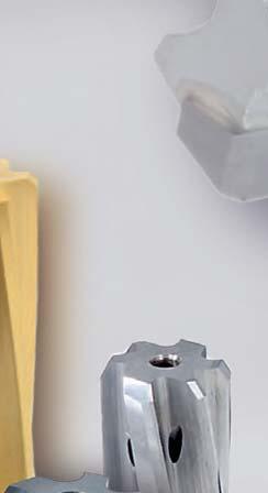
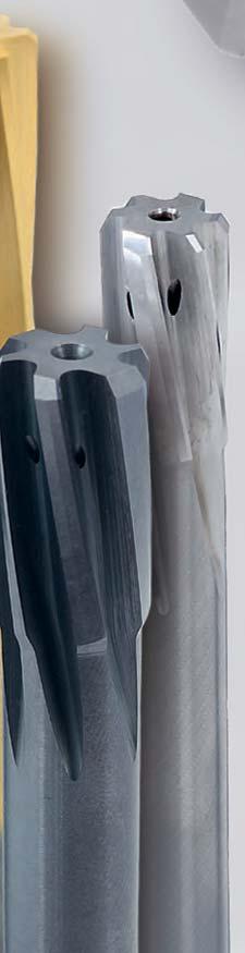
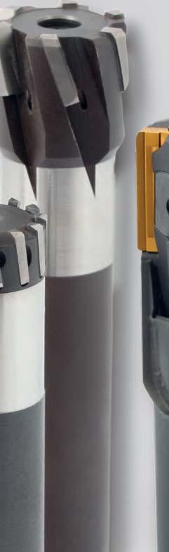
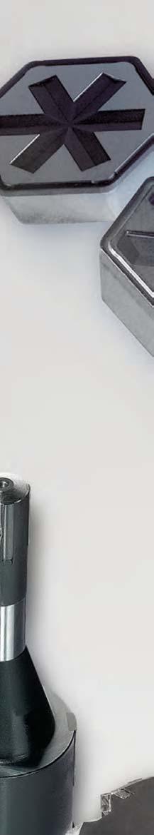
1 Reaming and Fine Boring MAPAL Competence Reaming and Fine Boring Tool with guide pads Fixed reamers


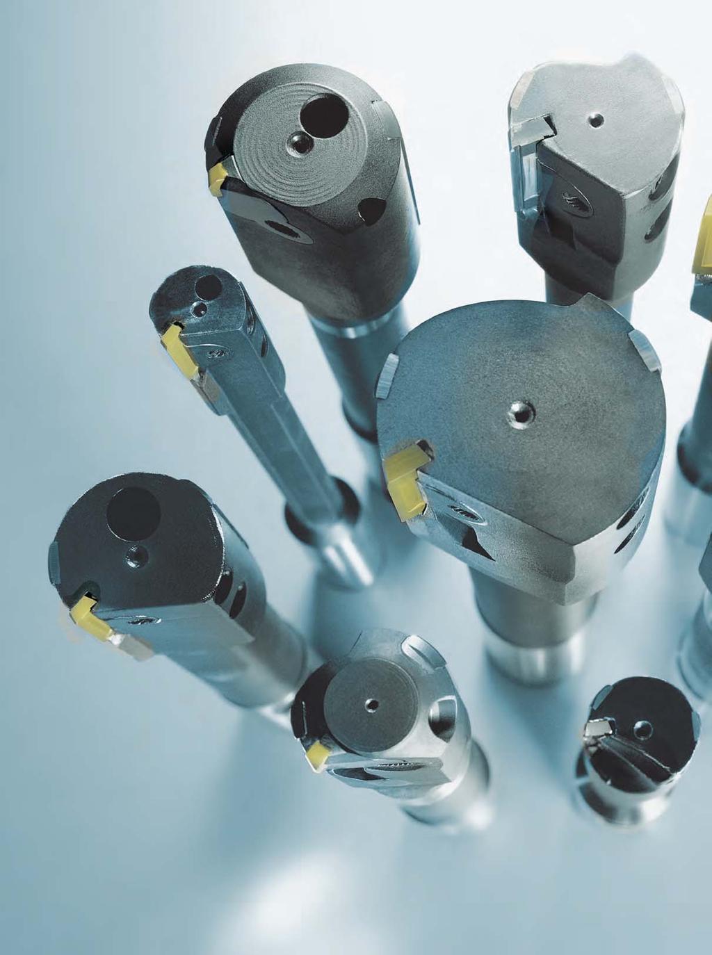
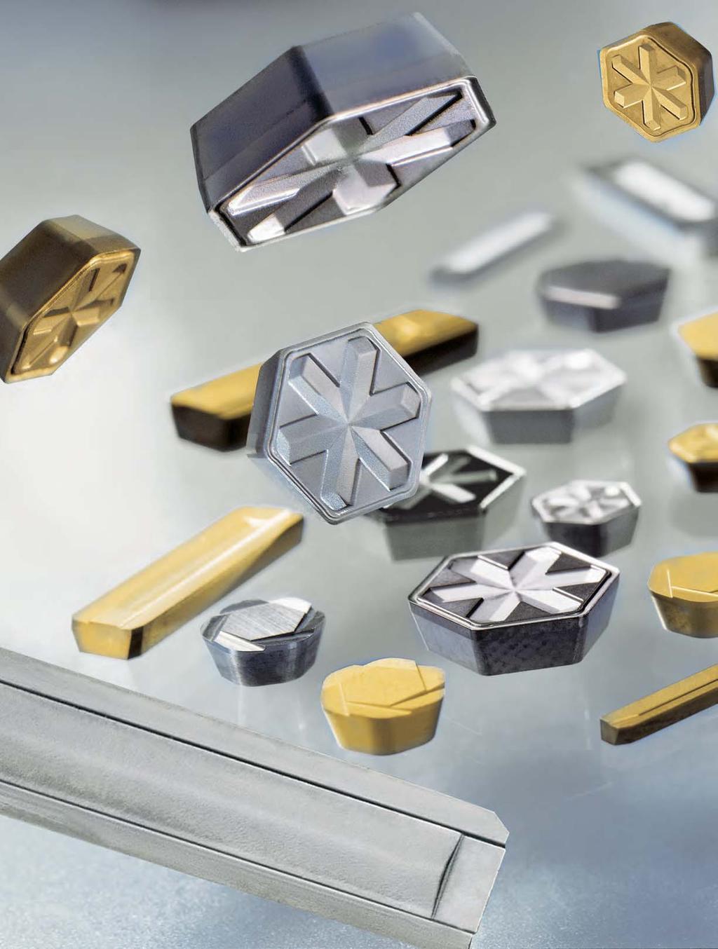
2 Competence Reaming and Fine Boring Today reaming and fine boring are the most widely used methods for precision machining bores. This produces highly economic machining results of the highest precision over the whole range of materials with reaming and fine boring tools with guide pads and with fixed multibladed reaming tools. From the wide range of single and twin-bladed reamers as well as fine boring tools with guide pads and WP or HX blades, through the HPR replaceable head reamers in combination with the high accuracy HFS clamping system right up to monoblock reamers made of carbide, cermet or HSS this catalogue gives you a complete overview of our know-how for the fine machining of bores. The MAPAL guide pad technology is unrivalled when it comes to the fine machining of bores in any material. The precision of the bore diameter, circularity and cylindrical form as well as the surface finish cannot be produced by other production means, or at least cannot be achieved cost-effectively. Starting from the range of standard series with proven cutting systems, MAPAL offer special tools adapted specifically to the particular production task in hand. Combination tools reliably produce complex part contours effectively and efficiently in one process step.


3 Reaming and Fine Boring Introduction Drastically reduced machining times are possible using fixed multi-bladed reamers. The multi-cutting edge allows higher feed values, which at the end of the day define the machining times. Due to specifically developed systems and the latest manufacturing technology, MAPAL also offers these tools with the highest accuracies. The product portfolio offers a wide variety that will satisfy all the requirements of the machining task. All areas are covered, from monoblock versions through to modern replaceable head systems. The standard products are complemented by special solutions which set new standards with respect to productivity. Solutions Fixed multi-bladed reamers Tools with Introduction guide pads Introduction 2 Tools with guide pads 4 Fixed multi-bladed reamers 6 System explanation Pictograms 10 Tools with guide pads 12 Article overview 14 Single-bladed reamers 16 Twin-bladed reamers 42 Indexable blades 54 EasyAdjust-System 60 High-performance reamers with cylindrical shank 68 Article overview 70 FixReam 74 MonoReam 96 MonoReam Plus 122 FeedPlus 132 Replaceable head reamers 144 HPR 144 CPR 188 Machine reamers 212 To DIN and similar to DIN 216 Solutions 288 Machining examples for Tools with guide pads EasyAdjust-System Fixed reamers and HPR Complete solutions 3


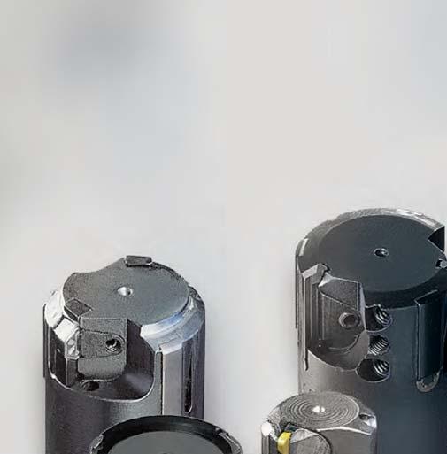
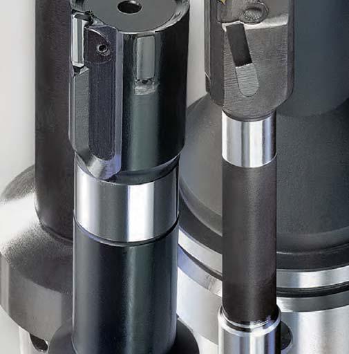
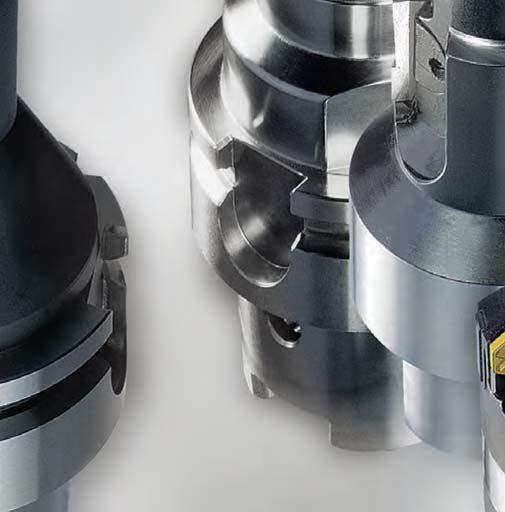
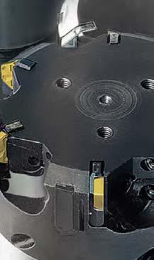
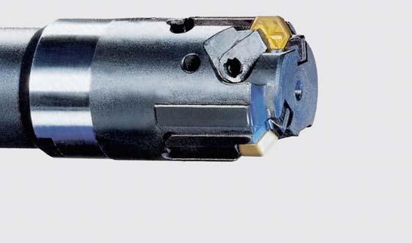
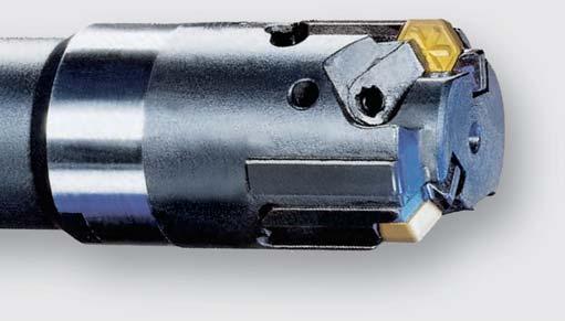
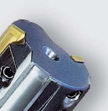
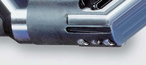
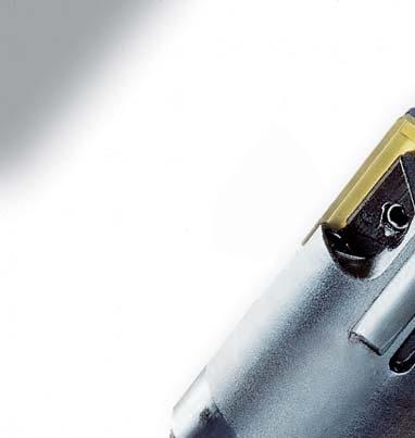
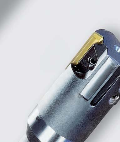
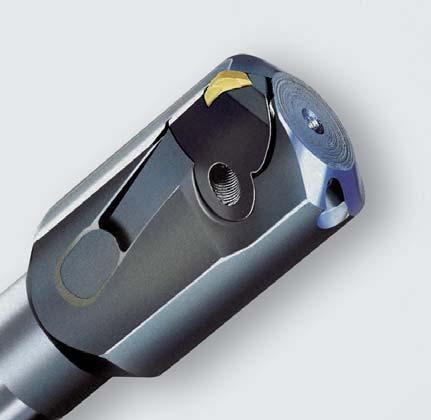
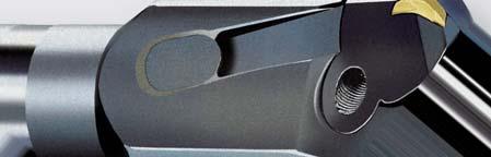
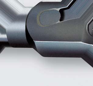
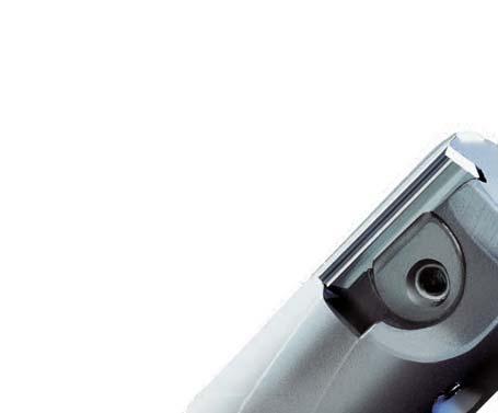
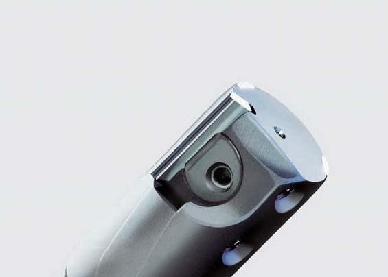
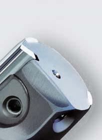
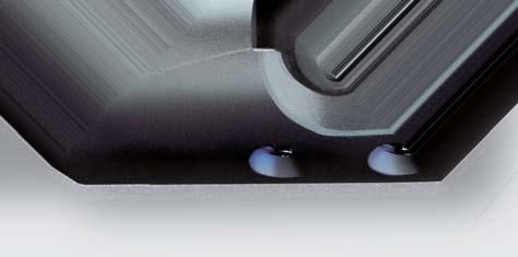
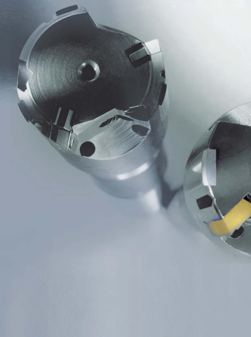
4 Tool with blades and guide pads. MAPAL tools with guide pads attribute their outstanding efficiency to direct guiding in the bore by guide pads and the high quality of MAPAL blades. In precision machining bores extraordinary demands are made on cutting materials, coatings, blade geometry and grinding quality. The continuous further development of the unmistakeable MAPAL principle forms the basis for the great success of these tools. Thanks to the use of the delicate adjusting system, the required diameters are produced to the μm from the first part. Competence in practice Single-bladed reamers Twin-bladed reamers Tools with guide pads are predominantly used in the production of large series. The use of a specifically modified special tool often then offers the most cost-effective solution. With the complete range of cutting systems available, the tool can be designed so that the optimum solution is found and the best results are achieved. Combinations of systems with modern cutting materials can also provide good solutions for complex applications. The MAPAL single-bladed reamers are designed to MAPAL s long-established principle. The cutting of the material and the guiding of the reamer in the bore is performed by the blades by means of precision grinding and guide pads located at the best geometric positions. The WP system is characterised by special cutting leads and exact adjustment in the diameter and also back tapering. With its hexagonal indexable blade, the HX cutting system offers six useful cutting edges. Optimum backlash-free mounting of the blades is guaranteed by the specially designed adjustment and clamping systems. Twin-bladed reamers allow the cutting speeds and feed rates to be increased compared with single-bladed reamers with guide pads. The blades are installed and adjusted so that they are staggered radially and axially. The splitting of the blades into leading and finish machining blades with a chipping thickness of just a few hundredth of a millimetre ensures very good surface finishes and long tool lives, even in materials that are difficult to machine. Based on this principle, MAPAL also offers multi-bladed adjustable tools with guide pads designed, for example, according to the 4+2 principle, i.e. with four leading blades and two finishing blades for even higher feed rates. 4


5 Reaming and Fine Boring Introduction Introduction Advantages: Exact adjustment of the machining diameter Optimum circularity and straightness of the bore thanks to the guide pad principle Cutting materials and coatings for every application Indexable blades with six cutting edges for maximum cost-effectiveness Blades and cutting materials External and taper reamers EasyAdjust-System In addition to the right selection and design of the tool s construction, the decision for the right cutting material is also of great significance to the quality and economic results of a cutting operation. Carbide, cermet, coatings, PCD and PcBN, the entire range of modern cutting materials is available from MAPAL for every workpiece material and for every machining task. The latest manufacturing technology employed in the production of the indexable blades today enables any chip former and chip breaker shape to be achieved even in super-hard cutting materials such as PcBN and PCD. External reamers allow outside diameters and shafts to be machined efficiently and with μm precision. The principle of the MAPAL external reamers is based on optimally absorbing and dispersing the cutting forces using guide pads so that no displacement forces and bending moments are exerted on the workpiece. Taper fits in machine engineering make very high demands on surface finish, lead accuracy and circularity deviations in order to ensure the crucial contact ratio of the fit. The MAPAL principle is also applied to taper reamers in order to process reliably the highest tolerances during machining. A drastic reduction in the setting time for tools with guide pad technology was the goal of the latest new development from MAPAL the EasyAdjust-System. The heart of the system is an innovative cassette that stably holds the blades with their six or four cutting edges without any play. The back taper of the minor cutting edge is already integrated into this cassette, thus eliminated the need for this adjustment. Due to the exact guidance of the cassette on a precision guide pin, the back taper remains unchanged even during diameter adjustments. 5


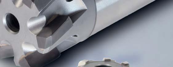
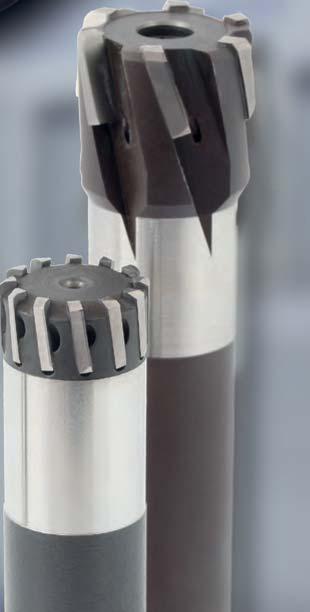
6 Fixed multi-bladed reamers more blades for more performance Drastically reduced machining times are possible using fixed multi-bladed reamers. The multi-cutting edge allows higher feed values, which at the end of the day define the machining times. Due to specifically developed systems and the latest manufacturing technology, MAPAL also offers these tools with the highest accuracies. The product portfolio offers a wide variety that will satisfy all the requirements of the machining task. All areas are covered, from monoblock versions through to modern replaceable head systems. The standard products are complemented by special solutions which set new standards with respect to productivity. Competence in practice Micro mini reamers High-performance reamers MAPAL as the major specialist for complete machining solutions naturally offers all its reamers also as special solutions tailored to the customer s requirements. The combination of stages, chamfers and plane surface machining makes these tools very cost-effective. Productive and non-productive times are shortened and productivity is significantly increased. MAPAL has developed a new range of micro reamers of solid carbide and HSS as well as reamers with extremely hard cutting materials such as PCD and PcBN specially for the machining of small parts. This product range includes VHM reamers from a diameter of 0.6 mm for the machining of steel, cast iron, aluminium, sintered aluminium or hardened materials. With the newly developed PcBN high-performance reamers, a specially developed process allows a PCD or PcBN layer to be applied to the face side of a body made of solid carbide. Reamers with diameters of under 3 mm, with six blades and cooling channels with only 0.3 mm diameter can thus be produced for the machining of difficult materials or for hard machining. The innovative and further developed monoblock tools allow practically any materials to be machined. Even difficult materials can be easily machined thanks to the modular principle with modified blades and coatings. MAPAL high-performance reamers with cylindrical shank are available with basically 2 different designs, either consisting of a basic body with separately attached blades of carbide, cermet, PcBN and PCD, or of monolithic design made from solid carbide with blades machined from the basic body material. 6


7 Reaming and Fine Boring Introduction Introduction Advantages: Maximum flexibility thanks to the wide range of different series Monoblock and replaceable head systems Diameter range from 0.6 to 400 mm Customised special solutions in all series With and without internal cooling Suitable for practically all materials Replaceable head reamers DIN reamers Regrinding service MAPAL offers replaceable head reamers with different head systems. The replaceable head systems impress with exact radial run-out and changeover accuracy, and with safe and simple handling, particularly during assembly and dismantling. The standard product spectrum includes a wide range of diameters, versions for through bores and blind holes as well as a broad choice of cutting materials. The HFS system is also characterised by the possibility of radial tool clamping. NC machine reamers are a particularly inexpensive variant for the production of precision bores. Although the performance data are below those of high-performance reamers of solid carbide and cermet, these tools are widely used since they are characterised in particular by their simple handling. Here again, MAPAL offers a broad range of tools which are mostly available from stock or which can be delivered in intermediate dimensions at short notice. In addition, MAPAL offers machine reamers similar to DIN with straight shank diameters for direct clamping in standard hydraulic and shrink chucks. With regrinding or repairs to ensure economical use of tools! To help you tap the full potential of your fixed multi-bladed reamers, MAPAL offers a regrinding and repair service for your used tools. Reamers can generally be reground several times after reaching the end of their tool life. Especially with high-quality tools such as high-performance reamers, the level of utilisation of any tool can be considerably improved by retipping or regrinding. This saves costs for new tools. To ensure consistently good machining results, however, the work must be performed by a professional. 7


8 Technology Engineering Products Worldwide TECHNOLOGY The specialist for minimum quantity lubrication and dry machining Minimum quantity lubrication (MQL) and dry machining are particularly important features for the energy efficiency of a machine tool. The reason is the high power consumption of the high pressure pumps required for the cooling lubricant. Often these devices make up % of the total energy required by the machine. By converting a cylinder head machining operation to MQL, it was possible, for example, to completely do without a pump that operates in the pressure range up to 50 bar and that has a motor power rating of 12 kw. Advantages: MQL or dry machining possible for all machining methods and in all materials Special quality controls for MQL tools Complete range of clamping tools available for single and two-channel MQL supplies Demonstration and sample machining in the MAPAL technology centre PRODUCTS The innovative tool designs from the MAPAL production line cover the whole area of precision machining. Pecision machining tools, such as reaming, fine boring tools, gun boring tools, special tools with ISO elements, generating slide tools, plus PCD gun boring tools and circular milling tools, cutter heads and milling tools with tangential blades, together with the whole programme for the high precision HSK clamping system from the standard tool to the specific solution MAPAL offers the perfect product for your machining task. Vorteile: Dies ist ein Blindtext und nicht erwer fsijfljsf flkjsfkjsf wofklwfmk slkfsjowmr sfk 8 8

9 Reaming and Fine Boring Introduction ENGINEERING Introduction From production planning to production optimisation, a variety of service modules are available under the title CTS Complete Tooling Services. Competent technical advice from the first enquiry to the production process in operation is seen by MAPAL as a natural duty. Experienced, specialist tool experts work out the best possible process for your part. Once the tools are delivered, MAPAL offers any support needed for commissioning and handling the tools. TET Tool Expert Team re.tooling TOS Tool Optimizing Services MAPAL WORLDWIDE The best product, the optimum tool and specific, rapid service are worth nothing if they are not offered or made constantly available where the customer actually needs them day today. It is for this reason that for many years MAPAL has observed the motto Wherever the customer is, you will find MAPAL. Following the principle of this company policy, more than 20 MAPAL affiliated manufacturing companies and service stations have been established worldwide and are available to customers in all the major industrial locations of the world, fully functional in daily operation with all MAPAL products and new customer services. Subsidiaries in 21 countries and representatives in 25 countries employees worldwide 9


10 System explanation Pictograms 10


11 Reaming and Fine Boring Introduction SYSTEMS HOLDERS/ADAPTORS COOLANTS Introduction 1 Single-bladed reamers Morse taper shank (MT) Internal coolant supply for blind hole Twin-bladed reamers Cylindrical shank with clamping surface Internal coolant supply for through hole, straight fluted DIN DIN reamer Cylindrical shank with NC clamping surface Internal coolant supply, for through hole, left-hand fluted sdin Reamer similar to DIN Cylindrical shank, smooth CONNECTIONS + 4 μm Grinding tolerance HSK-A CFS replaceable head connection BLADES HSK-C HFS HFS replaceable head connection WP blade Module HFS HFS replaceable head connection with radial clamping HX blade BORING For through holes For blind holes 11


12 12


13 Reaming and Fine Boring Tools with guide pads Tools with guide pads Tools with guide pads The MAPAL guide pad technology is unrivalled when it comes to the fine machining of bores in any material. The precision of the bore diameter, circularity and cylindrical form as well as the surface finish cannot be produced by other production means, or at least cannot be achieved cost-effectively. Starting from the range of standard series with proven cutting systems, MAPAL offers special tools adapted specifically to the particular production task in hand. Combination tools reliably produce complex part contours effectively and efficiently in one process step. Article overview 14 Single-bladed reamers 16 Twin-bladed reamers 42 Indexable blades 54 EasyAdjust-System 60 13


14 Single and twin-bladed reamers 1 WP single-bladed reamers HX single-bladed reamers WP twin-bladed reamers HX twin-bladed reamers 14
15 Reaming and Fine Boring Tools with guide pads Introduction Article overview single and twin-bladed reamers WP single-bladed reamers HX single-bladed reamers MN2000 MN2023 MN6023 Page 18 Page 28 Page 32 Morse taper shank External coolant supply MN2001 Cylindrical shank with NC clamping surface Internal coolant supply MN2024 MN6024 Page 20 Page 29 Page 33 Cylindrical shank with NC clamping surface Internal coolant supply Tools with guide pads Cylindrical shank with clamping surface External coolant supply Cylindrical shank with NC clamping surface Internal coolant supply Cylindrical shank with NC clamping surface Internal coolant supply MN2002 Page 22 Page 30 MN2043 Cylindrical shank with clamping surface External coolant supply Cylindrical shank with NC clamping surface Internal coolant supply MN2003 Page 24 MN2044 Page 31 Cylindrical shank with clamping surface Internal coolant supply Cylindrical shank with NC clamping surface Internal coolant supply MN2004 Page 26 Cylindrical shank with clamping surface Internal coolant supply WP twin-bladed reamers HX twin-bladed reamers MN2034 MN2223 MN6223 Page 27 Page 44 Page 45 Cylindrical shank with clamping surface Internal coolant supply Cylindrical shank with NC clamping surface Internal coolant supply MN2223 MN6223 Cylindrical shank with NC clamping surface Internal coolant supply 15
16 16

17 Reaming and Fine Boring Tools with guide pads Single-bladed reamers Single-bladed reamers A feature of the MAPAL WP single-bladed tools is the indexable blade with two cutting edges. The cutting leads required for reaming have a double cutting lead with a flat ground section. Because of the adjustable back taper for the blade, the effect of the secondary cutting edge can be aligned with the machining task in question. The application of the series illustrated in this brochure is carried outsubject to the machine, either on the floating holder or directly in a rigid holder. Standard tools are fitted with carbide guide pads. WP single-bladed reamers MN2000 Morse taper shank (MK) 18 MN2001 Cylindrical shank with clamping surface 20 MN2002 MN2003 Cylindrical shank with clamping surface 22 MN2004 MN2034 Cylindrical shank with clamping surface 26 MN2023 MN2024 Cylindrical shank with NC clamping surface MN2043 MN2044 Smooth cylindrical shank 30 HX single-bladed reamers 28 MN6023 MN6024 Cylindrical shank with NC clamping surface 32 Machining values for single-bladed reamers 34 Adjustment instructions for single-bladed reamers 38 Setting fixtures
18 Reaming and Fine Boring Tools with guide pads Single-bladed reamers WP single-bladed reamers MN A MK l 2 l 1 l 3 l 4 Clamping Adjusting Torx screw/ Clamping Adjusting screw Adjusting wedge Clamping screw plate MN 620 MN 619 Length Blade Order No. Order No. Order No. Order No. ø * l 1 l 2 l 3 l 4 MK A size (size) (size) (size) (size) 5,00-5,29 126** 62 60, (SP) (M1,6x3,9) (GR-1YN) (M2x1,8) (GR-06) 5,30-5,49 126** 62 60, (SP) (M1,6x4,4) (GR-1YN) (M2x2) (GR-06) 5,50-6,19 126** 62 60, (SP) (M2x4) (GR-1X) (M2x2) (GR-07) 6,20-6,90 126** 62 60, (SP) (M2x5) (GR-1X) (M2x2,5) (GR-07) 6,91-7,49 136** 62 70, (M2,5x4,8) (GR-1W) (M2,5x2,2) (GR-08) 7,50-7,79 136** 62 70, (M2,5x5,2) (GR-1W) (M2,5x2,5) (GR-09) 7,80-7, , (M3LH/RHx5) (GR-0F) (M3x2,5) (GR-0) 8,00-8, , (M3LH/RHx5) (GR-0F) (M3x2,5) (GR-0) 8,80-9, , (M3LH/RHx6) (GR-0N) (M3x3) (GR-0) 9,30-9, , (M3LH/RHx6) (GR-1N) (M3x3) (GR-0) 9,80-11, , (M3LH/RHx6) (GR-1N) (M3x3) (GR-1) 11,30-11, , (M4x0,5LH/RHx6,5) (GR-2F) (M4x3) (GR-2) 11,80-12, , (M4x0,5LH/RHx6,5) (GR-2F) (M4x3) (GR-2) 12,30-13, , (M4x0,5LH/RHx6,5) (GR-2F) (M4x4) (GR-2) 13,30-14, , (M4x0,5LH/RHx9) (GR-2N) (M4x5) (GR-2) 14,30-15, , (M4x0,5LH/RHx9) (GR-2N) (M4x5) (GR-2) 15,30-16, (M4x0,5LH/RHx9) (GR-2N) (M4x5) (GR-2) 16,30-18, (M4x0,5LH/RHx9) (GR-2N) (M4x5) (GR-2) Dimensions Clamping screw MN 618 Torx screw Accessories 18
19 Reaming and Fine Boring Tools with guide pads Single-bladed reamers WP single-bladed reamers MN 2000 Dimensions Clamping Accessories Adjusting Clamping screw Clamping Adjusting screw Adjusting wedge MN 618 plate MN 620 MN 619 Length Blade Order No. Order No. Order No. Order No. ø * l 1 l 2 l 3 l 4 MK A size (size) (size) (size) (size) Tools with guide pads 18,30-20, (M4x0,5LH/RHx9) (GR-2N) (M4x8) (GR-2) 20,30-22, (M4x0,5LH/RHx9) (GR-2N) (M4x8) (GR-2) 22,30-23, (M4x0,5LH/RHx9) (GR-2N) (M4x8) (GR-2) 23,30-26, (M4x0,5LH/RHx9) (GR-2N) (M4x8) (GR-2) 26,30-28, (M4x0,5LH/RHx9) (GR-2N) (M4x8) (GR-2) 28,30-29, (M4x0,5LH/RHx9) (GR-2N) (M4x8) (GR-2) 29,30-32, (M4x0,5LH/RHx9) (GR-2N) (M4x8) (GR-2) 32,30-35, , , (M4x0,5LH/RHx9) (GR-2N) (M4x8) (GR-2) 35,30-40, , , (M4x0,5LH/RHx9) (GR-2N) (M4x8) (GR-2) 40,30-48, , , (M4x0,5LH/RHx9) (GR-3N) (M6x15) (GR-4) 48,30-59, , , (M4x0,5LH/RHx9) (GR-3N) (M6x15) (GR-4) 59,80-79, , , (M4x0,5LH/RHx9) (GR-3N) (M6x15) (GR-4) 79, , , (M4x0,5LH/RHx9) (GR-3N) (M6x15) (GR-4) SP = blade cannot be turned. The appropriate floating holder can be found in our special catalogue»mapal Competence - Clamping«. See page 38 for setting notes and fitting of accessories. See page 53 for order example. *Values do not indicate adjustment range but the sizes for the various diameters (only adjustable within a tolerance field). **With 2,5 mm long center spigot for, less than 7,8 mm. When ordering, please state required guide pad grade (carbide, cermet or PCD). Unless stated, the guide pads will be supplied in carbide. See page 56 for selection of indexable blades. 19
20 Reaming and Fine Boring Tools with guide pads Single-bladed reamers WP single-bladed reamers MN d 2 l 2 l 1 l 3 l 4 K Clamping Adjusting Torx screw/ Clamping Adjusting screw Adjusting wedge Clamping screw plate MN 620 MN 619 Blade Order No. Order No. Order No. Order No. ø * ø d 2 h9 l 1 l 2 l 3 l 4 K h12 size (size) (size) (size) (size) 5,00-5, ** (SP) (M1,6x3,9) (GR-1YN) (M2x1,8) (GR-06) 5,30-5, ** (SP) (M1,6x4,4) (GR-1YN) (M2x2) (GR-06) 5,50-6, ** (SP) (M2x4) (GR-1X) (M2x2) (GR-07) 6,20-6, ** (SP) (M2x5) (GR-1X) (M2x2,5) (GR-07) 6,91-7, ** (M2,5x4,8) (GR-1W) (M2,5x2,2) (GR-08) 7,50-7, ** (M2,5x5,2) (1W) (M2,5x2,5) (GR-09) 7,80-7, (M3LH/RHx5) (GR-0F) (M3x2,5) (GR-0) 8,00-8, (M3LH/RHx5) (GR-0F) (M3x2,5) (GR-0) 8,30-8, (M3LH/RHx5) (GR-0F) (M3x3) (GR-0) 8,80-9, (M3LH/RHx6) (GR-0N) (M3x3) (GR-0) 9,30-9, (M3LH/RHx6) (GR-1N) (M3x3) (GR-0) 9,80-10, (M3LH/RHx6) (GR-1N) (M3x3) (GR-1) 10,30-11, (M3LH/RHx6) (GR-1N) (M3x3) (GR-1) 11,30-12, (M4x0,5LH/RHx6,5) (GR-2F) (M4x3) (GR-2) 12,30-13, (M4x0,5LH/RHx6,5) (GR-2F) (M4x4) (GR-2) 13,30-14, (M4x0,5LH/RHx9) (GR-2N) (M4x5) (GR-2) 14,30-15, (M4x0,5LH/RHx9) (GR-2N) (M4x5) (GR-2) 15,30-16, (M4x0,5LH/RHx9) (GR-2N) (M4x5) (GR-2) Dimensions Clamping screw MN 618 Torx screw Accessories 20
21 Reaming and Fine Boring Tools with guide pads Single-bladed reamers WP single-bladed reamers MN 2001 Dimensions Accessories Clamping Adjusting Clamping screw Clamping Adjusting screw Adjusting wedge MN 618 plate MN 620 MN 619 Blade Order No. Order No. Order No. Order No. ø * ø d 2 h9 l 1 l 2 l 3 l 4 K h12 size (size) (size) (size) (size) Tools with guide pads 16,30-17, (M4x0,5LH/RHx9) (GR-2N) (M4x5) (GR-2) 17,30-18, (M4x0,5LH/RHx9) (GR-2N) (M4x5) (GR-2) 18,30-19, (M4x0,5LH/RHx9) (GR-2N) (M4x8) (GR-2) 19,30-20, (M4x0,5LH/RHx9) (GR-2N) (M4x8) (GR-2) 20,30-21, , (M4x0,5LH/RHx9) (GR-2N) (M4x8) (GR-2) 21,30-22, , (M4x0,5LH/RHx9) (GR-2N) (M4x8) (GR-2) 22,30-23, , (M4x0,5LH/RHx9) (GR-2N) (M4x8) (GR-2) 23,30-24, (M4x0,5LH/RHx9) (GR-2N) (M4x8) (GR-2) 24,30-25, (M4x0,5LH/RHx9) (GR-2N) (M4x8) (GR-2) 25,30-26, (M4x0,5LH/RHx9) (GR-2N) (M4x8) (GR-2) 26,30-27, (M4x0,5LH/RHx9) (GR-2N) (M4x8) (GR-2) 27,30-29, (M4x0,5LH/RHx9) (GR-2N) (M4x8) (GR-2) 29,30-30, (M4x0,5LH/RHx9) (GR-2N) (M4x8) (GR-2) 30,30-32, (M4x0,5LH/RHx9) (GR-2N) (M4x8) (GR-2) SP = blade cannot be turned. The appropriate floating holder can be found in our special catalogue»mapal Competence - Clamping«. See page 38 for setting notes and fitting of accessories. See page 53 for order example. *Values do not indicate adjustment range but the sizes for the various diameters (only adjustable within a tolerance field). **With 2,5 mm long center spigot for, less than 7,8 mm. When ordering, please state required guide pad grade (carbide, cermet or PCD). Unless stated, the guide pads will be supplied in carbide. See page 56 for selection of indexable blades. 21
22 Reaming and Fine Boring Tools with guide pads Single-bladed reamers WP single-bladed reamers MN d 2 l 2 l 1 l 3 l 4 Clamping Adjusting Torx screw/ Clamping Adjusting screw Adjusting wedge Clamping screw plate MN 620 MN 619 Blade Order No. Order No. Order No. Order No. ø * ø d 2 h7 l 1 l 2 l 3 l 4 size (size) (size) (size) (size) 5,00-5, ** (SP) (M1,6x3,9) (GR-1YN) (M2x1,8) (GR-06) 5,30-5, ** (SP) (M1,6x4,4) (GR-1YN) (M2x2) (GR-06) 5,50-6, ** (SP) (M2x4) (GR-1X) (M2x2) (GR-07) 6,20-6, ** (SP) (M2x5) (GR-1X) (M2x2,5) (GR-07) 6,91-7, ** (M2,5x4,8) (GR-1W) (M2,5x2,2) (GR-08) 7,50-7, ** (M2,5x5,2) (GR-1W) (M2,5x2,5) (GR-09) 7,80-8, (M3LH/RHx5) (GR-0F) (M3x2,5) (GR-0) 8,30-8, (M3LH/RHx5) (GR-0F) (M3x3) (GR-0) 8,80-9, (M3LH/RHx6) (GR-0N) (M3x3) (GR-0) 9,30-9, (M3LH/RHx6) (GR-1N) (M3x3) (GR-0) 9,80-11, (M3LH/RHx6) (GR-1N) (M3x3) (GR-1) 11,30-11, (M4x0,5LH/RHx6,5) (GR-2F) (M4x3) (GR-2) 11,80-12, (M4x0,5LH/RHx6,5) (GR-2F) (M4x3) (GR-2) 12,30-13, (M4x0,5LH/RHx6,5) (GR-2F) (M4x4) (GR-2) Dimensions Clamping screw MN 618 Torx screw Accessories 22
23 Reaming and Fine Boring Tools with guide pads Single-bladed reamers WP single-bladed reamers MN 2002 Dimensions Clamping Accessories Adjusting Torx screw/ Clamping Adjusting screw Adjusting wedge Clamping screw plate MN 620 MN 619 Blade Order No. Order No. Order No. Order No. ø * ø d 2 h7 l 1 l 2 l 3 l 4 size (size) (size) (size) (size) Tools with guide pads 13,30-14, (M4x0,5LH/RHx9) (GR-2N) (M4x5) (GR-2) 14,30-18, (M4x0,5LH/RHx9) (GR-2N) (M4x5) (GR-2) 18,30-19, (M4x0,5LH/RHx9) (GR-2N) (M4x8) (GR-2) 19,80-20, (M4x0,5LH/RHx9) (GR-2N) (M4x8) (GR-2) 20,30-26, (M4x0,5LH/RHx9) (GR-2N) (M4x8) (GR-2) 26,30-40, (M4x0,5LH/RHx9) (GR-2N) (M4x8) (GR-2) 40,30-59, (M4x0,5LH/RHx9) (GR-3N) (M6x15) (GR-4) 59, (M4x0,5LH/RHx9) (GR-3N) (M6x15) (GR-4) SP = blade cannot be turned. The appropriate floating holder can be found in our special catalogue»mapal Competence - Clamping«. See page 38 for setting notes and fitting of accessories. See page 53 for order example. *Values do not indicate adjustment range but the sizes for the various diameters (only adjustable within a tolerance field). **With 2,5 mm long center spigot for, less than 7,8 mm. When ordering, please state required guide pad grade (carbide, cermet or PCD). Unless stated, the guide pads will be supplied in carbide. See page 56 for selection of indexable blades. 23
24 Reaming and Fine Boring Tools with guide pads Single-bladed reamers WP single-bladed reamers MN d 2 l 2 l 1 l 3 l 4 Dimensions Clamping Adjusting Torx screw/ Clamping Adjusting screw Adjusting wedge Clamping screw plate MN 620 MN 619 Blade Order No. Order No. Order No. Order No. ø * ø d 2 h7 l 1 l 2 l 3 l 4 size (size) (size) (size) (size) 5,00-5, ** (SP) (M1,6x3,9) (GR-1YN) (M2x1,8) (GR-06) 5,30-5, ** (SP) (M1,6x4,4) (GR-1YN) (M2x2) (GR-06) 5,50-6, ** (SP) (M2x4) (GR-1X) (M2x2) (GR-07) 6,20-6, ** (SP) (M2x5) (GR-1X) (M2x2,5) (GR-07) 6,91-7, ** (M2,5x4,8) (GR-1W) (M2,5x2,2) (GR-08) 7,50-7, ** (M2,5x5,2) (GR-1W) (M2,5x2,5) (GR-09) 7,80-8, (M3LH/RHx5) (GR-0F) (M3x2,5) (GR-0) 8,30-8, (M3LH/RHx5) (GR-0F) (M3x3) (GR-0) 8,80-9, (M3LH/RHx6) (GR-0N) (M3x3) (GR-0) 9,30-9, (M3LH/RHx6) (GR-1N) (M3x3) (GR-0) 9,80-11, (M3LH/RHx6) (GR-1N) (M3x3) (GR-1) 11,30-11, (M4x0,5LH/RHx6,5) (GR-2F) (M4x3) (GR-2) 11,80-12, (M4x0,5LH/RHx6,5) (GR-2F) (M4x3) (GR-2) 12,30-13, (M4x0,5LH/RHx6,5) (GR-2F) (M4x4) (GR-2) Clamping screw MN 618 Torx screw Accessories 24
25 Reaming and Fine Boring Tools with guide pads Single-bladed reamers WP single-bladed reamers MN 2003 Dimensions Accessories Clamping Adjusting Clamping screw Clamping Adjusting screw Adjusting wedge MN 618 plate MN 620 MN 619 Blade Order No. Order No. Order No. Order No. ø * ø d 2 h7 l 1 l 2 l 3 l 4 size (size) (size) (size) (size) Tools with guide pads 13,30-14, (M4x0,5LH/RHx9) (GR-2N) (M4x5) (GR-2) 14,30-18, (M4x0,5LH/RHx9) (GR-2N) (M4x5) (GR-2) 18,30-19, (M4x0,5LH/RHx9) (GR-2N) (M4x8) (GR-2) 19,80-20, (M4x0,5LH/RHx9) (GR-2N) (M4x8) (GR-2) 20,30-26, (M4x0,5LH/RHx9) (GR-2N) (M4x8) (GR-2) 26,30-40, (M4x0,5LH/RHx9) (GR-2N) (M4x8) (GR-2) 40,30-59, (M4x0,5LH/RHx9) (GR-3N) (M6x15) (GR-4) 59, (M4x0,5LH/RHx9) (GR-3N) (M6x15) (GR-4) SP = blade cannot be turned. The appropriate floating holder can be found in our special catalogue»mapal Competence - Clamping«. See page 38 for setting notes and fitting of accessories. See page 53 for order example. *Values do not indicate adjustment range but the sizes for the various diameters (only adjustable within a tolerance field). **With 2,5 mm long center spigot for, less than 7,8 mm. When ordering, please state required guide pad grade (carbide, cermet or PCD). Unless stated, the guide pads will be supplied in carbide. See page 56 for selection of indexable blades. 25
26 Reaming and Fine Boring Tools with guide pads Single-bladed reamers WP single-bladed reamers MN d 2 l 2 l 1 l 3 l 4 5,90-6, ** (SP) (M1,6x3,9) (GR-1YN) (M2x2) (GR-06) 6,30-6, ** (SP) (M1,6x4,4) (GR-1YN) (M2x2,5) (GR-06) 6,91-7, ** (SP) (M1,6x4,4) (GR-1YN) (M2x2,5) (GR-06) 7,30-7, ** (SP) (M2x5) (GR-1X) (M2x3) (GR-07) 7,80-8, ** (SP) (M2x5) (GR-1X) (M2x3) (GR-07) 8,30-9, (M2,5x5,2) (GR-1W) (M2,5x3) (GR-09) 9,80-10, (M2,5x5,2) (GR-1W) (M2,5x4) (GR-09) 10,30-11, (M3LH/RHx6) (GR-0N) (M3x3) (GR-1) 11,30-12, (M3LH/RHx6) (GR-0N) (M3x4) (GR-1) 12,30-14, (M3LH/RHx6) (GR-1N) (M3x4) (GR-1) 14,30-16, (M3LH/RHx6) (GR-1N) (M3x6) (GR-1) 16,30-17, (M4x0,5LH/RHx9) (GR-2N) (M4x5) (GR-2) 17,30-19, (M4x0,5LH/RHx9) (GR-2N) (M4x6) (GR-2) 19,80-26, (M4x0,5LH/RHx9) (GR-2N) (M4x8) (GR-2) 26,30-40, (M4x0,5LH/RHx9) (GR-2N) (M4x8) (GR-2) 40,30-59, (M4x0,5LH/RHx9) (GR-3N) (M6x15) (GR-4) 59, (M4x0,5LH/RHx9) (GR-3N) (M6x15) (GR-4) Dimensions Torx screw Clamping screw MN 618 Clamping Accessories Adjusting Torx screw Clamping Adjusting screw Adjusting wedge Clamping screw plate MN 620 MN 619 Blade Order No. Order No. Order No. Order No. ø * ø d 2 h7 l 1 l 2 l 3 l 4 size (size) (size) (size) (size) The appropriate floating holder can be found in our special catalogue»mapal Competence - Clamping«. See page 38 for setting notes and fitting of accessories. See page 53 for order example. *Values do not indicate adjustment range but the sizes for the various diameters (only adjustable within a tolerance field). **With 1 mm long center spigot for, less than 8,3 mm. When ordering, please state required guide pad grade (carbide, cermet or PCD). Unless stated, the guide pads will be supplied in carbide. See page 56 for selection of indexable blades. 26
27 Reaming and Fine Boring Tools with guide pads Single-bladed reamers WP single-bladed reamers MN d 2 l 2 l 1 l 3 l 4 Dimensions Accessories Clamping Adjusting Torx screw/ Clamping Adjusting screw Adjusting wedge Clamping screw plate MN 620 MN 619 Blade Order No. Order No. Order No. Order No. ø * ø d 2 h7 l 1 l 2 l 3 l 4 size (size) (size) (size) (size) Tools with guide pads 5,90-6, ** (SP) (M1,6x3,9) (GR-1YN) (M2x2) (GR-06) 6,30-7, ** (SP) (M1,6x4,4) (GR-1YN) (M2x2,5) (GR-06) 7,30-8, ** (SP) (M2x5) (GR-1X) (M2x3) (GR-07) 8,30-9, (M2,5x5,2) (GR-1W) (M2,5x3) (GR-09) 9,80-10, (M2,5x5,2) (GR-1W) (M2,5x4) (GR-09) 10,30-11, (M3LH/RHx6) (GR-0N) (M3x3) (GR-1) 11,30-12, (M3LH/RHx6) (GR-0N) (M3x4) (GR-1) 12,30-14, (M3LH/RHx6) (GR-1N) (M3x4) (GR-1) 14,30-16, (M3LH/RHx6) (GR-1N) (M3x6) (GR-1) 16,30-17, (M4x0,5LH/RHx9) (GR-2N) (M4x5) (GR-2) 17,30-19, (M4x0,5LH/RHx9) (GR-2N) (M4x6) (GR-2) 19,80-20, (M4x0,5LH/RHx9) (GR-2N) (M4x8) (GR-2) 20,30-26, (M4x0,5LH/RHx9) (GR-2N) (M4x8) (GR-2) 26,30-40, (M4x0,5LH/RHx9) (GR-2N) (M4x8) (GR-2) Clamping screw MN 618 Torx screw SP = blade cannot be turned. The appropriate floating holder can be found in our special catalogue»mapal Competence - Clamping«. See page 38 for setting notes and fitting of accessories. See page 53 for order example. *Values do not indicate adjustment range but the sizes for the various diameters (only adjustable within a tolerance field). **With 1 mm long center spigot for, less than 8,3 mm. When ordering, please state required guide pad grade (carbide, cermet or PCD). Unless stated, the guide pads will be supplied in carbide. See page 56 for selection of indexable blades. 27
28 Reaming and Fine Boring Tools with guide pads Single-bladed reamers WP single-bladed reamers MN 2023 NC version 1 d 2 l 2 l 1 l 3 l 4 Dimensions Accessories Clamping Adjusting Clamping screw Clamping Adjusting screw Adjusting wedge MN 618 plate MN 620 MN 619 Blade Order No. Order No. Order No. Order No. ø * ø d 2(-0,003) l 1 l 2 l 3 l 4 size (size) (size) (size) (size) 7,80-8, (M3LH/RHx5) (GR-0F) (M3x2,5) (GR-0) 8,30-8, (M3LH/RHx5) (GR-0F) (M3x3) (GR-0) 8,80-9, (M3LH/RHx5) (GR-0N) (M3x3) (GR-0) 9,30-11, (M3LH/RHx6) (GR-1N) (M3x3) (GR-1) 11,30-11, (M4x0,5LH/RHx6,5) (GR-2F) (M4x3) (GR-2) 11,80-12, (M4x0,5LH/RHx6,5) (GR-2F) (M4x3) (GR-2) 12,30-13, (M4x0,5LH/RHx6,5) (GR-2F) (M4x4) (GR-2) 13,30-14, (M4x0,5LH/RHx9) (GR-2N) (M4x5) (GR-2) 14,30-15, (M4x0,5LH/RHx9) (GR-2N) (M4x5) (GR-2) 15,80-17, (M4x0,5LH/RHx9) (GR-2N) (M4x5) (GR-2) 17,80-18, (M4x0,5LH/RHx9) (GR-2N) (M4x5) (GR-2) 18,30-19, (M4x0,5LH/RHx9) (GR-2N) (M4x6) (GR-2) 19,80-24, (M4x0,5LH/RHx9) (GR-2N) (M4x8) (GR-2) 24,80-28, (M4x0,5LH/RHx9) (GR-3N) (M6x10) (GR-4) 28,80-31, (M4x0,5LH/RHx9) (GR-3N) (M6x12) (GR-4) 31,80-37, (M4x0,5LH/RHx9) (GR-3N) (M6x15) (GR-4) 37,80-50, (M4x0,5LH/RHx9) (GR-3N) (M6x15) (GR-4) 50,30-80, (M4x0,5LH/RHx9) (GR-3N) (M6x15) (GR-4) See page 38 for setting notes and fitting of accessories. See page 53 for order example. *Values do not indicate adjustment range but the sizes for the various diameters (only adjustable within a tolerance field). When ordering, please state required guide pad grade (carbide, cermet or PCD). Unless stated, the guide pads will be supplied in carbide. See page 56 for selection of indexable blades. 28
29 Reaming and Fine Boring Tools with guide pads Single-bladed reamers WP single-bladed reamers MN 2024 NC version 1 d 2 l 2 l 1 l 3 l 4 Dimensions Accessories Clamping Adjusting Clamping screw Clamping Adjusting screw Adjusting wedge MN 618 plate MN 620 MN 619 Blade Order No. Order No. Order No. Order No. ø * ø d 2(-0,003) l 1 l 2 l 3 l 4 size (size) (size) (size) (size) Tools with guide pads 7,80-8, (M3LH/RHx5) (GR-0Z) (M3x2,5) (GR-0) 8,30-8, (M3LH/RHx5) (GR-0Z) (M3x3) (GR-0) 8,80-9, (M3LH/RHx5) (GR-0Z) (M3x3) (GR-0) 9,30-11, (M3LH/RHx6) (GR-0N) (M3x3) (GR-1) 11,30-11, (M3LH/RHx6) (GR-0N) (M3x4) (GR-1) 11,80-12, (M3LH/RHx6) (GR-0N) (M3x4) (GR-1) 12,30-14, (M3LH/RHx6) (GR-1N) (M3x4) (GR-1) 14,30-16, (M3LH/RHx6) (GR-1N) (M3x6) (GR-1) 16,30-17, (M4x0,5LH/RHx9) (GR-2N) (M4x5) (GR-2) 17,30-19, (M4x0,5LH/RHx9) (GR-2N) (M4x6) (GR-2) 19,80-24, (M4x0,5LH/RHx9) (GR-2N) (M4x8) (GR-2) 24,80-27, (M4x0,5LH/RHx9) (GR-3N) (M6x10) (GR-4) 27,80-28, (M4x0,5LH/RHx9) (GR-3N) (M6x10) (GR-4) 28,80-31, (M4x0,5LH/RHx9) (GR-3N) (M6x12) (GR-4) 31,80-37, (M4x0,5LH/RHx9) (GR-3N) (M6x15) (GR-4) 37,80-50, (M4x0,5LH/RHx9) (GR-3N) (M6x15) (GR-4) See page 38 for setting notes and fitting of accessories. See page 53 for order example. *Values do not indicate adjustment range but the sizes for the various diameters (only adjustable within a tolerance field). When ordering, please state required guide pad grade (carbide, cermet or PCD). Unless stated, the guide pads will be supplied in carbide. See page for selection of indexable blades. 29
30 Reaming and Fine Boring Tools with guide pads Single-bladed reamers WP single-bladed reamers MN 2043 NC version 1 d 2 l 2 l 1 l 3 l 4 Clamping screw Clamping Adjusting screw Adjusting wedge MN 618 plate MN 620 MN 619 Blade Order No. Order No. Order No. Order No. ø * ø d 2 h6 l 1 l 2 l 3 l 4 size (size) (size) (size) (size) 7,80-8, (M3LH/RHx5) (GR-0F) (M3x2,5) (GR-0) 8,30-8, (M3LH/RHx5) (GR-0F) (M3x3) (GR-0) 8,80-9, (M3LH/RHx5) (GR-0N) (M3x3) (GR-0) 9,30-11, (M3LH/RHx6) (GR-1N) (M3x3) (GR-1) 11,30-11, (M4x0,5LH/RHx6,5) (GR-2F) (M4x3) (GR-2) 11,80-12, (M4x0,5LH/RHx6,5) (GR-2F) (M4x3) (GR-2) 12,30-13, (M4x0,5LH/RHx6,5) (GR-2F) (M4x4) (GR-2) 13,30-14, (M4x0,5LH/RHx9) (GR-2N) (M4x5) (GR-2) 14,30-15, (M4x0,5LH/RHx9) (GR-2N) (M4x5) (GR-2) 15,80-17, (M4x0,5LH/RHx9) (GR-2N) (M4x5) (GR-2) 17,80-18, (M4x0,5LH/RHx9) (GR-2N) (M4x5) (GR-2) 18,30-19, (M4x0,5LH/RHx9) (GR-2N) (M4x6) (GR-2) 19,80-24, (M4x0,5LH/RHx9) (GR-2N) (M4x8) (GR-2) 24,80-28, (M4x0,5LH/RHx9) (GR-3N) (M6x10) (GR-4) 28,80-31, (M4x0,5LH/RHx9) (GR-3N) (M6x12) (GR-4) 31,80-37, (M4x0,5LH/RHx9) (GR-3N) (M6x15) (GR-4) 37,80-50, (M4x0,5LH/RHx9) (GR-3N) (M6x15) (GR-4) 50,30-80, (M4x0,5LH/RHx9) (GR-3N) (M6x15) (GR-4) Dimensions Clamping Accessories Adjusting See page 38 for setting notes and fitting of accessories. See page 53 for order example. *Values do not indicate adjustment range but the sizes for the various diameters (only adjustable within a tolerance field). When ordering, please state required guide pad grade (carbide, cermet or PCD). Unless stated, the guide pads will be supplied in carbide. See page 56 for selection of indexable blades. 30
31 Reaming and Fine Boring Tools with guide pads Single-bladed reamers WP single-bladed reamers MN 2044 NC version 1 d 2 l 2 l 1 l 3 l 4 Dimensions Accessories Clamping Adjusting Clamping screw Clamping Adjusting screw Adjusting wedge MN 618 plate MN 620 MN 619 Blade Order No. Order No. Order No. Order No. ø * ø d 2 h6 l 1 l 2 l 3 l 4 size (size) (size) (size) (size) Tools with guide pads 7,80-8, (M3LH/RHx5) (GR-0Z) (M3x2,5) (GR-0) 8,30-8, (M3LH/RHx5) (GR-0Z) (M3x3) (GR-0) 8,80-9, (M3LH/RHx5) (GR-0Z) (M3x3) (GR-0) 9,30-11, (M3LH/RHx6) (GR-0N) (M3x3) (GR-1) 11,30-11, (M3LH/RHx6) (GR-0N) (M3x4) (GR-1) 11,80-12, (M3LH/RHx6) (GR-0N) (M3x4) (GR-1) 12,30-14, (M3LH/RHx6) (GR-1N) (M3x4) (GR-1) 14,30-16, (M3LH/RHx6) (GR-1N) (M3x6) (GR-1) 16,30-17, (M4x0,5LH/RHx9) (GR-2N) (M4x5) (GR-2) 17,30-19, (M4x0,5LH/RHx9) (GR-2N) (M4x6) (GR-2) 19,80-24, (M4x0,5LH/RHx9) (GR-2N) (M4x8) (GR-2) 24,80-27, (M4x0,5LH/RHx9) (GR-3N) (M6x10) (GR-4) 27,80-28, (M4x0,5LH/RHx9) (GR-3N) (M6x10) (GR-4) 28,80-31, (M4x0,5LH/RHx9) (GR-3N) (M6x12) (GR-4) 31,80-37, (M4x0,5LH/RHx9) (GR-3N) (M6x15) (GR-4) 37,80-50, (M4x0,5LH/RHx9) (GR-3N) (M6x15) (GR-4) See page 38 for setting notes and fitting of accessories. See page 53 for order example. *Values do not indicate adjustment range but the sizes for the various diameters (only adjustable within a tolerance field). When ordering, please state required guide pad grade (carbide, cermet or PCD). Unless stated, the guide pads will be supplied in carbide. See page 56 for selection of indexable blades. 31
32 Reaming and Fine Boring Tools with guide pads Single-bladed reamers HX single-bladed reamers MN 6023 NC version 1 d 2 l 2 l 1 l 3 l 4 Dimensions Accessories Clamping Adjusting Clamping screw Clamping Adjusting screw Adjusting wedge MN 618 plate MN 620 MN 619 Blade Order No. Order No. Order No. Order No. ø * ø d 2(-0,003) l 1 l 2 l 3 l 4 size (size) (size) (size) (size) 13,83-14, ** (M4x0,5LH/RHx6,5) (PX25R) (M3x2,5) (GR-12) 14,50-14, ** (M4x0,5LH/RHx6,5) (PX25R) (M3x2,5) (GR-12) 14,83-16, ** (M4x0,5LH/RHx6,5) (PX25R) (M3x3) (GR-12) 16,50-16, ** (M4x0,5LH/RHx6,5) (PX25R) (M3x4) (GR-12) 16,83-17, ** (M4x0,5LH/RHx9) (PX25R) (M3x4) (GR-12) 17,83-19, ** (M4x0,5LH/RHx9) (PX25R) (M4x3) (GR-13) 19,83-21, ** (M4x0,5LH/RHx9) (PX26R) (M4x4) (GR-13) 21,83-24, ** (M4x0,5LH/RHx9) (PX26R) (M4x6) (GR-13) 24,83-37, (M4x0,5LH/RHx9) (PX26R) (M4x8) (GR-13) 37,83-50, (M4x0,5LH/RHx9) (PX26R) (M4x8) (GR-13) 50,17-80, (M4x0,5LH/RHx9) (PX26R) (M4x8) (GR-13) See page 39 for setting notes and fitting of accessories. See page 53 for order example. *Values do not indicate adjustment range but the sizes for the various diameters (only adjustable within a tolerance field). **With 1 mm long center spigot for d1, less than 22,50 mm. When ordering, please state required guide pad grade (carbide, cermet or PCD). Unless stated, the guide pads will be supplied in cermet. See page 58 for selection of indexable blades. 32
33 Reaming and Fine Boring Tools with guide pads Single-bladed reamers HX single-bladed reamers MN 6024 NC version 1 d 2 l 2 l 1 l 3 l 4 Dimensions Accessories Clamping Adjusting Clamping screw Clamping Adjusting screw Adjusting wedge MN 618 plate MN 620 MN 619 Blade Order No. Order No. Order No. Order No. ø * ø d 2(-0,003) l 1 l 2 l 3 l 4 size (size) (size) (size) (size) Tools with guide pads 14,83-16, ** (M4x0,5LH/RHx6,5) (PX25R) (M3x3) (GR-12) 16,50-16, ** (M4x0,5LH/RHx6,5) (PX25R) (M3x4) (GR-12) 16,83-17, ** (M4x0,5LH/RHx9) (PX25R) (M3x4) (GR-12) 17,83-19, ** (M4x0,5LH/RHx9) (PX25R) (M4x3) (GR-13) 19,83-21, ** (M4x0,5LH/RHx9) (PX26R) (M4x4) (GR-13) 21,83-24, ** (M4x0,5LH/RHx9) (PX26R) (M4x6) (GR-13) 24,83-37, (M4x0,5LH/RHx9) (PX26R) (M4x8) (GR-13) 37,83-50, (M4x0,5LH/RHx9) (PX26R) (M4x8) (GR-13) 50,17-80, (M4x0,5LH/RHx9) (PX26R) (M4x8) (GR-13) Guide pad quality: Cermet See page 39 for setting notes and fitting of accessories. See page 53 for order example. *Values do not indicate adjustment range but the sizes for the various diameters (only adjustable within a tolerance field). **With 1 mm long center spigot for, less than 22,50 mm. See page 58 for selection of indexable blades. 33
34 Reaming and Fine Boring Tools with guide pads Single-bladed reamers 1 Machining values for WP single-bladed reamers The machining values given are guidelines. The optimum data for the particular machining operation should be calculated from trials or during the operation. The standard grades of guide pads for MAPAL reamers are carbide or cermet. These require a sufficient film of lubricant. By using PCD guide pads the surface quality and life of the pads can be considerably improved. Minimal lubrication MAPAL reamers can be supplied on request in a special design for minimal lubrication. Coolant Any standard commercial emulsions with a 1: 9 mixture are suitable for use with MAPAL reamers. When using PCD guide pads, the proportion of emulsion can be reduced. The best tool life is achieved with emulsions which contain mineral oil. Guide line values for coolant pressure and quantity for reamers with internal coolant supply ø- Quantity Pressure range litre/min bar Material P Unalloyed steel: structural-, cast-, free cutting-, case hardened steel Unalloyed/low alloyed steel: structural-, cast-, heat treat.-, tool steel, case hardened steel Lead alloyed free cutting steel Unalloyed/low alloyed steel: temp. resisting structural-, heat treat-, nitride-, tool steel High alloyed steel: Tool steel Stainless steel Series with external coolant supply Cutting lead form AD + AS Cutting depth 0,05-0,25 mm Cutting lead form AD Cutting depth 0,05 0,25 mm Top Cutting speed for Top Cutting speed for Feed rake cutting material Feed rake cutting material R m f* f* N/mm 2 (mm/rev) HU615 HU612 HC416 HP426 CU140 CP140 (mm/rev) HU615 HU612 HC416 HP426 CU140 CP140 PU620 < 500 0,1-0, < 60 < 60 0,1-0, ,1-0, < 60 < 60 0,1-0, ,1-0, < 60 < 60 0,1-0, > 900 0,1-0, < 60 < 60 0,1-0, ,1-0, < 50 < 50 0,1-0, < 60 < 60 < 60 < 600 0,1-0, < 60 < 60 0,1-0, M Stainless steel > 600 0,1-0, < 60 < 60 0,1-0, Stainless/heat resisting steel > 750 0,1-0, < 60 < 60 0,1-0, Grey cast iron 0,2-0, ,1-0, Alloyed grey cast iron Nodular iron ferritic/pearlitic; Malleable iron: GGG40-GGG55, GTW35-GTW55, GTS35-GTS55 Nodular iron pearlitic; Malleable iron: GGG60-GGG80, GTW65, GTS65-GTS70 Alloyed nodular iron 0,1-0, ,1-0, K < 600 0,1-0, ,1-0, > 600 0,1-0, ,1-0, ,1-0, ,1-0, Copper alloy, brass, lead alloyed bronze with long chips Copper, copper alloy, alu-, manganese-, phosphorus bronze with short chips Alu wrought alloy, magnesium wrought alloy Alu-casting alloy Si-content < 10 %, magnesium alloy Alu-casting alloy Si-content > 10 %, magnesium alloy 0,1-0, < 60 0,1-0, N 0,1-0, < 60 0,1-0, ,1-0, < 60 Not recommende ,1-0, < 60 0,1-0, ,1-0, < 60 0,1-0, Subject to discussion > 200 Plastics Please enquire Please enquire Reinforced plastics Please enquire Please enquire S Special alloyed steel, sintered materials Titanium, titanium iron Please enquire Please enquire 0,08-0, < 40 0,08-0,2 < 30 < 30 < 40 34
35 Reaming and Fine Boring Tools with guide pads Single-bladed reamers Pre-machining The allowance for reaming should be selected so that the cutting depth for reaming is reater than the premachining depth. The most favourable value is a cutting depth of approx. 0,15 mm, i.e. with a 0,3 mm allowance in the diameter. Cutting lead form The double cutting lead WP-AD and WP-AS should preferably be used, which with roughing blade is 15 and Series with internal coolant supply Cutting lead form AS + EK Cutting depth AS 0,05 0,25 mm, EK 0,05 0,15 mm 30 finishing blade 3. For details on the cutting lead forms, see Page 57. Cutting materials MAPAL offers a broad-based selection of cutting materials so that the right cutting material can be used for every material. 1 Carbide 2 Coated carbide 3 Cermet 4 Coated cermet 5 PCD polycristalline diamond 6 PcBN polycristalline cubic boron nitride * For high cutting speeds and large cutting depth, select small feed rates ** Feed limited because of extremely short cutting lead length Cutting lead form AZ Cutting depth 0,05 0,4 mm Feed Top Cutting speed for Top Cutting speed for for AS for EK rake cutting material Feed rake cutting material 6 f* f** f* (mm/rev) (mm/rev) FU801 FU HU615 HU612 HC416 HP426 CU140 CP140 PU620 FU801 FU485 (mm/rev) HU615 HU612 HC416 CU140 PU620 FU801 FU485 Tools with guide pads 0,1-0,3 0,08-0, ,08-0,2 0,1-0,3 0,08-0, ,08-0,2 0,1-0,3 0,08-0, ,08-0,2 0,1-0,3 0,08-0, ,08-0,2 0,1-0,3 0,08-0, < 80 < 80 < 80 0,08-0,2 0,1-0,2 0,08-0, ,08-0,2 0,1-0,2 0,08-0, ,08-0,2 0,1-0,2 0,08-0, ,08-0,2 0,1-0,3 0,08-0, ,08-0, Subject to discussion for cast iron or hard machining ,1-0,3 0,08-0, ,08-0, Subject to discussion for cast iron or hard machining ,1-0,3 0,08-0, ,08-0, ,1-0,3 0,08-0, ,08-0, Subject to discussion for cast iron or hard machining ,1-0,3 0,08-0, ,08-0, ,1-0,25 0,08-0, ,08-0, ,1-0,3 0,08-0, ,08-0, ,08-0,2 0,08-0, ,08-0, ,1-0,3 0,08-0, ,08-0, ,08-0,3 0,08-0, ,08-0, Subject to discussion > 200 Subject to discussion > 200 Please enquire Please enquire Please enquire Please enquire Please enquire Please enquire 0,08-0,15 0,08-0,15 < 50 < 50 < 60 0,08-0,15 < 50 < 50 < 60 35
36 Reaming and Fine Boring Tools with guide pads Single-bladed reamers 1 Machining values for HX single-bladed reamers The machining values given are guidelines. The optimum data for the particular machining operation should be calculated from trials or during the operation. The standard grades of guide pads for MAPAL reamers are carbide or cermet. These require a sufficient film of lubricant. By using PCD guide pads the surface quality and life of the pads can be considerably improved. Minimal lubrication MAPAL reamers can be supplied on request in a special design for minimal lubrication. Coolant Any standard commercial emulsions with a 1: 9 mixture are suitable for use with MAPAL reamers. When using PCD guide pads, the proportion of emulsion can be reduced. The best tool life is achieved with emulsions which contain mineral oil. Guide line values for coolant pressure and quantity for reamers with internal coolant supply ø- Quantity Pressure range litre/min bar Material HX blades without clamping groove for series with internal Cutting lead form R 0,8 and R 1,5 / Cutting depth 0,05-0,25 mm Cutting speed for Top Feed rake cutting material R m f* N/mm 2 (mm/rev) HU612 HU612 HC416 HP426 CU140 CP140 P M Unalloyed steel: structural-, cast-, free cutting-, case hardened steel Unalloyed/low alloyed steel: structural-, cast-, heat treat.-, tool steel, case hardened steel Lead alloyed free cutting steel Unalloyed/low alloyed steel: temp. resisting structural-, heat treat-, nitride-, tool steel High alloyed steel: Tool steel Stainless steel Stainless steel Stainless/heat resisting steel < 500 0,1-0, ,1-0, ,1-0, > 900 0,1-0, ,1-0, < 60 < 60 < 60 < 600 0,08-0, > 600 0,08-0, > 750 0,08-0, Grey cast iron 0,1-0, K Alloyed grey cast iron Nodular iron ferritic/pearlitic; Malleable iron: GGG40-GGG55, GTW35-GTW55, GTS35-GTS55 Nodular iron pearlitic; Malleable iron: GGG60-GGG80, GTW65, GTS65-GTS70 Alloyed nodular iron 0,1-0, < 600 0,1-0, > 600 0,1-0, ,1-0, N Copper alloy, brass, lead alloyed bronze with long chips Copper, copper alloy, alu-, manganese-, phosphorus bronze with short chips Alu wrought alloy, magnesium wrought alloy Alu-casting alloy Si-content < 10 %, magnesium alloy Alu-casting alloy Si-content > 10 %, magnesium alloy Plastics 0,1-0, ,1-0, ,08-0, ,1-0, ,08-0, Please enquire Reinforced plastics Please enquire S Special alloyed steel, sintered materials Titanium, titanium iron Please enquire 0,08-0,15 < 30 < 30 < 40 36
37 Reaming and Fine Boring Tools with guide pads Single-bladed reamers Pre-machining The allowance for reaming should be selected so that the cutting depth for reaming is greater than the premachining depth. The most favourable value is a cutting depth of approx. 0,15 mm, i.e. with a 0,3 mm allowance in the diameter. Cutting lead form The HX blades can be supplied with radius cutting leads of R 0,8 and R 1,5 and for HX blades with clamping groove with radius R 0,8 only. coolant supply Cutting materials MAPAL offers a broad-based selection of cutting materials so that the right cutting material can be used for every material. When machining steel with HX reamers, we recommend the use of cermet or coated cermet. This will produce excellent surfaces at high cutting speeds. 1 Carbide 2 Coated carbide 3 Cermet 4 Coated cermet 5 PCD polycristalline diamond 6 PcBN polycristalline cubic boron nitride * For high cutting speeds and large cutting depth, select small feed rates *** 1 = for steel and long-chip materials 2 = for cast iron and short-chip materials HX blades with clamping groove for series with internal coolant supply Tools with guide pads Chip form geometry *** Cutting lead form R 0,8 / Cutting depth 0,05-0,25 mm Cutting speed for Cutting speed for cutting material Feed cutting material 5 6 f* PU620 FU801 FU485 (mm/rev) 2 1 HU612 HU612 HC416 HP426 CU140 CP140 PU620 FU801 FU485 0,1-0, ,1-0, ,1-0, ,1-0, ,1-0, < 80 < 80 < 80 0,08-0, ,08-0, ,08-0, ,1-0, Subject to discussion for cast iron or hard machining ,1-0, ,1-0, ,1-0, Subject to discussion for cast iron or hard machining ,1-0, Subject to discussion > 200 0,1-0, ,1-0, ,08-0, ,1-0, ,08-0, Subject to discussion > 200 Please enquire Please enquire Please enquire 0,08-0,15 < 50 < 50 < 60 37


. 3. Turn the blade or insert new blade.")


38 Reaming and Fine Boring Tools with guide pads Single-bladed reamers Setting instructions for WP single-bladed reamers: Clamping screw WP blade Clamping plate Adjusting wedge Adjusting screw Accessories Indexable blade Torx screw/ Clamping screw MN 618 Clamping plate Adjusting screw MN 620 Adjusting wedge MN off 1 off 1 off 2 off 2 off Changing and setting the blade A B C D Turn torx screw or clamping screw (as shown). The clamping plate will be loosened. 1. Remove blade. 2. Clean the blade and blade seat (do not use compressed air note the adjusting wedge). 3. Turn the blade or insert new blade. and adjusting wedge. 2. Turn torx screw or clamping (as shown). The clamping plate will be tightened. E For rough adjustment, turn the front again 1/4 turn. F 1. For measurement and precision setting we recommend a precision micrometer. 2. Set the front and rear setting dimension for varying intervals with the G To make handling easier and ensure reliable setting, we recommend the use of a MAPAL setting device H With the setting mandrel (must be ordered separately) calibrate the MASTERSET. Setting mandrel has the minimum dimension for the bore. I Set the front and rear setting dimension for varying intervals with the Detailed setting notes can be found in the equipment s operating instructions. Note: For setting with the fixed bridge method, see WP twin-bladed reamers, Page 50. J K MAPAL UNISET: For easy setting of reamers MAPAL supplies electronic setting devices in vertical and for our special brochure on Setting devices. 38


.")
.")
. The clamping plate will be tightened.")


39 Reaming and Fine Boring Tools with guide pads Single-bladed reamers Setting instructions for HX single-bladed reamers: HX blade Clamping screw Clamping plate Adjusting wedge Accessories Indexable blade Changing and setting the blade Clamping screw MN 618 Clamping plate Adjusting screw MN 620 Adjusting screw Adjusting wedge MN off 1 off 1 off 1 off 1 off Tools with guide pads A B C D Turn the adjusting screw 1/2 turn be used to open (as shown). The clamping plate will be loosened. 1. Remove blade. 2. Clean blade and blade seat (do not use compressed air note the adjusting wedge). 3. Turn the blade 60 or insert new blade in cartridge. to be used to open (as shown). The clamping plate will be tightened. E For rough adjustment, turn again 1/4 turn. F 1. For measurement and precision setting we recommend a precision micrometer. 2. Set the required setting dimensions by turning To make handling easier and ensure reliable setting, we recommend the use of a MAPAL setting device. G With the setting mandrel (must be Set the required setting ordered separately) calibrate the dimensions by turning the MASTERSET. Setting mandrel has the minimum dimension for the bore. H I MAPAL UNISET: For easy setting of reamers MAPAL supplies electronic setting devices in vertical and horizontal designs. Detailed setting notes can be found in the equipment s operating instructions. Note: For setting with the fixed bridge method, see WP twin-bladed reamers, Page


 calibrate the MASTERSET.")

40 Reaming and Fine Boring Tools with guide pads Single-bladed reamers Setting instructions for HX single-bladed reamers Size 2 and size 3: Clamping screw HX blade Cartridge Adjusting wedge Accessories Clamping plate Adjusting screw Indexable blade Cartridge Clamping screw MN 618 Clamping plate Adjusting screw MN 620 Adjusting wedge MN off 1 off 1 off 1 off 2 off 2 off Changing and setting the blade A B C D adjusting screw 1/2 turn - to be used to open (as shown). The clamping plate and cartridge will be loosened. 1. Remove blade and cartridge. 2. Clean blade, cartridge and blade seat (do not use compressed air note the adjusting wedge). 3. Turn the blade 60 or insert new blade in cartridge. 4. Replace cartridge 1. Press blade and cartridge against to be used to open (as shown). The clamping plate will be tightened. E For rough adjustment, turn the front again 1/4 turn. To make handling easier and ensure reliable setting, we recommend the use of a MAPAL setting device F G H With the setting mandrel (must be ordered separately) calibrate the MASTERSET. Setting mandrel has the minimum dimension for the bore. Set the front and rear setting dimension for varying intervals with the rear approx. 0,005 to 0,010 mm. Detailed setting notes can be found in the equipment s operating instructions. Note: For setting with the fixed bridge method, see WP twin-bladed reamers, Page 50. MAPAL UNISET: For easy setting of reamers MAPAL supplies electronic special brochure on Setting devices. 40


41 Reaming and Fine Boring Tools with guide pads Single-bladed reamers Setting devices Setting with maximum precision! setting devices in its programme. From a mechanical to a electronic system with tool management, these setting devices offer the optimum solution for precision tool setting. MAPAL MASTERSET This mechanical setting device is designed for setting standard and simple special tools. Because of its modular construction, the basic device can be extended with numerous optional units. With a few simple hand movements, the MAPAL MASTERSET is converted into a vertical unit using the vertical stand. The advantages of this are the ability to hold heavy and long tools and hold tools directly in the HSK system. Tools with guide pads MAPAL MASTERSET MAPAL UNISET-H MAPAL UNISET The setting devices from the MAPAL UNISET series are distinguished by significant advantages with regard to universal use. In addition to precision tools for machining bores, milling tools can also be adjusted and measured. Through the use of the mechanical contact measuring technique, high dimensional accuracy is achieved. The contacted pressure is so low due to the special configuration that sensitive cutting materials such as PCD and PcBN can be set μm-exact without the danger of damaging the cutting edge. MAPAL UNISET-H The MAPAL UNISET-H is the horizontal version of the UNISET setting devices. In the basic version, with a 600 or 900 mm centre width, these setting devices guarantee high precision and reliable setting for the precision tools. The measurement results for the axes can be recorded with a printer. MAPAL UNISET-V standard The vertical versions, UNISET-V standard, is extremely robust in relation to external interference effects. In addition, all mechanical components are designed high-precision bearing for the spindle and the matched 3 μm is guaranteed for a projection length of 300 mm. function and a highly modern camera with CNC cont roller and operating software. The desired setting is thus MAPAL UNISET-V 41
42 42

43 Reaming and Fine Boring Tools with guide pads Twin-bladed reamers Tools with guide pads Twin-bladed reamers Both blades are ground to the highest precision, both are clamped and can be sensitively adjusted. However, the blades are not arranged in the same positions but offset radially and axially to one another. This means that the follow-on blade only machines to a very small chip thickness. This allows micro cutting, which ensures excellent surface finishes and outstanding tool life. When machining cast iron and steel materials in particular these tools often produce better results than the single-bladed reamers. WP twin-bladed reamers MN 2223 Cylindrical shank with NC clamping surface 44 HX twin-bladed reamers MN 6223 Cylindrical shank with NC clamping surface 45 Machining values for twin-bladed reamers 46 Adjustment instructions for twin-bladed reamers 50 Screwdriver for single and twin-bladed reamers
44 Reaming and Fine Boring Tools with guide pads Twin-bladed reamers WP twin-bladed reamers MN 2223 NC version d 2 l 2 l 1 l 3 l 4 ** Dimensions Clamping Adjusting Torx screw/ Clamping Adjusting screw Adjusting wedge Clamping screw plate MN 620 MN 619 Blade Order No. Order No. Order No. Order No. ø * ø d 2(-0,003) l 1 l 2 l 3 size (size) (size) (size) (size) 14,30-15, (M2,5x5,2) (GR-1W) (M2,5x3) (GR-33) 15,30-16, (M2,5x5,2) (GR-1W) (M2,5x4) (GR-33) 16,30-18, (M3LH/RHx6) (GR-0V) (M2,5x4) (GR-33) 18,30-19, (M3LH/RHx6) (GR-1V) (M3x3) (GR-31) 19,30-20, (M3LH/RHx6) (GR-1V) (M3x4) (GR-31) 20,30-22, (M3LH/RHx6) (GR-2KV) (M3x4) (GR-31) 22,30-24, (M3LH/RHx6) (GR-2KV) (M3x6) (GR-31) 24,30-26, (M4x0,5LH/RHx9) (GR-2V) (M4x5) (GR-34) 26,30-28, (M4x0,5LH/RHx9) (GR-2V) (M4x6) (GR-34) 28,30-29, (M4x0,5LH/RHx9) (GR-2V) (M4x8) (GR-34) 29,30-32, (M4x0,5LH/RHx9) (GR-3V) (M4x6) (GR-32) 32,30-37, (M4x0,5LH/RHx9) (GR-3V) (M4x8) (GR-32) 37,80-40, (M4x0,5LH/RHx9) (GR-3V) (M4x8) (GR-32) Torx screw Clamping screw MN 618 Accessoires Adjustment instructions and installation of the accessories, see page 50. Ordering example, see page 53. *Values indicate the sizes for different diameters (adjustable only within a tolerance field), not the adjustment range. **Pad length l 4 generally 15 mm. Please indicate the desired guide pad quality (HM, cermet or PCD) when ordering. Unless otherwise indicated, the guide pads will be delivered in cermet quality. Selection of indexable blades, see page
45 Reaming and Fine Boring Tools with guide pads Twin-bladed reamers HX twin-bladed reamers MN 6223 NC version d 2 X View X: S1 l 2 l 4 *** l 1 l 3 S2 Dimensions Reibahle Zubehörteile Accessoires zum Reibahlenkopf Clamping Adjusting Clamping screw Clamping Adjusting screw Adj. wedge Cartridge MN 618 plate MN 620 MN 619 Blade Order No. Order No. Order No. Order No. Order No. ø * ø d 2(-0,003) l 1 l 2 l 3 size (size) (size) (size) (size) (size) Tools with guide pads 21,83-25,82 20** (KX24R) (M3LH/RHx6) (SX22R) (M3x3) (GR-35/S2) (GR-37/S1) 25,83-29,82 20** (KX26R) (M3LH/RHx6) (SX24R) (M3x4) (GR-35) 29,83-31,82 20** (KX26R) (M4x0,5LH/RHx9) (SX26R) (M3x6) (GR-35) 31,83-37,82 20** (KX26R) (M4x0,5LH/RHx9) (SX25R) (M3x6) (GR-35) 37,83-39, (KX35R) (M4x0,5LH/RHx9) (SX35R) (M4x5) (GR-36) 39,83-42, (KX35R) (M4x0,5LH/RHx9) (SX35R) (M4x6) (GR-36) 42,83-47, (KX35R) (M4x0,5LH/RHx9) (SX35R) (M4x8) (GR-36) Adjustment instructions and installation of the accessories, see page 50. Ordering example, see page 53. *Values indicate the sizes for different diameters (adjustable only within a tolerance field), not the adjustment range. **With 1.5 mm long centring pin for < mm. ***Pad length l 4 generally 15 mm. Please indicate the desired guide pad quality (HM, cermet or PCD) when ordering. Unless otherwise indicated, the guide pads will be delivered in cermet quality. Selection of indexable blades, see page
46 Reaming and Fine Boring Tools with guide pads Twin-bladed reamers Machining values for WP twin-bladed reamers The machining values given are guidelines. The optimum data for the particular machining operation should be calculated from trials or during the operation. Various factors are decisive in calculating the values exactly: rigidity of the whole system: machine, tool and holder rigidity of the component part and workpiece clamping, especially at high feed rates the quality specifications for the finished workpiece the type of guide pads: carbide, cermet or PCD. Under optimum conditions, feed rates of up to 1,0 mm can be achieved in steel and grey cast iron. In principle lower feed rates produce a better surface finish, while higher feed rates reduce any vibrations which may occur. By varying the cutting speed, the surface can be improved by an increase, while a reduction produces a positive effect on chip form and wear. A change in the chip fracturing can be produced by a variation in the cutting depth. The allowance for reaming should be selected so that the cutting depth in the reaming operation is greater than the rough depth for the pre-machining operation. The most favourable value is a cutting depth of approximately 0,15 mm, in other words 0,3 mm allowance in the diameter. Material P Unalloyed steel: structural-, cast-, free cutting-, case hardened steel Unalloyed/low alloyed steel: structural-, cast-, heat treat.-, tool steel, case hardened steel Lead alloyed free cutting steel Unalloyed/low alloyed steel: temp. resisting structural-, heat treat-, nitride-, tool steel High alloyed steel: Tool steel Stainless steel Series with external coolant supply Cutting lead form AD + AS Cutting depth 0,05-0,25 mm Cutting lead form AD Cutting depth 0,05 0,25 mm Top Cutting speed for Top Cutting speed for R m Feed rake cutting material Feed rake cutting material f* f* N/mm 2 (mm/rev) HU615 HU612 HC416 HP426 CU140 CP140 (mm/rev) HU615 HU612 HC416 HP426 CU140 CU134 CP140 CP132 PU620 < 500 0,2-0, < 60 < 60 0,2-0, ,2-0, < 60 < 60 0,2-0, ,2-0, < 60 < 60 0,2-0, > 900 0,2-0, < 60 < 60 0,2-0, ,2-0, < 50 < 50 0,2-0, < 60 < 60 < 60 < 600 0,2-0, < 60 < 60 0,2-0, M Stainless steel > 600 0,2-0, < 60 < 60 0,2-0, Stainless/heat resisting steel > 750 0,2-0, < 60 < 60 0,2-0, Grey cast iron 0,3-0, ,3-0, Alloyed grey cast iron 0,25-0, ,25-0, K Nodular iron ferritic/pearlitic; Malleable iron: GGG40-GGG55, GTW35-GTW55, GTS35-GTS55 Nodular iron pearlitic; Malleable iron: GGG60-GGG80, GTW65, GTS65-GTS70 < 600 0,25-0, ,25-0, > 600 0,25-0, ,25-0, Alloyed nodular iron 0,25-0, ,25-0, Copper alloy, brass, lead alloyed bronze with long chips 0,2-0, < 60 0,2-0, N Copper, copper alloy, alu-, manganese-, phosphorus bronze with short chips Alu wrought alloy, magnesium wrought alloy Alu-casting alloy Si-content < 10 %, magnesium alloy Alu-casting alloy Si-content > 10 %, magnesium alloy 0,15-0, < 60 0,15-0, ,2-0, < 60 Not recommende ,25-0, < 60 0,25-0, ,25-0, < 60 0,25-0, Subject to discussion > 200 Plastics Please enquire Please enquire Reinforced plastics Please enquire Please enquire S Special alloyed steel, sintered materials Titanium, titanium iron Please enquire Please enquire 0,15-0, < 40 0,15-0,4 < 30 < 30 < 40 46
47 Reaming and Fine Boring Tools with guide pads Twin-bladed reamers Central supply of lubricant through the tool is advisable in every case. The use of minimal lubrication should only be applied with PCD guide pads. When using the MN 2225 and MN 2227 versions, attention should be particularly paid to good concentricity on the tool head. A value of < 5 μm is recommended. Cutting lead form The double cutting lead WP-AD and WP-AS should preferably be used, which with roughing blade are 15 and 30 and Series with internal coolant supply Cutting lead form AS + EK Cutting depth AS 0,05 0,25 mm, EK 0,05 0,15 mm the finishing blade 3. For details on the cutting lead forms, see Page 57. Cutting materials MAPAL offers a broad-based selection of cutting materials so that the right cutting material can be used for every material. 1 Carbide 2 Coated carbide 3 Cermet 4 Coated cermet 5 PCD polycristalline diamond 6 PcBN polycristalline cubic boron nitride Alternative radial rake for special cases * For high cutting speeds and large cutting depth, select small feed rates ** Feed limited because of extremely short cutting lead length Cutting lead form AZ Cutting depth 0,05 0,4 mm Feed Top Cutting speed for Top Cutting speed for for AS for EK rake cutting material Feed rake cutting material 6 f* f** f* FU801 FU485 (mm/rev) (mm/rev) HU615 HU612 HC416 HP426 CU140 CU134 CP140 PU620 FU801 FU485 (mm/rev) HU615 HU612 HC416 CU140 PU620 FU801 CP132 CU134 FU485 Tools with guide pads 0,2-0,6 0,15-0, ,15-0,4 0,2-0,6 0,15-0, ,15-0,4 0,2-0,6 0,15-0, ,15-0,4 0,2-0,6 0,15-0, ,15-0,4 0,2-0,45 0,15-0, < 80 < 80 < 80 0,15-0,4 0,2-0,6 0,15-0, ,15-0,4 0,2-0,6 0,15-0, ,15-0,4 0,2-0,6 0,15-0, ,15-0,4 0,3-0,75 0,15-0, ,15-0, Subject to discussion for cast iron or hard machining ,25-0,6 0,15-0, ,15-0, Subject to discussion for cast iron or hard machining ,25-0,6 0,15-0, ,15-0, ,25-0,6 0,15-0, ,15-0, Subject to discussion for cast iron or hard machining ,25-0,6 0,15-0, ,15-0, ,2-0,5 0,15-0, ,15-0, ,15-0,6 0,15-0, ,15-0, ,2-0,5 0,15-0, ,15-0, ,25-0,6 0,15-0, ,15-0, ,25-0,6 0,15-0, ,15-0, Subject to discussion > 200 Subject to discussion > 200 Please enquire Please enquire Please enquire Please enquire Please enquire Please enquire 0,15-0,4 0,15-0,4 < 50 < 50 < 60 0,15-0,4 < 50 < 50 < 60 47
48 Reaming and Fine Boring Tools with guide pads Twin-bladed reamers Machining values for HX twin-bladed reamers The machining values given are guidelines. The optimum data for the particular machining operation should be calculated from trials or during the operation. Various factors are decisive in calculating the values exactly: rigidity of the whole system: machine, tool and holder rigidity of the component part and workpiece clamping, especially at high feed rates the quality specifications for the finished workpiece the type of guide pads: Carbide, cermet or PCD. Under optimum conditions, feed rates of up to 1,0 mm can be achieved in steel and grey cast iron. In principle lower feed rates produce a better surface finish, while higher feed rates reduce any vibrations which may occur. By varying the cutting speed, the surface can be improved by an increase, while a reduction produces a positive effect on chip form and wear. A change in the chip fracturing can be produced by a variation in the cutting depth. The allowance for reaming should be selected so that the cutting depth in the reaming operation is greater than the rough depth for the pre-machining operation. The most favourable value is a cutting depth of approximately 0,15 mm, Material HX blades without clamping groove for series with internal Cutting lead form R 0,8 and R 1,5 / Cutting depth 0,05-0,25 mm Cutting speed for Top Feed rake cutting material R m f* N/mm 2 (mm/rev) HU612 HU612 HC416 HP426 CU140 CP140 P M Unalloyed steel: structural-, cast-, free cutting-, case hardened steel Unalloyed/low alloyed steel: structural-, cast-, heat treat.-, tool steel, case hardened steel Lead alloyed free cutting steel Unalloyed/low alloyed steel: temp. resisting structural-, heat treat-, nitride-, tool steel High alloyed steel: Tool steel Stainless steel Stainless steel Stainless/heat resisting steel < 500 0,2-0, ,2-0, ,2-0, > 900 0,2-0, ,2-0, < 60 < 60 < 60 < 600 0,2-0, > 600 0,2-0, > 750 0,2-0, Grey cast iron 0,3-0, K Alloyed grey cast iron Nodular iron ferritic/pearlitic; Malleable iron: GGG40-GGG55, GTW35-GTW55, GTS35-GTS55 Nodular iron pearlitic; Malleable iron: GGG60-GGG80, GTW65, GTS65-GTS70 Alloyed nodular iron 0,25-0, < 600 0,25-0, > 600 0,25-0, ,25-0, N Copper alloy, brass, lead alloyed bronze with long chips Copper, copper alloy, alu-, manganese-, phosphorus bronze with short chips Alu wrought alloy, magnesium wrought alloy Alu-casting alloy Si-content < 10 %, magnesium alloy Alu-casting alloy Si-content > 10 %, magnesium alloy Plastics 0,2-0, ,15-0, ,2-0, ,25-0, ,25-0, Please enquire Reinforced plastics Please enquire S Special alloyed steel, sintered materials Titanium, titanium iron Please enquire 0,15-0,4 < 30 < 30 < 40 48
49 Reaming and Fine Boring Tools with guide pads Twin-bladed reamers in other words 0,3 mm allowance in the diameter. Central supply of lubricant through the tool is advisable in every case. The use of minimal lubrication should only be applied with PCD guide pads. Cutting lead form The HX blades can be supplied with radius cutting leads of R 0,8 and R 1,5. coolant supply Cutting materials MAPAL offers a broad-based selection of cutting materials so that the right cutting material can be used for every material. When machining steel with HX reamers, it is advisable to use cermet and coated cermet. This will produce excellent surfaces at high cutting speeds. 1 Carbide 2 Coated carbide 3 Cermet 4 Coated cermet 5 PCD polycristalline diamond 6 PcBN polycristalline cubic boron nitride Alternative radial rake for special cases * For high cutting speeds and large cutting depth, select small feed rates *** 1 = for steel and long-chip materials 2 = for cast iron and short-chip materials HX blades with clamping groove for series with internal coolant supply Tools with guide pads Chip form geometry *** Cutting lead form R 0,8 / Cutting depth 0,05-0,25 mm Cutting speed for Cutting speed for cutting material Feed cutting material 5 6 f* PU620 FU801 FU485 (mm/rev) 2 1 HU612 HU612 HC416 HP426 CU140 CP140 PU620 FU801 FU485 0,2-0, ,2-0, ,2-0, ,2-0, ,2-0, < 80 < 80 < 80 0,2-0, ,2-0, ,2-0, ,3-0, Subject to discussion for cast iron or hard machining ,25-0, ,25-0, ,25-0, Subject to discussion for cast iron or hard machining ,25-0, Subject to discussion > 200 0,2-0, ,15-0, ,2-0, ,25-0, ,25-0, Subject to discussion > 200 Please enquire Please enquire Please enquire 0,15-0,4 < 50 < 50 < 60 49

.")
. 3. Turn the blade or insert new blade. 1.")
. The clamping plate will be tightened.")


50 Reaming and Fine Boring Tools with guide pads Twin-bladed reamers Setting instructions for WP twin-bladed reamers: Clamping screw WP blade Clamping plate Adjusting wedge Adjusting screw Accessoires Indexable blade Torx screw/ Clamping screw MN 618 Clamping plate Adjusting screw MN 620 Adjusting wedge MN off 2 off 2 off 4 off 4 off Changing and setting the blade A Turn the front and back adjusting screw 1/2 turn anti-clockwise. B C D Turn torx screw or clamping screw anti-clockwise from the top and clockwise from the bottom. Two keys need to be used to open (as shown). The clamping plate will be loosened. Note: The same procedure (Fig. A-E) also applies for the second blade. 1. Remove blade. 2. Clean the blade and blade seat (do not use compressed air note the adjusting wedge). 3. Turn the blade or insert new blade. 1. Press blade against back stop and adjusting wedge. 2. Turn torx screw or clamping screw clockwise from the top and anti-clockwise from the bottom. Two keys need to be used to open (as shown). The clamping plate will be tightened. E For rough adjustment, turn the front and back adjusting screw clockwise again 1/4 turn. To make handling easier and ensure reliable setting, we recommend the use of a MAPAL setting device. Blade μm Guide pad HMF as drg μm F G H I 1. MAPAL MASTERSET: Set the spacing for the MASTERSET to the blade length. 2. Zero the dial indicator on the guide pad following the blade. Blade 2 Setting Blade 1: Set the front and rear setting dimension for varying intervals with the adjusting screw. Setting dimension: amount of the blade over the following guide pad as in setting instructions Fig. H. Back tapering to rear approx. 0,01 to 0,015 mm. Setting Blade 2: Set the front and rear setting dimension for varying intervals with the adjusting screw. Setting dimension: amount of the blade below the following guide pad as in setting instructions Fig. H. Back tapering to rear approx. 0,01 to 0,015 mm. MAPAL UNISET: For easy setting of reamers MAPAL supplies electronic setting devices in vertical and horizontal designs. Please ask for our special brochure on Setting devices. Detailed setting notes can be found in the equipment s operating instructions. 50

. The clamping plate and cartridge will be loosened. Note: The same procedure (Fig. A-E) also applies for the second blade. 1.")


51 Reaming and Fine Boring Tools with guide pads Twin-bladed reamers Setting instructions for HX twin-bladed reamers: HX blade Cartridge Clamping screw Adjusting wedge Accessoires Indexable blade Cartridge Torx screw/ Clamping screw MN 618 Changing and setting the blade Clamping plate Clamping plate Adjusting screw MN 620 Adjusting screw Adjusting wedge MN off 2 off 2 off 2 off 4 off 4 off Tools with guide pads A B C D Turn the front and back adjusting screw 1/2 turn anti-clockwise. Turn clamping screw anticlockwise from the top and clockwise from the bottom. Two keys need to be used to open (as shown). The clamping plate and cartridge will be loosened. Note: The same procedure (Fig. A-E) also applies for the second blade. 1. Remove blade and cartridge. 2. Clean blade, cartridge and blade seat (do not use compressed air note the adjusting wedge). 3. Turn the blade 60 or insert new blade in cartridge. 4. Replace cartridge. 1. Press blade and cartridge against back stop and adjusting wedge. 2. Turn clamping screw clockwise from the top and anti-clockwise from the bottom. Two keys need to be used to open (as shown). E For rough adjustment, turn the front and back adjusting screw clockwise again 1/4 turn. To make handling easier and ensure reliable setting, we recommend the use of a MAPAL setting device. Blade μm Guide pad HMF as drg μm F G H I 1. MAPAL MASTERSET: Set the spacing for the MASTERSET to the blade length. 2. Zero the dial indicator on the guide pad following the blade. Blade 2 Setting Blade 1: Set the front and rear setting dimension for varying intervals with the adjusting screw. Setting dimension: amount of the blade over the following guide pad as in setting instructions Fig. H. Back tapering to rear approx. 0,005 to 0,010 mm. Setting Blade 2: Set the front and rear setting dimension for varying intervals with the adjusting screw. Setting dimension: amount of the blade below the following guide pad as in setting instructions Fig. H. Back tapering to rear approx. 0,005 to 0,010 mm. MAPAL UNISET: For easy setting of reamers MAPAL supplies electronic setting devices in vertical and horizontal designs. Please ask for our special brochure on Setting devices. Detailed setting notes can be found in the equipment s operating instructions. 51
52 Reaming and Fine Boring Tools with guide pads Twin-bladed reamers Screwdrivers/Keys for single- and twin-bladed reamers Screwdriver for screw spindle MN 618 Hexagonal key Screw spindle Key width MN 618 sw 1,5 sw 2,0 M3LH/RHx5 M3LH/RHx6 M4x0,5LH/RHx6,5 M4x0,5LH/RHx9 Screwdriver for Torx screw M1,6x3,9 M1,6x4,4 M2x4 M2x5 M2,5x4,8 M2,5x5,2 Torx screwdriver Size Torx screw TX 5 TX 6 TX 7 Note: The screwdrivers/keys are included in the supply when ordering reamers. Screwdriver for threaded pin MN 620 Adjusting screw Hexagonal key/key width MN 620 sw 0,9 sw 1,3 sw 2,0 sw 3,0 M2x1,8 M2x2 M2x2,5 M2x3 M2,5x2,2 M2,5x2,5 M2,5x3 M2,5x4 M3x2,5 M3x3 M3x4 M3x6 M4x3 M4x4 M4x5 M4x6 M4x8 M6x10 M6x12 M6x15 52
53 Reaming and Fine Boring Tools with guide pads Twin-bladed reamers Order example for WP and HX reamers Please provide the following details when ordering: Example 1 Order details for WP reamers Name Guide pad Production Tolerance Cutting lead grade ø code IT or dimensions (see page 57 for selection) Note: If you are unable to provide details of cutting lead code and top rake, please state type of material to be machined. Please state required guide pad grade (carbide, cermet or PCD). MN2002 Carbide 12 H 6 AD Example 2 Order details for HX reamers Name Guide pad Production Tolerance Cutting lead grade ø code IT or dimensions (see page 59 for selection) MN6023 PCD 38 +0, ,007 Tools with guide pads Order example for WP and HX indexable blades Example 1 Order details for WP blade: AS92R-O-HU615 Please provide the following details when ordering: Cutting Blade size Cutting direction Top rake Cutting material lead form (see page 57 (see page 57 (see page 57 (see page 57 for selection) for selection) for selection) for selection) AS 92 R 0 HU615 Example 2 Order details for HX blade: HX25RS3-CU140 Blade form Blade size Cutting lead Cutting direction Cutting edge Top rake Cutting material (see page 59 for selection) (see page 59 for selection) (see page 59 for selection) (see page 59 for selection) (see page 58 for selection) HX 2 5 R S 3 CU140 53
54 54

55 Reaming and Fine Boring Tools with guide pads Indexable blades Tools with guide pads Indexable blades the basis for successful tools Indexable blades WP blades 56 HX blades 58 Carbide, cermet, coatings, PCD and PcBN the whole range of modern cutting materials is available at MAPAL for every workpiece material and for every cutting task. The latest production technology for manufacturing blades today allows any chipformer and chipbreaker solution to be produced even with super hard materials such as PCD and PcBN. To ensure the MAPAL blades are safely held, a clamping groove is used which, when combined with the clamping plate and the adjustment elements, forms a highly positive system. This stability is an important requisite for long tool life and prevents the blades shifting. 55


56 Reaming and Fine Boring Tools with guide pads Indexable blades Blades for WP single-bladed and WP twin-bladed reamers End of life Roughness without F chamfer with F chamfer Stabilisation End of life The MAPAL principle improved by additional guiding on the blade Comparison of surface roughness for blades without and with F chamfer High speed clamping groove Even with high speed machining, the sintered clamping groove guarantees stable clamping by providing a positive connection between clamping plate and blade. This means the requirement is satisfied for meeting bore tolerances within a few microns and not only for high speed machining. The MAPAL F chamfer The F chamfer is the name given by MAPAL to an additional stabilising and guide chamfer on the blade. This chamfer can be applied to all newly manufactured MAPAL indexable blades in any designs and with any cutting leads. The surface quality is improved by the F chamfer because of the controlled wear and is consistent right to the end of the blade life. Blades with F chamfer make a greater contribution to guiding the tool, which is extremely important, particularly where with high speed machining or unfavourable length and diameter situations. A further advantage of the F chamfer lies in the higher dimensional stability and clearly longer blade life. The normally strong loss in dimension at the start of the cutting process is avoided and is slower and more constant over the whole of the blade life. The key to success The blades are coded using the following system: Cutting direction R = R.H. cutting L = L.H. cutting Cutting lead form AD = 3 /15 length 3 mm AS = 3 /30 length 1,3 mm EK = 3 /30 length 0,6 mm AZ = 3 /75 length 1,3 mm Radial rake O = 0 6 = 6 2 = 12 AS 92 R F 2 HU615 Size Select the size to suit the type of reamer. For allocation see product tables. 56 Only used for versions with F chamfer. Cutting material grade e.g. HU615 = carbide For other cutting material grades, see table on page 57.
57 Reaming and Fine Boring Tools with guide pads Indexable blades Cutting leads for WP blades ,25 Cutting lead AD Universal cutting lead for high quality surface finishes also for low cutting speeds; note cutting lead length of 3 mm; not suitable for aluminium. Max. cutting depth: 0,25 mm Radial rake: 0, 6, 12 1, ,25 Cutting lead AS (also end cutting available) Cutting lead suitable for all materials, high quality surface finish also for high cutting speeds; cutting lead length 1,3 mm. Max. cutting depth: 0,25 mm Radial rake: 0, 6, 12 0, ,15 Cutting lead EK (end cutting) Only use where a low cutting length of 0,6 mm is required; for all materials; do not exceed max. feed of 0,2 mm/rev. Max. cutting depth: 0,15 mm Radial rake: 0, 6, 12 Tools with guide pads 1, ,0 Cutting lead AZ For high cutting speeds; especially suitable for machining aluminium. Max. cutting depth: 1 mm Radial rake: 0, 6, 12 Other cutting leads available on request Cutting materials for WP blades Application area Material Group Properties Cutting material code Coating Code to ISO513 HU615 HW-K10 Wear resistance Strength P M K N S H Steel Stainless steel Grey cast iron Non-ferrous metals (Alu etc.) High heat resistant Hard Materials Uncoated carbide grade with wide range of applications; for general cutting tasks; suitable for use with low to medium utting speeds. HC416 CVD HC-K10 Coated carbide grade; better wear resistance than grade HU615, for use with medium to upper cutting speed range. HP426 PVD HC-P10 Coated carbide grade with minimum wear compared to HU615 grade; for use in upper to medium cutting speed range. CU140 - HT-P25 Uncoated cermet grade; note minimum speed; better surface finish because of high cutting speeds. Not with sintered clamping groove. CU134 - HT-P20 Uncoated cermet grade; note minimum speed; better surface finish because of high cutting speeds. CP132 PVD HC-P10 Coated cermet grade, better wear resistance than CU134; increase in cutting speed; note minimum speed. CP140 PVD HC-P10 Coated cermet grade, better wear resistance than CU140; increase in cutting speed; note minimum speed. Not with sintered clamping groove. PU620 - DP-K05 PCD grade for machining non-ferrous metals. FU801 - BN-K05 PcBN grade for machining hardened steel. FU485 - BN-K05 PcBN grade for machining cast iron, also with heavily interrupted cut. Cutting material code: HU615 = carbide; HC416, HP426 = coated carbide; CU140, CU134 = cermet; CP140/CP134 = coated cermet; PU620 = PCD-polycristalline diamond; FU801, FU485 = PcBN-polycristalline cubic boron nitride Application area Main application Further application 57


58 Reaming and Fine Boring Tools with guide pads Indexable blades Blades for HX single-bladed and HX twin-bladed reamers Six precision-ground cutting edges for maximum economy in precision machining bores. 2. Better blade clamping with clamping grooves for a stable positioning, even for difficult cuts and high spindle speeds. 3. Chip breakers for controlled chip flow and achieving the required chip form. 4. The guide chamfer on the periphery of the blade in conjunction with the adjustable back taper ensures maximum tool life. The force and positive connection of the blades guarantees they are safely held. Held in finely adjustable cartridges. The close allocation of the roughing and finishing blade produces the best possible surface quality with the twin-bladed tool in conjunction with the sensitive adjustment facility. The MAPAL HX system, which takes its name from the hexagonal form of the blades with 6 precision-ground cutting edges, sets the benchmark in economic terms for precision machining bores. Both with single-bladed and the multi-bladed reamers, the system has clear advantages because of the six-fold use of the HX blades: The HX blades with clamping groove are in special cartridges and can be adjusted with two adjusting wedges. They therefore produce the best results with regard to surface finish. The clamping plate grips directly into the clamping grooves on the blade, guaranteeing that the blade is held absolutely securely in the cartridges, even under difficult application conditions with extremely large allowances. Cutting materials for HX blades Application area Material group Properties Cutting material code Coating Code to ISO 513 HU612 HW-K10 Wear resistance Strength P M K N S H Steel Stainless steel Grey cast iron Non-ferrous metals (Alu etc.) High heat resistant Hard Materials Uncoated carbide grade with wide range of applications; for general cutting tasks; suitable for use with low to medium cutting speeds. HC416 CVD HC-K10 Coated carbide grade; better wear resistance than grade HU612, for use with medium to upper cutting speed range. HP426 PVD HC-P10 Coated carbide grade with minimum wear compared to HU612 grade; for use in upper to medium cutting speed range. CU140 - HT-P25 Uncoated cermet grade; note minimum speed; better surface finish because of high cutting speeds. Not with sintered clamping groove. CU134 - HT-P20 Uncoated cermet grade; note minimum speed; better surface finish because of high cutting speeds. CP140 PVD HC-P10 Coated cermet grade, better wear resistance than CU134; increase in cutting speed; note minimum speed. CP132 PVD HC-P10 Coated cermet grade, better wear resistance than CU140; increase in cutting speed; note minimum speed. Not with sintered clamping groove. PU620 - DP-K05 PCD grade for machining non-ferrous metals. FU801 - BN-K05 PcBN grade for machining hardened steel. FU485 - BN-K05 PcBN grade for machining cast iron, also with heavily interrupted cut. Cutting material code: HU612 = carbide; HC416, HP426 = coated carbide; CU140/CU134 = cermet; CP140/CP132 = coated cermet; PU620 = PCD-polycristalline diamond; FU801, FU485 = PcBN-polycristalline cubic boron nitride 58 Application area Main application Further application
59 Reaming and Fine Boring Tools with guide pads Indexable blades HX blades without clamping grooves The blades are coded using the following system: 6 cutting edges Hexagonal Cutting direction R = R.H. cutting L = L.H. cutting RL = R.H. and L.H. cutting Radial rake 0 = 0 3 = 3 6 = 6 Blade size 2 = inscribed circle ø 6 mm 3 = inscribed circle ø 10 mm HX 2 5 R S 3 CU140 Cutting material quality e.g.: CU140 = cermet For further cutting material grades see table on page 58. Tools with guide pads Cutting lead 5 = R 1,5 8 = R 0,8 Cutting edge S = sharp V = rounded F = negative chamfering only in conjunction with PcBN HX blades with clamping grooves The blades are coded using the following system: Cutting lead 8 = R 0,8 6 cutting edges Hexagonal HX RL CU134 Chip form geometry 1 = for steel and long chip materials 2 = for cast iron and short chip materials Cutting material quality e.g.: CU134 = cermet For further cutting material grades see table on page 58. Blade size 2 = inscribed circle ø 6 mm 3 = inscribed circle ø 10 mm Cutting direction RL = R.H. and L.H. cutting 59
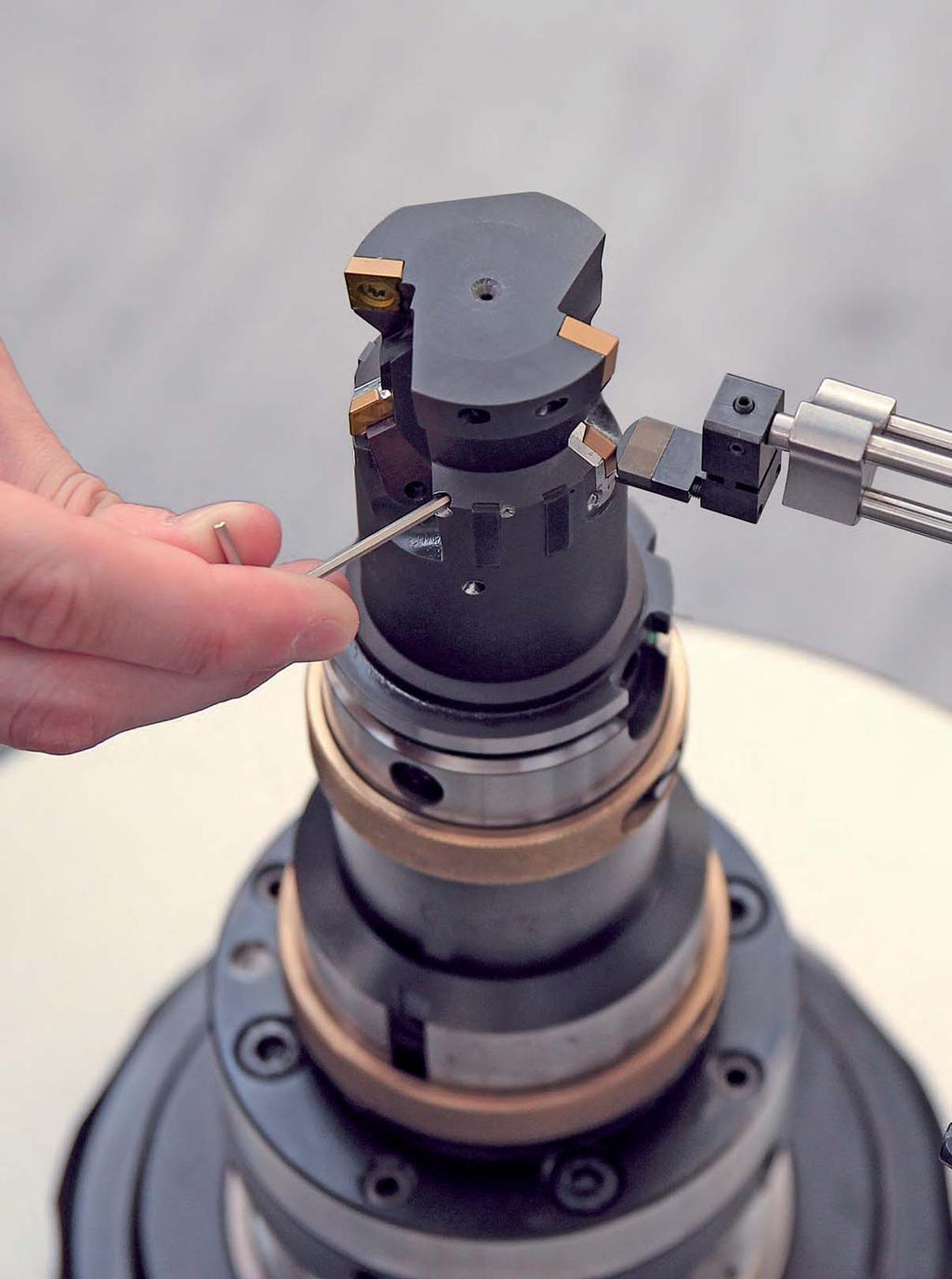
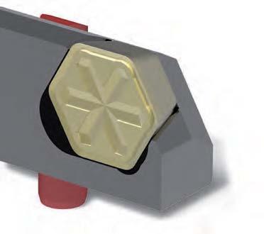
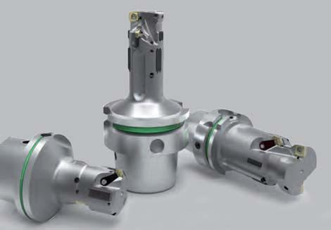
60 60

61 Reaming and Fine Boring Tools with guide pads EasyAdjust-System Tools with guide pads simple setting of tools in a minimum of time A drastic reduction in the setting time for tools with guide pad technology was the goal of the latest new development from MAPAL the EasyAdjust-System. The heart of the EasyAdjust-System is an innovative cassette that stably holds the blades with their six or four cutting edges without any play. The back taper of the minor cutting edge is already integrated into this cassette, thus eliminated the need for this adjustment. Thanks to the exact guidance of the cassette on a precision guide pin, the back taper remains unchanged even during diameter adjustments. Matching cassettes are available for different back tapers that can be selected and employed, depending on the application irrespective of the blade and the tool. Significant economic benefits In practice this system offers economic benefits: Introduction 60 System overview 62 Indexable blade 64 Handling instructions 66 The HX-blades with six useful cutting edges can be inserted quickly and precisely in cassettes with different back tapers. Tools with EasyAdjust-System only have to be adjusted in diameter. That increases process reliability at blade changes an effect that becomes all the more significant, the more blades are installed in a tool. And the time for adjustment per blade is reduced to a fraction by the new development. Advantages: Setting time drastically reduced only the diameter of the tools still has to be adjusted. Cost-effectiveness, handling and process reliability significantly increased Precision remains high 61


62 Reaming and Fine Boring Tools with guide pads EasyAdjust-System System overview Clamping jaw with threaded spindle HX blade with clamping groove Cassette The EasyAdjust-System consists of a precision cassette which holds the blade. The cassette is guided by a precision guide pin during adjustment. A clamping groove which together with the clamping jaw forms a force closure system ensures that the blade is securely retained. Tools with EasyAdjust-System only have to be adjusted in diameter. The back taper is already integrated into the cassette and remains unchanged at diameter changes. Advantages: Half the setting time for blades Exact guidance of the system on precision guide pin Back taper already integrated into the cassette Optimum cutting material utilisation thanks to blades with four and six cutting edges Precision guide pin Threaded pin and adjusting wedge Comparison of the setting times The time for adjustment per blade can be drastically reduced by the new development. New EasyAdjust-System Conventional systems 62

63 Reaming and Fine Boring Tools with guide pads EasyAdjust-System The back taper of the blade has a major influence on the bore quality. MAPAL selects the back taper of the cassette necessary for the machining application according to the demands of the material and the feed rate. Advantages: back taper Adaptation of the back taper, irrespective of blade and tool body Production of defined roughnesses thanks to different back tapers Optimum surface finish for downstream processes (for example honing) Tools with guide pads Two variants of the indexable blades The EasyAdjust-System is available with two different blade types for through bores and blind bores. HX blade TEC blade The HX blade with six cutting edges for high cost-effectiveness. Through bore Suitable for open bores. Not suitable for machining shoulders if 90 are required. The TEC blade with four cutting edges and different lead geometries for blind bore and shoulder machining. Shoulder blind bore Suitable for closed bores and machining shoulders taking into account the cutting edge length. 63
64 Reaming and Fine Boring Tools with guide pads EasyAdjust-System Article overview EasyAdjust-System with HX blades Selection Auswahlkriterien criteria Bohrungsart Type of bore ø-bereich ø-tool Graduation Abstufung range Werkzeug of der the Verjüngung* back taper* Systemgrößen sizes Schneidentyp Blade type Schneidengröße Cutting edge System- size bezeichnung designation Through bore from ø 20 B Particular demands Back taper HX 2 EAS-R-62-B D Recommended EAS-R-62-D F standard EAS-R-62-F H Particular demands EAS-R-62-H K EAS-R-62-K M EAS-R-62-M P + EAS-R-62-P R EAS-R-62-R from ø 30 B Particular demands Back taper 3 EAS-R-63-B D Recommended EAS-R-63-D F standard EAS-R-63-F H Particular demands EAS-R-63-H K EAS-R-63-K M EAS-R-63-M P + EAS-R-63-P R EAS-R-63-R * Selection by agreement with MAPAL, depending on the demands of the part. Carbide PcBN PCD P M K S K N Cutting material type HP342 CP122 HP342 HC413 HP342 HP615 FU485 PU620 Type Size HX HX 2 HX128RLB HX128RLB HX128RLB Please ask HX HX 3 HX138RLB HX138RLB HX138RLB Please ask Available from stock in Germany No stockage of standard tool (delivery time on request) 64

65 Reaming and Fine Boring Tools with guide pads EasyAdjust-System Article overview EasyAdjust-System with TEC blades Selection Auswahlkriterien criteria Bohrungsart Type of bore ø-bereich ø-tool Graduation Abstufung range Werkzeug of der the Verjüngung* back taper* Systemgrößen sizes Schneidentyp Blade type Schneidengröße Cutting edge System- size bezeichnung designation Blind bore / shoulder from ø 20 B Particular demands Back taper TEC 2 EAS-R-42-B D Recommended EAS-R-42-D F standard EAS-R-42-F H Particular demands EAS-R-42-H K EAS-R-42-K M EAS-R-42-M P + EAS-R-42-P R EAS-R-42-R from ø 30 B Particular demands Back taper 3 EAS-R-43-B D Recommended EAS-R-43-D F standard EAS-R-43-F H Particular demands EAS-R-43-H K EAS-R-43-K M EAS-R-43-M P + EAS-R-43-P R EAS-R-43-R Tools with guide pads * Selection by agreement with MAPAL, depending on the demands of the part. Carbide PcBN PCD P M K S K N Cutting material type HP342 CP140 HP342 HC413 HP342 HP615 FU485 PU620 Type Size TEC TEC TEC TEC Available from stock in Germany No stockage of standard tool (delivery time on request) 65


66 Reaming and Fine Boring Tools with guide pads EasyAdjust-System Handling instructions Replacing and setting the blade The EasyAdjust-System permits quick and easy replacement of the blades. The blades are replaced and set with μ precision in just a few steps Loosen the adjusting wedge by turning it half a turn in anti-clockwise direction using an allen key. 2 Note: Two allen keys are required. Loosen the clamping jaw by turning allen key 1 in anti-clockwise direction while turning allen key 2 in clockwise direction. 3 Push the cassette together with the adjusting wedge forward towards the tool. 1 2 Remove the blade from the cassette. 5 Replace or turn the blade and then press the blade into the cassette. 6 Note: Two allen keys are required. Tighten the clamping jaw by turning allen key 1 in clockwise direction while turning allen key 2 in anti-clockwise direction. 66


67 Reaming and Fine Boring Tools with guide pads EasyAdjust-System Clamping jaw with threaded spindle HX blade with clamping groove Cassette Clamping jaw with threaded spindle TEC blade with clamping groove Cassette Precision guide pin Threaded pin and adjusting wedge Precision guide pin Threaded pin and adjusting wedge Tools with guide pads Note: You can now proceed with either the protrusion measurement or the absolute measurement. 8 Move the measuring sensor to the highest point of the blade. Clamp the tool in the mount of a setting device. Move the measuring sensor to the highest point of the guide pad and zero the measured value at this point. 9 Set the protrusion dimension or absolute dimension of the blade by turning the threaded pin in clockwise direction using an allen key. Result: The desired protrusion or absolute dimension of the blade is set. Note: To be used only by trained personnel. 67


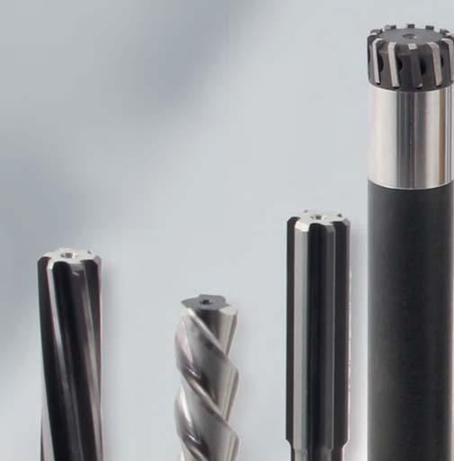
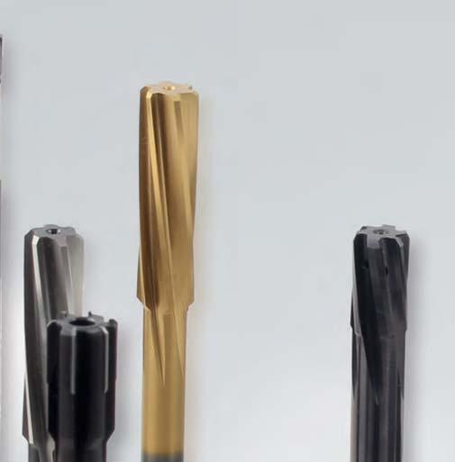
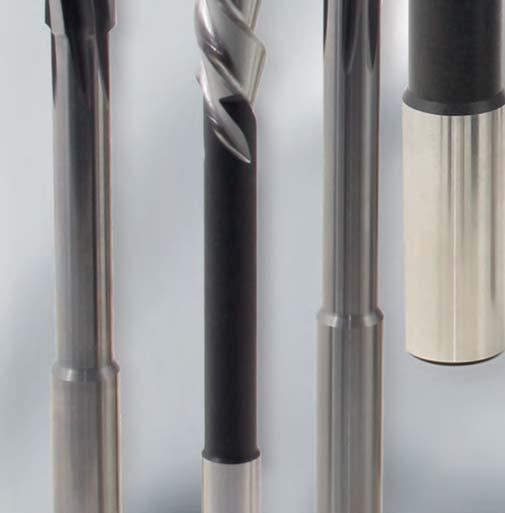
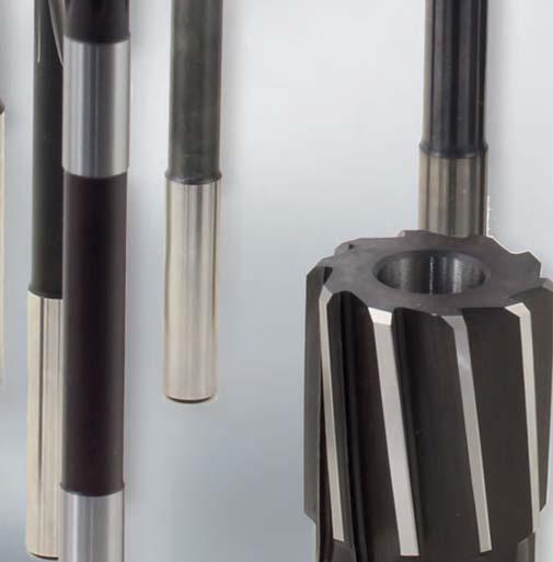
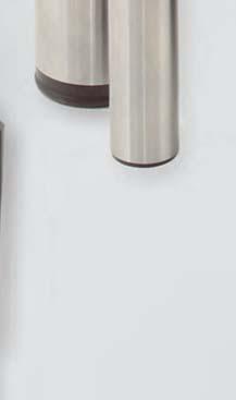
68 68


69 Reaming and Fine Boring Fixed multi-bladed reamers Fixed multi-bladed reamers Drastically reduced machining times are possible using fixed multi-bladed reamers. The multi-cutting edge permit higher feed values, which at the end of the day define the machining times. Due to specifically developed systems and the latest manufacturing technology, MAPAL also offers these tools with the highest accuracies. The product portfolio offers a wide variety that will satisfy all the requirements of the machining task. All areas are covered, from monoblock versions through to modern replaceable head systems. The standard products are complemented by special solutions which set new standards with respect to productivity. Fixed multi-bladed reamers Article overview 70 Lead geometries / rake angles 72 High-performance reamers with cylindrical shank FixReam FXR 74 MonoReam MOR 96 MonoReam Plus MRP 122 FeedPlus FPR 132 Replaceable head reamers High Performance Reamer HPR 144 Complete Performance Reamer CPR 188 High-performance reamers Machine reamers to DIN MDR and similar DIN MSR


70 Multi-bladed reamers the way to the right reamer FXR FixReam MOR MonoReam MRP MonoReamPlus Reamers of solid carbide, solid cermet and PcBN with special coatings and lead geometries above 3.00 mm diameter with internal cooling for practically all materials. Reamer system in fixed, expandable and finely adjustable versions. Diameters 8 40 mm in straight and left-hand fluted for through bore machining and straight for blind hole machining. Specially for cast iron with selective coolant supply. Reamer with HPC geometry of solid cermet and with cermet blades. From 8 mm diameter also available as an expanding version for through bore machining. FPR FeedPlus HPR High Performance Reamer CPR CPReam Maximum number of blades for maximum performance for through bores. With 6 12 mm diameter as solid carbide variant, and for mm diameter with brazed blades. Replaceable head system with axial and radial tool clamping. Simple handling, high changeover accuracy and radial run-out accuracy > 3 μm. Simple replaceable head system with taper and face connection for high stability and rigidity. Simple handling and radial run-out accuracy > 5 μm. MDR MSR DIN reamers HPR300 Machine reamers without internal cooling to DIN (MDR), and similar to DIN (MSR) with straight shank diameter for clamping in standard chucks. From 65 mm diameter 70
71 Reaming and Fine Boring Fixed multi-bladed reamers Introduction Which tool is suitable for which diameter range? Highly suitable Transitional range Complements the product groups Diameter ranges in mm 0, FXR FixReam 3,0 14,0 14,0 20,0 Modular MonoBlock MOR MonoReam MRP MonoReamPlus FPR FeedPlus HPR High-performance reamer CPR CPReam 8,0 14,0 30,0 40,0 4,0 40,0 6,0 40,0 7,0 65,0 8,0 40,0 High-performance reamers DIN sdin MDR MSR Machine reamers 0,6 100 Special HPR 300 compression ring Compression ring HPR
72 Cutting lead geometry and radial rake multi-bladed reamers Serie FXR, MOR, MPR, FPR, HPR and CPR MA CUTTING LEAD 1G Geometry Cutting lead geometry Radialrake Type Geometry Type Rake x 0A 0 25 ML 25 1E 4 1F 5 1G 6 1L 10 x ME 1N 12 1M MF MG 30 2A 2G 0 (for blind bores) 6 (for blind bores) x MY MC 3F -5 3C -2 3L -10 3Z negative variable 45 MH 45 MU x MV MI 60 MT MM 60 x MQ Type Explanation cutting material Explanation 75 MA 75 HU HP HC Carbide Carbide PVD coated Carbide CVD coated CU Cermet x 1 x 2 CP Cermet PVD coated 5 75 MW 75 /5 PU FU SU PCD PcBN HSS x = Cutting length AP HSS PVD coated 72
73 Reaming and Fine Boring Fixed multi-bladed reamers Cutting leads Series / Diameter range / Cutting lead / Cutting length Series Cutting lead Diameter range Cutting length x Series Cutting lead Diameter range Cutting length x MOR MY MU MC MG MPR MF MV MPR700 MV MG High-performance reamers FXR MV MM MT FPR MV MQ MH MH MV MG MC MI HPR MA ME ML MW x 1 =0.8 x 2 =0.5 MG MV MC MY CPR MF MT MA

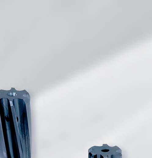

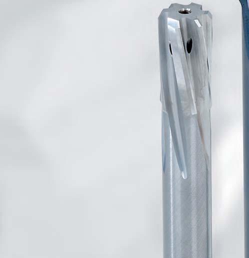
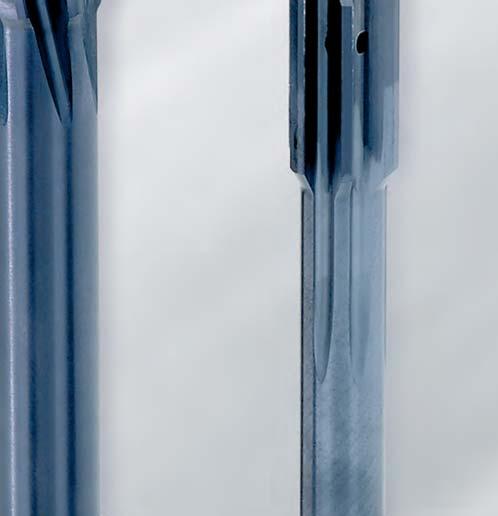
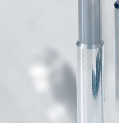
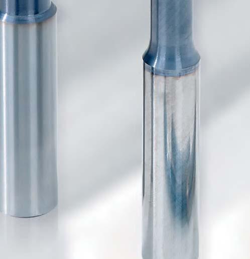

74 74


75 Reaming and Fine Boring Fixed multi-bladed reamers High-performance reamers FixReam FXR FixReam The FixReam reamer series cover a wide range of applications. By using different cutting materials and coatings in this manner, it is possible to machine almost any material with these reamers. The diameter range of 3-20 mm extends to all types. Of course for special cases outside this range or for complete machining, MAPAL FixReam reamers are available as custom tools. The short version is designed precisely for these conditions. In addition, the new series now allows extremely hard cutting materials such as PCD or PcBN to be used for reaming, and that from a diameter of only 0.98 mm. Article overview 78 FixReam FXR FixReam FXR512, solid cermet 83 FixReam FXR FixReam FXR503, short 90 FixReam FXR Cutting data 95 High-performance reamers 75


76 Solid carbide high-performance reamers FixReam for high feed and short machining times and castings is available from stock in numerous diameters. The programme includes reamers stepped in increments of 0.01 mm with coated or uncoated design. Special variants are also available on short notice. Another advantage of fixed multi-bladed reamers is that they are very easy to handle iwhen use. Bore qualities in the range of IT 7 can be achieved with no adjustments and with process reliability. This is in partly due to the high manufacturing quality of FixReam reamers. These reamer, produced in ultramodern production facilities to meet high quality standards, have been used for demanding machining tasks for many years with excellent results. For more than 60 years MAPAL has been using precision tools for fine machining of bores to meet the highest quality standards of machining with geometrically defined cutting edges. The MAPAL tool portfolio offers a unique range of reaming and fine boring tools for this purpose with various cutting systems. In addition to designs with guide pads, an entire series of fixed multi-bladed reamers is also available. Fixed reamers are used in fine machining of bores especially when short machining times and high productivity are important. For example, moderate cutting speeds due to the material can be compensated for in mass production of steel and cast parts by high feed rates. Depending on the diameter, MAPAL FixReam reamers have between four and eight cutting edges, which allows them to reach the required high feed rates. According to the diameter, the MAPAL high performance reamers have between four and eight cutting edges and through this achieve the appropriate high feed rate speeds. Reamers made of solid carbide or solid cermet. These series feature different coatings and internal coolant supply. The standard programme for universal application and highspeed machining of steel, iron, Alu Advantages: Optimum geometries for every material High availability from stock 76


77 Reaming and Fine Boring Fixed multi-bladed reamers High-performance reamers FixReam FXR Internal coolant supply Cutting edges are supplied with cooling lubricant even in deep bores by a sintered central cooling hole. The result is longer tool service life and good chip removal. Solid carbide body This type of tool is based on sturdy blanks made of premium, wear-resistant, finest grade carbide. This basic material features good flexural strength and high hardness. Radial run-out accuracy Radial run-out is an important factor in determining quality and tool life. The solid carbide body ensures optimum rigidity in the manufacturing process. This is essential for uniform circularity of the tool extending over the cutting edge, arc land chamfer and shank. Even on reground tools there should be no reduction in quality. Reduced number of shank dimensions A very small number of shank dimensions ensures use of the entire diameter range in just a few connections and without any reducing sleeves. The shanks have no clamping surfaces and are practically free of imbalance. Optimised cutting geometry The geometry of the reamers has been fine-tuned for high-performance reaming. Together with the tool body material, this suppresses the tendency to chatter, even at increased cutting speeds. Tools with modified geometry and coatings are available on short notice for machining difficult materials. High-performance reamers Coating for high performance Coated tools are a useful option for further extending tool life and preventing build-up on cutting edges. Various modern coatings are available depending on the material being machined to ensure better utilisation of the tool. FixReam Short - the short design for automated lathes Specially designed for use on automated lathes, it is very helpful when united space is available to have an extra short reamer on hand. The FixReam Short is designed for machines with a very small working area. The series are available both with and without internal coolant supply. Extremely hard cutting materials With this new series, extremely hard PcBN can be used for reaming above a diameter of 0.98 mm, and above 3 mm with internal cooling. The cutting material is applied as a layer to the face of a body made of solid carbide and the cutting edge geometry is produced using newly developed methods. These reamers achieve a significant increase in the cutting values and, in particular, in the tool lives when machining parts of, for example, sintered aluminium or hardened steel. As a special version, these reamers are also available with PCD tips. 77
78 Article overview FixReam Ordering example Series Type of bore Material Coolant supply Fixed version of Solid carbide, solid cermet or short version P K M S N1 H 505 Solid carbide K H 505 PcBN P K 503 short N2 H 500 Solid carbide K H 500 PcBN P K M S N1 510 Solid carbide P K2 512 Solid cermet Tool data FXR ød1 l 1 l 3 ød 2 l 2 l 4 z FXR510 z FXR FXR ød1 l 1 l 3 ød 2 l 2 l 4 z FXR FXR Lead 510, 505 Cut Solid carbide Lead 512 Cut Solid cermet Lead 500 Cut Solid carbide Lead 500, 505 PcBN Cut Lead 503 short Cut Ordering example SERIES DIAMETER 78 FXR 500G ø FixReam Type of bore: 0 2 = Through bore 3 5 = Blind bore Flute helix angle on the blades: 0 = Straight-fluted 1 = Left-hand fluted Version: 5: Solid carbide Solid cermet Detail tool diameter (Position only used by G version) Bore diameter 0
79 Reaming and Fine Boring Fixed multi-bladed reamers High-performance reamers FixReam FXR Tool dimensions FXR510, FXR512 FXR500 FXR505 d 2 P Non-alloy steels, cast-steel, alloy steels l 2 FXR503 short M K1 K2 K3 N1 N2 S H Stainless, rust and acid-resistant steels l1 l 3 l 4 Grey cast iron GG d Spheroidal cast iron GGG40 50 Spheroidal/ vermicular cast iron GGG60 80 Bronze, copper, brass Aluminium CFK / GFK < HRC63 High-performance reamers MV0A MG1M MT0A MF1M MV0A MG1M MV0A MG1M MV0A MG1M MV0A MG1M MV0A MV0A MG1M MT0A HP145 HU612 HP145 HP145 HP145 HP145 HP145 HP145 HP145 HP145 HP145 HU612 HU612 HP622 HU612 HC614 HC614 HP141 MG1M CU154 MG1M CU154 MG0A HP622 MF0A HP141 MI3F MH3F MI3F MH3F MI3F MH3F MI3F MH3F FU840 FU840 FU840 FU840 FU840 FU840 FU840 FU840 MC1F MC1F MC1F MC1F HP145 HP145 HP145 HP145 FIT CUTTING LEAD [Lead] CUTTING MATERIAL [Cut] +4 M G 0 A - H P IT or dimensions in μm (example: ) Cutting lead geometry and rake angle: MG0A MG1M MF1M MV0A MH3F MI3F MT0A MF0A MC1F Explanation of cutting lead geometry on page 72/73. Cutting material: HP145 HU612 CU154 FU840 HP622 HC614 HP141 79
80 Reaming and Fine Boring Fixed multi-bladed reamers High-performance reamers FixReam FXR FixReam FXR510 Solid carbide H7 d 2 h 6 Cutting material suggestion l 2 l 1 l 3 l 4 P M K1 K2 K3 N1 Cu/Zn/Mg S H Lead MG1M MF1M MG1M MG1M MG1M Cut HP145 HP145 HP145 HU612 HC614 Dimensions Specification* Order No. ø Tolerance l 1 l 2 l 3 l 4 ø d 2 z MG1M MG1M MF1M MG1M HU612 HP145 HP145 HC H FXR510ø3H7[Lead]-[Cut] Please ask Please ask 3.20 H FXR510ø3.2H7[Lead]-[Cut] Please ask Please ask 3.50 H FXR510ø3.5H7[Lead]-[Cut] Please ask Please ask 4.00 H FXR510ø4H7[Lead]-[Cut] H FXR510ø4.5H7[Lead]-[Cut] H FXR510ø5H7[Lead]-[Cut] H FXR510ø5.5H7[Lead]-[Cut] H FXR510ø6H7[Lead]-[Cut] H FXR510ø6.5H7[Lead]-[Cut] H FXR510ø7H7[Lead]-[Cut] H FXR510ø7.5H7[Lead]-[Cut] H FXR510ø8H7[Lead]-[Cut] H FXR510ø8.5H7[Lead]-[Cut] H FXR510ø9H7[Lead]-[Cut] H FXR510ø9.5H7[Lead]-[Cut] H FXR510ø10H7[Lead]-[Cut] H FXR510ø10.5H7[Lead]-[Cut] H FXR510ø11H7[Lead]-[Cut] H FXR510ø11.5H7[Lead]-[Cut] H FXR510ø12H7[Lead]-[Cut] H FXR510ø13H7[Lead]-[Cut] H FXR510ø14H7[Lead]-[Cut] H FXR510ø15H7[Lead]-[Cut] H FXR510ø16H7[Lead]-[Cut] H FXR510ø17H7[Lead]-[Cut] H FXR510ø18H7[Lead]-[Cut] H FXR510ø19H7[Lead]-[Cut] H FXR510ø20H7[Lead]-[Cut] Please order intermediate sizes and tolerances other than H7 using the configuration description at the beginning of chapter FXR high-performance reamers. *Please complete the specification by indicating the lead [Lead] and cutting material [Cut] (see ordering example at the beginning of the chapter). 80
81 Reaming and Fine Boring Fixed multi-bladed reamers High-performance reamers FixReam FXR FixReam FXR510G Solid carbide +4 μm d 2 h 6 Cutting material suggestion l 2 l 1 l 3 l 4 P M K1 K2 K3 N1 Cu/Zn/Mg S H Lead MG1M MF1M MG1M MG1M Cut HP145 HP145 HP145 HU612 Dimensions Specification* Order No. ø Tolerance l 1 l 2 l 3 l 4 ø d 2 z MG1M MG1M MF1M HU612 HP145 HP FXR510Gø3.97+4[Lead]-[Cut] FXR510Gø3.98+4[Lead]-[Cut] FXR510Gø3.99+4[Lead]-[Cut] FXR510Gø4.01+4[Lead]-[Cut] FXR510Gø4.02+4[Lead]-[Cut] FXR510Gø4.03+4[Lead]-[Cut] FXR510Gø4.97+4[Lead]-[Cut] FXR510Gø4.98+4[Lead]-[Cut] FXR510Gø4.99+4[Lead]-[Cut] FXR510Gø5.01+4[Lead]-[Cut] FXR510Gø5.02+4[Lead]-[Cut] FXR510Gø5.03+4[Lead]-[Cut] FXR510Gø5.97+4[Lead]-[Cut] FXR510Gø5.98+4[Lead]-[Cut] FXR510Gø5.99+4[Lead]-[Cut] FXR510Gø6.01+4[Lead]-[Cut] FXR510Gø6.02+4[Lead]-[Cut] FXR510Gø6.03+4[Lead]-[Cut] FXR510Gø7.97+4[Lead]-[Cut] FXR510Gø7.98+4[Lead]-[Cut] FXR510Gø7.99+4[Lead]-[Cut] FXR510Gø8.01+4[Lead]-[Cut] FXR510Gø8.02+4[Lead]-[Cut] FXR510Gø8.03+4[Lead]-[Cut] FXR510Gø9.97+4[Lead]-[Cut] FXR510Gø9.98+4[Lead]-[Cut] FXR510Gø9.99+4[Lead]-[Cut] FXR510Gø [Lead]-[Cut] Please order intermediate sizes using the configuration description at the beginning of chapter FXR high-performance reamers. *Please complete the specification by indicating the lead [Lead] and cutting material [Cut] (see ordering example at the beginning of the chapter). High-performance reamers 81
82 Reaming and Fine Boring Fixed multi-bladed reamers High-performance reamers FixReam FXR FixReam FXR510G Solid carbide +4 μm d 2 h 6 Cutting material suggestion l 2 l 1 l 3 l 4 P M K1 K2 K3 N1 Cu/Zn/Mg S H Lead MG1M MF1M MG1M MG1M Cut HP145 HP145 HP145 HU612 Dimensions Specification* Order No. ø Tolerance l 1 l 2 l 3 l 4 ø d 2 z MG1M MG1M MF1M HU612 HP145 HP FXR510Gø [Lead]-[Cut] FXR510Gø [Lead]-[Cut] FXR510Gø [Lead]-[Cut] FXR510Gø [Lead]-[Cut] FXR510Gø [Lead]-[Cut] FXR510Gø [Lead]-[Cut] FXR510Gø [Lead]-[Cut] FXR510Gø [Lead]-[Cut] Please order intermediate sizes using the configuration description at the beginning of chapter FXR high-performance reamers. *Please complete the specification by indicating the lead [Lead] and cutting material [Cut] (see ordering example at the beginning of the chapter). 82
83 Reaming and Fine Boring Fixed multi-bladed reamers High-performance reamers FixReam FXR FixReam FXR512 Solid cermet H7 d 2 h 6 Cutting material suggestion l 2 l 3 l 4 P M K1 K2 K3 N S H l 1 Lead MG1M MG1M Cut CU154 CU154 Dimensions Specification Order No. ø Tolerance l 1 l 2 l 3 l 4 ø d 2 z 4.00 H FXR512ø4H7MG1M-CU H FXR512ø4.5H7MG1M-CU H FXR512ø5H7MG1M-CU H FXR512ø5.5H7MG1M-CU H FXR512ø6H7MG1M-CU H FXR512ø6.5H7MG1M-CU H FXR512ø7H7MG1M-CU H FXR512ø7.5H7MG1M-CU H FXR512ø8H7MG1M-CU H FXR512ø8.5H7MG1M-CU H FXR512ø9H7MG1M-CU H FXR512ø9.5H7MG1M-CU H FXR512ø10H7MG1M-CU H FXR512ø10.5H7MG1M-CU H FXR512ø11H7MG1M-CU H FXR512ø11.5H7MG1M-CU H FXR512ø12H7MG1M-CU Please order intermediate sizes and tolerances other than H7 using the configuration description at the beginning of chapter FXR high-performance reamers. High-performance reamers 83
84 Reaming and Fine Boring Fixed multi-bladed reamers High-performance reamers FixReam FXR FixReam FXR512G Solid cermet +4 μm d 2 h 6 Cutting material suggestion l 2 l 3 l 4 P M K1 K2 K3 N S H l 1 Lead MG1M MG1M Cut CU154 CU154 Dimensions Specification Order No. ø Tolerance l 1 l 2 l 3 l 4 ø d 2 z FXR512Gø3.97+4MG1M-CU154 Please ask FXR512Gø3.98+4MG1M-CU FXR512Gø3.99+4MG1M-CU FXR512Gø4.01+4MG1M-CU FXR512Gø4.02+4MG1M-CU FXR512Gø4.03+4MG1M-CU FXR512Gø4.97+4MG1M-CU FXR512Gø4.98+4MG1M-CU FXR512Gø4.99+4MG1M-CU FXR512Gø5.01+4MG1M-CU FXR512Gø5.02+4MG1M-CU FXR512Gø5.03+4MG1M-CU FXR512Gø5.97+4MG1M-CU FXR512Gø MG1M-CU FXR512Gø5.99+4MG1M-CU FXR512Gø6.01+4MG1M-CU FXR512Gø6.02+4MG1M-CU FXR512Gø6.03+4MG1M-CU FXR512Gø7.97+4MG1M-CU FXR512Gø7.98+4MG1M-CU FXR512Gø7.99+4MG1M-CU FXR512Gø8.01+4MG1M-CU FXR512Gø8.02+4MG1M-CU FXR512Gø8.03+4MG1M-CU FXR512Gø9.97+4MG1M-CU FXR512Gø9.98+4MG1M-CU FXR512Gø9.99+4MG1M-CU FXR512Gø MG1M-CU FXR512Gø MG1M-CU FXR512Gø MG1M-CU FXR512Gø MG1M-CU FXR512Gø MG1M-CU Please order intermediate sizes using the configuration description at the beginning of chapter FXR high-performance reamers. 84
85 Reaming and Fine Boring Fixed multi-bladed reamers High-performance reamers FixReam FXR FixReam FXR512G Solid cermet +4 μm d 2 h 6 Cutting material suggestion l 2 l 3 l 4 P M K1 K2 K3 N S H l 1 Lead MG1M MG1M Cut CU154 CU154 Dimensions Specification Order No. ø Tolerance l 1 l 2 l 3 l 4 ø d 2 z FXR512Gø MG1M-CU FXR512Gø MG1M-CU FXR512Gø MG1M-CU FXR512Gø MG1M-CU Please order intermediate sizes using the configuration description at the beginning of chapter FXR high-performance reamers. High-performance reamers 85
86 Reaming and Fine Boring Fixed multi-bladed reamers High-performance reamers FixReam FXR FixReam FXR500 Solid carbide H7 d 2 h 6 Cutting material suggestion l 4 l 2 l1 l 3 P M K1 K2 K3 N2 Alu S H Lead MG0A MF0A Cut HP622 HP141 Dimensions Specification* Order No. ø Tolerance l 1 l 2 l 3 l 4 ø d 2 z MG0A HP622 MF0A HP H FXR500ø4H7[Lead]-[Cut] H FXR500ø4.5H7[Lead]-[Cut] H FXR500ø5H7[Lead]-[Cut] H FXR500ø5.5H7[Lead]-[Cut] H FXR500ø6H7[Lead]-[Cut] H FXR500ø6.5H7[Lead]-[Cut] H FXR500ø7H7[Lead]-[Cut] H FXR500ø7.5H7[Lead]-[Cut] H FXR500ø8H7[Lead]-[Cut] H FXR500ø8.5H7[Lead]-[Cut] H FXR500ø9H7[Lead]-[Cut] H FXR500ø9.5H7[Lead]-[Cut] H FXR500ø10H7[Lead]-[Cut] H FXR500ø10.5H7[Lead]-[Cut] H FXR500ø11H7[Lead]-[Cut] H FXR500ø11.5H7[Lead]-[Cut] H FXR500ø12H7[Lead]-[Cut] H FXR500ø13H7[Lead]-[Cut] H FXR500ø14H7[Lead]-[Cut] H FXR500ø15H7[Lead]-[Cut] H FXR500ø16H7[Lead]-[Cut] H FXR500ø17H7[Lead]-[Cut] H FXR500ø18H7[Lead]-[Cut] H FXR500ø19H7[Lead]-[Cut] H FXR500ø20H7[Lead]-[Cut] Please order intermediate sizes and tolerances other than H7 using the configuration description at the beginning of chapter FXR high-performance reamers. *Please complete the specification by indicating the lead [Lead] and cutting material [Cut] (see ordering example at the beginning of the chapter). 86
87 Reaming and Fine Boring Fixed multi-bladed reamers High-performance reamers FixReam FXR FixReam FXR500G Solid carbide +4 μm d 2 h 6 Cutting material suggestion l 4 l 2 l1 l 3 P M K1 K2 K3 N S H Lead MF0A Cut HP141 Dimensions Specification Order No. ø Tolerance l 1 l 2 l 3 l 4 ø d 2 z FXR500Gø3.97+4MF0A-HP FXR500Gø3.98+4MF0A-HP FXR500Gø3.99+4MF0A-HP FXR500Gø4.01+4MF0A-HP FXR500Gø4.02+4MF0A-HP FXR500Gø4.03+4MF0A-HP FXR500Gø4.97+4MF0A-HP FXR500Gø4.98+4MF0A-HP FXR500Gø4.99+4MF0A-HP FXR500Gø5.01+4MF0A-HP FXR500Gø5.02+4MF0A-HP FXR500Gø5.03+4MF0A-HP FXR500Gø5.97+4MF0A-HP FXR500Gø5.98+4MF0A-HP FXR500Gø5.99+4MF0A-HP FXR500Gø6.01+4MF0A-HP FXR500Gø6.02+4MF0A-HP FXR500Gø6.03+4MF0A-HP FXR500Gø7.97+4MF0A-HP FXR500Gø7.98+4MF0A-HP FXR500Gø7.99+4MF0A-HP FXR500Gø8.01+4MF0A-HP FXR500Gø8.02+4MF0A-HP FXR500Gø8.03+4MF0A-HP FXR500Gø9.97+4MF0A-HP FXR500Gø9.98+4MF0A-HP FXR500Gø9.99+4MF0A-HP FXR500Gø MF0A-HP FXR500Gø MF0A-HP FXR500Gø MF0A-HP FXR500Gø MF0A-HP FXR500Gø MF0A-HP FXR500Gø MF0A-HP High-performance reamers Please order intermediate sizes using the configuration description at the beginning of chapter FXR high-performance reamers. 87
88 Reaming and Fine Boring Fixed multi-bladed reamers High-performance reamers FixReam FXR FixReam FXR500G Solid carbide +4 μm d 2 h 6 Cutting material suggestion l 4 l 2 l1 l 3 P M K1 K2 K3 N S H Lead MF0A Cut HP141 Dimensions Specification Order No. ø Tolerance l 1 l 2 l 3 l 4 ø d 2 z FXR500Gø MF0A-HP FXR500Gø MF0A-HP FXR500Gø MF0A-HP Please order intermediate sizes using the configuration description at the beginning of chapter FXR high-performance reamers. 88
89 Reaming and Fine Boring Fixed multi-bladed reamers High-performance reamers FixReam FXR FixReam FXR500 PcBN PcBN head H7 d 2 h 6 Cutting material suggestion l 2 l1 l 3 l 4 P M K1 K2 K3 N S H Lead MH3F MH3F Cut FU840 FU840 Dimensions Specification Order No. ø Tolerance l 1 l 2 l 3 l 4 ø d 2 z 3.00 H FXR500ø3H7MH3F-FU H FXR500ø3.5H7MH3F-FU H FXR500ø4H7MH3F-FU H FXR500ø4.5H7MH3F-FU H FXR500ø5H7MH3F-FU H FXR500ø5.5H7MH3F-FU H FXR500ø6H7MH3F-FU H FXR500ø6.5H7MH3F-FU H FXR500ø7H7MH3F-FU H FXR500ø7.5H7MH3F-FU H FXR500ø8H7MH3F-FU H FXR500ø8.5H7MH3F-FU H FXR500ø9H7MH3F-FU H FXR500ø9.5H7MH3F-FU H FXR500ø10H7MH3F-FU Please order intermediate sizes and tolerances other than H7 using the configuration description at the beginning of chapter FXR high-performance reamers. High-performance reamers Attention: Smaller ø 3.00 on enquiry and without internal coolant. 89
90 Reaming and Fine Boring Fixed multi-bladed reamers High-performance reamers FixReam FXR FixReam FXR503 short Particularly suitable for machining on automated lathes, for short bores Solid carbide H7 Cutting material suggestion d 2 h 6 l 2 l 3 l 4 P M K1 K2 K3 N S H l 1 Lead MC1F MC1F Cut HP145 HP145 Dimensions Specification Order No. ø Tolerance l 1 l 2 l 3 l 4 ø d 2 z 3.00 H FXR503ø3H7MC1F-HP H FXR503ø3.2H7MC1F-HP H FXR503ø3.5H7MC1F-HP H FXR503ø4H7MC1F-HP H FXR503ø4.5H7MC1F-HP H FXR503ø5H7MC1F-HP H FXR503ø5.5H7MC1F-HP H FXR503ø6H7MC1F-HP H FXR503ø6.5H7MC1F-HP H FXR503ø7H7MC1F-HP H FXR503ø7.5H7MC1F-HP H FXR503ø8H7MC1F-HP H FXR503ø8.5H7MC1F-HP H FXR503ø9H7MC1F-HP H FXR503ø9.5H7MC1F-HP H FXR503ø10H7MC1F-HP H FXR503ø10.5H7MC1F-HP H FXR503ø11H7MC1F-HP H FXR503ø11.5H7MC1F-HP H FXR503ø12H7MC1F-HP H FXR503ø13H7MC1F-HP H FXR503ø14H7MC1F-HP H FXR503ø15H7MC1F-HP H FXR503ø16H7MC1F-HP H FXR503ø17H7MC1F-HP H FXR503ø18H7MC1F-HP H FXR503ø19H7MC1F-HP H FXR503ø20H7MC1F-HP Please order intermediate sizes and tolerances other than H7 using the configuration description at the beginning of chapter FXR high-performance reamers. 90
91 Reaming and Fine Boring Fixed multi-bladed reamers High-performance reamers FixReam FXR FixReam FXR505 Solid carbide H7 d 2 h 6 Cutting material suggestion l 2 l1 l 4 l 3 P M K1 K2 K3 N1 N2 S H Lead MV0A MT0A MV0A MV0A MV0A MV0A MT0A Cut HP145 HU612 HP145 HP145 HU612 HP622 HU612 HC614 HP141 Dimensions Specification* Order No. ø Tol. l 1 l 2 l 3 l 4 ø d 2 z MV0A MV0A MT0A MV0A MT0A MV0A HU612 HP145 HP145 HC614 HP141 HP H FXR505ø3H7[Lead]-[Cut] Please ask H FXR505ø3.2H7[Lead]-[Cut] Please ask H FXR505ø3.5H7[Lead]-[Cut] Please ask H FXR505ø4H7[Lead]-[Cut] H FXR505ø4.5H7[Lead]-[Cut] H FXR505ø5H7[Lead]-[Cut] H FXR505ø5.5H7[Lead]-[Cut] H FXR505ø6H7[Lead]-[Cut] H FXR505ø6.5H7[Lead]-[Cut] H FXR505ø7H7[Lead]-[Cut] H FXR505ø7.5H7[Lead]-[Cut] H FXR505ø8H7[Lead]-[Cut] H FXR505ø8.5H7[Lead]-[Cut] H FXR505ø9H7[Lead]-[Cut] H FXR505ø9.5H7[Lead]-[Cut] H FXR505ø10H7[Lead]-[Cut] H FXR505ø10.5H7[Lead]-[Cut] H FXR505ø11H7[Lead]-[Cut] H FXR505ø11.5H7[Lead]-[Cut] H FXR505ø12H7[Lead]-[Cut] H FXR505ø13H7[Lead]-[Cut] H FXR505ø14H7[Lead]-[Cut] H FXR505ø15H7[Lead]-[Cut] H FXR505ø16H7[Lead]-[Cut] H FXR505ø17H7[Lead]-[Cut] H FXR505ø18H7[Lead]-[Cut] H FXR505ø19H7[Lead]-[Cut] H FXR505ø20H7[Lead]-[Cut] Please order intermediate sizes and tolerances other than H7 using the configuration description at the beginning of chapter FXR high-performance reamers. *Please complete the specification by indicating the lead [Lead] and cutting material [Cut] (see ordering example at the beginning of the chapter). High-performance reamers 91
92 Reaming and Fine Boring Fixed multi-bladed reamers High-performance reamers FixReam FXR FixReam FXR505G Solid carbide +4 μm d 2 h 6 Cutting material suggestion l 2 l1 l 3 l 4 P M K1 K2 K3 N1 N2 S H Lead MV0A MT0A MV0A MV0A MV0A MT0A Cut HP145 HP145 HP145 HU612 HU612 HP141 Dimensions Specification* Order No. ø Tolerance l 1 l 2 l 3 l 4 ø d 2 z MV0A MV0A MT0A MT0A HU612 HP145 HP145 HP FXR505Gø3.97+4[Lead]-[Cut] FXR505Gø3.98+4[Lead]-[Cut] FXR505Gø3.99+4[Lead]-[Cut] FXR505Gø4.01+4[Lead]-[Cut] FXR505Gø4.02+4[Lead]-[Cut] FXR505Gø4.03+4[Lead]-[Cut] FXR505Gø4.97+4[Lead]-[Cut] FXR505Gø4.98+4[Lead]-[Cut] FXR505Gø4.99+4[Lead]-[Cut] FXR505Gø5.01+4[Lead]-[Cut] FXR505Gø5.02+4[Lead]-[Cut] FXR505Gø5.03+4[Lead]-[Cut] FXR505Gø5.97+4[Lead]-[Cut] FXR505Gø5.98+4[Lead]-[Cut] FXR505Gø5.99+4[Lead]-[Cut] FXR505Gø6.01+4[Lead]-[Cut] FXR505Gø6.02+4[Lead]-[Cut] FXR505Gø6.03+4[Lead]-[Cut] FXR505Gø7.97+4[Lead]-[Cut] FXR505Gø7.98+4[Lead]-[Cut] FXR505Gø7.99+4[Lead]-[Cut] FXR505Gø8.01+4[Lead]-[Cut] FXR505Gø8.02+4[Lead]-[Cut] FXR505Gø8.03+4[Lead]-[Cut] FXR505Gø9.97+4[Lead]-[Cut] FXR505Gø9.98+4[Lead]-[Cut] FXR505Gø9.99+4[Lead]-[Cut] FXR505Gø [Lead]-[Cut] Please order intermediate sizes using the configuration description at the beginning of chapter FXR high-performance reamers. *Please complete the specification by indicating the lead [Lead] and cutting material [Cut] (see ordering example at the beginning of the chapter). 92
93 Reaming and Fine Boring Fixed multi-bladed reamers High-performance reamers FixReam FXR FixReam FXR505G Solid carbide +4 μm d 2 h 6 Cutting material suggestion l 2 l1 l 3 l 4 P M K1 K2 K3 N1 N2 S H Lead MV0A MT0A MV0A MV0A MV0A MT0A Cut HP145 HP145 HP145 HU612 HU612 HP141 Dimensions Specification* Order No. ø Tolerance l 1 l 2 l 3 l 4 ø d 2 z MV0A MV0A MT0A MT0A HU612 HP145 HP145 HP FXR505Gø [Lead]-[Cut] FXR505Gø [Lead]-[Cut] FXR505Gø [Lead]-[Cut] FXR505Gø [Lead]-[Cut] FXR505Gø [Lead]-[Cut] FXR505Gø [Lead]-[Cut] FXR505Gø [Lead]-[Cut] FXR505Gø [Lead]-[Cut] Please order intermediate sizes using the configuration description at the beginning of chapter FXR high-performance reamers. *Please complete the specification by indicating the lead [Lead] and cutting material [Cut] (see ordering example at the beginning of the chapter). High-performance reamers 93
94 Reaming and Fine Boring Fixed multi-bladed reamers High-performance reamers FixReam FXR FixReam FXR505 PcBN PcBN head H7 d 2 h 6 Cutting material suggestion l 4 l 2 l1 l 3 P M K1 K2 K3 N S H Lead MI3F MI3F Cut FU840 FU840 Dimensions Specification Order No. ø Tolerance l 1 l 2 l 3 l 4 ø d 2 z 3.00 H FXR505ø3H7MI3F-FU H FXR505ø3.5H7MI3F-FU H FXR505ø4H7MI3F-FU H FXR505ø4.5H7MI3F-FU H FXR505ø5H7MI3F-FU H FXR505ø5.5H7MI3F-FU H FXR505ø6H7MI3F-FU H FXR505ø6.5H7MI3F-FU H FXR505ø7H7MI3F-FU H FXR505ø7.5H7MI3F-FU H FXR505ø8H7MI3F-FU H FXR505ø8.5H7MI3F-FU H FXR505ø9H7MI3F-FU H FXR505ø9.5H7MI3F-FU H FXR505ø10H7MI3F-FU Please order intermediate sizes and tolerances other than H7 using the configuration description at the beginning of chapter FXR high-performance reamers. Attention: Smaller ø 3.00 on enquiry and without internal coolant. 94
95 Reaming and Fine Boring Fixed multi-bladed reamers High-performance reamers FixReam FXR Cutting data FixReam FXR Cutting material Material Machining data CU HP* HP HP FU* HP FU* CU* HP FU* HU HP HU HP HP P M K N1 N2 N2 S H *Cutting data for these cutting materials on request Steel, < 700 N/mm² Steel, N/mm² Steel, N/mm² VA < 700 N/mm² VA > 700 N/mm² Grey cast iron (GG) Spheroidal graphite cast iron (bis GGG 50) Spheroidal graphite cast iron (> GGG 50) Cu / Zn / Mg-alloy Plastics soft Plastics heavy Alu-casting alloy (Si < 7%) Alu-casting alloy (Si > 7%) Alu-casting alloy (Si < 7%) Alu-casting alloy (Si > 7%) Titanium Hardened materials < 63 HRC ø [mm] < v c [m/min] f [mm/u] 0,08-0,12 0,1-0,4 0,3-0,8 0,5-1,0 0,8-1,2 allowance a 0,1-0,15 0,15-0,2 0,2-0,3 0,2-0,3 0,2-0,3 v c [m/min] f [mm/u] 0,08-0,12 0,1-0,4 0,3-0,8 0,5-1,0 0,8-1,2 allowance a 0,1-0,15 0,15-0,2 0,2-0,3 0,2-0,3 0,2-0,3 v c [m/min] f [mm/u] 0,08-0,12 0,1-0,3 0,3-0,6 0,3-0,8 0,5-1,0 allowance a 0,08-0,12 0,1-0,2 0,2-0,3 0,2-0,3 0,2-0,3 v c [m/min] f [mm/u] 0,1-0,15 0,15-0,2 0,3-0,5 0,4-0,6 0,5-1,0 allowance a 0,05-0,1 0,1-0,15 0,1-0,2 0,15-0,2 0,15-0,25 v c [m/min] f [mm/u] 0,1-0,15 0,15-0,2 0,3-0,5 0,4-0,6 0,5-1,0 allowance a 0,05-0,1 0,1-0,15 0,1-0,2 0,15-0,2 0,15-0,25 v c [m/min] f [mm/u] 0,3-0,5 0,4-1,0 0,6-1,4 0,8-2,2 0,8-2,2 allowance a 0,1-0,15 0,15-0,2 0,15-0,25 0,2-0,3 0,2-0,3 v c [m/min] f [mm/u] 0,3-0,5 0,4-1,0 0,6-1,4 0,8-2,2 0,8-2,2 allowance a 0,1-0,15 0,15-0,2 0,15-0,25 0,2-0,3 0,2-0,3 v c [m/min] f [mm/u] 0,3-0,5 0,4-1,0 0,6-1,4 0,8-2,2 0,8-2,2 allowance a 0,1-0,15 0,15-0,2 0,15-0,25 0,2-0,3 0,2-0,3 v c [m/min] f [mm/u] 0,1-0,16 0,15-0,2 0,15-0,3 0,25-0,35 0,25-0,4 allowance a 0,1-0,15 0,15-0,2 0,15-0,2 0,2-0,3 0,2-0,3 v c [m/min] f [mm/u] 0,12-0,16 0,15-0,2 0,15-0,3 0,25-0,35 0,25-0,4 allowance a 0,1-0,15 0,15-0,2 0,15-0,2 0,2-0,3 0,2-0,3 v c [m/min] f [mm/u] 0,12-0,16 0,15-0,2 0,15-0,3 0,25-0,35 0,25-0,4 allowance a 0,1-0,15 0,15-0,2 0,15-0,2 0,2-0,3 0,2-0,3 v c [m/min] f [mm/u] 0,6-0,8 1,0-1,5 1,2-2,0 1,5-2,2 1,5-2,2 allowance a 0,1-0,15 0,2-0,3 0,2-0,3 0,25-0,35 0,3-0,4 v c [m/min] f [mm/u] 0,6-0,8 1,0-1,5 1,2-2,0 1,5-2,2 1,5-2,2 allowance a 0,1-0,15 0,2-0,3 0,2-0,3 0,25-0,35 0,3-0,4 v c [m/min] f [mm/u] 0,12-0,16 0,15-0,2 0,15-0,3 0,25-0,35 0,25-0,4 allowance a 0,1-0,15 0,15-0,2 0,15-0,2 0,2-0,3 0,2-0,3 v c [m/min] f [mm/u] 0,15-0,16 0,15-0,2 0,15-0,3 0,25-0,35 0,25-0,4 allowance a 0,1-0,15 0,15-0,2 0,15-0,2 0,2-0,3 0,2-0,3 v c [m/min] f [mm/u] - - 0,4-0,6 1,4-2,8 1,4-3,6 allowance a - - 0,1-0,2 0,15-0,25 0,15-0,25 v c [m/min] Please enquire Please enquire Please enquire Please enquire Please enquire f [mm/u] Please enquire Please enquire Please enquire Please enquire Please enquire allowance a Please enquire Please enquire Please enquire Please enquire Please enquire 95 High-performance reamers

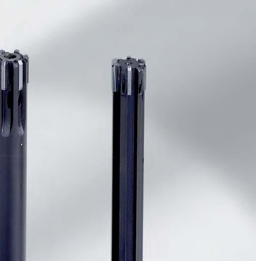

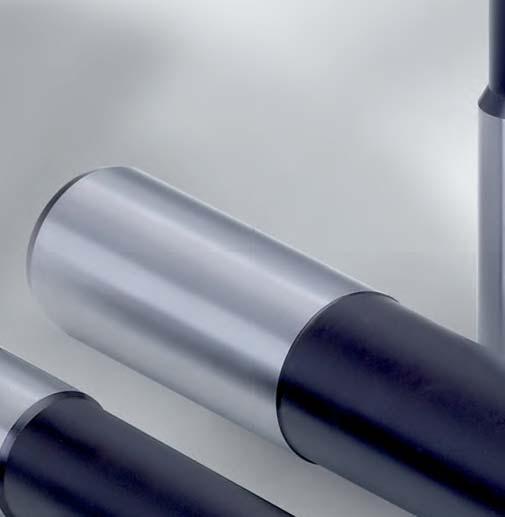
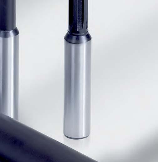
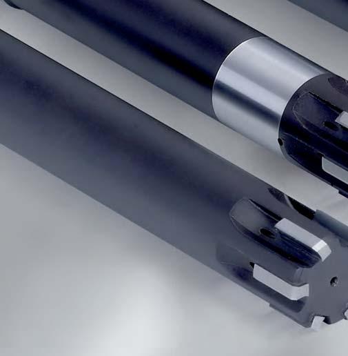
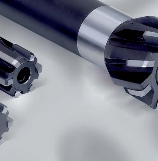
96 96


97 Reaming and Fine Boring Fixed multi-bladed reamers High-performance reamers MonoReam MOR MonoReam With the MonoReam series, MAPAL is setting new standards in fixed reamers. All reamers of the MonoReam series are available as fixed, expandable or finely adjustable versions and, depending on the field of application and material, can be ordered as left-hand fluted or straight fluted versions for through bores and blind holes. Thanks to the different cutting materials, the MonoReam reamers guarantee an exact design, a broad spectrum of applications, the highest MAPAL manufacturing quality and optimum work results. Article overview 100 MonoReam MOR 600 MOR 605 MOR MonoReam MOR 700 MOR 705 MOR MonoReam MOR 800 MOR 805 MOR Cutting data 120 High-performance reamers 97


98 MonoReam With the newly developed multi-bladed reamers in the 600, 700 and 800 series, MAPAL is offering a new, simple, highperformance, standardised reaming system. The reamers in the MonoReam series are available as fixed, expandable or finely adjustable versions and, depending on the application and material, can be ordered as left-hand fluted or straight fluted versions for through bores and blind bores, as well as with different cutting leads and cutting materials. Due to the compatibility between the series, it is possible to change to the optimum system reamer for the specific case if general conditions change in production, for example different quantities or bore tolerances. With a reduced number of variants a large number of possible applications are covered in fine machining with significant rationalisation potential. All tools can be used in common high accuracy chucks such as hydraulic chucks and shrink fit chucks. Advantages: Maximum flexibility thanks to three series with identical dimensions As a result straightforward changing within the MonoReam series Uniform machining results and long tool lives thanks to new adjustment system Straight fluted and left-hand fluted for through bores and blind bores All tools with internal cooling 98


99 Reaming and Fine Boring Fixed multi-bladed reamers High-performance reamers MonoReam MOR The series at a glance Series 800 Setting to the μm can be realised with the reamers in the MonoReam 800 series. Due to a new type of setting system, which is also used on the fineadjustable MAPAL HPR replaceable head reamers, the blades can be finely adjusted. The special three-piece design with screw, pushing ring and adjusting sleeve ensures coaxial errors are compensated and the radial run-out accuracy of the blades after adjustment is within 3 μm. Very tight bore tolerances can be achieved reliably using the exactly set MonoReam 800 series tools. In the case of expensive cutting materials such as PCD or PcBN, significant cost reductions are possible, as the blades can be readjusted to the μm. As a consequence these highperformance cutting materials are optimally utilised. Series 800 Three-piece design with screw, pushing ring and adjusting sleeve Series 700 The MonoReam reamers in the 700 series are used as fixed tools, however this series is optimised for re-grinding to reduce the tool costs. Unlike the MonoReam 800 series, the 700 series is only expanded in diameter by a one-piece expansion screw. The expansion system is therefore suitable for compensation prior to re-grinding and not for setting or readjusting the diameter. Due to the expansion of the diameter it is possible to re-grind all functional surfaces, both on the cutting lead, and also on the tool diameter. As a result, re-ground tools also have the same performance as the original. Series 700 Fixed tool with expansion screw High-performance reamers Series 600 The reamers in the MonoReam 600 series are fixed reamers with brazed blades that cannot be adjusted. They are the simplest of the new MonoReam reamers and are economical to procure. Like all MonoReam reamers, the 600 series is also available as standard in diameters from 7.70 mm to mm and is equipped with four, six or eight blades depending on the diameter. Series 600 Simplest, economical design 99
100 Article overview MonoReam Ordering example Series Type of bore Material Coolant supply Flute helix angle Simplest, economical design FIXED Fixed tool with expansion screw EXPANDABLE Three-piece design with screw, pushing ring and adjusting sleeve FINELY ADJUSTABLE P M K N N P M K Tool data ø l 1 l 3 ød 2 l 2 l 4 z Ordering example SERIES 100 MOR DIAMETER 600. ø MonoReam Type of bore: 0 = Through bore 5 = Blind bore Flute helix angle on the blades: 0 = Straight-fluted 1 = Left-hand fluted Reamer and coolant supply: 6: Fixed reamer 7: Expandable reamer 8: Finely adjustable reamer Bore diameter
101 Reaming and Fine Boring Fixed multi-bladed reamers High-performance reamers MonoReam MOR Tool dimensions* MOR610, 710, 810 MOR605, 705, 805 ød2h6 ød1 MOR600, 700, 800 P l2 l1 l3 l4 * The dimensions stated are identical for all MonoReam series. M K1 K2 K3 N1 N2 High-performance reamers Non-alloy steels, cast-steel, alloy steels Stainless, rust and acid-resistant steels Grey cast iron GG20 30 Spheroidal cast iron GGG40 50 Spheroidal/ vermicular cast iron GGG60 80 Bronze, copper, brass Aluminium R a < 2,0 Ra > 2,0 AlSi other Non-ferrous metals Lead MY1G MY1G Cut HU612 HU612 Lead MY1G MY1G MY1G MY1G MY1G MY1G Cut CU130 HP421 CU130 HP421 CP136 HP421 Lead MU2A MU2A MU2A MU2A MU2A MU2A MU2A MU2A Cut CU130 HP421 CU130 HP421 CP136 HP421 HU612 HU612 FIT CUTTING LEAD [Lead] CUTTING MATERIAL [Cut] H7 M Y 1 G - C P IT or dimensions in μm (example: ) Cutting lead geometry and rake angle: MY1G MU0A Explanation of cutting lead geometry on page 189. Cutting material: HP421 HU612 CP136 CU130 PCD and PcBN on request
102 Reaming and Fine Boring Fixed multi-bladed reamers High-performance reamers MonoReam MOR MonoReam MOR600 Fixed version H7 d 2 h 6 l 4 Cutting material suggestion l 2 l 3 l 1 P M K1 R a <2,0 K1 R a >2,0 K2 K3 N1 N2 S Lead MY1G Cut HU612 Dimensions Specification Order No. ø Tolerance l 1 l 2 l 3 l 4 ø d 2 z 8.00 H MOR600ø8H7MY1G-HU H MOR600ø8.5H7MY1G-HU H MOR600ø9H7MY1G-HU H MOR600ø9.5H7MY1G-HU H MOR600ø10H7MY1G-HU H MOR600ø10.5H7MY1G-HU H MOR600ø11H7MY1G-HU H MOR600ø11.5H7MY1G-HU H MOR600ø12H7MY1G-HU H MOR600ø12.5H7MY1G-HU H MOR600ø13H7MY1G-HU H MOR600ø14H7MY1G-HU H MOR600ø15H7MY1G-HU H MOR600ø16H7MY1G-HU H MOR600ø17H7MY1G-HU H MOR600ø18H7MY1G-HU H MOR600ø19H7MY1G-HU H MOR600ø20H7MY1G-HU H MOR600ø21H7MY1G-HU H MOR600ø22H7MY1G-HU H MOR600ø23H7MY1G-HU H MOR600ø24H7MY1G-HU H MOR600ø25H7MY1G-HU H MOR600ø26H7MY1G-HU H MOR600ø27H7MY1G-HU H MOR600ø28H7MY1G-HU H MOR600ø29H7MY1G-HU H MOR600ø30H7MY1G-HU H MOR600ø31H7MY1G-HU H MOR600ø32H7MY1G-HU H MOR600ø33H7MY1G-HU H MOR600ø34H7MY1G-HU Please order intermediate sizes and tolerances other than H7 using the configuration description at the beginning of chapter MonoReam. 102
103 Reaming and Fine Boring Fixed multi-bladed reamers High-performance reamers MonoReam MOR MonoReam MOR600 Fixed version H7 d 2 h 6 l 4 Cutting material suggestion l 2 l 3 l 1 P M K1 R a <2,0 K1 R a >2,0 K2 K3 N1 N2 S Lead MY1G Cut HU612 Dimensions Specification Order No. ø Tolerance l 1 l 2 l 3 l 4 ø d 2 z H MOR600ø35H7MY1G-HU H MOR600ø36H7MY1G-HU H MOR600ø37H7MY1G-HU H MOR600ø38H7MY1G-HU H MOR600ø39H7MY1G-HU H MOR600ø40H7MY1G-HU Please order intermediate sizes and tolerances other than H7 using the configuration description at the beginning of chapter MonoReam. High-performance reamers 103
104 Reaming and Fine Boring Fixed multi-bladed reamers High-performance reamers MonoReam MOR MonoReam MOR610 Fixed version H7 d 2 h 6 l 4 Cutting material suggestion l 2 l 3 l 1 P M K1 R a <2,0 K1 R a >2,0 K2 K3 N1 N2 S Lead MY1G Cut CU130 HP421 CU130 HP421 CP136 HP421 Dimensions Specification* Order No. ø Tolerance l 1 l 2 l 3 l 4 ø d 2 z HP421 CU130 CP H MOR610ø8H7MY1G-[Cut] H MOR610ø8.5H7MY1G-[Cut] H MOR610ø9H7MY1G-[Cut] H MOR610ø9.5H7MY1G-[Cut] H MOR610ø10H7MY1G-[Cut] H MOR610ø10.5H7MY1G-[Cut] H MOR610ø11H7MY1G-[Cut] H MOR610ø11.5H7MY1G-[Cut] H MOR610ø12H7MY1G-[Cut] H MOR610ø12.5H7MY1G-[Cut] H MOR610ø13H7MY1G-[Cut] H MOR610ø14H7MY1G-[Cut] H MOR610ø15H7MY1G-[Cut] H MOR610ø16H7MY1G-[Cut] H MOR610ø17H7MY1G-[Cut] H MOR610ø18H7MY1G-[Cut] H MOR610ø19H7MY1G-[Cut] H MOR610ø20H7MY1G-[Cut] H MOR610ø21H7MY1G-[Cut] H MOR610ø22H7MY1G-[Cut] H MOR610ø23H7MY1G-[Cut] H MOR610ø24H7MY1G-[Cut] H MOR610ø25H7MY1G-[Cut] H MOR610ø26H7MY1G-[Cut] H MOR610ø27H7MY1G-[Cut] H MOR610ø28H7MY1G-[Cut] H MOR610ø29H7MY1G-[Cut] H MOR610ø30H7MY1G-[Cut] H MOR610ø31H7MY1G-[Cut] H MOR610ø32H7MY1G-[Cut] H MOR610ø33H7MY1G-[Cut] H MOR610ø34H7MY1G-[Cut] *Please complete the specification by indicating the lead desired cutting material [Cut] (see ordering example). 104
105 Reaming and Fine Boring Fixed multi-bladed reamers High-performance reamers MonoReam MOR MonoReam MOR610 Fixed version H7 d 2 h 6 l 4 Cutting material suggestion l 2 l 3 l 1 P M K1 R a <2,0 K1 R a >2,0 K2 K3 N1 N2 S Lead MY1G Cut CU130 HP421 CU130 HP421 CP136 HP421 Dimensions Specification* Order No. ø Tolerance l 1 l 2 l 3 l 4 ø d 2 z HP421 CU130 CP H MOR610ø35H7MY1G-[Cut] H MOR610ø36H7MY1G-[Cut] H MOR610ø37H7MY1G-[Cut] H MOR610ø38H7MY1G-[Cut] H MOR610ø39H7MY1G-[Cut] H MOR610ø40H7MY1G-[Cut] *Please complete the specification by indicating the lead desired cutting material [Cut] (see ordering example). High-performance reamers 105
106 Reaming and Fine Boring Fixed multi-bladed reamers High-performance reamers MonoReam MOR MonoReam MOR605 Fixed version H7 d 2 h 6 Cutting material suggestion l 2 l 3 l 1 l 4 P M K1 R a <2,0 K1 R a >2,0 K2 K3 N1 N2 S Lead MU2A Cut CU130 HP421 CU130 HP421 CP136 HP421 HU612 Dimensions Specification* Order No. ø Tolerance l 1 l 2 l 3 l 4 ø d 2 z HU612 HP421 CU130 CP H MOR605ø8H7MU2A-[Cut] H MOR605ø8.5H7MU2A-[Cut] H MOR605ø9H7MU2A-[Cut] H MOR605ø9.5H7MU2A-[Cut] H MOR605ø10H7MU2A-[Cut] H MOR605ø10.5H7MU2A-[Cut] H MOR605ø11H7MU2A-[Cut] H MOR605ø11.5H7MU2A-[Cut] H MOR605ø12H7MU2A-[Cut] H MOR605ø12.5H7MU2A-[Cut] H MOR605ø13H7MU2A-[Cut] H MOR605ø14H7MU2A-[Cut] H MOR605ø15H7MU2A-[Cut] H MOR605ø16H7MU2A-[Cut] H MOR605ø17H7MU2A-[Cut] H MOR605ø18H7MU2A-[Cut] H MOR605ø19H7MU2A-[Cut] H MOR605ø20H7MU2A-[Cut] H MOR605ø21H7MU2A-[Cut] H MOR605ø22H7MU2A-[Cut] H MOR605ø23H7MU2A-[Cut] H MOR605ø24H7MU2A-[Cut] H MOR605ø25H7MU2A-[Cut] H MOR605ø26H7MU2A-[Cut] H MOR605ø27H7MU2A-[Cut] H MOR605ø28H7MU2A-[Cut] H MOR605ø29H7MU2A-[Cut] H MOR605ø30H7MU2A-[Cut] H MOR605ø31H7MU2A-[Cut] H MOR605ø32H7MU2A-[Cut] H MOR605ø33H7MU2A-[Cut] H MOR605ø34H7MU2A-[Cut] *Please complete the specification by indicating the lead desired cutting material [Cut] (see ordering example). 106
107 Reaming and Fine Boring Fixed multi-bladed reamers High-performance reamers MonoReam MOR MonoReam MOR605 Fixed version H7 d 2 h 6 Cutting material suggestion l 2 l 3 l 4 P M K1 R a <2,0 K1 R a >2,0 K2 K3 N1 N2 S l 1 Lead MU2A Cut CU130 HP421 CU130 HP421 CP136 HP421 HU612 Dimensions Specification* Order No. ø Tolerance l 1 l 2 l 3 l 4 ø d 2 z HU612 HP421 CU130 CP H MOR605ø35H7MU2A-[Cut] H MOR605ø36H7MU2A-[Cut] H MOR605ø37H7MU2A-[Cut] H MOR605ø38H7MU2A-[Cut] H MOR605ø39H7MU2A-[Cut] H MOR605ø40H7MU2A-[Cut] *Please complete the specification by indicating the lead desired cutting material [Cut] (see ordering example). High-performance reamers 107
108 Reaming and Fine Boring Fixed multi-bladed reamers High-performance reamers MonoReam MOR MonoReam MOR700 Expanding version H7 d 2 h 6 Cutting material suggestion l 2 l 3 l 4 P M K1 R a <2,0 K1 R a >2,0 K2 K3 N1 N2 S l 1 Lead MY1G Cut HU612 Dimensions Specification Order No. ø Tolerance l 1 l 2 l 3 l 4 ø d 2 z 8.00 H MOR700ø8H7MY1G-HU H MOR700ø8.5H7MY1G-HU H MOR700ø9H7MY1G-HU H MOR700ø9.5H7MY1G-HU H MOR700ø10H7MY1G-HU H MOR700ø10.5H7MY1G-HU H MOR700ø11H7MY1G-HU H MOR700ø11.5H7MY1G-HU H MOR700ø12H7MY1G-HU H MOR700ø12.5H7MY1G-HU H MOR700ø13H7MY1G-HU H MOR700ø14H7MY1G-HU H MOR700ø15H7MY1G-HU H MOR700ø16H7MY1G-HU H MOR700ø17H7MY1G-HU H MOR700ø18H7MY1G-HU H MOR700ø19H7MY1G-HU H MOR700ø20H7MY1G-HU H MOR700ø21H7MY1G-HU H MOR700ø22H7MY1G-HU H MOR700ø23H7MY1G-HU H MOR700ø24H7MY1G-HU H MOR700ø25H7MY1G-HU H MOR700ø26H7MY1G-HU H MOR700ø27H7MY1G-HU H MOR700ø28H7MY1G-HU H MOR700ø29H7MY1G-HU H MOR700ø30H7MY1G-HU H MOR700ø31H7MY1G-HU H MOR700ø32H7MY1G-HU H MOR700ø33H7MY1G-HU H MOR700ø34H7MY1G-HU Please order intermediate sizes and tolerances other than H7 using the configuration description at the beginning of chapter MonoReam. 108
109 Reaming and Fine Boring Fixed multi-bladed reamers High-performance reamers MonoReam MOR MonoReam MOR700 Expanding version H7 d 2 h 6 Cutting material suggestion l 2 l 3 l 4 P M K1 R a <2,0 K1 R a >2,0 K2 K3 N1 N2 S l 1 Lead MY1G Cut HU612 Dimensions Specification Order No. ø Tolerance l 1 l 2 l 3 l 4 ø d 2 z H MOR700ø35H7MY1G-HU H MOR700ø36H7MY1G-HU H MOR700ø37H7MY1G-HU H MOR700ø38H7MY1G-HU H MOR700ø39H7MY1G-HU H MOR700ø40H7MY1G-HU Please order intermediate sizes and tolerances other than H7 using the configuration description at the beginning of chapter MonoReam. High-performance reamers 109
110 Reaming and Fine Boring Fixed multi-bladed reamers High-performance reamers MonoReam MOR MonoReam MOR710 Expanding version H7 d 2 h 6 Cutting material suggestion l 2 l 3 l 4 P M K1 R a <2,0 K1 R a >2,0 K2 K3 N1 N2 S l 1 Lead MY1G Cut CU130 HP421 CU130 HP421 CP136 HP421 Dimensions Specification* Order No. ø Tolerance l 1 l 2 l 3 l 4 ø d 2 z HP421 CU130 CP H MOR710ø8H7MY1G-[Cut] H MOR710ø8.5H7MY1G-[Cut] H MOR710ø9H7MY1G-[Cut] H MOR710ø9.5H7MY1G-[Cut] H MOR710ø10H7MY1G-[Cut] H MOR710ø10.5H7MY1G-[Cut] H MOR710ø11H7MY1G-[Cut] H MOR710ø11.5H7MY1G-[Cut] H MOR710ø12H7MY1G-[Cut] H MOR710ø12.5H7MY1G-[Cut] H MOR710ø13H7MY1G-[Cut] H MOR710ø14H7MY1G-[Cut] H MOR710ø15H7MY1G-[Cut] H MOR710ø16H7MY1G-[Cut] H MOR710ø17H7MY1G-[Cut] H MOR710ø18H7MY1G-[Cut] H MOR710ø19H7MY1G-[Cut] H MOR710ø20H7MY1G-[Cut] H MOR710ø21H7MY1G-[Cut] H MOR710ø22H7MY1G-[Cut] H MOR710ø23H7MY1G-[Cut] H MOR710ø24H7MY1G-[Cut] H MOR710ø25H7MY1G-[Cut] H MOR710ø26H7MY1G-[Cut] H MOR710ø27H7MY1G-[Cut] H MOR710ø28H7MY1G-[Cut] H MOR710ø29H7MY1G-[Cut] H MOR710ø30H7MY1G-[Cut] H MOR710ø31H7MY1G-[Cut] H MOR710ø32H7MY1G-[Cut] H MOR710ø33H7MY1G-[Cut] *Please complete the specification by indicating the lead desired cutting material [Cut] (see ordering example). 110
111 Reaming and Fine Boring Fixed multi-bladed reamers High-performance reamers MonoReam MOR MonoReam MOR710 Expanding version H7 d 2 h 6 Cutting material suggestion l 2 l 3 l 4 P M K1 R a <2,0 K1 R a >2,0 K2 K3 N1 N2 S l 1 Lead MY1G Cut CU130 HP421 CU130 HP421 CP136 HP421 Dimensions Specification* Order No. ø Tolerance l 1 l 2 l 3 l 4 ø d 2 z HP421 CU130 CP H MOR710ø34H7MY1G-[Cut] H MOR710ø35H7MY1G-[Cut] H MOR710ø36H7MY1G-[Cut] H MOR710ø37H7MY1G-[Cut] H MOR710ø38H7MY1G-[Cut] H MOR710ø39H7MY1G-[Cut] H MOR710ø40H7MY1G-[Cut] *Please complete the specification by indicating the lead desired cutting material [Cut] (see ordering example). High-performance reamers 111
112 Reaming and Fine Boring Fixed multi-bladed reamers High-performance reamers MonoReam MOR MonoReam MOR705 Expanding version H7 d 2 h 6 Cutting material suggestion l 2 l 3 l 1 l 4 P M K1 R a <2,0 K1 R a >2,0 K2 K3 N1 N2 S Lead MU2A Cut CU130 HP421 CU130 HP421 CP136 HP421 HU612 Dimensions Specification* Order No. ø Tolerance l 1 l 2 l 3 l 4 ø d 2 z HU612 HP421 CU130 CP H MOR705ø8H7MU2A-[Cut] H MOR705ø8.5H7MU2A-[Cut] H MOR705ø9H7MU2A-[Cut] H MOR705ø9.5H7MU2A-[Cut] H MOR705ø10H7MU2A-[Cut] H MOR705ø10.5H7MU2A-[Cut] H MOR705ø11H7MU2A-[Cut] H MOR705ø11.5H7MU2A-[Cut] H MOR705ø12H7MU2A-[Cut] H MOR705ø12.5H7MU2A-[Cut] H MOR705ø13H7MU2A-[Cut] H MOR705ø14H7MU2A-[Cut] H MOR705ø15H7MU2A-[Cut] H MOR705ø16H7MU2A-[Cut] H MOR705ø17H7MU2A-[Cut] H MOR705ø18H7MU2A-[Cut] H MOR705ø19H7MU2A-[Cut] H MOR705ø20H7MU2A-[Cut] H MOR705ø21H7MU2A-[Cut] H MOR705ø22H7MU2A-[Cut] H MOR705ø23H7MU2A-[Cut] H MOR705ø24H7MU2A-[Cut] H MOR705ø25H7MU2A-[Cut] H MOR705ø26H7MU2A-[Cut] H MOR705ø27H7MU2A-[Cut] H MOR705ø28H7MU2A-[Cut] H MOR705ø29H7MU2A-[Cut] H MOR705ø30H7MU2A-[Cut] H MOR705ø31H7MU2A-[Cut] H MOR705ø32H7MU2A-[Cut] H MOR705ø33H7MU2A-[Cut] H MOR705ø34H7MU2A-[Cut] *Please complete the specification by indicating the lead desired cutting material [Cut] (see ordering example). 112
113 Reaming and Fine Boring Fixed multi-bladed reamers High-performance reamers MonoReam MOR MonoReam MOR705 Expanding version H7 d 2 h 6 Cutting material suggestion l 2 l 3 l 4 P M K1 R a <2,0 K1 R a >2,0 K2 K3 N1 N2 S l 1 Lead MU2A Cut CU130 HP421 CU130 HP421 CP136 HP421 HU612 Dimensions Specification* Order No. ø Tolerance l 1 l 2 l 3 l 4 ø d 2 z HU612 HP421 CU130 CP H MOR705ø35H7MU2A-[Cut] H MOR705ø36H7MU2A-[Cut] H MOR705ø37H7MU2A-[Cut] H MOR705ø38H7MU2A-[Cut] H MOR705ø39H7MU2A-[Cut] H MOR705ø40H7MU2A-[Cut] *Please complete the specification by indicating the lead desired cutting material [Cut] (see ordering example). High-performance reamers 113
114 Reaming and Fine Boring Fixed multi-bladed reamers High-performance reamers MonoReam MOR MonoReam MOR800 Finely adjustable version H7 d 2 h 6 Cutting material suggestion l 2 l 3 l 4 P M K1 R a <2,0 K1 R a >2,0 K2 K3 N1 N2 S l 1 Lead MY1G Cut HU612 Dimensions Specification Order No. ø Tolerance l 1 l 2 l 3 l 4 ø d 2 z 8.00 H MOR800ø8H7MY1G-HU H MOR800ø8.5H7MY1G-HU H MOR800ø9H7MY1G-HU H MOR800ø9.5H7MY1G-HU H MOR800ø10H7MY1G-HU H MOR800ø10.5H7MY1G-HU H MOR800ø11H7MY1G-HU H MOR800ø11.5H7MY1G-HU H MOR800ø12H7MY1G-HU H MOR800ø12.5H7MY1G-HU H MOR800ø13H7MY1G-HU H MOR800ø14H7MY1G-HU H MOR800ø15H7MY1G-HU H MOR800ø16H7MY1G-HU H MOR800ø17H7MY1G-HU H MOR800ø18H7MY1G-HU H MOR800ø19H7MY1G-HU H MOR800ø20H7MY1G-HU H MOR800ø21H7MY1G-HU H MOR800ø22H7MY1G-HU H MOR800ø23H7MY1G-HU H MOR800ø24H7MY1G-HU H MOR800ø25H7MY1G-HU H MOR800ø26H7MY1G-HU H MOR800ø27H7MY1G-HU H MOR800ø28H7MY1G-HU H MOR800ø29H7MY1G-HU H MOR800ø30H7MY1G-HU H MOR800ø31H7MY1G-HU H MOR800ø32H7MY1G-HU H MOR800ø33H7MY1G-HU H MOR800ø34H7MY1G-HU Please order intermediate sizes and tolerances other than H7 using the configuration description at the beginning of chapter MonoReam. 114
115 Reaming and Fine Boring Fixed multi-bladed reamers High-performance reamers MonoReam MOR MonoReam MOR800 Finely adjustable version H7 d 2 h 6 Cutting material suggestion l 2 l 3 l 4 P M K1 R a <2,0 K1 R a >2,0 K2 K3 N1 N2 S l 1 Lead MY1G Cut HU612 Dimensions Specification Order No. ø Tolerance l 1 l 2 l 3 l 4 ø d 2 z H MOR800ø35H7MY1G-HU H MOR800ø36H7MY1G-HU H MOR800ø37H7MY1G-HU H MOR800ø38H7MY1G-HU H MOR800ø39H7MY1G-HU H MOR800ø40H7MY1G-HU Please order intermediate sizes and tolerances other than H7 using the configuration description at the beginning of chapter MonoReam. High-performance reamers 115
116 Reaming and Fine Boring Fixed multi-bladed reamers High-performance reamers MonoReam MOR MonoReam MOR810 Finely adjustable version H7 d 2 h 6 Cutting material suggestion l 2 l 3 l 4 P M K1 R a <2,0 K1 R a >2,0 K2 K3 N1 N2 S l 1 Lead MY1G Cut CU130 HP421 CU130 HP421 CP136 HP421 Dimensions Specification* Order No. ø Tolerance l 1 l 2 l 3 l 4 ø d 2 z HP421 CU130 CP H MOR810ø8H7MY1G-[Cut] H MOR810ø8.5H7MY1G-[Cut] H MOR810ø9H7MY1G-[Cut] H MOR810ø9.5H7MY1G-[Cut] H MOR810ø10H7MY1G-[Cut] H MOR810ø10.5H7MY1G-[Cut] H MOR810ø11H7MY1G-[Cut] H MOR810ø11.5H7MY1G-[Cut] H MOR810ø12H7MY1G-[Cut] H MOR810ø12.5H7MY1G-[Cut] H MOR810ø13H7MY1G-[Cut] H MOR810ø14H7MY1G-[Cut] H MOR810ø15H7MY1G-[Cut] H MOR810ø16H7MY1G-[Cut] H MOR810ø17H7MY1G-[Cut] H MOR810ø18H7MY1G-[Cut] H MOR810ø19H7MY1G-[Cut] H MOR810ø20H7MY1G-[Cut] H MOR810ø21H7MY1G-[Cut] H MOR810ø22H7MY1G-[Cut] H MOR810ø23H7MY1G-[Cut] H MOR810ø24H7MY1G-[Cut] H MOR810ø25H7MY1G-[Cut] H MOR810ø26H7MY1G-[Cut] H MOR810ø27H7MY1G-[Cut] H MOR810ø28H7MY1G-[Cut] H MOR810ø29H7MY1G-[Cut] H MOR810ø30H7MY1G-[Cut] H MOR810ø31H7MY1G-[Cut] H MOR810ø32H7MY1G-[Cut] H MOR810ø33H7MY1G-[Cut] H MOR810ø34H7MY1G-[Cut] *Please complete the specification by indicating the lead desired cutting material [Cut] (see ordering example). 116
117 Reaming and Fine Boring Fixed multi-bladed reamers High-performance reamers MonoReam MOR MonoReam MOR810 Finely adjustable version H7 d 2 h 6 Cutting material suggestion l 2 l 3 l 4 P M K1 R a <2,0 K1 R a >2,0 K2 K3 N1 N2 S l 1 Lead MY1G Cut CU130 HP421 CU130 HP421 CP136 HP421 Dimensions Specification* Order No. ø Tolerance l 1 l 2 l 3 l 4 ø d 2 z HP421 CU130 CP H MOR810ø35H7MY1G-[Cut] H MOR810ø36H7MY1G-[Cut] H MOR810ø37H7MY1G-[Cut] H MOR810ø38H7MY1G-[Cut] H MOR810ø39H7MY1G-[Cut] H MOR810ø40H7MY1G-[Cut] *Please complete the specification by indicating the lead desired cutting material [Cut] (see ordering example). High-performance reamers 117
118 Reaming and Fine Boring Fixed multi-bladed reamers High-performance reamers MonoReam MOR MonoReam MOR805 Finely adjustable version H7 d 2 h 6 Cutting material suggestion l 2 l 3 l 1 l 4 P M K1 R a <2,0 K1 R a >2,0 K2 K3 N1 N2 S Lead MU2A Cut CU130 HP421 CU130 HP421 CP136 HP421 HU612 Dimensions Specification* Order No. ø Tolerance l 1 l 2 l 3 l 4 ø d 2 z HU612 HP421 CU130 CP H MOR805ø8H7MU2A-[Cut] H MOR805ø8.5H7MU2A-[Cut] H MOR805ø9H7MU2A-[Cut] H MOR805ø9.5H7MU2A-[Cut] H MOR805ø10H7MU2A-[Cut] H MOR805ø10.5H7MU2A-[Cut] H MOR805ø11H7MU2A-[Cut] H MOR805ø11.5H7MU2A-[Cut] H MOR805ø12H7MU2A-[Cut] H MOR805ø12.5H7MU2A-[Cut] H MOR805ø13H7MU2A-[Cut] H MOR805ø14H7MU2A-[Cut] H MOR805ø15H7MU2A-[Cut] H MOR805ø16H7MU2A-[Cut] H MOR805ø17H7MU2A-[Cut] H MOR805ø18H7MU2A-[Cut] H MOR805ø19H7MU2A-[Cut] H MOR805ø20H7MU2A-[Cut] H MOR805ø21H7MU2A-[Cut] H MOR805ø22H7MU2A-[Cut] H MOR805ø23H7MU2A-[Cut] H MOR805ø24H7MU2A-[Cut] H MOR805ø25H7MU2A-[Cut] H MOR805ø26H7MU2A-[Cut] H MOR805ø27H7MU2A-[Cut] H MOR805ø28H7MU2A-[Cut] H MOR805ø29H7MU2A-[Cut] H MOR805ø30H7MU2A-[Cut] H MOR805ø31H7MU2A-[Cut] H MOR805ø32H7MU2A-[Cut] H MOR805ø33H7MU2A-[Cut] H MOR805ø34H7MU2A-[Cut] *Please complete the specification by indicating the lead desired cutting material [Cut] (see ordering example). 118
119 Reaming and Fine Boring Fixed multi-bladed reamers High-performance reamers MonoReam MOR MonoReam MOR805 Finely adjustable version H7 d 2 h 6 Cutting material suggestion l 2 l 3 l 4 P M K1 R a <2,0 K1 R a >2,0 K2 K3 N1 N2 S l 1 Lead MU2A Cut CU130 HP421 CU130 HP421 CP136 HP421 HU612 Dimensions Specification* Order No. ø Tolerance l 1 l 2 l 3 l 4 ø d 2 z HU612 HP421 CU130 CP H MOR805ø35H7MU2A-[Cut] H MOR805ø36H7MU2A-[Cut] H MOR805ø37H7MU2A-[Cut] H MOR805ø38H7MU2A-[Cut] H MOR805ø39H7MU2A-[Cut] H MOR805ø40H7MU2A-[Cut] *Please complete the specification by indicating the lead desired cutting material [Cut] (see ordering example). High-performance reamers 119
120 Reaming and Fine Boring Fixed multi-bladed reamers High-performance reamers MonoReam MOR Cutting data MonoReam MOR Cutting material Material Machining data CU HP HP HP HP CU CP HU HP HP P M K N1 N2 S H Steel, < 700 N/mm² Steel, N/mm² Steel, N/mm² VA < 700 N/mm² VA > 700 N/mm² Grey cast iron (GG) Spheroidal graphite cast iron (bis GGG 50) Spheroidal graphite cast iron (> GGG 50) Cu / Zn / Mg- alloy Plastics soft Plastics heavy Alu-casting alloy (Si < 7%) Alu-casting alloy (Si > 7%) Titanium Hardened materials < 63 HRC ø [mm] v c [m/min] f [mm/u] 0,6-0,8 1,2-1,5 1,2-1,8 2,4-4 allowance a 0,1-0,2 0,2-0,3 0,2-0,3 0,3-0,5 v c [m/min] f [mm/u] 0,6-0,8 1,2-1,5 1,2-1,8 2,4-4 allowance a 0,1-0,2 0,2-0,3 0,2-0,3 0,3-0,5 v c [m/min] f [mm/u] 0,6-0,8 1,2-1,5 1,2-1,8 2,4-4 allowance a 0,1-0,2 0,2-0,3 0,2-0,3 0,3-0,5 v c [m/min] f [mm/u] 0,3-0,5 0,4-0,6 0,5-1,0 1,0-1,5 allowance a 0,1-0,2 0,2-0,3 0,2-0,3 0,3-0,5 v c [m/min] f [mm/u] 0,3-0,5 0,4-0,6 0,5-1,0 1,0-1,5 allowance a 0,1-0,2 0,2-0,3 0,2-0,3 0,3-0,5 v c [m/min] f [mm/u] 0,6-1,2 1,2-1,8 1,2-2,4 2,4-4 allowance a 0,1-0,2 0,2-0,3 0,2-0,3 0,3-0,5 v c [m/min] f [mm/u] 0,6-1,2 1,2-1,8 1,2-2,4 2,4-4 allowance a 0,1-0,2 0,2-0,3 0,2-0,3 0,3-0,5 v c [m/min] f [mm/u] 0,6-1,2 1,2-1,8 1,2-2,4 2,4-4 allowance a 0,1-0,2 0,2-0,3 0,2-0,3 0,3-0,5 v c [m/min] f [mm/u] 0,6-1,2 1,5-2,1 1,5-2,4 2,4-4 allowance a 0,15-0,2 0,2-0,3 0,2-0,3 0,3-0,5 v c [m/min] - f [mm/u] allowance a v c [m/min] - f [mm/u] allowance a v c [m/min] f [mm/u] 0,6-1,2 1,5-2,1 1,5-2,4 2,4-4 allowance a 0,15-0,2 0,2-0,3 0,2-0,3 0,3-0,5 v c [m/min] f [mm/u] 0,6-1,2 1,5-2,1 1,5-2,4 2,4-4 allowance a 0,15-0,2 0,2-0,3 0,2-0,3 0,3-0,5 v c [m/min] f [mm/u] 0,1-0,15 0,15-0,2 0,2-0,3 0,3-0,35 allowance a 0,1-0,2 0,15-0,2 0,15-0,25 0,2-0,3 v c [m/min] 8-12 f [mm/u] 0,1-0,15 0,15-0,2 0,15-0,25 0,2-0,3 allowance a 0,1-0,2 0,15-0,2 0,15-0,25 0,2-0,3 120
121 Reaming and Fine Boring Fixed multi-bladed reamers High-performance reamers MonoReam MOR High-performance reamers 121

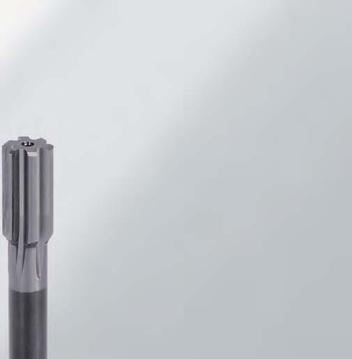

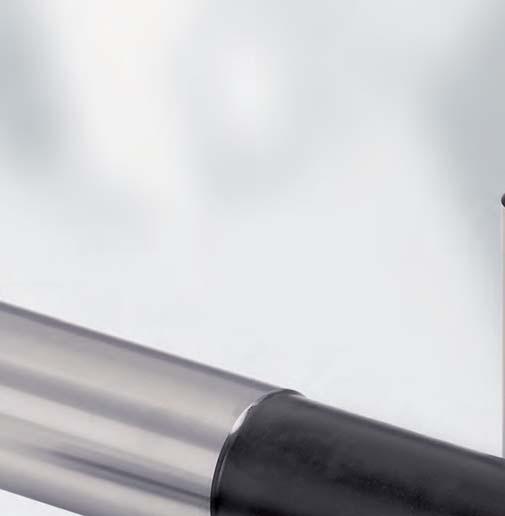
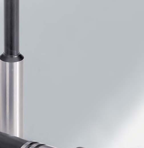
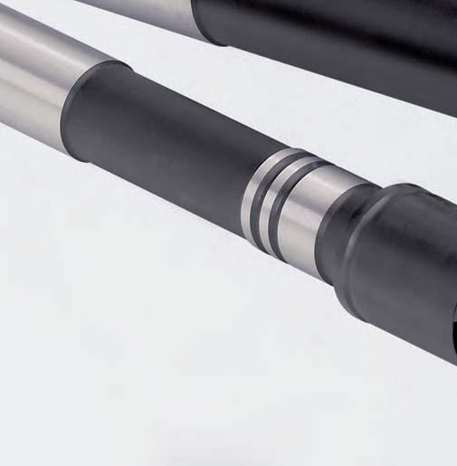
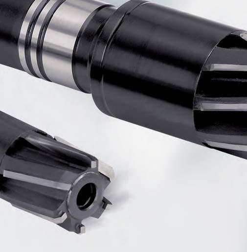
122 122


. It combines the advantages of the solid tool with those of adjustability.")

123 Reaming and Fine Boring Fixed multi-bladed reamers High-performance reamers MonoReam Plus MonoReam Plus High machining values and high process reliability are the crucial demands for a reamer in modern production processes. In order to meet these demands, MAPAL has developed the high-performance reamer. It is characterised by a special coolant feed system in combination with an optimised HPC cutting edge geometry. An additional expansion of the range is the MRP reamer of cermet which is also available as an expandable variant (710). It combines the advantages of the solid tool with those of adjustability. A characteristic feature of this series is the special coolant feed system in combination with an optimised HPC cutting edge geometry. Article overview 124 MonoReam Plus MRP MonoReam Plus MRP MonoReam Plus MRP Cutting data 131 High-performance reamers 123
124 Article overview MonoReam Plus Ordering example Series Type of bore Material Coolant supply Flute helix angle Solid cermet head FIXED Cermet blades FIXED Cermet blades EXPANDABLE P K P K Tool data ø l 1 l 2 l 3 l 4 ø d 2 z ø l 1 l 2 l 3 l 4 ø d 2 z MRP MRP MRP MRP MRP Ordering example SERIES DIAMETER MonoReam Plus MRP 610 ø Flute helix angle on the blades: 0 = Straight-fluted 1 = Left-hand fluted Reamer and coolant supply: 5: fixed reamer, solid cermet head 6: fixed reamer, cermet-blades 7: expandable reamer, cermet-blades Type of bore: 0 = Through bore 5 = Blind bore Bore diameter
125 Reaming and Fine Boring Fixed multi-bladed reamers High-performance reamers MonoReam Plus Tool dimensions MRP510, 610 MRP505, 605 d 2 MRP710 l 2 P l 1 l 3 l 4 M K1 K2 K3 N High-performance reamers Non-alloy steels, cast-steel, alloy steels Stainless, rust and acid-resistant steels Grey cast iron GG20 30 Spheroidal cast iron GGG40 50 Spheroidal/ vermicular cast iron GGG60 80 Aluminium, bronze, copper, brass MRP Lead MV3C MG1M MV3C MG1M Cut CU718 CU718 CU718 CU718 MRP Lead MV3C MG1L MV3C MG1L Cut CU130 CU130 CU130 CU130 MRP710 Lead MG1F MG1F Cut CU130 CU130 FIT CUTTING LEAD [Lead] CUTTING MATERIAL [Cut] H7 M G 1 M - C U IT or dimensions in μm (example: ) Cutting lead geometry and rake angle: MG1M MG1L MV3C MG1F Explanation of cutting lead geometry on page 72/73. Cutting material: CU718 CU
126 Reaming and Fine Boring Fixed multi-bladed reamers High-performance reamers MonoReam Plus MonoReam Plus MRP510 Fixed version, solid cermet head H7 d 2 h 5 l 4 Cutting material suggestion l 2 l 3 l 1 P M K1 K2 K3 N S H Lead MG1M MG1M Cut CU718 CU718 Dimensions Specification Order No. ø Tolerance l 1 l 2 l 3 l 4 ø d 2 z 4.00 H MRP510ø4H7MG1M-CU H MRP510ø4.5H7MG1M-CU H MRP510ø5H7MG1M-CU H MRP510ø5.5H7MG1M-CU H MRP510ø6H7MG1M-CU H MRP510ø6.5H7MG1M-CU H MRP510ø7H7MG1M-CU H MRP510ø7.5H7MG1M-CU H MRP510ø8H7MG1M-CU H MRP510ø8.5H7MG1M-CU H MRP510ø9H7MG1M-CU H MRP510ø9.5H7MG1M-CU H MRP510ø10H7MG1M-CU H MRP510ø10.5H7MG1M-CU H MRP510ø11H7MG1M-CU H MRP510ø11.5H7MG1M-CU H MRP510ø12H7MG1M-CU H MRP510ø13H7MG1M-CU H MRP510ø14H7MG1M-CU H MRP510ø15H7MG1M-CU H MRP510ø16H7MG1M-CU H MRP510ø17H7MG1M-CU H MRP510ø18H7MG1M-CU H MRP510ø19H7MG1M-CU H MRP510ø20H7MG1M-CU Please order intermediate sizes and tolerances other than H7 using the configuration description at the beginning of chapter MRP high-performance reamers. 126
127 Reaming and Fine Boring Fixed multi-bladed reamers High-performance reamers MonoReam Plus MonoReam Plus MRP610 Fixed version, cermet blades H7 Cutting material suggestion d 2 h 5 l 4 l 2 l 1 l 3 P M K1 K2 K3 N S H Lead MG1L MG1L Cut CU130 CU130 Dimensions Specification Order No. ø Tolerance l 1 l 2 l 3 l 4 ø d 2 z H MRP610ø21H7MG1L-CU H MRP610ø22H7MG1L-CU H MRP610ø23H7MG1L-CU H MRP610ø24H7MG1L-CU H MRP610ø25H7MG1L-CU H MRP610ø26H7MG1L-CU H MRP610ø27H7MG1L-CU H MRP610ø28H7MG1L-CU H MRP610ø29H7MG1L-CU H MRP610ø30H7MG1L-CU H MRP610ø31H7MG1L-CU H MRP610ø32H7MG1L-CU H MRP610ø33H7MG1L-CU H MRP610ø34H7MG1L-CU H MRP610ø35H7MG1L-CU H MRP610ø36H7MG1L-CU H MRP610ø37H7MG1L-CU H MRP610ø38H7MG1L-CU H MRP610ø39H7MG1L-CU H MRP610ø40H7MG1L-CU Please order intermediate sizes and tolerances other than H7 using the configuration description at the beginning of chapter MRP high-performance reamers. High-performance reamers 127
128 Reaming and Fine Boring Fixed multi-bladed reamers High-performance reamers MonoReam Plus MonoReam Plus MRP505 Fixed version, solid cermet head H7 Cutting material suggestion d 2 h 5 l 2 l 1 l 3 l 4 P M K1 K2 K3 N S H Lead MV3C MV3C Cut CU718 CU718 Dimensions Specification Order No. ø Tolerance l 1 l 2 l 3 l 4 ø d 2 z 4.00 H MRP505ø4H7MV3C-CU H MRP505ø4.5H7MV3C-CU H MRP505ø5H7MV3C-CU H MRP505ø5.5H7MV3C-CU H MRP505ø6H7MV3C-CU H MRP505ø6.5H7MV3C-CU H MRP505ø7H7MV3C-CU H MRP505ø7.5H7MV3C-CU H MRP505ø8H7MV3C-CU H MRP505ø8.5H7MV3C-CU H MRP505ø9H7MV3C-CU H MRP505ø9.5H7MV3C-CU H MRP505ø10H7MV3C-CU H MRP505ø10.5H7MV3C-CU H MRP505ø11H7MV3C-CU H MRP505ø11.5H7MV3C-CU H MRP505ø12H7MV3C-CU H MRP505ø13H7MV3C-CU H MRP505ø14H7MV3C-CU H MRP505ø15H7MV3C-CU H MRP505ø16H7MV3C-CU H MRP505ø17H7MV3C-CU H MRP505ø18H7MV3C-CU H MRP505ø19H7MV3C-CU H MRP505ø20H7MV3C-CU Please order intermediate sizes and tolerances other than H7 using the configuration description at the beginning of chapter MRP high-performance reamers. 128
129 Reaming and Fine Boring Fixed multi-bladed reamers High-performance reamers MonoReam Plus MonoReam Plus MRP605 Fixed version, cermet blades H7 d 2 h 5 Cutting material suggestion l 4 l 2 l 1 l 3 P M K1 K2 K3 N S H Lead MV3C MV3C Cut CU130 CU130 Dimensions Specification Order No. ø Tolerance l 1 l 2 l 3 l 4 ø d 2 z H MRP605ø21H7MV3C-CU H MRP605ø22H7MV3C-CU H MRP605ø23H7MV3C-CU H MRP605ø24H7MV3C-CU H MRP605ø25H7MV3C-CU H MRP605ø26H7MV3C-CU H MRP605ø27H7MV3C-CU H MRP605ø28H7MV3C-CU H MRP605ø29H7MV3C-CU H MRP605ø30H7MV3C-CU H MRP605ø31H7MV3C-CU H MRP605ø32H7MV3C-CU H MRP605ø33H7MV3C-CU H MRP605ø34H7MV3C-CU H MRP605ø35H7MV3C-CU H MRP605ø36H7MV3C-CU H MRP605ø37H7MV3C-CU H MRP605ø38H7MV3C-CU H MRP605ø39H7MV3C-CU H MRP605ø40H7MV3C-CU Please order intermediate sizes and tolerances other than H7 using the configuration description at the beginning of chapter MRP high-performance reamers. High-performance reamers 129
130 Reaming and Fine Boring Fixed multi-bladed reamers High-performance reamers MonoReam Plus MonoReam Plus MRP710 Expanding version, cermet blades, approx mm expandable H7 Cutting material suggestion d 2 h 5 l 2 l 1 l 3 l 4 P M K1 K2 K3 N S H Lead MG1F MG1F Cut CU130 CU130 Dimensions Specification Order No. ø Tolerance l 1 l 2 l 3 l 4 ø d 2 z 8.00 H MRP710Ø8H7MG1F-CU H MRP710Ø8.5H7MG1F-CU H MRP710Ø9H7MG1F-CU H MRP710Ø9.5H7MG1F-CU H MRP710ø10H7MG1F-CU H MRP710ø10.5H7MG1F-CU H MRP710ø11H7MG1F-CU H MRP710ø11.5H7MG1F-CU H MRP710ø12H7MG1F-CU H MRP710ø12.5H7MG1F-CU H MRP710ø13H7MG1F-CU H MRP710ø14H7MG1F-CU H MRP710ø15H7MG1F-CU H MRP710ø16H7MG1F-CU H MRP710ø17H7MG1F-CU H MRP710ø18H7MG1F-CU H MRP710ø19H7MG1F-CU H MRP710ø20H7MG1F-CU H MRP710ø21H7MG1F-CU H MRP710ø22H7MG1F-CU H MRP710ø23H7MG1F-CU H MRP710ø24H7MG1F-CU H MRP710ø25H7MG1F-CU H MRP710ø26H7MG1F-CU H MRP710ø27H7MG1F-CU H MRP710ø28H7MG1F-CU H MRP710ø29H7MG1F-CU H MRP710ø30H7MG1F-CU H MRP710ø31H7MG1F-CU H MRP710ø32H7MG1F-CU H MRP710ø33H7MG1F-CU H MRP710ø34H7MG1F-CU Please order intermediate sizes and tolerances other than H7 using the configuration description at the beginning of chapter MRP high-performance reamers. 130
131 Reaming and Fine Boring Fixed multi-bladed reamers High-performance reamers MonoReam Plus MonoReam Plus MRP710 Expanding version, cermet blades, approx mm expandable H7 Cutting material suggestion d 2 h 5 l 2 l 1 l 3 l 4 P M K1 K2 K3 N S H Lead MG1F MG1F Cut CU130 CU130 Dimensions Specification Order No. ø Tolerance l 1 l 2 l 3 l 4 ø d 2 z H MRP710ø35H7MG1F-CU H MRP710ø36H7MG1F-CU H MRP710ø37H7MG1F-CU H MRP710ø38H7MG1F-CU H MRP710ø39H7MG1F-CU H MRP710ø40H7MG1F-CU Please order intermediate sizes and tolerances other than H7 using the configuration description at the beginning of chapter MRP high-performance reamers. High-performance reamers Cutting data MonoReam Plus MRP Cutting material Material Machining data CU P K2 Steel, < 700 N/mm² Steel, N/mm² Steel, N/mm² Spheroidal graphite cast iron (bis GGG 50) Spheroidal graphite cast iron (> GGG 50) ø [mm] < v c [m/min] f [mm/u] 0,08-0,12 0,1-0,4 0,3-0,8 0,5-1,0 0,8-1,2 0,8-2,0 allowance a 0,1-0,15 0,15-0,2 0,2-0,3 0,2-0,3 0,2-0,3 0,3-0,5 v c [m/min] f [mm/u] 0,08-0,12 0,1-0,4 0,3-0,8 0,5-1,0 0,8-1,2 0,8-2,0 allowance a 0,1-0,15 0,15-0,2 0,2-0,3 0,2-0,3 0,2-0,3 0,3-0,5 v c [m/min] f [mm/u] 0,08-0,12 0,1-0,3 0,3-0,6 0,3-0,8 0,5-1,0 0,8-1,5 allowance a 0,08-0,12 0,1-0,2 0,2-0,3 0,2-0,3 0,2-0,3 0,3-0,5 v c [m/min] f [mm/u] 0,1-0,15 0,15-0,5 0,3-0,8 0,4-1,2 0,8-1,2 1,0-2,5 allowance a 0,1-0,15 0,15-0,25 0,2-0,3 0,2-0,3 0,2-0,3 0,3-0,5 v c [m/min] f [mm/u] 0,1-0,15 0,15-0,25 0,3-0,8 0,4-1,2 0,8-1,2 1,0-2,5 allowance a 0,1-0,15 0,15-0,25 0,2-0,3 0,2-0,3 0,2-0,3 0,3-0,5 131


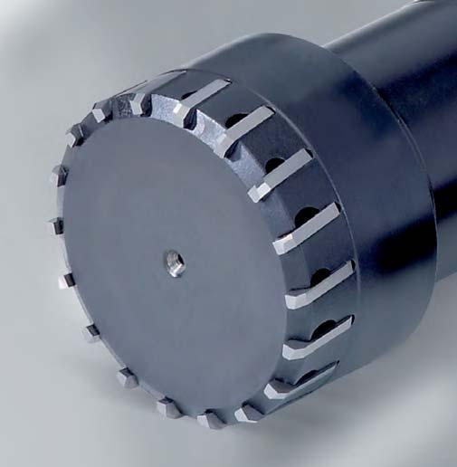
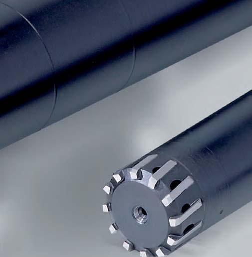
132 132


133 Reaming and Fine Boring Fixed multi-bladed reamers High-performance reamers FeedPlus FPR FeedPlus The most important measure for the performance of multi-bladed reamers is the number of blades. This is limited by the diameter of the tool and by the space required for the chip spaces. Where as to date, for example, there was only space for 8 blades on a 40 mm tool, the FeedPlus now has 16 blades on the same sized tool. Depending on the machining application, a wide range of different cutting materials are employed for these multiple blades. The number of blades and the right choice of cutting material enable machining speeds to be achieved that were previously impossible during reaming. Furthermore, through their support on the bore walls, the large number of blades ensures an outstanding circularity of the reamed bore. The MAPAL standard range includes FPR high-performance reamers of solid carbide and with brazed blades. Article overview 136 FeedPlus FPR FeedPlus FPR Cutting data 142 High-performance reamers 133


134 Reaming and Fine Boring Fixed multi-bladed reamers High-performance reamers FeedPlus FPR FeedPlus with new concept for multi-bladed reamers for more power and higher quality A crucial criterion for the feed rate of multicut reamers is the number of blades. On the newly developed multi-tooth reamer, FeedPlus, MAPAL has created more space for blades with a completely new design principle. As a consequence it is possible, for example, to have ten teeth on a diameter of 14 mm instead of the usual six teeth on conventional reamers. This increase produces several positive effects. The machining time drops drastically, as with a greater number of cutting edges the feed rate can be increased, the tool lives increase and the bore quality, in particular the circularity of the bore, is improved. The higher quality compared with conventional multibladed reamers derives from the large number of arc land chamfers. They are responsible for the guidance of the tool in the bore. The standard programm of FeedPlus reamers incorporates the diameter range 6-40 mm. High benefits thanks to unconventional technology Extremely high feeds thanks to the extreme number of cutting edges Exact circularities Longer tool life thanks to more cutting edges 134
135 Reaming and Fine Boring Fixed multi-bladed reamers High-performance reamers FeedPlus FPR FeedPlus special tools, also as replaceable head system, multi-stage, in combination with guide pads and for the machining of blind holes The special tools from the FeedPlus series allow MAPAL to cover an even broader range of applications. FeedPlus multi-tooth reamers are also available with HFS connection and fine adjustment system for a resource-saving use of the cutting material. Readjustment of the tool diameter to the μm is possible using this system. It is also often possible to extend the tool life in this way. Whereas the MAPAL FeedPlus reamers to date have been particularly suitable for the machining of through bores, the special tools now also enable blind holes to be machined. The HFS replaceable head system allows tool changing on the machine. The solutions tailored to the customers needs make the FeedPlus reamers even more efficient and cost-effective for the demands described. High-performance reamers Taktzeit Time Conventional multi-bladed reamers The higher number of cutting edges of the FeedPlus drastically reduces the machining time, the tool lives are increased and the bore quality improved. Zeitersparnis Time-saving FeedPlus Diameter 135
136 Reaming and Fine Boring Fixed multi-bladed reamers High-performance reamers FeedPlus FPR Article overview FeedPlus high-performance reamers Ordering example Series Type of bore Material Coolant supply Flute helix angle Solid carbide version FIXED Fixed tool with blazed blades FIXED P K 500 P N1 K1 N2 K2 H 610 Tool data ø l 1 l 3 ø d 2 l 2 l 4 z FPR500 FPR Ordering example SERIES DIAMETER 136 FeedPlus FPR 610 ø Type of bore: 0 = Through bore 5 = Blind bore Flute helix angle on the blades: 0 = Straight-fluted 1 = Left-hand fluted Version: 5: Solid carbide, fixed 6: Blazed blades, fixed Bore diameter
137 Reaming and Fine Boring Fixed multi-bladed reamers High-performance reamers FeedPlus FPR Tool dimensions FeedPlus FPR500 d 2 FeedPlus FPR610 l 4 l 2 l 3 l 1 P K1 K2 K3 N1 N2 H High-performance reamers Non-alloy steels, cast-steel, alloy steels Grey cast iron GG20 30 Spheroidal cast iron GGG40 50 Spheroidal/ vermicular cast iron GGG60 80 Bronze, copper, brass Aluminium < HRC 63 Lead Cut Lead Cut FPR500 FPR610 MV0A MV0A MV0A MV0A HP145 HP145 HP145 HP145 MH1E MV3L MM1E MV1E MV1E MQ3Z HP145 FU801 CU718 PU620 HU612 PU620 HU612 FU801 FIT CUTTING LEAD [Lead] CUTTING MATERIAL [Cut] H7 M H 1 E - H P IT or dimensions in μm (example: ) Cutting lead geometry and rake angle: MV1E Explanation of MM1E cutting lead geometry MH1E on page 72/73. MVOA MV3L MQ3Z Cutting material: HP145 CU718 HU612 PU620 FU

138 Reaming and Fine Boring Fixed multi-bladed reamers High-performance reamers FeedPlus FPR Customised special solutions for multi-stage machining and order-specific fitting with guide pads possible. 138
139 Reaming and Fine Boring Fixed multi-bladed reamers High-performance reamers FeedPlus FPR FeedPlus FPR500 Solid carbide H7 d 2 h 6 Cutting material suggestion l 2 l 3 l 1 P M K1 K2 K3 N1 N2 S H Lead MV0A MV0A Cut HP145 HP145 Dimensions Specification Order No. ø Tolerance l 1 l 2 l 3 ø d 2 z 6.00 H FPR500ø6H7MV0A-HP H FPR500ø6.5H7MV0A-HP H FPR500ø7H7MV0A-HP H FPR500ø7.5H7MV0A-HP H FPR500ø8H7MV0A-HP H FPR500ø8.5H7MV0A-HP H FPR500ø9H7MV0A-HP H FPR500ø9.5H7MV0A-HP H FPR500ø10H7MV0A-HP H FPR500ø10.5H7MV0A-HP H FPR500ø11H7MV0A-HP H FPR500ø11.5H7MV0A-HP H FPR500ø12H7MV0A-HP Please order intermediate sizes and tolerances other than H7 using the configuration description at the beginning of chapter FeedPlus. High-performance reamers 139
140 Reaming and Fine Boring Fixed multi-bladed reamers High-performance reamers FeedPlus FPR FeedPlus FPR610 Version with brazed blades H7 d 2 h 6 l 2 l 3 l 4 l 1 Cutting material suggestion P M K1 K2 K3 N1 N2 S H Lead MH1E MV3L MM1E MV1E MQ3Z Cut HP145 FU861 CU718 HU612 PU620 FU801 Dimensions Specification* Order No. ø Tolerance l 1 l 2 l 3 l 4 ø d 2 z MV1E MH1E MM1E MV3L MQ3Z MV1E HU612 HP145 CU718 FU861 FU801 PU H FPR610ø10H7[Lead]-[Cut] H FPR610ø10.5H7[Lead]-[Cut] H FPR610ø11H7[Lead]-[Cut] H FPR610ø11.5H7[Lead]-[Cut] H FPR610ø12H7[Lead]-[Cut] H FPR610ø12.5H7[Lead]-[Cut] H FPR610ø13H7[Lead]-[Cut] H FPR610ø13.5H7[Lead]-[Cut] H FPR610ø14H7[Lead]-[Cut] H FPR610ø14.5H7[Lead]-[Cut] H FPR610ø15H7[Lead]-[Cut] H FPR610ø15.5H7[Lead]-[Cut] H FPR610ø16H7[Lead]-[Cut] H FPR610ø16.5H7[Lead]-[Cut] H FPR610ø17H7[Lead]-[Cut] H FPR610ø17.5H7[Lead]-[Cut] H FPR610ø18H7[Lead]-[Cut] H FPR610ø18.5H7[Lead]-[Cut] H FPR610ø19H7[Lead]-[Cut] H FPR610ø19.5H7[Lead]-[Cut] H FPR610ø20H7[Lead]-[Cut] H FPR610ø20.5H7[Lead]-[Cut] H FPR610ø21H7[Lead]-[Cut] H FPR610ø21.5H7[Lead]-[Cut] H FPR610ø22H7[Lead]-[Cut] H FPR610ø22.5H7[Lead]-[Cut] H FPR610ø23H7[Lead]-[Cut] H FPR610ø23.5H7[Lead]-[Cut] H FPR610ø24H7[Lead]-[Cut] H FPR610ø24.5H7[Lead]-[Cut] H FPR610ø25H7[Lead]-[Cut] H FPR610ø25.5H7[Lead]-[Cut] Please order intermediate sizes and tolerances other than H7 using the configuration description at the beginning of chapter FeedPlus. *Please complete the specification by indicating the lead [Lead] and cutting material [Cut] (see ordering example). 140
141 Reaming and Fine Boring Fixed multi-bladed reamers High-performance reamers FeedPlus FPR FeedPlus FPR610 Version with brazed blades H7 d 2 h 6 Cutting material suggestion l 2 l 3 l 4 l 1 P M K1 K2 K3 N1 N2 S H Lead MH1E MV3L MM1E MV1E MQ3Z Cut HP145 FU861 CU718 HU612 PU620 FU801 Dimensions Specification* Order No. ø Tolerance l 1 l 2 l 3 l 4 ø d 2 z MV1E MH1E MM1E MV3L MQ3Z MV1E HU612 HP145 CU718 FU861 FU801 PU H FPR610ø26H7[Lead]-[Cut] H FPR610ø26.5H7[Lead]-[Cut] H FPR610ø27H7[Lead]-[Cut] H FPR610ø27.5H7[Lead]-[Cut] H FPR610ø28H7[Lead]-[Cut] H FPR610ø28.5H7[Lead]-[Cut] H FPR610ø29H7[Lead]-[Cut] H FPR610ø29.5H7[Lead]-[Cut] H FPR610ø30H7[Lead]-[Cut] H FPR610ø30.5H7[Lead]-[Cut] H FPR610ø31H7[Lead]-[Cut] H FPR610ø31.5H7[Lead]-[Cut] H FPR610ø32H7[Lead]-[Cut] H FPR610ø32.5H7[Lead]-[Cut] H FPR610ø33H7[Lead]-[Cut] H FPR610ø33.5H7[Lead]-[Cut] H FPR610ø34H7[Lead]-[Cut] H FPR610ø34.5H7[Lead]-[Cut] H FPR610ø35H7[Lead]-[Cut] H FPR610ø35.5H7[Lead]-[Cut] H FPR610ø36H7[Lead]-[Cut] H FPR610ø36.5H7[Lead]-[Cut] H FPR610ø37H7[Lead]-[Cut] H FPR610ø37.5H7[Lead]-[Cut] H FPR610ø38H7[Lead]-[Cut] H FPR610ø38.5H7[Lead]-[Cut] H FPR610ø39H7[Lead]-[Cut] H FPR610ø39.5H7[Lead]-[Cut] H FPR610ø40H7[Lead]-[Cut] *Please complete the specification by indicating the lead [Lead] and cutting material [Cut] (see ordering example). High-performance reamers 141
142 Reaming and Fine Boring Fixed multi-bladed reamers High-performance reamers FeedPlus FPR Cutting data FeedPlus FPR Cutting material Material Machining data ø [mm] 10-11,75 11,76-13,75 13,76-17,75 17,76-21,75 21,76-24,75 24,76-30,25 30,26-40 v c [m/min] Steel, < 700 N/mm f = mm/u 0,5-0,8 0,6-1,0 0,8-1,3 1,0-1,5 1,2-1,8 1,3-2 1,44-2,34 allowance a 0,1-0,2 0,1-0,2 0,1-0,3 0,1-0,3 0,1-0,3 0,1-0,3 0,1-0,3 v c [m/min] CU P Steel, N/mm² f [mm/u] 0,5-0,8 0,6-1,0 0,8-1,3 1,0-1,5 1,2-1,8 1,3-2 1,44-2,34 allowance a 0,1-0,2 0,1-0,2 0,1-0,3 0,1-0,3 0,1-0,3 0,1-0,3 0,1-0,3 v c [m/min] Steel, N/mm² f [mm/u] 0,5-0,8 0,6-1,0 0,8-1,3 1,0-1,5 1,2-1,8 1,3-2 1,44-2,34 allowance a 0,1-0,2 0,1-0,2 0,1-0,3 0,1-0,3 0,1-0,3 0,1-0,3 0,1-0,3 v c [m/min] HP M VA/ stainless f [mm/u] 0,4-0,6 0,6-0,8 0,8-1 0,9-1,2 1,1-1,4 1,2-1,6 1,4-1,8 allowance a 0,1 0,15 0,1-0,2 0,1-0,2 0,1-0,3 0,1-0,3 0,1-0,3 v c [m/min] FU Grey cast iron (GG) f [mm/u] 1,2-1,5 1,6-4 2,0-5,0 2,4-6 2,8-7 3,2-8 3,6-9 allowance a 0,1-0,2 0,1-0,2 0,1-0,3 0,1-0,3 0,1-0,3 0,1-0,3 0,1-0,3 HP K Spheroidal graphite cast iron (bis GGG 50) v c [m/min] f [mm/u] 0,9-1,5 1,2-2 1,5-2,5 1,8-3 2,1-3,5 2,4-4 2,7-4,5 allowance a 0,1-0,2 0,1-0,2 0,1-0,3 0,1-0,3 0,1-0,3 0,1-0,3 0,1-0,3 CU Spheroidal graphite cast iron (> GGG 50) v c [m/min] f [mm/u] 0,6-2,4 0,8-3,2 1,0-4,0 1,2-4,8 1,4-5,6 1,6-6,4 1,8-7,2 allowance a 0,1-0,2 0,1-0,2 0,1-0,3 0,1-0,3 0,1-0,3 0,1-0,3 0,1-0,3 v c [m/min] 180 HU N2 Blass / Copper Cu / Zn / Mg-alloy f [mm/u] 0,6-2,4 0,8-3,2 1,0-4,0 1,2-4,8 1,4-5,6 1,6-6,4 1,8-7,2 allowance a 0,1-0,2 0,1-0,2 0,1-0,3 0,1-0,3 0,1-0,3 0,1-0,3 0,1-0,3 v c [m/min] HU N2 Aluminium Si <7 % f [mm/u] 0,5-1,8 0,6-2,4 0,8-3,0 0,9-3,6 1,0-4,2 1,2-4,8 1,35-5,4 allowance a 0,1-0,2 0,1-0,2 0,1-0,3 0,1-0,3 0,1-0,3 0,1-0,3 0,1-0,3 v c [m/min] PU N2 Aluminium Si > 7 % f [mm/u] 0,24-0,6 0,32-0,8 0,4-1,0 0,48-1,2 0,56-1,4 0,64-1,6 0,72-1,8 allowance a 0,1-0,2 0,1-0,2 0,1-0,3 0,1-0,3 0,1-0,3 0,1-0,3 0,1-0,3 v c [m/min] FU H Hardened materials < 63 HRC f [mm/u] 0,12-0,3 0,16-0,4 0,2-0,5 0,24-0,6 0,28-0,7 0,32-0,8 0,36-0,9 allowance a 0,05-0,2 0,05-0,2 0,05-0,2 0,05-0,2 0,05-0,2 0,05-0,2 0,05-0,2 142


143 Reaming and Fine Boring Fixed multi-bladed reamers High-performance reamers FeedPlus FPR High-performance reamers Customised special solutions with HFS connection as replaceable head system and for the machining of blind holes. In addition, the proven expansion system can be integrated into the head. 143
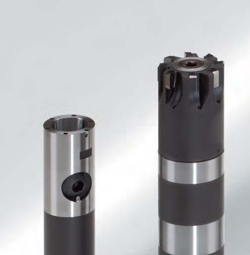

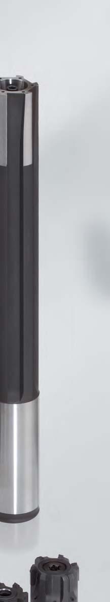
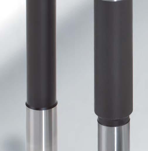
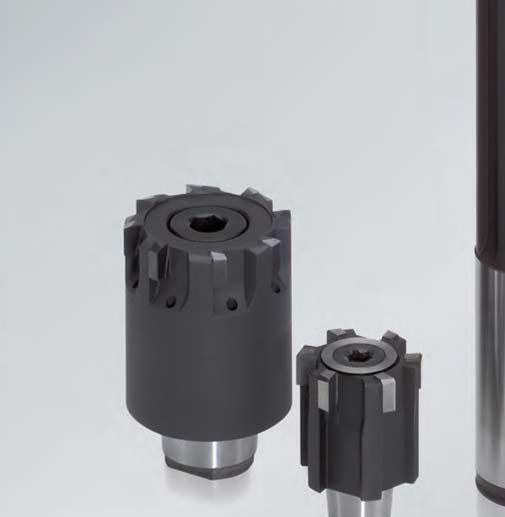
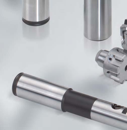
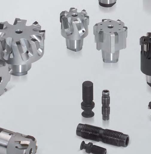
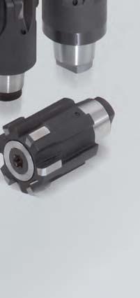
144 144


145 Reaming and Fine Boring Fixed multi-bladed reamers HPR MAPAL High Performance Reamers - The step towards a new generation of tools High Performance Reamers from MAPAL are based on the HFS Head Fitting System. This means that MAPAL offers a complete modern standard series for fixed blade reamers. With its precise tool change and repeatable concentricity and its safe and easy handling, MAPAL s HFS principle is extremely impressive, particularly when mounting and dismantling the tool head. It is in this respect that it stands out from conventional replaceable head systems. The internal coolant supply, enabled by the face contact of the HFS holder and head, releases the coolant straight onto the cutting edges, thus providing it exactly where it is needed. Another important and economic factor is the consistent manufacturing quality which guarantees the same high precision and tool life in every tool head. Because of the constant grinding quality and inherent stability of the whole system, it is possible to incorporate new geometry features, e.g. for chip control. As regrinding is normally no longer necessary with the tool heads, the best possible cutting edge geometry can be developed and applied without having to consider regrinding aspects. In addition to tool heads from 4 mm in diameter and series for through hole and blind holes, the standard programme for MAPAL HPR reamers also includes a comprehensive range of holders with axial or radial clamping system. Article overview 148 HPR replaceable head reamers with configurable parameters 150 Product overview HPR replaceable head reamers 152 HPR replaceable reamers heads, fixed HPR HPR replaceable reamers heads, finely adjustable HPR HFS replaceable head holders 167 Accessories and spares 184 Coolant supply 186 Handling instructions 187 Replaceable head reamers 145


146 MAPAL HFS Head Fitting System The brilliant simple connection for simply brilliant tool concepts The rapid establishment of the HSK clamping system worldwide has provided a technological leap forward in the precision tool industry in issues of stability and concentricity. For tool head connections, however, there are still a large number of different connection systems. With the HFS Head Fitting System MAPAL has now brought a connection for tool heads onto the market which adapts elements of the HSK clamping system to the particular needs of replaceable heads. HFS guarantees high precision and performance with which changeover accuracy and concentricity of less than 3 μm can be The principle features of the HFS connection are: Taper Face connection Positive drive Coolant supply onto the blade reliably achieved in production, setting new standards in economy, user comfort and quality of machining results. Tools with HFS connections are no weaker or less accurate than a monolith tool. On the contrary, a tool with HFS is to some extent superior to a monolith tool since tools with HFS have a higher rigidity than monolith tools because of the extraordinary precision of this type of connection. Despite this the tool head is also produced as a standard part and can therefore be manufactured in larger quantities and with maximum precision. For modern production set-ups the outstanding effect of consistency in performance, including tool life, is achieved to the best possible level with HFS. Universal combination options The design of the MAPAL HFS offers the best possible conditions for the tool to be tailored precisely to specific requirements. This means that the whole tool can be made up of combinations of a variety of materials such as steel or carbide. In designing combination tools the precise concentricity can also be fully utilised and various cutting systems joined together for example a brazed tool with a basic holder for inserts. For tools with large steps between diameters, HFS allows the components of the tool to be produced separately, on suitable production equipment and using the best possible clamping setup for each one. 146


147 Reaming and Fine Boring Fixed multi-bladed reamers HPR MAPAL HFS axial clamping system Taper for easy, highly accurate centring Face connection for rigidity and stability Different holderversions, e. g. cylindrical shank, HSK-A Internal coolant supply, outlet direct onto blade Sturdy, precision clamping screw with differential thread MAPAL HFS radial clamping system: Head change fast, easy and basically on the machine Taper for easy, highly accurate centring Face connection MAPAL HFS holders available with two different clamping systems: Eccentric pin for rapid clamping and release with high clamping force For adaptors with axial clamping the system is applied from the rear through the shank, away from the machine. The tool head is drawn in with a sturdy differential screw, radially aligned to high precision and held in the exact position. Releasing the tool head is also automatic and simple by turning in the reverse direction. Different holder versions, e. g. cylindrical shank, HSK-A Precision pull stud Internal coolant supply, outlet direct onto blade Replaceable head reamers A further significant development in the holder system is radial clamping, which provides clear advantages with regard to tool change times and the amount of handling without any change in precision. The radial clamping system consists of an eccentric pin in the holder and a pull stud fitted on the head. The replaceable head is clamped or released by a quarter turn of the eccentric pin. Changing the heads can be carried out quickly, easily and on the machine. A brief summary of the advantages: Changeover accuracy and concentricity of less than 3 μm Simple, high precision centring with taper High rigidity and stability with optimised vibration damping properties Long tool life and excellent machining results as a result of vibration damping on material Extremely compact, rotationally symmetrical design; suitable for high spindle speeds Simple, direct coolant supply through the connection directly onto the blade, making it particularly suitable for minimal lubrication Modular design allows maximum universal use Easy handling when changing the tool head using clockwise/anticlockwise screw and eccentric. 147
148 Reaming and Fine Boring Fixed multi-bladed reamers HPR Article overview HPR Ordering example HFS l5 l4 HFS l4 l5 Series Type of bore Material Coolant supply Flute helix angle Simplest, economical design FIXED Three-piece design with screw, pushing ring and adjusting sleeve FINELY ADJUSTABLE nitt HPR HPR P Unalloyed steel, strutural-, cast-, free cutting-, case hardened steel, heat treat.-, tool steel, HPR HPR HPR180 HPR 280 HPR HPR150 HPR HPR250 P N K1 K2 P K3 M P M Tool data K N HPR130 HPR100 HPR131 HPR110 HPR180 HPR150 HPR230 HPR200 HPR231 HPR210 HPR280 HPR250 ø d1 l 4 l 5 HFS size No. of teeth z Series HPR130 HPR131 HPR100 HPR110 HPR230 HPR231 HPR200 HPR210 HPR180 HPR150 HPR 280 HPR250 Lead geometry and rake angle Cutting material Lead geometry and rake angle Cutting material Lead and cutting material designation MG: MG1G MC: MC1G MA: MA1G MF: MF1G - Special lead stainless steel ME: ME1G Solid carbide coated: HC412/HC413 Carbide: HU612 Carbide, coated: HP421 Cermet: CU134/CU130 Cermet coated: CP134/ CP136 PVD: PU620 PcBN upon request MG MA: MA1G ML: ML2G MT: Special lead stainless steel Solid carbide coated: HC412/HC413 Carbide: HU612 Carbide, coated: HP421 Cermet: CU134/CU130 Cermet coated: CP134/ CP136 PCB: PU620 PcBN upon request Cutting depth ap [mm] 0,1-0,2 0,1 f z [mm] < ,1-0,2 0,15-0,3 0,1-0,2 0,1 Cutting values v c [m/min] f z [mm] v c [m/min] ,1-0, Ordering example: SERIES DIAMETER HPR 100 C ø High Performance Reamer Type of bore: 0: Straight-fluted to ø 65,00 mm 1: Left-hand fluted to ø 65,00 mm 5: Through bore to ø 65,00 mm 3: Left-hand to ø 18,59 mm 8: Through bore to ø 21,29 mm Version: 1: Fixed reamer 2: Finely adjustable reamer C: Configurable version Length deviates from standard or information to the required grinding tolerance G: Detail tool diameter (Position only used by C and G version) Bore diameter and tool diameter 148
149 Reaming and Fine Boring Fixed multi-bladed reamers HPR HFS HFS HFS HFS l4 l5 l4 l4 l4 HPR HPR HPR110/210 HPR P M K2 K3 N2 K1 K3 N1 H Unalloyed/low alloyed High alloyed steel, steel, temp. tool steel resisting, structural-, heat treat-, nitride-, tool steel Special alloyed steel, Inconel, Hastelloy, Nimonic etc. Stainless/heat resisting steel Grey cast iron GG20-30 Nodular iron pearlitic, malleable iron, GGG60 - GGG80, GTW65, GTS65 - GTS70 Nodular iron pearlitic, malleable iron, GGG60-80 Copper alloy, brass, lead alloyed bronze, lead bronze very good free machining Copper alloy, brass, bronze moderate free machining Copper, Copper alloy, alu-, manganese-, phosphorus bronze hard free machiningr Alu wrought alloy Alu-casting alloy Si-content < 10 %, magnesium alloy Alu-casting alloy Si-content > 10 % Hardend steel, hardened cast iron material, cast iron for chilled castings > < > 600 0,2-0,4 0,1-0,2 0,1-0,25 0,1-0,15 0,1-0,2 0,1-0,2 0,1-0,2 0,06-0,12 0,08-0,12 0,1-0,2 0,1-0, ,1-0,3 0,1-0,3 0,1-0,3 0,15-0,5 0,15-0,5 0,1-0,2 Upon request Upon request > 150 0,2-0,4 0,2-0,4 0,15-0,4 0,1-0,2 0,1 0,15-0,3 0,1-0,3 0,1-0,3 0,1-0,3 0,15-0,5 0,15-0,5 0,1-0,2 Upon request Please ask Please ask Please ask Please ask Upon request Replaceable head reamers > 150 FIT CUTTING LEAD [Lead] CUTTING MATERIAL [Cut] H7MY1G-CP136 IT or dimensions in μm (example: ) Cutting lead form and radial rank: MY1G MG1G MC1G MA0A MA1G MA1N ME1G ML2G MF1G Explanation of cutting lead geometry on page 72/73. Cutting material: HP421 HU612 CP136 CU130 CP134 CU134 HC412 HC413 PU
150 Reaming and Fine Boring Fixed multi-bladed reamers HPR Technical notes HPR replaceable reamer heads with configurable parameters The standard versions of the HPR replaceable reamer heads can be easily adapted individually with configurable parameters. These semi-standard items are based on a standardised design where one or more parameters can be configured. The coding for the different types which can be configured follows the coding for the normal version but is given an additional C (configurable). 1. Configurable parameters for replaceable reamer heads HPR100C, 110C, 150C and 200C, 210C, 250C HPR100C/200C HPR110C/210C C1* C1* For HPR100C, HPR200C, HPR110C, HPR210C, HPR150C and HPR250C versions the ground blade diameter and the grinding dimension for the replaceable reamer head can be selected individually. This means the maximum dimension of the blade diameter is then determined. No adjustment supplement is charged for the configuration which deviates from the standard. Order example for replaceable reamer head HPR110C HPR150C/250C H7 (+ 21 μm) - diameter of bore: ø20 - for use in steel - layout for medium tolerance C1* Order details: HPR110Cø20H7ME1G-CU Configurable parameters for replaceable reamer heads HPR130C, 131C, 180C, 230C, 231C, 280C HPR130C/230C C2** C1* 5 increases by factor 10xd1 5 stays at maximum 150 mm HPR131C/231C C2** C1* For HPR130C, HPR131C, HPR180C, HPR230C, HPR231C and HPR280C versions the ground blade diameter and the grinding dimension can be selected individually. This means that the maximum dimension of the blade diameter is then determined. No adjustment supplement is charged for the configuration which deviates from the standard. In addition the working length can also be configured for these versions, with the exception of solid carbide designs HC412/ HC413. For replaceable heads for working lengths which are modified a supplement is charged depending on quantity. HPR180C/280C C2** C1* Order example for replaceable reamer head HPR131C - diameter of bore: ø16 H7 - for use in steel - configured working length 50 mm (standard 45 mm) Order details: * Diameter C1 = Diameter d1 ** Length C2 = Length l4 and l5 150
151 Reaming and Fine Boring Fixed multi-bladed reamers HPR Technical notes The standard versions of the HFS holders can be easily adapted individually with configurable parameters. These semistandard items are based on a standard holder design where the working length can be configured. The coding for the different types which can be configured follows the coding for the original design but is given an additional C (configurable). Cylindrical shank C2** The working length (l5 and l3 for cylindrical shank holder) given in the individual tables can be configured for all the versions. A supplement is charged for these length modifications. Cylindrical shank HSK-A C2** Order example for HFS holder HFS101RC with radial configured working length 85 mm (standard 75 mm) Order details: HFS101RC HSK-A063-S Working length: 85 mm C2** Module C2** ** Length C2 = Length l3 from tables on pages Replaceable head reamers Advantages: there are difficult machining conditions caused by thin-walled components, difficult materials and the effects of component geometry or clamping. working length for replaceable reamer heads (only HPR130, HPR131, HPR180, HPR230, HPR231, HPR250 and HPR280) or for HFS holders. system is supplied on request which is best suited to the machining task and consists of HPR replaceable reamer head and HFS holder. 151
152 Reaming and Fine Boring Fixed multi-bladed reamers HPR HPR HFS MAPAL HPR product range Allocation of HFS size to machining diameter HFS holders HPR replaceable reamer heads Threaded spindle or pull stud For through holes Cylindrical shank HSK-A HPR131 HPR231 HFS 12 HPR110 HPR210 HSK-C HPR130 HPR230 HFS 12 Module HPR100 HPR200 HPR replaceable reamer heads Threaded spindle or pull stud For blind holes HPR180 HPR280 HFS 12 Cylindrical shank HSK-A HSK-C HPR150 HPR250 Module = Threaded spindle or pull stud without through coolant = Threaded spindle or pull stud with through coolant 152 Note: For HFS holders with radial clamping system, pull studs must be used.
153 Reaming and Fine Boring Fixed multi-bladed reamers HPR HFS 12 HFS 10 HFS 12 HFS 14 HFS 16 HFS 20 HFS 24 HFS 12 HFS 10 HFS 12 HFS 14 HFS 16 HFS 20 HFS HFS 12 Replaceable head reamers HFS 10 HFS 12 HFS 14 HFS 16 HFS 20 HFS
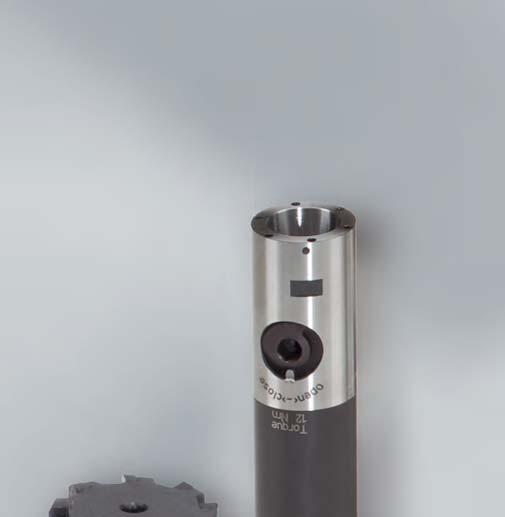
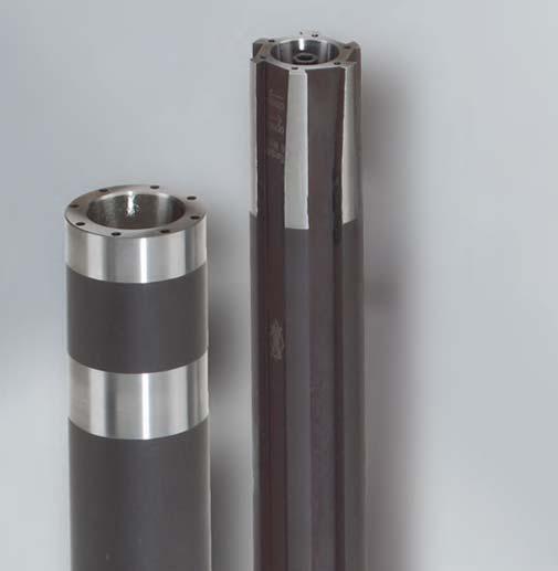

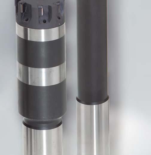
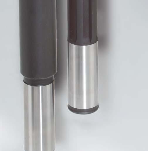
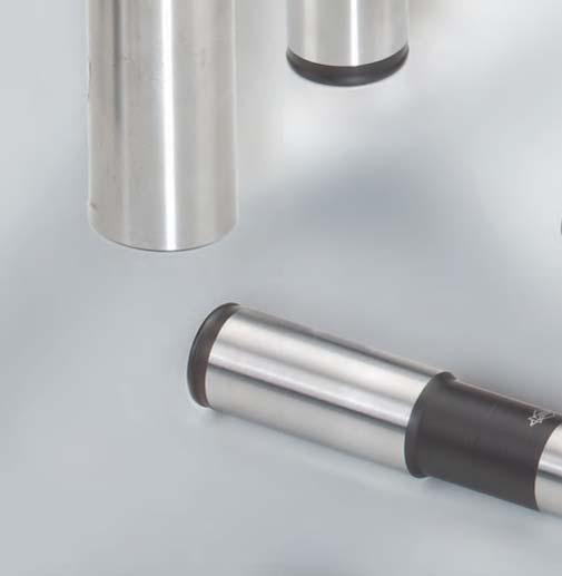
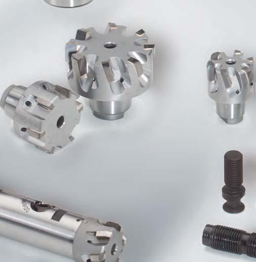
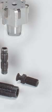
154 154


 and the large quantity of cutting")


155 Reaming and Fine Boring Fixed multi-bladed reamers HPR HPR replaceable version The MAPAL HPR replaceable reamer heads offer run-out and interchangeability accuracy to μm-level through the HFS replaceable head system and thereby the prerequisite for new dimensions in modern high performance machining. With simple construction, direct coolant supply to the cutting edges, which is suitable for minimum quantity lubrication (MQL) and the large quantity of cutting materials available make the MAPAL HPR reamers unique. HPR130 HPR HPR HPR HPR HPR The standard range of MAPAL HPR reamers cover the series of reamers for through and blind bores starting from diameter 7mm. The replaceable head reamers can be fitted with various cutting materials such as carbide and cermet, both coated and uncoated, through to PcBN and PCD. Additionally the HPR replaceable head reamers are available as a finely adjustable version from page 163. Replaceable head reamers 155
156 Reaming and Fine Boring Fixed multi-bladed reamers HPR HPR130 Fixed version HFS HFS l 5 l 4 HFS size l 4 Working length l 5 Cutting edges Carbide Carbide coated Cermet Cermet coated PcBN PCD Solid carbide coated HU612 HP421 CU134/130 CP134/136 Please ask PU620 HC HU612 HP421 CU134/130 CP134/136 Please ask PU620 HC412 HPR131 Fixed version HFS HFS l 4 l 5 HFS size l 4 Working length Cutting edges Carbide Carbide l 5 coated Cermet Cermet coated HU612 HP421 CU134/130 CP134/ HU612 HP421 CU134/130 CP134/136 Specification Order No. Specification Order No H7 HPR131ø10H7ME1G-CU H7 HPR131ø11H7ME1G-CU H7 HPR131ø12H7ME1G-CU H7 HPR131ø13H7ME1G-CU H7 HPR131ø14H7ME1G-CU H7 HPR131ø15H7ME1G-CU H7 HPR131ø16H7ME1G-CU H7 HPR131ø17H7ME1G-CU H7 HPR131ø18H7ME1G-CU
157 Reaming and Fine Boring Fixed multi-bladed reamers HPR HPR180 Fixed version HFS HFS l 5 l 4 HFS size l 4 Working length l 5 Cutting edges Carbide Carbide coated HU612 HP421 CU134/130 CP134/136 Please ask PU620 HC HU612 HP421 CU134/130 CP134/136 Please ask PU620 HC412 Cermet Cermet coated PcBN PCD Solid carbide coated Replaceable head reamers 157
158 Reaming and Fine Boring Fixed multi-bladed reamers HPR HPR100 Fixed version HFS l 4 HFS * HFS l 4 Cutting Carbide Carbide Cermet Cermet PcBN PCD Solid carbide size edges coated coated coated HU612 HP421 CU134/130 CP134/136 PU620 HC HU612 HP421 CU134/130 CP134/136 PU620 HC HU612 HP421 CU134/130 CP134/136 PU620 HC HU612 HP421 CU134/130 CP134/136 PU620 HC HU612 HP421 CU134/130 CP134/136 PU620 HC HU612 HP421 CU134/130 CP134/136 PU620 HC HU612 HP421 CU134/130 CP134/136 PU620 HC412 Please ask Diameter range Specification Order No H7 HPR100ø16H7MC1G-HP H7 HPR100ø18H7MC1G-HP H7 HPR100ø19H7MC1G-HP H7 HPR100ø20H7MC1G-HP H7 HPR100ø22H7MC1G-HP H7 HPR100ø24H7MC1G-HP H7 HPR100ø25H7MC1G-HP H7 HPR100ø26H7MC1G-HP H7 HPR100ø28H7MC1G-HP H7 HPR100ø30H7MC1G-HP H7 HPR100ø32H7MC1G-HP H7 HPR100ø35H7MC1G-HP H7 HPR100ø40H7MC1G-HP H7 HPR100ø45H7MC1G-HP * Diameter range for a specific HFS size. 158
159 Reaming and Fine Boring Fixed multi-bladed reamers HPR HPR110 Fixed version HFS l 4 HFS * HFS size l 4 Cutting edges Carbide Carbide coated Cermet Cermet coated HU612 HP421 CU134/130 CP134/ HU612 HP421 CU134/130 CP134/ HU612 HP421 CU134/130 CP134/ HU612 HP421 CU134/130 CP134/ HU612 HP421 CU134/130 CP134/ HU612 HP421 CU134/130 CP134/ HU612 HP421 CU134/130 CP134/136 Diameter range Specification Order No. Diameter range Specification Order No H7 HPR110ø19H7ME1G-CU H7 HPR110ø32H7ME1G-CU H7 HPR110ø19.05H7ME1G-CU H7 HPR110ø33H7ME1G-CU H7 HPR110ø20H7ME1G-CU H7 HPR110ø34H7ME1G-CU H7 HPR110ø21H7ME1G-CU H7 HPR110ø35H7ME1G-CU H7 HPR110ø22H7ME1G-CU H7 HPR110ø36H7ME1G-CU H7 HPR110ø23H7ME1G-CU H7 HPR110ø37H7ME1G-CU H7 HPR110ø24H7ME1G-CU H7 HPR110ø38H7ME1G-CU H7 HPR110ø25H7ME1G-CU H7 HPR110ø39H7ME1G-CU H7 HPR110ø25.4H7ME1G-CU H7 HPR110ø40H7ME1G-CU H7 HPR110ø26H7ME1G-CU H7 HPR110ø41H7ME1G-CU H7 HPR110ø27H7ME1G-CU H7 HPR110ø42H7ME1G-CU H7 HPR110ø28H7ME1G-CU H7 HPR110ø43H7ME1G-CU H7 HPR110ø29H7ME1G-CU H7 HPR110ø44H7ME1G-CU H7 HPR110ø30H7ME1G-CU H7 HPR110ø45H7ME1G-CU H7 HPR110ø31.75H7ME1G-CU Replaceable head reamers * Diameter range for a specific HFS size. Please state diameter of bore and tolerance when ordering. 159
160 Reaming and Fine Boring Fixed multi-bladed reamers HPR HPR150 Fixed version HFS l 4 HFS * HFS size l 4 Cutting edges Carbide Carbide coated Cermet Cermet coated PcBN PCD Solid carbide coated HU612 HP421 CU134/130 CP134/136 PU620 HC HU612 HP421 CU134/130 CP134/136 PU620 HC HU612 HP421 CU134/130 CP134/136 PU620 HC HU612 HP421 CU134/130 CP134/136 PU620 HC HU612 HP421 CU134/130 CP134/136 PU620 HC HU612 HP421 CU134/130 CP134/136 PU620 HC HU612 HP421 CU134/130 CP134/136 PU620 HC HU612 HP421 CU134/130 CP134/136 PU620 HC HU612 HP421 CU134/130 CP134/136 PU620 HC HU612 HP421 CU134/130 CP134/136 PU620 HC412 Please ask Specification Order No H7 HPR150Ø18H7MV1G-HP H7 HPR150Ø20H7MV1G-HP H7 HPR150Ø22H7MV1G-HP H7 HPR150Ø24H7MV1G-HP H7 HPR150Ø25H7MV1G-HP H7 HPR150Ø26H7MV1G-HP H7 HPR150Ø28H7MV1G-HP H7 HPR150Ø30H7MV1G-HP H7 HPR150Ø32H7MV1G-HP H7 HPR150Ø35H7MV1G-HP H7 HPR150Ø40H7MV1G-HP H7 HPR150Ø45H7MV1G-HP * Diameter range for a specific HFS size. 160


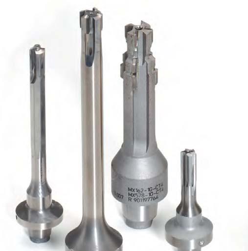

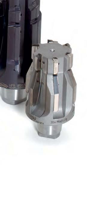


161 Reaming and Fine Boring Fixed multi-bladed reamers HPR Replaceable head reamers 161
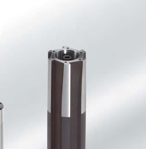

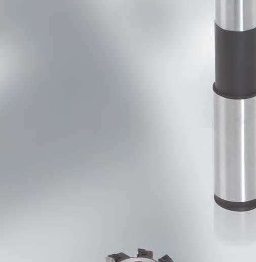
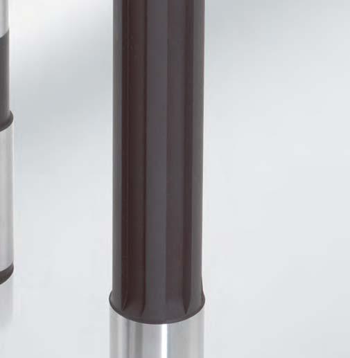
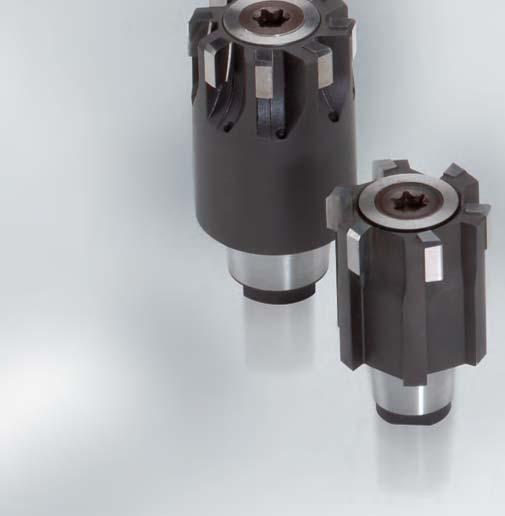
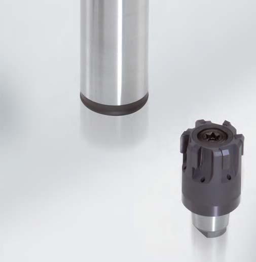
162 162


 as well as a large selection of cutting")


163 Reaming and Fine Boring Fixed multi-bladed reamers HPR finely adjustable HPR replaceable reamer heads Thanks to the new HFS replaceable head system, the MAPAL HPR replaceable head reamers offer radial run-out accuracy and changeover accuracy down to the μm and thus create the preconditions for new dimensions in modern high-performance machining. Straightforward construction, direct coolant supply to the cutting edge and therefore also suitability for minimum quantity lubrication (MQL) as well as a large selection of cutting materials make the MAPAL HPR reamers unique. HPR HPR The blades on the replaceable heads can be set sensitively and with high precision by means of a completely new developed adjusting device. This means bores with extremely tight tolerances can also be reliably machined with multi-flute high performance reamers. In addition, because of the readjustment facility, tool life can be increased many times over, something which brings a significant reduction in costs, particularly with high performance cutting materials like PCD. Replaceable head reamers 163
164 Reaming and Fine Boring Fixed multi-bladed reamers HPR finely adjustable HPR230 Finely adjustable version HFS HFS l 5 l 4 * HU612 HP421 CU134/130 CP134/136 Please ask PU HU612 HP421 CU134/130 CP134/136 Please ask PU620 HFS size l 4 Working length l 5 Cutting edges Carbide Carbide coated Cermet Cermet coated PcBN PCD HPR231 Finely adjustable version HFS HFS l 4 l 5 * HFS size l 4 Working length l 5 Cutting edges Carbide Carbide coated Cermet Cermet coated PcBN PCD HU612 HP421 CU134/130 CP134/136 Please ask PU HU612 HP421 CU134/130 CP134/136 Please ask PU620 * Diameter range for a specific HFS size. Please state diameter of bore and tolerance when ordering. 164
165 Reaming and Fine Boring Fixed multi-bladed reamers HPR finely adjustable HPR280 Finely adjustable version HFS HFS l 5 l 4 * HFS size l 4 Working length l 5 Cutting edges Carbide Carbide coated Cermet Cermet coated PcBN PCD HU612 HP421 CU134/130 CP134/136 Please ask PU HU612 HP421 CU134/130 CP134/136 Please ask PU620 HPR200 Finely adjustable version HFS HFS Replaceable head reamers l 4 * HFS size l 4 Cutting edges Carbide Carbide coated Cermet Cermet coated PcBN PCD HU612 HP421 CU134/130 CP134/136 Please ask PU HU612 HP421 CU134/130 CP134/136 Please ask PU HU612 HP421 CU134/130 CP134/136 Please ask PU HU612 HP421 CU134/130 CP134/136 Please ask PU HU612 HP421 CU134/130 CP134/136 Please ask PU HU612 HP421 CU134/130 CP134/136 Please ask PU620 * Diameter range for a specific HFS size. Please state diameter of bore and tolerance when ordering. 165
166 Reaming and Fine Boring Fixed multi-bladed reamers HPR finely adjustable HPR210 Finely adjustable version HFS HFS l 4 * HFS size l 4 Cutting edges Carbide Carbide coated Cermet Cermet coated PcBN PCD HU612 HP421 CU134/130 CP134/136 Please ask PU HU612 HP421 CU134/130 CP134/136 Please ask PU HU612 HP421 CU134/130 CP134/136 Please ask PU HU612 HP421 CU134/130 CP134/136 Please ask PU HU612 HP421 CU134/130 CP134/136 Please ask PU HU612 HP421 CU134/130 CP134/136 Please ask PU620 HPR250 Finely adjustable version HFS HFS l 4 * HFS size l 4 Cutting edges Carbide Carbide coated Cermet Cermet coated PcBN PCD HU612 HP421 CU134/130 CP134/136 Please ask PU HU612 HP421 CU134/130 CP134/136 Please ask PU HU612 HP421 CU134/130 CP134/136 Please ask PU HU612 HP421 CU134/130 CP134/136 Please ask PU HU612 HP421 CU134/130 CP134/136 Please ask PU HU612 HP421 CU134/130 CP134/136 Please ask PU HU612 HP421 CU134/130 CP134/136 Please ask PU HU612 HP421 CU134/130 CP134/136 Please ask PU HU612 HP421 CU134/130 CP134/136 Please ask PU HU612 HP421 CU134/130 CP134/136 Please ask PU620 * Diameter range for a specific HFS size. Please state diameter of bore and tolerance when ordering. 166


167 Reaming and Fine Boring Fixed multi-bladed reamers HFS replaceable head holders HFS replaceable head holder The MAPAL HFS replaceable head holders are available with two different clamping systems. The axial clamping system is operated from the rear through the shank, and thus from outside the machine. With the radial clamping system, the tool heads can be changed quickly and easily on the machine. Ordering example 168 Choice of lead geometry 170 Axial clamping system 180 Accessories and spare parts 184 Coolant supply 186 Notes on handling 187 Replaceable head reamers 167
168 Reaming and Fine Boring Fixed multi-bladed reamers HFS replaceable head holders HFS replaceable head holder Ordering example HFS 100 R N - 12 A ZYL-HA20 - S HFS Version Version Projection length in mm (rounded) Shank type and Size Material Head Fitting System 10 Through bore 11 Blind hole N Standard design HSK-A063 HSK-C050 S D Steel Densimet C Configured HSK-C063 ZYL-HA16 H Solid carbide Internal cooling Clamping system ZYL-HB16 MOD without IC 1 with IC S R Threaded spindle Radial clamp MOD 080 MOD100 Coding only for blind bores with identical HFS size: A = smaller diameter range B = larger diameter range HFS connection size 10, 12, 14, 16, 20, 24 Ordering example of a HFS replaceable head holder HFS holder with cylindrical shank, internal cooling for through hole, axial clamping, projection length 130, standard design HFS101SN ZYL-HA20-S 168


169 Reaming and Fine Boring Fixed multi-bladed reamers HFS replaceable head holders HFS Head Fitting System HFS holders are available with two different clamping systems: HFS with axial- and radial tool clamping 1 Taper for easy, highly accurate centring 2 Face connection for rigidity and stability 3 Internal coolant supply direct onto blade 4 Different holder versions, e. g. cylindrical shank, HSK-A 5 Sturdy, precision clamping screw with differential thread 6 Precision pull stud 7 Eccentric pin for rapid clamping and release with high clamping force HFS axial clamping system 3 HFS radial clamping system 1 3 For adaptors with axial clamping the system is applied from the rear through the shank, away from the machine. The tool head is drawn in with a sturdy differential screw, radially aligned to high precision and held in the exact position. Releasing the tool head is also automatic and simple by turning in the reverse direction. A further significant development in the holder system is radial clamping, which provides clear advantages with regard to tool change times and the amount of handling without any change in precision. The radial clamping system consists of an eccentric pin in the holder and a pull stud fitted on the head. The replaceable head is clamped or released by a quarter turn of the eccentric pin. Changing the heads can be carried out quickly, easily and on the machine A brief summary of the advantages: Changeover accuracy and concentricity of less than 3 μm Simple, high precision centring with taper High rigidity and stability with optimised vibration damping properties Universal combination options Combination tool with HFS for con-rod machining To be able to construct combination tools in a modular manner, the connection between the sub-tools must be very accurate and have high rigidity. The HFS system developed by MAPAL satisfies these two prerequisites excellently with 3 μm radial run-out and changeover accuracy, as well as due to the face connection. 4 3 Modular design allows maximum universal use Easy handling when changing the tool head using clockwise/ anticlockwise screw and eccentric. 2 1 Boring tool with ISO blades and HFS connection 2 HPR replaceable head reamer with HFS connection 3 Adapter module HFS Adapter HSK-A module 1 The design of the HFS offers the best possible conditions for the tool to be tailored precisely to specific requirements. This means that the whole tool can be made up of combinations of a variety of materials such as steel or carbide. In designing combination tools the precise concentricity can also be fully utilised and various cutting systems joined together for example a brazed tool with a basic holder for inserts. For tools with large steps between diameters, HFS allows the components of the tool to be produced separately, on suitable production equipment and using the best possible clamping setup for each one. Replaceable head reamers 169
170 Reaming and Fine Boring Fixed multi-bladed reamers HFS replaceable head holders HFS replaceable head holder with axial clamping system Shank in accordance with MN 623, similar to DIN 1835-A HFS d 2 h 6 l 2 l 3 l1 Dimensions Specification Order No. HFS size d 2 l 1 l 2 l HFS101SN ZYL-HA20-S HFS101SN ZYL-HA20-S HFS101SN ZYL-HA20-S HFS101SN ZYL-HA25-S HFS101SN ZYL-HA25-S HFS101SN ZYL-HA32-S Dimensions Specification Order No. HFS size d 2 l 1 l 2 l HFS101SN ZYL-HA20-S HFS101SN ZYL-HA20-S HFS101SN ZYL-HA20-S HFS101SN ZYL-HA25-S HFS101SN ZYL-HA25-S HFS101SN ZYL-HA32-S Dimensions Specification Order No. HFS size d 2 l 1 l 2 l HFS101SN ZYL-HA20-S Supply includes: Holder with threaded spindle and hexagon T-key. 170
171 Reaming and Fine Boring Fixed multi-bladed reamers HFS replaceable head holders HFS replaceable head holder with axial clamping system Shank in accordance with MN 623, similar to DIN 1835-A HFS d 2 h6 d 3 l 2 l 1 l 3 l 5 Dimensions Specification Order No. HFS size d 2 d 3 l 1 l 2 l 3 l HFS111SN-10A-110-ZYL-HA20-S HFS111SN-10B-110-ZYL-HA20-S HFS111SN ZYL-HA20-S HFS111SN ZYL-HA25-S HFS111SN-16A-150-ZYL-HA25-S HFS111SN-16B-150-ZYL-HA25-S HFS111SN-20A-150-ZYL-HA25-S HFS111SN-20B-150-ZYL-HA25-S HFS111SN ZYL-HA32-S Dimensions Specification Order No. HFS size d 2 d 3 l 1 l 2 l 3 l 5 Replaceable head reamers HFS111SN-10A-049-ZYL-HA20-S HFS111SN-10B-049-ZYL-HA20-S HFS111SN ZYL-HA20-S HFS111SN ZYL-HA25-S HFS111SN-16A-089-ZYL-HA25-S HFS111SN-16B-089-ZYL-HA25-S HFS111SN-20A-089-ZYL-HA25-S HFS111SN-20B-089-ZYL-HA25-S HFS111SN ZYL-HA32-S Supply includes: Holder with threaded spindle and hexagon T-key. 171
172 Reaming and Fine Boring Fixed multi-bladed reamers HFS replaceable head holders HFS replaceable head holder with axial clamping system with radial and angular alignment Module connection sizes in accordance with MN HFS D l 3 l 2 l 1 Dimensions Specification Order No. HFS size D l 1 l 2 l HFS101SN MOD-060-S HFS101SN MOD-060-S HFS101SN MOD-060-S HFS101SN MOD-060-S HFS101SN MOD-060-S HFS101SN MOD-060-S HFS101SN MOD-080-S Spares for adaptor module Module size D Head Cap Screw* ISO 4762 (DIN 912) Trust Pad* Adjusting Screw* quantity required Order No. Size Order No. Size Order No. Size 60 4 M5x x M8x1x M6x x M8x1x Supply includes: Holder with threaded spindle, hexagon T-key, holding screw for modular adaptor, Parts for angular adjustment of adaptor module. 172
173 Reaming and Fine Boring Fixed multi-bladed reamers HFS replaceable head holders HFS replaceable head holder with axial clamping system with radial and angular alignment Module connection sizes in accordance with MN HFS D l 3 l 2 l 1 Dimensions Specification Order No. HFS size D l 1 l 2 l HFS101SN MOD-060-S HFS101SN MOD-060-S HFS101SN MOD-060-S HFS101SN MOD-060-S HFS101SN MOD-060-S HFS101SN MOD-060-S HFS101SN MOD-080-S Replaceable head reamers Spares for adaptor module Module size D Head Cap Screw* ISO 4762 (DIN 912) Trust Pad* Adjusting Screw* quantity required Order No. Size Order No. Size Order No. Size 60 4 M5x x M8x1x M6x x M8x1x Supply includes: Holder with threaded spindle, hexagon T-key, holding screw for modular adaptor, Parts for angular adjustment of adaptor module. 173
174 Reaming and Fine Boring Fixed multi-bladed reamers HFS replaceable head holders HFS replaceable head holder with axial clamping system with radial and angular alignment Module connection sizes in accordance with MN HFS D d 3 l 3 l 2 l 1 Dimensions Specification Order No. HFS size D d 3 l 1 l 2 l HFS111SN-10A-081-MOD-060-S HFS111SN-10B-081-MOD-060-S HFS111SN MOD-060-S HFS111SN MOD-060-S HFS111SN-16A-121-MOD-060-S HFS111SN-16B-121-MOD-060-S HFS111SN-20A-121-MOD-060-S HFS111SN-20B-121-MOD-060-S HFS111SN MOD-060-S HFS111SN MOD-080-S Spares for adaptor module Modul size D Head Cap Screw* ISO 4762 (DIN 912) Trust Pad* Adjusting Screw* quantity required Order No. Size Order No. Size Order No. Size 60 4 M5x x M8x1x M6x x M8x1x *Quantity required: 4 each Supply includes: Holder with threaded spindle, hexagon T-key, holding screw for modular adaptor, Parts for angular adjustment of adaptor module. 174
175 Reaming and Fine Boring Fixed multi-bladed reamers HFS replaceable head holders HFS replaceable head holder with axial clamping system with radial and angular alignment Module connection sizes in accordance with MN HFS D d 3 l 3 l 2 l 1 Dimensions Specification Order No. HFS size D d 3 l 1 l 2 l HFS111SN-10A-049-MOD-060-S HFS111SN-10B-059-MOD-060-S HFS111SN MOD-060-S HFS111SN MOD-060-S HFS111SN-16A-071-MOD-060-S HFS111SN-16B-071-MOD-060-S HFS111SN-20A-071-MOD-060-S HFS111SN-20B-081-MOD-060-S HFS111SN MOD-060-S HFS111SN MOD-080-S Replaceable head reamers Spares for adaptor module Modul size D Head Cap Screw* ISO 4762 (DIN 912) Trust Pad* Adjusting Screw* quantity required Order No. Size Order No. Size Order No. Size 60 4 M5x x M8x1x M6x x M8x1x *Quantity required: 4 each Supply includes: Holder with threaded spindle, hexagon T-key, holding screw for modular adaptor, Parts for angular adjustment of adaptor module. 175
176 Reaming and Fine Boring Fixed multi-bladed reamers HFS replaceable head holders HFS replaceable head holder with axial clamping system Shank HSK-A in accordance with DIN HFS HSK l 2 l 3 l 1 Long version with HSK-A 63 Dimensions Specification Order No. HFS size l 1 l 2 l 3 HSK-A size HFS101SN HSK-A063-S HFS101SN HSK-A063-S HFS101SN HSK-A063-S HFS101SN HSK-A063-S HFS101SN HSK-A063-S HFS101SN HSK-A063-S Short version with HSK-A 63 Dimensions Specification Order No. HFS size l 1 l 2 l 3 HSK-A size HFS101SN HSK-A063-S HFS101SN HSK-A063-S HFS101SN HSK-A063-S HFS101SN HSK-A063-S HFS101SN HSK-A063-S HFS101SN HSK-A063-S Supply includes: Holder with threaded spindle and hexagon T-key. 176
177 Reaming and Fine Boring Fixed multi-bladed reamers HFS replaceable head holders HFS replaceable head holder with axial clamping system Shank HSK-A in accordance with DIN HFS d 3 HSK l 2 l 3 l 1 Long version with HSK-A 63 Dimensions Specification Order No. HFS size d 3 l 1 l 2 l 3 HSK-A size HFS111SN-10A-117-HSK-A063-S HFS111SN-10B-117-HSK-A063-S HFS111SN HSK-A063-S HFS111SN HSK-A063-S HFS111SN-16A-188-HSK-A063-S HFS111SN-16B-188-HSK-A063-S HFS111SN-20A-188-HSK-A063-S HFS111SN-20B-188-HSK-A063-S HFS111SN HSK-A063-S Short version with HSK-A 63 Dimensions Specification Order No. HFS size d 3 l 1 l 2 l 3 HSK-A size Replaceable head reamers HFS111SN-10A-077-HSK-A063-S HFS111SN-10B-077-HSK-A063-S HFS111SN HSK-A063-S HFS111SN HSK-A063-S HFS111SN-16A-111-HSK-A063-S HFS111SN-16B-111-HSK-A063-S HFS111SN-20A-111-HSK-A063-S HFS111SN-20B-111-HSK-A063-S HFS111SN HSK-A063-S Supply includes: Holder with threaded spindle and hexagon T-key. 177
178 Reaming and Fine Boring Fixed multi-bladed reamers HFS replaceable head holders HFS replaceable head holder with axial clamping system Shank HSK-C in accordance with DIN HFS HSK l 3 l 1 Long version with HSK-C 63 Dimensions Specification Order No. HFS size l 1 l 3 HSK-C size HFS101SN HSK-C063-S HFS101SN HSK-C063-S HFS101SN HSK-C063-S HFS101SN HSK-C063-S HFS101SN HSK-C063-S HFS101SN HSK-C063-S Short version with HSK-C 63 Dimensions Specification Order No. HFS size l 1 l 3 HSK-C size HFS101SN HSK-C063-S HFS101SN HSK-C063-S HFS101SN HSK-C063-S HFS101SN HSK-C063-S HFS101SN HSK-C063-S HFS101SN HSK-C063-S Supply includes: Holder with threaded spindle and hexagon T-key. 178
179 Reaming and Fine Boring Fixed multi-bladed reamers HFS replaceable head holders HFS replaceable head holder with axial clamping system Shank HSK-C in accordance with DIN HFS d 3 HSK l 3 l 1 Long version with HSK-C 63 Dimensions Specification Order No. HFS size d 3 l 1 l 3 HSK-C size HFS111SN-10A-117-HSK-C063-S HFS111SN-10B-117-HSK-C063-S HFS111SN HSK-C063-S HFS111SN HSK-C063-S HFS111SN-16A-188-HSK-C063-S HFS111SN-16B-188-HSK-C063-S HFS111SN-20A-188-HSK-C063-S HFS111SN-20B-188-HSK-C063-S HFS111SN HSK-C063-S Short version with HSK-C 63 Dimensions Specification Order No. HFS size d 3 l 1 l 3 HSK-C size Replaceable head reamers HFS111SN-10A-077-HSK-C063-S HFS111SN-10B-077-HSK-C063-S HFS111SN HSK-C063-S HFS111SN HSK-C063-S HFS111SN-16A-111-HSK-C063-S HFS111SN-16B-111-HSK-C063-S HFS111SN-20A-111-HSK-C063-S HFS111SN-20B-111-HSK-C063-S HFS111SN HSK-C063-S Supply includes: Holder with threaded spindle and hexagon T-key. 179
180 Reaming and Fine Boring Fixed multi-bladed reamers HFS replaceable head holders HFS replaceable head holder with radial clamping system Shank in accordance with MN 623, similar to DIN 1835-A For HPR replaceable reamer head HPR100, HPR110, HPR200, HPR210 HFS d 2 h6 l 2 l 1 l 3 Dimensions Specification Order No. HFS size d 2 h6 l 1 l 2 l HFS101RN ZYL-HA20-S HFS101RN ZYL-HA20-S HFS101RN ZYL-HA25-S HFS101RN ZYL-HA25-S Dimensions Baumaße Specification Spezifikation Bestell-Nr. Order No. HFS Größe size d 2 h6 l 1 l 2 l 3 l 4 18, , , , ,5 HFS101RN ZYL-HA20-S , , , ,5 15,5 HFS101RN ZYL-HA20-S , , HFS101RN ZYL-HA25-S , , HFS101RN ZYL-HA25-S Dimensions Baumaße Specification Spezifikation Bestell-Nr. Order No. HFS Größe size d 2 h6 l 1 l 2 l 3 l HFS101RN ZYL-HA20-S Recommendation: In order to enable a fast change of the reamers with the radial clamping system, at least one additional pull stud should be ordered. Supply includes: Holder with pull stud, hexagon T-key and wrench for pull stud. 180
181 Reaming and Fine Boring Fixed multi-bladed reamers HFS replaceable head holders HFS replaceable head holder with radial clamping system Shank HSK-A in accordance with DIN HFS HSK l 2 l 3 l 1 Long version with HSK-A 63 Dimensions Specification Order No. HFS size l 1 l 2 l 3 HSK-A size HFS101RN HSK-A063-S HFS101RN HSK-A063-S HFS101RN HSK-A063-S HFS101RN HSK-A063-S Short version with HSK-A 63 Dimensions Specification Order No. HFS size l 1 l 2 l 3 HSK-A size HFS101RN HSK-A063-S HFS101RN HSK-A063-S HFS101RN HSK-A063-S HFS101RN HSK-A063-S Replaceable head reamers Recommendation: In order to enable a fast change of the reamers with the radial clamping system, at least one additional pull stud should be ordered. Supply includes: Holder with pull stud, hexagon T-key and wrench for pull stud. 181
182 Reaming and Fine Boring Fixed multi-bladed reamers HFS replaceable head holders HFS replaceable head holder with radial clamping system Shank HSK-C in accordance with DIN HFS HSK l 3 l 1 Long version with HSK-C 63 Dimensions Specification Order No. HFS size l 1 l 3 HSK-C size HFS101RN HSK-C063-S HFS101RN HSK-C063-S HFS101RN HSK-C063-S HFS101RN HSK-C063-S Short version with HSK-C 63 Dimensions Specification Order No. HFS size l 1 l 3 HSK-C size HFS101RN HSK-C063-S HFS101RN HSK-C063-S HFS101RN HSK-C063-S HFS101RN HSK-C063-S Recommendation: In order to enable a fast change of the reamers with the radial clamping system, at least one additional pull stud should be ordered. Supply includes: Holder with pull stud, hexagon T-key and wrench for pull stud. 182
183 Reaming and Fine Boring Fixed multi-bladed reamers HFS replaceable head holders HFS replaceable head holder For HPR replaceable reamer hea20, 121, 130, 131, 180, 230, 231, 280 With axial clamping Dimensions HFS holders Version Specification HFS holders with axial clamping Order No. 12 short with cylindrical shank HFS101SN ZYL-HA20-S extra short with cylindrical shank HFS101SN ZYL-HA20-S long with cylindrical shank HFS101SN ZYL-HA20-S short with module 60 HFS101SN MOD-060-S long with module 60 HFS101SN MOD-060-S short with HSK-A 63 HFS101SN HSK-A063-S long with HSK-A 63 HFS101SN HSK-A063-S short with HSK-C 63 HFS111SN HSK-C063-S long with HSK-C 63 HFS111SN HSK-C063-S Supply includes: Holder with two threaded spindles and hexagon T-key. With radial clamping Dimensions HFS holders Version Specification HFS holders with radial clamping Order No. Replaceable head reamers 12 short with cylindrical shank HFS101RN ZYL-HA20-S extra short with cylindrical shank HFS101RN ZYL-HA20-S long with cylindrical shank HFS101RN ZYL-HA20-S short with module 60 HFS101RN MOD-060-S long with module 60 HFS101RN MOD-060-S short with HSK-A 63 HFS101RN HSK-A063-S long with HSK-A 63 HFS101RN HSK-A063-S short with HSK-C 63 HFS101RN HSK-C063-S long with HSK-C 63 HFS101RN HSK-C063-S Supply includes: Holder with two pull studs and hexagon T-key. Order example of a HFS replaceable head holder HFS-holder with clindrical shank, internal coolant for through bores, tool clamping axial, projection length 130, standard HFS101SN ZYL-HA20-S 183
184 Reaming and Fine Boring Fixed multi-bladed reamers HFS Accessories Accessories and spares for HFS Threaded spindle for axial clamping system Pull stud for radial clamping system HFS size without through coolant threaded spindle MN 618 Order No. with through coolant threaded spindle MN 618 Order No. HFS size without through coolant Order No with through coolant Order No Recommendation: In order to enable a fast change of the reamers with the radial clamping system, at least one additional pull stud should be ordered. Taper cleaner for HFS internal taper short version long version HFS size Size Order No. Size Order No. HFS size Order No. 10 sw2.5 x sw2.5 x sw3 x sw3 x sw3 x sw3 x sw4 x sw4 x sw4 x sw4 x sw5 x sw5 x l 1 D HFS size l 1 D Order No Design: Permissible concentricity deviation for cyl. part to HFS connection 0,002 mm max.
185 Reaming and Fine Boring Fixed multi-bladed reamers HPR Accessories Accessories and spares for HSK-A 63 G S l HSK-A size I S G Order No M18x G HFS size Key width Torque Designation Drive Order No. l l 1 Drive Order No. mm mm Nm fixed with blade blade Nm adjustable- without inserts 1/ insert 1/ Nm adjustable- without inserts 1/ insert 1/ Nm adjustable- without inserts 3/ insert 3/ Nm adjustable- without inserts 3/ insert 3/ Nm adjustable- without inserts 3/ insert 3/ Torque wrench and hexagonal inserts only from HFS size 12 and SW 3 upwards. l D 1 Torque wrench l Key and hexagonal inserts for torque wrench D Replaceable head reamers A Coolant tube Assembly key HSK-A A I G D Order No. HSK-A I D size size M18x Supply includes: Coolant tube with two O rings and locking collar. Design: Easy access angular movement 1 self-centering, axial sealed. Note: Design to DIN Use: For fitting and removing coolant tube. Order No. Use: For closing off threaded hole in HSK tool shanks when no coolant tube is used. Design: With Nylok sleeve to hold plug securely. Material: Stainless steel. 185
186 Reaming and Fine Boring Fixed multi-bladed reamers HPR Technical notes Coolant supply To make full use of the highly effective performance of the HPR reamers, the various series of replaceable heads each need the right coolant supply. The difference in the components lies in the threaded spindle and the pull studs. Depending on the type of head, these are used with coolant through the head or without coolant through the head to ensure direct coolant supply via the connection right onto the blades. Note: For all holders with HFS size 12 two versions are always included in the supply. When assembling care must be taken to select the right system for the replaceable head (see diagram below). Coolant supply without central throughput Reamers must be fitted without central coolant supply. Coolant is passed from the holder onto the replaceable head over the face of the tool. HPR100/200 Clamping screw or HPR110/210 HFS holders Draw pin Coolant supply with central throughput All reamers shown here must be fitted with central coolant throughput. Coolant is supplied centrally and for HPR150 and HPR250 also over the face of the tool. HPR120 HPR121 HPR130/230 Clamping screw or HPR131/231 HFS holders Draw pin HPR180/280 HPR150/

. Tightening 1.")
. 3. Align the markings (see Fig.")
187 Reaming and Fine Boring Fixed multi-bladed reamers HPR Technical notes Notes on handling MAPAL HFS with axial clamping system MAPAL HFS with radial clamping system Fig. 1a Marking Fig. 1b HFS-holder Clamping screw HPR replaceable reamer head HFS-holder Draw pin HPR replaceable reamer head Fig. 2a Markings Fig. 2b Markings Fig. 3a Fig. 4a Fig. 3b Fig. 4b Cleaning Clean all individual parts. Check that the internal and external taper and the surface of the HFS taper are free of foreign bodies (e.g. chips). To clean the internal taper on the HFS holder we recommend the special taper cleaner (see Accessories page 33). Tightening 1. Introduce the end of the threaded spindle without any marking into the HFS holder. Do not screw on! (see Fig. 1a). Centering in the HFS holder is by means of the spigot at the end of the threaded spindle. 2. Place the HPR reamer on the threaded spindle. (see Fig. 2a). 3. Align the markings (see Fig. 2a) on the HPR reamer and the HFS holder: Dot to Dot and hold both parts. Screw the HPR reamer and the HFS holder together with the hexagonal key and tighten firmly. Check that the markings are aligned and the face surface is correct. (see Fig. 3a). Note: HPR 100, 110, 150 are tightened by the reamer. The direction of rotation is in the clockwise direction. HPR 120, 121, 130, 131, 180 are tightened by the holder. The direction of rotation is in the counter clockwise direction. The directions of rotation are indicated on the HFS holder. 5. Recommendation: Tighten the reamer with a torque wrench in clockwise direction. (see Fig. 4a). Recommended clamping torque: The holders are marked with the corresponding clamping torques. Release 1. To release, turn in the opposite direction (see Fig. 4). HFS 10 HFS 12 an4 HFS 16 and 20 HFS 24 Tightening 1. Screw in the pull stud with the threaded side into the reamer. (see Fig. 1b). Attention: Left-handed thread! 2. Introduce the reamer into the holder completely. (see Fig. 2b). In doing so, align the markings on the HPR reamer and the HFS holder: Dot to Dot. 3. Screw the clamp bolt with the hexagonal key in clockwise direction. (see Fig. 3b). The direction of rotation is shown on the holder. Recommendation: Tighten clamp bolt with torque wrench in clockwise direction (see Fig. 4b). Recommended clamping torque: The holders are marked with the corresponding clamping torques. Release HFS 12 an4 HFS 16 and 20 7 Nm 12 Nm 1. To release, turn the holding pin counter clockwise as far as it will go. The reamer will then be ejected. Replaceable head reamers 1. Secure the expandable HPR reamer in the HFS holder. The opposite pairs of blades in the extension at the round marking points on holder and head serve as a reference for measuring and adjusting the tool diameter. 2. Set the desired tool diameter on the precision indicator measuring screw. Then position the precision indicator measuring screw at the reference blades. 3. Place the torx key on the setting screw and slowly turn in the clockwise direction. Set the expandable HPR reamer to the required dimensions. Please notice for expandable HPR reamers: For expandable reamers to ø 30 mm and HFS size only radial clamping is possible. From ø 30 mm and HFS size 24 clamping by threaded spindle is possible. 187
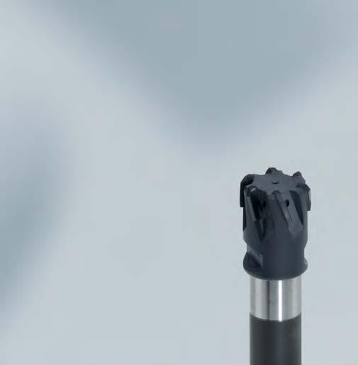
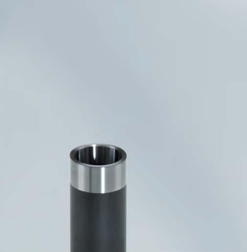

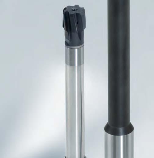
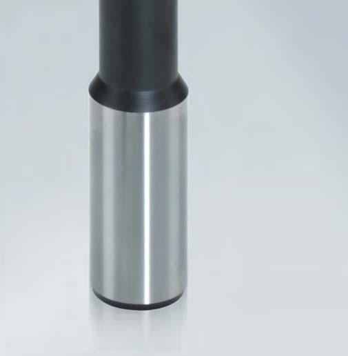
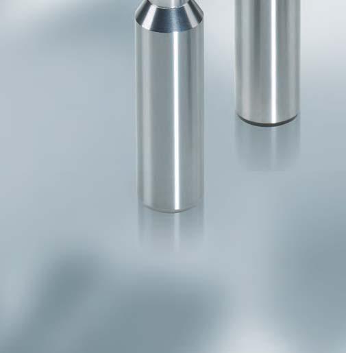
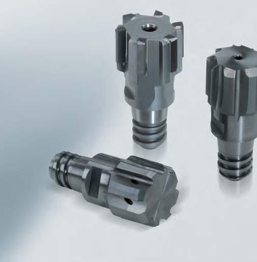

188 188


189 Reaming and Fine Boring Fixed multi-bladed reamers Replaceable head reamers CPReam CPR CPR Complete Performance Reamers high-precision and simple replaceable head system Precision and stability are crucial for a modern, high-performance replaceable head system for reaming. The new CPR replaceable head reamers from MAPAL have been developed precisely to meet these demands. The CFS connection is designed such that the best possible stability and rigidity are achieved by a taper and face connection. The special design and manufacture to the μ of the thread and taperface section guarantee the highly precise radial run-out accuracy of 5 μm. Thanks to the simple and safe handling, the reaming heads can be replaced in the machine tool quickly and easily. The range of CPR replaceable head reamers covers the diameter range from 8 to 40 mm for through bores and blind holes. The heads are available as a solid carbide version and with brazed blades. Carbide and cermet in coated and non-coated versions are available as standard cutting materials. On request, heads can also be produced with PCD or PcBN as cutting material. Article overview 192 CPReam CPR5xx, Solid carbide 194 CPReam CPR CPReam CPR CPReam CPR CFS holder range 201 Accessories 209 Cutting data 210 Replaceable head reamers 189
190 CFS Complete Fitting System highly precise and extremely easy to use connection Increasing carbide prices, higher requirements on process reliability and ease of use the trend toward replaceable head systems is unbroken. For the performance of such tool systems, particularly for reaming, the radial run-out accuracy of the blades and the stability and rigidity of the connection is crucial. It is only with the highest accuracy that all the cutting edges are used equally. This is the prerequisite for the best possible performance, precision and tool life. The new, simple, high precision CFS connection from MAPAL guarantees a radial run-out accuracy below 5 μm. In addition, the replaceable head tools achieve the tool lives of monolithic tools with significantly reduced process costs. The new connection is designed such that a taper and face connection provides the best possible radial run-out accuracy, stability and rigidity. This is achieved by preloading the taper. On tightening fully, the taper on the holder expands slightly and the face surface has perfect contact. The special design and manufacture to the μ of the thread and taper-face section guarantee the highly precise radial run-out accuracy. The advantages at a glance: High rigidity and stability Excellent radial run-out accuracy Simple handling High flexibility 190

191 Reaming and Fine Boring Fixed multi-bladed reamers Replaceable head reamers CPReam CPR Replaceable head reamers 191
192 Article overview CPR Ordering example Series Type of bore Material Coolant supply Version with blazed blades FIXED Solid carbide version FIXED P K M N 605 P K 505 K N 600 P M K 610 P K 510 Tool data ø l 1 sw CFS z size ø l 1 sw CFS z size ø l 1 sw CFS z size CPR CPR CPR510 CPR Bestellbeispiel Ordering example SERIES DIAMETER 192 CPR 600 ø CPReam Type of bore: 0 = Through bore 5 = Blind bore Flute helix angle on the blades: 0 = Straight-fluted 1 = Left-hand fluted Version: 5: Solid carbide 6: Fixed, with blazed blades Bore diameter
193 Reaming and Fine Boring Fixed multi-bladed reamers Replaceable head reamers CPReam CPR Tool dimensions CPR510, 610 CPR505, 605 CPR600 l 1 P M K1 K2 K3 N1 N2 Non-alloy steels, cast-steel, alloy steels Inox, rust and acid-resistant steels Grey cast iron GG20 30 Spheroidal cast iron GGG40 50 Spheroidal/ vermicular cast iron GGG60 80 CPR Lead MV0A MG1M MV0A MG1M MV0A MG1M MV0A MG1M Bronze, copper, brass Aluminium Replaceable head reamers Cut HP145 HP145 HP145 HP145 HP145 HP145 HP145 HP145 CPR Lead MV0A MT0A MV0A MC1G MV0A MC1G MV0A MC1G MA0A MV0A MC0A MC1G MA0A MV0A MC0A MC1G Cut CU130 HP421 HP421 HP421 HP421 CU130 HP421 HP421 HP421 PU620 HU612 PU620 HU612 PU620 HU612 PU620 HU612 CPR610 Lead MY1G MF1G MY1G MY1G MY1G Cut CU130 HP421 HP421 CU130 HP421 FIT CUTTING LEAD [Lead] CUTTING MATERIAL [Cut] H7 M Y 1 G - C P IT or dimensions in μm (example: ) Cutting lead geometry and rake angle: MY1G MV0A MG1M MC1G MA0A MT0A MF1G MC0A Explanation of cutting lead geometry on page 72/73. Cutting material: HP145 HU612 CU130 HP421 PU
194 Reaming and Fine Boring Fixed multi-bladed reamers Replaceable head reamers CPReam CPR CPReam CPR510 Solid carbide H7 Cutting material suggestion P M K1 K2 K3 N1 N2 S H l 1 Lead MG1M MG1M Cut HP145 HP145 Dimensions Specification Order No. ø Tolerance l 1 z CFS size sw 8.00 H CPR510ø8H7MG1M-HP H CPR510ø8.5H7MG1M-HP H CPR510ø9H7MG1M-HP H CPR510ø9.5H7MG1M-HP H CPR510ø10H7MG1M-HP H CPR510ø10.5H7MG1M-HP H CPR510ø11H7MG1M-HP H CPR510ø11.5H7MG1M-HP H CPR510ø12H7MG1M-HP H CPR510ø12.5H7MG1M-HP H CPR510ø13H7MG1M-HP H CPR510ø14H7MG1M-HP H CPR510ø15H7MG1M-HP H CPR510ø16H7MG1M-HP H CPR510ø17H7MG1M-HP H CPR510ø18H7MG1M-HP H CPR510ø19H7MG1M-HP H CPR510ø20H7MG1M-HP H CPR510ø21H7MG1M-HP
195 Reaming and Fine Boring Fixed multi-bladed reamers Replaceable head reamers CPReam CPR CPReam CPR510 Solid carbide H7 Cutting material suggestion l 1 P M K1 K2 K3 N1 N2 S H Lead MG1M MG1M Cut HP145 HP145 Dimensions Specification Order No. ø Tolerance l 1 z CFS size sw H CPR510ø22H7MG1M-HP H CPR510ø23H7MG1M-HP H CPR510ø24H7MG1M-HP H CPR510ø25H7MG1M-HP H CPR510ø26H7MG1M-HP H CPR510ø27H7MG1M-HP H CPR510ø28H7MG1M-HP H CPR510ø29H7MG1M-HP H CPR510ø30H7MG1M-HP H CPR510ø31H7MG1M-HP H CPR510ø32H7MG1M-HP H CPR510ø33H7MG1M-HP H CPR510ø34H7MG1M-HP H CPR510ø35H7MG1M-HP H CPR510ø36H7MG1M-HP H CPR510ø37H7MG1M-HP H CPR510ø38H7MG1M-HP H CPR510ø39H7MG1M-HP H CPR510ø40H7MG1M-HP Replaceable head reamers 195
196 Reaming and Fine Boring Fixed multi-bladed reamers Replaceable head reamers CPReam CPR CPReam CPR505 Solid carbide H7 Cutting material suggestion P M K1 K2 K3 N1 N2 S H l 1 Lead MV0A MV0A Cut HP145 HP145 Dimensions Specification Order No. ø Tolerance l 1 z CFS size sw H CPR505ø10H7MV0A-HP H CPR505ø10.5H7MV0A-HP H CPR505ø11H7MV0A-HP H CPR505ø11.5H7MV0A-HP H CPR505ø12H7MV0A-HP H CPR505ø12.5H7MV0A-HP H CPR505ø13H7MV0A-HP H CPR505ø14H7MV0A-HP H CPR505ø15H7MV0A-HP H CPR505ø16H7MV0A-HP H CPR505ø17H7MV0A-HP H CPR505ø18H7MV0A-HP H CPR505ø19H7MV0A-HP H CPR505ø20H7MV0A-HP H CPR505ø21H7MV0A-HP H CPR505ø22H7MV0A-HP H CPR505ø23H7MV0A-HP
197 Reaming and Fine Boring Fixed multi-bladed reamers Replaceable head reamers CPReam CPR CPReam CPR505 Solid carbide H7 Cutting material suggestion P M K1 K2 K3 N1 N2 S H l 1 Lead MV0A MV0A Cut HP145 HP145 Dimensions Specification Order No. ø Tolerance l 1 z CFS size sw H CPR505ø24H7MV0A-HP H CPR505ø25H7MV0A-HP H CPR505ø26H7MV0A-HP H CPR505ø27H7MV0A-HP H CPR505ø28H7MV0A-HP H CPR505ø29H7MV0A-HP H CPR505ø30H7MV0A-HP H CPR505ø31H7MV0A-HP H CPR505ø32H7MV0A-HP H CPR505ø33H7MV0A-HP H CPR505ø34H7MV0A-HP H CPR505ø35H7MV0A-HP H CPR505ø36H7MV0A-HP H CPR505ø37H7MV0A-HP H CPR505ø38H7MV0A-HP H CPR505ø39H7MV0A-HP H CPR505ø40H7MV0A-HP Replaceable head reamers 197
198 Reaming and Fine Boring Fixed multi-bladed reamers Replaceable head reamers CPReam CPR CPReam CPR600 Version with brazed blades H7 Cutting material suggestion P M K1 K2 K3 N1 N2 S H l 1 Lead MC1G MC0A MC1G Cut HP421 PU620 HU612 Dimensions Specification* Order No. CFS ø Tolerance l 1 z sw size MC1G MC1G MC0A HU612 HP421 PU H CPR600ø8H7[Lead]-[Cut] H CPR600ø10H7[Lead]-[Cut] H CPR600ø12H7[Lead]-[Cut] H CPR600ø14H7[Lead]-[Cut] H CPR600ø16H7[Lead]-[Cut] H CPR600ø18H7[Lead]-[Cut] H CPR600ø20H7[Lead]-[Cut] H CPR600ø22H7[Lead]-[Cut] H CPR600ø24H7[Lead]-[Cut] H CPR600ø25H7[Lead]-[Cut] H CPR600ø26H7[Lead]-[Cut] H CPR600ø28H7[Lead]-[Cut] H CPR600ø30H7[Lead]-[Cut] H CPR600ø32H7[Lead]-[Cut] H CPR600ø34H7[Lead]-[Cut] H CPR600ø36H7[Lead]-[Cut] H CPR600ø38H7[Lead]-[Cut] H CPR600ø40H7[Lead]-[Cut] *Please complete the specification by indicating the lead [Lead] and cutting material [Cut] (see ordering example). 198
199 Reaming and Fine Boring Fixed multi-bladed reamers Replaceable head reamers CPReam CPR CPReam CPR610 Version with brazed blades H7 Cutting material suggestion P M K1 K2 K3 N1 N2 S H l 1 Lead MY1G MF1G MY1G Cut CU130 HP421 HP421 CU130 HP421 Dimensions Specification* Order No. CFS ø Tolerance l 1 z sw size MY1G MY1G MF1G HP421 CU130 HP H CPR610ø8H7[Lead]-[Cut] H CPR610ø10H7[Lead]-[Cut] H CPR610ø12H7[Lead]-[Cut] H CPR610ø14H7[Lead]-[Cut] H CPR610ø16H7[Lead]-[Cut] H CPR610ø18H7[Lead]-[Cut] H CPR610ø20H7[Lead]-[Cut] H CPR610ø22H7[Lead]-[Cut] H CPR610ø24H7[Lead]-[Cut] H CPR610ø25H7[Lead]-[Cut] H CPR610ø26H7[Lead]-[Cut] H CPR610ø28H7[Lead]-[Cut] H CPR610ø30H7[Lead]-[Cut] H CPR610ø32H7[Lead]-[Cut] H CPR610ø34H7[Lead]-[Cut] H CPR610ø36H7[Lead]-[Cut] H CPR610ø38H7[Lead]-[Cut] H CPR610ø40H7[Lead]-[Cut] Replaceable head reamers *Please complete the specification by indicating the lead [Lead] and cutting material [Cut] (see ordering example). 199
200 Reaming and Fine Boring Fixed multi-bladed reamers Replaceable head reamers CPReam CPR CPReam CPR605 Version with brazed blades H7 Cutting material suggestion P M K1 K2 K3 N1 N2 S H l 1 Lead MV0A MT0A MV0A MA0A MV0A Cut CU130 HP421 HP421 HP421 CU130 HP421 PU620 HU612 Dimensions Specification* Order No. CFS ø Tolerance l 1 z sw size MV0A MV0A MV0A MA0A MT0A HP421 HU612 CU130 PU620 HP H CPR605ø14H7[Lead]-[Cut] H CPR605ø16H7[Lead]-[Cut] H CPR605ø18H7[Lead]-[Cut] H CPR605ø20H7[Lead]-[Cut] H CPR605ø22H7[Lead]-[Cut] H CPR605ø24H7[Lead]-[Cut] H CPR605ø25H7[Lead]-[Cut] H CPR605ø26H7[Lead]-[Cut] H CPR605ø28H7[Lead]-[Cut] H CPR605ø30H7[Lead]-[Cut] H CPR605ø32H7[Lead]-[Cut] H CPR605ø34H7[Lead]-[Cut] H CPR605ø36H7[Lead]-[Cut] H CPR605ø38H7[Lead]-[Cut] H CPR605ø40H7[Lead]-[Cut] *Please complete the specification by indicating the lead [Lead] and cutting material [Cut] (see ordering example). For special tolerances and intermediate diameters in the above mentioned ø-ranges also delivery on short notice. 200
201 Reaming and Fine Boring Fixed multi-bladed reamers CFS Replaceable head holders CFS Replaceable head holders CFS 100 N ZYL-HB16 - S Internal coolant: 0 without IC 1 with IC CFS Version Version Projection length in mm (rounded) Shank type and Size Material Complete Fitting System Besides CFS- connection and clamping shank: 10: cylindral version N C Standard design (catalogue item) Configured HSK-A063 HSK-A100 ZYL-HA16 ZYL-HB16 S D H Steel Densimet Solid carbide SK40-A SK40-ADB 20: conical version CFS connection size 06, 08, 10, 12, 14, 16, 20, 24 Replaceable head reamers CPReam replaceable head reamer tightening torques Connection size CFS Tightening torque [Nm]
202 Reaming and Fine Boring Fixed multi-bladed reamers CFS Replaceable head holders CFS Replaceable head holder Steel CFS101 (cylindrical design) with CFS connection, CFS size 6, internal coolant supply d2 h6 d1 l3 l2 l1 Dimensions Specification Order No. Conection size CFS l 1 l 2 l 3 d CFS101N ZYL-HA10-S CFS101N ZYL-HA10-S CFS101N ZYL-HA10-S CFS Replaceable head holder Carbide CFS101 (cylindrical design) with CFS connection, CFS size 6, internal coolant supply d2 h6 d1 l3 l2 l1 Dimensions Specification Order No. Conection size CFS l 1 l 2 l 3 d CFS101N ZYL-HA10-H CFS101N ZYL-HA10-H CFS101N ZYL-HA10-H
203 Reaming and Fine Boring Fixed multi-bladed reamers CFS Replaceable head holders CFS Replaceable head holder Steel CFS101 (cylindrical design) with CFS connection, CFS size 8, internal coolant supply d2 h6 d1 l3 l2 l1 Dimensions Specification Order No. Conection size CFS l 1 l 2 l 3 d CFS101N ZYL-HA12-S CFS101N ZYL-HA12-S CFS101N ZYL-HA12-S CFS Replaceable head holder Carbide CFS101 (cylindrical design) with CFS connection, CFS size 8, internal coolant supply d2 h6 d1 Replaceable head reamers l3 l2 l1 Dimensions Specification Order No. Conection size CFS l 1 l 2 l 3 d CFS101N ZYL-HA12-H CFS101N ZYL-HA12-H CFS101N ZYL-HA12-H
204 Reaming and Fine Boring Fixed multi-bladed reamers CFS Replaceable head holders CFS Replaceable head holder Steel CFS101 (cylindrical design) with CFS connection, CFS size 10, internal coolant supply d2 h6 d1 l3 l1 l2 Dimensions Specification Order No. Conection size CFS l 1 l 2 l 3 d CFS101N ZYL-HA16-S CFS101N ZYL-HA16-S CFS101N ZYL-HA16-S CFS Replaceable head holder Carbide CFS101 (cylindrical design) with CFS connection, CFS size 10, internal coolant supply d2 h6 d1 l3 l1 l2 Dimensions Specification Order No. Conection size CFS l 1 l 2 l 3 d CFS101N ZYL-HA16-H CFS101N ZYL-HA16-H CFS101N ZYL-HA16-H
205 Reaming and Fine Boring Fixed multi-bladed reamers CFS Replaceable head holders CFS Replaceable head holder Steel CFS101 (cylindrical design) with CFS connection, CFS size 12, internal coolant supply d2 h6 d1 l3 l2 l1 Dimensions Specification Order No. Conection size CFS l 1 l 2 l 3 d CFS101N ZYL-HA16-S CFS101N ZYL-HA16-S CFS101N ZYL-HA16-S CFS101N ZYL-HA16-S CFS Replaceable head holder Carbide CFS101 (cylindrical design) with CFS connection, CFS size 12, internal coolant supply d2 h6 d1 Replaceable head reamers l3 l2 l1 Dimensions Specification Order No. Conection size CFS l 1 l 2 l 3 d CFS101N ZYL-HA16-H CFS101N ZYL-HA16-H CFS101N ZYL-HA16-H CFS101N ZYL-HA16-H
206 Reaming and Fine Boring Fixed multi-bladed reamers CFS Replaceable head holders CFS Replaceable head holder Steel CFS101 (cylindrical design) with CFS connection, CFS size 16, internal coolant supply d2 h6 d1 l3 l2 l1 Dimensions Specification Order No. Conection size CFS l 1 l 2 l 3 d CFS101N ZYL-HA25-S CFS101N ZYL-HA25-S CFS101N ZYL-HA25-S CFS101N ZYL-HA25-S CFS Replaceable head holder Carbide CFS101 (cylindrical design) with CFS connection, CFS size 16, internal coolant supply d2 h6 d1 l3 l2 l1 Dimensions Specification Order No. Conection size CFS l 1 l 2 l 3 d CFS101N ZYL-HA25-H CFS101N ZYL-HA25-H CFS101N ZYL-HA25-H CFS101N ZYL-HA25-H
207 Reaming and Fine Boring Fixed multi-bladed reamers CFS Replaceable head holders CFS Replaceable head holder Steel CFS101 (cylindrical design) with CFS connection, CFS size 20, internal coolant supply d2 h6 d1 l3 l2 l1 Dimensions Specification Order No. Conection size CFS l 1 l 2 l 3 d CFS101N ZYL-HA25-S CFS101N ZYL-HA25-S CFS101N ZYL-HA25-S CFS Replaceable head holder Carbide CFS101 (cylindrical design) with CFS connection, CFS size 20, internal coolant supply d2 h6 d1 Replaceable head reamers l3 l2 l1 Dimensions Specification Order No. Conection size CFS l 1 l 2 l 3 d CFS101N ZYL-HA25-H CFS101N ZYL-HA25-H
208 Reaming and Fine Boring Fixed multi-bladed reamers CFS Replaceable head holders CFS Replaceable head holder Steel CFS101 (cylindrical version) for replaceable head tools with CFS connection, CFS size 24, internal cooling supply d2 h6 l 3 l1 l 2 Dimensions Specification Order No. Conection size CFS l 1 l 2 l 3 d CFS101N ZYL-HA32-S CFS101N ZYL-HA32-S CFS101N ZYL-HA32-S CFS Replaceable head holder Carbide CFS101 (cylindrical version) for replaceable head tools with CFS connection, CFS size 24, internal cooling supply d2 h6 l 3 l1 l 2 Dimensions Specification Order No. Conection size CFS l 1 l 2 l 3 d CFS101N ZYL-HA32-H CFS101N ZYL-HA32-H CFS101N ZYL-HA32-H
209 Reaming and Fine Boring Fixed multi-bladed reamers CFS Replaceable head holders CFS Replaceable head holder Steel CFS 101 (cylindrical design) with CFS connection, shank HSK-A in accordance with DIN with internal coolant supply l 2 l 3 l 1 Nominal size HSK-A Conection size CFS Dimensions Specification Order No. l 1 l 2 l CFS101N HSK-A063-S CFS101N HSK-A063-S CFS101N HSK-A063-S CFS101N HSK-A063-S CFS101N HSK-A063-S CFS101N HSK-A063-S Assembly key l1 Replaceable head reamers sw h Conection size CFS Dimensions Order No. sw l1 h
210 Reaming and Fine Boring Fixed multi-bladed reamers CFS Replaceable head holders Cutting data CPReam 5xx Cutting material Material Machining data ø [mm] < v c [m/min] Steel, < 700 N/mm² f [mm/u] 0,6-1,4 0,8-2,2 0,8-2,2 1,0-3,0 HP P Steel, N/mm² allowance a 0,1-0,2 0,2-0,3 0,2-0,3 0,3-0,5 v c [m/min] f [mm/u] 0,6-1,4 0,8-2,2 0,8-2,2 1,0-3,0 allowance a 0,1-0,2 0,2-0,3 0,2-0,3 0,3-0,5 v c [m/min] Steel, N/mm² f [mm/u] 0,6-1,4 0,8-2,2 0,8-2,2 1,0-3,0 allowance a 0,15-0,2 0,2-0,3 0,2-0,3 0,3-0,5 v c [m/min] VA < 700 N/mm² f [mm/u] M allowance a v c [m/min] VA > 700 N/mm² f [mm/u] allowance a v c [m/min] Grey cast iron (GG) f [mm/u] 0,6-1,4 0,8-2,2 0,8-2,2 1,0-3,0 HP K Spheroidal graphite cast iron (bis GGG 50) Spheroidal graphite cast iron (> GGG 50) allowance a 0,15-0,25 0,2-0,3 0,2-0,3 0,3-0,5 v c [m/min] f [mm/u] 0,6-1,4 0,8-2,2 0,8-2,2 1,0-3,0 allowance a 0,15-0,25 0,2-0,3 0,2-0,3 0,3-0,5 v c [m/min] f [mm/u] 0,6-1,4 0,8-2,2 0,8-2,2 1,0-3,0 allowance a 0,15-0,25 0,2-0,3 0,2-0,3 0,3-0,5 v c [m/min] Cu / Zn / Mg- alloy f [mm/u] N Alu-casting alloy (Si < 7%) Alu-casting alloy (Si > 7%) allowance a v c [m/min] f [mm/u] allowance a v c [m/min] f [mm/u] allowance a v c [m/min] Plastics soft f [mm/u] allowance a v c [m/min] Plastics heavy f [mm/u] S H Titanium Hardened materials < 63 HRC allowance a v c [m/min] f [mm/u] allowance a v c [m/min] f [mm/u] allowance a
211 Reaming and Fine Boring Fixed multi-bladed reamers CFS Replaceable head holders Cutting data CPReam 6xx Cutting material Material Machining data ø [mm] < v c [m/min] Steel, < 700 N/mm² f [mm/u] 0,6-0,8 1,2-1,5 1,2-1,8 2,4-4,0 HU* CU P Steel, N/mm² allowance a 0,1-0,2 0,2-0,3 0,2-0,3 0,3-0,5 v c [m/min] f [mm/u] 0,6-0,8 1,2-1,5 1,2-1,8 2,4-4,0 allowance a 0,1-0,2 0,2-0,3 0,2-0,3 0,3-0,5 v c [m/min] Steel, N/mm² f [mm/u] 0,6-0,8 1,2-1,5 1,2-1,8 2,4-4,0 allowance a 0,1-0,2 0,2-0,3 0,2-0,3 0,3-0,5 v c [m/min] VA < 700 N/mm² f [mm/u] 0,3-0,5 0,4-0,6 0,2-0,3 0,5-1,0 HP M allowance a 0,1-0,2 0,2-0,3 0,2-0,3 0,3-0,5 v c [m/min] VA > 700 N/mm² f [mm/u] 0,3-0,5 0,4-0,6 0,2-0,3 0,5-1,0 HP CU* HP* CU HP HU K N1 Grey cast iron (GG) Spheroidal graphite cast iron (bis GGG 50) Spheroidal graphite cast iron (> GGG 50) Cu / Zn / Mg- alloy Plastics soft allowance a 0,1-0,2 0,2-0,3 0,2-0,3 0,3-0,5 v c [m/min] f [mm/u] 0,6-1,2 1,2-1,8 1,2-2,4 2,4-4,0 allowance a 0,1-0,2 0,2-0,3 0,2-0,3 0,3-0,5 v c [m/min] f [mm/u] 0,6-1,2 1,2-1,8 1,2-2,4 2,4-4,0 allowance a 0,1-0,2 0,2-0,3 0,2-0,3 0,3-0,5 v c [m/min] f [mm/u] 0,6-1,4 0,8-2,2 0,8-2,2 1,0-3,0 allowance a 0,15-0,25 0,2-0,3 0,2-0,3 0,3-0,5 v c [m/min] f [mm/u] 0,6-1,2 1,5-2,1 1,5-2,4 2,4-4,0 allowance a 0,15-0,2 0,2-0,3 0,2-0,3 0,3-0,5 v c [m/min] f [mm/u] allowance a v c [m/min] Replaceable head reamers Plastics heavy f [mm/u] HU PU N2 S H Alu-casting alloy (Si < 7%) Alu-casting alloy (Si > 7%) Titanium Hardened materials < 63 HRC allowance a v c [m/min] f [mm/u] 0,6-1,2 1,5-2,1 1,5-2,4 2,4-4,0 allowance a 0,15-0,2 0,2-0,3 0,2-0,3 0,3-0,5 v c [m/min] < 150 f [mm/u] 0,6-1,2 1,5-2,1 1,5-2,4 2,4-4,0 allowance a 0,15-0,2 0,2-0,3 0,2-0,3 0,3-0,5 v c [m/min] f [mm/u] allowance a v c [m/min] f [mm/u] allowance a * Cutting data for cutting materials upon request. 211


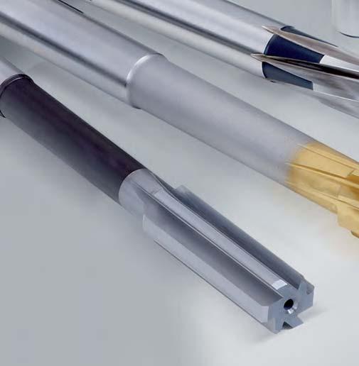
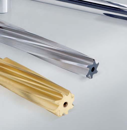

212 212


.")


213 Reaming and Fine Boring Fixed multi-bladed reamers Machine reamers Machine reamers A suitable MAPAL reamer is available even when there is no coolant supply. The NC Series cover the diameter range from 0.98 to 20 mm. Particularly for small and medium-sized production lots, these reamers offer an inexpensive alternative to the high-performance reamers with internal cooling. In addition to the DIN reamers, MAPAL also offers a range which is based on DIN (sdin). Thanks to their straight shank diameter, these tools can be mounted directly in hydraulic or shrink chucks. The tools are mostly available from stock or can be delivered in intermediate dimensions at short notice. Article overview 214 Carbide machine reamers 216 Machine reamers of HSS-E 239 Hand reamers 271 Taper reamers 284 Cutting data 286 Machine reamers 213
214 Carbide machine reamers STANDARD SHAPE DESIGN Similar DIN 8093 A Similar DIN 8093 B NC reamers, straight fluted NC reamers, spiral fluted CUTTING MATERIAL Solid carbide Solid carbide head Solid carbide Solid carbide head Carbide tipped ø-range SPECIFICATION PAGE MSR A 216 MSR B MSR B MSR B 217/ Similar DIN 8093 B Micro NC reamers, spiral fluted Solid carbide MSR510G-8093B 220 Similar DIN 8093 B NC reamers, spiral fluted with 0,01 mm increments Solid carbide DIN 8093 A Straight fluted Solid carbide Solid carbide head Carbide tipped MSR510G-8093B MSR510G-8093B MDR A MDR A MDR A / DIN 8093 B Spiral fluted Solid carbide Solid carbide head MDR B MDR B DIN 8093 B Angulare fluted Carbide tippe MDR B DIN 8094 A Straight fluted Solid carbide head Carbide tipped DIN 8094 B Spiral fluted Solid carbide head Carbide tipped Similar DIN 8050 A Similar DIN 8051 A DIN 8090 B Straight fluted Expandable reamer Straight fluted Expandable reamer Reamer for automatic lathes Spiral fluted, short version MDR A. MDR A MDR B. MDR B Carbide tipped MSR A 234 Carbide tipped MSR A 235 Solid carbide MDR B 236 MWN 280 Spiral fluted, with precutter Carbide tipped MSR610-MWN DIN 8054 A Straight fluted, shell reamer Carbide tipped MDR A 238 Machine reamers of HSS-E STANDARD SHAPE DESIGN DIN B NC reamers, spiral fluted HSS-E DIN B NC reamers, spiral fluted, with 0.01 mm increments CUTTING MATERIAL HSS-E ø-range SPECIFICATION PAGE MDR B MDR B MDR510G-212-3B MDR510G-212-3B DIN A DIN A Straight fluted HSS-E MDR A MDR A DIN B DIN B DIN DIN Spiral fluted HSS-E Spiral fluted, with 0.01 mm increments HSS-E MDR B MDR B MDR510G-212-1B MDR510G-212-2B DIN B Spiral fluted HSS-E coated MDR B DIN C DIN C DIN 8089 B Helical reamer HSS-E Reamer for automatic lathes Spiral fluted, short version MSR510-s212-1C MDR C HSS-E MDR B 257 DIN 208 B Spiral fluted HSS-E MDR B DIN 208 B Spiral fluted HSS-E coate MDR B 260 DIN 208 C Helical reamer HSS-E MDR C
215 Reaming and Fine Boring Fixed multi-bladed reamers Machine reamers Machine reamers of HSS-E STANDARD SHAPE DESIGN CUTTING MATERIAL ø-range SPECIFICATION PAGE MWN 141 Facing reamer HSS-E MSR500-MWN141A 262 MWN 142 Facing reamer HSS-E MSR500-MWN DIN 311 Bridge reamer HSS MDR DIN 219 B Spiral fluted, shell reamer HSS-E MDR B DIN 219 C Spiral fluted, shell helical reamers HSS-E MDR C DIN 217 Shell reamer holders MRH Hand reamers STANDARD SHAPE DESIGN CUTTING MATERIAL ø-range SPECIFICATION PAGE DIN 206 A Straight fluted HSS MDR A DIN 206 B Spiral fluted HSS MDR B DIN 859 A Adjustable, straight fluted Adjustable, spiral fluted HSS MDR A 275 DIN859 B Adjustable, straight fluted HSS MDR B MWN 50 Straight fluted, quick adjustment HSS MSR700-MWN MWN 50 Spare blades HSS 279 MWN 50 Adjusting nuts 279 Sets MWN 50 MWN 50 DIN 212-3B 11-piece set 13-piece set 10-piece set HSS Taper reamers STANDARD SHAPE DESIGN DIN 2179 DIN 2180 Pin hole rough-turning reamer taper 1 : 50 Pin hole rough-turning reamer taper 1 : 50 CUTTING MATERIAL ø-range SPECIFICATION PAGE HSS-E MDR HSS-E MDR Machine reamers DIN 9 B Spiral fluted, taper 1 : 50 HSS MDR510-9B 284 DIN 204 C MK finishing reamer HSS MK0 MK6 MDR C
216 Reaming and Fine Boring Fixed multi-bladed reamers Machine reamers Machine reamer MSR500 similar DIN 8093 Solid carbide sdin 8093 A H7 d 2 h 6 Cutting material suggestion l 4 l 2 l 1 l 3 P M K1 K2 K3 N S H Cut HU613 HU613 HU613 Dimensions Specification Order No. ø Tolerance l 1 l 2 l 3 l 4 ø d 2 z 4.00 H MSR Aø4H7-HU H MSR Aø4.5H7-HU H MSR Aø5H7-HU H MSR Aø5.5H7-HU H MSR Aø6H7-HU H MSR Aø6.5H7-HU H MSR Aø7H7-HU H MSR Aø7.5H7-HU H MSR Aø8H7-HU H MSR Aø8.5H7-HU H MSR Aø9H7-HU H MSR Aø9.5H7-HU H MSR Aø10H7-HU H MSR Aø10.5H7-HU H MSR Aø11H7-HU H MSR Aø11.5H7-HU H MSR Aø12H7-HU H MSR Aø13H7-HU From ø with solid carbide head* H MSR Aø14H7-HU H MSR Aø15H7-HU H MSR Aø16H7-HU H MSR Aø17H7-HU H MSR Aø18H7-HU H MSR Aø19H7-HU H MSR Aø20H7-HU Intermediate diameters and special tolerances also available at short notice, on demand. *The tool shank is made of steel (hardened). Therefore please use only suitable induction shrink units! 216
217 Reaming and Fine Boring Fixed multi-bladed reamers Machine reamers Machine reamer MSR510 similar DIN 8093 Solid carbide sdin 8093 B H7 d 2 h 6 l 4 Cutting material suggestion l 2 l 1 l 3 P M K1 K2 K3 N S H Cut HU613 HU613 HU613 Cut HP146 HP146 Dimensions Specification Order No. Order No. ø Tolerance l 1 l 2 l 3 l 4 ø d 2 z HU613 HP H MSR Bø1H7-[Cut] H MSR Bø1.2H7-[Cut] H MSR Bø1.4H7-[Cut] H MSR Bø1.5H7-[Cut] H MSR Bø1.6H7-[Cut] H MSR Bø1.8H7-[Cut] H MSR Bø2H7-[Cut] H MSR Bø2.2H7-[Cut] H MSR Bø2.5H7-[Cut] H MSR Bø2.8H7-[Cut] H MSR Bø3H7-[Cut] H MSR Bø3.2H7-[Cut] H MSR Bø3.5H7-[Cut] Intermediate diameters and special tolerances also available at short notice, on demand. Machine reamers 217
218 Reaming and Fine Boring Fixed multi-bladed reamers Machine reamers Machine reamer MSR510 similar DIN 8093 Solid carbide sdin 8093 B H7 Cutting material suggestion d 2 h 9 l 2 l 1 l 3 l 4 P M K1 K2 K3 N S H Cut HU613 HU613 HU613 Cut HP146 HP146 Dimensions Specification Order No. Order No. ø Tolerance l 1 l 2 l 3 l 4 ø d 2 z HU613 HP H MSR Bø4H7-[Cut] H MSR Bø4.5H7-[Cut] H MSR Bø5H7-[Cut] H MSR Bø5.5H7-[Cut] H MSR Bø6H7-[Cut] H MSR Bø6.5H7-[Cut] H MSR Bø7H7-[Cut] H MSR Bø7.5H7-[Cut] H MSR Bø8H7-[Cut] H MSR Bø8.5H7-[Cut] H MSR Bø9H7-[Cut] H MSR Bø9.5H7-[Cut] H MSR Bø10H7-[Cut] H MSR Bø10.5H7-[Cut] H MSR Bø11H7-[Cut] H MSR Bø11.5H7-[Cut] H MSR Bø12H7-[Cut] H MSR Bø13H7-[Cut] From ø with solid carbide head* H MSR Bø14H7-[Cut] H MSR Bø15H7-[Cut] H MSR Bø16H7-[Cut] H MSR Bø17H7-[Cut] H MSR Bø18H7-[Cut] H MSR Bø19H7-[Cut] H MSR Bø20H7-[Cut] Intermediate diameters and special tolerances also available at short notice, on demand. *The tool shank is made of steel (hardened). Therefore please use only suitable induction shrink units! 218
219 Reaming and Fine Boring Fixed multi-bladed reamers Machine reamers Machine reamer MSR610 similar DIN 8093 Solid carbide sdin 8093 B H7 d 2 h 9 Cutting material suggestion l 4 P M K1 K2 K3 N S H l 2 l 3 l 1 Cut HU613 HU613 HU613 From ø with blazed blades* Dimensions Specification Order No. ø Tolerance l 1 l 2 l 3 l 4 ø d 2 z HU H MSR Bø21H7-[Cut] H MSR Bø22H7-[Cut] H MSR Bø23H7-[Cut] H MSR Bø24H7-[Cut] H MSR Bø25H7-[Cut] H MSR Bø26H7-[Cut] H MSR Bø27H7-[Cut] H MSR Bø28H7-[Cut] H MSR Bø29H7-[Cut] H MSR Bø30H7-[Cut] Intermediate diameters and special tolerances also available at short notice, on demand. *The tool shank is made of steel (hardened). Therefore please use only suitable induction shrink units! Machine reamers 219
220 Reaming and Fine Boring Fixed multi-bladed reamers Machine reamers Machine reamer MSR510G similar DIN 8093 Solid carbide sdin 8093 B +4 μm l 4 Cutting material suggestion d 2 h 6 l 2 l 1 l 3 P M K1 K2 K3 N S H Cut HU613 HU613 HU613 Dimensions Specification Order No. ø Tolerance l 1 l 2 l 3 l 4 ø d 2 z MSR510G-8093Bø0.6+4-HU MSR510G-8093Bø0.7+4-HU MSR510G-8093Bø0.8+4-HU MSR510G-8093Bø0.9+4-HU Intermediate diameters and special tolerances also available at short notice, on demand. 220
221 Reaming and Fine Boring Fixed multi-bladed reamers Machine reamers Machine reamer MSR510G similar DIN 8093 Solid carbide sdin 8093 B +4 μm Cutting material suggestion d 2 h 6 l 4 P < 900 N M K1 K2 K3 N S H l 2 l 1 l 3 Cut HU613 HU613 HU613 Dimensions Specification Order No. ø Tolerance l 1 l 2 l 3 l 4 ø d 2 z MSR510G-8093Bø HU MSR510G-8093Bø HU MSR510G-8093Bø1+4-HU MSR510G-8093Bø HU MSR510G-8093Bø HU MSR510G-8093Bø HU MSR510G-8093Bø HU MSR510G-8093Bø HU MSR510G-8093Bø1.5+4-HU MSR510G-8093Bø HU MSR510G-8093Bø HU MSR510G-8093Bø HU MSR510G-8093Bø HU MSR510G-8093Bø HU MSR510G-8093Bø2+4-HU MSR510G-8093Bø HU MSR510G-8093Bø HU MSR510G-8093Bø HU MSR510G-8093Bø HU MSR510G-8093Bø HU MSR510G-8093Bø2.5+4-HU MSR510G-8093Bø HU MSR510G-8093Bø HU MSR510G-8093Bø HU MSR510G-8093Bø HU MSR510G-8093Bø HU MSR510G-8093Bø HU MSR510G-8093Bø3+4-HU MSR510G-8093Bø HU MSR510G-8093Bø HU MSR510G-8093Bø HU Machine reamers Intermediate diameters and special tolerances also available at short notice, on demand. 221
222 Reaming and Fine Boring Fixed multi-bladed reamers Machine reamers Machine reamer MSR510G similar DIN 8093 Solid carbide sdin 8093 B +4 μm Cutting material suggestion d 2 h 9 l 2 l 1 l 3 l 4 P < 900 N M K1 K2 K3 N S H Cut HU613 HU613 HU613 Dimensions Specification Order No. ø Tolerance l 1 l 2 l 3 l 4 ø d 2 z MSR510G-8093Bø HU MSR510G-8093Bø HU MSR510G-8093Bø HU MSR510G-8093Bø4+4-HU MSR510G-8093Bø HU MSR510G-8093Bø HU MSR510G-8093Bø HU MSR510G-8093Bø HU MSR510G-8093Bø HU MSR510G-8093Bø HU MSR510G-8093Bø HU MSR510G-8093Bø HU MSR510G-8093Bø HU MSR510G-8093Bø HU MSR510G-8093Bø6+4-HU MSR510G-8093Bø HU MSR510G-8093Bø HU MSR510G-8093Bø HU MSR510G-8093Bø HU MSR510G-8093Bø HU MSR510G-8093Bø HU MSR510G-8093Bø8+4-HU MSR510G-8093Bø HU MSR510G-8093Bø HU MSR510G-8093Bø HU MSR510G-8093Bø HU MSR510G-8093Bø HU MSR510G-8093Bø HU MSR510G-8093Bø HU MSR510G-8093Bø10+4-HU MSR510G-8093Bø HU MSR510G-8093Bø HU Intermediate diameters and special tolerances also available at short notice, on demand. 222
223 Reaming and Fine Boring Fixed multi-bladed reamers Machine reamers Machine reamer MSR510G similar DIN 8093 Solid carbide sdin 8093 B +4 μm Cutting material suggestion d 2 h 9 l 2 l 1 l 3 l 4 P < 900 N M K1 K2 K3 N S H Cut HU613 HU613 HU613 Dimensions Specification Order No. ø Tolerance l 1 l 2 l 3 l 4 ø d 2 z MSR510G-8093Bø HU MSR510G-8093Bø HU MSR510G-8093Bø HU MSR510G-8093Bø HU MSR510G-8093Bø HU MSR510G-8093Bø HU MSR510G-8093Bø12+4-HU MSR510G-8093Bø HU MSR510G-8093Bø HU MSR510G-8093Bø HU MSR510G-8093Bø HU MSR510G-8093Bø HU Intermediate diameters and special tolerances also available at short notice, on demand. Machine reamers 223
224 Reaming and Fine Boring Fixed multi-bladed reamers Machine reamers Machine reamer MDR500 DIN 8093 Solid carbide DIN 8093 A H7 d 2 h 9 l 4 Cutting material suggestion l 2 l 1 l 3 P M K1 K2 K3 N S H Cut HU613 HU613 HU613 Dimensions Specification Order No. ø Tolerance l 1 l 2 l 3 l 4 ø d 2 z 1.00 H MDR Aø1H7-HU H MDR Aø1.1H7-HU H MDR Aø1.2H7-HU H MDR Aø1.3H7-HU H MDR Aø1.4H7-HU H MDR Aø1.5H7-HU H MDR Aø1.6H7-HU H MDR Aø1.8H7-HU H MDR Aø2H7-HU H MDR Aø2.2H7-HU H MDR Aø2.5H7-HU H MDR Aø2.8H7-HU H MDR Aø3H7-HU H MDR Aø3.2H7-HU H MDR Aø3.5H7-HU H MDR Aø4H7-HU H MDR Aø4.5H7-HU H MDR Aø5H7-HU H MDR Aø5.5H7-HU H MDR Aø6H7-HU Intermediate diameters and special tolerances also available at short notice, on demand. 224
225 Reaming and Fine Boring Fixed multi-bladed reamers Machine reamers Machine reamer MDR500 DIN 8093, with long cutting section Solid carbide head DIN 8093 A H7 d 2 h 9 Cutting material suggestion l 4 l 2 l 1 l 3 P M K1 K2 K3 N S H Cut HU613 HU613 HU613 Dimensions Specification Order No. ø Tolerance l 1 l 2 l 3 l 4 ø d 2 z 6.50 H MDR Aø6.5H7-HU H MDR Aø7H7-HU H MDR Aø7.5H7-HU H MDR Aø8H7-HU H MDR Aø8.5H7-HU H MDR Aø9H7-HU H MDR Aø9.5H7-HU H MDR Aø10H7-HU H MDR Aø10.5H7-HU H MDR Aø11H7-HU H MDR Aø12H7-HU H MDR Aø13H7-HU H MDR Aø14H7-HU H MDR Aø15H7-HU H MDR Aø16H7-HU Intermediate diameters and special tolerances also available at short notice, on demand. Machine reamers 225
226 Reaming and Fine Boring Fixed multi-bladed reamers Machine reamers Machine reamer MDR600 DIN 8093, with long cutting section Carbide DIN 8093 A H7 d 2 h 9 Cutting material suggestion l 4 l 2 l 1 l 3 P M K1 K2 K3 N S H Cut HU613 HU613 HU613 Dimensions Specification Order No. ø Tolerance l 1 l 2 l 3 l 4 ø d 2 z H MDR Aø17H7-HU H MDR Aø18H7-HU H MDR Aø19H7-HU H MDR Aø20H7-HU Intermediate diameters and special tolerances also available at short notice, on demand. 226
227 Reaming and Fine Boring Fixed multi-bladed reamers Machine reamers Machine reamer MDR510 DIN 8093, with long cutting section Solid carbide DIN 8093 B H7 d 2 h 9 l 2 l 1 l 3 l 4 Cutting material suggestion P M K1 K2 K3 N S H Cut HU613 HU613 HU613 Dimensions Specification Order No. ø Tolerance l 1 l 2 l 3 l 4 ø d 2 z 1.00 H MDR Bø1H7-HU H MDR Bø1.1H7-HU H MDR Bø1.2H7-HU H MDR Bø1.3H7-HU H MDR Bø1.4H7-HU H MDR Bø1.5H7-HU H MDR Bø1.6H7-HU H MDR Bø1.8H7-HU H MDR Bø2H7-HU H MDR Bø2.2H7-HU H MDR Bø2.5H7-HU H MDR Bø2.8H7-HU H MDR Bø3H7-HU H MDR Bø3.2H7-HU H MDR Bø3.5H7-HU H MDR Bø4H7-HU H MDR Bø4.5H7-HU H MDR Bø5H7-HU H MDR Bø5.5H7-HU H MDR Bø6H7-HU Intermediate diameters and special tolerances also available at short notice, on demand. Machine reamers 227
228 Reaming and Fine Boring Fixed multi-bladed reamers Machine reamers Machine reamer MDR510 DIN 8093, with long cutting section Solid carbide head DIN 8093 B H7 Cutting material suggestion d 2 h 9 l 2 l 1 l 3 l 4 P M K1 K2 K3 N S H Cut HU613 HU613 HU613 Dimensions Specification Order No. ø Tolerance l 1 l 2 l 3 l 4 ø d 2 z 6.50 H MDR Bø6.5H7-HU H MDR Bø7H7-HU H MDR Bø7.5H7-HU H MDR Bø8H7-HU H MDR Bø8.5H7-HU H MDR Bø9H7-HU H MDR Bø9.5H7-HU H MDR Bø10H7-HU H MDR Bø10.5H7-HU H MDR Bø11H7-HU H MDR Bø12H7-HU H MDR Bø13H7-HU H MDR Bø14H7-HU H MDR Bø15H7-HU H MDR Bø16H7-HU Intermediate diameters and special tolerances also available at short notice, on demand. 228
229 Reaming and Fine Boring Fixed multi-bladed reamers Machine reamers Machine reamer MDR610 DIN 8093, with long cutting section Carbide DIN 8093 B H7 Cutting material suggestion d 2 h 9 l 2 l 1 l 3 l 4 P M K1 K2 K3 N S H Cut HU613 HU613 HU613 Dimensions Specification Order No. ø Tolerance l 1 l 2 l 3 l 4 ø d 2 z H MDR Bø10H7-HU H MDR Bø10.5H7-HU H MDR Bø11H7-HU H MDR Bø11.5H7-HU H MDR Bø12H7-HU H MDR Bø13H7-HU H MDR Bø14H7-HU H MDR Bø15H7-HU H MDR Bø16H7-HU H MDR Bø17H7-HU H MDR Bø18H7-HU H MDR Bø19H7-HU H MDR Bø20H7-HU Intermediate diameters and special tolerances also available at short notice, on demand. Machine reamers 229
230 Reaming and Fine Boring Fixed multi-bladed reamers Machine reamers Machine reamer MDR500 DIN 8094, with long cutting section Solid carbide head DIN 8094 A H7 l 2 Cutting material suggestion l 1 l 3 P M K1 K2 K3 N S H Cut HU613 HU613 HU613 Dimensions Specification Order No. ø Tolerance l 1 l 2 l 3 MK z 5.00 H MDR Aø5H7-HU H MDR Aø5.5H7-HU H MDR Aø6H7-HU H MDR Aø6.5H7-HU H MDR Aø7H7-HU H MDR Aø7.5H7-HU H MDR Aø8H7-HU H MDR Aø8.5H7-HU H MDR Aø9H7-HU H MDR Aø9.5H7-HU H MDR Aø10H7-HU H MDR Aø10.5H7-HU H MDR Aø11H7-HU H MDR Aø11.5H7-HU H MDR Aø12H7-HU H MDR Aø13H7-HU H MDR Aø14H7-HU H MDR Aø15H7-HU H MDR Aø16H7-HU Intermediate diameters and special tolerances also available at short notice, on demand. 230
231 Reaming and Fine Boring Fixed multi-bladed reamers Machine reamers Machine reamer MDR600 DIN 8094, with long cutting section Carbide DIN 8094 A H7 Cutting material suggestion l 2 l 1 l 3 P M K1 K2 K3 N S H Cut HU613 HU613 HU613 Dimensions Specification Order No. ø Tolerance l 1 l 2 l 3 MK z H MDR Aø17H7-HU H MDR Aø18H7-HU H MDR Aø19H7-HU H MDR Aø20H7-HU H MDR Aø21H7-HU H MDR Aø22H7-HU H MDR Aø23H7-HU H MDR Aø24H7-HU H MDR Aø25H7-HU H MDR Aø26H7-HU H MDR Aø27H7-HU H MDR Aø28H7-HU H MDR Aø30H7-HU H MDR Aø32H7-HU H MDR Aø34H7-HU H MDR Aø35H7-HU H MDR Aø36H7-HU H MDR Aø38H7-HU H MDR Aø40H7-HU Intermediate diameters and special tolerances also available at short notice, on demand. Machine reamers 231
232 Reaming and Fine Boring Fixed multi-bladed reamers Machine reamers Machine reamer MDR510 DIN 8094, with long cutting section Solid carbide head DIN 8094 B H7 l 2 Cutting material suggestion l 1 l 3 P M K1 K2 K3 N S H Cut HU613 HU613 HU613 Dimensions Specification Order No. ø Tolerance l 1 l 2 l 3 MK z 5.00 H MDR Bø5H7-HU H MDR Bø5.5H7-HU H MDR Bø6H7-HU H MDR Bø6.5H7-HU H MDR Bø7H7-HU H MDR Bø7.5H7-HU H MDR Bø8H7-HU H MDR Bø8.5H7-HU H MDR Bø9H7-HU H MDR Bø9.5H7-HU H MDR Bø10H7-HU H MDR Bø10.5H7-HU H MDR Bø11H7-HU H MDR Bø11.5H7-HU H MDR Bø12H7-HU H MDR Bø13H7-HU H MDR Bø14H7-HU H MDR Bø15H7-HU H MDR Bø16H7-HU Intermediate diameters and special tolerances also available at short notice, on demand. 232
233 Reaming and Fine Boring Fixed multi-bladed reamers Machine reamers Machine reamer MDR610 DIN 8094, with long cutting section Carbide DIN 8094 B H7 Cutting material suggestion l 2 l 1 l 3 P M K1 K2 K3 N S H Cut HU613 HU613 HU613 Dimensions Specification Order No. ø Tolerance l 1 l 2 l 3 MK z H MDR Bø10H7-HU H MDR Bø10.5H7-HU H MDR Bø11H7-HU H MDR Bø11.5H7-HU H MDR Bø12H7-HU H MDR Bø13H7-HU H MDR Bø14H7-HU H MDR Bø15H7-HU H MDR Bø16H7-HU H MDR Bø17H7-HU H MDR Bø18H7-HU H MDR Bø19H7-HU H MDR Bø20H7-HU H MDR Bø21H7-HU H MDR Bø22H7-HU H MDR Bø23H7-HU H MDR Bø24H7-HU H MDR Bø25H7-HU H MDR Bø26H7-HU H MDR Bø27H7-HU H MDR Bø28H7-HU H MDR Bø29H7-HU H MDR Bø30H7-HU H MDR Bø31H7-HU H MDR Bø32H7-HU H MDR Bø34H7-HU H MDR Bø35H7-HU H MDR Bø36H7-HU H MDR Bø38H7-HU H MDR Bø40H7-HU Intermediate diameters and special tolerances also available at short notice, on demand. Machine reamers 233
234 Reaming and Fine Boring Fixed multi-bladed reamers Machine reamers Expandable machine reamer MSR700 similar DIN 8050, with short cutting section, expandable by approx mm with face bolt Carbide sdin 8050 A H7 Cutting material suggestion d 2 h 6 l 2 l 1 l 3 l 4 P < 900 N M K1 K2 K3 N S H Cut HU613 HU613 HU613 Dimensions Specification Order No. ø Tolerance l 1 l 2 l 3 l 4 ø d 2 z 8.00 H MSR Aø8H7-HU H MSR Aø8.5H7-HU H MSR Aø9H7-HU H MSR Aø9.5H7-HU H MSR Aø10H7-HU H MSR Aø10.5H7-HU H MSR Aø11H7-HU H MSR Aø11.5H7-HU H MSR Aø12H7-HU H MSR Aø12.5H7-HU H MSR Aø13H7-HU H MSR Aø14H7-HU H MSR Aø15H7-HU H MSR Aø16H7-HU H MSR Aø17H7-HU H MSR Aø18H7-HU H MSR Aø19H7-HU H MSR Aø20H7-HU Intermediate diameters and special tolerances also available at short notice, on demand. 234
235 Reaming and Fine Boring Fixed multi-bladed reamers Machine reamers Expandable machine reamer MSR700 similar DIN 8051, with short cutting section, expandable by approx mm with face bolt Carbide sdin 8051 A H7 Cutting material suggestion l 1 l 2 l 3 P < 900 N M K1 K2 K3 N S H Cut HU613 HU613 HU613 Dimensions Specification Order No. ø Tolerance l 1 l 2 l 3 MK z 8.00 H MSR Aø8H7-HU H MSR Aø8.5H7-HU H MSR Aø9H7-HU H MSR Aø9.5H7-HU H MSR Aø10H7-HU H MSR Aø10.5H7-HU H MSR Aø11H7-HU H MSR Aø11.5H7-HU H MSR Aø12H7-HU H MSR Aø12.5H7-HU H MSR Aø13H7-HU H MSR Aø14H7-HU H MSR Aø15H7-HU H MSR Aø16H7-HU H MSR Aø17H7-HU H MSR Aø18H7-HU H MSR Aø19H7-HU H MSR Aø20H7-HU H MSR Aø21H7-HU H MSR Aø22H7-HU H MSR Aø23H7-HU H MSR Aø24H7-HU H MSR Aø25H7-HU H MSR Aø26H7-HU H MSR Aø27H7-HU H MSR Aø28H7-HU H MSR Aø30H7-HU H MSR Aø32H7-HU H MSR Aø34H7-HU H MSR Aø35H7-HU H MSR Aø36H7-HU H MSR Aø38H7-HU H MSR Aø40H7-HU Intermediate diameters and special tolerances also available at short notice, on demand. Machine reamers 235
236 Reaming and Fine Boring Fixed multi-bladed reamers Machine reamers Reamer for automatic lathes MDR510 DIN 8090, short version Solid carbide DIN 8090 B H7 Cutting material suggestion d 2 h 8 l 2 P M K1 K2 K3 N S H l 1 Cut HU613 HU613 HU613 Dimensions Specification Order No. ø Tolerance l 1 l 2 ø d 2 z 3.00 H MDR Bø3H7-HU H MDR Bø3.2H7-HU H MDR Bø3.5H7-HU H MDR Bø4H7-HU H MDR Bø4.5H7-HU H MDR Bø4.8H7-HU H MDR Bø5H7-HU H MDR Bø5.5H7-HU H MDR Bø6H7-HU H MDR Bø6.5H7-HU H MDR Bø7H7-HU H MDR Bø7.5H7-HU H MDR Bø8H7-HU H MDR Bø8.5H7-HU H MDR Bø9H7-HU H MDR Bø9.5H7-HU H MDR Bø10H7-HU H MDR Bø10.5H7-HU H MDR Bø11H7-HU H MDR Bø11.5H7-HU H MDR Bø12H7-HU Intermediate diameters and special tolerances also available at short notice, on demand. 236
237 Reaming and Fine Boring Fixed multi-bladed reamers Machine reamers Machine reamer MSR610 in accordance with MWN 280, with precutting step Carbide MWN 280 H7 d 3 Cutting material suggestion l 2 l 3 l 4 P M K1 K2 K3 N S H l 1 Cut HU613 HU613 HU613 Dimensions Specification Order No. ø Tolerance l 1 l 2 l 3 l 4 ø d 3 MK z 5.00 H MSR610-MWN280ø5H7-HU H MSR610-MWN280ø6H7-HU H MSR610-MWN280ø7H7-HU H MSR610-MWN280ø8H7-HU H MSR610-MWN280ø9H7-HU H MSR610-MWN280ø10H7-HU H MSR610-MWN280ø11H7-HU H MSR610-MWN280ø12H7-HU H MSR610-MWN280ø13H7-HU H MSR610-MWN280ø14H7-HU H MSR610-MWN280ø15H7-HU H MSR610-MWN280ø16H7-HU H MSR610-MWN280ø17H7-HU H MSR610-MWN280ø18H7-HU H MSR610-MWN280ø19H7-HU H MSR610-MWN280ø20H7-HU H MSR610-MWN280ø22H7-HU H MSR610-MWN280ø24H7-HU H MSR610-MWN280ø25H7-HU H MSR610-MWN280ø26H7-HU H MSR610-MWN280ø28H7-HU H MSR610-MWN280ø30H7-HU H MSR610-MWN280ø32H7-HU H MSR610-MWN280ø34H7-HU H , MSR610-MWN280ø35H7-HU H , MSR610-MWN280ø36H7-HU H MSR610-MWN280ø38H7-HU H MSR610-MWN280ø40H7-HU Intermediate diameters and special tolerances also available at short notice, on demand. After cutting lenght l 3 the diameter is ground 0.3 to 0.4 smaller. Machine reamers 237
238 Reaming and Fine Boring Fixed multi-bladed reamers Machine reamers Shell reamer MDR600 DIN 8054, right-hand cutting, straight fluted, location bore with taper 1: 30 and cross slot to DIN 138, for mounting on holder DIN 217 (see page 270) Carbide DIN 8054 A H7 Cutting material suggestion d 2 P M K1 K2 K3 N S H l 1 l 2 Cut HU613 HU613 HU613 Dimensions Specification Order No. ø Tolerance l 1 l 2 ø d 2 z H MDR Aø25H7-HU H MDR Aø26H7-HU H MDR Aø28H7-HU H MDR Aø30H7-HU H MDR Aø31H7-HU H MDR Aø32H7-HU H MDR Aø33H7-HU H MDR Aø34H7-HU H MDR Aø35H7-HU H MDR Aø36H7-HU H MDR Aø37H7-HU H MDR Aø38H7-HU H MDR Aø39H7-HU H MDR Aø40H7-HU H MDR Aø41H7-HU H MDR Aø42H7-HU H MDR Aø43H7-HU H MDR Aø44H7-HU H MDR Aø45H7-HU H MDR Aø46H7-HU H MDR Aø47H7-HU H MDR Aø48H7-HU H MDR Aø49H7-HU H MDR Aø50H7-HU H MDR Aø52H7-HU H MDR Aø55H7-HU H MDR Aø58H7-HU H MDR Aø60H7-HU H MDR Aø62H7-HU H MDR Aø68H7-HU H MDR Aø70H7-HU H MDR Aø72H7-HU H MDR Aø73H7-HU H MDR Aø75H7-HU Intermediate diameters and special tolerances also available at short notice, on demand. d 2 = Nom. ø of the suitable holder. 238
239 Reaming and Fine Boring Fixed multi-bladed reamers Machine reamers Machine reamer MDR510 DIN HSS- E DIN B H7 d 2 h 6 l 2 l 1 l 3 l 4 Cutting material suggestion P < 900 N M K1 K2 K3 N S H Cut SU344 SU344 SU344 Dimensions Specification Order No. ø Tolerance l 1 l 2 l 3 l 4 ø d 2 z 1.00 H MDR Bø1H7-SU H MDR Bø1.1H7-SU H MDR Bø1.2H7-SU H MDR Bø1.4H7-SU H MDR Bø1.5H7-SU H MDR Bø1.6H7-SU H MDR Bø1.7H7-SU H MDR Bø1.8H7-SU H MDR Bø1.9H7-SU H MDR Bø2H7-SU H MDR Bø2.1H7-SU H MDR Bø2.2H7-SU H MDR Bø2.3H7-SU H MDR Bø2.4H7-SU H MDR Bø2.5H7-SU H MDR Bø2.6H7-SU H MDR Bø2.7H7-SU H MDR Bø2.8H7-SU H MDR Bø2.9H7-SU H MDR Bø3H7-SU H MDR Bø3.1H7-SU H MDR Bø3.2H7-SU H MDR Bø3.3H7-SU H MDR Bø3.4H7-SU H MDR Bø3.5H7-SU H MDR Bø3.6H7-SU H MDR Bø3.7H7-SU Machine reamers Intermediate diameters and special tolerances also available at short notice, on demand. 239
240 Reaming and Fine Boring Fixed multi-bladed reamers Machine reamers Machine reamer MDR510 DIN HSS- E DIN B H7 d 2 h 6 l 4 Cutting material suggestion l 2 l 3 l 1 P < 900 N M K1 K2 K3 N S H Cut SU344 SU344 SU344 Dimensions Specification Order No. ø Tolerance l 1 l 2 l 3 l 4 ø d 2 z 3.80 H MDR Bø3.8H7-SU H MDR Bø3.9H7-SU H MDR Bø4H7-SU H MDR Bø4.1H7-SU H MDR Bø4.2H7-SU H MDR Bø4.3H7-SU H MDR Bø4.4H7-SU H MDR Bø4.5H7-SU H MDR Bø4.6H7-SU H MDR Bø4.7H7-SU H MDR Bø4.8H7-SU H MDR Bø4.9H7-SU H MDR Bø5H7-SU H MDR Bø5.1H7-SU H MDR Bø5.2H7-SU H MDR Bø5.3H7-SU H MDR Bø5.4H7-SU H MDR Bø5.5H7-SU H MDR Bø5.6H7-SU H MDR Bø5.7H7-SU H MDR Bø5.8H7-SU H MDR Bø5.9H7-SU H MDR Bø6H7-SU H MDR Bø6.1H7-SU H MDR Bø6.2H7-SU H MDR Bø6.3H7-SU H MDR Bø6.4H7-SU H MDR Bø6.5H7-SU H MDR Bø6.6H7-SU H MDR Bø6.7H7-SU H MDR Bø6.8H7-SU H MDR Bø6.9H7-SU H MDR Bø7H7-SU H MDR Bø7.1H7-SU Intermediate diameters and special tolerances also available at short notice, on demand. 240
241 Reaming and Fine Boring Fixed multi-bladed reamers Machine reamers Machine reamer MDR510 DIN HSS- E DIN B H7 d 2 h 6 l 4 Cutting material suggestion l 2 l 3 l 1 P < 900 N M K1 K2 K3 N S H Cut SU344 SU344 SU344 Dimensions Specification Order No. ø Tolerance l 1 l 2 l 3 l 4 ø d 2 z 7.20 H MDR Bø7.2H7-SU H MDR Bø7.3H7-SU H MDR Bø7.4H7-SU H MDR Bø7.5H7-SU H MDR Bø7.6H7-SU H MDR Bø7.7H7-SU H MDR Bø7.8H7-SU H MDR Bø7.9H7-SU H MDR Bø8H7-SU H MDR Bø8.1H7-SU H MDR Bø8.2H7-SU H MDR Bø8.3H7-SU H MDR Bø8.4H7-SU H MDR Bø8.5H7-SU H MDR Bø8.6H7-SU H MDR Bø8.7H7-SU H MDR Bø8.8H7-SU H MDR Bø8.9H7-SU H MDR Bø9H7-SU H MDR Bø9.1H7-SU H MDR Bø9.2H7-SU H MDR Bø9.3H7-SU H MDR Bø09.4H7-SU H MDR Bø9.5H7-SU H MDR Bø9.6H7-SU H MDR Bø9.7H7-SU H MDR Bø9.8H7-SU H MDR Bø9.9H7-SU H MDR Bø10H7-SU H MDR Bø10.5H7-SU H MDR Bø11H7-SU H MDR Bø11.5H7-SU H MDR Bø12H7-SU H MDR Bø13H7-SU Intermediate diameters and special tolerances also available at short notice, on demand. Machine reamers 241
242 Reaming and Fine Boring Fixed multi-bladed reamers Machine reamers Machine reamer MDR510 DIN HSS- E DIN B H7 d 2 h 6 l 4 Cutting material suggestion l 2 l 3 l 1 P < 900 N M K1 K2 K3 N S H Cut SU344 SU344 SU344 Dimensions Specification Order No. ø Tolerance l 1 l 2 l 3 l 4 ø d 2 z H MDR Bø14H7-SU H MDR Bø15H7-SU H MDR Bø16H7-SU H MDR Bø17H7-SU H MDR Bø18H7-SU H MDR Bø19H7-SU H MDR Bø20H7-SU Intermediate diameters and special tolerances also available at short notice, on demand. 242
243 Reaming and Fine Boring Fixed multi-bladed reamers Machine reamers Machine reamer MDR510G DIN HSS- E DIN B +4 μm d 2 h 6 l 2 l 1 l 3 l 4 Cutting material suggestion P < 900 N M K1 K2 K3 N S H Cut SU344 SU344 SU344 Dimensions Specification Order No. ø Tolerance l 1 l 2 l 3 l 4 ø d 2 z MDR510G-212-3Bø1+4-SU MDR510G-212-3Bø SU MDR510G-212-3Bø SU MDR510G-212-3Bø1.5+4-SU MDR510G-212-3Bø SU MDR510G-212-3Bø SU MDR510G-212-3Bø SU MDR510G-212-3Bø SU MDR510G-212-3Bø SU MDR510G-212-3Bø2+4-SU MDR510G-212-3Bø2.1+4-SU MDR510G-212-3Bø2.3+4-SU MDR510G-212-3Bø SU MDR510G-212-3Bø SU MDR510G-212-3Bø2.5+4-SU MDR510G-212-3Bø SU MDR510G-212-3Bø SU MDR510G-212-3Bø SU MDR510G-212-3Bø SU MDR510G-212-3Bø SU MDR510G-212-3Bø3+4-SU MDR510G-212-3Bø SU MDR510G-212-3Bø SU Intermediate diameters and special tolerances also available at short notice, on demand. Machine reamers 243
244 Reaming and Fine Boring Fixed multi-bladed reamers Machine reamers Machine reamer MDR510G DIN HSS- E DIN B +4 μm d 2 h 6 l 4 Cutting material suggestion l 2 l 3 l 1 P < 900 N M K1 K2 K3 N S H Cut SU344 SU344 SU344 Dimensions Specification Order No. ø Tolerance l 1 l 2 l 3 l 4 ø d 2 z MDR510G-212-3Bø SU MDR510G-212-3Bø SU MDR510G-212-3Bø SU MDR510G-212-3Bø4+4-SU MDR510G-212-3Bø SU MDR510G-212-3Bø SU MDR510G-212-3Bø SU MDR510G-212-3Bø SU MDR510G-212-3Bø SU MDR510G-212-3Bø5+4-SU MDR510G-212-3Bø SU MDR510G-212-3Bø SU Intermediate diameters and special tolerances also available at short notice, on demand. 244
245 Reaming and Fine Boring Fixed multi-bladed reamers Machine reamers Machine reamer MDR510G DIN HSS- E DIN B +5 μm d 2 h 6 l 4 Cutting material suggestion l 2 l 3 l 1 P < 900 N M K1 K2 K3 N S H Cut SU344 SU344 SU344 Dimensions Specification Order No. ø Tolerance l 1 l 2 l 3 l 4 ø d 2 z MDR510G-212-3Bø SU MDR510G-212-3Bø SU MDR510G-212-3Bø SU MDR510G-212-3Bø6+5-SU MDR510G-212-3Bø SU MDR510G-212-3Bø SU MDR510G-212-3Bø SU MDR510G-212-3Bø SU MDR510G-212-3Bø SU MDR510G-212-3Bø8+5-SU MDR510G-212-3Bø SU MDR510G-212-3Bø SU MDR510G-212-3Bø SU MDR510G-212-3Bø SU MDR510G-212-3Bø SU MDR510G-212-3Bø10+5-SU MDR510G-212-3Bø SU MDR510G-212-3Bø SU MDR510G-212-3Bø11+5-SU MDR510G-212-3Bø SU MDR510G-212-3Bø SU MDR510G-212-3Bø SU MDR510G-212-3Bø SU MDR510G-212-3Bø SU MDR510G-212-3Bø12+5-SU Machine reamers 245
246 Reaming and Fine Boring Fixed multi-bladed reamers Machine reamers Machine reamer MDR500 DIN HSS- E DIN A H7 d 2 h 9 l 2 l 1 l 3 l 4 Cutting material suggestion P < 900 N M K1 K2 K3 N S H Cut SU344 SU344 SU344 Dimensions Specification Order No. ø Tolerance l 1 l 2 l 3 l 4 ø d 2 z 1.00 H MDR Aø1H7-SU H MDR Aø1.1H7-SU H MDR Aø1.2H7-SU H MDR Aø1.4H7-SU H MDR Aø1.5H7-SU H MDR Aø1.6H7-SU H MDR Aø1.8H7-SU H MDR Aø2H7-SU H MDR Aø2.2H7-SU H MDR Aø2.5H7-SU H MDR Aø2.8H7-SU H MDR Aø3H7-SU H MDR Aø3.2H7-SU H MDR Aø3.5H7-SU Intermediate diameters and special tolerances also available at short notice, on demand. 246
247 Reaming and Fine Boring Fixed multi-bladed reamers Machine reamers Machine reamer MDR500 DIN HSS- E DIN A H7 d 2 h 9 l 4 Cutting material suggestion l 2 l 3 l 1 P < 900 N M K1 K2 K3 N S H Cut SU344 SU344 SU344 Dimensions Specification Order No. ø Tolerance l 1 l 2 l 3 l 4 ø d 2 z 4.00 H MDR Aø4H7-SU H MDR Aø4.5H7-SU H MDR Aø5H7-SU H MDR Aø5.5H7-SU H MDR Aø6H7-SU H MDR Aø6.5H7-SU H MDR Aø7H7-SU H MDR Aø7.5H7-SU H MDR Aø8H7-SU H MDR Aø8.5H7-SU H MDR Aø9H7-SU H MDR Aø9.5H7-SU H MDR Aø10H7-SU H MDR Aø10.5H7-SU H MDR Aø11H7-SU H MDR Aø11.5H7-SU H MDR Aø12H7-SU H MDR Aø13H7-SU H MDR Aø14H7-SU H MDR Aø15H7-SU H MDR Aø16H7-SU H MDR Aø17H7-SU H MDR Aø18H7-SU H MDR Aø19H7-SU H MDR Aø20H7-SU Intermediate diameters and special tolerances also available at short notice, on demand. Machine reamers 247
248 Reaming and Fine Boring Fixed multi-bladed reamers Machine reamers Machine reamer MDR510 DIN HSS- E DIN B H7 Cutting material suggestion d 2 h 9 l 2 l 1 l 3 l 4 P < 900 N M K1 K2 K3 N S H Cut SU344 SU344 SU344 Dimensions Specification Order No. ø Tolerance l 1 l 2 l 3 l 4 ø d 2 z 1.00 H MDR Bø1H7-SU H MDR Bø1.1H7-SU H MDR Bø1.2H7-SU H MDR Bø1.3H7-SU H MDR Bø1.4H7-SU H MDR Bø1.5H7-SU H MDR Bø1.6H7-SU H MDR Bø1.7H7-SU H MDR Bø1.8H7-SU H MDR Bø1.9H7-SU H MDR Bø2H7-SU H MDR Bø2.1H7-SU H MDR Bø2.2H7-SU H MDR Bø2.3H7-SU H MDR Bø2.4H7-SU H MDR Bø2.5H7-SU H MDR Bø2.6H7-SU H MDR Bø2.7H7-SU H MDR Bø2.8H7-SU H MDR Bø2.9H7-SU H MDR Bø3H7-SU H MDR Bø3.1H7-SU H MDR Bø3.2H7-SU H MDR Bø3.3H7-SU H MDR Bø3.4H7-SU H MDR Bø3.5H7-SU H MDR Bø3.6H7-SU H MDR Bø3.7H7-SU Intermediate diameters and special tolerances also available at short notice, on demand. 248
249 Reaming and Fine Boring Fixed multi-bladed reamers Machine reamers Machine reamer MDR510 DIN HSS- E DIN B H7 Cutting material suggestion d 2 h 9 l 2 l 1 l 3 l 4 P < 900 N M K1 K2 K3 N S H Cut SU344 SU344 SU344 Dimensions Specification Order No. ø Tolerance l 1 l 2 l 3 l 4 ø d 2 z 3.80 H MDR Bø3.8H7-SU H MDR Bø3.9H7-SU H MDR Bø4H7-SU H MDR Bø4.1H7-SU H MDR Bø4.2H7-SU H MDR Bø4.3H7-SU H MDR Bø4.4H7-SU H MDR Bø4.5H7-SU H MDR Bø4.6H7-SU H MDR Bø4.7H7-SU H MDR Bø4.8H7-SU H MDR Bø4.9H7-SU H MDR Bø5H7-SU H MDR Bø5.1H7-SU H MDR Bø5.2H7-SU H MDR Bø5.3H7-SU H MDR Bø5.4H7-SU H MDR Bø5.5H7-SU H MDR Bø5.6H7-SU H MDR Bø5.7H7-SU H MDR Bø5.8H7-SU H MDR Bø5.9H7-SU H MDR Bø6H7-SU H MDR Bø6.1H7-SU H MDR Bø6.2H7-SU H MDR Bø6.3H7-SU H MDR Bø6.4H7-SU H MDR Bø6.5H7-SU H MDR Bø6.6H7-SU H MDR Bø6.7H7-SU H MDR Bø6.8H7-SU H MDR Bø06.9H7-SU H MDR Bø7H7-SU H MDR Bø7.1H7-SU Intermediate diameters and special tolerances also available at short notice, on demand. Machine reamers 249
250 Reaming and Fine Boring Fixed multi-bladed reamers Machine reamers Machine reamer MDR510 DIN HSS- E DIN B H7 Cutting material suggestion d 2 h 9 l 2 l 1 l 3 l 4 P < 900 N M K1 K2 K3 N S H Cut SU344 SU344 SU344 ø Tolerance l 1 l 2 l 3 l 4 ø d 2 z 7.20 H MDR Bø7.2H7-SU H MDR Bø7.3H7-SU H MDR Bø7.4H7-SU H MDR Bø7.5H7-SU H MDR Bø7.6H7-SU H MDR Bø7.7H7-SU H MDR Bø7.8H7-SU H MDR Bø7.9H7-SU H MDR Bø8H7-SU H MDR Bø8.1H7-SU H MDR Bø8.2H7-SU H MDR Bø08.3H7-SU H MDR Bø8.4H7-SU H MDR Bø8.5H7-SU H MDR Bø8.6H7-SU H MDR Bø8.7H7-SU H MDR Bø8.8H7-SU H MDR Bø8.9H7-SU H MDR Bø9H7-SU H MDR Bø9.1H7-SU H MDR Bø9.2H7-SU H MDR Bø9.3H7-SU H MDR Bø09.4H7-SU H MDR Bø9.5H7-SU H MDR Bø9.6H7-SU H MDR Bø9.7H7-SU H MDR Bø9.8H7-SU H MDR Bø9.9H7-SU H MDR Bø10H7-SU H MDR Bø10.1H7-SU H MDR Bø10.2H7-SU H MDR Bø10.3H7-SU H MDR Bø10.4H7-SU H MDR Bø10.5H7-SU Intermediate diameters and special tolerances also available at short notice, on demand. 250 Dimensions Specification Order No.
251 Reaming and Fine Boring Fixed multi-bladed reamers Machine reamers Machine reamer MDR510 DIN HSS- E DIN B H7 Cutting material suggestion d 2 h 9 l 2 l 1 l 3 l 4 P < 900 N M K1 K2 K3 N S H Cut SU344 SU344 SU344 Dimensions Specification Order No. ø Tolerance l 1 l 2 l 3 l 4 ø d 2 z H MDR Bø10.6H7-SU H MDR Bø10.7H7-SU H MDR Bø10.8H7-SU H MDR Bø10.9H7-SU H MDR Bø11H7-SU H MDR Bø11.1H7-SU H MDR Bø11.2H7-SU H MDR Bø11.3H7-SU H MDR Bø11.4H7-SU H MDR Bø11.5H7-SU H MDR Bø11.6H7-SU H MDR Bø11.7H7-SU H MDR Bø11.8H7-SU H MDR Bø11.9H7-SU H MDR Bø12H7-SU H MDR Bø13H7-SU H ,5 8 MDR Bø14H7-SU H ,5 8 MDR Bø15H7-SU H ,5 8 MDR Bø16H7-SU H MDR Bø17H7-SU H MDR Bø18H7-SU H MDR Bø19H7-SU H MDR Bø20H7-SU Intermediate diameters and special tolerances also available at short notice, on demand. Machine reamers 251
252 Reaming and Fine Boring Fixed multi-bladed reamers Machine reamers Machine reamer MDR510G DIN HSS- E DIN B + 4μm Cutting material suggestion d 2 h 9 l 2 l 1 l 3 l 4 P < 900 N M K1 K2 K3 N S H Cut SU344 SU344 SU344 Dimensions ø Tolerance l 1 l 2 l 3 l 4 ø d 2 z Intermediate diameters and special tolerances also available at short notice, on demand. Within the mentioned ø-ranges all tools increasing by 0.01 mm are in stock. Please note: Modifications of DIN standard can temporarily lead to deviations of shank measures. Order example: MDR510G-212-1Bø SU
253 Reaming and Fine Boring Fixed multi-bladed reamers Machine reamers Machine reamer MDR510G DIN HSS- E DIN B +4μm <ø μm >ø 5.51 Cutting material suggestion d 2 h 9 l 2 l 1 l 3 l 4 P < 900 N M K1 K2 K3 N S H Cut SU344 SU344 SU344 Dimensions ø Tolerance l 1 l 2 l 3 l 4 ø d 2 z Intermediate diameters and special tolerances also available at short notice, on demand. From ø 5.51 with tolerance Within the mentioned ø-ranges all tools increasing by 0.01 mm are in stock. Please note: Modifications of DIN standard can temporarily lead to deviations of shank measures. Order example: MDR510G-212-2Bø SU344 Machine reamers 253
254 Reaming and Fine Boring Fixed multi-bladed reamers Machine reamers Machine reamer MDR510 DIN HSS- E DIN B H7 Cutting material suggestion d 2 h 9 l 2 l 1 l 3 l 4 P M K1 K2 K3 N Cu/Zn/Mg S H Cut SP344 SP344 SP344 Dimensions Specification Order No. ø Tolerance l 1 l 2 l 3 l 4 ø d 2 z 4.00 H MDR Bø4H7-SP H MDR Bø5H7-SP H MDR Bø6H7-SP H MDR Bø7H7-SP H MDR Bø8H7-SP H MDR Bø9H7-SP H MDR Bø10H7-SP H MDR Bø11H7-SP H MDR Bø12H7-SP H MDR Bø13H7-SP H MDR Bø14H7-SP H MDR Bø15H7-SP H MDR Bø16H7-SP H MDR Bø17H7-SP H MDR Bø18H7-SP H MDR Bø19H7-SP H MDR Bø20H7-SP Intermediate diameters and special tolerances also available at short notice, on demand. 254
255 Reaming and Fine Boring Fixed multi-bladed reamers Machine reamers Helical machine reamer MSR510 similar DIN 212-1, 45 left HSS- E sdin C H7 d 2 h 9 l 4 Cutting material suggestion l 2 l 1 l 3 P M K1 K2 K3 N S H < 900 N Alu Cut SU344 SU344 Dimensions Specification Order No. ø Tolerance l 1 l 2 l 3 l 4 ø d 2 z 1.00 H MSR510-s212-1Cø1H7-SU H MSR510-s212-1Cø1.1H7-SU H MSR510-s212-1Cø1.2H7-SU H MSR510-s212-1Cø1.4H7-SU H MSR510-s212-1Cø1.5H7-SU H MSR510-s212-1Cø1.6H7-SU H MSR510-s212-1Cø1.8H7-SU H MSR510-s212-1Cø2H7-SU H MSR510-s212-1Cø2.2H7-SU H MSR510-s212-1Cø2.5H7-SU H MSR510-s212-1Cø2.8H7-SU H MSR510-s212-1Cø3H7-SU H MSR510-s212-1Cø3.2H7-SU H MSR510-s212-1Cø3.5H7-SU Intermediate diameters and special tolerances also available at short notice, on demand. Machine reamers 255
256 Reaming and Fine Boring Fixed multi-bladed reamers Machine reamers Helical machine reamer MDR510 similar DIN 212-2, 45 left HSS- E DIN C H7 d 2 h 9 l 2 l 1 l 3 l 4 Cutting material suggestion P M K1 K2 K3 N S H < 900 N Alu Cut SU344 SU344 Dimensions Specification Order No. ø Tolerance l 1 l 2 l 3 l 4 ø d 2 z 4.00 H MDR Cø4H7-SU H MDR Cø4.5H7-SU H MDR Cø5H7-SU H MDR Cø5.5H7-SU H MDR Cø6H7-SU H MDR Cø6.5H7-SU H MDR Cø7H7-SU H MDR Cø7.5H7-SU H MDR Cø8H7-SU H MDR Cø8.5H7-SU H MDR Cø9H7-SU H MDR Cø9.5H7-SU H MDR Cø10H7-SU H MDR Cø10.5H7-SU H MDR Cø11H7-SU H MDR Cø11.5H7-SU H MDR Cø12H7-SU H MDR Cø13H7-SU H MDR Cø14H7-SU H MDR Cø15H7-SU H MDR Cø16H7-SU H MDR Cø17H7-SU H MDR Cø18H7-SU H MDR Cø19H7-SU H MDR Cø20H7-SU Intermediate diameters and special tolerances also available at short notice, on demand. 256
257 Reaming and Fine Boring Fixed multi-bladed reamers Machine reamers Reamer for automatic lathes MDR510 DIN 8089, short version HSS- E DIN 8089 B H7 d 2 h 8 l 1 l 4 d 2 h 8 l 2 l 3 l 1 l 4 Cutting material suggestion P < 900 N M K1 K2 K3 N S H ø 4.00 ø mm ø ø mm Cut SU344 SU344 SU344 Dimensions Specification Order No. ø Tolerance l 1 l 2 l 3 l 4 ø d 2 z 4.00 H MDR Bø4H7-SU H MDR Bø4.2H7-SU H MDR Bø4.5H7-SU H MDR Bø5H7-SU H MDR Bø5.2H7-SU H MDR Bø5.5H7-SU H MDR Bø6H7-SU H MDR Bø6.5H7-SU H MDR Bø7H7-SU H MDR Bø7.5H7-SU H MDR Bø8H7-SU H MDR Bø8.5H7-SU H MDR Bø9H7-SU H MDR Bø9.5H7-SU H MDR Bø10H7-SU H MDR Bø10.5H7-SU H MDR Bø11H7-SU H MDR Bø11.5H7-SU H MDR Bø12H7-SU H MDR Bø13H7-SU H MDR Bø14H7-SU H MDR Bø15H7-SU H MDR Bø16H7-SU H MDR Bø17H7-SU H MDR Bø18H7-SU H MDR Bø19H7-SU H MDR Bø20H7-SU Intermediate diameters and special tolerances also available at short notice, on demand. Machine reamers 257
258 Reaming and Fine Boring Fixed multi-bladed reamers Machine reamers Machine reamer MDR510 DIN 208 HSS- E DIN 208 B H7 l 3 Cutting material suggestion l 1 l 2 P < 900 N M K1 K2 K3 N S H Cut SU344 SU344 SU344 Dimensions Specification Order No. ø Tolerance l 1 l 2 l 3 MK z 3.00 H MDR Bø3H7-SU H MDR Bø3.2H7-SU H MDR Bø3.5H7-SU H MDR Bø4H7-SU H MDR Bø4.5H7-SU H MDR Bø5H7-SU H MDR Bø6H7-SU H MDR Bø6.5H7-SU H MDR Bø7H7-SU H MDR Bø8H7-SU H MDR Bø9H7-SU H MDR Bø10H7-SU H MDR Bø11H7-SU H MDR Bø12H7-SU H MDR Bø13H7-SU H MDR Bø14H7-SU H MDR Bø15H7-SU H MDR Bø16H7-SU H MDR Bø17H7-SU H MDR Bø18H7-SU H MDR Bø19H7-SU H MDR Bø20H7-SU H MDR Bø21H7-SU H MDR Bø22H7-SU H MDR Bø23H7-SU H MDR Bø24H7-SU H MDR Bø25H7-SU H MDR Bø26H7-SU H MDR Bø27H7-SU H MDR Bø28H7-SU H MDR Bø29H7-SU H MDR Bø30H7-SU H MDR Bø31H7-SU Intermediate diameters and special tolerances also available at short notice, on demand. 258
259 Reaming and Fine Boring Fixed multi-bladed reamers Machine reamers Machine reamer MDR510 DIN 208 HSS- E DIN 208 B H7 l 3 Cutting material suggestion l 1 l 2 P < 900 N M K1 K2 K3 N S H Cut SU344 SU344 SU344 Dimensions Specification Order No. ø Tolerance l 1 l 2 l 3 MK z H MDR Bø32H7-SU H MDR Bø33H7-SU H MDR Bø34H7-SU H MDR Bø35H7-SU H MDR Bø36H7-SU H MDR Bø37H7-SU H MDR Bø38H7-SU H MDR Bø40H7-SU H MDR Bø42H7-SU H MDR Bø44H7-SU H MDR Bø45H7-SU H MDR Bø46H7-SU H MDR Bø47H7-SU H MDR Bø48H7-SU H MDR Bø50H7-SU Intermediate diameters and special tolerances also available at short notice, on demand. Machine reamers 259
260 Reaming and Fine Boring Fixed multi-bladed reamers Machine reamers Machine reamer MDR510 DIN 208 HSS- E DIN 208 B H7 l 3 Cutting material suggestion l 1 l 2 P M K1 K2 K3 N Cu/Zn/Mg S H Cut SP344 SP344 SP344 Dimensions Specification Order No. ø Tolerance l 1 l 2 l 3 MK z H MDR Bø10H7-SP H MDR Bø11H7-SP H MDR Bø12H7-SP H MDR Bø13H7-SP H MDR Bø14H7-SP H MDR Bø15H7-SP H MDR Bø16H7-SP H MDR Bø17H7-SP H MDR Bø18H7-SP H MDR Bø19H7-SP H MDR Bø20H7-SP Intermediate diameters and special tolerances also available at short notice, on demand. 260
261 Reaming and Fine Boring Fixed multi-bladed reamers Machine reamers Helical machine reamer MDR510 DIN 208, 45 left HSS- E DIN 208 C H7 l 3 Cutting material suggestion l 1 l 2 P M K1 K2 K3 N S H < 900 N Alu Cut SU344 SU344 Dimensions Specification Order No. ø Tolerance l 1 l 2 l 3 MK z 5.00 H MDR Cø5H7-SU H MDR Cø5.2H7-SU H MDR Cø5.5H7-SU H MDR Cø6H7-SU H MDR Cø6.5H7-SU H MDR Cø7H7-SU H MDR Cø7.5H7-SU H MDR Cø8H7-SU H MDR Cø8.5H7-SU H MDR Cø9H7-SU H MDR Cø9.5H7-SU H MDR Cø10H7-SU H MDR Cø11H7-SU H MDR Cø12H7-SU H MDR Cø13H7-SU H MDR Cø14H7-SU H MDR Cø15H7-SU H MDR Cø16H7-SU H MDR Cø17H7-SU H MDR Cø18H7-SU H MDR Cø19H7-SU H MDR Cø20H7-SU H MDR Cø21H7-SU H MDR Cø22H7-SU H MDR Cø23H7-SU H MDR Cø24H7-SU H MDR Cø25H7-SU H MDR Cø26H7-SU H MDR Cø27H7-SU H MDR Cø28H7-SU H MDR Cø29H7-SU H MDR Cø30H7-SU H MDR Cø31H7-SU H MDR Cø32H7-SU Intermediate diameters and special tolerances also available at short notice, on demand. Machine reamers 261
262 Reaming and Fine Boring Fixed multi-bladed reamers Machine reamers Machine reamer MSR500 MWN 141-A, with face cut HSS- E MWN 141-A H7 d 2 e 9 l 1 l 2 l 3 d 3 Cutting material suggestion P < 900 N M K1 K2 K3 N S H Cut SU344 SU344 SU344 Dimensions Specification Order No. ø Tolerance l 1 l 2 l 3 ø d 2 ø d 3 z 2.50 H MSR500-MWN141Aø2.5H7-SU H MSR500-MWN141Aø3H7-SU H MSR500-MWN141Aø3.5H7-SU H MSR500-MWN141Aø4H7-SU H MSR500-MWN141Aø4.5H7-SU H MSR500-MWN141Aø5H7-SU H MSR500-MWN141Aø5.5H7-SU H MSR500-MWN141Aø6H7-SU H MSR500-MWN141Aø6.5H7-SU H MSR500-MWN141Aø7H7-SU H MSR500-MWN141Aø7.5H7-SU H MSR500-MWN141Aø8H7-SU H MSR500-MWN141Aø8.5H7-SU H MSR500-MWN141Aø9H7-SU H MSR500-MWN141Aø9.5H7-SU H MSR500-MWN141Aø10H7-SU H MSR500-MWN141Aø11H7-SU H MSR500-MWN141Aø12H7-SU Intermediate diameters and special tolerances also available at short notice, on demand. 262
263 Reaming and Fine Boring Fixed multi-bladed reamers Machine reamers Machine reamer MSR500 MWN 142-A, with face cut HSS- E MWN 142-A H7 L 4 Cutting material suggestion L 1 L 3 L 2 d 3 P < 900 N M K1 K2 K3 N S H Cut SU344 SU344 SU344 Dimensions Specification Order No. ø Tolerance l 1 l 2 l 3 l 4 ø d 3 MK z 3.00 H MSR500-MWN142Aø3H7-SU H MSR500-MWN142Aø3.5H7-SU H MSR500-MWN142Aø4H7-SU H MSR500-MWN142Aø4.5H7-SU H MSR500-MWN142Aø5H7-SU H MSR500-MWN142Aø5.5H7-SU H MSR500-MWN142Aø6H7-SU H MSR500-MWN142Aø6.5H7-SU H MSR500-MWN142Aø7H7-SU H MSR500-MWN142Aø7.5H7-SU H MSR500-MWN142Aø8H7-SU H MSR500-MWN142Aø8.5H7-SU H MSR500-MWN142Aø9H7-SU H MSR500-MWN142Aø9.5H7-SU H MSR500-MWN142ø10H7-SU H MSR500-MWN142Aø10.5H7-SU H MSR500-MWN142Aø11H7-SU H MSR500-MWN142Aø11.5H7-SU H MSR500-MWN142Aø12.0H7-SU H MSR500-MWN142Aø13H7-SU H MSR500-MWN142Aø14H7-SU H MSR500-MWN142Aø15H7-SU H MSR500-MWN142Aø16H7-SU H MSR500-MWN142Aø17H7-SU H MSR500-MWN142Aø18H7-SU H MSR500-MWN142Aø19H7-SU H MSR500-MWN142Aø20H7-SU H MSR500-MWN142Aø21H7-SU H MSR500-MWN142Aø22H7-SU H MSR500-MWN142Aø24H7-SU H MSR500-MWN142Aø25H7-SU H MSR500-MWN142Aø26H7-SU H MSR500-MWN142Aø27H7-SU Intermediate diameters and special tolerances also available at short notice, on demand. Machine reamers 263
264 Reaming and Fine Boring Fixed multi-bladed reamers Machine reamers Machine reamer MSR500 MWN 142-A, with face cut HSS- E MWN 142-A H7 L 4 Cutting material suggestion L 1 L 3 L 2 d 3 P < 900 N M K1 K2 K3 N S H Cut SU344 SU344 SU344 Dimensions Specification Order No. ø Tolerance l 1 l 2 l 3 l 4 ø d 3 MK z H MSR500-MWN142Aø28H7-SU H MSR500-MWN142Aø29H7-SU H MSR500-MWN142Aø30H7-SU H MSR500-MWN142Aø31H7-SU H MSR500-MWN142Aø32H7-SU Intermediate diameters and special tolerances also available at short notice, on demand. 264
265 Reaming and Fine Boring Fixed multi-bladed reamers Machine reamers Rivet hole reamer MDR510 DIN 311, lead approx. taper 1: 10 on lead length l 4 HSS DIN 311 K11 Cutting material suggestion l 1 l 3 l 2 l 4 P < 900 N M K1 K2 K3 N S H Cut SU343 SU343 SU343 Dimensions Specification Order No. ø l 1 l 2 l 3 l 4 MK z MDR ø6.4K11-SU MDR ø7.4K11-SU MDR ø8.4K11-SU MDR ø9.5K11-SU MDR ø10K11-SU MDR ø11K11-SU MDR ø12K11-SU MDR ø13K11-SU MDR ø14K11-SU MDR ø15K11-SU MDR ø16K11-SU MDR ø17K11-SU MDR ø18K11-SU MDR ø19K11-SU MDR ø20K11-SU MDR ø21K11-SU MDR ø22K11-SU MDR ø23K11-SU MDR ø24K11-SU MDR ø25K11-SU MDR ø26K11-SU MDR ø27K11-SU MDR ø28K11-SU MDR ø30K11-SU MDR ø31K11-SU MDR ø32K11-SU MDR ø33K11-SU MDR ø34K11-SU MDR ø37K11-SU MDR ø40K11-SU Intermediate diameters and special tolerances also available at short notice, on demand. Machine reamers 265
266 Reaming and Fine Boring Fixed multi-bladed reamers Machine reamers Shell reamer MDR510 DIN 219, location bore with taper 1: 30 and cross slot to DIN 138, for mounting on holder DIN 217 (see page 270) HSS- E DIN 219 B H7 Cutting material suggestion d 2 P < 900 N M K1 K2 K3 N S H l 1 l 2 Cut SU344 SU344 SU344 ø Tolerance ø d 2 l 1 l 2 z H MDR Bø25H7-SU H MDR Bø26H7-SU H MDR Bø27H7-SU H MDR Bø28H7-SU H MDR Bø29H7-SU H MDR Bø30H7-SU H MDR Bø31H7-SU H MDR Bø32H7-SU H MDR Bø33H7-SU H MDR Bø34H7-SU H MDR Bø35H7-SU H MDR Bø36H7-SU H MDR Bø37H7-SU H MDR Bø38H7-SU H MDR Bø39H7-SU H MDR Bø40H7-SU H MDR Bø41H7-SU H MDR Bø42H7-SU H MDR Bø44H7-SU H MDR Bø45H7-SU H MDR Bø46H7-SU H MDR Bø47H7-SU H MDR Bø48H7-SU H MDR Bø49H7-SU H MDR Bø50H7-SU H MDR Bø51H7-SU H MDR Bø52H7-SU H MDR Bø53H7-SU H MDR Bø54H7-SU H MDR Bø55H7-SU H MDR Bø57H7-SU H MDR Bø58H7-SU H MDR Bø59H7-SU H MDR Bø60H7-SU Intermediate diameters and special tolerances also available at short notice, on demand. d 2 = Nom. ø of the suitable holder. 266 Dimensions Specification Order No.
267 Reaming and Fine Boring Fixed multi-bladed reamers Machine reamers Shell reamer MDR510 DIN 219, location bore with taper 1: 30 and cross slot to DIN 138, for mounting on holder DIN 217 (see page 270) HSS- E DIN 219 B H7 Cutting material suggestion d 2 P < 900 N M K1 K2 K3 N S H l 1 l 2 Cut SU344 SU344 SU344 Dimensions Specification Order No. ø Tolerance ø d 2 l 1 l 2 z H MDR Bø61H7-SU H MDR Bø62H7-SU H MDR Bø63H7-SU H MDR Bø64H7-SU H MDR Bø65H7-SU H MDR Bø66H7-SU H MDR Bø67H7-SU H MDR Bø68H7-SU H MDR Bø69H7-SU H MDR Bø70H7-SU H MDR Bø71H7-SU H MDR Bø72H7-SU H MDR Bø73H7-SU H MDR Bø74H7-SU H MDR Bø75H7-SU H MDR Bø76H7-SU H MDR Bø78H7-SU H MDR Bø80H7-SU H MDR Bø82H7-SU H MDR Bø83H7-SU H MDR Bø84H7-SU H MDR Bø85H7-SU H MDR Bø86H7-SU H MDR Bø87H7-SU H MDR Bø88H7-SU H MDR Bø90H7-SU H MDR Bø92H7-SU H MDR Bø95H7-SU H MDR Bø96H7-SU H MDR Bø98H7-SU H MDR Bø100H7-SU Intermediate diameters and special tolerances also available at short notice, on demand. d 2 = Nom. ø of the suitable holder. Machine reamers 267
268 Reaming and Fine Boring Fixed multi-bladed reamers Machine reamers Shell helical reamer MDR510 DIN 219, location bore with taper 1: 30 and cross slot to DIN 138, for mounting on holder DIN 217 (see page 270) HSS- E DIN 219 C H7 Cutting material suggestion d 2 P M K1 K2 K3 N S H < 900 N Alu l 1 l 2 Cut SU344 SU344 Dimensions Specification Order No. ø Tolerance ø d 2 l 1 l 2 z H MDR Cø25H7-SU H MDR Cø26H7-SU H MDR Cø27H7-SU H MDR Cø28H7-SU H MDR Cø29H7-SU H MDR Cø30H7-SU H MDR Cø31H7-SU H MDR Cø32H7-SU H MDR Cø34H7-SU H MDR Cø35H7-SU H MDR Cø36H7-SU H MDR Cø37H7-SU H MDR Cø38H7-SU H MDR Cø40H7-SU H MDR Cø42H7-SU H MDR Cø44H7-SU H MDR Cø45H7-SU H MDR Cø46H7-SU H MDR Cø47H7-SU H MDR Cø48H7-SU H MDR Cø50H7-SU H MDR Cø52H7-SU H MDR Cø55H7-SU H MDR Cø58H7-SU H MDR Cø60H7-SU H MDR Cø62H7-SU H MDR Cø65H7-SU H MDR Cø68H7-SU H MDR Cø70H7-SU H MDR Cø72H7-SU H MDR Cø75H7-SU H MDR Cø78H7-SU H MDR Cø80H7-SU H MDR Cø82H7-SU Intermediate diameters and special tolerances also available at short notice, on demand. d 2 = Nom. ø of the suitable holder. 268
269 Reaming and Fine Boring Fixed multi-bladed reamers Machine reamers Shell helical reamer MDR510 DIN 219, location bore with taper 1: 30 and cross slot to DIN 138, for mounting on holder DIN 217 (see page 270) HSS- E DIN 219 C H7 Cutting material suggestion d 2 P M K1 K2 K3 N S H < 900 N Alu l 1 l 2 Cut SU344 SU344 Dimensions Specification Order No. ø Tolerance ø d 2 l 1 l 2 z H MDR Cø85H7-SU H MDR Cø88H7-SU H MDR Cø90H7-SU H MDR Cø92H7-SU H MDR Cø95H7-SU H MDR Cø98H7-SU H MDR Cø100H7-SU Intermediate diameters and special tolerances also available at short notice, on demand. d 2 = Nom. ø of the suitable holder. Machine reamers 269
270 Reaming and Fine Boring Fixed multi-bladed reamers Machine reamers Push-on holders MRH DIN 217 taper 1: 30, with drive ring and puller nut, for shell reamers to DIN 219 and DIN 8054 DIN 217 l 3 l 2 l 1 Dimensions Specification Order No. For DIN 219 For DIN 8054 ø l 1 l 2 l 3 ø ø MK MRH-217ø13-MK MRH-217ø16-MK MRH-217ø19-MK MRH-217ø19-MK MRH-217ø22-MK MRH-217ø22-MK MRH-217ø27-MK MRH-217ø27-MK MRH-217ø32-MK MRH-217ø32-MK MRH-217ø40-MK MRH-217ø50-MK Driving rings, release nuts and woodruff key are also available ex stock. 270
271 Reaming and Fine Boring Fixed multi-bladed reamers Machine reamers Hand reamer MDR500 DIN 206, with long lead, cylindrical shank and square (width across flats sw, see table) HSS DIN 206 A H7 l 2 l 3 Cutting material suggestion d 2 e 9 sw l 4 P < 900 N M K1 K2 K3 N S H l 1 Cut SU343 SU343 SU343 Dimensions Specification Order No. ø ø d 2 l 1 l 2 l 3 l 4 sw z MDR Aø1H7-SU MDR Aø1.1H7-SU MDR Aø1.3H7-SU MDR Aø1.5H7-SU MDR Aø1.6H7-SU MDR Aø1.8H7-SU MDR Aø2H7-SU MDR Aø2.2H7-SU MDR Aø2.5H7-SU MDR Aø2.8H7-SU MDR Aø3H7-SU MDR Aø3.2H7-SU MDR Aø3.5H7-SU MDR Aø4H7-SU MDR Aø4.5H7-SU MDR Aø5H7-SU MDR Aø5.5H7-SU MDR Aø6H7-SU MDR Aø6.5H7-SU MDR Aø7H7-SU MDR Aø7.5H7-SU MDR Aø8H7-SU MDR Aø8.5H7-SU MDR Aø9H7-SU MDR Aø9.5H7-SU MDR Aø10H7-SU MDR Aø10.5H7-SU MDR Aø11H7-SU MDR Aø11.5H7-SU MDR Aø12H7-SU MDR Aø12.5H7-SU MDR Aø13H7-SU MDR Aø13.5H7-SU MDR Aø14H7-SU MDR Aø14.5H7-SU Intermediate diameters and special tolerances also available at short notice, on demand. 271 Machine reamers
272 Reaming and Fine Boring Fixed multi-bladed reamers Machine reamers Hand reamer MDR500 DIN 206, with long lead, cylindrical shank and square (width across flats sw, see table) HSS DIN 206 A H7 l 2 l 3 Cutting material suggestion d 2 e 9 sw l 4 P < 900 N M K1 K2 K3 N S H l 1 Cut SU343 SU343 SU343 Dimensions Specification Order No. ø ø d 2 l 1 l 2 l 3 l 4 sw z MDR Aø15H7-SU MDR Aø15.5H7-SU MDR Aø16H7-SU MDR Aø16.5H7-SU MDR Aø17H7-SU MDR Aø17.5H7-SU MDR Aø18H7-SU MDR Aø18.5H7-SU MDR Aø19H7-SU MDR Aø19.5H7-SU MDR Aø20H7-SU MDR Aø21H7-SU MDR Aø22H7-SU MDR Aø23H7-SU MDR Aø24H7-SU MDR Aø25H7-SU MDR Aø26H7-SU MDR Aø27H7-SU MDR Aø28H7-SU MDR Aø29H7-SU MDR Aø30H7-SU MDR Aø31H7-SU MDR Aø32H7-SU MDR Aø33H7-SU MDR Aø34H7-SU MDR Aø35H7-SU MDR Aø36H7-SU MDR Aø37H7-SU MDR Aø38H7-SU MDR Aø39H7-SU MDR Aø40H7-SU MDR Aø45H7-SU MDR Aø50H7-SU MDR Aø60H7-SU Intermediate diameters and special tolerances also available at short notice, on demand. 272
273 Reaming and Fine Boring Fixed multi-bladed reamers Machine reamers Hand reamer MDR510 DIN 206, with long lead, cylindrical shank and square (width across flats sw, see table) HSS DIN 206 B H7 l 2 l 3 Cutting material suggestion d 2 e 9 sw l 4 P < 900 N M K1 K2 K3 N S H l 1 Cut SU343 SU343 SU343 Dimensions Specification Order No. ø ø d 2 l 1 l 2 l 3 l 4 sw z MDR Bø1H7-SU MDR Bø1.1H7-SU MDR Bø1.3H7-SU MDR Bø1.5H7-SU MDR Bø1.6H7-SU MDR Bø1.8H7-SU MDR Bø2H7-SU MDR Bø2.2H7-SU MDR Bø2.5H7-SU MDR Bø2.8H7-SU MDR Bø3H7-SU MDR Bø3.2H7-SU MDR Bø3.5H7-SU MDR Bø4H7-SU MDR Bø4.5H7-SU MDR Bø5H7-SU MDR Bø5.5H7-SU MDR Bø6H7-SU MDR Bø6.5H7-SU MDR Bø7H7-SU MDR Bø7.5H7-SU MDR Bø8H7-SU MDR Bø8.5H7-SU MDR Bø9H7-SU MDR Bø9.5H7-SU MDR Bø10H7-SU MDR Bø10.5H7-SU MDR Bø11H7-SU MDR Bø11.5H7-SU MDR Bø12H7-SU MDR Bø12.5H7-SU MDR Bø13H7-SU MDR Bø13.5H7-SU MDR Bø14H7-SU MDR Bø14.5H7-SU Intermediate diameters and special tolerances also available at short notice, on demand. 273 Machine reamers
274 Reaming and Fine Boring Fixed multi-bladed reamers Machine reamers Hand reamer MDR510 DIN 206, with long lead, cylindrical shank and square (width across flats sw, see table) HSS DIN 206 B H7 l 2 l 3 Cutting material suggestion d 2 e 9 sw l 4 P < 900 N M K1 K2 K3 N S H l 1 Cut SU343 SU343 SU343 Dimensions Specification Order No. ø ø d 2 l 1 l 2 l 3 l 4 sw z MDR Bø15H7-SU MDR Bø15.5H7-SU MDR Bø16H7-SU MDR Bø16.5H7-SU MDR Bø17H7-SU MDR Bø17.5H7-SU MDR Bø18H7-SU MDR Bø18.5H7-SU MDR Bø19H7-SU MDR Bø19.5H7-SU MDR Bø20H7-SU MDR Bø21H7-SU MDR Bø22H7-SU MDR Bø23H7-SU MDR Bø24H7-SU MDR Bø25H7-SU MDR Bø26H7-SU MDR Bø27H7-SU MDR Bø28H7-SU MDR Bø29H7-SU MDR Bø30H7-SU MDR Bø31H7-SU MDR Bø32H7-SU MDR Bø33H7-SU MDR Bø34H7-SU MDR Bø35H7-SU MDR Bø36H7-SU MDR Bø37H7-SU MDR Bø38H7-SU MDR Bø39H7-SU MDR Bø40H7-SU MDR Bø45H7-SU MDR Bø50H7-SU MDR Bø60H7-SU Intermediate diameters and special tolerances also available at short notice, on demand. 274
275 Reaming and Fine Boring Fixed multi-bladed reamers Machine reamers Hand reamer MDR700 DIN 859, adjustable version, with cylindrical shank and square, width across flats sw, see table, adjustment range approx. 1/100 of the diameter (e.g. reamer-ø 5 mm = adjustable by 0.05 mm) HSS DIN 859 A sw Cutting material suggestion d 2 e 9 P < 900 N M K1 K2 K3 N S h l 1 l 2 Cut SU343 SU343 SU343 Dimensions Specification Order No. ø ø d 2 l 1 l 2 sw z MDR Aø4-SU MDR Aø4.5-SU MDR Aø5-SU MDR Aø5.5-SU Intermediate diameters and special tolerances also available at short notice, on demand. Machine reamers 275
276 Reaming and Fine Boring Fixed multi-bladed reamers Machine reamers Hand reamer MDR710 DIN 859, adjustable version, with cylindrical shank and square, width across flats sw, see table, adjustment range approx. 1/100 of the diameter (e.g. reamer ø 5 mm = adjustable by 0.2 mm) HSS DIN 859 B Cutting material suggestion d 2 e 9 sw P < 900 N M K1 K2 K3 N S H l 1 L 2 Cut SU343 SU343 SU343 Dimensions Specification Order No. ø ø d 2 l 1 l 2 sw z MDR Bø6-SU MDR Bø6.5-SU MDR Bø7-SU MDR Bø7.5-SU MDR Bø8-SU MDR Bø8.5-SU MDR Bø9-SU MDR Bø9.5-SU MDR Bø10-SU MDR Bø10.5-SU MDR Bø11-SU MDR Bø11.5-SU MDR Bø12-SU MDR Bø12.5-SU MDR Bø13-SU MDR Bø13.5-SU MDR Bø14-SU MDR Bø14.5-SU MDR Bø15-SU MDR Bø15.5-SU MDR Bø16-SU MDR Bø16.5-SU MDR Bø17-SU MDR Bø17.5-SU MDR Bø18-SU MDR Bø18.5-SU MDR Bø19-SU MDR Bø19.5-SU MDR Bø20-SU MDR Bø21-SU MDR Bø22-SU MDR Bø23-SU MDR Bø24-SU MDR Bø25-SU MDR Bø26-SU Intermediate diameters and special tolerances also available at short notice, on demand. 276
277 Reaming and Fine Boring Fixed multi-bladed reamers Machine reamers Hand reamer MDR710 DIN 859, adjustable version, with cylindrical shank and square, width across flats sw, see table, adjustment range approx. 1/100 of the diameter (e.g. reamer ø 5 mm = adjustable by 0.2 mm) HSS DIN 859 B Cutting material suggestion d 2 e 9 sw P < 900 N M K1 K2 K3 N S H L 2 l 1 Cut SU343 SU343 SU343 Dimensions Specification Order No. ø ø d 2 l 1 l 2 sw z MDR Bø27-SU MDR Bø28-SU MDR Bø29-SU MDR Bø30-SU MDR Bø31-SU MDR Bø32-SU MDR Bø33-SU MDR Bø34-SU MDR Bø35-SU MDR Bø36-SU MDR Bø37-SU MDR Bø38-SU MDR Bø39-SU MDR Bø40-SU MDR Bø41-SU MDR Bø42-SU MDR Bø43-SU MDR Bø44-SU MDR Bø45-SU MDR Bø46-SU MDR Bø47-SU MDR Bø48-SU MDR Bø49-SU MDR Bø50-SU MDR Bø51-SU MDR Bø52-SU MDR Bø53-SU MDR Bø54-SU MDR Bø55-SU MDR Bø56-SU MDR Bø57-SU MDR Bø58-SU MDR Bø59-SU MDR Bø60-SU Intermediate diameters and special tolerances also available at short notice, on demand. Machine reamers 277
278 Reaming and Fine Boring Fixed multi-bladed reamers Machine reamers Quick-adjust reamer MSR700 with replaceable blades, large adjustment range, with cylindrical shank and square, width across flats sw, see table, particularly suitable for repair work HSS MWN 50 Cutting material suggestion sw l 1 l 2 P < 900 N M K1 K2 K3 N S H Cut SU343 SU343 SU343 Dimensions Specification Order No. ø ø ø ø ø inch Size l 1 l 2 sw z MSR700-MWN50ø6.4-SU MSR700-MWN50ø7.2-SU /64-23/ MSR700-MWN50ø8-SU /64-25/ MSR700-MWN50ø9-SU /64-7/ MSR700-MWN50ø10-SU /16-15/ MSR700-MWN50ø11-SU /32-17/ MSR700-MWN50ø12-SU /32-39/ MSR700-MWN50ø13.5-SU /64-45/ MSR700-MWN50ø15.5-SU /64-53/ MSR700-MWN50ø18-SU /64-61/ MSR700-MWN50ø21-SU /64-1 5/ MSR700-MWN50ø24-SU / / MSR700-MWN50ø27.5-SU / / MSR700-MWN50ø31.5-SU / / MSR700-MWN50ø37-SU /64-2 5/ MSR700-MWN50ø45-SU / / MSR700-MWN50ø55-SU /64-3 5/ MSR700-MWN50ø67-SU /32-3 3/ MSR700-MWN50ø80-SU


279 Reaming and Fine Boring Fixed multi-bladed reamers Machine reamers Replacement blade sets for WN 50 quick-adjust reamer Adjusting nuts for WN 50 quick-adjust reamer Dimensions Order No. Dimensions Order No. Size l 1 z Size M upon request upon request upon request upon request upon request upon request upon request upon request upon request upon request upon request upon request upon request upon request upon request upon request upon request upon request upon request 000 M 5 x M 5.5 x M 6.5 x M 7 x M 7.5 x M 8 x M 9.5 x 1 5 M 10.5 x 1 6 M 12.5 x M 14.5 x M 16 x M 18 x M 22 x M 25 x M 30 x M 37 x M 46 x M 55 x 2 16 M 68 x 2 upon request upon request upon request upon request upon request upon request upon request upon request upon request upon request upon request upon request upon request upon request upon request upon request upon request upon request upon request Please note that the replacement blades are only supplied in sets! Machine reamers 279
 right-hand cutting, with replaceable blades, particularly suitable for repair work Ordering information on request!")

280 Reaming and Fine Boring Fixed multi-bladed reamers Machine reamers Quick-adjust reamer set MWN piece set, size 0 10, (ranges mm) right-hand cutting, with replaceable blades, particularly suitable for repair work Ordering information on request! Quick-adjust reamer set MWN piece set, size 0 12, (ranges 8-45 mm) right-hand cutting, with replaceable blades, particularly suitable for repair work Ordering information on request! Set of machine reamers DIN piece set, size mm H7, right-hand cutting, spiral fluted Ordering information on request! 280


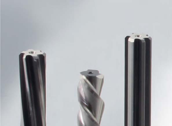
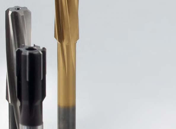
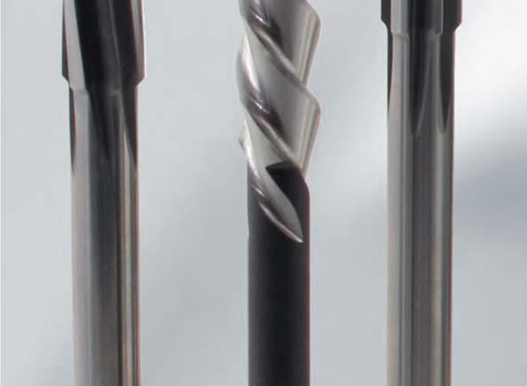
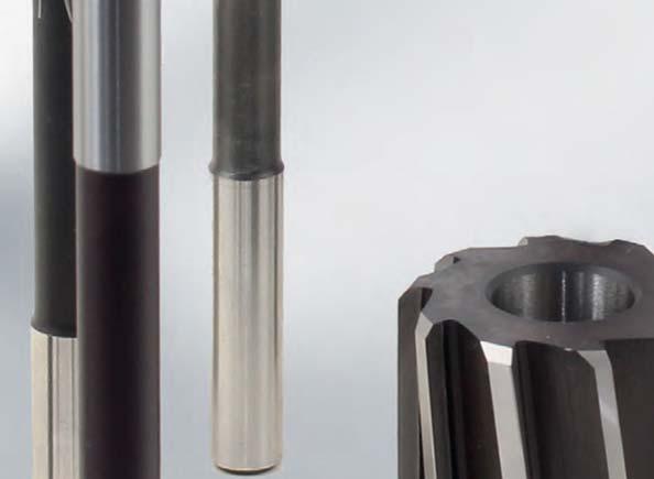

281 Reaming and Fine Boring Fixed multi-bladed reamers Machine reamers Machine reamers 281
282 Reaming and Fine Boring Fixed multi-bladed reamers Machine reamers Pin hole rough-turning reamer MDR510 DIN 2179, with taper 1:50, for reaming bores for taper pins DIN 1, DIN 258, DIN 7977 and DIN 7978 HSS- E DIN 2179 d 2 h 9 d 4 l 3 l 2 l 1 l 4 d 3 Cutting material suggestion P < 900 N M K1 K2 K3 N S H Cut SU344 SU344 SU344 Dimensions Specification Order No. ø ø d 2 ø d 3 ø d 4 l 1 l 2 l 3 l 4 z MDR ø1-SU MDR ø1.5-SU MDR ø2-SU MDR ø2.5-SU MDR ø3-SU MDR ø4-SU MDR ø5-SU MDR ø6-SU MDR ø6.5-SU MDR ø8-SU MDR ø10-SU MDR ø12-SU
283 Reaming and Fine Boring Fixed multi-bladed reamers Machine reamers Pin hole rough-turning reamer MDR510 DIN 2180, with taper 1:50, for reaming bores for taper pins DIN 1, DIN 258, DIN 7977 and DIN 7978, with Morse taper shank HSS- E DIN 2180 d 4 d 3 Cutting material suggestion P < 900 N M K1 K2 K3 N S H l 2 l 3 Cut SU344 SU344 SU344 l 1 Dimensions Specification Order No. ø ø d 3 ø d 4 l 1 l 2 l 3 MK z MDR ø5-SU MDR ø6-SU MDR ø8-SU MDR ø10-SU MDR ø12-SU MDR ø13-SU MDR ø14-SU MDR ø16-SU MDR ø20-SU MDR ø25-SU MDR ø30-SU MDR ø40-SU MDR ø50-SU Machine reamers 283
284 Reaming and Fine Boring Fixed multi-bladed reamers Machine reamers Hand taper reamer MDR510 DIN 9, with taper 1:50, with cylindrical shank and square (width across flats sw, see table), for reaming bores for taper pins DIN 1, DIN 258, DIN 7977 and DIN 7978 d 2 h 11 sw d 3 HSS Cutting material suggestion DIN 9 B P < 900 N M K1 K2 K3 N S H d 4 l 2 l 3 Cut SU344 SU344 SU344 l 1 Dimensions Specification Order No. ø ø d 2 ø d 3 ø d 4 l 1 l 2 l 3 sw z MDR510-9Bø3-SU MDR510-9Bø3.5-SU MDR510-9Bø4-SU MDR510-9Bø4.5-SU MDR510-9Bø5-SU MDR510-9Bø5.5-SU MDR510-9Bø6-SU MDR510-9Bø6.5-SU MDR510-9Bø7-SU MDR510-9Bø8-SU MDR510-9Bø9-SU MDR510-9Bø10-SU MDR510-9Bø12-SU MDR510-9Bø13-SU MDR510-9Bø14-SU MDR510-9Bø16-SU MDR510-9Bø20-SU MDR510-9Bø25-SU MDR510-9Bø30-SU MDR510-9Bø40-SU MDR510-9Bø50-SU
285 Reaming and Fine Boring Fixed multi-bladed reamers Machine reamers Hand taper reamer MDR500 DIN 204, with cylindrical shank and square (width across flats sw, see table), for finish-reaming of bores for morse taper HSS DIN 204C sw d 4 d 3 Cutting material suggestion d 2 h 11 P < 900 N M K1 K2 K3 N S H l 2 Cut SU344 SU344 SU344 l 1 Dimensions Specification Order No. For MK size ø d 2 ø d 3 ø d 4 l 1 l 2 sw z MDR Cø6.547-SU MDR Cø9.571-SU MDR Cø SU MDR Cø20.01-SU MDR Cø SU MDR Cø SU MDR Cø SU Machine reamers 285
286 Reaming and Fine Boring Fixed multi-bladed reamers Machine reamers Cutting data carbide machine reamers Cutting material Material Machining data ø [mm] < v c [m/min] Steel, < 700 N/mm² f [mm/u] 0,1-0,15 0,15 0,15-0,2 0,2-0,25 0,2-0,3 0,3-0,5 allowance a 0,1 0,1-0,2 0,1-0,2 0,2-0,3 0,2-0,3 0,3-0,5 P Steel, N/mm² v c [m/min] f [mm/u] 0,1-0,15 0,15 0,15-0,2 0,2-0,25 0,2-0,3 0,3-0,5 allowance a 0,1 0,1-0,2 0,1-0,2 0,2-0,3 0,2-0,3 0,3-0,5 v c [m/min] 8-12 Steel, N/mm² f [mm/u] 0,1-0,15 0,15 0,15-0,2 0,2-0,25 0,2-0,3 0,3-0,5 allowance a 0,1 0,1-0,2 0,1-0,2 0,2-0,3 0,2-0,3 0,3-0,5 v c [m/min] - M VA < 700 N/mm² f [mm/u] allowance a v c [m/min] - VA > 700 N/mm² f [mm/u] allowance a v c [m/min] Grey cast iron (GG) f [mm/u] 0,1-0,15 0,15-0,2 0,15-0,3 0,2-0,3 0,2-0,4 0,3-0,5 allowance a 0,1-0,15 0,1-0,2 0,1-0,2 0,2-0,3 0,2-0,3 0,3-0,5 K Spheroidal graphite cast iron (bis GGG 50) v c [m/min] f [mm/u] 0,1-0,15 0,15-0,2 0,15-0,3 0,2-0,3 0,2-0,4 0,3-0,5 allowance a 0,1-0,15 0,1-0,2 0,1-0,2 0,2-0,3 0,2-0,3 0,3-0,5 HU HP Spheroidal graphite cast iron (> GGG 50) Cu / Zn / Mg- alloy v c [m/min] f [mm/u] 0,1-0,15 0,15-0,2 0,15-0,3 0,2-0,3 0,2-0,4 0,3-0,5 allowance a 0,1-0,15 0,1-0,2 0,1-0,2 0,2-0,3 0,2-0,3 0,3-0,5 v c [m/min] f [mm/u] 0,12-0,16 0,15-0,2 0,15-0,3 0,25-0,35 0,2-0,4 0,3-0,5 allowance a 0,1-0,15 0,15-0,2 0,15-0,2 0,2-0,3 0,2-0,3 0,3-0,5 Alu-casting alloy (Si < 7%) v c [m/min] f [mm/u] 0,12-0,16 0,15-0,2 0,15-0,3 0,25-0,35 0,2-0,4 0,3-0,5 allowance a 0,1-0,15 0,15-0,2 0,15-0,2 0,2-0,3 0,2-0,3 0,3-0,5 N Alu-casting alloy (Si > 7%) v c [m/min] f [mm/u] 0,12-0,16 0,15-0,2 0,15-0,3 0,25-0,35 0,2-0,4 0,3-0,5 allowance a 0,1-0,15 0,15-0,2 0,15-0,2 0,2-0,3 0,2-0,3 0,3-0,5 v c [m/min] Plastics soft f [mm/u] 0,12-0,16 0,15-0,2 0,15-0,3 0,25-0,35 0,2-0,4 0,3-0,5 allowance a 0,1-0,15 0,15-0,2 0,15-0,2 0,2-0,3 0,2-0,3 0,3-0,5 v c [m/min] Plastics heavy f [mm/u] 0,12-0,16 0,15-0,2 0,15-0,3 0,25-0,35 0,2-0,4 0,3-0,5 allowance a 0,1-0,15 0,15-0,2 0,15-0,2 0,2-0,3 0,2-0,3 0,3-0,5 S Titanium v c [m/min] f [mm/u] allowance a H Hardened materials < 63 HRC v c [m/min] f [mm/u] allowance a 286
287 Reaming and Fine Boring Fixed multi-bladed reamers Machine reamers Cutting data machine reamers of HSS-E Cutting material Material Machining data ø [mm] < v c [m/min] Steel, < 700 N/mm² f [mm/u] 0,1-0,15 0,15 0,15-0,2 0,2-0,25 0,2-0,3 0,3-0,5 allowance a 0,1 0,1-0,2 0,1-0,2 0,2-0,3 0,2-0,3 0,3-0,5 P Steel, N/mm² v c [m/min] 8-12 f [mm/u] 0,1-0,15 0,15 0,15-0,2 0,2-0,25 0,2-0,3 0,3-0,5 allowance a 0,1 0,1-0,2 0,1-0,2 0,2-0,3 0,2-0,3 0,3-0,5 v c [m/min] - Steel, N/mm² f [mm/u] allowance a v c [m/min] - M VA < 700 N/mm² f [mm/u] allowance a v c [m/min] - VA > 700 N/mm² f [mm/u] allowance a v c [m/min] Grey cast iron (GG) f [mm/u] 0,1-0,15 0,12-0,16 0,15-0,2 0,2-0,35 0,2-0,3 0,3-0,5 allowance a 0,1-0,15 0,1-0,2 0,1-0,2 0,2-0,3 0,2-0,3 0,3-0,5 K Spheroidal graphite cast iron (bis GGG 50) v c [m/min] - f [mm/u] allowance a SU SP Spheroidal graphite cast iron (> GGG 50) Cu / Zn / Mg- alloy v c [m/min] - f [mm/u] allowance a v c [m/min] f [mm/u] 0,12-0,16 0,15-0,2 0,15-0,2 0,2-0,25 0,2-0,3 0,3-0,5 allowance a 0,1-0,15 0,15-0,2 0,15-0,2 0,2-0,3 0,2-0,3 0,3-0,5 Alu-casting alloy (Si < 7%) v c [m/min] f [mm/u] 0,12-0,16 0,15-0,2 0,15-0,2 0,2-0,25 0,2-0,3 0,3-0,5 allowance a 0,1-0,15 0,15-0,2 0,15-0,2 0,2-0,3 0,2-0,3 0,3-0,5 N Alu-casting alloy (Si > 7%) v c [m/min] - f [mm/u] allowance a Plastics soft Plastics heavy v c [m/min] f [mm/u] 0,12-0,16 0,15-0,2 0,15-0,2 0,2-0,25 0,2-0,3 0,3-0,5 allowance a 0,1-0,15 0,15-0,2 0,15-0,2 0,2-0,3 0,2-0,3 0,3-0,5 v c [m/min] - f [mm/u] Machine reamers allowance a S Titanium v c [m/min] - f [mm/u] allowance a H Hardened materials < 63 HRC v c [m/min] - f [mm/u] allowance a
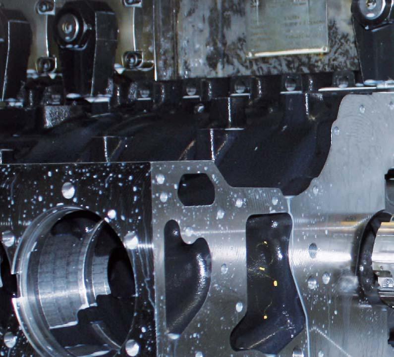
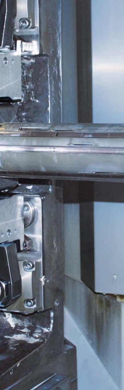

288 288


289 Reaming and Fine Boring Solutions Competence in practice As a specialist in the precision machining of bores with decades of experience, MAPAL offers an unrivalled range of tool solutions. Based on tried and tested standard and special solutions, tool designs are optimised and innovations incorporated, with a constant focus on how the customer will use them. The result is the best possible machining concepts for the widest variety of cutting tasks. Machining solutions tools with guide pads 290 Machining solutions EasyAdjust-System 292 Machining solutions fixed multi-bladed reamers 294 Complete solutions 296 Solutions 289


290 Reaming and Fine Boring Solutions Machining examples Machining examples Tools with guide pads Transmission housings Aluminium and magnesium pressure castings are increasingly used as a structural material in modern vehicles to achieve reductions in weight. Today s casting processes are very accurate and efficient, which also allows extremely complex workpiece geometry to be produced. One example of this is with transmission housings. The finish machining operation is carried out with combination tools with which several bores can be machined. The individual steps are designed with adjustable systems for the precision machining operation. Performance details: Transmission housing in AlSi9Cu3 Machining diameter 65 R7 Cutting speed vc = m/min Feed f = 0,1 mm The surface finishes required for machining wheel brake cylinders are extremely high, which makes finish machining by honing essential. An economic alternative here is to use a MAPAL twin-bladed tool with HX blades in PCD. The required surface quality of max. Ra = 0,3 μm is achieved with a tool life of more than 1000 parts. The microstructure of the surface is even improved as this does not produce a superficial effect but a surface with a high percentage contact area and deposits of lubricant. Performance details: Wheel brake cylinder in GG25 Spindle speed n = 2050 min -1 Cutting speed vc = 120 m/min Feed f = 0,3 mm Surface finish max. Ra = 0,3 μm Tool life > 1000 parts 290


291 Reaming and Fine Boring Solutions Machining examples Suspension arm Taper connections in machine manufacturing place the highest demands on surface finish, accuracy of pitch and concentricity deviations in order to ensure the decisive percentage contact area is achieved in the connection. In vehicle manufacture in particular, where safety-related components in steering or drive systems are mass produced, the necessary tolerances must be reliably met: a task which is predestined for the MAPAL taper reamers, due to the MAPAL principle of blade and guide pads which has also been applied in this context. Steering arms in vehicle manufacturing are an example of this. Performance details: Spindle speed n = 150 min -1 Feed speed vf = 67,5 mm/min Feed f = 0,45 mm Cutting speed vc = 8 m/min Slide valves for automatic transmission systems One machining example of the extraordinary precision which can be achieved with MAPAL adjustable precision machining tools with guide pads are control bores in slide valve housings and the actuating pistons for automatic transmission which run inside these. Roundness and concentricity of 2 μm are achieved, with tool life of 200,000 parts per blade and more. The control bores are machined with multi-step, singlebladed precision machining tools so that the coaxial result is also in the high precision range. For machining actuating pistons, MAPAL single-bladed external reamers are used. With these tools the MAPAL principle of blade and guide pads is practically reversed from external to internal, which also ensures optimum support during external machining operations. S ions 291


292 Reaming and Fine Boring Solutions Machining examples Machining examples with the EasyAdjust-System Precision tools for connecting rod machining Optimum surface qualities and a high level of dimensional consistency within close tolerances are demanded when machining the small and large pin bores of connecting rods. Fine boring tools with guide pads and EasyAdjust-System solve this difficult machining task precisely and cost-effectively. An additional measuring system on the machine and final finish-machining by honing become superfluous. Consistently high tool lives of the cutting edges with high precision are achieved even with minimum quantity lubrication (MQL). Combination tools for rough machining and finish machining of the small and large pin bores Special features: The tool combinations are equipped with ISO inserts for rough machining and HX blades with EasyAdjust-System for fine machining. In particular, modern lightweight connecting rods such as tapered or basket handle conrods can be machined completely. The chamfered or stepped side surfaces of the small pin bore result in interrupted cutting conditions and hence in more difficult machining conditions at the inlet and outlet during the machining of the bore. The tools with guide pads and EasyAdjust-System are able to perform this machining completely in one step both cost-effectively and precisely. Small end: Tapered or basket handle form High demands on the form and surface finish Unfavourable lead situation due to the interrupted cut High demands on axis parallelism Cylinder crankcases for car and motorbike engines are today generally made of aluminium. The matching bearing covers, however, are often made of spheroidal graphite cast iron (GGG) or sintered steel. This bimetallic combination demands high guide accuracy in order to ensure perfect circularity and cylindricity with varying cutting forces. Pilot machining Short, stable pilot tool for exact positioning and supporting for the subsequent machining. Thanks to the high precision of the tool, timeconsuming presetting with guide bearings can be waived on machining centres. Parts requiring no subsequent honing can be finish-machined ready for assembly with this pad-guided fine boring tool. Fine machining The up to 1200 mm long fine boring tool for the machining of the other ribs is inserted vertically through the first and/or second rib and machines the remaining bores with the highest precision with respect to straightness, parallelism and roundness. Thanks to simple and reliable handling of the blade adjustment, production is easily possible within an IT5 tolerance band. Special features: Four-blade: High feed rates, large savings in time Ideal starting situation for subsequent honing Bimetal combinations aluminium/ spheroidal graphite cast iron 292


293 Reaming and Fine Boring Solutions Machining examples Cost-effective machining of cylinder bores No matter whether GGV, GG or thermally sprayed coatings, the machining of the cylinder bore in engine blocks makes high demands on the fine boring tool in order to ensure that roundness and cylindrical form even in the delicate water jacket area. The boring of the cylinders represents a challenge not only from the point of view of quality demands, but also with respect to the machining time. Micro machining Using the six cutting edge tools with the cut distribution micro machining 4+2, feed rates of over 1,200 mm/min are possible thanks to PcBN cutting material. With their rapid and high-precision adjustment, the six cutting edges of the HX blade can achieve a total tool life of up to 24,000 bores per blade. With the short setting times of the EasyAdjust-System, the non-productive times can be very greatly reduced with this multibladed tool. Special features: Micro machining (4 semi-machining and 2 finishing blades) 4,000 bores per cutting edge Valve housings are the control centres in the hydraulics sector. The spool bores with their innumerable transverse galleries have to be machines with μ precision with respect to straightness, surface finish and dimensional tolerances. Rectangularity and smoothness, high surface finish quality and minimum circularity deviations with exact positions and concentricity are preconditions for comfort and durability of transmission parts. Multi-stage fine boring tools Special features: With the precision-ground TEC blade, workpiece finishing is quick and easy with minimum burr as the burr root is soft and easy to remove. Alternating cutting depths from diameter to face machining demand stable guidance of the tools as with the fine boring tools with guide pad technology of the EasyAdjust-System. Finish-machining by honing can be eliminated thanks to the latest cutting materials and geometries. Machining of valve housing: - Straightness Surface finish Ra Dimensional accuracy IT5, IT6 S utions 293


294 Reaming and Fine Boring Solutions Machining examples Machining examples Fixed multi-bladed reamers One example of the usage of HPR replaceable head reamers is forged steel universal joint forks. These parts transmit power in the drive train on vehicles. The requirements on the fine machining of the fork eyes are very high, particularly as the machining must be undertaken with an interrupted cut due to the shape. In one example surface finishes of R z 5 μm are obtained over a tool life of 6,000 parts on universal joint forks made of CK35 and C45 using the MAPAL HPR replaceable head reamer. On changing production from a conventional multi-bladed system to MAPAL HPR replaceable head reamers it was possible to increase the tool life from 2,000 to 6,000 parts and at the same time increase the feed rate from 1,000 to 1,500 mm/min and the spindle speed from 1,300 to 1,500 revs/min. Together with the extremely simple handling of the HFS system, there is a significant improvement in the cost effectiveness and the quality. Pump housing The machining of piston bores represents a typical application for HPR finely adjustable reamers. Even on the usage of PcBN blades, wear quickly occurs, the diameter tolerance can no longer be met. HPR finely adjustable reamers are then re-set up to 3 times and achieve four-times the tool life! Performance details: Piston diameter: ø 35 mm, 20 μm tolerance Tool: HPR finely adjustable reamer with 8 PcBN blades Machining values: vc = 300 m/min f = 1.2 mm/u Tool life: 600 pump housings or 3,000 bores 4 tool lives 2,400 pump housings or 12,000 bores 294


 5 μm circularity and cylindrical form Surface finish: R z 5 15 μm Tool: HPR200 / 6 blades (Cermet CU134) v c = 80 m/min and f = 0.")


295 Reaming and Fine Boring Solutions Machining examples An HPR finely adjustable reamer is also used for machining dowel pin bores in crankshafts made of 25MnCiS-iVB6. The bores are reamed to a diameter of 10K7 mm; a diameter tolerance of 15 μm is defined. The surface of the bores has a tolerance of R z 5 15 μm. The position coordinates of the bore play a crucial role in the machining; the circularity and cylindrical form are to be maintained to 5 μm. For this machining task the straight fluted MAPAL finely adjustable reamer HPR 200 is equipped with six cermet blades and machines the dowel pin bores at a cutting speed of 80 m/min and a feed of 0.6 mm. The HPR finely adjustable reamer from MAPAL achieves a tool life of 14,000 bores with one resetting. Material: 25MnCrSiVB6 Bore: ø10 K7 (tol. 15 μm) 5 μm circularity and cylindrical form Surface finish: R z 5 15 μm Tool: HPR200 / 6 blades (Cermet CU134) v c = 80 m/min and f = 0.6 mm Tool life with one resetting 14,000 bores Performance details: n = 150 min -1 vf = 67.5 mm/min f = 0.45 mm vc = 8 m/min Hydraulic value lifter bore in cylinder head For machining the hydraulic valve lifter bore in cylinder heads made of AlSiMg, the MonoReam reamer MOR805 with PCD blades is used. The bores are reamed to 12G7 and a surface roughness of R z = 6.3. Other specifications are freedom from burrs and cylindrical form < 8 μm. A special requirement on the tool is the geometry of the bore to be machined. This is a blind bore with a downward cut partially interrupted by an oil channel. This situation makes an optimal coolant supply and chip transport indispensable. The tool life of the previous tool was around 60,000 bores. By using a MonoReam reamer it was possible to meet and exceed the requirements; it was also possible to increase the tool life from 60,000 to 150,000 bores by re-adjusting twice. Performance details: Tool: MonoReam MOR805 with 6 PCD blades Diameter: ø12g7 mm Machining values: vc = 450 m/min Feed: f = 0.4 mm vf = 7,200 mm/min Tool life: 150,000 bores with two re-adjustments Cooling lubricant: Emulsion S ions 295

296 Reaming and Fine Boring Solutions Machining examples Machining examples complete solutions Clutch and gearbox housing for automatic gearbox and manual gearboxes High productivity due to MAPAL technology MAPAL tool specialists draw on particularly extensive experience during the design of complete processes for clutch and gearbox housings. The optimum machining of the large and often thin-walled parts requires a large amount of know-how, starting from the design of complex combination tools to the definition of housing clamping. The shaft bearing bores place special requirements in the μ range on shape, position, surface finish and diameter. Tool highlights in clutch and gearbox housings 1. Fine boring of the selector shaft cylinder A diameter tolerance of IT6 is achieved from the cored state. 2. Forward and backward machining of bearing bores The outer and inner surfaces as well as the bore are machined in one clamping position. 3. Drilling/countersinking combinations for oil filler bores The multi-blade configuration permits high machining values and stable cutting behaviour. The tool is designed as a combination with a thread milling cutter. 4. Face milling the joint face Due to specially matched cutting edge geometries, the defined surface roughness and surface structures can be achieved exactly. Advantages: Reduction in the machining time due to combination tools Highly reliable manufacturing due to many years of process experience Optimum concepts for all processes drilling, reaming, fine boring, circular/ face milling and thread cutting Complete support from planning to the breaking-in of the tools

297 Reaming and Fine Boring Solutions Machining examples Cylinder heads for two to twelve-cylinder engines New developments for lower cutting costs The complete machining of a cylinder head is a demanding task. The challenge is to meet high tolerance and quality requirements using precise tools that are as easy as possible to use, and that with low unit costs. The MAPAL tool package for the cylinder head includes many innovative solutions that satisfy the current development trends in engine manufacture. Tool highlights on the cylinder head 1. Reaming the valve guide and grooving the valve seat Coupled tools with high stiffness make complete machining possible in one step. The optimum exploitation of the cutting data minimise the cutting material costs. 2. Fine boring of the camshaft bearings Best position accuracy and concentricity are guaranteed by the pilot tool and the fine machining tool. 3. Boring the core plug bores The special chip removal prevents chips in the workpiece cavities. 4. Deep hole drilling for the oil channel High position accuracy is achieved by the special drill geometry. Triple feed rate compared to single-lip drill. Reliable chip removal via optimised chip flutes. Advantages: Modern tool concepts matched to the related manufacturing concept Usage of exactly matched cutting materials for example during the machining of the valve seat Special solutions for small production runs and prototypes Comprehensive range of services including tool management S ions 297

298 Reaming and Fine Boring MAPAL worldwide MAPAL competence MAPAL is the major specialist for complete machining tasks. As a result MAPAL offers complete tool know-how for machining parts. The programme ranges from high-performance standard tools to complex custom tools. Absolute precision is the basis for the quality of MAPAL tools. The result is dependable tool concepts that ensure reliable manufacture. Excellent quality in relation to surface roughness, circularity, cylindricity and maximum tool lives are the consequence. 298
299 Reaming and Fine Boring MAPAL worldwide MAPAL always close to the customer, everywhere. Quality, close customer contact, early information on developments and market requirements are the core objectives of MAPAL. Every day more than 4,300 employees in the MAPAL Group prepare new, appropriate solutions for the machining tasks of our customers. With continuous training and further training of employees and the constant interchange of experience, MAPAL safeguards its high technological standards and guarantees that proverbial MAPAL quality. The sites of the MAPAL Group Subsidiaries Representatives Germany MAPAL Dr. Kress KG in Aalen MAPAL WWS GmbH in Pforzheim MAPAL ISOTOOL GmbH in Sinsheim MILLER GmbH in Altenstadt Rudolf Strom GmbH in Vaihingen/Enz August Beck GmbH & Co. KG in Winterlingen WTE Präzisionstechnik GmbH in Kempten Australia Valcor Australia Sales Pty. Ltd. in Ballarat, Victoria Brazil MAPAL do Brasil Ferramentas de preçis ão Ltda. in Belo Horizonte China France Great Britain India Italy Japan MAPAL China Production and Trading Ltd. in Shanghai MAPAL France S.A.S. in Le Chambon Feugerolles MAPAL France Bureau Villepinte in Paris MAPAL Ltd. in Rugby MAPAL INDIA Private Ltd. in Bangalore MAPAL Italia S.R.L. in Gessate/MI MAPAL KK in Tokyo Korea Malaysia Mexico Poland Singapore MAPAL HTT Co. Ltd. in Kyunggi-Do MAPAL Malaysia Sdn. Bhd. in Selangor Darul Ehsan MAPAL FRHENOSA S.A. de C.V. in Monterrey MAPAL Narzedzia Precyzyjne Spólka z o.o. in Posen MAPAL Sales Office South East Asia South Africa MAPAL SPECTRA Carbide Tooling Technology in Port Elizabeth Taiwan Thailand Czech Rep. USA MAPAL Precision Tool System Co. Ltd. in Tainan MAPAL THAILAND Co. Ltd. in Bangkok MAPAL CZ s.r.o. in Dlouhá Lhota MAPAL Inc. in Port Huron MI
 7361 585-0 Fax +49 (0) 7361 585-1029 info@de.mapal.com www.mapal.com Order number 10137424 V2.1.0 REI-E-01-010-0115-HD Printed in Germany.")
300 MAPAL the major specialist Reaming and fine boring Boring Drilling Milling Turning Actuating Clamping Setting and measuring Services V2.1.0 MAPAL Präzisionswerkzeuge Dr. Kress KG P. O. Box 1520 D Aalen Phone +49 (0) Fax +49 (0) Order number V2.1.0 REI-E HD Printed in Germany. Right of technical information reserved. MAPAL Dr. Kress KG
Standard programme. Multi-bladed reamers and counterboring tools. The tool specialists for the trade.
 Standard programme Multi-bladed reamers and counterboring tools The tool specialists for the trade. 2 STANDARD PROGRAMME Introduction Welcome to the world of precision! Founded in 1906 by August Beck as
Super. Line. 10th Edition SUPER PRICE SUPER QUALITY SUPER AVAILABILITY
 Super Line SUPER PRICE SUPER QUALITY SUPER AVAILABILITY 10th Edition High-tech tools at a super price convincing price-performance-ratio exceptional quality immediate availability customer-friendly service
Clamping technology. MAPAL Floating holder. for multi-bladed high performance reamers NEW
 Clamping technology MAPAL Floating holder for multi-bladed high performance reamers NEW 2 Floating holder for MAPAL multi-cutting reamers When using reamers on lathes it is often necessary to compensate
Standard Programme Clamping Technology. The tool specialists for the trade.
 Standard Programme Clamping Technology The tool specialists for the trade. Direction Leipzig 4 Direction Dresden Direction Erfurt Chemnitz 72 95 The tool specialists for the trade. WTE Präzisionstechnik
Actuating Tools. MAPAL Competence Actuating Tools and Facing Heads
 Actuating Tools MAPAL Competence Actuating Tools and Facing Heads The MAPAL ISOTOOL Competence Center in Sinsheim The MAPAL group develops, produces and markets high quality precision tools worldwide
Modules for fine machining. Guhring modules 6x6 and 4x4. NEW: Module 6x6
 NEW: Module 6x6 simple, quick and highly accurate setting of 6-fluted tools minimal tension thanks to 6 setting elements perfect balancing with 6 balancing screws Modules for fine machining Guhring modules
Solid carbide Twist Drills Overview
 Solid carbide Twist Drills Overview Manufacturer ß 000000000000 DIN similar to 899 338 338 338 6539 6539 6539 6539 6539 6539 6539 6539 6539 Counters.cut.Counters.cut. 3 x D 3 x D 3 x D, IKZ 3 x D, IKZ
Accessories, spare parts and measuring equipment
 Accessories, spare parts and measuring equipment The broad range of accessories, spare parts and measuring equipment represents a useful addition to the range of actual clamping tools and offers spare
Performance requires quality.
 131 - With straight shank and square - Left-hand spiral 7-8 - First cut 1/4 of the cutting length (l 2 ) - Accuracy Hand Reamers DIN 26. Not suitable for blind holes. d 1 l 2 l 1 d 2 131 2, 25 5 1,6 21
Standard product line MEGA-Speed-Drill. MEGA-Speed-Drill-Inox MEGA-Speed-Drill-Iron. The tool specialists for the trade.
 The tool specialists for the trade. Standard product line MEGA-Speed-Drill Available immediately as 5xD version : MEGA-Speed-Drill-Inox MEGA-Speed-Drill-Iron The tool specialists for the trade. MILLER
Hole Finishing.
 Tool Selection Guide.................................................................K4 K5 Application Examples...............................................................K6 K92 Reaming Tools...................................................................K94
Extremely small dimensions, extremely high precision.
 Product innovations Edition 2011-1 Drilling and threading _TOOL INNOVATIONS IN DRILLING Extremely small dimensions, extremely high precision. SOLID CARBIDE DRILLS Walter Titex X treme the universal high-performance
HSS ground for steel to 900 N/mm 2, aluminium alloys, brass, bronze. Use For producing screw through-holes DIN EN 20273,
 Drilling Tools Step drills 184 Step drills T - Countersink angle - With straight shank - Cone envelope grind - Web-thinned chisel edge and surface treatment For producing threaded core holes and countersinks
PCD REAMER PCD Reamers Catalogue. Wuxi Sundi Precision Tools Co.,Ltd. Content. Tel:
 PCD REAMER 2016-2017 PCD Reamers Catalogue Email: info@sudicuttingtools.com Overview PCD Reamer Production Performance Content E1 E2 E3-E5 E5 E Tel: 0086-0510-88207357 Fax:0086-0510-88207362 Quality Control
tough. Live Centers Face Drivers 2013/2014
 tough. Live Centers Face Drivers 2013/2014 www.roehm.biz LIVE CENTERS - FACE DRIVERS Revolving tailstock centres Basic 2005 Heavy 2009 Speed 2011 Slim 2012 Control 2014 Flex 2015 Revolving centering tapers
Standard Programme Common Price List 2016 CLAMPING TECHNOLOGY. The tool specialists for the trade.
 Standard Programme Common Price List 2016 CLAMPING TECHNOLOGY The tool specialists for the trade. 2 STANDARD PROGRAMME Introduction HIGH PRECISION MADE IN GERMANY WITH COURAGE TO INNOVATE! WTE Präzisionstechnik
PCD REAMER. Content PCD Reamers Catalogue. Overview PCD Reamer Production Performance Quality Control Sundi Standard
 PCD REAMER 2015-2016 PCD Reamers Catalogue Content Email: info@sudicuttingtools.com Tel: 0086-0510-88207357 Fax:0086-0510-88207362 Overview PCD Reamer Production Performance Quality Control Sundi Standard
Info Overview - solid carbide twist drills (I) Drilling Tools
 Drilling Tools") Info Overview - solid carbide twist drills (I) Brand 0 0 0 0 0 0 0 0 Company standard Company standard Company standard Company standard 6539 6539 6539 6539 5 x D Countersink Countersink Article number
Info Overview - solid carbide twist drills (I) Brand 0 0 0 0 0 0 0 0 Company standard Company standard Company standard Company standard 6539 6539 6539 6539 5 x D Countersink Countersink Article number
BEST OF 2014 January December
 Best of 2014 BEST OF 2014 January December 2405 K POWER CHUCK 3274 SELF-CENTRING SCROLL CHUCK 3 JAW 3, 60o serrations, through hole. Interchangeable with Kitagawa type B-200 Cast iron, plain back, front
Live and Dead Centres
 s w i t z e r l a n d Live and Dead Centres 1. Live-Centres 1.1 Main-Line ROTOR Main-Line, the approved top of the range for lathes and grinding machines. Very precise and robust construction. Made for
CONTENTS Adaptors Technical Information Brazed Cutters Cutting Parameters Services 62
 CONTENTS 4-19 20-35 Adaptors Technical Information Brazed Cutters Cutting Parameters 36-41 42-53 54-59 60-61 Services 62 Modern machining operations need to rely on the optimization of the production processes:
Metalworking ETP HYDRO-GRIP. Achieve Excellence through Simplicity. Hydraulic high precision toolholders
 Metalworking ETP HYDRO-GRIP Hydraulic high precision toolholders Achieve Excellence through Simplicity 2017 ETP HYDRO-GRIP Hydraulic high precision toolholders HYDRO-GRIP high precision tool holders are
Hole Finishing.
 Tool Selection Guide.................................................................K4 K5 Application Examples...............................................................K6 K92 Reaming Tools...................................................................K94
PROFIMAT MC/RT. Key data. The compact production machine
 A member of the UNITED GRINDING Group The compact production machine Key data Whether precision, profile, internal or external cylindrical grinding the PROFIMAT MC is a highly efficient grinding centre
3-01 INTERNAL GRINDING
 3-01 INTERNAL GRINDING 9.3.2016 3-02 INTERNAL GRINDING Type Sketch Details Stock Page INFORMATION Diameter, rigidity of the shank, grinding stroke, special executions 3-04 As small as a proboscis of a
HOLLFELDER CUTTING TOOLS. Special tooling for customer applications
 HOLLFELDER CUTTING TOOLS Special tooling for customer applications HOLLFELDER-GÜHRING CUTTING TOOLS Your competent partner in the area of metal chip removal. At our two company locations in Nuremberg und
Driven Toolholders for MAZAK Machines
 Driven Toolholders for MAZAK Machines We do Specials! Manufacturer of Precision Tools since 1974 Table of Contents Type Page Driven Toolholders QTNX 100 + SQT 10 8-15 QTNX 200 / 250 + SQT 15 + SQ 200 /
POWER PRICE UNI. powerful UNF METAL. UNCPower. power ful GOLD FOR. powerful TOP GEOMETRIES UNF PERFECT CHOICE VER. perfect thread form.
 MADE BY UNIVERSALtaps TOP GEOMETRIES FORM EUNIVERSAL UNIVERSAL TAPS powerful perfect UNF longideal flutes choice tool life PROCESS RELIABLE PERFECT universal power ful UNC-THREAD ISO-METRIC THREADS GUHRING
METAL DRILLING. Metal Drilling ENGINEERED FOR CONTROLLED PRECISION AND SPEED 118 SPLIT POINT 118 STANDARD POINT 135 SPLIT POINT TURBOMAX JET POINT
 128 METAL DRILLING ENGINEERED FOR CONTROLLED PRECISION AND SPEED The IRWIN line of metal drill bits offers of a solution for every professional application. Each metal drill bit is made of high speed steel
Compatibility overview of accessories for drilling machines
 Compatibility overview of accessories for drilling machines Convincing arguments: quality, efficiency and price Direct-SSBF MT 2 3050571 MT 2 3050572 MT 3 3050573 MT 4 3050574 Precision-SSBF 0-8 mm 3050608
TAPER AND DEBURRING COUNTERSINKERS
 TAPER AND DEBURRING OUNTERSINKERS Taper and deburring countersinkers The flutes of the new RUKO highperformance taper and deburring countersinkers are BN ground from the fully hardened material. Because
Holemaking ADVANCES 2017 Inch
 Holemaking ADVANCES 2017 Inch Holemaking Introduction... Q1 Q8 Solid Carbide Drills... R1 R139 Modular Drills...S1 S51 Indexable Drills... T1 T60 Hole Finishing... U1 U95 Q1 Holemaking Made Easy and Economical
Mining & Construction Tools. Technical Information for Brazed Tools. General Cutting Tools. Rotating Brazing Tools
 BRAZED TOOLS Technical Information for 02 KORLOY Ultra-Fine Grades : F-Series 02 Corrosion & Magnetism Proof Grade : IN-Series General Cutting Tools 03 Cemented Carbide, Cermet Blank 04 Square Blank 06
BEST OF 2015 January December
 BISON opens its new manufacturing facility improving quality and service 53,000 sq. metre site 33,600 sq. metre of manufacturing State of the art design and manufacturing under one roof BEST OF 2015 January
Tooling for Swiss Automatics
 Tooling for Swiss Automatics MANUFACTURED IN SWITZERLAND Swiss Precision Tools I S O 9 0 0 1 CERTIFIED SWISS PRECISION SWISS QUALITY Providing tolerances unmatched in the industry TIR (in) REGO-FIX Cylindrical
Industrial Tooling Corporation Ltd. Product Catalogue Issue 10
 Industrial Tooling Corporation Ltd. Product Catalogue Issue 10 Company Profile Company Profile ITC is a round tool specialist. Our objective is simply to provide you, our customer, with the correct cutting
Guide units. For toolmaking, fixture manufacturing and machine engineering
 Guide units For toolmaking, fixture manufacturing and machine engineering Guide units in compliance with DIN, ISO and STEINEL standards or according to your specifications Guide pillars Guide and pillar
Pneumatic spindles Pneumatic built-in motors
 Pneumatic spindles Pneumatic built-in motors MANNESMANN DEMAG Always one step ahead Intelligent solutions to save time and costs As an insider you know that being at the cutting edge of automation is crucial
Clamping Tools
 Clamping Tools Drill chuck Tapping chuck/ tapping machines Taper bore tools HSK inserts Tool holder for lathes Tool pre-setter 1 1.3 1.8 Reduction sleeves Spindle Sleeves Ejector Drifts Adapter sleeves
CNC swiss and non-swiss. turning center TNL32
 CNC swiss and non-swiss turning center TNL32 Thanks to the outstanding technical features of the TRAUB TNL32 CNC swiss and non-swiss turning center, you will notice measurable improvements in production.
Specializing In High Performance Solid Carbide Cutting Tools
 Specializing In High Performance Solid Carbide Cutting Tools High Performance Products For Shops That Seek Productivity SERIES 156 VAR-A-TECH SERIES 101 ROUGHER SERIES 191 PRO-4 Vol. 0213 Series 110 for
A member of the UNITED GRINDING Group. The Art of Grinding. PRODUCT RANGE. The Art of Grinding.
 The Art of Grinding. A member of the UNITED GRINDING Group The Art of Grinding. GLOBAL PERFECTION CUSTOMER FOCUS PRECISION TECHNOLOGY LEADER GLOBAL EFFICIENCY SAFETY SOPHISTICATED PROCESSES The Art of
CERATIZIT designation system
 C5 CEATIZIT designation system Tool holders UTS / HSK-T system Assembly size (system) MSS system E = external / I = internal Assembly size Hand Approach angle Parting and grooving depth Shank section,
enduring. Drill Chucks NC-Tooling 2013/2014
 enduring. Drill Chucks NC-Tooling 2013/2014 www.roehm.biz DRILL CHUCKS - NC-TOOLING Keyless drill chucks EXTRA 1004 EXTRA-RV 1005 SUPRA 1006 SUPRA-SK 1008 SUPRA-SK E 1008 SPIRO - SPIRO-SK 1009 Key-type
Contents. Milling. Solid end mills
 UPDATE 2016-2 SOLUTIONS & SUPPORT By choosing Seco, you get more than just a comprehensive portfolio of advanced metal-cutting solutions and expert services. You get a partnership based on trust, respect
Metalworking ETP HYDRO-GRIP. Achieve Excellence through Simplicity. Hydraulic high precision toolholders
 Metalworking ETP HYDRO-GRIP Hydraulic high precision toolholders Achieve Excellence through Simplicity ETP HYDRO-GRIP Hydraulic high precision toolholders HYDRO-GRIP high precision tool holders are your
CTR Counterboring Tools
 CTR Counterboring Tools Primary Application Designed for high production screw head counterbores and similar counterboring operations. The S2 S inserts produce a precise 90 bottom. The ground radial land
Special Product Catalogue. T-A Drill Insert System
 Special Product Catalogue T-A Drill Insert System T-A Special Products - Application Example Automotive Cylinder Head Application - Cylinder Head Water Jacket Holes Application - Cylinder Head Water Jacket
machine tools for railways
 machine tools for railways RAFAMET S.A. Comprehensive solutions, advanced technologies and cost efficient productivity now much more than ever before are obvious requirements that the right equipment supplier
Victory M1200 Series...B2 B27. M1200 Mini...B2 B21 M1200 HD...B22 B27. M690 Series...B28 B32. M270 Series...B34 B40. M370 Series...
 Indexable Milling Victory M1200 eries.................................................................................b2 B27 M1200 Mini..................................................................................B2
Table of Contents. Standard Taps
 Table of Contents Standard Taps Standard Taps--High Speed Steel Machine Screw Sizes... 3 Standard Taps--High Speed Steel Hand Taps (Fractional Sizes)... 5 Standard Taps--High Speed Steel Machine Screw
BEST OF A selection of our most popular products. To view the complete range visit
 BEST OF 2016 January December A selection of our most popular products To view the complete range visit /products Welcome to BISON Empowered By Precision BISON opens new manufacturing facility making it
THe BeST OF THe BeST OF NeW. NeW. NeW. empowered. by precision. empowered. empowered precision. A selection of our most popular products
 THe BeST OF 2017 A selection of our most popular products THe BeST OF 2017 AA selection selection of of our our most most popular popular products products To view the complete complete range range visit
Scandinavian Tool Systems AB is a Swedish based manufacturer and supplier of tools for thread turning, thread milling, parting off and grooving.
 Edition 2015-10 Scandinavian Tool Systems AB is a Swedish based manufacturer and supplier of tools for thread turning, thread milling, parting off and grooving. The main product is the QuadCut, which on
Universal. CNC Turning machine TNA500 TNA600
 Universal CNC Turning machine TNA500 TNA600 TRAUB TNA this name is highly regarded throughout the world for machining large chuck, shaft or bar parts. With their precision and efficiency, short setup time
YOUR PARTNER FOR THE MACHINING OF CRANKSHAFTS AND CAMSHAFTS. A Company of the SWAROVSKI Group
 YOUR PARTNER FOR THE MACHINING OF CRANKSHAFTS AND CAMSHAFTS A Company of the SWAROVSKI Group www.tyrolit.com TYROLIT TECHNOLOGICAL LEADER AND PARTNER ON EQUAL FOOTING TYROLIT has been developing innovative
IT.TE.DI. Milling. TEDI MILL The Perfect Answer. TEDI MILL PCD Shell Type Face Mill Cutters Integral Face Mill Cutters
 IT.TE.DI. Milling 03 TEDI MILL PCD Shell Type Face Mill Cutters Integral Face Mill Cutters TEDI MILL Cartridges 04 08 14 20 TEDI MILL The Perfect Answer TEDI MILL CBN Shell Type Face Mill Cutters Integral
GFS - Backspotfacing System RSQ for small-lot production
 GFS - for small-lot production The GFS back spotfacing system, type RSQ, is a heavy-duty, simple tool with rapid payback and extremely inexpensive owing to the interchangeability of the proven GFS cutters
Motors Automation Energy Transmission & Distribution Coatings. Flat-frame Motors K1F / K2F
 Motors Automation Energy Transmission & Distribution Coatings Flat-frame Motors K1F / K2F WEG Group WEG is a leading global solutions provider for drive technology, energy generation and distribution,
Carbide Drills When productivity matters - Stub 1. to Long 1
 CARBIDE DRILLS Carbide Drills When productivity matters - Stub 1 to Long 1 hole depths - With & without internal coolant - Ultra fine grain type carbide - Technically advanced multi-layer coatings Drill
Endmills. Drills. Reamers. Where high performance is the standard. Countersinks Edgehog. Burrs. Performance, Precision, Economy
 Edgehog Where high performance is the standard Performance, Precision, Economy For more than 90 years, M.A.FORD has been at the cutting edge of tooling design and manufacture and has developed an enviable
GUHROSync Synchro tapping chucks. the Best of. Guhring - your world-wide partner
 the Best of BOTH SYSTEMS The advantages of Hydraulic chucks & in one tool holder Now also available with ISO taper, MAS/BT and straight shank GUHROSync Guhring - your world-wide partner GUHROSync THE EASY
ACE LOCK Milling Chucks
 ACE LOCK Milling Chucks Run-out accuracy: 10 µm/0.0004 at the distance of 100 mm/4.00 from the end of the holder. Milling Chucks Spiral slits are precision-machined with a laser securely hold the cutter
SHRINK FIT CHUCKS CAT BT HSK CAPTO.
 SHRINK FIT CHUCKS CAT BT HSK CAPTO www.haimer.com HAIMER SHRINK FIT TECHNOLOGY Features Benefits 360 Clamping, Multiple planes Precision bore, no wear components No mechanical moving parts Induction shrink
Compatibility overview of accessories for drilling machines
 Compatibility overview of accessories for drilling machines Accessory items for drilling B13 B14 B16 B20 B25 B32 RB 6T RB 8S B17 Pro B23 Pro/Vario B26 Pro/Vario B33 Pro/Vario B16 H/Vario B24 H/Vario B28
Good reasons to use Albrecht drill chucks
 3 * Good reasons to use Albrecht drill chucks Quality 2-phase quality control e.g. 100% run-out accuracy test (similar to DIN 10888) parts made to fit each other exactly working parts are case-hardened
Drilling tools. From page Centring drills NC spot drills. Twist drills HSS, HSS/ Co, solid carbide. From page 10-6
 tools entring drills N spot drills From page 10-3 Twist drills HSS, HSS/ o, solid carbide From page 10-6 Step drills one drill bits arbide masonry drill Bit tools From page 10-44 ircle cutters T-A Insert
PCD & CBN TANGENTIAL MILLING
 & TANGENTIAL MILLING CONTENTS Highlights 4 Codifiy 6 Shell Type 7 Cylindrical Type 8 Monoblock Type 9 Inserts 12 Adaptors 18 Setting Procedures 24 Spare Parts 26 Cutting Parameters 31 HIGHLIGHTS HIGHLIGHTS
Table of Contents. Standard Taps
 Table of Contents Standard Taps Standard Taps--High Speed Steel Machine Screw Sizes... 2 Standard Taps--High Speed Steel Hand Taps (Fractional Sizes)... 4 Standard Taps--High Speed Steel Machine Screw
Pneumatic spindles Pneumatic built-in motors
 Pneumatic spindles Pneumatic built-in motors MANNESMANN DEMAG Always one step ahead Intelligent solutions to save time and costs As an insider you know that being at the cutting edge of automation is crucial
WORKHOLDING SYSTEMS
 www.ptgworkholding.co.uk WORKHOLDING SYSTEMS INSTALLATION & PRE-LOADING INSTRUCTIONS INSTALLATION & PRE-LOADING INSTRUCTIONS Pre-load Flats Machine Drawbar M/C Spindle Pre-load Adjustment Screw Mandrel
WINNER! ALBRECHT. Precision Chucks
 WINNER! ALBRECHT Precision Chucks At present, the Albrecht APC is the best performing chuck world wide. In the area of speed, tool life and safety. 3 4 You can expect: A clearly higher chip removal rate
The technologically minded. Automotive. industry. Technologies, solutions for automotive industry
 The technologically minded Automotive industry Technologies, S olid c arbide ttools, ools, P KD and HSS Solid carbide PKD solutions for automotive industry 2 3 oo ver the last 50 years Diager Industrie
Reamers - Hand - Machine (Morse Taper & Chucking) - Bridge - Taper Pin - Morse Taper Socket - Taper Pipe - Adjustable
 - Bridge - Taper Pin - Morse Taper Socket - Taper Pipe - Adjustable") REAMERS Reamers - Hand - Machine (Morse Taper & Chucking) - Bridge - Taper Pin - Morse Taper Socket - Taper Pipe - Adjustable the ultimate reference book is here... BLACK BOOK The ultimate reference book:
REAMERS Reamers - Hand - Machine (Morse Taper & Chucking) - Bridge - Taper Pin - Morse Taper Socket - Taper Pipe - Adjustable the ultimate reference book is here... BLACK BOOK The ultimate reference book:
IT.TE.DI. Milling. TEDI MILL The Perfect Answer. TEDI MILL PCD Shell Type Face Mill Cutters Integral Face Mill Cutters
 IT.TE.DI. Milling 03 TEDI MILL PCD Shell Type Face Mill Cutters Integral Face Mill Cutters TEDI MILL Cartridges 04 08 14 20 TEDI MILL The Perfect Answer TEDI MILL CBN Shell Type Face Mill Cutters Integral
COMPETENCE IN PRECISION AND QUALITY HOLE SAWS
 COMPETENCE IN PRECISION AND QUALITY HOLE SAWS Tungsten carbide hole saws, shallow cut Cutting edges: tungsten carbide Material thickness: up to 4 Cutting depth: up to max. 10 Cutting angle: works standard
Special Product Catalogue. T-A Drill Insert System
 Special Product Catalogue T-A Drill Insert System T-A Special Products Introduction Allied Maxcut - where special is the norm Tell us your application and we ll make the tool - guaranteed. With more than
Cutting
 wist drills Miniature drills Sheet metal drills Core drills Step drills Centring and spot drills aper pin drills Solid carbide drills Solid carbide tapping ools Carbide reversible cutting inserts wist
Geared scroll chuck with optimized design
 Geared scroll chucks Geared scroll chuck with optimized design Benefit from proven quality in optimized design. A splash water edge at the upper chuck edge is used as additional protection of the spindle
> clamping force up to kn. > operating pressure up to 500 bar. > piston with internal thread. > for push- and pull operation
 Block CYLINDERS for VARIOUS DESIGN APPLICATIONS > clamping force up to 155.5 kn > operating pressure up to 500 bar > piston with internal thread > for push- and pull operation > with longitudinal and cross
Various duties efficiently solved EMCOMAT E-300 E-360 E-400. [ means:
 [ E[M]CONOMY] means: Various duties efficiently solved EMCOMAT E-300 E-360 E-400 Cycle-controlled lathes with high-powered cutting performance and maximum precision EMCOMAT E-300 [Headstock] - Siemens
MQL Shrinkfit holders
 Technical Sales Guide MQL Shrinkfit holders Release for sales: 04-2017 Publication: SN2017-2 Internal use only 1 Internal use only 2 1 Contents 2 Executive summary / Introduction... 4 2.1 What is MQL?...
Taper shank arbors for drill chucks
 KD Taper shank arbors for drill chucks Taper shank arbors KD Tool group A04 Type 236 Taper shank arbors with drill chuck taper DIN 238 completely hardened and ground Item no. Morse taper DIN 228 B Hole
Creating and using [ MECOF ] [ EMCO ]
![Creating and using [ MECOF ] [ EMCO ]](/thumbs/76/73649374.jpg "Creating and using [ MECOF ] [ EMCO ]") Creating and using [ MECOF ] Mecof is one of the leading manufacturers of high speed and high precision milling and boring machining centres. With many years of experience and an extensive know-how, Mecof
Creating and using [ MECOF ] Mecof is one of the leading manufacturers of high speed and high precision milling and boring machining centres. With many years of experience and an extensive know-how, Mecof
SP / LP SERIES. Ultra Performance Bridge Type Vertical Machining Center AWEA MECHANTRONIC CO., LTD. ISO 9001 ISO 14001
 SP / LP SERIES Ultra Performance Bridge Type Vertical Machining Center AWEA MECHANTRONIC CO., LTD. HEADQUARTERS 629, Suezhetou Section, Kwanpu Rd., Wenshan Li, Hsinpu, Hsinchu 5, Taiwan TEL : +886-3-588-5191
MATSUMOTO and NEIDLEIN maintain a partnership for the production and supply of face drivers, live centers, and dead centers on a worldwide basis.
 ULTRA-LIVE CENTERS DEAD CENTERS MATSUMOTO and NEIDLEIN maintain a partnership for the production and supply of face drivers, live centers, and dead centers on a worldwide basis. NEIDLEIN live centers and
Reliable series-produced components
 Reliable series-produced components Demag wheel range Demag wheel systems Reliable solutions for every application Contents Page Demag DRS wheel block system 6 Demag LRS travel wheel system 14 Demag RS
d -2,5 26,5 mm D -3,4 33 mm L mm; МК D mm L mm D mm L mm
 KAMAZ Publicly Traded Company Repair and Tooling Plant Tool making 2018 Twist drills Auger drills Drills with a thickened core Centre drills Twist step drills Solid carbide drills Inserted-blade drills
STEADYLINE FOR TURNING & MILLING REDUCE VIBRATIONS & INCREASE PRODUCTIVITY
 STEADYLINE FOR TURNING & MILLING REDUCE VIBRATIONS & INCREASE PRODUCTIVITY OVERCOME TOOL OVERHANG CHALLENGES When using long overhang tools to machine difficult-to-access areas, such as deep cavities or
UNIVERTOR A. Pick-up-turning centre. The systems supplier for manufacturing technology from one source
 The systems supplier for manufacturing technology from one source A flexible pick-up turning system for small, medium and large-volume production UNIVERTOR A Pick-up-turning centre Pick-up-turning procedure
Hüller Hille NBH 5X 5-Axis Machining The New Benchmark for Complete Machining
 Hüller Hille NBH 5X 5-Axis Machining The New Benchmark for Complete Machining The economic 5-axis machining is found in all industrial areas today. With two different concepts NBH machining centers can
VTC VERTICAL TURNING CENTRES
 VTC VERTICAL TURNING CENTRES VTC VERTICAL TURNING CENTRES VERTICAL TURNING CENTRES precision VTC VERTICAL TURNING CENTRES DANOBATGROUP is one of the largest machine tools and production systems manufacturers
MAXXMILL Vertical milling center for 5-sided machining MILLING
 MAXXMILL 400 630 750 Vertical milling center for 5-sided machining MILLING EMCO-WORLD.COM MAXXMILL 400 Compact vertic 1 MACHINE BED Machine bed and slide systems made of solid welded steel and cast iron
HIGH PRECISION HIGH PERFORMANCE
 Tool holders www.haimer-usa.com HIGH PRECISION HIGH PERFORMANCE HAIMER Family owned & operated since 1977 Global Headquarters located in Igenhausen Germany North America operation and stocking facility
Body Length (mm) New Tool Ref Length (mm)
 New Tool Ref Length (mm)") 3 Series olders Thread to BSPT & ISO 7-1 G L5 L4 L2 & GEN2 D1 D Flanged Straight Shank older Reference Number older Type Flute Type elical Fluted Design L3 L1 Available Ex-Stock D L1 L2 L3 L4 L5 D1 G *
3 Series olders Thread to BSPT & ISO 7-1 G L5 L4 L2 & GEN2 D1 D Flanged Straight Shank older Reference Number older Type Flute Type elical Fluted Design L3 L1 Available Ex-Stock D L1 L2 L3 L4 L5 D1 G *
GMS SERIES Tool Spindle Type 5-axis Turning Centers
 GMS SERIES Tool Spindle Type -axis Turning Centers BRAND NEW MULTI-TASKING MACHINING TECHNOLOGY The tooling spindle and turret can support twin spindle machining. Special tooling system design to provide
Geared scroll chuck with optimized design
 Geared scroll chucks Geared scroll chuck with optimized design Benefit from proven quality in optimized design. A splash water edge at the upper chuck edge is used as additional protection of the spindle
1. TAPS AND SCREW-PLATES ASCO machine Tap for horology and equipment high-speed steel
 1. TAPS AND SCREW-PLATES ASCO machine Tap for horology and equipment high-speed steel SPIROLEX 10 / 3G NIHS For brass, traversing holes, with 2 helicoidal grooves. Helix at left, perfectly countersinking
Standard with cone bushing. Backlash-free Safety Clutch
 EAS -Compact ratchetting clutch/synchronous clutch The Backlash-free Safety Clutch for Standard with cone bushing Packaging Machinery Machine Tools Paper Machinery Indexing Drives Servo Motors EAS -NC
and 2013 Beyond Inserts
 INNOVATIONS Innovations MASTER Master Catalogue CATALOGUE A4 CUTTING Tooling TOOLS and 2013 Beyond Inserts 2013 A4 Tooling and Beyond Inserts for All Your O.D. and I.D. Applications Primary Application