World s best prices on ebikes
|
|
|
- Baldwin Strickland
- 6 years ago
- Views:
Transcription
1 29 May 2018 World s best prices on ebikes Dear Valued Customer, Congratulations on owning your new Leitner electric bicycle! Up to now electric bikes have been far too expensive for everyday use, except for some hobby enthusiasts the Leitner electric bike range has changed that. Now everyone can ride an ebike, no license or registration required. The Leitner ebike makes transportation on an electric bike fun, cheap and easy. Like us on Facebook for exclusive specials, newest products, and big giveaways! For early access to specials subscribe to our newsletter at Leitner is one of Australia s fastest growing electric bike brands, investing large amounts of time and resources into service and continual improvement and therefore we highly value Your feedback. Please contact us with any feedback. Review us on Leitner is 100% Australian owned. Thanks for shopping with Leitner! Kind Regards, Ephraem Leitner and the Leitner team Leitner Pty Ltd ABN ph: sales@leitner.com.au IMPORTANT NOTICE Read manual, Instructions and Terms carefully before use. It is the buyer s responsibility to make sure the electric bicycle is safe to ride. If necessary ask for help at any good local bicycle store. Please keep the invoice. By purchasing and using a product from Leitner, the customer accepts the terms and conditions and warranty published at including and It is the customers' responsibility to service and maintain the products regularly and to make sure that the product is safe to use before each ride. Contact customer support at sales@leitner.com.au or for any questions and in case repairs are needed. Leitner does not accept claims for repairs which were performed without our approval. Leitner does not assume any product liability to the extent permitted by the law.
2 Battery Care & Storage Charge battery after every ride. It is not necessary to fully discharge battery before charging. Lithium batteries do not have any memory effect, so you can charge them at any time. Lithium batteries must not be stored if fully discharged. If your battery is fully discharged, charge it as soon as possible. Storing the battery if fully discharged for long periods will damage the battery. It is recommend to store the batteries fully charged and then charge it at least every two months. It is not necessary to leave the charger connected to the battery if stored for long periods. Just top the charge up every two months. If batteries are not charged at least every two months, the battery may be damaged and such damage is unfortunately not covered under manufacturer's fault warranty. Leitner
3 Safety Warnings Riding a bike can result in serious injury or death. It is important to read the manual carefully, wear safety equipment, including a helmet and always ride carefully. It is important that you check all nuts, screws, and spokes are tight before each ride and to make sure that the tyres are inflated and that all brakes work. If you are not confident about doing this yourself, make sure you get someone competent to do it for you. We do not always tighten parts before we send the bicycle to you. It is your responsibility to make sure that the bike is safe to ride before each ride. Please read the safety warnings in the printed manufacturer manual. Do not ride the bike in the rain and store undercover. Make sure the bike stand is always retracted before riding and clear of obstacles. Do not sit on bike and put weight on stand. Only ride on flat surfaces. Do not ride down curbs or similar obstacles. Hitting the stand against obstacles while riding may cause damage to frame and such damage is not covered by warranty against manufacturer's fault. Minimum recommended rider age 18 years. It is the users responsibility to comply with local road rules. Switch off pedal assist when you are riding in tight situations, e.g. turns, because pedal assist can turn on suddenly and momentarily accelerate the bike, taking you by surprise. The PAS (Pedal Activation System) is designed for safety so the motor does not get power until the pedals are turned. However if the throttle is turned on by pressing the red button in on the right side of the handle bar, then the bike will move immediately when the throttle is twisted. So to avoid accidentally twisting the throttle we recommend you turn off the key immediately when you park the bike before you dismount. Protection against rust: Bikes must not be in contact with sea water. Living close to the sea increases risk of corrosion and it is recommended to treat parts like spokes and forks with commercial rust protector available from hardware stores. Do not apply any lubricants to brake parts as it will reduce brake performance. Assembly instructions If you need any support please contact us on or sales@leitner.com.au Please also refer to the detailed assembly guide with pictures below. We believe ebikes make the world a better place and we believe they should be affordable for everyone. Shipping them directly from our warehouse to you makes it possible for us to offer them at the lowest prices, not like brick and mortar ebike stores which sell similar models for twice the price. Smaller packaging means a lower shipping cost, that is why some parts of Leitner ebikes need assembly. Please use the following instructions and the provided manual and multi-tool to help you assemble the ebike. There may be slight variations between the different models. If you need help contact us or have the ebike assembled at any good local bicycle store. It is recommended to remove the bike from the box on a rug so the bike will not get scratched. Lay the box down and drag the bike out horizontally. The current packaging consists of the seat, a cardboard box (with manual, charger, and parts) and the ebike. Carefully remove the protective packaging from the bike. The handle bar is attached to the frame by the brake, gear, and electrical cables. The following parts need assembly: 1)Front mudguard & headlight 2)Front wheel 3)Handle bar 4)Rear rack 5)Pedals 6)Seat 1) Front mudguard & headlight. Remove the protector from the front fork where you will later install the front wheel. The front fork is bent towards the bottom which should face forward. Install the headlight and the front mudguard with the same bolt on top of the fork. Arrange headlight bracket on bolt first, then the mudguard, then tighten the bolt. There are two bolts on the lower part of the fork, one on each side, to fix the support arms of the mudguard to the fork. The electrical connectors to the headlight are delicate.
4 the red wire connects to the "+" pin, the black to the "-" pin. The "+" and "-" symbols are small and you need to look carefully to identify them. If that does not work try reversing them. If you have a small cable tie, secure the cable to the support bracket so it won t get accidently snagged. You may also use duct tape to help keep the cables in position. 2) Install the front wheel. Check for loose spokes, also on the back wheel, and take the wheels to a bike mechanic if they need to be tightened. The quick release axle is usually tied to the spokes. Remove the quick release axle. Remove the nut and one spring and insert the quick release axle through the hole in the center of the wheel. Sometimes there are small plastic parts inside the whole and you need to push them out carefully. Keep a spring on each side of the wheel. The springs are there just to make gaps to make it easier to install the wheel in the forks. Screw the nut on the axle a little and then position the wheel between the forks. Position the wheel so that the disc of the disc brake goes into the slot in the front brake caliper housing. Keep your eye aligned with the brake slot. If you can see a brake pad blocking the disc then use an Allen Key on the tool to screw the pad back out of the way. Be patient, you can do it! Adjust the quick release axle nuts so you can clip it tight with the quick fit lever. NOTE: Brake pads may not be installed on your bike. Check that the brakes work when you have finished installing the wheel(s). If the brakes do not work you must install the pads. The discs may make a noise when passing the brake pads. This is normal and will go away after a few weeks. You may finetune the pad position by correcting the inner and outer brake pads using an allen key. Make sure the brake pads allow the wheel to turn freely. 3)Install the handle bar in the jaw of the stem. Keep your eye out for a small part that will be loose when you open the jaw. Insert the handle bar and align it in the center. Make sure the cables from the handle bar are not tangled up and the steering can be turned to the full extent. Double check every single bolt and screw is tight on the handlebar so nothing can happen when you are riding. Don t over tighten the bolts as it may damage the ball bearings. 4)Rear Rack: The Rear rack has two support arms to fix onto the frame behind the battery. Loosen the nuts of the support arms, one on each side, pull the support arms out and fix them to the bike frame with the nuts and bolts which sit there already. Make sure the rack sits tight before use. 5)Pedals: Have a look at the pedals threads, there should be a L for left and an R for right pedal. Lubricate the threads with appropriate bike lube and screw them into the crank. The L pedal screws in the opposite direction of normal threads. 6)Seat: insert the seat into the seat bar, make sure the seat is inserted to at least the minimum insertion mark which is marked on the seat post. The seat must not be extended beyond that minimum insertion mark, otherwise it may damage the frame. The minimum insertion mark must not be visible when the seat is installed. Check that the seat is tight. It is recommended to insert the seat post at least 10cm into the frame. Adjust the quick fit mechanimsm by turning the bolt until it s tight. Functions of turning the key on the battery: All the way clockwise: ON. Turn it back anti-clockwise: OFF. Turn it back again anti-clockwise and push in: Battery can be removed. The battery charging socket is on the opposite side of the battery. The socket protector can be flipped sideways to expose socket.
5 What if the Pedalling Assistance mode doesn t work? The pedalling sensor may not be set up correctly: When using Pedalling Assistance mode, it will use the disc that is about 6 cm in diameter on the right pedal side of the pedals-axle at the bottom of the bike's frame. That disc has several little magnets in it. When the pedals are turned the magnets go past a little sensor which is hanging from the frame under the pedals-axle. The sensor tells the controller (under the battery) how fast you are turning the pedals. The tip of the sensor has to be about 1 mm from the disk. Make sure it is that close by either sliding the disk along the pedals-axle (or bending the sensor bracket towards the disk). The bike [pedal assist] will not go if the sensor is not close enough to the disc! Folding bikes Before riding a folding bike make sure the frame and handle bar quick folding mechanism is closed tightly and it is safe to ride the bike. If the frame makes squeaking noises during riding tighten the nut of the frame quick folding mechanism. How to fold the bike frame: open quick fix lever, turn bolt to the left then push bolt up. It may be necessary to jiggle the bolt while pushing up for the first few times. To close the frame complete the steps in reverse order. Tyre pressure Please check the recommendation on the tyres and inflate accordingly. The current model s pressure recommendation is between 40 and 65 psi. We recommend 50. Adjusting the derailleur Refer to the manual for details. In many cases turning the barrel adjuster corrects shifting issues. Please also check out the video link in the addon. How to reduce vibration Tighten the screw on the rear light with a Philips screw driver. Turning the pedals makes noise The chainguard may rub on the chain. Observe where the rubbing occurs. If it s the chainguard try to increase the distance of the chainguard from the chain by bending the metal clip which holds the chainguard. Fuse specifications (Fuse is located on battery next to lock) Please check engraving on fuse to confirm. Finally, perform a safety check on the tightness of all nuts, bolts, spokes, and screws. Ask your local bicycle shop for a chain lubricant. Enjoy your ebike! Kind Regards, Ephraem Leitner and the Leitner team Leitner Pty Ltd ABN ph: sales@leitner.com.au
6 Terms and Conditions Please refer to our website for Terms and Conditions including Warranty
7 v28jul2015.com.au World s best prices on ebikes Manual add-on: Assembly instructions with pictures Dear Customer, Please find below an add-on to the assembly instructions with pictures. It provides additional information about: - Installation of front wheel, front mudguard, headlights and handlestem - Adjustment of disc-brakes - Installation of pedals - Functions of the battery - How to fold the seat for battery removal - How to use the controls (throttle and pedal assist mode) - How to fold the frame (folding models only) - Removing and re-installing the rear wheel - Tuning the rear derailleur of shimano gears (youtube video link) If you need any help please don t hesitate to call us on or sales@leitner.com.au Important Notice: It is the buyers responsibility to make sure the electric bicycle is safe to ride. If necessary also ask for help at any good local bicycle store.
8 Before you start: Check the bike for damage or missing parts Please note that ebikes are fragile items. Although we are using first class courier services and the bikes are professionally packed it may happen that they get damaged during transit. Please check the bike for damage upon arrival andletusknowimmediately.wewillthenworkwithyouona solution. If there are any missing parts please also let us know immediately and we will send a replacement part as soon as possible.

9 Contents ebike Saddle Box with Charger and Parts

10 Installation of front wheel, headlights and front mudguard Remove black protective bar From front fork
 Fix mudgurad to fork here On both sides This part of fork facing forward.")
11 Top bolt: first insert Headlight, then front Mudguard, then tighten bolt (The two sockets with threads pointing forward are not used. They are for installation of V brakes which are not needed since the bike is equipped with front disc brakes.) Fix mudgurad to fork here On both sides This part of fork facing forward. Insert front wheel axle here Brake callipers (need to face left hand side). The disk of the front wheel needs to be on the left hand side and needs to be inserted between the two Brake pads on the left hand side of the fork. If the brake pads are too close together and impair installation of front wheel, the distance between the pads can be increased using allen keys to make it easier to install the front wheel. Please refer to the disk brake guide below.

12 Pull out black protector of threads from front wheel. Please note there may plastic residues inside the axle hole. You may have to push the Residues out carefully when inserting the axle.

13 Nut, spring spring, quick release One side of the front wheel Other side of the front wheel
14 Prepare the quick release axle for installation of front wheel. Remove the spring and the nut.

15 nx Disc brake pads Disc Carefully place front wheel threads into fork. make sure the disc goes between the two break Pads of the disc brake. Refer to disc brake section for further help. Leitner

16 Insert axle. Sometimes there may be plastic residues inside the axle hole which need To be pushed out with the axle. Don t use extreme force.

17 Insert axle until it s visible from the other side Insert one spring onto axle threads on this side and fasten nut until the wheel is securely tightened when you close the quick fit lever on the other side.
18 Quick fit lever in closed position


19 Connecting the front light:model HL 1900 Connect black wire at the - pole Connect red wire at the + pole Mount the light using the bolt and mudguard at the front fork as shown above. (models Libelle, Tirol, Berlin, Venice ) Leitner
20 Installation of pedals Attention! Read this guide before installing the pedals! Don t use force when inserting the pedals into the threads! The threads on the crank arms will be damaged (stripped) if the pedals are installed incorrectly (using force) and replacement parts need to be purchased at the cost of the customer if that occurs.

21 Step 1: Look closely to identify the left and right pedal. They have different threads! It can be a bit tricky to see the L or the R, but it s very important to pick the correct pedal. L for Left pedal R for right pedal
")
22 Step 2: Lubricate the thread of the pedals with lubricant (available from bike shops)

23 90 Degrees (straight) Step 3: Carefully position the pedal at a 90 degree angle (straight) to the crank arm. Use your hands. Don t use a tool. Don t use force! The left pedal needs to be turned anti-clockwise into the crank arm on the LEFT side of the bike, The right pedal needs to be turned clock-wise into the crank arm on the RIGHT side of the bike The pedal will screw in without resistance if it s placed correctly into the thread. If you feel resistance, don t continue! Un-screw the pedal and start again.
 and tighten the pedal up very firmly so that it won t come off while riding.")
24 Step 4: Use your hands to screw the pedal all the way in, so that the thread is not visible anymore. Once it s all the way in, use a spanner (red arrow) and tighten the pedal up very firmly so that it won t come off while riding. Remember : clock-wise for the right pedal and anti-clockwise for the left pedal. It is necessary to check that the pedals are tight regularly as they may loosen up over time.
. Don t overtighten.")
25 Crank arms Check the allen bolt at the centre of both crank arms, left and right hand side. (right arm shown in picture). If the arms are loose, tighten the bolt with a large allen key (key not supplied). Don t overtighten. It is necessary to check the crank arms regularly as they may get loose over time. Leitner 2015


26 Handle stem hinge on Libelle and Tirol The hinge at the base of the handle stem of the Libelle and Tirol is at 45 degree angle. This makes it possible to fold the stem down nicely on the side of the bike. Leitner
 of about 45 degrees. This is normal. It makes it possible to fold the handle-stem towards the side of the bike (see next page).")
27 Handle Stem for Tirol and Libelle Folding bikes The base of the handle stem of the folding bikes Tirol and Libelle is at an angle (red lines) of about 45 degrees. This is normal. It makes it possible to fold the handle-stem towards the side of the bike (see next page). Leitner


28 Open the quick-release of the folding handle-stem and fold the handlebars to the side of the bike. Make sure that the bolt (red arrow) in the centre of the handle-stem is tight, and that the bike is safe to ride, however don t overtighten it. Magnification of handle-stem base when folded. Leitner

29 Leitner SuperT Dual-suspension folding bike Leitner
 and the centre suspension (S). The seat pole MUST NOT TOUCH the centre suspension.")
30 Leitner SuperT Distance of seat pole from centre suspension P S MUST NOT TOUCH! Before riding the SuperT make sure that there is sufficient room between the seat pole (P) and the centre suspension (S). The seat pole MUST NOT TOUCH the centre suspension. A distance of at least 5mm is recommended. If the seat pole is lowered too much it may touch the suspension. Raise it and make sure that it won t touch the suspension when riding. Leitner

31 Leitner SuperT Foldable Handle-Stem Black round clip Loop of quick-release Before riding the SuperT make sure that the handle-stem is installed properly and that It s safe for riding. The quick-release must be closed and hold the handle-stem hinge in place safely. The loop of the quick release must be secured by the black round clip and held in place in an upright-position. First, close the quick-release, move the loop into an upright position, then turn the black round clip and use it to secure the loop. Leitner

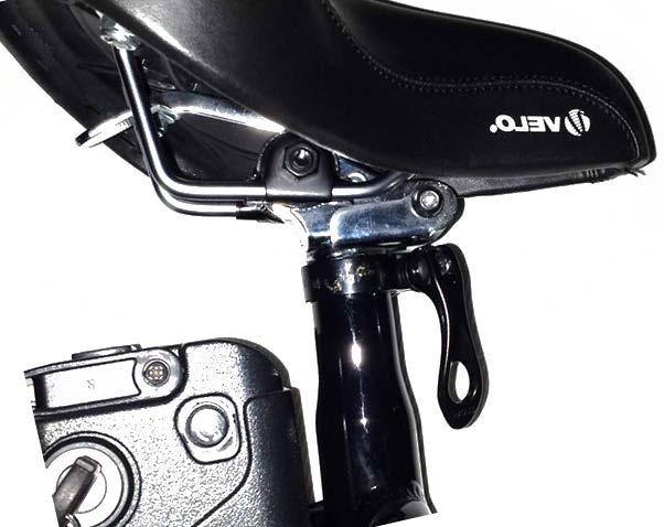
32 Zoom Handle-stem on Cruisers Models Leitner
33 Attention! Make sure the handle stem & handle bar are installed safely before riding the bike. If unsure feel free to contact us or ask for help at a local bicycle store. Leitner
 securely with the large hex key. Don t over tighten.")
34 T Insert the handle-stem into the frame. Tighten the bolt (red arrow) securely with the large hex key. Don t over tighten. Top-view, tighten the bolt (red arrow) Leitner
. To change the position of the handle- STEM loosen the bolt on the bottom (right picture) with an allen key.")
35 T Top-view Bottom-view To change the position of the handle-bar, first loosen the bolts (red arrows) on the top (left picture). To change the position of the handle- STEM loosen the bolt on the bottom (right picture) with an allen key. Leitner
36 Once the handle-stem and handle-bar are in the desired position, tighten up all bolts. Put the front wheel between your knees and test if the handle-stem moves when turning the handlebar. It should not move easily and it needs to be stable when riding the bike. It is ok for the handle-bar to move when you are using force. Don t over tighten. Leitner
37 Important information about disc brakes Disc brakes are considered to perform better than standard v-brakes, especially in wet conditions. Please note that brand new disc brakes need braking in. This means it may take a few weeks until they perform optimally. Ride your bike very carefully and allow plenty of time for braking. Please find below a guide on how to adjust the disc-brakes. You may have to re-adjust them several times during the brake-in period. Brakes need to be re-adjusted regularly, also after the brake-in period. This is normal as brake pads will wear down. Before each ride, make sure that both front and rear brakes work well and follow the guide below to maintain the brakes. If you need any help, please contact us on or ask your local bike shop for help. It is your responsibility to make sure the brakes are maintained correctly before each ride and that the bike is safe to use. Leitner
38 Adjusting the disk brakes Simply put, a disc brake consists of a disc which is between two brake pads (inner and outer brake pad). See picture below. Pushing the brake lever will push the outer pad against the disk and the inner pad. The friction will cause the bike to slow down. The pads need to be adjusted to be as close to the disc as possible without rubbing much. Slight rubbing is normal initially and will get better after the break-in phase.

39 Frontal view of disk brake I O I: Inner brake pad disk O: Outer brake pad The distance between the brake pads and the disk should be as small as possible without causing rubbing of the pads against the disk. The tiny gap can be best seen against white background Red box: see magnification on next page
40 Magnification I O I: Inner brake pad O: Outer brake pad Red arrows: point at tiny gap between pads and disk Disk: blue arrow Adjust to make the gap as small as possible without rubbing Tocheckifthebrakesarerubbingliftthewheel, spin itand listen for rubbing sound. Brake pads can be moved very close to the disc for best performance. This may cause slight rubbing which is normal. If there is a lot of rubbing and the wheel is slowed down without braking, increase the brake pad distance.
Turnheretofinetunecabletension Brake cable 2) Loosen this allen bolt, adjust cable tension, then tighten bolt.")
41 Howtoadjusttheouterbrakepads 1) Before adjusting the brakes, push and release the brake lever 10 times. This tightens the brake cables. They may loosen up again in time and you mayhavetorepeatthisstep. 3)Turnheretofinetunecabletension Brake cable 2) Loosen this allen bolt, adjust cable tension, then tighten bolt. The more tension on the cable, the smaller the distance between the brake pad and the disc.

42 How to adjust the inner brake pads Adjust inner brake pads: Turn clockwise: reduce distance of brake pad to disk Turn anti-clockwise: increase distance of brake pad to disk Leitner


43 Before you turn the keys: Align Battery correctly The round metal bolt (black arrow) of the battery lock needs to be aligned correctly with the opening in the silver metal bar. Push the battery down or lift the battery up to align the bolt with the opening. If it s not aligned correctly, the bolt will hit the silver metal bar and you can t turn the key and the bolt won t come through the hole.
.")
44 Functions of battery & lock (insert key and turn) Attention! Always handle the battery lock with care. Never use force! Battery needs to be in the "ON" position when pushing the white button on top to check battery charge (2 green lights, full, 1 green light, battery discharging, red light only: charge battery soon). 1) 2) 3) 1) Off, battery can be removed (push key in when turning towards 2) Off, battery locked into frame (push in when turning to "1") 3) ON, battery locked into frame Attention. PUSH THE KEY INTO THE LOCK GENTLY when turning between positions 1 and 2! When turning between 2) and 3) DON't push the key into the lock, just turn normally.

45 Aluminium rail which holds battery The silver aluminium rail which holds the battery is attached to the frame with a screw. Use a Phillips screw driver to tighten the screw. The battery should be inserted along the aluminium rail with care. Don t use force. Don t bend the aluminium rail.

46 Charging the battery C Leitner Electric Bikes are equipped with quality Lithium batteries. Lithium batteries are a modern technology which is not suffering from memory effects like some older battery types, which means that Lithium batteries can be charged anytime, also e.g. if they were only half discharged. This will not reduce the battery life. To charge the battery, move the Cover (C) gently to the side, connect the charger to a power point and then connect the charger to the battery. Leitner
47 Charging the battery The chargers are smart chargers, which means they will automatically stop charging when the battery is full. There are two charger types. Charger Type A) Has ONE LIGHT on the charger. If it s RED, it means it s charging the battery. If it s GREEN, it means the battery is fully charged. Charger Type B) Has TWO LIGHTS on the charger. If BOTH LIGHTS are RED, it means it s charging the battery. If ONE LIGHT is GREEN and ONE LIGHT is RED, it means the battery is fully charged. ATTENTION: the charger can get very hot while charging. Always keep it away from material which can catch fire. Leitner
48 Charging the battery The battery takes about 5 hours to charge if It s completely discharged. If it s not fully discharged it will take less time to charge. It is recommended to switch the battery OFF while charging. Leitner
 firmly push the white button on top of the battery and hold it down.")
49 Checking the battery charge In order to check the battery charge, you need to switch D the battery ON with the key. Please refer to the section functions of battery. Once the battery is switched ON, there are two ways to check the battery charge: 1) firmly push the white button on top of the battery and hold it down. If the battery is fully charged, there will be two green lights and one red light on the display (D) on top of the battery. If the battery discharges, one green light will disappear, then the second green light will disappear and if the red light disappears, the battery is fully discharged. Leitner
 to H (high, refer to arrow) The more red lights are lit, the higher the voltage.")
50 Voltage Display D 2) The battery Voltage is displayed on the on the left hand side of the handle bar. There are 4 red lights ranging from L (low) to H (high, refer to arrow) The more red lights are lit, the higher the voltage. Please note the voltage may drop when bike is being ridden and the voltage may be lower as the battery is discharging. Voltage may not drop in a linear fashion and it is only an estimate of remaining battery charge. To check battery charge, please refer to previous page Leitner
51 Battery Care & Storage Charge battery after every ride. It is not necessary to fully discharge battery before charging. Lithium batteries do not have any memory effect, so you can charge them at any time. Lithium batteries must not be stored if fully discharged. If your battery is fully discharged, charge it as soon as possible. Storing the battery if fully discharged for long periods will damage the battery. It is recommend to store the batteries fully charged and then charge it at least every two months. It is not necessary to leave the charger connected to the battery if stored for long periods. Just top the charge up every two months. If batteries are not charged at least every two months, the battery may be damaged and such damage is unfortunately not covered under manufacturer's fault warranty. Leitner
52 How to use the controls Attention! When going around corners it is recommended NOT to use the electric motor as it may cause you to fall due to the sudden acceleration. It is recommended NOT to use the throttle and NOT to pedal if the pedal assist mode (PAS) is on, when going around corners. The motor of the bike can be activated with the controls of the bike. The throttle is located at the right hand side of the handlebar. Twisting the throttle accelerates the bike. The current models top speed using the throttle is 6km/h (walking speed). The throttle only provides a small "push" at take-off. To achieve higher speeds, please use the Pedal Assist Mode and RELEASE THE THROTTLE. The throttle overrides the PAS, which means if you keep the throttle twisted all the way down, the bike won't go faster than 6km/h. The throttle can be upgraded to go 25km/h whithout pedalling (off-road use only). Please refer to the end of this manual for instructions around page 80. The Pedal Assist Mode controls are located at the left hand side of the handle bar. It will activate the motor when you are pedalling. The current models top speed using pedal assist mode is 25 km/h. In order to use the bike as a push bike, push the - button until there won t be any lights on the Pedal Assist Display. Please find more details on the following pages

53 Left hand: Pedal Assist control and voltage display Battery Voltage Display L:Low H:High Battery Voltage varies during a ride, e.g. it is lower uphill. It can be used to read the battery charge on flat terrain using pedal assist mode. An easy way to check the battery charge is to push the button on top of the battery (The key must be in the "ON" position). 2 green lights: full. 1 green light: medium charge. red light: low charge: connect battery to charger. A A head and rear-lights Pedal Assistance display ON/OFF button One light: low motor assistance Two lights: medium motor assistance Three lights: high motor assistance No lights: no motor assistance (push bike mode) Push + and - buttons to change level of motor assistance

54 Right hand: throttle Twist and go throttle Twist down to accelerate Release to stop acceleration Throttle ON/OFF button


55 Maximum Seat Height Make sure you never exceed the minimum insertion point on the seat post when you adjust the seat height. There is a line with "Minimum" engraved on the seat post as per picture. It is recommended to insert seat post at least 10cm into frame. The minimum insertion mark must not be visible when the seat is installed. Magnification of Seat Post with engraved writing Leitner
 (SuperT does NOT have folding sesat.")
56 How to fold up the seat for battery removal (different seat model shown) (SuperT does NOT have folding sesat.) Push up quick release

57 Fold seat up Note: The battery on the SuperT folding bike can be removed by opening the seat quick-release and twisting the seat. There is no folding seat post on the SuperT model.
58 Lowering the seat The seat can be lowered by changing the way it s attached to the seat post and also by cutting the seat tube (frame). Only lower the seat if you are comfortable with these instructions and always make sure that the seat is mounted safely in order to avoid injury. If necessary ask for help at a local bike shop.
59 Lowering the seat attachment Nut Tools needed: wrench (1/2 imperial or adjustable wrench) Loosen the nuts (one on each side) with a wrench Leitner

60 Brackets Carefully remove one nut and remove the bolt slowly to release the brackets. There are two brackets on each side of the seat. The seat can now be taken off the seat post. Leitner
 by loosening the nuts and re-tightening them. Test if the seat can still be folded up easily.")
61 Turn the brackets upside down (180 degrees) and mount the seat to the seat post by inserting the bolt and tightening up both nuts. The seat is now lower. The seat can be tilted (forward and backward) by loosening the nuts and re-tightening them. Test if the seat can still be folded up easily. If there are any issues move the slide seat forward or backwards till it folds up easily. Leitner
62 Leitner

63 Cutting the seat tube Cut here 2 cm The seat tube (red) can be cut by about 2 cm to lower the seat, using e.g. a hacksaw to cut the aluminium alloy. Remove the black quick release ring before cutting. It is recommended not to cut off more than 2cm as the seat tube will lose flexibility and it may not be possible to tighten the black quick release ring in order to keep the seat in position when the seat is raised. Use a file to soften any sharp edges to avoid injury. Use a bit of lubricant to protect the fresh cut from corrosion. Please note that any damage caused by cutting the seat tube is not covered by the warranty of the frame. Leitner
, red arrow, to move the support arms.")
64 Installing the rear rack Install the rear rack as shown in the picture above. You may have to loosen the nut (or allen bolt), red arrow, to move the support arms. Make sure the rack is stable and safe before using it.
 turn left. 3) push up and wiggle until you hear the click.")
65 Folding the frame (folding models only) Fold your ebike in seconds: 1) open the quick-release. 2) turn left. 3) push up and wiggle until you hear the click. Fold the frame.

66 Fold the frame and fold the handlebar. Folding bikes fit into most car boots. The handle-stem folds towards the RIGHT side of the bike.
 by hand anti-clockwise in half turns until the gears switch smoothly.")
67 Tuning of the gears (rear derailleur) If the gears don t switch smoothly, they need adjustment. It is recommended to lubricate the chain to insure optimal performance. The gears can be adjusted in most cases by turning the barrel (red circle) by hand anti-clockwise in half turns until the gears switch smoothly. If that doesn t help, it may be necessary to turn it clock wise. If that doesn t help please refer to the detailed tuning video below. Leitner
68 Tuning of rear derailleur Follow below link for an excellent youtube video about rear derailleur adjustment Servicing the bike and regular maintenance Have the bike serviced by your local bike shop after assembling it to make sure it's safe to ride and tension and true all spokes before starting to ride the bike. It is necessary to service the bike regularly and have all parts including the spokes, brakes and gears adjusted regularly. The electric parts don't need to be serviced, therefore servicing can be done at a push-bike shop. Leitner
69 Enjoy your ebike If you need any help please don t hesitate to call us on or sales@leitner.com.au
70 Removing and re-installing the rear wheel Summary: w Removing the rear wheel 1)Switch the bike off and remove the battery 2)Remove cable ties and disconnect motor cable 3)Remove black caps on both side of axle and loosen bolts with wrench Putting the rear wheel back on 1) Fit axle back into openings making sure that the tooth of the washer is at the opening and making sure that the disc of the disc brakes is between the disc brake calipers 2) Tighten up bolts until the rear wheel is securely fit and put black caps back on 3) re-connect the motor wire to the female connector, making sure both arrows point at each other. Use cable ties to secure cable to frame

71 Removing and re-installing the rear wheel w Switch the bike off and remove the battery Remove cable ties using scissors Or a paper knife

The rear wheel motor cable is now")
72 1)Hold on to the male and female end of the cable and pull them apart into the direction of the red arrows. 2)The rear wheel motor cable is now disconnected


73 Remove cable from the clip (push back, Bring forward through the middle of the clip) Leitner

74 Loosen black cap and expose nut If you can t access the nut with a wrench remove the two screws holding the rear mud-guard and derailleur protector.

75 Use a wrench to loosen the nut (anti-clock wise).

76 Do the same on the other side: remove black cap, expose nut Leitner
77 Use wrench and loosen nut(anti-clockwise)

78 The wheel can now be removed

79 Opening for wheel axle insertion When putting the wheel back, make sure the tooth of the metal washer is in the opening where the wheel axle is inserted. This is true for both sides of the wheel. Make sure the disc of the disc brake goes in between the brake callipers. This view is from the bottom of the bike. Leitner

80 Bottom-up view at the other nut. Note the tooth of the washer is in the opening for the axle.
. Use cable-ties to secure the cable to the frame. Cable ties are available at your local hardware store, e.g.")
81 Tighten up both nuts until the wheel is safely installed, cover with black caps, re-install the derailleur protector and reconnect the motor wire to the female end: both arrows need to point to each other (see inside red box). Use cable-ties to secure the cable to the frame. Cable ties are available at your local hardware store, e.g. Masters or Bunnings.
82 v10december2014 Activating the 25km/h throttle Leitner
83 Important legal note! Leitner electric bikes are built to strictly comply with Australian road rules. For 250 watt bikes, this means that the throttle speed is limited to walking speed, under 6km/h in the factory setting, in order to comply with the norm called EN It is the European Ebike Norm which was adapted by Australia. Please find more info here: e-import-laws/ Many customers were asking for a throttle which allows the bike to go 25km/h without pedalling. We have now included a feature in Leitner electric bike models from December 2014 onwards to unlock the throttle. It involves opening the controller box under the battery and unclipping the grey wires (see instructions below). Please note that after unlocking the throttle your ebike will no longer comply with the EN15194 standard and may be illegal in your state for use on roads. Therefore the bike should NOT be used on public roads if the throttle is unlocked to go 25km/h. The bikes should only be used OFF ROAD. Although there are very few reports of the law being enforced, you may receive heavy fines for riding a motorbike without registration and license. We would like you to be aware of this and Leitner Electric Bikes does under no circumstances take any liability for any issues involving riding a 25km/h throttle bike illegally. Leitner
84 The controller The controller of the ebike is the brain of the bike. All wires are connected to it and it controls all functions of the bike including the speed limits. Leitner ebike models from Dec 2014 onwards have a grey wire loop which can be unclipped in order to activate the 25 km/h throttle. It takes less then 5 minutes. Models before December 2014 can be upgraded to 25km/h throttles by replacing the controller. Before you access the controller, switch the bike OFF and remove the battery. Wear personal protective equipment like safety glasses. Always take care and never use force. You may brake wires or damage parts. Only access the controllers with the permission of Leitner ebikes otherwise the warranty will be voided. If you don t feel comfortable to work with the controller or if you need help contact us on sales@leitner.com or for help or ask a local ebike technician. Tools required: -Philips screw driver


85 Accessing the controller Location of controller Magnification Remove 4 screws and remove the cover to access the controller
86 Wires connected to controller Silver controller box

87 The grey wire loop There is a loop of two grey wires connected by two black clips. These clips need to be disconnected in order to activate the 25km/h throttle.

88 Look for the grey wires. You may have to gently take the controller out of the case a bit to access the grey wires. Don t use force. The controller and wires needs to be put back again later neatly, therefore it s easiest to try to only take the controller out of the case as much as necessary to access the grey wires.

89 To disconnect the two black clips, push down the top clamp with your left hand and.

90 and push in the two clamps on the other side with the right hand. Now the two parts should disconnect easily. Don t use force.

91 Once the grey loop is disconnected, the throttle is able to go 25 km/h without pedalling. Before putting the controller and wires back into the case make sure that there are no metal parts of the wires and connections exposed, which may have happened during moving the controller. If there are any exposed metal parts, insulate them with duct tape. Make sure all connections are tight.
92 After the controller and wires are put back in the case neatly, put the battery back and switch the bike on. Always protect your eyes in the case of a problem. Check if there is a short circuit. Plastic smell is an indicator. If everything seems fine, carefully test the throttle, the light switch and the PAS mode.
93 Putting the controller back Carefully place the controller and wires back into the frame and close the cover. When screwing the cover back on make sure that the wires are not jammed between the cover and the frame. It may damage the wires. Carefully place the controller and wires back into the frame and close the cover. When screwing the cover back on make sure that the wires are not jammed between the cover and the frame. It may damage the wires.
94 Carefully test-ride the bike for a few minutes. Check if there is a burning smell coming out of the controller box below the battery. It may indicate a short circuit. If you have any issues please contact us at sales@leitner.com.au or call us on Enjoy your ebike with the new 25km/h throttle (OFF-ROAD USE ONLY!)
Australia s best value ebikes
 IMPORTANT NOTICE Read manual, Instructions and Terms carefully before use. It is the buyer s responsibility to make sure the drift trike is safe to ride. If necessary ask for help at any good local bicycle
Australia s best value ebikes
 19 Feb 2018 Dear Valued Customer, Australia s best value ebikes.com.au Congratulations on owning your new off-road electric fat bike. Read the complete manual before use to make sure that you can enjoy
.com.au. 21Jun2017. Dear Valued Customer,
 IMPORTANT NOTICE Read manual, Instructions and Terms carefully before use. It is the buyer s responsibility to make sure the product is safe to use. If necessary ask for help at any good local mobility
Electrically Assisted Pedal Cycles. Assembly Instructions
 Electrically Assisted Pedal Cycles Assembly Instructions Version 1 December 2005 Introduction Thank you for buying a PowaCycle Edinburgh electric bike. We hope it brings you many hours of enjoyment. For
USER MANUAL QFT-7. Folding Bicycle. RILU Trading Pty
 P a g e 1 USER MANUAL QFT-7 Folding Bicycle RILU Trading Pty Unit 2, No 2 Caulson Close Maribyrnong 3032 Melbourne, Victoria Australia (03) 8395 2616 info@rilu-e-bike.com.au Rev.18.5409.QF7-UM P a g e
Hub Kit Fitting Guide 2016
 Hub Kit Fitting Guide 2016 Important: For your own safety you must read this manual before attempting to fit any part of the motor kit to your bike. You must also ensure that you fit the kit in strict
Electrically Assisted Pedal Cycles. Assembly Instructions
 Electrically Assisted Pedal Cycles Assembly Instructions Version 4 23 Sept 2005 Introduction Thank you for buying a PowaCycle Freeway electric bike. We hope it brings you many hours of enjoyment. For safe
Assembly Instructions
 1/12 BEAST MANUAL Table of Contents Bike Specs - pg. 3 Bike Assembly: Assembling the Wheels- pg. 4 Assembling the Stem- pg. 5 Assembling the Handlebar- pg.6 Attaching the Seat- pg. 6 Attaching the Pedals-
This is the Unpacking Guide for the Optibike Pioneer Allroad electric bicycle. The Guide provides information required to remove the Allroad from the
 This is the Unpacking Guide for the Optibike Pioneer Allroad electric bicycle. The Guide provides information required to remove the Allroad from the box and assemble it. If you have not assembled a bicycle
Hub Kit Fitting Guide 36V/HL
 Hub Kit Fitting Guide 36V/HL Important: For your own safety you must read this manual before attempting to fit any part of the motor kit to your bike. You must also ensure that you fit the kit in strict
SWX02 48V (REAR) Hub Kit Fitting Guide
 Hub Kit Fitting Guide") SWX02 48V (REAR) Hub Kit Fitting Guide Important: For your own safety you must read this manual before attempting to fit any part of the motor kit to your bike. You must also ensure that you fit the kit
SWX02 48V (REAR) Hub Kit Fitting Guide Important: For your own safety you must read this manual before attempting to fit any part of the motor kit to your bike. You must also ensure that you fit the kit
User Manual of Bagibike Electric Bicycles
 User Manual of Bagibike Electric Bicycles Model: Bagibike B16. http://www.bagibike.com Page 1 FOREWORD The following operation manual is a guide to assist you. This manual is not a complete document on
POWER ASSISTED BICYCLES OWNERS MANUAL
 OWNERS MANUAL Simply explained this is how your e.life bike basically works. Firstly may we congratulate you on purchasing your new electric power assisted e.bike. Please take time to read your manual.
Final Assembly Instructions Portside Cruiser
 Final Assembly Instructions Portside Cruiser Thank you for buying your new bicycle from L.L.Bean. Read these instructions carefully before beginning the final assembly. Prior to shipping, our expert cycling
Table of Contents. Technical Information Warning Statement
 Table of Contents Technical Information-----------------------------------1 Warning Statement--------------------------------------2 Read Before Riding-------------------------------------3 List of Parts-----------------------------------------------4
ELECTRIC BICYCLE OWNER S MANUAL
 ELECTRIC BICYCLE OWNER S MANUAL For Owners of EG Zurich 350 IX and 350 IX Step-thru Electric Bicycle Table of Contents Descriptions: Page Installation Instructions 2 How to install the bicycle out of the
ODK U500 (V2) Electric Bicycle
 Electric Bicycle") ODK U500 (V2) Electric Bicycle Ownerʼs Manual (English) Juiced Riders Inc. R130101 8724 Approach Road, San Diego, CA 92154, U.S.A. mail@juicedriders.com Tel: +1 (619) 746-8877 www.juicedriders.com How
ODK U500 (V2) Electric Bicycle Ownerʼs Manual (English) Juiced Riders Inc. R130101 8724 Approach Road, San Diego, CA 92154, U.S.A. mail@juicedriders.com Tel: +1 (619) 746-8877 www.juicedriders.com How
USER MANUAL. To activate your warranty visit
 USER MANUAL Your ZINGO X100 warranty must be registered online within 7 days of purchase. To activate your warranty visit www.tevo.co.za, click the Outdoor tab, then click the ZINGO X100 icon, then click
ELECTRIC BICYCLE OWNER S MANUAL
 ELECTRIC BICYCLE OWNER S MANUAL For Owners of EG Kyoto 350 Electric Bicycle Table of Contents Descriptions: Page Installation Instructions 2 How to install the bicycle out of the box 2 Operation Instructions
USER MANUAL. Your ZINGO DRIFTA 360 warranty must be registered online within 7 days of purchase.
 USER MANUAL Your ZINGO DRIFTA 360 warranty must be registered online within 7 days of purchase. To activate your warranty visit www.tevo.co.za and click the Register your warranty tab at the top of the
Owner s Manual for 16 Slider
 Owner s Manual for 16 Slider This manual contains important safety, assembly, operation and maintenance information. Please read and fully understand this manual before operation. Save this manual for
DONGDIANEBIKEKITS.COM
 THE BEST MOTOR MANUFACTORY IN CHINA,LEADING IN BICYCLE MOTOR,MOTORCYCLE MOTOR AND ELECTRIC CAR MOTOR DONGDIANEBIKEKITS.COM READY TO DIY YOUR FANCY EBIKE? LET S GO FOR FURTHER INFORMATION.PLEASE VISIT WWW.DONGDIANEBIKEKITS.COM
Daymak warranties, services, and stocks parts for everything it sells. We support our products.
 EC1 User Manual About Daymak Daymak is one of Canada s largest Alternative Vehicle providers. We design, engineer, manufacture, import and repair everything from recreational dirt bikes, go-karts and electric
Product Handbook FOR THE BLADEZ XTR Lite ELECTRIC POWER BOARD
 Portable Electric Power Board Product Handbook FOR THE BLADEZ XTR Lite ELECTRIC POWER BOARD PLEASE BE SAFE WHEN RIDING... ALWAYS WEAR A HELMET AND OBEY ALL LAWS! Page 1 IMPORTANT PLEASE READ THIS BEFORE
Leopard. User Manual. This manual describes how to safely complete final assembly and includes tips for use and maintenance.
 Leopard User Manual This manual describes how to safely complete final assembly and includes tips for use and maintenance English THANK YOU Thank you for purchasing your new Dillenger electric bike! We
Apache. User Manual. This manual describes how to safely complete final assembly and includes tips for use and maintenance.
 Apache User Manual This manual describes how to safely complete final assembly and includes tips for use and maintenance English THANK YOU Thank you for purchasing your new Dillenger electric bike! We
ELECTRIC FOLDING BIKE OWNERS MANUAL. e-power 36v. Go City-Lite
 P o w e r ELECTRIC FOLDING BIKE OWNERS MANUAL e-power 36v Go City-Lite Thank you for purchasing a Seago electric folding bike. In order to get the best out of your new bike you must read and fully understand
ELECTRIC BICYCLE OWNER S MANUAL
 ELECTRIC BICYCLE OWNER S MANUAL For Owners of EG Oahu 500EX and EG Maui 500EX Electric Bicycle Table of Contents Descriptions: Page Installation Instructions 2 How to install the bicycle out of the box
PLEASE BE SAFE WHEN RIDING... ALWAYS WEAR A HELMET AND OBEY ALL LAWS!
 Powered Personal Transportation Electric Power Board Product Handbook FOR THE BLADEZ XTR Street ELECTRIC POWER BOARD Model: PB-SM1806 PLEASE BE SAFE WHEN RIDING... ALWAYS WEAR A HELMET AND OBEY ALL LAWS!
FlexJet Carriage Circuit Board (PCB) Replacement
 Replacement") P/N: 111484 R0 14140 NE 200th St. Woodinville, WA. 98072 PH: (425) 398-8282 FX: (425) 398-8383 ioline.com FlexJet Carriage Circuit Board (PCB) Replacement Notices: Warning! Ensure that all AC power cables
P/N: 111484 R0 14140 NE 200th St. Woodinville, WA. 98072 PH: (425) 398-8282 FX: (425) 398-8383 ioline.com FlexJet Carriage Circuit Board (PCB) Replacement Notices: Warning! Ensure that all AC power cables
OPIA USER MANUAL. This manual is a guide on how to complete assembly, operate, maintain and troubleshoot your electric bike.
 USER MANUAL This manual is a guide on how to complete assembly, operate, maintain and troubleshoot your electric bike. ENGLISH LAST UPDATED: 2/12/2016 1 THANK YOU! Dillenger would like to thank you for
The Bike with Bite. Directions for use Notice D Utilisation Manual De Usario Gebruikershandleiding
 The Bike with Bite Directions for use Notice D Utilisation Manual De Usario Gebruikershandleiding Introduction (1.2) Dear Customer, We are delighted that you have chosen this top quality QUICKIE product.
The Juggernaut by. -Strength in numbers. Interested in what the Juggernaut is made of? Go to Specs to find out.
 1 The Juggernaut by Ride Now. Ride More. Ride Anywhere. -Strength in numbers. Interested in what the Juggernaut is made of? Go to Specs to find out. -Getting started. Unbox, power up, and take a ride.
GT MAGNETIC POWER BICYCLES (SMART CYCLE)
") GT MAGNETIC POWER BICYCLES (SMART CYCLE) Congratulations on selecting the GT Magnetic Power Bicycle (Smart Cycle in short). In order to use and enjoy your Smart Cycle safely and to get the best performance
GT MAGNETIC POWER BICYCLES (SMART CYCLE) Congratulations on selecting the GT Magnetic Power Bicycle (Smart Cycle in short). In order to use and enjoy your Smart Cycle safely and to get the best performance
Final Assembly Instructions: Runaround Cruiser
 Final Assembly Instructions: Runaround Cruiser Thank you for buying your new bicycle from L.L.Bean. Read these instructions carefully before beginning the final assembly. Prior to shipping, our expert
Final Assembly Instructions: Bikes with Threadless Headsets
 Final Assembly Instructions: Bikes with Threadless Headsets Thank you for buying your new bicycle from L.L.Bean. Read these instructions carefully before beginning the final assembly. Prior to shipping,
Thank you for making our e-cycle your product of choice! Your purchase has helped us get one step closer to a greener environment.
 Hello and a hearty welcome to the Being Human e-cycle community! Thank you for making our e-cycle your product of choice! Your purchase has helped us get one step closer to a greener environment. With
Electric Bike D9908, D9909, D9979, D9980, D9981, D9982, D9983 and D9984
 Electric Bike D9908, D9909, D9979, D9980, D9981, D9982, D9983 and D9984 Thank you for purchasing this product, which has been made to demanding high quality standards and is guaranteed for domestic use
Power Assisted Bikes. Owner s Manual
 Power Assisted Bikes Owner s Manual Version 2 April 2016 Introduction Thank you for buying a PowaCycle Windsor electric bike. We hope it brings you many hours of enjoyment. For safe and compact shipping,
Owner e s Manual Raven
 Owner s Manual Raven Marketed in Australia and New Zealand by Bzooma Pty Ltd ABN 37 640 907 507 TABLE OF CONTENTS Table of Contents... 1 BZOOMA PTY LTD... 2 Manufacturing Company Profile... 2 General Cautions
CONVERSION KIT. User Manual AKLO. English. Please read through carefully before beginning your conversion
 CONVERSION KIT User Manual AKLO English Please read through carefully before beginning your conversion INSTALLATION PROCESS Before beginning your conversion, there are a couple things you can do that will
Owner s Manual Read and keep this manual. Patents World Wide
 Owner s Manual Read and keep this manual. Patents World Wide S & S Industries, Inc., Sarasota, FL, USA www.trail-gator.com Copyright 2006 All Rights Reserved The following manual is provided to assist
For all Ram x4 Trucks, and all Ram x4 trucks.
 Dodge Off Road, LLC Specializing in Dodge Ram Solid-Axle 4x4 Suspension and Steering for Off Road Applications 855.9009.DOR sales@dodgeoffroad.com dodgeoffroad.com DODGE OFF ROAD 5 th GEN STEERING KIT
DODGE OFF ROAD T-STYLE STEERING KIT INSTALLATION INSTRUCTIONS
 Dodge Off Road, LLC Specializing in Dodge Ram Solid-Axle 4x4 Suspension and Steering for Off Road Applications 855.9009.DOR sales@dodgeoffroad.com dodgeoffroad.com DODGE OFF ROAD T-STYLE STEERING KIT INSTALLATION
Installation Manual TWM Performance Short Shifter Cobalt SS/SC, SS/TC, HHR SS, Ion Redline and Saab 9-3
 Page 1 Installation Manual TWM Performance Short Shifter Cobalt SS/SC, SS/TC, HHR SS, Ion Redline and Saab 9-3 Please Note: It is preferable to park on a flat surface, as you will have to engage and disengage
55-64 Full Size Chevy Installation Instructions Standard Disc Conversion
 55-64 Full Size Chevy Installation Instructions Standard Disc Conversion DBMC09, PV71 & PVB71 Pictured (Booster, master cylinder & valve setups may vary by upgrades selected) Your new disc brake conversion
Product Handbook. Electric Power Board. Powered Personal Transportation. FOR THE BLADEZ XTR Lite 250 ELECTRIC POWER BOARD
 ` Powered Personal Transportation Electric Power Board Product Handbook FOR THE BLADEZ XTR Lite 250 ELECTRIC POWER BOARD Model: PB-SM805-S PLEASE BE SAFE WHEN RIDING... ALWAYS WEAR A HELMET AND OBEY ALL
All trailers will come pre assembled You will have the Naked frame (No accessories) attached. See drawing of trailer below.
 attached. See drawing of trailer below.") Operation Manual Version 9 Please make sure BEFORE you use the trailer you have read this entire booklet and have conducted the pre delivery check list found in the plastic pocket with this Operation Manual.
Operation Manual Version 9 Please make sure BEFORE you use the trailer you have read this entire booklet and have conducted the pre delivery check list found in the plastic pocket with this Operation Manual.
STAGE 1 FIT THE MOTOR WHEEL
 STAGE 1 FIT THE MOTOR WHEEL Stage 1 Requirements Front dropouts = 100mm The width between front fork dropouts should be 100mm. Please also check the gap between forks further up, against the motor diagram
Owner s Manual Wren Inverted Suspension Forks
 Owner s Manual Wren Inverted Suspension Forks with Keyed Stanchions TwinAir System Carbon Bash Guards 2 - Travel/AC Clips 2 - Hose/Cable Guides 43mm Uppers 36mm Stanchions Check out our service videos
Electric Bicycle Hub Motor Conversion Home Assembly Guide 2006 EV Depot, a Priority Fulfillment and Distribution, LLC Company
 Electric Bicycle Hub Motor Conversion Home Assembly Guide 2006 EV Depot, a Priority Fulfillment and Distribution, LLC Company Overview... 2 Your safety... 2 Required tools... 2 Unpack... 2 Kit Contents...3
Electric Bike User Manual
 Electric Bike User Manual HAVE A QUESTION? NEED HELP? Contact us on Facebook for a quick reply. westhillbikes.com CLASSIC / ENERGISE / VOGUE WARRANTY Westhill bikes are covered by a limited 3-year warranty.
AmTryke Adult Recumbent Model HP1000 #50-HC-1000
 AmTryke Adult Recumbent Model HP1000 #50-HC-1000 TOOLS Needed for Assembly 5 mm Allen Wrench 8 mm Socket or Wrench 10 mm Socket or Wrench 14 mm Socket or Wrench 15 mm Socket or Wrench 22 mm Socket or Adjustable
Amtryke Model AM-12 & AM-16
 Amtryke Model AM-12 & AM-16 Carton Contents Carefully remove and lay out all parts from the carton so as not to scratch or lose any parts or pieces. The shipping carton should contain the pictured items
Installation Guide Currie Electro-Drive Conversion Kits 2, 3, & 4
 Installation Guide Currie Electro-Drive Conversion Kits 2, 3, & 4 1 Before you start... Use this information to determine whether one of our kits will fit your bike Drawing Ref. Fork Area Leg clearance
Part# JL AIR IT UP 4 Tire On Board Air Delivery System. (Requires External Air Source)
") Part# 18-1819 JL AIR IT UP 4 Tire On Board Air Delivery System (Requires External Air Source) The most up-to-date instructions always visit www.updownair.com www.updownair.com 833-226-4863 I M P O R T
Part# 18-1819 JL AIR IT UP 4 Tire On Board Air Delivery System (Requires External Air Source) The most up-to-date instructions always visit www.updownair.com www.updownair.com 833-226-4863 I M P O R T
PLEASE BE SAFE WHEN RIDING ALWAYS WEAR A HELMET AND OBEY ALL LAWS!
 X-Treme TM Electric Scooters X-10 Electric Scooter Owner s Manual PLEASE BE SAFE WHEN RIDING ALWAYS WEAR A HELMET AND OBEY ALL LAWS! Page1 IMPORTANT BATTERY MAINTENANCE and CHARGING INSTRUCTIONS 1. You
Specifications Page 3. User Guide Page 4. Riding Precautions Page 5. Assembling Your E-Bike Page 6. Maintenance Page 9
 Thank you for purchasing the Z1. Your new Zipper e-bike is made with a strong aluminium alloy frame, making it light yet durable, and comes with a lithium battery pre-installed, which has a range of up
Learning to Set-Up Your Warrior Drive Belt Arizona Warrior (Rev4) BEFORE GETTING STARTED
 BEFORE GETTING STARTED") BEFORE GETTING STARTED 1. A noise one guy calls 'howling' is the same noise another guy calls 'squealing' so unless you are both hearing the noise with your own ears its better to not assume a drive belt
BEFORE GETTING STARTED 1. A noise one guy calls 'howling' is the same noise another guy calls 'squealing' so unless you are both hearing the noise with your own ears its better to not assume a drive belt
ELECTRIC ROSE USER MANUAL ELECTRIC BICYCLE MODEL #: JERO16 VERSION #: 1
 USER MANUAL ELECTRIC ROSE ELECTRIC BICYCLE MODEL #: JERO16 VERSION #: 1 Congratulations on your new Jetson Electric Rose Electric Bicycle! Before your first ride, please check whether the wheels are damaged,
User Manual. Liberty 123 Electric Bike 24 Volt Lead Acid. Liberty 123 Liberty 24v FoldNGo. Thank you for your decision to buy this product.
 Liberty 123 Liberty 24v FoldNGo User Manual Thank you for your decision to buy this product Please use this product according to the instructions Please keep the instructions in a handy place Liberty 123
QiCycle Electric Folding Bike
 QiCycle Electric Folding Bike Overview Shifter Brake Handlebar Steering tube Steering tube fixer Steering tube fixer Headlight Front brake Motor Clip of saddle pin Backlight Saddle pin Saddle Schematic
This manual describes how to safely complete final assembly and includes tips for use and maintenance
 HUNTER User Manual This manual describes how to safely complete final assembly and includes tips for use and maintenance This manual covers the assembly of: Dillenger Hunter BBS 2016 Dillenger Hunter Hub
TERRAIN. Electric Bike User Manual. westhillbikes.com. HAVE A QUESTION? NEED HELP? Contact us on Facebook for a quick reply.
 TERRAIN Electric Bike User Manual HAVE A QUESTION? NEED HELP? Contact us on Facebook for a quick reply. westhillbikes.com Warranty Westhill bikes are covered by a limited 3-year warranty. Aside from general
USER GUIDE MANUAL MODEL#: JMY3000-BLK VERSION:
 USER GUIDE MANUAL MODEL#: JMY3000-BLK VERSION: 042016 Congratulations on purchasing your brand new Jetson Breeze Electric Scooter. The Jetson Breeze is a stylish and reliable folding electric scooter.
Mobility Scooters. Owners Manual
 Mobility Scooters Owners Manual 1 Electromagnetic Interference ( EMI ) It is very important that you read this manual before using the scooter for the first time including the following information regarding
Hub Kit Fitting Guide 36V/HL
 Hub Kit Fitting Guide 36V/HL Important: For your own safety you must read this manual before attempting to fit any part of the motor kit to your bike. You must also ensure that you fit the kit in strict
Final Assembly Instructions Casco Bay Cruiser
 Final Assembly Instructions Casco Bay Cruiser Thank you for buying your new bicycle from L.L.Bean. Read these instructions carefully before beginning the final assembly. Prior to shipping, our expert cycling
Wren Inverted Suspension Forks with Keyed Stanchions and TwinAir System
 Owner s Manual Wren Inverted Suspension Forks with Keyed Stanchions and TwinAir System Congratulations You have just purchased a Wren Inverted Suspension Fork. The culmination of years of design, testing
IPS INSTRUCTION MANUAL
 IPS INSTRUCTION MANUAL CAUTIONS 1. PLEASE READ THE INSTRUCTION MANUAL CAREFULLY BEFORE USING THE IPS SELF BALANCING UNICYCLE; 2. PLEASE KEEP THE SPEED IN THE SAFE RANGE WHICH IS UNDER 10km/h; 3. THE PEDALS
rungu juggernaut owners manual
 rungu juggernaut owners manual Congratulations on purchasing the Juggernaut 1! Before you ride and make new tracks, please read the following instructions carefully. IMPORTANT- Standard Bearer Machines
POWER ASSISTED BICYCLES LA GRANDE OWNERS MANUAL
 LA GRANDE OWNERS MANUAL Welcome to the World of e.bike cycling. Firstly may we congratulate you on purchasing your new electric power assisted e.bike. Please take time to read your manual. We have tried
INSTRUCTION MANUAL
 WWW.BIGCATUSA.COM 631 285 2298 INSTRUCTION MANUAL Congratulations On Your Purchase & Thank You For Choosing Big Cat Warning: This manual is only a guide to assist you. This Guide is not a complete or comprehensive
evinci ELECTRIC BICYCLE USER MANUAL infinity Series PLEASE READ CAREFULLY
 evinci ELECTRIC BICYCLE USER MANUAL infinity Series PLEASE READ CAREFULLY Table of Contents Safety Instructions...3 Symbols...3 Introduction...4 Mode of operation and extent of electronic power assistance...4
Spring manual V3.1 ENGLISH
 Spring manual V3.1 ENGLISH HYPERPRO TOOLS, used in this manual: Tool Description Part no. A, B, C Cartridge fork spring removal tool kit HP-T01 D Big Piston Fork end cap socket 45mm HP-T102 E Big Piston
Changing the Struts on a WK Jeep CRD
 Changing the Struts on a WK Jeep CRD Step by Step By Chirpz Disclaimer: I do not claim that this procedure is the right way or even the best way to change your struts. This is what I did after reading
USER MANUAL PRODUCT CODE: WC CareCo (UK) Ltd, Hubert Road, Brentwood, Essex, CM14 4JE PAGE 1
 Ltd, Hubert Road, Brentwood, Essex, CM14 4JE PAGE 1") by USER MANUAL PRODUCT CODE: WC01059 CareCo (UK) Ltd, Hubert Road, Brentwood, Essex, CM14 4JE PAGE 1 CONTENTS 1. INTRODUCTION 2. IDENTIFICATION OF PARTS 3. SAFETY REGULATIONS 4. SAFETY WARNINGS 5. USER
by USER MANUAL PRODUCT CODE: WC01059 CareCo (UK) Ltd, Hubert Road, Brentwood, Essex, CM14 4JE PAGE 1 CONTENTS 1. INTRODUCTION 2. IDENTIFICATION OF PARTS 3. SAFETY REGULATIONS 4. SAFETY WARNINGS 5. USER
RZR 900 spring/shock installation
 RZR 900 spring/shock installation Thank you for purchasing the Shock Therapy Dual Rate Spring Kit for your RZR 900. Your item list: 2 Front upper coil springs, 2 Front lower coil springs, 2 Rear upper
Ford Mustang V6 OEM-Style Fog Light Kit Parts List: Quantity: Tool List:
 2015-2017 Ford Mustang V6 OEM-Style Fog Light Kit Parts List: Quantity: Tool List: LED Foglights/ Bezels 2 Flat head & Phillips screwdriver (if you ordered part#3600) Ratchet & Socket set OR Wiring harness
Important Information
 Owner s Manual Important Information Congratulations to your new Blix bike! We re sure you will enjoy your cycling experience in a completely new way with the purchase of your new Blix bike. Before your
CHAINGUARD REGAL ST COLOR
 DESOTO/ REGAL HAULER PARTS LIST Item Part # Description QTY Item Part # Description QTY 1 11871 REFLECTOR KIT TRIKE 1 32 11764 FENDER BRACE 24" MWT 1 2 12199 SCREW #14 x 3/4 4 33 12176 NUT5/16-24 HEX 2
Please contact BrakeAway Products tech support for additional (503) or
 or") Congratulations on the purchase of your new BrakeAway Motorcycle Cruise Control. At BrakeAway Products, we are committed to your complete satisfaction. With proper installation, use, and periodic maintenance,
Congratulations on the purchase of your new BrakeAway Motorcycle Cruise Control. At BrakeAway Products, we are committed to your complete satisfaction. With proper installation, use, and periodic maintenance,
60 76 A Body Mopar Power Disc Conversion Installation Instructions
 62-72 B & E BodyMopar 60 76 A Body Mopar Power Disc Conversion Installation Instructions Special A-Body only parts shown below (In addition to parts above for A-Body cars, part # MDC66DC & MDC46DC) Your
Go-ped ESR750 / ESR750EX Rear Brake Installation Instructions
 Go-ped ESR750 / ESR750EX Rear Brake Installation Instructions This kit provides all the parts you need to install a rear brake on your ESR750 or ESR750EX. It will not work on an ESR Sport, or other Go-ped
INSTALLATION INSTRUCTIONS
 INSTALLATION INSTRUCTIONS 2013-2014 Honda CBR500R/RA Tour Performance Handlebar Risers P/N: HR01087 IMPORTANT: PLEASE GIVE CUSTOMER ENCLOSED INFORMATION! Thank you for your purchase of our HeliBars. They
AmTryke Adult Recumbent Model JT2000 #50-FC-2000
 AmTryke Adult Recumbent Model JT2000 #50-FC-2000 TOOLS Needed for Assembly 5 mm Allen Wrench 8 mm Socket or Wrench 10 mm Socket or Wrench 14 mm Socket or Wrench 15 mm Socket or Wrench 22 mm Socket or Adjustable
A/F/X Body GM Installation Instructions Manual Disc Conversion
 A/F/X Body GM Installation Instructions Manual Disc Conversion 64-72 A Body / 67-69 F Body / 62-74 X Body DBMC09 & PVK71 pictured above (Booster, master & valve setups may vary by upgrades selected) Your
Marzocchi Suspension D-Street 24" D-Street 24" Technical instructions
 Technical instructions Exploded view - D-Street 24" 80 Rif. Code Quantity D-Street 24" 80 - Oil levels Position Oil type Quantity (cc) Right fork leg SAE 7,5-550013 185 Left fork leg SAE 7,5-550013 185
Owner s Manual for. Puma LPX & Lynx LPX. Lithium Polymer Powered Electric Folding Bikes
 Owner s Manual for Puma LPX & Lynx LPX Lithium Polymer Powered Electric Folding Bikes Model Shown PowaCycle Puma LPX Main Technical Specification Summary Bicycle Motor Weight: 17.8 kg Puma 20kg Lynx Type:
KODA USER MANUAL. Please read before operating your new bicycle.
 KODA USER MANUAL Please read before operating your new bicycle. INTRODUCTION Congratulations on the purchase of your new e-bike! We want to make you happy and believe your new e-bike will bring you lots
1 P a g e. Emmo Urban 2.0. Owner s Manual. T. Lac V 1.0
 1 P a g e Emmo Urban 2.0 Owner s Manual T. Lac V 1.0 2 P a g e Table of Contents E-bike MTO Label..3 Specifications...4 Charging Your E-bike. 5-9 Brakes...10 Back Drum Brakes and Tires.... 11 Pedals, Center
CHAINGUARD REGAL ST COLOR
 DESOTO/ REGAL HAULER PARTS LIST Item Part # Description QTY Item Part # Description QTY 1 11871 REFLECTOR KIT TRIKE 1 32 11762 FENDER BRACE 20" MWT 1 2 12199 SCREW #14 x 3/4 4 11764 FENDER BRACE 24" MWT
BrakeAway Products Inc. wishes you many years of cramp free cruising, ENJOY and ride SAFELY!!!
 Congratulations on the purchase of your new BrakeAway Motorcycle Cruise Control. At BrakeAway Products, we are committed to your complete satisfaction. With proper installation, use, and periodic maintenance,
VOLTO ELECTRIC BICYCLE USER MANUAL. TD-Series (TUI / FALCON / ROBIN) PLEASE READ CAREFULLY
 PLEASE READ CAREFULLY") VOLTO ELECTRIC BICYCLE USER MANUAL TD-Series (TUI / FALCON / ROBIN) PLEASE READ CAREFULLY Table of Contents Safety Instructions...3 Symbols...3 Introduction...4 Mode of operation and extent of electronic
VOLTO ELECTRIC BICYCLE USER MANUAL TD-Series (TUI / FALCON / ROBIN) PLEASE READ CAREFULLY Table of Contents Safety Instructions...3 Symbols...3 Introduction...4 Mode of operation and extent of electronic
US Patent 0540, 400 Other Patents Pending. Read this manual completely before assembling and riding our PET PRO-FLEX 500. Always wear a Helmet!
 US Patent 0540, 400 Other Patents Pending Read this manual completely before assembling and riding our 500 Always wear a Helmet! Priority Electric Transportation, LLC. 1007 West College Ave. #293 Santa
FOR MDRIVE kit instructions download the MDRIVE manual:
 FOR MDRIVE kit instructions download the MDRIVE manual: http://pandaebikes.com/documents/mdrivemanual.pdf STAGE 1 FIT THE MOTOR WHEEL Stage 1 Requirements Front dropouts = 100mm The width between front
CK-5000T Metropolis Patterson Transmission Crankset Installation Instructions Published Jul, ZSP001.v3 Full Speed Ahead
 CK-5000T Metropolis Patterson Transmission Crankset Installation Instructions Published Jul, 2011. ZSP001.v3 Full Speed Ahead Introduction Congratulations on your Full Speed Ahead product. Please read
Multistrada (MTS) Tank Installation Notes. Tools Required. Phase 1: Remove Fairings. Phase 2: Remove Fuel Tank
 Tank Installation Notes. Tools Required. Phase 1: Remove Fairings. Phase 2: Remove Fuel Tank") The California Cycleworks MTS tank provides an aftermarket alternative to the OEM nylon fuel tanks as used on aircooled Desmodue Ducati Multistrada 1100, 1000, and 620 models. This fuel tank is NOT for
The California Cycleworks MTS tank provides an aftermarket alternative to the OEM nylon fuel tanks as used on aircooled Desmodue Ducati Multistrada 1100, 1000, and 620 models. This fuel tank is NOT for
Emmo Urban. Owner s Manual
 Emmo Urban Owner s Manual 2 P a g e Table of Contents E-bike MTO Label..3 Specifications...4 Charging Your E-bike. 5-9 Brakes, Tire Pressure, and Front Carrying Case.....10 Adjusting Brakes 11 Kickstand,
Page 1. File: Motolight caliper one-piece Harley Date: 8/15/2006
 Page 1 Harley-Davidson FL Caliper Mount Installation One-piece mounting brackets You should allow about two to three hours for installation. We suggest you use a well-lighted space for installation. PLEASE