Vacuum Level. Fermi Level. W f W Bottom of conduction. (a) Vacuum Level. Fermi Level e - W W. X1= X2 (b) (c)
|
|
|
- Madlyn Brooks
- 5 years ago
- Views:
Transcription
 without external electric field, (b) with an external electric field, and (c) Tunneling phenomenon [76].")
1 E Vacuum Level Fermi Level W f W 0 W Bottom of conduction (a) Met Vacuu Vacuum Level E Fermi Level e - W W W X1= X2 (b) Tunneling Phenomenon (c) Fig. 1.1 Energy diagrams of vacuum-metal boundary: (a) without external electric field, (b) with an external electric field, and (c) Tunneling phenomenon [76]. 42
 Simulation of the equipotential")
![lines of the electrostatic field [77],](/docs-images/90/103906373/images/2-4.jpg "(b) Field amplification factor B as a")
2 (a) (b) Fig. 1.2 (a) Simulation of the equipotential lines of the electrostatic field [77], (b) Field amplification factor B as a function of the onset field [76]. 43
 (e) Fig. 1.")


, (c)")

(e) FED")
3 (a). (b) (c) (d) (e) Fig. 1.3 (a) CRT (Cathode Ray Tube), (b) VFD (Vacuum Fluorescent Display), (c) PDP (Plasma Display Panel), and (d)(e) FED (Field Emission Display). 44
 Fig. 1.")


 Motorola 5.")


4 (a) (b) (c) (d) (e) (f) Fig. 1.4 (a) Sony portable DVD player using a Candescent field emission display [16], (b) Motorola 15 field emission display [16], (c) Motorola 5.6 color FED, (d) Pixtech 5.6 color FED, (e) Futaba 7 color FED, and (f) 7 color CNT FED from Samsung. 45
")
 corresponds to the edges of each")
 an armchair, (b) a ziz-zag")
5 (a) (b) Fig. 2.1 High-resolution transmission electron microscopy images of (a) single-walled nanotubes (SWNTs) and (b) multiwalled nanotubes (MWNTs). Every layer in the image (fringe) corresponds to the edges of each cylinder in the nanotube assembly. (a) (b) (c) Fig. 2.2 Illustrations of the atomic structure of (a) an armchair, (b) a ziz-zag nanotube, (c) The Stonne-Wales transformation occurring in an armchair nanotube under axial tension. 46
 The chiral vector OA is defined on the honeycomb lattice of carbon atoms by")
 for general carbon")

 Schematic of the thermal chemical vapor deposition, (d)")
6 Fig. 2.4 (a) The chiral vector OA is defined on the honeycomb lattice of carbon atoms by unit vectors a1, a2 and the chiral angle with respect to the zigzag axis, (b) Possible vectors specified by the pairs of integers (n,m) for general carbon tubules, including zigzag, armchair, and chiral tubules, (c) Schematic diagram showing how a hexagonal sheet of graphite is rolled to form a carbon nanotube. (a) (b) (c) (d) Fig. 2.5 (a) Schematic diagram of an arc evaporator, (b) Schematic of the laser ablation process, (c) Schematic of the thermal chemical vapor deposition, (d) Schematic of the microwave plasma enhanced chemical vapor deposition (MPECVD) [39][40][46]. 47
 hydrocarbon dissociate &")
")


 mode, (b) tip growth mode")
7 (a) (b) (c) Fig. 2.6 (a) hydrocarbon dissociate & deposit carbon on surface, (b) carbon diffuses through solid metal, and (c) carbon precipitates as curved graphitic layers [78]. Fig. 2.7 Influence of the metal-support interaction on the mode of filamentous for (a) base growth (root growth) mode, (b) tip growth mode [53][54], and (c) Combined tip growth and base growth [59]. 48
8 Fig. 3.1 Experimental procedures flow charts 49
9 Fig. 3.3 (a)~(c) High density plasma post treatment for diode device Fig. 3.2 (a)~(h) Fabrication procedure of the carbon nanotubes for diode structure field emission device 50
10 51
11 Fig. 3.4 Fabrication procedure of the carbon nanotubes insulated gate structure field emission device (a)~(p). Fig. 3.5 High density plasma post treatment for triode device (a)~(c) 52
12 Fig. 3.6 Experimental procedure by Thermal CVD process 53
13 (a) (b) Fig. 3.7 Schematic of emission measurement for (a) diode type and (b) triode type 54
14 Pre-treatment conditions Temperatures : 700 Temperatures : 700 Table 3-1 Conditions of different pretreatment time and catalyst layer thickness. thickness Catalyst Thickness (Å) time Pretreatment time (minutes) 5 10 A2 B2 C2 D2 Table 3-2 Conditions of C 2 H 4 flow rate for CNTs growth lengths (700 ). temperature Growth Temperature gas E2 C 2 H 4 (sccm) 40 E4 100 E7 138 E8 55
15 Table 3-3 Conditions of Ar or/and mixture O 2 gas HDPPT for diode (without Bias power). power gas 10sccm Ar gas 20sccm 30sccm 40sccm 5sccm O 2 gas 10sccm 15sccm Ar Ar and O 2 mixture gas (20sccm) + O 2 (10sccm) Table 3-4 Conditions of Ar or/and O 2 mixture gas HDPPT for diode with Bias power (fixed ICP power 300W). power gas Ar gas 20sccm O 2 gas 10sccm Ar Ar and O 2 mixture gas (20sccm) + O 2 (10sccm) 56
 57")
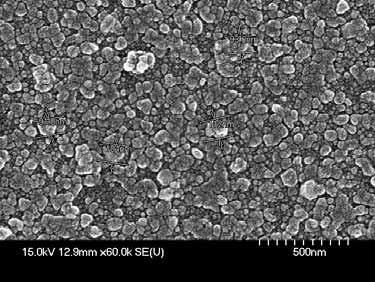


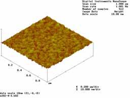
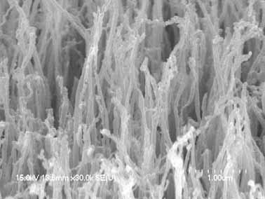
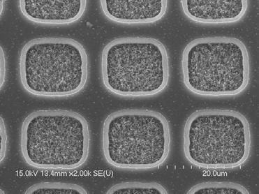
16 (a) (b) (d) 57
17 Nano-particle sizes CNTs length 40 Nano-particle sizes Catalyst metal thickness (e) CNTs length Catalyst metal Nano-particle CNTs length thickness sizes (f) Fig. 4.1 Effects of pretreatment 15min for different catalyst layer thickness (a) 50Å, (b) 75Å, (c) 100Å, (d) 150Å, (e) plot of average nanoparticle size and CNT length as a function the Fe-Ni thickness (pretreatment temperature 700 ), and (f) catalyst metal thickness versus nanoparticle size and CNT lengths. 58

(C 2 H 4 =20sccm, 500,")
(C 2 H 4 =20sccm, 700,")
18 Fe-Ni Fe-Ni-C (f) (a) (b) (c) (d) Fig. 4.2 Effects of CH 4 on pre-treatment for CNT growth (a) without CH 4, (b) with CH 4 (200sccm)(C 2 H 4 =20sccm, 500, 15minutes), (c) without CH 4, (d) with CH 4 (200sccm)(C 2 H 4 =20sccm, 700, 15minutes). 59


19 (a) (b) 60
 without")
 bamboo-like")
20 (c) (d) Fig. 4.3 Effects of CNTs growth (a) without N 2, (b) with N 2, (c) TEM image for bamboo-like CNTs, and (d) bamboo-like CNTs mechanism [74]. 61

 C 2 H")
 C 2 H")
 C 2 H")


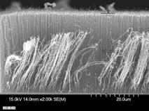
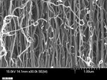
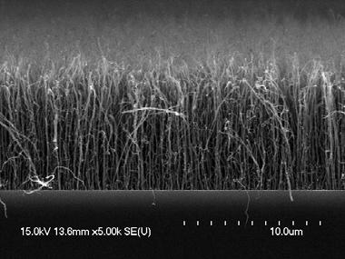
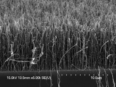
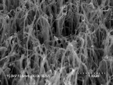
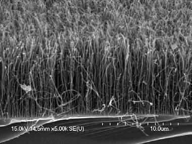
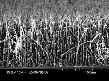
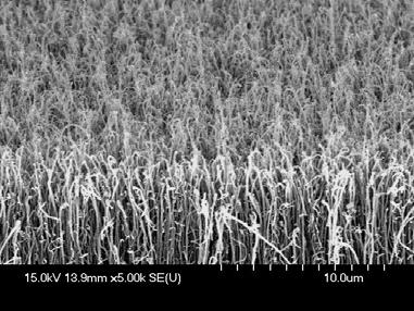
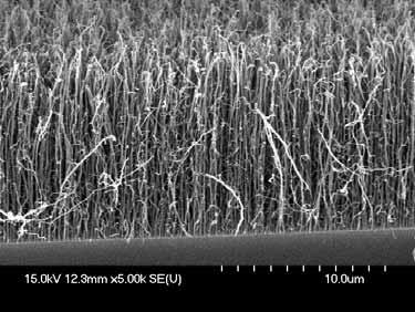
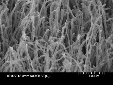
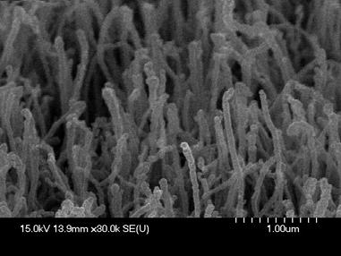
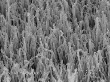
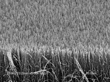
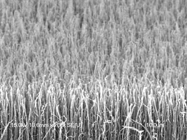
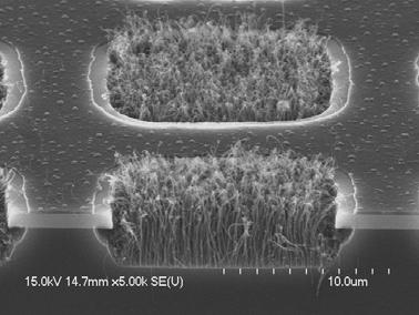
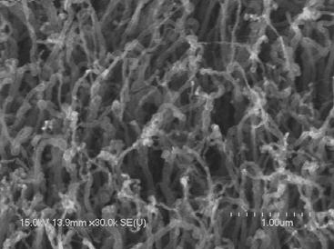
21 (a) C 2 H 4 : 20sccm (b) C 2 H 4 : 50sccm (c) C 2 H 4 : 70sccm (d) C 2 H 4 : 138sccm 62
22 35 30 CNTs Lengths(um) H degrees I degrees J degrees C 2 H 4 (sccm) (e) C 2 H 4 Growth Temperature flows (f) Fig. 4.4 SEM images for different C 2 H 4 flow rate ) 20sccm, (b) 50sccm, (c) 70sccm, (d) 138sccm, (e) effects of different growth temperature versus C 2 H 4 flow rate and (f) summary experimental results for CNT lengths and different growth temperature. 63
 (f) Fig. 4.")

 base growth,")

(e)")
 catalyst")
23 (a) (b) (c) (d) (e) (f) Fig. 4.5 TEM images for growth mechanism on thermal CVD (a) base growth, (b)(c) with/without the catalyst on base growth, (d)(e) tip growth, and (f) catalyst metal inside. 64
24 (a) (b) ions decomposite more radicals Physical and Chemical Etching reactions of radical on the surface byproduct desorption (c) Fig. 4.6 (a) Physical mechanism, (b) chemical mechanism, and (c) combined physical and chemical mechanism. 65
 (d)")


25 (a) (b) (c) (d) 66
 Raman spectra of Ar 10sccm 60sec for different ICP power 250W 300W 400W 500W Intensity(a.u.")
26 F-N Plot : Ar 10sccm 60sec PPT for different ICP power 250W 300W 400W 500W /E (e) Raman spectra of Ar 10sccm 60sec for different ICP power 250W 300W 400W 500W Intensity(a.u.) 250W 300W 400W 500W Wavenumber(cm -1 ) (f) Ar 10sccm 60sec PPT for different ICP power F-N Plot : Ar 10sccm 60sec PPT for different ICP power -8 Emission Current Density(A/cm 2 ) E-3 1E-4 ln(j/e 2 ) 250W 300W 400W 500W ln(j/e 2 ) W 300W 400W 500W -26 1E Application Field(E)(v/um) 1/E (g) (h) Sample number Condition Turn on field E (V/um) (@J=10uA/cm 2 ) Current density J (ma/cm 2 ) (@E=5 v/um) Field enhancement factor (ß) a. As-grown b. 250W c. 300W d. 400W e. 500W (i) Fig. 4.7 SEM images of CNTs post-treatment by Ar 10sccm 60sec for different ICP power of (a), (b) 250W, (c) 300W, (d) 400W, (e) 500W, (f ) Raman spectra of CNTs, (g) field emission curve J-E, (h) F-N plot, and (i) summary experimental results. 67
 (d)")


27 (a) (b) (c) (d) 68
 Raman spectra of Ar 20sccm 60sec for different ICP power 250W 300W 400W 500W Intensity(a.u.")
 0.1 0.01 1E-3 1E-4 ln(j/e2) as-growth 250W 300W 400W 500W ln(j/e2) -10-12 -14-16 -18-20 -22-24 as-growth 250W 300W 400W 500W 1E-5 0 1 2 3 4 5 6 7 Application Field E (v/um) -26 0.")
28 F-N Plot : Ar 20sccm 60sec PPT for different ICP power as-growth 250W 300W 400W 500W /E (e) Raman spectra of Ar 20sccm 60sec for different ICP power 250W 300W 400W 500W Intensity(a.u.) 250W 300W 400W 500W Wavenumber(cm -1 ) (f) Ar 20sccm 60sec PPT for different ICP power -8 F-N Plot : Ar 20sccm 60sec PPT for different ICP power Emission Current Density J (A/cm 2 ) E-3 1E-4 ln(j/e2) as-growth 250W 300W 400W 500W ln(j/e2) as-growth 250W 300W 400W 500W 1E Application Field E (v/um) /E (g) (h) Sample number Condition Turn on field E (V/um) (@J=10uA/cm 2 ) Current density J (ma/cm 2 ) (@E=5 v/um) Field enhancement factor (ß) a. As-grown b. 250W c. 300W d. 400W e. 500W (i) Fig. 4.8 SEM images of CNTs post-treatment by Ar 20sccm 60sec for different ICP power of (a), (b) 250W, (c) 300W, (d) 400W, (e) 500W, (f ) Raman spectra of CNTs, (g) field emission curve J-E, (h) F-N plot, and (i) summary experimental results. 69
 (d)")


29 (a) (b) (c) (d) 70
 Ar 30sccm 60sec PPT for different ICP power F-N Plot : Ar 30sccm 60sec PPT for different ICP power -8 F-N Plot : Ar 30sccm 60sec PPT for different ICP power Emission Current Density J (A/cm 2 )")
 (g) Sample number Condition Turn on field E (V/um) (@J=10uA/cm 2 ) Current density J (ma/cm 2 ) (@E=5 v/um) Field enhancement factor (ß) a. As-grown 3.1 2.35 1869 b. 250W 3.23 1.")
30 (e) Ar 30sccm 60sec PPT for different ICP power F-N Plot : Ar 30sccm 60sec PPT for different ICP power -8 F-N Plot : Ar 30sccm 60sec PPT for different ICP power Emission Current Density J (A/cm 2 ) E-3 1E-4 1E-5 ln(j/e 2 ) 250W 300W 400W 500W 1/E 250W 300W 400W 500W Application Field E (v/um) ln(j/e 2 ) W 300W 400W 500W /E (f) (g) Sample number Condition Turn on field E (V/um) (@J=10uA/cm 2 ) Current density J (ma/cm 2 ) (@E=5 v/um) Field enhancement factor (ß) a. As-grown b. 250W c. 300W d. 400W e. 500W (h) Fig. 4.9 SEM images of CNTs post-treatment by Ar 30sccm 60sec for different ICP power of (a), (b) 250W, (c) 300W, (d) 400W, (e) 500W, (f ) field emission curve J-E, (g) F-N plot, and (h) summary experimental results. 71
 (d)")


31 (a) (b) (c) (d) 72
 Ar 40sccm 60sec PPT for different ICP power F-N Plot : Ar 40sccm 60sec PPT for different ICP power -8 F-N Plot : Ar 40sccm 60sec PPT for different ICP power Emission Current Density J (A/cm 2 )")
 (g) Sample number Condition Turn on field E (V/um) (@J=10uA/cm 2 ) Current density J (ma/cm 2 ) (@E=5 v/um) Field enhancement factor (ß) a. As-grown 3.1 2.35 1869 b. 250W 4.35 0.")
32 (e) Ar 40sccm 60sec PPT for different ICP power F-N Plot : Ar 40sccm 60sec PPT for different ICP power -8 F-N Plot : Ar 40sccm 60sec PPT for different ICP power Emission Current Density J (A/cm 2 ) E-3 1E-4 1E-5 ln(j/e 2 ) 250W 300W 400W 500W 1/E 250W 300W 400W 500W Application Field E (v/um) ln(j/e 2 ) W 300W 400W 500W /E (f) (g) Sample number Condition Turn on field E (V/um) (@J=10uA/cm 2 ) Current density J (ma/cm 2 ) (@E=5 v/um) Field enhancement factor (ß) a. As-grown b. 250W c. 300W d. 400W e. 500W (h) Fig SEM images of CNTs post-treatment by Ar 40sccm 60sec for different ICP power of (a), (b) 250W, (c) 300W, (d) 400W, (e) 500W, (f ) field emission curve J-E, (g) F-N plot, and (h) summary experimental results. 73
 (d)")


33 (a) (b) (c) (d) 74
34 Intensity(a.u) Wavenumber(cm -1 ) BIAS 50W BIAS 100W BIAS 150W (e) Ar 20sccm ICP 300W 60sec PPT for different BIAS power F-N Plot : Ar 20sccm ICP 300W 60sec PPT for different BIAS power F-N Plot : Ar 20sccm ICP 300W 60sec PPT for different BIAS power -8 Emission Current Density(A/cm 2 ) E-3 1E-4 ln(j/e 2 ) Bias 0W Bias 50W Bias 100W Bias 150W 1/E Bias 0W Bias 50W Bias 100W Bias 150W ln(j/e 2 ) Bias 0W Bias 50W Bias 100W Bias 150W -26 1E Application Field(E)(v/um) 1/E (f) (g) Sample number BIAS Condition Turn on field E (V/um) (@J=10uA/cm 2 ) Current density J (ma/cm 2 ) (@E=5 v/um) Field enhancement factor (ß) (h) Fig SEM images of CNTs post-treatment by Ar 20sccm ICP power 300W 60sec for different BIAS power of (a) 0W, (b) 50W, (c) 100W, (d) 150W, (e) Raman spectra of CNTs, (f) field emission curve J-E, (g) F-N plot, and (h) summary experimental results. 75
 (d)")


35 (a) (b) (c) (d) 76
 60 50 O2 5sccm 250W 60sec O2 5sccm 300W 60sec O2 5sccm 400W 60sec O2 5sccm 500W 60sec Intensity(a.u.")
 0.01 1E-3 1E-4 ln(j/e 2 ) O 2 250W O 2 300W O 2 400W O 2 500W ln(j/e 2 ) -10-12 -14-16 -18-20 -22-24 O 2 250W O 2 300W O 2 400W O 2 500W -26 1E-5 0 1 2 3 4 5 6 7 0.0 0.1 0.2 0.3 0.")
36 F-N Plot : O 2 5sccm 60sec PPT for different ICP power O 2 250W O 2 300W O 2 400W O 2 500W /E (e) O2 5sccm 250W 60sec O2 5sccm 300W 60sec O2 5sccm 400W 60sec O2 5sccm 500W 60sec Intensity(a.u.) Wavenumber(cm -1 ) (f) O 2 5sccm 60sec PPT for different ICP power F-N Plot : O 2 5sccm 60sec PPT for different ICP power -8 Emission Current Density(A/cm 2 ) E-3 1E-4 ln(j/e 2 ) O 2 250W O 2 300W O 2 400W O 2 500W ln(j/e 2 ) O 2 250W O 2 300W O 2 400W O 2 500W -26 1E Application Field(E)(v/um) 1/E (g) (h) Sample number Condition Turn on field E (V/um) (@J=10uA/cm 2 ) Current density J (ma/cm 2 ) (@E=5 v/um) Field enhancement factor (ß) a. As-grown b. 250W c. 300W d. 400W e. 500W (i) Fig SEM images of CNTs post-treatment by O 2 5sccm 60sec for different ICP power of (a), (b) 250W, (c) 300W, (d) 400W, (e) 500W, (f ) Raman spectra of CNTs, (g)field emission curve J-E, (h) F-N plot, and (i) summary experimental results. 77
 (d)")


37 (a) (b) (c) (d) 78
 O 2 10sccm 60sec PPT for different ICP power F-N Plot : O 2 10sccm 60sec PPT for different ICP power -8 F-N Plot : O 2 10sccm 60sec PPT for different ICP power Emission Current Density(A/cm 2 )")

38 (e) O 2 10sccm 60sec PPT for different ICP power F-N Plot : O 2 10sccm 60sec PPT for different ICP power -8 F-N Plot : O 2 10sccm 60sec PPT for different ICP power Emission Current Density(A/cm 2 ) E-3 1E-4 1E-5 ln(j/e 2 ) O 2 250W O 2 300W O 2 400W O 2 500W 1/E O 2 250W O 2 300W O 2 400W O 2 500W Application Field(E)(v/um) ln(j/e 2 ) O 2 250W O 2 300W O 2 400W O 2 500W /E (f) (g) Sample number Condition Turn on field E (V/um) (@J=10uA/cm 2 ) Current density J (ma/cm 2 ) (@E=5 v/um) Field enhancement factor (ß) a. As-grown b. 250W c. 300W d. 400W e. 500W (h) Fig SEM images of CNTs post-treatment by O 2 10sccm 60sec for different ICP power of (a), (b) 250W, (c) 300W, (d) 400W, (e) 500W, (f ) field emission curve J-E, (g) F-N plot, and (h) summary experimental results. 79
 (d)")


39 (a) (b) (c) (d) 80
 O 2 20sccm 60sec PPT for different ICP power F-N Plot : O 2 20sccm 60sec PPT for different ICP power F-N Plot : O 2 20sccm 60sec PPT for different ICP power -8 Emission Current Density(A/cm 2 )")
(v/um) 1/E (f) (g) Sample number Condition Turn on field E (V/um) (@J=10uA/cm 2 ) Current density J (ma/cm 2 ) (@E=5 v/um) Field enhancement factor (ß) a.")
40 (e) O 2 20sccm 60sec PPT for different ICP power F-N Plot : O 2 20sccm 60sec PPT for different ICP power F-N Plot : O 2 20sccm 60sec PPT for different ICP power -8 Emission Current Density(A/cm 2 ) E-3 1E-4 ln(j/e 2 ) O 2 250W O 2 300W O 2 400W O 2 500W 1/E O 2 250W O 2 300W O 2 400W O 2 500W ln(j/e 2 ) O 2 250W O 2 300W O 2 400W O 2 500W -26 1E Application Field(E)(v/um) 1/E (f) (g) Sample number Condition Turn on field E (V/um) (@J=10uA/cm 2 ) Current density J (ma/cm 2 ) (@E=5 v/um) Field enhancement factor (ß) a. As-grown b. 250W c. 300W d. 400W e. 500W (h) Fig SEM images of CNTs post-treatment by O 2 20sccm 60sec for different ICP power of (a), (b) 250W, (c) 300W, (d) 400W, (e) 500W, (f ) field emission curve J-E, (g) F-N plot, (h) summary experimental results. 81
 (d)")


41 (a) (b) (c) (d) 82
42 BIAS 50W BIAS 100W BIAS 150W 240 Intensity(a.u) Wavenumber(cm -1 ) (e) O 2 10sccm ICP 300W 60sec PPT for different BIAS power F-N Plot : O 2 10sccm ICP 300W 60sec PPT for different BIAS power F-N Plot : O 2 10sccm ICP 300W 60sec PPT for different BIAS power -8 Emission Current Density(A/cm 2 ) E-3 1E-4 1E-5 ln(j/e 2 ) BIAS 50W BIAS 100W BIAS 150W 1/E Jorig J50 J100 J Application Field(E)(v/um) ln(j/e 2 ) LNorig1 LN501 LN1001 LN /E (f) (g) Sample number BIAS Condition Turn on field E (V/um) (@J=10uA/cm 2 ) Current density J (ma/cm 2 ) (@E=5 v/um) Field enhancement factor (ß) a. 0W b. 50W c. 100W d. 150W (h) Fig SEM images of CNTs post-treatment by O 2 10sccm ICP power 300W 60sec for different BIAS power of (a) 0W, (b) 50W, (c) 100W, (d) 150W, (e ) Raman spectra of CNTs, (f) field emission curve J-E, (g) F-N plot, and (h) summary experimental results. 83
 84")

43 (a) (b) (c) 84
44 F-N Plot : Ar 20sccm and O 2 10sccm mixture gas without/with Bias power without Bias power with Bias power /E Ar 20sccm and O 2 10sccm mixture gas without/with Bias power F-N Plot : Ar 20sccm and O 2 10sccm mixture gas without/with Bias power -8 Emission Current Density(A/cm 2 ) E-3 1E-4 1E-5 ln(j/e 2 ) without Bias power with Bias power Application Field(E)(v/um) ln(j/e 2 ) without Bias power with Bias power /E (d) (e) Sample number BIAS Condition Turn on field E(V/um) (@J=10uA/cm 2 ) Current density J(mA/cm 2 ) (@E=5 v/um) Field enhancement factor (ß) a. No PPT b. without Bias c. With Bias (f) Fig SEM images of CNTs post-treatment by Ar 20sccm and O 2 10sccm mixture gas ICP power 300W 60sec for BIAS power of (a) no PPT, (b) without Bias power, (c) with Bias power 100W, (d)field emission curve J-E, (e) F-N plot, and (f) summary experimental results. 85
 (d)")


45 (a) (b) (c) (d) 86
46 Ar HDPPT O2 HDPPT Anode current I a (ua) Application gate voltage V g (v) (e) Sample number Condition Turn on voltage Emission Current (ua) (@V=50 v) a. b. Ar (20sccm) O 2 (10sccm) (f) Fig SEM images of CNTs post-treatment for PPT (a) triode structure, (b), (c) Ar 20sccm for ICP power 300W 60sec, (d) O 2 10sccm for ICP power 300W 60sec, (e) field emission curve I-V, and (f) summary field emission results. 87
47 Table 4-1 Comparison physical versus chemical plasma etching. Etch Parameter Etch Mechanism Physical etch (RF field perpendicular to wafer surface) Physical ion sputtering Physical etch (RF field parallel to wafer surface) Radicals in plasma reacting with wafer surface Chemical etch Radical in liquid reacting with wafer surface Combined Physical and Chemical In dry etch, etching includes ion sputtering and radicals reacting with wafer surface Sidewall Profile Anisotropic Isotropic Isotropic Anisotropic to isotropic Selectivity Poor/difficult to Fair/good Good/excellent Fair/good increase Etch Rate High Moderate Low Moderate Table 4-2 Shows effects of changing plasma etch parameters. Increased( ) or Decrease( ) in Etch Control Parameters RF Frequency RF Power DC BIAS Electrode Size Ion Energy DC BIAS Etch Rate Selectivity Physical Etch 88
48 Table 4-3 Summary Ar and O 2 HDPPT for different flow rates VS different ICP Powers on turn-on field, emission current density, and field enhancement factor. ß 89
49 Table 4-4 Summary Ar and O 2 HDPPT for different BIAS Powers on turn-on field, emission current density, and field enhancement factor ß 90
Arcing prevention by dry clean optimization at Shallow Trench Isolation (STI) Etch in AMAT MxP by use of plasma parameters
 Etch in AMAT MxP by use of plasma parameters") Page 1 Arcing prevention by dry clean optimization at Shallow Trench Isolation (STI) Etch in AMAT MxP by use of plasma parameters www.tu-cottbus.de www.infineon.com 2 nd AEC/ Conference Europe, April 18
Page 1 Arcing prevention by dry clean optimization at Shallow Trench Isolation (STI) Etch in AMAT MxP by use of plasma parameters www.tu-cottbus.de www.infineon.com 2 nd AEC/ Conference Europe, April 18
Advanced Technique for Si 1-x Ge x Characterization: Infrared Spectroscopic Ellipsometry
 Advanced Technique for Si 1-x Ge x Characterization: Infrared Spectroscopic Ellipsometry Richard Sun Angstrom Sun Technologies Inc., Acton, MA Joint work with Darwin Enicks, I-Lih Teng, Janice Rubino ATMEL,
Sputter System. SPS-R2R series. ULTECH Co., Ltd.
 Sputter System SPS-R2R series Introduction System Picture (reference) Process 1) Application : 2) Sputtering material : TCO (ITO,AZO,ZnO), Metal 3) Film width : max. 100mm 4) Film length : max. 100M 4)
This chapter gives details of the design, development, and characterization of the
 CHAPTER 5 Electromagnet and its Power Supply This chapter gives details of the design, development, and characterization of the electromagnets used to produce desired magnetic field to confine the plasma,
Sundar Mayavan Lead Acid Battery Group CSIR- Central Electrochemical Research Institute Karaikudi, INDIA. 22/9/ th Asian Battery Conference 1
 Influence of Carbon Nanotubes, Glycine, Boron-Carbon- Nitride and Molybdenum disulfide as Negative-Plate Additives on the Performance of Lead Acid Batteries Sundar Mayavan Lead Acid Battery Group CSIR-
STUDY OF HIGH ENERGY CATHODE MATERIALS : LI-RICH MATERIALS
 STUDY OF HIGH ENERGY CATHODE MATERIALS : LI-RICH MATERIALS Jean-François Colin, A. Boulineau, L. Simonin, D. Peralta, C. Bourbon, F. Fabre CEA LITEN DEHT October 28 th, 2014 MATERIALS FOR POSITIVE ELECTRODE
Rechargeable Batteries
 Nanomaterial approaches to enhance lithium ion batteries Potential Environmental Benefits of Nanotechnology: Fostering Safe Innovation-Led Growth July 17 th, 2009 Brian J. Landi Assistant Professor of
Our Solutions for Automotive.
 Our Solutions for Automotive www.horiba.com info.sci@horiba.com Solutions for Automotive Your Lab Partner Analytical examples of all vehicle parts We support new material developments required for next-generation
Collection of diesel exhaust particle using electrostatic charging prior to mechanical filtration
 Collection of diesel exhaust particle using electrostatic charging prior to mechanical filtration H. Hayashi, M. Kimura, K. Kawahara, Y. Takasaki, K. Takashima and A. Mizuno Abstract After treatment systems
REPORT DOCUMENTATION PAGE
 REPORT DOCUMENTATION PAGE Form Approved OMB No. 0704-0188 Public reporting burden for this collection of information is estimated to average 1 hour per response, including the time for reviewing instructions,
HIGH TEMPERATURE ULTRA HIGH VOLTAGE SIC THYRISTORS
 HIGH TEMPERATURE ULTRA HIGH VOLTAGE SIC THYRISTORS R. Singh, S. Creamer, E. Lieser, S. Jeliazkov, S. Sundaresan GeneSiC Semiconductor Inc. 43670 Trade Center Place, Suite 155, Dulles, VA 20166, USA. Email:
innovation at work The NanoSafe Battery Alan J. Gotcher, PhD President & CEO Altair Nanotechnologies, Inc. November 29 th, 2006 Research Manufacturing
 Research The NanoSafe Battery Manufacturing Alan J. Gotcher, PhD President & CEO Altair Nanotechnologies, Inc. November 29 th, 2006 Products Partners With the exception of historical information, matters
Ion Energy Distribution Measurements Past, Present and Future
 Ion Energy Distribution Measurements Past, Present and Future (*Focus on Retarding Field Analyser Technology*) David Gahan CTO S. Sharma PhD candidate, Mike Hopkins CEO Talk Outline Past Present Future
Index. bulk micromachining 2 3, 56, 94 96, 109, 193, 248
 Index ablation 82, 84 accelerometer manufacturers 197, 220 accelerometers 2 4, 7, 9, 126 27, 168 69, 179, 197, 200 1, 204, 210, 212 14, 216 20, 239 41, 249 51, 279 80 digital 200 single-axis 197 98 single-die
Proposal to establish a laboratory for combustion studies
 Proposal to establish a laboratory for combustion studies Jayr de Amorim Filho Brazilian Bioethanol Science and Technology Laboratory SCRE Single Cylinder Research Engine Laboratory OUTLINE Requirements,
High Energy Rechargeable Li-S Battery Development at Sion Power and BASF
 High Energy Rechargeable Li-S Battery Development at Sion Power and BASF Y. Mikhaylik*, C. Scordilis-Kelley*, M. Safont*, M. Laramie*, R. Schmidt**, H. Schneider**, K. Leitner** *Sion Power Corporation,
Development of Micro Fuel Cells with help of MEMS Technologies
 MINATEC 2003 Development of Micro Fuel Cells with help of MEMS Technologies, Stefan Wagner, Herbert Reichl, Fraunhofer IZM, 13355 Berlin, Germany, Tel. +49 30 314 72 833, hahn@izm.fhg.de Michael Krumm,
Requirement, Design, and Challenges in Inorganic Solid State Batteries
 Requirement, Design, and Challenges in Inorganic Solid State Batteries Venkat Anandan Energy Storage Research Department 1 Ford s Electrified Vehicle Line-up HEV Hybrid Electric Vehicle C-Max Hybrid Fusion
Model Comparison with Experiments. 341 N. Science Park Road State College, PA U.S.A.
 Model Comparison with Experiments 41 N. Science Park Road State College, PA 168 U.S.A. www.ecpowergroup.com AutoLion TM : Unprecedented Accuracy in Capturing Liion Battery Performance Voltage (V) Temperature
Thermal Battery Development Reduced Product Variability Through Six Sigma and Materials Finger-Printing
 Power Sources Center 50 th Annual NDIA Fuze Conference Norfolk, VA 9-11 May 2006 Thermal Battery Development Reduced Product Variability Through Six Sigma and Materials Finger-Printing Authors: Paul F.
Silicon Carbide Semiconductor Products
 Power Matters Silicon Carbide Semiconductor Products Low Switching Losses Low Gate Resistance High Power Density High Thermal Conductivity High Avalanche (UIS) Rating Reduced Heat Sink Requirements High
Development of Micro Cogeneration System with a Porous Catalyst Microcombustor
 PowerMEMS214 Awaji, Japan 1/2 Development of Micro Cogeneration System with a Porous Catalyst Microcombustor Shuhei Takahashi, Masateru Tanaka, Naoya Ieda and Tadayoshi Ihara Dept. Mechanical Engineering,
FLUORESCENT INDUCTION
 FLUORESCENT INDUCTION Electrodeless Lamp OPENING NEW FRONTIERS FOR LIGHTING IT IS IMPOSSIBLE TO IMAGINE MODERN LIFE WITHOUT ELECTRIC LIGHTING. WITH THE WIDE AVAILABILITY AND AFFORDABILITY OF TODAY S LIGHTING,
DEPOSITION STAGES. Section 11. Introduction to the EpiCentre range of deposition stages 150. Technology Advantages 152
 Section DEPOSITION STAGES Introduction to the EpiCentre range of deposition stages 150 Technology Advantages 152 EC-I In-line deposition stage 154 EC-R Right angle deposition stage 158 GLAD Glancing Angle
CHAPTER 2 LITERATURE REVIEW AND SCOPE OF THE PRESENT STUDY
 57 CHAPTER 2 LITERATURE REVIEW AND SCOPE OF THE PRESENT STUDY 2.1 LITERATURE REVIEW Biodiesel have been processed from various plant derived oil sources including both Edible and Non-Edible oils. But,
Impact of Vehicle-to-Grid (V2G) on Battery Life
 on Battery Life") Impact of Vehicle-to-Grid (V2G) on Battery Life The Importance of Accurate Models David Howey, Jorn Reniers, Grietus Mulder, Sina Ober-Blöbaum Department of Engineering Science, University of Oxford EnergyVille,
Impact of Vehicle-to-Grid (V2G) on Battery Life The Importance of Accurate Models David Howey, Jorn Reniers, Grietus Mulder, Sina Ober-Blöbaum Department of Engineering Science, University of Oxford EnergyVille,
UN/SCETDG/47/INF.13/Rev.1
 Committee of Experts on the Transport of Dangerous Goods and on the Globally Harmonized System of Classification and Labelling of Chemicals New proper shipping name for rechargeable lithium metal batteries
HERCULES-2 Project. Deliverable: D8.8
 HERCULES-2 Project Fuel Flexible, Near Zero Emissions, Adaptive Performance Marine Engine Deliverable: D8.8 Study an alternative urea decomposition and mixer / SCR configuration and / or study in extended
EFFECT OF INJECTION ORIENTATION ON EXHAUST EMISSIONS IN A DI DIESEL ENGINE: THROUGH CFD SIMULATION
 EFFECT OF INJECTION ORIENTATION ON EXHAUST EMISSIONS IN A DI DIESEL ENGINE: THROUGH CFD SIMULATION *P. Manoj Kumar 1, V. Pandurangadu 2, V.V. Pratibha Bharathi 3 and V.V. Naga Deepthi 4 1 Department of
APPLIED ELECTROCHEMISTRY Technion s Chemical Power Sources Research
 ה ט כ נ י ו ן מ כ ו ן ט כ נ ו ל ו ג י ל י ש ר א ל TECHNION - ISRAEL INSTITUTE OF TECHNOLOGY הפקולטה למדע והנדסה של חומרים DEPARTMENT OF MATERIALS SCIENCE & ENGINEERING - APPLIED ELECTROCHEMISTRY Technion
New proper shipping name for rechargeable lithium metal batteries
 Committee of Experts on the Transport of Dangerous Goods and on the Globally Harmonized System of Classification and Labelling of Chemicals New proper shipping name for rechargeable lithium metal batteries
NEW DESIGN CONCEPTS FOR HIGH-CAPACITY BATTERY MATERIALS
 NEW DESIGN CONCEPTS FOR HIGH-CAPACITY BATTERY MATERIALS CARSTEN STREB INSTITUTE OF INORGANIC CHEMISTRY I ULM UNIVERSITY CARSTEN.STREB@UNI-ULM.DE WWW.STREBGROUP.NET WORLD MOBILITY SUMMIT 2016 OCTOBER 20TH
Influence of fuel properties and aftertreatment techn. on particles in tailpipe and ambient air
 M. Gruber 43 TU Wien Austria Influence of fuel properties and aftertreatment techn. on particles in tailpipe and ambient air - 1-4. ETH Conference on Nanoparticle Measurement, Zurich, 2000-08-08 Comparative
Energy Materials: Meeting the Challenge 9 th October 2008
 Intelligent Energy Holdings Energy Materials: Meeting the Challenge 9 th October 2008 PEM Fuel Cells Paul Adcock Clean Fuel and Power 2008 Intelligent Energy Limited The information in this document is
A Particulate Matter Sensor with Groove Electrode for Real-Time Diesel Engine On-Board Diagnostics
 Journal of Sensor Science and Technology Vol. 22, No. 3 (2013) pp. 191-196 http://dx.doi.org/10.5369/jsst.2013.22.3.191 pissn 1225-5475/eISSN 2093-7563 A Particulate Matter Sensor with Groove Electrode
A Micro Power Generation System with Gas Turbine Engine and Piezo Converter -- Modeling, Fabrication and Characterization --
 A Micro Power Generation System with Gas Turbine Engine and Piezo Converter -- Modeling, Fabrication and Characterization -- X.C. Shan *1, Z.F. Wang 1, Y.F. Jin 1, C.K. Wong 1, J. Hua 2, M. Wu 2, F. Lu
CHA-50 Evaporator Operation
 CHA-50 Evaporator Operation Roger Robbins 7/8/2009 John Maynard The University of Texas at Dallas ERIK JONSSON SCHOOL OF ENGINEERING AUTHORS: Roger Robbins, John Maynard Page 1 of 18 CHA-50 Evaporator
INDIAN INSTITUTE OF TECHNOLOGY KANPUR Kanpur , Uttar Pradesh, India Centre for Lasers and Photonics
 INDIAN INSTITUTE OF TECHNOLOGY KANPUR Kanpur 208016, Uttar Pradesh, India Centre for Lasers and Photonics Enquiry no.: CELP/RV/EQP/MHR/2017/1 Enquiry date: 23/04/2018 Closing date: 17/05/2018 Sealed quotations
WP8: Engine Integrated SCR and combined DPF and SCR
 Partners LUH: Leibniz University Hannover (Hannover) DTU: Technical University of Denmark (Copenhagen) MDT-CPH: MAN Diesel & Turbo, Marine Two-Stroke (Copenhagen) MDT-AUG: MAN Diesel & Turbo, Marine Four-Stroke
From materials to vehicle what, why, and how? From vehicle to materials
 From materials to vehicle what, why, and how? From vehicle to materials Helena Berg Outline 1. Electric vehicles and requirements 2. Battery packs for vehicles 3. Cell selection 4. Material requirements
I. Equivalent Circuit Models Lecture 3: Electrochemical Energy Storage
 I. Equivalent Circuit Models Lecture 3: Electrochemical Energy Storage MIT Student In this lecture, we will learn some examples of electrochemical energy storage. A general idea of electrochemical energy
Case study on Selective catalytic reduction(scr) performance improvement over legislative engine cycles using 1D simulation
 performance improvement over legislative engine cycles using 1D simulation") Case study on Selective catalytic reduction(scr) performance improvement over legislative engine cycles using 1D simulation Presented by Mohak Samant & Hitesh Chaudhari Under the guidance of Dr. N. H.
Case study on Selective catalytic reduction(scr) performance improvement over legislative engine cycles using 1D simulation Presented by Mohak Samant & Hitesh Chaudhari Under the guidance of Dr. N. H.
Energy Storage. Chm446/1304 April 2, 2014 Hand your assignments in at the front.
 Energy Storage Chm446/1304 April 2, 2014 Hand your assignments in at the front http://www.youtube.com/watch?v=dtqsiplgxa&feature=youtu.be World Energy Needs Projected to Increase 53% From 2008 to 2035
Development of battery materials with world s highest performance
 Tokyo University of Agriculture and Technology Nippon Chemi-Con Corporation May 6, 2010 Applying nano-hybrid technology to the next generation lithium-ion battery Development of battery materials with
3300mAh Zinc-Air Batteries for Portable Consumer Products
 3300mAh Zinc-Air Batteries for Portable Consumer Products Binyamin Koretz Dr. Neal Naimer Menachem Givon Electric Fuel Limited www.electric-fuel.com Background Electric Fuel Ltd. is the world leader in
KH SWCNT. High Quality in Mass Quantity for Industrial Use
 KH SWCNT High Quality in Mass Quantity for Industrial Use Blueprint to the Future! KH Chemicals Co., Ltd. is a company specialized in production of high quality SWCNT (Single-Walled Carbon Nanotubes) and
User Manual for the RAMK Rotational Absolute Magnetic Kit Encoder
 VISHAY MCB www.vishay.com Variable Resistors By Frederic Bourget and Emmanuel Lemelle INTRODUCTION The purpose of this user manual is to define the precautions for unpacking, mounting, and using RAMK encoder
UPGRADE OF AN INDUSTRIAL Al-BSF SOLAR CELL LINE INTO PERC USING SPATIAL ALD Al 2 O 3
 UPGRADE OF AN INDUSTRIAL SOLAR CELL LINE INTO USING SPATIAL ALD Al 2 O 3 Floor Souren, Xavier Gay, Bas Dielissen and Roger Görtzen SoLayTec, Dillenburgstraat 9G, 5652 AM, Eindhoven, The Netherlands e-mail
Electricity Simulation: Sound
 Electricity Simulation: Sound Activity One Introduction How do telephones and radios send sound so that we hear it? When anything vibrates, it produces sound. When sounds enter a microphone, the sound
Influence of Bio-Syngas Contaminants on SOFC
 Influence of Bio-Syngas Contaminants on SOFC BioCellus & Green Fuel Cell Bert Rietveld, Nico Dekker, Jan Pieter Ouweltjes www.ecn.nl Introduction A Solid Oxide Fuel Cell converts H 2 directly in electricity
STUDIES OF NITROUS OXIDE CONVERSION IN GLIDING ARC DISCHARGES
 STUDIES OF NITROUS OXIDE CONVERSION IN GLIDING RC DISCHRGES K. Krawczyk a, and M. Wieczorkowski Warsaw University of Technology, Faculty of Chemistry, ul. Noakowskiego 3, -664 Warszawa, POLND bstract.
Available online Research Article
 Available online www.jocpr.com Journal of Chemical and Pharmaceutical Research, 2016, 8(3):246-257 Research Article ISSN : 0975-7384 CODEN(USA) : JCPRC5 Investigation on aluminium oxide nano particles
The study of an electric spark for igniting a fuel mixture
 21, 12th International Conference on Optimization of Electrical and Electronic Equipment, OPTIM 21 The study of an electric spark for igniting a fuel mixture B Hnatiuc*, S Pellerin**, E Hnatiuc*, R Burlica*
6 Watt Segmented Power Generator Modules using Bi 2 Te 3 and (InGaAs) 1-x (InAlAs) x Elements Embedded with ErAs Nanoparticles.
 1-x (InAlAs) x Elements Embedded with ErAs Nanoparticles.") Mater. Res. Soc. Symp. Proc. Vol. 1129 2009 Materials Research Society 1129-V08-04 6 Watt Segmented Power Generator Modules using Bi 2 Te 3 and (InGaAs) 1-x (InAlAs) x Elements Embedded with ErAs Nanoparticles.
Mater. Res. Soc. Symp. Proc. Vol. 1129 2009 Materials Research Society 1129-V08-04 6 Watt Segmented Power Generator Modules using Bi 2 Te 3 and (InGaAs) 1-x (InAlAs) x Elements Embedded with ErAs Nanoparticles.
Segmented rechargeable micro battery for wearable applications based on printed separator and LTO/NMC electrodes
 Segmented rechargeable micro battery for wearable applications based on printed separator and LTO/NMC electrodes Robert Hahn 1 M. Ferch 2, M. Hubl 3, M. Molnar 1, K. Marquardt 2, K. Hoeppner 2, M. Luecking
3.2 The alkanes. Isomerism: Alkanes with 4 or more carbons show a type of structural isomerism called chain isomerism
 3.2 The alkanes Prior knowledge: Types of formula general, empirical, molecular, structural, displayed and skeletal. Nomenclature Structural isomers chain and position isomers Free radicals Aliphatic Alkanes
,!-"#ASCU 3 V TFT KUP / T/.,- * 5+47 =SBU>9L "# $& '% "#,!-"#ASCU,- M?OUP.
 TFT2010.10.21 OJT OJT A B C 8 10 I 12006.6.1 2008.3.31 NIPPON GOHSEI : 2 : 2008.4.1~2010.3.31 Why flexible solar cells? Reduction of weight and volume: Easy installation, reduction of cost for
ITATION PAGE. one. I ELECTc 2p ",iawini q?fj
 MASTER COPT AD-A244 110 KEEP THIS COPY F.OR REPRODUCTION PURPOSES ITATION PAGE Form Approved 0M8 NO. 07044189 *) to «««ft?«1 *Ou/ Of* mpqm0. nc'uamq tn«time for revi«v*irtq imtructiom. seifcficnq i)ti»9
United States Patent (19) Kim et al.
 Kim et al.") United States Patent (19) Kim et al. 54 METHOD OF AND APPARATUS FOR COATING AWAFER WITH A MINIMAL LAYER OF PHOTORESIST 75 Inventors: Moon-woo Kim, Kyungki-do; Byung-joo Youn, Seoul, both of Rep. of Korea
United States Patent (19) Kim et al. 54 METHOD OF AND APPARATUS FOR COATING AWAFER WITH A MINIMAL LAYER OF PHOTORESIST 75 Inventors: Moon-woo Kim, Kyungki-do; Byung-joo Youn, Seoul, both of Rep. of Korea
Development of high reliability fuse for space use
 The26th Microelectronics Workshop 1 Development of high reliability fuse for space use TATEYAMA KAGAKU DEVICE TECHNOLOGY CO.,LTD http://www.tateyama.jp/ CONTENTS 2 1. Background 2. Development of SMD Fuse
Carbon Nanotubes, Nanorods, and Nanoparticles from Engines
 Carbon Nanotubes, Nanorods, and Nanoparticles from Engines David Kittelson TE Murphy Engine Research Laboratory Department of Mechanical Engineering University of Minnesota 20th ETH Conference on Combustion
FACETS OF GRAPHITE. June 2017
 FACETS OF GRAPHITE June 2017 1. INTRODUCTION What is Graphite? Why is Graphite Important? Current Demand & Prices for Selected High Purity Graphite Applications Contents 2. SELECTED APPLICATIONS Lithium
U.S. DOE Perspective on Lithium-ion Battery Safety
 U.S. DOE Perspective on Lithium-ion Battery Safety David Howell US Department of Energy Washington, DC Technical Symposium: Safety Considerations for EVs powered by Li-ion Batteries The National Highway
Normal vs Abnormal Combustion in SI engine. SI Combustion. Turbulent Combustion
 Turbulent Combustion The motion of the charge in the engine cylinder is always turbulent, when it is reached by the flame front. The charge motion is usually composed by large vortexes, whose length scales
BATTERIES & SUPERCAPS POST MORTEM ANALYSIS PLATFORM EXTERNAL SERVICES
 BATTERIES & SUPERCAPS POST MORTEM ANALYSIS PLATFORM EXTERNAL SERVICES CONTEXT Over the last years a remarkable evolution has taken place by the introduction of new batteries & supercapacitors technologies
SiGe/Si SUPERLATTICE COOLERS
 SiGe/Si SUPERLATTICE COOLERS Xiaofeng Fan, Gehong Zeng, Edward Croke a), Gerry Robinson, Chris LaBounty, Ali Shakouri b), and John E. Bowers Department of Electrical and Computer Engineering University
2018 HORIBA, Ltd. All rights reserved. 1
 2018 HORIBA, Ltd. All rights reserved. 1 HORIBA Scientific Particle Characterization Dr. Anderson Bonon Key Points to Achieving Successful Laser Diffraction Method Development September 26, 2018 2018 HORIBA,
Influence of shot peening and superfinishing on gears as a repair tool of damaged faces of teeth generated by overheating when grinding.
 Influence of shot peening and superfinishing on gears as a repair tool of damaged faces of teeth generated by overheating when grinding. J. Kritzler Metal Improvement Company, LLC.; Unna, Germany Abstract
B. von Rotz, A. Schmid, S. Hensel, K. Herrmann, K. Boulouchos. WinGD/PSI, 10/06/2016, CIMAC Congress 2016 / B. von Rotz
 Comparative Investigation of Spray Formation, Ignition and Combustion for LFO and HFO at Conditions relevant for Large 2-Stroke Marine Diesel Engine Combustion Systems B. von Rotz, A. Schmid, S. Hensel,
Exercise 3. Battery Charging Fundamentals EXERCISE OBJECTIVE DISCUSSION OUTLINE DISCUSSION. Charging fundamentals
 Exercise 3 Battery Charging Fundamentals EXERCISE OBJECTIVE When you have completed this exercise, you will be familiar with the effects of charge input, charge rate, and ambient temperature on the voltage
COMBUSTION AND EXHAUST EMISSION IN COMPRESSION IGNITION ENGINES WITH DUAL- FUEL SYSTEM
 COMBUSTION AND EXHAUST EMISSION IN COMPRESSION IGNITION ENGINES WITH DUAL- FUEL SYSTEM WLADYSLAW MITIANIEC CRACOW UNIVERSITY OF TECHNOLOGY ENGINE-EXPO 2008 OPEN TECHNOLOGY FORUM STUTTGAT, 7 MAY 2008 APPLICATIONS
Series 347. Granville-Phillips Series 347 Stabil-Ion Vacuum Gauge Module. Instruction Manual
 Series 347 Granville-Phillips Series 347 Stabil-Ion Vacuum Gauge Module Instruction Manual Instruction manual part number 347011 Revision B November 2016 1 Series 316 Series 347 Granville-Phillips Series
Progress in Materials Development and Production for Zero Emissions Powertrains
 Progress in Materials Development and Production for Zero Emissions Powertrains Dr Peter Gray 24 February, 2016 Overview 01 Johnson Matthey Plc 02 JM Activities in Low and Zero Emissions Vehicles 03 Fuel
AUTOMOTIVE TESTING AND OPTIMIZATION. Tools for designing tomorrow's vehicles
 AUTOMOTIVE TESTING AND OPTIMIZATION Tools for designing tomorrow's vehicles 2 Measurement of flow around the side mirror by Particle Image Velocimetry (PIV). Courtesy of Visteon Deutschland GmbH Our advanced
PSIM Tutorial. How to Use Lithium-Ion Battery Model
 PSIM Tutorial How to Use Lithium-Ion Battery Model - 1 - www.powersimtech.com This tutorial describes how to use the lithium-ion battery model. Some of the battery parameters can be obtained from manufacturer
The Rotating Anode X-Ray Tube
 The Rotating Anode X-Ray Tube The rotating Anode tube assemble is a complex piece of electro-mechanical engineering comprising of around 350 parts taking 150 assembly operations and can cost as much as
PIV ON THE FLOW IN A CATALYTIC CONVERTER
 PIV ON THE FLOW IN A CATALYTIC CONVERTER APPLICATION NOTE PIV-016 The study and optimization of the flow of exhaust through a catalytic converter is an area of research due to its potential in increasing
Business and Market Update
 Business and Market Update Dr. Bastian Marheineke Dr. Bastian Marheineke Vice President Sales AIXTRON IC-MOVPE User Meeting Nevada, USA May 26, 2010 AIXTRON Global Presence AIXTRON Inc., Sunnyvale AIXTRON
Improving car environmental and operational characteristics using a multifunctional fuel additive
 Air Pollution XIX 373 Improving car environmental and operational characteristics using a multifunctional fuel additive E. Magaril Department of Economics and Organization of Chemical Industries, Ural
Battery Power for All-Electric Road Vehicles John B. Goodenough and M. Helena Braga The University of Texas at Austin, and of Porto, Portugal
 Battery Power for All-Electric Road Vehicles John B. Goodenough and M. Helena Braga The University of Texas at Austin, and of Porto, Portugal Modern Society runs on the energy stored in fossil fuels. This
Coking and Thermal Process, Delayed Coking
 Coking and Thermal Process, Delayed Coking Fig:4.1 Simplified Refinery Flow Diagram [1,2] Treatment processes : To prepare hydrocarbon streams for additional processing and to prepare finished products.
Journal of KONES Powertrain and Transport, Vol. 21, No ISSN: e-issn: ICID: DOI: /
 Journal of KONES Powertrain and Transport, Vol. 1, No. 1 ISSN: 131- e-issn: 3-133 ICID: 1131 DOI: 1./131.1131 JET FUELS DIVERSITY Air Force Institute of Technology Ksiecia Boleslawa Street, 1-9 Warsaw,
Combustion Properties of Alternative Liquid Fuels
 1. Prologue Combustion Properties of Alternative Liquid Fuels 21 JULY 211 Cheng Tung Chong, Simone Hochgreb Content 1. Introduction 2. What s biodiesels 3. Burner design and experimental 4. Results - Flame
Modeling of Battery Systems and Installations for Automotive Applications
 Modeling of Battery Systems and Installations for Automotive Applications Richard Johns, Automotive Director, CD-adapco Robert Spotnitz, President, Battery Design Predicted Growth in HEV/EV Vehicles Source:
Short Communication In-situ Monitoring of Temperature and Voltage in Lithium-Ion Battery by Embedded Flexible Micro Temperature and Voltage Sensor
 Int. J. Electrochem. Sci., 8 (2013) 2968-2976 International Journal of ELECTROCHEMICAL SCIENCE www.electrochemsci.org Short Communication In-situ Monitoring of Temperature and Voltage in Lithium-Ion Battery
Module 3: Influence of Engine Design and Operating Parameters on Emissions Lecture 14:Effect of SI Engine Design and Operating Variables on Emissions
 Module 3: Influence of Engine Design and Operating Parameters on Emissions Effect of SI Engine Design and Operating Variables on Emissions The Lecture Contains: SI Engine Variables and Emissions Compression
Physics 413, Methods of Experimental Physics. Experiment Q2: Electron e/m ratio
 Physics 413, Methods of Experimental Physics Experiment Q2: Electron e/m ratio Introduction: In this experiment you will determine the ratio of the charge and mass of the electron. This is called the specific
Irradiation facilities at the INFN National Laboratory of Legnaro
 Irradiation facilities at the INFN National Laboratory of Legnaro A. Candelori Istituto Nazionale di Fisica Nucleare and Dipartimento di Fisica, Padova 2/4/2004 OUTLINE The SIRAD irradiation facility at
Noise Reduction in a Reciprocating Compressor by Optimizing the Suction Muffler
 Noise Reduction in a Reciprocating Compressor by Optimizing the Suction Muffler Katakama Nagarjuna ¹ K.Sreenivas² ¹ M.tech student, ²Professor, dept of mechanical engineering kits, markapur, A.P, INDIA
300mm Wafer Electroless Bumping
 300mm Wafer Electroless Bumping T. Teutsch, E. Zakel, T. Oppert Internepcon 2005 January 19, 2005 Tokyo Big Sight, Japan Pac Tech GmbH Outline Short Company Profile Introduction Electroless Ni/Au Under
Energy Storage Technology Roadmap Lithium Ion Technologies
 Energy, Mining and Environment Portfolio Energy Storage Technology Roadmap Lithium Ion Technologies Isobel Davidson, Principal Research Officer 19 November 2014 Energy Storage Technology Roadmap Li ion
Propulsion Solutions for CubeSats and Applications
 Propulsion Solutions for CubeSats and Applications Dr. Dan Williams Director of Business Development Busek Co. Inc. Natick, MA 12 August 2012 CubeSat Developers Workshop Logan, Utah 1 Introduction Satellites
Effects of Bio-coal Briquette Shape on Transport Phenomena in a Curing Unit by CFD Technique M. H. Narasingha*, K.
 Effects of Bio-coal Briquette Shape on Transport Phenomena in a Curing Unit by CFD Technique M. H. Narasingha*, K. Pana-Suppamassadu Department of Chemical Engineering, King Mongkut s University of Technology
Diesel PM collection for marine emission using hole-type electrostatic precipitators
 Air Pollution XXII 145 Diesel PM collection for marine emission using hole-type electrostatic precipitators Y. Ehara 1, A. Osako 1, A. Zukeran 2, K. Kawakami 3 & T. Inui 3 1 Tokyo City University, Japan
Altairnano Grid Stability and Transportation Products
 Altairnano Grid Stability and Transportation Products Joe Heinzmann Senior Director Energy Storage Solutions 1 Altairnano Overview Altairnano is an emerging growth company which is developing and commercializing
4.1 Hypersonic flow - Special characteristics
 Module 4 Lectures 19 to 22 Hypersonic Facilities Keywords: Hypersonic flows, high enthalpy flow, real gas effects, high temperature flows, hypersonic shock tunnels, free piston tunnels, plasma arc tunnels,
Development of a Plasma Etch Insitu Chamber Clean (ICC) and Analysis of Etch Plasma Problems using a SEERS Plasma Sensor
 and Analysis of Etch Plasma Problems using a SEERS Plasma Sensor") Development of a Plasma Etch Insitu Chamber Clean (ICC) and Analysis of Etch Plasma Problems using a SEERS Plasma Sensor Rupert Wagner 1, H. Richter 1, E. Chasanoglou 1, M. Klick 2 1 Texas Instruments
Development of a Plasma Etch Insitu Chamber Clean (ICC) and Analysis of Etch Plasma Problems using a SEERS Plasma Sensor Rupert Wagner 1, H. Richter 1, E. Chasanoglou 1, M. Klick 2 1 Texas Instruments
Electrochemical Energy Storage Devices
 Electrochemical Energy Storage Devices Rajeswari Chandrasekaran, Ph.D. from Energy Storage, Materials & Strategy Research and Advanced Engineering, Ford Motor Company, Dearborn, MI-48124. presented at
Smart Batteries. Smart Battery Management SMBus v1.1. Rev
 Smart Batteries Smart Battery Management SMBus v1.1 1 Rev 1.5 01.12.2014 Smart Battery Packs STANDARD PACKS CUSTOMISED PACKS 2 Hazardous failures of lithium-ion 1. Lithium ions travel through the separator
ZERO PILOT UNITS PIONEERING TECHNOLOGIES ON A SMALL SCALE.
 MY ZERO PILOT UNITS PIONEERING TECHNOLOGIES ON A SMALL SCALE. PILOT UNITS CONTENT Pilot Units... 3 RTO-i-SCR 400... 4 AutoTherm HTR 800... 5 AutoKAT 800... 6 KNV 100... 7 CTU 002... 8 RotorSorb 600...