DuraForce HPR Self-regulating Pump for Open Loop Operation
|
|
|
- Agnes Thompson
- 5 years ago
- Views:
Transcription

1 DuraForce HPR Self-regulating Pump for Open Loop Operation
2 Table of Contents Contents The open loop 4 Specifications and performance 5 Model codes 6 Operational parameters Life time recommendations 8 HPR suction speed 8 Filtration 9 Pressure fluids 10 Eaton LSC-System 11 Noise reduction 12 SPU silencer 12 Torque transmission 14 Mounting flange 15 Drive shaft 17 PTO through drive 18 Output shaft 18 Gear pumps 19 Type of control 22 Load sensing LS 23 LP. LS with hydraulic pressure cut-off 24 TL2. LS with hyperbolic power limitation 25 E1L. LS with electric override 26 Dimensions Single pumps 28 Double pumps back-to-back 29 Multiple pumps 30 Modular system features 32 2 EATON Series HPR Self Regulating Pump E-PUPI-MC008-E2 September 2011

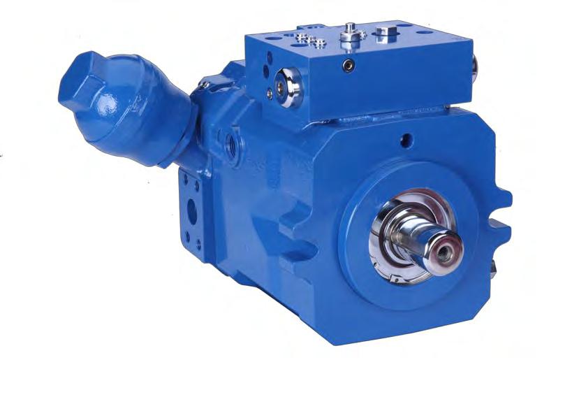
3 1 LS-Regulator Optimum utilisation of power 2 Swash Plate Hydrostatic bearing 3 Piston-Slipper Assembly 21 swash angle 4 Housing Monoshell for high rigidity 5 Valve Plate Housing Highly integrated 6 Actuator Piston Long-lived and precise 7 Through Shaft For additional pumps 8 Cylinder Barrel Compact due to 21 technology 9 Suction Port Good suction capacity also without tank pressurization 10 SPU Reduction of pressure pulsation over the entire range of operation, maintenance-free Design Characteristics High pressure axial piston pump in swash plate design for open loop systems Clockwise or counter clockwise rotation Self-priming at high nominal speed Higher rotating speed by tank pressurization or swash angle reduction Adaptive noise optimization SPU Decompression fluid is drained via pump housing for suction side stability Exact and rugged load sensing controls SAE high pressure ports SAE mounting flange with ANSI or SAE spline shaft Through shaft SAE A, B, B-B, C, D and E Optional tandem and multiple pumps Product Advantages Energy saving operation by flow on demand control Dynamic response Excellent suction up to rated speed Noise optimization over the entire range of operation Optimum interaction with Eaton LSC-Directional Control Valves and LinTronic Compact design High power density High pressure rating High reliability Long working life EATON Series HPR Self Regulating Pump E-PUPI-MC008-E2 September
4 Open Loop Representation of hydraulic components in an open loop circuit: HPR regulating pump with load sensing function for energy saving, flow on demand control and VW load sensing directional control valves for load-independent, synchronous movements of actuators without unintentional interaction. The system is complemented with proven Eaton products such as electronic controls, swing drives and hydraulic motors. Function Diagram Tank B A B B L Filter Cooler L LS HPR R E1L U P T LS P Manifold T Circuit Diagram Tank Filter Cooler L A X U X1 LS2 LS1 P T LS P T HPR R E1L Manifold 4 EATON Series HPR Self Regulating Pump E-PUPI-MC008-E2 September 2011
5 Specifications and Performance The table shows the complete capacity range of the pumps, while the diagram below shows the recommended practical range for the different nominal sizes of the HPR pump with control limit between 200 bar Δp minimum and 280 bar Δp maximum. It enables initial selection of the required nominal pump size. Specifications Model D 165D Rated Size Maximum Displacement cm 3 /rev x105 2x165.6 Speed* min Volume Flow Max. oil flow 1/min Pressure Nominal Pressure bar Peak Pressure bar Permissible Housing Pressure (absolute) bar Input Torque Max. Input torque at max. operating pressure and Vmax Nm Response Times** Vmax -> Vmin swashing at HP 100 bar ms constant max. system pressure HP HP 200 bar ms Vmin -> Vmax swashing from stand-by HP 100 bar ms pressure and zero outlet flow to constant HP 200 bar ms max. system pressure HP Permissible Shaft Loads Axial N Radial N on request on request on request on request on request on request on request on request Perm. Housing Temperature Perm. Housing Temp. with min. perm. viscosity > 10 cst C Weights HPR without oil (approximate) kg Maximum moment of inertia kgm 2 x * Max. operating speed (rated speed) without tank pressurization Operating speed with tank pressurization see chapter operational parameters. ** Measured at fluid viscosity 20 cst and input speed 1500 rpm. Performance Data D Volume Flow [l/min] D Input Speed [rev/min] EATON Series HPR Self Regulating Pump E-PUPI-MC008-E2 September
6 Model Code HPR Self-regulating Pump for Open Loop Operation HPR 105 R 0 S1 M A AC AC AA A 00 A A A Product HPR Open Loop Variable Displacement Pump Displacement cc/r cc/r cc/r cc/r cc/r cc/r cc/r 7 Rotation R CW L CCW 8 Mounting Flange 0 SAE J744 standard (size 105: LP;H1L;E1L only) 1 SAE J744 standard / additional threads (sizes 105; 135; (*u)) 2 SAE J744 standard / additional holes 3 ISO metric (TL2;ETP;LEP only)(*m) 4 plug-in (LP;H1L;E1L only)/ (size 105; (*d)) 5 Bell housing SAE 3 (LP;H1l;E1l only)/(sizes 105; (*d)) 6 Bell housing SAE 4 (LP;H1l;E1l only)/(sizes 105; (*d)) 9 10 Input Driveshaft S1 splined ANSI B /24-14t (SAE C)/(size 105:(*w)) S2 splined ANSI B /24-17t (SAE C-C) S3 splined ANSI B92.1 8/16-13t (SAE D&E) S4 splined ANSI B92.1 8/16-15t (SAE F)/(sizes 210; 280: (*t)) T1 splined ANSI B /32-21t (*t) T2 splined ANSI B /32-23t (*t) T3 splined ANSI B /32-27t (*t) K1 keyed ISO / 40 mm (metric flange only (pos. 8)) K2 keyed ISO / 60 mm 11 Porting M ISO 6149 metric D DIN Pump Control A LP:LS/pressure cut-off B H1L:LS/hydraulic override (*m) C E1L:LS/electric override (*m) D TL2:LS/power limiter (*m)/ (*r) E ETP:electro-proportional/ power limiter/pco (*m)/ (*r) F LEP:LS/electric stroke limiter/pco (*m)/(*r) Pressure Compensator Setting 00 Not applicable (H1L; E1L; TL2) AA 250 bar AB 350 bar AC 420 bar Load Sensing Differential Pressure 00 Not applicable (ETP) AC 20 bar Power Limiter Setting 000 not applicable (LP; H1L; E1L; LEP) value kw (numeric 3 digits) value kw (numeric 3 digits) value kw (numeric 3 digits) value kw (numeric 3 digits) 20 Pressure Limiter Remote Control 0 not applicable (LP; H1L; E1L;TL2) D disabled (ETP; LEP only) R enabled (ETP; LEP only) 21 Power Limiter Remote Control 0 not applicable (LP; H1L; E1L;LEP only) 1 remote power uprating (default for TL2; ETP) 2 remote power up- & downrating (TL2; ETP only) Available Option Preferred Option t Separate Specification Required (*d) DIN porting only (see position 11) (*e) Availability depends on controller type (see position 12) (*m) ISO metric porting only (see position 11) (*r) CW rotation only (see position 7) (*s) Second HPV/R unit has to be specified separately (*t) Recommended if HPV/R unit is attached to PTO (see position 26,27) (*u) Required for PTO flange size C (see position 26,27) (*w) Not for tandem units (see position 26,27) 6 EATON Series HPR Self Regulating Pump E-PUPI-MC008-E2 September 2011
7 Model Code HPR Self-regulating Pump for Open Loop Operation HPR 105 R 0 S1 M A AC AC AA A 00 A A A Control Solenoids 0 not applicable (LP; H1L; TL2) A AMP / 12V B AMP / 24 V C DIN / 12 V D DIN / 24 V E Deutsch / 12V F Deutsch / 24V 23 Noise Optimization Devices 0 No Noise Reduction Device 1 With SPU primary noise reduction (sizes : (*r)) Auxiliary Pad and Shaft Definition 0G to add gear pump see positions 26,27 AA SAE J744 A without shaft coupling (default) AB SAE J744 A / ANSI B /32-9 teeth (A) AC SAE J744 A / ANSI B /32-11 teeth AD SAE J744 A / ANSI B /32-13 teeth AE SAE J744 B without shaft coupling AF SAE J744 B / ANSI B /32-13 teeth (B) AG SAE J744 B / ANSI B /32-15 teeth (B-B) AH SAE J744 C without shaft coupling AJ SAE J744 C / ANSI B /24-14 teeth (C) AK SAE J744 C / ANSI B /32-21 teeth AL SAE J744 C / ANSI B /32-23 teeth AM SAE J744 D without shaft coupling AN SAE J744 D / ANSI B92.1 8/16-13 teeth (D) AP SAE J744 D / ANSI B /24-17 teeth AQ SAE J744 D / ANSI B /32-27 teeth AR SAE J744 E without shaft coupling AS SAE J744 E / ANSI B /32-27 teeth Auxiliary Pump or Tandem Adapter 00 without BA internal gear pump 16cc BB internal gear pump 22,5cc BC internal gear pump tandem 16+16cc BD internal gear pump tandem 16+22,5cc BE internal gear pump tandem 22,5+16cc BF internal gear pump tandem 22,5+22,5cc BG external gear pump 31cc (*r) BH external gear pump 38cc BJ external gear pump 44cc (*r) BK external gear pump tandem 22,5+22,5 cc (*r) BL HPV/R 55 mounting preparation (*s) BM HPV/R 75 mounting preparation (*s) BN HPV/R 105 mounting preparation (*s) BP HPV/R 135 mounting preparation (*s) BQ HPV/R 210 mounting preparation (*s) 28 Auxiliary Drive on Internal Gear Pump 0 Without internal gear pump A SAE J744 A / ANSI B /32-9 teeth (A) (default) B SAE J744 B without shaft coupling C SAE J744 B/ANSI B /32-13 teeth (B) D SAE J744 B/ANSI B /32-15 teeth (B-B) E SAE J744 C without shaft coupling F SAE J744 C/ANSI B /24-14 teeth (C) 29 Internal Gear Pump Supply 0 Without internal gear pump E External supply port Maximum Displacement Setting 000 Catalog Pump Rating 33 Operating Speed A Catalog Pump Rating Special Requirements 00 Without special requirements (default) 36 Surface Coating 0 Anti rust conservation oil (default) A Primer blue 37 Unit Identification A Eaton 38 Type Code Release A Revision Level A Available Option Preferred Option t Separate Specification Required EATON Series HPR Self Regulating Pump E-PUPI-MC008-E2 September
8 Operational Parameters Life Time Recommendations Eaton high pressure units are designed for excellent reliability and long service life. The actual service life of a hydraulic unit is determined by numerous factors. It can be extended significantly through proper maintenance of the hydraulic system and by using high-quality hydraulic fluid. Beneficial Conditions for Long Service Life Speed Lower continuous maximum speed Operating Pressure Less tan 300 bar Δp on average Max. Pressure Only at reduced displacement Viscosity cst Power Continuous power or lower Purity of Fluid 18/16/13 in accordance with ISO 4406 or better Adverse Factors Affecting Service Life Speed Operating pressure Viscosity Power Between continuous maximum speed and intermittent maximum speed More than 300 bar Δp on average Less than 10 cst Continuous operation close to maximum power Purity of fluid Lower than 18/16/13 in accordance with ISO 4406 Operational Parameters. HPR Suction Speed 1,25 Rel. Speed n/nrated 1,2 1,15 1,1 1,05 1 0,95 1,3 bar 1,2 bar 1,1 bar 1,0 bar 0,9 bar 0,8 bar Absolute Suction Pressure 0,9 0,85 0,5 0,55 0,6 0,65 0,7 0,75 0,8 0,85 0,9 0,95 1 Rel. Displacement V/ Vmax 8 EATON Series HPR Self Regulating Pump E-PUPI-MC008-E2 September 2011
9 Operational Parameters Tank connection The leakage and decompression oil generated during pump operation is drained from the rotating group into the pump housing. Excessive housing pressure must be avoided through suitably dimensioned piping between the housing and the tank. Operational Parameters. Filtration In order to guarantee long-term proper function and high efficiency of the hydraulic pumps the cleanliness level of the lubricant must comply with the following criteria according to Eaton Hydraulic Fluid Recommendation Maintaining the recommended cleanliness level can extend the service life of the hydraulic system significantly. For reliable proper function and long service life 18/16/13 in accordance with ISO 4406 or better Commissioning The minimum cleanliness level requirement for the hydraulic oil is based on the most sensitive component. For commissioning we recommend a filtration in order to achieve the required cleanliness level. Filling and operation of hydraulic systems The required cleanliness level of the hydraulic oil must be ensured during filling or topping up. When drums, canisters, or large-capacity tanks are used the oil generally has to be filtered. We recommend the implementation of suitable filters to ensure that the required cleanliness level of the oil is achieved and maintained during operation. International standard Code Number According to ISO /16/13 EATON Series HPR Self Regulating Pump E-PUPI-MC008-E2 September
10 Operational Parameters Pressure Fluids In order to ensure the functional performance and high efficiency of the hydraulic pumps the viscosity and purity of the operating fluid should meet the different operational requirements. Eaton recommends using only hydraulic fluids which are confirmed by the manufacturer as suitable for use in high pressure hydraulic installations or approved by the original equipment manufacturer. Permitted Pressure Fluids Mineral oil HLP to DIN Biodegradable fluids in accordance with ISO on request Other pressure fluids on request Eaton offers an oil testing service in accordance with VDMA and the test apparatus required for in-house sesting. Prices available on request. Recommended Viscosity Ranges Pressure Fluid Temperature Range [ C] -20 to +90 Working viscosity range [mm²/s] = [cst] 10 to 80 Optimum working viscosity [mm²/s] = [cst] 15 to 30 Max. viscosity (short time start up) [mm²/s] = [cst] 1000 In order to be able to select the right hydraulic fluid it is necessary to know the working temperature in the hydraulic circuit. The hydraulic fluid should be selected such that its optimum viscosity is within the working temperature range (see tables). The temperature should not exceed 90 C in any part of the system. Due to pressure and speed influences the leakage fluid temperature is always higher than the circuit temperature. Please contact Eaton if the stated conditions cannot be met or in special circumstances. Viscosity Recommendations Working Temperature [ C] Viscosity [mm²/s] = [cst] at 40 C Approx. 30 to Approx. 40 to Approx. 60 to or 68 Further information regarding installation can be found in the operating instructions. 10 EATON Series HPR Self Regulating Pump E-PUPI-MC008-E2 September 2011
11 LSC-System The Synchron Control System (SC-System) for open loop hydraulic circuits enables demand-orientated pump volume control based on load sensing technology. A SC-System compensates the effect of varying loads, varying numbers of actuators and different load levels at different actuators. This happens automatically, thereby making machine operation more convenient since, unlike in other systems, continuous corrective action is no longer required. The SC-System enables high-efficiency hydraulic systems to be realized that are strictly orientated to the machine functions. Our application specialists will be happy to provide advice for individual machine configurations. Functionality Demand-oriented pump control Excellent precision control characteristics without readjustment Exact reproducibility of machine movements through exact control of actuators Dynamic response characteristics Load-independent, synchronous movements of several actuators Social oil distribution even in the event of overload Automatic venting of directional control valve end caps Optimum movement continuity even for combined movements Further Optional Functions Such As Priority control of individual actuators Output control High-pressure protection Regeneration function Combined function shuttle valve Load holding function Machine Equipment Customized system design for optimum implementation of customer requirements Optimum utilization of the installed power with simultaneous improvement of energy consumption High flexibility through manifold plates Compact, integrated solutions Modular design of valve sections Add-on cylinder valves for direct and fast cylinder supply, no additional hose burst protection required Optimized piping Benefits Perfect matching of the individual operating functions for customized machine characteristics Efficient and dynamic machine control for short operating cycles Optimized energy balance for reduced fuel consumption and enhanced handling performance Simple and safe machine operation for non-fatigue and efficient working Unsurpassed reliability even under harsh operating conditions Reduced installation times EATON Series HPR Self Regulating Pump E-PUPI-MC008-E2 September

12 Noise Reduction SPU Silencer In hydraulic systems pressure pulsations can lead to noise emission. These pressure pulsations are a result of the inherent nonuniformity of the volume flow in rotary piston pumps. In open loop hydraulic circuits pressure pulsations primarily originate from within the hydraulic pump during the compression stroke, i.e. when a piston coming from the low-pressure side (suction side) enters the high-pressure side, where it is suddenly subjected to high pressure. The higher the pump speed and the pressure difference between the low-pressure and high-pressure side, the more pulsation energy is added to the hydraulic system via the hydraulic fluid. Pressure pulsations can cause components of the hydraulic system or the machine to oscillate, thereby generating noise that is perceivable for the human ear. In principle noise emissions from machinery with hydraulic systems can be reduced in the following ways: Reduction of operating pressure and speed. This reduces the pulsation energy introduced into the hydraulic system Primary measures for optimizing the compression stroke in rotary piston machines with the aim of reducing pulsation Secondary measures such as vibrationoptimized design and installation of machine components and soundproofing for noise suppression Noise Generation Flow Ripple Pressure Ripple Fluid Borne Noise System Excitation Structure Borne Noise Noise Radiation Noise Reduction. SPU Silencer All Eaton hydraulic pumps are optimized with respect to pulsation characteristics and therefore noise generation. In addition to common primary measures such as exclusive use of pulsationoptimized port plates, Eaton offers the SPU silencer for HPR open loop pumps. Without affecting the functionality and efficiency of the pump, this system reduces pressure pulsations by up to 70%, irrespective of pressure, speed or temperature. The SPU system is adaptive over the entire operating range. No setting up or maintenance is required. Pressure Pulsations With and Without SPU Conventional Commutation SPU Commutation Pression Pulsation [bar] Pressure Pulsation [bar] Speed [rpm] System Pressure [bar] Speed [rpm] System Pressure [bar] 12 EATON Series HPR Self Regulating Pump E-PUPI-MC008-E2 September 2011
13 Noise Reduction SPU Silencer SPU Silencer Function Reduction of pressure pulsations over the entire operating range Reduction of volume flow fluctuations No impairment of efficiency Ready for use immediately, no maintenance required Simple and rugged design Minimum increase in weight and volume HPR with SPU Noise Reduction SPU Silencer The following diagrams illustrate the immediate effect of pulsation level reduction via SPU on the sound pressure level and therefore the perceived noise emission. Comparison of Sound Pressure Levels for a HPR Pump With and Without SPU At An Operating Pressure of 350 bar At a Speed of 2500 rpm Noise Level in 2 db(a) Steps Noise Level in 2 db(a) Steps Speed [rpm] w/spu Pressure [bar] w/spu Comparison of Resulting Noise Emission Shown in 2 db(a) steps over a typical diesel engine operating speed range. Noise Geräusch Level in 2dB(A) in Schritten 2 db(a) steps Kabinengeräusch Cabin Noise Außengeräusch Outside Noise marktüblich Conventional mit With SPU SPU Diesel Dieseldrehzahl speed (typical (typischer operating Betriebsbereich) range) EATON Series HPR Self Regulating Pump E-PUPI-MC008-E2 September
14 Torque Transmission Depending on the selected components, different torques may be transferred. Please ensure that the load transfer components such as mounting flange, PTO-through shaft and additional pumps are designed adequately. Our sales engineers will be pleased to provide design advice. Torque Transmission of HPR This shows the input side (A) and PTO- / output side (B) of a HPR pump. The information on the following pages refers to Mounting flange and drive shaft (A) PTO flange and through shaft (B) A B A) Flange Profile Rated Size HPR Bolt Holt Dimensions D 2-hole 105D Plug-in 105D SAE 3 M1 Inside Diameter mm M2 Outside Diameter mm M3 Bolt Hole Length mm Bolt Hole Diameter Bolt Hole Length M2 M1 M3 14 EATON Series HPR Self Regulating Pump E-PUPI-MC008-E2 September 2011
15 Torque Transmission Mounting Flange A) Mounting Flange Dimensions Rated Size HPR Mounting Flange Dimensions in Accordance with SAE J744 Dimensions K (mm) D SAE C, C-C 2-hole X X X SAE C, C-C 2-hole with additional thread holes X SAE C, C-C 2 hole with additional bolt holes X SAE D 2-hole X X SAE E 4-hole X Plug-in flange X SAE 3 bell-housing X A) Fixing Hole Distance K 2-hole Flange 2-hole Flange with 4 Additional Threaded Holes K K 4-hole Flange 2-hole Flange with 4 Additional Bolt Holes K K K EATON Series HPR Self Regulating Pump E-PUPI-MC008-E2 September
16 Torque Transmission Mounting Flange Plug-in Flange SAE 3 Bell Housing K K 16 EATON Series HPR Self Regulating Pump E-PUPI-MC008-E2 September 2011
17 Torque Transmission Drive Shaft A) Dimensions Drive Shafts Shaft Spline SAE J744 Outside Useable Shaft Shaft in Accordance Code for Diameter Spline Length up Type Available for Rated Size HPR with ANSI Centring (mm) Length to Bearing D B92.1 Shaft (mm) (mm) 16/32, 23Z X X 16/32, 27 Z X X X 12/24, 14 Z C X X X 12/24, 17 Z C-C X X X 8/16, 13 Z D X X 8/16, 15 Z F X A) Hydraulics Shaft Types Type 1. Without Undercut Type 2. With Undercut Outside Diameter Outside Diameter Usable Spline Length Usable Spline Length EATON Series HPR Self Regulating Pump E-PUPI-MC008-E2 September
18 Torque Transmission PTO through drive Eaton pumps can be combined into tandem and multiple pumps. The combination options are determined by the permitted transfer torque. The following data refers to the PTO (pump output side, without further attachments). B) Dimensions PTO Rated Size Dimensions (mm) Z Drive Hub Profile in Accordance with ANSI B /32, 18 t 16/32, 18 t 16/32, 19 t 16/32, 21 t 16/32, 23 t 16/32, 24 t D1 mm D2 Spigot Pilot Diameter mm D3 mm D4 M10 M10 M10 M10 M10 M10 D5 Max. Bearing Clearance mm L1 mm L2 Adapter Length mm L3 mm L4 Minimum Distance mm L5 Usable Spline Length mm L6 Distance to Bearing mm L7 Min. Bearing Clearance mm L8 Hole Distance 2-hole mm B) Dimensions PTO L3 L7 L2 L1 Drive Hub Profile Z D5 D1 D2 D3 L8 L5 L4 L6 Torque Transmission Output Shaft B) Output Shaft Transfer Torque Rated Size Continuous Transfer Torque Nm Max. Transfer Torque Nm EATON Series HPR Self Regulating Pump E-PUPI-MC008-E2 September 2011


19 Gear Pumps Two types of gear pumps are available: internal gear pump IGP and external gear pump EGP. The possible combinations of and with IGP and EGP are determined by the PTO option and the permitted shaft torque. Both types can be used for the control circuit and the cooling circuit. The suction limit of 0.8 bar min. (absolute) must be adhered to. Technical Data Max. Displacement Volume cm 3 /rev Type of Gear Pump IGP IGP EGP EGP EGP Mounting Flange and Drive Shaft Profile SAE A SAE A SAE A SAE A SAE A 16/32 18 t 16/32 18 t 16/32 9 t 16/32 13 t 16/32 13 t Type of Suction in Conjunction with HPR External External External External Max. Permissible Operating Pressure Observe Max. Permissible Rated Pressures for Filter and Color bar Standard PTO Flange and Shaft Spline SAE A SAE A 16/32 9t 16/32 9t Continuous Output Torque Nm Nm Nm w/sae A w/sae A Max. Output Torque Nm Nm Nm w/sae A w/sae A Cold Start Relief Valve Integrated Integrated External Gear Pump EGP A X P L M MAX X1 LS2 LS1 A T U B EATON Series HPR Self Regulating Pump E-PUPI-MC008-E2 September


20 Gear Pumps The IGP gear pumps include a cold start relief valve and a through drive for attaching additional pumps. In conjunction with an HPR regulating pump suction is always external. IGP types are available in rated sizes of 16 cm³/rev and 22.5 cm³/rev. Internal Gear Pump IGP with External Suction A M X1 LS2 X P LS1 A L MAX T U B External Suction HPR A B External suction The gear pump supplies the main circuit with oil from the oil tank. The internal connection is closed. 20 EATON Series HPR Self Regulating Pump E-PUPI-MC008-E2 September 2011
21 Gear Pumps PTO Flange with IGP Flange Profile 2-hole SAE A SAE B SAE B-B SAE C Z Internal Spline Profile in Accordance with ANSI B /32 9 t 16/32 13 t 16/32 15 t 12/24 14 t D1 Spigot Pilot Diameter mm D2 Thread Size M 10 M 12 M 12 M16 L1 Hole Distance mm L2 Adapter Length mm L3 Flange Length mm Continuous Transfer Torque Nm Maximum Transfer Torque Nm PTO SAE A with IGP PTO SAE B, B-B, and C with IGP L3 L2 L2 Internal Spline Profile Z Internal Spline Profile Z D2 D2 D1 L1 D1 L1 EATON Series HPR Self Regulating Pump E-PUPI-MC008-E2 September


22 Type of Control The modular regulator unit enables a wide range of functional system requirements to be met. In all regulator unit versions, the regulating functions are integrated in a housing in order to ensure direct signal transfer without delays and with maximum compactness. All regulators equipped with load sensing function are fully compatible with the Eaton Synchron Control System (see section Eaton LSC-System). Technical Data Type of Control Additional Option Name of Regulator Load Sensing With Pressure Cut-off LP With Power Limitation, Hyperbolic With Electric Override TL2 E1L LP-Regulator TL2-Regulator E1L-Regulator HPR E1L 22 EATON Series HPR Self Regulating Pump E-PUPI-MC008-E2 September 2011
23 Type of Control Load sensing LS Eaton pumps with load sensing control enable the movement speed required of the selected actuator, e.g. of a boom, to be specified via the valve opening. The measured pump and load pressures are continuously balanced by the load sensing regulator of the hydraulic pump. Load Sensing. Flow on Demand Control. Regulating pump with LS-regulator and measure orifice (in valve) Pressure To Actuator LS-Signal p Orifice P L Actual energy requirement of system p Vmax Regulating Pump Max T U LS LS-Regulator At the regulator a pressure gradient is set which is defined by the actuator requirements. The volume flow results from the orifice A of the control valve and the actual pressure gradient. Due to the LS-regulator, the p corresponds to the setting value. If the required volume flow differs, the pump displacement is changed accordingly. This happens automatically and reduces the effort required by the operator. Since varying loads and varying numbers of actuators are compensated automatically. The p LS basic setting is possible from 16 to 27 bar with 20 bar as standard (The LS differential pressure influences the response times of the pump system). LS-Function at p = Constant LS-Function at Area A = Constant Volume Flow Volume Flow Benefits of LS-control Any volume flow below the pump`s maximum can be set Response speed of the machine can be defined OEM-specific machine response is possible Optimum precision control capability A Demand-oriented pump control offers the following benefits Load-independent machine control Minimum heat generation Increased pump service life Low noise generation in the whole system Fewer components for the control mechansim Lower energy consumption, particularly with partial volume flow p EATON Series HPR Self Regulating Pump E-PUPI-MC008-E2 September


24 Type of Control LS with Hydraulic Pressure Cut-off LP In addition to the load sensing function the LP-regulator offers maximum pressure limitation. Once the system pressure reaches the set pressure of the pressure cut-off valve, the LS-regulator is overridden and the pump swashes back, whilst maintaining the system s regulating pressure. The hydraulic pump remains in this state until the system pressure falls below the set pressure. The hydraulic pump then returns to normal LS operation. LP. LS with Hydraulic Pressure Cut-off LS LS X P L MAX T U The maximum pressure cut-off valve prevents prolonged operation of pressure relief valves installed in the hydraulic system for protection. This has the following benefits for the hydraulic system: Operating pressure is maintained No operation in the overload range Any operating point under the power curve remains accessible Demand-oriented volume flow generation Minimum power loss Reduced heat and noise generation Longer service life of the pump and the entire hydraulic system Improved energy consumption of the overall system Possible maximum pressure control setting ranges bar bar bar LP-Characteristic Curve LP-Regulator Pressure Pmax Actual energy requirement of system p Vmax 24 EATON Series HPR Self Regulating Pump E-PUPI-MC008-E2 September 2011

.")
25 Type of Control LS with Hyperbolic Power Limitation TL2 The control principle with power limitation is used to optimize power utilization of the prime mover in applications where less than the full power capacity is available for the hydraulic system. In addition to the load sensing function the HPR TL2 offers hyperbolic power limitation. The volume flow is limited when the set value is reached. TL2. LS with Hyperbolic Power Limitation LS Z1 Z2 X L P X T U Starting from the set value, the characteristic power limit curve can be moved towards lower or higher power limits via a seperate control pressure connection (hydraulic mode switching). Due to the ideal hyperbolic characteristics, the output of the prime mover can be utilized optimally, or the pump can be allocated a constant output. TL2-Characteristic Curve TL2-Regulator Pressure Ideal Power Curve Mode Switching p Vmax EATON Series HPR Self Regulating Pump E-PUPI-MC008-E2 September
. The integration of all functions in the pump regulator enables direct signal transfer without delays. The regulator-specific data are independent of the nominal pump size. E1L.")
26 Type of Control LS with Electric Override E1L In addition to the load sensing function, the HPR E1L offers electric mode switching override for mode selection and power limit regulation (reduction control). The integration of all functions in the pump regulator enables direct signal transfer without delays. The regulator-specific data are independent of the nominal pump size. E1L. LS with electric override M A X X1 LS2 LS1 P L MAX T U In the event of electric override of the LS-signal, a pressure reducing valve is activated via the proportional solenoid. The control pressure generated in this way acts proportionally against the LS-spring, and the electrical signal is modulated accordingly. This causes the pump to swash back, thereby reducing its output. The operational availability of the pump control which is a typical Eaton feature, is based on an additional external control feature for the LS-axis. This ensures that full pump capacity is available in the event of electronic management irregularities. The relationship between control current (l) at the control solenoid and the associated p LS value and the dependence of p LS of the pump at constant orifice are shown in the following diagrams. p LS-Reduction Pump Volume Flow at Fixed Orifice (e.g. Directional Control Valve Opening) Pressure p LS [bar] max. p settings 27 bar p settings 20 bar p settings 16 bar Volume Flow Control Current l (ma) at 24 V Control Current l (ma) at 12 V p 26 EATON Series HPR Self Regulating Pump E-PUPI-MC008-E2 September 2011
27 Type of Control LS with Electric Override E1L Connector Type Solenoid Voltage Supply Standard Mounting Direction Hirschmann or AMP Junior Timer, 2-pole 12V or 24V From on-board supply system (mobile applications) or external supply (usually stationary applications) See HPR E1L representation E1L. Mode Switching A mode switching (mode selection) modulates electrically the falling p LS-singal at an orifice (e.g. directional control valve). The current p LS value is reduced proportionally or in steps and the pump output adjusted via the pressure reducing valve (see the diagrams on previous page.) In this way the volume flow of the pump can be reduced using the same orifice. In applications with proportional valves this leads to enhanced control resolution, enhabling particularly precise and sensitive actuator movenment. E1L. Power Limit Regulation Any reduction in the prime mover speed is detected in conjunction with an electronic control unit, and the pump delivery volume is limited through modulation of the p LS value to ensure that the maximum power capacity is not exceeded. The volume reduction is the same for all actuators, so that the ratio remains unchanged. The maximum prime mover power is thus available at all times, irrespective of ambient influences and the number of actuators. In principle, the p LS value acting at the LS-pilot can be modulated almost down to zero, whereas modified response times of the pump system should be expected in the operating range near zero. E1L-Characteristic Curve p= p LSmax with p LS = f(i) E1L-Regulator Pressure Actual energy requirement of system p Modulated Vmax EATON Series HPR Self Regulating Pump E-PUPI-MC008-E2 September
28 Dimensions Single Pumps HPR Port sizes and dimensions HPR Single Pumps Size F Flange Profile SAE C SAE C SAE C SAE D SAE D SAE E Accordance w/ansi B hole mtng flange 2-hole mtng flange 2-hole mtng flange 2-hole mtng flange 2-hole mtng flange 4-hole W Shaft Profile in 12/24 Spline Pitch 12/24 Spline Pitch 16/32 Spline Pitch 16/32 Spline Pitch 16/32 Spline Pitch 16/32 Spline Pitch Accordance w/ansi B Teeth 14 Teeth 23 Teeth 27 Teeth 27 Teeth 27 Teeth D1 (mm) B1 (mm) B2 (mm) B3 (mm) LP-Regulator B3 (mm) E1L-Regulator B4 (mm) B5 (mm) Port P B6 (mm) Port T H1 (mm) H2 (mm) H3 (mm) LP-Regulator H3 (mm) E1L-Regulator H4 (mm) H5 (mm) Port P L1 (mm) L2 (mm) L3 (mm) L4 (mm) SPU L5 (mm) Port P L6 (mm) Port T P High Pressure (SAE) 3/4" 3/4" 1" 1 1/4" 1 1/4" 1 1/2"" T Standard (SAE) 1 1/2" 1 1/2" 2" 2" 2 1/2" 3" L M22x1.5 M22x1.5 M22x1.5 M27x2 M27x2 M27x2 U M22x1.5 M22x1.5 M22x1.5 M27x2 M27x2 M27x2 Threads metric as per ISO 6149 Threads for SAE high pressure port metric as per ISO 261 Socket cap screw as per ISO 4762 Flange Profile F Shaft Profile W L4 B3 B4 H2 H3 SPU D1 P2 H1 H5 H4 P L3 L5 L6 L1 L2 T T B6 B1 B2 B5 28 EATON Series HPR Self Regulating Pump E-PUPI-MC008-E2 September 2011
29 Dimensions Double Pumps HPR D-02 Back-toBack Port sizes and dimensions HPR D-02 Double Pumps Size 105D 105D 165D F Flange Profile Plug-in Version Plug-in Version Standard Version - Bell Housing With SAE Flange W Shaft Profile in 16/32 Spline Pitch 16/32 Spline Pitch 16/32 Spline Pitch Accordance w/ansi B Teeth 23 Teeth 27 Teeth D1 (mm) D2 (mm) D3 (mm) B1 (mm) B2 (mm) B3 (mm) LP-Regulator B4 (mm) H1 (mm) H2 (mm) H3 (mm) LP-Regulator H4 (mm) H5 (mm) Port P H6 (mm) Port T H7 (mm) L1 (mm) L2 (mm) L3 (mm) L4 (mm) with SAE Bell Housing L5 (mm) Port P L6 (mm) Port T P High Pressure (SAE) 2 x 1" 2 x 1" 2 x 1 1/4" T Standard (SAE) 1 x 3" 1 x 3" 1 x 4" L M22x1.5 M22x1.5 M27x2 U M22x1.5 M22x1.5 M27x2 Threads metric as per ISO 6149 Threads for SAE high pressure port metric as per ISO 261 Socket cap screw as per ISO 4762 Plug-in Version With SAE Bell Housing D1 H2 P1 P2 H5 H7 D3 D2 D1 H2 H5 H7 Shaft Profile W Shaft Profile W L4, 5, 6 L3 L1 L2 L3 L4, 5, 6 L2 L1 B1 B2 B4 B1 B2 B4 SPU H3 P1 H4 H3 SPU H4 H1 P2 T H6 H1 H6 EATON Series HPR Self Regulating Pump E-PUPI-MC008-E2 September
 at the end of the tandem ensures optimum space utilisation, output allocation and load distribution.")
30 Dimensions Multiple Pumps Multiple pumps are created by connecting individual pump units in series, with the pumps arranged by capacity. Positioning the gear pump(s) at the end of the tandem ensures optimum space utilisation, output allocation and load distribution. The following table is based on the attached gear pump acting as a pilot pressure pump for the control circuit. Multiple pump HPR-HPR Rear Pump L1 L2 L3 Front Pump Overall Length of Multiple Pump HPR-HPR Size Rear HPR 55 HPR 75 HPR 105 HPR 135 HPR 165 HPR 210 Pump with gear with gear with gear with gear with gear with gear pump pump pump pump pump pump 16 cm 3 22,5 cm 3 22,5 cm 3 22,5 cm 3 38 cm 3 38 cm 3 Front Pump Lengths (mm) HPR 55 L L L HPR 75 L L L HPR 105 L L L HPR 135 L L L HPR 165 L L L HPR 210 L L L EATON Series HPR Self Regulating Pump E-PUPI-MC008-E2 September 2011
 at the end of the unit ensures optimum space utilization, output allocation and load distribution.")
31 Dimensions Multiple Pumps Multiple pumps are created by combining individual pump units in series, with the pumps arranged by capacity. Positioning the gear pump(s) at the end of the unit ensures optimum space utilization, output allocation and load distribution. The following table is based on the gear pump acting as boost pump for the HPV variable pump. Multiple pump HPR-HPV-02 Rear Pump L1 L2 L3 Front Pump Overall Length of Multiple Pump HPR-HPV Size Rear HPV 55 HPV 75 HPV 105 HPV 135 HPV 165 HPV 210 Pump with gear with gear with gear with gear with gear with gear pump pump pump pump pump pump 16 cm 3 22,5 cm 3 22,5 cm 3 22,5 cm 3 38 cm 3 38 cm 3 Front Pump Lengths (mm) HPR 55 L L L HPR 75 L L L HPR 105 L L L HPR 135 L L L HPR 165 L L L HPR 210 L L L EATON Series HPR Self Regulating Pump E-PUPI-MC008-E2 September
32 Modular System Features The HPR is based on a modular system and offers the features listed below. This enables our distribution partners to configure the product according to your requirements. The modular system is expanded continuously. Please ask our sales department for the latest characteristics. Size Vmax Mounting flange Coupling flange Drive shaft Direction of rotation PTO-direct mounting Tandem pump Internal gear pump External gear pump Suction internal gear pump Direction of gear pump suction PTO-mounting on internal gear pump Port threads Silencer SPU Type of control Maximum pressure setting Electrical voltage Solenoid connector Arrangement of solenoid connector Power settings for TL-regulator Tamper proof for control Swash speed Drain port U + L Surface treatment Name plate 32 EATON Series HPR Self Regulating Pump E-PUPI-MC008-E2 September 2011
33 Notes EATON Series HPR Self Regulating Pump E-PUPI-MC008-E2 September
34 Eaton Hydraulics Group USA Lone Oak Road Eden Prairie, MN USA Tel: Fax: Eaton Hydraulics Group Europe Route de la Longeraie Morges Switzerland Tel: +41 (0) Fax: +41 (0) Eaton Hydraulics Group Asia Pacific Eaton Building 4th Floor, No. 3 Lane 280 Linhong Rd. Changning District Shanghai China Tel: (+86 21) Fax: (+86 21) Eaton Corporation All Rights Reserved Printed in USA Document No. E-PUPI-MC008-E2 Supersedes E-PUPI-MC008-E1 September 2011
PISTON MOTORS FOR CLOSED LOOP SYSTEMS types HMF/A/V/R-02
 1-control optional swashing to 0 cc /rev 2-swash plate hydrostatic bearing 3-piston-slipper assembly 21 swash angle 4-housing monoshell for high rigidity 5-valve plate housing highly integrated 6-control
VARIABLE PUMPS FOR CLOSED LOOP OPERATION type HV-02
 Design characteristics 1-control device modular design, precise and load-independent 2-swash plate hydrostatic bearing 3-piston-slipper assembly 21 swash angle 4-housing monoshell for high rigidity 5-valve
HPR-02. Self-regulating pump for open loop operation.
 HPR-02. Self-regulating pump for open loop operation. y1 y2 y3 y4 y5 y6 y7 y8 y9 y10 LS-regulator optimum utilisation of power swash plate hydrostatic bearing piston-slipper assembly 21 swash angle housing
HPR-02. Self-regulating pump for open loop operation.
 HPR-02. Self-regulating pump for open loop operation. y1 y2 y3 y4 y5 y6 y7 y8 y9 y10 LS-controller optimum utilisation of power swash plate hydrostatic bearing piston-slipper assembly 21 swash angle housing
DuraForce HPV Variable Pumps for Closed Loop Operation
 DuraForce HPV Variable Pumps for Closed Loop Operation Table of Contents Contents The closed loop 4 Specifications and Performance 5 Model Codes 6 Operational parameters Life time recommendations 8 Filtration
Eaton Closed and Open Loop Hydraulic Motor DuraForce HMV / HMR / HMF / HMA
 Eaton Closed and Open Loop Hydraulic Motor DuraForce HMV / HMR / HMF / HM Table of Contents Content Product Range 3 The Closed Loop 4 The Open Loop 5 Specifications and Performance Data 6 Model Codes HMV
XCEL80 Steering Control Units
 XCEL80 Steering Control Units XCEL80 Steering Unit SEPECIFICATION DATA Max. System Pressure 175 bar [2537 psi] Max. Back Pressure 21 bar [305 psi] Rated Flow 75 LPM [20 GPM] Input Torque Powered 1.3-2.4
HPR-02. REGULATING PUMPS for open loop
 HPR-02 REGULATING PUMPS for open loop We move the world. Hydraulic Components + Electronic Components from Linde this means total Vehicle Management through the complete Linde System. Linde the pioneer
HPR-02. Self-regulating pump for open loop operation.
 HPR02. Selfregulating pump for open loop operation. 1 LSregulator optimum utilisation of power 10 2 swash plate hydrostatic bearing 1 3 pistonslipper assembly 21 swash angle 2 4 housing monoshell for high
Solutions. We Manufacture. H y d r a u l i c s. Eaton Medium Duty Piston Pump. h y d r a u l i c s
 H y d r a u l i c s ydraulics Eaton Medium Duty Piston Pump h y d r a u l i c s Model 70122, 70422, 70423, and 70523 or -Flow Compensated Piston Pumps We Manufacture April 1997 Solutions S o l u t i o
DuraForce HMV / HMR / HMF / HMA Closed and Open Loop Hydraulic Motor
 DuraForce HMV / HMR / HMF / HM Closed and Open oop Hydraulic Motor Table of Contents Content Features Closed and Open oop 3 Product Range 4 The Closed oop 5 The Open oop 6 Specifications and Performance
Axial Piston Variable Double Pump A8VO
 Axial Piston Variable Double Pump A8VO RE 93010/03.09 1/40 Replaces: 11.07 Data sheet Series 61 / 63 Sizes 55...200 Nominal pressure 350 bar Peak pressure 400 bar for open circuit Contents Ordering Code
Fixed Displacement Swing Drive Motor. JMF Axial Piston Motor Peak Pressure: 385 bar Displacement 29~250 cc/r
 Fixed Displacement Swing Drive Motor JMF Axial Piston Motor Peak Pressure: 385 bar Displacement 29~250 cc/r Table of Contents General Introduction Model Code Performance Parking Brake & Brake Release Valve
TPV Variable Displacement Closed Loop System Axial Piston Pump THE PRODUCTION LINE OF HANSA-TMP HT 16 / M / 851 / 0813 / E
 HYDRAULIC COMPONENTS HYDROSTATIC TRANSMISSIONS GEARBOXES - ACCESSORIES THE PRODUCTION LINE OF HANSA-TMP Variable Displacement Closed Loop System CONTENTS General Information... Order Code... Manual Control
Axial piston variable pump A4VG Series 32. Europe. RE-E Edition: Replaces:
 Axial piston variable pump A4VG Series 32 Europe RE-E 92003 Edition: 04.2016 Replaces: 06.2012 High-pressure pump for applications in a closed circuit Size 28 to 125 Nominal pressure 400 bar Maximum pressure
2.4 HEAVY DUTY SERIES
 2 2.4 HEAVY DUTY SERIES CONTENTS PPV102 Ordering Code 2.4.1 Heavy Duty Series 2.4.2 Heavy Duty Series compensator 2.4.3 Standard gear pump models Technical Information 2.4.4 Specifications 2.4.5 Hydraulic
HPV-02. Variable pumps for closed loop operation.
 HPV-02. Variable pumps for closed loop operation. y1 y2 y3 y4 y5 y6 y7 y8 y9 control device modular design, precise and loadindependent swash-plate hydrostatic bearing piston-slipper assembly 21 swash
Axial piston variable pump A7VO
 Axial piston variable pump A7VO RE 92203/06.09 1/52 Replaces: 05.99 Data sheet Series 63 Sizes NG250 to 500 Nominal pressure 350 bar Peak pressure 400 bar Open circuit Contents Type code for Standard program
HPV-02. Variable pumps for closed loop operation.
 HPV-02. Variable pumps for closed loop operation. y1 y2 y3 y4 y5 y6 y7 y8 y9 control device modular design, precise and loadindependent swash-plate hydrostatic bearing piston-slipper assembly 21 swash
Variable Displacement Pump A4VG for closed circuits
 RE 92 003/05.99 RE 92 003/05.99 replaces: 02.98 Variable Displacement Pump A4VG for closed circuits Sizes 28...250 Series 3 Nominal pressure 400 bar Peak pressure 450 bar A4VG...EP Index Features 1 Ordering
Char-Lynn HP 30 Motor
 Char-Lynn HP 30 Motor Displacements cm 3 /r (in 3 /r) 344 (21.0) 400 (24.4) 434 (26.5) 480 (29.3) 677 (41.3) Engineered for Performance For the past 45 years, Char-Lynn has been recognized as the industry
2.3 MEDIUM HEAVY DUTY SERIES
 2 2.3 MEDIUM HEAVY DUTY SERIES CONTENTS PPV11 Ordering Code 2.3.1 Medium Heavy Duty Series 2.3.2 Torque limiter settings Technical Information 2.3.3 Specifications 2.3.4 Hydraulic fluids 2.3.5 Viscosity
TPV Variable Displacement Closed Loop System Axial Piston Pump THE PRODUCTION LINE OF HANSA-TMP HT 16 / M / 852 / 0815 / E
 HYDRAULIC COMPONENTS HYDROSTATIC TRANSMISSIONS GEARBOXES - ACCESSORIES Certified Company ISO 9001-14001 ISO 9001 Via M. L. King, 6-41122 MODENA (ITALY) Tel: +39 059 415 711 Fax: +39 059 415 729 / 059 415
Hpv 02 Variable Pumps For Closed Loop Operation
 HPV 02 VARIABLE PUMPS FOR CLOSED LOOP OPERATION PDF - Are you looking for hpv 02 variable pumps for closed loop operation Books? Now, you will be happy that at this time hpv 02 variable pumps for closed
Sepehr Hydraulic Asia
 Vickers Solenoid Operated Directional Valves Explosion Proof ATEX, UL, CSA Sepehr Hydraulic Asia DG4V-3S, X4 & X5 DG4V4-1, X5 Table of Contents Introduction General Description... 3 Features and Benefits...
Fixed Displacement Motor A2FM
 rueninghaus Hydromatik Series 6, for use in open and closed circuits xial tapered piston - bent axis design Sizes 5...1000 Nom. Pressure up to 400 bar Peak Pressure up to 4 bar RE 91001/01.97 RE 91001/01.97
RE 91808/ AA4VSE Plug-in dual displacement motor. High pressure range. Series 10 Axial piston swashplate design, SAE model
 AA4VSE Plug-in dual displacement motor Series Axial piston swashplate design, SAE model RE 91808/09.90 RE 91808/09.90 Brueninghaus Hydromatik Size 250 Nominal pressure 350 bar Peak pressure 400 bar High
Global Gear Products. Brochure. SAE A-Aluminum (Group 2)
") Global Gear Products Brochure SAE A-Aluminum (Group 2) High Efficiency, Low Noise Applications for Eaton Gear Products Turf care Agriculture tractors and harvesters Lift trucks Skidsteer loaders Fan drive
Global Gear Products Brochure SAE A-Aluminum (Group 2) High Efficiency, Low Noise Applications for Eaton Gear Products Turf care Agriculture tractors and harvesters Lift trucks Skidsteer loaders Fan drive
TPF 60 (36,16 49,94 cm³/rev.)
") HYDRAULIC COMPONENTS HYDROSTATIC TRANSMISSIONS GEARBOXES - ACCESSORIES Certified Company ISO 9001-14001 ISO 9001 Via M. L. King, 6-41122 MODENA (ITALY) Tel: +39 059 415 711 Fax: +39 059 415 729 / 059 415
HYDRAULIC COMPONENTS HYDROSTATIC TRANSMISSIONS GEARBOXES - ACCESSORIES Certified Company ISO 9001-14001 ISO 9001 Via M. L. King, 6-41122 MODENA (ITALY) Tel: +39 059 415 711 Fax: +39 059 415 729 / 059 415
P2060 P2075 P2105 P2145 P3105 P3145
 Technical Information Technical Features P2 Series Compact design Low noise level Service friendly Reliable Long-lasting Flexible Easy to install High self-priming speed Technical Data P3 Series P2 Series
IPVS High-pressure Internal Gear Pumps Technical Data Sheet
 IPVS High-pressure Internal Gear Pumps Technical Data Sheet Functional Drawing 5 9 2 8 2 9 4a 4b 3 Pinion shaft 2 Internal gear 3 Filler pin 4a Filler segment carrier 4b Filler sealing segment 5 Axial
Flow sharing control block in mono block / sandwich plate design M6-15
 Flow sharing control block in mono block / sandwich plate design M6-15 RE 64321 Edition: 01.2015 Replaces: 05.2012 Size 15 Series 3X Maximum operating pressure on pump side 350 bar on consumer side 420
Fixed Displacement Pump A2FO
 RE 91401/01.97 Brueninghaus Hydromatik eries 6, for open circuits Axial tapered piston - bent axis design izes 5...1000 Nom. Pressure up to 400 bar Peak Pressure up to 4 bar RE 91401/01.97 replaces 11.95
Flow sharing control block in mono block / sandwich plate design M6-22
 Flow sharing control block in mono block / sandwich plate design M6-22 RE 64322 Edition: 01.2015 Replaces: 05.2012 Size 22 Series 3X Maximum operating pressure on pump side 350 bar on consumer side 420
RA / Internal Gear Pump Model GP3, Series 3X Fixed Displacement. Typical application:
 Sizes 20 to 32 Internal Gear Pump Model GP3, Series 3X Fixed Displacement up to 5076 PSI 1.25 to 1.98 in 3 (350 bar) (20.6 to 32.5 cm 3 ) RA 10 234/07.97 Characteristics: Peak pressure of up to 5.076 PSI
External Gear Pumps Series F
 External Gear Pumps Series F RA 10089/08.11 Replaces: RA 10097 1/60 AZPF-... Fixed pumps Size 4.0...28 cm 3 /rev (.25-1.71 in 3 /rev) Overview of contents Contents Page General 2 Product overview 3 single
Axial Piston Variable Pump AA4VG
 Electric Drives and Controls Hydraulics Linear Motion and Assembly Technologies Pneumatics Service Axial Piston Variable Pump AA4VG RA 92003-A/06.09 1/64 Replaces: 03.09 Data sheet Series 32 Size 28...
LUDV control block in mono block/sandwich plate design M7-20
 LUDV control block in mono block/sandwich plate design M7-20 RE 64293 Edition: 06.2013 Replaces:. Size 20 Series 3X Maximum operating pressure On the pump side 380 bar On the actuator side 420 bar Maximum
IPVP High-pressure Internal Gear Pumps for Variable Speed Drives
 IPVP High-pressure Internal Gear Pumps for Variable Speed Drives Design and Function 7 6 5 9 2 5 6 7 8 2 9 4a 4b 3 Pinion shaft 2 Internal gear 3 Filler pin 4a Filler segment carrier 4b Filler sealing
TPV Variable Displacement Closed Loop System Axial Piston Pump HY-TRANS THE PRODUCTION LINE OF HANSA-TMP HT 16 / M / 501 / 1009 / E
 HYDRAULIC COMPONENTS HYDROSTATIC TRANSMISSIONS GEARBOXES - ACCESSORIES HY-TRANS THE PRODUCTION LINE OF HANSA-TMP Via M. L. King, 6-41122 MODENA (ITALY) Tel: +39 059 415 711 Fax: +39 059 415 729 / 059 415
IPV catalog High-pressure internal gear pumps
 Voith Turbo IPV catalog High-pressure internal gear pumps Benefits that convince Internal gear pumps from Voith Turbo are working reliably in hundreds of thousands of machines worldwide. Sophisticated
Steering unit LAGC. Data sheet
 Steering unit LAGC Data sheet Nominal sizes Series Maximum flow HE 14365 / 09.2017 40 1000 1 x and 2 x 80 l / min 2 LAGC HE 14365 / 09.2017 Page Content 4 4 5 6 7 8 9 10 11 12 13 14 Features Ordering details
Variable displacement axial piston pumps,
 ariable displacement axial piston pumps, for open circuit DISPLACEMENTS From To 2.75 in 3 /rev (45 cm 3 /rev) 5.12 in 3 /rev (84 cm 3 /rev) MAX SPEED 3000 min -1 PRESSURE Max. continuous Max. intermittent
Axial Piston Pump Series PV Design 45 Variable Displacement. Catalogue HY /UK February 2007
 Design 45 Variable Displacement February 2007 Introduction With thru drive for single and multiple pumps Swash plate type for open circuit Technical Features Low noise level Fast response (eg. PV046: upstroke
Variable Plug-In Motor A6VE
 Electric Drives and Controls Hydraulics Linear Motion and Assembly Technologies Pneumatics Service Variable Plug-In Motor A6VE RE 91 606/10.07 1/16 Replaces: 06.05 Technical data sheet Series 6 Size Nominal
HMF/A/V/R-02. Hydraulic motors for closed and open loop operation
 HMF/A/V/R-02. Hydraulic motors for closed and open loop operation y1 y2 y3 y4 y5 y6 y7 y8 control optional swashing to 0 cc /rev swash plate hydrostatic bearing piston-slipper assembly 21 swash angle housing
Axial Piston Variable Pump A4VG
 Electric Drives and Controls Hydraulics Linear Motion and Assembly Technologies Pneumatics Service Axial Piston Variable Pump A4VG RE 92003/03.09 1/64 Replaces: 09.07 Data sheet Series 32 Sizes 28...250
RA / Internal Gear Pump Model GP2, Series 2X Fixed Displacement. Typical application:
 Sizes 6.3 to 16 Internal Gear Pump Model GP2, Series 2X Fixed Displacement up to 576 PSI.397 to.98 in 3 (35 bar) (6.5 to 16 cm 3 ) RA 1 23/6.97 RA 1 23/6.97 Characteristics: Peak pressure of up to 576
Vickers. Vane Pumps. Double Thru-drive Vane Pumps. High speed, high pressure VQT Series for mobile equipment. Released 7/93
 Vickers Vane Pumps Double Thru-drive Vane Pumps High speed, high pressure VQT Series for mobile equipment Released 7/93 612 Introduction Double VQT high performance pumps are fixed displacement units that
Variable displacement axial piston pumps,
 Variable displacement axial piston pumps, Edition: 04/04.2000 Replaces: 04/10.99 DISPLACEMENTS From To PRESSURE Max. continuous Max. intermittent Max. peak 29 cm 3 /rev 73 cm 3 /rev 280 bar 315 bar 350
Fixed Displacement Pump A4FO Series 10 Axial Piston Unit, Swashplate Design
 Fixed Displacement Pump A4FO Series 10 Axial Piston Unit, Swashplate Design Sizes 71 0 Nominal pressure 3 bar Peak pressure 400 bar RE 91455/01.94 RE 91455/01.94 Replaces 07.88 Other fixed displacement
Fixed Displacement Plug-In Motor A2FE
 Industrial Hydraulics Electric Drives and Controls Linear Motion and ssembly echnologies Pneumatics Service utomation Mobile Hydraulics Fixed Displacement Plug-In Motor 2FE RE 9008/03.97 replaces 04.96
Flow sharing control block in sandwich plate design M7-25
 Flow sharing control block in sandwich plate design M7-25 RE 64297 Edition: 07.2016 Replaces: 06.2012 Size 25 Series 3X Maximum working pressure on the pump side 380 bar on the consumer side 420 bar Maximum
External gear pump Series G
 External gear pump Series G RE 10 093/04.14 Replace RE 10 093/06.13 AZPG-22 Fixed pumps V = 22.5...100 cm 3 / rev Overview of contents Contents Page General 2 Product overview 3 Ordering code single pumps
IPVP High-pressure Internal Gear Pumps for Variable Speed Drives Technical Data Sheet
 IPVP High-pressure Internal Gear Pumps for Variable Speed Drives Technical Data Sheet Design and Function 7 6 5 9 2 8 2 9 4a 4b 3 Pinion shaft 2 Internal gear 3 Filler pin 4a Filler segment carrier 4b
Mobile Valves Proportional - Load Sensing
 Mobile Valves Proportional - Load Sensing Model CML60 325 bar 60 L/min Up to 8 sections Eaton F(x) Compliant Table of Contents General Information... 3 Model Code Valve Section... 4 Valve Assembly... 5
UŽSISAKYKITE internetu telefonu el. paštu
 Features Axial piston pump MA10VO in swashplate design is used in open loop circuits. Flow is proportional to drive speed and displacement. By adjusting the position of the swashplate it is possible to
Fixed Displacement Motor AA2FM (A2FM)
") Fixed Displacement Motor 2FM (2FM) Series 6, for Open and Closed Circuits xial Piston, ent xis Design 5800 psi 6500 psi rueninghaus Hydromatik Sizes 5 1000 Nominal Pressure up to Peak Pressure up to (400
Fixed Displacement Motor 2FM (2FM) Series 6, for Open and Closed Circuits xial Piston, ent xis Design 5800 psi 6500 psi rueninghaus Hydromatik Sizes 5 1000 Nominal Pressure up to Peak Pressure up to (400
620 Mobile open circuit Piston pump service manual ADY074 ADY098
 620 Mobile open circuit Piston pump service manual ADY074 ADY098 2 EATON 620 Mobile Open Circuit Piston Pump Service Manual E-PUPI-TS018-E2 November 2017 Table of Contents Contents SERVICE PARTS Parts
Variable Displacement Plug-In Motor A6VE
 Electric Drives and Controls Hydraulics Linear Motion and Assembly echnologies Pneumatics Service Variable Displacement Plug-In Motor A6VE RE 91 606/06.05 1/16 Replaces: 05.99 echnical data sheet Series
Hydraulic Fixed Piston Rexroth A2FE Motor
 Hydraulic Fixed Piston Rexroth A2FE Motor Series 6, axial tapered piston, bent axis design for mounting in mechanical gearboxes Pressure up to 400 bar Peak Pressure up to 450 bar he fixed displacement
Series PVP Variable Volume Piston Pumps
 Series PVP Variable Volume Piston Pumps Catalog HY28-2661-CD/US zp2 hpm12-1.p65, lw, jk 1 Notes Series PVP hpm12-1.p65, lw, jk 2 Introduction Series PVP Series Sizes 6-14 Phased Out For Reference Only
Axial Piston Fixed Motor A2FM
 Axial Piston Fixed Motor A2FM RE 91001/06.2012 1/46 Replaces: 09.07 Data sheet Series 6 Size Nominal pressure/maximum pressure 5 315/350 bar 10 to 200 400/450 bar 250 to 1000 350/400 bar Open and closed
Variable Vane Pump, Direct Controlled PV7...A Series 1X / 2X
 Variable Vane Pump, Direct Controlled PV7...A Series 1X / X RE 1 Issue: 1.13 Replaces: 8.8 Sizes 1 to Maximum pressure 1 bar Displacement volume 1 to cm 3 Features Very short control times Low noise Mounting
Hydraulics. Axial Piston Pumps Series PVP. Introduction. With thru shaft option for multiple pump options Swash plate type for open circuit
 Introduction *not included Pump with standard compensator, code: "omit" With thru shaft option for multiple pump options Swash plate type for open circuit Pump with load sensing, code: "A" Mounting style
Ultronics ZTS16 Twin Spool Valve
 Ultronics ZTS16 Twin Spool Valve 130 LPM 350 Bar Electronic Load Sense CAN Bus Table of Contents General Information...3 Specifications...4 Model Code...6 Principles of Operation...8 Performance Data...9
Axial Piston Fixed Displacement Pump KFA
 Industrial Hydraulics Electric Drives and Controls Linear Motion and Assembly Technologies Pneumatics Service Automation Mobile Hydraulics Axial Piston Fixed Displacement Pump KFA RE 91 501/06.03 1/12
CMA200 Advanced Subject Independent-Metering title Mobile Valve. 200LPM 440 bar CAN Bus
 CMA200 Advanced Subject Independent-Metering title Mobile Valve 200LPM 440 bar CAN Bus Contents Introduction 3 Specifications and performance 4 CMA200 advanced sectional mobile valves Cross sections 7
Axial Piston Fixed Pump A2FO
 Electric Drives and Controls Hydraulics Linear Motion and Assembly Technologies Pneumatics ervice Axial Piston Fixed Pump A2FO RE 91401/03.08 1/24 Replaces: 09.07 Technical data sheet eries 6 izes Nominal
HP3V SERIES. Swash-plate Type Axial Piston Variable Displacement Pump
 1 /32 HP3V SERIES Swash-plate Type Axial Piston Variable Displacement Pump Hengli swash-plate axial piston pump HP3V, the key parts of the pump are made of imported materials, quality strictly controlled,
Genuine Metaris MA10VO/VSO Technical Catalog. Variable Displacement Piston Pump - A10V Series 31 & 52
 Genuine Metaris MA10VO/VSO Technical Catalog www.metaris.com Contents General Series MA10VO/VSO Series 31 4 Page Features 4 Technical Data 5 Performance Information 6 Model Code Breakdown 9 Fluid Info
Catalog HY /NA. Catalog HY /NA. Parker Hannifin Corporation Hydraulic Pump Division Marysville, Ohio USA
 Catalog HY28-6/NA PV, PVT Series Piston Pumps Variable Volume Catalog HY28-6/NA 1 Catalog HY28-6/NA Notes Series PV 2 Catalog HY28-6/NA Introduction Series PV Quick Reference Data Chart Pump Delivery Approx.
IPV Catalog High-pressure Internal Gear Pumps
 IPV Catalog High-pressure Internal Gear Pumps Benefits that convince Features that count Machines that run Internal gear pumps from Voith Turbo H + L Hydraulic are working reliably in hun dreds of thousands
IGP /117 ED INTERNAL GEAR PUMPS SERIES 10 OPERATING PRINCIPLE TECHNICAL SPECIFICATIONS HYDRAULIC SYMBOL
 00/7 ED IGP INTERNAL GEAR PUMPS OPERATING PRINCIPLE IGP pumps are volumetric displacement pumps with internal gears, available in five sizes, each divided into a range of different displacement. The pumps
Variable Displacement Piston Pumps Series P2/P3. General Information. P3 Series
 General Information General Information P2 Series The newly developed variable displacement piston pumps from Parker Hannifin, designated P2, are intended for mobile applications, featuring a very compact
ISO Certificate N 12-E TIC. ISO 9001 Certificate N 12-Q TIC
 HYDRAULIC COMPONENTS HYDROSTATIC TRANSMISSIONS GEARBOXES - ACCESSORIES Certified Company ISO 9001-14001 ISO 9001 Certificate N 12-Q-0200545-TIC ISO 14001 Certificate N 12-E-0200545-TIC Via M. L. King,
Axial piston fixed motor A2FM series 70. Americas. RE-A Edition:
 Axial piston fixed motor A2FM series 70 Americas RE-A 91071 Edition: 05.2015 A2FMN (Sizes 90 and 107): Nominal pressure 300 bar Maximum pressure 350 bar A2FMM (Sizes 80 and 90): Nominal pressure 400 bar
Axial piston fixed motor A2FM Series 70 A2FE Series 70
 Axial piston fixed motor A2FM Series 70 A2FE Series 70 RE 91071 RE Edition: 910712.2015 Edition: Replaces 12.2015 03.2015 A2FMN, A2FEN (sizes 56 to 107): Nominal pressure 300 bar Maximum pressure 350 bar
Steering unit LAGZ. Data sheet. Series 2 x
 Steering unit LAGZ Data sheet Nominal sizes 125 620 Series 2 x Maximum flow 50 l / min HE 11868 / 09.2017 2 LAGZ HE 11868 / 09.2017 Page Content 4 4 5 6 7 8 9 10 11 12 13 14 Features Ordering details Function,
Solenoid Operated Directional Valve
 Solenoid Operated irectional Valve G4V-3- esign 1. Product introduction and target applications G solenoid valves are used in hydraulic circuits to start, stop and direct flow. With electronics on board,
Fixed Displacement Motor A10FM A10FE
 Electric Drives and Controls Hydraulics inear Motion and ssembly Technologies Pneumatics Service Fixed Displacement Motor 10FM 10FE RE 91 172/06.06 1/24 Replaces: 01.03 Technical Data Sheet Size 10...63
Variable displacement axial piston pumps,
 LVP 04 T E Variable displacement axial piston pumps, Edition: 04/04.2000 Replaces: 04/10.99 DISPLACEMENTS From To PRESSURE Max. continuous Max. intermittent Max. peak 29 cm 3 /rev 73 cm 3 /rev 280 bar
Axial piston variable pump (A)A4VSO
A4VSO") Axial piston variable pump (A)A4VSO RA 92050-A/06.09 1/64 Replaces: 09.97 Data sheet Series 10, 11 and 30 Size 40...1000 Nominal pressure 5100 psi (350 bar) Peak pressure 5800 psi (400 bar) Open circuit
Axial piston variable pump (A)A4VSO RA 92050-A/06.09 1/64 Replaces: 09.97 Data sheet Series 10, 11 and 30 Size 40...1000 Nominal pressure 5100 psi (350 bar) Peak pressure 5800 psi (400 bar) Open circuit
Denison GOLD CUP Product Catalog Piston Pumps & Motors For Open & Closed Circuits
 aerospace climate control electromechanical filtration fluid & gas handling hydraulics pneumatics process control sealing & shielding Denison GOLD CUP Product Catalog Piston Pumps & Motors For Open & Closed
HMF/A/V/R-02. Hydraulic motors for closed and open loop operation
 HMF/A/V/R-02. Hydraulic motors for closed and open loop operation y1 y2 y3 y4 y5 y6 y7 y8 control optional swashing to 0 cc /rev swash plate hydrostatic bearing piston-slipper assembly 21 swash angle housing
AP212 Gear Pumps. Standard and Low Noise series. Reference: 200-P EN-03 1/60. Issue:
 Gear Pumps Standard and Low Noise series Reference: 2-P-99123-EN-3 Issue: 9.215 1/6 Contents Page 1 General information... 4 1.1 External gear pumps components... 5 1.2 Example of typical sound pressure
Gear Pumps / Motors. Series PGP / PGM Fixed Displacement Pumps, Cast-Iron and Aluminium Designs
 Gear Pumps / Motors Series PGP / PGM Fixed Displacement Pumps, Cast-Iron and Aluminium Designs Table of contents Heavy-duty Pumps and Motors Series PGP, PGM Contents Page Series 500 Aluminium Table of
Variable displacement axial piston pumps,
 Variable displacement axial piston pumps, Edition: 04/04.2000 Replaces: 04/10.99 DISPLACEMENTS From To PRESSURE Max. continuous Max. intermittent Max. peak 29 cm 3 /rev 73 cm 3 /rev 280 bar 315 bar 350
Variable displacement axial piston pump type V30D
 Variable displacement axial piston pump type V30D for open circuit Pressure p max Displacement V max = 420 bar (6000 psi) = 260 cm 3 /rev (16.16 cu in/rev) 1.2 1. General description The axial piston variable
IPC Medium-Pressure Internal Gear Pumps Technical Data Sheet
 IPC Medium-Pressure Internal Gear Pumps Technical Data Sheet Function 5 9 2 8 2 9 4a 4b 3 Pinion shaft 2 Internal gear 3 Filler pin 4a Filler segment carrier 4b Filler sealing segment 5 Axial disc Axial
Axial Piston Variable Pump A4VG
 Axial Piston Variable Pump A4VG RE 92003/06.09 1/64 Replaces: 03.09 Data sheet Series 32 Sizes 28...250 Nominal 400 bar Peak 450 bar Closed circuit Contents Ordering Code / Standard Program 2 Technical
Piston Pumps Series P2 / P3 Variable Displacement
 Piston Pumps Series P2 / P3 Variable Displacement Catalogue HY11-2600/UK July 2003 Contents Series P2/P3 Description Technical information 3 Ordering code 4 Control options LA and LB 6 Control options
AXIAL PISTON MOTORS SHMF
 SECTIONAL VIEW Purge relief valve High pressure relief valves (adjustable) Cylinder block assembly Shaft seal Output shaft Valve block Shuttle valve Swashplate 2 SYSTEM CIRCUIT PUMP AND MOTOR CIRCUIT working
Axial Piston Variable Motor A6VM
 Electric Drives and Controls Hydraulics Linear otion and ssembly Technologies Pneumatics Service xial Piston Variable otor 6V RE 91604/01.07 1/76 Replaces: 05.06 Technical data sheet Series 6 Sizes Nominal
Axial Piston Fixed Pump A17FNO Series 10
 Axial Piston Fixed Pump A17FNO Series 10 RE 91510 Issue: 06.2012 Replaces: 03.2010 Size 125 Nominal pressure 250 bar Maximum pressure 300 bar For commercial vehicles Open circuit Features Fixed pump with
220 Piston pump Service manual AEC 028
 220 Piston pump Service manual AEC 028 2 EATON 220 Piston Pump Service Manual E-PUMC-RR001-E3 November 2017 Table of Contents Service Parts Parts identification... 4 Exploded assembly... 6 Optional assembly...
Gerotor pump, fixed displacement volume
 Gerotor pump, fixed displacement volume RE 10545/12.11 1/12 Type GZ Component series 1X Maximum operating pressure 15 bar Maximum displacement 140 cm³ H7572_d Table of contents Contents age eatures 1 Ordering
AP212HP Cast Iron Gear Pumps
 Cast Iron Gear Pumps Standard and Low Noise series Reference: 200-P-991236-EN-01 Issue: 09.2016 1/56 Contents Page 1 General information... 5 1.1 External gear pumps components... 6 1.2 Technical data...
AXIAL PISTON PUMPS SHPV SECTIONAL VIEW
 AXIAL PISTON PUMPS SHPV SECTIONAL VIEW 2 SYSTEM CIRCUIT PUMP AND MOTOR CIRCUIT working loop (high pressure) working loop (low pressure) control fluid suction line case drain fluid Above figure shows schematically
RV1P /118 ED VARIABLE DISPLACEMENT VANE PUMPS SERIES 10 OPERATING PRINCIPLE TECHNICAL SPECIFICATIONS HYDRAULIC SYMBOL
 14 201/118 ED RV1P VARIABLE DISPLACEMENT VANE PUMPS OPERATING PRINCIPLE TECHNICAL SPECIFICATIONS (measured with mineral oil with viscosity of 46 cst at 40 C) RV1P are variable displacement vane pumps with