OPERATION INSTRUCTIONS
|
|
|
- Heather Mason
- 5 years ago
- Views:
Transcription


1 TIG200PDC TIG WELDER OPERATION INSTRUCTIONS
2 2
3 3 Thank you for selecting the R-Tech Tig200PDC Inverter DC Tig Welder. The Tig200PDC has many benefits over traditional tig welders, including pulse welding, slope up/down, remote foot option and an industrial 60% duty cycle. We want you to take pride in operating our Tig200PDC as much pride as we have taken in making this product for you. Please read all information in this manual before operation PLEASE EXAMINE CARTON AND EQUIPMENT FOR DAMAGE IMMEDIATELY When this equipment is shipped, title passes to the purchaser upon receipt from the courier. Consequently all claims for material damaged in shipment must be made by purchaser against the transportation company used. Please record your equipment identification below for future reference. This information can be found on data plate at rear of machine. Product TIG200PDC Serial No. Date of Purchase Where Purchased Whenever you request replacement parts or information on this equipment please always supply information you have recorded above This product is covered by 2 years parts and labour warranty, you are responsible for costs of shipping unit to us, we will cover cost of returning item to you. External items, torch, earth lead etc are covered by 3 months warranty. Any faults/damage found caused by customer will be charged pro-rata. Pay particular attention to the safety instructions we have provided you for your protection The level of seriousness to be applied to each section is explained below WARNING This statement appears where the information must be followed exactly to avoid serious personal injury. CAUTION This statement appears where the information must be following to avoid a minor personal injury or damage to this equipment.
4 4 Introduction The R-Tech Tig200PDC is a member of our field acclaimed family of welding products. Premium features include:- 1. Inverter power source more efficient to operate, provides smoother weld characteristics. 2. Full Featured Pulse welding in DC Tig welding mode 3. HF Arc start Easy arc striking and prolonged tungsten life 4. Slope up / slope down 5. Remote foot pedal option 6. Digital amp meter 7. Industrial 60% Duty cycle at C Recommended Processes The R-Tech Tig200PDC is recommended for the Tig welding processes within its output capacity of 200 Amps Equipment Limitations The R-Tech Tig200PDC is protected from overloads beyond the output ratings and duty cycle as per machine specifications with thermostat protection of the output coils and rectifiers. Welding Capability Duty Cycle The R-Tech Tig200PDC is rated at 200 Amps at 60% duty cycle on a ten minute basis. If the duty cycle is exceeded a thermal protector will shut machine off until the machine cools. Technical Specifications Model No. R-Tech TIG200PDC Input 240V AC 50/60Hz Input Amperage 22A MMA No-load Voltage 60V 80V Current Range 5A 140A Rated Output Current 35%, 100% DC TIG No-load Voltage 60V 80V Current Range 5A 200A Rated Output Current 200A Duty Cycle Tig 160A Up-Slope Time 5 Seconds Down-Slope Time 5 Seconds Pulse Frequency Range 0.5Hz 25Hz Pulse Width Range Seconds Pulse Amperage Range Min 200A Gas Post Flow Time 1 10 Seconds Arc Starting Mode High Frequency Gross Weight 18 KG Insulation IP21S Dimensions mm 425 x 195 x 310

5 5 Read entire section before starting installation Safety Precautions WARNING! Electric Shock can kill Only qualified personnel should perform this installation. Turn off input power at the fuse box before working on this equipment. Do not touch electrically live parts. Always connect the machine to an earthed mains supply as per national recommended standards. Select suitable location Place the welder where clean cooling air can freely circulate in and out of the front & rear louver vents. Dirt, dust or any foreign material that can be drawn through vents into welder must be kept to a minimum. Failure to observe these precautions can result in excessive operating temperatures which can lead to plant failure. Grinding Do not direct grinding particles towards the welder. An abundance of conductive material can cause plant failure. Stacking This machine cannot be stacked. Transport Unloading Never underestimate the weight of equipment, never move or leave suspended in the air above people. Use recommended lifting equipment at all times. WARNING! Falling Equipment can cause injury. Never lift welder with gas bottle attached. Never lift above personnel. Tilting Machine must be placed on a secure level surface or on a recommended undercarriage/trolley. This machine may topple over if this procedure is not followed. Environmental Rating The welding power source carries the IP21S rating. It may be used in normal industrial and commercial environments. Avoid using in areas where water / rain is around. Read and follow the Electric Shock Warnings in the safety section if welding must be performed under electrically hazardous conditions such as welding in wet areas or water on the work piece.
6 6 Electrical Installation WARNING! ELECTRIC SHOCK CAN KILL Machine grounding and High Frequency Interference Protection This welder must be grounded to earth. See national electrical codes fro proper grounding methods. The high frequency generator being similar to a radio transmitter may cause interference to radio, TV and other electronic equipment. These problems may be the result of radiated interference. Proper grounding methods can reduce or eliminate this. Radiated interference can develop in the following ways 1. Direct interference from welder power source 2. Direct interference from the welding leads 3. Direct interference radiated from feedback into power lines 4. Interference from re-radiation by un-grounded metallic objects. Keeping these contributing factors in mind, installing equipment as per following instructions should minimize problems. 1. Keep the welder input power lines as short as possible and enclose as much of them as possible in metal conduit or equivalent shielding. There should be a good electrical contact between this conduit and ground (Earth). 2. Keep the work and electrode leads as short as possible. Tape the leads together where practical. 3. Be sure the torch and earth leads rubber coverings are free from cuts and cracks that allow welding power leakage 4. Keep earth lead connection to work in good condition Clean area on workbench where earth clamp is situated on a regular basis. Input Connections Make sure the voltage, phase and frequency of input power is as specified on machine rating plate located at rear of machine. Have a qualified electrician provide suitable input power as per national electrical codes. Make sure machine is earthed / grounded.
7 7 Make sure fuse or circuit breaker is correct rating for machine. Using fuses or circuit breakers smaller than recommended will result in nuisance shut off from welder inrush currents even if welding at low amperages. Failure to follow these instructions can cause immediate failure within the welder and void machines warranty. Turn the input power OFF at the mains switch & fuse box before working on this equipment. Have a qualified electrician install & service this equipment. Allow machine to sit for 5 minutes minimum to allow the power capacitors to discharge before working inside this equipment. Do not touch electrically live parts The TIG200PDC Inverter Tig Welder requires a 240V 50/60Hz supply. It requires a 22A supply for Tig operation and for MMA welding. It comes with a 3 metre mains cable attached. Connect wires according to national coding. Brown wire Live Blue wire Neutral Green/Yellow Wire Earth (Ground) Connecting to a mains electrical supply THIS MACHINE IS OF AN INDUSTRIAL SPECIFICATION AND MUST BE FITTED TO A MINIMUM of 22AMP 240V MAINS INPUT Connecting to an Engine Driven Generator If connecting this machine to an engine driven generator please ensure the following Minimum Generator KVA Output 8 KVA continuous Generator to be fitted with AVR (automatic voltage regulation) DO NOT USE ON A GENERATOR WITHOUT AVR Connecting to a generator without the above minimum requirements will invalidate your warranty.
8 8 Connections for Tig200PDC Rear machine connections Fig 1 1. On/Off Switch 2. Earth for chassis If experiencing localized interference when using machine, connect workbench to this point using correct graded earth wire (not normally used) 3. Gas input connector Connect input gas hose ensuring connection is tight 4. Mains input cable Fit required plug as per your electrical installation
9 9 Connections for TIG (GTAW) Welding Fig 2 1. Negative power connector - Connect Tig Torch Dinze to power connector by inserting and twisting until tight ENSURE TIG TORCH IS FITTED TO NEGATIVE CONNECTOR OTHERWISE YOU WILL EXPERIENCE TUNGSTEN BURNBACK 2. Gas outlet Connect the torch gas hose 3. Positive power connector + Connect the earth lead to by inserting and twisting until tight and the earth clamp to work/bench 4. Torch control socket 7-Pin Connect torch control plug To avoid a High Frequency shock keep the Tig torch in good condition and replace if any of the insulation is damaged. Connect the gas input hose to gas regulator and use Pure Argon Gas, available from local suppliers. Set gas flow/pressure to 8-12 LPM. Make sure gas bottle is secured to avoid injury. Remote Foot Pedal connection. Disconnect Tig Torch switch plug from torch control socket (Fig2.4) and connect plug from foot pedal.

10 10 Connections for STICK MMA (SMAW) Welding 1. Negative power connector - Fig 3 Connect the earth lead to by inserting and twisting until tight and the earth clamp to work/bench. 2. Positive power connector + Connect the electrode holder by inserting and twisting until tight

11 11 Controls and Settings Fig 4 1. Up slope Adjustment 0-5 seconds. The main welding current raises from minimum amperage to main current selected in time selected when weld started 2. Down slope Down-Slope adjustment 0-5 seconds. The main welding current decreases from main amperage to minimum amperage in time selected when weld finished 3. Main current control This adjusts the main welding current and is shown in L.E.D (Fig 4.13) when welding is in process.
12 12 4. Pulse frequency adjustment This sets how often pulse will occur and is adjustable from 0.5Hz to 25Hz. 5. Pulse width Pulse width adjustment This sets length of pulse seconds Gas post flow adjustment Adjustable from 1 10 seconds. The gas keeps flowing after weld has finished, this cools & stops tungsten from getting contaminated. Note: Gas pre-flow time is fixed at 0.5 seconds in TIG mode but no pre-flow time will occur if the arc is restarted during post flow time as gas is already flowing. 6. MMA-TIG mode switch. Switches between TIG (GTAW) & MMA STICK (SMAW) welding. 7. Pulse On/Off switch This turns the pulse welding on and off. 8. 2/4 Way selector switch 2/4 Step trigger mode switch tig welding can either be done in 2 or 4 step mode. When the trigger mode is in the 2 step position the following sequence will occur Press and hold the Tig torch switch to start sequence. The machine will open gas valve to start flow of shield gas, after a 0.5 seconds pre-flow time to purge air from torch hose the welding output of machine will be turned on and the arc will be started. After the arc is started the output current will increase from the start (min) current to base (main) current in time selected by slope-up. Release the Tig torch switch to end sequence. The machine will now decrease output to finish (min) current in time set by slope-down, once at finish (min) current the machine will stop output and the gas valve will continue to operate for the selected time (post flow) Possible variations of this standard sequence are shown in diagram below. It is possible to press and hold tig torch switch a second time during down slope time to restart. After the switch is pressed the output current will raise to base (main) current
13 13 When the trigger mode is in the 4 step position the following sequence will occur Press and hold the tig torch switch to start sequence. The machine will open gas valve to start flow of shield gas, after a 0.5 seconds pre-flow time to purge air from torch hose the welding output of machine will be turned on and the arc will be started. After the arc is started the output current will be at start (min) current This condition can be maintained as long as required. Release the tig torch switch to go to step 2 The machine will now increase output to base (main) current in time set by slope-up. Press and hold the tig torch switch when main weld is complete The machine will now decrease the welding output current to finish (min) in down-slope time set. Once at finish (min) output you can release the Tig torch switch to end weld the gas post-flow will continue to run for set time. 9. Gas post flow adjustment Adjustable from 1 10 seconds. The gas keeps flowing after weld has finished, this cools & stops tungsten from getting contaminated. Note: Gas pre-flow time is fixed at 0.5 seconds in TIG mode but no pre-flow time will occur if the arc is restarted during post flow time as gas is already flowing. 10. Base current control (Pulse min current adjustment) This sets pulse minimum base amperage. I.E if base current is set to 70amps and Main current is set to 105 amps, the machine will
14 14 switch between 105amps and 70amps at the frequency/width as set by fig 4.4 and Warning LED When you turn machine on the LED will light green and then go out once machine has run startup self diagnostics If LED turns orange during operation, you have exceeded the duty cycle, allow machine to cool down, light will go off and you will be able to weld again. If LED turns green during operation, the machine has sensed overload / under voltage. Turn machine off and call R-Tech technical dept. 12. Power LED Lights up when machine is switched on. 13. LED Display 3 digit LED meter is used to display the actual amperage (when welding).


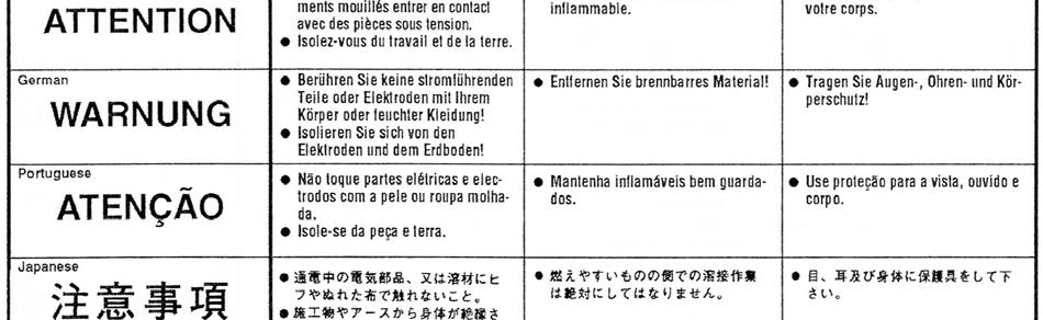
15 15 Operating machine SAFETY PRECAUTIONS WARNING! ELECTRIC SHOCK CAN KILL Do not touch electrically live parts or electrode with skin or wet clothing. Insulate yourself from work and ground Always wear dry insulating gloves WARNING! FUMES AND GASES can be dangerous Keep your head out of fumes & gases produced from welding. Use ventilation or exhaust to remove fumes & gases from breathing zone and general area. WARNING! WELDING SPARKS can cause fire or explosion Keep flammable material away from work area. Do not weld on containers that have held combustibles WARNING! ARC RAYS can burn Wear eye, ear and body protection Make sure work area is protected by proper shielding to avoid injury to passers by.
16 16 Welding in TIG mode No Pulse No remote foot pedal 1. Connect the Tig Torch to machine, connect earth lead to machine & work piece. 2. Set the TIG/MMA switch to TIG 3. Set Pulse Switch to Off position 4. Select 2 or 4 way torch operation 5. Connect Argon gas and set flow to approx 8-12 LPM 6. Set Gas post flow to 3 x diameter of tungsten width 7. Adjust Base current to desired welding current 8. Press the Tig torch switch to start welding Welding in TIG mode with Pulse No remote foot pedal 1. Connect the Tig Torch to machine, connect earth lead to machine & work piece. 2. Set the TIG/MMA switch to TIG 3. Select 2 or 4 way torch operation 4. Connect Argon gas and set flow to approx 8-12 LPM 5. Set Gas post flow to 3 x diameter of tungsten width 6. Set Pulse On/Off switch to ON 7. Adjust Pulse freq. to desired setting (how often pulse happens) 8. Adjust pulse width to desired setting (how long pulse happens) 9. Adjust base amps for minimum pulse current. 10. Adjust main current for maximum pulse current 11. Press the Tig torch switch to start welding The benefits of pulse welding is the ability to control the weld pool and amount of heat absorbed by work resulting in a smaller heat affected zone which results in fewer deformations and reduced chance of cracking. There are no set rules for pulse welding as this is down to personal choice by the welder. Welding in TIG mode with Remote foot pedal 1. Connect the Tig Torch to machine, connect earth lead to machine & work piece. 2. Connect remote foot pedal to machine 3. Set the TIG/MMA switch to TIG 4. Select 2 way torch operation Foot pedal will not work in 4-WAY mode 5. Connect Argon gas and set flow to approx 8-12 LPM 6. Set Gas post flow to 3 x diameter of tungsten width 7. Adjust Base current knob on machine to desired maximum welding current. 8. Press the foot pedal to start welding. (on maximum depression it will go to maximum amps set on machine) Note: When welding with remote foot pedal Upon pressing of foot pedal welding arc will start, if you find it hard to start arc push pedal down a bit further to aid starting. The benefits of welding with a remote foot pedal is greater control of amount of heat going into work. Press pedal fully to start weld, upon weld pool formation you can slightly release the pedal to decrease amperage to sustain perfect weld pool and increase again as required to sustain weld characteristics. The foot pedal adjusts from Start (min) current to maximum current as set on main current knob on front of machine.
17 17 Tig tungsten size / amperage guide All values below are based on using pure argon shielding gas. Other current values may be employed depending on the shielding gas and application Electrode Diameter (mm) ELECTRODE 2% Thoriated on DC (amps) Red Tip Grind to point RATINGS Pure Tungsten on DC (amps) Zirconiated 0.8% Tungsten on AC (amps) White Tip No need to grind 1.0mm / mm / 1/ mm/ 3/ mm / 1/ mm / 5/ mm / 3/ mm / 1/ Welding in STICK MMA (SMAW) Mode 1. Fit MMA electrode holder to machine 2. Fit earth lead to machine and to work piece 3. Select MMA on MMA/TIG switch 4. Place electrode in holder 5. Select desired welding base current 6. Strike arc and weld WARNING! ELECTRIC SHOCK CAN KILL When machine is switched to MMA mode, output terminals are always live, take care and do not touch electrode and earth by person at same time, otherwise electric shock will occur. The foot pedal has no affect on welding current in MMA mode and the gas flow and high frequency starting circuit is disabled.
18 18 Maintenance Routine and periodic maintenance WARNING! ELECTRIC SHOCK CAN KILL Turn the input power OFF at the mains switch & fuse box before working on this equipment. Have a qualified electrician install & service this equipment. Allow machine to sit for 5 minutes minimum to allow the power capacitors to discharge before working inside this equipment. Do not touch electrically live parts 1. Periodically remove the side/top panels of machine and clean out machine with a low pressure dry air line paying particular attention to PC Boards, Fan blades, HF points 2. Inspect input and output cables & hoses for fraying, cuts & bare spots 3. Keep tig torch and cables in good condition 4. Clean air vents to ensure proper air flow and cooling 5. The fan motor has sealed bearings which requires no maintenance Troubleshooting Service & repair should only be performed by R-Tech welding trained personnel. Unauthorised repairs performed on this welding equipment may result in danger or injury to the technician and machine operator and will invalidate your warranty. For your safety and to avoid electric shock, please observe all safety notes and precautions detailed throughout this manual The troubleshooting guide is provided to help you locate possible machine malfunctions If fault / problem is not listed below check our Tig Welder Support page on our website or contact R-Tech by phone. Contact details can be found on front of this manual and our website
19 19 Tig welding problems No output - Power light is not lit Check machine on/off switch is in the on position Check Input power to machine Check plug wiring Check mains trip / fuses No output - Fan runs - Power light is lit Check torch connections are secure and torch switch operation, try replacing tig torch. If you have a multi-meter check continuity between pins 1 and 2 on torch switch plug when pressing torch switch No output - Power light is lit - Warning light is lit Welding application may have exceeded recommended duty cycle, allow machine to cool down until the warning light goes out. No output Power light is lit Gas at torch end when trigger pressed Check torch condition possible break in torch power cable replace torch Machine keeps overheating - Warning light is lit on machine Check if fan is running if not contact R-Tech for repair Check the cooling vents for obstruction, blow out machine with clean dry low pressure air supply. Check for adequate ventilation around machine Porosity in weld No / low gas at torch tip Check gas supply from gas bottle Check flow rate on regulator Check gas hose for restrictions Check for draughts in local area, open doors etc Replace tig torch may have gas restriction Poor weld penetration Check condition of earth lead and clamp and ensure clamp is connection via a clean area on work piece Check condition of tig torch, try other tig torch
20 20 Machine stuck on minimum amps when welding although higher amperage has been set Make sure machine has not been set to 4-way operation as when in this mode when you press torch switch you get minimum amps and when you let go of switch machine will go to maximum amps set. When using foot pedal machine is stuck on minimum amps Make sure 2/4 way switch is in 2 way position, the remote foot pedal will not work in the 4- way position, this is for torch switch operation only. Arc Flutters when TIG welding 1. Tungsten electrode may be too large in diameter for the current setting. 2. Tungsten not sharp when in DC mode 3. Gas shielding flow may be low or high, check gas flow, reduce tungsten stick out beyond ceramic 4. Check for leaks in torch & gas hoses Black areas along weld bead 1. Clean any oily or organic contamination from the work piece 2 Tungsten electrode contaminated. Replace or sharpen 3 Check for leaks or contamination on gas hoses & connections. 4 Gas flow may be insufficient, Increase gas flow, reduce tungsten stick out from ceramic Weak HF Poor arc striking welding output normal 1 Check torch and earth connections is torch cable insulation in good condition. 2 Check for leaks or contamination on gas hoses & connections. 3 Gas flow may be insufficient, increase gas flow, reduce tungsten stick out from ceramic 4 Keep output cables short as possible HF spark is present at the tungsten electrode but unable to start welding arc, Machine has normal welding output 1 Tungsten may be contaminated - replace or sharpen 2 The current may be set too low 3 Tungsten may be to large for process 4 Gas flow may be insufficient, increase gas flow, reduce tungsten stick out from ceramic
21 21 No HF when torch trigger pressed, no blue spark between HF points Examine and clean HF points with clean dry low pressure air line HF PCB faulty Contact R-Tech for repair MMA Stick welding problems Stick electrode blasts off when arc is struck Welding current set to high, reduce amperage or use thicker electrode Contaminated electrodes or material Electrode sticks in weld puddle Welding current is set too low Arc is too short, keep electrode further away from work Excessive splatter Too long an arc, keep electrode closer to work Poor penetration Travel speed too fast Too much welding current, reduce welding amperage Porosity in weld Electrodes are damp Arc too long, get electrode closer to work
22 22


23 23


24 24
MMA 160S ARC/MMA WELDER OPERATION INSTRUCTIONS
 www.r-techwelding.co.uk MMA 160S ARC/MMA WELDER OPERATION INSTRUCTIONS 2 Thank you for selecting the R-Tech MMA160S Inverter Arc Welder. The MMA160S has many benefits over traditional Arc welders, including
OPERATION INSTRUCTIONS
 www.r-techwelding.co.uk email: sales@r-techwelding.co.uk Tel: 01452 733933 Fax 01452 733939 TIG160PDC DC TIG WELDER OPERATION INSTRUCTIONS Version 2014-1 2 Thank you for selecting the R-Tech Tig160PDC
OPERATION INSTRUCTIONS
 www.r-techwelding.co.uk Email: sales@r-techwelding.co.uk Tel: 01452 733933 Fax: 01452 733939 ProArc 175 INVERTER ARC WELDER OPERATION INSTRUCTIONS Version 2017-10 2 3 Thank you for selecting the R-Tech
OPERATION INSTRUCTIONS
 www.r-techwelding.co.uk Tel: 01452 733933 Fax 01452 733939 PLASMA 50HF INVERTER PLASMA CUTTER OPERATION INSTRUCTIONS Version 2014-1 2 Thank you for selecting the R-Tech PLASMA 50HF Inverter Plasma Cutter
OPERATION INSTRUCTIONS
 PLASMA 30DV DUAL VOLTAGE INVERTER PLASMA CUTTER OPERATION INSTRUCTIONS 2 Thank you for selecting the R-Tech Plasma 30DV Inverter Plasma Cutter 3 The Plasma 30DV has many benefits over traditional transformer
OPERATING INSTRUCTIONS
 www.r-techwelding.co.uk email: sales@r-techwelding.co.uk Tel: 01452 733933 Fax 01452 733939 IMIG 180 PORTABLE INVERTER MIG/MAG/MMA WELDER OPERATING INSTRUCTIONS Version 2017-1 Thank you for selecting
POWER MTS210D MIG - TIG - MMA WELDING MACHINE OPERATION INSTRUCTIONS
 www.r-techwelding.co.uk email: sales@r-techwelding.co.uk Tel: 01452 733933 Fax 01452 733939 POWER MTS210D MIG - TIG - MMA WELDING MACHINE OPERATION INSTRUCTIONS Version 2014-1 2 Thank you for selecting
Tel: Fax MTS255S
 www.r-techwelding.co.uk email: sales@r-techwelding.co.uk Tel: 01452 733933 Fax 01452 733939 MTS255S MIG-TIG-MMA WELDING MACHINE OPERATION INSTRUCTIONS Version 2017-10 - 2 - Thank you for selecting the
WELDING INVERTER. PEGAS 160 E Smart PEGAS 200 E Smart OPERATING MANUAL. ALFA IN a.s. PEGAS E Smart Manual EN 04
 WELDING INVERTER PEGAS 160 E Smart PEGAS 200 E Smart OPERATING MANUAL PEGAS 160-200 E Smart Manual EN 04 2/12 CONTENT: 1. INTRODUCTION... 3 2. SAFETY INSTRUCTIONS AND WARNINGS... 4 3. TECHNICAL DATA...
Caddy. Tig 2200i AC/DC. Instruction manual GB Valid for: serial no. 711-, 747-xxx-xxxx
 Caddy Tig 2200i AC/DC Instruction manual 0460 225 301 GB 20180920 Valid for: serial no. 711-, 747-xxx-xxxx TABLE OF CONTENTS 1 SAFETY... 4 1.1 Meaning of symbols... 4 1.2 Safety precautions... 4 2 INTRODUCTION...
INVERTER AIR PLASMA CUTTING MACHINE
 INVERTER AIR PLASMA CUTTING MACHINE OPERATION MANUAL DO NOT INSTALL, OPERATE OR MAINTAIN THIS MACHINE WITHOUT READING THIS MANUAL AND PLEASE ALWAYS THINK BEFORE YOU ACT. www.hyundaiwelding.com TECHNICAL
Table of Contents Foreword I. Product Introduction II. Notice For Safety III. Main Technical Parameters IV.
 Foreword Thank you for choosing the LGK-ID IGBT Digital Air Plasma Cutter of Delixi (Hangzhou) Inverter Co., Ltd. Before use LGK-ID IGBT Digital Air Plasma Cutter, please carefully read this Manual to
MMWTIG241I OWNER S MANUAL
 MMWTIG241I OWNER S MANUAL WARNING: Read carefully and understand all ASSEMBLY AND OPERATION INSTRUCTIONS before operating. Failure to follow the safety rules and other basic safety precautions may result
DIGI-CUT 40PFC MV. Part No. 9030H OPERATOR S MANUAL
 DIGI-CUT 40PFC MV Part No. 9030H OPERATOR S MANUAL IMPORTANT Read this Owner s Manual completely before attempting to use this equipment. Save this manual and keep it handy for quick reference. Pay particular
SIP Direct Drive Oil-Lube Air Compressors - Operating & Maintenance Instructions
 SIP Direct Drive Oil-Lube Air Compressors - Operating & Maintenance Instructions Please read and fully understand the instructions in this manual before operation. Keep this manual safe for future reference.
Cutlass Fasteners, Inc. 83 Vermont Ave., Unit 6, Warwick, RI Tel: (401) Fax: (401) cutlass-studwelding.com
 Fax: (401) cutlass-studwelding.com") MODEL : BANTAM C8 PART NO. : 602-325P SERIAL NO. : PLEASE READ THIS OPERATION AND MAINTENANCE MANUAL CAREFULLY BEFORE USING YOUR NEW CUTLASS STUD WELDER. COPYRIGHT CFI 2009 email: sales@ PAGE - 1 - WARRANTY
MODEL : BANTAM C8 PART NO. : 602-325P SERIAL NO. : PLEASE READ THIS OPERATION AND MAINTENANCE MANUAL CAREFULLY BEFORE USING YOUR NEW CUTLASS STUD WELDER. COPYRIGHT CFI 2009 email: sales@ PAGE - 1 - WARRANTY
QUATRO 450 OPERATOR S MANUAL
 QUATRO 450 OPERATOR S MANUAL IMPORTANT DO NOT INSTALL, OPERATE OR REPAIR THIS EQUIPMENT WITHOUT READING THIS MANUAL AND THE SAFETY SECTION CONTAINED INSIDE THIS MANUAL STARWELD WELDING SOLUTIONS WEBSITE:
SPEEDTEC 200C BR OPERATOR S MANUAL IM /2016 REV03 ENGLISH
 SPEEDTEC 200C BR OPERATOR S MANUAL IM3058 05/2016 REV03 ENGLISH Lincoln Electric Bester Sp. z o.o. ul. Jana III Sobieskiego 19A, 58-263 Bielawa, Poland www.lincolnelectric.eu 12/05 THANKS! For having chosen
MULTIVOLTAGE PORTABLE BATTERY CHARGER MVM
 _ M MULTIVOLTAGE PORTABLE BATTERY CHARGER MVM User's MANUAL Code: MVM Version: 01-BF Date: OCT 2005 Page 1/10 _ 1. INTRODUCTION Before starting to use your Energic plus MVM battery charger, please take
INSTRUCTION MANUAL FOR PLASMA CUTTER
 INSTRUCTION MANUAL FOR PLASMA CUTTER IMPORTANT: BEFORE STARTING THE EQUIP- MENT, READ THE CONTENTS OF THIS MANUAL, WHICH MUST BE STORED IN A PLACE FAMILIAR TO ALL USERS FOR THE ENTIRE OPERATIVE LIFE-SPAN
BATTERY CHARGER-STARTER
 BATTERY CHARGER-STARTER MODEL NO: WBC240 & WBC400 PART NO: 6261505 & 6261515 OPERATION & MAINTENANCE INSTRUCTIONS GC0116 INTRODUCTION Thank you for purchasing this CLARKE Battery Charger/Starter. Please
Cutlass Fasteners, Inc. 83 Vermont Ave., Unit 6, Warwick, RI Tel: (401) Fax: (401) cutlass-studwelding.com
 Fax: (401) cutlass-studwelding.com") MODEL : BANTAM C8 BANTAM C10 PART NO. : 602-325A 602-343A SERIAL NO. : PLEASE READ THIS OPERATION AND MAINTENANCE MANUAL CAREFULLY BEFORE USING YOUR NEW CUTLASS STUD WELDER. COPYRIGHT CFI 2009 email: sales@
MODEL : BANTAM C8 BANTAM C10 PART NO. : 602-325A 602-343A SERIAL NO. : PLEASE READ THIS OPERATION AND MAINTENANCE MANUAL CAREFULLY BEFORE USING YOUR NEW CUTLASS STUD WELDER. COPYRIGHT CFI 2009 email: sales@
ARC 1850 LIST OF FIGURES
 PAGE 1.0 INTRODUCTION... 1 2.0 WARRANTY... 1 3.0 UNPACKING YOUR UNIT... 1 4.0 SUGGESTED SAFETY PRECAUTIONS...... 1 4.1 PERSONAL SAFETY PRECAUTIONS. 1 4.2 POWER SUPPLY SAFETY PRECAUTIONS.. 2 5.0 GENERAL
1200W INVERTER GENERATOR
 1200W INVERTER GENERATOR MODEL NO: IG1200 PART NO: 8877070 OPERATION & MAINTENANCE INSTRUCTIONS LS0117 INTRODUCTION Thank you for purchasing this CLARKE 1200W Inverter Generator. Before attempting to use
OWNER S MANUAL. Affordable Tools Achieve More. LT3500. Visit Our Website at:
 Affordable Tools Achieve More Visit Our Website at: www.uwelding.com @lotostech LT3500 OWNER S MANUAL Carefully read the operation manual prior to using, Installing and maintaining the electric welding
JM-160C,JM-175C, JM-180C, JM-200C
 wilkinsonstar.com MIG Series MIG/MAG/MMA Compact welding machines Order code! JM-160C,JM-175C, JM-180C, JM-200C OPERATOR MANUAL Your new product Thank you for selecting this Jasic Technology, Wilkinson
OPERATION MANUAL M185. MIG/flux wire feeder welder. Serial Number: Where Purchase: Date of purchased:
 OPERATION MANUAL M185 MIG/flux wire feeder welder Serial Number: Where Purchase: Date of purchased: CONTENT 1. Safety... 2 2. Electrical principle drawing... 4 3. Specifications... 5 4. Front and rear
DISCHARGER-ANALYZER BDX USER'S MANUAL
 BATTERY DISCHARGER-ANALYZER BDX USER'S MANUAL OWM-BDX-261006 Page 1/10 1. INTRODUCTION Before starting to use your BDX battery discharger/analyzer, please take the time to read these instructions carefully.
User s Manual. Automatic Switch-Mode Battery Charger
 User s Manual Automatic Switch-Mode Battery Charger IMPORTANT Read, understand, and follow these safety rules and operating instructions before using this battery charger. Only authorized and trained service
Inverter User Manual
 Inverter User Manual -------------for standard model DC TO AC Power Inverter CONTENTS Safety First 1. Introduction 2. Installation Guidelines 3. Using the inverter 4. Troubleshooting 5. Specifications
Model: OBD-L On-Board-Diagnostics II Memory Saver Detector
 Model: OBD-L On-Board-Diagnostics II Memory Saver Detector OWNERS MANUAL IMPORTANT SAFETY INSTRUCTIONS SAVE THESE INSTRUCTIONS This manual will show you how to use your memory saver detector safely and
SPEEDTEC 215C OPERATOR S MANUAL IM /2016 REV01 ENGLISH
 SPEEDTEC 215C IM3057 06/2016 REV01 OPERATOR S MANUAL ENGLISH Lincoln Electric Bester Sp. z o.o. ul. Jana III Sobieskiego 19A, 58-263 Bielawa, Poland www.lincolnelectric.eu Declaration of conformity Lincoln
Go Power! Manual. GP-1750HD Inverter GP-2500 Inverter
 Go Power! Manual GP-1750HD Inverter GP-2500 Inverter Go Power! Electric Inc. PO Box 6033 Victoria, BC V8P 5L4 Tel: 866-247-6527 Fax: 866-607-6527 Email: info@gpelectric.com Table of Contents 1. INTRODUCTION...
GSL Electronics Modified Sine Wave Power Inverters
 GSL Electronics Modified Sine Wave Power Inverters Congratulations on choosing one of our Modified Sine Wave Inverters for your application. There are 6 models in the range, which will meet most of your
OPERATION MANUAL MODELS TWE-250 TWE-321 TWE-375 TRU WELD EQUIPMENT COMPANY 6400 N. HONEYTOWN ROAD SMITHVILLE, OHIO (330)
") OPERATION MANUAL MODELS TWE-250 TWE-321 TWE-375 TRU WELD EQUIPMENT COMPANY 6400 N. HONEYTOWN ROAD SMITHVILLE, OHIO 44677 (330) 669 2773 CONTENTS Section Description Pages 1 Introduction 3 2 External Features
OPERATION MANUAL MODELS TWE-250 TWE-321 TWE-375 TRU WELD EQUIPMENT COMPANY 6400 N. HONEYTOWN ROAD SMITHVILLE, OHIO 44677 (330) 669 2773 CONTENTS Section Description Pages 1 Introduction 3 2 External Features
POWER PINNER CD HAND WELDER 7300 OPERATOR S MANUAL
 POWER PINNER CD HAND WELDER 7300 OPERATOR S MANUAL Copyright: April 7, 2014 Gripnail Corporation Revised: January 25, 2018 An Employee Owned Company 97 Dexter Road East Providence, Rhode Island 02914-2045
Pro Booster 802Li. Please read and fully understand the instructions in this manual before operation. Keep this manual safe for future reference.
 Please dispose of packaging for the product in a responsible manner. It is suitable for recycling. Help to protect the environment, take the packaging to the local amenity tip and place into the appropriate
OWNER S MANUAL. Affordable Tools Achieve More. MIG140. Visit Our Website at:
 Affordable Tools Achieve More Visit Our Website at: www.uwelding.com MIG140 OWNER S MANUAL Carefully read the operation manual prior to using, installing and maintaining the electric welding machine IMPORTANT
Chargestar P24 / P32 Battery Charger Startmaster P300 Starter / Charger
 Please dispose of packaging for the product in a responsible manner. It is suitable for recycling. Help to protect the environment, take the packaging to the local amenity tip and place into the appropriate
MODEL 2602A-12 3 STAGE AUTOMATIC BATTERY CHARGER OWNER S MANUAL SAVE THESE INSTRUCTIONS
 R A Valley Forge Company MODEL 2602A-12 3 STAGE AUTOMATIC BATTERY CHARGER OWNER S MANUAL SAVE THESE INSTRUCTIONS 1. INTRODUCING THE CHARGER The 2602A-12 is a 3-stage electronic battery charger. Rainproof,
AIR COMPRESSOR OPERATING INSTRUCTION AND PARTS LIST
 AIR COMPRESSOR OPERATING INSTRUCTION AND PARTS LIST BELT TYPE IMPORTANT PLEASE MAKE CERTAIN THAT THE PERSON WHO IS TO USE THIS EQUIPMENT CAREFULLY READS AND UNDERSTANDS THESE INSTRUCTIONS BEFORE STARTING
SUBMERSIBLE PUMP HSE RANGE
 SUBMERSIBLE PUMP HSE RANGE OPERATION & MAINTENANCE INSTRUCTIONS 0707 SPECIFICATIONS HSE300* HSE360* Model No. HSE130* HSE200A HSE300A HSE360A HSEC400* HSE301A HSE361A Outlet Dia. (mm/inches) 32/1-1/4 38/1-1/2
ATD WATT INVERTER
 ATD-5954 1500 WATT INVERTER Welcome. This ATD product has been carefully engineered and manufactured to give you dependable operation. Please read this manual thoroughly before operating your new ATD product,
Pure Sine Wave Inverter GP-HS1500. Owner s Manual
 Pure Sine Wave Inverter GP-HS1500 Owner s Manual 2 Table of Contents Introduction 3 Specifications 4 Name and Main Function 5 Installation 7 Operation 9 Operating Limits 13 Troubleshooting 13 Maintenance
OWNER S OPERATING MANUAL
 OWNER S OPERATING MANUAL ARC 140 AMP WELDER TABLE OF CONTENTS Page Safety instructions 3-4 Inverter Arc Welder 5 Welder Information 5 Arc 140 AMP welder set up 6 Assembly instructions 6 Operation 7 Welding
10 AMP ON BOARD BATTERY CHARGER
 R A Valley Forge Company MODEL 2611A-1-B 10 AMP ON BOARD BATTERY CHARGER One Output OWNER S MANUAL IMPORTANT! READ THESE INSTRUCTIONS BEFORE INSTALLING AND USING THIS PRODUCT. Keep these instructions for
Cruising Charger Series OWNER S MANUAL
 R Cruising Charger Series OWNER S MANUAL ON BOARD BATTERY CHARGERS Models DC Amperage No. Of Banks Volts 2614A 5,10 Amps 2 Bank 12/12 2614A-230 2621A 5,5,10 Amps 3 Banks 12/12/12 2621A-230 2622A 10,10
WELDING POSITIONER OPERATION MANUAL MODEL TT-100 V1.0
 WELDING POSITIONER OPERATION MANUAL MODEL TT-100 Carefully read and understand these operation instructions before operating, inspecting, or servicing this product. This manual for use with Serial Numbers
OWNER S OPERATING MANUAL
 OWNER S OPERATING MANUAL WELD AND CUT ARC/TIG INVERTER PLASMA 30 PLASMA CUTTER TABLE OF CONTENTS Safety instructions 3-4 Weld & Cut ARC/TIG and Plasma Cutter 5 Page Installation 6 Welder Information 6-8
5 IN 1 JUMP START OPERATION & MAINTENANCE INSTRUCTIONS MODEL NO: JS5IN1 PART NO: LS0810
 5 IN 1 JUMP START MODEL NO: JS5IN1 PART NO: 6240005 OPERATION & MAINTENANCE INSTRUCTIONS LS0810 INTRODUCTION Thank you for purchasing this CLARKE product. Before attempting to use this product, please
POWER TROLLEY 8 INSTRUCTION MANUAL POWER TROLLEY 8. Model: SINE Instruction Manual for: Self-Contained Sinewave Mobile Power Backup System
 POWER TROLLEY 8 Model: SINE 1548 Instruction Manual for: Self-Contained Sinewave Mobile Power Backup System Version 07 CONTENTS Page 1. INTRODUCTION... 1 2. USING THE POWER TROLLEY.... 2 3. BATTERY BACKUP
Stick/Mig Capability Welding Excellence Modular Construction Environment Protected 2,000 Watt AC Power for Tools
 E300 3+2 Electric Welder Service Manual Stick/Mig Capability Welding Excellence Modular Construction Environment Protected 2,000 Watt AC Power for Tools SVM_E300 3+2 SAFETY Arc Welding Safety Precautions
230V DIESEL FUEL TRANSFER PUMP MODEL NO: DFT230
 230V DIESEL FUEL TRANSFER PUMP MODEL NO: DFT230 PART NO: 7160050 OPERATION & MAINTENANCE INSTRUCTIONS GC0816 INTRODUCTION Thank you for purchasing this CLARKE Pump. The DFTP230 pump is a self-priming rotary
LEAD ACID BATTERY CHARGER
 LEAD ACID BATTERY CHARGER MODEL NO: LA4 & LA6 OPERATION & MAINTENANCE INSTRUCTIONS LS1214 INTRODUCTION Thank you for purchasing this CLARKE Battery Charger. Please read this manual thoroughly, before attempting
BATTERY BOOSTER/CHARGER MODEL NO: DIGICAR 600
 BATTERY BOOSTER/CHARGER MODEL NO: DIGICAR 600 PART NO: 6261200 OPERATION & MAINTENANCE INSTRUCTIONS LS0815 INTRODUCTION Thank you for purchasing this CLARKE Battery booster / charger which is suitable
LDG6000SA DIESEL GENERATOR OWNERS MANUAL
 LDG6000SA DIESEL GENERATOR OWNERS MANUAL BEFORE OPERATING THIS EQUIPMENT PLEASE READ THESE INSTRUCTIONS CAREFULLY Preface Thank-you for purchasing this generator. This operation manual contains information
PI1500X Power Inverter User s Manual
 PI1500X Power Inverter User s Manual featuring WARNING Failure to follow instructions may cause damage or explosion, always shield eyes. Read entire instruction manual before use. Warning: This product
VERSA-CUT 60 PLASMA CUTTER
 Part #14099 VERSA-CUT 60 PLASMA CUTTER ASSEMBLY & OPERATING INstructions (PDF version available at eastwood.com/14099manual) Our Eastwood-designed Versa-Cut 60 Plasma Cutter is your smartest choice for
PS MIG Volt MIG Welder Assembly & Operating Instructions
 PS07570 201205 MIG135 115 Volt MIG Welder Assembly & Operating Instructions READ ALL INSTRUCTIONS AND WARNINGS BEFORE USING THIS PRODUCT. This manual provides important information on proper operation
SUBMERSIBLE PUMP HSE RANGE
 SUBMERSIBLE PUMP HSE RANGE OPERATION & MAINTENANCE INSTRUCTIONS 0806 SPECIFICATIONS Model No. HSE120* HSE200 HSE300*/ HSE360*/ HSEC400* HSE301 HSE361 Outlet Dia. (mm/inches) 32/1-1/4 38/1-1/2 50/2 50/2
3000W POWER INVERTER. User Manual
 3000W POWER INVERTER User Manual Posts AC outlets Digital display ON/OFF button Remote control connection port (remote control switch is not included) USB port Two set of heavy duty input cable P a g e
For use with machine Code POWERPLUS II 350 K POWERPLUS II 500 K
 IM7003-5 Otc, 2009 Rev. 1 POWERPLUS Ⅱ 350/500 For use with machine Code POWERPLUS II 350 K32063-1 POWERPLUS II 500 K32064-1 Safety Depends on You Lincoln arc welding and cutting equipment is designed and
6 Litre Oil-Less Air Compressor
 Operator s Manual 6 Litre Oil-Less Air Compressor WARNING! Before using this appliance, read the Operator s manual and follow all its safety rules and instructions. SPECIFICATION HWKAC1 1.1 kw / 1.5 HP
DC TO AC POWER INVERTER
 DC TO AC POWER INVERTER 12V / 24V / 48Vdc Input 115V / 230Vac Output 150W ~ 6000W Output cont. L-Series User Manual Before install and use your Inverter, read the User Manual and safety instructions. Cooler
HIGH FREQUENCY AUTOMATIC BATTERY CHARGER
 HIGH FREQUENCY AUTOMATIC BATTERY CHARGER MODEL NO: HFBC12 PART NO: 6267000 OPERATION & MAINTENANCE INSTRUCTIONS LS0814 INTRODUCTION Thank you for purchasing this CLARKE High Frequency Automatic Battery
OPERATOR S MANUAL STUDPRO SERIES
 OPERATOR S MANUAL STUDPRO SERIES Capacitor Discharge Stud Welder MODELS: StudPro 2500XI StudPro 2500XIP StudPro 3125XI StudPro 3750XI CONTENTS Description Pages Safety 2 Specifications and Features 3 Product
OPERATION/ MAINTENANCE MANUAL
 208 VERSION OPERATION/ MAINTENANCE MANUAL TABLE OF CONTENTS Section 1 SAFETY PRECAUTIONS PAGE 1.0 INTRODUCTION... 1 2.0 WARRANTY... 1 3.0 UNPACKING YOUR UNIT... 1 4.0 SUGGESTED SAFETY PRECAUTIONS... 1
LOTOS MIG175 MIG Welder
 LOTOS MIG175 MIG Welder TABLE OF CONTENTS SAFETY...... 3 SPECIFICATIONS... 8 General Description...8 What s Included.....8 Power Supply Ratings.....9 Machine Rear..10 Front Control Panel.10 Side Components...11
DC AC POWER INVERTER. LIV 10 / LIV 20 / LIV 30 User Manual
 DC AC POWER INVERTER LIV 10 / LIV 20 / LIV 30 User Manual Save This Manual Please read this manual carefully prior to storage, installation, wiring, operation and maintenance of the Power Inverter. This
CDMF110 PINSPOTTER OWNER S MANUAL MACHINERY DIVISION
 CDMF110 c d m f 1 1 CDMF110 PINSPOTTER OWNER S MANUAL MACHINERY DIVISION UNIT INSTRUCTIONS Please follow all CDMF110 Safety Instructions. Contact your Duro Dyne Tech Service if you have any operating questions.
Cordless Rechargeable Saw Instructions for Use
 Technical data Voltage: DC 10.8V Weight: 1.25Kg Stroke rate: 0-2100/min Stroke: 15mm Cutting capacity: max diameter in wood 80mm / in soft metal 7mm Charging time: Between 5.0-5.5 Hours Battery: 1.3Ah
MTS 200 User Manual TSX1D200MTS SWMTS001
 MTS 200 User Manual SWMTS001 DECLARATION OF CONFORMITY The Low voltage Directive 2006/95/EC of 12 December 2006, entering into force 16 January 2007 Type of Equipment Welding power source for MIG/MAG,
ATD WATT INVERTER
 ATD-5955 2000 WATT INVERTER Welcome. This ATD product has been carefully engineered and manufactured to give you dependable operation. Please read this manual thoroughly before operating your new ATD product,
OPERATOR S MANUAL StudPro LiteXI Pin Welder Stud Welding Products, Inc
 OPERATOR S MANUAL StudPro LiteXI Pin Welder CONTENTS Description Pages Safety 2 Specifications and Features 3 Product Components 4-5 Screen Operation 6-8 Setup and Welding 9-11 CD Gun Exploded View 12
CFT24 &CFT230 PART NOS:
 FUEL TRANSFER PUMP Model Nos. CFT12, CFT24 &CFT230 PART NOS: 7160010, 7160020 & 7160030 INSTALLATION & OPERATING INSTRUCTIONS ORIGINAL INSTRUCTIONS GC05/18 REV 5 INTRODUCTION Thank you for purchasing this
Users Manual. Defender 1 8.0KW to 14.0KW Online Emergency Lighting Inverter. Technical Manual # Revision B
 Users Manual Defender 1 8.0KW to 14.0KW Online Lighting Inverter Technical Manual #018-0102-01 Revision B Phone: 1.877.DSPM.POWER 1.877.377.6769 Fax: 909.930.3335 Website: www.dspmanufacturing.com E-Mail:
OPERATION MANUAL MODELS TWE-250 TWE-321 TWE-375 TRU WELD EQUIPMENT COMPANY 6400 N. HONEYTOWN ROAD SMITHVILLE, OHIO (330)
") OPERATION MANUAL MODELS TWE-250 TWE-321 TWE-375 TRU WELD EQUIPMENT COMPANY 6400 N. HONEYTOWN ROAD SMITHVILLE, OHIO 44677 (330) 669 2773 Version 1.3 Date 10/20/2010 TRU WELD EQUIPMENT LIMITED WARRANTY All
OPERATION MANUAL MODELS TWE-250 TWE-321 TWE-375 TRU WELD EQUIPMENT COMPANY 6400 N. HONEYTOWN ROAD SMITHVILLE, OHIO 44677 (330) 669 2773 Version 1.3 Date 10/20/2010 TRU WELD EQUIPMENT LIMITED WARRANTY All
BATTERY BOOSTER/CHARGER MODEL NO: DIGICAR 900
 BATTERY BOOSTER/CHARGER MODEL NO: DIGICAR 900 PART NO: 6261205 OPERATION & MAINTENANCE INSTRUCTIONS LS0715 INTRODUCTION Thank you for purchasing this CLARKE Battery booster / charger which is suitable
NSGV PT-1000 PORTABLE WELDING STATION I, O & M MANUAL
 APPLICATION OF DUST CONTROL EQUIPMENT: CAUTION - Warning Improper operation of dust control system may contribute to conditions in the work area or facility that could result in severe personal injury
Users Manual. Cobra Plus Stand-By Emergency Lighting Inverter. Technical Manual # Revision B
 Users Manual Cobra Plus Stand-By Lighting Inverter Technical Manual #018-0110-01 Revision B Phone: 1.877.DSPM.POWER 1.877.377.6769 Fax: 909.930.3335 Website: www.dspmanufacturing.com E-Mail: techsupport@dspmanufacturing.com
MODEL 6010A 6 12 VOLT BATTERY CHARGER ASSOCIATE
 MODEL 600A 6 VOLT BATTERY CHARGER ASSOCIATE IMPORTANT SAFETY INSTRUCTIONS. SAVE THESE INSTRUCTIONS. This manual contains important safety and operating instructions for the battery charger you have purchased.
Model: SE-4020-CA Automatic Battery Charger
 OWNERS MANUAL Model: SE-4020-CA Automatic Battery Charger PLEASE SAVE THIS OWNERS MANUAL AND READ BEFORE EACH USE. This manual will explain how to use the battery charger safely and effectively. Please
1. INTRODUCTION SYSTEM DESCRIPTION Front Panel CONNECTION AND OPERATION TROUBLESHOOTING...8
 Contents : 1. INTRODUCTION...1 2. IMPORTANT SAFETY INSTRUCTIONS...2 3. SYSTEM DESCRIPTION...4 3.1 Front Panel...4 4. CONNECTION AND OPERATION...6 5. TROUBLESHOOTING...8 6. MAINTENANCE...9 6.1 Operation...9
Owner s Guide. DC TO AC Power Inverter
 Owner s Guide DC TO AC Power Inverter CONTENTS Safety First 1 1. Introduction 7 2. Installation Guidelines 9 3. Using the inverter 15 4. Troubleshooting 27 5. Specifications 33 Type CP SP Efficiency THD
1000 Watt Power Inverter INSTRUCTION MANUAL HT87112-AUOXY
 1000 Watt Power Inverter INSTRUCTION MANUAL HT87112-AUOXY CONTENTS Warranty 2 Introduction 3 Environmental protection 3 Specifications 3 General safety warnings and instructions 4 Important safety instructions
Matala. VersiFlow Series. Instruction and Maintenance Manual
 VersiFlow Series High Flow Multi-Purpose "Versatile " Pump V-3200 1/5HP 150W / Discharge 2 V-3900 1/3HP 250W / Discharge 2 V-4700 1/2HP 400W / Discharge 2 V-5600 1HP 750W / Discharge 2 Instruction and
Power InverterTM Watt. Continuous. User's Manual. WAGAN Corp. Limited Warranty Registration Form. Item no
 WAGAN Corp. Limited Warranty Registration Form All WAGAN Corporation products are warranted to the original purchaser of this product. Warranty Duration: This product is warranted to the original purchaser
Art. No. EC-315. Art. No. EC-330. Art. No. EC-340 SWITCH-MODE BATTTERY CHARGER CONTENTS IMPORTANT SAFETY PRECAUTIONS... 2
 SWITCH-MODE BATTTERY CHARGER CONTENTS IMPORTANT SAFETY PRECAUTIONS... 2 DESCRIPTION AND FEATURES... 3 CHARGING STAGES... 4 Art. No. EC-315 Art. No. EC-330 Art. No. EC-340 PROTECTIONS... 5 INSTALLATION...
INSTRUCTION MANUAL ANGLE GRINDER PT W
 INSTRUCTION MANUAL ANGLE GRINDER PT50360 4½ INCHES 120V 60Hz 600W 5A 12,000 rpm C US Note : Before operating this tool, read this manual and follow all safety rules and operating instructions. This electric
WARNINGS, CAUTIONS AND NOTES
 Welcome Please read this manual thoroughly before installing and operating your new Power Bright Power Inverter. This manual contains information you need to obtain the performance required for your application.
Service Bulletin Trucks
 Volvo Trucks North America, Inc. Greensboro, NC USA Service Bulletin Trucks Date Group No. Page 9.2003 300 004 1(10) General Safety Practices Electrical and Electronics VN, VHD General Safety Practices
GP-1000 Inverter. Go Power! Electric Inc. PO Box 6033 Victoria, BC V8P 5L4 Tel: Fax:
 Go Power! Manual GP-1000 Inverter Go Power! Electric Inc. PO Box 6033 Victoria, BC V8P 5L4 Tel: 866-247-6527 Fax: 866-607-6527 Email: info@gpelectric.com Table of Contents 1. INTRODUCTION 3 2. SPECIFICATIONS
MP V 8A Electronic Smart Charger. Instruction and Information Manual
 MP7428 12V 8A Electronic Smart Charger Instruction and Information Manual In order to ensure correct and safe usage of your battery charger, you should read these instructions carefully. Please retain
VT Oil-Free Range Operators Handbook
 VT Oil-Free Range Operators Handbook Covering Models:- VT7 / VT7D VT10 / VT10D VT200 / VT200D VT300 / VT300D VT00 / VT00D BAMBI AIR COMPRESSORS LTD 12 Thimble Mill Lane Heartlands Birmingham B7 HT Tel:
SOS SERIES SOS1 SOS2. Spares On Site Battery Cabinet Installation Guide rEV3
 Atlantic Battery Systems 1065 Market Street Paterson, NJ 07513 Phone: (800) 875-0073 Fax: (973) 523-2344 sales@atbatsys.com www.atbatsys.com SOS1 SOS2 SOS SERIES Spares On Site Battery Cabinet Installation
1000-Watt Energy Center
 1000-Watt Energy Center OPERATING INSTRUCTIONS Patent Pending Sierra Wave 1000-Watt Energy Center #9675 The Sierra Wave 1000-Watt Energy Center is a heavy duty and efficient portable power center offering
AMSOND INSTRUCTION MANUAL. Digital Inverter Air Plasma Cutter. MODELS: CUT 50/70 DY Series. Serial No.: Automatic Dual Voltage 110 / 220V
 INSTRUCTION MANUAL Digital Inverter Air Plasma Cutter MODELS: CUT 50/70 DY Series Serial No.: AMSOND Automatic Dual Voltage 110 / 220V Copyright Ramsond Corporation. All rights protected. Unauthorized
User Manual Rittal PMC UPS 6kVA
 User Manual Rittal PMC UPS 6kVA Germany Rittal GmbH & Co. KG Auf dem Stützelberg D-35745 Herborn Tel.: ++49-27 72-5 05-0 Fax: ++49-27 72-5 05-23 19 Internet: www.rittal.de 26 Contents 1. Introduction...
Contents. Overview. Safety Instructions. Before Installation. Installation. Operation. Maintenance. Replacement Parts. System Specifications 8 01
 PrintPRO Universal Contents Overview 1 01 02 03 Overview of your extraction system (front) Overview of your extraction system (back) Overview of the Control Panel Safety Instructions 2 01 Important safety
R5000/4000 CV INSTRUCTION MANUAL. Important Information. Description. Processes. Constant Voltage Power Source
 R5000/4000 CV Description Constant Voltage Power Source Processes Important Information All persons authorised to use, repair or service the R4000/R5000 Inverter welding unit, should read the section on