Tel: Fax MTS255S
|
|
|
- Justina Kennedy
- 5 years ago
- Views:
Transcription


1 Tel: Fax MTS255S MIG-TIG-MMA WELDING MACHINE OPERATION INSTRUCTIONS Version
2 - 2 -
3 Thank you for selecting the R-Tech MTS255S Inverter Mig (Synergic) - MMA - TIG Welder. The MTS255S has many benefits over traditional transformer welders including infinite power control, adjustable arc force and features a heavy duty wire feed mechanism to provide very smooth wire feed and weld characteristics Ideal for automotive work with its minimum current of Amps and industrial welding with its maximum output of 250 Amps (MIG/TIG) and 200 amps (MMA) We want you to take pride in operating our MTS255S as much pride as we have taken in making this product for you. Please read all information in this manual before operation PLEASE EXAMINE CARTON AND EQUIPMENT FOR DAMAGE IMMEDIATELY Please record your equipment identification below for future reference. This information can be found on the data plate at rear of machine. Product: MTS255S Serial No.. Date of Purchase Where Purchased Whenever you request replacement parts or information on this equipment please always supply the information you have recorded above This product is covered by 3 years parts and labour warranty, we will cover cost of collection, repair and returning item to you within mainland UK (other areas are RTB warranty). External items, torch, earth lead etc are covered by 3 months warranty. Any faults/damage found caused by customer will be charged prorata. Please read this operator manual completely before attempting to use this equipment. Pay particular attention to the safety instructions we have provided you for your protection The level of seriousness to be applied to each section is explained below WARNING This statement appears where the information must be followed exactly to avoid serious personal injury. CAUTION This statement appears where the information must be following to avoid a minor personal injury or damage to this equipment
4 Product Description Premium features include:- Inverter power source more efficient to operate, provides smoother weld characteristics. Heavy duty wire feed unit for long working life and consistent wire feeding. MIG (Synergic) - MMA - DC Tig welding modes Infinite welding voltage to allow fine tuning of weld characteristics Adjustable arc force controls splatter ideal for thin materials Synergic Mig Operation with settings for steel, stainless steel and aluminium Mig Operation with from 25 amps to 250 amps - ideal for very thin and thick materials Digital amp & volts meters 9 memory job stores - Easily switch between stored settings for job in hand Euro type torch fittings for easy torch fitment/replacement 35% Duty cycle at maximum 40ºC Recommended Processes The R-Tech is recommended for the MIG welding processes within its output capacity of 250 Amps DC Equipment Limitations The R-Tech POWER MTS255S is protected from overloads beyond the output ratings and duty cycle as per machine specifications with thermostat protection of the output coils and rectifiers. Welding Capability Duty Cycle The R-Tech MTS255S is rated at 250 Amps(MIG) at 35% duty cycle on a ten minute basis. If the duty cycle is exceeded a thermal protector will shut machine off until the machine cools. The R-Tech MTS255S is rated at 200Amps(MMA) at 35% duty cycle on a ten minute basis. If the duty cycle is exceeded a thermal protector will shut machine off until the machine cools. The R-Tech MTS255S is rated at 250 Amps(TIG) at 35% duty cycle on a ten minute basis. If the duty cycle is exceeded a thermal protector will shut machine off until the machine cools
5 Technical Specifications Model No. Installation R-Tech POWER MTS255S Input Operation Insulation Rated Input Current Rated Output Current Duty Cycle 40 O C Duty Cycle 40 O C Output current Range 240V 1 ~ AC 50/60Hz 32AMPS 250 AMPS 250A (MIG/TIG),200A(MMA) 160A (MIG/TIG),130A(MMA) MIG: AMPS MMA: AMPS TIG: AMPS No Load Voltage 60~80V MIG Voltage Adjustment Range 14V - 29V± 3V Suitable Wire Diameter 0.6mm 0.8mm 1.0mm Class F Read entire section before starting installation WARNING! Electric Shock can kill Only qualified personnel should perform this installation. Turn off input power at the fuse box before working on this equipment. Do not touch electrically live parts. Always connect the machine to an earthed mains supply as per national recommended standards. Select suitable location Place the welder where clean cooling air can freely circulate in and out of the front & rear louvre vents. Dirt, dust or any foreign material that can be drawn through vents into welder must be kept to a minimum. Failure to observe these precautions can result in excessive operating temperatures which can lead to plant failure. Grinding Do not direct grinding particles towards the welder. An abundance of conductive material can cause plant failure. Stacking This machine cannot be stacked

6 Transport & Unloading Never underestimate the weight of equipment, never move or leave suspended in the air above people. Use recommended lifting equipment at all times. WARNING! Falling Equipment can cause injury. Never lift welder with gas bottle attached. Never lift above personnel. Tilting Machine must be placed on a secure level surface or on a recommended undercarriage/trolley. This machine may topple over if this procedure is not followed. Environmental Rating The welding power source carries the IP21S rating. It may be used in normal industrial and commercial environments. Avoid using in areas where water / rain is around. Read and follow the Electric Shock Warnings in the safety section if welding must be performed under electrically hazardous conditions such as welding in wet areas or water on the work piece. Machine grounding and High Frequency Interference Protection This welder must be grounded to earth. See national electrical codes for proper grounding methods. The high frequency generator being similar to a radio transmitter may cause interference to radio, TV and other electronic equipment. These problems may be the result of radiated interference. Proper grounding methods can reduce or eliminate this. Radiated interference can develop in the following ways Direct interference from welder power source Direct interference from the welding leads Direct interference radiated from feedback into power lines Interference from re-radiation by un-grounded metallic objects. Keeping these contributing factors in mind, installing equipment as per following instructions should minimize problems. Keep the welder input power lines as short as possible and enclose as much of them as possible in metal conduit or equivalent shielding. There should be a good electrical contact between this conduit and ground (Earth). Keep the work and electrode leads as short as possible. Tape the leads together where practical. Be sure the torch and earth leads rubber coverings are free from cuts and cracks that allow welding power leakage Keep earth lead connection to work in good condition Clean area on workbench where earth clamp is situated on a regular basis
7 Input Connections Make sure the voltage, phase and frequency of input power is as specified on machine rating plate located at rear of machine. Have a qualified electrician provide suitable input power as per national electrical codes. Make sure machine is earthed / grounded. Make sure fuse or circuit breaker is correct rating for machine. Using fuses or circuit breakers smaller than recommended will result in nuisance shut off from welder inrush currents even if welding at low amperages. On multiple voltage input welders, be sure the machine is connected as per the instructions for the voltage being supplied to welder Failure to follow these instructions can cause immediate failure within the welder and void machines warranty. WARNING! ELECTRIC SHOCK CAN KILL Turn the input power OFF at the mains switch & fuse box before working on this equipment. Have a qualified electrician install & service this equipment. Allow machine to sit for 5 minutes minimum to allow the power capacitors to discharge before working inside this equipment. Do not touch electrically live parts The POWER MTS255S Inverter Tig Welder requires a 240V 50/60Hz 32amp fused supply. It comes with a 3 metre mains cable attached. Connect wires according to national coding. (Below states UK coding) Brown wire - Live, Blue wire - Neutral, Green/Yellow Wire - Earth (Ground) Connecting to a mains electrical supply THIS MACHINE IS OF AN INDUSTRIAL SPECIFICATION AND MUST BE FITTED TO A 32AMP 240V MAINS INPUT Connecting to an Engine Driven Generator If connecting this machine to an engine driven generator please ensure the following Minimum Generator KVA Output - 10 KVA continuous Generator to be fitted with AVR (automatic voltage regulation) DO NOT USE ON A GENERATOR WITHOUT AVR, Connecting to a generator without the above minimum requirements may invalidate your warranty

8 Controls and Settings Front Panel Fig 1 1) Voltage /MMA Arcforce/TIG down slope Display The meter on the front panel can indicate the actual welding voltage or preset MIG voltage. The indicating number has the precision of 0.1V.The meter indicates the preset during no welding. Display MMA Arcforce Display TIG down slope time 2) Current /Wire speed indicating The current indicating meter on the front panel indicates the actual welding current during the welding, indicates the wire speed during no welding. 3) Power indicating If the indicating light is on the control circuit connects the power already. 4) TIG down slope time or post flow time 5) Wire speed - When lit LED display will show wire feed speed 6) Current - When lit LED display will show amperage - 8 -
9 7) MIG/TIG/STICK Process Selector Each icon graphically represents each process. The top function represents MIG. The 2nd function represents TIG. The 3rd function is ARC/Stick,The bottom function represents MIG with spool gun 8) Voltage - When lit LED display will show welding voltage 9) TIG welding current / MIG Wire Speed Trim Adjustment Knob For MIG Synergic operation, the amps are directly tied to the wire speed feed. Using this knob you can fine tune the wire feed speed +/- from synergic setting. This is helpful as sometimes wire sizes can vary slightly and this allows you to trim the feed speed to obtain the optimum weld bead. For Mig ALT manual mode, this controls the wire feed speed. For TIG operation this controls the welding amperage 10) Duty Cycle / Over current Warning When the duty cycle has been exceeded or an over current condition will occur, the L.E.D. will light. Allow the unit to cool while running until the light goes off or for 10 minutes before resetting the welder. If the condition persists check for loose wires or voltage supply problems or call R-Tech support. 11) MIG Wave Form Control Varies the slope of the current rise time during short circuit MIG operation. This affects the actual point where the current has risen sufficiently to melt the wire. 12) Memory channel LED 13) CH (channel) / SAVE Process Selector Pressing button will change memory store number and show values stored. To set up a new memory store first select number to be programmed, then enter setup parameters as required and then press save for 3 seconds to program current setting to shown memory number. 14) MIG /TIG post flow selector Press to select post flow, this will be shown in LED (1) and can be adjusted with knob (16) 15) 2T/4T Torch Switch Selector The torch trigger function is designed to operate for both MIG and TIG functions. To operate in 2T mode, the trigger on either the MIG or TIG torch should be simply held down. The 4T function operates as a torch latch in MIG mode that locks the MIG torch on without needing to hold the trigger. To operate 4T in MIG mode, simply press the torch trigger and hold it down until the arc starts. To lock it - 9 -
10 on, release the trigger and you can then weld without holding the trigger down. To stop, the trigger must be pressed again and then released. The 4T function in TIG mode acts similarly, but in conjunction with the down slope timer. As the torch trigger is pressed for the second time, the trigger should be held in until the downslope timer completes its cycle. The trigger may then be released to end the arc. Releasing before the down slope is finished will terminate the arc immediately. 16) MIG Volt/TIG Down Slope/ MMA Arc Force Control/MIG TIG post flow In each mode the function of the control changes. In MIG Synergic mode the control is used to adjust the arc voltage and wire feed speed. Both voltage and wire feed speed will change together. in MIG ALT (manual MIG mode) it controls the welding voltage (power) as shown in fig1.1 While in TIG mode it functions to adjust down slope of the arc current. In Stick mode, the control is used to vary the automatic arc force current response from When used for stick welding the arc force is also known as dig, the current is increased as the volts fall off due to a short arc length. This helps maintain the arc by providing more wattage. 17) Wire type selector Select your wire type according to the basic categories of Fe (Steel), Ss (Stainless Steel) or Al (Aluminum). This input must be made to properly use the Synergic function to automatically adjust the Volts needed to weld at the selected wire speed. 18) Wire Diameter/ALT selector Select your wire diameter according of the type wire you are using. Selecting the correct wire diameter is critical to optimum Synergic function of the welder, automatically compensating the voltage while the wire speed is adjusted. For alternate full manual control of the welder to function in normal Mig mode, select ALT. This will allow for full, independent control of MIG wire speed and voltage
 Fit the required plug as per your electrical installation 2")

11 Rear machine connections Fig2 1 Mains input cable (240V AC input ) Fit the required plug as per your electrical installation 2 On/Off Switch 3 Fuse Holder 5A fuse for wire speed 4 Gas input connector Connect input gas hose ensuring connection is tight
12 Connections for TIG (GTAW) Welding Fig 3 1) Gas outlet Connect the TIG torch gas hose quick release connector 2) MIG Torch Euro Connector (NOT used in TIG mode) 3) Positive power connector + Connect the earth lead to by inserting and twisting until tight and the earth clamp to work/ bench 4) Torch / Spool on gun control socket 7-Pin Connect torch control plug or Remote Foot Pedal plug or Spool on Gun connector 5) Negative power connector - Connect TIG Torch Dinse to power connector by inserting and twisting until tight Connect the gas input hose to gas regulator and use 'Pure Argon' Gas, available from local suppliers. Set gas flow/pressure to 8-12 LPM, Make sure the gas bottle is secured to avoid injury
13 Connections for STICK MMA (SMAW) Welding Fig 4 1 Gas outlet (NOT used in MMA mode ) 2 MIG Torch Euro Connector (NOT used in MMA mode ) 3 Positive power outlet Connect electrode holder lead 4. Remote connection (NOT used in MMA mode) 5. Negative power outlet Connect earth lead
 4. Remote connection (NOT used in MIG mode) 5.")
14 Connections for STICK MIG /MAG Welding 1 Gas outlet (NOT used in MIG mode ) 2 MIG Torch Euro Connector - Connect Mig Torch 3 Positive - Not normally used unless using gasless wire (reverse polarity) 4. Remote connection (NOT used in MIG mode) 5. Negative power outlet Connect earth lead

15 Using the wire feed unit TO INSTALL WIRE: 1. Loosen top tensioner arm, rotating counter-clockwise 2. Flip tensioner down, releasing top drive rolls. 3. Raise top drive rolls. 4. Inspect the drive roll to make sure that the groove size matches the wire diameter. Reversal of the lower roller may be necessary. To reverse the roller, remove the thumb screw securing the drive roll. Pull the drive roll off, and flip the drive roll over. Reassemble and tighten roller. If larger roller is needed, contact R-Tech. Be careful to replace the woodruff key between outer roller and shaft. 5. Thread straightened welding wire over grooves in lower drive roll fully through until it begins to start threading into the gun section. Lower upper drive rolls onto lower drive roll, keeping wire in the groove. 6. Raise tensioner back into place. Tighten slightly so wire will feed. Notice markings on tensioner for future reference. 7. Hold torch straight out as possible. Press gun trigger to feed wire until the wire exits the end of the torch. 8. Adjust tensioner clockwise until drive rolls will not slip when wire comes into contact with surface and the wire will curl up on end. Remember to keep wire away from metal that is attached to the work clamp to prevent the wire from arcing
 Connect brass bar from A to C so torch is negative Fit earth lead to + positive connector on front of machine Note: Ensure machine is")
16 Connections for using gas/gasless wire 1. Gas type wire Connect as per diagram above, A is power outlet, B is + to torch Fit earth lead to - negative connector on front of machine 2. Gasless type wire (reverse polarity required for gasless wire) Connect brass bar from A to C so torch is negative Fit earth lead to + positive connector on front of machine Note: Ensure machine is disconnected from mains before changing torch polarity


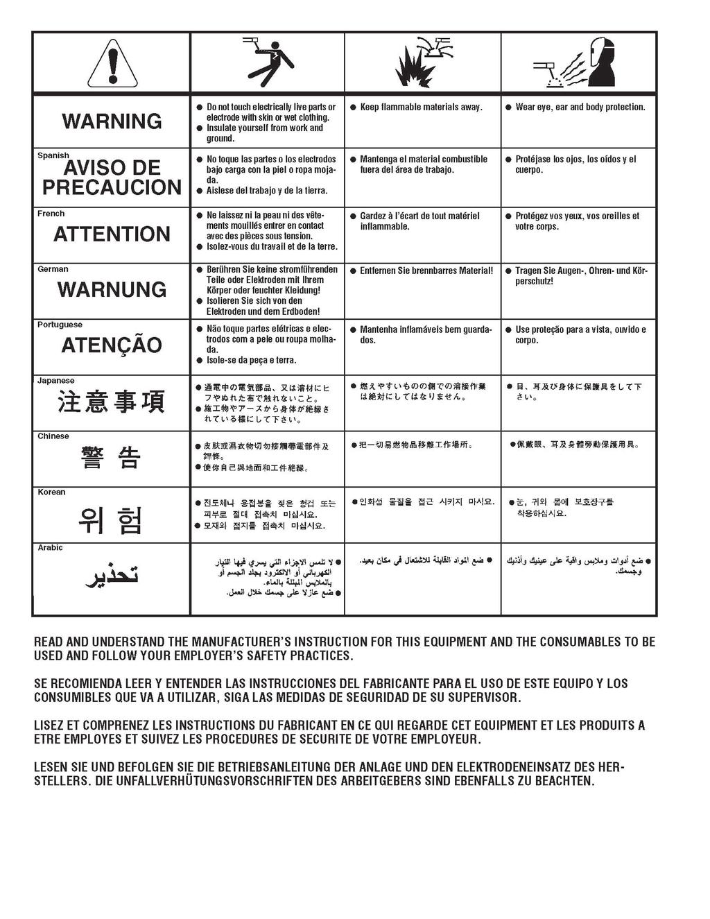
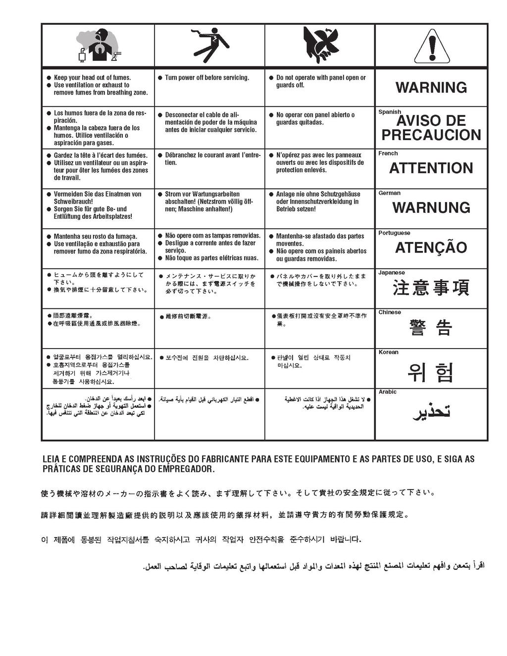
17 Operation SAFETY PRECAUTIONS WARNING! ELECTRIC SHOCK CAN KILL Do not touch electrically live parts or electrode with skin or wet clothing. Insulate yourself from work and ground Always wear dry insulating gloves WARNING! FUMES AND GASES can be dangerous Keep your head out of fumes & gases produced from welding. Use ventilation or exhaust to remove fumes & gases from breathing zone and general area. WARNING! WELDING SPARKS can cause fire or explosion Keep flammable material away from work area. Do not weld on containers that have held combustibles WARNING! ARC RAYS can burn Wear eye, ear and body protection Make sure work area is protected by proper shielding to avoid injury to passers by. Welding in MIG /MAG Mode 1 Connect the MIG Torch to machine, connect earth lead to machine & work piece. 2 Set the TIG/MMA/MIG switch to MIG 3 Select 2/4 way torch operation 4 Set Gas post flow to 1 Seconds, for special applications this can be set to max 10 seconds. 5 Select desired welding voltage 6 Select desired wire feed speed
18 Adjust wire feed speed to suit voltage/wire diameter chosen. Wire reel holder - remove retainer screw cap and fit wire reel and refit securing screw cap. The reel holder features an internal adjustable braking system so that reel of wire stops quickly when the torch trigger released, otherwise the wire reel would continue for a few seconds causing wire to come off the sides. Wire feed assembly - make sure the rollers are the correct size for the wire diameter selected. To change the rollers release the retaining knurled head screw and fit the rollers onto the shafts making sure the right size groove is in line with the wire and refit retaining screws. Do not over tighten the wire feed pressure rollers as this can cause premature motor and roller failure. TIP: Correct way to adjust tensioner is to slacken off pressure so that the wire does not feed, slowly adjust pressure until wire feeds smoothly, you should be able to stop wire feeding by holding wire and it should slip on rollers. If you have too little pressure the wire will slip when welding causing unwanted burn back into tips, if you have too much pressure wire can snag in rollers when wire hits work and cause wire tangle by rollers. Welding operation Once you have set the machine up as per above instructions press the torch trigger to start welding, gas will flow from the torch and main welding power will start and wire feed will start and once wire has touched work piece welding will start, to stop welding release torch trigger. Adjust the wire feed speed to give the desired weld characteristics More wire / Less voltage = Dip transfer Less wire / More voltage = Spray transfer Welding in TIG mode - No remote foot pedal 1 Connect the TIG torch and earth lead to machine & work piece. 2 Set the TIG/MMA/MIG switch to TIG 3 Select 2 or 4 way torch operation 4 Connect Argon gas and set flow to approx 8-12 LPM 5 Set Gas post flow to 6-10 Seconds, higher amperage requires more post flow. 6 Adjust current to desired welding current 7 Press the TIG torch switch to start welding Welding in TIG mode - with Remote foot pedal 1 Connect the TIG Torch to machine, connect earth lead to machine & work piece. 2 Connect remote foot pedal to machine 3 Set the TIG/MMA/MIG switch to TIG 4 Select 2 way torch operation 5 Connect Argon gas and set flow to approx 8-12 LPM 6 Set Gas post flow to 6-10 Seconds, higher amperage requires more post flow. 7 Press the foot pedal to start welding. Note: When welding with the remote foot pedal Upon pressing of foot pedal welding arc will start, if you find it hard to start an arc push the pedal down a bit further to aid starting
19 The benefits of welding with a remote foot pedal is that of greater control of the amount of heat going into the work - Press the pedal fully to start welding; upon weld pool formation you can slightly release the pedal to decrease the amperage to sustain a perfect weld pool and increase it again as required to sustain the weld characteristics. Welding in STICK MMA (SMAW) Mode - no remote foot pedal 1 Fit MMA electrode holder to machine 2 Fit earth lead to machine and to work piece 3 Select MMA on MMA/TIG/MIG switch 4 Place electrode in holder 5 Select desired welding current 6 Select desired Arc Force 7 Strike arc and weld Welding in STICK MMA (SMAW) Mode - with remote foot pedal 1 Fit MMA electrode holder to machine 2 Fit earth lead to machine and to work piece 3 Select MMA on MMA/TIG/MIG switch 4 Place electrode in holder 5 Select desired Arc Force 6 Connect remote foot pedal to machine 7 Select desired welding current 8 Strike arc and weld SYNERGIC AND BASIC MIG OPERATION Synergic vs. Manual Setup and Operation How Synergic MIG operates: The Synergic function of the MIG (255S) component allows the user to only need to use the wire feed speed control to make the unit operate. The welder is programmed to automatically adjust the voltage based on the users input of wire diameter and filler metal type when the wire speed is increased or decreased by turning the wire speed adjustment knob. While in the Synergic mode the user can make manual adjustment to fine tune the voltage if he chooses by turning the voltage up or down after adjusting the wire feed speed. If the wire speed is re adjusted after manual adjustment to voltage is made, the unit defaults to the synergic mode again and voltage is once again adjusted automatically. The welder may be used in full manual mode with independent control of the wire feed speed by simply selecting ALT on the wire diameter selector. Settings will not be saved when the unit cycles off and back on and will default to factory settings. If stepping away briefly it is best to keep the unit on, or the settings will not
20 remember the last settings if it is turned off. How to setup the Synergic and Manual functions: 1. Turn unit on. Wait for it to go through the power up cycle. 2. Select the MIG icon with the Process Selector button. 3. Select the wire diameter of the wire being used. Selecting ALT defaults unit to full manual mode. 4. Select the filler wire type. Fe= Steel, Al= Aluminum, SS= Stainless Steel. 5. Select 2T or 4T function. 2T is simply press and hold the torch trigger to start and activate the torch. 6. 4T requires the trigger to be pressed to start the arc. Once arc is started the trigger should be released to continue weld. The trigger should once again be pressed, held briefly and then released to terminate the arc when ready. 7. If used in the manual mode (ALT), select the appropriate wire feed speed and voltage to match wire type and size. Listen for a steady frying sound while welding to give you a key as to when it is adjusted properly. If used while in Synergic mode, select the desired wire speed and the voltage will adjust automatically. If a minor voltage adjustment is felt like it is needed while in the synergic mode, simply turn the volt-age knob to increase the voltage from the automatically selected setting. If more wire feed speed is desired, the unit will default back to the automatic setting as the wire feed speed is increased or decreased. However, manual control can once again be asserted over the automatic setting by simply turning the voltage knob once again. 8. Use the Wave Form control to select the desired arc qualities and adjust the arc qualities, whether a stiff, pen-etrating arc with a narrow bead profile and slightly more spatter, or a wider more fluid puddle that easily wets in with low amounts of spatter. Overhead welding usually requires a more stiff penetrating arc. Flat welding will accept a wider more fluid puddle. WELDING IN MIG MODE WITH SPOOL ON GUN When welding aluminium it is much simpler to use a spool on gun compared to the standard 3M MIG torch. Fit the spool on gun to euro fitting and 7 pin plug to 7 pin socket on front of machine. Fit wire spool to gun ensuring correct aluminium tips are used, you use pure argon gas for aluminium MIG welding. Select SPOOL on front panel of machine. Adjust power and wire feed to suit job and then press trigger on torch to start welding. If you experience too much splatter, increase the power or slow down wire feed speed
21 Maintenance Routine and periodic maintenance WARNING! ELECTRIC SHOCK CAN KILL Turn the input power OFF at the mains switch & fuse box before working on this equipment. Have a qualified electrician install & service this equipment. Allow machine to sit for 5 minutes minimum to allow the power capacitors to discharge before working inside this equipment. Do not touch electrically live parts 1.Periodically remove the side/top panels of machine and clean out machine with a low pressure dry air line paying particular attention to PC Boards, Fan blades. 2.Inspect input and output cables & hoses for fraying, cuts & bare spots 3.Keep tig torch and cables in good condition 4.Clean air vents to ensure proper air flow and cooling 5.The fan motor has sealed bearings which requires no maintenance Troubleshooting Service & repair should only be performed by R-Tech welding trained personnel. Unauthorized repairs performed on this equipment may result in danger to the technician and machine operator and will invalidate your warranty. For your safety and to avoid electric shock, please observe all safety notes and precautions detailed throughout this manual The troubleshooting guide is provided to help you locate possible machine malfunctions. Simply follow the 3 step procedure below Step 1 Locate problem (symptom) Look under the column labeled Problem (symptoms). This column describes possible symptoms that the machine may exhibit. Find the listing that best describes the symptom that the machine is exhibiting Step 2 Possible Cause
22 The second column labeled possible cause lists the obvious external possibilities that may contribute to the machine symptom Step 3 Recommended course of action This column provides a course of action for the possible cause, generally it states to contact R-Tech welding for repair of machine. Troubles Cause Remedy 1.Fan does not work properly 2.No indicating on the front panel 3.Over heating light on(warning led lights red or yellow color) 1.The fan connector lose 2.Fan breakage 1.The power line loose 2.Indicating light broken 3.The fuse or IGBT broken 1.Aeration is not good 2.The temperature is too high 3.Over-load use 4.Thermostat broken 1.Connect the fan connector 2.Change the fan 1.Check the power & plug 2.Change it 3.Change the fuse 5A/250Vor Contact R- Tech 1.Check grills for obstructions 2.Reduce the room temperature 3.Reduce the welding load 4.Change the thermostat(juc-of) 4.Over-current light ON (warning led lights green color) 5.Wire feeder not work ( welding current not adjustable) 6.Welding Voltage not adjustable 7.Welding stops, and warning light is on 1.IGBT broken 2.Output diode broken 3.Drive plate broken 4.Control plate broken 5.Over current welding 1.The fuse broken 2.Potentiometer wiring faulty or Potentiometer broken 3.The wire blocked 4.The drive circuit broken 5.other reasons 1.Potentiometer wiring damaged 2.Potentiometer broken 3.The circuit broken Self-protection has engaged 1.Display "801" 2.Display "802" 3.Display "804" 4.Display "805" Contact R-Tech 1.Change the fuse 5A/250V (on left panel, open wire feeder case) 2.Connect the wires or Change it 3.Check the torch liner 4.Change the control panel 5.Contact R-Tech 1.Check wiring 2.Change it 3.Change the control pcb 1.over-voltage, lower-voltage 2.over-temperature 3.over-current 4.torch switch always closed / closed circuit
23 Electrical Schematic Diagram Input AC 220V/230V/240V,rectifier and filter it into 300VDC. Control the IGBT by PWM+PFM,inverter the 300VDC to 40KHz AC. High frequency transformer pass the power by insulation and voltage reducing with high efficiency. Output the second rectifier and the second filter. Output the required welding current and voltage

24 Wiring diagram
25 - 25 -
26 - 26 -
POWER MTS210D MIG - TIG - MMA WELDING MACHINE OPERATION INSTRUCTIONS
 www.r-techwelding.co.uk email: sales@r-techwelding.co.uk Tel: 01452 733933 Fax 01452 733939 POWER MTS210D MIG - TIG - MMA WELDING MACHINE OPERATION INSTRUCTIONS Version 2014-1 2 Thank you for selecting
OPERATION INSTRUCTIONS
 www.r-techwelding.co.uk Email: sales@r-techwelding.co.uk Tel: 01452 733933 Fax: 01452 733939 ProArc 175 INVERTER ARC WELDER OPERATION INSTRUCTIONS Version 2017-10 2 3 Thank you for selecting the R-Tech
MMA 160S ARC/MMA WELDER OPERATION INSTRUCTIONS
 www.r-techwelding.co.uk MMA 160S ARC/MMA WELDER OPERATION INSTRUCTIONS 2 Thank you for selecting the R-Tech MMA160S Inverter Arc Welder. The MMA160S has many benefits over traditional Arc welders, including
OPERATION INSTRUCTIONS
 www.r-techwelding.co.uk email: sales@r-techwelding.co.uk Tel: 01452 733933 Fax 01452 733939 TIG160PDC DC TIG WELDER OPERATION INSTRUCTIONS Version 2014-1 2 Thank you for selecting the R-Tech Tig160PDC
OPERATION INSTRUCTIONS
 www.r-techwelding.co.uk Tel: 01452 733933 Fax 01452 733939 PLASMA 50HF INVERTER PLASMA CUTTER OPERATION INSTRUCTIONS Version 2014-1 2 Thank you for selecting the R-Tech PLASMA 50HF Inverter Plasma Cutter
OPERATING INSTRUCTIONS
 www.r-techwelding.co.uk email: sales@r-techwelding.co.uk Tel: 01452 733933 Fax 01452 733939 IMIG 180 PORTABLE INVERTER MIG/MAG/MMA WELDER OPERATING INSTRUCTIONS Version 2017-1 Thank you for selecting
OPERATION INSTRUCTIONS
 TIG200PDC TIG WELDER OPERATION INSTRUCTIONS 2 3 Thank you for selecting the R-Tech Tig200PDC Inverter DC Tig Welder. The Tig200PDC has many benefits over traditional tig welders, including pulse welding,
OPERATION INSTRUCTIONS
 PLASMA 30DV DUAL VOLTAGE INVERTER PLASMA CUTTER OPERATION INSTRUCTIONS 2 Thank you for selecting the R-Tech Plasma 30DV Inverter Plasma Cutter 3 The Plasma 30DV has many benefits over traditional transformer
OPERATION MANUAL M185. MIG/flux wire feeder welder. Serial Number: Where Purchase: Date of purchased:
 OPERATION MANUAL M185 MIG/flux wire feeder welder Serial Number: Where Purchase: Date of purchased: CONTENT 1. Safety... 2 2. Electrical principle drawing... 4 3. Specifications... 5 4. Front and rear
OWNER S MANUAL. Affordable Tools Achieve More. MIG140. Visit Our Website at:
 Affordable Tools Achieve More Visit Our Website at: www.uwelding.com MIG140 OWNER S MANUAL Carefully read the operation manual prior to using, installing and maintaining the electric welding machine IMPORTANT
SPEEDTEC 200C BR OPERATOR S MANUAL IM /2016 REV03 ENGLISH
 SPEEDTEC 200C BR OPERATOR S MANUAL IM3058 05/2016 REV03 ENGLISH Lincoln Electric Bester Sp. z o.o. ul. Jana III Sobieskiego 19A, 58-263 Bielawa, Poland www.lincolnelectric.eu 12/05 THANKS! For having chosen
QUATRO 450 OPERATOR S MANUAL
 QUATRO 450 OPERATOR S MANUAL IMPORTANT DO NOT INSTALL, OPERATE OR REPAIR THIS EQUIPMENT WITHOUT READING THIS MANUAL AND THE SAFETY SECTION CONTAINED INSIDE THIS MANUAL STARWELD WELDING SOLUTIONS WEBSITE:
JM-160C,JM-175C, JM-180C, JM-200C
 wilkinsonstar.com MIG Series MIG/MAG/MMA Compact welding machines Order code! JM-160C,JM-175C, JM-180C, JM-200C OPERATOR MANUAL Your new product Thank you for selecting this Jasic Technology, Wilkinson
PS MIG Volt MIG Welder Assembly & Operating Instructions
 PS07570 201205 MIG135 115 Volt MIG Welder Assembly & Operating Instructions READ ALL INSTRUCTIONS AND WARNINGS BEFORE USING THIS PRODUCT. This manual provides important information on proper operation
OPERATION MANUAL MODELS TWE-250 TWE-321 TWE-375 TRU WELD EQUIPMENT COMPANY 6400 N. HONEYTOWN ROAD SMITHVILLE, OHIO (330)
") OPERATION MANUAL MODELS TWE-250 TWE-321 TWE-375 TRU WELD EQUIPMENT COMPANY 6400 N. HONEYTOWN ROAD SMITHVILLE, OHIO 44677 (330) 669 2773 CONTENTS Section Description Pages 1 Introduction 3 2 External Features
OPERATION MANUAL MODELS TWE-250 TWE-321 TWE-375 TRU WELD EQUIPMENT COMPANY 6400 N. HONEYTOWN ROAD SMITHVILLE, OHIO 44677 (330) 669 2773 CONTENTS Section Description Pages 1 Introduction 3 2 External Features
SPEEDTEC 215C OPERATOR S MANUAL IM /2016 REV01 ENGLISH
 SPEEDTEC 215C IM3057 06/2016 REV01 OPERATOR S MANUAL ENGLISH Lincoln Electric Bester Sp. z o.o. ul. Jana III Sobieskiego 19A, 58-263 Bielawa, Poland www.lincolnelectric.eu Declaration of conformity Lincoln
LOTOS MIG175 MIG Welder
 LOTOS MIG175 MIG Welder TABLE OF CONTENTS SAFETY...... 3 SPECIFICATIONS... 8 General Description...8 What s Included.....8 Power Supply Ratings.....9 Machine Rear..10 Front Control Panel.10 Side Components...11
INVERTER AIR PLASMA CUTTING MACHINE
 INVERTER AIR PLASMA CUTTING MACHINE OPERATION MANUAL DO NOT INSTALL, OPERATE OR MAINTAIN THIS MACHINE WITHOUT READING THIS MANUAL AND PLEASE ALWAYS THINK BEFORE YOU ACT. www.hyundaiwelding.com TECHNICAL
ARC 1850 LIST OF FIGURES
 PAGE 1.0 INTRODUCTION... 1 2.0 WARRANTY... 1 3.0 UNPACKING YOUR UNIT... 1 4.0 SUGGESTED SAFETY PRECAUTIONS...... 1 4.1 PERSONAL SAFETY PRECAUTIONS. 1 4.2 POWER SUPPLY SAFETY PRECAUTIONS.. 2 5.0 GENERAL
Table of Contents Foreword I. Product Introduction II. Notice For Safety III. Main Technical Parameters IV.
 Foreword Thank you for choosing the LGK-ID IGBT Digital Air Plasma Cutter of Delixi (Hangzhou) Inverter Co., Ltd. Before use LGK-ID IGBT Digital Air Plasma Cutter, please carefully read this Manual to
WELDING INVERTER. PEGAS 160 E Smart PEGAS 200 E Smart OPERATING MANUAL. ALFA IN a.s. PEGAS E Smart Manual EN 04
 WELDING INVERTER PEGAS 160 E Smart PEGAS 200 E Smart OPERATING MANUAL PEGAS 160-200 E Smart Manual EN 04 2/12 CONTENT: 1. INTRODUCTION... 3 2. SAFETY INSTRUCTIONS AND WARNINGS... 4 3. TECHNICAL DATA...
DIGI-CUT 40PFC MV. Part No. 9030H OPERATOR S MANUAL
 DIGI-CUT 40PFC MV Part No. 9030H OPERATOR S MANUAL IMPORTANT Read this Owner s Manual completely before attempting to use this equipment. Save this manual and keep it handy for quick reference. Pay particular
PowerCRAFT TM 180i MIG
 PowerCRAFT TM 180i MIG IM7905-1 September, 2012 Rev. 01 For use with machine Part Number: PowerCRAFT TM 180i MIG K69020-1 Safety Depends on You PowerCRAFT machine is designed and built with safety in mind.
OPERATOR S MANUAL STUDPRO SERIES
 OPERATOR S MANUAL STUDPRO SERIES Capacitor Discharge Stud Welder MODELS: StudPro 2500XI StudPro 2500XIP StudPro 3125XI StudPro 3750XI CONTENTS Description Pages Safety 2 Specifications and Features 3 Product
WELDING POSITIONER OPERATION MANUAL MODEL TT-100 V1.0
 WELDING POSITIONER OPERATION MANUAL MODEL TT-100 Carefully read and understand these operation instructions before operating, inspecting, or servicing this product. This manual for use with Serial Numbers
Item #21484 XL VIEW AUTO DARKENING WELDING HELMET INSTRUCTIONS
 Item #21484 XL VIEW AUTO DARKENING WELDING HELMET INSTRUCTIONS EASTWOOD WELDING HELMETS are specifically designed to provide maximum eye and face protection from harmful UV and IR radiation emitted when
For use with machine Code POWERPLUS II 350 K POWERPLUS II 500 K
 IM7003-5 Otc, 2009 Rev. 1 POWERPLUS Ⅱ 350/500 For use with machine Code POWERPLUS II 350 K32063-1 POWERPLUS II 500 K32064-1 Safety Depends on You Lincoln arc welding and cutting equipment is designed and
14 Lincoln Electric Bester Sp. z o.o. WELD PAK /95/CEE, 2004/108/CEE
 WELD PAK 2000 IM3051 04/2015 REV02 PŘÍRUČKA UŽIVATELE (OPERATOR S MANUAL IN ENGLI) ENGLISH Lincoln Electric Bester Sp. z o.o. ul. Jana III Sobieskiego 19A, 58-263 Bielawa, Poland www.lincolnelectric.eu
PipeWorx Welding System
 PipeWorx Welding System Issued Aug. 009 Index No. PWS/.0 Multiprocess Pipe Welding Systems Quick Specs Pipe Welding Fabrication Process Piping Refinery Petrochemical Power HVAC and Water Pipe The Power
Item #21483 LARGE VIEW AUTO DARKENING WELDING HELMET INSTRUCTIONS
 Item #21483 LARGE VIEW AUTO DARKENING WELDING HELMET INSTRUCTIONS EASTWOOD WELDING HELMETS are specifically designed to provide maximum eye and face protection from harmful UV and IR radiation emitted
User s Manual. Automatic Switch-Mode Battery Charger
 User s Manual Automatic Switch-Mode Battery Charger IMPORTANT Read, understand, and follow these safety rules and operating instructions before using this battery charger. Only authorized and trained service
PowerCRAFT TM 180i MIG
 PowerCRAFT TM 180i MIG IM7905-2 July, 2014 Rev. 02 For use with machine Part Number: PowerCRAFT TM 180i MIG K69020-3 Safety Depends on You PowerCRAFT machine is designed and built with safety in mind.
MIG Welders. Operator s Manual Model 135WFG Wire Feed Welder
 Operator s Manual Model 135WFG Wire Feed Welder MIG Welders WARNING: Do not assemble, install, or operate this equipment without reading ALL of this manual and the safety precautions and warnings illustrated
OPERATOR S MANUAL StudPro LiteXI Pin Welder Stud Welding Products, Inc
 OPERATOR S MANUAL StudPro LiteXI Pin Welder CONTENTS Description Pages Safety 2 Specifications and Features 3 Product Components 4-5 Screen Operation 6-8 Setup and Welding 9-11 CD Gun Exploded View 12
OWNER S MANUAL. Affordable Tools Achieve More. LT3500. Visit Our Website at:
 Affordable Tools Achieve More Visit Our Website at: www.uwelding.com @lotostech LT3500 OWNER S MANUAL Carefully read the operation manual prior to using, Installing and maintaining the electric welding
SIP Direct Drive Oil-Lube Air Compressors - Operating & Maintenance Instructions
 SIP Direct Drive Oil-Lube Air Compressors - Operating & Maintenance Instructions Please read and fully understand the instructions in this manual before operation. Keep this manual safe for future reference.
OPERATION MANUAL MODELS TWE-250 TWE-321 TWE-375 TRU WELD EQUIPMENT COMPANY 6400 N. HONEYTOWN ROAD SMITHVILLE, OHIO (330)
") OPERATION MANUAL MODELS TWE-250 TWE-321 TWE-375 TRU WELD EQUIPMENT COMPANY 6400 N. HONEYTOWN ROAD SMITHVILLE, OHIO 44677 (330) 669 2773 Version 1.3 Date 10/20/2010 TRU WELD EQUIPMENT LIMITED WARRANTY All
OPERATION MANUAL MODELS TWE-250 TWE-321 TWE-375 TRU WELD EQUIPMENT COMPANY 6400 N. HONEYTOWN ROAD SMITHVILLE, OHIO 44677 (330) 669 2773 Version 1.3 Date 10/20/2010 TRU WELD EQUIPMENT LIMITED WARRANTY All
Transmig F: CIGWELD.COM.AU
 AUTO SET WELDING INVERTER Transmig 1300 654 674 F: 03 9474 7391 enquiries@cigweld.com.au CIGWELD.COM.AU Our customers spoke and we listened. CIGWELD have been listening to market feedback about having
Go Power! Manual. GP-1750HD Inverter GP-2500 Inverter
 Go Power! Manual GP-1750HD Inverter GP-2500 Inverter Go Power! Electric Inc. PO Box 6033 Victoria, BC V8P 5L4 Tel: 866-247-6527 Fax: 866-607-6527 Email: info@gpelectric.com Table of Contents 1. INTRODUCTION...
Caddy. Tig 2200i AC/DC. Instruction manual GB Valid for: serial no. 711-, 747-xxx-xxxx
 Caddy Tig 2200i AC/DC Instruction manual 0460 225 301 GB 20180920 Valid for: serial no. 711-, 747-xxx-xxxx TABLE OF CONTENTS 1 SAFETY... 4 1.1 Meaning of symbols... 4 1.2 Safety precautions... 4 2 INTRODUCTION...
MIG/MAG-Welding Torch Push-Pull Plus
 T e c h n o l o g y f o r t h e W e l d e r s W o r l d. MIG/MAG-Welding Torch Push-Pull Plus The versatile torch, with the Plus The Features: Fits any commercially available wire drive unit by using a
AIR COMPRESSOR OPERATING INSTRUCTION AND PARTS LIST
 AIR COMPRESSOR OPERATING INSTRUCTION AND PARTS LIST BELT TYPE IMPORTANT PLEASE MAKE CERTAIN THAT THE PERSON WHO IS TO USE THIS EQUIPMENT CAREFULLY READS AND UNDERSTANDS THESE INSTRUCTIONS BEFORE STARTING
Battery Power Inverters
 Battery Power Inverters Renogy 500W 1000W 2000W Pure Sine Wave Inverter Manual 2775 E. Philadelphia St., Ontario, CA 91761 1-800-330-8678 1 Version 1.4 Important Safety Instructions Please save these instructions.
OWNER S OPERATING MANUAL
 OWNER S OPERATING MANUAL MIG 100 GASLESS WELDER TABLE OF CONTENTS Page Safety instructions 3-4 MIG Welders 5 Welder Information 5 Gasless welder set up 6 Operation 6-10 Troubleshooting Guide 11-12 Spare
NSGV PT-1000 PORTABLE WELDING STATION I, O & M MANUAL
 APPLICATION OF DUST CONTROL EQUIPMENT: CAUTION - Warning Improper operation of dust control system may contribute to conditions in the work area or facility that could result in severe personal injury
Cutlass Fasteners, Inc. 83 Vermont Ave., Unit 6, Warwick, RI Tel: (401) Fax: (401) cutlass-studwelding.com
 Fax: (401) cutlass-studwelding.com") MODEL : BANTAM C8 PART NO. : 602-325P SERIAL NO. : PLEASE READ THIS OPERATION AND MAINTENANCE MANUAL CAREFULLY BEFORE USING YOUR NEW CUTLASS STUD WELDER. COPYRIGHT CFI 2009 email: sales@ PAGE - 1 - WARRANTY
MODEL : BANTAM C8 PART NO. : 602-325P SERIAL NO. : PLEASE READ THIS OPERATION AND MAINTENANCE MANUAL CAREFULLY BEFORE USING YOUR NEW CUTLASS STUD WELDER. COPYRIGHT CFI 2009 email: sales@ PAGE - 1 - WARRANTY
BATTERY BOOSTER/CHARGER MODEL NO: DIGICAR 600
 BATTERY BOOSTER/CHARGER MODEL NO: DIGICAR 600 PART NO: 6261200 OPERATION & MAINTENANCE INSTRUCTIONS LS0815 INTRODUCTION Thank you for purchasing this CLARKE Battery booster / charger which is suitable
WELDING HELMET INSTRUCTIONS. Part #20520
 WELDING HELMET INSTRUCTIONS Part #20520 EASTWOOD WELDING HELMETS are specifically designed to provide maximum eye and face protection from harmful UV and IR radiation emitted when welding, in a lightweight,
POWERTEC 205C, 255C & 305C
 POWERTEC 205C, 255C & 305C OPERATOR S MANUAL IM3021 09/2016 REV03 ENGLISH Lincoln Electric Bester Sp. z o.o. ul. Jana III Sobieskiego 19A, 58-263 Bielawa, Poland www.lincolnelectric.eu Declaration of conformity
INSTRUCTION MANUAL FOR PLASMA CUTTER
 INSTRUCTION MANUAL FOR PLASMA CUTTER IMPORTANT: BEFORE STARTING THE EQUIP- MENT, READ THE CONTENTS OF THIS MANUAL, WHICH MUST BE STORED IN A PLACE FAMILIAR TO ALL USERS FOR THE ENTIRE OPERATIVE LIFE-SPAN
MODEL NUMBER: MEDIUM DUTY ONBOARD AIR SYSTEM
 MODEL NUMBER: 10003 MEDIUM DUTY ONBOARD AIR SYSTEM IMPORTANT: It is essential that you and any other operator of this product read and understand the contents of this manual before installing and using
Quick Draw Spool Gun OWNER S MANUAL
 Quick Draw Spool Gun OWNER S MANUAL WARNING: Read carefully and understand all ASSEMBLY AND OPERATION INSTRUCTIONS before operating. Failure to follow the safety rules and other basic safety precautions
OPERATOR S MANUAL. TW-i SERIES. Capacitor Discharge Stud Welder. MODELS: TW-i 250 TW-i 250CP TW-i 321 TW-i 375
 OPERATOR S MANUAL TW-i SERIES Capacitor Discharge Stud Welder MODELS: TW-i 250 TW-i 250CP TW-i 321 TW-i 375 TRU-WELD EQUIPMENT COMPANY www.truweldstudwelding.com (330) 725-7744 CONTENTS Description Pages
BATTERY BOOSTER/CHARGER MODEL NO: DIGICAR 900
 BATTERY BOOSTER/CHARGER MODEL NO: DIGICAR 900 PART NO: 6261205 OPERATION & MAINTENANCE INSTRUCTIONS LS0715 INTRODUCTION Thank you for purchasing this CLARKE Battery booster / charger which is suitable
CFT24 &CFT230 PART NOS:
 FUEL TRANSFER PUMP Model Nos. CFT12, CFT24 &CFT230 PART NOS: 7160010, 7160020 & 7160030 INSTALLATION & OPERATING INSTRUCTIONS ORIGINAL INSTRUCTIONS GC05/18 REV 5 INTRODUCTION Thank you for purchasing this
ADVANCEMIG Digital Synergic Inverter MIG/MMA/TIG Welder PFC MV 200 Amps
 ADVANCEMIG 200 - Digital Synergic Inverter MIG/MMA/TIG Welder PFC MV 200 Amps ORDER CODE: Ex GST Inc GST $2,194.00 $2,523.10 W1107 MODEL: ADVANCEMIG 200 Type: MIG / TIG / MMA & Multifunction Part Number:
Model: OBD-L On-Board-Diagnostics II Memory Saver Detector
 Model: OBD-L On-Board-Diagnostics II Memory Saver Detector OWNERS MANUAL IMPORTANT SAFETY INSTRUCTIONS SAVE THESE INSTRUCTIONS This manual will show you how to use your memory saver detector safely and
OPERATING INSTRUCTIONS. Note: 6V Charging. Requires Manual Shut Off.
 Requires Manual Shut Off. 6 / 2 AMP,, DUAL RATE BATTER TTERY CHARGER 45005 OPERATING INSTRUCTIONS E224783 E224783 Note: 6V Charging Due to continuing improvements, actual product may differ slightly from
MIG WELDER 131 ASSEMBLY AND OPERATING INSTRUCTIONS Mission Oaks Blvd., Camarillo, CA Visit our Web site at
 MIG WELDER 131 06098 ASSEMBLY AND OPERATING INSTRUCTIONS 3491 Mission Oaks Blvd., Camarillo, CA 93011 Visit our Web site at http://www.harborfreight.com Copyright 2003 by Harbor Freight Tools. All rights
Pure Sine Wave Inverter GP-HS1500. Owner s Manual
 Pure Sine Wave Inverter GP-HS1500 Owner s Manual 2 Table of Contents Introduction 3 Specifications 4 Name and Main Function 5 Installation 7 Operation 9 Operating Limits 13 Troubleshooting 13 Maintenance
GMAW FCAW. 5Year * Fabricator 281 comes with:
 Fabricator 28 C DC 208 Power, Performance, Features... and Reliability 5Year * Quick Specifications Processes MIG () Flux Cored () Industrial Applications Maintenance and Repair Garage/Body Shops Fabrication/Construction
For use with machine Code POWERPLUS II 350 K / POWERPLUS II 500 K / 76097
 IM7003-1 April, 2011 Rev. 3 POWERPLUS Ⅱ 350/500 For use with machine Code POWERPLUS II 350 K60039-1 / 76095 POWERPLUS II 500 K60040-1 / 76097 Safety Depends on You Lincoln arc welding and cutting equipment
OPERATION/ MAINTENANCE MANUAL
 208 VERSION OPERATION/ MAINTENANCE MANUAL TABLE OF CONTENTS Section 1 SAFETY PRECAUTIONS PAGE 1.0 INTRODUCTION... 1 2.0 WARRANTY... 1 3.0 UNPACKING YOUR UNIT... 1 4.0 SUGGESTED SAFETY PRECAUTIONS... 1
OPERATION MANUAL. TWE Pin Welder. Model TWP-2 TRU WELD EQUIPMENT COMPANY 6400 N. HONEYTOWN ROAD SMITHVILLE, OHIO (330) Revision 2.
 Revision 2.") OPERATION MANUAL TWE Pin Welder Model TWP-2 TRU WELD EQUIPMENT COMPANY 6400 N. HONEYTOWN ROAD SMITHVILLE, OHIO 44677 (330) 725 7744 Revision 2.0 8/22/2013 TRU WELD EQUIPMENT LIMITED WARRANTY All goods
OPERATION MANUAL TWE Pin Welder Model TWP-2 TRU WELD EQUIPMENT COMPANY 6400 N. HONEYTOWN ROAD SMITHVILLE, OHIO 44677 (330) 725 7744 Revision 2.0 8/22/2013 TRU WELD EQUIPMENT LIMITED WARRANTY All goods
MODEL 6010A 6 12 VOLT BATTERY CHARGER ASSOCIATE
 MODEL 600A 6 VOLT BATTERY CHARGER ASSOCIATE IMPORTANT SAFETY INSTRUCTIONS. SAVE THESE INSTRUCTIONS. This manual contains important safety and operating instructions for the battery charger you have purchased.
OPERATION MANUAL TWE-375 CAPACITOR DISCHARGE WELDER
 OPERATION MANUAL TWE-375 CAPACITOR DISCHARGE WELDER TRU WELD EQUIPMENT COMPANY 6400 N. HONEYTOWN ROAD SMITHVILLE, OHIO 44677 (330) 725 7744 TWE@tfpcorp.com Version 1.0 Date 8/13/2013 TRU WELD EQUIPMENT
HD 7700 Setup & Operator Manual
 HD 7700 Setup & Operator Manual Issue 1 December, 01 Performance Design Inc. The Heavy Duty Ultima (HD 7700) electric punch has been designed to punch most any job that may pass through your bindery or
VIPER MIG-MMA Welder Package Amps #KUMJRVW182 $ $ Product Brochure For K019A. Description. Features
 VIPER 182 - MIG-MMA Welder Package 30-180 Amps #KUMJRVW182 Package Deal Ex GST Inc GST $530.00 $583.00 Package Contents - SAVE $51.50 (Inc) 1 x W244 - VIPER 182 Multi-Function Inverter Welder-MIG-MMA $519.00
Processes MIG (GMAW) Pulsed MIG (GMAW-P) Flux-cored (FCAW) DC stick (SMAW) DC Lift-Arc TIG (GTAW) Pulsed TIG (GTAW-P)
 Pulsed MIG (GMAW-P) Flux-cored (FCAW) DC stick (SMAW) DC Lift-Arc TIG (GTAW) Pulsed TIG (GTAW-P)") Multimatic 255 MIG/Multiprocess Power Source, Wire Feeder and Gun Package Issued Nov. 2018 Index No. DC/12.9 Quick Specs Industrial Applications Contract welding services Plant maintenance shops General
Multimatic 255 MIG/Multiprocess Power Source, Wire Feeder and Gun Package Issued Nov. 2018 Index No. DC/12.9 Quick Specs Industrial Applications Contract welding services Plant maintenance shops General
MTS 200 User Manual TSX1D200MTS SWMTS001
 MTS 200 User Manual SWMTS001 DECLARATION OF CONFORMITY The Low voltage Directive 2006/95/EC of 12 December 2006, entering into force 16 January 2007 Type of Equipment Welding power source for MIG/MAG,
OWNER S OPERATING MANUAL
 OWNER S OPERATING MANUAL ARC 140 AMP WELDER TABLE OF CONTENTS Page Safety instructions 3-4 Inverter Arc Welder 5 Welder Information 5 Arc 140 AMP welder set up 6 Assembly instructions 6 Operation 7 Welding
Cutlass Fasteners, Inc. 83 Vermont Ave., Unit 6, Warwick, RI Tel: (401) Fax: (401) cutlass-studwelding.com
 Fax: (401) cutlass-studwelding.com") MODEL : BANTAM C8 BANTAM C10 PART NO. : 602-325A 602-343A SERIAL NO. : PLEASE READ THIS OPERATION AND MAINTENANCE MANUAL CAREFULLY BEFORE USING YOUR NEW CUTLASS STUD WELDER. COPYRIGHT CFI 2009 email: sales@
MODEL : BANTAM C8 BANTAM C10 PART NO. : 602-325A 602-343A SERIAL NO. : PLEASE READ THIS OPERATION AND MAINTENANCE MANUAL CAREFULLY BEFORE USING YOUR NEW CUTLASS STUD WELDER. COPYRIGHT CFI 2009 email: sales@
HOT WASHER MODEL NO: KING 125 OPERATION & MAINTENANCE INSTRUCTIONS PART NO: LS1009
 HOT WASHER MODEL NO: KING 125 PART NO: 7320170 OPERATION & MAINTENANCE INSTRUCTIONS LS1009 INTRODUCTION Thank you for purchasing this Hot Washer. This machine is a portable, high pressure power washer,
Part #20279 MIG 250 WELDER ASSEMBLY & OPERATING INSTRUCTIONS
 Part #20279 MIG 250 WELDER ASSEMBLY & OPERATING INSTRUCTIONS PDF version available at eastwood.com/20279manual STATEMENT OF LIMITED WARRANTY The Eastwood Company (hereinafter Eastwood ) warrants to the
OPERATOR S MANUAL ACE - P100
 OPERATOR S MANUAL ACE - P100 Pin Welder TRU-WELD EQUIPMENT COMPANY www.truweldstudwelding.com (330) 725-7744 CONTENTS Description Pages Warranty Information 1 Safety 2 Specifications and Features 3 Product
POWER PINNER CD HAND WELDER 7300 OPERATOR S MANUAL
 POWER PINNER CD HAND WELDER 7300 OPERATOR S MANUAL Copyright: April 7, 2014 Gripnail Corporation Revised: January 25, 2018 An Employee Owned Company 97 Dexter Road East Providence, Rhode Island 02914-2045
MULTIVOLTAGE PORTABLE BATTERY CHARGER MVM
 _ M MULTIVOLTAGE PORTABLE BATTERY CHARGER MVM User's MANUAL Code: MVM Version: 01-BF Date: OCT 2005 Page 1/10 _ 1. INTRODUCTION Before starting to use your Energic plus MVM battery charger, please take
Improves Safety, Productivity & Profitability.
 Improves Safety, Productivity & Profitability. TM GAME-CHANGING TECHNOLOGIES CAN STOP YOU FROM WASTING HOURS EVERY DAY. ArcReach welding technology minimises the non-valueadded time spent walking to and
Stick/Mig Capability Welding Excellence Modular Construction Environment Protected 2,000 Watt AC Power for Tools
 E300 3+2 Electric Welder Service Manual Stick/Mig Capability Welding Excellence Modular Construction Environment Protected 2,000 Watt AC Power for Tools SVM_E300 3+2 SAFETY Arc Welding Safety Precautions
GSL Electronics Modified Sine Wave Power Inverters
 GSL Electronics Modified Sine Wave Power Inverters Congratulations on choosing one of our Modified Sine Wave Inverters for your application. There are 6 models in the range, which will meet most of your
Model: SPTOGT01 TRACTOR PTO GENERATOR
 www.scintex.com.au sales@scintex.com.au Model: SPTOGT01 TRACTOR PTO GENERATOR SET UP, OPERATING, AND SERVICING INSTRUCTIONS Read this material before using this product. Failure to do so can result in
MIG/Stick/TIG MP200iDV LCD 200 Amp
 MIG/Stick/TIG MP200iDV LCD 200 Amp Dual Voltage Multi-Process Welder Owner s Manual WARNING: Read carefully and understand all ASSEMBLY AND OPERATION INSTRUCTIONS before operating. Failure to follow the
1000 Watt Power Inverter INSTRUCTION MANUAL HT87112-AUOXY
 1000 Watt Power Inverter INSTRUCTION MANUAL HT87112-AUOXY CONTENTS Warranty 2 Introduction 3 Environmental protection 3 Specifications 3 General safety warnings and instructions 4 Important safety instructions
MINI MIG MIG Welder Amps
 MINI MIG 180 - MIG Welder 35-180 Amps #KMM180 ORDER CODE: W240 MODEL: MINI MIG 180 Type: MIG Part Number: KMM180 Voltage (V): 240 Recommended Plug Amperage (amp): 15 Welding Current Range MIG (amp): 35-180
OPERATION MANUAL. Model TWP-2. Toll free customer support:
 OPERATION MANUAL TWE StudPro Pin Welder Lite Model TWP-2 Downey, CA 9459 Washburn Rd. Downey, CA 90242 Phone- 800.252.1919 Fax- 562.862.3022 Hayward, CA Phoenix, AZ 2391 American TRU WELD Ave. EQUIPMENT
R5000/4000 CV INSTRUCTION MANUAL. Important Information. Description. Processes. Constant Voltage Power Source
 R5000/4000 CV Description Constant Voltage Power Source Processes Important Information All persons authorised to use, repair or service the R4000/R5000 Inverter welding unit, should read the section on
MMWTIG241I OWNER S MANUAL
 MMWTIG241I OWNER S MANUAL WARNING: Read carefully and understand all ASSEMBLY AND OPERATION INSTRUCTIONS before operating. Failure to follow the safety rules and other basic safety precautions may result
MERKLE OptiMIG. The MIG/MAG Industrial series! MIG/ MAG
 MERKLE OptiMIG. The MIG/MAG Industrial series! MIG/ MAG www.merkle.de MIG/ MAG Merkle OptiMIG MIG/MAG series OptiMIG The series OptiMIG 350/450/550 consists of step controlled MIG/MAG welding units from
EVERLAST POWER MTS 200/250S
 EVERLAST POWER MTS 200/250S CC/CV MULTI-PROCESS WELDER GMAW/GTAW/SMAW CC CV GMAW GTAW SMAW IGBT DC Operator s Manual for the Power MTS 200/250S Safety, Setup and General Use Guide everlastwelders.com 1-877-755-9353
Semi-Automatic Wire Feeders. Semi-Automatic Contents Wire Feeders. Equipment
 Semi-Automatic Contents Wire Feeders Semi-Automatic Wire Feeders LF-72 & LF-74 LN-742 LN-8 LN-9 LN-10 DH-10 Power Feed TM 25M Power Feed TM 10M Power Feed TM 10M Dual LN-23P LN-25 Page 2 Page 3 Page 4
Go Power! Manual. GP-SW1500 Inverter. Table of Contents. Go Power! Electric Inc. PO Box 6033 Victoria, BC V8P 5L4
 Table of Contents 1. INTRODUCTION... 3 Go Power! Manual GP-SW1500 Inverter 2. SPECIFICATIONS... 3 3. NAME AND MAIN FUNCTION... 3 4. INSTALLATION... 5 5. OPERATION... 7 6. OPERATING LIMITS... 9 7. TROUBLESHOOTING...
OWNER S OPERATING MANUAL
 OWNER S OPERATING MANUAL MIG/TIG/ARC 200 ELECTRONIC INVERTER INVERTER MULTITASK TABLE OF CONTENTS Safety instructions 3-4 Multitask 200 Welder 5 Page Installation 6 Welder Information 6-8 Control panel
HQST 500W (12V) HQST 1000W (12V) Modified Sine Wave Inverter. User Manual
 HQST 1000W (12V) Modified Sine Wave Inverter. User Manual") HQST 500W (12V) HQST 1000W (12V) Modified Sine Wave Inverter User Manual Important Safety Instructions Please read the installation and operating instructions in this manual carefully before using your
HQST 500W (12V) HQST 1000W (12V) Modified Sine Wave Inverter User Manual Important Safety Instructions Please read the installation and operating instructions in this manual carefully before using your
WFU12A-RV INSTRUCTION MANUAL. Important Information. Description. Processes. Wire Feed Unit
 Description Wire Feed Unit Processes Important Information All persons authorised to use, repair or service the wire feed unit, should read the section on safety, before any work is undertaken. Further
Transmatic 4C. Instruction manual and spare parts list
 GB Transmatic 4C Instruction manual and spare parts list 0459 706 074 090514 Valid for serial no. 435 -xxx -xxxx 1 DIRECTIVE... 3 2SAFETY... 3 3 INTRODUCTION... 4 3.1 Equipment... 5 4 TECHNICAL DATA...
OWNER S OPERATING MANUAL
 OWNER S OPERATING MANUAL WELD AND CUT ARC/TIG INVERTER PLASMA 30 PLASMA CUTTER TABLE OF CONTENTS Safety instructions 3-4 Weld & Cut ARC/TIG and Plasma Cutter 5 Page Installation 6 Welder Information 6-8
TURNING ROLLS 00338OG WARNINGS, SAFEGUARDS & OPERATING INSTRUCTIONS
 TURNING ROLLS 00338OG091207 WARNINGS, SAFEGUARDS & OPERATING INSTRUCTIONS Warnings and Safeguards for Welding and Cutting Operations IMPORTANT - Protect yourself and others! Remember that safety depends
Processes MIG (GMAW) Pulsed MIG (GMAW-P) Flux-cored (FCAW) DC stick (SMAW) DC Lift-Arc TIG (GTAW) Pulsed TIG (GTAW-P)
 Pulsed MIG (GMAW-P) Flux-cored (FCAW) DC stick (SMAW) DC Lift-Arc TIG (GTAW) Pulsed TIG (GTAW-P)") Multimatic 255 MIG/Multiprocess Power Source, Wire Feeder and Gun Package Issued January 2019 Index No. DC/12.9 Quick Specs Industrial Applications Contract welding services Plant maintenance shops General
Multimatic 255 MIG/Multiprocess Power Source, Wire Feeder and Gun Package Issued January 2019 Index No. DC/12.9 Quick Specs Industrial Applications Contract welding services Plant maintenance shops General
2603 Battery Pal 3 AMP, 1 2 VOLT BATTERY CHARGER
 R 2603 Battery Pal 3 AMP, 1 2 VOLT BATTERY CHARGER Connections at a glance: The GUEST Battery Pal 2603 is designed to recharge your battery, and extend your battery s life in applications where it is stored
Inverter Welding System
 POWER WAVE 455/STT AND POWER FEED 10 DUAL Inverter Welding System NEW! POWER WAVE 455/STT AND POWER FEED 10 DUAL ADVANTAGE LINCOLN HIGHEST PERFORMANCE SYSTEM Superior STT, pulsed GMAW and FCAW welding