R5000/4000 CV INSTRUCTION MANUAL. Important Information. Description. Processes. Constant Voltage Power Source
|
|
|
- Joseph Hodges
- 5 years ago
- Views:
Transcription

 191 295 0111 Aberdeen +44 (0) 1224 771 063 www.newarc.co.")
1 R5000/4000 CV Description Constant Voltage Power Source Processes Important Information All persons authorised to use, repair or service the R4000/R5000 Inverter welding unit, should read the section on safety, before any work is undertaken. Further information is available in publication HSG118 'Electric safety in arc welding', which may be obtained from the Health & Safety Executive. Please contact your distributor should you not understand any of the information within this document. INSTRUCTION MANUAL Newarc Equipment Ltd. UK s Leading Manufacturer Of Welding Equipment Newcastle +44 (0) Aberdeen +44 (0) To maintain continued developments of our products we reserve the right to alter specifications as quoted without prior notice
2
3 TABLE OF CONTENTS SECTION 1 SAFETY 1.1 General Precautions 4 SECTION 2 SPECIFICATION Specification 5 SECTION 3 INSTALLATION Siting the R5/ Connecting to mains supply Setting supply voltage tapping 6 SECTION 4 OPERATION Operating Controls 7 SECTION 5 FAULT FINDING AND MAINTENANCE MIG Welding Problems Maintenance 9 SECTION 6 ELECTRICAL DIAGRAMS System Diagram 10 SECTION 7 PARTS BREAKDOWN Component Locations Parts List 13
4 SECTION 1 SAFETY 1.1 Fire and Explosions Pay attention to fire and safety regulations in force at the welding site. Remove all flammable or combustible materials from the welding area and the immediate vicinity. Suitable fire fighting equipment must always be present where welding is carried out. Be aware that a fire risk is present for a considerable time after welding operations have ceased because of sparks and hot slag etc. Take suitable precautions when you have finished welding. Take care when welding containers that have held flammable or combustible material, these should have been specially cleaned before being given to the welder. If in any doubt do not attempt to weld them. 1.2 Burns Be aware that burns may be the result of the heat involved in the welding process, welding spatter or the Ultra Violet Radiation given off by the arc itself. Wear suitable fireproof clothing over all your body. Wear protective gauntlets designed for welding use. Wear a welding facemask fitted with the correct filter shade suitable for the current at which you will be welding. Avoid wearing oily or greasy clothing as a spark may ignite them. Where possible ensure that a suitable first aid kit and a first aid person qualified in the treatment of burns are available nearby. 1.3 Fumes Welding operations give off harmful fumes that are hazardous to your health. Make sure the welding area is well ventilated. Use suitable fume extractors or exhaust fans if necessary. If the ventilation is not suitable then breathing apparatus may have to be used. Do not weld plated metals or metals which contain Lead, cadmium, Zinc, Mercury or Beryllium unless you are wearing suitable breathing apparatus. 1.4 Electric Shock Do not touch live electrical parts. Do not work in wet or excessively humid areas and do not site the unit on a wet surface. Avoid touching the work piece whilst welding. Do not use the unit without the protective cover. Keep your clothing and body dry. 1.5 The safe handling of gas cylinders Gas cylinders are under pressure and can explode if punctured. Please ensure the cylinder is secured in a stable location, away from any heat source or potential mechanical damage. The cylinder must be securely fastened to a wall or placed in a specially designed cylinder carrier. Do not use gas cylinders whose contents you are unsure of. Do not try to directly connect a gas cylinder to Newarc equipment without using a pressure-reducing regulator designed for use with argon. Always install and use pressure regulators in accordance with the manufacturers instructions. It is advisable, when attaching the regulator to the gas bottle, to briefly turn on the bottle valve to expel any foreign objects that may be present. These may later block the solenoid valve of the machine if not dealt with. Turn your face away from the bottle valve when undertaking this action. Check the gas cylinder, pressure regulator and gas hoses regularly for leaks and discard any suspect item. Always turn off the valve on the gas cylinder when you have finished welding. Further information is available in publication HSG118 'The safe use of compressed gases in welding, flame cutting and allied processes', which may be obtained from the Health & Safety Executive. 1.6 Welding and earth return cables Earth return and interconnecting power cables must have a cross sectional area of at least 35mm 2. Only use copper cables, the use of Aluminium cables may have a detrimental effect on the performance of the machine. Regularly inspect welding cables and connectors for wear abrasion and corrosion. Corroded cables and connectors may overheat and become a fire hazard. Ensure that all welding connectors are fully mated, the connectors should be pushed fully home and then turned clockwise to lock. If the connectors are not mated fully they may overheat and become a fire hazard. If possible, fasten the earth return clamp directly to the job to be welded and ensure that the surface is free from rust and paint.
5 SECTION 2 SPECIFICATION Specification Description These heavy duty D.C inverter power sources have been designed using the latest developments in power electronics. Electronic parts are enclosed in a separate sealed compartment for protection from the environment. This portable, versatile inverter power source responds to changes in the welding arc much faster than conventional machines resulting in a more stable and controllable weld pool. Due to the high efficiency and power factor these units provide energy and cost saving solutions. The R4000CV/R5000CV is capable of MIG welding when used with a peripheral wire feed unit. Technical data R4000 R5000 Models Available Volts 3 Phase Volts 3 Phase Input Current at Max Output 24 amps 33 amps Power Consumption 18.5 KVA 25 KVA Recommended Mains Fuse 32A slow blow or type C MCB 40A slow blow or type C MCB Mains Cable 4 x 4.0mm² flexible cable 4 x 4.0mm² flexible cable Power Factor Max Output Current 400 amps 500 amps Open Circuit Voltage 40V 50V Voltage Control 2-40V Infinitely Variable 2-50V Infinitely Variable Duty Cycle at 40ºC 70% 70% Degree of Protection IP23 IP23 Insulation Class F F H x W x L (mm) 445 x300x x300x530 Weight (kg) 30 33

6 SECTION 3 INSTALLATION 3.1 Siting the R4000/R5000 Site the R4000/R5000 on a clean dry surface, preferable above ground level. Make sure there is at least 20cm clearance at the front, rear and right side of the machine to allow good circulation of the cooling air. Protect the machine from heavy rain and if used in hot climates, against direct sunlight. Ensure that the machine is positioned in such a way that particles created by grinding and cutting operations do not enter the machine. Note! Damage caused by metal particles and water entering the machine will not be covered under warranty. 3.2 Connecting to mains supply WARNING! All electric shocks are potentially fatal, a competent electrician should carry out the fitting of the mains plug. Make sure that the mains supply is of the correct voltage and current capability for the machine. Make sure that any extension cables used are of sufficient current carrying capacity. Make sure that the mains plug and socket (if fitted) are in good condition and are of the correct current carrying capacity. If the machine is wired directly to the mains supply then an isolator switch must be fitted. Note! See the technical specifications page for correct supply information Primary cable length Long cable lengths may reduce the performance of the machine, the welding arc may become unstable, especially at higher currents. Ensure the mains cable is not coiled up during welding as this will reduce the input voltage to the machine and may cause overheating and degradation of the cable. 3.3 Setting supply voltage tapping WARNING! All electric shocks are potentially fatal, a competent electrician should carry out any supply voltage tapping adjustments required. To enable the setting of the supply voltage tapping, the front panel display cover of the R4000/R5000 has to be removed. The photograph below shows the voltage tapping set to 415V, with the red wire from the fuse holder connected to the 415 terminal. This connector can be moved to the required voltage terminal to select the desired input voltage.

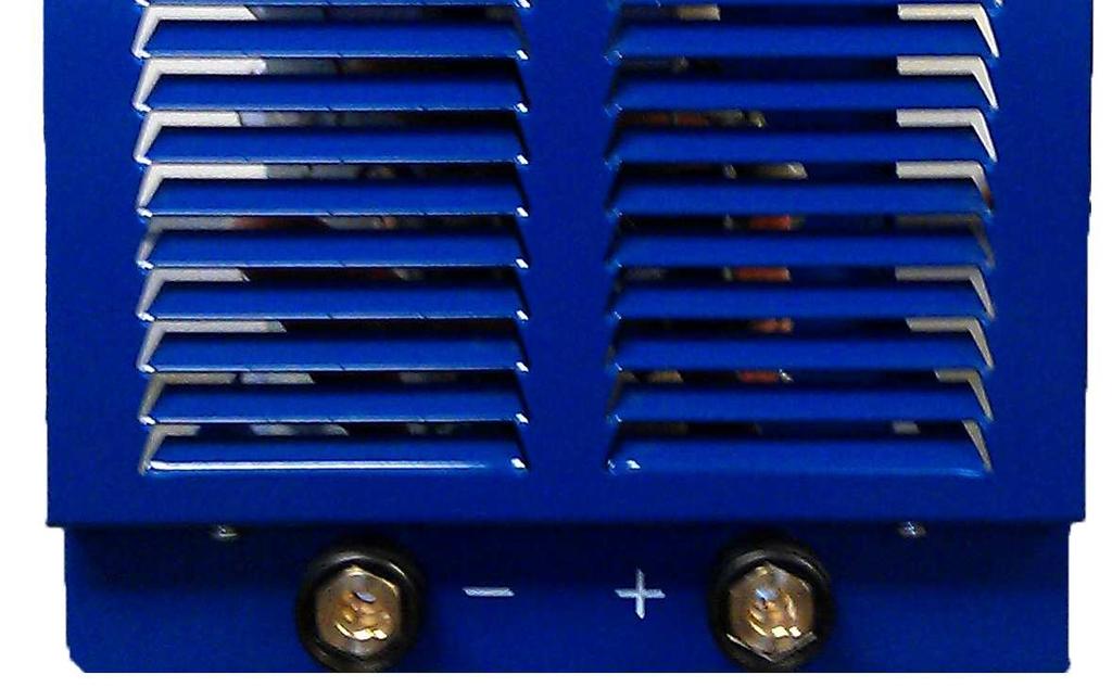
7 SECTION 4 OPERATION Description of controls 1. Digital Display - Indicates welding current in Amps, welding voltage in Volts and gives an indication when the machine is over temperature. 2. Standby switch - Switches the machine on and off when the main 3 Phase isolation switched is in the on position. Upon switching on, the display will read 4000 or 5000 and the machines output will be inhibited. After 4 seconds the display will clear and the machine is ready to use. 3. Inductance control - Used to refine the arc condition and reduce spatter. 4. Remote control socket - For connection of external remote control or wire feed unit. There is no switch for remote operation, plugging an external unit into the socket automatically selects remote operation and disables the internal current control. 5. Slope control - Used to compensate for voltage drop on long welding cables. 6. -ve weld terminal - Main welding power output connector, negative polarity. 7. +ve weld terminal - Main welding power output connector, positive polarity. 8. Auxiliary supply fuse - protects the auxiliary supply from the remote control socket. Fuse type is 20 x 5mm glass body, 6.3A slow blow rating. 9. Main 3P Isolation switch - Switches the machine on and off. 10. Main supply fuse - Fuse 3.15A slow blow, 32 x 6.3mm ceramic body. 11. Mains Input - Three phase mains cable
8 SECTION 5 FAULT FINDING AND MAINTAINANCE 5 Fault finding and maintenance 5.1 Machine operation Most problems with the R4000/R5000 can be overcome by following the procedures below. No Digital Display on switch on. Check that the machine is attached to a working mains supply that it is correctly plugged in and any isolator switches are closed. Check the condition of the 2A fuse on the rear panel of the machine and replace if necessary. Note : make sure the fuse is replaced with one of the correct type and rating. It should be a 32 x 6.3mm (1¼ x ¼ ) ceramic bodied type with a rating of 2A slow blow Have a competent electrician check that there are no mains fuses or overload devices interrupted, that the mains plug is fitted correctly and that there are no loose wires or connections, check that there are no breaks in the mains cable. Digital display lit but no output. Make sure that the display is not reading OT, if it is, it means that the R4000/R5000 has overheated, normally by exceeding its Duty Cycle, and the power stages of the machine have been shut down. In this case, leave the machine switched on until it has cooled down, if you turn the machine off, the cooling fans will be turned off lengthening the cooling down period considerably. Note : If the R4000/R5000 is overheating on a regular basis or at current settings below the maximum, this would usually indicate that the inside of the machine is choked with dust and therefore not being cooled correctly. For information about cleaning the dust out of the R4000/R5000 please refer to the relevant part of section 5.3.2, the three monthly service schedule. MIG Unit is not working. Check the condition of the 6.3A fuse on the rear panel of the machine and replace if necessary. Note : make sure the fuse is replaced with one of the correct type and rating. It should be a 20 x 5mm glass bodied type with a rating of 6.3A slow blow. 5.2 Welding Problems If problems are experienced whilst MIG welding, please consult the fault finding and maintenance section of the WFU instruction manual. Any welding problems not covered above must be brought to the attention of a qualified Welding Engineer, if the problem still persists the R4000/R5000 should be checked by a trained New-Arc service engineer.
9 SECTION 5 FAULT FINDING AND MAINTAINANCE 5.3 Maintenance Note! All Electric shocks are potentially fatal, switch off the machine and unplug from the mains supply before carrying out any maintenance work. It is very important that the R4000/R5000 is regularly maintained. The amount of use and the working environment must be taken into account when scheduling the maintenance periods. Careful use and regular preventative maintenance will prolong the life of the machine and ensure trouble free operation Weekly Clean the exterior of the machine Inspect the machines exterior for obvious signs of damage. Check the condition of the welding cable, earth clamp and welding output connectors for damage and any sign of over-heating Check the condition of the mains cable and plug Three monthly As per the weekly schedule, plus:- Remove the lid from the machine and remove the build up of dust and debris from inside the machine using, either, compressed air at low pressure or an industrial type vacuum cleaner. Make a thorough visual inspection of the interior of the machine, look particularly for pieces of welding wire that may have got through the cooling air intakes. Check the condition of the mains input connector, look for loose terminal block screws and make sure the sheath of the mains cable is still clamped securely in the combined cable entry/clamp. Make sure the earth wire is still securely fastened to the earth stud. Check the condition of the welding output connectors, look for any signs of discoloration due to overheating, this is generally caused by poor connection of the welding power leads due to loose connection bolts inside the set, or poor quality welding connectors on the electrode holder or earth return lead and can be a common cause of welding set failure Annually As per the three monthly schedule, plus :- The machines calibration should be checked, if necessary have the machine re-calibrated by a New- Arc trained technician.
10 SECTION 6 ELECTRICAL DIAGRAMS System Diagram


11 SECTION 7 PARTS BREAKDOWN Component Locations


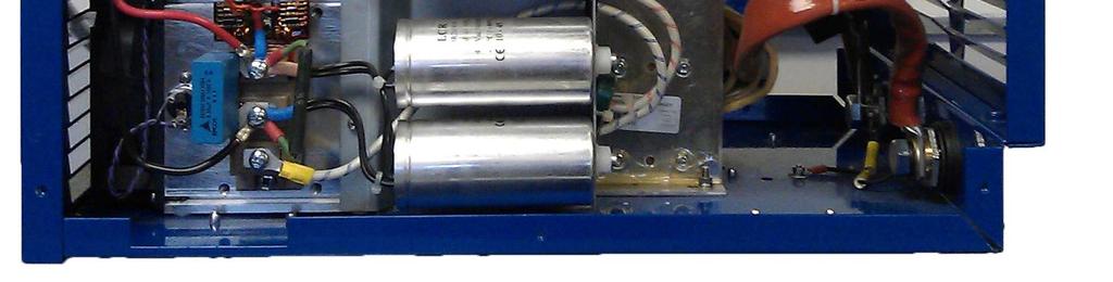
12 SECTION 7 PARTS BREAKDOWN Component Locations
13 SECTION 7 PARTS BREAKDOWN Parts List Item no. Description Part No. 3 1 Bridge handle (x 2) M0 2 On/Off switch M70069A 3 20mm diameter knob M00033A 4 Remote socket assembly M /90 panel mount Dix socket (x 2) M Mains Switch 3 phase power M Filter Diac assembly (x 3) M Auxiliary transformer M Fuse holder Fuse 3.15A slow blow, 32 x 6.3mm ceramic body M01088/89 M00020A 10 Soft start relay M Diode bridge M Fuse holder M00273 Fuse 6.3A slow blow, 20 x 5mm glass body M Soft start resistor assembly M Control PCB M Display PCB M Current transformer M IGBT (x 2) R4000 R5000 M60245 M IGBT Gate PCB (x 2) M Current transducer M Snubber Capacitors (x 2) M Power Resistors M Capacitor Assembly M Diode module (x 4) M Main inductor M Cooling fan (x 2) M Main transformer R4000 R5000 M01093 M De-coupling capacitor M90818 When ordering spare components please quote the serial number of the unit for which the parts are intended.
14
15
191 295 0077 Website: www.newarc.co.")
16 Head Office 6 Wincomblee Road Walker Riverside Newcastle upon Tyne NE6 3PF Aberdeen Office Unit 23 Kirkhill Place Kirkhill Industrial Estate, Dyce Aberdeen AB21 0GU Tel: +44 (0) Fax: +44 (0) Website: sales@newarc.co.uk Tel: +44 (0) Fax: +44 (0) Guarantee New-Arc Equipment Ltd warrants that its goods and services are guaranteed to meet the specific performance under the stated conditions of use. New-Arc cannot be held responsible for general wear and tear or for failure occurring due to misuse or abuse arising out of circumstances outside the stated conditions of use. The stated conditions of use are that considered normal industrial practice and are not exhaustive. Each machine is identified with a unique serial number and accompanied with the guarantee. New-Arc reserve the right to a) Repair. b)replace. c)authorise the reasonable cost of repair or replacement at an approved New-Arc service agent. d)credit for any purchased equipment (less reasonable depreciation for actual use and condition) at its entire discretion. This in no way affects your rights as a consumer. The guarantee is enclosed with each machine. Waiver Whilst every endeavour is made to ensure the details of this document are correct at the date of print. New-Arc accepts no liability for correctness in respect of any impending change in legislation or health and safety requirements. New-Arc also reserve the right to amend the detail of the document content without any notification to the consumer. If reference is made to New-Arc while utilising the document for spare parts purchase or instruction please advise the revision of the document to ensure correctness of information.
WFU12A-RV INSTRUCTION MANUAL. Important Information. Description. Processes. Wire Feed Unit
 Description Wire Feed Unit Processes Important Information All persons authorised to use, repair or service the wire feed unit, should read the section on safety, before any work is undertaken. Further
WFU12-4C. Newarc Ltd. UK s Leading Manufacturer Of Welding Equipment Newcastle +44 (0) Aberdeen +44 (0)
 Aberdeen +44 (0)") Description Wire Feed Unit Processes Important Information All persons authorised to use, repair or service the wire feed unit, should read the section on safety, before any work is undertaken. Further
Description Wire Feed Unit Processes Important Information All persons authorised to use, repair or service the wire feed unit, should read the section on safety, before any work is undertaken. Further
OPERATION INSTRUCTIONS
 www.r-techwelding.co.uk Email: sales@r-techwelding.co.uk Tel: 01452 733933 Fax: 01452 733939 ProArc 175 INVERTER ARC WELDER OPERATION INSTRUCTIONS Version 2017-10 2 3 Thank you for selecting the R-Tech
MMA 160S ARC/MMA WELDER OPERATION INSTRUCTIONS
 www.r-techwelding.co.uk MMA 160S ARC/MMA WELDER OPERATION INSTRUCTIONS 2 Thank you for selecting the R-Tech MMA160S Inverter Arc Welder. The MMA160S has many benefits over traditional Arc welders, including
WELDING INVERTER. PEGAS 160 E Smart PEGAS 200 E Smart OPERATING MANUAL. ALFA IN a.s. PEGAS E Smart Manual EN 04
 WELDING INVERTER PEGAS 160 E Smart PEGAS 200 E Smart OPERATING MANUAL PEGAS 160-200 E Smart Manual EN 04 2/12 CONTENT: 1. INTRODUCTION... 3 2. SAFETY INSTRUCTIONS AND WARNINGS... 4 3. TECHNICAL DATA...
OPERATION INSTRUCTIONS
 www.r-techwelding.co.uk Tel: 01452 733933 Fax 01452 733939 PLASMA 50HF INVERTER PLASMA CUTTER OPERATION INSTRUCTIONS Version 2014-1 2 Thank you for selecting the R-Tech PLASMA 50HF Inverter Plasma Cutter
DIGI-CUT 40PFC MV. Part No. 9030H OPERATOR S MANUAL
 DIGI-CUT 40PFC MV Part No. 9030H OPERATOR S MANUAL IMPORTANT Read this Owner s Manual completely before attempting to use this equipment. Save this manual and keep it handy for quick reference. Pay particular
OPERATION INSTRUCTIONS
 PLASMA 30DV DUAL VOLTAGE INVERTER PLASMA CUTTER OPERATION INSTRUCTIONS 2 Thank you for selecting the R-Tech Plasma 30DV Inverter Plasma Cutter 3 The Plasma 30DV has many benefits over traditional transformer
GSL Electronics Modified Sine Wave Power Inverters
 GSL Electronics Modified Sine Wave Power Inverters Congratulations on choosing one of our Modified Sine Wave Inverters for your application. There are 6 models in the range, which will meet most of your
OPERATION INSTRUCTIONS
 www.r-techwelding.co.uk email: sales@r-techwelding.co.uk Tel: 01452 733933 Fax 01452 733939 TIG160PDC DC TIG WELDER OPERATION INSTRUCTIONS Version 2014-1 2 Thank you for selecting the R-Tech Tig160PDC
QUATRO 450 OPERATOR S MANUAL
 QUATRO 450 OPERATOR S MANUAL IMPORTANT DO NOT INSTALL, OPERATE OR REPAIR THIS EQUIPMENT WITHOUT READING THIS MANUAL AND THE SAFETY SECTION CONTAINED INSIDE THIS MANUAL STARWELD WELDING SOLUTIONS WEBSITE:
OPERATION INSTRUCTIONS
 TIG200PDC TIG WELDER OPERATION INSTRUCTIONS 2 3 Thank you for selecting the R-Tech Tig200PDC Inverter DC Tig Welder. The Tig200PDC has many benefits over traditional tig welders, including pulse welding,
OWNER S OPERATING MANUAL
 OWNER S OPERATING MANUAL ARC 140 AMP WELDER TABLE OF CONTENTS Page Safety instructions 3-4 Inverter Arc Welder 5 Welder Information 5 Arc 140 AMP welder set up 6 Assembly instructions 6 Operation 7 Welding
OPERATION MANUAL M185. MIG/flux wire feeder welder. Serial Number: Where Purchase: Date of purchased:
 OPERATION MANUAL M185 MIG/flux wire feeder welder Serial Number: Where Purchase: Date of purchased: CONTENT 1. Safety... 2 2. Electrical principle drawing... 4 3. Specifications... 5 4. Front and rear
OPERATING INSTRUCTIONS
 www.r-techwelding.co.uk email: sales@r-techwelding.co.uk Tel: 01452 733933 Fax 01452 733939 IMIG 180 PORTABLE INVERTER MIG/MAG/MMA WELDER OPERATING INSTRUCTIONS Version 2017-1 Thank you for selecting
MULTIVOLTAGE PORTABLE BATTERY CHARGER MVM
 _ M MULTIVOLTAGE PORTABLE BATTERY CHARGER MVM User's MANUAL Code: MVM Version: 01-BF Date: OCT 2005 Page 1/10 _ 1. INTRODUCTION Before starting to use your Energic plus MVM battery charger, please take
Contents. Overview. Safety Instructions. Before Installation. Installation. Operation. Maintenance. Replacement Parts. System Specifications 8 01
 PrintPRO Universal Contents Overview 1 01 02 03 Overview of your extraction system (front) Overview of your extraction system (back) Overview of the Control Panel Safety Instructions 2 01 Important safety
FEATURES. Power Status and Charge Indicator: A red LED indicates the battery is charging and a green LED indicates the battery is fully charged.
 7-in-1 Power Station Model: 52036 DO NOT RETURN TO STORE. Please CALL 800-348-5004 for parts and service. CALIFORNIA PROPOSITION 65 WARNING: You can create dust when you cut, sand, drill or grind materials
INVERTER AIR PLASMA CUTTING MACHINE
 INVERTER AIR PLASMA CUTTING MACHINE OPERATION MANUAL DO NOT INSTALL, OPERATE OR MAINTAIN THIS MACHINE WITHOUT READING THIS MANUAL AND PLEASE ALWAYS THINK BEFORE YOU ACT. www.hyundaiwelding.com TECHNICAL
Table of Contents Foreword I. Product Introduction II. Notice For Safety III. Main Technical Parameters IV.
 Foreword Thank you for choosing the LGK-ID IGBT Digital Air Plasma Cutter of Delixi (Hangzhou) Inverter Co., Ltd. Before use LGK-ID IGBT Digital Air Plasma Cutter, please carefully read this Manual to
99 Washington Street Melrose, MA Fax TestEquipmentDepot.com. Instruction Manual. Model 1672 Triple Output Power Supply
 99 Washington Street Melrose, MA 02176 Fax 781-665-0780 TestEquipmentDepot.com Instruction Manual Model 1672 Triple Output Power Supply Contents Section Description Page No. CONTENTS 1 1 TEST INSTRUMENT
MP V 8A Electronic Smart Charger. Instruction and Information Manual
 MP7428 12V 8A Electronic Smart Charger Instruction and Information Manual In order to ensure correct and safe usage of your battery charger, you should read these instructions carefully. Please retain
SIP Direct Drive Oil-Lube Air Compressors - Operating & Maintenance Instructions
 SIP Direct Drive Oil-Lube Air Compressors - Operating & Maintenance Instructions Please read and fully understand the instructions in this manual before operation. Keep this manual safe for future reference.
Wilkins Safety Group
 H & S Guidance - Electricity INTRODUCTION Each year there are almost 1000 reportable accidents at work due to contact with electricity including a significant number of fatalities (about 20 a year). Even
POWER PINNER CD HAND WELDER 7300 OPERATOR S MANUAL
 POWER PINNER CD HAND WELDER 7300 OPERATOR S MANUAL Copyright: April 7, 2014 Gripnail Corporation Revised: January 25, 2018 An Employee Owned Company 97 Dexter Road East Providence, Rhode Island 02914-2045
O W N E R ' S M A N U A L
 1500 Watt DC to AC Power Inverter C o n v e r t s 1 2 V D C B a t t e r y P o w e r t o 1 1 0 V A C H o m e P o w e r O W N E R ' S M A N U A L SAVE THESE INSTRUCTIONS The recommended source of power is
1200W INVERTER GENERATOR
 1200W INVERTER GENERATOR MODEL NO: IG1200 PART NO: 8877070 OPERATION & MAINTENANCE INSTRUCTIONS LS0117 INTRODUCTION Thank you for purchasing this CLARKE 1200W Inverter Generator. Before attempting to use
PI1500X Power Inverter User s Manual
 PI1500X Power Inverter User s Manual featuring WARNING Failure to follow instructions may cause damage or explosion, always shield eyes. Read entire instruction manual before use. Warning: This product
instructions for roadstart units
 instructions for roadstart units model no: RS1.V5, RS102.V4, RS103.V3 Thank you for purchasing a Sealey product. Manufactured to a high standard, this product will, if used according to these instructions,
Operating Instructions. International English. CCS Dust Extractor
 Operating Instructions International English CCS Dust Extractor Electric Cast Saw Dust Removal System Warnings & Safety Rules WARNING!: THIS EQUIPMENT MUST BE EARTHED! Danger!: Possible explosion hazard
5 IN 1 JUMP START OPERATION & MAINTENANCE INSTRUCTIONS MODEL NO: JS5IN1 PART NO: LS0810
 5 IN 1 JUMP START MODEL NO: JS5IN1 PART NO: 6240005 OPERATION & MAINTENANCE INSTRUCTIONS LS0810 INTRODUCTION Thank you for purchasing this CLARKE product. Before attempting to use this product, please
X100P Load Bank. Read all instructions before using the load bank. Contents
 X100P Load Bank Read all instructions before using the load bank Contents 1. Components... 3 Total Assembly... 3 2) Specifications... 4 a) X100P Load Bank... 4 3) Receiving... 4 4) Safety... 5 a) Grounding...
BATTERY CHARGER-STARTER
 BATTERY CHARGER-STARTER MODEL NO: WBC240 & WBC400 PART NO: 6261505 & 6261515 OPERATION & MAINTENANCE INSTRUCTIONS GC0116 INTRODUCTION Thank you for purchasing this CLARKE Battery Charger/Starter. Please
GP-1000 Inverter. Go Power! Electric Inc. PO Box 6033 Victoria, BC V8P 5L4 Tel: Fax:
 Go Power! Manual GP-1000 Inverter Go Power! Electric Inc. PO Box 6033 Victoria, BC V8P 5L4 Tel: 866-247-6527 Fax: 866-607-6527 Email: info@gpelectric.com Table of Contents 1. INTRODUCTION 3 2. SPECIFICATIONS
Pro Booster 802Li. Please read and fully understand the instructions in this manual before operation. Keep this manual safe for future reference.
 Please dispose of packaging for the product in a responsible manner. It is suitable for recycling. Help to protect the environment, take the packaging to the local amenity tip and place into the appropriate
LESTRONIC II BATTERY CHARGER BUILT-IN OR PORTABLE CHARGERS
 LESTRONIC II BATTERY CHARGER BUILT-IN OR PORTABLE CHARGERS PLEASE SAVE THESE IMPORTANT SAFETY AND OPERATING INSTRUCTIONS For correct operation of the equipment, it is important to read and be familiar
POWER MTS210D MIG - TIG - MMA WELDING MACHINE OPERATION INSTRUCTIONS
 www.r-techwelding.co.uk email: sales@r-techwelding.co.uk Tel: 01452 733933 Fax 01452 733939 POWER MTS210D MIG - TIG - MMA WELDING MACHINE OPERATION INSTRUCTIONS Version 2014-1 2 Thank you for selecting
MODEL A96 SERIES. 130Vdc Switchmode Utility Rectifier / Battery Charger. Used with LaMarche Power Cage ECN/DATE
 MODEL A96 SERIES 130Vdc Switchmode Utility Rectifier / Battery Charger Used with LaMarche Power Cage CPN112138 ECN/DATE ISSUE DATE: ECN 17010-12/05 106 BRADROCK DRIVE DES PLAINES, IL. 60018-1967 (847)
LESTRONIC II BATTERY CHARGER MODEL 07210
 LESTRONIC II BATTERY CHARGER MODEL 07210 PLEASE SAVE THESE IMPORTANT SAFETY AND OPERATING INSTRUCTIONS For correct operation of the equipment, it is important to read and be familiar with this entire manual
MIG Welder T126, T136 & T166
 Please dispose of packaging for the product in a responsible manner. It is suitable for recycling. Help to protect the environment, take the packaging to the local amenity tip and place into the appropriate
ARC 1850 LIST OF FIGURES
 PAGE 1.0 INTRODUCTION... 1 2.0 WARRANTY... 1 3.0 UNPACKING YOUR UNIT... 1 4.0 SUGGESTED SAFETY PRECAUTIONS...... 1 4.1 PERSONAL SAFETY PRECAUTIONS. 1 4.2 POWER SUPPLY SAFETY PRECAUTIONS.. 2 5.0 GENERAL
VT Oil-Free Range Operators Handbook
 VT Oil-Free Range Operators Handbook Covering Models:- VT7 / VT7D VT10 / VT10D VT200 / VT200D VT300 / VT300D VT00 / VT00D BAMBI AIR COMPRESSORS LTD 12 Thimble Mill Lane Heartlands Birmingham B7 HT Tel:
XS400 Load Bank. Read all instructions before using the load bank. Contents
 Read all instructions before using the load bank Contents 1) Components... 3 Total Assembly... 3 2) Specifications... 4 3) Receiving... 4 4) Safety... 5 a) Grounding cam... 6 b) Power connections... 6
MASTERsine Inverter PXA Series Installation Guide
 Backup Power System Expert TM MASTERsine Inverter PXA Series Installation Guide Important Safety Instructions IMPORTANT: Read and save this Installation Guide for future reference. This chapter contains
Installation and Operation Guide. Tundra HD 2500 Power Inverter. for the. Webasto BlueCool Truck System
 Installation and Operation Guide Tundra HD 2500 Power Inverter for the Webasto BlueCool Truck System www.tundrainternational.com www.techwebasto.com BCTSP0063A Table of Contents 1. Introduction 4 1.1 Disclaimer.................................................................................
OWNER S OPERATING MANUAL
 OWNER S OPERATING MANUAL WELD AND CUT ARC/TIG INVERTER PLASMA 30 PLASMA CUTTER TABLE OF CONTENTS Safety instructions 3-4 Weld & Cut ARC/TIG and Plasma Cutter 5 Page Installation 6 Welder Information 6-8
JM-160C,JM-175C, JM-180C, JM-200C
 wilkinsonstar.com MIG Series MIG/MAG/MMA Compact welding machines Order code! JM-160C,JM-175C, JM-180C, JM-200C OPERATOR MANUAL Your new product Thank you for selecting this Jasic Technology, Wilkinson
1100W PORTABLE GENERATOR
 1100W PORTABLE GENERATOR MODEL NO: G1200 PART NO: 8010110 OPERATION & MAINTENANCE INSTRUCTIONS LS0312 INTRODUCTION Thank you for purchasing this CLARKE 1100W Portable Generator. Before attempting to use
OPERATION MANUAL MODELS TWE-250 TWE-321 TWE-375 TRU WELD EQUIPMENT COMPANY 6400 N. HONEYTOWN ROAD SMITHVILLE, OHIO (330)
") OPERATION MANUAL MODELS TWE-250 TWE-321 TWE-375 TRU WELD EQUIPMENT COMPANY 6400 N. HONEYTOWN ROAD SMITHVILLE, OHIO 44677 (330) 669 2773 CONTENTS Section Description Pages 1 Introduction 3 2 External Features
OPERATION MANUAL MODELS TWE-250 TWE-321 TWE-375 TRU WELD EQUIPMENT COMPANY 6400 N. HONEYTOWN ROAD SMITHVILLE, OHIO 44677 (330) 669 2773 CONTENTS Section Description Pages 1 Introduction 3 2 External Features
Chargestar P24 / P32 Battery Charger Startmaster P300 Starter / Charger
 Please dispose of packaging for the product in a responsible manner. It is suitable for recycling. Help to protect the environment, take the packaging to the local amenity tip and place into the appropriate
Car Battery Charger Instructions for Use
 BATTERY CHARGER 12Volt 4Amp FOR INDOOR USE ONLY Power Details: Input: 230-240Vac; 50Hz; 52W Output: 12V DC; 2.8A Maximum Charge Rate: 4A RMS Read these instructions before operating this car battery charger
PC40 INVERTER PLASMA CUTTER 230V 40A SUM OWNER S MANUAL
 PC40 INVERTER PLASMA CUTTER 230V 40A SUM-900990 OWNER S MANUAL WARNING: Read carefully and understand all ASSEMBLY AND OPERATION INSTRUCTIONS before operating. Failure to follow the safety rules and other
Operations and Service Manual. XE400D-SB Load Bank
 Operations and Service Manual XE400D-SB Load Bank Read all instructions before using the load bank Contents 1. Components... 3 Total Assembly... 3 2) Specifications... 4 a) XE400D-SB Load Bank... 4 3)
Operations and Service Manual. X30208 Load Bank
 Operations and Service Manual Read all instructions before using the load bank Contents 1. Components... 3 Total Assembly... 3 2) Specifications... 4 a)... 4 3) Receiving... 5 4) Safety... 5 a) Ground
Warning: Electricity. Wear Protective Gloves
 instructions for roadstart emergency jump starter 12/24V 3200/1600 peak amps model no: RS105.V4 Thank you for purchasing a Sealey product. Manufactured to a high standard, this product will, if used according
Caddy. Tig 2200i AC/DC. Instruction manual GB Valid for: serial no. 711-, 747-xxx-xxxx
 Caddy Tig 2200i AC/DC Instruction manual 0460 225 301 GB 20180920 Valid for: serial no. 711-, 747-xxx-xxxx TABLE OF CONTENTS 1 SAFETY... 4 1.1 Meaning of symbols... 4 1.2 Safety precautions... 4 2 INTRODUCTION...
MODUL-CONNECT 1.2. Owner s Manual. Modular, digital wiring and control system. Document Part Number MSMC Rev 9 (04/18)
") MODUL-CONNECT 1.2 Modular, digital wiring and control system Owner s Manual Document Part Number MSMC Rev 9 (04/18) Service Contact Information E-mail: info@modul-system.com Phone: +46 31 746 87 00 Web:
MODUL-CONNECT 1.2 Modular, digital wiring and control system Owner s Manual Document Part Number MSMC Rev 9 (04/18) Service Contact Information E-mail: info@modul-system.com Phone: +46 31 746 87 00 Web:
MMW220PC OWNER S MANUAL
 MMW220PC OWNER S MANUAL 12/2015 WARNING: Read carefully and understand all ASSEMBLY AND OPERATION INSTRUCTIONS before operating. Failure to follow the safety rules and other basic safety precautions may
MMWP125I OWNER S MANUAL
 MMWP125I OWNER S MANUAL 1/2017 WARNING: Read carefully and understand all ASSEMBLY AND OPERATION INSTRUCTIONS before operating. Failure to follow the safety rules and other basic safety precautions may
OPERATING AND MAINTENANCE MANUAL. Primary Current Injection Test Set. 750ADM-H mk2
 OPERATING AND MAINTENANCE MANUAL Product: Type: Primary Current Injection Test Set 750ADM mk2 750ADM-H mk2 DESIGNED AND MANUFACTURED BY: T & R Test Equipment Limited 15-16 Woodbridge Meadows, Guildford,
Nature Power Inverters. True Sinewave Inverter Modified Sinewave Inverter. Owner s Manual
 Version 1.1 Version 2 Nature Power Inverters True Sinewave Inverter Modified Sinewave Inverter Owner s Manual!!!!!!!!!!! 38304 38204 For safe and optimum performance, the Power Inverter must be used properly.
Compact Sine Inverter
 Compact Sine Inverter Instructions for installation & use Applies to the following models: Output power: 700watt, 1000 watt, 1500watt, 2000 watt & 3000 watts Output voltage: and output, 50Hz & 60Hz Output
Quick Draw Spool Gun OWNER S MANUAL
 Quick Draw Spool Gun OWNER S MANUAL WARNING: Read carefully and understand all ASSEMBLY AND OPERATION INSTRUCTIONS before operating. Failure to follow the safety rules and other basic safety precautions
Battery Chargers Sealed or Valve Regulated Lead Acid Batteries Models: PSC A AND PSC A
 Battery Chargers Sealed or Valve Regulated Lead Acid Batteries Models: PSC-122000A AND PSC-241000A Operating Instructions WARNING CONCERNING THE REMOVAL OF COVER: CAUTION: TO PREVENT THE RISK OF ELECTRIC
CX-SERIES ADVANCED BATTERY CHARGER
 CX-SERIES ADVANCED BATTERY CHARGER Table of Content 1. IMPORTANT SAFETY INFORMATION... 2 1-1 General Safety Precautions... 2 1-2 Battery Precautions... 2 2. FEATURES... 3 2-1 Battery Charging Curve...
OWNER S OPERATING MANUAL
 OWNER S OPERATING MANUAL MIG 100 GASLESS WELDER TABLE OF CONTENTS Page Safety instructions 3-4 MIG Welders 5 Welder Information 5 Gasless welder set up 6 Operation 6-10 Troubleshooting Guide 11-12 Spare
Rescue Pac. Please read and fully understand the instructions in this manual before operation. Keep this manual safe for future reference
 Please dispose of Packaging for the product in a responsible manner. It is suitable for recycling. Help to protect the environment, take the packaging to the local amenity tip and place into the appropriate
OPERATION/ MAINTENANCE MANUAL
 208 VERSION OPERATION/ MAINTENANCE MANUAL TABLE OF CONTENTS Section 1 SAFETY PRECAUTIONS PAGE 1.0 INTRODUCTION... 1 2.0 WARRANTY... 1 3.0 UNPACKING YOUR UNIT... 1 4.0 SUGGESTED SAFETY PRECAUTIONS... 1
DC TO AC POWER INVERTER
 DC TO AC POWER INVERTER 12V / 24V / 48Vdc Input 115V / 230Vac Output 150W ~ 6000W Output cont. L-Series User Manual Before install and use your Inverter, read the User Manual and safety instructions. Cooler
User manual. B950I, B1000i, B2000i, B3000i
 User manual B950I, B1000i, B2000i, B3000i Always read the user manual thoroughly before using the generator. Never use the generator in a closed room/area. Exhaust may cause suffocation. The exhaust pipe
Operator Manual For use with WFCO ULTRA III Deckmount Converter WF-9800 Series (model number located on the cover of the unit)
") Operator Manual For use with WFCO ULTRA III Deckmount Converter WF-9800 Series (model number located on the cover of the unit) Distributed in the U.S.A. and Canada by ARTERRA DISTRIBUTION Warranty Service
Operator Manual For use with WFCO ULTRA III Deckmount Converter WF-9800 Series (model number located on the cover of the unit) Distributed in the U.S.A. and Canada by ARTERRA DISTRIBUTION Warranty Service
Installation Instructions for Load Management Kit A051C329
 Instruction Sheet 12-2014 Installation Instructions for Load Management Kit A051C329 1 Introduction The information contained within is based on information available at the time of going to print. In
OPERATION MANUAL MODELS TWE-250 TWE-321 TWE-375 TRU WELD EQUIPMENT COMPANY 6400 N. HONEYTOWN ROAD SMITHVILLE, OHIO (330)
") OPERATION MANUAL MODELS TWE-250 TWE-321 TWE-375 TRU WELD EQUIPMENT COMPANY 6400 N. HONEYTOWN ROAD SMITHVILLE, OHIO 44677 (330) 669 2773 Version 1.3 Date 10/20/2010 TRU WELD EQUIPMENT LIMITED WARRANTY All
OPERATION MANUAL MODELS TWE-250 TWE-321 TWE-375 TRU WELD EQUIPMENT COMPANY 6400 N. HONEYTOWN ROAD SMITHVILLE, OHIO 44677 (330) 669 2773 Version 1.3 Date 10/20/2010 TRU WELD EQUIPMENT LIMITED WARRANTY All
MODEL Nos: CVAC20SS CVAC25SS CVAC30SSR OPERATING & MAINTENANCE INSTRUCTIONS. Distributed by CLARKE International Ltd.
 MODEL Nos: CVAC20SS CVAC25SS CVAC30SSR OPERATING & MAINTENANCE INSTRUCTIONS Distributed by CLARKE International Ltd. 1006 Thank you for selecting this VAC KING Stainless Steel Vacuum Cleaner, which will
MPPC40DVI OWNER S MANUAL
 MPPC40DVI OWNER S MANUAL 4/2017 WARNING: Read carefully and understand all ASSEMBLY AND OPERATION INSTRUCTIONS before operating. Failure to follow the safety rules and other basic safety precautions may
LESTRONIC II BATTERY CHARGER MODEL 19740
 *01679* LESTRONIC II BATTERY CHARGER MODEL 19740 PLEASE SAVE THESE IMPORTANT SAFETY AND OPERATING INSTRUCTIONS For correct operation of the equipment, it is important to read and be familiar with this
GUIDE TO MAINTENANCE PRACTICES FOR DISTRIBUTION NETWORKS IN THE DISTRIBUTION SECTOR OF THE NAMIBIAN ELECTRICITY SUPPLY INDUSTRY
 PART B-04 TITLE: DISTRIBUTION SUBSTATIONS SPECIFICATION NO: B-04 INCEPTION DATE: AFTER GAZETTING (WORKING DOCUMENT FOR A 2 YEAR PERIOD) AMENDMENTS/REVISIONS DATE PAGE PARAGRAPH DESCRIPTION ORIGINATOR APPROVED
Switching DC Power Supply
 99 Washington Street Melrose, MA 02176 Phone 781-665-1400 Toll Free 1-800-517-8431 Visit us at www.testequipmentdepot.com Model 1693, 1694 Switching DC Power Supply INSTRUCTION MANUAL 1 Safety Summary
KV4-300 mk2. KV5-200 mk2. KV5-100T mk2. KV3-250 mk2
 OPERATING AND MAINTENANCE MANUAL Product: Type: High Voltage AC Test Set KV3-250 mk2 KV4-300 mk2 KV5-100 mk2 KV5-100T mk2 KV5-200 mk2 DESIGNED AND MANUFACTURED BY: T & R Test Equipment Limited 15-16 Woodbridge
Installation Instructions for Aux 101 Kit A044Z055
 Instruction Sheet 7-2013 Installation Instructions for Aux 101 Kit A044Z055 1 Introduction The information contained within is based on information available at the time of going to print. In line with
DC Master 24/ A
 USERS MANUAL DC Master 24/12 50-60A DC-DC converter MASTERVOLT Snijdersbergweg 93, 1105 AN Amsterdam The Netherlands Tel.: +31-20-3422100 Fax.: +31-20-6971006 www.mastervolt.com ENGLISH Copyright 2015
Battery Chargers Sealed or Valve Regulated Lead Acid Batteries Model: PSC A
 Battery Chargers Sealed or Valve Regulated Lead Acid Batteries Model: PSC-124000A OPERATING PROCEDURES AND SAFETY INSTRUCTIONS CAUTION: TO PREVENT THE RISK OF ELECTRIC SHOCK, DO NOT REMOVE COVER NO USER
OWNER'S MANUAL WARNING DANGER. Propane cylinders sold separately. The propane cylinder must be disconnected when this firebowl is not use.
 OWNER'S MANUAL READ BEFORE USE! Model No.: BH5003-3 Style No.: 66646 For Outdoor Use Only! Use Propane Gas Only! Propane cylinders sold separately. USE PROPANE GAS ONLY! -Do not store or use gasoline or
OPERATOR S MANUAL. TW-i SERIES. Capacitor Discharge Stud Welder. MODELS: TW-i 250 TW-i 250CP TW-i 321 TW-i 375
 OPERATOR S MANUAL TW-i SERIES Capacitor Discharge Stud Welder MODELS: TW-i 250 TW-i 250CP TW-i 321 TW-i 375 TRU-WELD EQUIPMENT COMPANY www.truweldstudwelding.com (330) 725-7744 CONTENTS Description Pages
30 Amp Solar Charge Controller
 V1.4-M 25Aug2017 30 Amp Solar Charge Controller Owner s Manual WARNING: Read carefully and understand all ASSEMBLY AND OPERATION INSTRUCTIONS before operating. Failure to follow the safety rules and other
Abbeon Cal, Inc. Model BD-50E HIGH FREQUENCY GENERATOR OPERATING MANUAL
 Abbeon Cal, Inc. Model BD-50E HIGH FREQUENCY GENERATOR OPERATING MANUAL DESCRIPTION. The Model BD-50E is a rugged tester designed for testing tank lining and other applications where extended use is necessary.
Time Electronics DC Voltage Calibrator. Technical Manual
 Time Electronics 1010 DC Voltage Calibrator Technical Manual V1.1 20/04/09 Time Electronics Ltd Botany Industrial Estate, Tonbridge, Kent, TN9 1RH Tel: +44(0)1732 355993 Fax: +44(0)1732 770312 Email: mail@timeelectronics.co.uk
12v / 24v Diesel Transfer Pump Kit
 Please dispose of packaging for the product in a responsible manner. It is suitable for recycling. Help to protect the environment, take the packaging to the local amenity tip and place into the appropriate
TECHNICAL MANUAL. Inverter / Charger Combi. Combi SW 12V 1600VA Réf : PF Combi SW 24V 3800VA Réf : PF NOT_COMBI_SW-00
 TECHNICAL MANUAL EN Inverter / Charger Combi Combi SW 12V 1600VA Réf : PF.16088 Combi SW 24V 3800VA Réf : PF.16089 SAFETY PRECAUTIONS TO PREVENT ANY RISK OF ELECTRIC SHOCK OR FIRE, READ THIS MANUAL CAREFULLY
Go Power! Manual. GP-1750HD Inverter GP-2500 Inverter
 Go Power! Manual GP-1750HD Inverter GP-2500 Inverter Go Power! Electric Inc. PO Box 6033 Victoria, BC V8P 5L4 Tel: 866-247-6527 Fax: 866-607-6527 Email: info@gpelectric.com Table of Contents 1. INTRODUCTION...
04979, 04980, 04981, 04982, 04983, 04984, 39054, 39055, 39056, 39057, 39225, 81459,
 Hydraulic Bottle Jacks 04979, 04980, 04981, 04982, 04983, 04984, 39054, 39055, 39056, 39057, 39225, 81459, 82132. These instructions accompanying the product are the original instructions. This document
Pure Sine Wave Inverter 600W-24V User Manual
 Pure Sine Wave Inverter 600W-24V User Manual Manual Version:INV-600W-2016-1 Table of Contents 1. INTRODUCTION... 1 1.1 General Description... 1 1.2 Key Features... 2 2. SAFETY INSTRUCTIONS... 2 2.1 Installation
TABLE OF CONTENTS. 300 W Mobile Power Outlet SAVE THESE INSTRUCTIONS!
 300 W Mobile Power Outlet 011-1870-6 TECHNICAL SPECIFICATIONS... 3 Safety Information... 4 KEY PARTS diagram... 7 INTENDED USE... 9 Options for connecting devices to the power inverter... 9 Operation...
1. GENERAL SAFETY INSTRUCTIONS 2. GENERAL SAFETY RULES GENERAL OBSERVATIONS.
 ENGLISH IMPORTANT: The manual you are reading contains fundamental information regarding the safety measures to be adopted when installing and starting up. It is therefore of utmost importance that both
DC to AC Power Inverters
 Manufacturer of Dimensions TM Inverters 4467 White Bear Parkway St. Paul, MN 55110 Phone: 651-653-7000 Fax: 651-653-7600 E-mail: inverterinfo@sensata.com Web: www.dimensions.sensata.com ISO 9001:2000 Certified
DC to AC Power Inverters
 Manufacturer of Dimensions TM Inverters 4467 White Bear Parkway St. Paul, MN 55110 Phone: 651-653-7000 Fax: 651-653-7600 E-mail: inverterinfo@sensata.com Web: www.dimensions.sensata.com 121114C OWNERS
Model: PI-140 Power Inverter Converts 12V DC battery power to 120V AC household power
 OWNER S MANUAL Model: PI-140 Power Inverter Converts 12V DC battery power to 120V AC household power READ THE ENTIRE MANUAL BEFORE USING THIS PRODUCT. FAILURE TO DO SO COULD RESULT IN SERIOUS INJURY OR
KING CANADA 950W PORTABLE GENERATOR MODEL: KCG-951G INSTRUCTION MANUAL COPYRIGHT 2011 ALL RIGHTS RESERVED BY KING CANADA TOOLS INC.
 KING CANADA 950W PORTABLE GENERATOR MODEL: KCG-951G INSTRUCTION MANUAL COPYRIGHT 2011 ALL RIGHTS RESERVED BY KING CANADA TOOLS INC. WARRANTY & SERVICE INFORMATION 1-YEAR LIMITED WARRANTY FOR THIS 950W
MPPC60I OWNER S MANUAL
 MPPC60I OWNER S MANUAL 4/2017 WARNING: Read carefully and understand all ASSEMBLY AND OPERATION INSTRUCTIONS before operating. Failure to follow the safety rules and other basic safety precautions may
Tel: Fax MTS255S
 www.r-techwelding.co.uk email: sales@r-techwelding.co.uk Tel: 01452 733933 Fax 01452 733939 MTS255S MIG-TIG-MMA WELDING MACHINE OPERATION INSTRUCTIONS Version 2017-10 - 2 - Thank you for selecting the