TRANSPORTABILITY GUIDANCE COMMERCIAL UTILITY CARGO VEHICLE (CUCV)
|
|
|
- Joshua Milo Neal
- 5 years ago
- Views:
Transcription
1 TM TECHNICAL MANUAL TRANSPORTABILITY GUIDANCE COMMERCIAL UTILITY CARGO VEHICLE (CUCV) H E A D Q U A R T E R S, D E P A R T M E N T O F T H E A R M Y 30 JANUARY 1987
2 30 January 1987 TM TECHNICAL MANUAL HEADQUARTERS DEPARTMENT OF THE ARMY WASHINGTON, DC, 30 January 1987 TECHNICAL MANUAL TRANSPORTABILITY GUIDANCE COMMERCIAL UTILITY CARGO VEHICLE (CUCV) CHAPTER SECTION I. II. CHAPTER 3. CHAPTER 4. SECTION I. II. III. CHAPTER 5. Section I. II. III. CHAPTER 6. SECTION I. II. INTRODUCTION Purpose and Scope Safety Definitions of Warnings, Cautions, and Notes Reporting of Recommendations and Comments TRANSPORTABILITY DATA GENERAL Scope Description CHARACTERISTICS AND RELATED DATA General Transportability Drawings Towing Capability Frame Reinforcement Tiedown of CUCVs Reduced Configration Unusual Characteristics Hazardous and Dangerous Characteristics SAFETY General Specific Safety Requirement AIR TRANSPORTABILITY GUIDANCE GENERAL Scope Maximum Utilization of Aircraft Safety Responsibility TRANSPORT BY US AIR FORCE AIRCRAFT Air Capabilities Typical Loads TRANSPORT BY US ARMY AIRCRAFT Fixed Wing Aircraft Rotary Wing Aircraft Civil Reserve Air Fleet (CRAF) HIGHWAY TRANSPORTABILITY GUIDANCE GENERAL Scope Safety SELF-PROPELLED MOVEMENT General TRANSPORT BY SEMITRAILER Transport by Semitrailer Preparation for Transport Loading on Semitrailer MARINE AND TERMINAL TRANSPORTABILITY GUIDANCE GENERAL Scope Safety LOADING AND SECURING General Rules for Stowage General Cargo and Barge-Type (LASH and SEABEE) Ships Paragraph Page
3 TM January 1987 CHAPTER 7. SECTION I. II. III. Roll-On/Roll-Off (RORO), Seatrain, and Attack Cargo Ships. Landing Craft and Amphibious Vehicles RAIL TRANSPORTABILITY GUIDANCE GENERAL Scope Maximum Utilization of Railcars Safety TRANSPORT ON CONUS RAILWAYS General Preparation for Loading Loading on Railcars with Wood Deck Floor Blocking and Tiedown on Railcar with Wood Floor Loading on Flatcars with Steel Decks and Center Tiedown Rails Tiedown on Railcars with Steel Decks and Center Tiedown Rails CUCV with S-250 Shelter Secured on Steel Deck Railcar Loading on BiLevel Railcars TRANSPORT ON FOREIGN RAILWAYS General Transport on Foreign Service Flatcars Paragraph Page
4 30 January 1987 TM LIST OF ILLUSTRATIONS Figure No. Title Page M1008/M1008Al, side and rear views M1009, side and rear views M1010, side and rear views M1028/M1028Al, side and rear views Front view of tow hooks on all CUCVs M1009, rear view of tow hooks and tow pintle Rear view of tow hooks and tow pintle on all other CUCVs Frame reinforcement bracket, front Cargo tiedowns in CUCV cargo beds Tiedown diagram of CUCV in C-130 aircraft Tiedown diagram of CUCV in C-141 aircraft Tiedown diagram of CUCV in C-5A aircraft Tiedown diagram of CUCV in CH47 helicopter Tiedown of CUCV on a semitrailer Blocking and tiedown details of CUCV on a semitrailer CUCV lifted by a four legged sling and spreader bar Typical blocking and tiedown of CUCV in hold of general cargo vessel Typical blocking and tiedown of CUCV in SEABEE barge Typical tiedown of CUCV in RORO vessel Blocking and tiedown of CUCV on flatcar with wood floor Blocking and tiedown details Blocking and tiedown of six S-250 shelters on flatcar with wood floor CUCV loaded on railcar with steel deck and center tiedown rails CUCV with S-250 shelter secured in steel deck railcar Front tiedown bracket Rear tiedown bracket Communication shelter dunnage contents Dunnage size and cutting dimensions Dunnage nailing and assembly instructions CUCV loaded on bilevel railcars Figure No. LIST OF TABLES Title Page Tiedown Data for CUCV in USAF C-130 Aircraft (Fig 4-1) Tiedown Data for CUCV in USAF C-141 Aircraft (Fig 4-2) Tiedown Data for CUCV in USAF C-5A Aircraft (Fig 4-3) Tiedown Data for the CUCV in US Army CH47 Helicopter (Fig 4-4) Bill of Materials for Tiedown of CUCV on a Semitrailer Application of Materials for Tiedown of CUCV on a Semitrailer Bill of Materials for Blocking and Tiedown of CUCV on a Semitrailer Application of Materials for Blocking and Tiedown of CUCV on a Flatbed Semitrailer (Fig 5-1 and 5-2) Bill of Materials for Blocking and Tiedown of CUCV in General Cargo or Barge Type Vessels (Fig 6-2) Application of Materials for Blocking and Tiedown of CUCV in General Cargo or Barge Type Vessels (Fig 6-2) Bill of Materials for Blocking and Tiedown of CUCV on Flatcar with Wood Floor (Fig 7-1) Application of Materials for Blocking and Tiedown of CUCV on General Purpose Flatcar (Fig 7-1) Bill of Materials for Blocking and Tiedown of Six S-250 Shelters on Flatcars with Wood Floor (Fig 7-3) Application of Materials for Blocking and Tiedown of Six S-250 Shelters on Flatcars with Wood Floor (Fig 7-3) Application of Chain Tiedowns for Securing CUCVs on Railcars with Steel Decks and Center Tiedown Rails (Fig 7-4) Materials used to Fabricate Auxiliary Shelter Cables Parts List for Front Tiedown Bracket Parts List for Rear Tiedown Bracket Application of Chain Tiedowns for Securing CUCVS on Bilevel Railcars (Fig 7-11) iii
5 30 January 1987 TM CHAPTER 1 INTRODUCTION 1-1. Purpose and Scope a. This manual provides transportability guidance for logistical handling and movement of the commercial utility cargo vehicles (CUCVs). b. This manual is intended for transportation officers and other personnel responsible for providing movement or for providing transportation services with appropriate information to ensure safe transport of the CUCVs. Included are significant technical and physical characteristics, as well as safety considerations required for worldwide movement by various transportation modes Safety Appropriate precautionary measures required during movement of the CUCVs are contained in chapter Definitions of Warnings, Cautions, and Notes Throughout this manual, warnings, cautions, and notes emphasize important or critical guidance. They are used for the following conditions: a. Warning. Instructions that, if not strictly followed, could result in injury to or death of personnel. b. Caution. Instructions that, if not strictly obresult in damage to or destruction of served, could equipment or material. c. Note. An operating procedure or condition that must be emphasized Reporting of Recommendations and Comments Individual users of this manual are encouraged to submit comments and recommended changes for its improvement. Comments and recommendations should be prepared on DA Form 2028 (Recommended Changes to LA Publications and Blank Forms) and forwarded to Commander, Military Traffic Management Command Transportation Engineering Agency, ATTN: MTT-TRV, PO BOX 6276, Newport News, VA Electrically transmitted messages should be addressed to CDR MTMCTEA FT EUSTIS VA//MTT-TRV//. A reply will be furnished by this command. 1-1
6 30 January 1987 TM CHAPTER 2 TRANSPORTABILITY DATA 2-1. scope Section 1. This chapter provides a general description of the commercial utility cargo vehicles (CUCVs). Included are identification photographs and tabulated transportability characteristics and data that are necessary in the movement of these vehicles Description The CUCV is a family of light commercial trucks modified for military use as tactical standard mobility light duty vehicles. The family of vehicles include the truck, tactical cargo; truck, tactical utility; truck, ambulance; and truck, tactical cargo shelter carrier. Each of these vehicles is powered by a 6.2-liter diesel engine, with an automatic transmission and four-wheel drive. The vehicles can transport utility items and general cargo/personnel. The CUCV family consists of the following vehicles: GENERAL a. M1008/M1008A1 Truck, Tactical Cargo, 5/4- Ton, 4x4. The tactical cargo truck can transport both cargo and troops. The M1008A1 model includes a communication rack so radios can be mounted in the cargo area. b. M1009 Truck, Tactical Utility, 3/4-Ton, 4x4. The tactical utility truck is a command and control vehicle that can transport four individuals (including operator), their equipment and weapons and the required communications equipment. c. M1010 Truck, Ambulance, 5/4-Ton, 4x4. The ambulance truck can transport eight ambulatory or four litter patients in the patient compartment plus the driver and one cab passenger. d. M1028/M1028A1 Truck, Tactical Cargo Shelter Carrier, 3,600-Pound, 4x4. This vehicle carries the S-250 communication shelter. The M1028A1 model includes a power takeoff on the transfer. Section Il. CHARACTERISTICS AND RELATED DATA 2-3. General numbers may affect the loadability of trucks as re- The following characteristics and data are applica- lated to guidance shown in this manual. ble to the model number shown. Changes in model a. M1008/M1008A1 Truck, Tactical Cargo, 5/4 Ton, 4x4. 2-1
7 TM January 1987 c. M1010 Truck, Ambulance, 5/4-Ton, 4x4. d. M1028/M1028A1 Truck, Tactical Cargo Shelter Carrier, 3,600-Pound, 4x Transportability Drawings Transportability drawings of the vehicles, with dimensions required for determining the loadability of the vehicles by various transport modes, are shown in figures 2-1 through
8 30 January 1987 TM Figure
9 TM January Figure 2-2.
10 30 January 1987 TM Figure
11 TM January
12 30 January 1987 TM Towing Capability Each CUCV has two multipurpose tow hooks (shackle and pin assemblies) on the front (figure 2-5), two located on the rear, and a tow pintle (figs 2-6 and 2-7) also on the rear. Each of the tow hooks can be used as a lifting or tiedown device. Table 2-1 gives the towing capacity of the tow pintle for the CUCVs. 2-7


13 TM January 1987 Figure 2-5. Front view of tow hooks on all CUCVs. 2-8
14 30 January 1987 TM MULTI-PURPOSE TOW HOOKS PINTLE Figure 2-6. M1009, rear view of tow hooks and tow pintle. 2-9
15 TM January 1987 MULTI-PURPOSE TOW HOOKS PINTLE CORNER MARKER/STOP BLACK LIGHT Figure 2-7. Rear view of tow hooks and tow pintle on all other CUCVs. 2-10
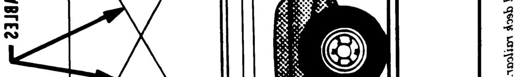
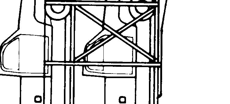
16 30 January 1987 TM Frame Reinforcement The M1008, M1008A1, M1010, M1028, and M1028A1 models of the CUCVs manufactured before March 1985 must have the frame reinforcement bracket applied (fig 2-8). Each vehicle must be checked to see if this bracket has been applied on all models before the CUCVs are lifted at their gross vehicle weight with a crane. 2-11
17 TM January 1987 Figure
18 30 January 1987 TM Tiedown of CUCVs The towing eyes located on the front and rear of the CUCVs are used as the tiedown points for the vehicles. In the cargo trucks, eight cargo tiedowns have been installed. Four are located on each side at about 4, 28,72, and 90 inches from the front face of the cargo compartment (fig 2-9). Table 2-1. Towing Capcity of Tow Pintles on CUCVs Definitions of Terms Used in Table: 1. Curb weight: The weight of base vehicle with BII and all fuels and lubes topped off. 2. Payload: The operator, passengers, personnel gear, cargo, trailer tongue load, or anything on the vehicle that increases the gross weight above the curb weight. 3. Gross vehicle weight rating (GVWR): The maximum gross weight at which the vehicle is permitted to be operated. 4. Gross towed load: The weight of the towed trailer and its payload. 5. Trailer tongue load: The vertical load placed on the trailer towing pintle by the trailer lunette. The lunette must be considered part of the truck payload and should not exceed 10 percent of the gross trailer load. 6. Flight-line towing allowance: Fixed and rotary wing aircraft which exceed the normal maximum gross towed load may be towed under limited operational procedures as follows: a. Speed will not exceed 5 mph. b. Vehicle will be operated with transmission in low range ( 1 ), c. The gross load (ie., the aircraft) will not exceed 15,000 lb. d. The tongue load will not exceed 100 lb. for the M1009 and M1028A1. e. Operation will be on flat (level) hard surface. transfer case in 2W drive. 300 lb. for M1008, M1008A1, M1028 or 2-13
19 TM January 1987 Figure 2-9. Cargo tiedowns in CUCV cargo beds. 2-14
20 30 January 1987 TM Reduced Configuration Economical transport can be obtained by reducing such vehicle to its minimum dimensions for transport. The vehicle s removable items such as bows and tarps should be stowed in the vehicle cargo compartment. Cargo will not cause vehicle to exceed the maximum certified weight when prepared for airlift Unusual Characteristics The vehicles have no unusual characteristics that require that special attention be given to temperature, atmospheric pressure, or humidity variations during exposure to normal transportation environments Hazardous and Dangerous Characteristics Unless the vehicles are shipped with ammunition or explosives under the provisions of the Department of Transportation Special Permit No (applicable only to shipment by motor vehicle or rail in periods of actual emergency), they will not present any hazardous or dangerous characteristics during normal transport. 2-15
21 30 January 1987 TM CHAPTER 3 SAFETY 3-1. General General safety considerations and precautions for handling and moving the CUCVs are as follows: a. The entire vehicle must be checked to ensure that all loose items are properly secured to prevent damage during shipment. b. A ground guide must be used when the vehicle is backed or moved in a confined area. c. Other operational safety precautions are outlined in the operators manual. WARNING Fire extinguishers must be able during all loading and erations. WARNING readily availunloading op- If the vehicle is operated during loading and unloading, proper ventilation must be provided. Prolonged inhalation of exhaust fumes could be fatal. WARNING Personnel must not stand or walk under the vehicle when the vehicle is being lifted. d. All lifts should have sufficient guidelines attached to control the swing of the vehicle. e. Slings and sling items used in loading and unloading operations should be inspected for safe working conditions. WARNING The CUCVs will not be externally lifted by helicopter. CAUTION The CUCVs, at maximum gross weight, cannot be lifted by cranes unless the frame modification kit has been applied. This modification is required on all models except the M1009 (fig 2-8). CAUTION When the CUCV with the S-250 shelter is shipped by rail, using wood deck railcars, the shelter must be removed and shipped separately to prevent damage to the shelter. When using steeldeck cushioned frame flatcars, the shelter may remain on the vehicle if secured as shown in figure 7-5. NOTE The CUCV with S-250 mounted must be loaded aboard C-130 and C-141 aircraft forward end first. Do not attempt to load by backing aboard Specific Safety Requirements Pertinent safety requirements by individual modes are provided, where applicable, in the subsequent chapters. 3-1
22 30 January 1987 TM CHAPTER 4 AIR TRANSPORTABILITY GUIDANCE 4-1. Scope Section I. GENERAL This chapter provides air transportability guidance for movement of the CUCVs. It covers technical and physical characteristics, as well as safety considerations, and prescribes the materials required to prepare, load, and unload vehicles on US Air Force aircraft. Also, it provides examples of tiedown diagrams and data tables for loading vehicles in C-130, C-141, and C-5A aircraft Maximum Utilization of Aircraft Cargo may be carried in the cargo compartment of the CUCV if the gross vehicle weight rating is not exceeded. Such cargo must be securely restrained in the vehicle, otherwise cargo must be removed from the vehicle and secured to the aircraft floor. The restraining device must meet the same restraint criteria as the vehicle whether the cargo is located in or out of the vehicle. The load must not exceed the maximum rated load capacity for these vehicles. The weight of the vehicle and its cargo must be accurate. The vehicle and its cargo are considered as one package, and the gross vehicle weight is used to determine tiedown requirements in accordance with chapter 4, FM 55-9 (Unit Air Movement Planning) Safety In addition to the safety precautions contained in chapter 3, the following should be noted. a. The activity offering the vehicle for air transport will notify the aircraft commander or his/her designated representative when ammunition or explosives are to be transported within the vehicles. b. In accordance with TM /AFR 71-4, the fuel level may be three-quarters full when loaded on the cargo floor, or one-half full when loaded on aircraft ramp during contingencies. The fuel level must be no more than one-quarter full during routine airlift. c. The vehicles must be restrained for air transport in accordance with applicable procedures in Air Force Technical Order (TO) IC-xxx-9. CAUTION The CUCV will not be externally lifted by helicopter. NOTE The CUCV with S-250 mounted must be loaded aboard C-130 and C-141 aircraft forward end first. Do not attempt to load by backing aboard Responsibility The loadmaster will ensure that the loaded equipment is secured in accordance with restraint criteria outlined in TO lc-xxx Aircraft Capabilities Section Il. TRANSPORT BY US AIR FORCE AIRCRAFT The CUCVs are transportable in C-130, C-141, and C-5A aircraft. Procedures in this manual and those prescribed in TO 1C-xxx-9 are applicable. The CUCVs will be restrained in accordance with MIL-A-8421 (Military Specification)
23 TM January Typical Loads The following tiedown diagrams (figs 4-1 through 4-3) and tiedown data (tables 4-1 through 4-3) provide a guide for securing the CUCVs aboard US Air Force aircraft. Final tiedown procedures will be at the discretion of the Air Force loadmaster. The figures show a typical tiedown pattern of a representative CUCV for each aircraft. The tables give the type and capacity of tiedown devices required, location points on the vehicles, and aircraft fittings to which the devices are secured. 4-2

24 30 January 1987 TM Figure

25 TM January 1987 Figure
26 30 January 1987 TM Figure
27 TM January 1987 Table 4-1. Tiedown Data for CUCV in USAF C-130 Aircraft(Fig 4-1) Table.4-2. Tiedown Data For CUCV in USAF C-141B Aircraft (Fig 4-2) Table 4-3. Tiedown Data for the CUCV in USAF C-5A Aircraft (Fig 4-3) 4-6
28 30 January 1987 TM Section Ill. TRANSPORT BY US ARMY AIRCRAFT 4-7. Fixed Wing Aircraft The CUCVs cannot be transported in any fixed wing aircraft, because of weight and size limitations Rotary Wing Aircraft CAUTION The CUCV will not be externally lifted by helicopter. Except for the M1010 ambulance and the M1028 with shelter, the CUCVs can be transported internally by the CH-47 helicopter. The typical tiedown diagram and tiedown data necessary to load and secure the CUCV for movement by helicopter are provided in figure 4-4 and table 4-4, respectively. The crew chief/ pilot are responsible for ensuring that the loads are properly loaded and secured. 4-7
29 TM January 1987 Figure
30 30 January 1987 TM Civil Reserve Air Fleet (CRAF) a. DC-10. Except for the M1010 ambulance, all CUCV models are within the dimensional and weight limitations for this aircraft. The vehicle height, however, must not exceed 83 inches, b. Boeing 747. All CUCVs can be transported in the Boeing 747 model. Any CUCV with a load height in excess of 94 inches is restricted to only the side door models of the Boeing 747. The maximum height for side-door loading is 114 inches. Table 4-4. Tiedown Data for the CUCV in US Army CH-47 Helicopter (Fig 4-4) 4-9
31 30 January 1987 TM CHAPTER 5 HIGHWAY TRANSPORTABILITY GUIDANCE 5-1. Scope Section I. GENERAL This chapter provides highway transportability guidance for movement of the CUCVs. It includes safety considerations and lists the materials and guidance required to prepare, load, unload, and tie down the vehicles Safety In addition to the safety precautions contained in chapter 3, movement is subject to all safety laws, rules, and regulations applicable to commercial carriers in CONUS. In overseas areas, movement is governed by theater and local regulations General Section Il. SELF-PROPELLED MOVEMENT As self-propelled vehicles, the CUCVs can move without any restrictions over all road networks within CONUS and overseas. No special preparations are required for the vehicles to move under their own power Transport by Semitrailer The CUCVs may be transported over highway by both military and commercial flatbed semitrailers. Semiwide will provide for unrestricted moves in CONUS and trailers not more than 96 inches overseas Preparation for Transport Section Ill. TRANSPORT BY SEMITRAILER Special preparation of the CUCVs for transport by semitrailer may consist of reducing the CUCVs to their lowest shipping configuration. Normally, the overall height of the CUCV, when loaded on the M127A1 semitrailer, will not exceed 13 feet 6 inches Loading on Semitrailer a. Loading. The CUCVs may be towed or driven onto a flatbed trailer if ramps are available. Empty CUCVs can be loaded by crane. Before the CUCV is loaded at its gross vehicle weight, each vehicle must be checked to see if the frame reinforcement kits have been applied. The M1009, however, does not require the bracket to be mounted. b. Tiedown and Blocking. After the vehicle has been placed in the tiedown position, it will be tied down on a semitrailer as shown in figure 5-1. Figure 5-2 shows blocking and tiedown details. Also, chains and binders may be used to tiedown the CUCVs on semitrailers. The bill of materials and application of materials for tiedown of a CUCV are shown in tables 5-1 and 5-2, respectively. The bill of materials and application of materials for blocking and tiedown of a CUCV are provided in tables 5-3 and 5-4, respectively. 5-1

32 TM January 1987 Figure
33 30 January 1987 TM Figure
34 TM January 1987 Table 5-1. Bill of Materials for Tiedown of CUCV on a Semitrailer. Item Description Approximate Quantity Chain General service S-leg, high tensile, 1/2-inch, 10-foot-long, with two grabhooks; 16,000-lb safe 4 working rating. Load binders Type I, plain, 18 1/2-inch, operating lever, with two grabhooks designed for 1/4- to 1/2-inch 4 chain; 16,000-lb safe working rating. Fed Spec GGG-B-325A; NSN Table 5-2. Application of Materials for Tiedown of CUCV on a Semitrailer Item No. required Application NA NA NA NA 2 per CUCV Chains. Secure a chain to each front tiedown ring. Crisscross the chains, and attach the ends of the chains to the trailer. 2 per CUCV Load binders. Tighten front chains with load binders. 2 per CUCV Chains. At the rear end of CUCV, attach one end of each chain to the trailer. 2 per CUCV Load binders. Tighten aft chains with load binders. Table 5-3. Bill of Materials for Blocking and Tiedown of CUCV on a Semitrailer Lumber Nails Item Wire rope Clamps Thimbles Cushioning Material Description Douglas-fir, or comparable; straight-grain, free from material defects; Fed Spec MM- L-751: 6- x 8-inch 2- x 6-inch 2- x 4-inch Common, steel; flathead; bright or cement-coated; Fed Spec; FF-N-105: 12d 20d 40d 6 x 19, IWRC; improved plow steel; preformed, regular-lay; table X, Fed Spec; RR-W-410 3/8- inch Wire rope, U-bolt clamps, saddled, single-grip, steel, Crosby heavyduty, or equal; MIL-STD 16842: 3/8-inch Standard, open-type; 3/8-inch Waterproof paper, burlap, or other suitable material as required Approximate Quantity 6 linear feet 6 linear feet 12 linear feet feet 20 4 Table 5-4. Application of Materials for Blocking and Tiedown of CUCV on a Flatbed Semitrailer (Figs 5-1 and 5-2) Item No. required Application A 8 Chock block (detail 1, fig 5-2). Place 45 end against each wheel as shown in figure 5-1. Nail heel of block to semitrailer floor with three 40d nails. Toenail each side of block to trailer floor with one 40d nail. B As required Cushioning material (detail 2, fig 5-2). Locate so that material is under and extends 2 inches above item C, between the tire and item C. C 4 Side blocks (detail 2, fig 5-2). Each consists of one piece of 2- x 6- x 18-inch lumber and two pieces of 2- x 4- x 18-inch lumber. Nail 2- x 6- x 18-inch piece to edge of lower 2- x 4- x 18-inch piece with three 12d nails. Place 2- x 6- x 18-inch piece against cushioning material and tire, and nail to semitrailer floor, in a staggered pattern, through 2- x 4- x 18-inch piece with three 20d nails. Nail upper 2- x 4- x 18-inch piece with three 20d nails. D 4 Tiedowns (detail 3, fig 5-2). Each consists of one piece of 3/8-inch, 6 x 19, IWRC wire rope, length as required (about 12 feet). Form a complete loop between tiedown provision and appropriate semitrailer stake pocket. The angle between the tiedowns and the trailer deck should be as close to 45 as possible. The wire rope should overlap at least 24 inches. E 4 Thimbles. Place one thimble under wire rope when wire rope contacts bottom of stake pocket. Secure thimble to wire rope with one U-bolt clip (detail 3, fig 5-2). F 20 Clamps. Place four on each item D at overlap area. Space clamps 2 1/2 inches apart, with a minimum of 6 inches from ends of wire rope (detail 3, fig 5-2). Place one on each item E as indicated above. 5-4
35 30 January 1987 TM NOTE Tension wire rope with a come-along mechanical hoist or equal tensioning device. 5-5
36 30 January 1987 TM CHAPTER 6 MARINE AND TERMINAL TRANSPORTABILITY GUIDANCE 6-1. Scope Section I. GENERAL This chapter provides marine and terminal transportability guidance for movement of the CUCVs. It includes safety considerations and lists of materials required to prepare, lift, tie down, load, and stow the vehicles Safety In addition to the safety precautions in chapter 3, the following precautions apply: a. All vessel gear and equipment should be inspected before use. b. All stevedore slings and other items used in loading and unloading operations should be inspected before use. c. Lifting rings and shackles should be inspected to ensure they are complete and undamaged. d. All lifts should have at least two tag lines attached to control the movement of the suspended vehicle. e. Fuel tanks must be drained and the battery cables disconnected and taped General Rules for Stowage Section Il. LOADING AND SECURING Whenever possible, the vehicles should receive the protection of below-deck stowage. In general, good stowage of vehicles means vehicles are placed fore and aft as close together as practical, with 4- to 6-inch spacing between outer vehicles and sweatboards. If not shipped on the vehicle, breakable parts, spare parts, and OEM (on equipment materiel) should be protected and properly identified as to location or disposition during shipment. Vehicles in the ship s hold should have wheels blocked in front, in rear, and on both sides so that the vehicles cannot move in any direction. Individual wheel blocks should be braced to bulkheads, stanchions, and other wheel blocks. All vehicles should be lashed with wire rope or chains to nearby bulkheads, stanchions, or padeyes. a. Lifting. The vehicle has four lifting points two are located on the front bumper and two are located on the rear bumper. To lift this vehicle, a spreader bar must be used as shown in figure
37 TM January 1987 Figure 6-1. CUJCV lifted by a four-legged sling and spreader bar. 6-2

38 30 January 1987 TM b. Spreader Bar. The spreader bar must be used with the four-legged sling to prevent damage to the truck s grill and hood. Typical spreader bars are shown in the Crosby General Catalog. As shown in figure 6-1, the spreader bar consists of the following items of equipment: (1) Four top chains, 3/8-inch, 184 inches long, with 7,300-pound workload. (2) Four bottom chains, 3/8-inch, 92 inches long, with 7,300-pound workload. (3) Two I-beams, 4-inch, (7.7 pounds per foot), 260 inches long. (4) Angle irons, 2-inch, at three locations so that front of spreader bar is 28% inches and rear is 34 inches. c. Loading. When loaded on cargo vessels, the CUCVs will be in their minimum cube configuration; that is, reduced height with or without cargo and reduced width with side mirrors folded back or removed. The CUCVs can be loaded in operational configuration aboard landing craft, beach discharge and amphibious lighters, and landing ships under their own power, by towing, or by cranes of at least 10-ton capacity. They can be loaded onto decks of barges from a pier when tidal conditions are suitable and when ramps are available. They can also be loaded onto seagoing vessels by shoreside or floating cranes of adequate capacity or ships lifting gear. Except for the M1009 model, each vehicle must be checked to see if the frame reinforcement kits have been mounted before each vehicle is lifted at its gross vehicle weight by crane General Cargo and Barge-Type (LASH and SEABEE) Ships Fuel tanks must be drained, and battery terminals must be disconnected and taped. a. Lighterage. When the CUCVs are transported by lighterage to or from the vessel, blocking will be required. When the vehicles are to be transported long distances or through rough water, tiedowns must be used. b. Securing. Requirements for securing the CUCVs aboard general cargo and barge-type vessels are essentially the same. The wheels of the trucks are blocked in front, in rear, and on both sides; if tiedowns are required, the vehicles will be lashed with wire rope or chains to bulkheads, stanchions, or padeyes. Figure 6-2 shows typical blocking and tiedown details. The bill of materials and application of materials for blocking and tiedown of CUCVs on general cargo or barge-type vessels are provided in tables 6-1 and 6-2, respectively. 6-3
39 TM January 1987 Figure
40 30 January 1987 TM c. Stowage in SEABEE Barge. When the CUCVs are to be transported by SEABEE barge for a long distance or through rough waters, they will be blocked and tied down as shown in figure
41 TM January Figure 6-3.
42 30 January 1987 TM Roll-On/Roll-Off (RORO), Seatrain, and Attack Cargo Ships NOTE When CUCVs are loaded on vessels that are adequately ventilated by power blowers, such as RORO vessels, fuel tanks can remain undrained and battery terminals connected. a. Loading. The CUCVs can be loaded under their own power or towed aboard vessels with roll-on capability. b. Securing. RORO, seatrain, and attack cargo ships are equipped with patented lashing gear and prepositioned fittings on deck. The use of such equipment is adequate and blocking is not required. Figure 6-4 shows a typical tiedown of the CUCV on the RORO vessel with 10,000-pound-capacity lashings. Table 6-1. Bill of Materials for Blocking and Tiedown of CUCV in General Cargo or Barge-Type Vessel (Fig 6-2) Item Description Approximate Quantity Lumber Douglas-fir, or comparable; straight-grain, free from material defects; 60 linear feet Fed Spec MM-L-751: 4- x 4-inch Nails Common, steel, flathead; bright or cement-coated; Fed Spec FF-N-105: 20d 50d Wire rope* 6 x 19, IWRC; improved plow steel; preformed, regular-lay; Fed Spec RR- W-410: 3/8-inch 75 feet Clamps* Wire rope, U-bolt clamps, saddled, single-grip, steel, Crosby heavy-duty, or equal; MIL-STD-16842: 3/8-inch 16 Turnbuckles* Eye- and jaw-type; 1/2-inch diameter x 6-inch takeup; Fed Spec FF-T-791, or equal 8 Thimbles Standard, open-type; 3/8-inch * Not required for transport aboard general cargo and barge-type vessels if blocking is used. Table 6-2. Application of Materials for Blocking and Tiedown of CUCV in General Cargo or Barge-Type Vessel (Fig 6-2) Item No. required Application A 2 Side blocks. Each consists of 4- x 4- x 238-inch lumber. Locate one piece against outside wheels on each side. B 2 End blocks. Each consists of 4- x 4- x 64-inch lumber. Locate on top of item A and against wheels as shown in figure 6-2. Nail to item A with four 50d nails at each end of item B. C 4 Backup cleats. Each consists of 4- x 4- x 12-inch lumber. Locate on top of item A against the joint of each item B. Toenail to each item A with four 20d nails. D* 4 Tiedowns. Each consists of one piece 3/8-inch, 6 x 19, IWRC wire rope, length as required (about 15 feet). Form a complete loop through each truck tiedown provision and the eye of the turn-buckle, item F. Overlap wire rope ends at least 18 inches. E* 16 Clamps. Place four on each wire rope at the overlap area, and space 2 1/2 inches apart and at least 6 inches from ends of wire rope. Details for placement of clamps are shown in figure 5-3. Tighten so that wire rope cannot slip. F 4 Turnbuckles. Attach jaw end to padeye, stanchion, or bulkhead. Tighten as required. G 4 Thimbles. Place one under wire rope at each place where rope passes through and around the object. Secure each thimble to the wire rope with one 3/8-inch clip (ref detail 3, fig 6-2). * Not required for transport aboard general cargo and barge-type vessles if blocking is used, 6-7
43 TM January Figure 6-4.
44 30 January 1987 TM Landing Croft and Amphibious Vehicles When the CUCVs are to be transported for extended distances or through rough waters, tiedowns must be used. In most cases, landing craft and amphibious vehicles are equipped with lashing and deck fittings. When not provided, 10,000-pound-capacity chains may be used
45 30 January 1987 TM CHAPTER 7 RAIL TRANSPORTABILITY GUIDANCE 7-1. scope Section I. GENERAL This chapter provides transportability guidance for movement of the CUCVs. It covers safety considerations and lists the materials required to prepare, load, block, and tie down the vehicles Maximum Utilization of Railcars Additional cargo, as approved by the activity offering the vehicles for transport, may be transported with the vehicles Safety In addition to the safety precautions contained in chapter 3, the following should be noted. NOTE When shipping the CUCV with the S-250 shelter, by rail on wooden deck be removed and shipped separately to prevent damage to the shelter. cars, the shelter must 7-4. General Section Il. TRANSPORT ON CONUS RAILWAYS The transportability guidance contained in this section is applicable when the CUCVs are transported on CONUS railways. Consideration is given to single and multiple vehicle movements for these vehicles. The vehicles, when loaded on a suitable railcar, can be transported without restrictions and without being disassembled Preperation for Loading a. When the CUCV is placed on flatcars or open-top cars, protective material must be placed in front of and securely fastened to the windshield with rope or tape. b. All doors, except the drivers door, should be tied closed. All material, including antennas, that exceed the width of the vehicle should be removed and secured inside the vehicle. All antennas should be lowered and tied down Loading on Railcar With Wood Deck Floor a. The CUCVs can be driven or towed onto the railcar if suitable ramps or bridges are available. They also can be placed in the tiedown position on the flatcar empty with a crane of adequate capacity. b. Before the CUCV is lifted at its gross vehicle weight, it must be checked to see if the frame reinforcement kits have been applied. If these have been applied, the CUCV can be safely positioned on the flatcar with a crane of adequate capacity. C. When the M1028 shelter carrier is loaded, the shelter must be removed and loaded separately to prevent damage to the shelter. 7-1
46 TM January Blocking and Tiedown on Railcar With Wood Floor a. Figure 7-1 shows the CUCV blocked and tied on a flatcar with a wood floor. Figure 7-2 is a detailed diagram of the blocking and tiedown of the CUCV. The bill of materials and application of materials for blocking and tiedown of a CUCV on a general purpose flatcar are shown in tables 7-1 and 7-2, respectively. NOTE A staggered nail pattern will be used when blocking and bracing lumber is nailed to the floor of railcar. In addition, the nailing pattern for an upper piece of laminated lumber will be adjusted, as required, so that a nail for that piece will not be driven down through or right beside a nail in the lower piece of lumber. 7-2

47 30 January 1987 TM Figure
48 TM January 1987 Figure 7-2. Blocking and tiedown details. 7-4
49 30 January 1987 TM b. Figure 7-3 shows the S-250 shelter blocked and tied down on a wood deck flatcar. Table 7-3 lists the bill of materials for securing six S-250 shelters on wood deck railcars. Table 7-4 is the application of materials for blocking and tiedown of six S-250 shelters on wood deck railcars. 7-5


50 TM January 1987 Figure
 Table 7-2.")


51 30 January 1987 TM Table 7-1. Bill of Materials for Blocking and Tiedown of CUCV on Flatcar with Wood Floor (Fig 7-1) Table 7-2. Application of Materials for Blocking and Tiedown of CUCV on General Purpose Flatcar (Fig 7-1) GENERAL INSTRUCTIONS 1. Set handbrakes, and block or wire lever in place. 2. General Rules 1 through 5, 14, 15, 19-A, and 19-B, Section I of the Rules Governing the Loading of Commodities on Open-Top Cars and Trailers, published by the Association of American Railroads, apply. 3. Tension wire rope with an applicable sized come-along mechanical hoist or equal tensioning device. Table 7-3. Bill of Materials for Blocking and Tiedown of six S-250 Shelters on Flatcar with Wood Floor (Fig 7-3) 7-7
52 TM January 1987 GENERAL INSTRUCTIONS 1. Place the blocking tight against the shelters. Nail all lumber blocking to the flatcar deck 8 inches on center, in a staggered pattern, with nails that penetrate the deck at least 2 inches. 2. Six shelters are shown and can be loaded on most wood deck flatcars. Some flatcars are long enough to accommodate more shelters which may be loaded by the method shown. Table 7-4. Application of Materials for Blocking and Tiedown of Six S-250 Shelters on Flatcar with Wood Floor (Fig 7-3) 7-8. Loading on Flatcars with Steel Decks and Center Tiedown Rails a. The CUCVs can be driven or towed onto the railcar if suitable ramps or bridges are available. They also can be placed in the tiedown position on the raircar empty with a crane of adequate capacity. b. Before the CUCV can be lifted at its gross vehicle weight, it must be checked to see if the frame reinforcement kits have been applied. If the bracket has been applied, then the CUCV can be safely positioned on the railcar with a crane of adequate capacity Tiedown on Railcar with Steel Deck and Center Tiedown Rails The CUCV loaded on a railcar with center tiedown rails is shown in figure 7-4. The application of chain tiedowns, as well as general instructions, for securing vehicles on railcars with steel decks and center tiedown rails is provided in table
53 30 January 1987 TM Figure
54 TM January CUCV with S-250 Shelter Secured on Steel Deck Railcar The CUCV with S-250 shelter is transportable as a single unit on steel deck railcars. a. Securing the CUCV with S-250 Shelter to Railcar. The M1028 CUCV will be secured to the flatcar using four steel chains. Use a 3/8-inch diameter alloy steel chain, extra strength, proof-tested to a minimum of 18,000 pounds, or use either a 4/2-inch diameter alloy steel chain proof-tested to a minimum of 22,500 pound, or a 1/2-inch diameter alloy steel chain, extra strength. Table 7-5. Application of Chain Tiedowns for Securing CUCVs on Railcar with Steel Decks and Center Tiedown Rails (Fig 7-4) Item No. required Application A Brake wheel clearance. Minimum clearance required is 6 inches above, in back of, and on both sides of and 4 inches underneath the wheel. B 4 ea Steel chains. Use a 3/8-inch diameter alloy steel chain, extra strength, proof-tested to a minimum of 18,000 pounds, or use either a 1/2-inch diameter alloy steel chain proof-tested to a minimum of 22,500 pounds or a 1/2-inch diameter alloy steel chain, extra strength, proof-tested to a minimum of 27,500 pounds. Attach one chain tiedown to each tiedown shackle in front and rear. GENERAL INSTRUCTIONS 1. When ordering specialized railway equipment, shippers should specify cars equipped with tiedown devices in the quantity and strength as shown in item B. When carriers furnish cars that do not have builtin chains and tensioning devices, chains shown in item B will be used to secure vehicles. Tiedown chains must be checked for twisted or kinked links before they are applied to the vehicles. 2. Vehicles must face in the same direction and be uniformly spaced along the length of the railcar to allow sufficient space at each end of the car and between the vehicles for securement. Apply tiedowns from the vehicle shackle to the car tiedown facility. The angle of the tiedown should be as close as possible to 45. When the length of vehicles loaded on a 75-foot car precludes facing all vehicles in the same direction, one vehicle may be reversed to ensure application of tiedowns at a floor angle of Parking brakes must be set and wire-tied or blocked. 4. The transmission select lever must be placed in N (neutral) position and wire-tied or blocked. 5. Open hooks must be secured with wire over the opening to prevent the hook from becoming disengaged. 6. Turnbuckles used to tighten chains must be wired or locked with nuts to prevent the turnbuckles from turning during transit, unless the turnbuckles are equipped with self-locking devices. 7. When vehicles are shipped in a loaded configuration, the gross vehicle weight rating of each vehicle must not be exceeded and the proper size and number of tiedowns must be used to secure the vehicles to the railcar. Proof-tested to a minimum of 27,500 pounds. Attach one chain tiedown to each tiedown shackle in front and rear. Apply tiedowns from the vehicle shackle to the car tiedown facility. The angle of the tiedown should be as close as possible to 45, The chains are to be preloaded to the point where the vertical height of the vehicle is reduced by one inch (see figure 7-5). GENERAL INSTRUCTIONS 1. When ordering specialized railway equipment, shippers should specify cars equipped with tiedown devices in the quantity and strength as shown in 7-10a. above. When carriers furnish cars that do not have built-in chains and tensioning devices, chains shown in item B will be used to secure vehicles. Tiedown chains must be checked for twisted or kinked links before they are applied to the vehicles. 2. Parking brakes must be set and wire-tied or blocked. 3. The transmission select lever must be placed in N (neutral) position and wire-tied or blocked. 4. Open hooks must be secured with wire over the opening to prevent the hook from becoming disengaged. 5. Turnbuckles used to tighten chains must be wired or locked with nuts to prevent the turnbuckles from turning during transit, unless the turnbuckles are equipped with self-locking devices. 7-10


55 30 January 1987 TM Figure
56 TM January 1987 b. Securing S-250 Shelter to CUCV. The S-250 shelter must be secured with four standard CUCV tiedowns and four additional auxiliary shelter cables. The auxiliary cables should be fastened in a diagonal crisscross fashion to already existing shelter tiedown points as shown in figure 7-5. The auxiliary cables are fabricated from 3/8-inch improved plow steel cable, turnbuckles, cable clamps, 7/16-inch clevises and 7/8- inch clevises. The exact material list is contained in table 7-6. c. Shelter Tiedown Brackets for S-250 Shelter. Figures 7-6 and 7 7 show the tiedown brackets for the front and rear of the M1028 CUCV shelter carrier as shown in figure 7-5, Tables 7-7 and 7-8 show the parts for each bracket. 7-12
57 30 January 1987 TM Figure 7-6. Front tiedown bracket. 7-13
58 TM January 1987 Figure 7-7. Rear tiedown bracket. 7-14
59 30 January 1987 TM d. Dunnage Used for CUCV with S-250 Shelter. The dunnage used for the CUCV/S-250 shelter is fabricated from GM Drawing Number The dunnage is fabricated and installed according to the diagram. Dunnage should be fabricated from pressure treated lumber. Pressure treated lumber is used for added strength and durability. Dunnage instructions are shown in figures 7-8 through
60 TM January 1987 Figure
61 30 January 1987 TM Figure

62 TM January 1987 Figure
63 30 January 1987 TM Table 7-6. Materials Used to Fabricate Auxiliary Shelter Cables Table 7-7. Parts List for Front Tiedown Bracket Table 7-8. Parts List for Rear Tiedown Bracket Loading on Bilevel Railcars a. Except for the truck with the S-250 shelter carrier and the ambulance, the CUCVs can be loaded on each deck of either as 85- or 89-foot bilevel railcar. The shelter carrier and ambulance exceed the height for shipment on either deck of the bilevel cars. Chain tiedowns are provided between the vehicle when the vehicles are loaded (fig 7-11). 7-19


64 TM January Figure 7-11.
65 30 January 1987 TM b. Bilevel railcars must meet the following criteria to transport the CUCVs: (1) A width of 109 inches between columns. (2) A height of 84 1/2 inches on the lower deck and 96 inches on the upper deck. (3) A total capacity of 40,000 pounds on each level. c. The application of chain tiedowns, as well as general instructions, for securing CUCVs on bilevel cars is provided in table 7-9. NOTE When bilevel railcars are used, loading ramps will be needed at origin and destination points. AR , Terminal Facilities Guide, lists all Army installations that have the capability to receive or ship by bilevel railcars. If the receiving installation cannot offload because it has no ramps, then ramps must be requested with the railcars. Table 7-9. Application of Chain Tiedowns for Securing CUCVs on Bilevel Railcars (Fig 7-11) GENERAL INSTRUCTIONS 1. The shipper should specify cars equipped with tiedown devices in the quantities shown in item B when ordering specialized railway equipment. 2. Load binders are not to be used as tensioning devices. 3. Vehicles must face in the same direction and be uniformly spaced along the length of the car to allow sufficient space at each end of the car and between the vehicles for securement. Apply tiedowns parallel to each other at the same end of the vehicle and from the vehicle shackle to the car tiedown facility. The angle of the tiedown should be as close as possible to Tiedown chains must be checked for twisted or kinked links before they are applied to the vehicles. 5. Parking brakes must be set and wire-tied. 6. Transmission selector lever must be placed in N (neutral) position and wire-tied or blocked General Section Ill. TRANSPORT ON FOREIGN RAILWAYS The transportability guidance contained in this section is applicable when the CUCVs are transported on foreign railways. Consideration is given to single and multiple vehicle movements on the types of railcars normally used for the movement of the CUCVs. The CUCV, when loaded on suitable railcars to comply with the Gabrit Internatioanl de Chargement (GIC) gauge, can be transported without restriction with European countries, in most countries in the Middle East, and in South America, Australia, India, and Pakistan. In the Middle East and South America, the clearance varies by country and each country will require a separate check. In Australia, India, and Pakistan, wide or broad gauge railways provide greater clearances and fewer restrictions. Because of the various classification systems used by different countries, foreign railcars are not easily classified. In addition, clearances vary from country to country; therefore, evaluation of transportability capability must be made for each country. 7-21
66 TM January Transport on Foreign Service Flatcars a. General. The CUCV can be transported on most foreign rail flatcars. b. Materials. The materials required for blocking and tiedown of the CUCV on foreign service flatcars are essentially the same as those used in CONUS. For general reference, refer to figure 7-1. Guidance for loading the CUCV on foreign railcars can be obtained from CDR, 1st Transportation Movement Control Agency, AEUTR-MCA-TA, APO NY
67 By Order of the Secretary of the Army: Official: JOHN A. WICKHAM, JR. General, United States Army Chief of Staff R.L. DILWORTH Brigadier General, United States Army The Adjutant General DISTRIBUTION: To be distributed in accordance with DA Form 12-38, Organizational Maintenance requirements for Truck, Commercial Utility Vehicle, Cargo, Tactical, 4x4, M1008, M1008A1, M1009, M1010, M1028, M1031. U.S. GOVERNMENT PRINTING OFFICE : 1987 O
TRANSPORTABILITY GUIDANCE COMMERCIAL UTILITY CARGO VEHICLE (CUCV)
") TM 55-2320-289-14 TECHNICAL MANUAL TRANSPORTABILITY GUIDANCE COMMERCIAL UTILITY CARGO VEHICLE (CUCV) H E A D Q U A R T E R S, D E P A R T M E N T O F T H E A R M Y 30 JANUARY 1987 TECHNICAL MANUAL HEADQUARTERS
TM 55-2320-289-14 TECHNICAL MANUAL TRANSPORTABILITY GUIDANCE COMMERCIAL UTILITY CARGO VEHICLE (CUCV) H E A D Q U A R T E R S, D E P A R T M E N T O F T H E A R M Y 30 JANUARY 1987 TECHNICAL MANUAL HEADQUARTERS
TRANSPORTABILITY GUIDANCE COMMERCIAL UTILITY CARGO VEHICLE (CUCV)
") TM 55-2320-289-14 TECHNICAL MANUAL TRANSPORTABILITY GUIDANCE COMMERCIAL UTILITY CARGO VEHICLE (CUCV) H E A D Q U A R T E R S, D E P A R T M E N T O F T H E A R M Y 30 JANUARY 1987 30 January 1987 TM 55-2320-289-14
TM 55-2320-289-14 TECHNICAL MANUAL TRANSPORTABILITY GUIDANCE COMMERCIAL UTILITY CARGO VEHICLE (CUCV) H E A D Q U A R T E R S, D E P A R T M E N T O F T H E A R M Y 30 JANUARY 1987 30 January 1987 TM 55-2320-289-14
TRANSPORTABILITY GUIDANCE M998 SERIES HIGH-MOBILITY MULTIPURPOSE WHEELED VEHICLES (HMMWV)
") TM 55-2320-280-14 TECHNICAL MANUAL TRANSPORTABILITY GUIDANCE M998 SERIES HIGH-MOBILITY MULTIPURPOSE WHEELED VEHICLES (HMMWV) HEADQUARTERS. DEPARTMENT OF THE ARMY AUGUST 1988 TM 55-2320-14 TM 55-2320-280-14
TM 55-2320-280-14 TECHNICAL MANUAL TRANSPORTABILITY GUIDANCE M998 SERIES HIGH-MOBILITY MULTIPURPOSE WHEELED VEHICLES (HMMWV) HEADQUARTERS. DEPARTMENT OF THE ARMY AUGUST 1988 TM 55-2320-14 TM 55-2320-280-14
TECHNICAL MANUAL TRANSPORTABILITY GUIDANCE GRADER, ROAD, MOTORIZED, DIESEL-ENGINE-DRIVEN (DED) HEAVY, COMMERCIAL CONSTRUCTION EQUIPMENT (CCE)
 HEAVY, COMMERCIAL CONSTRUCTION EQUIPMENT (CCE)") TECHNICAL MANUAL TRANSPORTABILITY GUIDANCE GRADER, ROAD, MOTORIZED, DIESEL-ENGINE-DRIVEN (DED) HEAVY, COMMERCIAL CONSTRUCTION EQUIPMENT (CCE) MODEL 130G MIL NSN 3805-01-150-4795 MODEL 130G TYPE I (NONSECTIONALIZED)
TECHNICAL MANUAL TRANSPORTABILITY GUIDANCE GRADER, ROAD, MOTORIZED, DIESEL-ENGINE-DRIVEN (DED) HEAVY, COMMERCIAL CONSTRUCTION EQUIPMENT (CCE) MODEL 130G MIL NSN 3805-01-150-4795 MODEL 130G TYPE I (NONSECTIONALIZED)
TM TRANSPORTABILITY GUIDANCE CLEAN BURNING DIESEL (CBD) FORKLIFT, PNEUMATIC TIRES: 4,000- (4K-) POUND CAPACITY (NSN )
 FORKLIFT, PNEUMATIC TIRES: 4,000- (4K-) POUND CAPACITY (NSN )") TECHNICAL MANUAL TRANSPORTABILITY GUIDANCE CLEAN BURNING DIESEL (CBD) FORKLIFT, PNEUMATIC TIRES: 4,000- (4K-) POUND CAPACITY (NSN 3930-01-172-7891) 6,000- (6K-) POUND CAPACITY (NSN 3930-01-172-7892) HEADQUARTERS,
TECHNICAL MANUAL TRANSPORTABILITY GUIDANCE CLEAN BURNING DIESEL (CBD) FORKLIFT, PNEUMATIC TIRES: 4,000- (4K-) POUND CAPACITY (NSN 3930-01-172-7891) 6,000- (6K-) POUND CAPACITY (NSN 3930-01-172-7892) HEADQUARTERS,
TRANSPORTABILITY GUIDANCE ROLAND MISSILE SYSTEM GUIDED MISSILE, INTERCEPT-AERIAL (LESS CARRIER), ROLAND FIRE UNITS (NSN W/O NBC
, ROLAND FIRE UNITS (NSN W/O NBC") TECHNICAL MANUAL TRANSPORTABILITY GUIDANCE ROLAND MISSILE SYSTEM GUIDED MISSILE, INTERCEPT-AERIAL (LESS CARRIER), ROLAND FIRE UNITS (NSN 1425-01-146-9213 W/O NBC and NSN 1425-01-144-9802 W/NBC, AN/GSG-
TECHNICAL MANUAL TRANSPORTABILITY GUIDANCE ROLAND MISSILE SYSTEM GUIDED MISSILE, INTERCEPT-AERIAL (LESS CARRIER), ROLAND FIRE UNITS (NSN 1425-01-146-9213 W/O NBC and NSN 1425-01-144-9802 W/NBC, AN/GSG-
TRANSPORT GUIDANCE TRUCK 5-TON, 6X6 M939-SERIES/M939A1-SERIES/M939A2-SERIES HEADQUARTERS, DEPARTMENT OF THE ARMY TM
 TRANSPORT GUIDANCE TRUCK 5-TON, 6X6 M939-SERIES/M939A1-SERIES/M939A2-SERIES APPROVED FOR PUBLIC RELEASE DISTRIBUTION IS UNLIMITED HEADQUARTERS, DEPARTMENT OF THE ARMY SEPTEMBER 1993 Description M939-Series
TM TRANSPORTABILITY GUIDANCE HOWITZER, LIGHT, SELF-PROPELLED: 105-MM, M108 (NSN )
") TECHNICAL MANUAL TRANSPORTABILITY GUIDANCE HOWITZER, LIGHT, SELF-PROPELLED: 105-MM, M108 (NSN 2350-00-440-8810) HOWITZER, MEDIUM, SELF-PROPELLED: 155-MM, M109 (NSN 2350-00-440-8811) HOWITZER, MEDIUM, SELF-PROPELLED:
TECHNICAL MANUAL TRANSPORTABILITY GUIDANCE HOWITZER, LIGHT, SELF-PROPELLED: 105-MM, M108 (NSN 2350-00-440-8810) HOWITZER, MEDIUM, SELF-PROPELLED: 155-MM, M109 (NSN 2350-00-440-8811) HOWITZER, MEDIUM, SELF-PROPELLED:
Approved for public release; distribution is unlimited.
 TECHNICAL MANUAL TRANSPORTABILITY GUIDANCE TRACTOR, FULL-TRACKED, LOW-SPEED DIESEL-ENGINE-DRIVEN, MEDIUM DRAWBAR PULL, CATERPILLAR MODEL D7G W/WINCH (NSN 2410-01-223-7261) W/RIPPER (NSN 2410-01-223-0350)
TM TECHNICAL MANUAL
 TECHNICAL MANUAL TRANSPORTABILITY GUIDANCE CARRIER, CARGO, FULL-TRACKED, 7-TON, AMMUNITION, M992 (NSN 2350-01-110-4660) FIELD ARTILLERY AMMUNITION SUPPORT VEHICLE (FAASV) HEADQUARTERS, DEPARTMENT OF THE
TM HEADQUARTERS, TECHNICAL MANUAL
 TECHNICAL MANUAL TRANSPORTABILITY GUIDANCE TRUCK TRACTOR, LINE-HAUL, M 915, 6x4, 14-TON (NSN 2320-01-028-4395) TRUCK TRACTOR, LINE-HAUL, M915A1, 6x4, 14-TON (NSN 2320-01-125-2640) TRUCK TRACTOR, LIGHT
TECHNICAL MANUAL TRANSPORTABILITY GUIDANCE GUN, FIELD ARTILLERY, SELF-PROPELLED: 175-MM, M107 (NSN )
") TECHNICAL MANUAL TRANSPORTABILITY GUIDANCE GUN, FIELD ARTILLERY, SELF-PROPELLED: 175-MM, M107 (NSN 2350-00-436-6635) HOWITZER, HEAVY, SELF-PROPELLED: 8-INCH, Ml10 (NSN 2350-00-439-6243) HOWITZER, HEAVY,
TECHNICAL MANUAL TRANSPORTABILITY GUIDANCE GUN, FIELD ARTILLERY, SELF-PROPELLED: 175-MM, M107 (NSN 2350-00-436-6635) HOWITZER, HEAVY, SELF-PROPELLED: 8-INCH, Ml10 (NSN 2350-00-439-6243) HOWITZER, HEAVY,
TECHNICAL MANUAL TRANSPORTABILITY GUIDANCE LIGHTER, AMPHIBIAN AIR-CUSHION VEHICLE, 30-TON PAYLOAD (LACV-30)
") TECHNICAL MANUAL TRANSPORTABILITY GUIDANCE LIGHTER, AMPHIBIAN AIR-CUSHION VEHICLE, 30-TON PAYLOAD (LACV-30) This copy is a reprint which includes current pages from Change 1. HEADQUARTERS, DEPARTMENT OF
TECHNICAL MANUAL TRANSPORTABILITY GUIDANCE LIGHTER, AMPHIBIAN AIR-CUSHION VEHICLE, 30-TON PAYLOAD (LACV-30) This copy is a reprint which includes current pages from Change 1. HEADQUARTERS, DEPARTMENT OF
TECHNICAL MANUAL TRANSPORTABILITY GUIDANCE TANK, COMBAT, FULL-TRACKED, M60-SERIES
 TECHNICAL MANUAL TRANSPORTABILITY GUIDANCE TANK, COMBAT, FULL-TRACKED, M60-SERIES M60 2350-00-678-5773 105-MM GUN M60A1 2350-00-756-8497 105-MM GUN M60A2 2350-00-930-3590 152-MM GUN M60A3 2350-00-148-6548
AIR TRANSPORTABILITY GUIDANCE TWO M151 1/4-TON TRUCKS AND ONE 1/4-TON TRAILER IN CH-47 HELICOPTER
 TM -2320-218-10-3 DEPARTMENT OF THE ARMY TECHNICAL MANUAL AIR TRANSPORTABILITY GUIDANCE TWO M11 1/4-TON TRUCKS AND ONE 1/4-TON TRAILER IN CH-47 HELICOPTER Headquarters, Department of the Army, Washington,
TRANSPORT GUIDANCE FORKLIFT, 6000-LB, VARIABLE REACH, ROUGH-TERRAIN (NSN ) (ARMY MODEL MHE-269)
 (ARMY MODEL MHE-269)") TECHNICAL MANUAL TRANSPORT GUIDANCE FORKLIFT, 6000-LB, VARIABLE REACH, ROUGH-TERRAIN (NSN 3930-058-0849) (ARMY MODEL MHE-269) Approved for public release; distribution is unlimited HEADQUARTERS, DEPARTMENT
TECHNICAL MANUAL TRANSPORT GUIDANCE FORKLIFT, 6000-LB, VARIABLE REACH, ROUGH-TERRAIN (NSN 3930-058-0849) (ARMY MODEL MHE-269) Approved for public release; distribution is unlimited HEADQUARTERS, DEPARTMENT
AIR TRANSPORTABILITY GUIDANCE M151 1/4-TON TRUCK AND M100 1/4-TON TRAILER IN CH-17 HELlCOPTER
 TM 55-2320-218-10-2 DEPARTMENT OF THE ARMY TECHNICAL MANUAL AIR TRANSPORTABILITY GUIDANCE M151 1/4-TON TRUCK AND M100 1/4-TON TRAILER IN CH-17 HELlCOPTER Headquarters, Department of the Army, Washington,
AIR TRANSPORTABILITY GUIDANCE TWO M151 1/4-TON TRUCKS AND ONE 1/4-TON TRAILER IN CH-47 HELICOPTER
 TM -2320-218-10-3 DEPARTMENT OF THE ARMY TECHNICAL MANUAL AIR TRANSPORTABILITY GUIDANCE TWO M11 1/4-TON TRUCKS AND ONE 1/4-TON TRAILER IN CH-47 HELICOPTER Headquarters, Department of the Army, Washington,
The Impact of Weight and Dimensional Change on the Transportability of Military Equipment. 3 April 2003
 The Impact of Weight and Dimensional Change on the Transportability of Military Equipment 3 April 2003 Military Traffic Management Command Transportation Engineering Agency 720 Thimble Shoals Blvd, Suite
TM TECHNICAL MANUAL TRANSPORTABILITY GUIDANCE TRUCK, CARGO, 1-1/4-TON, 6X6, M561 (FSN )
") TECHNICAL MANUAL TRANSPORTABILITY GUIDANCE TRUCK, CARGO, 1-1/4-TON, 6X6, M561 (FSN 2320-873-5407) HEADQUARTERS DEPARTMENT OF THE ARMY OCTOBER 1973 TECHNICAL MANUAL HEADQUARTERS DEPARTMENT OF THE ARMY No.
TECHNICAL MANUAL TRANSPORTABILITY GUIDANCE TRUCK, CARGO, 1-1/4-TON, 6X6, M561 (FSN 2320-873-5407) HEADQUARTERS DEPARTMENT OF THE ARMY OCTOBER 1973 TECHNICAL MANUAL HEADQUARTERS DEPARTMENT OF THE ARMY No.
(?6 (A 25' V 0^7 AIR TRANSPORT PROCEDURES TRANSPORT OF SPARTAN WARHEAD SECTION IN SHIPPING AND STORAGE CONTAINER, XM553, BY CH-47 HELICOPTER
 (?6 (A 2' V 0^7 ( Ref«re nc8 DEPARTMENT OF THE ARMY FM -700 FIELD MANUAL AIR TRANSPORT PROCEDURES TRANSPORT OF SPARTAN WARHEAD SECTION IN SHIPPING AND STORAGE CONTAINER, XM3, BY CH-47 HELICOPTER Headquarters,
TM &P TECHNICAL MANUAL
 TECHNICAL MANUAL TM 9-2330-376-14&P OPERATOR S, ORGANIZATIONAL, DIRECT SUPPORT AND GENERAL SUPPORT MAINTENANCE MANUAL (INCLUDING REPAIR PARTS AND SPECIAL TOOLS LISTS) FOR CHASSIS, TRAILER: 5-TON, 4-WHEEL,
Blocking and Bracing for Motor Transport
 Headquarters United States Army Europe and Seventh Army United States Army Installation Management Command Europe Region Heidelberg, Germany Army in Europe Regulation 55-48* 3 July 2007 Transportation
TM &P TECHNICAL MANUAL
 TECHNICAL MANUAL OPERATOR S, ORGANIZATIONAL, DIRECT SUPPORT, AND GENERAL SUPPORT MAINTENANCE MANUAL (INCLUDING REPAIR PARTS AND SPECIAL TOOLS LISTS) FOR TM 9-2330-359-14&P SEMITRAILER, FLATBED: BREAKBULK/CONTAINER
TRANSPORT GUIDANCE TECHNICAL MANUAL
 TRANSPORT GUIDANCE TECHNICAL MANUAL BRADLEY FIGHTING VEHICLE SYSTEM (BFVS) INFANTRY, M2, M2A1, AND M2A2 CAVALRY, M3, M3A1, AND M3A2 APPROVED FOR PUBLIC RELEASE, DISTRIBUTION IS UNLIMITED HEADQUARTERS,
TACTICAL VEHICLES: INSTALLATION OF UNIVERSAL TIEDOWN ANCHORS
 TECHNICAL BULLETIN FOR TACTICAL VEHICLES: INSTALLATION OF UNIVERSAL TIEDOWN ANCHORS Approved for public release; distribution is unlimited. HEADQUARTERS, DEPARTMENT OF THE ARMY * TB 9-2300-280-30 Technical
Internal Air Transport Certification
 Internal Air Transport Certification ASC/ENFC (ATTLA) 2530 Loop Road West WPAFB, OH 45433-7101 https://afkm.wpafb.af.mil/attla (direct) https://wwwd.my.af.mil/afknprod/attla (AF Portal) Date: 11 March
THIS MANUAL SUPERSEDES TM DATED 30 MAY 1994, INCLUDING ALL CHANGES. TECHNICAL MANUAL
 THIS MANUAL SUPERSEDES TM 9-2330-385-14 DATED 30 MAY 1994, INCLUDING ALL CHANGES. TECHNICAL MANUAL OPERATOR S, UNIT, DIRECT SUPPORT AND GENERAL SUPPORT MAINTENANCE MANUAL INTRODUCTION 1-1 OPERATING INSTRUCTIONS
TM &P TECHNICAL MANUAL
 TECHNICAL MANUAL TM 9-1095-204-13&P OPERATOR S, ORGANIZATIONAL, AND DIRECT SUPPORT MAINTENANCE MANUAL (INCLUDING REPAIR PARTS AND SPECIAL TOOLS LIST) ANTITANK MINE DISPENSING SYSTEM M57 (NSN 1095-00-169-0300)
RIGGING ROAD ROLLERS C7, FM /TO 13C
 RIGGING ROAD ROLLERS C7, FM 10-528/TO 13C7-26-71 C7, FM 10-528/TO 13C7-26-71 CHANGE 5 May 2000 NO. 7 AIRDROP OF SUPPLIES AND EQUIPMENT: RIGGING ROAD ROLLERS This change adds the procedures for rigging
Tiedown Handbook for Truck. Movements SDDCTEA PAMPHLET FOURTH EDITION
 Tiedown Handbook for Truck Movements SDDCTEA PAMPHLET 55-20 FOURTH EDITION SDDCTEA PAMPHLET 55-19 TIEDOWN HANDBOOK FOR TRUCK MOVEMENTS FOURTH EDITION July 2008 (Electronically Revised May 2009) Michael
ARMY TM &P AIR FORCE TO 36A
 ARMY TM 9-2330-213-14&P AIR FORCE TO 36A11-1-461 TECHNICAL MANUAL OPERATOR S, UNIT, DIRECT SUPPORT, AND GENERAL SUPPORT MAINTENANCE MANUAL (INCLUDING REPAIR PARTS AND SPECIAL TOOLS LISTS) FOR TRAILER,
RIGGING ROAD ROLLERS C7, FM /TO 13C
 RIGGING ROAD ROLLERS C7, FM 10-528/TO 13C7-26-71 C7, FM 10-528 TO 13C7-26-71 By Order of the Secretary of the Army: Official: ERIC K. SHINSEKI General, United States Army Chief of Staff JOEL B. HUDSON
Department of the Army, 1 September Section I. INTRODUCTION. Section Il. PROCEDURES
 DEPARTMENT OF THE ARMY TECHNICAL BULLETIN *TB 9-352 LOAD-TESTING VEHICLES USED TO HANDLE MISSILES AND ROCKETS MEDIUM WRECKER M62, MEDIUM WRECKER TRUCK M543 SERIES, AND M816; AND WRECKER-TRUCK TRACTOR M246
TECHNICAL MANUAL CHASSIS, TRAILER: GENERAL PURPOSE, 3-1/2 TON, 2-WHEEL, M353 (NSN )
") TECHNICAL MANUAL OPERATOR S, ORGANIZATIONAL, DIRECT SUPPORT, AND GENERAL SUPPORT MAINTENANCE MANUAL (INCLUDING REPAIR PARTS AND SPECIAL TOOLS LISTS) FOR CHASSIS, TRAILER: GENERAL PURPOSE, 3-1/2 TON, 2-WHEEL,
TECHNICAL MANUAL OPERATOR S, ORGANIZATIONAL, DIRECT SUPPORT, AND GENERAL SUPPORT MAINTENANCE MANUAL (INCLUDING REPAIR PARTS AND SPECIAL TOOLS LISTS) FOR CHASSIS, TRAILER: GENERAL PURPOSE, 3-1/2 TON, 2-WHEEL,
TECHNICAL BULLETIN TACTICAL WHEELED VEHICLES: REPAIR OF FRAMES
 This bulletin supersedes TB 9-2300-247-40, 23 February 1971 TECHNICAL BULLETIN TACTICAL WHEELED VEHICLES: REPAIR OF FRAMES Approved for public release; distribution is unlimited. HEADQUARTERS, DEPARTMENT
Safety. Chapter 13 SAFETY PROGRAM GENERAL SAFETY RULES
 Chapter Safety Supervisors are responsible for ensuring that personnel follow safety standards. Time is usually the controlling factor in construction operations in the theater of operations. The necessity
South Dakota Highway Patrol District 4 Motor Carrier Services
 South Dakota Highway Patrol District 4 Motor Carrier Services This applies to all trucks, truck tractors, semitrailers, full trailers, and pole trailers. Each of these motor vehicles must, when transporting
DEPARTMENT OF DEFENSE
 INCH-POUND MIL-STD-209K 22 February 2005 SUPERSEDING MIL-STD-209J 28 January 1998 DEPARTMENT OF DEFENSE INTERFACE STANDARD FOR LIFTING AND TIEDOWN PROVISIONS AMSC N/A FSC 2540 DISTRIBUTION STATEMENT A.
AIRDROP OF SUPPLIES AND EQUIPMENT: RIGGING FUEL DRUMS
 AIRDROP OF SUPPLIES AND EQUIPMENT: RIGGING FUEL DRUMS DISTRIBUTION RESTRICTION: Approved for public release; distribution is unlimited. HEADQUARTERS DEPARTMENTS OF THE ARMY AND THE AIR FORCE CHANGE NO.
US ARMY TM US MARINE CORPS TM 08580B-1 0/1 TECHNICAL MANUAL OPERATOR S MANUAL TABLE OF CONTENTS
 US ARMY TM 10-4610-239-10 US MARINE CORPS TM 08580B-1 0/1 TECHNICAL MANUAL OPERATOR S MANUAL WATER PURIFICATION UNIT, REVERSE OSMOSIS, 600 GPH TRAILER MOUNTED FLATBED CARGO, 5 TON 4 WHEEL TANDEM MODEL
LUBRICATION ORDER LO (Supersedes LO /1
 LUBRICATION ORDER LO 9-2320-209-12-1 (Supersedes LO 9-2320-209-12/1 30 APRIL 1983 30 September 1976 and portion of LO 9-2320-209-12 REFERENCE: TM 9-2320-209-10-HR, TM 9-2320-209-10-1, TM 9-2320-209-10-2,
TECHNICAL BULLETIN TEST PROCEDURES
 TECHNICAL BULLETIN TEST PROCEDURES DIRECT SUPPORT AND GENERAL SUPPORT MAINTENANCE LEVELS LOAD TESTING HEAVY EXPANDED MOBILITY TACTICAL TRUCK (HEMTT) VEHICLE CRANES M977 CARGO TRUCK W/O WINCH W/GROVE MODEL
AIRDROP OF SUPPLIES AND EQUIPMENT: RIGGING FORWARD AREA REFUELING EQUIPMENT (FARE) AND ADVANCED AVIATION FORWARD AREA REFUELING SYSTEM (AAFARS)
 AND ADVANCED AVIATION FORWARD AREA REFUELING SYSTEM (AAFARS)") FM 4-0.37 (FM 0-537) AIR FORCE TO 3C7--9 AIRDROP OF SUPPLIES AND EQUIPMENT: RIGGING FORWARD AREA REFUELING EQUIPMENT (FARE) AND ADVANCED AVIATION FORWARD AREA REFUELING SYSTEM (AAFARS) JUNE 003 DISTRIBUTION
FM 4-0.37 (FM 0-537) AIR FORCE TO 3C7--9 AIRDROP OF SUPPLIES AND EQUIPMENT: RIGGING FORWARD AREA REFUELING EQUIPMENT (FARE) AND ADVANCED AVIATION FORWARD AREA REFUELING SYSTEM (AAFARS) JUNE 003 DISTRIBUTION
OPERATOR S MANUAL. DISTRIBUTION STATEMENT A. Approved for public release; distribution is unlimited. HEADQUARTERS, DEPARTMENT OF THE ARMY
 OPERATOR S MANUAL PREVENTIVE MAINTENANCE CHECKS AND SERVICES PAGE 2-18 OPERATION UNDER USUAL CONDITIONS PAGE 2-49 OPERATION UNDER UNUSUAL CONDITIONS PAGE 2-108 TROUBLESHOOTING PROCEDURES PAGE 3-3 MAINTENANCE
Shipping Systems Division
 Shipping Systems Division Keeping you and your load secure is our job! We do this by manufacturing a blend of field-proven products to developing some of the industry s most innovative new systems for
DEPARTMENT OF DEFENSE
 INCH -POUND 8 January 1998 SUPERSEDING MIL-STD-09H 8 June 1991 DEPARTMENT OF DEFENSE INTERFACE STANDARD FOR LIFTING AND TIEDOWN PROVISIONS AMSC N/A FSC 540 DISTRIBUTION STATEMENT A. Approved for public
ROUTINE. MWO effective date is 1 January 2001 and completion date is 31 December MODIFICATION WORK ORDER MODIFICATION OF 1-1/4 TON VEHICLES
 ROUTINE MWO effective date is 1 January 2001 and completion date is 31 December 2004. MODIFICATION WORK ORDER MODIFICATION OF 1-1/4 TON VEHICLES HEAVY VARIANT, ARMAMENT CARRIER, AND EXPANDED CAPACITY VEHICLES
LUBRICATION ORDER LO
 LUBRICATION ORDER LO 9-2320-289-12 1 May 1992 (Supersedes LO 9-2320-289-12, dated 16 June 1986) TRUCK, CARGO, TACTICAL, 1-1/4 TON, 4X4, M1008 (2320-01-123-6827) TRUCK, CARGO, TACTICAL, 1-1/4 TON, 4X4,
Pole Trailer Binding Requirements
 Purpose This is our response to requests for information regarding compliance with Federal Laws concerning Pole Trailer tie down systems. Background / Summary Section 393.100 of the Federal Code covers
TECHNICAL BULLETIN OPERATOR'S AND UNIT MAINTENANCE FOR SEMITRAILER, TRANSPORTER, HEAVY EQUIPMENT 70 TON, M1000
 TECHNICAL BULLETIN OPERATOR'S AND UNIT MAINTENANCE FOR SEMITRAILER, TRANSPORTER, HEAVY EQUIPMENT 70 TON, M1000 WHEN LOADED WITH ABRAMS MAIN BATTLE TANK SERIES WITH MINE CLEARING BLADE ATTACHED Approved
TIEDOWN HANDBOOK FOR RAIL MOVEMENTS
 MTMCTEA PAMPHLET 55-19 TRANSPORTATION AND TRAVEL TIEDOWN HANDBOOK FOR RAIL MOVEMENTS FIFTH EDITION May 2000 Mr. Robert E. Kerr Mr. Philip Raiford Mr. John T. H. Germanos LTC James McGee Ms. Jennifer L.
Specification Trailer, Flatbed, 6-Ton, MTS MI048Al NSN
 Specification Trailer, Flatbed, 6-Ton, MTS MI048Al NSN 2330-01-406-2090 The Specification contained herein establishes the performance, design and production for the M1048Al Trailer, hereafter referred
OPERATOR, UNIT AND INTERMEDIATE (DIRECT AND GENERAL SUPPORT) MAINTENANCE MANUAL LANDING CRAFT, MECHANIZED STEEL, DED, OVERALL LENGTH 74 FEET,
 MAINTENANCE MANUAL LANDING CRAFT, MECHANIZED STEEL, DED, OVERALL LENGTH 74 FEET,") TECHNICAL MANUAL OPERATOR, UNIT AND INTERMEDIATE (DIRECT AND GENERAL SUPPORT) MAINTENANCE MANUAL LANDING CRAFT, MECHANIZED STEEL, DED, OVERALL LENGTH 74 FEET, MOD 1, MARK VIII, NAVY DESIGN LCM-8 INTRODUCTION
TECHNICAL MANUAL OPERATOR, UNIT AND INTERMEDIATE (DIRECT AND GENERAL SUPPORT) MAINTENANCE MANUAL LANDING CRAFT, MECHANIZED STEEL, DED, OVERALL LENGTH 74 FEET, MOD 1, MARK VIII, NAVY DESIGN LCM-8 INTRODUCTION
SECTION 11 INTERMODAL EQUIPMENT
 SECTION 11 INTERMODAL EQUIPMENT ROA MANUAL SCHEDULE OF AMENDMENTS SECTION 11 AMENDMENT NUMBER PAGES AMENDED AMENDMENT SUMMARY DATE ISSUED TABLE OF CONTENTS Section Description Page No. 11.1 SCOPE... 11-1
1 1/2-TON, 2-WHEEL, M332 PAGE B1 (NSN ) REPAIR PARTS AND SPECIAL TOOLS LIST PAGE F-1
 REPAIR PARTS AND SPECIAL TOOLS LIST PAGE F-1") TECHNICAL MANUAL OPERATOR'S, ORGANIZATIONAL, DIRECT SUPPORT, AND GENERAL SUPPORT MAINTENANCE (INCLUDING REPAIR PARTS AND SPECIAL TOOLS LIST) OPERATING INSTRUCTIONS PAGE 2-1 OPERATOR PMCS PAGE 2-4 OPERATOR
TECHNICAL MANUAL OPERATOR'S, ORGANIZATIONAL, DIRECT SUPPORT, AND GENERAL SUPPORT MAINTENANCE (INCLUDING REPAIR PARTS AND SPECIAL TOOLS LIST) OPERATING INSTRUCTIONS PAGE 2-1 OPERATOR PMCS PAGE 2-4 OPERATOR
4x4TRUCK (DODGE) 3/4-T 0 N RESTRICTED. TECHNlCAL MANUAL WAR DEPARTMENT WAR DEPARTMENT. JANUARY 1944
 3/4-T 0 N RESTRICTED. TECHNlCAL MANUAL WAR DEPARTMENT WAR DEPARTMENT. JANUARY 1944") RESTRICTED WAR DEPARTMENT TECHNlCAL MANUAL 3/4-T 0 N 4x4TRUCK (DODGE) WAR DEPARTMENT. JANUARY 1944 RESTRICTED TM 9-808 1 PART ONE-VEHICLE OPERATING INSTRUCTIONS Section I INTRODUCTION Scope.. _.. Paragraph
RESTRICTED WAR DEPARTMENT TECHNlCAL MANUAL 3/4-T 0 N 4x4TRUCK (DODGE) WAR DEPARTMENT. JANUARY 1944 RESTRICTED TM 9-808 1 PART ONE-VEHICLE OPERATING INSTRUCTIONS Section I INTRODUCTION Scope.. _.. Paragraph
TM HEADQUARTERS DEPARTMENT OF THE ARMY
 TRUCK TRACTOR. LINE HAUL, 50,000 GVWR, 6 X 4, M95 (NSN 0-0-08-495) TRUCK TRACTOR, LIGHT EQUIPMENT TRANSPORTER (LET), 56,000 GVWR, 6 X 6, W/WINCH, M96 (NSN 0-0-08-496) TRUCK TRACTOR, MEDIUM EQUIPMENT TRANSPORTER
h-ton 4 X 4 UTILITY TRUCK
 This manual is cow& to 11 Auguut 1066 *TM 9-8012/TO WAS-241 I HXiNICAL DEPARTMENTS OF THE ARMY AND No. 9-6012 THE AIR FORCE TBCHNICAL OaDpir No. 96A6%41 26, D. C., I% Kay 1966 h-ton 4 X 4 UTILITY TRUCK
CD Compilation Copyright by emilitary Manuals
 DEPARTMENT OF YHE ARMY YECHNICAL MANUAL TRUCK, CARG 3: J/d-TON, b4, M47, MWBI TRUCK, AMBULANCE: 4x/$, Mh43, f&4381 TRUCK, MAINTENANCE: 4x4, M281, M201bll 1973 - WARNING: operate heater or engine in
6-6. Install the lashings and secure pre-positioned lashings as shown in Figures 6-8 through 6-15.
 Chapter 6 LOADING AND CLOSING THE BOXES 6-5. Load and close the boxes as described below. Use the tiedown rings inside the box to secure the load, if necessary. Use honeycomb, if necessary, to cover the
TECHNICAL MANUAL M149A2. This manual supersedes TM &P, dated February 1981, and all changes.
 TECHNICAL MANUAL TM 9-2330-267-14&P OPERATOR S, ORGANIZATIONAL, DIRECT SUPPORT, AND GENERAL SUPPORT MAINTENANCE MANUAL (INCLUDING REPAIR PARTS AND SPECIAL TOOLS LISTS) FOR TRAILER, TANK, WATER: 400 GALLON,
North American Cargo Securement Standard. Model Regulation. May 2012 Edition
 North American Cargo Securement Standard Model Regulation May 2012 Edition Table of Contents Part 1 - Standard Application and Objectives...4 1.1 Application... 4 1.2 Requirement... 4 1.3 Performance Criteria...
ARMY TM AIR FORCE TO 36A12-1A MARINE CORPS TM /6B
 ARMY TM 9-2320-280-10 AIR FORCE TO 36A12-1A-2091-1 MARINE CORPS TM 2320-10/6B (SUPERSEDES TM 9-2320-280-10, 18 JUNE 1991) OPERATOR S MANUAL FOR TRUCK, UTILITY: CARGO/TROOP CARRIER, 1-1/4 TON, 4X4, M998
America s Largest Importer/Wholesaler of Wire Rope, Chain and Fittings!
 America s Largest Importer/Wholesaler of Wire Rope, Chain and Fittings BLOCKS BINDERS Failure to design and use tackle block systems properly may cause a load to slip or fall - the result could be serious
TM Manual Provided by emilitary Manuals -
 TM 9-2320-289-10 ARMY TM 9-2320-289-10 AIR FORCE TO 36A12-1A-2081 MARINE CORPS TM 2320-10/1 Supersedes Copy Dated April 1983 See Page i For Details 4 JULY 1986 TM 9-2320-289-10 TO 36A12-1A-2081 TM 2320-1011
STATE OF MINNESOTA PRICING Page % DISCOUNT
 TRAILERS: DUMP BODY, LOWBOYS, FLATBED, TAG, SLIDE AXLE, UTILITY, GOOSENECK, ENCLOSED, ETC. Vendor Name: Truck Utilities Inc Contact Person: Paul Warner Street Address: 2370 English Street P.O. Box: City,
DEPARTMENT OF THE ARMY TECHNICAL MANUAL OPERATOR S, UNIT, INTERMEDIATE DIRECT SUPPORT AND INTERMEDIATE GENERAL SUPPORT MAINTENANCE
 TM 9-2330-380-14 & P DEPARTMENT OF THE ARMY TECHNICAL MANUAL OPERATOR S, UNIT, INTERMEDIATE DIRECT SUPPORT AND INTERMEDIATE GENERAL SUPPORT MAINTENANCE (INCLUDING REPAIR PARTS AND SPECIAL TOOLS LISTS)
DEPARTMENT OF THE ARMY TECHNICAL MANUAL ORGANIZATIONAL MAINTENANCE MANUAL CRUSHER, JAW
 TM 5-3820-205-20/2 DEPARTMENT OF THE ARMY TECHNICAL MANUAL ORGANIZATIONAL MAINTENANCE MANUAL CRUSHER, JAW DIESEL AND ELECTRIC DRIVEN; WHEEL MOUNTED, PNEUMATIC TIRES; 75 TON PER HOUR (EAGLE CRUSHER MODEL
uro FM TRANSPORT OF HONEST JOHN WARHEAD SECTION RETURN TO ARMY LIBRARY ROOM 1 A 518 PENTAGON AIR TRANSRORT PROCEDURES BY US ARMY HELICOPTERS
 V7 / uro I CICI n MAMIIAI g I1.LU IVimiUHL FM -200 AIR TRANSRORT PROCEDURES TRANSPORT OF HONEST JOHN WARHEAD SECTION 1 BY US ARMY HELICOPTERS RETURN TO ARMY LIBRARY ROOM 1 A 18 PENTAGON EADQUARTERS, DEPARTMENT
TM T.O. 36A12-1B
 T.O. 36A12-1B-1092-1-3 TECHNICAL MANUAL Chapter 13 VOLUME 3 OF 3 PART 2 OF 4 MAINTENANCE ORGANIZATIONAL LEVEL 2½-TON, 6x6, M44A1 AND M44A2 SERIES TRUCKS (MULTIFUEL) Chapter 14 Chapter 15 Chapter 16 TRUCK,
SHOP EQUIPMENT, GENERAL PURPOSE REPAIR, SEMITRAILER MOUNTED MODEL: SGPRSMD (NSN )
") TECHNICAL MANUAL OPERATOR, ORGANIZATIONAL, DIRECT SUPPORT & GENERAL SUPPORT MAINTENANCE REPAIR MANUAL INCLUDING PARTS LIST FOR SHOP EQUIPMENT, GENERAL PURPOSE REPAIR, SEMITRAILER MOUNTED MODEL: SGPRSMD
TECHNICAL MANUAL OPERATOR, ORGANIZATIONAL, DIRECT SUPPORT & GENERAL SUPPORT MAINTENANCE REPAIR MANUAL INCLUDING PARTS LIST FOR SHOP EQUIPMENT, GENERAL PURPOSE REPAIR, SEMITRAILER MOUNTED MODEL: SGPRSMD
OPERATOR'S MANUAL CARRIER, CARGO, TRACKED, 1 /2 TON, M973 SMALL UNIT SUPPORT VEHICLE (SUSV) (NSN )
 (NSN )") OPERATOR'S MANUAL TABLE OF CONTENTS PAGE i EQUIPMENT DESCRIPTION PAGE 1-1 OPERATING INSTRUCTIONS PAGE 2-1 PREVENTIVE MAINTENANCE PAGE 2-6 CARRIER, CARGO, TRACKED, 1 /2 TON, M973 SMALL UNIT SUPPORT VEHICLE
OPERATOR'S MANUAL TABLE OF CONTENTS PAGE i EQUIPMENT DESCRIPTION PAGE 1-1 OPERATING INSTRUCTIONS PAGE 2-1 PREVENTIVE MAINTENANCE PAGE 2-6 CARRIER, CARGO, TRACKED, 1 /2 TON, M973 SMALL UNIT SUPPORT VEHICLE
CHAIN & HOOKS. Proof Coil Chain Grade 28. Transport Chain Grade 70
 Proof Coil Chain Grade 28 Proof coil chain is suitable for use as towing chain, logging,fencing, trailer safety chain, boat anchors, security barriers or other general purposes where chain of high tensile
FLATBED CARGO CONTROL PRODUCTS
 437 STANDARD WINCH FLATBED CARGO CONTROL PRODUCTS LOW-PROFILE WINCH PORTABLE WINCH PORTABLE WINCH For Weld-on Bottom Mounting Part No. 1010102 STANDARD SLIDING WINCH For Weld-On Side Mounting Part No.
Click. Campbell Fittings Table of Contents. on the section you want
 Campbell Fittings Table of Contents Click on the section you want Contents Clips, Forged Wire Rope Eyebolts Eyes, Lifting Hooks, Grab/Slip Hooks, Hoist Hooks, Latch Kits For Links Links, Clevis Links,
LOAD SAFETY SERIES Information Sheet
 LOAD SAFETY SERIES Information Sheet March 2016 What the Law requires Under Health and Safety Legislation, a vehicle is a place of work. The law requires that workplaces are maintained in a condition that
TECHNICAL BULLETIN OPERATOR'S AND FIELD MAINTENANCE FOR SEMITRAILER, TRANSPORTER, HEAVY EQUIPMENT 70 TON, M1000
 TECHNICAL BULLETIN OPERATOR'S AND FIELD MAINTENANCE FOR SEMITRAILER, TRANSPORTER, HEAVY EQUIPMENT 70 TON, M1000 WHEN LOADED WITH M1 SERIES MAIN BATTLE TANK (MBT) WITH TANK URBAN SURVIVABILITY KIT (TUSK)
INFORMATIVE MATERIAL 5 QUICK LASHING GUIDE. Cargo securing on CTUs for transports on Road, Combined Rail and in Sea Area A, B & C SEA AREAS
 Page 65 INFORMATIVE MATERIAL 5 QUICK LASHING GUIDE Cargo securing on CTUs for transports on Road, Combined Rail and in Sea Area A, B & C SEA AREAS A B C H s 8 m 8 m < H s 12 m H s > 12 m Baltic Sea (incl.
2018 Lexus LC500, LC500h Towing and Road Service Guide
 2018 Lexus LC500, LC500h Towing and Road Service Guide Quality and Education Services AAA Automotive 1000 AAA Drive Heathrow, FL 32746 May 15, 2017 Index Specifications 3 Start/Stop Switch 4 Electronic
DIRECT SUPPORT AND GENERAL SUPPORT MAINTENANCE MANUAL
 TECHNICAL MANUAL DIRECT SUPPORT AND GENERAL SUPPORT MAINTENANCE MANUAL RECOVERY VEHICLE, FULL TRACKED: MEDIUM, M88A1 NSN 2350-00-122-6826 WINCH, POWER TAKEOFF AND HOIST SYSTEM This copy is a reprint which
National Safety Code Standard 10 Cargo Securement. Guidance and Interpretations
 National Safety Code Standard 10 Cargo Securement Guidance and Interpretations Updated May 2016 Disclaimer The guidance which is provided in this document is offered for convenience only. For accurate
TM OPERATOR MANUAL DRY SUPPORT BRIDGE (DSB) (NSN ) FOR. Approved for public release: distribution is unlimited
 (NSN ) FOR. Approved for public release: distribution is unlimited") OPERATOR MANUAL FOR DRY SUPPORT BRIDGE (DSB) (NSN 5420-01-469-7479) Approved for public release: distribution is unlimited April 2003 HEADQUARTERS, DEPARTMENT OF THE ARMY TECHNICAL MANUAL TM 5-5420-279-10
OPERATOR MANUAL FOR DRY SUPPORT BRIDGE (DSB) (NSN 5420-01-469-7479) Approved for public release: distribution is unlimited April 2003 HEADQUARTERS, DEPARTMENT OF THE ARMY TECHNICAL MANUAL TM 5-5420-279-10
Section 11: Vehicle Inspection, Repair and Maintenance
 Section 11: Vehicle Inspection, Repair and Maintenance Minnesota Trucking Regulations 79 Section 11 Vehicle Inspection, Repair, and Maintenance 49 CFR Part 396 Vehicle inspection, repair and maintenance
COMBAT ENGINEER VEHICLE, M728 ( ) TM TURRET FOR TECHNICAL MANUAL
 TM TURRET FOR TECHNICAL MANUAL") TECHNICAL MANUAL CHAPTERS 13 AND 14 MAINTENANCE INSTRUCTIONS 13-1 DIRECT SUPPORT AND GENERAL SUPPORT MAINTENANCE MANUAL PART 3 MAINTENANCE TURRET FOR COMBAT ENGINEER VEHICLE, M728 (2350-00-795-1797) This
TECHNICAL MANUAL CHAPTERS 13 AND 14 MAINTENANCE INSTRUCTIONS 13-1 DIRECT SUPPORT AND GENERAL SUPPORT MAINTENANCE MANUAL PART 3 MAINTENANCE TURRET FOR COMBAT ENGINEER VEHICLE, M728 (2350-00-795-1797) This
Chapter 14 SERVICING TABLE OF CONTENTS ILLUSTRATIONS
 Chapter 14 SERVICING TABLE OF CONTENTS INTRODUCTION -------------------------------------------------------------------------- 3 General ----------------------------------------------------------------------------------
LOADING THE TDRT WARNING LOADING/UNLOADING OPERATION
 0012.3 00 LOADING THE TDRT WARNING LOADING/UNLOADING OPERATION All persons not involved in the loading or unloading operation must stand clear the full length of prime mover and Tilt Deck Recovery Trailer.
LASHING HANDBOOK FOR MARINE MOVEMENTS
 SDDCTEA PAMPHLET 55-22 LASHING HANDBOOK FOR MARINE MOVEMENTS THIRD EDITION August 2005 (Electronically Revised July 2009) Gary Horton John T. Atwood Daniel J. Nonnemacher MILITARY SURFACE DEPLOYMENT AND
LINK-BELT MODEL HTC TON CAPACITY RANGE DIAGRAM. LIFTING CHARTS - Hydraulic Truck Cranes
 LIFTING CHARTS - Hydraulic Truck Cranes LINK-BELT MODEL HTC-840-40 TON CAPACITY RANGE DIAGRAM NOTE: and fly and jib geometry shown are for unloaded condition and machine standing level on firm supporting
36CSR27 TITLE 36 LEGISLATIVE RULE BOARD OF COAL MINE HEALTH AND SAFETY SERIES 27 RULES AND REGULATIONS GOVERNING SURFACE AREAS
 TITLE 36 LEGISLATIVE RULE BOARD OF COAL MINE HEALTH AND SAFETY SERIES 27 RULES AND REGULATIONS GOVERNING SURFACE AREAS 36-27-1. General. 1.1. Scope. -- Rules and Regulations Governing Surface Areas. 1.2.
Summary Report for Individual Task M-1314 Perform Coupling Operations Status: Approved
 Report Date: 03 Mar 2015 Summary Report for Individual Task 551-88M-1314 Perform Coupling Operations Status: Approved Distribution Restriction: Approved for public release; distribution is unlimited. Destruction
TECHNICAL MANUAL OPERATOR S, ORGANIZATIONAL AND DIRECT SUPPORT MAINTENANCE MANUAL TANK AND PUMP UNIT, LIQUID DISPENSING
 TECHNICAL MANUAL OPERATOR S, ORGANIZATIONAL AND DIRECT SUPPORT MAINTENANCE MANUAL TANK AND PUMP UNIT, LIQUID DISPENSING FOR TRUCK MOUNTING (UNITED MANUFACTURING AND ENGINEERING CORP. MODEL STYLE 1) NSN
TECHNICAL MANUAL UNIT MAINTENANCE MANUAL FOR TRUCK, TRACTOR, LINE HAUL 52,000 GVWR, 6 X 4, M915A2 (NSN )
") TECHNICAL MANUAL TM 9-2320-363-20-1 VOLUME NO. 1 UNIT MAINTENANCE MANUAL FOR TRUCK, TRACTOR, LINE HAUL 52,000 GVWR, 6 X 4, M915A2 (NSN 2320-01-272-5029) I TABLE I HOW OF CONTENTS TO USE THIS MANUAL I iii
TECHNICAL MANUAL TM 9-2320-363-20-1 VOLUME NO. 1 UNIT MAINTENANCE MANUAL FOR TRUCK, TRACTOR, LINE HAUL 52,000 GVWR, 6 X 4, M915A2 (NSN 2320-01-272-5029) I TABLE I HOW OF CONTENTS TO USE THIS MANUAL I iii
FASTENERS, SPRINGS, DETENT BALLS & MISC. HARDWARE PAINT, SEALANT, ADHESIVES, DECALS & LEAK DETECTORS
 CROSS REFERENCE LANDING LEG PARTS TWISTLOCK & PINLOCK ASSEMBLIES & PARTS STEEL PANELS & STRUCTURAL STEEL ALUMINUM EXTRUSIONS & STRUCTUAL COMPONENTS DOOR HARDWARE AXLES, SUSPENSION PARTS, 5TH WHEEL & COMPONENTS
Ch. 181 DEVICES FOR JUNKED VEHICLES & HULKS CHAPTER 181. HOLD-DOWN AND TIEDOWN DEVICES FOR JUNKED VEHICLES AND VEHICLE HULKS
 Ch. 181 DEVICES FOR JUNKED VEHICLES & HULKS 67 181.1 CHAPTER 181. HOLD-DOWN AND TIEDOWN DEVICES FOR JUNKED VEHICLES AND VEHICLE HULKS Sec. 181.1. Scope. 181.2. Definitions. 181.3. General requirements.
Cargo Securement General Overview. Monthly Training Topic NV Transport, Inc. Safety & Loss Prevention
 Cargo Securement General Overview Monthly Training Topic NV Transport, Inc. Safety & Loss Prevention Purpose of Cargo Securement The purpose of this presentation is to learn how to: Apply the securement
Haulaway Loading and Securement Standards
 Haulaway Loading and Securement Standards These requirements are to be followed when handling any FCA US products. All specific requirements for each model are listed on the Vehicle Loading Sheets. There
Summary Report for Individual Task M-1501 Perform Load/Unload Operations in Automatic Mode Status: Approved
 Report Date: 05 Dec 2014 Summary Report for Individual Task 551-88M-1501 Perform Load/Unload Operations in Automatic Mode Status: Approved Distribution Restriction: Approved for public release; distribution
Haulaway Loading and Securement Standards
 Haulaway Loading and Securement Standards These requirements are to be followed when handling any FCA US products. All specific requirements for each model are listed on the Vehicle Loading Sheets. There