TRANSPORT GUIDANCE TECHNICAL MANUAL
|
|
|
- Kathleen Townsend
- 6 years ago
- Views:
Transcription
1 TRANSPORT GUIDANCE TECHNICAL MANUAL BRADLEY FIGHTING VEHICLE SYSTEM (BFVS) INFANTRY, M2, M2A1, AND M2A2 CAVALRY, M3, M3A1, AND M3A2 APPROVED FOR PUBLIC RELEASE, DISTRIBUTION IS UNLIMITED HEADQUARTERS, DEPARTMENT OF THE ARMY NOVEMBER 1992
2
3 TECHNICAL MANUAL HEADQUARTERS DEPARTMENT OF THE ARMY No. TM WASHINGTON, DC, 1 November 1992 TRANSPORT GUIDANCE Bradley Fighting Vehicle System Infantry, M2, M2A1, and M2A2 Cavalry, M3, M3A1, and M3A2 CHAPTER SECTION CHAPTER SECTION CHAPTER SECTION CHAPTER SECTION CHAPTER SECTION 1. INTRODUCTION I. GENERAL Purpose and Scope Related Publications User Comments Definitions Warnings, Cautions, and Notes II. SAFETY General III. EQUIPMENT DESCRIPTION Technical Data Reduced Configuration HIGHWAY TRANSPORT I. GENERAL General II. SELF-DELIVERY Self-Delivery III. MOTOR VEHICLE TRANSPORT Prime Mover Selection Vehicle Preparation Semitrailer Preparation Loading and Tiedown Procedures RAIL TRANSPORT I. GENERAL General II. RAIL LOADING Railcar Selection Vehicle Preparation Loading Procedures Tiedown Procedures MARINE TRANSPORT I. GENERAL General Safety II. SHIPLOADING Vehicle Preparation Loading Procedures Tiedown Procedures AIR TRANSPORT I. GENERAL General Safety Hazardous Material Paragraph Page This manual supersedes TM , dated 18 June 1986.
4 II. APPENDIXES A. B. C. D. E. Paragraph TRANSPORT BY CARGO AIRCRAFT USAF Cargo Aircraft US Army Aircraft Civil Reserve Air Fleet (CRAF) Preparations for Airlift Chain Tiedown Calculations NSN Reference Table Conversion Tables BFVS Disaseembly/Reassembly Procedures for C-141 Transport C 141 Ramp Shoring Kit Instructions Page A-1 B-1 C-1 D-1 E-1 ii
5 CHAPTER 1 TM INTRODUCTION 1-1. Purpose and Scope Section 1. This manual is for transportation officers and other personnel responsible for safe transport of Bradley Fighting Vehicle Systems (BFVS), infantry, M2, M2A1, M2A2; BFVS, cavalry, M3, M3A1, M3A2; and the 75K BFVS (product improvement of M2A2/M3A2). It provides transportability guidance for safe shipping and receiving of the BFVS. It includes significant technical and physical characteristics of the vehicles as well as safety requirements for worldwide movement by various modes of transportation. The BFVS weight varies from 50,000 pounds to 75,000 pounds; however, all BFVS should be secured as shown in the following chapters. Tiedown configurations for all modes of transport, unless otherwise noted, are based on the 75,000-pound gross vehicle weight Related Publications Additional information on transport procedures can be found in: MTMCTEA Pamphlet 55-19, Tiedown Handbook for Rail Movements MTMCTEA Pamphlet 55-20, Tiedown Handbook for Highway Movements MTMCTEA Pamphlet 56-1, Surface Transportation, Marine Terminal Lifting Guidance MTMCTEA Pamphlet 70-1, Transportability for Better Strategic Mobility FM 55-65, Strategic Deployment by Surface Transportation TM /AFR 71-8, Preparation of Freight for Air Shipment TM /AFR 71-4 Preparation of Hazardous Materials for Military Air Shipment TM Operator s Manual for Infantry Fighting Vehicle; M2, M2A1, and Cavalry Fighting Vehicle; M3, M3A1 TM Operator s Manual for Infantry Fighting Vehicle; M2A2, and Cavalry Fighting Vehicle; M3A2, Hull TM Operator s Manual for Infantry Fighting Vehicle; M2A2, and Cav alry Fighting Vehicle; M3A2, Turret USAREUR Regulation 55-8, Loading and Securing Military Wheeled and Tracked Vehicles on European Railcars USAREUR Regulation 55-1, United States Army Motor Vehicle Operations on Public Roads GENERAL AR , Permits for Oversize, Overweight, or Other Special Military Movements on Public Highways in the United States AR , Transportation by Water of Explo sives and Hazardous Cargo 46 CFR, Code of Federal Regulations, Title CFR, Code of Federal Regulations, Title User Comments MTMCTEA encourages users of this manual to submit comments and recommended changes for its improvement on DA Form 2028 (Recommended Changes to DA Publications and Blank Forms) or on a marked copy of a page or pages of the manual. Forward these suggestions to Director, Military Traffic Management Command Transportation Engineering Agency, ATTN: MTTE-TRT, 720 Thimble Shoals Blvd-Suite 130, Newport News, VA Address electronically transmitted messages to DIR MTMCTEA FORT EUSTIS VA//MTTE-TRT//. This command will furnish a reply Definitions The following definitions will be used throughout this manual: a. Bolt-on Armor. Armor tiles that are bolted on to the hull upper glacis, hull sides, and portions of the turret to provide protection against shape charged munitions. The tiles incorporate innovative advancements in armor technology that may include reactive (explosive) armor. b. CONUS. Continental United States. c. OCONUS. Outside the Continental United States. d. CG. Center of Gravity. e. Curb Weight (CW). Total weight of operational vehicle including fuel, all system fluids, and vehicle basic issue items (BII). CW does not include crew weight. f Gross Vehicle Weight (GVW). Total weight of the operational vehicle, including fuel, all system fluids, BII, ammunition, crew, infantrymen, and any other associated support items of equipment attached to, contained in, or projected as payload for the vehicle. g. NATO. North Atlantic Treaty Organization. h. RORO. Roll on.hell off. i. Sweatboards. Lumber running horizontally and mounted in hangers along the skin of the l-l
6 ship, to protect cargo from contact with moisture or sweat condensing on the interior of the hull; also termed sweatbattens. j. Working Load Limit (WLL). The maximum load that can be applied to a chain or wire rope while maintaining the required factors of safety Warnings, Cautions, and Notes Throughout this manual, Warnings, Cautions, and Notes emphasize important or critical guidance. They are used for the following conditions: 1-6. General Safety requirements for individual transport modes are in the corresponding chapters and appear as Warnings, Cautions, or Notes. General safety considerations and precautions for all modes of transport, including self-delivery, are as follows: a The driver must: (1) Be qualified to operate the vehicle. (2) Ensure all loose items have been secured before operating the vehicle. (Check TM , M2/M2A1 and M3/M3A1; and TM , M2A2 and M3A2 for instructions.) (3) Fully close the hatch cover and ensure the turret lock is engaged and the turret power switch is off when operating the vehicle. (4) Remain with the vehicle while the engine is running. (5) Bring the vehicle to a complete stop before the vehicle enters or leaves a building. (6) Not operate the vehicle in an enclosed area, unless proper ventilation for engine combustion and removal of exhaust gases is available and operating. (7) Allow the vehicle to coast to a stop when a track is thrown. The brakes may be applied if absolutely necessary. (8) Fully close the hatches when transporting or towing the vehicle. (9) Have a ground guide when operating the vehicle in reverse or within 20 feet of another vehicle or a building, ***WARNING*** The M13A1 air filter unit will not protect Section Il. SAFETY Section Ill. EQUIPMENT DESCRIPTION ***WARNING*** Instructions that must be followed to prevent serious injury to or death of personnel. **CAUTION** Instructions that must be followed to prevent damage to or destruction of equipment. Note An operating procedure or condition that must receive special attention. the user against carbon monoxide poisoning. b. Personnel are prohibited from (not allowed to be): (1) Mounting or dismounting the moving vehicle. (2) Riding in or on the vehicle outside the crew area. (3) Smoking in or on the vehicle, or within 50 feet of a refueling area. (4) Entering or exiting the turret, unless the turret lock is engaged and the turret power and drive switches are off. (5) Being on or near the vehicle while the turret is traversing. (6) Being at the engine exhaust area during or immediately after engine operations. ***WARNING*** Contact with the engine exhaust area during or immediately after engine operations can cause severe burns. ***WARNING*** If the bolt-on armor is reactive, safety permits and procedures similar to those used when transporting ammunition will be required. Bolt-on armor will be transported in accordance with the Code of Federal Regulations, Titles 46 and 49. NOTE Regulations and/or transportation procedures normally associated with vehicles containing diesel fuel will apply General atmospheric pressure, or humidity variations occurring during transport. This section con- The BFVS have no unusual characteristics that tains descriptions, photographs, and relative transrequire special consideration for temperature, portability data for the individual vehicles. 1-2
7 1-8. M2/M2A1 The M2/M2Al (fig 1-1) is a fully tracked, lightly armored vehicle with cross-country mobility and vehicular-mounted firepower. It has a crew of three (driver, gunner, and commander) and transports six infantrymen. (The M2A1 can transport seven infantry men.) The vehicle can cross over a wide variety of terrain, including swimming across a water obstacle. The primary armament is an externally powered 25-mm automatic gun, M242, mounted on a two-man turret. Secondary armament consists of a 7.62 coaxial machinegun, M240C, and a TOW missile system with a twotube launcher. Supplementary armament consists of six 5.56-mm firing port weapons, M231. This vehicle has the capability to deliver rapid, accurate, and effective fire against personnel, armored vehicles, and low-speed aircraft M3/M3A1 The M3/M3A1 vehicle (fig 1-1) is designed for scouts. It is a modified version of the M2/M2A1, having a crew of three and transporting two observers. It is equipped with the same two-man turret and primary and secondary armament as the M2/M2A1, but it has plugged firing ports and no supplementary armament. This vehicle has a larger ammunition capacity, which improves the scout s ability to obtain needed information on strength, deployment, and operation areas of enemy forces because they can remain in the sector longer. From the exterior, the M2/M2A1 and the M3/M3A1 appear identical M2A2 and M3A2 The M2A2 and M3A2 vehicles (fig 1 2) are product TM improvements to the M2/M2A1 and M3/M3Al vehicles. These improvements are a 600- horsepower diesel engine and additional bolt-on armor (not shown in fig 1 2). The side firing ports and associated supplementary weapons on the M2/M2A1 are deleted from the M2A K BFVS The 75K BFVS allows for product improvements to the M2A2 and M3A2. The product improvements are not specified here, but they are expected to increase the weight of the M2A2 and M3A2 from 67,282 pounds and 67,312 pounds, respectively, to approximately 75,000 pounds Technical Data The following general data and performance characteristics are for all BFVS: Performance: Land speed mph (61 km/h) Water speed mph (6.4 km/h) Fuel capacity gal (662 1) Cruising range miles (400 km) Slope percent Side slope percent Trench crossing in. (2.54 m) Vertical obstacle in. (0.91 m) Turning radius pivot to infinite The characteristics and data shown in tables 1-1 and 1 2 apply to the model number shown. Left side and front view drawings (figs 1-3 and 1-4) provide data for determining the loadability of the vehicles for various transport modes Reduced Configuration Instructions for preparing the BFVS for each mode of transport appear in the respective chapters. Table 1 1, M2 Series Comparison Characteristics M2 M2A1 M2A2 Curb Weight (pounds) 42, , ,247.0 Operational Weight (pounds) 49, , ,282.0 C-141 Leading Weight (pounds) 44, , ,000.0 Operational Length (inches) Operational Height (inches) Reduced Height (inches) 103, Operational Width (inches) 126, Reduced Width (inches) Ground clearance (inches) Curb Weight Ground Pressure (psi) Operational Ground Pressure (psi)
8 Table 1-1. M2 Series Comparison Continued Characteristics M2 M2A1 M2A2 Track Width (inches) Track Area (square inches) 6, , ,500.0 Angle of Approach (degrees) Angle of Departure (degrees) Operational Area (square feet) Reduced Area (square feet) CG above ground (inches) CG from centerline of the drive sprocket (inches) CG from front edge of vehicle (inches) ,8 CG from right side of vehicle (inches) Table 1 2. M3 Series Comparison Characteristics M3 M3A1 M3A2 Curb Weight (pounds) 41, , ,157.0 Operational Weight (pounds) 49, , ,312.0 C-141 Loading Weight (pounds) 44, , ,000.0 Operational Length (inches) Operational Height (inches) Reduced Height (inches) Operational Width (inches) Reduced Width (inches) Ground clearance (inches) Curb Weight Ground Pressure (psi) Operational Ground Pressure (psi) Track Width (inches) Track Area (square inches) 6, , ,500.0 Angle of Approach (degrees) Angle of Departure (degrees) Operational Area (square feet) Reduced Area (square feet) CG above ground (inches) CG from centerline of drive sprocket (inches) CG from front edge of vehicle (inches) CG from right side of vehicle (inches)
9 1-5


10 1-6
11 1-7
12 1-8
13 CHAPTER 2 HIGHWAY TRANSPORT TM General Section 1. The BFVS are highway transportable on semitrailers of adequate capacity. All the BFVS require highway permits for oversized cargo. AR gives additional guidance on permits in CONUS. Dimensional and weight restrictions in foreign countries are more restrictive than those in the United States. Foreign highway authorities will require permits for highway transport where vehicles exceed the legal limits. USAREUR Regulation 55-1 gives additional guidance for highway movement in U.S. Army Europe areas. The transportation movements officer (TMO) can provide further GENERAL guidance for highway transport in foreign countries. Permit requirements will vary depending on local regulations and conditions, but in general the shipper must: u. Submit DD Form 1266 (Request for Special Hauling Permit) to the installation transportation officer (ITO) 2 weeks before the planned movement. b. Be aware that travel may be restricted to daylight hours on normal workdays. c. Be prepared to use WIDE LOAD signs, amber lights, and escorts. d. Determine if blanket permits are available for specific prime movers, such as a heavyequipment transporter (HET). Section Il. SELF-DELIVERY 2-2. Self-Delivery tracks have rubber pads, these vehicles cannot move over paved public highways without specific The BFVS are considered self-deliverable only approval, as outlined in FM under appropriate tactical situations. Although the Section Ill. MOTOR VEHICLE TRANSPORT **CAUTION** 2-3. Prime Mover Selection If the M2A2fM3A2 bolt-on armor is reactive, highway permits may require its The BFVS can be transported over highways on specific semitrailers. The variety of semitrailers is removal before transport. If it is not reaclimited by the weight and dimensions of the tive, a permit could also require its reunit must consider the proposed route and local BFVS. When selecting a semitrailer, the shipping moval, to reduce the vehicle s width and/ or weight. availability of oversized vehicle permits. An evaluation of available military semitrailers is given in table 2-1. Table 2-1. Evaluation of Semitrailers Semitrailers Load Rating (STON) Comments M1OOO HET 70 Suitable, but is large. M747 HET 60 Suitable. M870 Low Bed 40 Suitable. M870A1 Law Bed 40 Suitable. M872 Flat Bed 34 Not suitable, is too high. M172A1 Low Bed 25 Undesirable, but usable when BFVS weight is reduced. M871 Flat Bed 22.5 Not suitable, is too narrow and too high. M127A2C Stake 12 Not suitable, is too small. M345 Flat Bed 10 Not suitable, is too small. The recommended truck tractor and semitrailer b M920 truck tractor/m870al semitrailer. combinations are: c. M746 truck tractor/m747 semitrailer. a. M911 truck tractor/m747 semitrailer. d. M920 truck tractorfm870 semitrailer. 2-1
14 SIDE VIEW Figure 2 1. Tiedown configuratwn of the BFVS on the M1OOO semitrailer. 2-2
15 REAR VIEW ATTACH CHAINS AS SHOWN. DO NOT USE THE SPROCKET, FINAL DRIVE, IDLER, OR TRACKS AS TIEDOWN POINTS. USE THE CHAINS THAT ARE Bll FOR THIS SEMITRAILER (NSN NOT YET AVAILABLE). USE THE LOAD BINDERS THAT ARE Bil FOR THIS SEMITRAILER (NSN NOT YET AVAILABLE). Figure 2-1. Tiedown configuration of the BFVS on the M1OOO semitrailer Continued 2-3


16 PLAN VIEW SIDE VIEW Figure 2 2, Tiedown configuration of the BFVS on the M747 semitrailer. 2-4
17 REAR VIEW ATTACH CHAINS AS SHOWN. DO NOT USE THE SPROCKET, FINAL DRIVE, IDLER, OR TRACKS AS TIEDOWN POINTS. USE 3/4-lNCH X 12-FOOT CHAINS WITH 25,200-POUND WLL THAT ARE Bll FOR THIS SEMITRAILER (NSN ). USE 3/4-lNCH LOAD BINDERS WITH 24,000-POUND WLL THAT ARE Bil FOR THIS SEMITRAILER (NSN ). Figure 2-2. Tiedown configuration of the BFVS on the M747 semitrailer contirwed 2-5


18 PLAN VIEW SIDE VIEW Figure 2 3. Tiedown configuration of the BFVS on the M870 semitrailer. 2-6
19 REAR VIEW ATTACH CHAINS AS SHOWN. DO NOT USE THE SPROCKET, FINAL DRIVE, IDLER, OR TRACKS AS TIEDOWN POINTS. USE 3/8-lNCH X 14-1/2-FOOT CHAINS WITH 6,600-POUND WLL THAT ARE Bll FOR THIS SEMITRAILER (NSN ). USE 3/8-1/2-lNCH, TYPE 4, LOAD BINDERS WITH 9,200-POUND WLL THAT ARE Bll FOR THIS SEMITRAILER (NSN ). Figure 2-3. Tiedown configuration of the BFVS on the M870 semitrailer Continued 2-7


20 PLAN VIEW SIDE VIEW Figure 2-4. Tiedown configuration of the BFVS on the M870A1 semitrailer- Continued. 2-8
21 REAR VIEW ATTACH CHAINS AS SHOWN. DO NOT USE THE SPROCKET, FINAL DRIVE, IDLER, OR TRACKS AS TIEDOWN POINTS. USE 3/8-lNCH X 14-1/2-FOOT CHAINS WITH 6,600-POUND WLL THAT ARE Bll FOR THIS SEMITRAILER (NSN ). USE 3/8 - l/2-lnch, TYPE 4, LOAD BINDERS WITH 9,200-POUND WLL THAT ARE Bll FOR THIS SEMITRAILER (NSN ). Figure 2-4. Tiedown configuration of the BFVS on the M870A1 semitrailer Continued. 2-9
22 2-4. Vehicle Preparation BFVS preparations for highway transport include: a. Removing external antennas and the 25-mm gun barrel (optional). b. Securing all loose items. c. Closing hatches. d. Locking the turret. e. Placing gun elevating mechanism in the neuposition. tral f. Emptying fuel tank to one-fourth of its capacity. g. cles h. Removing all trash and mud from the vehitracks, Checking for fluid leaks and repairing defects, i. Inspecting engine, brakes, and tiedown provisions and repairing any defects. j. Securing the battery Semitrailer Preparation a M1000 Semitrailer: The curbing must be adjusted to receive the BFVS tracks. b. M747 Semitrailer: The curbing must be adjusted to receive the BFVS tracks. Position curbing inboard, row 1, locations A, B, C, and F. c. M870 and M870A1 Semitrailers: The outriggers should be extended, and the outrigger planking should be moved from the storage area in the center of the semitrailer to the outrigger extensions. ***WARNING*** Loading should not be conducted on surfaces with side or lateral slopes larger than 10 percent. The tractor-semitrailer offset angle should not be greater than 5 percent. ***WARNING*** Avoid loading on a severe downward grade, to prevent the payload from rolling forward on the semitrailer. ***WARNING*** No one should be on the semitrailer bed during loading operations Loading and Tiedown Procedures a. Place the BFVS in the tiedown position on the semitrailer. Use a crane of adequate capacity, or drive or winch it onto the semitrailer, provided suitable ramps are available. (See para 4 4 for lifting procedures.) b. Position the BFVS on the semitrailer, using the semitrailer s cargo plate as guidance, or the figure in this text corresponding to the semitrailer being used. If no cargo data plate is present and a corresponding figure is not in this text, position the vehicle so that its weight is evenly distributed over the tractor and semitrailer axles. c. Put the transmission in neutral. d. Set the parking brake. e. Install chains and load binders in locations shown in the figure corresponding to the type of semitrailer being used. The size and type of chains and load binders are specified on the corresponding figures. A detail of a chain tiedown configuration, using a loadbinder, is shown in figure 2 5. **CAUTION** Do not use the sprocket, idler, tracks, or final drive assemblies as tiedown points for the BFVS. NOTE During CONUS movement, the prime mover of the BFVS is governed by the same safety requirements as commercial carriers. NOTE An appropriate substitution of chains can be made in accordance with appendix A, Chain Tiedown Calculations. If chains are not available, wire rope should be used. See paragraph 3-5 for materials and instructions. 2-10
23 Figure 2 5. Detail of chain tiedown configuration using a loadbinder. 2-11
24
25 CHAPTER 3 TM RAIL TRANSPORT 3-1. General Section 1. The BFVS are rail transportable in CONUS, Canada, and Mexico on most railcars. NATO railways classify the BFVS as an exceptional transport item because of the overall dimensions and the GVW. The BFVS must be cleared for rail transport on an GENERAL individual basis with the railroad authorities of the host nation. The railroad authorities may require special routing and provisions. NOTE Additional cargo may be transported with the vehicles if approved by the activity offering the equipment for transport. Section Il. RAIL LOADING 3-2. Railcar Selection monly available military and commercial railcars with comments about transporting the BFVS on The BFVS are transportable on a variety of rail- each railcar. cars. Table 3-1 presents characteristics of com- Table 3 1. Evaluation of Railcars RailCar Features Comments DODX 140-TON 68 ft long, 10.5 ft wide, 140-ton, steel deck, cushioned, %-inch chain WLL Suitable. 13,750 lb DODX 100-TON 54 ft long, 10.5 ft wide, 100-ton, wood deck, standard, no chain tiedowns Suitable. provided HTTX 60 ft long, 10.2 ft wide, 73-ton, wood deck, cushioned, %-inch chain WLL Suitable. 13,750 lb ITTX 89 ft long, 8.5 ft wide, 70-ton, steel deck, cushioned, %-inch chain WLL 9,000 Not Recommended. lb Suitable when side rails are removed. MTTX 60 fl long, 10.5 ft wide, 74-tin, wood deck, cushioned, no chain tiedowns Suitable. provided OTTX 60 ft long, 10.5 ft wide, 72-ton, wood deck, cushioned, %-inch chain WLL Suitable. 9,000 lb TTDX 89 ft long, 8.5 ft wide, 74 ton, steel deck, cushioned, %-inch chain Not Suitable. Railcar does not allow overhang. Note: Other general purpose flatcars can be used provided they are at least 8 feet wide and allow overhang on the sides. Flatcars with permanently attached side rails must be at least 10 feet wide. The flatcar must have at least a 40 tan capacity. NOTE If the railcar is not chain equipped, the shipping unit is responsible for providing chains or wire rope for tiedown Vehicle Preparation BFVS preparations for rail transport include: a. Removing external antennas. b. Removing the bolt-on side armor for the M2A2 and M3A2 if it is reactive. The reactive bolt-on armor should be palletized for transport. c. Removing the gun barrel and securing it inside the vehicle (optional). d. Securing all loose items. e. Locking the turret. f. Placing gun elevating mechanism in the neutral position. g. Removing all trash and mud from the vehicle tracks. h. Checking for fluid leaks and repairing any defects. i. Inspecting the engine, brakes, and tiedown provisions, and repairing any defects. j. Disconnecting the battery. h Closing and locking all hatches to protect vehicle from pilferage. NOTE Bolt-on armor can be removed to reduce vehicle width. 3-1
26 **CAUTION** Use railcar and ground guides when loading or unloading the BFVS. **CAUTION** Do not allow the BFVS to exceed 3 miles per hour (walking speed) during loading or unloading operations Loading Procedures Place the BFVS onto the railcar with a crane of adequate capacity, or drive it onto the railcar if a suitable ramp or bridge is available. (See para 4.4 for lifting procedures.) Once the vehicle is in position, set the parking brake, and put the transmission in neutral Tiedown Procedures Rail tiedown of the BFVS is dependent on the type of railcar, materials available, and the weight of the vehicle. The M2/M3 and M2Al/M3Al require four less wire rope or chain tiedowns than the other BFVS. Figures 3 1 and 3 2 show the tiedown patterns. Tables 3-2 and 3-3 determine the type of materials needed for tying down the BFVS. Tables 3-4 and 3-5 and figure 3-3 provide a list of materials and application of wire rope tiedowns (options 1 through 3). Table 3-6 provides a list of materials and application of chain tiedowns (options 4 through 11). Figure 3 4 provides construction and application instructions for chock blocks. Figure 3 5 provides construction and application instructions for wheel blocks. If the railcar is not chain-equipped, the shipping unit is responsible for providing blocking materials and chains or wire rope for tiedown. Table 3 2. Tiedown Material Options for Railcar Types Type of Railcar Options Cushioned Wood Deck all 1 11 Cushioned Steel Deck 1, 3, 6, 7, 10, 11 Standard Wood Deck 1, 4, 8 Table 3 3. Tiedown Option Descriptions Option Materials 16 wire rope tiedowns, 4 chock blocks, and 6 wheel blocks 16 wire rope tiedowns, and 4 chock blocks 16 wire rope tiedowns, and 6 wheel blocks 12 1/2-inch, 13,750-pound WLL chains, 4 chock blocks, and 6 wheel blocks 12 1/2-inch, 13,750-pound WLL chains, and 4 chock blocks 12 1/2-inch, 13,750-pound WLL chains, and 6 wheel blocks 16 1/2-inch, 13,750-pound WLL chains 20 3/8-inch, 9,000-pound WLL chains, 4 chock blocks, and 6 wheel blocks /8-inch, 9,000-pound WLL chains, and 4 chock blocks 20 3/8-inch, 9,000-pound WLL chains, and 6 wheel blocks 24 3/8-inch, 9,000-pound WLL chains NOTE The shipping unit is responsible for providing blocking materials. Table 3-4. Bill of Materials for Wire Rope Item Wire Rope 320 feet Cable Clamps 64 Cable Clamps 32 Thimbles 32 Description 5/8-inch diameter, 6 x 19, IWRC, preformed, regular lay, Fed Spec RR-W-410D. 5/8-inch, Type I, single-saddled, steel, Fed Spec FF-C-45. 3/4-inch, Type I, single-saddled, steel, Fed Spec FF-C-45, 5/8-inch, Type HI, split oval construction (heavy open pattern), Fed Spec FF-T
27 Table 3 5. Procedures for Wire Rope Tiedown Item Wire rope loops Cable Clamps Thimbles Procedure Each tiedown is made from one piece of 5/8-inch wire rope. Cut length as required. (Need a maximum of 20 feet per tiedown.) Form a complete loop between BFVS tiedown provision and appropriate railcar stake pocket. The angle between the cables and trailer deck (viewed from the side) should be as close to 45 as possible. The wire rope ends must overlap at least 24 inches. Tension the wire rope by using two cable grippers and a 3-ton chain hoist or come-along. Space clamps 3 3/4 inches apart. Use 5/8-inch cable clamps, and torque nuts alternately to about 95 footpounds. Use thimbles to protect cable at sharp bends. Attach to cable with a %-inch cable clamp. **CAUTION** Do not use the sprocket, idler, tracks, or final drive assemblies as tiedown points on the BFVS. NOTE Cable clamp nuts must be torqued to at least 65 foot-pounds to develop full cable loop breaking strength of 36,800 pounds. To get the correct torque, apply torque alternately to both nuts. Table 3 6. Bill of Materials for Chain Tiedown Item Description Chain Load Binders 1/2-inch chain (options 4 through 7): 1/2-inch diameter, 13,750 pounds minimum WLL 3/8- to 1/2-in, 13,750 pounds minimum WLL Chain Load Binders 3/8-inch chain (options 8 through 11): 3/8-inch diameter, 9,000 pounds minimum WLL 3/8- to Winch, 9,000 pounds minimum WLL 3-3
28 A - SHACKLE TIEDOWN POINT B - REAR TIEDOWN PLATE C - FINAL DRIVE TIEDOWN PLATE SHACKLE D - WIREROPE Figure 3 1. Wire rope tiedown configuration of the BFVS on railcars. 3-4
29 Figure 3 2. Chain tiedown configuration of the BFVS on railcars. 3-5
30 Figure 3 3. Detail of wire rope tiedown configuration. 3-6
31 Figure 3-4. Chock block design. 3-7
32 Figure 3 5. Wheel block design, 3-8
33 CHAPTER 4 TM MARINE TRANSPORT 4-1. General The BFVS can be transported by a variety of inland waterway cargo carriers and lighters and by all seagoing cargo vessels. Shoring may be required to avoid metal to metal contact. Most marine vessels will have lashing/tiedown materials. If shoring is required or the vessel does not have tiedown materials, then the shipping unit is responsible for providing these materials. The ship must have suitable tiedown points such as D rings or chain lashing anchors. When possible, the vehicle should receive the protection of below-deck stowage. In general, good stowage of vehicles means having them placed fore and aft, as close together as practical, with minimum spacing between outer vehicles and the sweatboards. If not shipped on the vehicle, the breakable parts, spare parts, and OEM (on equipment material) should be protected and properly identified as to location or disposition during shipment. NOTE The methods described in this chapter for 4-3. Vehicle Preparation BFVS preparations for marine transport include: u. Removing external antennas and the 25-mm gun barrel (optional). b. Securing all loose items. c. Rotating the turret 3,200 roils (180 ) if the vehicle is going to be lifted. d. Closing hatches. e. Locking the turret. f. Placing gun elevating mechanism in the neutral position. g. Emptying fuel tank to one-fourth of its capacity. h. Removing all trash and mud from the vehicle tracks. i. Checking for fluid leaks and repairing defects. j. Inspecting engine, brakes, and tiedown provisions, and repairing any defects Loading Procedures When appropriate (such as RORO vessels), the Section I. GENERAL lifting and securing vehicles are the recommended procedures. Other methods of handling and stowing may be used, provided they will ensure safe delivery Safety Section Il. SHIPLOADING Besides the safety precautions in paragraph 1-6, the following safety measures will apply for marine transport. a. The shipping unit will notify the marine vessel if ammunition or explosives are to be transported with the BFVS. Compliance with AR , paragraph 2 7 is required. b. The BFVS and ammunition will be handled and stowed in accordance with the Code of Federal Regulations, Title 49, Transportation, subparts and The same regulations are also contained in Water Carrier Tariff No. 32 or the current issue of this tariff. c. Fire extinguishers will be readily available during shiploading and unloading. **CAUTION** Ear protection (plugs) must be worn at all times when working in RORO ship holds. BFVS can be driven or towed onto the vessel. When lifting the BFVS, use a crane of adequate capacity. Ship and shore side cranes are usually rated in long tons (LT), 2,240 pounds, and/or metric tons (t), 1000 kilograms. To lift a BFVS, a crane and sling-set rated to at least 33.5 LT (34.0 t) is required. A typical lifting diagram for the BFVS is shown in figure 4-1. Place the BFVS in the position indicated on the stow plan so that sufficient tiedown points are available. Put the transmission in neutral, and set the parking brake. Disconnect the battery. **CAUTION** The turret must be rotated 3200 roils (180 ) before lifting the vehicle. If not, damage to the TOW missile launcher and turret bustle will occur Tiedown Procedures The preferred tiedown pattern is four chains with a 75,000-pound minimum WLL, crossed and at an angle of 30 (fig 4-2). If the vessel is not equipped 4-1
34 with lashing/tiedown materials, the shipping unit is responsible for providing them. The location of the D rings (or chain lashing anchors) and the tiedown materials available will determine the actual tiedown pattern. The appendix A to ensure the adequate size and quantity of tiedowns. ***WARNING*** Do not walk under the vehicle when it is lifted. *NOTE* If adequate lashing is not available, use blocking. 4-2
35 Figure 4 1. Lifting diagram for the BFVS using wire rope sling. 4 3

36 Figure 4-2. Preferred marine tiedown configuration for the BFVS. 4-4
37 CHAPTER 5 TM AIR TRANSPORT 5-1. General Section I. The BFVS is air transportable on a C-5 and C-17 aircraft in its operational configuration and on a C-141 if reduced to 44,000 pounds GVW. The BFVS exceeds dimensional and/or weight limitations for all other aircraft. Variables such as weather, airfield characteristics, and distance to destination affect total cargo loads and operating ranges. TM /AFR 71-8 provides general guidance on total cargo loads and operating ranges. For specific guidance, contact the nearest Air Mobility Command (AMC) activity. The shipping unit must ensure that the carrier is properly prepared for air transport before reaching the marshaling area. The shipping unit will assist the aircraft loadmaster/crew in loading and tying down the BFVS. It is the responsibility of the shipping unit to provide shoring material Safety Besides the general safety notes in section 1-6, the following safety considerations and precautions apply for air transport: 5-4. USAF Cargo Aircraft GENERAL a. Personnel must not refuel or otherwise service the BFVS within 50 feet of the aircraft. b. Personnel will wear ear protection (plugs) at all times while working on the flightline. c. Fire extinguishers will be readily available during aircraft loading and unloading operations. d. The vehicle maximum speed is 5 mph when within 25 feet of an aircraft. The maximum speed on loading ramps or inside an aircraft is 3 mph. e. The fuel tank will not be more than onefourth full for transport on the C-141 aircraft and three-fourths full for transport on the C 5 aircraft. f. The driver must allow adequate time for the transmission fluid to warm prior to placing the transmission in gear. If the fluid is not warm, the vehicle may move forward when shifted into reverse Hazardous Material The shipping unit must provide written notification before shipping dangerous or hazardous materials aboard military or Department of Defense (DOD) contract aircraft. Specific instructions can be found in TM /AFR 71-4 or in CFR 49. Section Il. TRANSPORT BY CARGO AIRCRAFT The BFVS is certified for airlift on the C-5, C-17, and C 141 aircraft US Army Aircraft The BFVS exceeds weight and dimensional limitations for transport on US Army fixed-wing aircraft and US Army rotary-wing aircraft Civil Reserve Air Fleet (CRAF) The BFVS exceeds weight and dimensional limitations for transport on all CRAF aircraft. e, Placing gun elevating mechanism in the neutral position. f. Removing all trash and mud from the vehicle tracks. g. Checking for fluid leaks and repairing any defects. h. Inspecting the engine, brakes, and tiedown provisions, and repairing any defects. i. Disconnecting the battery. j. Closing and locking all hatches to protect vehicle from pilferage Preparations for Airlift Preparation for Transport on C-5 and C-1 7 Aircraft BFVS preparation for transport on C-5 and C-17 aircraft include: a. Removing external antennas. b. Removing the gun barrel and securing it inside the vehicle (optional). c. Securing all loose items. d. Locking the turret. NOTE Preparation for transport on C-17 aircraft could change as the aircraft comes into production. Shoring is required when loading and offloading the BFVS. The shipping unit must provide the shoring in accordance with TO IC 5A-9. The shipping unit will assist the aircraft loadmaster/crew in loading and tying down the BFVS. The USAF will provide the tiedown materials. 5-1
38 Preparation for Transport on C-141 Aircraft a. Preparation for transport on C 141 aircraft is a difficult and time consuming task. It requires reducing the vehicle to a height of inches, width of 117 inches, and GVW of 44,000 pounds. The 24th Infantry Division (Mechanized), Fort Stewart, Georgia, has developed a procedure for preparing the M2A2 for C-141B transport, The U.S. Air Force approved this procedure and MTMCTEA concurs. Their procedure appears in appendix D. The BFVS is straight-on loaded onto the C 141B aircraft from a semitrailer. Shoring is used to support the aircraft ramp while loading the BFVS. The top piece of shoring is modified to fit against the aircraft ramp skid plate. Construction and application instructions are given in appendix E. The semitrailer used must have a deck height of 40 to 48 inches and a minimum capacity of 44,000 pounds. The 24th ID (M) uses the M172A1 semitrailer because it is also transportable on a C-141B aircraft. Upon arrival at the destination, a semitrailer must be available to unload the BFVS. b. Shoring is required when loading and offloading the BFVS. The shipping unit must provide the shoring in accordance with TO IC-141B 9. c. The shipping unit will assist the aircraft loadmaster/crew in loading and tying down the BFVS. The USAF will provide the tiedown materials. 5-2
39 APPENDIX A TM A-1. Introduction CHAIN TIEDOWN CALCULATIONS A-2. General Rules The following information is required: The number of chains needed to safely transport a a. Vehicle Weight (VW when preparing to load vehicle depends on the weight of the vehicle, the use the vehicle s actual weight if possible; otherstrength of the tiedown, the method of transport, wise, use the GVW. and blocking and bracing. This appendix provides b. Load Restraint Factor (LRF)-the G (accela conservative method of calculating the number eration of gravity) loading factors that a vehicle of tiedown chains required to restrain a load. The can expect to see during military transport (table following calculations do not account for blocking A-l). c. Tiedown Strength (TS) the strength of the and bracing. The procedures given in the text are weakest part (provision, chain, loadbinder, and so based on actual tiedown angles; while the follow- forth) of a tiedown assembly. ing calculations are based on estimated angles. d. Angle Effect (AE) the percent of tiedown Therefore, the number of chains given in the text strength available in each direction (lateral, longimay be less than what you will calculate here. tudinal, and vertical) (table A-2). Table A 1. Load Restraint Factors Mode of Transport Forward Aft Lateral Vertical Highway (semitrailer) Rail* Marine (Fast Sealitl Ship) ,9 0.2 Marine (other) Air *To approximate AAR rules, use LRF = 0.7 in these calculations. Table A 2. Angle Effects Mode of Transport Angle Forward Aft Lateral Vertical Highway (semitrailer) Rail Marine (Fast Sealift Ship) Marine (other) Air The following steps will give the total number of chains required to be placed symmetrically about the vehicle. Note: The LRF and AE are for the same mode of transport in the same direction. 1. Calculate the number of chains required for each direction. (VW x LRF) = number of chains (TS x AE) 2. Multiply the maximum number of chains calculated in step 1 by Round the number of chains calculated in step 2 to the next highest number divisible by 4. A-3. Example Calculation Problem: It is required to transport a tracked 43,000-pound GVW vehicle by semitrailer without blocking. The provisions are rated at 40,000 pounds, the chains have a 13,700-pound WLL, and the loadbinders have a 9,000 pound WLL. Informatwn required: VW = 43,000 pounds LRF - from table A-1 Forward = 0.7, Aft = 0.3, Lateral = 0.1, Vertical = 0.3 TS = 9,000 pounds (weakest part of the tiedown assembly) AE - from table A-2 Forward = 0.50, Aft = 0.50, Lateral = 0.50, Vertical = 0.71 A-1
40 Step 1: Forward Calculation: (43,000 x 0.7) = 6.69 (9,000X0.50) Aft Calculation: (43,000 x 0.3) = 2.87 (9,000X0.50) Lateral Calculation: (43,000 x 0.1) = 0.96 (9,000 x 0.50) Vertical Calculation: (43,000 x 0.3) = 2.02 (9,000 x 0.71) Step 2: Maximum number was calculated in the forward calculation X 2 = Step 3: is not divisible by 4, so round to 16, which is the next highest number divisible by 4. Answer: Sixteen chains placed symmetrically about the vehicle are required to secure it for highway transport on a semitrailer without blocking. A-4. General Notes As a general rule, if proper blocking and bracing are used, the total number of chains can be reduced by four. a. Chain is generally rated by proof test load or about two times the working load limit. b. Load binders are generally marked with an ultimate breaking strength rating. Depending on the manufacturer, breaking strength is about three times the working load limit. A-2
41 ASSEMBLY B TM NSN REFERENCE TABLE NSN NSN Highway Transport Description Chains 3/4-inch x12-foot, 25,200-pound WLL BII for the M747 semitrailer 3/8-inch x 14 1/2-foot, 6,600-pound WLL BII for the M870 and M870A1 semitrailers Load Binders 3/4-inch, 24,000-pound WLL BII for the M747 semitrailer 3/8- to 1/2-inch, type 4, 9,200-pound WLL BII for the M870 and M870A1 semitrailers Rail Transport Description Wire Rope Tiedown Materials wire rope, 5/8-inch, 6 x 19 IWRC improved plow steel, 35,800-pound nominal breaking strength cable clamps, 5/8-inch, type I, single-saddled, steel cable clamps, 3/4-inch, type I, single-saddled, steel thimbles, 5/8-inch, type III, split oval construction B-1
42
43 1. Common Metric Abbreviations m = meter dm = decimeter cm = centimeter mm= millimeter 2. Linear Measure 1 mi = 1, m l yd =0.9144m 1 ft = m 1 in= m lm= 10 dm = 100 cm = 1000 mm 3. Surface Measure 1 sq yd = sq m 1 sq ft = sq m 1sqin= sq m 4. Cubic Measure 1 CU yd = cu m 1 Cu ft = cu m 1 cu in = cu m 5. Weight 1 STON = kg 1 LTON = 1016 kg 1 lb = kg 1 STON = 2,OOO lb APPENDIX C CONVERSION TABLES kg = kilogram km= kilometer t = metric ton lkm= mi lm= yd lm= ft lm= in 1 sq m = sq yd 1 sq m = sq ft 1 sq m = 1,550 sq in 1 cu m = 1.31 CU yd 1 cu m = Cu ft 1 cu m = 61,023 cu in 1 kg = lb lt= 1,000 kg It= 2, lb 1 LTON = 2,240 lb 6. The following simplified conversion factors are accurate to within 2 percent for quick computations: a. Inches to centimeters - Multiply inches by 10 and divide by 4. b. Yards to meters - Multiply yards by 9 and divide by 10. c. Miles to kilometers - Multiply miles by 8 and divide by 5. d. Pounds to kilograms - Multiply pounds by 5 and divide by 11. C-1
44 7. The following conversions are provided for guidance when procuring lumber, wire rope, or wire in areas that use the metric system. Lumber sizes are rounded off to the nearest 1/2 cm. a. Lumber 2-in x 4-in x desired length = 5-cm x 10-cm x desired length l-in x 6-in x desired length = 2.5-cm x 15-cm x desired length 6-in x 8-in x desired length = 15-cm x 20-cm x desired length l-in x 12-in x desired length = 2.5-cm x 30-cm x desired length (length normally expressed in ft or m) b. Wire rope. Round off to next higher whole mm of available wire rope sizes. 3/8-in dia = 9.5-mm dia l/2-in dia = 12.7-MM dia 5/8-in dia = 15.8-MM dia 3/4-in dia = 19.O-mm dia 7/8-in dia = 22.2-mm dia l-in dia = 25.4-mm dia l-1/4-in dia = 31.7-MM dia l-1/2-in dia = 38.1-MM dia c. Wire. No. 8 gauge annealed (11/64-in dia) = 4.37-mm dia. Round off to the next higher whole mm of available wire rope sizes. C-2
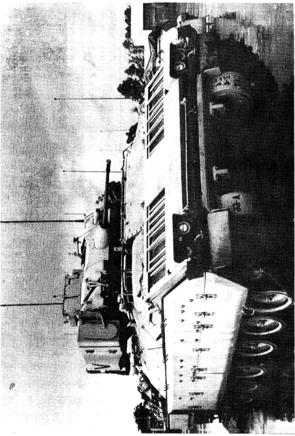
45 APPENDIX D BFVS DISASSEMBLY/REASSEMBLY PROCEDURES FOR C-141 TRANSPORT TM D-1. Introduction The BFVS may be transported on a C-141 aircraft if it does not exceed a height of inches, a width of 117 inches, and a total weight of 44,000 pounds. To meet this requirement, several items must be removed from the M2, M2A1, M3, and M3A1 vehicles. Even more items must be removed from the M2A2 and M3A2 vehicles. This appendix gives detailed guidance on how to meet the requirements for an M2A2 vehicle. These guidelines can be adapted to meet the requirements for the different BFVS and the operational needs of the military unit. To deploy M2A2 vehicles on a C 141, significant disassembly of the vehicles is required. This document details the specific disassembly and assembly procedures. The Immediate Ready Company (IRC) Mechanized Infantry Platoon is to disassemble and reassemble the BFVS unsupported except for what they carry with them. For optimum efficiency, the infantry platoon leader should divide the platoon into three teams two hull teams and a turret team. Except where noted, the teams perform their tasks at the same time. The platoon deploys with a 6,000-pound forklift and operator from the Mechanized Support Battalion Supply Company and two portable A-frames and chain hoists (which are themselves disassembled for deployment) and a 2.5-ton hydraulic jack per M2A2. Once disassembled, the BFVS components are shipped on USAF 463L pallets, labeled A and B. The A pallet consists of components that are required to render the vehicle combat capable. The platoon could, in an emergency, fight the BFVS after assembling only the A pallet items. The B pallet consists mostly of the armor plates, along with the remainder of the items to make the BFVS complete. Components are stored on both pallets with the heaviest items toward the center and the other items distributed evenly around the pallet allowing a 2-inch margin around the edge. Hard to identify items are numbered both on the part removed and on the place it goes on the M2A2 with a permanent marker. These numbers appear in the text. Obvious items, such as hatches, are not numbered. Wherever possible, the text has been augmented with photographs of the IRC soldiers carrying out the tasks and line drawings from the manuals. D-2. Disassembly Note: Before beginning disassembly, refer to tables 1 and Front hull armor plate (a three-person operation). Using two people, loosen lower front hull armor 15/16-inch bolts. Remove lower front hull armor. Reinstall four each lower front hull armor bolts for stability. Then loosen upper left front hull armor plate bolts while one person holds center plate in place with feet. Remove upper left plate. Remove 15/16-inch bolts from center plate and remove left center plate. Repeat steps for right side. 2. Mine armor plate. Insert hydraulic jack under vehicle and raise the jack to stabilize mine armor plate. Remove 15/16-inch bolts. Lower jack with three people holding plate in place and roll jack and plate out from under vehicle mm battle/feeder and receiver assembly. Unlock barrel lock in front of feed assembly. Twist barrel in opposite direction of arrow and remove. For feeder and receiver assembly, adjust barrel elevation to position 25 roils. Unlock feed tray mechanism. Use a two-person lift and twist receiver in a counterclockwise motion. Align the slotted indents with receiver lugs and slide receiver out, using an upward and out motion. Secure in black box, using straps. Screw cover onto box. 4. Air intake grill. Using two people and a hoist, loosen 3/4-inch bolts. Remove grill, making sure not to damage rubber seal. 5. Engine access cover. Using a three-person lift and a hoist, remove two each ¾-inch bolts from the engine access door and install lift and eye mount. Loosen 15/16-inch bolts and remove engine access door (during the lifting of the engine access door, be careful not to damage the outer seal). 6. Side skirt armor. Three people are required for this job. Two hold the skirt in place while the third loosens the 11/16-inch bolts. The skirt is then removed by the two people holding it. 7. Cargo hatch. Using two guide people and a hoist, loosen 15/16-inch bolts and remove hatch slowly. Remove six each shims. 8. Driver s hatch. Using two guide people and a hoist, loosen three each 15/16-inch bolts and remove hatch slowly. Remove shims and spacers. D-1

46 Figure D-1 MINE ARMOR PLATE BEING REMOVED WITH 2-1/2 TON JACK Figure D-2 9. Gunner s and commander s hatch. Using two 11. Front hull halfmoon armor. Remove three guide people and a hoist, loosen the 3/4-inch bolts each 3/4-inch bolts and remove plate. and remove hatch slowly. Remove box, 12. Headlight assemblies. Loosen four each 9/ Sponson boxes. Disconnect electrical male and inch bolts, disconnect electrical wires, and remove female connectors. TWO people hold box in place, headlights, and one loosens 15 /16-inch bolts. Remove box, 13. Maintenance platform. Using a two-person lift, D-2
47 loosen two each wing nuts and remove platform. 14. Swim tripods. Using two people, loosen straps and wing nuts and remove brackets. 15. ISU ballistic cover. Use a 12-inch adjustable wrench and disconnect two each cables. Remove five ¾-inch screws. Using a two-person lift and a hoist, remove the cover. 16. ISU. Remove 14 9/16-inch bolts. Using a two-person lift, remove ISU, being careful not to bump ISU, as this could knock it out of alignment or break the mirrors. Place in yellow ISU box and secure into position with bolts. Screw lid onto the ISU box. (Instructions for building an ISU box are given in table 3.) 17. Backup and secondary sights. Remove two each pins from secondary sight and remove sight. Then, remove four each allen head screws, three each 9/16-inch bolts, and backup sight tube assembly. 18. Periscopes. Remove 9/16-inch mounting bolts. Figure D-3 Take off each spacer and bracket and remove periscopes. Place eye covers over scopes. 19. Matching unit. Remove 9/16-inch bolts. Disconnect cables underneath matching unit and remove matching unit. 20. Snub the vehicle: Using railroad tie or like large piece of wood, run over each road wheel individually. Attach one each bracket, cable, and pin. Proceed until all 12 road wheels are snubbed. 21. Road wheels. Using eight each 2 by 4 s that are 6 inches long, place blocks in front of road wheels. Drive forward onto blocks. Remove 15/16- inch nuts and washers and remove road wheels. Reinstall nuts and washers with 15/16-inch deep well socket (so they do not get lost). 22. Turret armor. Using two or three people, remove ¾-inch bolts and 8-mm allen head screws and remove turret armor. (Caution: Some plates are double plated and heavy!). 23. Right side grenade launcher. Loosen ¾-inch D-3
 to shackles (3, 4) on access door (2). c. Install adjustable leg of sling (1) on lifting eye (5). WARNING!")
48 ATTACH TO ACCESS DOOR (2) AND LIFTING DEVICE. HAVE HELPER ASSIST. a. Install two shackles (3, 4) in two lifting eyes on access door (2). b. Install two non-adjustable legs of sling (1) to shackles (3, 4) on access door (2). c. Install adjustable leg of sling (1) on lifting eye (5). WARNING! CAUTION: NOTE: Power unit bolted Hydraulic parts can be Screws are different beam and access door damaged when sup- lengths. Note proper can fall and injure you porting bolted beam location when removif not removed properly. Be sure lifting device is attached before screws are removed. assembly. Check that parts clear trestles before lowering bolted beam assembly. DO NOT LOWER ON ing screws. Some screws have multiple washers. Note num- ber of washers with screws. FLOOR. Figure D-4 bolts. Loosen male to female grenade launcher. 24. Final drive half-moon plate ends and remove Remove four each 3/4-inch bolts and remove half-moon Plates 25. Troop seats. Remove pins and remove seats. 26. BII, Remove all BII and put in box. D-4
 One kit per road wheel arm.")
49 Snubbing kit showing locally fabricated snubbing bracket, cable, and pin. (Alternate: restraining kit, part number ) One kit per road wheel arm. D-5
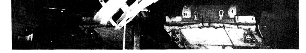
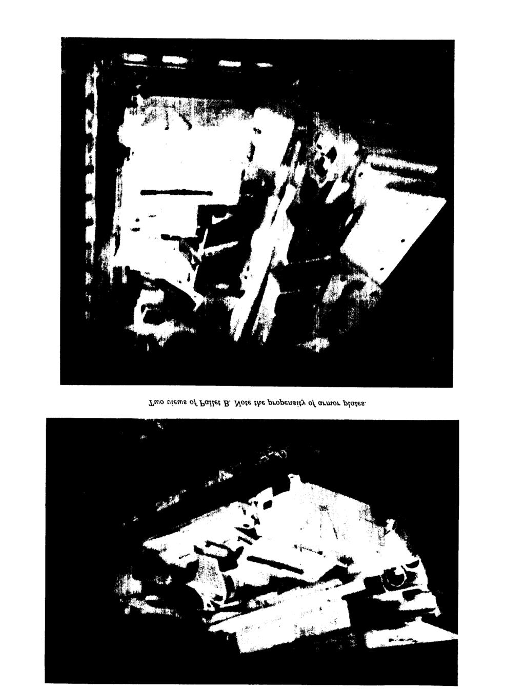
50 Turret Team 25-mm gun assembly Matching units ISU ISU ballistic cover Gunner s and commander s hatch Turret armor Grenade launcher Backup and secondary sights Periscopes Table 1. Disassembly/Reassembly Teams Tasking Hull Team # 1 Driver s hatch Cargo hatch Engine access cover Air intake grill Periscopes Sponson boxes Headlight assemblies Swim tripods Maintenance platform Hull Team # 2 Road wheels Side armor Mine armor plate Lower front hull armor plates Front hull half-moon armor Troop seats BII Final drive half-moon plate Table 2. Step-by-step Disassembly (Begin by placing 2 by 6-inch blocks under road wheels) Component (Identifying Numbers) Pallet 1. Front hull armor plates (300, 302, 303, 304, 305) B 2. Mine armor plate (301) B mm barrel and feeder and receiver assembly (306) A 4. Air intake grill (307) A 5. Engine access cover (308) A 6. Side skirt armor ( , 326, ) B 7. Cargo hatch (327) A 8. Driver s hatch A 9. Gunner s and commander s hatch (329, 332) A 10. Sponson boxes (330, 331) B 11. Front hull half-moon armor (333, 334) B 12. Headlight assemblies (335, 336) B 13. Maintenance platform (337) B 14. Swim tripods B 15. ISU ballistic cover B 16. ISU A 17. Backup and secondary sights A 18. Periscopes A 19. Matching unit A 20. Road wheels (center 4 each side) A 21. Turret armor B 22. Grenade launcher B 23. Final drive half-moon plate B 24. Troop seats B 25. BII (after all steps are completed, snub vehicle) A D-6


51 Three views of the BFVS after disassembly and snubbing. Note compressed configuration and absence of external protrusions. D-7
52 D-3. Palletizing M2A2 Components After Disassembly 1. Layout two each 463L aircraft pallets per M2A2, making sure that a 4-inch ground to pallet clearance is maintained to facilitate forklift use. 2. The placement of the load is set so that the heaviest items are centered flat and on the bottom. Stick the remaining pieces in the gaps and holes in a neat and orderly fashion, making maximum usage of all space available. Always ensure that a minimum of 2 inches is left between the edge of the load and the inner edge of the aircraft pallet. This permits aircraft personnel to walk around the edges of the pallets during flight and to recinch the load as necessary. 3. Lay a large sheet of plastic under the cargo netting and over the entire load of each pallet, making sure that the edges of the plastic are tucked in and under the edges of the load. This is not mandatory, but it does make the load more weather resistant. 4. To secure the load to the pallet, use one yellow (TOP) tiedown net and five tiedown straps on each pallet. The tiedown straps are arranged by laying two straps lengthwise and two straps widthwise, spread across evenly. The remaining strap is pulled around the diameter of the load and then all straps are cinched tightly. 5. When loading easily damaged items onto the pallets, either wrap or box them, or wrap and box them, and set them aside to be placed on top of remaining items to be palletized. When the item is very heavy or extremely flat (like the mine armor plate), it is t. be placed on the bottom of the load, to reduce the effects and damages of being topheavy and unbalanced. For example, the engine access cover has steel lines and rubber hoses for hydraulic lift assembly. These are easily damaged by crushing effects of loose or sliding armor plates. Therefore, the engine access cover needs to be placed on the bottom and shored with wood to protect the hydraulic lines. D-4. Reassembly Note: Before beginning reassembly, refer to tables 1 and Receiver and feeder assembly (a two-person operation). Unscrew all screws and take lid off black box containing the receiver and feeder assembly, Unhook straps inside box. With two people, one holding each end of the receiver and feeder assembly, take feeder and receiver out of the box, carry it into the turret of the M2A2, adjust the roils ring to 25 roils elevation, slide receiver in the direction, and align the slotted D-8 indents with the receiver lugs and slide by using an upward and in motion mm barrel (a two-person operation). Lift the barrel up, slide barrel into position, and twist barrel in the direction of the arrows. Once barrel is locked in place, check to see if barrel lock is locked by feeder assembly. 3. Matching unit (a one-person operation). Hook up ground wire, using a flat-tip screwdriver. Hook up coaxial cable. Using standard 9/16-inch screws, bolt down matching unit. 4. Road wheels (a two-person operation). Place six each 8-inch long 2 by 4 planks (taken from shoring used in aircraft) in front of road wheels. Drive the BFVS forward onto planks and unscrew bolts on road wheels. Put road wheels in place and screw bolts back in place, using a 15/16-inch deep well socket. Drive the BFVS off the boards. **Note Unsnub the vehicle at this point by using railroad tie or like large piece of wood. Run over each road wheel individually, removing one each pin and clip, and remove cable. Proceed until all 12 road wheels are unsnubbed. This must be done between steps 4 and ISU and ballistic cover (a three-person operation). Unscrew all screws from the top of the yellow box containing the ISU, take lid off, and unscrew the four bolts holding the ISU in place. Take ISU out of yellow box. Using one person in turret to guide, slowly lower ISU into place. Using 9/16-inch wrench, tighten the 14 screws. (Caution: Be sure not to bump the ISU; it could be thrown out of alignment and the mirror could break.) For the ISU ballistic cover, using two guide people and the hoist, lower cover over ISU and align ballistic cover cables in proper places. Tighten cables with 12-inch adjustable wrench. Screw in and tighten the five ¾-inch screws. 6. Drivers hatch (a two-person operation). Using two people as guides and the hoist, lower hatch into place. Using three 15/16-inch bolts, and shims plus spurs, tighten half way. Close hatch to make sure it locks, and finish tightening. 7. Gunner s and commander s hatch (a two-person operation). Using two people as guides and the hoist, lower hatch into place, placing shims under hatch, and then tighten the ¾-inch bolts half way. Close hatch to ensure correct positioning, and complete tightening. 8. Cargo hatch (a two-man operation). Using two people as guides and the hoist, lower hatch into place. Use 15/16-inch bolts, spacers, and six each shims, tighten half way. Check hatch for placement, and complete tightening.
53 Table 3. Appllcatlon of Materials for ConstructIon of Box for Integrated Sight Unit (/SU) (Figures 4-2 and 4-3) Item No. Required Material *1 4 Lumber, MIL-STD-731, Group I or II, 2 In. x 4 In. nom x 15 In. *2 2 Lumber, MIL-STD-731, Group I or II 1 In. x 4 In. nom x 13 3/4 In. *3 2 Lumber, MIL-STD-731, Group I or II, 1 in. x 4 In. nom x 21 1/8 in. *4 1 Plywood, NN-P-530, 1 In. thk x 3 In. x 16 3/4 In. *5 1 Plywood, NN-P-530, 1 in. thk x 3 in. x 16 3/4 In. *6 7 2 Plywood, NN-P-530, 1 in. thk x 2 in. x 18 3/4 In. 16 Wood screw #10, 1 In. long 8 4 Hexagon head bolt, 3/8-16 UNC-2B x 2 In. long (MS ) 9 4 Flat washer, 3/8 In. nom (MS ) 10 4 Plate nut (MS ) 11 1 Wood box, PPP-B-601, style 1,27 1/8 In. long x 18 3/4 in. wide x 32 5/8 in. deep (Inside dimensions) 12 1 Commander relay aasembly container: Wrap. MIL-A-121. Type Il. Class 2. Grade A, 28 in. wide x 33 In. long (1 piece); Cushioning, PPP-C-843, quantity as required to fill all void areas of container; Container, PPP-B-636, Style RSC, Type CF, Grade W5C, Class Weather-resistant, 10 In. long x 6 In. wide x 28 in. deep (inside dimensions); Tape, for container sealing, PPP-T-60, Type Ill, Class 1, 2 in. wide x 33 in. long (2 pieces.) 13 1 Lumber, MIL-STD-731, Group I or II, 2 In. x 4 In. nom x 9 1/8 In. * Nailing of lumber together and into container shall be per MIL-STD D-9
54 D-10
55 Table 4. Pallet Load Plans Air intake grill Pallet A Engine access cover with railroad tie Receiver and feeder assembly in box Cargo hatch Driver s hatch ISU in box Gunner s and Commander s hatches Road wheels Bolt box 25 mm barrel Litter Each troop seats MREs (six cases) protective box: Sights Periscopes BII POL products: 1 Gal GAA 5 Qt GMD Turret 1 Gal CLP 3 Qt Hydraulic FRH 4 Gal Antifreeze 5 Qt 15/40 Oil Pallet B Mine armor plate Side skirt armor Lower front hull armor plates Sponson boxes Maintenance platform Turret armor Swim tripods ISU ballistic cover Grenade launcher Front hull halfmoon armor Final drive halfmoon armor Camouflage and poles box Troop seats 9. Engine access cover (a three-person operation). Remove two each ¾-inch bolts and put eye mount on door hatch. Using three people as guides and the hoist, guide engine access cover into position and tighten two each ¾-inch bolts, Using 15/16- inch bolts, install armor and tighten bolts. 10. Air intake grill (a two-person operation). Using two people as guides and the hoist, guide grill into place (taking care to avoid damage to the rubber seal). Lower with hoist into place. Put four each 3/4-inch bolts on and tighten. 11. Turret armor (a minimum of two people on each piece). Place armor in positions with ¾-inch bolts (or 8-mm allen head screws in some spots where armor is double plated). Be very careful, as armor is heavier than it looks. 12. Grenade launcher (a one-person operation). Place launcher into position. Tighten male to female ends and insert four each ¾-inch bolts and tighten. 13. Mine armor plate (a three-person operation). Using a floor jack (provided) and a three-person lift, place armor plate onto jack. Roll jack under vehicle and raise until holes line up. Put 15/16- inch bolts in and tighten. 14. Final drive half-moon plate (a one-person operation). Put plates into position and tighten four each ¾-inch bolts (leaving one each bolt out of the left side for easy installment of front lower hull armor). 15. Lower front hull armor plate (a three-person operation). Using a three-person lift, place center left hull armor plate into position. One person positions plate with their feet, to allow the other person to put left side upper armor into position and put four each 15/16-inch bolts into place and tighten. Repeat steps for right side. Remove lower four each bolts and place lower front hull armor into place. Reinstall four each 15/16-inch bolts and tighten. 16. Side skirt armor (a two-person operation). Using a two-person lift, place each skirt into position. Use 11/16-inch bolts and tighten it down. 17. Periscopes (a one-person operation). Assemble velcro eye cover. Push periscope into place, place in bracket, and put spacer into place using 9/16- inch bolts. Tighten. 18. Backup sight and secondary sight (a oneperson operation). Unwrap backup sight and place tube assembly into position. Tighten four allen head screws and three 9/16-inch bolts on top of turret. For the secondary sight, place sight up into position, and install two pins. 19. Front headlight assemblies (a one-person operation). Place headlights into position. Put four D-11


56 D-12
57 D-13
58 each 9/16-inch bolts in holes and tighten, 20. Rear sponson boxes (a two-person operation). Using a two-person lift, put box into position, while one person installs and tightens 15/16 inch bolts and connects male to female electrical wires, being sure to match label numbers. 21. Front hull half-moon armor. Using one-person, place armor into position. Use ¾-inch bolts. Tighten. 22. Swim tripods, Using one person, place into bracket. Tighten straps and wing nuts. 23. Maintenance platform (a two-person operation). Using a two-person lift, place the platform into position, Tighten two wing bolts hand tight. 24. Troop seats, Place each seat into position. Slide pin into place, 25. BIL Unbox all BII and mount onto appropriate places. D-14


59 6,000 Pound forklift lowers engine access cover into place, guided by IRC platoon soldiers. The A-frame can also be used to perform this operation. D-15
60 Table 5. Step-by-Step Reassembly (Begin by placing 2 by 6-inch blocks under road wheels) Component (Identifying Numbers) 1. Receiver and feeder assembly mm barrel/machinegun (306) 3. Matching unit 4. Road wheels Pallet A A A A Note: Unsnub the vehicle between steps 4 and 14 ISU and ballistic cover Driver s hatch Gunner s and commander s hatch (329, 332) Cargo hatch (327) Engine access cover (308) Air intake grill (307) Turret armor Grenade launcher Mine armor plate (301) Final drive half-moon plate Lower front hull armor plate (300, ) Side skirt armor ( , 326, ) Periscopes Backup sight and secondary sight Front headlights ( ) Sponson boxes (330, 331) Front hull half-moon armor ( ) Swim tripods Maintenance platform (337) Troop seats BII A/B A A A A A B B B B B B A A B B B B B B A D-16
61 APPENDIX E TM Start the bevel cut for the top board at the 7 mark. Nail the top board to the bottom board using 6 each 10 penny nails. TOP BOARD DIMENSIONS: 2 THICKX 1l WX 14 L. BOTTOM BOARD DIMENSIONS: 2 THICKX 11 WX20 L. ALL DIMENSIONS ARE FOR COMMERCIAL GRADE LUMBER. PAINT THE TOP AND BOTTOM OF EACH BOARD WITH A NON-SKID PAINT. PAINT THE LAYER OF PEDESTAL SHORING DIRECTLY UNDER THESE TWO BOARDS WITH A NON-SKID PAINT. THE SUGGESTED PAINT IS: Walk Way Compound, "Common Non-Skid, Black, NSN E-1

62 APPLICATION OF SHORING KIT E-2
63 By Order of the Secretary of the Army: Official: GORDON R. SULLIVAN General, United States Army Chief of Staff Distribution: To be distributed in accordance with DA Form E, block 0157, Requirements for TM U.S. G.P.0. : :60058
64
65
66
67 PIN:

68 This fine document... Was brought to you by me: Liberated Manuals -- free army and government manuals Why do I do it? I am tired of sleazy CD-ROM sellers, who take publicly available information, slap watermarks and other junk on it, and sell it. Those masters of search engine manipulation make sure that their sites that sell free information, come up first in search engines. They did not create it... They did not even scan it... Why should they get your money? Why are not letting you give those free manuals to your friends? I am setting this document FREE. This document was made by the US Government and is NOT protected by Copyright. Feel free to share, republish, sell and so on. I am not asking you for donations, fees or handouts. If you can, please provide a link to liberatedmanuals.com, so that free manuals come up first in search engines: <A HREF= Military and Government Manuals</A> Sincerely Igor Chudov Chicago Machinery Movers
TRANSPORT GUIDANCE TRUCK 5-TON, 6X6 M939-SERIES/M939A1-SERIES/M939A2-SERIES HEADQUARTERS, DEPARTMENT OF THE ARMY TM
 TRANSPORT GUIDANCE TRUCK 5-TON, 6X6 M939-SERIES/M939A1-SERIES/M939A2-SERIES APPROVED FOR PUBLIC RELEASE DISTRIBUTION IS UNLIMITED HEADQUARTERS, DEPARTMENT OF THE ARMY SEPTEMBER 1993 Description M939-Series
TRANSPORT GUIDANCE FORKLIFT, 6000-LB, VARIABLE REACH, ROUGH-TERRAIN (NSN ) (ARMY MODEL MHE-269)
 (ARMY MODEL MHE-269)") TECHNICAL MANUAL TRANSPORT GUIDANCE FORKLIFT, 6000-LB, VARIABLE REACH, ROUGH-TERRAIN (NSN 3930-058-0849) (ARMY MODEL MHE-269) Approved for public release; distribution is unlimited HEADQUARTERS, DEPARTMENT
TECHNICAL MANUAL TRANSPORT GUIDANCE FORKLIFT, 6000-LB, VARIABLE REACH, ROUGH-TERRAIN (NSN 3930-058-0849) (ARMY MODEL MHE-269) Approved for public release; distribution is unlimited HEADQUARTERS, DEPARTMENT
TECHNICAL MANUAL TRANSPORTABILITY GUIDANCE GRADER, ROAD, MOTORIZED, DIESEL-ENGINE-DRIVEN (DED) HEAVY, COMMERCIAL CONSTRUCTION EQUIPMENT (CCE)
 HEAVY, COMMERCIAL CONSTRUCTION EQUIPMENT (CCE)") TECHNICAL MANUAL TRANSPORTABILITY GUIDANCE GRADER, ROAD, MOTORIZED, DIESEL-ENGINE-DRIVEN (DED) HEAVY, COMMERCIAL CONSTRUCTION EQUIPMENT (CCE) MODEL 130G MIL NSN 3805-01-150-4795 MODEL 130G TYPE I (NONSECTIONALIZED)
TECHNICAL MANUAL TRANSPORTABILITY GUIDANCE GRADER, ROAD, MOTORIZED, DIESEL-ENGINE-DRIVEN (DED) HEAVY, COMMERCIAL CONSTRUCTION EQUIPMENT (CCE) MODEL 130G MIL NSN 3805-01-150-4795 MODEL 130G TYPE I (NONSECTIONALIZED)
TRANSPORTABILITY GUIDANCE COMMERCIAL UTILITY CARGO VEHICLE (CUCV)
") TM 55-2320-289-14 TECHNICAL MANUAL TRANSPORTABILITY GUIDANCE COMMERCIAL UTILITY CARGO VEHICLE (CUCV) H E A D Q U A R T E R S, D E P A R T M E N T O F T H E A R M Y 30 JANUARY 1987 TECHNICAL MANUAL HEADQUARTERS
TM 55-2320-289-14 TECHNICAL MANUAL TRANSPORTABILITY GUIDANCE COMMERCIAL UTILITY CARGO VEHICLE (CUCV) H E A D Q U A R T E R S, D E P A R T M E N T O F T H E A R M Y 30 JANUARY 1987 TECHNICAL MANUAL HEADQUARTERS
TECHNICAL MANUAL TRANSPORTABILITY GUIDANCE TANK, COMBAT, FULL-TRACKED, M60-SERIES
 TECHNICAL MANUAL TRANSPORTABILITY GUIDANCE TANK, COMBAT, FULL-TRACKED, M60-SERIES M60 2350-00-678-5773 105-MM GUN M60A1 2350-00-756-8497 105-MM GUN M60A2 2350-00-930-3590 152-MM GUN M60A3 2350-00-148-6548
TRANSPORTABILITY GUIDANCE COMMERCIAL UTILITY CARGO VEHICLE (CUCV)
") TM 55-2320-289-14 TECHNICAL MANUAL TRANSPORTABILITY GUIDANCE COMMERCIAL UTILITY CARGO VEHICLE (CUCV) H E A D Q U A R T E R S, D E P A R T M E N T O F T H E A R M Y 30 JANUARY 1987 30 January 1987 TM 55-2320-289-14
TM 55-2320-289-14 TECHNICAL MANUAL TRANSPORTABILITY GUIDANCE COMMERCIAL UTILITY CARGO VEHICLE (CUCV) H E A D Q U A R T E R S, D E P A R T M E N T O F T H E A R M Y 30 JANUARY 1987 30 January 1987 TM 55-2320-289-14
Approved for public release; distribution is unlimited.
 TECHNICAL MANUAL TRANSPORTABILITY GUIDANCE TRACTOR, FULL-TRACKED, LOW-SPEED DIESEL-ENGINE-DRIVEN, MEDIUM DRAWBAR PULL, CATERPILLAR MODEL D7G W/WINCH (NSN 2410-01-223-7261) W/RIPPER (NSN 2410-01-223-0350)
TM TRANSPORTABILITY GUIDANCE HOWITZER, LIGHT, SELF-PROPELLED: 105-MM, M108 (NSN )
") TECHNICAL MANUAL TRANSPORTABILITY GUIDANCE HOWITZER, LIGHT, SELF-PROPELLED: 105-MM, M108 (NSN 2350-00-440-8810) HOWITZER, MEDIUM, SELF-PROPELLED: 155-MM, M109 (NSN 2350-00-440-8811) HOWITZER, MEDIUM, SELF-PROPELLED:
TECHNICAL MANUAL TRANSPORTABILITY GUIDANCE HOWITZER, LIGHT, SELF-PROPELLED: 105-MM, M108 (NSN 2350-00-440-8810) HOWITZER, MEDIUM, SELF-PROPELLED: 155-MM, M109 (NSN 2350-00-440-8811) HOWITZER, MEDIUM, SELF-PROPELLED:
TRANSPORTABILITY GUIDANCE M998 SERIES HIGH-MOBILITY MULTIPURPOSE WHEELED VEHICLES (HMMWV)
") TM 55-2320-280-14 TECHNICAL MANUAL TRANSPORTABILITY GUIDANCE M998 SERIES HIGH-MOBILITY MULTIPURPOSE WHEELED VEHICLES (HMMWV) HEADQUARTERS. DEPARTMENT OF THE ARMY AUGUST 1988 TM 55-2320-14 TM 55-2320-280-14
TM 55-2320-280-14 TECHNICAL MANUAL TRANSPORTABILITY GUIDANCE M998 SERIES HIGH-MOBILITY MULTIPURPOSE WHEELED VEHICLES (HMMWV) HEADQUARTERS. DEPARTMENT OF THE ARMY AUGUST 1988 TM 55-2320-14 TM 55-2320-280-14
The Impact of Weight and Dimensional Change on the Transportability of Military Equipment. 3 April 2003
 The Impact of Weight and Dimensional Change on the Transportability of Military Equipment 3 April 2003 Military Traffic Management Command Transportation Engineering Agency 720 Thimble Shoals Blvd, Suite
TM HEADQUARTERS, TECHNICAL MANUAL
 TECHNICAL MANUAL TRANSPORTABILITY GUIDANCE TRUCK TRACTOR, LINE-HAUL, M 915, 6x4, 14-TON (NSN 2320-01-028-4395) TRUCK TRACTOR, LINE-HAUL, M915A1, 6x4, 14-TON (NSN 2320-01-125-2640) TRUCK TRACTOR, LIGHT
TM TECHNICAL MANUAL
 TECHNICAL MANUAL TRANSPORTABILITY GUIDANCE CARRIER, CARGO, FULL-TRACKED, 7-TON, AMMUNITION, M992 (NSN 2350-01-110-4660) FIELD ARTILLERY AMMUNITION SUPPORT VEHICLE (FAASV) HEADQUARTERS, DEPARTMENT OF THE
TECHNICAL MANUAL TRANSPORTABILITY GUIDANCE GUN, FIELD ARTILLERY, SELF-PROPELLED: 175-MM, M107 (NSN )
") TECHNICAL MANUAL TRANSPORTABILITY GUIDANCE GUN, FIELD ARTILLERY, SELF-PROPELLED: 175-MM, M107 (NSN 2350-00-436-6635) HOWITZER, HEAVY, SELF-PROPELLED: 8-INCH, Ml10 (NSN 2350-00-439-6243) HOWITZER, HEAVY,
TECHNICAL MANUAL TRANSPORTABILITY GUIDANCE GUN, FIELD ARTILLERY, SELF-PROPELLED: 175-MM, M107 (NSN 2350-00-436-6635) HOWITZER, HEAVY, SELF-PROPELLED: 8-INCH, Ml10 (NSN 2350-00-439-6243) HOWITZER, HEAVY,
TM TRANSPORTABILITY GUIDANCE CLEAN BURNING DIESEL (CBD) FORKLIFT, PNEUMATIC TIRES: 4,000- (4K-) POUND CAPACITY (NSN )
 FORKLIFT, PNEUMATIC TIRES: 4,000- (4K-) POUND CAPACITY (NSN )") TECHNICAL MANUAL TRANSPORTABILITY GUIDANCE CLEAN BURNING DIESEL (CBD) FORKLIFT, PNEUMATIC TIRES: 4,000- (4K-) POUND CAPACITY (NSN 3930-01-172-7891) 6,000- (6K-) POUND CAPACITY (NSN 3930-01-172-7892) HEADQUARTERS,
TECHNICAL MANUAL TRANSPORTABILITY GUIDANCE CLEAN BURNING DIESEL (CBD) FORKLIFT, PNEUMATIC TIRES: 4,000- (4K-) POUND CAPACITY (NSN 3930-01-172-7891) 6,000- (6K-) POUND CAPACITY (NSN 3930-01-172-7892) HEADQUARTERS,
AIR TRANSPORTABILITY GUIDANCE TWO M151 1/4-TON TRUCKS AND ONE 1/4-TON TRAILER IN CH-47 HELICOPTER
 TM -2320-218-10-3 DEPARTMENT OF THE ARMY TECHNICAL MANUAL AIR TRANSPORTABILITY GUIDANCE TWO M11 1/4-TON TRUCKS AND ONE 1/4-TON TRAILER IN CH-47 HELICOPTER Headquarters, Department of the Army, Washington,
Tiedown Handbook for Truck. Movements SDDCTEA PAMPHLET FOURTH EDITION
 Tiedown Handbook for Truck Movements SDDCTEA PAMPHLET 55-20 FOURTH EDITION SDDCTEA PAMPHLET 55-19 TIEDOWN HANDBOOK FOR TRUCK MOVEMENTS FOURTH EDITION July 2008 (Electronically Revised May 2009) Michael
TRANSPORTABILITY GUIDANCE ROLAND MISSILE SYSTEM GUIDED MISSILE, INTERCEPT-AERIAL (LESS CARRIER), ROLAND FIRE UNITS (NSN W/O NBC
, ROLAND FIRE UNITS (NSN W/O NBC") TECHNICAL MANUAL TRANSPORTABILITY GUIDANCE ROLAND MISSILE SYSTEM GUIDED MISSILE, INTERCEPT-AERIAL (LESS CARRIER), ROLAND FIRE UNITS (NSN 1425-01-146-9213 W/O NBC and NSN 1425-01-144-9802 W/NBC, AN/GSG-
TECHNICAL MANUAL TRANSPORTABILITY GUIDANCE ROLAND MISSILE SYSTEM GUIDED MISSILE, INTERCEPT-AERIAL (LESS CARRIER), ROLAND FIRE UNITS (NSN 1425-01-146-9213 W/O NBC and NSN 1425-01-144-9802 W/NBC, AN/GSG-
AIR TRANSPORTABILITY GUIDANCE M151 1/4-TON TRUCK AND M100 1/4-TON TRAILER IN CH-17 HELlCOPTER
 TM 55-2320-218-10-2 DEPARTMENT OF THE ARMY TECHNICAL MANUAL AIR TRANSPORTABILITY GUIDANCE M151 1/4-TON TRUCK AND M100 1/4-TON TRAILER IN CH-17 HELlCOPTER Headquarters, Department of the Army, Washington,
THIS MANUAL SUPERSEDES TM DATED 30 MAY 1994, INCLUDING ALL CHANGES. TECHNICAL MANUAL
 THIS MANUAL SUPERSEDES TM 9-2330-385-14 DATED 30 MAY 1994, INCLUDING ALL CHANGES. TECHNICAL MANUAL OPERATOR S, UNIT, DIRECT SUPPORT AND GENERAL SUPPORT MAINTENANCE MANUAL INTRODUCTION 1-1 OPERATING INSTRUCTIONS
TECHNICAL BULLETIN OPERATOR'S AND UNIT MAINTENANCE FOR SEMITRAILER, TRANSPORTER, HEAVY EQUIPMENT 70 TON, M1000
 TECHNICAL BULLETIN OPERATOR'S AND UNIT MAINTENANCE FOR SEMITRAILER, TRANSPORTER, HEAVY EQUIPMENT 70 TON, M1000 WHEN LOADED WITH ABRAMS MAIN BATTLE TANK SERIES WITH MINE CLEARING BLADE ATTACHED Approved
ARMY TM MARINE CORPS TM 09295A-14/1 TECHNICAL MANUAL
 ARMY TM 9-2330-381-14 MARINE CORPS TM 09295A-14/1 TECHNICAL MANUAL OPERATOR'S, UNIT, DIRECT SUPPORT, AND GENERAL SUPPORT MAINTENANCE MANUAL FOR HEAVY EQUIPMENT TRANSPORTER SEMITRAILER 70 TON, M1000 NSN
TECHNICAL MANUAL TRANSPORTABILITY GUIDANCE LIGHTER, AMPHIBIAN AIR-CUSHION VEHICLE, 30-TON PAYLOAD (LACV-30)
") TECHNICAL MANUAL TRANSPORTABILITY GUIDANCE LIGHTER, AMPHIBIAN AIR-CUSHION VEHICLE, 30-TON PAYLOAD (LACV-30) This copy is a reprint which includes current pages from Change 1. HEADQUARTERS, DEPARTMENT OF
TECHNICAL MANUAL TRANSPORTABILITY GUIDANCE LIGHTER, AMPHIBIAN AIR-CUSHION VEHICLE, 30-TON PAYLOAD (LACV-30) This copy is a reprint which includes current pages from Change 1. HEADQUARTERS, DEPARTMENT OF
Blocking and Bracing for Motor Transport
 Headquarters United States Army Europe and Seventh Army United States Army Installation Management Command Europe Region Heidelberg, Germany Army in Europe Regulation 55-48* 3 July 2007 Transportation
AIR TRANSPORTABILITY GUIDANCE TWO M151 1/4-TON TRUCKS AND ONE 1/4-TON TRAILER IN CH-47 HELICOPTER
 TM -2320-218-10-3 DEPARTMENT OF THE ARMY TECHNICAL MANUAL AIR TRANSPORTABILITY GUIDANCE TWO M11 1/4-TON TRUCKS AND ONE 1/4-TON TRAILER IN CH-47 HELICOPTER Headquarters, Department of the Army, Washington,
(?6 (A 25' V 0^7 AIR TRANSPORT PROCEDURES TRANSPORT OF SPARTAN WARHEAD SECTION IN SHIPPING AND STORAGE CONTAINER, XM553, BY CH-47 HELICOPTER
 (?6 (A 2' V 0^7 ( Ref«re nc8 DEPARTMENT OF THE ARMY FM -700 FIELD MANUAL AIR TRANSPORT PROCEDURES TRANSPORT OF SPARTAN WARHEAD SECTION IN SHIPPING AND STORAGE CONTAINER, XM3, BY CH-47 HELICOPTER Headquarters,
TM HEADQUARTERS DEPARTMENT OF THE ARMY
 TRUCK TRACTOR. LINE HAUL, 50,000 GVWR, 6 X 4, M95 (NSN 0-0-08-495) TRUCK TRACTOR, LIGHT EQUIPMENT TRANSPORTER (LET), 56,000 GVWR, 6 X 6, W/WINCH, M96 (NSN 0-0-08-496) TRUCK TRACTOR, MEDIUM EQUIPMENT TRANSPORTER
ARMY TM AIR FORCE TO 36A12-1A MARINE CORPS TM /6B
 ARMY TM 9-2320-280-10 AIR FORCE TO 36A12-1A-2091-1 MARINE CORPS TM 2320-10/6B (SUPERSEDES TM 9-2320-280-10, 18 JUNE 1991) OPERATOR S MANUAL FOR TRUCK, UTILITY: CARGO/TROOP CARRIER, 1-1/4 TON, 4X4, M998
TACTICAL VEHICLES: INSTALLATION OF UNIVERSAL TIEDOWN ANCHORS
 TECHNICAL BULLETIN FOR TACTICAL VEHICLES: INSTALLATION OF UNIVERSAL TIEDOWN ANCHORS Approved for public release; distribution is unlimited. HEADQUARTERS, DEPARTMENT OF THE ARMY * TB 9-2300-280-30 Technical
TECHNICAL MANUAL UNIT MAINTENANCE MANUAL FOR TRUCK, TRACTOR, LINE HAUL 52,000 GVWR, 6 X 4, M915A2 (NSN )
") TECHNICAL MANUAL TM 9-2320-363-20-1 VOLUME NO. 1 UNIT MAINTENANCE MANUAL FOR TRUCK, TRACTOR, LINE HAUL 52,000 GVWR, 6 X 4, M915A2 (NSN 2320-01-272-5029) I TABLE I HOW OF CONTENTS TO USE THIS MANUAL I iii
TECHNICAL MANUAL TM 9-2320-363-20-1 VOLUME NO. 1 UNIT MAINTENANCE MANUAL FOR TRUCK, TRACTOR, LINE HAUL 52,000 GVWR, 6 X 4, M915A2 (NSN 2320-01-272-5029) I TABLE I HOW OF CONTENTS TO USE THIS MANUAL I iii
TM &P TECHNICAL MANUAL
 TECHNICAL MANUAL OPERATOR S, ORGANIZATIONAL, DIRECT SUPPORT, AND GENERAL SUPPORT MAINTENANCE MANUAL (INCLUDING REPAIR PARTS AND SPECIAL TOOLS LISTS) FOR TM 9-2330-359-14&P SEMITRAILER, FLATBED: BREAKBULK/CONTAINER
TM &P TECHNICAL MANUAL
 TECHNICAL MANUAL TM 9-1095-204-13&P OPERATOR S, ORGANIZATIONAL, AND DIRECT SUPPORT MAINTENANCE MANUAL (INCLUDING REPAIR PARTS AND SPECIAL TOOLS LIST) ANTITANK MINE DISPENSING SYSTEM M57 (NSN 1095-00-169-0300)
Safety. Chapter 13 SAFETY PROGRAM GENERAL SAFETY RULES
 Chapter Safety Supervisors are responsible for ensuring that personnel follow safety standards. Time is usually the controlling factor in construction operations in the theater of operations. The necessity
TM Approved for public release; distribution is unlimited
 OPERATOR S MANUAL FOR TRUCK, TRACTOR, LINE HAUL: 52,000 GVWR, 6 X 4, M915A2 (NSN 2320-01-272-5029) TRUCK, TRACTOR, LIGHT EQUIPMENT TRANSPORTER (LET): 68,000 GVWR, 6 X 6, W/WINCH, M916A1 (NSN 2320-01-272-5028)
TM OPERATOR MANUAL DRY SUPPORT BRIDGE (DSB) (NSN ) FOR. Approved for public release: distribution is unlimited
 (NSN ) FOR. Approved for public release: distribution is unlimited") OPERATOR MANUAL FOR DRY SUPPORT BRIDGE (DSB) (NSN 5420-01-469-7479) Approved for public release: distribution is unlimited April 2003 HEADQUARTERS, DEPARTMENT OF THE ARMY TECHNICAL MANUAL TM 5-5420-279-10
OPERATOR MANUAL FOR DRY SUPPORT BRIDGE (DSB) (NSN 5420-01-469-7479) Approved for public release: distribution is unlimited April 2003 HEADQUARTERS, DEPARTMENT OF THE ARMY TECHNICAL MANUAL TM 5-5420-279-10
Summary Report for Individual Task M-1501 Perform Load/Unload Operations in Automatic Mode Status: Approved
 Report Date: 05 Dec 2014 Summary Report for Individual Task 551-88M-1501 Perform Load/Unload Operations in Automatic Mode Status: Approved Distribution Restriction: Approved for public release; distribution
LOADING THE TDRT WARNING LOADING/UNLOADING OPERATION
 0012.3 00 LOADING THE TDRT WARNING LOADING/UNLOADING OPERATION All persons not involved in the loading or unloading operation must stand clear the full length of prime mover and Tilt Deck Recovery Trailer.
TM TECHNICAL MANUAL TRANSPORTABILITY GUIDANCE TRUCK, CARGO, 1-1/4-TON, 6X6, M561 (FSN )
") TECHNICAL MANUAL TRANSPORTABILITY GUIDANCE TRUCK, CARGO, 1-1/4-TON, 6X6, M561 (FSN 2320-873-5407) HEADQUARTERS DEPARTMENT OF THE ARMY OCTOBER 1973 TECHNICAL MANUAL HEADQUARTERS DEPARTMENT OF THE ARMY No.
TECHNICAL MANUAL TRANSPORTABILITY GUIDANCE TRUCK, CARGO, 1-1/4-TON, 6X6, M561 (FSN 2320-873-5407) HEADQUARTERS DEPARTMENT OF THE ARMY OCTOBER 1973 TECHNICAL MANUAL HEADQUARTERS DEPARTMENT OF THE ARMY No.
OPERATOR S MANUAL. DISTRIBUTION STATEMENT A. Approved for public release; distribution is unlimited. HEADQUARTERS, DEPARTMENT OF THE ARMY
 OPERATOR S MANUAL PREVENTIVE MAINTENANCE CHECKS AND SERVICES PAGE 2-18 OPERATION UNDER USUAL CONDITIONS PAGE 2-49 OPERATION UNDER UNUSUAL CONDITIONS PAGE 2-108 TROUBLESHOOTING PROCEDURES PAGE 3-3 MAINTENANCE
ROUTINE. MWO effective date is 1 January 2001 and completion date is 31 December MODIFICATION WORK ORDER MODIFICATION OF 1-1/4 TON VEHICLES
 ROUTINE MWO effective date is 1 January 2001 and completion date is 31 December 2004. MODIFICATION WORK ORDER MODIFICATION OF 1-1/4 TON VEHICLES HEAVY VARIANT, ARMAMENT CARRIER, AND EXPANDED CAPACITY VEHICLES
TIEDOWN HANDBOOK FOR RAIL MOVEMENTS
 MTMCTEA PAMPHLET 55-19 TRANSPORTATION AND TRAVEL TIEDOWN HANDBOOK FOR RAIL MOVEMENTS FIFTH EDITION May 2000 Mr. Robert E. Kerr Mr. Philip Raiford Mr. John T. H. Germanos LTC James McGee Ms. Jennifer L.
OPERATOR'S MANUAL CARRIER, CARGO, TRACKED, 1 /2 TON, M973 SMALL UNIT SUPPORT VEHICLE (SUSV) (NSN )
 (NSN )") OPERATOR'S MANUAL TABLE OF CONTENTS PAGE i EQUIPMENT DESCRIPTION PAGE 1-1 OPERATING INSTRUCTIONS PAGE 2-1 PREVENTIVE MAINTENANCE PAGE 2-6 CARRIER, CARGO, TRACKED, 1 /2 TON, M973 SMALL UNIT SUPPORT VEHICLE
OPERATOR'S MANUAL TABLE OF CONTENTS PAGE i EQUIPMENT DESCRIPTION PAGE 1-1 OPERATING INSTRUCTIONS PAGE 2-1 PREVENTIVE MAINTENANCE PAGE 2-6 CARRIER, CARGO, TRACKED, 1 /2 TON, M973 SMALL UNIT SUPPORT VEHICLE
SECTION 11 INTERMODAL EQUIPMENT
 SECTION 11 INTERMODAL EQUIPMENT ROA MANUAL SCHEDULE OF AMENDMENTS SECTION 11 AMENDMENT NUMBER PAGES AMENDED AMENDMENT SUMMARY DATE ISSUED TABLE OF CONTENTS Section Description Page No. 11.1 SCOPE... 11-1
TECHNICAL BULLETIN OPERATOR'S AND FIELD MAINTENANCE FOR SEMITRAILER, TRANSPORTER, HEAVY EQUIPMENT 70 TON, M1000
 TECHNICAL BULLETIN OPERATOR'S AND FIELD MAINTENANCE FOR SEMITRAILER, TRANSPORTER, HEAVY EQUIPMENT 70 TON, M1000 WHEN LOADED WITH M1 SERIES MAIN BATTLE TANK (MBT) WITH TANK URBAN SURVIVABILITY KIT (TUSK)
Internal Air Transport Certification
 Internal Air Transport Certification ASC/ENFC (ATTLA) 2530 Loop Road West WPAFB, OH 45433-7101 https://afkm.wpafb.af.mil/attla (direct) https://wwwd.my.af.mil/afknprod/attla (AF Portal) Date: 11 March
Pole Trailer Binding Requirements
 Purpose This is our response to requests for information regarding compliance with Federal Laws concerning Pole Trailer tie down systems. Background / Summary Section 393.100 of the Federal Code covers
The material incorporated by reference may be examined also at any state publications library.
 BASIS, PURPOSE AND STATUTORY AUTHORITY The basis and purpose of these rules is to provide minimum requirements for the regulation of motor vehicle safety, hours of service of drivers, and qualification
Road Service Quick Reference Guide 2016 Lincoln MKX. Quality and Education Services AAA Automotive 1000 AAA Drive Heathrow, FL 32746
 Road Service Quick Reference Guide 2016 Lincoln MKX Quality and Education Services AAA Automotive 1000 AAA Drive Heathrow, FL 32746 December 12, 2015 Index Towing, Loading and Transporting 2 Curb Weight
DEPARTMENT OF THE ARMY TECHNICAL MANUAL OPERATOR S, UNIT, INTERMEDIATE DIRECT SUPPORT AND INTERMEDIATE GENERAL SUPPORT MAINTENANCE
 TM 9-2330-380-14 & P DEPARTMENT OF THE ARMY TECHNICAL MANUAL OPERATOR S, UNIT, INTERMEDIATE DIRECT SUPPORT AND INTERMEDIATE GENERAL SUPPORT MAINTENANCE (INCLUDING REPAIR PARTS AND SPECIAL TOOLS LISTS)
DEPARTMENT OF DEFENSE
 INCH -POUND 8 January 1998 SUPERSEDING MIL-STD-09H 8 June 1991 DEPARTMENT OF DEFENSE INTERFACE STANDARD FOR LIFTING AND TIEDOWN PROVISIONS AMSC N/A FSC 540 DISTRIBUTION STATEMENT A. Approved for public
WHEEL CHOCK GUIDELINES BROCHURE
 WHEEL CHOCK GUIDELINES BROCHURE WHEEL CHOCKS FOR GROUND USE Monster Wheel Chocks comply with the safety requirements of a variety of industries and ensure a safe working environment while your vehicles
This appendix describes various types of equipment that can
 Appendix GENERAL ENGINEER SUPPORT EQUIPMENT This appendix describes various types of equipment that can be used to support general engineer missions. This information is provided to help planners choose
TECHNICAL MANUAL OPERATOR, AVIATION UNIT, AND AVIATION INTERMEDIATE MAINTENANCE MANUAL WITH REPAIR PARTS AND SPECIAL TOOLS LIST CHAPTER 1 INTRODUCTION
 EXTENDED RANGE FUEL SYSTEM ARMY MODEL CH-47 HELICOPTER TECHNICAL MANUAL OPERATOR, AVIATION UNIT, AND AVIATION INTERMEDIATE MAINTENANCE MANUAL WITH REPAIR PARTS AND SPECIAL TOOLS LIST CHAPTER 1 INTRODUCTION
CHAPTER 403. HAZARDOUS MATERIAL TRANSPORTATION
 Ch. 403 HAZARDOUS MATERIALS 67 403.1 CHAPTER 403. HAZARDOUS MATERIAL TRANSPORTATION Sec. 403.1. General information and requirements. 403.2. Definitions. 403.3. [Reserved]. 403.4. Adoption of portions
TECHNICAL BULLETIN TEST PROCEDURES
 TECHNICAL BULLETIN TEST PROCEDURES DIRECT SUPPORT AND GENERAL SUPPORT MAINTENANCE LEVELS LOAD TESTING HEAVY EXPANDED MOBILITY TACTICAL TRUCK (HEMTT) VEHICLE CRANES M977 CARGO TRUCK W/O WINCH W/GROVE MODEL
TECHNICAL MANUAL OPERATION INSTRUCTIONS CONCRETE - MOBILE MIXER BODY M919, MODEL 8CM-24/F NSN
 TECHNICAL MANUAL OPERATION INSTRUCTIONS CONCRETE - MOBILE MIXER BODY M919, MODEL 8CM-24/F NSN 3895-01-028-4391 DAFFIN MOBILE PRODUCTS DIVISION OF BARBER-GREENE COMPANY (MANUAL PREPARED BY AM GENERAL CORPORATION)
ARMY TM &P AIR FORCE TO 36A
 ARMY TM 9-2330-213-14&P AIR FORCE TO 36A11-1-461 TECHNICAL MANUAL OPERATOR S, UNIT, DIRECT SUPPORT, AND GENERAL SUPPORT MAINTENANCE MANUAL (INCLUDING REPAIR PARTS AND SPECIAL TOOLS LISTS) FOR TRAILER,
HEADQUARTERS, DEPARTMENT OF THE ARMY
 * TM 5-6115-465-10-HR DOD MODEL MEP-005A MEP-104A MEP-114A DOD MODEL MEP-005AWF MEP-005AWE MEP-005ALM MEP-005AWM HAND RECEIPT MANUAL COVERING END ITEM/COMPONENTS OF END ITEM (COEI), BASIC ISSUE ITEMS (BII)
COMBAT ENGINEER VEHICLE, M728 ( ) TM TURRET FOR TECHNICAL MANUAL
 TM TURRET FOR TECHNICAL MANUAL") TECHNICAL MANUAL CHAPTERS 13 AND 14 MAINTENANCE INSTRUCTIONS 13-1 DIRECT SUPPORT AND GENERAL SUPPORT MAINTENANCE MANUAL PART 3 MAINTENANCE TURRET FOR COMBAT ENGINEER VEHICLE, M728 (2350-00-795-1797) This
TECHNICAL MANUAL CHAPTERS 13 AND 14 MAINTENANCE INSTRUCTIONS 13-1 DIRECT SUPPORT AND GENERAL SUPPORT MAINTENANCE MANUAL PART 3 MAINTENANCE TURRET FOR COMBAT ENGINEER VEHICLE, M728 (2350-00-795-1797) This
PAGE 1 OF 6 HEALTH, SAFETY & ENVIROMENTAL MANUAL PROCEDURE: S450 Motor Vehicle Safety REV /01/09
 PAGE 1 OF 6 PURPOSE: MOTOR VEHICLE SAFETY To define the Company s requirement that drivers must possess the appropriate license for the type of vehicle to be operated and must comply at all times with
RIGGING ROAD ROLLERS C7, FM /TO 13C
 RIGGING ROAD ROLLERS C7, FM 10-528/TO 13C7-26-71 C7, FM 10-528 TO 13C7-26-71 By Order of the Secretary of the Army: Official: ERIC K. SHINSEKI General, United States Army Chief of Staff JOEL B. HUDSON
TECHNICAL BULLETIN TACTICAL WHEELED VEHICLES: REPAIR OF FRAMES
 This bulletin supersedes TB 9-2300-247-40, 23 February 1971 TECHNICAL BULLETIN TACTICAL WHEELED VEHICLES: REPAIR OF FRAMES Approved for public release; distribution is unlimited. HEADQUARTERS, DEPARTMENT
Summary Report for Individual Task M-1314 Perform Coupling Operations Status: Approved
 Report Date: 03 Mar 2015 Summary Report for Individual Task 551-88M-1314 Perform Coupling Operations Status: Approved Distribution Restriction: Approved for public release; distribution is unlimited. Destruction
TM &P TECHNICAL MANUAL
 TECHNICAL MANUAL TM 9-2330-376-14&P OPERATOR S, ORGANIZATIONAL, DIRECT SUPPORT AND GENERAL SUPPORT MAINTENANCE MANUAL (INCLUDING REPAIR PARTS AND SPECIAL TOOLS LISTS) FOR CHASSIS, TRAILER: 5-TON, 4-WHEEL,
TECHNICAL MANUAL OPERATOR AND AVIATION UNIT MAINTENANCE INSTRUCTIONS INCLUDING REPAIR PARTS AND SPECIAL TOOLS LIST FOR
 TECHNICAL MANUAL OPERATOR AND AVIATION UNIT MAINTENANCE INSTRUCTIONS INCLUDING REPAIR PARTS AND SPECIAL TOOLS LIST FOR HELICOPTER INTERNAL CARGO HANDLING SYSTEM ARMY MODEL CH47 HELICOPTER PART NUMBER:
FINAL REPORT FEBRUARY 2007 REPORT NO
 FINAL REPORT FEBRUARY 2007 REPORT NO. 06-24 TRANSPORTABILITY TESTING OF THE ENGINEER EQUIPMENT TRAILER (EET), TP-94-01, "TRANSPORTABILITY TESTING PROCEDURES" Prepared for: Distribution Unlimited: Marine
Chapter 14 SERVICING TABLE OF CONTENTS ILLUSTRATIONS
 Chapter 14 SERVICING TABLE OF CONTENTS INTRODUCTION -------------------------------------------------------------------------- 3 General ----------------------------------------------------------------------------------
CHAIN & HOOKS. Proof Coil Chain Grade 28. Transport Chain Grade 70
 Proof Coil Chain Grade 28 Proof coil chain is suitable for use as towing chain, logging,fencing, trailer safety chain, boat anchors, security barriers or other general purposes where chain of high tensile
RIGGING ROAD ROLLERS C7, FM /TO 13C
 RIGGING ROAD ROLLERS C7, FM 10-528/TO 13C7-26-71 C7, FM 10-528/TO 13C7-26-71 CHANGE 5 May 2000 NO. 7 AIRDROP OF SUPPLIES AND EQUIPMENT: RIGGING ROAD ROLLERS This change adds the procedures for rigging
TECHNICAL MANUAL ARMY AMMUNITION DATA SHEETS FOR LAND MINES (FSC 1345)
") TECHNICAL MANUAL ARMY AMMUNITION DATA SHEETS FOR LAND MINES (FSC 1345) DISTRIBUTION STATEMENT A: Approved for public release; distribution is unlimited. HEADQUARTERS, DEPARTMENT OF THE ARMY 1 SEPTEMBER
TECHNICAL MANUAL ARMY AMMUNITION DATA SHEETS FOR LAND MINES (FSC 1345) DISTRIBUTION STATEMENT A: Approved for public release; distribution is unlimited. HEADQUARTERS, DEPARTMENT OF THE ARMY 1 SEPTEMBER
TRUCK, CARGO: M35A1, M35A2, M35A2C, M36A2; TRUCK TANK, FUEL: M49A1C, M49A2C; TRUCK, TANK WATER: M50A1, M50A2, M50A3; TRUCK VAN,
 TM9-2320-209-10-1-HR HAND RECEIPT COVERING CONTENTS OF COMPONENTS OF END ITEM (COEI), BASIC ISSUE ITEMS (Bll), AND ADDITIONAL AUTHORIZATION LIST (AAL) FOR 2-1/2 TON, 6X6, M44A1 and M44A2 SERIES TRUCKS
LASHING HANDBOOK FOR MARINE MOVEMENTS
 SDDCTEA PAMPHLET 55-22 LASHING HANDBOOK FOR MARINE MOVEMENTS THIRD EDITION August 2005 (Electronically Revised July 2009) Gary Horton John T. Atwood Daniel J. Nonnemacher MILITARY SURFACE DEPLOYMENT AND
Headquarters Department of the Army Department of the Air Force
 FM 4-20.121(FM 4-20.121 and FM 10-539) TO 13C7-6-21 Airdrop of Supplies and Equipment: Rigging Tractors and Tractor-Dozers September 2007 DISTRIBUTION RESTRICTION. Approved for public release; distribution
SIDE PULL WINCHING WITH THE 35K WINCH TWO PART LINE WARNING
 0011.4 00 90 SIDE PULL WINCHING WITH THE 35K WINCH TWO PART LINE WARNING Performing a 35K Winch 90 Degree Side-Pull with the FWTRD should be performed ONLY after determining that a straight line pull configuration
Summary Report for Individual Task M-1364 Operate Vehicle with Standard, Automatic/Semiautomatic Transmission Status: Approved
 Summary Report for Individual Task 551-88M-1364 Operate Vehicle with Standard, Automatic/Semiautomatic Transmission Status: Approved Report Date: 05 Dec 2014 Distribution Restriction: Approved for public
Road Service Quick Reference Guide 2016 Lincoln MKT. Quality and Education Services AAA Automotive 1000 AAA Drive Heathrow, FL 32746
 Road Service Quick Reference Guide 2016 Lincoln MKT Quality and Education Services AAA Automotive 1000 AAA Drive Heathrow, FL 32746 December 12, 2015 Index Towing, Loading and Transporting 2 Curb Weight
MODIFICATION WORK ORDER
 CHANGE NO. 1 HEADQUARTERS DEPARTMENT OF THE ARMY Washington, D.C., 1 DECEMBER 2001 MODIFICATION WORK ORDER VEHICLE MODEL NSN Truck, Utility, 1-1/4 Ton, 4x4: Cargo/Troop Carrier M998 2320-01-107-7155 Cargo/Troop
M48A5 TANK CHASSIS, TRANSPORTING: FOR BRIDGE, ARMORED-VEHICLE-LAUNCHED SCISSORING TYPE,CLASS 60 (NSN )
") TECHNICAL MANUAL ORGANIZATIONAL MAINTENANCE This copy is a reprint which includes current pages from Changes 1 through 3. M48A5 TANK CHASSIS, TRANSPORTING: FOR BRIDGE, ARMORED-VEHICLE-LAUNCHED SCISSORING
TECHNICAL MANUAL ORGANIZATIONAL MAINTENANCE This copy is a reprint which includes current pages from Changes 1 through 3. M48A5 TANK CHASSIS, TRANSPORTING: FOR BRIDGE, ARMORED-VEHICLE-LAUNCHED SCISSORING
FINAL REPORT FOR THE C-130 RAMP TEST #3 OF A HYDREMA MINE CLEARING VEHICLE
 AFRL-RX-TY-TP-2008-4543 FINAL REPORT FOR THE C-130 RAMP TEST #3 OF A HYDREMA MINE CLEARING VEHICLE Prepared by: William R. Meldrum Mechanical Engineer Physical Simulation Team AMSRD-TAR-D U.S. Army Tank-Automotive
TM T.O. 36A12-1B
 T.O. 36A12-1B-1092-1-3 TECHNICAL MANUAL Chapter 13 VOLUME 3 OF 3 PART 2 OF 4 MAINTENANCE ORGANIZATIONAL LEVEL 2½-TON, 6x6, M44A1 AND M44A2 SERIES TRUCKS (MULTIFUEL) Chapter 14 Chapter 15 Chapter 16 TRUCK,
TM THIS MANUAL SUPERSEDES TM DATED 25 FEB 1994, INCLUDING ALL CHANGES.
 THIS MANUAL SUPERSEDES TM 9-2320-364-10 DATED 25 FEB 1994, INCLUDING ALL CHANGES. OPERATOR S MANUAL HOW TO USE THIS MANUAL iii EQUIPMENT DESCRIPTION 1-9 OPERATOR S CONTROLS AND INDICATORS 2-3 PREVENTIVE
Y-fl'. MINISTRY OF TRANSPORT AND COMMUNICATIONS DEPARTMENT OF MARINE ADMINISTRATION
 MINISTRY OF TRANSPORT AND COMMUNICATIONS DEPARTMENT OF MARINE ADMINISTRATION No-363/421, Corner of Merchant & Theinbyu Road, Botataung Township, Yangon, Myanmar E-mail : d gdma.mm@ gmail.com; dma.myan@smail.com
AIRDROP OF SUPPLIES AND EQUIPMENT: RIGGING FUEL DRUMS
 AIRDROP OF SUPPLIES AND EQUIPMENT: RIGGING FUEL DRUMS DISTRIBUTION RESTRICTION: Approved for public release; distribution is unlimited. HEADQUARTERS DEPARTMENTS OF THE ARMY AND THE AIR FORCE CHANGE NO.
Department of the Army, 1 September Section I. INTRODUCTION. Section Il. PROCEDURES
 DEPARTMENT OF THE ARMY TECHNICAL BULLETIN *TB 9-352 LOAD-TESTING VEHICLES USED TO HANDLE MISSILES AND ROCKETS MEDIUM WRECKER M62, MEDIUM WRECKER TRUCK M543 SERIES, AND M816; AND WRECKER-TRUCK TRACTOR M246
Proper Procedures for Loading. PUCO Transportation Enforcement Division Christopher Douglass Ph: (614)
") Proper Procedures for Loading PUCO Transportation Enforcement Division Christopher Douglass Ph: (614) 561-4366 General Requirements Applicability Who Do the Rules Apply To? The Federal Motor Carrier Safety
Proper Procedures for Loading PUCO Transportation Enforcement Division Christopher Douglass Ph: (614) 561-4366 General Requirements Applicability Who Do the Rules Apply To? The Federal Motor Carrier Safety
PETROLEUM LABORATORY TESTING AND OPERATIONS
 * FM 10-67-2 Field Manual No. 10-67-2 HEADQUARTERS DEPARTMENT OF THE ARMY Washington, DC, 2 April 1997 PETROLEUM LABORATORY TESTING AND OPERATIONS Table of Contents Page PREFACE CHAPTER 1 I CHAPTER 2 I
Road Service Quick Reference Guide 2016 Lincoln MKC. Quality and Education Services AAA Automotive 1000 AAA Drive Heathrow, FL 32746
 Road Service Quick Reference Guide 2016 Lincoln MKC Quality and Education Services AAA Automotive 1000 AAA Drive Heathrow, FL 32746 December 12, 2015 Index Towing, Loading and Transporting 2 Curb Weight
TM DIRECT SUPPORT AND GENERAL SUPPORT MAINTENANCE MANUAL FOR. HEADQUARTERS, DEPARTMENT OF THE ARMY August 1978 Change 2
 DIRECT SUPPORT AND GENERAL SUPPORT MAINTENANCE MANUAL FOR HULL, SUSPENSION, AND MISCELLANEOUS HULL COMPONENTS OF THE ARMORED RECONNAISSANCE/AIRBORNE ASSAULT VEHICLE: FULL-TRACKED, 152-MM GUN/LAUNCHER M551A1
TECHNICAL MANUAL M149A2. This manual supersedes TM &P, dated February 1981, and all changes.
 TECHNICAL MANUAL TM 9-2330-267-14&P OPERATOR S, ORGANIZATIONAL, DIRECT SUPPORT, AND GENERAL SUPPORT MAINTENANCE MANUAL (INCLUDING REPAIR PARTS AND SPECIAL TOOLS LISTS) FOR TRAILER, TANK, WATER: 400 GALLON,
UT30MK2 & MT30 Unmanned and Manned Turrets
 ELBIT SYSTEMS - LAND AND C 4 I ARMORED VEHICLES SOLUTIONS UT30MK2 & MT30 Unmanned and Manned Turrets Combat-proven firepower for armored personnel carriers, fully overhead without compromising troop safety
TM M977SERIES,8x8HEAVY EXPANDED MOBILITY TACTICAL TRUCKS (HEMTT) MAINTENANCE INSTRUCTIONS HEADQUARTERS, DEPARTMENT OF THE ARMY
 MAINTENANCE INSTRUCTIONS HEADQUARTERS, DEPARTMENT OF THE ARMY") TECHNICAL MANUAL MAINTENANCE INSTRUCTIONS DIRECT SUPPORT AND GENERAL SUPPORT M977SERIES,8x8HEAVY EXPANDED MOBILITY TACTICAL TRUCKS (HEMTT) MODEL NSN TRUCK, CARGO, WITH WINCH M977 2320-01-097-0260 TRUCK,
TECHNICAL MANUAL MAINTENANCE INSTRUCTIONS DIRECT SUPPORT AND GENERAL SUPPORT M977SERIES,8x8HEAVY EXPANDED MOBILITY TACTICAL TRUCKS (HEMTT) MODEL NSN TRUCK, CARGO, WITH WINCH M977 2320-01-097-0260 TRUCK,
Up-Armored HMMWV CASEVAC Conversion Kit (UAH-CCK)
") M1114 Up-Armored HMMWV CASEVAC Conversion Kit (UAH-CCK) Operation Performance Measures Place CCK Into Operation Task: Conditions & Standard (1) Given one UAH with CCK installed and stored. (2) Two trained
M1114 Up-Armored HMMWV CASEVAC Conversion Kit (UAH-CCK) Operation Performance Measures Place CCK Into Operation Task: Conditions & Standard (1) Given one UAH with CCK installed and stored. (2) Two trained
TB TECHNICAL BULLETIN
 TECHNICAL BULLETIN INSTRUCTIONS TO CONVERT T130E1 TRACK TO T150F TRACK USING KIT 57K4269(2530-01-502-3401) ON M113A3 FOV CARRIERS, M113A2 FOV CARRIERS, M548A1/A3 CARRIERS AND OSV/MBT VEHICLES DISTRIBUTION
 www.cdltest-answers.com Commercial Drivers License Transporting Passengers Test - Practice Introduction This study guide contains eighty three commercial drivers license transporting passengers test questions
CLEARWATER FIRE & RESCUE TRAINING BUREAU
 CLEARWATER FIRE & RESCUE TRAINING BUREAU TILLER OPERATOR TASK BOOK #4 Candidate Name (printed) Signature Beginning Date Candidate Station/Shift 08# Hire Date Lieutenant (print) Signature Completion date
Wallace Tri-Adjustable Gantry Cranes Square Tube Assembly Instructions
 Wallace Tri-Adjustable Gantry Cranes Square Tube Assembly Instructions For any additional information, Please call 1- S 1. Read and understand instructions before using this gantry. 2. Inspect gantry thoroughly
DEPARTMENT OF THE ARMY TECHNICAL BULLETIN UNIT LEVEL MAINTENANCE INFORMATION ON CARTRIDGE, 40MM: DUMMY, M922A1
 TB 9-1300-279-12 DEPARTMENT OF THE ARMY TECHNICAL BULLETIN UNIT LEVEL MAINTENANCE INFORMATION ON CARTRIDGE, 40MM: DUMMY, M922A1 Headquarters, Department of the Army, Washington, DC 10 May 1993 REPORTING
DU-ALL SAFETY FORKLIFT TRUCK OPERATORS TRAINING COURSE WRITTEN TEST PART 1 OPERATOR S NAME DATE
 DU-ALL SAFETY FORKLIFT TRUCK OPERATORS TRAINING COURSE WRITTEN TEST PART 1 OPERATOR S NAME DATE MULTIPLE CHOICE (select the answer which is most correct and circle the letter.) 1. A lift truck training
"Semitrailer." A trailer so constructed that some part of its weight rests upon or is carried by the towing vehicle.
 Pennsylvania: 102. Definitions. Subject to additional definitions contained in subsequent provisions of this title which are applicable to specific provisions of this title, the following words and phrases