LED Emergency Drivers
|
|
|
- Helena Sims
- 5 years ago
- Views:
Transcription


1 LED Emergency Drivers 30 YEARS OF EXCELLENCE Since 1985
2 Incorporated in the state of California in 1985, McWong International, Inc. has grown to become a strategic supplier of high-quality lighting control equipment and related electrical components. For over 30 years, we have provided to our customers an unparalleled mix of innovation, quality, and service. Today, the pace of technological change has quickened and competition continues to intensify. We are meeting these challenges through heightened investment in capable individuals, promising technologies, and advanced manufacturing facilities. 2
3 Table of Contents Product Listings LED Emergency Driver: Linear Case LED Emergency Driver: Rectangular Case...12 LED Emergency Driver: Extra Compact Driverless LED Emergency..24 Additional Resources Other Product Lines Limited Warranty Visit our website to learn more about how McWong s LED Emergency Drivers can benefit your company. 3


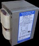
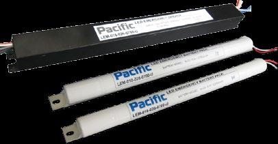
4 E LED Emergency Drivers: Linear Case 4 McWong s LEM series of LED Emergency Drivers is designed to provide emergency backup power for safety compliance to UL 924; CAN/CSA-C22.2 No and NFPA requirements for 90 minute egress. This product replaces emergency fluorescent ballasts when fixtures are converted from fluorescent to LED light sources, or for new LED luminaires. Standard installations require three separate parts to function: One non-emergency LED driver (AC input) One LEM series LED emergency driver One set of two NiCd battery packs Emergency-only installations require two separate parts: One LEM series LED emergency driver One set of two NiCd battery packs Standard Features: Safety compliance to UL 924; CAN/CSA- C22.2 No and NFPA requirements for 90 minute egress Open circuit / short circuit protection Operating temperature: 32 F/0 C to 122F/50 C Test switch / charging indicator light Emergency reaction time 1 sec Powder coat steel, stainless or galvannealed case Field-replaceable NiCd battery pack (x2) with quick connect Min. Lead length: 6 UL1452 solid/18awg 1000V/90 C UL Recognized as: Suitable for Use in Damp Locations
5 How to Order LEM U Input Voltage U = Universal VAC Operating Current: 0700 = 700mA Max Output Voltage: 026 = 26VDC 028 = 28VDC 056 = 56VDC Wattage & Case Type: 0xx = Linear Case Mxx = Rectangular Case Cxx = Extra Compact Case Dxx = Driverless x07 = 7W x18 = 18W Product Series: LEM = LED Emergency Driver Model No.* Input Voltage Output Power Output Voltage Output Current Battery Voltage Battery Capacity Recharge Time Default Battery Pack* UL (VAC) (W) (VDC) (ma) (VDC) (Ah) (hr) LEM U x BCP-NiCd L LEM U x BCP-NiCd L LEM U x BCP-NiCd L *Each LED emergency driver model is assigned a default set of battery packs, which are automatically included with your order. Other battery pack options are available, but must be special ordered. This product series is optimized for use with McWong s LED modules. For questions regarding compatibility with light sources from other manufacturers please contact technical support. 5 McWong International, Inc Arena Blvd., Sacramento, CA Tel: support@mcwonginc.com Web:
6 LED Emergency Drivers: Linear Case E Dimensions: LEM U LEM Driver LEM U 31 mm 337 mm 356 mm 25 mm Battery Pack BCP-NiCd L Dia. 21 mm 20 mm 2 mm 270 mm 320 mm Model No. Max Overall Length Width Height Mounting Centers Min Lead Length Weight 6 (in) (mm) (in) (mm) (in) (mm) (in) (mm) (in) (mm) (lbs) LEM U BCP-NiCd L* *The driver and battery packs are a matched set, which are automatically paired together when you order. Other battery pack options are available, but must be special ordered.
7 LED Emergency Drivers: Linear Case E Wiring Diagrams: LEM U Switched or Line Wiring Diagram Configuration #1: Shared Load AC LED Driver Configuration #1: Shared Load / / Fuse / Test Switch BRN PRP GRA LEM-xxx Series Emergency LED Driver Charge Indicator / LED+ YLW LED- YLW/ Battery Pack 1 of 2 Battery Pack 2 of 2 Switched or Line Wiring Diagram Configuration #2: Partial Load AC LED Driver Configuration #2: Partial Load / / Fuse / Test Switch BRN PRP GRA LEM-xxx Series Emergency LED Driver Charge Indicator / LED+ YLW LED- YLW/ Battery Pack 1 of 2 Battery Pack 2 of 2 Wiring Diagram Configuration #3: Separate Emergency / AC Loads Configuration #3: Separate Emergency / AC Loads Switched or Line / / Fuse Battery Pack 1 of 2 / OPTIONAL (Not required for Emergency Only applications) AC LED Driver Test Switch BRN PRP GRA LEM-xxx Series Emergency LED Driver Charge Indicator / Battery Pack 2 of 2 LED+ YLW LED- YLW/ 7 McWong International, Inc Arena Blvd., Sacramento, CA Tel: support@mcwonginc.com Web:
8 LED Emergency Drivers: Linear Case E Dimensions: LEM U LEM Driver LEM U 31 mm 337 mm 356 mm 25 mm Battery Pack BCP-NiCd L Dia. 25 mm 21 mm 2 mm 340 mm 388 mm Model No. Max Overall Length Width Height Mounting Centers Min Lead Length Weight 8 (in) (mm) (in) (mm) (in) (mm) (in) (mm) (in) (mm) (lbs) LEM U BCP-NiCd L* *The driver and battery packs are a matched set, which are automatically paired together when you order. Other battery pack options are available, but must be special ordered.
9 LED Emergency Drivers: Linear Case E Wiring Diagrams: LEM U Switched or Line Wiring Diagram Configuration #1: Shared Load AC LED Driver Configuration #1: Shared Load / / Fuse / Test Switch BRN PRP GRA LEM-xxx Series Emergency LED Driver Charge Indicator / LED+ YLW LED- YLW/ Battery Pack 1 of 2 Battery Pack 2 of 2 Switched or Line Wiring Diagram Configuration #2: Partial Load AC LED Driver Configuration #2: Partial Load / / Fuse / Test Switch BRN PRP GRA LEM-xxx Series Emergency LED Driver Charge Indicator / LED+ YLW LED- YLW/ Battery Pack 1 of 2 Battery Pack 2 of 2 Wiring Diagram Configuration #3: Separate Emergency / AC Loads Configuration #3: Separate Emergency / AC Loads Switched or Line / / Fuse Battery Pack 1 of 2 / OPTIONAL (Not required for Emergency Only applications) AC LED Driver Test Switch BRN PRP GRA LEM-xxx Series Emergency LED Driver Charge Indicator / Battery Pack 2 of 2 LED+ YLW LED- YLW/ 9 McWong International, Inc Arena Blvd., Sacramento, CA Tel: support@mcwonginc.com Web:
10 LED Emergency Drivers: Linear Case E Dimensions: LEM U LEM Driver LEM U 31 mm 337 mm 356 mm 25 mm Battery Pack BCP-NiCd L Dia. 25 mm 20 mm 2 mm 388 mm 440 mm Model No. Max Overall Length Width Height Mounting Centers Min Lead Length Weight 10 (in) (mm) (in) (mm) (in) (mm) (in) (mm) (in) (mm) (lbs) LEM U BCP-NiCd L* *The driver and battery packs are a matched set, which are automatically paired together when you order. Other battery pack options are available, but must be special ordered.
11 LED Emergency Drivers: Linear Case E Wiring Diagrams: LEM U Switched or Line Wiring Diagram Configuration #1: Shared Load AC LED Driver Configuration #1: Shared Load / / Fuse / Test Switch BRN PRP GRA LEM-xxx Series Emergency LED Driver Charge Indicator / LED+ YLW LED- YLW/ Battery Pack 1 of 2 Battery Pack 2 of 2 Switched or Line Wiring Diagram Configuration #2: Partial Load AC LED Driver Configuration #2: Partial Load / / Fuse / Test Switch BRN PRP GRA LEM-xxx Series Emergency LED Driver Charge Indicator / LED+ YLW LED- YLW/ Battery Pack 1 of 2 Battery Pack 2 of 2 Wiring Diagram Configuration #3: Separate Emergency / AC Loads Configuration #3: Separate Emergency / AC Loads Switched or Line / / Fuse Battery Pack 1 of 2 / OPTIONAL (Not required for Emergency Only applications) AC LED Driver Test Switch BRN PRP GRA LEM-xxx Series Emergency LED Driver Charge Indicator / Battery Pack 2 of 2 LED+ YLW LED- YLW/ 11 McWong International, Inc Arena Blvd., Sacramento, CA Tel: support@mcwonginc.com Web:

 One LEM series LED emergency driver One set of two NiCd battery packs")

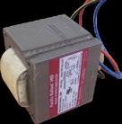
12 LED Emergency Drivers: Rectangular Case 12 McWong s LEM series of LED Emergency Drivers is designed to provide emergency backup power for safety compliance to UL 924; CAN/CSA-C22.2 No and NFPA requirements for 90 minute egress. This product replaces emergency fluorescent ballasts when fixtures are converted from fluorescent to LED light sources, or for new LED luminaires. Standard installations require three separate parts to function: One non-emergency LED driver (AC input) One LEM series LED emergency driver One set of two NiCd battery packs Emergency-only installations require two separate parts: One LEM series LED emergency driver One set of two NiCd battery packs Standard Features: Safety compliance to UL 924; CAN/CSA- C22.2 No and NFPA requirements for 90 minute egress Open circuit / short circuit protection Operating temperature: 32 F/0 C to 122F/50 C Test switch / charging indicator light Emergency reaction time 1 sec Powder coat steel, stainless or galvannealed case Field-replaceable NiCd battery pack (x2) with quick connect Min. Lead length: 6 UL1452 solid/18awg 1000V/90 C
13 How to Order LEM - M U Input Voltage U = Universal VAC Operating Current: 0350 = 350mA Max Output Voltage: 056 = 56VDC Wattage & Case Type: 0xx = Linear Case Mxx = Rectangular Case Cxx = Extra Compact Case Dxx = Driverless x07 = 7W x18 = 18W Product Series: LEM = LED Emergency Driver Model No.* Input Voltage Output Power Output Voltage Output Current Battery Voltage Battery Capacity Recharge Time Default Battery Pack* UL (VAC) (W) (VDC) (ma) (VDC) (Ah) (hr) LEM-M U x BCP-NiCd M LEM-M U x BCP-NiCd M *Each LED emergency driver model is assigned a default set of battery packs, which are automatically included with your order. Other battery pack options are available, but must be special ordered. This product series is optimized for use with McWong s LED modules. For questions regarding compatibility with light sources from other manufacturers please contact technical support. 13 McWong International, Inc Arena Blvd., Sacramento, CA Tel: support@mcwonginc.com Web:
 (mm) (in) (mm) (in) (mm) (in) (mm) (in) (mm) (lbs) LEM-M10-028-0350-U 7.8 199 2.1 53 1.3 33 7.6 193 10.2 260 0.")
14 LED Emergency Drivers: Rectangular Case E Dimensions: LEM-M U LEM Driver LEM-M U Battery Pack BCP-NiCd M MAX 133 MAX Model No. Max Overall Length Width Height Mounting Centers Min Lead Length Weight (in) (mm) (in) (mm) (in) (mm) (in) (mm) (in) (mm) (lbs) LEM-M U BCP-NiCd M* *The driver and battery packs are a matched set, which are automatically paired together when you order. Other battery pack options are available, but must be special ordered.
15 LED Emergency Drivers: Rectangular Case E Wiring Diagrams: LEM-M U Switched or Line Wiring Diagram Configuration #1: Shared Load AC LED Driver Configuration #1: Shared Load / / Fuse / Test Switch BRN PRP GRA LEM-xxx Series Emergency LED Driver Charge Indicator / LED+ YLW LED- YLW/ Battery Pack 1 of 2 Battery Pack 2 of 2 Switched or Line Wiring Diagram Configuration #2: Partial Load AC LED Driver Configuration #2: Partial Load / / Fuse / Test Switch BRN PRP GRA LEM-xxx Series Emergency LED Driver Charge Indicator / LED+ YLW LED- YLW/ Battery Pack 1 of 2 Battery Pack 2 of 2 Wiring Diagram Configuration #3: Separate Emergency / AC Loads Configuration #3: Separate Emergency / AC Loads Switched or Line / / Fuse Battery Pack 1 of 2 / OPTIONAL (Not required for Emergency Only applications) AC LED Driver Test Switch BRN PRP GRA LEM-xxx Series Emergency LED Driver Charge Indicator / Battery Pack 2 of 2 LED+ YLW LED- YLW/ 15 McWong International, Inc Arena Blvd., Sacramento, CA Tel: support@mcwonginc.com Web:
16 LED Emergency Drivers: Rectangular Case E Dimensions: LEM-M U LEM Driver LEM-M U Battery Pack BCP-NiCd M Model No. Max Overall Length Width Height Mounting Centers Min Lead Length Weight 16 (in) (mm) (in) (mm) (in) (mm) (in) (mm) (in) (mm) (lbs) LEM-M U BCP-NiCd M* *The driver and battery packs are a matched set, which are automatically paired together when you order. Other battery pack options are available, but must be special ordered.
17 LED Emergency Drivers: Rectangular Case E Wiring Diagrams: LEM-M U Switched or Line Wiring Diagram Configuration #1: Shared Load AC LED Driver Configuration #1: Shared Load / / Fuse / Test Switch BRN PRP GRA LEM-xxx Series Emergency LED Driver Charge Indicator / LED+ YLW LED- YLW/ Battery Pack 1 of 2 Battery Pack 2 of 2 Switched or Line Wiring Diagram Configuration #2: Partial Load AC LED Driver Configuration #2: Partial Load / / Fuse / Test Switch BRN PRP GRA LEM-xxx Series Emergency LED Driver Charge Indicator / LED+ YLW LED- YLW/ Battery Pack 1 of 2 Battery Pack 2 of 2 Wiring Diagram Configuration #3: Separate Emergency / AC Loads Configuration #3: Separate Emergency / AC Loads Switched or Line / / Fuse Battery Pack 1 of 2 / OPTIONAL (Not required for Emergency Only applications) AC LED Driver Test Switch BRN PRP GRA LEM-xxx Series Emergency LED Driver Charge Indicator / Battery Pack 2 of 2 LED+ YLW LED- YLW/ 17 McWong International, Inc Arena Blvd., Sacramento, CA Tel: support@mcwonginc.com Web:


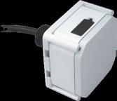
18 LED Emergency Drivers: Extra Compact 18 McWong s LEM series of LED Emergency Drivers is designed to provide emergency backup power for safety compliance to UL 924; CAN/CSA-C22.2 No and NFPA requirements for 90 minute egress. This product replaces emergency fluorescent ballasts when fixtures are converted from fluorescent to LED light sources, or for new LED luminaires. Standard installations require three separate parts to function: One non-emergency LED driver (AC input) One LEM series LED emergency driver One NiMH battery pack Emergency-only installations require two separate parts: One LEM series LED emergency driver One NiMH battery pack Standard Features: Safety compliance to UL 924; CAN/CSA- C22.2 No and NFPA requirements for 90 minute egress Open circuit / short circuit protection Operating temperature: 32 F/0 C to 122F/50 C Test switch / charging indicator light Emergency reaction time 1 sec Powder coat steel, stainless or galvannealed case Field-replaceable NiMH battery pack (x1) with quick connect Min. Lead length: 6 UL1452 solid/18awg 1000V/90 C
19 How to Order LEM - C U Input Voltage U = Universal VAC Operating Current: 0200 = 200mA 0400 = 400mA Max Output Voltage: 036 = 36VDC Wattage & Case Type: 0xx = Linear Case Mxx = Rectangular Case Cxx = Extra Compact Case Dxx = Driverless x07 = 7W x18 = 18W Product Series: LEM = LED Emergency Driver Model No.* Input Voltage Output Power Output Voltage Output Current Battery Voltage Battery Capacity Recharge Time Default Battery Pack* UL (VAC) (W) (VDC) (ma) (VDC) (Ah) (hr) LEM-C U x BCP-NiMH C LEM-C U x BCP-NiMH C *Each LED emergency driver model is assigned a default set of battery packs, which are automatically included with your order. Other battery pack options are available, but must be special ordered. This product series is optimized for use with McWong s LED modules. For questions regarding compatibility with light sources from other manufacturers please contact technical support. 19 McWong International, Inc Arena Blvd., Sacramento, CA Tel: support@mcwonginc.com Web:
20 LED Emergency Drivers: Extra Compact Dimensions: LEM-C U LEM Driver LEM-C U Battery Pack BCP-NiMH C Model No. Max Overall Length Width Height Mounting Centers Min Lead Length Weight 20 (in) (mm) (in) (mm) (in) (mm) (in) (mm) (in) (mm) (lbs) LEM-C U BCP-NiMH C* N/A N/A *The driver and battery packs are a matched set, which are automatically paired together when you order. Other battery pack options are available, but must be special ordered.
21 LED Emergency Drivers: Extra Compact Wiring Diagrams: LEM-C U Configuration #1: Shared Load Unswitched AC Test Switch + LED Violet + Brown - Black - L White - N LEM-007 Series LED Emergency Driver Red BAT + White BAT - Yellow Load + Yellow/Black Load - Blue Drv + Blue/White Drv - Battery Pack Switched AC Black - L White - N Primary AC Driver Drv - Drv + Configuration #2: Partial Load Unswitched AC Switched AC Test Switch + LED Violet + Brown - Black - L White - N Black - L White - N LEM-007 Series LED Emergency Driver Primary AC Driver Red BAT + White BAT - Yellow Load + Yellow/Black Load - Blue Drv + Blue/White Drv - Drv + Drv - Battery Pack Configuration #3: Separate Emergency / AC Loads Unswitched AC Switched AC Test Switch + LED Violet + Brown - Black - L White - N Black - L White - N LEM-007 Series LED Emergency Driver Primary AC Driver Red BAT + White BAT - Yellow Load + Yellow/Black Load - Blue Drv + Blue/White Drv - Drv + Drv - OPTIONAL (Not required for Emergency Only applications) Battery Pack 21 McWong International, Inc Arena Blvd., Sacramento, CA Tel: support@mcwonginc.com Web:
22 LED Emergency Drivers: Extra Compact Dimensions: LEM-C U LEM Driver LEM-C U Battery Pack BCP-NiMH C 22 Model No. Max Overall Length Width Height Mounting Centers Min Lead Length Weight (in) (mm) (in) (mm) (in) (mm) (in) (mm) (in) (mm) (lbs) LEM-C U BCP-NiMH C* N/A N/A *The driver and battery packs are a matched set, which are automatically paired together when you order. Other battery pack options are available, but must be special ordered.

23 LED Emergency Drivers: Extra Compact Wiring Diagrams: LEM-C U Configuration #1: Shared Load Unswitched AC Test Switch + LED Violet + Brown - Black - L White - N LEM-007 Series LED Emergency Driver Red BAT + White BAT - Yellow Load + Yellow/Black Load - Blue Drv + Blue/White Drv - Battery Pack Switched AC Black - L White - N Primary AC Driver Drv - Drv + Configuration #2: Partial Load Unswitched AC Switched AC Test Switch + LED Violet + Brown - Black - L White - N Black - L White - N LEM-007 Series LED Emergency Driver Primary AC Driver Red BAT + White BAT - Yellow Load + Yellow/Black Load - Blue Drv + Blue/White Drv - Drv + Drv - Battery Pack Configuration #3: Separate Emergency / AC Loads Unswitched AC Switched AC Test Switch + LED Violet + Brown - Black - L White - N Black - L White - N LEM-007 Series LED Emergency Driver Primary AC Driver Red BAT + White BAT - Yellow Load + Yellow/Black Load - Blue Drv + Blue/White Drv - Drv + Drv - Battery Pack OPTIONAL (Not required for Emergency Only applications) 23 McWong International, Inc Arena Blvd., Sacramento, CA Tel: support@mcwonginc.com Web:

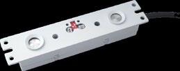
24 Driverless LED Emergency McWong s LEM-Dxx series of Driverless LED emergency products is designed to provide emergency backup power for safety compliance to UL 924; CAN/CSA-C22.2 No and NFPA requirements for 90 minute egress. This product replaces emergency fluorescent ballasts when fixtures are converted from fluorescent to LED light sources, or for new LED luminaires. Standard installations of the driverless models require two separate parts to function: One LEM-Dxx series LED emergency driver One NiCd battery pack Standard Features: Normal mode LED soft start, emergency mode conversion within 1 second Aluminum low profile housing Field-replaceable NiCd battery pack with quick connect Constant current, multi-current selectable output 0-10V dimmable Emergency mode DIP settings for 150mA, 300mA, 450mA, or 600mA output current Class I CE & UL Recognized for US and Canada. Suitable for indoor, dry and damp applications RoHS compliant (NiCd battery excepted) UL Recognized for 4 F / -20 C Contact manufacturer for Battery Pack options. 24 Safety compliance to UL 924; CAN/CSA-C22.2 No and NFPA requirements for 90 minute egress Open circuit / short circuit protection Operating temperature: 32 F/0 C to 122 F/50 C Test switch / charging indicator light
25 How to Order LEM - D P U Battery Amp-Hour Suffix Code and Max Emergency Power* 1.0 NiCd1.0Ah 9.6V (AA) Max 4W 2.0 NiCd 2.0Ah 9.6V (sc) Max 8W 4.0 NiCd 4.0Ah 9.6V (D) Max 17W Input Voltage U = Universal VAC Max Operating Current: 0600 = 600mA Max Output Voltage: 042 = 42VDC Normal Power & Case Type: 0xx = Linear Case Mxx = Rectangular Case Cxx = Extra Compact Case Dxx = Driverless x07 = 7W x18 = 18W Product Series: LEM = LED Emergency Driver Model No.* Input Voltage Max Output Power Output Voltage Range Max Output Current Battery Voltage Battery Capacity Recharge Time Emergency Operation (VAC) (W) (VDC) (ma) (VDC) (Ah) (hr) Battery Pack Options (See Emergency Power Limits above) UL Rec. LEM-D25-042P0600-U * 6 38* 600* 9.6 See specs , 2.0, 1.0 Ah LEM-D42-042P1000-U * 6 42* 600* 9.6 See specs , 2.0, 1.0 Ah Normal Operation (VAC) (W) (VDC) (ma) (VDC) (Ah) (hr) LEM-D25-042P0600-U LEM-D42-042P1000-U *Output current settings must be limited such that the product of the Emergency LED Array Voltage times the Emergency Output Current does not exceed Battery Max Emergency Power rating. The driverless LED emergency series is designed for maximum adaptability to accommodate a wide range of outputs. Driverless means that there is no need for a separate AC LED driver; i.e., both normal power and emergency power are regulated by a single self-contained, hybrid AC/emergency driver. The models in this table can be paired with several different battery packs. When ordering, you must include a suffix code to indicate the battery type desired. For questions please contact technical support. Toll Free: (888) Support@McWonginc.com 25 McWong International, Inc Arena Blvd., Sacramento, CA Tel: support@mcwonginc.com Web:
26 Driverless LED Emergency E Dimensions: LEM-D25-042P0600-U and LEM-D42-042P1000-U LEM Driver LEM-D25-042P0600-U and LEM-D42-042P1000-U W A L H Battery Pack BCP-NiCd , BCP-NiCd , and BCP-NiCd L A D W B E C Model No. L W H A B C D E Weigh t (in) (mm) (in) (mm) (in) (mm) (in) (mm) (in) (mm) (in) (mm) (in) (mm) (in) (mm) (lbs) LEM-D25-042P0600-U LEM-D42-042P1000-U BCP-NiCd BCP-NiCd BCP-NiCd *The driverless LED emergency series is designed for maximum adaptability to accommodate a wide range of outputs. Driverless means that there is no need for a separate AC LED driver; i.e., both normal power and emergency power are regulated by a single self-contained, hybrid AC/emergency driver.


27 Driverless LED Emergency E Wiring Diagrams: LEM-D25-042P0600-U and LEM-D42-042P1000-U Driverless LED Emergency 0-10V L Unswitched L Switched LEM-D25-042P0600-U/ LEM-D42-042P1000-U 0-10V X Dipswitch Settings: Dipswitches 1-3 determine the normal mode output current. LEM-D25-042P0600-U LEM-D42-042P1000-U Dipswitches 4 and 5 set various emergency current values. LEM-Dxx-042Pxxxx-U Battery Options at Typical Voltages 4 5 Iemergency Req d Battery Typical Rating mA mA mA mA 1.0Ah 12V 1.0Ah 24V 2.0Ah 36V 1.0Ah 12V 2.0Ah 24V 4.0Ah 36V 2.0Ah 12V 4.0Ah 24V 4.0Ah 36V 2.0Ah 12V 4.0Ah 24V 27 *Output current settings must be limited such that the product of the Emergency LED Array Voltage times the Emergency Output Current does not exceed Battery Max Emergency Power rating. McWong International, Inc Arena Blvd., Sacramento, CA Tel: support@mcwonginc.com Web:
28 Driverless LED Emergency E Battery Selection: LEM-D25-042P0600-U and LEM-D42-042P1000-U Battery Tables for 0 C - 50 C operation Contact manufacturer for cold weather applications (UL recognized for 20 C - 50 C) Emergency Time >90 Minutes Output Voltage 38/42VDC Battery for LEM-D25-042P0600-U Forward Emergency Current Voltage (V) 150mA 300mA 450mA 600mA Amp-Hours Amp-Hours Amp-Hours Amp-Hours N/A N/A N/A UL approved batteries: 1.0Ah Ni-Cd AA, 2.0Ah Ni-Cd SC, 4.0Ah Ni-Cd D Battery for LEM-D42-042P1000-U Forward Emergency Current Voltage (V) 150mA 300mA 450mA 600mA Amp-Hours Amp-Hours Amp-Hours Amp-Hours N/A N/A N/A N/A UL approved batteries: 1.0Ah Ni-Cd AA, 2.0Ah Ni-Cd SC, 4.0Ah Ni-Cd D 28 Note: Max. emergency output power 16.8W If your forward voltage lies in between a table value, round up and use the corresponding battery.
29 30 YEARS OF EXCELLENCE Since 1985 Notes: 20 29


30 30
31 Limited Warranty LED Emergency Drivers McWong International, Inc. (hereafter referred to as MCWONG ), corporate headquarters located at 1921 Arena Blvd., Sacramento, CA 95834, warrants its products to be free from defects in materials and workmanship from the date of manufacture for the following time periods: Product Series LED Emergency Drivers (all types) Warranty 60 months MCWONG cannot assume any obligations or liabilities for consequential or incidental damages arising from, or in connection with, the use or performance of its products or other indirect damages with respect to loss of property, revenue or profit, or cost of removal, installation or reinstallation. This limited warranty is not applicable to any product subjected to abnormal stress, such as improper storage, installation, use and/or maintenance. This warranty is invalid for any product not installed and operated in accordance with all relevant federal, state, and local government regulations, established industry safety standards, published electrical and temperature ratings, and any specific instructions provided by MCWONG for the installation of the product(s). This limited warranty is extended by MCWONG only to the original or first end-user purchaser. The standards and conditions of any tests performed on any MCWONG product(s) by the original purchaser, or by any third party acting on behalf of the original purchaser, shall be mutually agreed upon in writing and MCWONG shall be notified of, and may be represented at any such tests. Should defects occur after installation, and within the warranty period, they should be specifically described to a MCWONG representative. MCWONG shall correct any defects, at MCWONG s option, by furnishing materials to repair or replace any product(s) that may prove defective in materials or workmanship within the warranty period, or by extending a credit in the amount of the purchase price. This does not apply to: (1) damage caused by accident, abuse, mishandling, or dropping; (2) materials which have been subject to unauthorized repair; (3) materials not used in accordance with instructions; (4) ordinary wear and tear. MCWONG will be limited to the furnishing of new parts, free of charge, or extending credit for in the amount of the purchase price, in exchange for parts proven to be defective and does not include any other costs of removal or installation. This limited warranty constitutes the sole and exclusive remedy of the purchase and the exclusive liability of MCWONG, and is in lieu of any and all other warranties, expressed, implied, or statutory as to merchantability, fitness for purpose sold, description, quality productiveness, or any other matter. NO IMPLIED STATUTORY WARRANTY OF MERCHANTABILITY OR FITNESS FOR A PARTICULAR PURPOSE SHALL APPLY BEYOND THE AFOREMENTIONED WARRANTY PERIOD. Warranty claims can be submitted by calling our toll free technical support hotline (888) or by visiting our website and filling out a Warranty Replacement Form (Click on Support >> Warranty Statements). Completed forms should be faxed to (916) or ed to Support@McWonginc.com. 31

32 McWong International, Inc Arena Blvd., Sacramento, CA Tel: Fax: Web: Copyright 2016 McWong International, Inc. Specifications subject to change without notice V3.00
LED Emergency Drivers
 LED Emergency Drivers Incorporated in the state of California in 1985, McWong International, Inc. has grown to become a strategic supplier of high-quality lighting control equipment and related electrical
LED Emergency Drivers
 LED Emergency Drivers McWong Interna onal, Inc. 1921 Arena Blvd., Sacramento, CA 95834 Tel: 916-371-8080 Fax: 916-371-6666 Email: support@mcwonginc.com Web: www.mcwonginc.com Copyright 2015 McWong Interna
LED Auxiliary Devices
 LED Auxiliary Devices 30 YEARS OF EXCELLENCE 1985-2015 Incorporated in the state of California in 1985, McWong International, Inc. has grown to become a strategic supplier of high-quality lighting control
LED Auxiliary Devices
 LED Auxiliary Devices 30 YEARS OF EXCELLENCE Since 1985 Incorporated in the state of California in 1985, McWong International, Inc. has grown to become a strategic supplier of high-quality lighting control
LED Drivers and Modules
 LED Drivers and Modules 30 YEARS OF EXCELLENCE Since 1985 Incorporated in the state of California in 1985 McWong International, Inc. has grown to become a strategic supplier of high-quality lighting control
Type Flexair Pneumatic Pressure Control Valves
 Industrial Hydraulics Electric Drives and Controls Linear Motion and Assembly Technologies Pneumatics Service Automation Mobile Hydraulics Type Flexair Pneumatic Pressure Control Valves Catalog pages from
Series 2100 Operating Instructions
 Series 2100 Operating Instructions Installation Instructions Visit the link below or scan the QR code to watch a detailed installation video: http://triteqlock.com/fresh After the lock, temperature probe,
Open Display Merchandiser Installation and Operation Manual Please read this manual completely before attempting to install or operate this equipment!
 Turbo Air Speed up the Pace of Innovation CAUTION! PLEASE KEEP POWER SWITCH ON BEFORE OPERATING THIS EQUIPMENT Open Display Merchandiser Installation and Operation Manual Please read this manual completely
HBC-20 - LED HIGH BAY
 To prevent death, injury or damage to property, this product must be installed in accordance to National Electrical Code (NFPA70) in the US or Canadian Electrical Code (CSA.) in Canada. Risk of fire or
PVI 1800/PVI Residential/Commercial Grid-Tied Photovoltaic Inverter WARRANTY MANUAL. Subject to Change REV , Solectria Renewables
 PVI 1800/PVI 2500 WARRANTY MANUAL Residential/Commercial Grid-Tied Photovoltaic Inverter 2009, Solectria Renewables Subject to Change REV 10.09 1 Product Warranty & RMA Policy 1.1 Warranty Policy The Solectria
G3PE-Single-phase. Solid State Relays for Heaters
 Solid State Relays for Heaters Single-phase CSM_Single-phase_DS_E Compact, Slim-profile SSRs with Heat Sinks. s with No Zero Cross for a Wide Range of Applications. RoHS compliant. s also available with
Power Distribution Units
 Power Distribution Units AP9562, AP9563, and AP9564 AP9562, AP9563, and AP9564 are 15- and 20-amp Rack Power Distribution Units (PDUs) that provide 120-volt power to rack-mounted equipment. AP9562, -.,
LED Auxiliary Devices
 LED uxiliary Devices Page 21 MTM Series (V) Model Number MTM - Slimline Stepdown uto-transformer Dimensions (in)* B W H M MTM0030252C MTM0030227C MTM0030224C MTM00304852C MTM00303452C MTM00304827C MTM00304824C
Installation Instructions
 Installation Instructions Bradley Touch Time Valve for Column Showers Table of Contents Pre-Installation Information...............2 Touch Time Valve Installation............3 Touch Time Valve Wiring Diagram........4
Digital Clock model 75100C
 Instruction Manual Digital Clock model 75100C CONTENTS Unpacking Instructions... 2 Package Contents... 2 Product Registration... 2 Features & Benefits... 3 Clock Setup... 4 Set the Time & Date... 5 Care
INSTALL GUIDE Dodge/RAM 5.7L HEMI
 INSTALL GUIDE 2009-2017 Dodge/RAM 5.7L HEMI TABLE OF CONTENTS 3 GETTING STARTED 3 PARTS LIST 4 INSTALLATION INSTRUCTIONS 4 REMOVING THE STOCK INTAKE ASSEMBLY 6 INSTALLING THE AIR FILTER 7 INSTALLING THE
MaxLite LED UTILITY WRAP FIXTURES
 General Safety Information To reduce the risk of death, personal injury or property damage from fire, electric shock, falling parts, cuts/abrasions, and other hazards read all warnings and instructions
model ps600 Address all communications and shipments to: FEDERAL SIGNAL CORPORATION
 MODEL: PS600 HZ: 60 A model ps600 installation and service manual for federal model ps600 FEDERAL SIGNAL CORPORATION POWER SUPPLY VOLTS: SERIES: 120VAC FEDERAL SIGNAL CORPORATION UNIVERSITY PARK, IL. U.S.A.
Innovation. Quality. Service
 Lampholder Catalog About us For over 25 years, McWong International, Inc. has been bridging the best of East and West in order to achieve for our valued customers an unparalleled mix of innovation, quality,
TERMS OF USE TERMS AND CONDITIONS. Plumbing and Heating Products (PL-WR)
") TERMS OF USE 1. Watts pricing and product data is subject to change without notice and such changes supersede all previous versions. 2. Watts data is to be used as provided. Watts is not responsible for
TERMS OF USE 1. Watts pricing and product data is subject to change without notice and such changes supersede all previous versions. 2. Watts data is to be used as provided. Watts is not responsible for
Power Distribution Units AP9560 & AP9561
 Power Distribution Units AP9560 & AP9561 AP9560 and AP9561 are 30-amp Rack-mount Power Distribution Units (PDUs) that provide 120-volt or 208-volt power to rack-mount equipment. AP9560. - AP9561,, 12-foot
Model:M5B/M5W/M5N. Installation Guide. Specifications Desktop Weight Capacity Keyboard Tray Weight Capacity Height Adjustable Range
 Model:M5B/M5W/M5N Installation Guide Website: www.flexispot.com Tel: 1-855-421-2808 Specifications Desktop Weight Capacity Keyboard Tray Weight Capacity Height Adjustable Range 33 Ibs (15 KG) 4.4 Ibs (2
PFS Rotameter. Variable Area Flowmeter. Instruction Manual PFS-RM200, RM230, RM250
 PFS Rotameter 09/2018 Rev. 0 Variable Area Flowmeter Instruction Manual PFS-RM200, RM230, RM250 Please note: This instruction manual provides detailed information and instructions that must be read, understood
FLEXmax Series Charge Controllers. (FLEXmax 80, FLEXmax 60) Owner s Manual
 Owner s Manual") FLEXmax Series Charge Controllers (FLEXmax 80, FLEXmax 60) Owner s Manual Introduction LCD Screen Soft Keys FLEXmax 80 Figure 1 FLEXmax 60 Charge Controller Features Soft Keys Four soft keys are located
FLEXmax Series Charge Controllers (FLEXmax 80, FLEXmax 60) Owner s Manual Introduction LCD Screen Soft Keys FLEXmax 80 Figure 1 FLEXmax 60 Charge Controller Features Soft Keys Four soft keys are located
RANGE HOODS USER INSTRUCTIONS
 RANGE HOODS USER INSTRUCTIONS Model: Advanta Pro III 30 & 36 IMPORTANT SAFETY INSTRUCTIONS Carefully read the following important information regarding installation safety and maintenance. Keep these instructions
PHOTO VOLTAIC CHARGE MODULE MULTI POINT TRACKING
 FEATURES Multi Point Tracking (MPT)/ Pulse Width Modulation (PWM) is a six stage solar charge controller. Drop-in PWM replacement for the PVCM-25D two stage solar charge controller. Works with the PVDM4-LC,
WARRANTY POLICY. Grid-Tied Photovoltaic Inverters. Revision D. 2014, Solectria Renewables, LLC DOCIN
 WARRANTY POLICY Revision D 2014, Solectria Renewables, LLC DOCIN-070360 1 Product Warranty & RMA Policy 1. Warranty Policy Warranty Registration: It is important to have updated information about the inverter
Installation & Operation Manual. Electrak 100 Series / Electromechanical Linear Actuator
 www..c Installation & Operation Manual Electrak 100 Series / Electromechanical Linear Actuator Thomson has many years of experience designing and manufacturing linear actuators for a wide variety of applications
Rig Master Power by Mobile Thermo Systems Inc.
 RigMaster Power Dealer Warranty Policy The Limited Warranty This limited warranty applies to the RigMaster Auxiliary Power Unit (RigMaster APU) which consists of the following components: 1. The generator
Cat# DC LED Array Emergency Driver
 Cat# 72918 DC LED Array Emergency Driver Morris DC LED Array Emergency Driver provides emergency operation of DC LED arrays during loss of AC power. In the event of AC power failure, the 72918 will operate
Kit INSTALLATION GUIDE. For maximum effectiveness and safety, please read these instructions completely before proceeding with installation.
 Kit 25690 MN-369 (111512) ECR 8349 INSTALLATION GUIDE For maximum effectiveness and safety, please read these instructions completely before proceeding with installation. Failure to read these instructions
Auto-Off & Power Hold Function
 Operation Manual 24VDC Loop Power Supply Operation Manual 1 Introduction The 24VDC Loop Power Supply (24VDCPS) is a portable, battery-powered, loop power supply and is ideal for sites where power is unavailable.
READ AND SAVE THESE INSTRUCTIONS. ComfortBreeze UV360-1 SYSTEM 24V Ultra-Violet Air Cleaner. Trion
 READ AND SAVE THESE INSTRUCTIONS ComfortBreeze UV360-1 SYSTEM 24V Ultra-Violet Air Cleaner Trion www.trioniaq.com Installation, Operation, & Maintenance Manual 1. Warranty 2. Safety & Warnings ComfortBreeze
Rugged MPPT Solar Energy Harvester
 Rugged MPPT Solar Energy Harvester Features 500W+ Power Capabilities Maximum Power Point Tracking Up to 30% more power Universal Charging Algorithm User selectable battery voltage Fully Ruggedized Design
Instruction Sheet. SFR Series. Swing Frame rack
 Instruction Sheet SFR Series Swing Frame rack THANK YOU Thank you for purchasing the SFR Series Swing Frame Rack. Please read these instructions thoroughly before installing/assembling this product. PRODUCT
Installation Guide. Marine Filter SURT023M SURT024M
 Installation Guide Marine SURT023M SURT024M suo0738a Product Description The APC by Schneider Electric Marine Application reduces the EMI (electro magnetic interference), produced by a connected that
EchoPod. Technical Support. Model: DL14-(XX) Quick Start
 Quick Start") Technical Support For complete product documentation, video training, and technical support, go to www.flowline.com. For phone support, call 562-598-3015 from 8am to 5pm PST, Mon - Fri. (Please make sure
Technical Support For complete product documentation, video training, and technical support, go to www.flowline.com. For phone support, call 562-598-3015 from 8am to 5pm PST, Mon - Fri. (Please make sure
Power. On Your Terms.
 Power. On Your Terms. 10 YEAR LIMITED WARRANTY PHI 1310 TM 1 SIMPLIPHI POWER, INC. REV102016 10 YEAR LIMITED WARRANTY: PHI 1310 TM LIMITED PRO-RATED WARRANTY COVERAGE The SimpliPhi Power PHI 1310 as supplied
Flo-Way. Measure Granular or Powdered Material. Stand Alone or Connect to Other Devices for Blending. Used by Successful Producers World-Wide
 Flo-Way R Solids Impact Flow Meter Measure Granular or Powdered Material Stand Alone or Connect to Other Devices for Blending Used by Successful Producers World-Wide Visit our website: www.beltwayscales.com
HR-20P Pneumatically Controlled Pressure Regulator
 HR-20P Pneumatically Controlled Pressure Regulator Instruction and Service Manual Hydroplex Corporation 230 West Gloria Switch Rd. Lafayette, LA 70507 337-233-0626 www.hydroplexpumps.com I. General Instructions
BAL1400 FLUORESCENT EMERGENCY BALLAST Specification-grade One or two-lamp emergency illumination
 BAL1400 FLUORESCENT EMERGENCY BALLAST Specification-grade One or two-lamp emergency illumination APPLICATION The BAL1400 fluorescent emergency ballast works in conjunction with the AC ballast to convert
Installation Instructions
 1 Installation Instructions SharkBite Connection System The SharkBite System The SharkBite connection system uses an advanced push-fit design that works in two stages. When the tube is inserted into the
CBC-160-1N and CBC-160-2N Clutch/Brake Controls
 P-239-36 819-04 CBC-160-1N and Clutch/Brake Controls Installation Instructions An Altra Industrial Motion Company Contents Introduction...2 Specifications........................... 2 Installation...3
INSTALLATION/OWNER'S MANUAL DP " Woofer in Enclosure
 INSTALLATION/OWNER'S MANUAL DP1000 10" Woofer in Enclosure Installation Thank you for purchasing the DP1000 10" Woofer with enclosure. Although Dual has attempted to make sure all of the information contained
PVI 60KW, PVI 82KW, PVI 95KW
 PVI 60KW PVI 82KW PVI 95KW WARRANTY MANUAL Commercial, Grid-Tied Photovoltaic Inverters 2008, Solectria Renewables LLC Subject to Change DOC-020099 rev 024 1 1 Product Warranty & RMA Policy Warranty Policy
OWNERS MANUAL HF PAIR VERTICAL DUMBBELL RACK. Customer Service (800) (858) Fax (858) RECORD SERIAL NUMBER HERE
 (858) Fax (858) RECORD SERIAL NUMBER HERE") OWNERS MANUAL HF4459 5 PAIR VERTICAL DUMBBELL RACK Note: Both Serial Number and Model Number are Required when Ordering Parts RECORD SERIAL NUMBER HERE CATALOG NUMBER 0605-000 Customer Service (800) 548-5438
OWNERS MANUAL HF4459 5 PAIR VERTICAL DUMBBELL RACK Note: Both Serial Number and Model Number are Required when Ordering Parts RECORD SERIAL NUMBER HERE CATALOG NUMBER 0605-000 Customer Service (800) 548-5438
BAK1500 INSTALLATION/OWNER'S MANUAL Compact Amplified Subwoofer
 BAK1500 INSTALLATION/OWNER'S MANUAL Compact Amplified Subwoofer PREPARATION Getting Started Thank you for purchasing the Dual BAK1500 compact amplified subwoofer. Although Dual has attempted to ensure
Installation and Maintenance Instructions 44TA Liquid Level Float Switch
 OPW Installation, Operation and Maintenance Manual, Page 54 MPORTANT: Please read these warnings and use the assembly instructions completely and carefully before starting. Failure to do so may cause product
Parts Manual Vermeer/ McLaughlin Mud System 230P
 2006 Perimeter Road. Greenville, SC 29605 Toll Free: 800/435-9340 - Phone: 864/277-5870 Fax: 864/235-9661 - Website address: www.mightymole.com Email address: mmole@mightymole.com Parts Manual Vermeer/
Four-Position Gang Charger for SAFEMTX Li-ION Battery Packs
 Four-Position Gang Charger for SAFEMTX Li-ION Battery Packs (P/N 10067285) Instruction Manual " WARNING THIS MANUAL MUST BE CAREFULLY READ BY ALL INDIVIDUALS WHO HAVE OR WILL HAVE THE RESPONSIBILITY FOR
INSTALL GUIDE Ford F L
 INSTALL GUIDE 2011-2014 Ford F-150 5.0L TABLE OF CONTENTS 3 GETTING STARTED 3 PARTS LIST 4 INSTALLATION INSTRUCTIONS 4 REMOVING THE STOCK INTAKE ASSEMBLY 5 INSTALLING THE AIR FILTER 6 INSTALLING THE HOUSING
Switch-Pak. AU13, AV13 & AZ13 Series Owner s Manual. w/ Compact Relay Controller
 Switch-Pak w/ Compact Relay Controller AU13, AV13 & AZ13 Series Owner s Manual Flowline, Inc.. 10500 Humbolt Street, Los Alamitos, CA 90720. p 562.598.3015. f 562.431.8507. w flowline.com MN301430 Rev
PLEASE ENSURE THE JUMP STARTER IS FULLY CHARGED PRIOR TO FIRST USE.
 PLEASE ENSURE THE JUMP STARTER IS FULLY CHARGED PRIOR TO FIRST USE.. (1) RG1000 EMERGENCY JUMP STARTER PORTABLE POWER SUPPLY (1) 3-IN-1 USB CABLE (1) RG1000 EMERGENCY JUMP STARTER PORTABLE POWER SUPPLY
HPx-JDx3-xx HARNESS INSTALLATION
 HPx-JDx3-xx HARNESS INSTALLATION Conversion Manual 09040106b HEADSIGHT.COM 574.546.5022 About Headsight Headsight Contact Info Headsight, Inc. 4845 3B Road Bremen, IN 46506 Phone: 574-546-5022 Fax: 574-546-5760
BUYERS GUIDE FOR TYPE C DRIVERS. Programmable vs. Field Adjustable LED Drivers
 BUYERS GUIDE FOR TYPE C DRIVERS Programmable vs. Field Adjustable LED Drivers Published: January, 2018 What are the different TLED system types? There are three basic types of linear LED tube systems.
Power Series Amplifiers Installation Manual / Quick Start Guide
 REL T REB BAL FADE VOL CD -R/R W AU i E JPTH IN X LOC/DX 1 2 INT 5 6 BAND SCAN i MUTE 3 RPT 4 SHF DN CHANGER UP i BA X- SS SU B-W MONO AS /PS DIS P MODE Installation Assistance For installation assistance,
UL AND CODE COMPLIANCE
 BAL500 FLUORESCENT EMERGENCY BALLAST 500 Lumens APPLICATION The BAL500 fluorescent emergency ballast works in conjunction with the AC ballast to convert new or existing fluorescent fixtures into emergency
ST-70 CONTROL OPERATING MANUAL REVISION DATE: PART#:
 ST-70 CONTROL OPERATING MANUAL REVISION DATE: 05-15-07 PART#: 98-0002-09 SERVICE & CUSTOMER INFORMATION CUSTOMER MUST HAVE PART NUMBER WHEN ORDERING ITEMS THROUGH THE SERVICE DEPARTMENT. IF FURTHER HELP
10 Year Limited Warranty
 Power. On Your Terms. 10 Year Limited Warranty PHI 2.7 TM PHI 3.5 TM 60A SIMPLIPHI POWER, INC. REV020618 10 Year Limited Warranty: PHI 2.7 TM PHI 3.5 TM 60A 24V 48V Limited Pro-Rated Warranty Coverage
BAL3000 FLUORESCENT EMERGENCY BALLAST Specification-grade: Up to 3500 lumens One or two-lamp emergency illumination
 BAL3000 FLUORESCENT EMERGENCY BALLAST Specification-grade: Up to 3500 lumens One or two-lamp emergency illumination APPLICATION The BAL3000 fluorescent emergency ballast works in conjunction with an AC
Installation & Operation Manual. Electrak 1 Series / Electromechanical Linear Actuators Limit Switch, & Potentiometer Feedback, and Long Life Models
 www..com Installation & Operation Manual Electrak 1 Series / Electromechanical Linear Actuators Limit Switch, & Potentiometer Feedback, and Long Life Models INTRODUCTION Thomson has many years of experience
Parts Manual Vermeer/ McLaughlin Mud System 230P
 2006 Perimeter Road. Greenville, SC 29605 Toll Free: 800/435-9340 - Phone: 864/277-5870 Fax: 864/235-9661 - Website address: www.mightymole.com Email address: mmole@mightymole.com Parts Manual Vermeer/
SERIES LVB Universal Globe Valve Linkage
 SERIES LVB Universal Globe Valve Linkage Publication SLVB-101 Issue 08/14 Issue 08/14 Rev. A LVB series linkages are available for 1/2 through 6 globe valves made by most manufacturers like Johnson Controls,
SERIES E. V-Port Control Ball Valve
 SERIES E V-Port Control Ball Valve Publication SE000-101 Issue 3/18 Rev. E General Information Modified V-Port machined directly into the ball High Rangeability: 300:1 Turn down ratio Flow Characteristic:
SERIES 7400 THREE PIECE BALL VALVES
 SERIES 7400 THREE PIECE BALL VALVES Publication S7400-101E Issue 05/16 SERIES 7400 Body Stainless Steel (A351-CF8M) Carbon Steel (A216-WCB) Seat TFM* RPTFE PEEK ALTA Stem 316 Stainless Steel ISO 5211 Mounting
Smart-UPS RT External Battery Pack Stack/Rack-Mount 6U
 Smart-UPS RT External Battery Pack Stack/Rack-Mount 6U SURT192RMXLBP2 SURT192RMXLBP2J English 990-2485B 02/2009 Introduction About this UPS The American Power Conversion (APC ) SURT192RMXLBP2 external
i400s Calibration Information Introduction
 i400s AC Current Clamp Introduction XWWarning To avoid electric shock or injury, do not perform the performance tests or calibration procedures unless you are qualified to do so. The information provided
2SHE Series Direct-Drive Shutter Fans
 Operational Instruction and Parts Manual Item #: 481810 Rev Date: 101414 2SHE Series Direct-Drive Shutter Fans Fantech, Inc. and Systemair Mfg. certify that the ventilators shown herein are licensed to
DWS404 DWS524 DWS654 DWS684 DWS694. DWS SERIES INSTALLATION/OWNER'S MANUAL Car Audio Speakers
 DWS404 DWS524 DWS654 DWS684 DWS694 DWS SERIES INSTALLATION/OWNER'S MANUAL Car Audio Speakers PREPARATION Safety Guidelines Thank you for purchasing the DWS Series car speakers. Although Dual has attempted
INSTALL GUIDE Jeep Wrangler JK 3.6L V6
 INSTALL GUIDE 2012-2017 Jeep Wrangler JK 3.6L V6 TABLE OF CONTENTS 3 GETTING STARTED 3 PARTS LIST 4 INSTALLATION INSTRUCTIONS 4 REMOVING THE STOCK INTAKE ASSEMBLY 6 INSTALLING THE HOUSING 7 INSTALLING
Battery Back-up BBM Owner's Manual. Please read this manual BEFORE installing your inverter
 Battery Back-up BBM-1225 Owner's Manual Please read this manual BEFORE installing your inverter owner's MAnUAL index section 1 Safety Instructions... 3 section 2 Layout and Dimensions... 4 section 3 Description
INSTALL GUIDE Silverado/Sierra L/6.2L
 INSTALL GUIDE 2014-2017 Silverado/Sierra 1500 5.3L/6.2L TABLE OF CONTENTS 3 GETTING STARTED 3 PARTS LIST 4 INSTALLATION INSTRUCTIONS 4 REMOVING THE STOCK INTAKE ASSEMBLY 7 INSTALLING THE AIR FILTER 8 INSTALLING
Model NTX7 Series Automatic Battery Charger User s Manual Rev. 1.0 October 17, 2006
 B R A N D Model NTX7 Series Automatic Battery Charger User s Manual Rev. 1.0 October 17, 2006 For Sales, Support and Service phone: 407-331-4793 fax: 407-331-4708 website: www.xenotronix.com email: information@xenotronix.com
Model 8144NC Fresh Air Ventilator
 Model 8144NC Fresh Air Ventilator Installation and Operating Instructions MOUNTING BRACKETS WIRE ENTRY LOCATION INTEGRAL PRESSURE PORTS (PORT ON INLET SIDE NOT SHOWN) OVAL OUTLET COLLAR FOR 6" DIAMETER
SERIES 1000 ELECTRIC ACTUATORS
 SERIES 1000 ELECTRIC ACTUATORS DESIGN FEATURES Series 1000 On-Off Rotary Electric Actuator Standard Features SERIES 1000 ELECTRIC ACTUATORS Torque Output Range: 434in-lb to 17,700in-lb Housing: NEMA 4,
OWNERS MANUAL HF4263
 OWNERS MANUAL HF4263 ADJUSTABLE AB / BACK HYPER BENCH Note: Both Serial Number and Model Number are Required when Ordering Parts RECORD SERIAL NUMBER HERE CATALOG NUMBER 0805-000 Customer Service (800)
EMISSION CONTROL WARRANTY STATEMENT
 EMISSION CONTROL WARRANTY STATEMENT YOUR WARRANTY RIGHTS AND OBLIGATIONS The California Air Resources Board, U.S. EPA and Zenith Power Products LLC (ZPP) are pleased to explain the emission control system
INSTALLATION & OWNER'S MANUAL
 INSTALLATION & OWNER'S MANUAL THE EAGLE POWER I BATTERY BACK UP PHONE (818) 764-6690 / TOLL FREE (800) 708-8848 PRE INSTALLATION INSTRUCTIONS BEFORE PROCEEDING WITH INSTALLATION READ THIS MANUAL THOROUGHLY
OWNERS MANUAL HF4550 PREACHER CURL. Customer Service (800) (858) Fax (858) RECORD SERIAL NUMBER HERE
 (858) Fax (858) RECORD SERIAL NUMBER HERE") OWNERS MANUAL HF4550 PREACHER CURL Note: Both Serial Number and Model Number are Required when Ordering Parts RECORD SERIAL NUMBER HERE CATALOG NUMBER 0805-001 Customer Service (800) 548-5438 (858) 578-7676
OWNERS MANUAL HF4550 PREACHER CURL Note: Both Serial Number and Model Number are Required when Ordering Parts RECORD SERIAL NUMBER HERE CATALOG NUMBER 0805-001 Customer Service (800) 548-5438 (858) 578-7676
COLT CELL BATTERY CHARGER Installation and Operating Instructions
 COLT CELL BATTERY CHARGER Installation and Operating Instructions INSTALLATION All COLT chargers are for indoor use only. All COLT chargers are designed for installation into the battery tray. Charging
TBX10A INSTALLATION/OWNER'S MANUAL 10" Sealed Enclosure with Built-in Amplifier
 TBX10A INSTALLATION/OWNER'S MANUAL 10" Sealed Enclosure with Built-in Amplifier Getting Started Thank you for purchasing the Dual TBX10A 10" ported enclosure with built-in amplifier. Although Dual has
DALI 650mA LED Driver
 Installation Guide DGLC650C18DD PATENT PENDING REGISTERED DESIGN Designed in Australia to meet Australian Standards and installation conditions DIGINET.NET.AU Diginet Control Systems Pty Ltd ABN 89 095
Electromagnetic Particle Clutches and Brakes Models: POC, PHC-R, PMC-A3, POB, PRB and PTB-BL3 P Performance Manual
 Electromagnetic Particle Clutches and Brakes Models: POC, PHC-R, PMC-A, POB, PRB and PTB-BL P-- 19-0 Performance Manual Contents vs Current Curves POC/POB-0........................... POC/POB-0...........................
LifeGuardLift. LifeGuard Power Lift Model #100287A OWNERS MANUAL. Rev: 2/14/11
 LifeGuardLift OWNERS MANUAL LifeGuard Power Lift Model #100287A Rev: 2/14/11 Table of Contents 1. ASSEMBLY INSTRUCTIONS A. Lift Assembly B. Setup C. Disassembly 2. CONTROL SYSTEM A. Batteries B. Battery
NISSAN 370Z INTELLI-KEY Rev.:
 Remote Starter NISSAN 70Z 009-00 INTELLI-KEY Rev.: 0096 009 Not included: x Fuse 5Amp x s Amp x Relays Override OEM Transponder Immobilizer Via Data (No Key Required). Interfaces directly with the latest
Instant Wine Aerator USER MANUAL SAVE THIS MANUAL FOR FUTURE REFERENCE
 Instant Wine Aerator USER MANUAL SAVE THIS MANUAL FOR FUTURE REFERENCE Table of Contents Section 1. Information 1.1 Introduction 1.2 Safety Warnings Section 2. Product Parts Section 3. Product Information
CEAT SPECIALTY TIRES INC. LIMITED WARRANTY POLICY For AGRICULTURE BIAS TIRES
 CEAT SPECIALTY TIRES INC LIMITED WARRANTY POLICY For AGRICULTURE BIAS TIRES Tires Covered This warranty covers CEAT-branded Agriculture bias tires which are sold in the USA, Canada and Mexico, manufactured
SERIES 740 VALVES PNEUMATIC DIRECTIONAL CONTROL
 SERIES 740 VALVES PNEUMATIC DIRECTIONAL CONTROL Specifications and features 4 Way / 2 & 3 Position Solenoid & Air Pilot Operated Diaphragm-Poppet Valve TECHNICAL DATA: Port Sizes: Integrated Fittings for
(L 70 ) 3000K / 4000K / 5000K 12 50,000 50, K / 4000K / 5000K 15 50, K / 4000K / 5000K 18 50,000
 3000K / 4000K / 5000K 12 50,000 50, K / 4000K / 5000K 15 50, K / 4000K / 5000K 18 50,000") Applicable Cooler Door Models: WATTS (NOMINAL) MODEL LIFE (L 70 ) DIMENSIONS (L x W x H) Nom CCT 9 36RDLxx 3ft x 1in x ¾ H 12 48RDLxx 4ft x 1in x ¾ H 15 60RDLxx 5ft x 1in x ¾ H 18 72RDLxx 6ft x 1in x ¾
Applicable Cooler Door Models: WATTS (NOMINAL) MODEL LIFE (L 70 ) DIMENSIONS (L x W x H) Nom CCT 9 36RDLxx 3ft x 1in x ¾ H 12 48RDLxx 4ft x 1in x ¾ H 15 60RDLxx 5ft x 1in x ¾ H 18 72RDLxx 6ft x 1in x ¾
OWNERS MANUAL HF
 OWNERS MANUAL HF4461-48 HORIZONTAL DUMBBELL RACK Note: Both Serial Number and Model Number are Required when Ordering Parts RECORD SERIAL NUMBER HERE CATALOG NUMBER 1005-000 Customer Service (800) 548-5438
NEO-DYN MODEL 100P ENCLOSURE 7 ADJUSTABLE EXPLOSION-PROOF PRESSURE SWITCH
 NEO-DYN MODEL 100P ENCLOSURE 7 ADJUSTABLE EXPLOSION-PROOF PRESSURE SWITCH INSTALLATION AND OPERATION MANUAL PN 610-0006 Rev E WARNING CAUTION SPECIAL CONDITIONS FOR SAFE USE NOTE Manual No. 610-0006 Rev
Thermometer models / 00831A
 Instruction Manual Thermometer models 00822 / 00831A CONTENTS Unpacking Instructions... 2 Package Contents... 2 Product Registration... 2 Features & Benefits... 3 Setup... 4 Install or Replace Batteries...
Chek-A-Cell TM. Instruction Manual Rev A 8/12
 Chek-A-Cell TM Instruction Manual 84-867 Rev A 8/12 INTRODUCTION: The CHEK-A-CELL is a digital battery load tester for all types of batteries in the 5.75 Volt to 20 Volt, 1 to 20 Amp Hour range. Rechargeable
ProAir Heat Exchangers XR20, XR29, XR47 & XR60
 INSTRUCTION MANUAL FOR: ProAir Heat Exchangers XR20, XR29, XR47 & XR60 McLean Thermal 11611 Business Park Blvd. N Champlin, MN 55316 Tel: 763-323-8200 Fax: 763-576-3200 www.mcleanthermal.com Part No. 10-1008-190
Installation Instructions / Warranty. PuraVida 15937XX1
 Installation Instructions / Warranty PuraVida 15937XX1 Installation Considerations For best results, Hansgrohe recommends that this unit be installed by a licensed, professional plumber. Please read over
SOLAR DASH CHARGING SYSTEM USER GUIDE
 SOLAR DASH CHARGING SYSTEM Doc 1.01 INST049 INSTALLATION STEP 1 Place 20 watt solar panel in the dash of the vehicle facing up. Note: For ideal results position the vehicle in a manner in which the solar
User s Manual. ClipperCreek, Inc. Innovative Infrastructure for Electric and Hybrid Vehicles. Model PCS-15
 ClipperCreek, Inc. Innovative Infrastructure for Electric and Hybrid Vehicles User s Manual ClipperCreek, Inc. 11850 Kemper Rd., Suite E Auburn, CA 95603 www.clippercreek.net Model PCS-15 THIS PAGE INTENTIONALLY
Cabling for power, control, and video must be run to the installation site before the mount is installed.
 User Installation User Guide Guide & Operation Manual V940D V-20B-A-2 V940D Mounting Kits Mounting Pole Mounting Kits Adapter X532-11-00 Vicon Industries Inc. does not warrant that the functions contained
Wireless Thermometer model 00380
 Instruction Manual Wireless Thermometer model 00380 CONTENTS Unpacking Instructions... 2 Package Contents... 2 Product Registration... 2 Features & Benefits... 3 Setup... 4 Install or Replace Batteries...
- Data Brochure D 156. Difference Setpoint Control 156. Item 06/10
 - Data Brochure Difference Setpoint Control 156 D 156 06/10 The Difference Setpoint Control 156 is designed to operate an on/off pump to transfer heat from a heat source to a storage tank. The control