High Speed Trains. General overview. Dr. Eng.&MBA José A. Jiménez Rolling Stock Director Renfe - Alta Velocidad. Paris, 19 th 23 th June 2006
|
|
|
- Stewart Fitzgerald
- 6 years ago
- Views:
Transcription

1 High Speed Trains General overview Dr. Eng.&MBA José A. Jiménez Rolling Stock Director Renfe - Alta Velocidad 1
2 Contents
3 Contents - 1 Main characteristics. Basic requirements. Commercial requirements. Technical and security requirements. Operation and maintenance requirements. Compatibility with the infrastructure. Types of trains. Concentrated/distributed traction. Articulated/non-articulated trains. Tilting trains. Variable gauge trains. 3
4 Contents - 2 Technological challenges of High Speed. Layout of the new High Speed lines. Wheel/rail contact. Mechanical design. Pantograph/catenary (overhead line) contact. Aerodynamic effects. Braking. Traction. Control circuits. Diagnosis system. Speed control (signalling). Summary: Basic concepts of High Speed. 4
5 Main Characteristics
6 Main characteristics - 1 Self-propelled, fixed-composition and bi-directional train, between 100 and 400 m long. Maximum speed of over 250 km/h. Track gauge of 1435 mm. AC power supply, 15 or 25 kv. Maximum axle weight of 17,68 t (17 t + 4%). High traction power, between 8 and 10 MW. High rated traction power, in the region of 20 kw/t. In-cab signalling and communication systems. Improved commercial services. 6
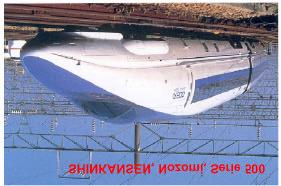
7 Main characteristics - 2 ICE3 ETR500 7
8 Basic requirements 8
9 Basic requirements Commercial. Technical and security. Operation and maintenance. Compatibility with the infrastructures. 9
10 Commercial requirements 10
11 Commercial requirements - 1 Journey time. Number of commercial classes. Number of seats and layout. Types of seats: rotating seats, reclining seats, etc. Level of service for disabled passengers. On-board catering services. Buffet car equipment. Features of the air-conditioning equipment. Level of on-board entertainment: audio-video, Internet, etc. Level of customer service. Other aspects: luggage registration, goods zone, public telephones, nursery, shoe cleaning machines, etc. 11
12 Commercial requirements - 2 Catering area Club car Meeting room Disabled passengers Business cars Tourist cars Cafe-bar Catering area Buffet car Luggage room AVE - S/103 layout 12
13 Technical and security requirements 13
14 Technical and security requirements - 1 Compliance with UIC standards. Compliance with TSI (Technical Specifications for Interoperability). Compliance with railway EN standards. Compliance with national standards. 14
15 Technical and security requirements

16 Technical and security requirements
17 Operation and maintenance requirements 17
18 Operation and maintenance requirements Compliance with reliability standards. Compliance with availability standards. Compliance with standards of cleanliness and comfort. Good maintainability (Getting of the appropriate level of ease of maintenance). 18
19 Compatibility with the infrastructure 19
20 Compatibility with the infrastructure - 1 Compliance with the gauge. Compatibility with the track: respecting wheel/rail forces. Respecting the minimum curve radius of workshops. Compatibility between the access doors and the platforms. Voltage and frequency of the power station. Compatibility with the catenary: height, zigzag and forces. In-cab signalling systems: ETCS, LZB, TVM, ASFA, etc. Respecting the level of harmonics and compliance with the electromagnetic compatibility standards. 20

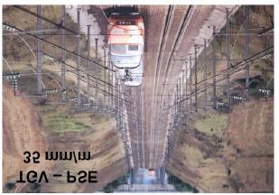

21 Compatibility with the infrastructure - 2 DB - line LZB wire AVE M- Sev mm/m AVE M- Bar mm/m 21
22 Types of trains 22
23 Types of trains Concentrated traction, with one or two end power heads. Distributed traction, with the technical equiments under the carbodies. Conventional train, with two bogies per car. Articulated train, with bogies shared between every two cars. Tilting trains, with active and natural systems. Variable gauge trains. 23
24 Concentrated/distributed traction 24
25 Concentrated/distributed traction - 1 Advantages of distributed traction: Higher passenger capacity for a train fixed length. Reduced axle load, more evenly distributed along the train. Higher number of drive axles: higher acceleration and better adhesion. Possibility of installing a higher traction power. Drawback: Lower performance in cross wind conditions. 25


26 Concentrated/distributed traction - 2 Distributed traction Concentrated traction 26
27 Concentrated/distributed traction - 3 ICE 2, Power head Traction Converter 3 MVA Traction Motor 1.2 MW ICE 3, 4- car subunit Main Transformer 5.22 MVA End car Transformer car Converter car Trailer car Traction motor 0.5 MW Traction converter 2.3 MVA Transformer 4.6 MVA Traction converter 2.3 MVA 27
28 Articulated/non-articulated trains 28
29 Articulated/non articulated trains - 1 Advantages of articulated trains: The intermediate trailer bogies are not under the passengers. More comfortable journeys with less noise. No transversal movement between cars. Passengers can move along the train more easily. The height of the floor can be lowered, resulting in easier passenger access. Experience indicates good performance in case of derailment (more rigid joint between cars). 29

30 Articulated/non articulated trains - 2 Articulated train Non articulated train 30
31 Tilting trains 31
32 Tilting trains - 1 Advantage of tilting trains: Shorter journey times due to the ability to reach higher speed in curves. Drawbacks: More stress on the tracks in curves. Feelings of nausea experienced by a small percentage of passengers. 32


33 Tilting trains - 2 Active tilting Natural tilting 33
34 Variable gauge trains 34
35 Variable gauge trains - 1 Advantages of variable gauge trains: Shorter journey times, because of wheel distance can be changed without stopping. Better passenger comfort, because of train changes are not necessary. Drawbacks: Higher maintenance costs. Little experience of running with motor vehicles. 35


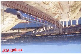
36 Variable gauge trains - 2 AVE - S/130 AVE - S/120 Talgo200 + Locomotive S/252 36
37 Technological challenges of High Speed 37
38 Technological challenges of High Speed The layout of the new High Speed lines. Wheel/rail contact. Mechanical design. Pantograph/catenary contact. Aerodynamic effects. Braking. Traction. Control circuits. Diagnosis system. Speed control (signalling). 38
39 Layout of the new High Speed lines 39
40 Layout of the new High Speed lines - 1 Very high curve radii, > 4000 m. High radius transition curves. Maximum gradients: the new lines, for passenger use only, allow for very high ramps. Direct tracks through the Stations (no platforms near direct tracks). No level crossings. Large section tunnels. 40


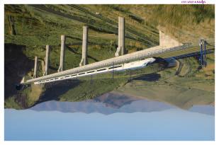
41 Layout of the new High Speed lines - 2: Line profile. Madrid - Barcelona HST line 41
42 Wheel/rail contact Mechanical design 42
43 Wheel/rail contact - 1 A primary challenge. High Speed would not be possible without good running stability. Basically, the objective is to comply with the UIC-518 leaflet: Safety: Prud homme limit, derailment coefficient, instability criteria. Track fatigue: maximum vertical force and lateral and vertical quasi-static forces in curves. Running quality: lateral and vertical accelerations. 43
44 Wheel/rail contact - 2 Wheel/rail stress depends on: The train speed. The characteristics of the track. The characteristics and the state of the rolling stock. The increase in stress with speed is solved by a better quality of track and of bogie design, and also, by appropriate maintenance. 44
45 Wheel/rail contact - 3: Mechanical design Reduced axle load. Light trains with evenly distributed axle loads (maximum 17,68 t/axle). Reduced non-suspended mass (the most aggressive). Hollow axles. Reduced semi-suspended mass. Traction motors under the carbody. Bogies with a big wheel-base (big bogie pitch). Appropriate primary elasticities, wheel profiles and anti-yaw dampers, are necessary to get a good running stability. Concentration of mass in the centre of the bogie. Pneumatic secondary suspension is desirable for comfort. 45

46 Wheel/rail contact - 4: Mechanical design AVE S/100 46

47 Wheel/rail contact - 5 Wheel forces and motions A Wheel profile, with low conicity, is necessary to get a good running stability. 47
48 Pantograph/catenary contact 48
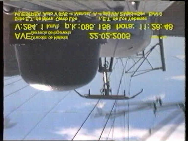
49 Pantograph/catenary contact - 1 As the speed increases, the pantograph/catenary contact deteriorates. This deterioration manifests itself by sparks due to low pantograph contact force and by excessive elevation of the contact wire (excessive contact force). There are two criteria to measure the quality of the pantograph/catenary contact: Measuring the contact force, checking that it remains within optimal values. Measuring the sparks produced during the current collection. 49
50 Pantograph/catenary contact
51 Pantograph/catenary contact - 3 There are several ways of improving the pantograph /catenary contact: Constant height of the contact wire. Catenaries with uniform vertical elasticity, to avoid "hard points" in the poles and "soft points" in the centre of two poles. Increase the mechanical stress of the contact wire. Pantograph with reduced mass, especially at the head, to minimise dynamic forces. 25 kv electrification enables the use of lighter heads. Reduce the number of raised pantographs, introducing a highvoltage line on the roof of the train. Regulate the vertical aerodynamic force by means of active devices or ailerons. Catenaries with automatic temperature compensation. 51
52 Aerodynamic effects 52
53 Aerodynamic effects - 1 Good aerodynamic design is essential to High Speed trains. It can reduce resistance to forward motion, and thereby reduce the train power and the energy consumption. Good car design is needed to reduce the pressure variation for passengers in tunnels: Doors with inflatable joints. Automatic closure of air-conditioning vents. Airtight compartments. Creation of excess pressure inside the train. 53
54 Aerodynamic effects - 2 Two new aerodynamic problems arise when operating at very high speeds >300km/h: The problem of speed limitation in relation to cross winds. The balast pick-up at high speed. These two phenomena are some of the problems that could limit operating speed. 54

55 Aerodynamic effects - 3 A long nose helps against the negative aerodynamic effects. AVE S/102 55
56 Braking 56
57 Braking - 1 The large quantity of kinetic energy to be eliminated in High Speed trains requires a complete re-thinking of classic braking systems. The conventional shoe/wheel system cannot be used for speeds of above 160 km/h, due to the high temperature reached which seriously damages the wheels. Braking at High Speed is effected by the joint automatic action of all the fitted brake systems. Electro-pneumatic controls. 57
58 Braking - 2 Electric brakes: Preferably mixed: regenerative and rheostatic (priority regenerative action). Must be independent of the existence of voltage in the catenary. Automatic action with the pneumatic brake ( blending ). 58
59 Pneumatic brakes: Braking - 3 Preferably with disks (far better thermal cooling than with shoes/wheel). TGV 4 disks/trailer axle 4 shoe/wheel brake blocks, in motor axle AVE S/102 Power heads: 1 disk/axle and 2 semi-disks/wheel Cars: 2 semi-disks/wheel and 1 disk/wheel ICE3 Drive axles: 2 semi-disks/wheel Trailer axles 3 disks/axle 59


60 Braking disks/trailer axle 1 disk/axle and 2 semi-disks/wheel AVE S/100 AVE S/102 60
61 Braking - 5 Other braking systems used are: Induction brake (Foucault or Eddy-current). Electromagnetic shoe. Advantages: Shorter stopping distance. Drawbacks: Problems with the infrastructure: Track erosion, harmonic interferences, etc. 61
62 Traction 62
63 Traction - 1: Train Power Rated power: triple/quadruple that of classic trains. For reasons of reliability, it is also essential to have high power available as a precaution against breakdowns. Three-phase traction is possible for the development of power electronics. Lighter, more powerful and reduced-size traction motors. Several independent groups can easily be installed. Optimal electrification system 25 kv, 50 Hz. 63
64 Traction - 2: Power inverters Constant current inverter Constant voltage inverter L M C M Equal to: switch SCR-thyristor GTO-thyristor IGBT SCR : Silicon Controlled Rectifier GTO = Gate Turn-Off IGBT = Isolated Gate Bipolar Transistor 64
65 Traction - 3: Configurations DC DC Input filter L C Chopper = = Variable voltage L (a) Inverter = ~ Variable frequency M Input filter L C Chopper = = Constant voltage C (b) Inverter = ~ Variable voltage and frecuency M AC AC Transformer Rectifier ~ DC-Link Inverter = = ~ M Transformer Rectifier ~ DC-Link C Inverter = = ~ M Variable voltage (c) Variable frequency Constant voltage (d) Variable Variable voltage voltage and frecuency and frequency 65
66 Traction - 4: Power supply diagram (Bogie1) 25 kv ~ 3 kv = CB ~ Transformer Auxiliary rectifying bridge ~ =? = 1? = 1 CB = ~ ~ = = Main filter Power rectifying bridge 1 BR1 Power rectifying bridge 2 T T = Main chopper = = B B Auxiliary chopper Auxiliary filter = = LFSM ST.C ST.C Inverter 1 = T ~ = ~ Inverter 2 BR2 N SM1 Exc.1 Exc.2 SM2 N = = Auxiliary services Excitation chopper Battery 66
67 Traction - 5: Power supply diagram (Bogie1) CB 25 kv ~ Input converters Auxiliary Converter = 4QS1 = Auxiliary services PWM1 ASM 4QS1 Intermediate circuit DC-Link Transformer 4QS2 Lsk C BR Inverters Csk 4QS3 PWM2 ASM 67

68 Traction - 6: GTO Phase Module (Water Cooling) GTO-Thyristor: 4,5 kv / 3 ka or 4 ka Module dimensions (W x H x D): 450 mm x 415 mm x 312 mm Weight: 70 kg Max. DC link voltage: 2,8 kv Max. rms current: 1,5 ka rms Switching frequency: 350 Hz Water temperature (inlet): 55 C 68
69 Traction - 7: ICE3 Multi-System Traction Container Semiconductor devices: GTO: 4.5 kv, 3.0 ka Container dimensions (W x D x H): 3400 mm x 2200 mm x 450 mm Weight (without cooling equipment): 2,7 t Rated output power: 2,2 MW (AC line voltage only) Line voltages: AC: 15 kv, 16.7 Hz; AC 25 kv, 50 Hz DC: 1.5 kv; 3 kv 69
70 300 F [kn] Traction - 8: ICE3 Tractive and Braking Effort - Speed 6000 kw 40 o /oo o 5 / oo Pwheel = 8000 kw (AC 15 kv 16,7 Hz) (AC 25 kv 50 Hz) 75% redundancy plain v [kph] B [kn] kw AC - Operation 70
71 Traction - 9: Self-propelled trains Self-propelled trains, preferably with "distributed traction" have the following advantages: Reduced axle load that moreover can be evenly distributed along the train. Higher number of drive axles: higher acceleration capacity and the possibility of climbing big gradients. Possibility of using the electric brake as the main brake (braking on many axles). Possibility of modular and flexible design. Possibility to install a higher power supply. Higher passenger capacity for a fixed length of train. 71
72 Control circuits. Diagnosis system 72
73 The control circuits - 1 The control circuits are the vital part of a High Speed train. They consist of computers connected between them (network along the train). All the train equipments are connected to the computer network. By means of the control circuits the driver and crew give orders to the train. The control circuits are redundant. Normally a control circuit takes the train control (master) and the other is in stand-by (slave). In case of a fail of the master controller, the slave takes automatically the control and pass to work as master. 73

74 The control circuits - 2: Power head diagram Locomotive S/252 74

75 The control circuits - 3: Computer network AVE S/102 75
76 The control circuits - 4: Equipments connected to the train computer network Traction equipments. Braking and anti-skid equipments. Auxiliary service equipments. Signalling and communication systems. Juridical recorders. Bogie instability detectors. Temperature detectors in axle boxes. Fire detectors. Passenger information systems. Other equipments: air-conditioning, door controls, lighting, etc. Diagnosis systems, to transmit incidents to the maintenance centre. 76
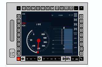
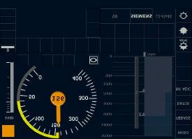
77 The control circuits - 5: Diagnosis system High Speed trains have a diagnosis system to identify breakdowns on board. The diagnostic system automatically sends to the workshop a series of data via GSM digital telephone: Information generated by the train. Information entered by the driver and/or the train crew. Maintenance operations are planned on the basis of the above information. 77


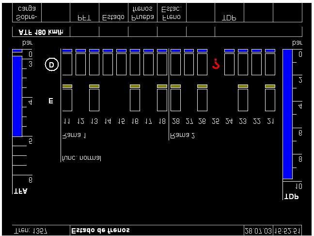
78 The control circuits - 6: Diagnosis system DMI information AVE S/103 78
79 Speed control (signalling) 79
80 Speed control (signalling) - 1 The classic system of vertical signals is not valid at High Speed. Signalling at High Speed has to fulfil the following requirements: In-cab signalling: real speed, permitted speed, target speed, distance to go. Continuous transmission of information is desirable. Automatic breaking action, if the permitted speed is exceeded. 80
81 Speed control (signalling) - 2 Existing systems: ATC (Shinkansen) TVM (TGV), LZB (ICE and AVE-Seville), etc. In Europe, this diversity has presented a considerable difficulty to the interoperability. That it will overcome with the new European ETCS system. 81

82 Speed control (signalling) - 3 ETCS - S/102 ETCS - S/100 82
83 Summary: Basic concepts of High Speed 83
84 Basic concepts of High Speed - 1 High Speed begins at around 250 km/h. Speeds of between 250 km/h and 300km/h require curve radii of > 4.000m and therefore new lines and very important investments. New mixed-traffic lines: 1.25 % grade. Passenger traffic only: 3.5% grade (lower construction costs). Aerodynamic phenomena require a larger separation between tracks (>= 4.50 m) and larger tunnel sections (>= 75 m ), (higher construction costs). High-radius for curves and vertical transitions (variations limited for comfort). Direct tracks through the Stations (no platforms near direct tracks). No level crossings. 84
85 Basic concepts of High Speed - 2 The environmental impact and energy consumption are much lower than for other systems of transport. The interfaces between train and infrastructure, pose fundamental technical questions. The wheel/rail force has to remain within acceptable limits, despite the higher speed. This requires a track of excellent quality and bogies with high running stability. The axle load must be reduced (< 17,68 t/axle). The height of the catenary contact wire must be constant. The elasticity of the catenary must be uniform and the mass of the pantograph reduced. 85
86 Basic concepts of High Speed - 3 The traction power of trains increases with the cube of speed. This requires electric traction and the electrification system, and 25 kv -50 Hz is desirable. The trains are self-propelled and bi-directional. Trains are designed with ultra-aerodynamic profiles to reduce resistance to forward motion and power consumption. Acceleration distances are high, approx. 20 km for 320 km/h. Running at constant speed is a necessity (good average speed and energy savings). Stopping distances increase with speed, almost 4 km at 300km/h. Energy eliminated during braking is very high, and increases with the square of speed. Electric braking and brake disks are necessary. 86
87 Basic concepts of High Speed - 4 Continuous in-cab signalling is essential. The European system for the near future will be the ETCS. The excellent quality of the High Speed services creates new "induced traffic". For distances of between 200 and 1000 km and with high traffic density, there is no doubt that the future of railways lies in High Speed. 87
88 My personal data José A. Jiménez Director de Material Renfe-Alta Velocidad Estación Puerta de Atocha Plaza del Emperador Carlos V, Madrid SPAIN Tel: Fax: jajimenez@renfe.es 88
89 Many thanks for your attention 89
The AGV, a cutting-edge technology integrator
 The AGV, a cutting-edge technology integrator INNOTRANS-BERLIN September 2008 TRANSPORT AGV The Concept INNOTRANS Berlin September 2008- P 2 The AGV concept Build on the TGV s benefits Articulated train
Special edition paper
 Efforts for Greater Ride Comfort Koji Asano* Yasushi Kajitani* Aiming to improve of ride comfort, we have worked to overcome issues increasing Shinkansen speed including control of vertical and lateral
Electrification and Power Supply. Andrea Nardinocchi Technological Design Department Italferr S.p.A., Rome, Italy
 Electrification and Power Supply Andrea Nardinocchi Technological Design Department Italferr S.p.A., Rome, Italy 1 RAILWAY POWER SUPPLY Electrification systems in Europe Electrification design criteria
28/09/2006. ALSTOM Transport. The TGV trainsets
 28/09/2006 ALSTOM Transport The TGV trainsets GENERAL PRESENTATION TGV 1N / TGV 2N FUTURE DEVELOPMENTS OF THE TGV 2N GENERAL PRESENTATION The TGV concept Advantages of the articulation Adaptability for
Traction Systems GC01DTR01_C 08/2013. Ingeteam Traction
 Traction Systems GC01DTR01_C 08/2013 Ingeteam Traction traction@ingeteam.com Vehicle control unit (VCU) Human machine interface (HMI) Traction converter Auxiliary converter INGETEAM Traction designs and
Regional and Suburban Transport
 Regional and Suburban Transport Autorail Grande Capacité France On behalf of the French Regions, the SNCF ordered 500 Autorails Grande Capacité (AGC) for suburban, regional or interregional services. The
JR EAST, a passenger railway company, is the largest railway company in JAPAN
 JR EAST, a passenger railway company, is the largest railway company in JAPAN Network: 7,512.6km No. of Passengers: 16.8 million/day No. of Trains: 12,784/day No. of Employees: 59,370 No. of Rolling stock:
SIMPACK User Meeting May 2011 in Salzburg
 Modular vehicle concept modular model design reliable calculation chain Dynamic analysis of the Avenio platform with multi-body simulation (MBS) Page 1 May 2011 Structure Presentation of Avenio tram platform
The DLR Project Next Generation Train (NGT)
") > UIC Energy Efficiency Workshop, Rome > Holger Dittus The DLR Project Next Generation Train (NGT) > 04/10/2017 DLR.de Chart 1 The DLR Project Next Generation Train (NGT) Holger Dittus UIC Energy Efficiency
> UIC Energy Efficiency Workshop, Rome > Holger Dittus The DLR Project Next Generation Train (NGT) > 04/10/2017 DLR.de Chart 1 The DLR Project Next Generation Train (NGT) Holger Dittus UIC Energy Efficiency
Rail Systems and Rail Vehicles
 Rail Systems and Rail Vehicles Part 1: Rail Systems by Evert Andersson, Mats Berg, Sebastian Stichel, Carlos Casanueva Stockholm 2016 ISBN 978-91-7595-922-1 KTH RAILWAY GROUP Centre for Research and Education
Emerging Technologies for new generation EMUs
 Emerging Technologies for new generation EMUs Technology for new generation AC/DC EMUs in Mumbai Page 1 Septermber 2008 Industry Sector, Mobility Division What is an EMU? It is an Electrical Multiple Unit
HST/VHST Products. October 2006
 HST/VHST Products October 2006 HST/VHST Market Segments Commercial Speed (Km/h) 350 Very High Speed (VHST) 250 High Speed (HST) 200 200 300 400 500 600 Seats per train HST Products October 2006 HST & Tilting
Gröna Tåget. (Eng: Green Train) Overview and Technical Aspects
 Overview and Technical Aspects") Gröna Tåget (Eng: Green Train) Overview and Technical Aspects Evert Andersson, professor Programme coordinator - Technology everta@kth.se evertan@telia.com Background Current Swedish 12-year plan (2004-2015)
Gröna Tåget (Eng: Green Train) Overview and Technical Aspects Evert Andersson, professor Programme coordinator - Technology everta@kth.se evertan@telia.com Background Current Swedish 12-year plan (2004-2015)
High Speed S&C Design and Maintenance
 High Speed S&C Design and Maintenance Dr Sin Sin Hsu Head of Track Engineering, NRHS 1 st March 2018 What is a High Speed Turnout? Three main parts: Switch Geometry, profile, components Intermediate Part
(Non-legislative acts) DECISIONS
 DECISIONS") 14.5.2011 Official Journal of the European Union L 126/1 II (Non-legislative acts) DECISIONS COMMISSION DECISION of 26 April 2011 concerning a technical specification for interoperability relating to the
14.5.2011 Official Journal of the European Union L 126/1 II (Non-legislative acts) DECISIONS COMMISSION DECISION of 26 April 2011 concerning a technical specification for interoperability relating to the
Eurailspeed Parallel Session D.3. Julen Barrutia Commercial Director for Europe, CAF
 Eurailspeed Parallel Session D.3 Julen Barrutia Commercial Director for Europe, CAF High Speed in the technological development of CAF CONSTRUCCIONES Y AUXILIAR DE FERROCARRILES, S.A. EurailSpeed 2005
ALSTOM High Speed Trains: State of the art & perspectives
 ALSTOM High Speed Trains: State of the art & perspectives SVP RSC Product Strategy and Mainline & Locomotive Platform, ALSTOM Transport, France July 12 th 2012, Session: Rolling stock 2 Unmatched experience
Railway Engineering: Track and Train Interaction COURSE SYLLABUS
 COURSE SYLLABUS Week 1: Vehicle-Track Interaction When a railway vehicle passes over a track, the interaction between the two yields forces on both vehicle and track. What is the nature of these forces,
English version of. Executive Order on vehicles' technical compatibility with the rail network (Bekendtgørelse nr af 30. november 2012) Preface
 Preface") English version of Executive Order on vehicles' technical compatibility with the rail network (Bekendtgørelse nr. 1127 af 30. november 2012) Preface Please note that the English version is for informational
English version of Executive Order on vehicles' technical compatibility with the rail network (Bekendtgørelse nr. 1127 af 30. november 2012) Preface Please note that the English version is for informational
Railway Dynamics Studies at CITEF with SIMPACK
 2003 Railway Dynamics Studies at CITEF with SIMPACK Jenny Paulin citef.jpaulin@etsii.upm.es Berta Suárez citef.bsuarez@etsii.upm.es CITEF UPM Centro de Investigación en Tecnologías Ferroviarias Universidad
Fig.1 Sky-hook damper
 1. Introduction To improve the ride comfort of the Maglev train, control techniques are important. Three control techniques were introduced into the Yamanashi Maglev Test Line vehicle. One method uses
SCHALKE LOCOMOTIVES KEEP YOUR BUSINESS ON TRACK
 SCHALKE LOCOMOTIVES KEEP YOUR BUSINESS ON TRACK The ultimate specialists and uniquely developed to suit exacting customer requirements, these locomotives offer a high power density under extreme conditions
Our 100% low-floor trams, made especially for you. siemens.com/mobility
 Avenio fits your city. Our 100% low-floor trams, made especially for you. siemens.com/mobility Avenio fits your city. Made for where you live. Your city is unique and so are your requirements for public
Double gauge High-Speed. interoperability and scope
 Double gauge High-Speed electric-diesel train: increasing interoperability and scope Victorino PÉREZ FERNÁNDEZ Manager of European Affairs, Renfe, Spain 12/07/2012, Session: Rolling Stock 4 Technical development
Council of the European Union Brussels, 18 July 2014 (OR. en)
") Council of the European Union Brussels, 18 July 2014 (OR. en) 11932/14 ADD 1 TRANS 367 COVER NOTE From: European Commission date of receipt: 9 July 2014 To: General Secretariat of the Council No. Cion
Council of the European Union Brussels, 18 July 2014 (OR. en) 11932/14 ADD 1 TRANS 367 COVER NOTE From: European Commission date of receipt: 9 July 2014 To: General Secretariat of the Council No. Cion
Division Locomotives. Borderless locomotives
 Division Locomotives Borderless locomotives Bombardier is leader in the market of electric locomotives European market share 2005 Average European market share 1997-2003 57% 48% 19% Alstom Bombardier Bombardier
Railway Systems. Class 385 for the International Market
 Railway Systems 1 Class 385 exterior (top) and interior (bottom) 1 Class 385 for the International Market In March 2015, the Hitachi Group won a contract for the provision of 234 Class 385 railcars (46
New Generation of SKODA Trams in European Cities
 New Generation of SKODA Trams in European Cities Actual tramcars products Jiří Vokoun Tram platform product manager Škoda Transportation Trams products New Generation of SKODA Trams in European Cities
RSC-G-004-B Guidelines For The Design Of Section 3 3 ELECTRIC TRACTION SYSTEMS 2
 3 ELECTRIC TRACTION SYSTEMS 2 3.1. SAFE FOR PEOPLE 2 3.1.1. Electric Traction System 2 3.1.2. Protection against unwanted access 2 3.1.3. Fencing 2 3.1.4. On bridges and other structures 2 3.1.5. At level
Experience in the construction of the HS trains and the newest train AGV
 Experience in the construction of the HS trains and the newest train AGV TRANSPORT The Alstom Products Range 1 The High Speed in Alstom TRANSPORT Pendolino and High Speed EMUs An International success
Reliable, economical and safe siemens.com/rail-electrification
 AC Traction Power Supply Reliable, economical and safe siemens.com/rail-electrification More people, new challenges, one solution: Integrated mobility. Demographic change, urbanization and climate change:
Qingdao Zener Electric Co., Ltd
 Traction inverter, Power Supply, Emergency ventilation inverter for Light rail train Qingdao Zener Electric Co., Ltd Part 1 Power Supply for the Overhead Traction Line Introduction Conventional power supply
INTEROPERABILITY UNIT TRANS-EUROPEAN CONVENTIONAL RAIL SYSTEM SUBSYSTEM ENERGY
 INTEROPERABILITY UNIT TRANS-EUROPEAN CONVENTIONAL RAIL SYSTEM SUBSYSTEM ENERGY Reference: IU-ENE-071221-TSI 2.1 Document Type: Version: Title: 2.1 - Draft Technical Specification of Interoperability Preliminary
Vehicle Types and Dynamics Milos N. Mladenovic Assistant Professor Department of Built Environment
 Vehicle Types and Dynamics Milos N. Mladenovic Assistant Professor Department of Built Environment 19.02.2018 Outline Transport modes Vehicle and road design relationship Resistance forces Acceleration
SCHALKE LOCOMOTIVES KEEP YOUR BUSINESS ON TRACK
 SCHALKE LOCOMOTIVES KEEP YOUR BUSINESS ON TRACK Schalke locomotives provide maximum versatility and can be used to perform a variety of tasks in suburban and regional passenger rail transport systems.
Development of the gauge change EMU train system in Japan
 Development of the gauge change EMU train system in Japan 1 2 K. Takao & K. Uruga 1 Technical Development Department, Technology Research Association of Gauge Changing Train, Japan 2 Vehicle Control Technical
POWERTRAIN SOLUTIONS FOR ELECTRIFIED TRUCKS AND BUSES
 POWERTRAIN SOLUTIONS FOR ELECTRIFIED TRUCKS AND BUSES PDiM 2017 (Heimo Schreier) Burak Aliefendioglu Fredrik Haag AVL H. Schreier, B Aliefendioglu, F. Haag PDIM 2017 30 November 2017 1 TRUCK & BUS ELECTRIFICATION
DESIGN AND BUILD A HIGH SPEED RAILWAY: THE FRENCH EXPERIENCE. 29 March Jean-Pierre ORSI Director Europe SYSTRA
 DESIGN AND BUILD A HIGH SPEED RAILWAY: THE FRENCH EXPERIENCE Jean-Pierre ORSI Director Europe SYSTRA 1 Fundamental parameters of the Trans-European high speed railway system. Speed increase on conventional
Railway noise mitigation factsheet 01: Overview of railway noise
 Railway noise mitigation factsheet 01: Overview of railway noise 1.1 Noise sources and indicative noise levels Exterior noise sources on high-speed trains can be broadly categorised as follows and are
Guide for the application of the CR ENE TSI
 European Railway Agency According to Framework Mandate C(2007)3371 final of 13/07/2007 Reference in ERA: ERA/GUI/07-2011/INT Version in ERA: 1.00 Date: 26 August 2011 Document prepared by Document type:
2. Test Centre VUZ Velim Cerhenice
 Testing laboratory locations: 1. Testing Laboratory (Not carrying out the tests) Novodvorská 1698, 142 01 Praha 4 - Braník 2. Test Centre VUZ Velim 281 02 Cerhenice The Laboratory is qualified to update
Special edition paper
 Special edition paper Adoption of Articulated Structure in AC Train Ryohei Shimamune*, Takahiro Kikuchi*, Hiroshi Nomoto* and Mitsuyuki Osawa* The AC Train that is destined to become the next-generation
A Study on the Measurement of Contact Force of Pantograph on High Speed Train
 ICCAS005 June -5, KINTEX, Gyeonggi-Do, Korea A Study on the Measurement of Contact Force of Pantograph on High Speed Train Sung-Il Seo*, Yong-Hyun Cho**, Jin-Yong Mok***, Choon-Soo Park*** and Ki-Hwan
BRIEF ON ELETRICAL MULIPLE UNITS (EMU)
") BRIEF ON ELETRICAL MULIPLE UNITS (EMU) Electrical multiple units are used by Indian railways to carry mass passengers in metro and inter cities. The unit consists of motor coach and multiple trailer coaches.
BRIEF ON ELETRICAL MULIPLE UNITS (EMU) Electrical multiple units are used by Indian railways to carry mass passengers in metro and inter cities. The unit consists of motor coach and multiple trailer coaches.
High speed diesel powered trains: An efficient approach to existing and future diesel freight lines
 High speed diesel powered trains: An efficient approach to existing and future diesel freight lines ABOUT TALGO HIGH SPEED DIESEL TRAINS ELECTRIC AND DIESEL CASE STUDY: SPAIN MIDDLE EAST OVERVIEW CONCLUSIONS
A study of the train performance simulation for Korean next Generation high-speed train. high-speed train.
 Challenge A: A more and more energy efficient railway A study of the train performance simulation for Korean next Generation high-speed train Taehyung LEE, Choonsoo PARK, Sunghoon CHOI, Kihwan KIM High-Speed
Power Assembly Complete Solutions
 Power Assembly Complete Solutions Dynex Semiconductor in Lincoln has 40 years experience in power electronics Dynex Semiconductor (Dynex) is one of the foremost suppliers of power semiconductor components
Regenerative braking and the different traction systems
 Energy Recovery Workshop Madrid, September, 29, 2015 Regenerative braking and the different traction systems Ignacio González and Eduardo Pilo Spanish Railways Foundation Index 1. Introduction 2. Traction
SP2 Requirements toward the freight system of FFE (Madrid Spain) 21 September 2017
 21 September 2017") Capacity for Rail SP2 Requirements toward the freight system of 2030-2050 FFE (Madrid Spain) 21 September 2017 Bo-Lennart NELLDAL Project Leader WP2.1 Content 1. Today s market 2. Demand for rail and freight
Capacity for Rail SP2 Requirements toward the freight system of 2030-2050 FFE (Madrid Spain) 21 September 2017 Bo-Lennart NELLDAL Project Leader WP2.1 Content 1. Today s market 2. Demand for rail and freight
Lecture 2. Power semiconductor devices (Power switches)
") Lecture 2. Power semiconductor devices (Power switches) Power semiconductor switches are the work-horses of power electronics (PE). There are several power semiconductors devices currently involved in
Lecture 2. Power semiconductor devices (Power switches) Power semiconductor switches are the work-horses of power electronics (PE). There are several power semiconductors devices currently involved in
Shinkansen Technology Exportation
 Fast track to Sustainable Mobility Shinkansen Technology Exportation Taiwan High Speed Rail 7T Ministry of Railway of China CRH2 Kwasaki Heavy Industries, Ltd. Rolling Stock Company 18 March 28 1 Taiwan
Simulation of railway track maintenance trains at MATISA
 Simulation of railway track maintenance trains at MATISA MultiBody Simulation User Group Meeting Rémi ALLIOT, Solution Consultant, Dassault Systèmes SE Jacques ZUERCHER, Head of Calculation Department,
- friction and heat free braking of moderately
 22 WIT Press, Ashurst Lodge, Southampton, SO4 7AA, UK. All rights reserved. What type of electric brake is most reasonable? - friction and heat free braking of moderately powered, moderately distributed
Track friendly vehicles - principles, advantages. Sebastian Stichel August 8, 2007
 Track friendly vehicles - principles, advantages Sebastian Stichel August 8, 2007 What is track friendliness A track friendly vehicle is a vehicle that causes low maintenance costs on the track (and on
The track-friendly high-speed bogie developed within Gröna Tåget
 The track-friendly high-speed bogie developed within Gröna Tåget A. Orvnäs 1 (former 2), E. Andersson 2, S. Stichel 2, R. Persson 3 1 Mechanical Systems, Interfleet Technology 2 Division of Rail Vehicles,
POSITION PAPER Version 3.0
 POSITION PAPER Version 3.0 Revision of the Technical Specification for Interoperability / Energy (ENE) Brussels, September 26 th, 2012 1. REFERENCE DOCUMENT UNION RAIL SYSTEM - SUBSYSTEM Energy - TSI Energy
Our mission is. to fulfil the current and future expectations of. domestic and foreign owners of rolling stock. through
 Locomotives Our mission is to fulfil the current and future expectations of domestic and foreign owners of rolling stock through the construction, modernisation and repair of rolling stock and by ensuring
Innovative Power Supply System for Regenerative Trains
 Innovative Power Supply System for Regenerative Trains Takafumi KOSEKI 1, Yuruki OKADA 2, Yuzuru YONEHATA 3, SatoruSONE 4 12 The University of Tokyo, Japan 3 Mitsubishi Electric Corp., Japan 4 Kogakuin
New generation of gauge changeover Facilities: The UNICHANGER Project
 New generation of gauge changeover Facilities: The UNICHANGER Project Dr. I.J. Iglesias High Speed Operations and Engineering Direction. Technical Coordination Director. ADIF. Summary 1. The problem of
Reliable rail traffic from the very first day
 Published by Siemens AG 2016 Mobility Division Siemens Mobility Services Otto-Hahn-Ring 6 81739 Munich Germany Order No. A19100-V910-B116-V1-7600 Printed in Germany ZuZ 16-243 Dispo 21700 c4bs 1425 08161.
siemens.com/mobility-services Published by Siemens AG 2016 Mobility Division Siemens Mobility Services Otto-Hahn-Ring Munich Germany
 Published by Siemens AG 2016 Mobility Division Siemens Mobility Services Otto-Hahn-Ring 6 81739 Munich Germany Order No. A19100-V910-B116-V1-7600 Printed in Germany ZuZ 16-243 Dispo 21700 c4bs 1425 08161.
Electric multiple units
 Electric multiple units Our mission is to fulfil the current and future expectations of domestic and foreign owners of rolling stock through the construction, modernisation and repair of rolling stock
Practical Variable Speed Drives and Power Electronics
 Practical Variable Speed Drives and Power Electronics Malcolm Barnes CPEng, BSc(ElecEng), MSEE, Automated Control Systems, Perth, Australia AMSTERDAM BOSTON HEIDELBERG LONDON. NEW YORK OXFORD PARIS SAN
ALS (Active Lateral Suspension) By Bernard GAUTIER SNCF
 By Bernard GAUTIER SNCF") ALS (Active Lateral Suspension) By Bernard GAUTIER SNCF The vertical and lateral motions of a railway vehicle come from the track and the wheel - rail contact dynamics. The motions of the vehicle determinate
ALS (Active Lateral Suspension) By Bernard GAUTIER SNCF The vertical and lateral motions of a railway vehicle come from the track and the wheel - rail contact dynamics. The motions of the vehicle determinate
Council of the European Union Brussels, 18 July 2014 (OR. en)
") Council of the European Union Brussels, 18 July 2014 (OR. en) 11933/14 ADD 1 TRANS 368 COVER NOTE From: European Commission date of receipt: 9 July 2014 To: General Secretariat of the Council No. Cion
Council of the European Union Brussels, 18 July 2014 (OR. en) 11933/14 ADD 1 TRANS 368 COVER NOTE From: European Commission date of receipt: 9 July 2014 To: General Secretariat of the Council No. Cion
Central Japan Railway Company, Komaki, Japan 1 ; Central Japan Railway Company, Tokyo Japan 2
 Innovative lightweight traction system technologies employing power electronics on the Shinkansen high-speed EMUs - Environmentally-friendly aspect and innovative traction systems - 1 Yoshiyasu HAGIWARA,
Shinkansen- Japanese High Speed Railway Network Shinkansen- Japoński System Kolei Dużych Prędkości. Hitachi Rail Europe
 Shinkansen- Japanese High Speed Railway Network Shinkansen- Japoński System Kolei Dużych Prędkości Hitachi Rail Europe Nick Watson Head of Commercial and Business Planning Contents The Shinkansen Transferability
November 2001 NEW DEVELOPMENTS FOR TILTING TRAINS. Alessandro ELIA Tilting Systems Director
 November 2001 NEW DEVELOMENS FOR LNG RANS Alessandro ELA ilting Systems Director New Developments for tilting trains A view of the prototype 3 kv EM train ER401 V610 DM for DB Railways Goal of endolino
Retrofit traction solutions Selected references
 T R AC T I O N Retrofit traction solutions Selected references 3 Table of contents 004 005 Compact Converter for people mover Port Authority of New York and New Jersey, United States Compact Converter
Electric cars: Technology
 In his lecture, Professor Pavol Bauer explains all about how power is converted between the various power sources and power consumers in an electric vehicle. This is done using power electronic converters.
Application Research on CHR2 Type EMU Braking System
 Vehicle Dynamics (2017) Original Research Article Application Research on CHR2 Type EMU Braking System Lei Pan,Wenjuan Zhang,Lina Chen School of Vehicle and Traffic Engineering, Shaoyang University of
Speech Joern F. Sens CEO I MO Business Unit Rolling Stock. The Rolling Stock Product Portfolio
 Speech Joern F. Sens CEO I MO Business Unit Rolling Stock The Rolling Stock Product Portfolio Ladies and Gentlemen, Allow me to extend a warm welcome to you to the pre-press conference. You have already
Simulation of a Narrow Gauge Vehicle using SIMPACK, Model Validation using Scaled Prototypes on Roller-Rig
 Simulation of a Narrow Gauge Vehicle using SIMPACK, Model Validation using Scaled Prototypes on Roller-Rig Politecnico di Torino Dipartimento di Meccanica N. Bosso, A.Gugliotta, A. Somà Blue Engineering
UNISIG * EEIG ERTMS USERS GROUP * UNIFE
 ERTMS/ETCS REF: VERSION: DATE: 17/12/15 Page 1/18 Modification history Issue number date Draft 27.07.99 Draft 01 30.08.99 0.1.1 24.09.99 1.0.0 11.10.99 1.0.1 31.01.2000 1.0.2 14.02.2000 1.0.3 22.02 1.1.0
Company profile 2 Profile of ČKD ELEKTROTECHNIKA 2
 Applications Table of contents Company profile 2 Profile of ČKD ELEKTROTECHNIKA 2 Applications 3 Power semiconductor units PSU 3 Custom-design PSU 4 PSU wirings 5 GU 3391 control unit for tyristors 6
DRIVETRAIN 7.0 Introduction 7.1 Drivetrain configurations 7.2 Drivetrain elements 7.3 Clutch Operation
 DRIVETRAIN 7.0 Introduction Drivetrain is the assembly of all the components that are involved in the transmission of the power from the engine of the vehicle to its wheels. 7.1 Drivetrain configurations
Electric Machines CHARLES A. GROSS. Aubum University Auburn, Alabama, U.S.A. LßP) CRC Press Vv* / Taylor & Francis Croup. Boca Raton London New York
 CRC Press Vv* / Taylor & Francis Croup. Boca Raton London New York") Electric Machines CHARLES A. GROSS Aubum University Auburn, Alabama, U.S.A. LßP) CRC Press Vv* / Taylor & Francis Croup Boca Raton London New York CRC Press is an imprint of the Taylor & Francis Group,
Electric Machines CHARLES A. GROSS Aubum University Auburn, Alabama, U.S.A. LßP) CRC Press Vv* / Taylor & Francis Croup Boca Raton London New York CRC Press is an imprint of the Taylor & Francis Group,
Evaluation of the Fatigue Life of Aluminum Bogie Structures for the Urban Maglev
 Evaluation of the Fatigue Life of Aluminum Bogie Structures for the Urban Maglev 1 Nam-Jin Lee, 2 Hyung-Suk Han, 3 Sung-Wook Han, 3 Peter J. Gaede, Hyundai Rotem company, Uiwang-City, Korea 1 ; KIMM, Daejeon-City
Standards Manager Web Standards List RSSB-Rail Safety and Standards Board
 Standards Manager Web Standards List RSSB-Rail Safety and Standards Board Id Number Title Year Organization Page GERT80 Iss ERTMS/ETCS DMI National Requirements 06 RSSB 0 GIGN7608 Iss Guidance on the Infrastructure
Automotive Transmissions
 Gisbert Lechner Harald Naunheimer Automotive Transmissions Fundamentals, Selection, Design and Application In Collaboration with Joachim Ryborz With 370 Figures J i Springer Contents Terms and Symbols
Development of Motor-Assisted Hybrid Traction System
 Development of -Assisted Hybrid Traction System 1 H. IHARA, H. KAKINUMA, I. SATO, T. INABA, K. ANADA, 2 M. MORIMOTO, Tetsuya ODA, S. KOBAYASHI, T. ONO, R. KARASAWA Hokkaido Railway Company, Sapporo, Japan
Results in rail research using SIMPACK
 Results in rail research using SIMPACK Politecnico di Torino - Dip. di Meccanica IIa Facoltà di Ingegneria (Vercelli) N. Bosso, A. Gugliotta, A. Somà The railway dynamic research group of the Mechanical
Power Protection Discrete Automation & Motion South Africa
 Carel Oberholzer, ABB South Africa, May 2013 PCS100 Power Protection Discrete Automation & Motion South Africa May 13, 2013 Slide 1 Power Protection Agenda 1. Introduction of power protection 2. Overview
Development of a High Efficiency Induction Motor and the Estimation of Energy Conservation Effect
 PAPER Development of a High Efficiency Induction Motor and the Estimation of Energy Conservation Effect Minoru KONDO Drive Systems Laboratory, Minoru MIYABE Formerly Drive Systems Laboratory, Vehicle Control
Avenio fits your city.
 4 modules m Seats Standing places 2 8 modules m Seats Standing places GB100335 2303 WS 09101.0 Dispo 210 c4bs 7648 Order No.: A19100-V0-B876-X-7600 /avenio P.O. Box 30 910 Erlangen transport. 1 2 2 2 2
WELCOME TO LOCOMOTIVE DESIGN CENTRE RDSO
 WELCOME TO LOCOMOTIVE DESIGN CENTRE RDSO SOFTWARE USED UNIGRAPHICS(NX) TEAM CENTER ANSYS MSC Nastran CAD PDM FEM Fatigue Analysis CAD- COPMUTER AIDED DESIGN PDM- PRODUCT DATA MANAGEMENT HIGH ADHESION
Fast thyristors. When burning for induction heating solutions.
 Fast thyristors. When burning for induction heating solutions. By Ladislav Radvan, ABB s.r.o., Semiconductors. Published by Power Electronics Europe (August 2014) Induction heating is one of the key metal
(Non-legislative acts) DECISIONS
 DECISIONS") 26.5.2011 Official Journal of the European Union L 139/1 II (Non-legislative acts) DECISIONS COMMISSION DECISION of 26 April 2011 concerning a technical specification for interoperability relating to the
26.5.2011 Official Journal of the European Union L 139/1 II (Non-legislative acts) DECISIONS COMMISSION DECISION of 26 April 2011 concerning a technical specification for interoperability relating to the
Development of an actively controlled, acoustically optimised single arm pantograph
 Development of an actively controlled, acoustically optimised single arm pantograph Authors Dr. Wilhelm Baldauf 1), Rene Blaschko 2), Dr. Wolfgang Behr 1), Dr. Christoph Heine 1), Michael Kolbe 1) 1) Deutsche
Power Electronics for Medium Voltage Grid Applications Topologies and Semiconductors
 Grid Applications Topologies and Semiconductors Prof. Dr.-Ing. Marc Hiller ELECTROTECHNICAL INSTITUTE (ETI) KIT The Research University in the Helmholtz Association www.kit.edu The Electrical Drives and
Permissible Track Forces for Railway Vehicles
 British Railways Board Page 1 of 11 Part A Synopsis This document prescribes design and maintenance requirements for traction and rolling stock and for on track plant to ensure that interactive forces
ENERGY SAVING ISSUES IN RAILWAY AUTOMATION
 ENERGY SAVING ISSUES IN RAILWAY AUTOMATION P. Colaneri DEIB, Politecnico di Milano - Italy 1 December 12, 2015 1 Collaboration with Alstom Transport Introduction Figure 1: Comparizon SNCF 2012: Raiway
UIC WORKSHOP ON ENERGY EFFICIENCY OF FUTURE TRAINS
 UIC WORKSHOP ON ENERGY EFFICIENCY OF FUTURE TRAINS Infrastructure for energy efficiency: Innovation technologies towards energy efficiency Rome, 4-10-2017 Claudio Spalvieri RFI Technical Dpt. - Technology
STEADY STATE ELECTRICAL DESIGN, POWER PERFORMANCE AND ECONOMIC MODELING OF OFFSHORE WIND FARMS
 STEADY STATE ELECTRICAL DESIGN, POWER PERFORMANCE AND ECONOMIC MODELING OF OFFSHORE WIND FARMS J.T.G. Pierik 1, M.E.C. Damen 2, P. Bauer 2, S.W.H. de Haan 2 1 Energy research Centre of the Netherlands
TSG15B Pantograph technical document. Pantograph 25 kv TSG15B
 Pantograph 25 kv TSG15B 1 1 Purpose / function The pantograph is articulated machine system, which install in roof of locomomtive with insulators. It maintains the power supply from an overhead line on
SINAMICS SM150. 4/2 Overview. 4/2 Benefits. 4/2 Design. 4/6 Function. 4/8 Selection and ordering data. 4/8 Options
 /2 Overview /2 Benefits /2 Design /6 Function /8 Selection and ordering data /8 Options Technical data /1 General technical data /15 Control properties /15 Ambient conditions /16 Installation conditions
Sicat SR. Features. Overhead conductor rail system for mass transit and main-line railways. siemens.com/rail-electrification
 Sicat SR Overhead conductor rail system for mass transit and main-line railways siemens.com/rail-electrification Urban mass transit systems, such as metros and city trains, and even main-line railways
Design Calculation and Verification using SIMPACK Wheel/Rail
 Design Calculation and Verification using SIMPACK Wheel/Rail Bombardier Transportation, Site Winterthur Business Unit Bogies Competent for Single Axle Running Gears Bogies for Regional Trains Bogies for
GEX16/18/20s. Electric Four-Wheel Forklifts 48V, AC Drive Super Elastic Tyres kg kg kg.
 GEX16/18/20s Electric Four-Wheel Forklifts 48V, AC Drive Super Elastic Tyres 1.600 1.800 2.000 www.clarkmheu.com DIMENSIONS GEX16/18/20s 4.35 Wa 4.36 b 13 4.21 b 1 l 6 A st = Wa + x + l 6 + a gilt nur
Truck Trolley System Siemens AG 2014
 Truck Trolley System Empfohlen wird auf dem Titel der Einsatz eines vollflächigen Hintergrundbildes (Format: 25,4 x 19,05 cm): Albrecht Bild auf Brodkorb Master platzieren (JPG, RGB, 144dpi) 26.8.2014