1/8 scale Wedell-Williams Model 44 ARF
|
|
|
- Jean Atkinson
- 5 years ago
- Views:
Transcription
: 40 in. (1016mm) 31 in. (787mm) 325 in². (20.97dm²) 29.7 oz. (842g) 35.0 oz.")
1 1/8 scale Wedell-Williams Model 44 ARF Wingspan: Length: Wing Area: Weight (w/o battery): Weight (w/ PQ1800-3S): 40 in. (1016mm) 31 in. (787mm) 325 in². (20.97dm²) 29.7 oz. (842g) 35.0 oz. (992g) 1
2 2


3 Pilot-1 is pleased to announce the 1/8 scale Wedell-Williams Model 44 Racer as part of the Golden Age Civilian Series. The Pilot-1 Model 44 encompasses the same attributes in quality construction and handling that made the original Wedell-Williams a winning design. In fact, the Wedell-Williams design won more overall races between 1931 and 1936 than any other race plane. From 1932 to 1935, a model 44 won 1 st, 2 nd, 3 rd against the Gee Bee R-1 and Gee Bee R-2, which by the way placed last. Our engineers have spent countless hours developing a true-to-scale ARF that looks and flies like the full-scale Model 44. There are few airplanes that fly slow like an Aeronca Champ AND fly fast wingtip-to-wingtip with the famous Gee Bee racers. We know you will be pleased with the Model 44. With its beautiful looks, balanced maneuverability, and docile flying characteristics, it is a design that is truly at home in the Winner s Circle! Hobby Lobby International, Inc Franklin Pike Circle Brentwood, TN WE-FLY-RC ( ) 3
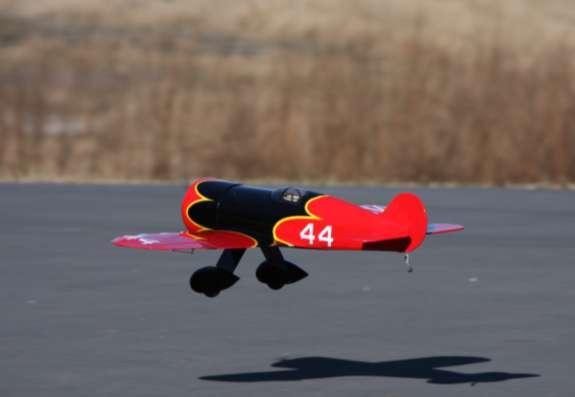
![History The Wedell-Williams Model 44 [and in our case, also Race #44 ] was a racing aircraft, four examples of which were built in the United States in the early 1930s.](/docs-images/94/122311943/images/4-0.jpg "It began as a rebuilding of the partnership's successful We-Will racer of 1929, but soon turned into a completely new aircraft.")
4 History The Wedell-Williams Model 44 [and in our case, also Race #44 ] was a racing aircraft, four examples of which were built in the United States in the early 1930s. It began as a rebuilding of the partnership's successful We-Will racer of 1929, but soon turned into a completely new aircraft. It was a typical 1930s racer design, a braced, low-wing monoplane powered by a large radial engine and equipped with fixed landing gear in large spats. Model 44s were raced in the 1932, 33, and 34 Bendix Trophy races, as well as the 1934 Thompson and Shell Trophy. In September, 1933 at the International Air Race in Chicago the 44 piloted by Jimmie Wedell set the new world speed record of miles per hour. Specifications (Wedell-Williams Model 44) Crew: One pilot Length: 24 ft 6 in (7.47 m) Wingspan: 26 ft 0 in (7.93 m) Empty weight: 2,492 lb (1,133 kg) Loaded weight: 3,892 lb (1,769 kg) Powerplant: 1 Pratt & Whitney R-1690, 1,020 hp (760 kw) Performance Maximum speed: mph (472 km/h) Range: 900 miles (km) Service ceiling 14,000 ft (m) Power/mass: 0.26 hp/lb (0.43 kw/kg) (Source: Wikipedia, 12/11/2008) For more information, go to the web and search Wedell Williams Model 44 or use these links:
 Contents List Fuselage Battery Hatch Engine Cowl Landing Gear and Gear Leg Covers Wheel Pants Wheels, Velcro, Tailwheel, Misc Hardware Canopy Wings and")
 (4) Hitec HS-55 Servos 18 amp Jeti Advance Plus Brushless ESC AXI 2217/16 Brushless Motor AXI 22 Series Radial Mount APC 10x7 E Propeller Soldering Iron and Electrical")
5 Before starting, use the Contents list to take an inventory and make sure it is complete. If any parts are missing or are not of acceptable quality, contact Hobby-Lobby.com Support at WE-FLY-RC ( ) Contents List Fuselage Battery Hatch Engine Cowl Landing Gear and Gear Leg Covers Wheel Pants Wheels, Velcro, Tailwheel, Misc Hardware Canopy Wings and Ailerons Tube Wing Joiner Horizontal Tail Vertical Tail Pushrods Additional Items Required 4-channel Aircraft Radio w/ Receiver (minimum) 1800 mah, 3-cell, 11.1v Lipo Battery ( mah) (4) Hitec HS-55 Servos 18 amp Jeti Advance Plus Brushless ESC AXI 2217/16 Brushless Motor AXI 22 Series Radial Mount APC 10x7 E Propeller Soldering Iron and Electrical Solder 5-minute Epoxy Glue and Canopy Glue Thin CA Glue Small Phillips Screwdriver Needle Nose Pliers Hobby Knife 5


6 1. These instructions are written for someone who has assembled at least one or two planes. It is very easy to assemble. However, if you need help, contact a local model airplane flyer or contact us here at Hobby-Lobby.com. Carefully follow each step in the order they appear in this manual. It should take 4 to 6 hours. So, let s get started! 2. Start by removing the ailerons and CA hinges from the wing. They should not be glued in place from the factory. 3. Prepare CA hinges for installation as shown. When bending the hinges in half, take careful note of the direction of precut slots. You will need to bend the hinges back and forth several times to loosen them up. 4. Insert the bent CA hinges in the aileron precut slots. Use a hobby knife if slots are too tight or not deep enough. 6


7 5. Insert the aileron CA hinges into the wing. The pre-bend in the hinge should allow you to keep hinge 50% in the wing and 50% in the aileron. 6. Use thin CA to glue hinges in place. Make sure there is an even gap on each end of the aileron. The aileron is deflected slightly during gluing. Use 2 to 3 drops of thin CA per hinge, per side. Note the tight fit between the aileron and the wing. 7. Depending on the type of servos you are using, you may need to trim the balsa blocks as shown. 8. Turn on radio. Make sure the aileron trim is centered and all programming is reset to neutral. Install servo arm 90º to the plate and located in the center of slot. Install the servo screws into the balsa blocks. 7
 diameter.")


8 9. Trim the opposite horn flush. Drill the outer servo arm hole out to 3/64 (1.2mm) diameter. This hole is located 1/2 (13mm) from the center of the servo screw 10. Use tape to secure pull-string and the 12 servo extension wire. Pull servo wire through wing. 11. Install aileron horn into aileron hole. Use a hobby knife to remove covering material from under the horn. Then install control horn in place and glue with thin CA. Drill out middle hole in horn with 3/64 (1.2mm) drill, or use hobby knife point to enlarge hole. Install aileron pushrod as shown. 12. Install four short sheet metal screws to hold cover in place. Repeat for opposite wing. 8


9 13. Insert the Elevator into slot in the fuselage. 14. Now, insert horizontal stabilizer into slot as shown. 15. Align horizontal stabilizer so that holes for vertical stabilizer are perfectly aligned. We will glue the entire tail in a later step, so do NOT glue just yet. 16. Insert vertical stabilizer into fuselage as shown. Again, do NOT glue.. 9


10 17. The Hobby-Lobby.com R&D department has determined that the CA hinges for the Elevator and Rudder are too stiff as supplied in the kit. We recommend that you cut away 2/3 of each hinge as shown. Take care to cut along the precut slits in the hinge. There is still plenty of strength left in the hinge for a model this size. You will use four (4) small CA hinges on the Elevator and two (2) on the Rudder 18. Insert CA hinge into elevator and horizontal stabilizer. You will have to flex elevator just a little bit. The x shows the portion of each CA hinge to trim away. 19. Use thin CA to glue hinges in place. Use 2-3 drops per hinge 20. Use thin CA to glue the Vertical and horizontal stabilizer in place. Be very careful with application. A super thin applicator tip on your CA bottle will help with this step. Use CA debonder on paper towel to clean up any CA drips. 21. Remove covering from bottom of Rudder as shown. Also install the Rudder control horn and center it in rudder. Use thin CA to glue it in place. 10


11 22. Insert tailwheel into the predrilled hole in the rudder. No glue is necessary. 23. Insert the trimmed CA hinges in Rudder and install as shown. Use 2-3 drops of thin CA to secure hinges in place. 24. Attach tailwheel bracket to fuselage with two (2) sheet metal screws. Align tailwheel with Rudder and tighten set screw as shown. 25. Install the servos as shown. Turn on radio. Make sure the Elevator and Rudder trims are centered and all programming is reset to neutral. 11


12 26. Assemble the ends of the rudder pull-pull cables as shown. Make sure to double loop the cable through the crimp and compress crimp with needle nose pliers. Attach the left rudder cable to the right control arm and vice-versa. The cables inside the fuselage should cross each other once and make an X. 27. Insert the elevator pushrod into the left pushrod tube. Install the servo horn onto the z-bend and then onto the servo. Do not forget to install the servo screw. Trim the opposite side of the horn with pliers as shown. 28. Align horn with elevator pushrod and insert horn points through elevator. Remove covering around horn. Insert horn into elevator and glue with thin CA. 29. Use fine permanent marker to mark music wire adjacent to control horn holes. This is where you will make a 90-degree bend in the wire. Do NOT bend wire quite yet. 12


13 30. Insert the Elevator pushrod standoff T and the plastic clevis retainer clip as shown. 31. Use needle nose pliers to bend elevator pushrod 90degrees toward horn. Install plastic clevis retainer as shown. 32. Position elevator pushrod support T as shown. Make sure the pushrod is straight. While holding fuselage upside down, use 5- min epoxy to glue support T to covering. *Note: Be very careful here. Do not to glue the rudder cable! 33. Temporarily hold rudder in the center position. Here we have use wooden dowel scraps and a rubber band. The idea is to keep rudder centered while we adjust the rudder pull-pull cables. 13


14 34. Assemble the rudder pull-pull cable as shown. Make sure the radio is on and all trims are centered. Lightly pull slack out of cable 35. Compress cable crimp with needle nose pliers. Repeat for opposite side. Remove the temporary brace on the rudder. 36. Remove the forward tailwheel bracket screw. Use a crimp tube to make a loop in the end of the cable and compress with needle nose pliers. Insert screw through wire loop and reinstall as shown. 37. Feed wire cable through predrilled holes in horizontal and vertical tail as shown. 14


15 38. Using a wire crimp, route a wire loop around the forward tailwheel bracket screw as shown. Use needle nose pliers to compress the wire crimp. Cut off excess wire and tighten screw. Note: use thin CA on each crimp tube after compressing with pliers. This also goes for all crimp tubes used in assembly. 39. This photo shows the completed tail brace wire highlighted for emphasis. 40. Insert the landing gear legs into the fuselage slots. 41. Insert the plywood retainer blocks as shown. The notch faces toward the aircraft centerline. 15


16 42. Some light trimming may be needed but the blocks should be flush. Use thin CA to glue blocks in place. 43. Locate the wheel pants, main wheels, and wheel collars. 44. Partially insert the wheel pant onto the landing gear wire leg. Slide the inboard wheel collar onto wire. 45. Install the main wheel and outboard wheel collar. 16


17 46. Insert the end of the landing gear wire into the outboard wheel pant plywood block. 47. Fully slide wheel pant assembly inboard until wire is seated in molded slot. Tighten wheel collar set screws. Use canopy glue to attach landing gear wire end to plywood block as shown. 48. Insert the landing gear cover. Use canopy glue to attach to wheel pant as shown. Use tape to temporarily hold in place while glue dries. 49. Attach landing gear leg covers with two (2) plastic straps and very short sheet metal screws as shown. Plastic Straps 17


 53.")
18 50. Insert Carbon Fiber wing tube into fuselage. Slide each wing panel onto wing tube and feed aileron servo wire into fuselage. Use two (2) small pieces of clear tape on bottom of wing joint per wing panel to hold each wing panel in place. 51. Solder the electronic speed control (ESC) connectors and DEANS Ultra battery connector as shown. 52. Connect the motor and ESC wires together. For AXI motors, connect the Red-to-Red, Black-to-Yellow, and Yellow-to-Black. (Mismatching any two wires will make the motor turn the proper direction for our application.) 53. Install the motor to the motor mount using the motor supplied counter-sunk screws. Make sure to install the aluminum wheel collar on the rear motor shaft as shown. This distributes the prop loads into the rear bearing. 18


19 54. Install the motor onto the firewall with (4) machine screws. 55. Insert the ESC through the nose section and route along right side of plane. 56. Use small tie wraps or tape to secure ESC wires. 57. Fabricate and install a battery guide block out of scrap balsa or foam. Use 5-min epoxy to glue it in place. This will help protect the battery from rubbing against the rear motor shaft and engine mount screws


20 59. Enlarge hole in plastic dummy engine with a dremel tool and ½ sanding drum. You could also carefully use your hobby knife or canopy scissors. 60. Make sure you have at least a 1/8 (5mm) of clearance between the motor and dummy engine. 61. Install cowl, prop, and spinner. It should look like this from the top of the cowl. There should be approximately ½ gap between cowl and propeller. 62. Install battery hatch. 20

 up and 1/2 (12mm) down. Use 40% expo to soften the center travel per your radio manual. (JR/Spektrum +40% and Futaba/Hitec -40%) 12mm 12mm 66.")
21 63. Install canopy with canopy glue and temporarily tape in place while glue dries. The back edge of the canopy should be flush with the battery hatch aft bulkhead. 64. Please refer to your radio manual for the following few steps. Please note that some computer radios have separate settings for exponential for high and low rate positions. Make sure you double check all settings before flight. If you are new to programming, check with a local experienced modeler or hobby shop for assistance. The use of Exponential (expo) is recommended. 65. Adjust Elevator HIGH RATE travel to get 1/2 (12mm) up and 1/2 (12mm) down. Use 40% expo to soften the center travel per your radio manual. (JR/Spektrum +40% and Futaba/Hitec -40%) 12mm 12mm 66. Adjust Elevator LOW RATE travel to get 5/16 (8mm) up and 5/16 (8mm) down travel. Use 30% expo to soften the center travel per your radio manual. (JR/Spektrum +30% and Futaba/Hitec -30%) 8mm 8mm 21
 LEFT and 5/16\" (8mm) RIGHT. Use 20% expo to soften the center travel per your radio manual. (JR/Spektrum +20% and Futaba/Hitec -20%). 8mm 8mm 69.")
 22mm 22mm 70. Adjust each aileron s LOW RATE up and down travel to get 5/8 (16mm) using the end point adjustment.")
22 67. Adjust Rudder HIGH RATE travel to get 1/2 (12mm) left and 1/2" (12mm) right Use 30% expo to soften the center travel per your radio manual. (JR/Spektrum +30% and Futaba/Hitec -30%). 12mm 12mm 68. Adjust Rudder LOW RATE travel to get 5/16 (8mm) LEFT and 5/16" (8mm) RIGHT. Use 20% expo to soften the center travel per your radio manual. (JR/Spektrum +20% and Futaba/Hitec -20%). 8mm 8mm 69. Adjust each aileron s HIGH RATE up and down travel to get 7/8 (22mm) using the end point adjustment. Use 40% expo to soften the center travel per your radio manual. (JR/Spektrum +40% and Futaba/Hitec -40%) 22mm 22mm 70. Adjust each aileron s LOW RATE up and down travel to get 5/8 (16mm) using the end point adjustment. Use 30% expo to soften the center travel per your radio manual. (JR/Spektrum +30% and Futaba/Hitec -30%) 16mm 16mm 22
 in the same")

 back from the leading edge.")

23 71. The use of a very small Aileron-to-Rudder mix is also suggested. We used a mix of 10%. This means when you move the aileron control stick to its full position, the rudder will also move about 1/16 (3mm) in the same direction of the control stick. 72. Insert your flight battery and secure with Velcro straps. We have also used Velcro on battery and on floor of battery compartment. Note: You may need to move installed Velcro straps depending on battery being used and method of securing battery. 73. Make a mark on each wing 2-1/8 (54mm) back from the leading edge. Install battery and balance model at these marks with the tips of your fingers. Move the battery fore or aft until airplane balances with fuselage level. Make a mark with a pen in battery compartment so that you place the battery in the same place every time. 74. If you have moved the flight battery as far forward as possible, you may have to use a small amount of stick-on lead weight inside of the cowling to move center of gravity (CG) forward until model balances level. Now you are finished and ready to go fly! 23


24 75. Before you install the Scale Flying Wires, please review steps These next few steps show how easy it is to remove the battery hatch with the flying wires installed. 76. Start by removing the flying wires from the bottom of the fuselage. Then lightly pull the flying wires until the crimp hits the inside of the wheel pant. 77. Lightly pull some slack in the upper flying wires. 78. Lift up battery hatch. 79. And set it aside. All the flying wires are still attached. No screwdrivers required! Insert your charged battery, hook the wires to the wheel pants and you are ready to fly. Easy as 1-2-3! 24


25 80. We recommend installing the scale flying wires only if you are an experienced flyer and will not be flying from grass or rough runways. 81. This is how the flying wires will look when you are finished with installation. Use this photo as an overall guide. There is also a 3- view drawing at the back of this manual. 82. Start with the lower forward flying wire. Insert cable through wheel fairing hole and around landing gear wire. Then insert back through same hole. 83. Use a crimp tube to fasten wires. Compress crimp with needle nose pliers. Then use thin CA on crimp to secure wires. 25


26 84. Insert sheet metal screw into predrilled hole in lower surface of wing that is near leading edge ahead of servo cover. 85. Remove screw and use thin CA in hole to harden balsa block inside wing. 86. Install sheet metal screw into hole. Loop cable through crimp tube, around screw, back though crimp tube and pull cable lightly until all slack is removed. Compress crimp tube with pliers and add thin CA to tube for security. Repeat for opposite wing. 87. Assemble a loop on end of cable and compress crimp & CA. Install small spring to loop and attach to forward landing wire on landing gear. 26

 sheet metal screws into predrilled holes on battery")

27 88. Insert opposite end of cable through wire loop on other gear leg and crimp/ca. You have now completed the forward fixed flying wire cable. 89. Install four (4) sheet metal screws into predrilled holes on battery hatch. 90. Use CA glue to harden area around each of the screws from the inside of battery hatch. 91. Loop long flying wire cable around the forward battery hatch screw, compress crimp and CA. 27


28 92. Insert cable through forward flying wire hole located about halfway out on wing. 93. Insert cable through wheel pant as shown. (Note: Aft cable is also shown installed in this photo. Both cables will be routed though same hole.) Repeat last few steps for the rear flying wire cable. 94. Install crimp and spring. Loop both ends of cables as shown. Do not compress crimp and do not CA quite yet. 95. Install wire connector with sheet metal screw into balsa landing gear block on opposite side of fuselage and use thin CA to secure. Attach spring to this connector. Lightly pull all slack from fore and aft cables. 28


29 96. While pulling tension on spring with cable ends, use needle nose pliers to compress crimp. 97. Use thin CA to secure crimp and trim away excess wire. 98. Here is a picture of the steps completed so far. The dashed and/or color lines represent each individual cable. 99. Repeat steps 89 thru 95 for opposite wing flying wires. Make sure to pull slight tension on spring before compressing crimp and CA. 29


30 100. When complete, it should look like this When removing battery hatch, you will only have to remove one (or both) of the spring hooks from the fixed snap rings You are now ready to fly! 30
31 Preflight Whether you are new to flying R/C aircraft or a seasoned modeler, we recommend you have a fellow R/C modeler help you with the first flight. Some items you will need to complete on your first preflight are: 1. Aircraft assembled correctly and ready for flight. 2. All control throws and expos are set per this manual. 3. Transmitter fully charged and on correct model. 4. Aircraft balances at the recommended location: 2-1/8 (54mm) aft of the wing Leading Edge. 5. Flight Battery is fully charged and secure. 6. All electronics are operating correctly, proper direction, and secure. 7. Complete a radio Range Check per your radio manual. 8. Balance propeller and make sure it is secure. 9. Wait for a calm or light wind day for first flights. 10. If you are new to R/C flying, consider having an accomplished flyer make the first flight and trim the aircraft. A buddy-box training system is also very helpful. Flying You will soon find out the Pilot-1 Wedell-Williams #44 is a real pleasure to fly. Takeoffs, landings, and scale aerobatics are easy and well behaved. Landings are best accomplished by three-pointing. This means that all three wheels should touch at the same time and a little up-elevator is held until the aircraft comes to a complete stop. You can expect flight times of 7 to12 minutes depending on battery used and throttle management. We hope you enjoy your Pilot-1 Wedell-Williams #44 as much as we do! Happy Landings! WARNING THIS IS NOT A TOY! Radio controlled model aircraft are capable of inflicting serious injury and/or property damage if not assembled, operated, and maintained in a competent and safe manner. If you are not already experienced with radio controlled models, we strongly suggest that you find an experienced modeler to assist you. Warranty Hobby-Lobby guarantees this kit to be free from defects in both material and workmanship at the date of purchase. This warranty does not cover any component parts damaged by use or modification. In no event shall Hobby-Lobby s liability exceed the original cost of the purchased kit. Completely read through this manual before starting construction. 31
32 2008 Official Academy of Model Aeronautics National Model Aircraft Safety Code GENERAL 1. A model aircraft shall be defined as a non-human-carrying device capable of sustained flight in the atmosphere. It shall not exceed limitations established in this code and is intended to be used exclusively for recreational or competition activity. 2. The maximum takeoff weight of a model aircraft, including fuel, is 55 pounds, except for those flown under the AMA Experimental Aircraft Rules. 3. I will abide by this Safety Code and all rules established for the flying site I use. I will not willfully fly my model aircraft in a reckless and/or dangerous manner. 4. I will not fly my model aircraft in sanctioned events, air shows, or model demonstrations until it has been proven airworthy. 5. I will not fly my model aircraft higher than approximately 400 feet above ground level, when within three (3) miles of an airport without notifying the airport operator. I will yield the right-of-way and avoid flying in the proximity of full-scale aircraft, utilizing a spotter when appropriate. 6. I will not fly my model aircraft unless it is identified with my name and address, or AMA number, inside or affixed to the outside of the model aircraft. This does not apply to model aircraft flown indoors. 7. I will not operate model aircraft with metal-blade propellers or with gaseous boosts (other than air), nor will I operate model aircraft with fuels containing tetranitromethane or hydrazine. 8. I will not operate model aircraft carrying pyrotechnic devices which explode burn, or propel a projectile of any kind. Exceptions include Free Flight fuses or devices that burn producing smoke and are securely attached to the model aircraft during flight. Rocket motors up to a G-series size may be used, provided they remain firmly attached to the model aircraft during flight. Model rockets may be flown in accordance with the National Model Rocketry Safety Code; however, they may not be launched from model aircraft. Officially designated AMA Air Show Teams (AST) are authorized to use devices and practices as defined within the Air Show Advisory Committee Document. 9. I will not operate my model aircraft while under the influence of alcohol or within eight (8) hours of having consumed alcohol. 10. I will not operate my model aircraft while using any drug which could adversely affect my ability to safely control my model aircraft. 11. Children under six (6) years old are only allowed on a flightline or in a flight area as a pilot or while under flight instruction. 12. When and where required by rule, helmets must be properly worn and fastened. They must be OSHA, DOT, ANSI, SNELL or NOCSAE approved or comply with comparable standards. RADIO CONTROL 1. All model flying shall be conducted in a manner to avoid over flight of unprotected people. 2. I will have completed a successful radio equipment ground-range check before the first flight of a new or repaired model aircraft. 3. I will not fly my model aircraft in the presence of spectators until I become a proficient flier, unless I am assisted by an experienced pilot. 4. At all flying sites a line must be established, in front of which all flying takes place. Only personnel associated with flying the model aircraft are allowed at or in front of the line. In the case of airshows demonstrations straight line must be established. An area away from the line must be maintained for spectators. Intentional flying behind the line is prohibited. 5. I will operate my model aircraft using only radio-control frequencies currently allowed by the Federal Communications Commission (FCC). Only individuals properly licensed by the FCC are authorized to operate equipment on Amateur Band frequencies. 6. I will not knowingly operate my model aircraft within three (3) miles of any preexisting flying site without a frequency-management agreement. A frequency management agreement may be an (continued) 32
33 allocation of frequencies for each site, a day-use agreement between sites, or testing which determines that no interference exists. A frequency-management agreement may exist between two or more AMA chartered clubs, AMA clubs and individual AMA members, or individual AMA members. Frequency-management agreements, including an interference test report if the agreement indicates no interference exists, will be signed by all parties and copies provided to AMA Headquarters. 7. With the exception of events flown under official AMA rules, no powered model may be flown outdoors closer than 25 feet to any individual, except for the pilot and located at the flightline. 8. Under no circumstances may a pilot or other person touch a model aircraft in flight while it is still under power, except to divert it from striking an individual. 9. Radio-controlled night flying is limited to low-performance model aircraft (less than 100 mph). The model aircraft must be equipped with a lighting system which clearly defines the aircraft's attitude and direction at all times. 10. The operator of a radio-controlled model aircraft shall control it during the entire flight, maintaining visual contact without enhancement other than by corrective lenses that are prescribed for the pilot. No model aircraft shall be equipped with devices which allow it to be flown to a selected location which is beyond the visual range of the pilot. PARK FLYER SAFE OPERATING RECOMMENDATIONS Inspect your model before every flight to make certain it is airworthy. Be aware of any other radio frequency user who may present an interference problem. Always be courteous and respectful of other users of your selected flight area. Choose an area clear of obstacles and large enough to safely accommodate your flying activity. Make certain this area is clear of friends and spectators prior to launching your aircraft. Be aware of other activities in the vicinity of your flight path that could cause potential conflict. Carefully plan your flight path prior to launch. Abide by any and all established AMA National Model Aircraft Safety Code. 33

34 N 34

35 35

36 Hobby Lobby International, Inc Franklin Pike Circle Brentwood, TN WE-FLY-RC ( ) 36
I n s t r u c t i o n M a n u a l. Instruction Manual SPECIFICATION
 I n s t r u c t i o n M a n u a l Instruction Manual SPECIFICATION - Wingspan: 3200mm (125,9 in) - Length: 1650mm (64,9 in) - Flying weight: 3000gr 3200gr - Wing area: 64.5 dm2 - Wing loading: 46g/dm2
RECOMMENDED MOTOR AND BATTERY SET UP
 SPECIFICATION - Wingspan: 1404mm (55.3in) - Length: 1134mm (44. 6 in) - Flying weight: 3.2-3.4 kg - Covering type: Genuine ORACOVER - Spinner size: scale type (not included) - Radio: 4 channel minimum
51in Aerobatic Series Sukhoi SU-26M Almost-Ready-to-Fly. Instruction Manual. Specifications
 51in Aerobatic Series Sukhoi SU-26M Almost-Ready-to-Fly Instruction Manual Specifications Wingspan: 51.2 in (1300mm) Length: 51.2 in (1300mm) Wing Area: 581 sq in (37.5sq dm) Flying Weight: 3.5 lb (1600g)
I/C FLIGHT GUIDELINES
 SPECIFICATION - Wingspan: 3500mm (137.8 in) - Length: 1650mm (64.96 in) - Flying weight: 3700-4000 gr - Wing area: 75 dm2 - Wing loading: 49g/dm2 - Wing type: HQ profile - Covering type: Genuine ORACOVER
RECOMMENDED MOTOR AND BATTERY SET UP
 SPECIFICATION - Wingspan: 6000mm (236.2 in) - Length: 2873mm (113.1 in) - Flying weight: 14-18 kg - Wing area: 219.4 dm2 - Wing loading: 64g/dm2 - Wing type: HQ airfoils - Covering type: Genuine ORACOVER
RECOMMENDED MOTOR AND BATTERY SET UP
 SPECIFICATION - Wingspan: 1410mm (55.5 in) - Length: 1278mm (50.3 in) - Flying weight: 3.2-3.4 kg - Wing area: 41.3 dm2 - Wing loading: 75g/dm2 - Wing type: Naca airfoils - Covering type: Genuine ORACOVER
Table of Contents. Tail Wheel Assembly Installation.. page 01. Stabilizer Installation.. page 02. Fin Installation.. page 03
 Table of Contents Tail Wheel Assembly Installation.. page 01 Stabilizer Installation.. page 02 Fin Installation.. page 03 Elevator and Rudder Hinge Installation.. page 04 Rudder Controls.. page 05 Elevator
96in Super Decathlon ARF
 96in Super Decathlon ARF Instruction Manual Specifications Wingspan: 96in (2438mm) Length: 63.5 in (1614mm) Weight: Approx. 13lbs (6.5kg) 1 Dear Customer, Congratulations on your purchase of Super Decathlon
Piper J-3 Cub 40 Plug-N-Play
 Piper J-3 Cub 40 Plug-N-Play ASSEMBLY MANUAL Specifications Wingspan:... 80 in (2032mm) Fuselage length:... 49.9 in (1268mm) Wing area:... 919 sq in (59.3 sq dm) Weight:... 6.75 7.5 lb (3 3.4 kg) Engine:...Evolution.46
RECOMMENDED MOTOR AND BATTERY SET UP
 SPECIFICATION - Wingspan: 2190mm (86.2 in) - Length: 1907mm (75 in) - Flying weight: 9000-12000 gr - Wing area: 92 dm2 - Wing loading: 98g/dm2 - Wing type: Naca airfoils - Retract gear type: Air-retract
SIZE.120 OR 30CC SCALE 1:5 ARF
 PC21 PILATUS MK2 SIZE.120 OR 30CC SCALE 1:5 ARF SPECIFICATION - Wingspan: 1772mm (69.72in) - Length: 2019mm (79.5 in) - Flying weight: 6.4-7.2 kg - Wing area: 57.6 dm2 - Wing loading: 113g/dm2 - Wing type:
AVIATOR 25 ARF Almost Ready-to-Fly
 AVIATOR 25 ARF Almost Ready-to-Fly Instruction Manual Specifications Wingspan: 54.3 in (1380mm) Length: 45.2 in (1150mm) Wing Area: 438 sq in (34sq dm) Flying Weight: 3.8 b (1700g) Dear Customer, Congratulations
RECOMMENDED MOTOR AND BATTERY SET UP
 SPECIFICATION - Wingspan: 2000mm (78.7in) - Length: 1544mm (60.7 in) - Flying weight: 3600-3800 gr - Wing area: 66 dm2 - Wing loading: 55g/dm2 - Wing type: Naca airfoils - Covering type: Genuine ORACOVER
RECOMMENDED MOTOR AND BATTERY SET UP
 SPECIFICATION - Wingspan: 1800mm (70.8 in) - Length: 1355mm (53.3 in) - Flying weight: 4100-4300 g - Wing area: 51 dm2 - Wing loading: 80g/dm2 - Wing type: Naca airfoils - Covering type: Genuine ORACOVER
Instruction Manual. Wingspan : 2270mm (89.37 inches) : 1870mm (73.62 inches) : 7400gr gr. : 4 channel - 6 standard servo.
 : 1870mm (73.62 inches) : 7400gr gr. : 4 channel - 6 standard servo.") Wingspan : 2270mm (89.37 inches) g Length : 1870mm (73.62 inches) Weight : 7400gr - 7600gr Radio : 4 channel - 6 standard servo Engine : 25cc-35cc KIT CONTENTS: We have organized the parts as they come
Wingspan : 2270mm (89.37 inches) g Length : 1870mm (73.62 inches) Weight : 7400gr - 7600gr Radio : 4 channel - 6 standard servo Engine : 25cc-35cc KIT CONTENTS: We have organized the parts as they come
SBACH SCALE 1:4 ½ ARF
 SPECIFICATION - Wingspan: 1663mm (65.5 in) - Length: 1638mm (64.5 in) - Flying weight: 4700-5200 gr - Wing area: 56 dm2 - Wing loading: 85g/dm2 - Wing type: Naca airfoils - Covering type: Genuine ORACOVER
48in Sbach-342. Instruction Manual. Specifications
 48in Sbach-342 Instruction Manual Specifications Wingspan: 48in (1219mm) Length: 46in (1163mm) Wing Area: 471sq in (30.4sq dm) Flying Weight: 1.8-2.0lb (800-900g) Dear Customer, www.valuehobby.com/48in-s342-arf.html
EXTRA 330LX. Specifications: Code: SEA274. Graphics and specifications may change without notice. ASSEMBLY MANUAL
 ASSEMBLY MANUAL EXTRA 330LX Code: SEA274 Graphics and specifications may change without notice. Specifications: Wingspan---------------82.0 in (208.2 cm). Wing area---------------1349.4 sq.in ( 87.1 sq.dm).
RECOMMENDED MOTOR AND BATTERY SET UP
 SPECIFICATION - Wingspan: 1420mm (55.91 in) - Length: 1370mm (53.94 in) - Flying weight: 2600-2800 gr - Wing area: 41.6 dm2 - Wing loading: 65g/dm2 - Wing type: Naca airfoils - Covering type: Genuine ORACOVER
: 6 channel - 9 servo
 g Wingspan : 2005mm (78.94 inches) Length : 1640mm (64.57 inches) Weight : 6400g - 6600g Engine : 25cc - 35cc Radio : 6 channel - 9 servo KIT CONTENTS: We have organized the parts as they come out of
RECOMMENDED MOTOR AND BATTERY SET UP
 SPECIFICATION - Wingspan: 1669mm (65.7in) - Length: 1229mm (48.43 in) - Flying weight: 3300-3400 gr - Wing area: 44.2 dm2 - Wing loading: 67g/dm2 - Wing type: Naca airfoils - Covering type: Genuine ORACOVER
Instruction Manual. Wingspan : 1400 mm (55.12 inch) : 1480 mm (58.27 inch) : 5500gr gr. : 6-9 channel/ 8 servo high torque,1 standard
 : 1480 mm (58.27 inch) : 5500gr gr. : 6-9 channel/ 8 servo high torque,1 standard") Wingspan : 1400 mm (55.12 inch) g Length : 1480 mm (58.27 inch) Weight : 5500gr - 6000gr Radio : 6-9 channel/ 8 servo high torque,1 standard Engine : GT 22 OS KIT CONTENTS: We have organized the parts
Wingspan : 1400 mm (55.12 inch) g Length : 1480 mm (58.27 inch) Weight : 5500gr - 6000gr Radio : 6-9 channel/ 8 servo high torque,1 standard Engine : GT 22 OS KIT CONTENTS: We have organized the parts
ALMOST READY TO FLY. Wing Span in cm. 2
 ASSEMBLY MANUAL ALMOST READY TO FLY MS:X9 Specifications Wing Span --------------------------61.4 in ---------------------------156cm. 2 Wing Area --------------------------606.1 sq.in ------------------
Gent EPP. Before use please read the explanations carefully
 Before use please read the explanations carefully Gent EPP Instruction Manual Specifications Fuselage length 900mm 35in Wingspan 820mm 32in Flying Weight 210 240g with battery Additional Required Equipment
DeHavilland DH88 Comet
 DeHavilland DH88 Comet INSTRUCTION MANUAL A semi scale ARF R/C model of the famous winner of the 1934 MacRobertson, England to Australia Air Race. Technical Specification Wingspan: 88 inches (2235 mm)
HERO 3D SCALE 1:6 ARF
 Instruction Manual SPECIFICATION - Wingspan: 1500mm(59 in) - Length: 1410mm (55.5 in) - Flying weight: 2100-2300 gr - Wing area: 58 dm2 - Wing loading: 39g/dm2 - Covering type: Genuine ORACOVER - Gear
the leading edge of the wing, at the fuselage - Length: 1540mm (60.6 in) 10% expo; High: 15mm up/down, 10% expo - Wing area: 40dm2
 10% expo; High: 15mm up/down, 10% expo - Wing area: 40dm2") SPECIFICATION - Gravity CG: 165-170 mm (6.5-6.7 in) Back from - Wingspan: 1400mm (55.1 in) the leading edge of the wing, at the fuselage - Length: 1540mm (60.6 in) - Control throw Ailerons: Low: 12mm up/down,
SPECIFICATION - Gravity CG: 165-170 mm (6.5-6.7 in) Back from - Wingspan: 1400mm (55.1 in) the leading edge of the wing, at the fuselage - Length: 1540mm (60.6 in) - Control throw Ailerons: Low: 12mm up/down,
 Email:info@motionrc.com Http://www.motionrc.com CRITICAL MASS OPERATING MANUAL WARNING WARNING: Read the ENTIRE instruction manual to become familiar with the features of the product! before operating.
Aviator Pro 120 ARF. Instruction Manual. Specifications
 Aviator Pro 120 ARF Instruction Manual Specifications Wingspan: 110 in (2800 mm) Length: 74 in (1870 mm) Wing Area: 1581sq in (102 sq dm) Weight: 11.4-13.4 lbs (5190-6100 g) Dear Customer, Congratulations
RECOMMENDED MOTOR AND BATTERY SET UP
 SPECIFICATION - Wingspan: 2567mm (101in) - Length: 2190mm (86.2 in) - Flying weight: 11-13 kg - Wing area: 101 dm2 - Wing loading: 99g/dm2 - Wing type: Naca airfoils - Covering type: Genuine ORACOVER -
YAK54 MK2. GP/EP size.120/20cc SCALE 1:4 ¾ ARF. Instruction Manual. version. version
 Instruction Manual GP EP version version GP/EP size.10/0cc SCALE 1:4 ¾ ARF SPECIFICATION - Wingspan: 168 (66.3 in) - Length: 1605mm (63.1 in) - Flying weight: 4700-500 gr - Wing area: 54.7 dm - Wing loading:
Instruction Manual. Specification:
 Instruction Manual L O W Specification: Wingspan: 133 cm (52.3 inches) Length : 104 cm (40.9 inches) Weight : 1790gr Engine : 25-32 two stroke Radio : 4 channel - 4 servo W I N G KIT CONTENTS: We have
40 EP Gee Bee Y Scale ARF V2 Instruction Manual Specs:
 40 EP Gee Bee Y Scale ARF V2 Instruction Manual Specs: Wing Span: 40" Overall length: 30" Wing area: 306 sq. in Ready to fly weight: 28~32 oz Motor/Engine: Electric: Uranus-28309 brushless outrunner motor,
: 7 channel - 9 servo, Hi-Torque ( Minimum 6 kg ).
.") g Wingspan : 1820mm (71.65 inches) Length : 1625mm (63.98 inches) Weight : 6900gr Engine : 25cc - 35cc Radio : 7 channel - 9 servo, Hi-Torque ( Minimum 6 kg ). KIT CONTENTS: We have organized the parts
g Wingspan : 1820mm (71.65 inches) Length : 1625mm (63.98 inches) Weight : 6900gr Engine : 25cc - 35cc Radio : 7 channel - 9 servo, Hi-Torque ( Minimum 6 kg ). KIT CONTENTS: We have organized the parts
to fly. Most hardware included and all replacement parts are available.
 Instruction Manual The Thunderbolt P47 was perhaps the greatest of world war II in terms of all round performance and capability Phoenix Model has recreated a 2C - 60 class engine (or 4c 91 class) It was
Assembly Manual For. Wingspan: 88 in Wing area: sp in Length: 78.8 in Engine: 50CC.
 Assembly Manual For Wingspan: 88 in Wing area: 1479.8 sp in Length: 78.8 in Engine: 50CC www.pilot-rc.com INTRODUCTION Thank you for purchasing our new 50 cc model. We strive to bring you the most complete
SU-31 PROFILE ELECTRIC ARF ASSEMBLY MANUAL
 SU-31 PROFILE ELECTRIC ARF ASSEMBLY MANUAL 1 TABLE OF CONTENTS Page Aeroworks Contact Information... 3 Introduction.. 4 Kit Contents... 5 Items needed to complete 6 Wing Assembly. 7 Stab Assembly. 10 Flight
YAK-55M 1.8. Forget the rest - a YAK ist the best! Assembly instructions. Gernot
 YAK-55M 1.8 Assembly instructions Forget the rest - a YAK ist the best! Gernot Table of contents 1.Specifications (metric units)...2 2.Recommended Setups...2 3.Required tools and adhesives:...2 4.Warning...3
Assembly Manual. Mini Funtana
 Assembly Manual Mini Funtana Table of Contents Introduction... 2 Specifications... 3 Additional Required Equipment... 3 Additional Tools and Adhesives... 3 Optional Parts... 4 Important Information About
PilotRC Trainer USER MANUAL
 PilotRC Trainer USER MANUAL Introduction Thank you for purchasing our Trainer plane. we strive to achieve a good quality quick build ARF aircraft. It requires the least amount of assembly of any ARF kit
8mm EPP Acrocub. Instruction Manual. Specifications
 8mm EPP Acrocub Instruction Manual Specifications Wingspan: 34.6 in (880mm) Length: 31.5 in (800mm) Wing Area: 213.9 sq in (13.8sq dm) Flying Weight: Approx. 9oz (270g) Dear Customer, www.valuehobby.com/8mm-epp-acrocub.html
Instruction Manual. Wingspan : 1400mm (55.12 in) : 1370mm (53.94 in) : 2600gr gr. : 4 channel / 5 servo. : / 2 stroke_52-71 / 4 stroke
 : 1370mm (53.94 in) : 2600gr gr. : 4 channel / 5 servo. : / 2 stroke_52-71 / 4 stroke") Instruction Manual 540 Wingspan : 1400mm (55.12 in) g Length : 1370mm (53.94 in) Weight : 2600gr - 2800gr Radio : 4 channel / 5 servo Engine : 46-52 / 2 stroke_52-71 / 4 stroke KIT CONTENTS: We have organized
Instruction Manual 540 Wingspan : 1400mm (55.12 in) g Length : 1370mm (53.94 in) Weight : 2600gr - 2800gr Radio : 4 channel / 5 servo Engine : 46-52 / 2 stroke_52-71 / 4 stroke KIT CONTENTS: We have organized
F3P Instruction Manual
 Before use, please read the explanations carefully! F3P Instruction Manual Specifications Fuselage length: 884mm ( 34. Bin ) Wingspan : 845mm ( 33. 2in) Flying Weight : 135-160g (with battery) Additional
RECOMMENDED MOTOR AND BATTERY SET UP
 Instruction Manual SPECIFICATION - Wingspan: 1418mm (55.8 in) - Length: 1314mm (51.7 in) - Flying weight: 2700-3200 gr - Wing area: 36.8 dm2 - Wing loading: 76g/dm2 - Wing type: Naca airfoils - Covering
1660mm (65.4 in) 1200mm (47.2 in) 2700gr gr 6 channel - 7 servo standard 46/ 2 stroke or 52/ 4 stroke
 1200mm (47.2 in) 2700gr gr 6 channel - 7 servo standard 46/ 2 stroke or 52/ 4 stroke") Instruction Manual CESSNA-46 1660mm (65.4 in) 1200mm (47.2 in) 2700gr - 3000gr 6 channel - 7 servo standard 46/ 2 stroke or 52/ 4 stroke KIT CONTENTS: We have organized the parts as they come out of the
Instruction Manual CESSNA-46 1660mm (65.4 in) 1200mm (47.2 in) 2700gr - 3000gr 6 channel - 7 servo standard 46/ 2 stroke or 52/ 4 stroke KIT CONTENTS: We have organized the parts as they come out of the
Instruction Manual book
 book SPECIFICATION Wingspan : 1,450 mm 57.09 in. Length : 1,200mm 47.24in. Weight : 3.1 kg 6.82 Lbs. Radio : 05 channels. Servo : 07 servos. Engine : 61-75 2 stroke. 91 4 stroke. Made in Vietnam. This
Pitts Challenger m (100cc) MANUAL
 MANUAL") Pitts Challenger 87 2.20m (100cc) MANUAL 1- Introduction: WELCOME TO THE PILOT-RC TEAM! Thank you for choosing a Pilot-Rc plane as your next model. We hope that you enjoy many successful and exhilarating
Pitts Challenger 87 2.20m (100cc) MANUAL 1- Introduction: WELCOME TO THE PILOT-RC TEAM! Thank you for choosing a Pilot-Rc plane as your next model. We hope that you enjoy many successful and exhilarating
Instruction Manual. Wingspan : 1694mm (66.69 in) : 1470mm (57.87 in) : 3200gr gr. : 61 two stroke/ 71 four stroke. : 6 channel / 7 servo
 : 1470mm (57.87 in) : 3200gr gr. : 61 two stroke/ 71 four stroke. : 6 channel / 7 servo") Wingspan : 1694mm (66.69 in) g Length : 1470mm (57.87 in) Weight : 3200gr - 3800gr Engine : 61 two stroke/ 71 four stroke Radio : 6 channel / 7 servo KIT CONTENTS: We have organized the parts as they
Wingspan : 1694mm (66.69 in) g Length : 1470mm (57.87 in) Weight : 3200gr - 3800gr Engine : 61 two stroke/ 71 four stroke Radio : 6 channel / 7 servo KIT CONTENTS: We have organized the parts as they
RECOMMENDED EDF AND BATTERY SET UP
 SPECIFICATION - Wingspan: 1150mm (45.3 in) - Length: 1587mm (62.5 in) - Flying weight: 5.0-5.3 kg - Wing area: 40dm2 - Wing loading: 125g/dm2 - Wing type: Naca airfoils - Covering type: Genuine ORACOVER
Lanier R/C F-4 Phantom
 Lanier R/C.40-.46 F-4 Phantom Almost Ready to Fly WARNING! THIS IS NOT A TOY! THIS IS NOT A BEGINNERS AIRPLANE This R/C kit and the model you will build from it is not a toy! It is capable of serious bodily
(Glider) ASSEMBLY MANUAL
 ASSEMBLY MANUAL") (Glider) MS:132 ASSEMBLY MANUAL Graphics and specifications may change without notice. Specifications: Wing span ------------------------------118.1in (300cm). Wing area ---------------------902.1sq.in
(Glider) MS:132 ASSEMBLY MANUAL Graphics and specifications may change without notice. Specifications: Wing span ------------------------------118.1in (300cm). Wing area ---------------------902.1sq.in
Turbinator-2 Build Manual
 Turbinator-2 Build Manual Thank you for your purchase of the Turbinator-2 sport jet by Boomerang RC Jets. This RC Jet IS NOT A TOY and should only be flown and operated by experienced RC Turbine Pilots.
Build Manual. Vector & Xtra Slick
 Build Manual Vector & Xtra Slick Warning information this is not a toy! Read and understand entire manual before assembling model Do not overlook the warnings and instructions enclosed or those provide
Ultimate FX 3D. Assembly Manual
 Ultimate FX 3D Assembly Manual Table of Contents Introduction...2 Specifications...2 Contents of Kit/Parts Layout...3 Required Electronics & Accessories...4 High Power Motor Setup*...4 High Power Outrunner
Please read all instructions carefully before assembly and flight!
 Please read all instructions carefully before assembly and flight! Thank you for purchasing the Mig-15. This model is designed for the intermediate to advanced flyer. The model is receiver ready and includes
ARF. Specifications: ASSEMBLY MANUAL MS: 193. Graphics and specifications may change without notice.
 ASSEMBLY MANUAL Graphics and specifications may change without notice. MS: 193 ARF Specifications: Wingspan---------------62.0 in (157.5 cm). Wing area----------------620 sq.in (40.0 sq.dm). Weight-------------------3.3-3.9
ALMOST READY TO FLY. Wing Span in cm. 2
 ASSEMBLY MANUAL ALMOST READY TO FLY MS: X12 A - B Graphics and specfications may change without notice. Kit features. Specifications Wing Span ------------------------------- 42.7 in ---------------------
INSTRUCTION MANUAL BOOK
 INSTRUCTION MANUAL BOOK ITEM CODE BH57. SPECIFICATION Wingspan: 1,470 mm. 57.87 in. Length : 1,180 mm. 46.46 in. Weight : 2.7 Kg. 5.94 Lbs. Engine : 46 cu.in 2 stroke. 52 cu.in 4 stroke. Radio : 4 channels.
RECOMMENDED MOTOR AND BATTERY SET UP
 SPECIFICATION - Wingspan: 1600mm (63 in) - Length: 1285mm (50.5 in) - Flying weight: 2800-3200 gr - Wing area: 40.1 dm2 - Wing loading: 78g/dm2 - Wing type: Naca airfoils - Covering type: Genuine ORACOVER
 WWW.SEAGULLMODELS.COM ASSEMBLY MANUAL Graphics and specifications may change without notice. Code: SEA232 Specifications: Wingspan---------------70.9 in (180 cm). Wing area---------------810.3 sq.in (52.3
JUNKERS CL1 G-BUYU. Specifications: Code: SEA275. Graphics and specifications may change without notice. ASSEMBLY MANUAL
 ASSEMBLY MANUAL JUNKERS CL1 G-BUYU Code: SEA275 Graphics and specifications may change without notice. Specifications: Wingspan---------------68.9 in (175 cm). Wing area---------------776.6 sq.in ( 50.1
LANIER R/C S WARNING! THIS IS NOT A TOY! THIS IS NOT A BEGINNERS AIRPLANE
 LANIER R/C S PREDATOR 500 ARF WARNING! THIS IS NOT A TOY! THIS IS NOT A BEGINNERS AIRPLANE This R/C kit and the model you will build from it is not a toy! It is capable of serious bodily harm and property
Instruction Manual MUSTANG P51 - EP. Wingspan : 1377mm (54.21in) : 1180mm (46.46 in) : 2200gr gr. : AXI motor 2826 or 4120
 : 1180mm (46.46 in) : 2200gr gr. : AXI motor 2826 or 4120") Instruction Manual MUSTANG P51 - EP Wingspan : 1377mm (54.21in) g Length : 1180mm (46.46 in) Weight : 2200gr - 2600gr Engine : AXI motor 2826 or 4120 Radio : 4 channel / 4 servos standard KIT CONTENTS:
Instruction Manual MUSTANG P51 - EP Wingspan : 1377mm (54.21in) g Length : 1180mm (46.46 in) Weight : 2200gr - 2600gr Engine : AXI motor 2826 or 4120 Radio : 4 channel / 4 servos standard KIT CONTENTS:
Instruction Manual. Wingspan : 1670mm. : 3400gr gr. : 61/75 two stroke. : 5 servo + 1 servo retract / 6 channel
 Wingspan : 1670mm g Length Weight Engine Radio : 1350mm : 3400gr - 4000gr : 61/75 two stroke : 5 servo + 1 servo retract / 6 channel KIT CONTENTS: We have organized the parts as they come out of the box
 WWW.SEAGULLMODELS.COM ASSEMBLY MANUAL Code: SEA238 Graphics and specifications may change without notice. Specifications: Wingspan---------------68.9 in (175 cm). Wing area---------------776.6 sq.in (
MARACANA ASSEMBLY INSTRUCTION .40 ARF LOW WING TRAINER RADIO CONTROL MODEL. Every body can fly
 RADIO CONTROL MODEL ASSEMBLY INSTRUCTION MARACANA.40 ARF LOW WING TRAINER Every body can fly VQA085 EP GP You can use both Gas or Electric power Wingspan: 59in.(1520mm) Fuselage length: 48in.(1220mm) Engine:
HIGH WING MK2 GP/EP ARF SCALE
 SONIC HIGH WING MK2 GP/EP.25-.32 ARF SCALE 1:10 SPECIFICATION - Wingspan: 1340mm (52.7in) - Length: 1040mm (40.9 in) - Flying weight: 1800-2000 gr - Wing area: 27 dm2 - Wing loading: 79g/dm2 - Wing type:
ASSEMBLY MANUAL
 www.seagullmodels.com MS: X104 ASSEMBLY MANUAL Graphics and specifications may change without notice. Specifications: Wing span ----------------- 35.4in (90.0cm). Wing area ------------------392.2sq.in
LANIER R/C S PREDATOR II ARF
 LANIER R/C S PREDATOR II ARF WARNING! THIS IS NOT A TOY! THIS IS NOT A BEGINNERS AIRPLANE This R/C kit and the model you will build from it is not a toy! It is capable of serious bodily harm and property
Instruction Manual book
 book SPECIFICATION Wingspan : 1,920 mm 75.59 in. Length : 1,560 mm 61.42 in. Weight : 5 kg 11.00Lbs. Radio : 06 channels. Servo : 09 servos. Engine : 120 4 stroke. Made in Vietnam. This instruction manual
Instruction Manual. Item No: AL506
 Instruction Manual Item No: AL506 Specifications: Wingspan: 2218mm (87.3 in) Length: 1892mm (74.5 in) Wing Area: 100dm2 (1550 sq in) Flying Weight: 7.3kg (16.1 lbs) Engine(not incl.): 50-60cc Gas Radio(not
SBD DAUNTLESS GP/EP SIZE ARF SCALE 1:8. Instruction Manual
 GP/EP SIZE.46-.55 ARF SCALE 1:8 SPECIFICATION - Wingspan: 1440mm (56.7in) - Length: 1140mm (44.9 in) - Flying weight: 3000-3300 g - Wing area: 42 dm2 - Wing loading: 78g/dm2 - Wing type: Naca airfoils
MXS-EXP. 64 Inch Electric ARF Assembly Manual
 MXS-EXP 64 Inch Electric ARF Assembly Manual 1 Please take a few moments to read this instruction manual before beginning assembly. We have outlined a fast, clear and easy method to assemble this aircraft
25-Size Float Set. Assembly Manual
 25-Size Float Set Assembly Manual Table of Contents Introduction...2 Tools Required...2 Adhesives Required...3 Using the Manual...3 Replacement Parts...3 Limited Warranty Period...4 Limited Warranty &
Instruction Manual. Wingspan : 1884 mm (74.17 in) Length. Weight. Engine. : 4 channels / 5 servo standard. : 1450 mm (57.
 Length. Weight. Engine. : 4 channels / 5 servo standard. : 1450 mm (57.") Wingspan : 1884 mm (74.17 in) Length : 1450 mm (57.09 in) Weight : 4000 gr Engine : 60 two strokes Radio : 4 channels / 5 servo standard KIT CONTENTS: We have organized the parts as they come out of the
Wingspan : 1884 mm (74.17 in) Length : 1450 mm (57.09 in) Weight : 4000 gr Engine : 60 two strokes Radio : 4 channels / 5 servo standard KIT CONTENTS: We have organized the parts as they come out of the
F3D-30 ARF ASSEMBLY MANUAL
 F3D-30 ARF ASSEMBLY MANUAL This Manuel is the sole property of Kangke Industrial USA, Inc. Reproducing any part without the consent of Kangke Industrial USA, Inc. is a lawful violation. Kangke Industrial
Instruction Manual book
 Instruction Manual book SPECIFICATION Wingspan : 1,800mm. 70.87 in. Length : 1,350 mm. 53.15in. Weight : 3.6kg. 7.92lbs. Parts Listing required (not included). Glow Engine : 55-61 2 stroke. 91 4 stroke.
MS:176 ASSEMBLY MANUAL. Graphics and specifications may change without notice.
 ASSEMBLY MANUAL MS:176 Graphics and specifications may change without notice. Specifications: Wing span ------------------------------98.4in (250cm). Wing area ----------------1576.4sq.in (101.7sq dm).
Decathlon 107 USER MANUAL. WINGSPAN: 2700mm LENGTH: 1890mm
 Decathlon 107 USER MANUAL WINGSPAN: 2700mm LENGTH: 1890mm Introduction Thank you for purchasing our Deacthlon plane. we strive to achieve a good quality quick build ARF aircraft. It requires the least
TUCANO 60CC SCALE 1:4 ¼ ARF. Instruction Manual. version. version
 Instruction Manual GP EP version version SCALE 1: ¼ ARF SPECIFICATION - Wingspan: 567mm (101in) - Length: 190mm (86. in) - Flying weight: 11-13 kg - Wing area: 101 dm - Wing loading: 99g/dm - Wing type:
RADIO CONTROL MODEL ASSEMBLY INSTRUCTIONS. Wasp
 RADIO CONTROL MODEL ASSEMBLY INSTRUCTIONS Wasp TRAINER Almost ready-to-fly Wingspan 1520mm Fuselage length 1105mm Engine: 40-46 2T / 52-60 4T Electric Motor: 600-700W Radio: 5 channel / 4-5 servo RC Functions:
Assembly Manual For. Wingspan: 88 in Wing area: sp in Length: 78.8 in Engine: 50CC.
 Assembly Manual For Wingspan: 88 in Wing area: 1479.8 sp in Length: 78.8 in Engine: 50CC www.pilot-rc.com INTRODUCTION Thank you for purchasing our new 50 cc model. We strive to bring you the most complete
Neptune Seaplane25 ARF. Instruction Manual. Specifications
 Neptune Seaplane25 ARF Instruction Manual Specifications Wingspan: 1270mm (50in) Length: 1155mm (45.5in) Wing Area: 34.8 sq dm (539.4 sq in) Weight: 1950g (4.30lbs) Product Highlights Removable hatch on
YAK-54 EXP. 48 inch Electric ARF
 YAK-54 EXP 48 inch Electric ARF 1 Greetings and congratulations on your purchase of the Extreme Flight RC Yak-54 EXP ARF! Like all of the EXP series, the YAK-54 excels at both 3D and precision maneuvers.
Instruction Manual EXTRA 260-EP. 1075mm (42.32 in) 1000mm (39.37 in) 1100gr gr. 4 channel - 4 mini servo. Axi motor 2820
 1000mm (39.37 in) 1100gr gr. 4 channel - 4 mini servo. Axi motor 2820") 1075mm (42.32 in) 1000mm (39.37 in) 1100gr - 1400gr 4 channel - 4 mini servo Axi motor 2820 KIT CONTENTS: We have organized the parts as they come out of the box for better identification during assembly.
1075mm (42.32 in) 1000mm (39.37 in) 1100gr - 1400gr 4 channel - 4 mini servo Axi motor 2820 KIT CONTENTS: We have organized the parts as they come out of the box for better identification during assembly.
MS:174 ASSEMBLY MANUAL. Graphics and specifications may change without notice.
 MS:174 ASSEMBLY MANUAL Graphics and specifications may change without notice. Specifications: Wing span ------------------------------79.9in (203cm). Wing area -----------------911.4sq.in (58.8sq dm).
Instruction Manual book
 Instruction Manual book ITEM CODE:BH118. SPECIFICATION Wingspan : 1,050 mm 41.34 inches. Length : 950mm 37.4 inches. Weight : 1 kg 2.2 lbs. Radio : 04 channels. Servo : 4 mini servos. Motor : KMS 2814/05
ARF TRAINER KIT ASSEMBLY MANUAL BOOMERANG EP. ALMOST READY TO FLY
 WWW.SEAGULLMODELS.COM ASSEMBLY MANUAL BOOMERANG EP ARF TRAINER KIT Graphics and specifications may change without notice. MS: 211 ALMOST READY TO FLY Specifications: Wingspan---------------56.0 in (142.2
PITTS 12 R/C SPORT-SCALE AIRCRAFT ASSEMBLY AND INSTRUCTION MANUAL. Copyright Century UK Limited 2012
 PITTS 12 R/C SPORT-SCALE AIRCRAFT ASSEMBLY AND INSTRUCTION MANUAL 1 Warning: This radio controlled model is not a toy. It requires skill to fly and is not recommended for use by beginners. It should not
Radio control model INSTRUCTION MANUAL PYLON RACING. Wingspan: 1148mm (45.2 ) Radio : 4 channels Engine : two-stroke
 Radio : 4 channels Engine : two-stroke") VQA038 VQA039 Radio control model INSTRUCTION MANUAL MAGIC PYLON RACING Wingspan: 1148mm (45.2 ) Radio : 4 channels Engine :.25 -.32 two-stroke WARNING! This radio control model is not a toy. If modified
VQA038 VQA039 Radio control model INSTRUCTION MANUAL MAGIC PYLON RACING Wingspan: 1148mm (45.2 ) Radio : 4 channels Engine :.25 -.32 two-stroke WARNING! This radio control model is not a toy. If modified
SIZE 55 ASSEMBLY MANUAL
 SIZE 55 ASSEMBLY MANUAL MS:120 Graphics and specifications may change without notice. Specifications: Wing span ------------------------------63in (160cm). Wing area -----------------643.3sq.in (41.5sq
Instruction Manual BULLDOG. Wingspan : 1410 mm (55.5in) : 1450 mm (57.1in) : 4900gr gr. Weight. : 6-9 Channel/ 7 servo high torque, 1standard
 : 1450 mm (57.1in) : 4900gr gr. Weight. : 6-9 Channel/ 7 servo high torque, 1standard") Wingspan : 1410 mm (55.5in) Length Weight Radio Engine : 1450 mm (57.1in) : 4900gr - 5600gr : 6-9 Channel/ 7 servo high torque, 1standard : 1.20/ 2 stroke 1.80/ 4 stroke KIT CONTENTS: We have organized
Wingspan : 1410 mm (55.5in) Length Weight Radio Engine : 1450 mm (57.1in) : 4900gr - 5600gr : 6-9 Channel/ 7 servo high torque, 1standard : 1.20/ 2 stroke 1.80/ 4 stroke KIT CONTENTS: We have organized
PANTERA Electric Prop Jet ARF
 PANTERA Electric Prop Jet ARF Copyright 2017 Extreme Flight 1 Greetings and congratulations on your purchase of the SPEED FREAK PANTERA! The PANTERA is the second release from SPEED FREAK and is built
 WWW.SEAGULLMODELS.COM ASSEMBLY MANUAL Graphics and specifications may change without notice. Code: SEA231 Specifications: Wingspan---------------80 in (203.2 cm). Wing area---------------1235.4 sq.in (79.7
MS:159 ASSEMBLY MANUAL. Graphics and specifications may change without notice.
 ASSEMBLY MANUAL MS:159 Graphics and specifications may change without notice. Specifications: Wing span ----------------------------61.8in (157cm). Wing area -----------------1100.5sq.in (71.0sq dm). Weight
MS:136 ASSEMBLY MANUAL. Graphics and specifications may change without notice.
 ASSEMBLY MANUAL MS:136 Graphics and specifications may change without notice. Specifications: Wing span ----------------------------79.5in (202cm). Wing area -----------------965.7sq.in (62.3sq dm). Weight
 WWW.SEAGULLMODELS.COM ASSEMBLY MANUAL Graphics and specifications may change without notice. Code: SEA240 (SEA240M) (SEA240Y) Specifications: www.seagullmodels.com Wingspan---------------74.8 in (190 cm).
MS:190 ASSEMBLY MANUAL. Graphics and specifications may change without notice.
 ASSEMBLY MANUAL MS:190 Graphics and specifications may change without notice. Specifications: Wing span -----------------------------49.2.in (125cm). Wing area -----------------415.4sq.in (26.8sq dm).
Instruction Manual book
 Instruction Manual book SPECIFICATION Wingspan : 1,920 mm 75.59 in. Length : 1,560 mm 61.42 in. Weight : 5 kg 11.00Lbs. Radio : 06 channels. Servo : 09 servos. Engine : 120 4 stroke. Made in Vietnam. JU87-STUKA
TIGER MOTH SIZE GP/EP SCALE 1:6 ¼ ARF. Instruction Manual. version. version
 Instruction Manual GP EP version version SIZE.46-.55 GP/EP SCALE 1:6 ¼ ARF SPECIFICATION - Wingspan: 140 (55.3in) - Length: 113 (44. 6 in) - Flying weight: 3.-3.4 kg - Spinner size: scale type (not included)