GREEN LIFT SYSTEM GLT Σ WITH PERMANENT MAGNETS
|
|
|
- Cora Harrison
- 5 years ago
- Views:
Transcription


1 SELL TECH WORK CUST USER * EN* English MI GREENLIFT GLT ORIGINAL INSTRUCTIONS INSTALLATION MANUAL GREEN LIFT SYSTEM GLT Σ WITH PERMANENT MAGNETS FOR SYSTEMS: q GLT Σ (GLPM MRL 1:1) q GLT Σ (GLPM MRL 2:1) SYSTEM N INSTALLER GMV SPA FLUID DYNAMIC EQUIPMENTS AND LIFT COMPONENTS UNI EN ISO 9001 Certified Company 2.00
2 2 / 36 SYSTEMS GLT Σ - GLPM INDEX 0 GENERAL INFORMATIONS INTRODUCTION DEFINITIONS MAIN STANDARDS OF REFERENCE TERMS AND SYMBOLS USED DOCUMENTS RELATED WITH INSTALLATION SAFETY PRECAUTION DURING INSTALLATION PRELIMINARY OPERATIONS INSTALLATION PROCEDURES DIMENSIONS CONFORMITY MATERIALS OFF LOADING AND STORAGE TOOLING SCAFFOLDING 7 1 WELL MATERIAL ANCHORING PLUMBING BRACKETS FIXING WITH ANCHORS FIXING WITH HALFEN FIXING IN WALL OTHER FIXINGS BOLTS, SCREWS AND ANCHORS ANCHORS AND HALFEN TIGHTENING TORQUES TIGHTENING TORQUES FOR OTHER SYSTEMS BOLTS GUIDE RAILS 11 2 SLING SLINGS MRL 1: FRAME FOR MACHINE, COUNTERWEIGHT AND ACCESSORIES SLINGS MRL 2: FRAME FOR MACHINE, COUNTERWEIGHT AND ACCESSORIES SHOES ADJUSTMENT SLING LIFTING AND PEDESTAL INSTALLATION PEDESTAL LTH LOAD WEIGHTING DEVICE AND CAR BOTTOM DRIVING LEVERS OF THE SAFETY DEVICES WEIGHTS OF THE MAIN COMPONENTS 18 3 TRACTION MACHINE AND ROPES TRACTION MACHINE ROPES LAYING ROPES ROPING OF THE SYSTEM 1: ROPING OF THE SYSTEM 2: TENSIONING OF THE SYSTEM FINAL OPERATIONS ON THE SLING POSITION OF THE FINAL LIMIT SWITCH SPEED GOVERNOR CHECKS CHECKS FOR STNDARD SYSTEMS CAR AND DOOR OPERATOR 24 5 LANDING DOORS 24 6 ELECTRICAL MATERIAL WELL AND MACHINERY ROOM INSTALLATION OF THE CONTROL PANEL OUTSIDE THE WELL WELL ELECTRICAL LINES TRUNKS FLEXIBLE CABLES CONNECTION CABLES ELECTRICAL CONNECTIONS TRACTION MACHINE SLING AND ROPES FINAL LIMIT ELECTRICAL SWITCH SAFETY ELECTRICAL SWITCH (SAFETY GEAR/RELEASING ROPES) 26

 29 7.")


3 SYSTEMS GLT Σ - GLPM 3 / SAFETY ELECTRICAL SWITCHES (SPEED GOVERNOR) ELECTRICAL SWITCHES AND WELL INFO CAR AND DOOR OPERATOR CAR OPERATING PANEL COLLEGAMENTI SU TETTO CABINA DOOR OPERATOR AND DOOR SWITCH LANDING DOORS PUSH-BUTTON PANELS SAFETY SWITCHES ACCESSORIES CONNECTION OF THE WELL LIGHTING WELL LIGHTING DEVICES SAFETY SWITCHES OF THE DEVICES 28 7 DEVICES AND PROCEDURES FOR GLPM SYSTEM DEVICES FOR MRL WORKING AREA IN WELL UPPER CAR STOP MECHANICAL DEVICE (UCSMD) RIGHT POSITION OF THE DEVICE LOCK DEVICE FOR DOOR OPERATOR AND DOORS 2AT LOCK DEVICE - DOOR OPERATOR 2AT LOCK DEVICE - LANDING DOOR 2AT OTHER DEVICES UNLOCKING TRIANGLE WITH ELETRICAL SAFETY SWITCH NOTICES, MARKINGS AND OPERATING INSTRUCTION 32 8 EXAMINATIONS AND TESTS 33 9 FINAL OPERATIONS ADVICES FINAL OPERATIONS 33 REV update to EN81-20 DT GG DT AM All rights reserved. Any kind of reproduction, even partial, of this document is forbidden without written permission from GMV Spa GMV Spa reserves the right to alter the product or this document, partially or entirely without any prior notice in the event of any technical, construction or production improvements. The drawings, descriptions and technical characteristics given in this document are purely for indication purposes. For any data that is not given in this document, reference should be made to the documentation attached to each component. To guarantee the constant safety of the product, only original parts or spares should be used, unless they are approved by GMV Spa beforehand. GMV Spa accepts no responsibility in the event the instructions given herein are not adhered to. Information and support : FLUID DYNAMIC EQUIPMENTS AND LIFT COMPONENTS UNI EN ISO 9001 CERTIFIED COMPANY GMV SPA VIA DON GNOCCHI, PERO - MILANO (ITALY) - TEL FAX INFO@GMV.IT VIA PER BIANDRATE, 110/ NOVARA (ITALY) TEL FAX INFO@GMV.IT Please visit to check for any updated versions of this document or further information about GMV products


 HOLD TO")
4 4 / 36 SYSTEMS GLT Σ - GLPM MAIN DATA OF THE SYSTEM P K GMV PK N SYSTEM REF. SYSTEM TYPE S/N OF THE CONTROL PANEL GLT Σ ô MRL ô 1:1 ô 2:1 WELL TYPE ô STD EN81-20 ô REDUCED HEADROOM TR EN81-21 ô REDUCED PIT FR EN81-21 ô REDUCED PIT AND HEADROOM TFR EN81-21 MANOEUVRE AUTOMATIC PUSH BUTTON (APB) HOLD TO RUN (SOLO HLDM) ô ô DOWN COLLECTIVE FULL COLLECTIVE ô ô
5 SYSTEMS GLT Σ - GLPM 5 / 36 0 GENERAL INFORMATIONS 0.1 INTRODUCTION DEFINITIONS The definitions are used in this manual as indicated in the following standards and regulations EN81-20 e EN81-50 Safety regulations for the construction and installation of lifts UNI EN ISO UNI EN ISO 7010 EN12016 e EN12015 CEI EN Lifts (elevators), escalators and mobile walkways Risks assessment and reduction methodology Graphic symbols: Safety signs and colours Electromagnetic compatibility MAIN STANDARDS OF REFERENCE Low voltage switchgear and control gear assemblies (LV control panels) For anything that is not expressly given in this manual, reference should be made to the local standards and regulations in force, observing in particular: Directive 2006/42/CE Directive 2014/33/UE Directive 2014/35/CE Directive 2004/108/CE Rules EN-81 complete series EN EN EN EN EN CEI EN EN EN EN EN UNI EN UNI EN UNI EN EN A1 EN A1 UNI EN ISO 7010 UNI EN ISO UNI EN ISO UNI EN ISO UNI EN ISO Machine Directive in relation to machines, and amending Directive 95/16/CE (recast) Lifts Directive - on the harmonisation of the laws of the Member States relating to lifts and safety components for lifts Low Voltage Directive on the harmonisation of the laws of the Member States relating to the making available on the market of electrical equipment designed for use within certain voltage limits Electromagnetic Compatibility Directive (EMC) approximation of laws in member States regarding electromagnetic compatibility, and repealing Directive 89/336/CEE Safety regulations for the construction and installation of lifts Refer to the complete series and, in particular to: Safety rules for the construction and installation of lifts Lift for the transport of persons and goods - Part 20: Passengers and goods passenger lifts Safety rules for the construction and installation of lifts Examinations and tests - Part 50: Design rules, calculations, examinations and tests of lift components Safety regulations for the construction and installation of lifts Special lifts for the transport of persons and goods Part 41: Vertical lifting platforms for use by persons with impaired mobility Safety regulations for the construction and installation of lifts Examinations and tests Part 58: Landing door fire resistance test Safety regulations for the construction and installation of lifts Particular applications for lifts for the transport of persons and goods - Part 70: Accessibility to lifts for persons, including persons with disabilities Low voltage switchgear and control gear assemblies (LV control panels) Part 1: Type tested assemblies (AS) and partially type tested assemblies (ANS) Electromagnetic compatibility Product family standard for lifts, escalators and moving walkways Emission Electromagnetic compatibility Product family standard for lifts, escalators and moving walkways Immunity Manual wheelchairs: Requirements and test methods Electrically powered wheelchairs, scooters and their chargers Requirements and test methods Steel wire ropes Safety Part 3: Information for their use and maintenance Steel wire ropes Safety Part 5: Stranded ropes for lifts Maintenance for lifts and escalators: Rules for maintenance instructions Terminations for steel wire ropes Safety Part 6: Asymmetric wedge sockets Terminations for steel wire ropes Safety Part 7: Asymmetric wedge sockets Graphic symbols Safety signs and colours Registered safety signs Machine safety Safety distance to avoid access to dangerous areas with arms or legs Machine safety Risks assessment Part 1: Principles Safety of machinery - General principles for design - Risk assessment and risk reduction Lifts (elevators), escalators and mobile walkways Risks assessment and reduction methodology


 TR Reduced headroom FR")


6 Sx Ingombro Telai - Frames Dx Sx Vano -Wel Vano -Wel InternoCabina -Inside Car luceporte-cl ear entrance Ingombro Telai - Frames Dx Dtg- Dbg >130>150 >100 6 / 36 SYSTEMS GLT Σ - GLPM TERMS AND SYMBOLS USED NOTE Gives information of particular importance. ATTENTION A warning that the described operation could cause damage to the system or physical injury, even serious, if the safety rules are not observed. NOTE Correct work. To make installation operations is possible NOTA Wrong work. To make installation operations is NOT possible The normal use of the lift is possible The normal use of the lift is NOT possible ABBREVIAZIONI MRL Machine Room Less (Control panel inside well) TR Reduced headroom FR Reduced pit MRL2 Machine Room Less (Control panel outside well) TFR Reduced headroom and pit DOCUMENTS RELATED WITH INSTALLATION This is the documentation to be used for the installation of a complete lift: Vano - Wel InternoCabina-Insi decar Muro-Guida-Wall-Guide Muro-Guida - Wal-Guide luce porte-opening doors Ingo mbro telai-framesh eight Fossa-Pit Corsa - Travel Testata-Headroom LIFT PROJECT DRAWING INSTRUCTION RELATED TO WINCH AND BRAKE INSTRUCTION RELATED TO THE SAFETY GEAR INSTRUCTION RELATED TO SLING AND ROPES INSTRUCTION RELATED TO THE CAR INSTRUCTION RELATED TO DOOR OPERATOR, CAR AND LANDING DOORS INSTRUCTION AND DIAGRAMS OF THE ELECTRICAL PART AND THE CONTROL PANEL INSTRUCTION RELATED TO SPEED GOVERNOR AND ADDITIONAL OR OPTIONAL COMPONENTS THIS MANUAL All the documentation for a correct and safe installation of the lift, must be stored by the installation responsible. Please remember that this documentation is considered part of the plant and must be complete, well stored and unabridged in every part. In order to maintain the readability, the documentation shouldn t be damaged and shouldn t have missing parts. Moreover, do not tear or deteriorate sheets during consulting. 0.2 SAFETY PRECAUTION DURING INSTALLATION During installation and maintenance, it is compulsory to observe the applicable national safety standards for the workplaces ATTENTION - Before beginning any of the installation operations, ALWAYS check that all the mechanical and electrical safety devices are, turned on and in perfect working order.
7 SYSTEMS GLT Σ - GLPM 7 / PRELIMINARY OPERATIONS INSTALLATION PROCEDURES Before the installation please verify the following items: q Adequate lighting in the lift well. q Cleaning conditions of the well and the pit waterproofing. q The electrical equipment must be adequately grounded (otherwise stop the installation until the ground wire is correctly connected) q The entrance to the well are closed q Verify that is possible to introduce the components into the well and also the adequate lifting devices. q The accesses to the machine room can be safely used in any moment (EN ), both in the prefab machine room and in the machine room cabinet. q The accesses to the machine room should be adequately lighted (EN ). Particularly as concerns the machine room cabinet, the lighting in the working area, limited by the open swing panels and by a chain, should comply with EN q The cabinet can be positioned according to the LIFT PROJECT DRAWING in an environment protected against bad weather. q Prepare a material storage area near the well, easily accessible by the installation personnel and protected against bad weather. q Verify that all grooves and the holes for the electrical cable are free, accessible and smooth. q Verify there is an air vent in the lift well DIMENSIONS CONFORMITY Perform the following check before starting the installation of the plant, verify that the measures are according with the project drawing, particularly pay attention to: q Width of the well (distance between the side panels). q Dimensions and characteristics of the winch. q Length of the well (distance between front and rear q Length of the pedestals panel). q Car frame DBG (distance between guides). q Depth of the pit. q Distance between well and Machine room. q Travel height. q Recesses for the landing doors q Height of the headroom. q Indicate the level of the finished floor, inside q Verticality of the well. the lift well, at each landing station MATERIALS OFF LOADING AND STORAGE q Using the packing list as reference verify that all materials received are those ordered and are complete. q Check the condition of all components and materials upon reception at the building yard, to verify if any damage occurred during transport; immediately inform GMV Spa in case any part is missing or in case of damage. q Store the electrical and electronic components in a cool and dry place in their original packages q If, for any reason, it were not possible to install the plant immediately, periodically check the stored components to prevent possible damages due to a prolonged storage in bad conditions. q Check if the documentation related to the plant is enclosed. q Pay particular attention when off-loading the guide rails TOOLING No special tools are required unless expressly provided by component manufacturers supplied by third parties. In this case, the related features and operating instructions are indicated in the manuals supplied with them SCAFFOLDING Use regular scaffolding for the installation. The scaffolding must have work landing at each landing station, at least at 0,5 m under the floor level of the landing station. ATTENTION The scaffolding, if entirely or partly composed by metal structures, should be grounded and comply with the safety standards.


8 8 / 36 SYSTEMS GLT Σ - GLPM 1 WELL MATERIAL NOTE The oil collecting tray Is NOT supplied with the mechanical part but is inside the sling packaging. 1.1 ANCHORING PLUMBING For a correct plumbing, refer to the following instructions and to the images Lower the plumb lines for the doors and for the guide rails - Verify if the plan and vertical dimensions of the well comply with the project drawing - Highlight possible structural differences in the panels plumbing. Set the control templates to verify the distance between guides BRACKETS If not contrary to the specific instructions of the materials supplied, for a correct and safe installation of the brackets please refer to the following procedure: d f L [mm] d o [mm] h (min) [mm] h ef min [mm] M M M DTG DAG Y = dimension show on layout = dimension show on layout <= dimension show on layout G S P d P s T82/A T82/B T90/A T90/B 68, /10 = Pd /10 = Pd Set the brackets on the well panels taking the plumbing as reference. Drill the wall and install the brackets starting from the bottom with the supplied fixing material (dowels and bolts). T125/B /10 = Pd Mount the brackets taking as a reference the positions indicated on the project drawing of the plant. Mount the counter-bracket using the related fixing material. Se non in contrasto con le istruzioni specifiche del materiale fornito, per una corretta e sicura installazione delle staffe fare riferimento alla seguente procedura: A B C A // B // C // D D


9 SYSTEMS GLT Σ - GLPM 9 / 36 ST/1B T 50 CTP CAR T 82 T FIXING WITH ANCHORS T FIXING WITH HALFEN FIXING IN WALL Make some holes, sufficiently wide to insert the brackets in the wall, in the position, showed on the layout, where you should fix them. Install the guides in the correct position as shown on the layout fixing them temporarily to the well or to the scaffolding Place the brackets in the holes fixing them to the guides using their counter-brackets, paying attention to leave a distance for adjustment. Fix the brackets in the wall using pieces of bricks and cement paying attention to do not move the guide from their position. When the cement become dry verify that the guides are parallel and in the position shown on layout. If the guides are not in the needed position move them to the correct placement OTHER FIXINGS If you have another type of fixing, please refer to the instructions of the manufacturer.
10 10 / 36 SYSTEMS GLT Σ - GLPM 1.2 BOLTS, SCREWS AND ANCHORS ANCHORS AND HALFEN Type Class Tensile strength NRk,p [kn] Cut resistance VRk,s [kn] Minimum distance [mm] Min distance from the edge [mm] M10 x ,00 16, M12 x ,55 26, M16 x ,00 47, TIGHTENING TORQUES M16 x ,40 22, M10x M12x M16x M8 8.8 M T1 (M10) T45/A T82/A T90/A T125/B T50/A T82/B T90/B [Nm] [Nm] [Nm] [Nm] M12x M16x M T2 (M12) M12x M16x M16x M M T3 (M14) M16x M16x M M T4 (M16) M M M M TIGHTENING TORQUES FOR OTHER SYSTEMS BOLTS Friction coefficient = 0,15 CLASS M3 M4 M5 M6 M8 M10 M12 M14 M16 M18 M20 M ,8 1,83 3,62 6,2 15, ,21 2,78 5,5 9, CLASS M27 M30 M32 M36 M38 M41 M46 M50 M55 M60 M65 M
11 SYSTEMS GLT Σ - GLPM 11 / GUIDE RAILS If not contrary to the specific instructions of the materials supplied, for a correct and safe installation of the brackets please refer to the following procedure: ATTENTION x m 5.0 m 5.0 m A B C A // B // C // D D Fix the fishplate to the guide-rails segments, on the side with the male connection part. Place the collecting oil tray and the beam, on the bottom of the pit or on the pre-set cement base and level it using a bubble level, complying with the indications of the project drawing. Install the guide rails starting from the bottom of the pit positioning the male part upwards into the groove. Connect the guide-rails segments using the connection plate Mount the counter-bracket using the related fixing material 7 Perform the same procedure to install all guide-rails and brackets. Tighten all bolts. Clean the guides and lubricate them. Check the distances referring to the project drawing and verify the verticality of the guide-rails in comparison to the plumbing and the position template.


12 12 / 36 SYSTEMS GLT Σ - GLPM 2 SLING ATTENTION The following instructions refers to parts subject to modifications not dependent by Gmv Spa, therefore, for a correct and safe installation ALWAYS refer to the instructions provided by the manufacturer with the component. ATTENTION It is recommended to operators to use ALWAYS, seat belts and appropriate lifting equipment. 2.1 SLINGS MRL 1:1
13 SYSTEMS GLT Σ - GLPM 13 / FRAME FOR MACHINE, COUNTERWEIGHT AND ACCESSORIES
14 14 / 36 SYSTEMS GLT Σ - GLPM 2.2 SLINGS MRL 2:1

15 SYSTEMS GLT Σ - GLPM 15 / FRAME FOR MACHINE, COUNTERWEIGHT AND ACCESSORIES
16 16 / 36 SYSTEMS GLT Σ - GLPM 2.3 SHOES ADJUSTMENT Loose the nut on the internal side of the upright Adjust the position of the shoe, turning the hexagonal eccentric nut (see image). Align the car frame to the guide axis Tighten the nut on the internal side of the upright 2.4 SLING LIFTING AND PEDESTAL INSTALLATION 1500 kg 50
17 SYSTEMS GLT Σ - GLPM 17 / PEDESTAL LTH The buffer pedestal is supplied in a standard length and you must cut it to obtain the required length. To obtain the correct cutting length of the pedestals please refer to the project drawing and the following procedure: Always verify, on project, the following distances: Std HF [mm] F (pit)? P (floor) 80 D (distance buffer / car frame) 50 A (buffer) 80+3 To obtain the correct length use, as shown in image, the following formula: H= F-P-220-D-A-8 (H Standard = F-441) P 220 A 8 D F H 2.5 LOAD WEIGHTING DEVICE AND CAR BOTTOM Install the load weighting device following the instruction supplied with it and fix the car bottom. When the load weighting device is connected and working, remember to calibrate end to set the parameters: PARAMETER VALUE TO BE SET Zero (Zero definition) Weight of the empty car (auto detected) Well-known weight (Calibration) Weight, introduced in the car, superior than 50% of the rated load and exactly known Complete Load (Alarm - Notice) Rated Load kg Overload (Alarm - System Stop) Load + 10% with a minimum of 75 kg

18 18 / 36 SYSTEMS GLT Σ - GLPM 2.6 DRIVING LEVERS OF THE SAFETY DEVICES Adjust the return springs of the safety gear driving levers as shown in figure ~ 2 mm ~ 5Kg M10x WEIGHTS OF THE MAIN COMPONENTS Floor covering Dimensions Load Bottom Standard Marble Weight Weight Model Model [mm] [kg] [kg] [kg] [kg] [kg] [kg] 800x SG x SG x SG x SG x


19 SYSTEMS GLT Σ - GLPM 19 / 36 3 TRACTION MACHINE AND ROPES ATTENTION The following instructions refers to parts subject to modifications not dependent by Gmv Spa, therefore, for a correct and safe installation ALWAYS refer to the instructions provided by the manufacturer with the component. 3.1 TRACTION MACHINE Fix the traction machine over the frame for machine located at the top of the guide rails following the instructions of the traction machine manual ROPES LAYING Place the middle of the ropes into the grooves of the traction pulley without connecting the ends to the wire terminals Do not remove any protection device. 3.2 ROPES ROPING OF THE SYSTEM 1:1 For a correct and safe roping of the system, if not differently indicated in the manual of the supplied sling, refer to the following procedure: Pass one of the rope end into the wedge socket termination. Fix the rope with the supplied clamps. Hook the wedge socket termination to the fixed connection element of the sling. Pass the other end of the rope into the wedge socket termination and fix it with the clamps. Hook the second wedge socket termination to the ropes connection on the counterweight frame without weights. Repeat the same procedure for all ropes with one of the following sequences. The rope terminations shall not make noise during the travel of the lift.
20 20 / 36 SYSTEMS GLT Σ - GLPM x x 9 x Ctp Arcata ROPING OF THE SYSTEM 2:1 For a correct and safe roping of the system, refer to the following procedure: Pass one of the rope end into the wedge socket termination. Fix the rope with the supplied clamps. Hook the wedge socket termination to the fixed connection element on the beam of the frame for machine. Pass the other end of the rope into the wedge socket termination and fix it with the clamps. Hook the wedge socket termination to the other side of the fixed connection element on the beam of the frame for machine. Repeat the same procedure for all ropes with one of the following sequence. The rope terminations shall not make noise during the travel of the lift
21 SYSTEMS GLT Σ - GLPM 21 / ~ 250 mm ~ 250 mm

22 22 / 36 SYSTEMS GLT Σ - GLPM TENSIONING OF THE SYSTEM For a correct and safe tensioning of the lift please refer to the following procedure: Fix the maintenance keyboard to the car frame upright. Position the bottom of the car or a provisory plan on the car frame and fix it with bolts. Load the car bottom and the counterweight with at least 200 kg. Raise the car frame unwinding the flexible cable. Measure the upper extra-travel of the car and adjust the ropes in compliance with this length. Move the car to the lowest station and compare the measures with the project drawing. NOTE Asymmetric wedge socket terminations UNI EN , X Max = 75% Y 3.3 FINAL OPERATIONS ON THE SLING POSITION OF THE FINAL LIMIT SWITCH NOTE Symmetric wedge socket terminations UNI EN , X Max = 40% Y EXS/EXD 0 max 50mm max 50mm EXS EXD
23 SYSTEMS GLT Σ - GLPM 23 / SPEED GOVERNOR 5 x M6x20 M12x35 M12x30 M5x20 M5x20 ~ 170 ~ CHECKS CHECKS FOR STNDARD SYSTEMS Verify that the free distance between buffer and sling is the same specified in the project. Verify that the distance between sling shoes is the same specified in the project. Verify that the buffers are perfectly perpendicular and corresponding with support points under the sling.


 are placed inside the upright verify that the door with the above devices is installed at the correct floor (normally the lower")
24 24 / 36 SYSTEMS GLT Σ - GLPM 4 CAR AND DOOR OPERATOR For the installation refer to the instructions of the manual of the supplied car. If necessary, install panels, roof and cabin doors after the landing doors and the electrical material. ATTENTION Do not remove the protection film from the exposed side of angles, uprights, roof, panels and accessories until specified, since the film preserves their integrity. ATTENTION The sill shall be flush. ATTENTION Protect the covering floor (for example using a cardboard) to preserve its integrity during the assembly 5 LANDING DOORS For the installation refer to the instructions of the manual of the supplied doors ATTENTION If the emergency devices (remote push-button) are placed inside the upright verify that the door with the above devices is installed at the correct floor (normally the lower landing floor). 6 ELECTRICAL MATERIAL For a correct and safe installation, follow the instructions of the ELECTICAL PART MANUAL and the WIRING DIAGRAMS, paying attention to the following: 6.1 WELL AND MACHINERY ROOM INSTALLATION OF THE CONTROL PANEL OUTSIDE THE WELL ATTENTION The distance between the upper side of the control panel and the floor level of the machine room should be minor or equal of 2000mm. Hang the control panel to the guide rails in the cabinet (MRL), or fix it, in the machine room (MR), with dowels or bolts provided, following the instructions of the control panel supplied WELL ELECTRICAL LINES Perform the electrical connections complying with the WIRING DIAGRAMS and with the ELECTRICAL PART MANUAL TRUNKS Install the trunks for the connection cables as suggested in the following pictures:

25 SYSTEMS GLT Σ - GLPM 25 / FLEXIBLE CABLES The flexible cables are used to take all electrical lines from the electrical power unit to the car s roof, and must be set and fixed thoroughly to avoid damaging them. Install the flexible cables as suggested in the following pictures: ATTENTION The flexible cables should be fixed (A) to the wall in the upper middle part of the well, in a position such as they do not touch (B) the car and (C) the pit CONNECTION CABLES The connection cables are used to make easier some connections on the car s roof and in the machine room and must be set and fixed thoroughly into the trunks to avoid damaging them. ATTENTION Do NOT cut the exceeding cables ELECTRICAL CONNECTIONS The connection operations are extremely easy: the devices are pre-wired at the manufacturer and the outputs are joined to the connectors. To perform the connections it is enough to match the connectors with the same initial. If you need to move the system, following the procedure shown in the installation manual of the control panel, it necessary to connect at first the power unit and after the main power. 6.2 TRACTION MACHINE Perform the electrical connections complying with the ELECTRICAL DIAGRAMS, the CONTROL PANEL AND ACCESSORIES MANUAL and the GEARLESS MANUAL. In particular, if installed, pay attention to the correct connection of: - Motor - Motor protection sensors, thermistors - Micro switches and brake power
 1. Anti-creeping coil 2. Anti-creeping safety switch 3. Speed governor safety switch")
26 26 / 36 SYSTEMS GLT Σ - GLPM 6.3 SLING AND ROPES FINAL LIMIT ELECTRICAL SWITCH EXS/EXD max 50mm max 50mm EXS EXD SAFETY ELECTRICAL SWITCH (SAFETY GEAR/RELEASING ROPES) With sling 1:1 With sling 2: SAFETY ELECTRICAL SWITCHES (SPEED GOVERNOR) 1. Anti-creeping coil 2. Anti-creeping safety switch 3. Speed governor safety switch


 complying with the")

 - Well")
27 SYSTEMS GLT Σ - GLPM 27 / ELECTRICAL SWITCHES AND WELL INFO Install switches and magnets complying with the ELECTRICAL DIAGRAMS and the ELECTRICAL PART MANUAL Pay attention to the instruction of the ELECTRICAL PART MANUAL 6.4 CAR AND DOOR OPERATOR NOTE Connect the car and the door operator only after the connection of all the other parts CAR OPERATING PANEL COLLEGAMENTI SU TETTO CABINA Connect the car operating panel (COP) complying with the ELECTRICAL DIAGRAMS DOOR OPERATOR AND DOOR SWITCH Connect the cables to the terminals of the box on the car roof complying with the CIRCUIT DIAGRAMS Particularly, pay attention to connect correctly the following terminals: - The safety electrical switch (safety gear/releasing ropes) - Well sensors - Car lighting Connect the cable to the terminal of the car roof electrical box complying with the ELECTRICAL DIAGRAMS. 6.5 LANDING DOORS PUSH-BUTTON PANELS Connect the terminal of the push-button panels complying with the ELECTRICAL DIAGRAMS SAFETY SWITCHES Connect the safety switches complying with the CIRCUIT DIAGRAMS.
28 28 / 36 SYSTEMS GLT Σ - GLPM 6.6 ACCESSORIES CONNECTION OF THE WELL LIGHTING Install the well lighting, referring to the instructions of the MANUAL OF THE ELECTRICAL PART supplied and in accordance with the requirements of the current regulations with particular reference to the EN WELL LIGHTING ID: Residual current circuit breaker IM: Thermal magnetic circuit breaker LC: Car lighting 6.7 DEVICES To determine the installed devices to refer to chapter 7and to MANUAL OF THE ELECTRICAL PART SAFETY SWITCHES OF THE DEVICES Perform the electrical connections of the safety switches complying with the ELECTRICAL DIAGRAMS.
 NOTE 3500 min 2000 The dimensions in the left side layout refer to a standard system.")

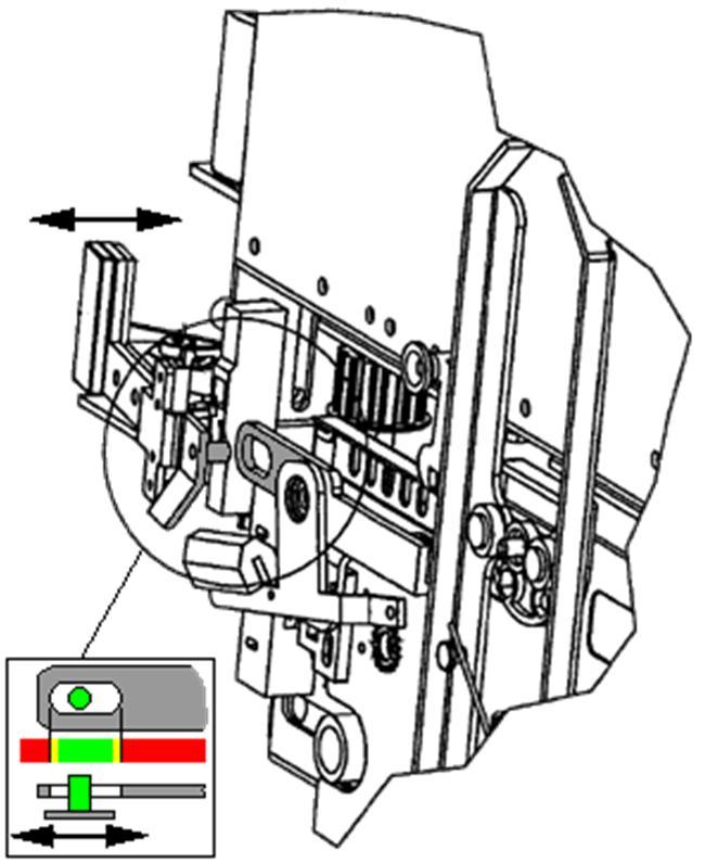
29 SYSTEMS GLT Σ - GLPM 29 / 36 7 DEVICES AND PROCEDURES FOR GLPM SYSTEM 7.1 DEVICES FOR MRL WORKING AREA IN WELL The traction machine is placed in the lift well and it is necessary to install the following devices UPPER CAR STOP MECHANICAL DEVICE (UCSMD) NOTE 3500 min 2000 The dimensions in the left side layout refer to a standard system. The installation of the car stop mechanical device must always be carried out in accordance with the dimensions of the project design min 500 ~1150 SBA OFF T82 T90 T125 ON SBA T82 T T RIGHT POSITION OF THE DEVICE During installation of the mechanical device it is mandatory to respect the rule EN81-20 and follow the instructions below: The car mechanical stop device should be installed: - To prevent uncontrolled or unexpected car movement when machinery is to be maintained or inspected from the pit, as specified at section of the rule EN To give the possibility to leave the working area safety as specified at section of rule EN and it must be fixed to the guide, under the traction machine, at a height such that it is granted: - A free height of at least 2000 mm between the work surface above the car roof and the well ceiling; - If there is no trap door on the cabin roof, a free distance of 500 mm between the top of the clear opening of the landing door and the top of the operator on the car roof. For standard systems, the position corresponds to a height of about 1150 mm above the level of the higher floor. The car mechanical stop device, once activated, prevents to move the sling (and the car), blocking the system.
30 30 / 36 SYSTEMS GLT Σ - GLPM T2 = = M M 12x35 M 12x35 M 12 M 4x30


31 SYSTEMS GLT Σ - GLPM 31 / LOCK DEVICE FOR DOOR OPERATOR AND DOORS 2AT LOCK DEVICE - DOOR OPERATOR 2AT

32 32 / 36 SYSTEMS GLT Σ - GLPM LOCK DEVICE - LANDING DOOR 2AT OTHER DEVICES To guarantee the required safety standards is necessary to install the following devices: UNLOCKING TRIANGLE WITH ELETRICAL SAFETY SWITCH The unlocking triangle, through a direct connection, operate on an electrical safety contact that when you unlock the door it stop any movement of the lift. The electrical safety switch should be connected to the control panel according to the electrical scheme (SCC01, SCC02, SCC12 on S.e.a. scheme, beginning from the lower floor). 7.2 NOTICES, MARKINGS AND OPERATING INSTRUCTION ATTENTION All labels, notices, markings and operative instructions shall be legible and readily understandable. They shall be placed in a visible position and written in the language of the country where the lift is installed. This notices shall be installed as shown in the instructions supplied.

. Do not lean on nor sit on the traction machine. Do not set containers with liquids on the clamp board (danger of short-circuit). Always inform the responsible of the arrival.")

33 SYSTEMS GLT Σ - GLPM 33 / 36 8 EXAMINATIONS AND TESTS At the end of the installation it s necessary to proceed with examinations and tests of the lift. Carry out the tests indicated in chapter 6 of the EN81-20 standard, referring the instructions of the system putting on service manual. 9 FINAL OPERATIONS 9.1 ADVICES Verify that non authorised personnel should not enter into the machine room (always keep it locked) Verify that all protections are mounted on the power unit (electrical connections covering, tank). Do not lean on nor sit on the traction machine. Do not set containers with liquids on the clamp board (danger of short-circuit). Always inform the responsible of the arrival. Before setting the plant out of work, hang the out of service signs to every landing door. Do not leave components, parts, tools, oil or grease stains on the floor. Pay attention to any contact when operating on rotating devices or on devices that remained under tension. ATTENTION Never exclude the safety circuits. Before moving the lift-car, verify the correct operation of the emergency button on the roof. During the movement tightly support with the post or other parts of the lift-car and in any case not with the ropes. Pay particular attention during the upward travel. At the end of the operations, please verify that all protections have been mounted and lock the machine room. 9.2 FINAL OPERATIONS At the end of the installation it is necessary to perform a test of the plant, in compliance with the standards in force. This test is performed by the installer (if qualified by a certified Quality System in compliance with UNI EN ISO 9000) or by a notified organism according to the Lift Standards If the test gives a positive result, it is necessary to communicate that the installation has been performed, indicating: - The address of the building. - The speed, the rated load, the travel, the number of stations and the starting type - Name or name of the company of the installer. - Copy of the compliance certificate. - Name of the company in charge of the maintenance of the plant - Name of the individual in charge of the periodical maintenance interventions on the plant
34 34 / 36 SYSTEMS GLT Σ - GLPM
35 SYSTEMS GLT Σ - GLPM 35 / 36


 TEL.")

36 36 / 36 SYSTEMS GLT Σ - GLPM FLUID DYNAMIC EQUIPMENTS AND LIFT COMPONENTS GMV SPA VIA DON GNOCCHI, PERO MILANO (ITALY) TEL FAX STRADA PER BIANDRATE, 110/ NOVARA (ITALY) TEL FAX INFO@GMV.IT FILE: GLPM-MI EN-200.DOCX - (J2)
GREEN LIFT FLUITRONIC SYSTEM
 SELL TECH WORK CUST USER 10991458 EN *10991458EN* English MI GREENLIFT ORIGINAL INSTRUCTIONS INSTALLATION MANUAL GREEN LIFT FLUITRONIC SYSTEM FOR SYSTEMS: q GLF MR q GLF MRL MC q GLF MRL T q REDUCED HEADROOM
More than lifts worldwide with GMV technology GOODS LIFT PASSENGER & VEHICLE LIFT GLP-VLT.
 More than 800. 000 lifts worldwide with GMV technology GOODS LIFT PASSENGER & VEHICLE LIFT GLP-VLT www.gmv.it MAIN ADVANTAGES TO CHOOSE GOODS LIFT PASSENGER & VEHICLE LIFT GLP-VLT 1 RELIABLE IN SERVICE
More than lifts worldwide with GMV technology HOME LIFTY MRL.
 More than 800. 000 lifts worldwide with GMV technology HOME LIFTY MRL www.gmv.it MAIN HOME LIFTY ADVANTAGES COMFORT The only Home Lift in the market with an MRL solution (Machine Room Less) with NGV electronic
TRACTION MRL LIFT ATLAS EU 2:1. Installation manual /39
 TRACTION MRL LIFT Installation manual 26.08.204 /39 Table of contents. ABOUT THIS DOCUMENT... 4. Document information.... 4.2 Safety warnings definition.... 4.3 Scope of supply.... 4.4 Information concerning
TANKS-POWER UNITS INSTALLATION, USE AND MAINTENANCE MANUAL FOR POWER UNITS: HL, GL, F1, T2, T3, T4 2T2, 2T3, 2T4 HL-COMPACT, HLV, HLV40 MRLT, MRLH
 ITALIANO MI SERBATOI E CENTRALINE SELL TECH WORK CUST USER 10991439 EN *10991439EN* ORIGINAL INSTRUCTIONS INSTALLATION, USE AND MAINTENANCE TANKS-POWER UNITS MANUAL FOR POWER UNITS: HL, GL, F1, T2, T3,
ENGINE WINCHES from 300 to 5000 kg - TS and TD Series
 ENGINE WINCHES from 300 to 5000 kg - TS and TD Series INSTRUCTION MANUAL START-UP AND MAINTENANCE In an endeavor to improve its products, HUCHEZ reserves the right to alter the equipment described herein,
MGV25.X USER GUIDE. Ver. 3.1 INSTALLATION OPERATION AND MAINTENANCE MANUAL OF THE GEARLESS MGV25.X
 MGV25.X USER GUIDE INSTALLATION OPERATION AND MAINTENANCE MANUAL OF THE GEARLESS MGV25.X Ver. 3.1 MONTANARI GIULIO & C. S.r.l. 41100 MODENA (Italy) Via Bulgaria,39 Tel. +39 059 45.36.11 Fax +39 059 31.58.90
MGV25.X USER GUIDE. Ver. 3.7 INSTALLATION OPERATION AND MAINTENANCE MANUAL OF THE GEARLESS MGV25.2 MGV25.3 MGV25.5
 MGV25.X USER GUIDE INSTALLATION OPERATION AND MAINTENANCE MANUAL OF THE GEARLESS MGV25.2 MGV25.3 MGV25.5 Ver. 3.7 MONTANARI GIULIO & C. S.r.l. 41100 MODENA (Italy) Via Bulgaria,39 Tel. +39 059 45.36.11
GENERAL WARNING. General instructions. Technical assistance. Doseuro S.r.l. Liability
 Diaphragm interposed fluid head Use and maintenance manual Model Model BR Model UK Positive displacement metering pump PDP Series Type B I 250 I 350 SD GENERAL WARNING General instructions We thank you
BUREAU OF INDIAN STANDARDS DRAFT FOR COMMENTS ONLY. (Not to be reproduced without the permission of BIS or used as an AMENDMENT)
") Doc: ET 25(6345) BUREAU OF INDIAN STANDARDS DRAFT FOR COMMENTS ONLY (Not to be reproduced without the permission of BIS or used as an AMENDMENT) DRAFT AMENDMENT NO. 3 TO IS 14665 (Part 2 / Sec 1) : 2000
Doc: ET 25(6345) BUREAU OF INDIAN STANDARDS DRAFT FOR COMMENTS ONLY (Not to be reproduced without the permission of BIS or used as an AMENDMENT) DRAFT AMENDMENT NO. 3 TO IS 14665 (Part 2 / Sec 1) : 2000
Plunger Heads Use and Maintenance Manual
 Plunger Heads Use and Maintenance Manual UK Positive displacement dosing pump Type PDP Series A-I 175 A-I 250 A-I 350 General instructions We thank you for choosing this product and recommend you read
BELT CONVEYOR CB/M5 Series
 BELT CONVEYOR CB/M5 Series User and maintenance manual 1 DECLARATION OF CONFORMITY The company: Tel. +39-0444 450 620-451 520 Fax +39-0444 671 840 declares under its own responsibility that the machine
Electrically Released Brakes ERS VAR11-01 FT = 4100 N
 SM429gb - rev 06/11 S E R V I C E Electrically Released Brakes ERS VAR11-01 FT = 4100 N M A N U A L EC type certificate ABV 775/1 According to drawing 1 12 106946 TUV SUD Industrie Service WARNER ELECTRIC
Star Swivel-Arm Hoist Installation and Operating Instructions
 Star Swivel-Arm Hoist Installation and Operating Instructions Conveying & Hoisting Solutions P/L ABN 78 6 7. Purpose of Equipment Star Swivel-Arm Hoists are intended for the transport of materials. Star
PNL-MS Belt Conveyor with Metal Detector
 PNL-MS Belt Conveyor with Metal Detector Date: Apr, 2013 Version: Ver.B (English) Contents 1. General Description... 7 1.1 Coding Principle... 8 1.2 Features:... 8 1.2.1 Specifications Table... 10 1.2.2
SERVO MOTORS BRUSHLESS SERVO MOTORS OPERATING INSTRUCTIONS 2016
 SERVO MOTORS BRUSHLESS SERVO MOTORS OPERATING INSTRUCTIONS 2016 3009/16 en Ed.02.2016 Read these Operating Instructions before performing any transportation, installation, commissioning, maintenance or
Installation manual ASTER AUTOMATION FOR SWING GATES 11_16
 Installation manual ASTER AUTOMATION FOR SWING GATES 11_16 Contents 1. GENERAL SAFETY PRECAUTIONS... page 01 2. INTENDED USE AND APPLICATION... page 01 2.1 Kit contents... page 01 2.2 Technical features...
CO 3-WAY PNEUMATIC VALVE INSTRUCTION MANUAL 2080
 CO 3-WAY PNEUMATIC VALVE INSTRUCTION MANUAL 2080 STI S.r.l has taken every care in collecting and verifying the documentation contained in this Instruction Manual. The information herein contained are
L /2013 rev 0 BISON 35 OTI UNIONE NAZIONALE COSTRUTTORI AUTOMATISMI PER CANCELLI, PORTE SERRANDE ED AFFINI
 L8543019 04/2013 rev 0 BISON 35 OTI UNIONE NAZIONALE COSTRUTTORI AUTOMATISMI PER CANCELLI, PORTE SERRANDE ED AFFINI 1 458 250 A F 645 477 B 195 470 270 2 C 13 ±5 156 70 2 3 4 D2 R D2 I D1 T 5 W D H G R
FITTING AND CONNECTION INSTRUCTIONS
 LEPUS is an oil-bathed motor-reducer created for sliding gates automation. The motor-reducer irreversibility allows a perfect and safe gate closing avoiding the setup of an electrolock and in case of power
BAH series Use and Maintenance Manual
 Page 1 of 15 BAH 225-280 series Use and Maintenance Manual Page 2 of 15 We would like to thank you for trusting us and buying our product. Field of application Before starting the motor, it s necessary
A company of ThyssenKrupp Elevator. ThyssenKrupp Aufzugswerke. Operating Manual. Oil buffer
 A company of ThyssenKrupp Elevator ThyssenKrupp Aufzugswerke Operating Manual Oil buffer OPERATING MANUAL Printer s imprint All rights reserved. Copyright by: THYSSENKRUPP AUFZUGSWERKE GMBH P.O. box 23
MRL CAR FRAME AND MACHINE CHASSIS INSTALLATION MANUAL
 MRL CAR FRAME AND MACHINE CHASSIS INSTALLATION MANUAL Contents i. Introduction... 3 ii. Safety Rules and Warnings... 3 iii. Shipping and Storage Suggestions... 3 1. Car Frame Installation Guide... 4 1.1.
BULL 424 ESA BULL 624 ESA
 L8542677 01/2012 rev 1 BULL 424 ESA BULL 624 ESA UNIONE NAZIONALE COSTRUTTORI AUTOMATISMI PER CANCELLI, PORTE SERRANDE ED AFFINI 1 140 260 92 83 330 330 210 326 2 X BULL.P3 34 mm = = 3 3 4 P P D 102 mm
BELT CONVEYOR PNL/4 Series User and maintenance manual
 BELT CONVEYOR PNL/4 Series User and maintenance manual 1 DECLARATION OF CONFORMITY CE In conformity with the 2006/42/CE Machine Directives, Enclosure II, section A The company: VIRGINIO NASTRI S.r.l. Tel.
USER INSTRUCTIONS FOR SLIDING DOORS
 ENGLISH USER INSTRUCTIONS FOR SLIDING DOORS SL3L LIGHT SL4A ADVANCED SL5A ADVANCED SL5H HEAVY SLTA TELESCOPIC-ADVANCED SL4E EMERGENCY SL5E EMERGENCY SL5B BIG SLTE TELESCOPIC-EMERGENCY FACE S.p.A. Viale
Instruction manual and installation guide Traction sheave brake TSB TSB
 Instruction manual and installation guide Traction sheave brake TSB 2000-1 TSB 2000-2 Content Traction sheave brake Page 1. Safety 2 1.1 Explanation of symbols 2 1.2. General safety instructions 3 2. Product
Before equipment use, please read this operation manual carefully. Serial Number: Date Purchased:
 Pushed & Geared Trolleys OPERATION MANUAL This operation manual is intended as an instruction manual for trained personnel who are in charge of installation, maintenance, repair etc. Before equipment use,
Electrically Released Brakes ERS VAR10 SZ 5000/5000
 SM366gb - rev 01/06 S E R V I C E Electrically Released Brakes ERS VAR10 SZ 5000/5000 M A N U A L EC type certificate ABV 604/1 according drawing 1 12 106602 WARNER ELECTRIC EUROPE Rue Champfleur, B.P.
SPARKSCAN1 HIGH VOLTAGE CLAMP OPERATING MANUAL
 SPARKSCAN1 HIGH VOLTAGE CLAMP OPERATING MANUAL MOTORTECH Tools & Test Equipment for Ignition Systems P/N 01.10.019 Rev. 01/2013 Copyright Copyright 2012 MOTORTECH GmbH. All rights reserved. Distribution
_ ANCHOR LOAD CELLS USER MANUAL
 _ ANCHOR LOAD CELLS USER MANUAL INDEX IntroduCTION Description PRELIMINARY CHECK InstallaTION TAKING MEASUREMENTS DATA MANAGEMENT Troubleshooting MAINTENANCE Page 4 Page 4 Page 5 Page 6 Page 8 Page 8 Pag.
Translation of the Original operating instructions Lifting device Z 70 /...
 Translation of the Original operating instructions Lifting device Z 70 /... Content 1. Lifting device / Correct use according to regulations 2. Basic principles 3. General information 4. Special remarks
Minimum headroom height 2400mm. Minimum pit heigth 150mm. Load of 250/385Kg, capacity for 3 passengers or wheelchair and companion.
 FHL is a platform designed as much for existing homes as for new buildings, of public or private use. FHL is the perfect solution for major or physically handicapped persons, thanks to FHL it is possible
Sheet n 1 of 20 Doc. n WDMM/02/E MOD. WDMM INSTALLATION, USE AND SERVICE MANUAL. PETROL INSTRUMENTS S.r.l APRILIA (LT) - ITALY
 - ITALY") Sheet n 1 of 20 WATER DRAW/ MASTER METER PETROL COUNTER MOD. WDMM INSTALLATION, USE AND SERVICE MANUAL PETROL INSTRUMENTS S.r.l. - 04011 APRILIA (LT) - ITALY Sheet n 2 of 20 INSTALLATION, USE AND SERVICE
Sheet n 1 of 20 WATER DRAW/ MASTER METER PETROL COUNTER MOD. WDMM INSTALLATION, USE AND SERVICE MANUAL PETROL INSTRUMENTS S.r.l. - 04011 APRILIA (LT) - ITALY Sheet n 2 of 20 INSTALLATION, USE AND SERVICE
SCOPELITE TIMING LIGHT OPERATING MANUAL
 SCOPELITE TIMING LIGHT OPERATING MANUAL MOTORTECH Tools & Test Equipment for Ignition Systems P/N 01.10.020-EN Rev. 11/2015 Copyright Copyright 2015 MOTORTECH GmbH. All rights reserved. Distribution and
MG300 USER GUIDE. Ver. 3.2 INSTALLATION OPERATION AND MAINTENANCE MANUAL OF THE GEARLESS MG300.4, MG300.6, MGV30.4 AND MGV30.6
 MG300 USER GUIDE INSTALLATION OPERATION AND MAINTENANCE MANUAL OF THE GEARLESS MG300.4, MG300.6, MGV30.4 AND MGV30.6 Ver. 3.2 MONTANARI GIULIO & C. S.r.l. 41100 MODENA (Italy) Via Bulgaria,39 Tel. +39
E R A I GATE AUTOMATION DIVISION
 S E R A I GATE AUTOMATION DIVISION INSTALLATION MANUAL MC/5C - 03.5C UNDERGROUND MOTOR 230 Vac FOR WING GATES UP TO 3,00m AND 300 Kg EACH WING + FOUNDATION BOX IN HOT-GALVANISED STEEL Thank you for choosing
Operating Instructions. Parallel shaft cam gear
 Operating Instructions Parallel shaft cam gear Type : Serial No. : C O N T E N T S 1. General 1.1 Validity 1.2 Safety instructions 1.3 Shipment 1.4 Transport Regulations 1.5 Weights of gear types 2. Instructions
OGB PolyTrend (8070) Intensive Care Incubator Service Manual
 Intensive Care Incubator Service Manual") OGB PolyTrend (8070) Intensive Care Incubator Service Manual OGB Polytrend Service Manual THIS MANUAL HAS BEEN REALIZED RESPECTING THE ENFORCED NORMS. S/N This manual refers to the enclosed equipment:
OGB PolyTrend (8070) Intensive Care Incubator Service Manual OGB Polytrend Service Manual THIS MANUAL HAS BEEN REALIZED RESPECTING THE ENFORCED NORMS. S/N This manual refers to the enclosed equipment:
L /2012 rev 0 BISON 30 OTI UNIONE NAZIONALE COSTRUTTORI AUTOMATISMI PER CANCELLI, PORTE SERRANDE ED AFFINI
 L8542968 07/2012 rev 0 BISON 30 OTI UNIONE NAZIONALE COSTRUTTORI AUTOMATISMI PER CANCELLI, PORTE SERRANDE ED AFFINI 1 458 250 A F 645 477 B 195 470 270 2 C 13 ±5 156 70 2 3 4 D2 R D2 I D1 T 5 W D H G R
Operating instructions
 Operating instructions Digital tank contents indicator DTA 10 DTA 10 DTA 10 0 4.0 m fuel oil 0 3.5 m water Read instructions before using device! Observe all safety information! Keep instructions for future
Mod: KLD6-12/35XLAS-N
 12/2011 Mod: KLD6-12/35XLAS-N Production code: 1914070 INSTRUCTION MANUAL LOGIC LINE PLUS HOOD Reseller Stamp for Warranty Dear customer, Above all, thank you for choosing our product and we would like
FLEXIBLE COUPLINGS RU-STEEL Annex Atex 95
 FLEXIBLE COUPLINGS RU-STEEL Annex Atex 95 Index: 1 Coupling s Choice 2 Assembly and Alignment 3 Simultaneous Alignment Check 4 Coupling s Guard 5 Check Intervals 6 Extraordinary Malfunctions, Causes and
Operating and Maintenance Manual. for. HADEF overhead crane. as jointed crane TA
 5.52.714.00.1.0 Edition 03.2004 GB Operating and Maintenance Manual for HADEF overhead crane as jointed crane TA Subject to changes. 1 HADEF Table of Contents 1 General Page 3 2 Product description Page
Rotary Limit Switches Driver FRS Series
 Rotary Limit Switches Driver FRS Series TM Limit Switches Driver FRS Series Main Features Driver rotary limit switch Series FRS is a device which allows you to control the movement of industrial and building
SYSTEMS GREEN LIFT GLF KG
 Italiano CT GLF TECHNICAL CATALOGUE SELL TECH WORK CUST USER SYSTEMS GREEN LIFT GLF 3 1025 KG SYSTEMS : GLF MR, GLF MRL-MC, GLF MRL-T 19991495 EN *19991495EN* 1 / 1 19991495 EN - 19.07.16 (J5) 2.03 ENG
EC MACHINE DIRECTIVE COMPLIANCE DECLARATION
 EC MACHINE DIRECTIVE COMPLIANCE DECLARATION (DIRECTIVE 89/392 EEC, APPENDIX II, PART B) Manufacturer: FAAC S.p.A. Address: Via Benini, 1 40069 - Zola Predosa BOLOGNA - ITALY Hereby declares that: the 770
SARGON S - M - L. All rights reserved INSTALLATION MANUAL
 INSTALLATION MANUAL Our compliments for your excellent choice. SARGON LINE S (300mm) M (400mm) and L (600mm) electro-mechanical gear motor has been produced for reliability and high quality. This Manual
ov-lifting_bolts_divider - Updated Lifting Bolts
 ov-lifting_bolts_divider - Updated - 09-01-2017 Lifting Bolts Technical Information roduct information Lifting Bolts roduct marking Compliant with 2006/42/EC, and with individual date of manufacture and
AQUATEC R / AQUATEC F / AQUATEC XL. Bathlift Operating instructions
 AQUATEC R / AQUATEC F / AQUATEC XL Bathlift Operating instructions 1 2 3 4 5 6 7 8 9 10 11 Contents 1 General instructions................. 3 1.1 Introduction......................... 3 1.2 Proper use.........................
P.I.R. Terminals, Porto Corsini- Ravenna Italy Site Requirements. Version 2: August 2009
 P.I.R. Terminals, Porto Corsini- Ravenna Italy Site Requirements Version 2: August 2009 www.shell.com/chemicals/transport 1. Name of Installation: P.I.R. Terminals See also General Requirements 2. Physical
Carlos Silva. Program KST03-K40 / KDTsystem. Electronic Controller for Platformlifts. Operation Manual
 Carlos Silva Program KST03-K40 / 08-2011 KDTsystem Electronic Controller for Platformlifts Operation Manual Documentación Sirius K40 - ING Rev. 1 31/08/2011 INFORMATI SAFETY Sirius & Cargo controllers
Installation Manual. stairlift. A 4724 Neukirchen/W, Salling 8 Tel: 07278/ , Fax: 07278/ Mobil: 0664/
 Installation Manual Ω MEGA stairlift A 4724 Neukirchen/W, Salling 8 Tel: 07278/3514-15, Fax: 07278/3514-12 Email: office.lehner@gmx.at Mobil: 0664/1612980 CONTENTS OBSERVE THE FOLLOWING POINTS BEFORE INSTALLATION!...
Bi-Directional Progressive Safety Gear
 Bi-Directional Progressive Safety Gear (PRO 2000-A, PRO 2000-B, PRO 5000) Installation and Operation Instructions PRO 2000-A PRO 2000-B PRO5000 PRODUCT PRO2000-A PRO2000-B PRO5000 Speed, P+Q, [m/s] [kg]
Spa USE AND MAINTENANCE CULTIVATOR MODEL BL300 / BL350
 Spa USE AND MAINTENANCE CULTIVATOR MODEL BL300 / BL350 02/12/2008 INDEX INTRODUCTION TECHNICAL DETAILS GENERAL SAFETY REGULATIONS STARTING AND STOPPING USE AND ADJUSTMENT SERVICING TESTS FOR CE REGULATIONS
VARIFUEL MAINTENANCE AND REPAIR INSTRUCTIONS
 VARIFUEL2 200-120 MAINTENANCE AND REPAIR INSTRUCTIONS MOTORTECH Gas Regulation P/N 01.50.008-200-120-EN Rev. 06/2015 Copyright Copyright 2015 MOTORTECH GmbH. All rights reserved. Distribution and reproduction
Head with piston Use and Maintenance Manual
 Head with piston Use and Maintenance Manual UK Type Positive displacement dosing pump PDP Series A-I 175 A-I 250 A-I 350 General instructions We thank you for choosing this product and recommend you read
BISON 20 OM BISON 25 OTI
 L8542939 11/2011 rev 0 BISON 20 OM BISON 25 OTI UNIONE NAZIONALE COSTRUTTORI AUTOMATISMI PER CANCELLI, PORTE SERRANDE ED AFFINI 2 x 1,5 GND 13 8 7 5 RG 58 4 3 4 x 0,35 6 1 2 4 3 x 1,5 min 230V 2 x 0,35
ASSEMBLY INSTRUCTIONS L-LINE KTG ZMA0304GB
 ASSEMBLY INSTRUCTIONS L-LINE KTG ZMA0304GB 2012-12-01 Delivery information Goods inspection Check that the number of packages agrees with the delivery note and that the packing and goods are not damaged.
Timing-Belt Reverse Unit 8 80 R50 II Notes on Use and Installation
 Timing-Belt Reverse Unit 8 80 R50 II Notes on Use and Installation Content 2 General safety information 3 Correct use 3 Application 4 Technical Data/Scope of Supply 4 Fastening Options 5 Rounding the Profile
Crane Forks. Introduction. Important Notes. Key Benefits. User Guide
 User Guide Crane Forks Introduction Fully self levelling, even when unloaded, Conquip Crane Forks have been designed to lift packs of bricks and pallets. The crane attachment has adjustable forks and a
Northern Sales & Distribution Centre
 User Manual Industrial Door Northern Sales & Distribution Centre The Door Centre, Discovery Park, Crossley Road, Stockport, SK4 5BW /indupart /indupart /indupart /company/indupart-ltd Foreword This user
INSTALLATION MANUAL FOR SWING SHUTTERS KAF212. FACE S.r.l. Viale delle Industrie, Dosson di Casier Treviso Italy
 INSTALLATION MANUAL FOR SWING SHUTTERS KAF212 FACE S.r.l. Viale delle Industrie, 74 31030 Dosson di Casier Treviso Italy INDEX Subject Page 1. General safety instruction 2 1.1 EC marking and European directives
Operating Instructions for Elevator Buffers type LP
 Operating Instructions for Elevator Buffers type LP 1 Scope of application The Elevator Buffer type LP is an energy dissipation type buffer according to EN 81-1/2, EN 81-20, EN 81-50 5.5 and therefore
UNDERGROUND OPERATOR FOR SWINGING GATES. WARNING!! Before installing, thoroughly read this manual that is an integral part of the pack
 UNDERGROUND OPERATOR FOR SWINGING GATES COMPAS 2 WARNING!! Before installing, thoroughly read this manual that is an integral part of the pack Our products if installed by qualified personnel capable to
ov-lifting_bolts_divider - Updated Lifting Bolts
 ov-lifting_bolts_divider - Updated - 09-01-2017 Lifting Bolts Technical Information roduct information Lifting Bolts roduct marking Compliant with 2006/42/EC, and with individual date of manufacture and
L /2012 rev 0 BISON 45 OTI UNIONE NAZIONALE COSTRUTTORI AUTOMATISMI PER CANCELLI, PORTE SERRANDE ED AFFINI
 L8542965 03/2012 rev 0 BISON 45 OTI UNIONE NAZIONALE COSTRUTTORI AUTOMATISMI PER CANCELLI, PORTE SERRANDE ED AFFINI 1 470 327 F A 500 825 B 243.5 2 C 445 210 15 ±5 205 92 50 2 3 4 I D2 D2 D1 5 T 6 D A
Bowl feeder WV401-1 / Translation of operating and installation instructions
 Bowl feeder WV401-1 / 402-1 Translation of operating and installation instructions Copyright by Afag GmbH This operation instruction applies to: Bowl feeder WV401-1 Bowl feeder WV402-1 Type 230 V / 50
DESCRIPTION OF OPERATION EcoSpace elevator with KCM831 control
 Owner s UM-01.26.001-USK All DRAFT KONE Montana 2011 rights Corporation KONE (-) guide reserved Elevator 2011-02-24 Corporation Project DESCRIPTION OF OPERATION EcoSpace elevator with KCM831 control All
INSTALLER MANUAL USER MANUAL. Contents
 Installation & user manual two way Contents INSTALLER MANUAL Important information General 1. Technical data 2. Description Installation: 1. Positioning the unit 2. Connection. 3. Parts description. 4.
Installation and Maintenance Manual for SPANCO A Series Aluminum Gantry Cranes
 Manual No. 103-0008 REV. 6/11 Installation and Maintenance Manual for SPANCO A Series Aluminum Gantry Cranes ISO 9001 REGISTERED SPANCO, Inc. 2 TABLE OF CONTENTS Warnings... 3 Installation... 4 Maintenance...
PROJECTOR LIFT MODEL SIH-300 INSTALLATION MANUAL
 PROJECTOR LIFT MODEL SIH-300 INSTALLATION MANUAL Thank you for purchasing the new SI-H 300 Projector Lift. The SI-H 300 is supplied with a set of components and accessories that make it suitable for installation
Crane Forks. Introduction. Important Notes. Key Benefits. User Guide
 User Guide Crane Forks Introduction Fully self levelling, even when unloaded, Conquip Crane Forks have been designed to lift packs of bricks and pallets. The crane attachment has adjustable forks and a
VARIFUEL MAINTENANCE AND REPAIR INSTRUCTIONS
 VARIFUEL2 140-65 MAINTENANCE AND REPAIR INSTRUCTIONS MOTORTECH Gas Regulation P/N 01.50.008-140-65-EN Rev. 06/2015 Copyright Copyright 2015 MOTORTECH GmbH. All rights reserved. Distribution and reproduction
Installation and maintenance manual T85 STEERING SYSTEM ULTRAFLEX. page. 2 pag. 14 page. 27 PARTNER. (Dr./Dis./Des. n 15079/b 17/02/2015)
") T85 STEERING SYSTEM FRANÇAIS ITALIANO R ULTRAFLEX UK I page. 2 pag. 14 page. 27 F PARTNER (Dr./Dis./Des. n 15079/b 17/02/2015) Dear Customer, We would like to thank you for choosing an ULTRAFLEX product.
T85 STEERING SYSTEM FRANÇAIS ITALIANO R ULTRAFLEX UK I page. 2 pag. 14 page. 27 F PARTNER (Dr./Dis./Des. n 15079/b 17/02/2015) Dear Customer, We would like to thank you for choosing an ULTRAFLEX product.
Goods lift with attendant. Goods only lift
 Goods only lift Goods lift with attendant BOXlift : the high performance goods only lift BOXlift is a goods lift of up to 2000kg rated load, specially designed for use in buildings with high turnover and
BULL 5M - BULL 5M.S BULL 8M - BULL 8 M.S BULL 8 OM - BULL 8 OM.S
 L8542676 04/2012 rev. 2 BULL 5M - BULL 5M.S BULL 8M - BULL 8 M.S BULL 8 OM - BULL 8 OM.S UNIONE NAZIONALE COSTRUTTORI AUTOMATISMI PER CANCELLI, PORTE SERRANDE ED AFFINI 1 140 260 100 91 330 330 210 326
Compact Heat Meters. Features. -A Pulsed output. -B M-Bus output. Accessories. UK Sales Tel: International Tel:
 Compact Heat Meters Features Compact design Simple operation Pulsed output Measures heating or cooling Specification Product Codes Water Meter Temp. range 10 to 90 C Nominal pressure 16bar Installation
NOTES ON ELEVATOR SYSTEMS
 1. Electrohydraulic Lifts 2. Escalators 3. Electrical Requirements 4. Ventilation in Lift Machine Room 5. Lifts for Persons with Limited Mobility Disclaimer 1 Electrohydraulic Lifts Pascal's law of fluid
Type 0283, Operating Instructions. Bedienungsanleitung Manuel d utilisation. 2/2-way solenoid valve 2/2-Wege-Magnetventil Électrovanne 2/2 voies
 Type 0283, 0293 2/2-way solenoid valve 2/2-Wege-Magnetventil Électrovanne 2/2 voies Operating Instructions Bedienungsanleitung Manuel d utilisation Contents 1 The operating instructions...2 2 Intended
Gunnebo Lifting Offshore programme - accessories. High consistent quality generates long durability and safety
 Gunnebo Lifting Offshore programme - accessories High consistent quality generates long durability and safety DNV 2.7-1 certificate We are certified by DNV to make type approval in 271 quality (Offshore
Control Gate Valve with stepper motor actuator
 Control Gate Valve with stepper motor actuator This manual is valid for the valve ordering numbers: 64036-.E52 and 64040-.E52 The respective product identification is given on each valve in the following
Installation, operation and maintenance manual
 Installation, operation and maintenance manual HCT1LX30 FULL RISE SCISSOR LIFT READ THIS ENTIRE MANUAL BEFORE INSTALLATION TO ENSURE CORRECT OPERATION AND A LONG SERVICE LIFE 2 Tiraines str. Riga, LV 1058
Bowl feeder BF20 / BF25 / BF30 BF35 / BF40 / BF50
 Bowl feeder BF20 / BF25 / BF30 BF35 / BF40 / BF50 Translation of operating and installation instructions Copyright by Afag GmbH This operation instruction applies to: Type Order number BF20 BF25 BF30 BF35
SAFETY GUIDANCE MATERIAL
 SAFETY GUIDANCE MATERIAL SAFETY OPERATIONS GUIDANCE MONDAY MARCH 23, 2015 This safety resource was written for the scrap industry by the scrap industry and was developed to assist you in making your scrap
INSTALLATION MANUAL FOR EVO BRAKES
 INSTALLATION MANUAL FOR EVO BRAKES DATE OF CREATION: 18/03/2013 DATE OF REVIEW: 13/11/2017 REACH: EVO-01/EVO-05 REVIEW: ES13 1 / 31 ÍNDICE 1 SAFETY INSTRUCTIONS:... 3 1.1 Symbols used:... 3 1.2 General
Provided by: Operating, Maintenance & Parts Manual
 Provided by: www.hoistsdirect.com TB681.qxd 11/29/2004 3:04 PM Page 1 Operating, Maintenance & Parts Manual TB603 Manually Lever Operated Chain Hoist 1100 POUNDS MAXIMUM CAPACITY (500 kg) Follow all instructions
OPERATING INSTRUCTIONS. ASTRO HOIST Type E89-CTO
 OPERATING INSTRUCTIONS ASTRO HOIST Type E89-CTO CONFORM TO EN 1808 - MARCH 1999 MACHINE DIRECTIVE 98/37 EC All persons operating this equipment must read and completely understand this manual. Any operation
Electronic Testing Category 5
 Electronic Testing Category 5 Kevin Heling, March 13, 2018 WE START HERE: Rope load measuring sensors (Henning Mobile Weight Watcher System): foundation of the Alternative Testing Method (electronic testing)
LIMITADOR DE VELOCIDAD DYNATECH/ DYNATECH OVERSPEED GOVERNOR/ LIMITEUR DE VITESSE DYNATECH/ GESCHWINDIGKEITSBEGRENZER DYNATECH/ VEGA
 LIMITADOR DE VELOCIDAD DYNATECH/ DYNATECH OVERSPEED GOVERNOR/ LIMITEUR DE VITESSE DYNATECH/ GESCHWINDIGKEITSBEGRENZER DYNATECH/ VEGA INSTRUCCIONES DE USO Y MANUTENCIÓN/ INSTRUCTIONS FOR USE AND MAINTENANCE/
Heavy Duty Engine Cranes
 Heavy Duty Engine Cranes Operating Instructions & Parts Manual Model Number Atd-7484 Atd-7485 (Foldable Legs) Capacity 2 Ton 2 Ton Model Atd-7484 Model Atd-7485 Atd Tools Inc. 160 Enterprise Drive, Wentzville,
Product Information Overspeed governor GB 260
 Product Information GB 260 Copyright as per DIN ISO 16016. Manufactured under licence of C. Haushahn GmbH & Co. I Subject to modification. Published by SLC Sautter Lift Components GmbH & Co. KG Borsigstrasse
SpeedHook. Concrete Cutting System OPERATOR S MANUAL ICS, Blount Inc. F/N Oct 07
 SpeedHook Concrete Cutting System OPERATOR S MANUAL 2007 ICS, Blount Inc. F/N 70569 Oct 07 SpeedHook OPERATOR S MANUAL TABLE OF TITLE CONTENTS SYMBOLS & LABELS 4 SAFETY 5 TECHNICAL SPECIFICATIONS 6 SET-UP
Likorall. LOAD TESTING 12 Mechanical lowering load test (242) Maximum load rail system... DOCUMENTATION 14 Instructions / Instruction guide...
 Maximum load rail system... DOCUMENTATION 14 Instructions / Instruction guide...") 6.1 Likorall 200, 240, 242, 243, 250 Periodic inspection 24-06-26 Lift type:... Prod No:... Version: Serial No:... Prod. Year:... Customer Reference: Contract No:... Name:... Address:... (Zip Code)...
6.1 Likorall 200, 240, 242, 243, 250 Periodic inspection 24-06-26 Lift type:... Prod No:... Version: Serial No:... Prod. Year:... Customer Reference: Contract No:... Name:... Address:... (Zip Code)...
Portable Ladder Safety
 Portable Ladder Safety Disclaimer This training material presents very important information. Your organization must do an evaluation of all exposures, applicable codes and regulations, and establish proper
INSTRUCTION MANUAL BR 25 FOR RAILWAY APPLICATION 5COR BR25AT REV00
 INSTRUCTION MANUAL BR 25 FOR RAILWAY APPLICATION 5COR469100 BR25AT REV00 I CONTENT: 1 SAFETY 1.1 Safety instructions 1 1.2 Specified applications 1 1.3 Safety notes on the equipment operation 1 2 BR 25
AC 100. Operating instructions Pneumatic Crimper AC 100. Date of issue: 05/2010. Keep for future use!
 Operating instructions Pneumatic Crimper AC 100 Date of issue: 05/2010 Keep for future use! SAFETY SAFETY Basic information The basic prerequisite for ensuring safe use and continuous operation of the
INSTALLATION INSTRUCTIONS AMBASSADOR DRUM OVERHEAD SERIES 100 DUMBWAITER
 INSTALLATION INSTRUCTIONS AMBASSADOR DRUM OVERHEAD SERIES 100 DUMBWAITER The installation of Matot Drum Dumbwaiters should only be performed by qualified, experienced, and trained elevator installers.
Inverter / Charger Accessory for Steca Solarix PLI Phase / Parallel Kit. Installation and operating instructions Z01 17.
 Inverter / Charger Accessory for Steca Solarix PLI 5000-48 3-Phase / Parallel Kit Installation and operating instructions GB Z01 17.31 Table of Contents About this Manual... 2 Purpose... 2 Scope... 2 Keywords
Creating An Accessible World ELVORON CPL.
 Creating An Accessible World ELVORON CPL Design And Planning Guide www.garaventalift.com Please note: Dimensions provided in this Guide are for REFERENCE ONLY and should not be used for site preparation