PowerChute TM Network Shutdown v4.0. User Guide. VMware
|
|
|
- Megan Tate
- 5 years ago
- Views:
Transcription

1 PowerChute TM Network Shutdown v4.0 User Guide VMware C-001 Publication Date: January 2015
2 Table of Contents Introduction... 1 UPS Configuration... 2 Network Configuration... 3 UPS Configuration Options... 4 Network Management Card Connection... 7 Advanced UPS Setups... 9 Outlet Group Registration Network Management Card Settings VMware Configuration Standalone VMware Host Details vcenter Server Settings VMware Host Protection Advanced UPS configuration Physical UPS Setup Power Protection Virtualization Settings Virtual Machine Migration Virtual Machine Shutdown/Startup vapp Shutdown/Startup PowerChute vsphere Plugin Active Directory VMware Configuration Shutdown Settings UPS Shutdown Shutdown Command Files Shutdown Settings for Advanced UPS Configurations Event Configuration Notifications Event-Driven Command Files Shutdown Actions Sequenced Server Shutdown Sample Shutdown Scenarios VMware: UPS without Outlet Groups VMware: UPS with Outlet Groups VMware Shutdown - Single UPS Configuration VMware Shutdown - HA Cluster VMware Shutdown - Advanced UPS Configuration PowerChute Events and Logging Configurable Events Configurable Environmental Events Non-Configurable Events Configuration (INI) File Events VMware Virtualization Events ii
3 Table of Contents Critical Events in a Redundant-UPS Configuration Critical Events in a Parallel-UPS Configuration General Communications Settings PowerChute Agents PowerChute Configuration File User Interface Session Timeout Check for Updates Customer Support Troubleshooting Network Management Card Troubleshooting VMware Troubleshooting Browser Troubleshooting iii
4 Introduction PowerChute TM Network Shutdown (PowerChute) works in conjunction with the UPS Network Management Card (NMC) to provide network-based shutdown of multiple computer systems. In the case of a UPS critical event, the software performs a graceful, unattended system shutdown before the UPS battery is exhausted. The number of protected systems is limited only by the capacity of the UPS. View these Application Notes for detailed information on using PowerChute in specific environments. After installation, it is essential to configure the software using the PowerChute Setup wizard. This ensures that PowerChute is aware of UPS critical events in order to protect your system. 1
5 UPS Configuration This section contains information on the topics below: Network Configuration UPS Configuration Options Network Management Card Connection Advanced UPS Set-ups Outlet Group Registration Network Management Card Settings 2
6 UPS Configuration Network Configuration PowerChute can use IPv4 or IPv6 to communicate with the Network Management Card(s). Select IP If your computer has more than one IPv4 address you will need to select one of the available addresses. The IP address you select will be registered with the NMC and displayed in the NMC user interface under Configuration - PowerChute Clients. IPv6 Configuration If you are using IPv6 to communicate with the NMC(s), each network adapter on your machine will typically have several IP addresses assigned to it. Each adapter will have at least one link-local address and one global unicast address assigned to it. Use the Unicast IP Address drop-down box to specify which address to use. The address type selected in this drop-down box must match the address type that you enter for the NMC(s) on the Network Management Card Connection page. This unicast address will be registered on the NMC(s) and displayed on the PowerChute Network Shutdown Clients page of the NMC. fe80::88c8:3d95:bc02:74cc is an example of a link-local address. 2001:112:1:0:88c8:3d95:bc02:74cc is an example of a global unicast address. Multicast Option The NMC supports sending communication packets to an IPv6 Multicast address instead of sending unicast packets to each PowerChute agent. To use this, enable the Multicast check box and enter an IPv6 Multicast address. The multicast address that is entered here will be registered on the NMC(s) instead of the unicast address and displayed on the PowerChute Network Shutdown Clients page of the NMC. The NMC(s) will send communication packets to that multicast address. FF02::1 is an example of a multicast address with link-local scope so that only nodes on the same physical network segment will receive it. If using a link-local unicast address, you must use a multicast address with link-local scope. FF0E::1 is an example of a multicast address with global scope and the NMC will use its global unicast address to send the packet. If using a global unicast address you must use a multicast address with global scope. For detailed information, please view "The Communications Process of PowerChute Network Shutdown" here. 3

7 PowerChute Network Shutdown: VMware User Guide UPS Configuration Options For a detailed overview of which UPS s support each configuration, please view the PowerChute Network Shutdown Operating Modes and supported UPS Configurations Application Note here. Single-UPS Configuration Redundant-UPS Configuration 4

8 UPS Configuration For detailed information, please view Using PowerChute Network Shutdown in a Redundant-UPS Configuration Application Note here. Parallel-UPS Configuration Note: To use the Parallel-UPS configuration, your UPS devices must already be configured to operate in parallel mode. For detailed information, please view Using PowerChute Network Shutdown in a Parallel-UPS Configuration Application Note here. 5

9 PowerChute Network Shutdown: VMware User Guide Advanced UPS Configuration Standalone VMware hosts and hosts managed by vcenter Server are supported for Advanced UPS Configuration. * Virtualization Manager Server is vcenter Server A single PowerChute Agent can manage all the UPS s in the cluster. Each UPS protects one or more VMware Hosts. For detailed information, please view the Using PowerChute Network Shutdown in an Advanced Redundant Setup Application Note here. 6

10 UPS Configuration Network Management Card Connection The Network Management Card uses the HTTP protocol by default. This can be changed to HTTPS through the NMC user interface. Based on the NMC protocol used, you can select either HTTP or HTTPS in PowerChute. The default port is 80 for HTTP, and 443 for HTTPS. Do not change this number unless you changed the port being used by your NMC. The NMC uses a self-signed SSL certificate by default when HTTPS is enabled. You need to enable "Accept Untrusted SSL Certificates" to allow PowerChute to establish communication with the NMC if a self-signed cert is being used by the NMC. For Redundant and Parallel configurations, you need to enter more than one IP address to enable communications with all the relevant NMCs. For more information on UPS configurations and supported UPS models, view the Application Note "PowerChute Network Shutdown Operating Modes and supported UPS Configurations" here. Add each IP address using the + Add IP Address button. Enter the IP address of the NMC in the UPS. Click OK. To edit an IP address click the icon. To delete an IP address, click the icon. Adding a Trusted Certificate to PowerChute for NMC communication When using the HTTPS protocol to communicate with the NMC, you must select the Accept Untrusted SSL Certificates? check box. However, it is possible to create a Trusted Certificate file and add it to the PowerChute truststore. Your NMC user s guide has details on the Security Wizard used to create the Trusted Certificate file with an extension.crt. This file is then used to create components that can be uploaded to the NMC to replace the default self-signed certificate. In order to facilitate the trusted SSL communication of PowerChute with the NMC, this Trusted Certificate file must then be added to the system Java cacerts keystore or to the PowerChutekeystore file. (You can do this using the Java keytool.exe; for details see the Java help 7
11 PowerChute Network Shutdown: VMware User Guide documentation). Adding it to the cacerts keystore means it is available to all your applications as distinct from just PowerChute. By default the PowerChute-keystore file is located in APC\PowerChute\group1. Its password is password. If you add the Trusted Certificate and you subsequently get a connection error with the NMC, then it could be because a) the certificate has expired, b) it is not yet valid, or c) it has been revoked. In any of these cases, you need to add a new Trusted Certificate to the PowerChute server or to upload a new valid SSL certificate to the NMC. The PowerChute-keystore file only exists after the first attempt is made to communicate with the NMC using HTTPS (by using the configuration wizard for example). For this reason, for a silent installation you must add the Trusted Certificate to the Java cacerts keystore. PowerChute only checks the keystore when its service starts. After you add the Trusted Certificate, you will need to re-start the PowerChute service if it s already running. 8

12 UPS Configuration Advanced UPS Setups Add UPS Setup In an Advanced UPS configuration, a single instance of PowerChute Network Shutdown can monitor multiple UPS setups and initiate graceful shutdown of equipment based on different redundancy levels. Each setup can be a single UPS or a UPS group. A single UPS setup is represented by the icon. A UPS group is represented by the icon. For example, one setup may be a group of UPS's that are configured with N+2 redundancy. Another setup may be a single UPS. On the UPS Details page of the Setup Wizard, click the + Add UPS(s) button to create a new setup. To create a setup with a single UPS, on the Configure UPS Setup dialog choose Single UPS: 1. Enter a UPS Setup Name (with a maximum of 20 ASCII characters) 2. Click the + Add IP Address button and enter the IP address of the Network Management card in the UPS. Click OK. 3. Click OK to complete Single UPS Setup. 9

13 PowerChute Network Shutdown: VMware User Guide To create a setup with a group of UPS devices, choose UPS Group: 1. Enter a UPS Setup Name (with a maximum of 20 ASCII characters) 2. Click the + Add IP Address button and enter the IP address of the Network Management card in the UPS. Click OK. 3. Repeat for each of the UPS devices to be added to the UPS group. A minimum of 2 IP addresses is required to set up a UPS Group. 4. Click OK to complete Group UPS Setup. Repeat for each UPS setup required. To edit a UPS Setup, click the icon. To delete a UPS setup, click the icon. Click the Next button to proceed. PowerChute has been tested with a total of 16 NMCs in an advanced configuration. However it is possible to configure for more than 16 NMCs in this configuration. For detailed information, please view the Using PowerChute Network Shutdown in an Advanced Redundant Setup Application Note here. 10
 and nonoutlet-aware UPS s (e.")
14 UPS Configuration Outlet Group Registration If your UPS supports outlet groups you must specify which one the server is being powered by so that PowerChute can monitor it for shutdown events and also issue turn-off commands to that outlet group. UPS Shutdown Behavior in Mixed UPS Environments If your VMware hosts are being powered by a mix of outlet-aware UPS s (e.g. SMX/ SMT) and nonoutlet-aware UPS s (e.g. SU/ SUA) in a Redundant UPS Configuration, PowerChute only provides the option to turn off the UPS and not the outlet group. Your VMware hosts and their virtual machines are still protected if there is a UPS critical event or if the outlet group is commanded to shut down e.g. via the NMC User Interface. This also applies for the Advanced UPS configuration if there are hosts associated with more than one outlet group on the same NMC. PowerChute Setup - VMware hosts associated with more than one outlet group on the same NMC Host Protection - VMware hosts associated with more than one outlet group on the same NMC 11


15 PowerChute Network Shutdown: VMware User Guide Network Management Card Settings For Single, Redundant and Parallel UPS configurations, the IP address of each NMC that PowerChute is communicating with is displayed under the UPS Configuration menu option. For Advanced UPS configuration, each UPS Setup is displayed as a menu item and the IP address of the NMC(s) with which PowerChute is communicating is displayed under each UPS setup. Click on the IP address to view the UPS information specific to that NMC. If the NMC has VMware Hosts associated with it, you can edit these settings for a specific NMC on this page. This overrides the global NMC settings configured via the initial PowerChute Setup or via the Shutdown Settings screen. UPS information displayed includes: NMC IP Address UPS model name UPS configuration The NMC Host Name from the NMC's DNS settings page under Network - DNS - Configuration is also displayed. This is not the same as the UPS name that can be set under Configuration - UPS General on the NMC. Clicking the Launch button opens the NMC user interface. 12
16 VMware Configuration When VMware Support has been enabled the options below are displayed: Choose Standalone VMware Host to protect a single host that is not managed by vcenter Server. Choose Host managed by vcenter Server for HA cluster support and to manage multiple VMware hosts. 13

17 PowerChute Network Shutdown: VMware User Guide Standalone VMware Host Details When deployed as a virtual appliance or installed on a vma, PowerChute connects directly to the VMware host to shut it down using the credentials you enter. PowerChute must be configured to connect to the VMware host using an account with the Administrator role. This can be a local user account or an Active Directory User Account that is a member of the "ESX Admins" Domain Security Group. The "ESX Admins" group needs to be created via "Active Directory Users and Groups". When an ESXi host is joined to an Active Directory domain, VMware automatically assigns the Administrator role to the "ESX Admins" group. 14
18 VMware Configuration 15

19 PowerChute Network Shutdown: VMware User Guide PowerChute does not directly shut down virtual machines with this configuration. In order to gracefully shut down VMs, you must use the Virtual Machine Startup/Shutdown settings for the VMware host in the vsphere Client. This is accessible on the Configuration tab under Software in the vsphere Client. The shutdown action must be changed to "Guest Shutdown". 16

20 VMware Configuration vcenter Server Settings PowerChute connects to the vcenter Server to perform VM migration, VM shutdown, vapp shutdown, and VMware host shutdown operations. It is recommended that you configure an Active Directory user account with the Administrator role for vcenter Server and the VMware hosts being managed by PowerChute. If Active Directory is not available, it is recommended that you configure a local user account with the Administrator role that exists on vcenter Server and on each of the VMware hosts being managed by PowerChute. If vcenter Server is running on a VM you must configure an Active Directory account or shared Local User account for host shutdown commands to work correctly. For more information see Active Directory VMware Configuration. If the vcenter Server is unavailable when a critical UPS event occurs, PowerChute will still be able to connect directly to the VMware hosts using this Active Directory or shared local user account to shut down VMs and the hosts themselves. VM migration and vapp shutdown and startup are not supported if the vcenter Server is unavailable. Communications Settings - Main UI - vcenter Server running on a VM option If vcenter Server is running on a VM, the option vcenter Server Running on a VM should be selected so that PowerChute can perform additional validation when trying to locate the vcenter Server VM and its parent host. DNS/Hostname resolution issues can lead to a problem where PowerChute cannot correctly identify the vcenter Server VM or its parent Host. 17
21 PowerChute Network Shutdown: VMware User Guide This can also occur if VMware Tools are not installed and running on the vcenter Server VM. This results in vcenter Server VM being shut down too early in the sequence along with the other VMs. By enabling the checkbox PowerChute will check for these kinds of problems and display a warning message on the Host Protection page or log an event in the Event Log. If vcenter Server is installed on a Physical machine there is no need to enable this option. The checkbox is only used to aid troubleshooting it does not control whether PowerChute will perform vcenter Server VM shutdown. If unchecked and PowerChute locates vcenter Server running on a VM on an affected Host it will still shut down the Host. For more information on vcenter Server VM shutdown events see Virtualization Events. 18
. From this screen you can select the hosts that PowerChute should protect.")
22 VMware Configuration VMware Host Protection Once connected to vcenter Server, PowerChute displays all of the VMware hosts in the inventory in a tree view (similar to what you see using vsphere client). From this screen you can select the hosts that PowerChute should protect. Single, Redundant, and Parallel-UPS configurations If PowerChute is installed on a physical Windows machine you must specify the VMware hosts in the left-hand panel that you want to protect by dragging them to the right-hand panel of this screen. When a critical UPS event occurs, PowerChute will shut down VMs and the Hosts in the order that they appear in the right-hand panel. You can change this order by clicking on a host in the right-hand panel and dragging it up or down. PowerChute will re-start VMs on each host in the reverse order that they were shut down. If vcenter server or PowerChute is running on a VM they are shutdown after the other hosts, irrespective of the order that they appear in the Host Protection user interface. The other ESXi hosts are shut down in the order that they appear in the UI. If PowerChute is installed on the vma or deployed as a Virtual Appliance, the right-hand panel is automatically populated with all hosts in the same cluster. The host running the PowerChute VM is automatically listed last and can be identified by the logo. If vcenter Server is running on a VM on one of the ESXi hosts in the cluster it can be identified by this logo 19

23 PowerChute Network Shutdown: VMware User Guide If vcenter is running on a VM on one of the ESXi hosts and none of the Hosts are highlighted with the logo, or the wrong Host is highlighted, this indicates there is a configuration issue in vsphere setup that will prevent PowerChute from shutting down the vcenter Server VM correctly. If vcenter Server and PowerChute are running on a VM on one of the ESXi hosts in the cluster it can be identified by these logos together: 20

24 VMware Configuration Advanced UPS configuration The VMware hosts are powered separately by one or more UPS(s). The right-hand panel shows the UPS(s) that PowerChute is registered with. You need to associate each VMware host in the left-hand panel with the UPS by which it is powered. To do this, drag each host to the UPS/UPS group in the right-hand panel. For this configuration, PowerChute must be installed on a physical Windows machine outside the cluster. If the IP address/hostname of the vcenter Server or any of the VMware hosts is changed it will be necessary to re-associate the hosts with the UPS s. When this occurs the following event is logged in the PowerChute event log: Host(s) [Hosts] no longer exist in the vcenter Server Inventory. Please open the Host Protection page and re-select the Hosts that should be protected. 21
. For more information see Shutdown Settings for Advanced UPS Setups.")
25 PowerChute Network Shutdown: VMware User Guide Physical UPS Setup Power Protection In Advanced UPS Setups, PowerChute can monitor UPS's which are powering equipment outside a VMware cluster (e.g. a Storage Array Device or a physical server machine running PowerChute). For more information see Shutdown Settings for Advanced UPS Setups. On the VMware Host Protection page, do not link VMware hosts with the UPS devices that are powering the physical equipment. The following additional options will then be displayed on the Shutdown Settings page: Shutdown PowerChute Server - This is enabled by default and is used to gracefully shut down the physical machine running PowerChute. This option can be disabled if the UPS is powering a Storage Array Device. Execute Virtualization Shutdown Sequence - This triggers a shutdown sequence using the actions configured on the Virtualization Settings page. This option should be enabled for all UPS Setups that are powering physical equipment. 22
26 VMware Configuration 23
27 PowerChute Network Shutdown: VMware User Guide Virtualization Settings Virtual machine (VM) settings like VM migration and VM shutdown can be configured in Virtualization settings. For more information see: Virtual Machine Migration Virtual Machine Shutdown/Startup vapp Shutdown/Startup vcenter Server VM Shutdown Duration is the shutdown duration given to the Virtual Machine on which vcenter Server is running. This is configurable and is set to 240 seconds by default. If vcenter Server is running on a VM and this option is not displayed this indicates a configuration issue with vsphere. For more information see VMware Troubleshooting. PowerChute does not support installation on a host that is part of a vsan enabled cluster. In a configuration that includes a vsan enabled cluster, PowerChute must be installed on a physical machine, or on a host that is not part of the vsan enabled cluster. When PowerChute starts a maintenance mode task via vsphere API it does not pass any arguments for vsan data migration option. Because of this the default option Ensure accessibility is used. 24

28 VMware Configuration Virtualization settings in Advanced UPS Configuration In an Advanced UPS Configuration, settings entered on this page will be applied to all UPS Setups if the check box Apply VM settings to all UPS Setups is selected. This checkbox is enabled by default. If you have applied settings to individual UPS Setups you should uncheck this option to prevent them from being overwritten. Apply VM Settings unchecked 25

29 PowerChute Network Shutdown: VMware User Guide Individual UPS Setup Settings applied 26

30 VMware Configuration Virtual Machine Migration If you enable Virtual Machine migration, use the Duration field to set the time allowed for the VMs to migrate to another healthy Host in the Cluster. VMs will not be migrated to Hosts that are powered off, in a disconnected state, in maintenance mode, or affected by a UPS critical event. Custom Target Host Migration By default, PowerChute will migrate VMs to any available Host in the same cluster. To control where VMs get migrated to, enable the Select target host for Migration option in the Virtualization Settings page of the PowerChute Setup or on the Virtualization Settings page in the main UI. Select target host for Migration - PowerChute Setup Single/Redundant/Parallel UPS Configuration In Advanced configurations, Select target host for Migration is not available in the Setup wizard, to prevent all UPS Setups using the same set of Target Hosts. It is defined in Virtualization Settings of each individual UPS Setup instead. 27


31 PowerChute Network Shutdown: VMware User Guide Select target host for Migration - Single/Redundant/Parallel Configuration Select target host for Migration - Advanced Configuration The left pane shows all available hosts in the datacenter. To specify a host to which the VMs should migrate in the event of a UPS critical event, drag and drop the host to the right pane. Using this option will allow VMs to migrate to hosts available in other clusters in the datacenter or Standalone Hosts in the inventory. 28

32 VMware Configuration Do not enable custom target host migration for Hosts that are part of a Cluster that has DRS enabled and set to fully automated, as DRS rules will take precedence and VMs may not be migrated as specified. See VM Migration using DRS below for more information. VM Migration using DRS If VMware DRS is enabled and set to fully automated for the Cluster, PowerChute will start a maintenance mode task on the host when a UPS critical event occurs, and allow DRS to migrate the VMs to other hosts in the cluster. DRS is enabled in the Cluster Settings dialog of vsphere. To access Cluster settings, right-click on a cluster, choose Settings. DRS Rules can be configured to control to which Hosts VMs are migrated: 29

33 PowerChute Network Shutdown: VMware User Guide 1. In the Cluster Settings dialog choose Rules under vsphere DRS. Click the Add button. 30

\" at VMware.com. When the duration time elapses PowerChute continues to the next step in the sequence.")
34 VMware Configuration 2. Choose the DRS Groups Manager tab: 3. Add a VM DRS Group - this contains a list of VMs to which the rule applies. 4. Add a Host DRS Group - this contains a list of Hosts to which the rule applies. 5. On the Rules tab, specify a rule for the VM and Host DRS groups. For example, to prevent VMs from being migrated to Hosts in the Host DRS Group created in step 4, select Must Not run on hosts in group. For more information on DRS, see "VMware Distributed Resource Scheduler (DRS)" at VMware.com. When the duration time elapses PowerChute continues to the next step in the sequence. VM Migration without DRS VM migration is also supported without DRS. In this instance, PowerChute will start a maintenance mode task on the host and migrate the VMs to other available hosts during the duration time specified. If all VMs have been migrated before the duration time has elapsed, PowerChute will wait until the remaining time has passed before proceeding with the next step in the sequence. If the duration time is not long enough, any remaining VMs may not be migrated. These VMs will be shut down gracefully if VM Shutdown is selected as the next step in the sequence. 31
35 PowerChute Network Shutdown: VMware User Guide Virtual Machine Shutdown/Startup To ensure graceful Virtual Machine (VM) shutdown due to a UPS critical event, each VM must have VMware Tools installed. The Duration field is the time allowed for all the VMs to gracefully shut down. If the VMs are shut down before the Duration time, PowerChute waits until this time has elapsed before proceeding to the next step in the sequence. Using the Duration field, you must allow sufficient time for all your VMs to gracefully shut down before the hosts are commanded to shut down. If vcenter Server is running on a VM, it is shut down once all other VMs have been shut down. There is a separate duration for shutting down the vcenter Server VM, which is configurable. If PowerChute is running on a VM, it does not get shut down as it is needed to shut down the VMware hosts. The PowerChute VM will be powered off when the VMware host on which it is running is shut down. If HA is enabled, the PowerChute VM will be restarted automatically once there is a healthy host available in the cluster. See HA Admission Control. Running PowerChute on a VM in an Advanced UPS configuration is not supported. The recommended setup is to install PowerChute on a physical Windows machine. This is recommended because if PowerChute is running on a VM, it will not be able to monitor UPS s until it is restarted by HA. If vcenter Server is offline or unavailable when a critical event occurs, PowerChute will attempt to connect directly to the VMware hosts to shut down the VMs. To do this, an Active Directory account, or a shared local user account with the Administrator role must exist on vcenter server and be configured separately on each VMware host. For more information see Active Directory VMware Configuration. Re-starting after a shutdown Selecting Enable VM Startup re-starts any VMs that were shut down when a UPS critical event has been resolved and the VMware Hosts are powered on. PowerChute first checks that the VMware host is powered on and connected to vcenter Server. If VMs are in the process of being started when a critical event occurs, PowerChute waits for the VM Startup duration time to elapse before shutting down VMs. This is to ensure that the VMs are shut down gracefully. In Single, Redundant, and Parallel UPS configurations, the option Wait for all Hosts Online is enabled by default. When enabled, PowerChute waits until all hosts in the cluster are back online before starting the VMs. The VMs are started on each host in the reverse order to how the hosts were shut down. The VMs on the first host are started and PowerChute waits until the VM Startup duration has elapsed before starting VMs on the next host. The VM Startup duration is the delay between starting VMs on each host. If vcenter Server is running on a VM and it was shut down by PowerChute, PowerChute waits until its host comes back online before powering that VM on. PowerChute will then wait for vcenter Server to start before it starts the rest of the VMs. 32
36 VMware Configuration Disable option Wait for all Hosts Online to allow PowerChute to attempt to start VMs on VMware hosts as they become available. If the vcenter Server VM Host is available when other Hosts are online, PowerChute will attempt to start the vcenter Server VM and then start VMs on other hosts. If vcenter Server was offline or unavailable when VMs were shut down, PowerChute will start the VMs by connecting directly to the VMware hosts when they come back online after the UPS critical event has been resolved. In Advanced UPS configurations, the option Wait for all Hosts Online is also enabled by default. Where vcenter Server is running on a VM that is shut down by PowerChute, PowerChute waits for the vcenter Server host to come back online and then starts the vcenter Server VM before attempting to start VMs on other hosts. If the Wait for all Hosts Online option is disabled, PowerChute will attempt to start VMs on VMware hosts as they become available. If PowerChute is running on a VM, hosts will remain in maintenance mode when they re-start after a critical event is resolved until the PowerChute VM is started when its host comes online. PowerChute will then take the hosts out of maintenance mode and start the VM. 33
37 PowerChute Network Shutdown: VMware User Guide HA Admission Control HA Admission Control is enabled by default in vsphere. To change Admission Control settings, right click on a Cluster in the Inventory and select Settings. If PowerChute is installed on a Virtual Machine, it may not be restarted automatically when its Host is powered on after a critical event has been resolved. This can occur if HA Admission Control is enabled or if the Admission Control policy being enforced prevents it. To allow the PowerChute VM to get started automatically by HA, disable HA Admission Control or modify the Admission Control Policy to allow the PowerChute VM to start. For more information on HA Admission control settings please refer to VMware documentation. 34

38 VMware Configuration When Admission Control is disabled, HA will attempt to automatically start the VM on which PowerChute is running and PowerChute can begin to monitor associated UPS devices and automatically restart the VMs that it shut down. To troubleshoot VM Startup issues see VMware Troubleshooting. 35

39 PowerChute Network Shutdown: VMware User Guide vapp Shutdown/Startup The benefit of vapp shutdown is that the order of VM shutdown and startup can be sequenced if required. To do this, set the order in which the VMs are shut down through vcenter Server. Right-click the vapp in the left-hand panel of vcenter Server, click on Edit Settings and then on the Start Order tab. Shutdown Action - Operation must be changed from Power Off to Guest Shutdown to ensure that the VMs in the vapp are shut down gracefully. By default, there is a 120 second delay between shutting down each VM in a vapp. The next VM in the vapp will not be shut down until this delay has elapsed or the current VM is powered off. This should be factored into the PowerChute vapp Shutdown duration. For example: If a vapp contains 3 VMs each with a delay of 180 seconds, the PowerChute vapp shutdown duration should be set to 540 seconds. Each VM in the vapp must have VMware Tools installed. The Duration field is the time allowed for all the vapps to gracefully shut down. If the vapps are shut down before the Duration time, PowerChute waits until this time has elapsed before proceeding to the next step in the sequence. You need to ensure that you allow sufficient time using the Duration field to allow your vapp to be gracefully shut down before the hosts are commanded to shut down. 36
40 VMware Configuration The Enable Force vapp Shutdown check box is enabled by default to ensure that, when VMs in the vapp are on different hosts, they are still gracefully shut down even if some hosts are not impacted by the UPS critical event. If this check box is disabled, vapp shutdown will be skipped if some hosts are still available. In addition, the VMs running on the impacted hosts will be powered off. Multiple vapps shutdown The following points apply when there is more than one vapp present: PowerChute shuts them down in alphabetical order. PowerChute waits for the vapp shutdown command to complete before proceeding to the next vapp. The vapp shutdown timer must take into account the time required for the vapp shutdown command to complete for all vapps. Re-starting after a shutdown Selecting Enable vapp Startup re-starts any vapps that were shut down once a UPS critical event has been cleared and the VMware Hosts are powered on. PowerChute first checks that the VMware host is available and connected to vcenter Server. If there are multiple vapps in a cluster, vapps will be re-started in reverse order to how they were shut down. PowerChute will wait until the vcenter Server is accessible before starting vapps or VMs. If vcenter Server is not available when a critical UPS event occurs, PowerChute will shut down any VMs that are part of a vapp (as well as the rest of the VMs that are not part of a vapp). If PowerChute is running on a VM, hosts will remain in maintenance mode when they restart after a critical event is resolved until the PowerChute VM is started when its host comes online. PowerChute will then take the hosts out of maintenance mode and start the vapp. 37
 2.")
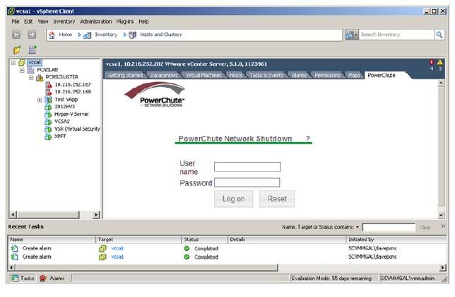
41 PowerChute Network Shutdown: VMware User Guide PowerChute vsphere Plugin Enable the vsphere plug-in option to integrate PowerChute with vcenter Server. The PowerChute vsphere Plugin is available as: 1. a vsphere Client Plugin (vsphere Desktop Client) 2. a vsphere Web Client plugin This can be enabled on the Virtualization Settings page in the PowerChute Setup Wizard or on the Communications Settings page. You can enable only one of the plugin options. To access the vsphere Client plugin: Log into vcenter Server using the vsphere client and access the PowerChute UI using the views below: Home - Management View Home - Inventory - Hosts and Clusters view - select the root level in the left-hand pane and click the PowerChute tab in the right-hand pane. 38
42 VMware Configuration 39


43 PowerChute Network Shutdown: VMware User Guide To access the vsphere Web Client plugin: Log into vcenter Server using the vsphere Web client and access the PowerChute UI by clicking on the Home icon: Home tab - Monitoring Click on the PowerChute icon to log in to PowerChute: The PowerChute vsphere Web Client plugin is only available for vsphere Web Client v5.5 update 1 or later. If Internet Explorer Enhanced Security Configuration is enabled you must add the URL for the machine or VM where PowerChute is installed to the Trusted Sites zone. To do this select Tools-Internet Options in IE and click on the Security tab. Select Trusted Zone and Sites. Add hostname/ip address>:6547 to the list of Trusted Sites. 40

44 VMware Configuration PowerChute vcenter Server Alarms Enabling either of the vsphere plug-in options also creates two custom PowerChute vcenter Server Alarms. In the vsphere desktop client plug-in, both alarms can be configured to carry out actions using the Actions tab in the Alarm Settings dialog. For example you can configure an action to send a notification to an administrator when the alarm is triggered In the vsphere Web Client plugin, both alarms can be configured to carry out actions using the Actions tab - Settings - Manage - Alarm Definitions. 41

45 PowerChute Network Shutdown: VMware User Guide PowerChute UPS Critical Event This alarm will be triggered with Warning status on the Triggered alarms view for the VMware hosts when a critical UPS event occurs and PowerChute starts the shutdown sequence. When PowerChute has finished shutting down VMs and vapps the Alarm status will change to Alert as the VMware hosts are commanded to shut down. PowerChute vcenter Server Authentication Error This alarm will be triggered when PowerChute detects that it can not authenticate with vcenter Server using its existing credentials. Removing Alarms PowerChute vcenter server alarms are removed when: vcenter server plugin is uninstalled vcenter server plugin is disabled The alarms can also be removed manually through vcenter Server. 42
 to the group.")
46 VMware Configuration Active Directory VMware Configuration In the event that vcenter Server is unavailable, it is recommended to configure an Active Directory account that can be used to connect directly to the VMware hosts to perform shutdown actions. 1. In Active Directory Users and Groups create a group called ESX Admins and add your user(s) to the group. When using Active Directory VMware provides a default AD Group account called "ESX Admins". This group is automatically added to each ESXi host joined to the domain and is granted administrator rights by default. 2. Add Active Directory as an Identity Source in VMware Single Sign On using the vsphere Web Client. 3. Log in to vcenter Server using the vsphere Web Client via a browser using default vcenter Server administrator account administrator@vsphere.local. 4. Click on Administration Single Sign On Configuration and then on the Identity Sources tab. 5. Click on the symbol to add a new identity source. 6. Select Active Directory as a LDAP Server. 7. Enter the domain details; e.g. - testdomain.com a. Name: testdomain b. Base DN for Users: CN=Users, DC=testdomain, DC=com c. Domain Name: testdomain.com d. Alias: testdomain e. Base DN for Groups: CN=Users, DC=testdomain, DC=com 43
. 11.")
47 PowerChute Network Shutdown: VMware User Guide f. Primary Server URL: domaincontroller.testdomain.com g. Username: testdomain\domainuser 8. Click OK. 9. Click on Set as default domain. 10. If using vsphere 5.5 and have logged into vsphere Web Client from a Windows machine that is part of the Active Directory domain select Active Directory (Integrated Windows Authentication). 11. Select Use Machine Account. 12. Click OK. 13. Log into vcenter using the vsphere client and select the root folder. 44

48 VMware Configuration 14. Next click on the Permissions tab, right click in the right hand pane and select Add Permission. Change the Assigned Role to Administrator. Click Add under Users and Groups. Select your Active Directory domain from the dropdown list. Select the group ESX Admins and click Add. 15. Click OK. 13. Confirm "Propagate to child objects" is selected. 45

49 PowerChute Network Shutdown: VMware User Guide 14. Click OK again. 15. Select each host in the Inventory and go to Configuration Authentication Services under Software. Click on properties and join the host to your Active Directory Domain. 16. When entering the vcenter Server details in the PowerChute Setup Wizard enter a domain user account that is a member of the ESX Admins Active Directory User group. 17. More information on VMware Single Sign On Configuration is available from the VMware site at: Log in to each VMware Host using the vsphere Client. 19. At the root level in the inventory click on the Permissions tab. 20. Verify that the ESX Admins group is present and has been assigned the Adminstrator role. 46


50 VMware Configuration Shared Local Account for vcenter Server and VMware hosts Create Shared Local Account on vcenter Server 1. In the event that vcenter Server is unavailable a shared account needs to be configured that can be used to connect directly to the VMware hosts to perform shutdown actions. 2. If Active Directory is not available then a local user account can be added to vcenter Server. 3. An account with the same name and password then needs to be added to each ESXi host. 4. Log in to vcenter Server machine and add a user via Computer Management -> Local Users and Groups for Windows. On Linux/vCenter Server Appliance use the terminal commands useradd and passwd. 47
 under domain, select the User that was added in step 4 and click Add. 9. Click OK. 10.")
51 PowerChute Network Shutdown: VMware User Guide 5. Log in to vcenter Server using the vsphere Client and click on the Permissions tab at the root inventory level. 6. Right click and select Add Permission. 7. In the Assign Permissions dialog click Add. 8. Select (server) under domain, select the User that was added in step 4 and click Add. 9. Click OK. 10. Change the Assigned role to Administrator. 11. Select Propagate to Child Objects and Click OK. 48

52 VMware Configuration Shared Local Account for vcenter Server and VMware hosts Create Shared Local Account on each VMware host 1. Log in to each ESXi host using the vsphere client and click on Local Users and Groups tab. 2. Right click and select Add Enter the same username and password that was used when adding the local user to vcenter Server. 4. Click on the Permissions tab. 5. Right click and select Add Permission. 6. In the Assign Permissions dialog click Add. 7. Select (server) under domain, select the User that was added in step 3 and click Add. 8. Click OK. 9. Change the Assigned role to Administrator. 10. Select Propagate to Child Objects and Click OK. A shared local account should be used when vcenter Server is running on a VM and Active Directory is unavailable. A shared local account can also be used if the Active Directory Domain Controller is running on a VM and will be shut down. 49
53 Shutdown Settings The Shutdown Settings page enables you to configure UPS turnoff and the shutdown command files. UPS Shutdown Shutdown Command Files Shutdown settings for Advanced UPS Configurations 50
54 Shutdown Settings UPS Shutdown The default setting is Do not turn off the UPS. You can select Turn off the UPS if you want to preserve battery power. Some UPS s do not support UPS turnoff through PowerChute or the NMC. For these models, it can only be done at the UPS itself. Please check your UPS documentation to ensure your model supports UPS turnoff. If your UPS has Switched Outlet Groups, then the Turn off the UPS Outlet Group option enables you to turn off the outlet group that supplies power to the PowerChute protected server after a critical event occurs. The default behavior for most UPS s if they are turned off following an on-battery shutdown is that they will turn on again once input power is restored. The On-Battery Shutdown Behavior setting can be found in the NMC under Configuration Shutdown where you can change the behavior to Turn off and Stay off if required. Turn Off Single UPS On Battery in a Redundant-UPS Configuration This is not available for an Advanced UPS Configuration that contains UPS Setups with Redundant UPS's. In a Redundant UPS configuration you have the option to turn off one of the UPS s after it has switched to battery power. This is designed to prolong the battery life and preserve the battery power of the UPS. If using this feature on a UPS that supports outlet groups the option "Turn off the UPS" should be enabled. The load is still protected by the other UPS in the configuration. After the specified delay, PowerChute will issue a command to gracefully turn off the UPS. If one UPS is on battery and another UPS switches to battery before the configured delay for Single UPS turn off has elapsed, then the first UPS will not be turned off. If the shutdown action is enabled for the On Battery event, a Multiple Critical event condition will occur if a second UPS switches to battery power (after the first UPS has been commanded to turn off by PowerChute). When this occurs the shutdown sequence will start after 10 seconds. 51
55 PowerChute Network Shutdown: VMware User Guide Shutdown Command Files A Shutdown Command File can be configured to run if a UPS critical event is triggered. Full path to command file: You must specify the full path name of the command file, including the disk drive or volume name. On Windows, the file should be a.cmd or.bat file. For Linux and Unix systems, it should be a.sh file with execute permissions of chmod +x [command file name]. Duration: Enter the number of seconds that the shutdown command file requires to execute. You must determine the time required for your command file to execute. PowerChute cannot determine whether the command file has completed, so it will wait only the amount of time entered before triggering an operating system shutdown. The command file runs using the local system account. For Linux/Unix the command file must be executed with root privileges. PowerChute cannot execute programs that require interaction with the desktop; only command line enabled programs are supported. 52
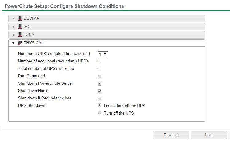
56 Shutdown Settings Shutdown Settings for Advanced UPS Configurations With Advanced UPS configurations, PowerChute can monitor multiple UPS setups, including single UPS devices and groups of redundant UPS devices that you have created (see Advanced UPS Setups ). For each setup, you need to specify the following: Field Number of UPS s required to power load Description Set this value to the minimum number of UPS s that must be available to support the equipment that is being powered by the UPS s in the setup. The value set here will be subtracted from the total number of UPS s in the setup and used to calculate the number of additional (redundant) UPS s. In redundancy terminology, this is the N in N+x. This setting is not displayed for UPS Setups with a Single UPS device. Number of additional (redundant) UPS s This will appear in a setup with more than one UPS. It represents the number of extra UPS s in the setup. This option is associated with the number of UPS critical events required to trigger shutdown: Redundancy level No. of critical events that will trigger a shutdown sequence N+1 2 N+2 3 N+3 4 Multiple critical events occurring on the same UPS does not impact the above table values. In redundancy terminology, this is the x in N+x. This setting is not displayed for UPS Setups with a Single UPS device. Total number of UPS s in Setup Run Command This is the total of the above two rows and is calculated automatically. When a shutdown sequence is triggered you can configure PowerChute to execute a command file. Note: If the same command file is configured for each setup and a shutdown sequence is triggered for more than one setup at the same time, the command file is only executed once. See Shutdown Command Files. 53
57 PowerChute Network Shutdown: VMware User Guide Shut down PowerChute Server This is enabled by default and is used to gracefully shut down the physical machine running PowerChute. This option should be disabled if the PowerChute machine is not being powered by the UPS s in a particular setup, and if it is being used to remotely shut down other servers/ equipment. This option is not available if PowerChute is installed on vma or deployed as a virtual appliance. Shut down if Redundancy lost If this option is enabled, when the number of UPS critical events is the same as the number of additional (redundant) UPS s, a shutdown sequence will be triggered. This option is associated with the number of UPS critical events required to trigger shutdown: Redundancy level No. of critical events that will trigger a shutdown sequence N+1 1 N+2 2 N+3 3 Multiple critical events occurring on the same UPS does not impact the above table values. This option is not shown if there are no additional (redundant) UPS s. For example, this option will not appear if the number of UPS s required to power the load is the same as the total number of UPS s in the group. UPS Shutdown Use this option to set the required UPS behavior after connected servers/equipment have been gracefully shut down. For more information see UPS Shutdown. Execute Virtualization Shutdown Sequence Use this option to trigger the actions enabled on the Virtualization Settings page for ESXi hosts that are linked to UPSs/UPS Setups: VM migration/vm Shutdown/vApp shutdown followed by ESXi host shutdown. This option is available only in a configuration in which a UPS setup is powering something other than a virtual host (e.g. a storage array) - it is enabled by default. 54
58 Event Configuration When UPS events occur, PowerChute can be configured to log the event, notify users, execute a command file or initiate a system shutdown through the Configure Events screen. The symbol indicates that the action is enabled for this event while the symbol indicates that the action is not enabled. Descriptions of events are in the PowerChute Events and Logging sections. 55
59 PowerChute Network Shutdown: VMware User Guide Notifications PowerChute can send a message to one user or all logged-in users when an event occurs: Notify all users: For Windows, the message will be sent to all users who are on the same network. For Linux or Unix, all users who are logged onto the server with a terminal prompt open will be notified. Notify only this user: On Windows, enter the machine name. On Linux or Unix systems, enter the user name. The user will still need to be logged onto the server with a terminal prompt open to be notified. Repeat Interval: The time interval, in seconds, at which the message will be repeated while the event condition exists. If this field is blank or zero, the message will not be repeated. Delay (if required): Enter the amount of time in seconds that PowerChute should wait after the event occurs before notifying users. Users will be notified immediately if a shutdown event is triggered. For Windows operating systems, PowerChute can only send notifications if the operating system supports the messenger service. If not supported, there is no option displayed in the UI. See KBase article FA for more information. (If you have difficulty with this link, enter "FA169440" at 56
60 Event Configuration Event-Driven Command Files If required, PowerChute can be configured to execute a command file after certain events are triggered. Click the symbol on the event row and select the Enable Command File check box. Delay: Enter the amount of time in seconds that PowerChute should wait when the event occurs before executing the command file. If a shutdown command file is also configured, both command files will be executed in parallel. Full path to command file: You must specify the full path name of the command file, including the disk drive or volume name. On Windows, the file should be a.cmd or.bat file. For Linux and Unix systems, it should be a.sh file. The command file runs using the local system account. PowerChute cannot execute programs that require interaction with the desktop; only command line-enabled programs are supported. 57
61 PowerChute Network Shutdown: VMware User Guide Shutdown Actions When the Shutdown Action is enabled for an event, PowerChute treats the event as critical and will trigger a shutdown sequence. Shutdown is not supported for all events: this is indicated by the presence or absence of an icon on the event row. The Delay field is the amount of time in seconds that PowerChute should wait before initiating the shutdown sequence. By default, the On Battery event has a delay of 120 seconds, whereas the default for all other events is 0 seconds. By default, PowerChute will only trigger a shutdown sequence if a low battery condition occurs or the UPS is commanded to turn off. Shutdown cannot be disabled for these events using the PowerChute user interface. 58
62 Sequenced Server Shutdown The Runtime Remaining below Threshold event can be used to sequence the order that your servers shut down during an extended power outage. This is useful if you have multiple servers powered by the same UPS and you want to extend the runtime for your higher priority servers. It also ensures that lower priority servers are the first to be shut down. This event will trigger a server shutdown command when the UPS is running on battery power and the runtime has dropped below the threshold configured. You can also configure a command file to execute before shutdown occurs by specifying a higher runtime threshold value for the Run Command File event action. Example 1. You have 3 servers powered by the same UPS. Your lower priority server is Server C while you want to keep Server A running as long as possible. 2. You want Server A to shut down when the UPS protecting it has 10 minutes runtime remaining. 3. You want Server B to shut down when the UPS protecting it has 15 minutes runtime remaining. 4. You want Server C to shut down when the UPS protecting it has 20 minute runtime remaining. 5. Configure each PowerChute Agent with the following threshold values: o o o Server A 10 minutes Server B - 15 minutes Server C - 20 minutes 6. Each server is shut down when the runtime remaining drops below the threshold configured. 59
63 Sample Shutdown Scenarios The following scenarios provide examples of how PowerChute and the UPS behave when a shutdown sequence is triggered. 60
64 Sample Shutdown Scenarios VMware: UPS without Outlet Groups Example 1: Turn off the UPS enabled, no shutdown command file configured. PowerChute is installed on a physical machine outside the cluster, configured for a Single/Redundant UPS configuration with several VMware Hosts in a HA cluster. The option to Turn off the UPS is enabled on the Shutdown settings page. No shutdown command file is configured. VM shutdown and vapp shutdown have been enabled with 120 second delay configured for each. When a critical UPS event, such as On Battery occurs, the following sequence is triggered. 1. PowerChute reports that the UPS is on battery. 2. After the shutdown delay configured for the On Battery event has elapsed, PowerChute starts a Maintenance mode task on the VMware Hosts and starts to shut down VMs and vapps. 3. After 4 minutes (VM shutdown delay = 120, vapp shutdown delay = 120), PowerChute issues a command to turn off the UPS. UPS turnoff starts. 4. VMware Hosts enter Maintenance mode if all VMs are powered off, otherwise the Maintenance mode task is cancelled. PowerChute issues commands to shut down the VMware hosts. 5. After a 70 second delay the operating system on the physical machine running PowerChute starts to shut down. 6. The UPS will wait the amount of time indicated by one of the following, whichever is greater: Low Battery Duration or Maximum Required Delay. These are shown on the Configuration - Shutdown page in the NMC interface. 7. After this delay, a further non-configurable two minute delay is counted down. 8. The UPS will then turn off after the user-configurable Shutdown Delay time has elapsed This is configurable on the Configuration - Shutdown page in the NMC user interface. 61
65 PowerChute Network Shutdown: VMware User Guide It is recommended that the Low Battery Duration is configured to allow enough time for the Operating System shutdown to complete. Ideally the operating system should have shut down before the non-configurable two minute delay (step 7) starts to count down. Example 2: Turn off the UPS enabled, shutdown command file configured. PowerChute is installed on a physical machine outside the cluster, and configured for a Single/Redundant UPS configuration with several VMware Hosts in a HA cluster. The option to Turn off the UPS is enabled on the Shutdown settings page. A shutdown command file is configured. VM shutdown and vapp shutdown have been enabled with 120 second delay configured for each. When a critical UPS event, such as On Battery occurs, the following sequence is triggered. 1. PowerChute reports that the UPS is on battery. 2. After the shutdown delay configured for the On Battery event has elapsed, starts a Maintenance mode task on the VMware hosts and starts to shut down VMs and vapps. 3. After 4 minutes (VM shutdown delay = 120, vapp shutdown delay = 120), PowerChute starts to execute the shutdown command file and sends a command to turn off the UPS. 4. UPS turnoff starts. 5. VMware hosts enter Maintenance mode if all VMs are powered off, otherwise the Maintenance mode task is cancelled. After the duration configured for the shutdown command file has elapsed, PowerChute issues commands to shut down the VMware hosts. 6. An additional 70 second delay is counted down before the operating system on the physical machine running PowerChute starts to shut down. 7. The UPS will wait the amount of time indicated by one of the following, whichever is greater: Low Battery Duration or Maximum Required Delay. These are shown on the Configuration - Shutdown page in the NMC interface. 8. After this delay, a further non-configurable two minute delay is counted down. 9. The UPS will then turn off after the user-configurable Shutdown Delay time has elapsed. This is configurable on the Configuration - Shutdown page in the NMC user interface. 62
66 Sample Shutdown Scenarios It is recommended that the Low Battery Duration is configured to allow enough time for the Operating System shutdown to complete. Ideally the operating system should have shut down before the non-configurable two minute delay (step 8) starts to count down. 63
67 PowerChute Network Shutdown: VMware User Guide VMware: UPS with Outlet Groups Example 1: Turn off the Outlet Group enabled, no shutdown command file configured. PowerChute is installed on a physical machine outside the cluster, configured for a Single/Redundant UPS configuration with several VMware Hosts in a HA cluster. The option to Turn off the Outlet Group is enabled on the Shutdown settings page. No Shutdown command file is configured. VM shutdown and vapp shutdown have been enabled with 120 second delay configured for each. When a critical UPS event, such as On Battery occurs, the following sequence is triggered. 1. PowerChute reports that the UPS is on battery. 2. After the shutdown delay configured for the On Battery event has elapsed, PowerChute starts a Maintenance mode task on the VMware Hosts and starts to shut down VMs and vapps. 3. After 4 minutes (VM shutdown delay = 120, vapp shutdown delay = 120), PowerChute issues a command to turn off the UPS outlet group and the outlet group turn off starts. 4. VMware Hosts enter Maintenance mode if all VMs are powered off, otherwise the Maintenance mode task is cancelled. PowerChute issues commands to shut down the VMware hosts. 5. VMware hosts enter Maintenance mode if all VMs are powered off, otherwise the Maintenance mode task is cancelled. PowerChute issues the operating system shutdown command. 6. After a 70 second delay, the operating system on the physical machine running PowerChute starts to shut down. 7. The outlet group will turn off after the Power Off Delay (configurable on the Configuration Outlet Group page in the NMC user interface) has elapsed. If registered with the Main Outlet Group, the UPS will wait for any Switched Outlet Groups to turn off before the Main Outlet Group turnoff starts. If registered with a Switched Outlet Group, only that delay is counted down. 64
68 Sample Shutdown Scenarios It is recommended that the outlet group Power Off Delay is configured to allow enough time for the operating system shutdown to complete. You should allow extra time to ensure that the outlet group does not turn off before the operating system. Example 2 : Turn off the Outlet Group enabled, shutdown command file configured. PowerChute is installed on a physical machine outside the cluster, configured for a Single/Redundant UPS configuration with several VMware Hosts in a HA cluster. The option to Turn off the Outlet Group is enabled on the Shutdown settings page. A shutdown command file is configured. VM shutdown and vapp shutdown have been enabled with 120 second delay configured for each. When a critical UPS event, such as On Battery occurs, the following sequence is triggered. 1. PowerChute reports that the UPS is on battery. 2. After the shutdown delay configured for the On Battery event has elapsed, PowerChute starts a Maintenance mode task on the VMware Hosts and starts to shut down VMs and vapps. 3. After 4 minutes (VM shutdown delay = 120, vapp shutdown delay = 120), PowerChute starts to execute the shutdown command file and sends a command to turn off the outlet group. 4. The outlet group turnoff starts. 5. VMware Hosts enter Maintenance mode if all VMs are powered off, otherwise the Maintenance mode task is cancelled. After the duration configured for the shutdown command file has elapsed, PowerChute issues commands to shut down the VMware hosts. 6. An additional 70 second delay is counted down before the operating system starts to shut down. 7. The Outlet Group will turn off after the Power Off Delay (configurable on the Configuration Outlet Group page in the NMC user interface) has elapsed. If registered with the Main Outlet Group, the UPS will wait for any Switched Outlet groups to turn off before the Main Outlet Group turn off starts. If registered with a Switched Outlet Group only that delay is counted down. It is recommended that the outlet group Power Off delay is configured to allow enough time for the shutdown command file and the operating system shutdown to complete. You should allow extra time to ensure that the outlet group does not turn off before the operating system. 65
69 PowerChute Network Shutdown: VMware User Guide Recommended Power-Off Delays for Outlet groups By default, the outlet group Power Off Delay will be the same value as the Low Battery duration configured on the NMC. PowerChute will automatically increase the Power Off Delay for the outlet group it is registered with, if the total shutdown time it needs is greater than the Power Off Delay. The total shutdown time includes the following values: VM Migration delay VM Shutdown and Startup Delays vapp Shutdown and Startup Delays Shutdown Command File Duration Built-in delay of 2 minutes (this consists of a 10 second OS shutdown delay and a 60 second OS shutdown duration; rounded up) The time required to gracefully shut down your operating system is not covered by the total shutdown time, as PowerChute cannot determine how long it will take to complete. The Power Off Delay for the outlet group should be long enough for the OS to gracefully shut down. You should add extra time to allow for unforeseen circumstances. The Low Battery Duration set on the NMC should be equal to or greater than the Power Off Delay for the outlet group. 66

70 Sample Shutdown Scenarios VMware Shutdown - Single UPS Configuration In this example, there are two VMware hosts, a vcenter Server and a storage array being powered by a single UPS. PowerChute is installed on the vcenter Server machine outside the cluster. The following shutdown sequence occurs when the shutdown action is enabled for the On Battery event. 1. The UPS has been running on Battery power for x number of seconds. 2. PowerChute shuts down the VMs on VMware hosts A and B. 3. PowerChute shuts down the vapp if configured. 4. PowerChute runs the shutdown command file and issues a command to turn off the UPS, if configured. 5. After the shutdown command file duration has elapsed, PowerChute starts a maintenance mode task on the VMware hosts. 6. PowerChute shuts down the VMware hosts. 7. PowerChute shuts down the vcenter Server Machine. 67

71 PowerChute Network Shutdown: VMware User Guide VMware Shutdown - HA Cluster In the following examples, a VMware HA Cluster is protected by a Single, Redundant or Parallel UPS configuration. vcenter Server is running on a virtual machine. Recommended Deployment PowerChute can run on a VM in the HA cluster (either installed on the vma or deployed as a virtual appliance) or be installed on a physical Windows machine outside the cluster. The vcenter Server account configured in PowerChute Network Shutdown must have Administrator permissions on vcenter Server and on each of the ESXi hosts being managed by PowerChute. This can be an Active Directory account or a local user account. For more information see Active Directory VMware Configuration. Example 1 : vcenter Server is running on a VM; PowerChute is installed on a physical Windows machine VM & vapp Shutdown enabled with a 120 second delay (i.e. 120 seconds allocated for each action to complete). The option to turn off the UPS or Outlet Group is enabled. A shutdown command file has been configured with a 120 second duration. When a critical UPS event, such as UPS on Battery occurs the following sequence is triggered: Shutdown Sequence 1. PowerChute reports that the UPS is on battery. 2. Shutdown delay for the On Battery event elapses. PowerChute starts a maintenance mode task on each Host and then starts VM shutdown followed by vapp shutdown. 3. VM/vApp shutdown durations elapse. 4. PowerChute gracefully shuts down the vcenter Server VM. 5. vcenter VM shutdown duration elapses. PowerChute starts executing the shutdown command file. 6. At the same time it sends a command to turn off the UPS or Outlet Group. 68
72 Sample Shutdown Scenarios 7. Shutdown command file duration elapses and PowerChute gracefully shuts down the VMware hosts that are not running the vcenter Server VM. 8. PowerChute shuts down the VMware Host running the vcenter Server VM. 9. OS shutdown sequence starts on the PowerChute physical machine. 10. After a 70 second delay the OS starts to shut down. 11. UPS waits for the duration that is greatest of Low Battery Duration/Maximum Required Delay (Non-Outlet Aware UPS's) or the Outlet Group Power Off Delay. 12. UPS turns off after the user-configurable Shutdown Delay time has elapsed or the Outlet Group turns off after the power off Delay elapses. 69
 The option to turn off the UPS or Outlet Group is enabled A shutdown command file has been configured with a 120 second duration When a critical UPS event, such")
73 PowerChute Network Shutdown: VMware User Guide Example 2 : Both vcenter Server and PowerChute are running on Virtual Machines VM & vapp Shutdown enabled with a 120 second delay (i.e. 120 seconds allocated for each action to complete) The option to turn off the UPS or Outlet Group is enabled A shutdown command file has been configured with a 120 second duration When a critical UPS event, such as UPS on Battery occurs the following sequence is triggered: Shutdown Sequence 1. PowerChute reports that the UPS is on battery. 2. Shutdown delay for the On Battery event elapses. PowerChute starts a maintenance mode task on each host and then starts VM shutdown followed by vapp shutdown. 3. VM/vApp shutdown durations elapse. 4. PowerChute gracefully shuts down the vcenter Server VM. 5. vcenter VM shutdown duration elapses. PowerChute starts executing the shutdown command file. 6. At the same time it sends a command to turn off the UPS or Outlet Group. 7. Shutdown command file duration elapses and PowerChute gracefully shuts down the VMware hosts that are not running the vcenter Server or PowerChute VM. 8. PowerChute shuts down the VMware hosts running vcenter Server VM followed by the host running PowerChute VM. Note: The Maintenance mode task is cancelled for the Host running PowerChute so HA can attempt to restart the PowerChute VM when the hosts power back on. 9. UPS waits for the duration that is greatest of Low Battery Duration/Maximum Required Delay Non-Outlet Aware UPS's or the Outlet Group Power Off Delay. 10. UPS turns off after the user-configurable Shutdown Delay time has elapsed or the Outlet Group turns off after the power off Delay elapses. 70
74 Sample Shutdown Scenarios VMware setups with multiple Clusters or Datacenters If PowerChute is deployed as a virtual appliance we recommend deploying one PowerChute Agent per cluster if your setup has multiple clusters. In environments where there are multiple clusters or datacenters you can use one copy of PowerChute installed on a physical Windows machine to monitor your hosts. PowerChute should be installed on multiple machines if the datacenters/clusters contain hosts that are in different geographical locations. 71

75 PowerChute Network Shutdown: VMware User Guide VMware Shutdown - Advanced UPS Configuration Here, separate UPS devices are powering two VMware hosts: the vcenter Server and a storage array. PowerChute is installed on the vcenter Server machine and is monitoring all UPS s. A shutdown command file has been configured for UPS Setup #1 containing UPS #1. Critical event on UPS #4: Option to shut down virtual hosts is enabled for this UPS. VM Migration is not enabled. 1. UPS #4 goes on battery. 2. The UPS Critical event is triggered for the two VMware hosts in the cluster. 3. PowerChute shuts down the VMs on the two VMware hosts. 4. PowerChute shuts down any vapp that is powered on. 5. PowerChute issues a command to gracefully turn off UPS #4, if this has been configured. 6. PowerChute starts a maintenance mode task on the two VMware hosts. 7. PowerChute shuts down the two VMware hosts. 8. As the physical machine is not affected PowerChute continues to run. Critical event on UPS #1: Option to shut down virtual hosts and the physical machine are enabled for this UPS. VM migration is not enabled. 1. UPS #1 goes on battery. 2. A UPS critical event is triggered for the two VMware hosts. 3. PowerChute shuts down the VMs on the two VMware hosts. 4. PowerChute shuts down any vapp that is powered on. 5. The shutdown command file is executed. 6. After the shutdown command file duration has elapsed, PowerChute issues command to gracefully turn off UPS #1, if configured. 72
76 Sample Shutdown Scenarios 7. PowerChute puts the two VMware hosts into maintenance mode. 8. PowerChute shuts down the two VMware hosts. 9. PowerChute shuts down the vcenter Server machine. For detailed information, please view Using PowerChute Network Shutdown in a VMware HA Cluster Application Note here. 73
77 PowerChute Events and Logging The Event Log displays UPS events that affect PowerChute and the load that it is protecting. Not all UPS events are logged. The log is refreshed automatically every 30 seconds. By default, event logging is enabled for all configurable and non-configurable PowerChute events. To disable logging of an event, use the Configure Events screen. The EventLog.txt file is located in the group1 folder where PowerChute is installed. When the file reaches 1000 log entries, the oldest third of the file is deleted is the default value but you can change it using the PowerChute Configuration (INI) File. To completely clear the Event Log, use the Delete Log File button. Use Export Log to download a copy of the Event Log as a text file. 74
78 PowerChute Events and Logging Configurable Events Available runtime has been exceeded For both conditions below, the total shutdown time includes the following durations: VM migration duration VM shutdown and startup duration vapp shutdown and startup duration Shutdown command file duration Built-in duration of 2 minutes (this consists of a 10 second OS shutdown duration and a 60 second OS shutdown duration; rounded up) This event occurs with either of the following conditions: Condition 1. When the total shutdown time required by PowerChute is greater than the Low Battery Duration minus two minutes configured for the UPS. In the event of a low battery condition, PowerChute will not have enough time to complete the shutdown sequence before the UPS powers off. For example, if the total shutdown time required is 3 minutes and Low Battery Duration is 4 minutes, the Available Runtime has been Exceeded event will be triggered. Resolution: Increase the Low Battery Duration value on the NMC using Configure - Shutdown or decrease the shutdown durations being used by PowerChute. Condition 2. When the shutdown duration configured for the UPS On Battery event plus the total shutdown time required by PowerChute is greater than the Runtime Remaining on the UPS minus two minutes. This condition can be caused by having too great a load on the UPS when the battery is fully charged. Resolution: vcenter Server VM shutdown duration 1. Remove some equipment from the UPS to increase the available runtime. 2. Decrease the shutdown duration time for the UPS On Battery event. 3. Decrease the command file execution time using the Shutdown Settings screen. This event is logged and event actions are carried out even if it occurs on a single UPS in a Redundant or Parallel UPS configuration. Available runtime is sufficient The available UPS Runtime/ Low Battery Duration is sufficient for PowerChute to shut down all equipment gracefully. Battery is discharged The UPS battery runtime has fallen below an acceptable range. If there is a power outage, a low battery condition will occur. This can be caused if the UPS has been operating on battery for an extended time period. 75
79 PowerChute Network Shutdown: VMware User Guide If a Battery Recharged event does not occur within four hours, the UPS may not be charging properly, please contact APC Customer Support. Battery has recharged. The battery runtime of the UPS has returned to within an acceptable range. UPS in Bypass due to an internal hardware problem or UPS overload. The UPS has switched to bypass due to an internal hardware problem or because the UPS is overloaded. Manual Bypass started. A user put the UPS into bypass mode using a hardware switch. Maintenance Bypass started. The UPS has switched to bypass and cannot protect the load if a power outage occurs. This is a normal condition if maintenance is being performed on the UPS. If this event occurs when the UPS was not deliberately put into bypass, please contact Customer Support. UPS no longer in Bypass. The UPS is no longer in a bypass state. Bypass switch is not working properly. The bypass contactor is not operating properly. This will prevent the UPS from being placed in bypass or returning from bypass. Please contact Customer Support. Bypass switch has been replaced. The bypass contactor is now operating properly. Communication has been lost while on battery. PowerChute lost communication while the UPS was on battery and cannot detect a Low Battery condition if the power outage continues. Graceful shutdown cannot be guaranteed. This occurs when the UPS is on battery and: The Management Card cannot communicate with the UPS or PowerChute cannot communicate with the Management Card. Management Card cannot communicate with the UPS. Communication between the NMC and the UPS has been lost. Make sure that the NMC is firmly inserted in its slot. This can occur during a firmware upgrade of the NMC. PowerChute cannot communicate with the Management Card. 76
80 PowerChute Events and Logging Network communication between PowerChute and the NMC has been lost. See Network Management Card Troubleshooting. This can occur during a firmware upgrade of the NMC. Communication has been established. Communication has been established between PowerChute and the NMC. UPS has switched to battery power. The UPS has switched to battery operation due to a power outage. If you can t restore power to the UPS, do the following: 1. If there is no general power outage (i.e. if only this UPS has lost input power), check the building wiring and circuit breakers. 2. If this event occurs occasionally and briefly, check to see if equipment on the same electrical circuit as the UPS uses high power periodically. 3. This event can also be caused by poor power quality (i.e. power fluctuation). Decrease the sensitivity of the UPS through the NMC user interface. 4. If the condition persists, contact an electrician to analyze your utility power. Input Power has been restored. The UPS is no longer running on battery power. The load has exceeded the user specified alarm threshold. The load on your UPS has exceeded the maximum load threshold, set in the NMC user interface. Reduce the load on the UPS or upgrade to a device that can support the existing load. The load no longer exceeds the user specified alarm threshold. The load on your UPS is no longer above the load threshold. Minimum redundancy lost. The UPS has too great a load or there are not enough power modules operational to support the desired redundancy. Check to see that all power modules are functioning properly and that the redundancy configuration is correct. If the condition persists, contact Customer Support. Minimum redundancy restored. The UPS can now support the desired redundancy. Parallel redundancy lost. The system has too great a load or there are not enough operational UPS s to support the desired redundancy level. 77
81 PowerChute Network Shutdown: VMware User Guide Check to see that all UPS s are functioning properly and that the redundancy configuration is correct. If the condition persists, contact Customer Support. Parallel redundancy restored. The Parallel UPS system can now support the desired redundancy. Runtime Remaining has dropped below the threshold while on battery. The runtime remaining has dropped below the configured threshold while on battery. You can configure this threshold using the shutdown action on the Configure Events page. When the UPS in running on battery power and the runtime remaining on the UPS drops below the threshold, PowerChute will trigger a shutdown sequence. See Sequenced Server Shutdown for more information. The runtime remaining is now above the configured threshold or input power has been restored. Occurs when the UPS runtime is greater than the user defined threshold or if the UPS is no longer running on battery power. UPS has overheated which can cause damage. The UPS s internal temperature is too high. Make sure that there is at least one inch of clearance around the UPS, and that the UPS ventilation ports are not blocked. If this condition is not resolved quickly, damage may occur to your UPS. UPS is no longer overheated. The UPS s internal temperature has returned to an acceptable level. UPS output overload. The UPS has sensed a load greater than 100 per cent of its rated capacity. Remove attached equipment from the UPS until the condition is corrected. If this condition happens occasionally and briefly, check to see if some equipment connected to the UPS is using high power periodically (e.g. connected laser printers or photocopiers). If the condition persists, contact Customer Support. UPS overload condition has been corrected. A condition that caused the UPS output overload event to occur has been corrected. 78
82 PowerChute Events and Logging Configurable Environmental Events The following events are logged and event actions are carried out even if they occur on a single UPS in a Redundant or Parallel UPS configuration. Ambient Temperature Out Of Range Probe X. The temperature exceeds the threshold configured for the Environmental temperature probe. Ambient Temperature In Range Probe X. The temperature no longer exceeds the threshold configured for the Environmental temperature probe. Humidity out of Range Probe X. The humidity exceeds the threshold configured for the Environmental humidity probe. Humidity In Range Probe X. The humidity no longer exceeds the threshold configured for the Environmental humidity probe. Communication lost with Environmental Monitor. PowerChute has stopped receiving data from the Environmental Monitoring Card or the probe has been removed from the Universal I/O (UIO) port on the NMC. Check to see that the Environmental Monitoring Card is firmly inserted in its slot and has power. Check that environmental monitoring information is accessible through the NMC user interface. If PowerChute cannot communicate with the NMC you will need to correct that problem first. Communication established with the Environmental Monitor. PowerChute Network Shutdown is receiving data from the Environmental Monitoring Card/Probe. Contact X Alarm. One of the environmental input contacts is in a n alarm state. Check in the location being monitored by this contact. Contact X Normal. One of the environmental input contacts has returned to a normal condition. 79
83 PowerChute Network Shutdown: VMware User Guide Non-Configurable Events Three unsuccessful logon attempts detected. Temporarily denying logon attempts from machine with IP <IP address>. There have been three invalid login attempts from a machine with the IP address listed in the event. Further login attempts will be prevented from this machine for two minutes. This is a security measure designed to prevent brute-force login attempts. Username was changed by user [User] from IP address [IP address]. New username is [Username]. The Username has been changed by the user at the specified IP address. This is a security feature to notify the user when the Username has been changed. Password was changed by user [User] from IP address [IP address]. The password has been changed by the user at the specified IP address. This is a security feature to notify the user when the password has been changed. Authentication phrase was changed by user [User] from IP address [IP address]. The authentication phrase has been changed by the user at the specified IP address. This is a security feature to notify the user when the authentication phrase has been changed. Low-battery condition occurred. The runtime remaining on the UPS has dropped below the Low battery duration value while the UPS was on battery. UPS Turn off has been initiated. A graceful shutdown command has been issued to the UPS using the NMC User Interface, the LCD display or by PowerChute. This event is logged for all UPS Configurations. PowerChute Network Shutdown version X started. The PowerChute Web service has been started. Shutdown process started OS name will shut down soon. The operating system has started to shut down in response to a critical UPS event. Error: Outlet Group X is turned off. The outlet group that PowerChute is registered with is turned off. This can indicate that PowerChute is not configured for the correct outlet group. Warning: Outlet Group X is turning off. Selecting this outlet group will shut down your server. 80
84 PowerChute Events and Logging The outlet group that PowerChute is registered with is shutting down. A shutdown sequence will be started as a result. No Outlet Group specified. Using outlet group X. If PowerChute was not registered with an Outlet group during setup it will be automatically registered with the first outlet group on the UPS by default. PowerChute is unable to open TCP port [number]. Check that TCP port [number] is free. PowerChute uses TCP ports 3052 and 6547 for the Web User Interface. This event will be logged if another application is already using either of the above ports. Use the netstat command to identify which process is using these ports or change the values using the PowerChute Configuration File. PowerChute successfully opened TCP port [number]. Indicates that PowerChute has successfully opened the port it requires for the Web UI. PowerChute is unable to open UDP port Check that UDP port 3052 is free. This is required for NMC communication. PowerChute uses UDP port 3052 for communication with the NMC. This event will be logged if another application is already using this port. Use the netstat command to identify which application is using the port. This port cannot be changed. PowerChute successfully opened UDP port PowerChute was able to open the port it needs for NMC communications. Network Communication with address <ip_address> has been lost. Reported when the PowerChute Agent cannot communicate with the Network Management Card over the network. This could be due to a mismatch in security credentials or a network issue. Management Card [ip_address] cannot communicate with the UPS. Reported when the Network Management Card cannot communicate with the UPS. If this issue persists please contact technical support. Connection failed because PowerChute received an untrusted SSL certificate from the NMC This can occur if registering with an NMC that has HTTPS enabled and is using an SSL certificate that is not signed by a trusted root certification authority. To accept the certificate, enable the option "Accept Untrusted SSL Certificates?" on the UPS Details page of the PowerChute Setup Wizard or add the certificate to the PowerChute-keystore. 81
85 PowerChute Network Shutdown: VMware User Guide PowerChute received an untrusted SSL certificate from the NMC Occurs when registering with an NMC that has HTTPS enabled if the SSL cert is not signed by a trusted root certification authority. PowerChute added a Self-Signed Certificate to PowerChute-keystore If the option Accept Untrusted SSL certificates is enabled, PowerChute will automatically add self-signed and untrusted certs to its local keystore. UPS [ip_address] is running on battery power Reported when one UPS goes on battery in a UPS configuration with multiple UPS's. The On Battery UPS has switched to On Line operation. Reported when one UPS in a UPS configuration with multiple UPS's returns to On Line operation. The On Battery UPS turn off process started. UPS / Outlet Group(s) will turn off soon. The advanced option is enabled under UPS Shutdown Settings for a Redundant UPS Configuration and one UPS is on Battery. UPS [ip_address] has turned off. Reported when one UPS turns off in a UPS configuration with multiple UPS's. The turned off UPS has switched to On Line operation. Reported when one UPS turns back on in a UPS configuration with multiple UPS's. Multiple UPS turn offs have been initiated. Reported in a Redundant UPS Configuration. In n+1 redundancy, this is reported when 2 UPS's turn off. In n+2 redundancy, this is reported when 3 UPS's turn off. In n+3 redundancy, this is reported when 4 UPS's turn off. Multiple UPS have turned off. Reported in a Redundant UPS Configuration. In n+1 redundancy, this is reported when 2 UPS's turn off. In n+2 redundancy, this is reported when 3 UPS's turn off. In n+3 redundancy, this is reported when 4 UPS's turn off. 82
86 PowerChute Events and Logging Multiple Critical Events occurred. This occurs in a Redundant or Parallel-Redundant UPS Configuration when two different critical UPS events are active. Parallel-UPS installation not supported at address [ip_address]. One of the UPS devices in a Parallel-UPS configuration has been removed from the Parallel system. Turning off UPS [NMC IP Address]. PowerChute has sent a graceful shutdown command to the UPS. This is logged when a critical event occurs and the option to Turn off the UPS is enabled on the Shutdown settings page. Turning off outlet [Outlet Name] on UPS [NMC IP Address] PowerChute has sent a graceful shutdown command to the UPS Outlet group. This is logged when a critical event occurs and the option to Turn off the UPS Outlet Group is enabled on the Shutdown settings page. 83
87 PowerChute Network Shutdown: VMware User Guide Configuration (INI) File Events The table below lists events that may be logged as a result of manual changes to the PowerChute Configuration File. See PowerChute Configuration File. Before editing the Configuration file manually you should save a backup copy locally. Error: PowerChute cannot find the configuration file or the backup configuration file. Shutting down. PowerChute cannot locate pcsnconfig.ini or pcnsconfig_backup.ini to error.log in the group1 folder where PowerChute is installed. Please re-install PowerChute. If this does not resolve the issue contact APC technical support. Error: The ini file is missing the required [x] section A required section is missing or incorrectly named. Error: The ini file is missing [x] key from section [x]. A required key is missing. Replace the missing key from a backup file. Error: The ini file could not find IP address information in section [x]. NMC IP addresses are missing from the [NetworkManagementCard] section. Error: The ini contains an invalid value for [x] in section [x]. An invalid value is present in the file and no previous good value or default is available in the backup file. Error: The ini contains an invalid value for [x] in section [x]. Using {2} instead. An invalid value is found in the file but a previous valid value or default value is available in the backup file. This should be checked but no further action may be needed. Error: The key [x] in section [x], did not match the supplied regular expression. This can occur if you enter a username value that contains unsupported characters or if you entered a value other than http/https for they key protocol. Error: Could not convert the value of [x] in section [x] to its expected type. This can occur if you enter a non-numeric value where a numeric value is expected for example. Error: Event [x] is enabled for command file execution, but an invalid value for [x] is specified 84
88 PowerChute Events and Logging The command file specified cannot be found. The ini file has entries defined outside of a section. There are extra entries outside of a section that PowerChute does not recognize. These can be deleted. The invalid key [x] should be deleted from section [x] in the ini file. The configuration file contains keys that PowerChute does not recognize. These can be deleted. The ini file has detected duplicate values for [x] in section [x]. When this occurs PowerChute will use the first value and this may result in an incorrect value being used e.g. if you enter 2 values for the HTTP port (80 and 8080), PowerChute will use 80 instead of The invalid section [x] should be removed from the ini file. The configuration file contains a section that PowerChute does not recognize. This can be deleted. Disabling command file execution for event [x] due to bad parameters. Please validate the configuration. This can occur on a Linux/ Unix system if the path to the command file is valid but the file itself does not have execute permissions. Username was changed from [Username 1] to [Username 2] via ini file. This notifies the user that the username has been changed via the ini file, for security purposes. Password was changed via ini file. This notifies the user that the password has been changed via the ini file, for security purposes. Authentication phrase was changed via ini file. This notifies the user that the authentication phrase has been modified via the ini file, for security purposes. 85
89 PowerChute Network Shutdown: VMware User Guide VMware Virtualization Events The events below are non-configurable and relate to virtualization tasks such as VM shutdown. UPS critical event triggered a shutdown sequence on Host [Host] A critical event has occurred on a UPS associated with [Host]. This will trigger a shutdown sequence using the actions configured on the Virtualization Settings page. DRS will attempt to migrate powered on VMs to another host in the cluster. When VM migration is enabled in PowerChute and DRS automation level is set to fully automated, PowerChute starts a maintenance mode task on the host and allows DRS to migrate VMs to available hosts in the cluster. PowerChute will attempt to migrate powered on VMs to another available host. When VM migration is enabled in PowerChute and DRS is disabled, PowerChute migrates VMs to available hosts in the cluster. If using the Custom Target Host migration option PowerChute will attempt to migrate to those target Hosts. Unable to find a suitable host to migrate VMs from Host [Host]. PowerChute could not find any suitable host within the cluster to migrate the VMs from [Host ] to. VMs on Host [Host1] successfully migrated to Host [Host2] A critical event has occurred on a UPS associated with [Host1] and PowerChute has successfully migrated virtual machines to [Host 2] Start maintenance mode:[host]. PowerChute starts a maintenance mode task on the host when a critical UPS event occurs. Maintenance mode task cancelled on Host [Host] as there are still powered on VMs. Please verify that sufficient time has been configured for VM/vApp/VCSA VM shutdown duration. A critical event has occurred on a UPS associated with this host and PowerChute has cancelled the maintenance mode task for [Host] as there are still powered on VMs prior to attempting to shut down the host. Exit maintenance mode: [Host]. PowerChute takes the Host out of maintenance mode when a critical event is resolved and the Host is powered back on.. Migrating VMs on Host [Host] to another available host. A critical event has occurred on a UPS associated with this host and PowerChute is trying to migrate virtual machines to another host. 86
90 PowerChute Events and Logging Migration was not performed because Host [Host] is not part of any cluster. PowerChute could not migrate the VMs on this host because the host is not part of any VMware cluster. Shutting down VMs on Host [Host]. A critical event has occurred on a UPS associated with this host and PowerChute is shutting down its virtual machines. Shutting down Host [Host]. PowerChute is now shutting down the host. Shutting down vapp [vapp]. PowerChute is shutting down the specified vapp. Starting vapp shutdown process. PowerChute is starting to shut down any vapps. No vapp to shutdown on Host [Host]. A critical event has occurred on a UPS associated with [Host]. PowerChute has not found any vapp associated with [Host] to shut down. Powering on VMs on Host [Host]. A critical event has been resolved and a host has restarted. PowerChute is trying to start up the VMs on that host. Powering on vapp [vapp]. A critical event has been resolved and the host has restarted. PowerChute is starting up the specified vapp in the VMware datacenter. No Hosts have been linked with a UPS. PowerChute cannot shut down any Hosts or their VMs if a critical UPS event occurs. PowerChute is advising you to link your VMware hosts to a UPS Setup. See VMware Host Protection. Shutting down physical machine that PowerChute is running on. The PowerChute machine is shutting down. Cannot connect to vcenter Server. PowerChute may not be able to issue commands to Virtual Machines or Hosts. PowerChute cannot connect to vcenter Server over the network. VM Migration and vapp shutdown cannot be performed when this occurs. 87
91 PowerChute Network Shutdown: VMware User Guide vcenter Server authentication error. PowerChute may not be able to issue commands to Virtual Machines or Hosts. PowerChute cannot connect to vcenter Server using its credentials. Check that the username and password entered under vcenter Server Settings are correct. VM Migration and vapp shutdown cannot be performed when this occurs. Cannot connect to host. PowerChute may not be able to issue commands to the Host. PowerChute cannot connect to the host over the network. Host authentication error. PowerChute may not be able to issue commands to the Host. PowerChute cannot connect to the VMware host using its credentials. Check that the username and password entered under vcenter Server Settings are correct. Shutdown Host failed for Host [Host]. A critical event has occurred on a UPS associated with [Host] and PowerChute was unable to shutdown [Host]. Shutting down vcenter Server VM Host [Host]. PowerChute is shutting down the Host containing the vcenter Server VM. Attempting to power on VMs on Host [Host] that did not start. PowerChute could not previously restart VMs on the specified host and is now trying again Attempting to power on vapp [vapp] that did not start. PowerChute could not previously restart a specified vapp and is now trying again. vapp [vapp] will not be shut down as it contains the Virtual Machine running PowerChute. Please remove the PowerChute VM from the vapp. PowerChute will not shut down the specified vapp as PowerChute is installed on a VM in that vapp. The VM running PowerChute must be removed from the vapp. Cannot connect to vcenter Server. PowerChute will not be able to perform VM Migration. PowerChute cannot connect to vcenter Server in order to perform VM Migration during a shutdown sequence. Cannot connect to vcenter Server. PowerChute will not be able to perform vapp Shutdown. PowerChute cannot connect to vcenter Server in order to perform vapp Shut down during a shutdown sequence. 88
92 PowerChute Events and Logging Shutdown sequence is already in progress on VMware hosts. With an Advanced UPS configuration, when critical events occur on UPS Setups at different times, this event indicates that the shutdown is already in progress so it will not be started again. For example: if a critical event occurs on a UPS Setup with VMware Hosts linked and later on a critical event occurs on a Physical UPS setup, the shutdown sequence will not be performed twice, as it is already in progress from the critical event on the first UPS setup. VM/vApp startup is in progress for Host [Host]. PowerChute will wait for the startup delay to elapse before shutdown is triggered. A critical event has triggered a shutdown sequence, however as either a VM or a vapp startup is already in progress, PowerChute will wait for the specified duration to elapse before continuing with the shutdown sequence. See Virtual Machine Shutdown/Startup. vcenter Server is accessible. PowerChute will be able to issue commands to Virtual Machines or Hosts. PowerChute can now connect to the vcenter Server. Host is accessible. PowerChute will be able to issue commands to the host. PowerChute can now connect to the host. UPS critical event [Event]. The specified critical event has been occurred on a UPS. This will trigger a shutdown sequence if not other shutdown sequence is currently active. UPS critical event [Event] resolved. The specified critical event has been resolved. UPS critical event [Event] resolved on Host [Host]. The specified event has been resolved. UPS critical event resolved on Host [Host]. The event has been resolved. HA enabled for cluster [Cluster]. HA will attempt to re-start PowerChute if the Host on which it is running is shut down. This is logged when PowerChute previously detected that HA was disabled. HA disabled for Cluster [Cluster]. PowerChute will not be re-started automatically if the Host on which it is running is shut down. The specified cluster is not a high availability cluster. Because of this, if the host containing PowerChute in this cluster is shut down, PowerChute cannot be restarted automatically. See also HA Admission Control. 89
93 PowerChute Network Shutdown: VMware User Guide vapp [vapp] in datacenter [Datacenter] will not be shut down because one or more VMs are running on a host unaffected by this critical UPS event. This occurs if Force vapp shutdown is disabled. vapp [vapp] in datacenter [Datacenter] will not be shut down. The vapp is already powered off. A critical event caused a shutdown but the specified vapp is already powered off. vapp [vapp] will not be shut down as it contains the vcenter Server VM. Please remove vcenter Server VM from the vapp. PowerChute will not shut down the specified vapp as the vcenter Server VM is installed on a VM in that vapp. The VM running the vcenter Server VM must be removed from the vapp. vcenter Server VM [VM] cannot be gracefully shut down. Please check vcenter Server VM Shutdown duration. PowerChute in unable to gracefully shut down the VM. Check that the VM Shutdown Duration is long enough to allow for VM s to be shut down safely. Shutting down vcenter Server VM [VM]. PowerChute is shutting down the VM running vcenter Server. Attempting to start vcenter Server VM [VM]. PowerChute is attempting to start the VM running vcenter Server. Host(s) [Host1], [Host2] no longer exist. This event is logged when Hosts that PowerChute is configured to protect (via the Host Protection Page) are no longer present in the vcenter Server Inventory. When this occurs the old hosts will be removed and you need to update the PowerChute configuration using the Host Protection page. PowerChute cannot locate the vcenter Server VM in the Inventory. See the troubleshooting section in the Online Help. This event is logged if PowerChute cannot determine which VMware host is running vcenter Server VM. This can indicate a vsphere Configuration issue and will prevent PowerChute from gracefully shutting down the vcenter Server VM. The vcenter Server VM found in the Inventory is powered off. See the troubleshooting section in the Online Help. This event is logged if PowerChute has identified the vcenter Server VM in the inventory but the VM is powered off. This can indicate a vsphere Configuration issue and will prevent PowerChute from gracefully shutting down the vcenter Server VM that PowerChute is configured for. 90
94 PowerChute Events and Logging Critical Events in a Redundant-UPS Configuration This topic does not apply to Advanced Configuration with Advanced UPS Setups. For more information about Critical Events in Advanced UPS Setups, please view the Using PowerChute Network Shutdown in an Advanced Redundant Setup Application Note here. PowerChute Network Shutdown considers all UPS devices in a Redundant configuration as one UPS System. Each UPS must be able to support the entire load itself. PowerChute follows these shutdown rules when it detects critical events: 2 identical critical events (such as Low-Battery Condition Occurred OR UPS turn off has been initiated) occurring in succession on 2 UPS devices cause a shutdown. The shutdown is immediate and no configured delay is counted down. 2 identical user-configured critical events such as UPS On Battery occurring in succession on 2 UPS devices will cause a shutdown. Any configured delay is counted down first. 2 different critical events (such as Low-Battery Condition Occurred and PowerChute cannot communicate with the Management Card ) occurring in succession on 2 UPS devices cause the event called Multiple Critical Events occurred which always leads to a shutdown. Prior to the PowerChute shutdown process starting, a 10-second delay is counted. No configured delay time is counted down. 91
95 PowerChute Network Shutdown: VMware User Guide Critical Events in a Parallel-UPS Configuration In Parallel-UPS configurations, the combined output of several UPS devices support the load. With this setup, PowerChute monitors the load as it changes to determine whether the mode of operation is Parallel Capacity or Parallel Redundant. For example, you are operating in a Parallel Redundant mode (i.e., there are more UPS devices available than are required to provide power to the load) and then you increase the load by adding new servers. PowerChute detects if the mode of operation changes to Parallel Capacity (i.e., all UPS devices in the configuration are now required to provide power to the load). This could cause PowerChute to initiate a shutdown if just one critical event is triggered. Scenario 1: Three 5kVA UPS devices supporting an 8kVA Server Load (Parallel Redundant) In this Parallel Redundant configuration, two or more critical events occurring cause PowerChute to trigger a graceful shutdown of the server(s). PowerChute follows these shutdown rules. 2 identical critical events (such as Low-Battery Condition: Occurred OR UPS turn off has been initiated) occurring in succession on 2 UPS devices cause a shutdown. The shutdown is immediate and no configured delay is counted down. 2 identical user-configured critical events such as UPS: On Battery occurring in succession on 2 UPS devices will cause a shutdown. Any configured delay is counted down first. 2 different critical events (such as Low-Battery Condition: Occurred and PowerChute cannot communicate with the Management Card ) occurring in succession on 2 UPS devices cause the event called Multiple Critical Events occurred which always leads to a shutdown. Prior to the PowerChute shutdown process starting, a 10-second delay is counted. No configured delay time is counted down. Scenario 2: Three 5kVA UPS devices supporting a 13kVA Server Load (Parallel Capacity) In this Parallel Capacity configuration, one critical event triggers a graceful shutdown of the server(s). However, if 2 occur, they have these delays. If 2 identical critical events occur in a parallel capacity configuration, then the event is only reported once and any configured delay is counted down. If 2 different critical events occur, then both events are reported separately and the shortest shutdown delay of the two is counted down. 92
96 General This section contains information on the topics below: Communications Settings PowerChute Agents PowerChute Configuration (INI) File User Interface Session Timeout Check for Updates Customer Support 93
97 PowerChute Network Shutdown: VMware User Guide Communications Settings PowerChute Access HTTPS is enabled by default and provides secure access to the PowerChute user interface. You may change the Protocol to HTTP (unencrypted) and this will come into effect after you restart the PowerChute service. For more information, please see Application Note PowerChute Network Shutdown Security Features Overview here. PowerChute Security The Username and Authentication Phrase are used to authenticate communications between PowerChute and the NMC. Therefore, you must set these values to be the same in both PowerChute and the NMC. In the NMC, the default administrator username and password are both apc. The default authentication phrase is admin user phrase. We recommend that you change the defaults for security reasons. The maximum number of characters for the user name is 10. The authentication phrase must be 15 to 32 ASCII characters. The password specified here is unique to PowerChute. The password length must be 3 to 32 characters and special characters are allowed. Changes to the Username, Password and Authentication Phrase are logged to the event log. For more information see Non-Configurable Events. If you forget your password, see Resetting your PowerChute username or password. If PowerChute is registered with more than one NMC, they should all use the same administrator user name and authentication phrase. Click the Check Details button on the Communications Settings page to validate that the PowerChute settings are the same as the NMC(s). 94
98 General PowerChute Agents The PowerChute Agents page, under the UPS Configuration menu option, lists all PowerChute Agents registered with the same NMC(s). Loading this screen may be slow as PowerChute tries to resolve the host name for each Agent. If the host name cannot be resolved, just the IP address will be displayed. You can click on an IP address to launch the PowerChute user interface for that Agent. A maximum of 50 PowerChute Agents can be registered with a single NMC. For more information, please view Application Note PowerChute Network Shutdown with more than 50 computers here. If you uninstall a PowerChute Agent, its IP address remains registered with the NMC and must be removed manually using the NMC UI. If System Problem Report is displayed when accessing the screen, this is because PowerChute has not received the information it requires from the NMC(s). During normal operation, this can happen due to network traffic. Try the menu selection again in a few minutes. This may also occur if PowerChute cannot establish communication with the NMC. See Network Management Card Troubleshooting. 95
99 PowerChute Network Shutdown: VMware User Guide PowerChute Configuration File PowerChute stores all its settings in a configuration file called pcnsconfig.ini, located in the group1 folder where PowerChute is installed. This file is updated when running the PowerChute Setup and when you make configuration changes through the user interface, e.g. enabling shutdown actions for events. After you have configured one installation of PowerChute with your required settings you can use the pcnsconfig.ini file to apply the same settings to another copy of PowerChute on a different machine. Certain settings such as the localhostaddress or UnicastAddress values in the [Networking] section will need to be edited manually for the target machine. To apply the settings on the target machine: 1. Stop the PowerChute service. 2. Replace the existing copy of pcnsconfig.ini in the group1 folder. 3. Start the PowerChute service. Resetting your PowerChute username or password If you forget your username or password, you can re-set them by editing the pcnsconfig.ini file. In the [NetworkManagementCard] section of the INI file, set the following lines with your new values: username= new user name password= new password Save the file and re-start the PowerChute service. 96
100 General User Interface Session Timeout The PowerChute user interface has a ten minute session timeout by default. Following ten minutes of inactivity, the session will be terminated and the login screen will display to enter the username and password. It is possible to increase or decrease the duration of the session timeout by editing the Web.xml file. To change the session timeout duration: 1. Stop the PowerChute service. 2. Open the folder where the installed files are located, and locate the file at the following location: \group1\comp\http\html\web-inf\web.xml Open the Web.xml file with a text editor. 3. Locate the the <session-config> element, e.g: <session-config> <session-timeout>10</session-timeout> </session-config> 4. The duration value in the <session-timeout> element can be changed. For example to change the timeout to 15 minutes, change the <session-timeout> value to 15, e.g.: <session-config> <session-timeout>15</session-timeout> </session-config> 5. Save the Web.xml file. 6. Start the PowerChute service. The PowerChute UI will now timeout following a period of inactivity that corresponds to the new <session-timeout> value. 97
101 PowerChute Network Shutdown: VMware User Guide Check for Updates The Enable Automatic Updates feature is selected by default and informs you when a new software update is available. When enabled, PowerChute checks for available software updates when the service is started and every seven days after that. You can also check for updates immediately by clicking the Check Now button. When a new software version is released, key details and a link to download the new version are displayed on the Check for Updates screen and logged in the Event Log. You can disable the software update notifications feature on the last screen of the PowerChute Setup wizard or on the Check for Updates page. 98
102 General Customer Support For customer support options, please visit as a starting point. The Knowledge Base there contains detailed troubleshooting information for product issues. You can also browse discussion forums or submit a query using . For country-specific support centers contact details, go to and select your country from the drop-down box list. This lists the contact details for support services you may require. 99
103 Troubleshooting This section contains information on the topics below: Network Management Card Troubleshooting VMware Troubleshooting Browser Troubleshooting 100
104 Troubleshooting Network Management Card Troubleshooting PowerChute does not register with the Network Management Card(s) or PowerChute reports communications lost with the Network Management Card(s): 1. Verify that the Administrator Username and Authentication Phrase are the same for PowerChute and the NMC. 2. Verify that UDP port 3052 is not being blocked by a firewall. 3. Check the IP settings on the PowerChute machine and on the NMC user interface to verify that the default gateway and subnet mask are correct. 4. Check that the IP address of the Network Management Card has not changed after PowerChute was registered with the NMC. To check this, click on the Communications Settings menu item in PowerChute and check that the IP address shown in the Network Management Card section is correct. 5. Verify that there is a network connection between the PowerChute client computer and the Network Management Card. Attempt to access the Network Management Card from the PowerChute client computer, or use the ping utility from the Network Management Card. 6. A PowerChute Network Shutdown client that acquires its IP address through DHCP will lose communications with the Network Management Card when the client renews its DHCP address lease and acquires a different IP address. To resolve this issue,each system using PowerChute Network Shutdown must have a permanent IP address. Reserve IP addresses in the DHCP server by using the MAC address of the clients, so that they never change for the specified machines. The NMC should also have a static IP address. 7. Verify that the PowerChute service is started. If it is already started, stop the service and then restart it again. 8. Update the firmware on the NMC to the latest version which can be downloaded from the APC Web site, or contact Customer Support. 101
105 PowerChute Network Shutdown: VMware User Guide VMware Troubleshooting VM Migration The issues below will prevent VMs from being migrated to other available Hosts. PowerChute does not log migration errors for individual VMs in the Event Log but the error.log file contains additional information. vsphere Errors When performing manual VM Migration PowerChute uses the MigrateVM_Task API function. When there are errors migrating VMs the following appears in the error.log file: VM Migration Error Message -> [Error message] For detailed information: - Click on vsphere API Reference, Expand vsphere API Reference and go to All Methods->MigrateVM_Task. The faults section provides a table outlining the various errors that can occur when attempting to migrate VMs. To troubleshoot individual VMs the logging level can be set to warn instead of error, see section on debug logging. The events below are logged to the Event Log if some or all VMs fail to migrate when there are target hosts available: Failed to migrate all VMs from Host [hostname] Failed to migrate any VMs from Host [hostname] The events below are logged to the error.log file: [VM] failed to migrate to Host [Host] VMware Error message [Fault message] Examples of errors that can occur include: InvalidState: Thrown if the operation cannot be performed because of the virtual machine's current state or the target host's current state. For example, if the virtual machine configuration information is not available or if the target host is disconnected or in maintenance mode. InsufficientResourcesFault: Thrown if this operation would violate a resource usage policy. MigrationFault: Thrown if it is not possible to migrate the virtual machine to the destination host. This is typically due to hosts being incompatible, such as mismatch in network polices or access to networks and datastores. VmConfigFault: Thrown if the virtual machine is not compatible with the destination host. Typically, a specific subclass of this exception is thrown, such as IDEDiskNotSupported. Note: The errors above and descriptions are taken from the vsphere API Reference Guide : 102
106 Troubleshooting There were no available Hosts to migrate VMs to. This will occur if the other Hosts are in Maintenance mode, incompatible or have a UPS critical event active. The event below is written to the PowerChute Event Log: Unable to find a suitable host to migrate VMs from Host: [Host]" There is no communication with vcenter Server and/or there was an Active Directory authentication error. The event below is written to the PowerChute Event Log: Cannot connect to vcenter Server. PowerChute will not be able to perform VM migration." The migration time set in the Duration field was not long enough to allow all VMs to get migrated to another host in the cluster. The error below is written to the PowerChute Event Log: "Insufficient time to migrate all VMs using the VM Migration Duration configured." The error below is written to the PowerChute error.log: "Insufficient time to migrate all VMs using VM Migration Duration" VM Shutdown There is no communication with vcenter Server and/or there was an Active Directory authentication error. The errors below are written to the PowerChute Event Log: Cannot connect to vcenter Server. PowerChute may not be able to issue commands to Virtual Machines or Hosts. vcenter Server authentication error. PowerChute may not be able to issue commands to Virtual Machines or Hosts. When vcenter Server Connection is not available PowerChute will attempt to connect directly to each ESXi host to perform VM shutdown. This requires a shared user account (see section on creating shared user accounts) to be present on each of the ESXi hosts. If PowerChute cannot connect to the ESXi hosts the following exceptions may appear in the error.log: com.vmware.vim25.nopermission com.vmware.vim25.invalidlogin Solution: Verify that the vcenter Server User Account configured in PowerChute can access each of the ESXi hosts by connecting directly to each host using the vsphere client. If the connection fails add the user account to each ESXi host. If the connection is successful verify that the user account has Administrator permissions. 103
107 PowerChute Network Shutdown: VMware User Guide When PowerChute attempts to connect directly to the ESXi hosts it must be able to connect to them using their Fully Qualified Domain Name or IP Address when vcenter Server is no longer available. If there are DNS issues or Hostname resolution issues the following errors appear in the error.log file: VI SDK invoke exception:java.net.connectexception: Connection timed out: connect Solution: Verify that DNS lookups of the ESXi Host FQDN are working from the PowerChute machine using the nslookup command. If nslookup is failing the ESXi hosts can be added to the /etc/hosts file on Linux (PowerChute Appliance/vMA) or C:\Windows\system32\drivers\etc\hosts file on Windows machines. If the only DNS server available is running as a VM on the ESXi hosts being protected then it is necessary to use the hosts file. Alternatively ESXi hosts can be added to vcenter Server using their IP address instead of FQDN. The time set in the Duration field was insufficient to allow VMs to shut down gracefully. The event below is written to the PowerChute Event Log: "Insufficient time to shut down all VMs using the VM Shutdown Duration configured." The event below is written to the PowerChute Error.log: Insufficient time to migrate all VMs using VM Migration Duration VM Startup VMware tools have not been installed. This will cause a hard shutdown of the VM. VMware tools must be installed to perform graceful Guest OS shutdown. VMware Tools status is shown in the summary tab for VMs. The Host had insufficient resources to start the VM, see section on HA Admission Control. The event below is written to the PowerChute Event Log: Attempting to power on VMs on Host [hostname] that did not start. The event below is written to the PowerChute Error.log: VM [VM] Power on failed. The Host is reporting a HA Configuration error When entering and exiting maintenance mode the Host s HA configuration might experience an error and end up in an invalid state. Invalid state will be shown on the Summary tab for the Host in the vsphere client. This will prevent PowerChute from powering on VMs and there will be repeated event log entries indicating that PowerChute is attempting to re-start VMs that failed to start. Solution: 104
108 Troubleshooting Right click on the Host and select Reconfigure for vsphere HA OR Right click on the Host, select Disconnect and then Reconnect vapp Shutdown There is no communication with vcenter Server and/or there was an Active Directory authentication error. The following event appears in the PowerChute Event Log: Cannot connect to vcenter Server. PowerChute will not be able to perform vapp Shutdown. vapp shutdown is not supported if the vcenter Server is unavailable during the shutdown sequence. VMware Tools have not been installed on each VM in the vapp. This is required to perform Guest OS shutdown. If Guest OS shutdown is enabled for a VM in the vapp and VMware Tools are installed this will cause the vapp shutdown task to fail. The Shutdown action in vapp settings is not set to Guest OS shutdown. If the shutdown action is set to Power Off instead of Guest OS Shutdown, VMs in the vapp will not be shut down gracefully. The time you set in the Duration field was not long enough to allow the vapp to shut down gracefully. The event below is written to the PowerChute Event Log: "Insufficient time to shut down vapp using the vapp Shutdown Duration configured." The event below is written to the PowerChute Error Log: "Insufficient time to shut down vapp using the vapp Shutdown Duration" The vapp contains either the PowerChute VM or the vcenter Server VM. vapp shutdown is not supported if either the PowerChute VM or vcenter Server VM are part of a vapp. The events below are written to the PowerChute Event Log: vapp [vapp] will not be shut down as it contains the Virtual Machine running PowerChute. Please remove PowerChute from the vapp. vapp [vapp] will not be shut down as it contains the vcenter Server VM. Please remove vcenter Server VM from the vapp." 105

109 PowerChute Network Shutdown: VMware User Guide PowerChute was unable to shut down a vapp. The event below is written to the PowerChute error.log: [vapp] vapp could not be Powered Off vcenter Server VM Shutdown VMware Tools are not installed and running on the vcenter Server VM This will prevent the VM from being shut down gracefully and it will also prevent PowerChute from identifying the VM as the one running vcenter Server. PowerChute cannot identify the Virtual Machine running vcenter Server using the IP address or hostname configured under vcenter Server Details on the Communications Settings page This can occur if there is a DNS configuration issue i.e. the IP address/hostname cannot be resolved. The event below is written to the PowerChute Event Log: PowerChute cannot locate the vcenter Server VM in the Inventory. Solution: Check that VMware tools are installed and running on the vcenter Server VM Check that the IP address or Hostname/FQDN for vcenter Server Connection in PowerChute matches the IP/Hostname shown on the Summary page for the VM. The vcenter Server VM IP address is being used by another system or there is an old VM with the same static IP address in the vcenter Server inventory even if that VM is powered off. On the Host Protection page ensure that the Host running the vcenter Server VM is marked with the vsphere icon. Using vsphere client vmotion the vcenter Server VM to another host and verify that the Host protection page is updated to reflect this change. 106
PowerChute TM Network Shutdown v3.1. User Guide. VMware
 PowerChute TM Network Shutdown v3.1 User Guide VMware 990-4595A-001 Publication Date: December, 2013 Table of Contents Introduction... 1 UPS Configuration... 2 Network Configuration... 3 UPS Configuration
User Guide. PowerChute Network Shutdown v4.1 Standard D /2015
 User Guide PowerChute Network Shutdown v4.1 Standard 990-4595D-001 07/2015 Schneider Electric Legal Disclaimer The information presented in this manual is not warranted by Schneider Electric to be authoritative,
PowerChute Network Shutdown v4.2 Release Notes
 PowerChute Network Shutdown v4.2 Release Notes The release notes provide important information about PowerChute Network Shutdown (PowerChute), including known software issues and their solutions. For any
PowerChute TM Network Shutdown in Redundant UPS Configurations
 PowerChute TM Network Shutdown in Redundant UPS Configurations By Sarah Jane Hannon ABSTRACT PowerChute TM Network Shutdown software works in conjunction with the UPS Network Management Card to provide
APC APPLICATION NOTE #98
 #98 Using PowerChute TM Network Shutdown in a Redundant-UPS Configuration By Sarah Jane Hannon Abstract PowerChute TM Network Shutdown software works in conjunction with the UPS Network Management Card
SNMP dedicated to ORVALDI Solar Infini
 SNMP dedicated to ORVALDI Solar Infini User s Manual Management Software for Solar Inverter Table of Contents 1. 2. 3. Overview...1 1.1 Introduction...1 1.2 Features...1 1.3 Overlook...1 1.4 Installation
ELD DRIVER GUIDE June 21, 2018
 ELD DRIVER GUIDE June 21, 2018 Contents Getting Started with PrePass ELD...4 Enroll in the PrePass ELD Program... 4 For a Carrier Enroll in the ELD Service... 4 For a Driver Get Driver Login Information...
Fiorano ESB 2007 Oracle Enterprise Gateway Integration Guide
 An Oracle White Paper June 2011 Fiorano ESB 2007 Oracle Enterprise Gateway Integration Guide 1 / 25 Disclaimer The following is intended to outline our general product direction. It is intended for information
GPI (Gas Pump Interface) with Cash Register Express - Integration Manual
 with Cash Register Express - Integration Manual") One Blue Hill Plaza, Second Floor, PO Box 1546 Pearl River, NY 10965 1-800-PC-AMERICA, 1-800-722-6374 (Voice) 845-920-0800 (Fax) 845-920-0880 GPI (Gas Pump Interface) with Cash Register Express - Integration
One Blue Hill Plaza, Second Floor, PO Box 1546 Pearl River, NY 10965 1-800-PC-AMERICA, 1-800-722-6374 (Voice) 845-920-0800 (Fax) 845-920-0880 GPI (Gas Pump Interface) with Cash Register Express - Integration
Cloudprinter.com Integration
 Documentation Cloudprinter.com Integration Page 1/ Cloudprinter.com Integration Description Integrating with a Cloudprinter.com has never been easier. Receiving orders, downloading artwork and signalling
e-track Certified Driver Operating Manual
 e-track Certified Driver Operating Manual Copyright 2016 all rights reserved. Page: Table of Contents System Overview 4 Login 5 Certifying Logs 6 Unidentified Driver Records 8 Requested Edits 9 ECM Link
EPAS Desktop Pro Software User Manual
 Software User Manual Issue 1.10 Contents 1 Introduction 4 1.1 What is EPAS Desktop Pro? 4 1.2 About This Manual 4 1.3 Typographical Conventions 5 1.4 Getting Technical Support 5 2 Getting Started 6 2.1
Installation and Programming Manual Part: Building Network Interface Card Product: 4100ES
 Installation and Programming Manual Part: Building Network Interface Card 4100-6047 Product: 4100ES Cautions and Warnings READ AND SAVE THESE INSTRUCTIONS- Follow the instructions in this installation
Installing Proactive Monitoring for PowerCenter Operations 2.0 HotFix 1 on Solaris
 Installing Proactive Monitoring for PowerCenter Operations 2.0 HotFix 1 on Solaris 2012-2013 Informatica Corporation. No part of this document may be reproduced or transmitted in any form, by any means
Published on Online Documentation for Altium Products (https://www.altium.com/documentation)
") Published on Online Documentation for Altium Products (https://www.altium.com/documentation) Главная > Private License Service Using Altium Documentation Modified by Rob Evans on Feb 14, 2018 Parent page:
Published on Online Documentation for Altium Products (https://www.altium.com/documentation) Главная > Private License Service Using Altium Documentation Modified by Rob Evans on Feb 14, 2018 Parent page:
Vault-based Private License Server
 Vault-based Private License Server Old Content - see latest equivalent Modified by on 13-Sep-2017 For organizations that require their Altium Designer installations to remain offline isolated from the internet
ELD Compliant Driver Operating Manual
 ELD Compliant Driver Operating Manual Copyright 2017 all rights reserved. Page: Table of Contents System Overview 4 Login 5 Certifying Logs 6 Unidentified Driver Records 8 Requested Edits 9 Dashboard 10
Hours of Service ELD Administrator User Guide v3.6
 Hours of Service ELD Administrator User Guide v3.6 Published: Monday, July 16, 2018. 2018 Verizon Connect Inc. HOURS OF SERVICE ADMIN USER GUIDE Contents Introduction... 3 Using WorkPlan as an ELD... 4
Smart-UPS: legendary uninterruptible power. Intelligent, reliable protection for servers and networks
 Smart-UPS: legendary uninterruptible power Intelligent, reliable protection for servers and networks A legacy of reliability Smart-UPS models Smart-UPS management solutions Smart-UPS accessories Maintain
Smart-UPS with APC SmartConnect Maintain business certainty with intelligent network power protection
 Smart-UPS with APC SmartConnect Maintain business certainty with intelligent network power protection The world s most popular network and server UPS APC award-winning Smart-UPS is the most popular UPS
Contents Getting Started with PrePass ELD...4 Starting a Trip...7 During a Trip Co-Driver Features... 14
 UPDATED February 2, 2018 Contents Getting Started with PrePass ELD...4 Enroll in the PrePass ELD Program... 4 For a Carrier Enroll in the ELD Service... 4 For a Driver Get Driver Login Information... 4
JUMO DSM software. PC software for management, configuration, and maintenance of digital sensors. Operating Manual T90Z001K000
 JUMO DSM software PC software for management, configuration, and maintenance of digital sensors Operating Manual 20359900T90Z001K000 V1.00/EN/00661398 Contents 1 Introduction...................................................
User manual Suppliers evaluation process
 User manual Suppliers evaluation process Document status Version Date Main changes Approved to 6 03/10/2014 Add paragraph 3.12 Status of Documents 5 29/09/2014 Indication document types allowed for upload
TomTom WEBFLEET Contents. Let s drive business TM. Release note
 TomTom WEBFLEET 2.17 Release note Contents Extended WEBFLEET Reporting 2 Reporting Diagnostic Trouble Codes 3 Security features 5 Invoice only interface 7 Default trip mode 8 Navigation map information
Quick Reference: Deactivating Vehicles
 Quick Reference: Deactivating Vehicles Due to finishing contract or vehicle rotation, a customer may wish to have certain vehicles removed from the Active Vehicles list. There are various ways to do this
Wallbox Commander. User Guide WBCM-UG-002-EN 1/11
 Wallbox Commander User Guide 1/11 Welcome to Wallbox Congratulations on your purchase of the revolutionary electric vehicle charging system designed with cuttingedge technology to satisfy your daily needs.
1. Introduction Benefits How it works Tachograph Compatiblity Requirements For End Users
 1. Introduction......................................................................... 2 1.1 Benefits........................................................................ 2 1.2 How it works.....................................................................
TESLA VEHICLES PLUG-IN FOR HOMESEER VERSION 1.0.2
 TESLA VEHICLES PLUG-IN FOR HOMESEER VERSION 1.0.2 RELEASE DATE: 1/15/2019 CONTENTS Terms & Conditions... 2 Overview... 3 Installation... 3 System Requirements... 4 Power Management... 4 Configuration...
App Manual Solution Features
 App Manual Solution Features REGISTERING A FLEET Registration form Go to the Registration page: https://fleetpulse.app/register Select the desired language Directs to the Registration Form, where you can
Redbird Insight User Guide
 Redbird Insight User Guide 1 Copyright 2012 Redbird Flight Simulations Contents Welcome... 3 System Requirements... 4 QUICK START GUIDE...5 Video Display... 6 Support Ethernet Port... 7 Insight DVR Application
One Solution You Can Trust!
 Enhanced Vapor Recovery and In-Station Diagnostics One Company One Order One Phone Call One Solution You Can Trust! From the only company who can offer a complete solution! VRM Vapor Recovery Monitoring
Issue 2.0 December EPAS Midi User Manual EPAS35
 Issue 2.0 December 2017 EPAS Midi EPAS35 CONTENTS 1 Introduction 4 1.1 What is EPAS Desktop Pro? 4 1.2 About This Manual 4 1.3 Typographical Conventions 5 1.4 Getting Technical Support 5 2 Getting Started
Smart-UPS: legendary uninterruptible power. Intelligent, reliable protection for servers and networks
 Smart-UPS: legendary uninterruptible power Intelligent, reliable protection for servers and networks A legacy of reliability Smart-UPS models Smart-UPS management solutions Smart-UPS accessories Maintain
User s Manual. Suitable Products: Three phase grid tie inverter with energy storage Three phase off Grid inverter
 SolarPower Pro User s Manual Suitable Products: Three phase grid tie inverter with energy storage Three phase off Grid inverter Management Software for Solar Inverter Table of Contents 1. SolarPower Pro
KNIME Server Workshop
 KNIME Server Workshop KNIME.com AG 2017 KNIME.com AG. All Rights Reserved. Agenda KNIME Products Overview 11:30 11:45 KNIME Analytics Platform Collaboration Extensions Performance Extensions Productivity
Dominion PX TM. Frequently Dominion PX TM Asked Frequently Asked Questions. General Questions
 Frequently Dominion PX TM Asked Frequently Asked s Dominion PX TM General s What is Dominion PX (PX)? Is Raritan new to the rack power distribution unit market? Can the PX be used as a stand-alone device?
Veritas CloudPoint Release Notes. Ubuntu
 Veritas CloudPoint 2.0.2 Release Notes Ubuntu May 2018 Veritas CloudPoint Release Notes Last updated: 2018-05-23 Document version: 2.0.2 Rev 3 Legal Notice Copyright 2018 Veritas Technologies LLC. All
User Guide Electronic Logging Device
 Nero (ELD) On December 16, 2015, the U.S. Department of Transportation ( https://www.transportation.gov/ ) approved the final ruling for the use of s (ELDs) for driver Hours of Service (HOS) and Driver-Vehicle
Advanced User Manual
 Advanced User Manual Banks SpeedBrake For use with Palm Tungsten E2 2004-2005 Chevy/GMC 6.6L (LLY) Turbo-Diesel Pickup THIS MANUAL IS FOR USE WITH KITS 55419 & 55421 Gale Banks Engineering 546 Duggan Avenue
IBM CMM Quick Reference Guide
 IBM CMM Quick Reference Guide Contents Introduction Prerequisites Requirements Components Used CMM Overview CMM Layout Useful CMM Screens Login Screen System Information Screen Event Log Screen Chassis
PF3100 TROUBLESHOOTING SOLUTIONS TO COMMON PROBLEMS. v1.1 Revised Nov 29, 2016
 PF3100 TROUBLESHOOTING SOLUTIONS TO COMMON PROBLEMS v1.1 Revised Table of Contents 1 Common Alarms and Warnings... 1 2 Common Issues... 6 2.1 Communication problems... 6 2.1.1 Controller communication
MetaXpress PowerCore System Installation and User Guide
 MetaXpress PowerCore System Installation and User Guide Version 1 Part Number: 0112-0183 A December 2008 This document is provided to customers who have purchased MDS Analytical Technologies (US) Inc.
Certified Trac Professional VS-1117
 VS-1117 Certification Code VS-1117 Vskills certification for Trac Professional assesses the candidate as per the company s need for issue tracking and also project management. The certification tests the
SolarPower. User Manual. Suitable Products: Three-phase grid-tie inverter with energy storage. Three-phase off-grid inverter
 SolarPower User Manual Suitable Products: Three-phase grid-tie inverter with energy storage Three-phase off-grid inverter Management Software for Solar Inverter Table of Contents 1. SolarPower Overview...
QUICK START GUIDE 199R10546
 QUICK START GUIDE 199R10546 1.0 Overview This contains detailed information on how to use Holley EFI software and perform tuning that is included within the software itself. Once you load the software,
ZT-USB Series User Manual
 ZT-USB Series User Manual Warranty Warning Copyright All products manufactured by ICP DAS are under warranty regarding defective materials for a period of one year, beginning from the date of delivery
SolarPower. User Manual. Suitable Products: Three-phase grid-tie inverter with energy storage. Three-phase off-grid inverter
 SolarPower User Manual Suitable Products: Three-phase grid-tie inverter with energy storage Three-phase off-grid inverter Management Software for Solar Inverter Table of Contents 1. SolarPower Overview...
INSITE Professional INSITE Lite INSITE RSGR. ISL CM850 User's Manual
 INSITE Professional INSITE Lite INSITE RSGR ISL CM850 User's Manual Table of Contents Getting Started...1 What is INSITE...1 Registering INSITE...1 About...1 The Help System...2 Help Window...2 Help Links...2
UAE Ministry of Interior pilot project for RFID-based SCHOOLBUS/STUDENT TRACKING SYSTEM
 UAE Ministry of Interior pilot project for RFID-based SCHOOLBUS/STUDENT TRACKING SYSTEM Safe, secure and verified school bus transportation TECHNOLOGY School bus route tracking and live data transmission
WIRELESS BLOCKAGE MONITOR OPERATOR S MANUAL
 WIRELESS BLOCKAGE MONITOR OPERATOR S MANUAL FOR TECHNICAL SUPPORT: TELEPHONE: (701) 356-9222 E-MAIL: support@intelligentag.com Wireless Blockage Monitor Operator s Guide 2011 2012 Intelligent Agricultural
Acceptance Test Plan. Stake holder: Dawn Gulick Group members:
 Acceptance Test Plan by Advisor: Santiago Ontañón Stake holder: Dawn Gulick Group members: Matt Hinkle (Computer Science) Steven Hershey (Computer Science) Dylan Kenny (Computer Science) Steven Hansen
ICL Three Pump Controller
 ICL Three Pump Controller Pump Operation The number of pumps that the program controls can be selected by enabling only the ones that are currently installed and in service. The enable/disable setting
SI AT A22. English. Printed: Doc-Nr: PUB / / 000 / 01
 SI AT A22 English 1 Information about the documentation 1.1 About this documentation Read this documentation before initial operation or use. This is a prerequisite for safe, trouble-free handling and
Enterprise Network Management System (NMS) Maintenance Release addresses the following issues:
 Maintenance Release addresses the following issues:") Contents 1) Release Summary...1 2) Enhancement Requests...6 3) Important Notes and Known Limitations...7 4) Platforms Supported...9 5) Installation Notes...9 6) Uninstallation Notes...10 1) Release Summary
Contents 1) Release Summary...1 2) Enhancement Requests...6 3) Important Notes and Known Limitations...7 4) Platforms Supported...9 5) Installation Notes...9 6) Uninstallation Notes...10 1) Release Summary
Vanpool Regional Administration
 Vanpool Regional Administration Contents Introduction... 2 Structure and Layout... 2 Make sure you are in the right application... 3 Vanpool Program Configuration... 3 Lookup... 5 Adding a new van... 6
ET9500 BEMS Interface Box Configuration Guide
 ET9500 BEMS Interface Box Configuration Guide APPLICABILITY & EFFECTIVITY Explains how to install and configure ET9500 BEMS Interface Box. The instructions are effective for the above as of August, 2015
SUBARU STARLINK YOUR SUBARU CONNECTED Safety & Security OWNER S MANUAL. Love. It s what makes a Subaru, a Subaru. MY16StarlinkS&S_OMportrait.
 SUBARU STARLINK YOUR SUBARU CONNECTED Safety & Security OWNER S MANUAL 2016 Love. It s what makes a Subaru, a Subaru. MY16StarlinkS&S_OMportrait.indd 1 5/11/15 3:31 PM TM Foreword... 2 Welcome to SUBARU
Tube Bender. Machine Type - Tube Bender
 Tube Bender Machine Type - Tube Bender Tube Bender Control Mach4 Tube Bender Control Manual X15-250-300 Tube Bender Control Manual X15-250-400 Tube Bender Wiring Guide X15-250-300 Tube Bender Control Mach4
for OpenVMS APC Corporate 132 Fairgrounds Road P.O Box 278 West Kingston, RI Tel: (800) 800-4APC or Fax:
 800-4APC or Fax:") for OpenVMS APC Corporate 132 Fairgrounds Road P.O Box 278 West Kingston, RI 02892 Tel: (800) 800-4APC or 401-789-5735 Fax: 401-789-3180 PowerChute License Statement This software is protected by both
for OpenVMS APC Corporate 132 Fairgrounds Road P.O Box 278 West Kingston, RI 02892 Tel: (800) 800-4APC or 401-789-5735 Fax: 401-789-3180 PowerChute License Statement This software is protected by both
There is a Certification menu option that indicates that the mobile APP, mobile device used were self-certified according to federal requirement.
 November 2017 -Rev. 1.17 Driver must carry this document, either on paper or electronically, inside the vehicle ELD - Hours of Service (HOS) Mobile APP - Driver s Guide Booklet INTRODUCTION AND COMPLIANCE
HOS Mobile App Driver s Guide. pg 1
 HOS Mobile App Driver s Guide pg 1 Driver must carry this document, either on paper or electronically, inside the vehicle. Hours of Service (HOS) Mobile APP Driver s Guide Booklet pg 2 Contents Introduction
ZoneTouch V2 Zone Control System Installation Manual
 ZoneTouch V2 Zone Control System Installation Manual www.polyaire.com.au 2014 Polyaire Pty Ltd TABLE OF CONTENTS 1) Application 2 2) Features 2 3) Components 3 4) Configuration 4 5) Pre-Installation 6
R11B EN R11A EN. RackCDU. Service Manual. Edition August 2016 Page 1 of 24 V /8
 R11B-1528-02EN R11A-0555-03EN Service Manual - English RackCDU Service Manual Edition August 2016 Page 1 of 24 Version history Issue number Reason for update 1.0 / December 2015 Initial release 2.0 / February
V 2.0. Version 9 PC. Setup Guide. Revised:
 V 2.0 Version 9 PC Setup Guide Revised: 06-12-00 Digital 328 v2 and Cakewalk Version 9 PC Contents 1 Introduction 2 2 Configuring Cakewalk 4 3 328 Instrument Definition 6 4 328 Automation Setup 8 5 Automation
CurveMaker DFS v2.0 Dyna FS Ignition Programming Software
 CurveMaker DFS v2.0 Dyna FS Ignition Programming Software Contents Dynatek 164 S. Valencia St. Glendora, CA 91741 phone (626)963-1669 fax (626)963-7399 page 1) Installation 1 2) Overview 1 3) Introduction
Note: If anything is damaged or missing, contact your customer representative immediately.
 Package Contents The package includes: 1 Chassis 1-18 leafs according to the amount ordered 18 - X leaf blanks X = the amount ordered 1 leaf fan module 1 spine fan module 9 spines 1-2 management modules
Installation and User Manual. with RAIN SENSOR.
 with RAIN SENSOR www.solarsmartopener.com Revision..0 TABLE OF CONTENTS Features In The Box Further Items Required Basic Operation Solar Panel and Operator Installation Operator Installation Solar Panel
Cboe Futures Exchange Multicast Depth of Book (PITCH) Implementation Guide. Version 1.0.1
 Implementation Guide. Version 1.0.1") Multicast Depth of Book (PITCH) Implementation Guide Version 1.0.1 October 17, 2017 Contents 1 Introduction... 3 1.1 Overview... 3 1.2 Feed Connectivity Requirements... 3 1.3 Symbol Ranges, Units, and
Multicast Depth of Book (PITCH) Implementation Guide Version 1.0.1 October 17, 2017 Contents 1 Introduction... 3 1.1 Overview... 3 1.2 Feed Connectivity Requirements... 3 1.3 Symbol Ranges, Units, and
SI AT A22. English. Printed: Doc-Nr: PUB / / 000 / 03
 SI AT A22 English 1 Information about the documentation 1.1 About this documentation Read this documentation before initial operation or use. This is a prerequisite for safe, trouble-free handling and
User Manual WatchPower App
 User Manual WatchPower App Management Software for Inverter Table of Contents 1. Introduction... 1 2. WatchPower App Install and Uninstall... 1 2.1. System Requirement... 1 2.2. Software Install... 1 2.3.
Allen-Bradley. User Manual for 8000/10000 VA UPS. Tower/Rack-Mount 6U Uninterruptible Power Supply
 Allen-Bradley User Manual for 8000/10000 VA UPS 1609-P8000E 1609-P10000E 8000 VA 200-240 VAC 10000 VA 200240 VAC Tower/Rack-Mount 6U Uninterruptible Power Supply 41063-261-01(1) 990-2672 09/2005 INSTALLATION
Disclaimer This presentation may contain product features that are currently under development. This overview of new technology represents no commitme
 STO1479BU vsan Beyond the Basics Sumit Lahiri Product Line Manager Eric Knauft Staff Engineer #VMworld #STO1479BU Disclaimer This presentation may contain product features that are currently under development.
SRM 7.0 Detailed Requisitioning
 SRM 7.0 Detailed Requisitioning Rev. October 2014 Course Number: V001 Welcome! Thank you for taking time to complete this course. 1 MENU Course Navigation You can navigate through this course using the
Network Installation. July 2008 CONTENTS
 Network Installation CONTENTS General Software Hard Lock System Requirements Installation on Server Installation on Each Work Station Directory Structure July 2008 Require PowerCad-5 Ver 5.0.72.0 PowerCad-5
CLA-VAL e-drive-34. User Manual. Motorised Pilots. CLA-VAL Europe LIN072UE - 04/16
 User Manual CLA-VAL Europe www.cla-val.ch cla-val@cla-val.ch 1 - LIN072UE - 04/16 Table of Contents 1 Introduction... 3 1.1 Precautions Before Starting... 3 1.2 Troubleshooting... 3 1.3 General Disclaimer...
Motor Vehicle Processing
 Motor Vehicle Processing Each year the DMV distributes a motor vehicle file to each community for taxation. Vision prepares these files for processing in the Tax Administration system. Detailed instructions
Multi Wheel Bluetooth Tire Pressure Monitoring System User Manual Model: External
 T P M S Multi Wheel Bluetooth Tire Pressure Monitoring System User Manual Model: External Table of Contents 1. PRODUCT INTRODUCTION... 2 2. NOTICE... 2 3. BLE TPMS SPECIFICATION... 3 4. BLE TPMS PACKAGE...
Document Version Abbra_
 Congratulations on your purchase of the Abbra Professional Series home security system! With an Abbra system installed in your home, you can rest secure in the knowledge that your home and family are protected.
Customer User Guide. ComTrac CUSTOMER USER GUIDE VERSION 0.1
 Customer User Guide ComTrac CUSTOMER USER GUIDE VERSION 0.1 Contents 1 How to use this guide... 3 1.1 Confidentiality... 3 1.2 Purpose of this guide... 3 1.3 What s new and what s changed... 3 1.4 User
User Manual Solar Charge Controller 3KW
 User Manual Solar Charge Controller 3KW Version: 1.3 CONTENTS 1 ABOUT THIS MANUAL... 1 1.1 Purpose... 1 1.2 Scope... 1 1.3 SAFETY INSTRUCTIONS... 1 2 INTRODUCTION... 2 2.1 Features... 2 2.2 Product Overview...
Pilot document v1 Jan Fleet Manager User Guide
 Pilot document v1 Jan 2015 Fleet Manager User Guide Thank you for taking out RSA Smart Fleet. In the following guide we are going to explain how to use your Fleet Manager Portal. This guide assumes you
Quick Setup Guide. WARNING! Connect this product to an AC power source whose voltage is within the range specified on the product's nameplate.
 Thank you for purchasing the Raritan PX intelligent power distribution unit (PDU). The intended use of the Raritan PX is distribution of power to information technology equipment such as computers and
Process Control System PCS 7 FOUNDATION Fieldbus
 Security information 1 Introduction 2 Basics of the FOUNDATION Fieldbus 3 Process Control System PCS 7 Commissioning Manual System planning 4 Engineering 5 Commissioning 6 Redundancy and system changes
T P M S. Multi Wheel Bluetooth. Tire Pressure Monitoring System. User Manual. Model: External
 T P M S Multi Wheel Bluetooth Tire Pressure Monitoring System User Manual Model: External Table of Contents 1. PRODUCT INTRODUCTION... 2 2. NOTICE... 2 3. BLE TPMS SPECIFICATION... 3 4. BLE TPMS PACKAGE...
NO PART OF THIS DOCUMENT MAY BE REPRODUCED WITHOUT PRIOR AGREEMENT AND WRITTEN PERMISSION OF FORD PERFORMANCE PARTS.
 Table of Contents Table of Contents... 1 Getting Started... 2 ProCal Flash Tool... 2 Verify Package Contents... 2 Getting to Know the ProCal 3 Software... 3 Prepare Vehicle for Flashing... 7 Download Calibration
Vehicle Disabling Systems
 Vehicle Disabling Systems Objective Vehicle disabling systems are used to prevent unauthorized users from initially operating a vehicle and to gradually decelerate and stop a vehicle in-transit under certain
Smart-UPS On-Line Lithium-ion UPS 230V
 Smart-UPS On-Line Lithium-ion UPS 230V Single-phase, rack/tower convertible, double conversion on-line UPS with Li-ion batteries and advanced management features A UPS developed for availability of your
CurveMaker HD v1.0 2Ki Programmable Ignition programming software
 Contents CurveMaker HD v1.0 2Ki Programmable Ignition programming software Dynatek 164 S. Valencia St. Glendora, CA 91741 phone (626)963-1669 fax (626)963-7399 page 1) Installation 1 2) Overview 1 3) Programming
SIMATIC. Process Control System PCS 7 FOUNDATION Fieldbus. Introduction 1. Basics of the FOUNDATION Fieldbus 2. System planning 3.
 Introduction 1 Basics of the FOUNDATION Fieldbus 2 SIMATIC Process Control System PCS 7 Commissioning Manual System planning 3 Engineering 4 Commissioning 5 Redundancy and system changes in operation 6
(If this step is missed, then OBD software is not going to work. So it's CRUCIAL that you follow below steps).
.") How to Install ELM327 USB/Bluetooth on Mac and OBD Software Posted by Alex (Im) E. on 28 January 2013 02:53 AM This article will guide you on how to install ELM327 USB Cable / Bluetooth scanner on your
How to Install ELM327 USB/Bluetooth on Mac and OBD Software Posted by Alex (Im) E. on 28 January 2013 02:53 AM This article will guide you on how to install ELM327 USB Cable / Bluetooth scanner on your
FieldMaster Logs. Administration and Best Practice Guide. Version 3.0 Revision A November 2017 TRANSFORMING THE WAY THE WORLD WORKS
 FieldMaster Logs Administration and Best Practice Guide Version 3.0 Revision A November 2017 TRANSFORMING THE WAY THE WORLD WORKS Legal Notices Trimble Inc. 10368 Westmoor Drive Westminster CO 80021 USA
USER S GUIDE LandAirSea 7100 Real Time GPS Tracking System
 USER S GUIDE LandAirSea 7100 Real Time GPS Tracking System 1.1 Introduction The LandAirSea 7100 is a web-based real time tracking system that uses GPS technology to accurately determine the exact location
EMS Web App User Manual Vehicle Rentals
 DEPARTMENT OF PUBLIC SAFETY Updated on 1/11/18 EMS Web App User Manual Vehicle Rentals This is a user manual for the EMS Web App (formerly VEMS). The EMS Web App is the online component of the desktop
ELD System. Fleet Manager Administrative Portal. User Guide
 ELD System Fleet Manager Administrative Portal User Guide Updated December 5, 2017 Contents Administration (Admin) Portal... 3 Fleet Manager... 3 Account Login... 3 Driver Users... 3 Add a New Driver...
2016 Reporting Guide W Sharp Avenue, Spokane, WA POOL (7665)
") 2016 Reporting Guide 1212 W Sharp Avenue, Spokane, WA 99201 STAvanpool@spokanetransit.com 509-326-POOL (7665) May 2016 Table of Contents Thank You Bookkeepers... 2 On-line Reporting for mileage & Ridership...
2016 Reporting Guide 1212 W Sharp Avenue, Spokane, WA 99201 STAvanpool@spokanetransit.com 509-326-POOL (7665) May 2016 Table of Contents Thank You Bookkeepers... 2 On-line Reporting for mileage & Ridership...
Technical Information
 Technical Service 2/14 ENU WE02 9 WE02 - Re-programming Instrument Cluster (Workshop Campaign) Important Note: CRITICAL WARNING - THIS CAMPAIGN INCLUDES STEPS WHERE SEVERAL CONTROL UNITS IN THE VEHICLE
Vehicle Use Case Task Force E: General Registration & Enrollment Process
 Document History Revision History Revision Number Revision Date Revision/ Reviewed By Summary of Changes Changes marked Approvals This document requires the following approvals. Name Title 1.1 Use Case
SIMATIC. Process Control System PCS 7 FOUNDATION Fieldbus. Introduction 1. Basics of the FOUNDATION Fieldbus 2. System planning 3.
 Introduction 1 Basics of the FOUNDATION Fieldbus 2 SIMATIC Process Control System PCS 7 Commissioning Manual System planning 3 Engineering 4 Commissioning 5 Redundancy and system changes in operation 6
Frequently Asked Questions: EMC Captiva 7.5
 Frequently Asked Questions: EMC Captiva 7.5 Table of Contents What s New? Captiva Web Client Capture REST Services Migration/Upgrades Deprecated Modules Other Changes More Information What s New? Question:
Planting. Press to Highlight Configuration. Gauge Wheel Load Alarm. Value must be entered for your specific planter and parallel arm combination
 To create a configuration, make the following button presses to start the Configuration Wizard and then follow the instructions given on the display. Planting Start of Configuration Wizard Enter Settings