Proto. Document Rev: 1
|
|
|
- Loren Harrison
- 5 years ago
- Views:
Transcription

1 Document Rev: 1
2 Contents Licensing... 3 Source Code, Files & 3D Models... 3 How can I contribute?... 3 Disclaimer... 3 About Your Kit... 4 Introduction... 4 Cosmoneer Kit Contents... 4 Applies to Note... 4 Tools Needed... 5 Using Your Kit... 6 Getting Started... 6 Simulating a Satellite in Space... 7 Summary... 7 Architecture... 7 Subsystems... 8 Product Features & Specifications... 9 Overall... 9 Cosmoneer Motherboard... 9 Control Moment Gyro Assembly... 9 Storage Sphere... 9 Wireless Power Module... 9 Schematic PCB Pin Map & Jumper Settings Guarantee, Warranty & Returns Policy Satisfaction Guarantee Product Warranty Returns Policy... 12
3 Licensing This work is licensed under the Creative Commons Attribution-ShareAlike 4.0 Unported License and the Open Source Hardware (OSHW) Definition 1.0. Source Code, Files & 3D Models The Cosmoneer Rev 01 project is located here: How can I contribute? Depending on your skills, you may consider the following: PCB design work was performed using open source KiCad EDA Software Suite. 3D modeling was performed using Rhino 3D 3D printing was performed using 3D System s 3 rd Generation Cube 3D (no longer sold) Arduino Programming was initially performed using Arduino IDE v1.5.2, now using Please visit for more information and downloads. Disclaimer This kit is provided AS IS and with all faults. Cosmos Pioneering disclaims all other warranties, expressed or implied, regarding products, including but not limited to, any implied warranties of merchantability or fitness for a particular purpose. Please see our product warranty at the end of this product manual for information regarding a defective product.


 Cosmoneer specification (1) Cosmoneer (1)")
 Storage shell (1) Serial IrDa")
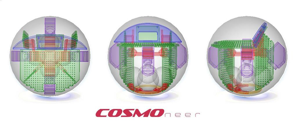
4 About Your Kit Introduction The is a desktop satellite simulator, designed to expose you to many of the challenges spacecraft face while stationed in orbit or floating in space. Your project kit is licensed through open hardware and open software licensing because we believe in the sharing of knowledge! You kit was hand built in the USA. We hope you enjoy it! If you have any questions or problems, please visit our website or send us an . Thanks! Cosmoneer Kit Contents Your kit contains the following: Product manual (this document) Cosmoneer specification (1) Cosmoneer (1) Zero-G simulator stand (1) 12V Wall wart power supply (1) USB cable & FTDI programmer (1) Storage shell (1) Serial IrDa communications board Applies to Note This document applies to the Rev 02 only.
 The appropriate sketch (revision specific via download) A level surface 120V AC power outlet Ideas and suggestions For other code options, visit the user")
5 Tools Needed In order to get the most from your kit, you will need: A computer with the Arduino IDE installed (version or higher) The appropriate sketch (revision specific via download) A level surface 120V AC power outlet Ideas and suggestions For other code options, visit the user community at:
, and then follow these setup steps: 1. Wind the string in a counter-clockwise direction onto the spool, leaving 3-4 of string between the spool and the Cosmoneer.")

6 Using Your Kit Getting Started Setting Everything Up Once you have everything unpacked and laid out, follow the assembly instructions ( and then follow these setup steps: 1. Wind the string in a counter-clockwise direction onto the spool, leaving 3-4 of string between the spool and the Cosmoneer. Insert the spool's peg into the top of the stand. 2. Maneuver the string onto the guide channel at the front edge of the stand so the string and hook dangle over the center of the coil. 3. Firmly grasp the Cosmoneer and hang it from the hook. 4. Place 2-4 USA pennies (or equivalent) in each counterweight holder on the rear of the unit until the coil of the Cosmoneer appears level and is closely ceneter over the stand's Tx coil. 5. Slowly twist the spool so the Cosmoneer rests approximately 1-2 mm from the TX power coil on the Zero-G stand. 6. Connect the power supply to the ZeroG stand. 7. Once the SuperBurst Battery Replacer Board has fully charged, a green LED will illuminate. Your Cosmoneer should begin to boot up and will initiate it's start-up sequence. 8. The will test its compass calibration and execute a calibration routine for your physical location if it is unable to successfully compelte a rotation. Once completed, it will begin its preprogrammed command sequence. Uploading Code When you are ready to write your own code for the Cosmoneer, plug your programming cable into the 's programming port, which is the white connector just above the servo under the main pcb.
7 Simulating a Satellite in Space Summary Generally speaking, space begins at 100km, otherwise known as the Kármán line, and Low Earth Orbit (LEO) is considered to lie between 160km and 2,000km. Orbiting spacecraft reside in Low Earth Orbit (or LEO) in order to avoid drag-inducing atmosphere that slows them down until they fall back to Earth. To simulate this same environment., we use low cost materials, wireless power and 3D printed parts. LEO on a shoe-string budget! Cube satellites, the inspiration for the Cosmoneer, rarely have an independent guidance system to control its attitude. Some tumble, others use Earth s magnetic field, even fewer use fixed spinning wheels and rarely do they use gimbaled control moment gyros. Using simple hobby electronics, we recreated the more advance control moment gyro system. A high speed flywheel (or gyro) is coupled with a servo (gimbal) to provide rotational torque in the Yaw Axis, similar to turning your head left and right. In order to operate in space, nearly all spacecraft rely on solar energy, a form of wireless power. Using a matched pair of wire coils, we transmit power from the Zero-G stand to the Cosmoneer, providing a very close resemblance to solar power. Satellites are power limited in that they can only harness so much power via its fixed solar array. The is similarly limited in how much power it can consume via the wireless link. Architecture All spacecraft designs tend to incorporate at the very least these basic systems: Command & Control, Power, Attitude Control and Communications. Using low cost components, the Cosmoneer incorporates all of these systems at a very simple level. Building on the Arduino architecture, serial infrared communications and the I2C bus, the is able to further simulate the simple electronic systems built into early spacecraft. In fact, most cell phones have more computing power than many spacecraft in orbit. Veering away from the cubesat standard, the is housed in a spherical volume instead of a cube shape. While this increases complexity, it makes possible the ability to simulate a full three degrees of freedom (3DOF) in future versions. Since the system is completely wireless and any communications require a line of sight link, audio and visual feedback are used to provide system status messages. Similar to tones used by some interplanetary spacecraft to denote the progression of descent stages during periods of near radio silence, our tones provide quick informational feedback as to what is happening right then. Satellites tend to use light sensors to locate the sun and the earth to insure they are pointing in the right direction. Interplanetary spacecraft use asteroids and some stars to determine their location in space. The Cosmoneer depends on the Earth s magnetic field to calculate its heading.
8 Subsystems Command & Control Microcontroller Used to sensing and controlling every aspect of the Cosmoneer. Communications System Status LED Used for simple user feedback from the MCU itself. Perimeter LEDs Controlled by 8 of the 16 individual PWM channels, 8 LEDs provide at a glance visual feedback. Piezo Speaker A single piezo element provides audio feedback. Serial IrDA An infrared transceiver and a serial IrDA protocol chip provide a solid communications protocol that can be initiated between Cosmoneer s, or a and a ground-based station. Attitude Control Three Axis Compass/Magnetometer Using the Yaw axis, directional heading values can be obtained. Control Moment Gyro A Servo, Gyro motor and brushless motor speed controller used to provide inertial guidance. Power Wireless Power Transmitter and Receiver Used to simulate solar energy, Wireless power not only provides energy to function, but also provides a method to stay energized while remaining near friction-less.

, 0.1 sec/60deg(4.8v), 4.2-6v input Brushless Motor 5.")
9 Product Features & Specifications Overall All detailed Mfg spec sheets can be found here. Cosmoneer Motherboard Micro Controller Atmega328p-au, 5V, 16Mhz Compass Honeywell HMC5883L, 3.3V Serial IrDA MCP2120-SL & TFBS4711, 5V 16ch PWM Controller PCA9685, 5V Control Moment Gyro Assembly 5g Micro Servo 0.6kg torque (8 oz/in), 0.1 sec/60deg(4.8v), 4.2-6v input Brushless Motor 5.5v 3 phase Motor Controller MX-3A ESC Storage Sphere Acrylic Sphere 100mm OD, 97mm ID Wireless Power Module
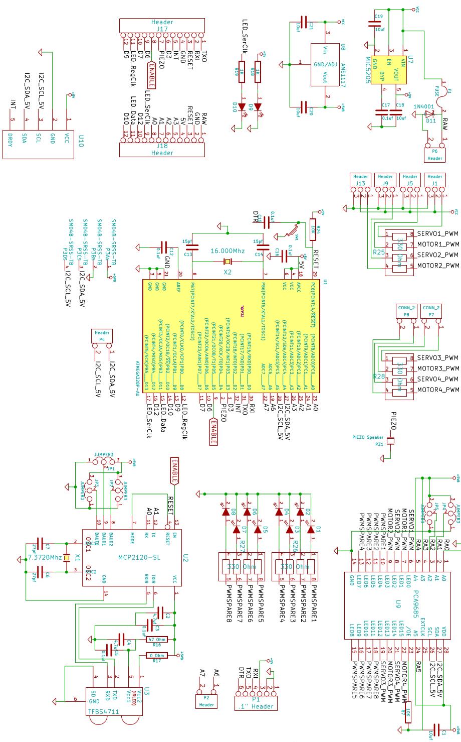
10 Schematic
11 PCB Pin Map & Jumper Settings User Configurable Jumper Settings MCP2120 Baud Rate Jumper Settings - Users may adjust jumper profiles to configure specific Cosmoneer settings. WARNING! Please insure the center jumper does not bridge the two outer jumpers, else a power to ground short will result! PCA9685 I2C Address Jumper Settings - Jumpers adhere to the following rule: =0 RA0-RA5 00(1111) Address =1 JP4(RA0) (Default) 0x7C JP5(RA1) RA0-RA5 01(1111) Address JP4 - Jumpers adhere to the following rules: JP1 (B1) =1 =0 JP2(B2) & JP3(B0) =0 =1 B0-B2 000 Baud 9600 JP1 (Default) B0-B2 100 Baud JP1 B0-B2 010 Baud JP1 0x7D JP RA0-RA5 10(1111) Address JP4 B0-B2 110 Baud JP1 JP1 JP RA0-RA5 11(1111) Address JP4 B0-B2 001 Baud 0x7F JP JP2 JP3 JP x7E JP3 JP3 JP2 JP3 JP2 JP3 JP2 NOTE: These baud rates coincide with the use of an external Mhz crystal (clock source).
12 Guarantee, Warranty & Returns Policy Satisfaction Guarantee If for any reason you re not 100% satisfied with your Cosmoneer kit in the first 30 days, just return the entire kit and we ll refund the entire product price. No questions asked. Product Warranty This Warranty covers any defects in material or workmanship of your Cosmoneer under normal use during the Warranty Period. During the Warranty Period, Cosmos Pioneering will repair or replace, at no charge, products or parts of a product that proves defective because of improper material or workmanship, under normal use and maintenance. The Warranty Period for this kit is 90 days from the date of purchase. A replacement kit or part assumes the remaining warranty of the original part, or 90 days from the date of replacement or repair, whichever is longer. This Warranty does not cover any problem that is caused by conditions, malfunctions or damage not resulting from defects in material or workmanship To obtain warranty service, contact us to determine the problem and the appropriate solution for you. Returns Policy In order to return your Cosmoneer, all kit contents must be returned, along with the original packing slip. Unless your kit is approved for return and an RMA number has been issued, the customer will be responsible for return shipping costs. Returns Process Please call or us to obtain an RMA number and return shipping address for defective products. Pack your unit as best as possible to avoid additional damage. Contact Cosmos Pioneering Phone: cosmoneer@cosmospioneering.com 3D Printable Replacement Parts
Warning! Before continuing further, please ensure that you have NOT mounted the propellers on the MultiRotor.
 Mission Planner Setup ( optional, do not use if you have already completed the Dashboard set-up ) Warning! Before continuing further, please ensure that you have NOT mounted the propellers on the MultiRotor.
Begin to Use The New ESC: Before use the new ESC please carefully check every connections are correct or not. Yellow motor wire B Blue motor wire A
 HIMOTO ZTW Brushless Electronic Speed Control for car or truck Thank you for purchasing ZTW Brushless Electronic Speed Controller(ESC). The ZTW electronic speed control (ESC) is specifically designed for
ZT-USB Series User Manual
 ZT-USB Series User Manual Warranty Warning Copyright All products manufactured by ICP DAS are under warranty regarding defective materials for a period of one year, beginning from the date of delivery
IDL Dragonfly Manual
 2015 IDL-20003 Dragonfly Manual FIRMWARE VERSION 3.00 IRIS DYNAMICS LTD. IDL-20003 Manual IrisDynamics.com V1.00 December, 2015 IDL-20003 Manual IrisDynamics.com V1.00 December, 2015 Unpacking, Setup,
APPLICATION NOTE. ATAK51003-V1 Quick Start Guide. Atmel ATAN0033. Kit Contents
 APPLICATION NOTE ATAK51003-V1 Quick Start Guide Atmel ATAN0033 Kit Contents The Atmel ATAK51003-V1 Kit includes the following components: 1 Atmel ATAB5279-V1.2 LF antenna driver 2 LF antenna modules 1
DMR Series User Guide
 1 INTRODUCTION DMR Series User Guide This manual provides instructions on incorporating your Castle Creations DMR (Dedicated Multi-Rotor) ESCs into your aircraft, from wiring and mounting your ESCs to
INTECH Micro 2300-RTD6
 INTECH Micro 2300-RTD6 6 Channel RTD Input Station Overview. The Intech Micro 2300 Series is a system of modular I/O Remote Stations, that add an even lower cost option to Intech s already extensive intelligent
CP Data Sheet I-CAM Introduction: I-CAM, Integrated Calibration And Automated Mapping CP Engineering Systems Ltd.
 I-CAM Introduction: I-CAM, Integrated Calibration And Automated Mapping as a component add-on to the advanced CADET V12 Engine and Vehicle Test System, provides a state-of-the-art, automatic engine spark
ELG4126: Case Study 2 Hybrid System Design and Installation
 ELG4126: Case Study 2 Hybrid System Design and Installation Diesel Driven Generator Life Cycle Costing Photovoltaic Cells, Modules, and Arrays Possibility of Integrating Fuel Cells and Wind Turbines Environmental
DPD72001, DPD Unipolar Step Motor Driver. User s Guide E. Landon Drive Anaheim, CA
 DPD72001, DPD72002 Unipolar Step Motor Driver User s Guide A N A H E I M A U T O M A T I O N 4985 E. Landon Drive Anaheim, CA 92807 e-mail: info@anaheimautomation.com (714) 992-6990 fax: (714) 992-0471
SMARTSat. Shape Memory Alloy Research Technology Satellite. Allison Barnard Alicia Broederdorf. Texas A&M University Space Engineering Institute
 SMARTSat Shape Memory Alloy Research Technology Satellite Allison Barnard Alicia Broederdorf Texas A&M University Space Engineering Institute Outline Introduction / Mission Objectives Systems Overview
1.0 Features and Description
 1.0 Features and Description The is an intelligent actuator designed for precise control of quarter turn valves and dampers. Using stepper motor technology, the SmartStep proportionally positions valves
T H E U L T I M A T E L A S E R D E F E N S E S Y S T E M
 S P E E D O F L I G H T P R O T E C T I O N CINCINNATI MICROWAVE 5440 West Chester Road West Chester OH 45069 Sales/Service 800-433-3487 EscortRadar.com 2014 CINCINNATI MICROWAVE. ESCORT, Laser ShifterPro,
FC151. FC151 Flight Control System Instruction Manual. #21436
 Shanghai Dualsky Models co.,ltd. Rm.1016,No.201,Xin Jin Qiao Rd.,Shanghai,China. Tel: +86 21 50322162 Fax: +86 21 50322163 Flight Control System Instruction Manual Made in China 41ZX15F0810 #21436 http://www.dualsky.com
2006 Manual. Manual Version: R2.1 Last Update:
 2006 Manual Manual Version: R2.1 Last Update: 04.03.06 Introduction Congratulations on your purchase of the ACT LABS RS Shifter 2006. One of the great tactile pleasures of driving a fine sports car is
(Designed & Manufactured by RC EXPLORER TEAM) Radon V2 series Brushless Speed Control System User Guidelines
 Radon V2 series Brushless Speed Control System User Guidelines") (Designed & Manufactured by RC EXPLORER TEAM) Radon V2 series Brushless Speed Control System User Guidelines 1. Technical /Specifications: Model: Radon Pro V2 Radon Pro V2 1S Radon Sport V2 Continuous
(Designed & Manufactured by RC EXPLORER TEAM) Radon V2 series Brushless Speed Control System User Guidelines 1. Technical /Specifications: Model: Radon Pro V2 Radon Pro V2 1S Radon Sport V2 Continuous
Week 11. Module 5: EE100 Course Project Making your first robot
 Week 11 Module 5: EE100 Course Project Making your first robot Dr. Ing. Ahmad Kamal Nasir Office Hours: Room 9-245A Tuesday (1000-1100) Wednesday (1500-1600) Course Project: Wall-Follower Robot Week 1
OpenEVSE - 40A Charging Station
 OpenEVSE - 40A Charging Station P50 Advanced P50 Standard http://www.openevse.com Read and save these instructions prior to installing and operating your Charging Station. Retain this installation guide
Issue 2.0 December EPAS Midi User Manual EPAS35
 Issue 2.0 December 2017 EPAS Midi EPAS35 CONTENTS 1 Introduction 4 1.1 What is EPAS Desktop Pro? 4 1.2 About This Manual 4 1.3 Typographical Conventions 5 1.4 Getting Technical Support 5 2 Getting Started
Multi-Rotor Series User Guide
 1 INTRODUCTION Multi-Rotor Series User Guide This manual provides instructions on incorporating your Castle Creations Multi-Rotor ESCs into your aircraft, from wiring and mounting your ESCs to configuring
L I M I T E D L I F E T I M E W A R R A N T Y
 L I M I T E D L I F E T I M E W A R R A N T Y Products manufactured and sold by OMEGA RESEARCH & DEVELOPMENT, INC. (the Company), are warranted to be free from defects in materials and workmanship under
ilevil 2 AW Wireless Integrated Avionics Module AD-AHRS, GPS, ADS-B 978 / 1090 MHz Receiver Instruction Manual
 ilevil 2 AW Wireless Integrated Avionics Module AD-AHRS, GPS, ADS-B 978 / 1090 MHz Receiver Instruction Manual ilevil 2 AW ADS-B ANTENNA GPS ANTENNA STATIC PRESSURE DYNAMIC PRESSURE ON/OFF SWITCH CHARGING
Operation Manual 3-Axis Stabilization System for Fixed Wing Model Aircraft
 Operation Manual -Axis Stabilization System for Fixed Wing Model Aircraft Table of Contents Introduction 2 Safety Instructions 2 Product Layout 2 HGXA Overview 2 LED Display Overview Specifications Features
Hi-Z USB Wireless. Introduction/Welcome
 Hi-Z USB Wireless Introduction/Welcome Thank you for selecting the Hi-Z Antennas USB Wireless system. The Hi-Z USB Wireless system provides control functions from a personal computer to operate a Hi-Z
PHOENIX HV Features of the Phoenix HV-45 : 2.3 Connecting the Motor. 2.4 Reversing Rotation. 2.5 Connecting the Receiver
 PHOENIX HV -45 1.0 Features of the Phoenix HV-45 : Extremely Low Resistance (.003 ohms) High rate adjustable switching (PWM) Up to 45 Amps continuous current Dual Opto-Coupled (No BEC) Up to 36 cells or
Energy Harvesting Platform
 Energy Harvesting Platform Group 8 S A N JAY K H E ML A NI T R AV I S B A D A L L K I A R A R O D R I G U EZ M I C H A EL L I N EE EE EE EE Motivation Non-renewable energy sources harm the environment
Thank you for buying an Alien Power System (APS) product. WARNING: Product Features:
 product. WARNING: Product Features:") Thank you for buying an Alien Power System (APS) product. Please follow the instructions to program your controller. Incorrect handling may cause damage to the controller and cause injury to yourself and
Thank you for buying an Alien Power System (APS) product. Please follow the instructions to program your controller. Incorrect handling may cause damage to the controller and cause injury to yourself and
N-03 STEERING GEAR CONTROL SYSTEMS
 Guideline No.: N-03(201510) N-03 STEERING GEAR CONTROL SYSTEMS Issued date: October 20,2015 China Classification Society Foreword: This Guideline is a part of CCS Rules, which contains technical requirements,
Installation and Operation Guide
 Bus-Scan CR2 RF Installation and Operation Guide All Content and Information are Copyright 2018 Robotics Technologies, Inc. Features and Information are subject to change without notice. All Rights Reserved.
DIAGNOSIS AND TESTING
 206-09-1 Vehicle Dynamic Systems 206-09-1 DIAGNOSIS AND TESTING Anti-Lock Control Traction Control and Stability Assist Special Tool(s) Principles of Operation 73III Automotive Meter 105-R0057 or equivalent
DPBHV001, DPZHV002. High Voltage Step Motor Driver. User s Guide. (714) fax: (714) website:
 fax: (714) website:") DPBHV001, DPZHV002 High Voltage Step Motor Driver User s Guide A N A H E I M A U T O M A T I O N 910 East Orangefair Lane, Anaheim, CA 92801 e-mail: info@anaheimautomation.com (714) 992-6990 fax: (714)
DPBHV001, DPZHV002 High Voltage Step Motor Driver User s Guide A N A H E I M A U T O M A T I O N 910 East Orangefair Lane, Anaheim, CA 92801 e-mail: info@anaheimautomation.com (714) 992-6990 fax: (714)
(Designed & Manufactured by RC EXPLORER TEAM) XPS Brushless Speed Control System User Guidelines
 XPS Brushless Speed Control System User Guidelines") (Designed & Manufactured by RC EXPLORER TEAM) XPS Brushless Speed Control System User Guidelines 1. Technical /Specifications: Model: XPS- Pro XPS-Sport XPS-EL Continuous current: 140A 70A 35A Burst Current
(Designed & Manufactured by RC EXPLORER TEAM) XPS Brushless Speed Control System User Guidelines 1. Technical /Specifications: Model: XPS- Pro XPS-Sport XPS-EL Continuous current: 140A 70A 35A Burst Current
CENTROIDTM. AC Brushless Drive. Product Spec Sheet
 4 Axis, up to 2 KW motors Brake Output for each axis Overtemp and Overcurrent Protection All-software Configuration Self-cooled Fiber Optic Control CENTROIDTM AC Brushless Drive Product Spec Sheet AC Brushless
Welcome to VBar Express 5.3
 Bar Express Welcome to VBar Express 5.3 The VBar with V 5.3 Express software is an innovative product setting new standards for model helicopters in terms of flight performance and programming capacity.
Orion BMS Purchasing Guide Rev. 1.2
 www.orionbms.com Orion BMS Purchasing Guide Rev. 1.2 Main Components... 2 Orion BMS Unit... 2 Current Sensor... 4 Thermistors... 5 CANdapter... 6 Wiring Harnesses... 7 Cell voltage tap wiring harnesses...
DPS32001 and DPS32PS1
 DPS32001 and DPS32PS1 Driver Pack User s Guide A N A H E I M A U T O M A T I O N 4985 E. Landon Drive Anaheim, CA 92807 e-mail: info@anaheimautomation.com (714) 992-6990 fax: (714) 992-0471 website: www.anaheimautomation.com
PHOENIX Features of the Phoenix-25 : 2.3 Connecting the Motor. 2.4 Reversing Rotation. 2.5 Connecting the Receiver
 Warning! High power motor systems can be very dangerous! High currents can heat wires and batteries, causing fires and burning skin. Follow the wiring directions carefully! Model aircraft equipped with
Emergency Response Trailer 14
 Emergency Response Trailer 14 User & Genave / NRC, Inc. www.genave.com support@genave.com Copyright 2017. Genave / NRC, Inc. Tech. Publication No. 9000-0000-115 Rev 01 Warning If incorrectly used, this
HYDROS Development of a CubeSat Water Electrolysis Propulsion System
 HYDROS Development of a CubeSat Water Electrolysis Propulsion System Vince Ethier, Lenny Paritsky, Todd Moser, Jeffrey Slostad, Robert Hoyt Tethers Unlimited, Inc 11711 N. Creek Pkwy S., Suite D113, Bothell,
RS485 board. EB062
 RS485 board www.matrixmultimedia.com EB062 Contents About this document 3 Board layout 3 General information 4 Circuit description 4 Protective cover 5 Circuit diagram 6 2 Copyright About this document
OMOTENASHI. (Outstanding MOon exploration TEchnologies demonstrated by NAno Semi-Hard Impactor)
") SLS EM-1 secondary payload OMOTENASHI (Outstanding MOon exploration TEchnologies demonstrated by NAno Semi-Hard Impactor) The smallest moon lander launched by the most powerful rocket in the world * Omotenashi
SLS EM-1 secondary payload OMOTENASHI (Outstanding MOon exploration TEchnologies demonstrated by NAno Semi-Hard Impactor) The smallest moon lander launched by the most powerful rocket in the world * Omotenashi
MSD Boost Control Module PN 7763
 MSD Boost Control Module PN 7763 ONLINE PRODUCT REGISTRATION: Register your MSD product online. Registering your product will help if there is ever a warranty issue with your product and helps the MSD
Formation Flying Experiments on the Orion-Emerald Mission. Introduction
 Formation Flying Experiments on the Orion-Emerald Mission Philip Ferguson Jonathan P. How Space Systems Lab Massachusetts Institute of Technology Present updated Orion mission operations Goals & timelines
Openness Design modularity Outstanding Quality Fine positioning INGENIA MOTION CONTROL Motor control Engineered Solutions Complete Integration
 Openness Design modularity Outstanding Quality Fine positioning INGENIA MOTION CONTROL Motor control Engineered Solutions Complete Integration Freedom to create Complete motion control Your partner in
Quick Start Guide. Three-phase brushless DC motor driver expansion board based on L6230 for STM32 Nucleo (X-NUCLEO-IHM07M1)
") Quick Start Guide Three-phase brushless DC motor driver expansion board based on L6230 for STM32 Nucleo (X-NUCLEO-IHM07M1) Version 1.0 (September 18, 2015) Overview 2 1 Introduction to the STM32 Open Development
Quick Start Guide Three-phase brushless DC motor driver expansion board based on L6230 for STM32 Nucleo (X-NUCLEO-IHM07M1) Version 1.0 (September 18, 2015) Overview 2 1 Introduction to the STM32 Open Development
Project Narrative Description
 0 Project Narrative Description Charge Spot is intended to demonstrate the feasibility of an autonomous electric vehicle charging system for residential use. The goal of Charge Spot is to have no user
AFP MEA Mini Electrical Rotary Actuator User s Instructions
 AFP MEA Mini Electrical Rotary Actuator User s Instructions Please read and understand the instruction related to this product. These are User s Instructions and the AN-05 application notes. WARNING Failure
Product Guide: Series III Pump Control Board Set (RoHS)
") revised 04/08/10 Description: The Series III Pump Control Board Set provides motor drive and pump control for a wide assortment of pumps from Scientific Systems, Inc. The assembly consists of two circuit
revised 04/08/10 Description: The Series III Pump Control Board Set provides motor drive and pump control for a wide assortment of pumps from Scientific Systems, Inc. The assembly consists of two circuit
Quick Start Guide. Three-phase brushless DC motor driver expansion board based on L6230 for STM32 Nucleo (X-NUCLEO-IHM07M1)
") Quick Start Guide Three-phase brushless DC motor driver expansion board based on L6230 for STM32 Nucleo (X-NUCLEO-IHM07M1) Version 1.1.0 (May 16, 2016) Quick Start Guide Contents 2 X-NUCLEO-IHM07M1: Three-phase
Quick Start Guide Three-phase brushless DC motor driver expansion board based on L6230 for STM32 Nucleo (X-NUCLEO-IHM07M1) Version 1.1.0 (May 16, 2016) Quick Start Guide Contents 2 X-NUCLEO-IHM07M1: Three-phase
When you finish the running, power off the receiver BEFORE turning off the transmitter.
 Thanks for purchasing Turnigy AQUASTAR ESC speed controllers. Turnigy AQUASTAR ESC are specifically developed to supply stable and strong power for r/c model boats beyond you expected. Please read the
BIM-17-2 Bus Interface Module for compass and outside temperature
 BIM-17-2 Bus Interface Module for compass and outside temperature Mount the temperature sensor in the front grill area or another location that can get good air flow while the vehicle is being driven.
ELM327 OBD to RS232 Interpreter
 OBD to RS232 Interpreter Description Almost all new automobiles produced today are required, by law, to provide an interface from which test equipment can obtain diagnostic information. The data transfer
IAQ-CALC INDOOR AIR QUALITY METER MODEL 7515
 IAQ-CALC INDOOR AIR QUALITY METER MODEL 7515 OPERATION AND SERVICE MANUAL P/N 1980571, REVISION D FEBRUARY 2016 Copyright TSI Incorporated / May 2007-2016 / All rights reserved. Address TSI Incorporated
MD10. Engine Controller. Installation and User Manual for the MD10 Engine Controller. Full Version
 MD10 Engine Controller Installation and User Manual for the MD10 Engine Controller. Full Version File: MartinMD10rev1.4.doc May 16, 2002 2 READ MANUAL BEFORE INSTALLING UNIT Receipt of shipment and warranty
Freescale Semiconductor, I
 M68HC08 Microcontrollers 8-Bit Software Development Kit for Motor Control Targeting the MC68HC908MR32 SDKMR32UG/D Rev. 1, 11/2002 MOTOROLA.COM/SEMICONDUCTORS 8-Bit Software Development Kit for Motor Control
PRODUCT INFORMATION BULLETIN
 724-283-4681 724-283-5939 (fax) PRODUCT INFORMATION BULLETIN DESCRIPTION The, Model 10-7100 is one in a series of critical speed switches that monitor speed and detect motion in all types of machinery
Cirtix series Brushless Speed Controller manual For RS1/RS A/ Page - 1 -
 RS1/RS20602010A/100524 Page - 1 - Thank you for purchasing the Speed Passion Cirtix series electronic speed controller (ESC). High power systems for RC models can be very dangerous, so we strongly suggest
INSTALLATION MANUAL HARLEY-DAVIDSON V-ROD DESTROYER DATA ACQUISITION SYSTEM (Part Number 200-KT-V300D)
") INSTALLATION MANUAL HARLEY-DAVIDSON V-ROD DESTROYER DATA ACQUISITION SYSTEM (Part Number 200-KT-V300D) The Racepak data acquisition system you have purchased for your Harley-Davidson Destroyer has been
INSTALLATION MANUAL HARLEY-DAVIDSON V-ROD DESTROYER DATA ACQUISITION SYSTEM (Part Number 200-KT-V300D) The Racepak data acquisition system you have purchased for your Harley-Davidson Destroyer has been
FOR SERVICE SEND TO: AUTO METER PRODUCTS, INC. 413 W. Elm St., Sycamore, IL USA (815) us at
 us at") 2650-887F INSTALLATION INSTRUCTIONS 5 single channel ultimate tach COPYRIGHT PATENT 5 4 6 3 PENDING 7 8 PLAYBACK 9 2 0 1 AUTO METER PRODUCTS, INC. SYCAMORE, IL USA MADE R P M X1000 IN USA ENTER START PAUSE
2650-887F INSTALLATION INSTRUCTIONS 5 single channel ultimate tach COPYRIGHT PATENT 5 4 6 3 PENDING 7 8 PLAYBACK 9 2 0 1 AUTO METER PRODUCTS, INC. SYCAMORE, IL USA MADE R P M X1000 IN USA ENTER START PAUSE
DJI E800 Multirotor Propulsion System
 DJI E800 Multirotor Propulsion System User Manual V1.0 2015.01 Disclaimer Thank you for purchasing the E800 (hereinafter referred to as product ). Read this disclaimer carefully before using this product.
Chroma-Q Junior FX Gobo Rotators Twin FX Gobo Rotators
 Chroma-Q Junior FX Gobo Rotators Twin FX Gobo Rotators User Manual Version 1.0 September 2012 PN: 146-0500 Warranty Statement Chroma-Q warrants to the original purchaser, with proof of purchase, that its
INSTALLATION INSTRUCTIONS 5" SINGLE CHANNEL ULTIMATE TACH
 Instr. No. 2650-887D INSTALLATION INSTRUCTIONS 5" SINGLE CHANNEL ULTIMATE TACH IMPORTANT WEAR SAFETY GLASSES 5 4 6 COPYRIGHT PATENT PENDING 3 7 8 PLAYBACK 9 2 0 1 AUTO METER PRODUCTS, INC. SYCAMORE, IL
DJI E1200 Standard. Tuned Propulsion System. User Manual V
 DJI E1200 Standard Tuned Propulsion System User Manual V1.2 2015.8 Disclaimer Thank you for purchasing the E1200 Standard Tuned Propulsion System (hereinafter referred to as product ). Read this disclaimer
Plain-Talk Plain-Talk Plus Plain-Talk with Steering Wheel Control
 Installation and Users Guide BMW E46 3-Series Parrot harness adapter kit Version 1.05 Plain-Talk Plain-Talk Plus Plain-Talk with Steering Wheel Control This product covers all E46 3 series vehicles produced
Section 55 Chapter 6
 Section 55 Chapter 6 REMOTE HYDRAULICS CONTROLLER Calibration and Fault Codes 6-12880NH TABLE OF CONTENTS REMOTE HYDRAULICS CONTROLLER CALIBRATION... 55-5 Requirements For Calibration... 55-5 Aux Set Main
DC motor theory. Resources and methods for learning about these subjects (list a few here, in preparation for your research):
:") DC motor theory This worksheet and all related files are licensed under the Creative Commons Attribution License, version 1.0. To view a copy of this license, visit http://creativecommons.org/licenses/by/1.0/,
DC motor theory This worksheet and all related files are licensed under the Creative Commons Attribution License, version 1.0. To view a copy of this license, visit http://creativecommons.org/licenses/by/1.0/,
TM4500. Track Mounted Step Motor Driver. User s Guide. CE Certified and RoHS Compliant #L010060
 TM4500 Track Mounted Step Motor Driver User s Guide CE Certified and RoHS Compliant A N A H E I M A U T O M A T I O N 4985 E. Landon Drive Anaheim, CA 92807 e-mail: info@anaheimautomation.com (714) 992-6990
PHOENIX Features of the Phoenix-10 : 2.3 Connecting the Motor. 2.4 Reversing Rotation. 2.5 Connecting the Receiver
 Warning! High power motor systems can be very dangerous! High currents can heat wires and batteries, causing fires and burning skin. Follow the wiring directions carefully! Model aircraft equipped with
SHORT-STOP. Electronic Motor Brake Type G. Instructions and Setup Manual
 Electronic Motor Brake Type G Instructions and Setup Manual Table of Contents Table of Contents Electronic Motor Brake Type G... 1 1. INTRODUCTION... 2 2. DESCRIPTION AND APPLICATIONS... 2 3. SAFETY NOTES...
Quantumfire QF cue Wireless Remote Firing System
 Quantumfire QF-24 24 cue Wireless Remote Firing System Thank you for purchasing the Quantumfire QF-24 firing system. This is by far the best amateur firing system on the market today. Quantumfire QF-24
ELM327 OBD to RS232 Interpreter
 OBD to RS232 Interpreter Description Almost all new automobiles produced today are required, by law, to provide an interface from which test equipment can obtain diagnostic information. The data transfer
Audio Operator Interface Installation Instructions
 Audio Operator Interface Installation Instructions Introduction This publication describes the installation procedure for the following: 4100-1243 Microphone 4100-1244 Remote Microphone 4100-1252 Audio
MPT-250B SPECIFICATIONS AND OPERATING INSTRUCTIONS
 1. SAFETY The MPT-250B Wire Crimp Pull Tester is a force measurement device, and as such should be operated with due caution. Operators should wear safety glasses for eye protection because the crimp under
INSTALLATION MANUAL AND OPERATING INSTRUCTIONS Electric Attitude Indicator
 INSTALLATION MANUAL AND OPERATING INSTRUCTIONS 4200-21 Electric Attitude Indicator Mid-Continent Instruments and Avionics Manual Number 9016182-1 9400 E 34 th Street N, Wichita, KS 67226 USA Revision D,
Application Note. First trip test. A circuit breaker spends most of its lifetime conducting current without any
 Application Note First trip test A circuit breaker spends most of its lifetime conducting current without any operation. Once the protective relay detects a problem, the breaker that was idle for maybe
Solar Dock Post Lites
 12 Lumens Solar Dock Post Lites 8X brigthter and longer lasting than solar garden lights! The Solar Dock Lite v5 is a great way to light up your dock or pier. During the day the solar panel collects the
Smart Spinner. Age 7+ Teacher s Notes. In collaboration with NASA
 Smart Spinner Age 7+ Teacher s Notes In collaboration with NASA LEGO and the LEGO logo are trademarks of the/sont des marques de commerce de/son marcas registradas de LEGO Group. 2012 The LEGO Group. 190912
LED/Switch Modules Installation Instructions
 LED/Switch Modules Installation Instructions Introduction This publication describes the installation procedure for the 4100-1288 LED/Switch Controller Card and the associated 4100-1275 to 1278, 4100-1280
ACROWHOOP V2 Flight Controller for Spektrum. Acrowhoop V2 rev Spektrum Manual
 Acrowhoop V2 rev Spektrum Manual Furious FPV Acrowhoop V2 - Take It To the Outer Limits. Pushing the outer limits and beyond, Furious FPV leaves nothing unchanged in the FPV world, and when it comes to
Manual Installation & Operation
 Manual Installation & Operation Model: NCxxLxx 12A or 30A Solid State Solar Charging Regulator and 12A Load Controller. 231 Patent #: 5,642,030 Applies Page 1 Warnings When Installing, connect grounds,
Operator Instructions for Tension Links
 Operator Instructions for Tension Links Page 1 of 9 Table of Contents Introduction... 3 Markings CE... 3 Electromagnetic Compatibility (EMC)... 3 Tension Link Type/Model Number... 3 Supplier... 3 Service...
INSTALLATION MANUAL AND OPERATING INSTRUCTIONS XX and XX Series Electric Attitude Indicator
 INSTALLATION MANUAL AND OPERATING INSTRUCTIONS 4300-3XX and 4300-5XX Series Electric Attitude Indicator MID-CONTINENT INST. CO., INC MANUAL NUMBER 9015692 Copyright 2003 Mid-Continent Instrument Co., Inc.
DA 35/70 EFI MIL SPEC
 DA 35/70 EFI MIL SPEC Electronic Fuel Injected Engines OWNER S MANUAL Table of Contents Section Page 1. General Safety 3 2. Un-Packing Your Engine 4 3. Getting Started 7 4. Maintenance 9 5. Absolute Ratings
Polaris RZR XPT CD-7 Plug & Play Harness Kit
 30-2216 Polaris RZR XPT CD-7 Plug & Play Harness Kit AEM Performance Electronics AEM Performance Electronics, 2205 126th Street Unit A, Hawthorne, CA 90250 Phone: (310) 484-2322 Fax: (310) 484-0152 http://www.aemelectronics.com
Revel Robotic Manipulator User Guide
 Revel Robotic Manipulator User Guide January 30, 2018 Svenzva Robotics Disclaimer This manual exists for informational use only and its contents are subject to change. This document is open source and
IV-3 VFD Shield for Arduino. Assembly Manual
 June 2014 Table of Contents 1 Overview Features Applications 3 3 3 2 Assembly Hints 4 3 PCB Overview 5 4 Circuit Diagram 6 5 Assembly Diodes and IC socket Electrolytic capacitors Ceramic capacitors 10K
Expansion Signal (XSIG) Card Installation Instructions
 Card Installation Instructions") Expansion Signal (XSIG) Card Installation Instructions Introduction This publication describes the installation procedure for the Expansion Signal (XSIG) Card (4100-5116). This product is compatible with
Expansion Signal (XSIG) Card Installation Instructions Introduction This publication describes the installation procedure for the Expansion Signal (XSIG) Card (4100-5116). This product is compatible with
Quick Start Guide TK3/TK4 Thermal System Assembly and Fan Shroud Assembly
 Quick Start Guide TK3/TK4 Thermal System Assembly and Fan Shroud Assembly This Quick Start Manual is effective for Consumer installations of the part numbers listed in Table 1 and Table 2. OEM installers
Installation supplement for. European Integrated Systems, Ltd. Enhanced BMW Bluetooth Interface. Table of Contents
 Table of Contents 1. Introduction 2. BMW Microphone Installation 3. ULF Module and Harness Installation 4. Configuration/Setup 5. Warranty/Disclaimer Information Installation supplement for European Integrated
Spray Height Controller
 Spray Height Controller UC5 SERVICE MANUAL 2012 Printed in Canada Copyright 2012 by NORAC Systems International Inc. Reorder P/N: UC5 SERVICE MANUAL 2012 Rev B NOTICE: NORAC Systems International Inc.
BLHV, BLHV-1. High Voltage Step Motor Driver. User s Guide. (714) fax: (714) website:
 fax: (714) website:") BLHV, BLHV-1 High Voltage Step Motor Driver User s Guide A N A H E I M A U T O M A T I O N 910 East Orangefair Lane, Anaheim, CA 92801 e-mail: info@anaheimautomation.com #L010015 (714) 992-6990 fax: (714)
BLHV, BLHV-1 High Voltage Step Motor Driver User s Guide A N A H E I M A U T O M A T I O N 910 East Orangefair Lane, Anaheim, CA 92801 e-mail: info@anaheimautomation.com #L010015 (714) 992-6990 fax: (714)
Components. Options Accessory Harness USB Charger. Quick Connector. Hook & Loop / Cable-ties. RFID Antenna. Module. Main Harness.
 SRX SERIES Table of Contents - Components - Planning The Install - Mounting - Switched Power - Attach Accessory Harness - Plug In Module - Back-Up Battery - Remote Encoding - 2-Way RFID Remote User Instructions
Embodied Speech and Facial Expression Avatar Progress Report 1
 Embodied Speech and Facial Expression Avatar Progress Report 1 Presented to Professor Ricardo Gutierrez-Osuna on February 23, 2004 by Dan Harbin - Evan Zoss - Jaclyn Tech - Brent Sicking - 1 - Table of
Build your own omni robot
 Build your own omni robot Copyright C 2014 by DAGU Hi-tech Electronic Co., Ltd. All rights reserved. No portion of this instruction sheet or any artwork contained herein may be reproduced in any shape
AUTOMATIC DUST COLLECTION FOR SMALL SHOPS INSTRUCTIONS GG500C MOTOR CONTACTOR WITH THERMAL PROTECTION 220VAC COIL
 AUTOMATIC DUST COLLECTION FOR SMALL SHOPS INSTRUCTIONS GG500C MOTOR CONTACTOR WITH THERMAL PROTECTION 220VAC COIL Thank you for choosing our Automatic Dust Collection System. We at Grngate have developed
ALM-Inline. Accurate Lambda Meter V1.1.2 COPY RIGHTS ECOTRONS LLC ALL RIGHTS RESERVED.
 ALM-Inline Accurate Lambda Meter V1.1.2 COPY RIGHTS ECOTRONS LLC ALL RIGHTS RESERVED Http://www.ecotrons.com Note: If you are not sure about any specific details, please contact us at info@ecotrons.com.
Fluidic Stochastic Modular Robotics: Revisiting the System Design
 Fluidic Stochastic Modular Robotics: Revisiting the System Design Viktor Zykov Hod Lipson Computational Synthesis Cornell University Grand Challenges in the Area of Self-Reconfigurable Modular Robots Self-repair
OnCommand Troubleshooting Guide Hayward Industries
 OnCommand Troubleshooting Guide 2010 Hayward Industries Table of Contents Safety Precautions Page 1 Overview Pages 2-5 Software Troubleshooting Page 6 Local Display Pages 7-8 Relays Pages 9-10 Heaters
LU27 Series Quick Start
 Ultrasonic Liquid Level Transmitter LU27 Series Quick Start 2016 Flowline, Inc. All Rights Reserved Made in USA Flowline, Inc. 10500 Humbolt Street, Los Alamitos, CA 90720 p 562.598.3015 f 562.431.8507
Arduino-based OBD-II Interface and Data Logger. CS 497 Independent Study Ryan Miller Advisor: Prof. Douglas Comer April 26, 2011
 Arduino-based OBD-II Interface and Data Logger CS 497 Independent Study Ryan Miller Advisor: Prof. Douglas Comer April 26, 2011 Arduino Hardware Automotive OBD ISO Interface Software Arduino Italy 2005