Joint AIAA-IGTI Engine Design Competition 2011/12 for Undergraduate Teams
|
|
|
- Lesley Wilkinson
- 6 years ago
- Views:
Transcription


1 Joint AIAA-IGTI Engine Design Competition 2011/12 for Undergraduate Teams An Engine with High Power Extraction Potential for a Half-Scale Model of a Joint Strike Fighter Request for Proposal August 24, 2011
2 2 Abstract Designs are requested for an engine to power an unmanned, half-scale model of a Joint Strike Fighter aircraft. The engine should be capable of delivering up to 300 hp of auxiliary power from either the HP or LP spool or some combination throughout the mission, except for take-off. The best modes of operation should be investigated for different segments of the flight. The effects of such high external loads on engine operability should also be examined and remedies suggested to mitigate any adverse behavior. The maximum horsepower that may be taken from the engine without compromising aircraft performance should be established at subsonic & supersonic cruise. The new engine design is to be a scaled version of a generic baseline model, an F100-PW-229, which is supplied. The afterburner temperature will be lower, however. Compromises and limitations of the scaling exercise should be addressed and accounted for whenever possible. GasTurb11 is highly recommended for design & analysis, since this is available at minimum cost to all universities. Design codes developed internally by university departments are acceptable but the use of industrial proprietary codes that are not accessible by all contestants is not permitted. The baseline engine model was generated using an early version of GasTurb11. This code can handle all components except the variable-geometry inlet, and here student teams should resort to engineering fundamentals. A design of industry-quality is not expected and where the tools or the knowledge are not available to address certain issues, assumptions should be made, clearly stated and justified. Primary Contact for RFP Dr. Ian Halliwell Senior Research Scientist, Avetec Inc. Chair - AIAA Gas Turbine Engine Technical Committee Member AIAA Air Breathing Propulsion Systems Integration Technical Committee IGTI Education Committee & IGTI Aircraft Engines Committee ianhalliwell@earthlink.net Rules and Guidelines are in Appendix 2
3 3 CONTENTS Page 1. Introduction 4 2. Design Objectives & Requirements 4 3. Baseline Engine Model Overall Characteristics Inlet Fan Inter-Compressor Duct High-Pressure Compressor Primary Combustor High-Pressure Turbine Inter-Turbine Duct Low-Pressure Turbine Exhaust System & Augmenter Hints & Suggestions Competition Expectations 29 References 31 Suggested Reading 32 Appendix 1. Letter of Intent 33 Appendix 2. Rules and Guidelines 34 I. General Rules 34 II. Copyright 35 III. Schedule 35 IV. Proposal Requirements 35 V. Basis for Judging 36
4 4 1. Introduction Low Bypass Ratio Turbofans - Current & Future Requirements for Military Applications The low bypass ratio, mixed, augmented turbofan engine has dominated military aviation for about four decades. Its mixed abilities include take-off under maximum power, subsonic acceleration & climb under military power, long range subsonic cruise, supersonic penetration of enemy airspace, various combat maneuvers, descent, loiter and landing. In the early part of its history, operational capabilities continued to improve as advances in the constituent technologies - aerodynamics, combustion, materials, controls allowed engine cycles to becomes more complex in the quest to optimize performance at all phases of the mission. More recently, however, restrictive design practices have had to be applied because of noise and emissions regulations, and costs (acquisition, maintenance and operational) have become all important. The ability to augment the thrust by burning additional fuel in the mixed exhaust stream enhances operational performance considerably and avoids the need to size an engine for what may be an infrequent maneuver. While low fuel burn is probably not the most critical characteristic of a military fighter, is is still very important due to the cost & logistics of its transport in wartime. Two factors that are currently of particular interest to the designer of an advanced fighter engine are power extraction and thermal management. As avionics, weaponry and other weaponsplatform systems become more demanding & more sophisticated, considerably more auxiliary power is needed and is taken from the main engine. This is preferable to the design and operation of a separate auxiliary power unit, but it is also especially important that the aircraft propulsion is not compromised. Along with more advanced avionics & weaponry, comes greater heat generation, whose problems are compounded both by operating at higher altitudes & Mach numbers and by the much higher numbers of cyclical, transient and unsteady operations in a mission. The latter generate more heat in the engine bearings and add to the heat load that must be dissipated through the fuel system. In this Request for Proposal, we shall address the effects of high power extraction - its magnitude, its source, and how it influences engine operation. Thermal management will be left for another time! 2. Design Objectives & Requirements An engine design is required for an unmanned half-scale model of a Joint Strike Fighter aircraft. The flight envelope will range from take-off at static sea-level conditions to supersonic cruise at 40,000 feet/mach 1.8. Table 1 shows the minimum net thrust requirements of the aircraft model.
5 5 Altitude (feet) Mach Number Thrust Demand (lbf) , , , , , , , , Table 1. Aircraft Minimum Net Thrust Requirements An afterburner will be used where necessary. The maximum value of T 7 is to be 3200 R. (Note that this is less than that used in the baseline engine model! See Section 3.) Full augmentation (max. T 7 ) may be used at take-off but partial after-burning is encouraged whenever possible to achieve the thrust values in Table 1. Throughout the mission an auxiliary power requirement of 67 hp will be needed for general purposes. Throughout the mission (except for take-off), an additional 300 hp of auxiliary power will be required for avionics and weaponry during combat maneuvers, which could occur at both subsonic and supersonic segments. This secondary power offtake may be extracted from either the HP, the LP spool or some combination. A major objective of this exercise is to determine the optimum means of power-off-take in order to maintain thrust to the aircraft and to minimize fuel burn. As the engine operating point changes, any adverse effects of power extraction on engine operation should be noted and mitigating steps should be taken; e.g. fan & compressor stall margins. A second objective is to determine the maximum horsepower that may be taken from the resulting engine without compromising aircraft performance at two mission points - namely (i) Mach 0.9 at 35,000 feet and (ii) Mach 1.4 at 35,000 feet and how this should be split between the two spools. The generic baseline engine model provided should be the starting point for the design exercise. For the current exercise, the engine design point is SLS take-off. The baseline engine model should be scaled, initially by changing the referenced inlet mass flow at the fan face (WR2). Note that although a half-size aircraft is to be powered, this does not

6 6 necessarily imply a half-size engine! To save weight and cost, the best combinations of engine scale and degree of afterburning that meet the net thrust & power off-take requirements should be sought. Aerodynamic similarity should be maintained, by controlling the referenced rotational speeds (NR1 & NR2) at the engine design point so that the turbomachinery blades and vanes become small replicas of the originals, except for features such as blade clearances and trailing edge thicknesses. In such instances, appropriate adjustments to fan, compressor and turbine efficiencies must be made for Reynolds number effects, where appropriate. Design proposals must include engine mass, engine dimensions, net thrust values, specific fuel consumption, thermal and propulsive efficiencies. Details of the major flowpath components must be given. These include inlet, fan, HP compressor, primary combustor, HP turbine, LP turbine, afterburner, convergent-divergent nozzle, bypass duct, and any inter-connecting ducts. A variable-geometry, two-dimensional inlet must be designed that allows the engine to operate satisfactorily over the mission envelope. It is expected that the inlet will incorporate external oblique shocks. Dimensions should be provided in either a table or in a figure at take-off and max cruise conditions. An estimate of inlet mass is also required, so appropriate inlet materials and thicknesses must also be selected. A variable-geometry, annular exhaust nozzle must be designed. The documentation requirements are the same as for the inlet. Figure 1. Flight Envelope for the Half-Scale Baseline Engine Model

7 7 Figure 1 shows an example of the Flight Envelope for the half-scale baseline engine, with the HP spool speed fixed at 100%. Full after-burning has been set (T 7 = 3200 R). A constant power off-take of 67 hp has been applied. The minimum equivalent air speed is 350 knots, the maximum equivalent air speed is 750 knots. Contours of net thrust have been plotted and these are intended to serve as a rough guide to what may be achieved. 3. Baseline Engine Model The baseline engine is a generic model of a F100-PW-229, generated from publically-available information (Reference 1). The real engine is a low bypass ratio, augmented turbofan, used on different versions of the F-15 and F-16 fighter aircraft with cruise capabilities in excess of Mach 2. The data is released courtesy of Avetec Inc. (It should be noted that this engine model was generated from an early beta version of the code and some variations too the input may now be needed!) Figure 2 contains a schematic of a low bypass ratio, mixed, augmented turbofan engine with station numbers. Figure 2. A Mixed, Low Bypass Ratio, Augmented Turbofan Engine with Calculation Stations & Cooling Flows
8 8 3.1 Overall Characteristics Table 1 contains a summary of basic engine characteristics, taken directly from Reference 1. Design Feature F100-PW-229 Engine Type Augmented, turbofan Number of fan/compressor stages 3, 10 Number of HP/LP turbine stages 2, 2 Combustor type Annular Maximum net thrust at sea level 29,000 lbf Specific fuel consumption at max. power 1.94 lbm/hr/lbf Overall pressure ratio at max. power 32.0 Max. envelope diameter 46.2 inches Max. envelope length inches Dry weight less tail-pipe 3,395 lbm Current Applications F-15E/I/S, F-16C/D Table 1: Baseline Engine: Basic Data, Overall Geometry & Performance Major Design Parameters In a regular turbofan engine, the primary four design variables are turbine entry temperature (T 4 ), overall pressure ratio (OPR or P 3 /P 2 ), fan pressure ratio (FPR or P 21 /P 2 ) and bypass ratio (BPR). Even in a low bypass ratio system, we differentiate between the fan pressure ratios in the core & bypass streams. In a mixed augmented turbofan engine, the maximum temperature in the afterburner (T 7 in Figure 1) must also be selected. Table 2 is the Basic Input for the GasTurb11 model of the F100-PW-229 baseline engine. It also provides some guidelines for the new engine design.
 and")
9 9 Table 2: Basic Input Of the five primary design variables, only the overall pressure ratio is given in Table 1. To generate an acceptable replica of the engine, a unique combination of the remainder must be estimated iteratively using performance figures which are provided namely the net thrust (F N ) and specific fuel consumption (sfc) at static sea level take-off conditions as targets. Of course, by definition, this operating condition also corresponds to the engine design point. Table 2 above contains most of the primary input parameters for the engine cycle. Some of the secondary inputs are also discussed here while the rest are covered below. The upper portion of Table 2 defines the ambient conditions upstream of the engine inlet (i.e. at Plane 1). The first row of the second block of Table 2 allows for a 1% total pressure loss between the inlet leading edge and the fan face. The inner and outer fan pressure ratios are then selected separately; since there is more blade speed at the fan tip than at its hub, the inner & outer fan pressure ratios have
10 10 been set at 2.5 & 3.0. A 1% total pressure loss is then accounted for in the duct between the fan and the HP compressor. Knowing that the required overall pressure ratio is 32.0 results in a pressure ratio across the rear block of 32/2.5 = 12.8 and this also is an input value. (The intercompressor duct pressure loss (0.99) is now accounted for so the rear block pressure ratio is now given by 32/2.5/0.99 = ). Next a 3% total pressure loss is assumed in the bypass duct, followed by an inter-turbine duct loss of 2%. The fan pressure ratios at inner & outer strata were accommodated easily by a three-stage fan design. The 12.8 pressure ratio on the rear block also corresponded adequately to the ten-stage HP compressor mandated in Table 1. Continuing with the input description, the design bypass ratio was set initially at 1.0. Subsequently the cycle calculation was run in optimize mode, where minimum specific fuel consumption was sought while varying the bypass ratio. This resulted in the final bypass ratio value of seen in Table 2. A value of 2880 R for the turbine entry temperature was guessed as being reasonable for an advanced military engine of this vintage with limited cooling capacity and an expected long life for the HP turbine (say 5,000 hours). The next four parameters relate to the primary combustor; they are all fairly conventional values by modern standards. The burner part load constant is an element in the calculation of burner efficiency that is discussed in the User Guide of Reference 2. Without expert knowledge, this is best left alone! The remaining parameters in Table 2 may be considered as secondary influences and are discussed briefly below. The final major input parameter, the augmenter temperature (T 7 ) is not given in Table 2 but is inserted via the reheat tab on the same screen. A value of 3600 R has been used in this engine model. Clearly this is significantly higher than the turbine entry temperature emanating from the primary burner. However, the reason that this is perfectly viable is that there are no rotating parts downstream. As long as the integrity of the augmenter liner can be guaranteed by either the use of an adequate cooling air supply or suitable materials, then very high afterburner temperatures are sustainable. In addition to a T 7 value of 3600 R, the reheat design efficiency of 90% was selected, along with a quantity of nozzle cooling air of 5% W 16 and a reheat part load constant of 0.5. Note that even though augmentation is very inefficient, it is preferable to scaling up the whole engine for mission segments of limited duration. Secondary Design Parameters Cooling Air: Mention has already been made of bleed and cooling air flows the secondary flows. Only the overboard bleed is listed in Table 2 (although this is in fact zero), however the secondary flows indicated in Figure 1 have been set via another air system tab on the input screen as fractions of W 25, the HP compressor entry flow. Pressure Losses: A number of total pressure losses are also specified in Table 2 by inserting the appropriate pressure ratios across the inter-compressor duct, the interturbine duct, the mixer and the primary combustor. Turbomachinery Efficiencies: Efficiencies of the fan, HP compressor, HP turbine and LP turbine are entered via their respective tabs on the input screen. The values are not
11 11 specifically listed in Table 2, but may be reviewed in the output summary presented later in Table 3. The designer has the choice of either isentropic or polytropic values, so he or she should be certain of their applicability and their definitions! Both values appear in Table 3. Another option is available that allows GasTurb11 to estimate turbine efficiencies from data supplied; this leads to values of stage loading and flow coefficients, which are then used in a Smith Chart (Reference 3), assuming an equal work spilt between stages. It is recommended that this be used in this exercise. Power Off-take: All engines have power extracted - usually from the HP spool via a tower shaft that passes through an enlarged vane in the main frame. This is often preferred to the use of a separate auxiliary power unit, depending on how much power is required for airframe use. In the military application currently under consideration, a great deal of auxiliary power is needed for weaponry and avionics and this usage is growing rapidly in modern aircraft. We have selected a power off-take of 67 hp from our engine. This value should be retained throughout the current exercise, in addition to the 300 horsepower off-take requested for combat purposes. Mixer Efficiency: Mixer efficiency quantifies the degree of mixing that is achieved at plane 163 between the core flow and the bypass flow. It can be shown analytically that thrust is maximized if the mixing is total. In order to do this a large & heavy active mixer would be required; therefore an appropriate compromise is arrived at, since a large mixer means a heavier engine that requires more thrust an uphill spiral! In order to optimize whatever mixing is mechanically possible, the designer must also ensure that the (static) pressures are equalized in the flows leaving the engine core and bypass duct by trading the work balance between the high- and low-speed spools and adjusting annulus areas to effect velocities. The bypass ratio plays a key role here. A limited study has been made of the influence of a number of secondary parameters and it was determined that the default values present in the GasTurb generic model should be retained, based on the known expertise of the author of the code. Dimensions: Diameters & Lengths The engine cycle may be defined purely on the basis of thermodynamics. We define a rubber engine initially where performance is delivered in terms of a net thrust of 29,000 lbf given in Table 1 once the engine scale has been determined. We also have a dimensional envelope to fit into, namely a maximum casing diameter of 46.2 inches and a maximum length of inches. The diameter can be determined via the mass flow rate; the length is a separate issue that is dealt with by manipulation of vane & blade aspect ratios and axial gaps in the turbomachinery, and by suitable selection of duct lengths, usually defined as fractions of the corresponding entry radii. Once the correct thrust has been reached, the maximum radius is determined by setting an inlet radius ratio and then varying the Mach number at entry to the fan. These values are input on the primary input screen under the LP compressor tab, where a Mach number of 0.55 was found to be appropriate. This sets the general radial dimension for the complete engine, although in fact downstream of the fan, the entry radius of the compressor is also determined by an input radius
12 12 ratio. The HP & LP turbine radii follow from the exit values of the respective upstream components. For the ducts, radial dimensions are keyed off the inner wall with the blade spans being superimposed. For the overall engine length, early adjustments are made by eye (My personal philosophy is that if it looks right, it s probably OK!), with final manipulations being added as the target dimension is approached. Materials & Weights As far as possible, use was made of the materials database in the GasTurb11 design code. For proprietary reasons many advanced materials are not included. Examples of these are: polymeric composites used in cold parts of the engine, such as the inlet and fan; metal matrix composites, which might be expected in the exhaust system; carbon-carbon products, again intended for use in hot sections. All of these materials are considerably lighter than conventional alternatives, although it should be noted they may not yet have found their way into F-15/F-16 applications, where reliability is critical. However, within the component models, material densities can be modified independently of the database and I have taken advantage of this feature in some cases where I believe that advanced materials of lower density are appropriate. Use has also been made of the materials data in Reference 4, interpolating and extrapolating where necessary. In GasTurb11 component weights are calculated by multiplying the effective volumes by the corresponding material densities. Of course, only the major elements which are directly designed are weighed and there are many more constituents. Nuts, bolts, washers, seals and other much larger elements such as fuel lines, oil lines, pumps and control systems still must be accounted for. In the engine industry, this is done by the application of a multiplier or adder whose value is based on decades of experience. In general, a multiplication factor of 1.3 is recommended in the GasTurb manual, but I reduced this to a net mass factor of 1.1 in Table 4, mainly because it got me closer to the gross engine weight I was looking for!
13 13 Table 3 is the Output Summary Table from Gasturb11 for the F100-PW-229 baseline engine. Table 3: Baseline Engine Output Summary Table 4 is a more detailed overall output table from Gasturb11 for the F100-PW-229 baseline engine. Figures 2 & 3 contain a cutaway of the baseline engine and a plot of the GasTurb11 model respectively.

14 Table 4: Baseline Engine Detailed Output 14

15 Figure 2. The F100-PW-229 Baseline Engine 15
![Radius [in] 16 Figure 3.](/docs-images/72/67977217/images/16-0.jpg "GasTurb11 Model of the Baseline")
16 Radius [in] 16 Figure 3. GasTurb11 Model of the Baseline Engine

17 17 Some details of the component models now follow. These are intended to help with its duplication as well as with the design of the new scaled engine. 3.2 Inlet It should be noted that the inlet described here is not the variable-ramp device that interfaces between the atmospheric conditions and the location of the throat, as requested in the penultimate bullet of Section 2, but is merely the structural duct downstream of normal shock location in supersonic operations. The inlet is designed with a conic centerbody and a set of struts (see Figure 3). The distinction between a strut assembly in the inlet, which also functions as a front frame, and a set of inlet guide vanes contained in the fan model needs to be made mainly in regard to how the GasTurb inlet model functions. Both approaches were tried but it was found that the use of a fan IGV did not permit the conic centerbody to be constructed correctly because the IGV inner wall was at a constant radius. The use of an upstream strut or frame allowed a linear closure of the inlet bullet at the engine centerline without an elliptic profile being incorporated. In engineering practice, the presence of a three-stage fan foretold the need for a front frame. This is because a threestage fan cannot be cantilevered from a bearing supported by the engine mainframe, located somewhere aft between the fan and HP compressor, but must be centered via its own bearing; hence the need for a front frame. The outer diameter of the inlet has been determined from that of the fan. Table 5. Inlet Design Pertinent characteristics of the inlet are shown in Table 6. At 133 lbm, the inlet is fairly light and this is because, based on the density, we have taken a typical Ti-Al alloy as our choice of materials. This should accommodate the dynamic heating effects of high-speed operation. It is noteworthy that the GasTurb inlet is merely the portion of the casing (plus centerbody) immediately upstream of the fan. In practice, a variable-geometry inlet (part of the engine/airframe integration) is necessary for the range of Mach numbers encountered in an F- 15/16 mission. This permits the necessary flow diffusion from supersonic ambient conditions down to a subsonic value at the fan face and this is accomplished via a series of oblique shocks

18 18 followed by a final normal shock at the inlet throat. Of course this is made up of another significantly large structure of considerable complexity and mass, whose configuration can be changed in order to optimize total pressure recovery throughout the mission. However, the GasTurb model begins at the upstream flange and the real inlet must be accounted for elsewhere as part of the airframe which fortunately lets us off the hook! 3.3 Fan Table 6. Fan: Detailed Overview Note that the value of the tip speed at the top of Table 5, in conjunction with the fan tip radius, that sets the rotational speed of the LP spool. Table 7. Fan General Output

19 Table 8. Fan Disks 19

20 Inter-Compressor Duct Table 9. Inter-Compressor Duct 3.5 High-Pressure Compressor Table 10. High Pressure Compressor: Detailed Overview Again, we effectively set the speed of the HP spool via the tip speed and associated radius!


21 21 Table 11. High Pressure Compressor: General Output Table 12. High Pressure Compressor: Annulus


22 Table 13a. High Pressure Compressor: Stages 1 6 Disks (A bug in the old Beta version of the code has resulted in negative temperatures in the disks) 22


23 Table 13b. High Pressure Compressor: Stages 5-10 Disks (A bug in the old Beta version of the code has resulted in negative temperatures in the disks) 23


24 Primary Combustor Table 14. Combustor 3.7 High-Pressure Turbine Table 15. High Pressure Turbine: General Output


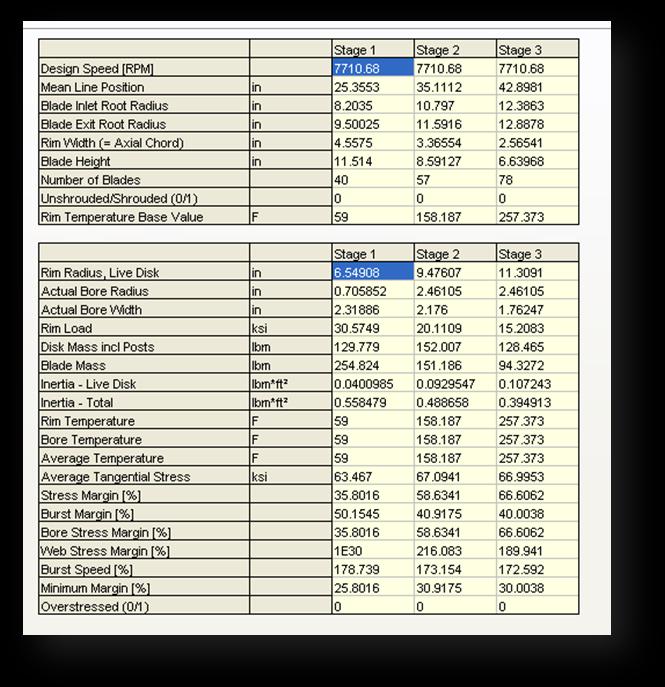
25 Table 16. High Pressure Turbine: Disks (The negative stress margins in stage 2 were subsequently corrected) 25


26 Inter-Turbine Duct Table 17. Inter-Turbine Duct 3.9 Low-Pressure Turbine Table 18. Low Pressure Turbine: General Output


27 Table 19. Low Pressure Turbine: Disks 27


28 Exhaust System & Augmenter The cone ends in the exhaust duct Table 20. Core Exhaust Table 21. Augmenter Table 22. Convergent-Divergent Nozzle
29 29 4. Hints & Suggestions You should first model the baseline engine with the same software that you will use for the new engine design. Your results may not match the baseline engine model exactly but will provide a valid comparison of weights and performance for the new concept engine. The efficiencies of the turbomachinery components may be assumed to be the same as those of the baseline engine, and input directly or the calculate efficiency mode GasTurb11 may be invoked. Instruction in the use of GasTurb11 may be arranged. As stated in the Abstract, the use of design codes from industrial contacts, that are not accessible to all competitors, is not allowed. Even though the date for submission of Letters of Intent is stated as November 1, 2011 on pages 33 and 35, it is recommended that teams who know that they will enter the competition inform either AIAA or Dr. Ian Halliwell (ianhalliwell@earthlink.net) as soon as possible, so that assistance may be given or access to design codes may be arranged. Questions will be taken by volunteers from the AIAA Air Breathing Propulsion Technical Group or the IGTI Aircraft Engines Technical Committee, whose contact information will be provided to teams who submit a letter of intent. The responses will be made available to all participants in the competition via an AIAA website. 5. Competition Expectations The existing rules and guidelines for the AIAA Foundation Student Design Competition should be observed and these are supplied in Appendix 2. In addition, the following specific suggestions are offered for the Engine Design Competition. It is not expected that student teams produce design solutions of industrial quality, however it is hoped that attention will be paid to the practical difficulties encountered in a real-world design situation and that these will be recognized and acknowledged. If such difficulties can be resolved quantitatively, appropriate credit will be given. If suitable design tools and/or knowledge are not available, then a qualitative description of an approach to address the issues is quite acceptable. In a preliminary engine design the following features must be provided:
30 30 Definition and justification of critical mission point(s) that drive the candidate propulsion system design(s). Documentation of the trade studies conducted to determine the preferred engine cycle parameters such as fan pressure ratio, bypass ratio, overall pressure ratio, turbine inlet temperature, etc. An engine configuration with a plot of the flowpath that shows how the major components fit together, with emphasis on operability at different mission points. A clear demonstration of design feasibility, with attention having been paid to technology limits. Stage counts. Estimates of component performance and overall engine performance to show that the assumptions made in the cycle have been achieved. While only the preliminary design of major components in the engine flowpath is expected to be addressed quantitatively in the proposals, it is intended that the role of secondary systems such as fuel & lubrication be given serious consideration in terms of modifications and how they would be integrated in to the new engine design. Credit will be given for clear descriptions of how any appropriate upgrades would be incorporated and how they would affect the engine cycle. Each proposal should also contain a brief discussion of any computer codes or Microsoft Excel spreadsheets used to perform engine design & analysis, with emphasis on any additional special features generated by the team.
31 31 References 1. Aerospace Source Book. Aviation Week & Space Technology. January 15, GasTurb 11: A Design & Off-Design Performance Program for Gas Turbines < Joachim Kurzke, A Simple Correlation of Turbine Efficiency S. F. Smith Journal of the Royal Aeronautical Society. Volume Aeronautical Vest Pocket Handbook. Pratt & Whitney Aircraft. Circa 1980
32 32 Suggested Reading 1. Gas Turbine Theory H.I.H Saravanamuttoo, G.F.C Rogers &.H. Cohen, Prentice Hall. 5 th Edition Aircraft Engine Design J.D.Mattingly, W.H. Heiser, & D.H. Daley AIAA Education Series Elements of Propulsion Gas Turbines and Rockets J.D. Mattingly. AIAA Education Series Jet Propulsion N. Cumpsty. Cambridge University Press Gas Turbine Performance P. Walsh & P. Fletcher. Blackwell/ASME Press. 2 nd Edition, Fundamentals of Jet Propulsion with Applications Ronald D. Flack Cambridge University Press The Jet Engine Rolls-Royce plc
33 33 Appendix 1. Letter of Intent 2011/20012 Joint AIAA IGTI Undergraduate Team Engine Design Competition Request for Proposal: An Engine with High Power Extraction Potential for a Half-Scale Model of a Joint Strike Fighter Title of Design Proposal: Name of School: Designer s Name AIAA or ASME Graduation Date Degree ID or Member # Team Leader Team Leader In order to be eligible for the 2011/2012 Joint AIAA-IGTI Undergraduate Team Engine Design Competition, you must complete this form and return it to the AIAA Student Programs Coordinator before November 1, 2011, at AIAA Headquarters, along with a one-page Letter of Intent, as noted in Appendix 2, Section III, Schedule and Activity Sequences. For any nonmember listed above, a student member application and member dues payment to AIAA should also be included with this form or submitted to ASME, with a note attached. Signature of Faculty Advisor Signature of Project Advisor Date Faculty Advisor Printed Project Advisor Printed Date
34 34 Appendix 2. Rules and Guidelines I. General Rules 1. All undergraduate AIAA or ASME branch or at-large Student Members are eligible and encouraged to participate. 2. Teams will be groups of not more than four AIAA or ASME/IGTI branch or at-large Student Members per entry. 3. An electronic copy of the report in MS Word or Adobe PDF format must be submitted on a CD or DVD to AIAA Student Programs. Total size of the file(s) cannot exceed 60 MB. A Signature page must be included in the report and indicate all participants, including faculty and project advisors, along with their AIAA or ASME member numbers and signatures. Designs that are submitted must be the work of the students, but guidance may come from the Faculty/Project Advisor and should be accurately acknowledged. Graduate student participation in any form is prohibited. 4. Design projects that are used as part of an organized classroom requirement are eligible and encouraged for competition. 5. More than one design may be submitted from students at any one school. 6. If a design group withdraws their project from the competition, the team chairman must notify AIAA Headquarters immediately! 7. Judging will be in two parts. First, the written proposals will be assessed by the judging panel comprised of members of AIAA and IGTI organizing committees from the industrial and government communities. Second, the best three teams will be invited to present their work to a second judging panel at a special technical session at the 48 th AIAA/ASME/SAE/ASEE Joint Propulsion Conference in Atlanta in July Airfare and lodging expenses will be partially covered for the invited teams and their advisors. The results of the presentations will be combined with the earlier scores to determine first, second and third places. 8. The prizes shall be: First place-$2,500; Second place-$1,500; Third place-$1,000 (US dollars). Certificates will be presented to the winning design teams for display at their university and a certificate will also be presented to each team member and the faculty/project advisor.
35 35 II. Copyright All submissions to the competition shall be the original work of the team members. Any submission that does not contain a copyright notice shall become the property of AIAA. A team desiring to maintain copyright ownership may so indicate on the signature page but nevertheless, by submitting a proposal, grants an irrevocable license to AIAA to copy, display, publish, and distribute the work and to use it for all of AIAA s current and future print and electronic uses (e.g. Copyright 20 by. Published by the American Institute of Aeronautics and Astronautics, Inc., with permission.). Any submission purporting to limit or deny AIAA licensure (or copyright) will not be eligible for prizes. III. Schedule & Activity Sequences Significant activities, dates, and addresses for submission of proposal and related materials are as follows: A. Letter of Intent November 1, 2011 B. Receipt of Proposal April 1, 2012 C. Proposal evaluations completed - April 30, 2012 D. Proposal presentations & Announcement of Winners at JPC in Atlanta, GA July 2012 Teams intending to submit a proposal must submit a one page Letter of Intent along with the signed attached Intent Form (Item A) on or before the date specified above, to the following address: AIAA Student Programs 1801 Alexander Bell Drive Suite 500 Reston, VA The CD containing the finished proposal must be received at the same address on or before the date specified above for the Receipt of Proposal (Item B). IV. Proposal Requirements The technical proposal is the most important factor in the award of a contract. It should be specific and complete. While it is realized that all of the technical factors cannot be included in advance, the following should be included and keyed accordingly:
36 36 1. Demonstrate a thorough understanding of the Request for Proposal (RFP) requirements. 2. Describe the proposed technical approaches to comply with each of the requirements specified in the RFP, including phasing of tasks. Legibility, clarity, and completeness of the technical approach are primary factors in evaluation of the proposals. 3. Particular emphasis should be directed at identification of critical, technical problem areas. Descriptions, sketches, drawings, systems analysis, method of attack, and discussions of new techniques should be presented in sufficient detail to permit engineering evaluation of the proposal. Exceptions to proposed technical requirements should be identified and explained. 4. Include tradeoff studies performed to arrive at the final design. 5. Provide a description of automated design tools used to develop the design. V. Basis for Judging A. Proposal 1. Technical Content (35 points) This concerns the correctness of theory, validity of reasoning used, apparent understanding and grasp of the subject, etc. Are all major factors considered and a reasonably accurate evaluation of these factors presented? 2. Organization and Presentation (20 points) The description of the design as an instrument of communication is a strong factor on judging. Organization of written design, clarity, and inclusion of pertinent information are major factors. 3. Originality (20 points) The design proposal should avoid standard textbook information, and should show independence of thinking or a fresh approach to the project. Does the method and treatment of the problem show imagination? Does the approach show an adaptation or creation of automated design tools? 4. Practical Application and Feasibility (25 points) The proposal should present conclusions or recommendations that are feasible and practical, and not merely lead the evaluators into further difficult or insolvable problems. B. Presentation Each team will have 40 minutes to present a summary of its proposal to the judging panel. In addition to the categories above, the presentations will be assessed for clarity, effectiveness and the ability to sell the teams ideas.
AIAA Foundation Undergraduate Team Aircraft Design Competition. RFP: Cruise Missile Carrier
 AIAA Foundation Undergraduate Team Aircraft Design Competition RFP: Cruise Missile Carrier 1999/2000 AIAA FOUNDATION Undergraduate Team Aircraft Design Competition I. RULES 1. All groups of three to ten
An Ultra-High Bypass Ratio Turbofan Engine for the Future
 Undergraduate Team Engine Student Design Competition 2014/15 An Ultra-High Bypass Ratio Turbofan Engine for the Future - Request for Proposal - September 13, 2014 2 Abstract Major engine manufacturers
2000/2001 AIAA FOUNDATION Undergraduate Team Aircraft Design Competition
 2000/2001 AIAA FOUNDATION Undergraduate Team Aircraft Design Competition I. RULES 1. All groups of 3 to 10 undergraduate AIAA branch or at-large Student Members are eligible and encouraged to participate.
2012/2013 AIAA Foundation Graduate Team Aircraft Design Competition
 2012/2013 AIAA Foundation Graduate Team Aircraft Design Competition High Altitude Long Endurance (HALE)Unmanned Aerial System (UAS) for Missile Defense with Directed Energy (DE) Laser Weapon I. Rules-General
The winner team will have the opportunity to perform a wind tunnel test campaign in the transonic/supersonic Wind tunnel at the VKI.
 Aircraft Design Competition Request for proposal (RFP) - High speed UAV Objectives: This RFP asks for an original UAV design capable of reaching, in less than 15 minutes, a given target located at 150
Welcome to Aerospace Engineering
 Welcome to Aerospace Engineering DESIGN-CENTERED INTRODUCTION TO AEROSPACE ENGINEERING Notes 5 Topics 1. Course Organization 2. Today's Dreams in Various Speed Ranges 3. Designing a Flight Vehicle: Route
Chapter 4 Lecture 16. Engine characteristics 4. Topics. Chapter IV
 Chapter 4 Lecture 16 Engine characteristics 4 Topics 4.3.3 Characteristics of a typical turboprop engine 4.3.4 Characteristics of a typical turbofan engine 4.3.5 Characteristics of a typical turbojet engines
Chapter 4 Estimation of wing loading and thrust loading - 10 Lecture 18 Topics
 Chapter 4 Estimation of wing loading and thrust loading - 10 Lecture 18 Topics 4.15.3 Characteristics of a typical turboprop engine 4.15.4 Characteristics of a typical turbofan engine 4.15.5 Characteristics
Engine Performance Analysis
 Engine Performance Analysis Introduction The basics of engine performance analysis The parameters and tools used in engine performance analysis Introduction Parametric cycle analysis: Independently selected
Request for Proposal Electric Vertical Takeoff and Landing (E-VTOL) Aircraft
 Aircraft") Request for Proposal Electric Vertical Takeoff and Landing (E-VTOL) Aircraft Opportunity Description The recent and continuing development in technological state-of-the-art for electric motors, power electronics,
Request for Proposal Electric Vertical Takeoff and Landing (E-VTOL) Aircraft Opportunity Description The recent and continuing development in technological state-of-the-art for electric motors, power electronics,
FLUIDIC THRUST VECTORING NOZZLES
 FLUIDIC THRUST VECTORING NOZZLES J.J. Isaac and C. Rajashekar Propulsion Division National Aerospace Laboratories (Council of Scientific & Industrial Research) Bangalore 560017, India April 2014 SUMMARY
Jet Propulsion. Lecture-13. Ujjwal K Saha, Ph. D. Department of Mechanical Engineering Indian Institute of Technology Guwahati
 Lecture-13 Prepared under QIP-CD Cell Project Jet Propulsion Ujjwal K Saha, Ph. D. Department of Mechanical Engineering Indian Institute of Technology Guwahati 1 GE J79 Turbojet 2 Features Highly used
Design Rules and Issues with Respect to Rocket Based Combined Cycles
 Respect to Rocket Based Combined Cycles Tetsuo HIRAIWA hiraiwa.tetsuo@jaxa.jp ABSTRACT JAXA Kakuda space center has been studying rocket based combined cycle engine for the future space transportation
2019 SpaceX Hyperloop Pod Competition
 2019 SpaceX Hyperloop Pod Competition Rules and Requirements August 23, 2018 CONTENTS 1 Introduction... 2 2 General Information... 3 3 Schedule... 4 4 Intent to Compete... 4 5 Preliminary Design Briefing...
Design and Test of Transonic Compressor Rotor with Tandem Cascade
 Proceedings of the International Gas Turbine Congress 2003 Tokyo November 2-7, 2003 IGTC2003Tokyo TS-108 Design and Test of Transonic Compressor Rotor with Tandem Cascade Yusuke SAKAI, Akinori MATSUOKA,
Jet Aircraft Propulsion Prof. Bhaskar Roy Prof. A.M. Pradeep Department of Aerospace Engineering Indian Institute of Technology, Bombay
 Jet Aircraft Propulsion Prof. Bhaskar Roy Prof. A.M. Pradeep Department of Aerospace Engineering Indian Institute of Technology, Bombay Lecture No. # 04 Turbojet, Reheat Turbojet and Multi-Spool Engines
In this lecture... Prof. Bhaskar Roy, Prof. A M Pradeep, Department of Aerospace, IIT Bombay
 1 In this lecture... Intakes for powerplant Transport aircraft Military aircraft 2 Intakes Air intakes form the first component of all air breathing propulsion systems. The word Intake is normally used
UNCLASSIFIED FY 2017 OCO. FY 2017 Base
 Exhibit R-2, RDT&E Budget Item Justification: PB 2017 Air Force Date: February 2016 3600: Research, Development, Test & Evaluation, Air Force / BA 2: Applied Research COST ($ in Millions) Prior Years FY
TCDS NUMBER E00078NE U.S. DEPARTMENT OF TRANSPORTATION REVISION: 3 DATE: April 12, 2011
 TCDS NUMBER E00078NE U.S. DEPARTMENT OF TRANSPORTATION REVISION: 3 DATE: April 12, 2011 FEDERAL AVIATION ADMINISTRATION GENERAL ELECTRIC COMPANY MODELS: TYPE CERTIFICATE DATA SHEET E00078NE GEnx-1B54 GEnx-1B58
In this lecture... Fixed and variable geometry nozzles Functions of nozzles Thrust vector control Thrust reversal Noise control
 1 In this lecture... Nozzle: Fixed and variable geometry nozzles Functions of nozzles Thrust vector control Thrust reversal Noise control 2 Exhaust nozzles Nozzles form the exhaust system of gas turbine
State Legislation, Regulation or Document Reference. Civil Aviation Rule (CAR) ; Civil Aviation Rules (CAR) Part 21. Appendix C.
 ; Civil Aviation Rules (CAR) Part 21. Appendix C.") Annex or Recommended Practice Definition INTERNATIONAL STANDARDS AND RECOMMENDED PRACTICES PART I. DEFINITIONS AND SYMBOLS Civil Aviation Rule (CAR) 91.807; Civil Aviation Rules (CAR) Part 21 The s of
Annex or Recommended Practice Definition INTERNATIONAL STANDARDS AND RECOMMENDED PRACTICES PART I. DEFINITIONS AND SYMBOLS Civil Aviation Rule (CAR) 91.807; Civil Aviation Rules (CAR) Part 21 The s of
SR-71 PROPULSION SYSTEM P&W J58 ENGINE (JT11D-20) ONE OF THE BEST JET ENGINES EVER BUILT
 ONE OF THE BEST JET ENGINES EVER BUILT") SR-71 PROPULSION SYSTEM P&W J58 ENGINE (JT11D-20) PETER LAW ONE OF THE BEST JET ENGINES EVER BUILT Rolls-Royce Milestone Engines Merlin Conway W2B Welland Derwent Trent SR-71 GENERAL CHARACTERISTICS
SR-71 PROPULSION SYSTEM P&W J58 ENGINE (JT11D-20) PETER LAW ONE OF THE BEST JET ENGINES EVER BUILT Rolls-Royce Milestone Engines Merlin Conway W2B Welland Derwent Trent SR-71 GENERAL CHARACTERISTICS
(VTOL) Propulsion Systems Design
 Propulsion Systems Design") 72-GT-73 $3.00 PER COPY $1.00 TO ASME MEMBERS The Society shall not be responsible for statements or opinions advanced in papers or in discussion at meetings of the Society or of its Divisions or Sections,
72-GT-73 $3.00 PER COPY $1.00 TO ASME MEMBERS The Society shall not be responsible for statements or opinions advanced in papers or in discussion at meetings of the Society or of its Divisions or Sections,
BAYLOR UNIVERSITY DEPARTMENT OF ENGINEERING. EGR 4347 Analysis and Design of Propulsion Systems Fall 2002 ASSIGNMENT GUIDELINES
 BAYLOR UNIVERSITY DEPARTMENT OF ENGINEERING EGR 4347 Analysis and Design of Propulsion Systems Fall 2002 Design Project I Dr Van Treuren 100 points ASSIGNMENT GUIDELINES For this assignment, you may work
Preface. Acknowledgments. List of Tables. Nomenclature: organizations. Nomenclature: acronyms. Nomenclature: main symbols. Nomenclature: Greek symbols
 Contents Preface Acknowledgments List of Tables Nomenclature: organizations Nomenclature: acronyms Nomenclature: main symbols Nomenclature: Greek symbols Nomenclature: subscripts/superscripts Supplements
European Aviation Safety Agency
 European Aviation Safety Agency EASA TYPE-CERTIFICATE DATA SHEET Number : IM.E.016 Issue : 07 Date : 21 May 2014 Type : Williams International Co. FJ44 Series Engines s FJ44-1A FJ44-1AP FJ44-2A FJ44-2C
Undergraduate Team Engine Candidate Engines for a Next Generation Supersonic Transport ETU V TULPAR
 2017-2018 Undergraduate Team Engine Candidate Engines for a Next Generation Supersonic Transport ETU V TULPAR TEAM MEMBERS Veli Can ÜSTÜNDAĞ - 921399 Çağdaş Cem ERGİN - 920976 Baran İPER - 921398 Onur
ME3264: LAB 9 Gas Turbine Power System
 OBJECTIVE ME3264: LAB 9 Gas Turbine Power System Professor Chih-Jen Sung Spring 2013 A fully integrated jet propulsion system will be used for the study of thermodynamic and operating principles of gas
Metrovick F2/4 Beryl. Turbo-Union RB199
 Turbo-Union RB199 Metrovick F2/4 Beryl Development of the F2, the first British axial flow turbo-jet, began in f 940. After initial flight trials in the tail of an Avro Lancaster, two F2s were installed
NEWAC Overall Specification, Assessment and Concept Optimization
 NEWAC Overall Specification, Assessment and Concept Optimization Andrew Rolt, Rolls-Royce plc. with contributions from: Konstantinos Kyprianidis, Cranfield University; Stefan Donnerhack and Wolfgang Sturm,
Aerospace Propulsion Systems
 Brochure More information from http://www.researchandmarkets.com/reports/1288672/ Aerospace Propulsion Systems Description: Aerospace Propulsion Systems is a unique book focusing on each type of propulsion
JET AIRCRAFT PROPULSION
 1 JET AIRCRAFT PROPULSION a NPTEL-II Video Course for Aerospace Engineering Students Bhaskar Roy and A M Pradeep Aerospace Engineering Department I.I.T., Bombay 2 Brief outline of the syllabus Introduction
TURBOPROP ENGINE App. K AIAA AIRCRAFT ENGINE DESIGN
 CORSO DI LAUREA SPECIALISTICA IN Ingegneria Aerospaziale PROPULSIONE AEROSPAZIALE I TURBOPROP ENGINE App. K AIAA AIRCRAFT ENGINE DESIGN www.amazon.com LA DISPENSA E E DISPONIBILE SU http://www.ingindustriale.unisalento.it/didattica/
Gujarat, India,
 Experimental Analysis of Convergent, Convergent Divergent nozzles at various mass flow rates for pressure ratio and pressure along the length of nozzle Rakesh K. Bumataria 1, Darpan V. Patel 2, Sharvil
Economic Impact of Derated Climb on Large Commercial Engines
 Economic Impact of Derated Climb on Large Commercial Engines Article 8 Rick Donaldson, Dan Fischer, John Gough, Mike Rysz GE This article is presented as part of the 2007 Boeing Performance and Flight
Study on Flow Fields in Variable Area Nozzles for Radial Turbines
 Vol. 4 No. 2 August 27 Study on Fields in Variable Area Nozzles for Radial Turbines TAMAKI Hideaki : Doctor of Engineering, P. E. Jp, Manager, Turbo Machinery Department, Product Development Center, Corporate
AIRCRAFT AND TECHNOLOGY CONCEPTS FOR AN N+3 SUBSONIC TRANSPORT. Elena de la Rosa Blanco May 27, 2010
 AIRCRAFT AND TECHNOLOGY CONCEPTS FOR AN N+3 SUBSONIC TRANSPORT MIT, Aurora Flights Science, and Pratt & Whitney Elena de la Rosa Blanco May 27, 2010 1 The information in this document should not be disclosed
AE 451 Aeronautical Engineering Design Final Examination. Instructor: Prof. Dr. Serkan ÖZGEN Date:
 Instructor: Prof. Dr. Serkan ÖZGEN Date: 11.01.2012 1. a) (8 pts) In what aspects an instantaneous turn performance is different from sustained turn? b) (8 pts) A low wing loading will always increase
Jay Gundlach AIAA EDUCATION SERIES. Manassas, Virginia. Joseph A. Schetz, Editor-in-Chief. Blacksburg, Virginia. Aurora Flight Sciences
 Jay Gundlach Aurora Flight Sciences Manassas, Virginia AIAA EDUCATION SERIES Joseph A. Schetz, Editor-in-Chief Virginia Polytechnic Institute and State University Blacksburg, Virginia Published by the
Study of Inlet Guide Vanes for Centrifugal Compressor in Miniature Gas-Turbines
 Study of Inlet Guide Vanes for Centrifugal Compressor in Miniature Gas-Turbines Ronald Reagon R 1 Roshan Suhail 2, Shashank N 3, Ganesh Nag 4 Vishnu Tej 5 1 Asst. Professor, Department of Mechanical Engineering,
Prof. João Melo de Sousa Instituto Superior Técnico Aerospace & Applied Mechanics. Part B Acoustic Emissions 4 Airplane Noise Sources
 Prof. João Melo de Sousa Instituto Superior Técnico Aerospace & Applied Mechanics Part B Acoustic Emissions 4 Airplane Noise Sources The primary source of noise from an airplane is its propulsion system.
Auto Service Technician
 Auto Service Technician Organization Washburn Institute of Technology Program Number 47.0604 Instructional Level Certificate Target Population Grades 11 & 12 Post-secondary Description The Auto Service
TYPE-CERTIFICATE DATA SHEET
 TYPE-CERTIFICATE DATA SHEET No. EASA E.047 for RB211 Trent 800 series engines Type Certificate Holder 62 Buckingham Gate Westminster London SW1E 6AT United Kingdom For Models: RB211 Trent 895-17 RB211
Noise and Noise Reduction in Supersonic Jets
 Noise and Noise Reduction in Supersonic Jets Philip J. Morris and Dennis K. McLaughlin The Pennsylvania State University Department of Aerospace Engineering Presented at FLINOVIA 2017 State College, PA
APPLICATION OF STAR-CCM+ TO TURBOCHARGER MODELING AT BORGWARNER TURBO SYSTEMS
 APPLICATION OF STAR-CCM+ TO TURBOCHARGER MODELING AT BORGWARNER TURBO SYSTEMS BorgWarner: David Grabowska 9th November 2010 CD-adapco: Dean Palfreyman Bob Reynolds Introduction This presentation will focus
TYPE-CERTIFICATE DATA SHEET
 TYPE-CERTIFICATE DATA SHEET EASA.E.060 for RB211 Trent 500 Series Engines Type Certificate Holder 62 Buckingham Gate Westminster London SW1E 6AT United Kingdom For Models: RB211 Trent 553-61 RB211 Trent
ia 451s, 10-y (12) Patent Application Publication (10) Pub. No.: US 2003/ A1 (19) United States Johnson et al. (43) Pub. Date: Feb.
 Patent Application Publication (10) Pub. No.: US 2003/ A1 (19) United States Johnson et al. (43) Pub. Date: Feb.") (19) United States US 2003OO29160A1 (12) Patent Application Publication (10) Pub. No.: US 2003/0029160 A1 Johnson et al. (43) Pub. Date: Feb. 13, 2003 (54) COMBINED CYCLE PULSE DETONATION TURBINE ENGINE
(19) United States US 2003OO29160A1 (12) Patent Application Publication (10) Pub. No.: US 2003/0029160 A1 Johnson et al. (43) Pub. Date: Feb. 13, 2003 (54) COMBINED CYCLE PULSE DETONATION TURBINE ENGINE
Introduction to the ICAO Engine Emissions Databank
 Introduction to the ICAO Engine Emissions Databank Background Standards limiting the emissions of smoke, unburnt hydrocarbons (HC), carbon monoxide (CO) and oxides of nitrogen (NOx) from turbojet and turbofan
Modern Approach to Liquid Rocket Engine Development for Microsatellite Launchers
 Modern Approach to Liquid Rocket Engine Development for Microsatellite Launchers SoftInWay: Turbomachinery Mastered 2018 SoftInWay, Inc. All Rights Reserved. Introduction SoftInWay: Turbomachinery Mastered
Proposed Special Condition for limited Icing Clearances Applicable to Large Rotorcraft, CS 29 or equivalent. ISSUE 1
 Proposed Special Condition for limited Icing Clearances Applicable to Large Rotorcraft, CS 29 or equivalent. ISSUE 1 Introductory note: The hereby presented Special Condition has been classified as important
Corso di Motori Aeronautici
 Corso di Motori Aeronautici Mauro Valorani Laurea Magistrale in Ingegneria Aeronautica (MAER) Sapienza, Università di Roma Anno Accademico 2011-12 Sett. 13: Conclusioni 1 FP7 Aero Engine Scenario ERS Strategy
COPYRIGHTED MATERIAL. Introduction. 1.1 Gas Turbine Concepts
 1 Introduction The modern gas turbine engine used for aircraft propulsion is a complex machine comprising many systems and subsystems that are required to operate together as a complex integrated entity.
November 8, 2018 GAS TURBINE ENGINE SECONDARY FLOW SYSTEMS
 November 8, 2018 GAS TURBINE ENGINE SECONDARY FLOW SYSTEMS Agenda 1 What is Secondary Flow? Purpose for the Secondary Flow Systems Chargeable Vs Nonchargeable Flows Seals Selection and Leakage Effects
Experimental Testing of a Rotating Detonation Engine Coupled to Nozzles at Conditions Approaching Flight
 25 th ICDERS August 2 7, 205 Leeds, UK Experimental Testing of a Rotating Detonation Engine Coupled to Nozzles at Conditions Approaching Flight Matthew L. Fotia*, Fred Schauer Air Force Research Laboratory
Development and Implementation of Interactive/Visual Software for Simple Aircraft Gas Turbine Design
 Development and Implementation of Interactive/Visual Software for Simple Aircraft Gas Turbine Design Afshin J. Ghajar, Ronald D. Delahoussaye, Vandan V. Nayak School of Mechanical and Aerospace Engineering,
CONCEPTUAL DESIGN OF A LOW-BYPASS TURBOFAN ENGINE FOR NEXT GENERATION JET TRAINER
 9 th ANKARA INTERNATIONAL AEROSPACE CONFERENCE AIAC-2017-130 20-22 September 2017 - METU, Ankara TURKEY CONCEPTUAL DESIGN OF A LOW-BYPASS TURBOFAN ENGINE FOR NEXT GENERATION JET TRAINER Olcay Sari and
AE 452 Aeronautical Engineering Design II Installed Engine Performance. Prof. Dr. Serkan Özgen Dept. Aerospace Engineering March 2016
 AE 452 Aeronautical Engineering Design II Installed Engine Performance Prof. Dr. Serkan Özgen Dept. Aerospace Engineering March 2016 Propulsion 2 Propulsion F = ma = m V = ρv o S V V o ; thrust, P t =
European Aviation Safety Agency
 European Aviation Safety Agency EASA TYPE-CERTIFICATE DATA SHEET Number : E.036 Issue : 04 Date : 10 September 2013 Type : Rolls-Royce plc Trent 1000 series engines Models Trent 1000-A Trent 1000-A2 Trent
STUDY OF INFLUENCE OF ENGINE CONTROL LAWS ON TAKEOFF PERFORMANCES AND NOISE AT CONCEPTUAL DESIGN OF SSBJ PROPULSION SYSTEM
 7 TH INTERNATIONAL CONGRESS OF THE AERONAUTICAL SCIENCES STUDY OF INFLUENCE OF ENGINE CONTROL LAWS ON TAKEOFF PERFORMANCES AND NOISE AT CONCEPTUAL DESIGN OF SSBJ PROPULSION SYSTEM Pavel A. Ryabov Central
AERONAUTICAL ENGINEERING
 AERONAUTICAL ENGINEERING SHIBIN MOHAMED Asst. Professor Dept. of Mechanical Engineering Al Ameen Engineering College Al- Ameen Engg. College 1 Aerodynamics-Basics These fundamental basics first must be
Environmentally Focused Aircraft: Regional Aircraft Study
 Environmentally Focused Aircraft: Regional Aircraft Study Sid Banerjee Advanced Design Product Development Engineering, Aerospace Bombardier International Workshop on Aviation and Climate Change May 18-20,
CONFERENCE ON AVIATION AND ALTERNATIVE FUELS
 CAAF/09-IP/11 19/10/09 English only CONFERENCE ON AVIATION AND ALTERNATIVE FUELS Rio de Janeiro, Brazil, 16 to 18 November 2009 Agenda Item 1: Environmental sustainability and interdependencies IMPACT
Effects of Dilution Flow Balance and Double-wall Liner on NOx Emission in Aircraft Gas Turbine Engine Combustors
 Effects of Dilution Flow Balance and Double-wall Liner on NOx Emission in Aircraft Gas Turbine Engine Combustors 9 HIDEKI MORIAI *1 Environmental regulations on aircraft, including NOx emissions, have
application of simplified algorithm to dramatically reduce specific fuel consumption
 application of simplified algorithm to dramatically reduce specific fuel consumption This white paper considers the challenges of turbine active clearance control and proposes a unique approach in reducing
European Aviation Safety Agency
 European Aviation Safety Agency EASA TYPE-CERTIFICATE DATA SHEET Number : EASA.(IM).E.049 Issue : 01 Date : 19 November 2014 Type : Pratt & Whitney Canada PW150 series Models PW150A List of effective Pages:
HERCULES-2 Project. Deliverable: D8.8
 HERCULES-2 Project Fuel Flexible, Near Zero Emissions, Adaptive Performance Marine Engine Deliverable: D8.8 Study an alternative urea decomposition and mixer / SCR configuration and / or study in extended
Higher National Unit Specification. General information for centres. Electrical Motors and Motor Starting. Unit code: DV9M 34
 Higher National Unit Specification General information for centres Unit title: Electrical Motors and Motor Starting Unit code: DV9M 34 Unit purpose: This Unit has been developed to provide candidates with
THE AIRBUS / ENGINE & NACELLE MANUFACTURERS RELATIONSHIP : TOWARDS A MORE INTEGRATED, ENVIRONMENTALLY FRIENDLY ENGINEERING DESIGN
 24 TH INTERNATIONAL CONGRESS OF THE AERONAUTICAL SCIENCES THE AIRBUS / ENGINE & NACELLE MANUFACTURERS RELATIONSHIP : TOWARDS A MORE INTEGRATED, ENVIRONMENTALLY FRIENDLY ENGINEERING DESIGN Sébastien Remy
Presented at the 2012 Aerospace Space Power Workshop Manhattan Beach, CA April 16-20, 2012
 Complex Modeling of LiIon Cells in Series and Batteries in Parallel within Satellite EPS Time Dependent Simulations Presented at the 2012 Aerospace Space Power Workshop Manhattan Beach, CA April 16-20,
Lessons in Systems Engineering. The SSME Weight Growth History. Richard Ryan Technical Specialist, MSFC Chief Engineers Office
 National Aeronautics and Space Administration Lessons in Systems Engineering The SSME Weight Growth History Richard Ryan Technical Specialist, MSFC Chief Engineers Office Liquid Pump-fed Main Engines Pump-fed
Aircraft Propulsion Technology
 Unit 90: Aircraft Propulsion Technology Unit code: L/601/7249 QCF level: 4 Credit value: 15 Aim This unit aims to develop learners understanding of the principles and laws of aircraft propulsion and their
(Refer Slide Time: 1:13)
") Fluid Dynamics And Turbo Machines. Professor Dr Dhiman Chatterjee. Department Of Mechanical Engineering. Indian Institute Of Technology Madras. Part A. Module-2. Lecture-2. Turbomachines: Definition and
Fluid Dynamics And Turbo Machines. Professor Dr Dhiman Chatterjee. Department Of Mechanical Engineering. Indian Institute Of Technology Madras. Part A. Module-2. Lecture-2. Turbomachines: Definition and
DESIGN AND ANALYSIS OF UNDERTRAY DIFFUSER FOR A FORMULA STYLE RACECAR
 DESIGN AND ANALYSIS OF UNDERTRAY DIFFUSER FOR A FORMULA STYLE RACECAR Ali Asgar S. Khokhar 1, Suhas S. Shirolkar 2 1 Graduate in Mechanical Engineering, KJ Somaiya College of Engineering, Mumbai, India.
DEPARTMENT OF TRANSPORTATION FEDERAL AVIATION ADMINISTRATION TYPE CERTIFICATE DATA SHEET NO. 1E8
 DEPARTMENT OF TRANSPORTATION FEDERAL AVIATION ADMINISTRATION 1E8 Revision 18 PRATT & WHITNEY AIRCRAFT TURBO WASP JT3D-1 JT3D-3 JT3D-1A JT3D-3B JT3D-1-MC6 JT3D-3C JT3D-1A-MC6 JT3D-7 JT3D-1-MC7 JT3D-7A JT3D-1A-MC7
Plasma Assisted Combustion in Complex Flow Environments
 High Fidelity Modeling and Simulation of Plasma Assisted Combustion in Complex Flow Environments Vigor Yang Daniel Guggenheim School of Aerospace Engineering Georgia Institute of Technology Atlanta, Georgia
TYPE CERTIFICATE DATA SHEET
 TYPE CERTIFICATE DATA SHEET No. IM.E.096 for PW800 Series Engines Type Certificate Holder 1000 Marie Victorin Longueuil, Quebec J4G1A1 Canada For : TE.CERT.00052 001 European Aviation Safety Agency, 2016.
SILENT SUPERSONIC TECHNOLOGY DEMONSTRATION PROGRAM
 25 TH INTERNATIONAL CONGRESS OF THE AERONAUTICAL SCIENCES SILENT SUPERSONIC TECHNOLOGY DEMONSTRATION PROGRAM Akira Murakami* *Japan Aerospace Exploration Agency Keywords: Supersonic, Flight experiment,
Overview of Helicopter HUMS Research in DSTO Air Vehicles Division
 AIAC-12 Twelfth Australian International Aerospace Congress Overview of Helicopter HUMS Research in DSTO Air Vehicles Division Dr Ken Anderson 1 Chief Air Vehicles Division DSTO Australia Abstract: This
TYPE-CERTIFICATE DATA SHEET
 TYPE-CERTIFICATE DATA SHEET No. IM.E.016 issue 10 for FJ44/FJ33 Series Engines Certificate Holder Williams International Co. Walled Lake Michigan 48390-0200 USA For Models: FJ44-1A FJ44-1AP FJ44-2A FJ44-2C
TERMS AND CONDITIONS
 XXV. NET METERING A. Applicability and Availability 1. The terms Net Metering Service, Demand Charge-based Time-of- Use Tariff, Net Metering Customer, Customer, Time-of-Use Customer, Time-of-Use Tier,
FLEXIBLE, FAST AND HIGH FIDELITY APPROACH TO GTU PART-LOAD AND OFF-DESIGN PERFORMANCE PREDICTIONS
 TETS 2018, Dayton Convention Center, Dayton, Ohio, Sept. 10-13, 2018 FLEXIBLE, FAST AND HIGH FIDELITY APPROACH TO GTU PART-LOAD AND OFF-DESIGN PERFORMANCE PREDICTIONS Presenter: Co-Authors: Company: Dr.
Reducing Landing Distance
 Reducing Landing Distance I've been wondering about thrust reversers, how many kinds are there and which are the most effective? I am having a debate as to whether airplane engines reverse, or does something
TYPE-CERTIFICATE DATA SHEET
 TYPE-CERTIFICATE DATA SHEET EASA.E.042 for RB211 Trent 700 series engines Type Certificate Holder 62 Buckingham Gate Westminster London SW1E 6AT United Kingdom For Models: RB211 Trent 768-60 RB211 Trent
Fig 2: Grid arrangements for axis-symmetric Rocket nozzle.
 CFD Analysis of Rocket-Ramjet Combustion Chamber 1 Ms. P.Premalatha, Asst. Prof., PSN College of Engineering and Technology, Tirunelveli. 1prema31194@gmail.com 1 +91-90475 26413 2 Ms. T. Esakkiammal, Student,
AUTOMATED SELECTION OF THE MATERIAL A FAN BLADE PS-90A
 AUTOMATED SELECTION OF THE MATERIAL A FAN BLADE PS-90A D. A. Akhmedzyanov, A. E. Kishalov, K. V. Markina USATU Ufa State Aviation Technical University, Russia Keywords: GTE, fan blade, composite material,
Team Introduction Competition Background Current Situation Project Goals Stakeholders Use Scenario Customer Needs Engineering Requirements
 Team Introduction Competition Background Current Situation Project Goals Stakeholders Use Scenario Customer Needs Engineering Requirements Constraints Project Plan Risk Analysis Questions Christopher Jones
Appenidix E: Freewing MAE UAV analysis
 Appenidix E: Freewing MAE UAV analysis The vehicle summary is presented in the form of plots and descriptive text. Two alternative mission altitudes were analyzed and both meet the desired mission duration.
AIRCRAFT DESIGN SUBSONIC JET TRANSPORT
 AIRCRAFT DESIGN SUBSONIC JET TRANSPORT Analyzed by: Jin Mok Professor: Dr. R.H. Liebeck Date: June 6, 2014 1 Abstract The purpose of this report is to design the results of a given specification and to
Introduction to Gas Turbine Engines
 Introduction to Gas Turbine Engines Introduction Gas Turbine Engine - Configurations Gas Turbine Engine Gas Generator Compressor is driven by the turbine through an interconnecting shaft Turbine is driven
Training Title GAS TURBINE AND COMPRESSOR OPERATION, MAINTENANCE AND TROUBLESHOOTING
 Training Title GAS TURBINE AND COMPRESSOR OPERATION, MAINTENANCE AND TROUBLESHOOTING Training Duration 5 days Training Venue and Dates Gas Turbine and Compressor Operation, Maintenance and Troubleshooting
SAE Mini BAJA: Suspension and Steering
 SAE Mini BAJA: Suspension and Steering By Zane Cross, Kyle Egan, Nick Garry, Trevor Hochhaus Team 11 Progress Report Submitted towards partial fulfillment of the requirements for Mechanical Engineering
Flight Test Evaluation of C-130H Aircraft Performance with NP2000 Propellers
 Flight Test Evaluation of C-130H Aircraft Performance with NP2000 Propellers Lance Bays Lockheed Martin - C-130 Flight Sciences Telephone: (770) 494-8341 E-Mail: lance.bays@lmco.com Introduction Flight
Designing evtol for the Mission NDARC NASA Design and Analysis of Rotorcraft. Wayne Johnson From VTOL to evtol Workshop May 24, 2018
 Designing evtol for the Mission NDARC NASA Design and Analysis of Rotorcraft Wayne Johnson From VTOL to evtol Workshop May 24, 2018 1 Conceptual Design of evtol Aircraft Conceptual design Define aircraft
A REPORT ON THE STATISTICAL CHARACTERISTICS of the Highlands Ability Battery CD
 A REPORT ON THE STATISTICAL CHARACTERISTICS of the Highlands Ability Battery CD Prepared by F. Jay Breyer Jonathan Katz Michael Duran November 21, 2002 TABLE OF CONTENTS Introduction... 1 Data Determination
Chapter 9 GAS POWER CYCLES
 Thermodynamics: An Engineering Approach, 6 th Edition Yunus A. Cengel, Michael A. Boles McGraw-Hill, 2008 Chapter 9 GAS POWER CYCLES Copyright The McGraw-Hill Companies, Inc. Permission required for reproduction
FUEL CONSUMPTION DUE TO SHAFT POWER OFF-TAKES FROM THE ENGINE
 FUEL CONSUMPTION DUE TO SHAFT POWER OFF-TAKES FROM THE ENGINE Dieter Scholz, Ravinkha Sereshine, Ingo Staack, Craig Lawson FluMeS Fluid and Mechatronic Systems Table of Contents Research Question Secondary
TF-CLAWS: Candidate Low-Bypass, Mixed-Flow Turbofan Engine for a Next Generation Trainer
 TF-CLAWS: Candidate Low-Bypass, Mixed-Flow Turbofan Engine for a Next Generation Trainer Faculty Advisors: Saeed Farokhi and Ray Taghvi Team Lead: Kyle P. Thompson Team Members: Daniel Fought Department
Revisiting the Calculations of the Aerodynamic Lift Generated over the Fuselage of the Lockheed Constellation
 Eleventh LACCEI Latin American and Caribbean Conference for Engineering and Technology (LACCEI 2013) International Competition of Student Posters and Paper, August 14-16, 2013 Cancun, Mexico. Revisiting
Baugh Wind Energy Design Competition Saturday, 9 February 2019
 Baugh Wind Energy Design Competition Saturday, 9 February 2019 Oklahoma Christian University is pleased to announce the third annual wind energy design competition for middle school and high school students.
AE Aircraft Performance and Flight Mechanics
 AE 429 - Aircraft Performance and Flight Mechanics Propulsion Characteristics Types of Aircraft Propulsion Mechanics Reciprocating engine/propeller Turbojet Turbofan Turboprop Important Characteristics: