Modern Approach to Liquid Rocket Engine Development for Microsatellite Launchers
|
|
|
- Philip Barnett
- 5 years ago
- Views:
Transcription

1 Modern Approach to Liquid Rocket Engine Development for Microsatellite Launchers SoftInWay: Turbomachinery Mastered 2018 SoftInWay, Inc. All Rights Reserved.
2 Introduction SoftInWay: Turbomachinery Mastered 2

3 Nano/Microsatellite Definition * These satellites have been carried to space as secondary payloads aboard larger launchers for many years. However, the secondary payload method does not offer the specificity required for modern day demands such as increasingly sophisticated small satellites that have unique orbital and launch-time requirements. * 2018 Nano/Microsatellite Market Forecast, 8 th Edition, SpaceWorks, 2018 SoftInWay: Turbomachinery Mastered 3

4 2018 Nano/Microsatellite Launch History & Market Forecast (1-50 kg) * The competition in the launch industry is getting progressively more aggressive and dynamic SpaceWorks 2018 forecast predicts 263 nano/microsatellite launches this year 25+ companies are pursuing the development of new small satellite vehicles * 2018 Nano/Microsatellite Market Forecast, 8 th Edition, SpaceWorks, 2018 SoftInWay: Turbomachinery Mastered 4

5 Launch Vehicle Cost Breakdown by Major Elements* During the first stage of a launch vehicle s development, the majority of the cost comes from the engine, followed by the structures (as seen below). The development duration becomes extremely important in both minimizing launch cost and supplying the launcher when needed. Even the highest performing and cost-efficient vehicle can become useless if not supplied on time in such a competitive and dynamic market The system design approach applied to rocket engine design is a potential way to reduce development time * Salvatore T. Bruno, Launch Vehicle Weight and Cost by Major Elements, United Launch Alliance (ULA), 2015 SoftInWay: Turbomachinery Mastered 5
6 Goal of the Study Reduce liquid rocket engine development time by leveraging an automatic system engineering approach focused on preliminary design of the thrust nozzle and turbopump. SoftInWay: Turbomachinery Mastered 6
7 Preliminary Engine Specification SoftInWay: Turbomachinery Mastered 7
 Chamber pressure: 8 MPa Nozzle exhaust pressure: 0.")
8 Preliminary Engine Specification This presentation describes a study for the applicability of the design system for the first stage liquid rocket engine preliminary design for microsatellite application Payload to SSO: 100 kg Thurst for the first stage: 50 kn Gas-generator cycle Propellants pair: LOX-kerosene(RP-1) Chamber pressure: 8 MPa Nozzle exhaust pressure: 0.06 MPa Gas-generator liquid rocket engine cycle SoftInWay: Turbomachinery Mastered 8
9 Optimization of Oxygen Excess Factor at 8 MPa Optimum α_ox = (O/F = 2.636) Thrust chamber Isp = m/s SoftInWay: Turbomachinery Mastered 9

10 Preliminary Engine Specification Summary SoftInWay: Turbomachinery Mastered 10
11 Design System Description SoftInWay: Turbomachinery Mastered 11
12 Design System Description Isp engine = Thrust Chamber mass flow rate + Turbopump mass flow rate In order to design the engine (gas-generator cycle) with the highest possible engine specific impulse, it is necessary to perform a preliminary design of the turbopump with different configurations and select the one with minimum flow mass flow rate. SoftInWay: Turbomachinery Mastered 12
13 Design System Description Preliminary design of the turbopump includes the following activities: Preliminary selection of the configuration Oxidizer pump preliminary design Fuel pump preliminary design Turbine preliminary design Turbopump preliminary layout development Rotor mass/inertia parameters preliminary determination Estimation of axial and radial forces on bearings, bearings simulation and rotor dynamics analysis Secondary flows (leakages) system analysis and determination of the required amount of propellant for each bearing branch Preliminary stress analysis of turbomachinery components SoftInWay: Turbomachinery Mastered 13
14 Turbopump Configurations The study includes utilization of 7 turbopump configurations All configurations have a single rotor, but differently orientated pumps with various types of flow entry, single flow or double flow oxygen pump types, single stage impulse, and a 2-row velocity compound turbine SoftInWay: Turbomachinery Mastered 14

15 Process Flowchart in AxSTREAM ION 2 1 Cycle estimation 3 Maximal shaft speed determination Evaporation checking Leakages assigning 18 Required mass flow determination 16 Secondary flow system 5 LOX design 15 Bearings heat Required turbine power Turbine BCs RP1 design Turbine design Optimal partial admission Leakage checking CAD model Blades Mass & Inertia 14 Total axial loads Rotor Dynamics SoftInWay: Turbomachinery Mastered 15
16 Maximal Shaft Speed and Axial Load Determination Maximal allowable shaft rotational speed that satisfies the cavitation absence is determined as: where (C CPB ) max maximal value of cavitation coefficient of pumps rapidity p available total pressure drop CPB ρ working fluid density V ሶ volumetric flow rate Turbopump axial load: Ra = σ Ra i where Ra i - is the axial load developed by each component: fuel pump, oxidizer pump, turbine, shaft. SoftInWay: Turbomachinery Mastered 16

17 Preliminary Pump Design in AxSTREAM Design BCs: Mass flow rate Pressure and temperature at inlet Pressure at outlet Design requirements: Maximal efficiency Cavitation absence Minimal contributed power Stress requirements SoftInWay: Turbomachinery Mastered 17

18 Stress Calculation in AxSTRESS Stress calculations are performed during turbopump design process. SoftInWay: Turbomachinery Mastered 18

19 Preliminary Turbine Design in AxSTREAM Design BCs: Inlet pressure and temperature Pressure at turbine exhaust Required power Optimization: The optimal partial admission is found during turbine design for each turbopump configuration to get maximal turbine efficiency Assumption: Pitch turbine diameter to pump impeller diameter ratio is 2.5 SoftInWay: Turbomachinery Mastered 19
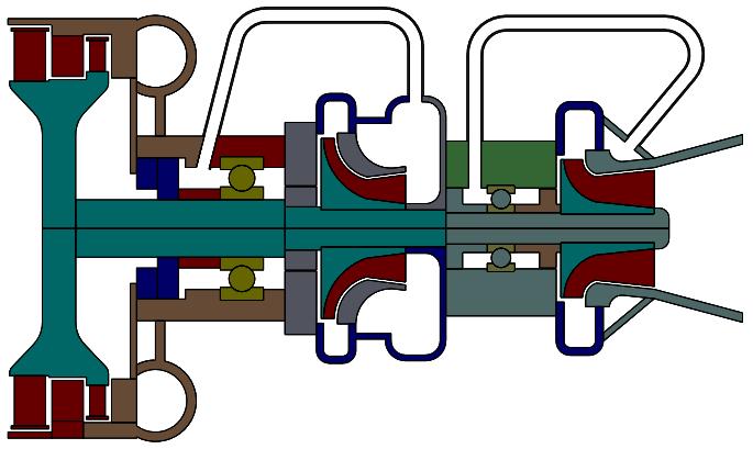
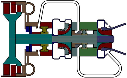
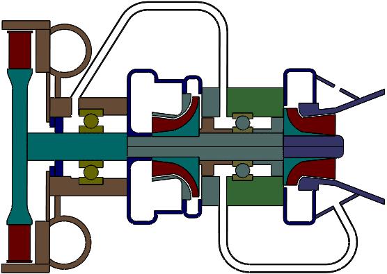

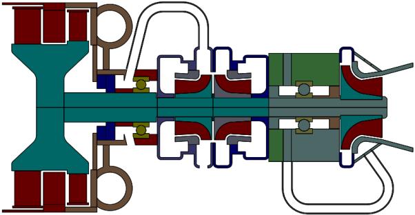
20 Simplified Turbopump Model Parameterization #1 #2 #3 #4 #5 #6 #7 SoftInWay: Turbomachinery Mastered 20
21 Calculations in AxSTREAM RotorDynamics Rotordynamics analysis is performed to determine bearing radial reaction bearing bearing Turbine RP1 pump LOX pump Rotordynamics model was generated for each turbopump configuration Geometry of rotor is transferred from the above presented CAD model Single flow LOX and RP1 pump bearing bearing - mass-inertia characteristics of turbine and pumps blades Turbine LOX pump RP1 pump Double flow LOX pump and single flow RP1 pump SoftInWay: Turbomachinery Mastered 21


22 Mass/Inertia Characteristics of Blades To define the mass and inertia momentum values of the entire pump and turbine wheel, the following automatic steps were performed: Export of blades.iges model of designed pump/turbine Import of.iges model and blades number to CAD tool Mass/inertia characteristics export from CAD tool 3 blades 9 blades Screw inducer Impeller Turbine SoftInWay: Turbomachinery Mastered 22
23 Secondary Flow System in AxSTREAM NET Tool The secondary flow system was modeled for each turbopump configuration to determine the fluid mass flow rate that provides bearing cooling sufficient for its reliable work. The geometry of the system is transferred from CAD model, BCs from cycle estimation. During the turbopump design process the fluid evaporation absence for each secondary flow path was controlled. The heat quantity due to bearing heating is determined by script calculation. Flow entrance Flow entrance Flow exit Flow exit Bearing Bearing RP1 secondary flow branch Heat supplying Elbow with recess Surface with rotation Annular channel LOX secondary flow branch Tube elements Chamber SoftInWay: Turbomachinery Mastered 23
24 Bearing Cooling Requirements and Leakage Amount Determination Friction power of bearings: where F = N fr = f F, ω Fa 2 + Fr 2 total bearing load; Fa axial load on bearing (from axial loading calculation); Fr radial load (from rotordynamics calculation); ω shaft rotational speed (maximal available ). Leakage value of MFR is clarified using condition: 2 G i G i 1 G i + G i 1 < where G i leakage MFR value at current iteration; G i 1 leakage MFR value at previous iteration; For the first iteration the leakage MFR is assigned arbitrarily. The second iteration and its subsequent is determined by secondary flow system calculation. If the conditional statement is not satisfied the modification of the respective seal is performed and the calculation is being repeated unit convergence. SoftInWay: Turbomachinery Mastered 24
25 Turbopump Design Results SoftInWay: Turbomachinery Mastered 25

26 Video of the part of the execution process SoftInWay: Turbomachinery Mastered 26
27 Integral Parameters of Turbopumps Parameter Unit #1 #2 #3 #4 #5 #6 #7 Turbine mass flow rate kg/s Axial load N Turbopump mass kg Turbopump length m Turbopump diameter m Shaft speed rpm Isp_engine s Maximum Isp_engine was obtained in configuration #6 Configuration #1 has 0.43 kg lighter TPU comparing to configuration #6 Assuming 200 s as a single firing duration configuration #1 will require 0.3 kg of total propellants mass more than configuration #6, which is less than the difference in turbopump mass Configuration #1 provides a better combination of Isp_engine and turbopump mass Utilization of a dual flow oxygen pump enables increased rotational speed and make configurations #6 and #7 compact SoftInWay: Turbomachinery Mastered 27
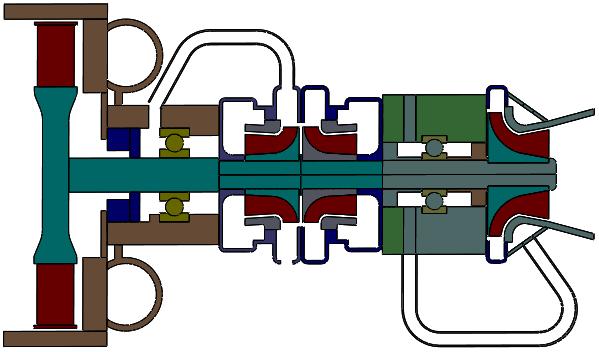
28 Configuration #1 Turbopump Preliminary Layout SoftInWay: Turbomachinery Mastered 28

29 Thrust Nozzle Preliminary Design Parameter Unit Magnitude Expansion ratio Throat radius m Exhaust radius m Nozzle length m 0.65 Nozzle controur - 90 % bell SoftInWay: Turbomachinery Mastered 29

30 Men-hours Preliminary Design Duration Assessment Preliminary engine design 240 times faster preliminary engine design without compromise in performance Dramatic reduction of labor and associated cost Shorter duration of engine development and entrance to the market provides substantial financial advantage Developed system Conventional SoftInWay: Turbomachinery Mastered 30
31 Conclusions SoftInWay: Turbomachinery Mastered 31
32 Conclusions 1. Taking into account the microsatellite launch trends and launch vehicles market analysis presented earlier in this presentation, we can see that the demand is significant and the state of the industry is becoming progressively more competitive. With this in mind, the development duration becomes extremely important in both minimizing launch costs and supplying the specific launcher quickly, for a specific need. Even the highest performing and cost-efficient vehicle can become useless if not supplied on time in such a competitive and dynamic market. 2. The consideration of launch vehicle breakdown by elements was presented and showed the significant potential for launch cost reduction by shortening the engine development duration which will lead to labor and facilities cost decrease. 3. The system for the design of a liquid rocket engine was developed, which allows automatic iterative execution of rocket engine cycle analysis and turbopump preliminary design, including fuel pump design, oxidizer pump design, turbine design, turbopump preliminary layout development, secondary flows simulation, bearings simulation, rotor dynamics and stress analysis. SoftInWay: Turbomachinery Mastered 32
33 Conclusions 4. The proposed design system is easily expandable, which provides the opportunity to perform thrust chamber preliminary design, gas generator design, plumbing routes, turbopump orientation and mounting configuration considerations, and even some more detailed calculations after preliminary design as a part of the presented algorithm which can reduce the duration of the liquid rocket engine detailed design phase as well. 5. The example of the developed system for preliminary design of a rocket engine, considering gas-generator cycle simulation and turbopump preliminary design of 7 different configurations was presented. It was determined that configuration #1 provides a better combination of Isp ( s) and turbopump mass (11.97 kg). The difference between thrust chamber Isp and engine Isp is 1.9 %. 6. The labor time for the preliminary design of the liquid rocket engine was reduced 240 times utilizing the developed approach. This time reduction not only decreases labor time but also decreases the associated facilities cost and enables supply of the engine in a shorter period which is extremely valuable in such a dynamic market. SoftInWay: Turbomachinery Mastered 33
34 Future Plans SoftInWay: Turbomachinery Mastered 34
35 Future Plans The proposed design system is easily expandable. It offers the opportunity to perform thrust chamber preliminary design, gas generator design, plumbing routes, turbopump orientation and mounting configurations considerations. After preliminary design, more detailed calculations can be performed as a part of the presented algorithm and reduce the duration of liquid rocket engine detailed design phase. The authors of the paper are planning to continue work in this direction and present the results in future papers. SoftInWay: Turbomachinery Mastered 35
36 Commercial Software Tools Utilized in the Study SoftInWay: Turbomachinery Mastered 36
37 Commercial Software Tools Utilized in the Study AxSTREAM for turbomachinery preliminary design AxSTREAM NET 1D hydraulic network analysis tool was used for leakage flow simulation AxSTREAM Rotor Dynamics and AxSTREAM Bearing were used for rotor dynamics and bearings simulation AxSTRESS was used for preliminary stress analysis of turbomachinery components AxSTREAM ION was utilized for the development of the turbopump preliminary design system, including operation flowchart design, optimization, integration of the off-the-shelf and custom software tools, and execution. SolidWorks was used for automatic generation of preliminary layout of turbopump and thrust chamber SoftInWay: Turbomachinery Mastered 37
38 Thank you for Your Attention SoftInWay: Turbomachinery Mastered 38
Review of iterative design approach Mass Estimating Relationships (MERs) Sample vehicle design analysis
 Sample vehicle design analysis") Review of iterative design approach (MERs) Sample vehicle design analysis 2005 David L. Akin - All rights reserved http://spacecraft.ssl.umd.edu The Spacecraft Design Process Akin s Laws of Spacecraft
Review of iterative design approach (MERs) Sample vehicle design analysis 2005 David L. Akin - All rights reserved http://spacecraft.ssl.umd.edu The Spacecraft Design Process Akin s Laws of Spacecraft
Lessons in Systems Engineering. The SSME Weight Growth History. Richard Ryan Technical Specialist, MSFC Chief Engineers Office
 National Aeronautics and Space Administration Lessons in Systems Engineering The SSME Weight Growth History Richard Ryan Technical Specialist, MSFC Chief Engineers Office Liquid Pump-fed Main Engines Pump-fed
FLEXIBLE, FAST AND HIGH FIDELITY APPROACH TO GTU PART-LOAD AND OFF-DESIGN PERFORMANCE PREDICTIONS
 TETS 2018, Dayton Convention Center, Dayton, Ohio, Sept. 10-13, 2018 FLEXIBLE, FAST AND HIGH FIDELITY APPROACH TO GTU PART-LOAD AND OFF-DESIGN PERFORMANCE PREDICTIONS Presenter: Co-Authors: Company: Dr.
Fundamentals of steam turbine systems
 Principles of operation Fundamentals of steam turbine systems - The motive power in a steam turbine is obtained by the rate of change in momentum of a high velocity jet of steam impinging on a curved blade
IAC-15-C4.3.1 JET INDUCER FOR A TURBO PUMP OF A LIQUID ROCKET ENGINE
 IAC-15-C4.3.1 JET INDUCER FOR A TURBO PUMP OF A LIQUID ROCKET ENGINE Martin Böhle Technical University Kaiserslautern, Germany, martin.boehle@mv.uni-kl.de Wolfgang Kitsche German Aerospace Center (DLR),
Development of a Low Cost Suborbital Rocket for Small Satellite Testing and In-Space Experiments
 Development of a Low Cost Suborbital Rocket for Small Satellite Testing and In-Space Experiments Würzburg, 2015-09-15 (extended presentation) Dr.-Ing. Peter H. Weuta Dipl.-Ing. Neil Jaschinski WEPA-Technologies
Civil Engineering Hydraulics. Radial Flow Devices
 Civil Engineering Hydraulics 2 3 Many rotary-flow devices such as centrifugal pumps and fans involve flow in the radial direction normal to the axis of rotation and are called radial- flow devices. 4 In
MARITIME AFTERNOON. Torben Ole Andersen. June 14, 2017 Aalborg University, Denmark
 MARITIME AFTERNOON HYDRAULICS Torben Ole Andersen June 14, 2017 Aalborg University, Denmark Agenda Marine Propellers Digital Hydraulics in a Hydraulic Winch Secondary Control in of Multi -Chamber Cylinders
Mass Estimating Relations
 Review of iterative design approach (MERs) Sample vehicle design analysis 1 2009 David L. Akin - All rights reserved http://spacecraft.ssl.umd.edu Akin s Laws of Spacecraft Design - #3 Design is an iterative
Design and Test of Transonic Compressor Rotor with Tandem Cascade
 Proceedings of the International Gas Turbine Congress 2003 Tokyo November 2-7, 2003 IGTC2003Tokyo TS-108 Design and Test of Transonic Compressor Rotor with Tandem Cascade Yusuke SAKAI, Akinori MATSUOKA,
Low Cost Propulsion Systems for Launch-, In Space- and SpaceTourism Applications
 Low Cost Propulsion Systems for Launch-, In Space- and SpaceTourism Applications Space Propulsion (Rome, 02 06/05/2016) Dr.-Ing. Peter H. Weuta Dipl.-Ing. Neil Jaschinski WEPA-Technologies GmbH (Germany)
AN OPTIMIZED PROPULSION SYSTEM FOR Soyuz/ST
 1 RD-0124 AN OPTIMIZED PROPULSION SYSTEM FOR Soyuz/ST Versailles, May 14,2002 Starsem Organization 2 35% 25% 15% 25% 50-50 European-Russian joint venture providing Soyuz launch services for the commercial
Thermomechanical Analysis of the Turbo-Compressor Sliding Bearing Mount Units
 9 th International LS-DYNA Users Conference Simulation Technology (3) Thermomechanical Analysis of the Turbo-Compressor Sliding Bearing Mount Units M. Petrushina, S. Klambozki, O. Tchij Minsk, Belarus,
P. Teufel and A. Böhmer, ABB Turbo Systems, SIMULIA Customer Conference Thrust Collar Bearing Optimization using Isight
 P. Teufel and A. Böhmer, ABB Turbo Systems, SIMULIA Customer Conference 2012 Thrust Collar Bearing Optimization using Isight May 23, 2012 Thrust Collar Bearing Optimization Using Isight Contents Turbocharging:
Additively Manufactured Propulsion System
 Additively Manufactured Propulsion System Matthew Dushku Experimental Propulsion Lab 47 South 200 East Providence Utah, 84332 Mdushku@experimentalpropulsionlab.com Small Satellite Conference, Logan UT
Propeller blade shapes
 31 1 Propeller blade shapes and Propeller Tutorials 2 Typical Propeller Blade Shape 3 M Flight M. No. Transonic Propeller Airfoil 4 Modern 8-bladed propeller with transonic airfoils near the tip and swept
R&D on Environment-Friendly, Electronically Controlled Diesel Engine
 20000 M4.2.2 R&D on Environment-Friendly, Electronically Controlled Diesel Engine (Electronically Controlled Diesel Engine Group) Nobuyasu Matsudaira, Koji Imoto, Hiroshi Morimoto, Akira Numata, Toshimitsu
Mass Estimating Relations
 Review of iterative design approach (MERs) Sample vehicle design analysis 1 2013 David L. Akin - All rights reserved http://spacecraft.ssl.umd.edu Akin s Laws of Spacecraft Design - #3 Design is an iterative
The Enhanced Platform
 Power Generation The Enhanced Platform The Next Generation of Industrial Steam Turbines www.siemens.com / energy / steamturbines Advanced Steam Turbine Design Figure 1: Enhanced Platform Design The Enhanced
Scroll Compressor Oil Pump Analysis
 IOP Conference Series: Materials Science and Engineering PAPER OPEN ACCESS Scroll Compressor Oil Pump Analysis To cite this article: S Branch 2015 IOP Conf. Ser.: Mater. Sci. Eng. 90 012033 View the article
Extremely High Load Capacity Tapered Roller Bearings
 New Product Extremely High Load Capacity Tapered Roller Bearings Takashi UENO Tomoki MATSUSHITA Standard tapered roller bearing Extreme high load capacity bearing NTN developed a tapered roller bearing
Tilting Pad Journal Bearings
 Tilting Pad Journal Bearings Types W140 and W141 Diameter Range 40 355 mm Standard GTW Tilting Pad Journal Bearings type W140 with 4-pads and W141 with 5-pads. These bearings are used in high speed machines,
Electric Drive - Magnetic Suspension Rotorcraft Technologies
 Electric Drive - Suspension Rotorcraft Technologies William Nunnally Chief Scientist SunLase, Inc. Sapulpa, OK 74066-6032 wcn.sunlase@gmail.com ABSTRACT The recent advances in electromagnetic technologies
Fig 2: Grid arrangements for axis-symmetric Rocket nozzle.
 CFD Analysis of Rocket-Ramjet Combustion Chamber 1 Ms. P.Premalatha, Asst. Prof., PSN College of Engineering and Technology, Tirunelveli. 1prema31194@gmail.com 1 +91-90475 26413 2 Ms. T. Esakkiammal, Student,
Use of Flow Network Modeling for the Design of an Intricate Cooling Manifold
 Use of Flow Network Modeling for the Design of an Intricate Cooling Manifold Neeta Verma Teradyne, Inc. 880 Fox Lane San Jose, CA 94086 neeta.verma@teradyne.com ABSTRACT The automatic test equipment designed
APPLICATION OF STAR-CCM+ TO TURBOCHARGER MODELING AT BORGWARNER TURBO SYSTEMS
 APPLICATION OF STAR-CCM+ TO TURBOCHARGER MODELING AT BORGWARNER TURBO SYSTEMS BorgWarner: David Grabowska 9th November 2010 CD-adapco: Dean Palfreyman Bob Reynolds Introduction This presentation will focus
SMall Innovative Launcher for Europe: results of the H2020 project SMILE. Leo Timmermans, NLR І 2 October 2018
 SMall Innovative Launcher for Europe: results of the H2020 project SMILE Leo Timmermans, NLR І 2 October 2018 Problem (and opportunity) 2 Problem (and opportunity) SmallSat Launch Market to Soar Past $62
Motor-CAD End Winding Spray Cooling Model
 Motor-CAD End Winding Spray Cooling Model Description Motor spray cooling is where the end winding is cooled by passing a fluid down the shaft and then firing it at the end winding through nozzles at the
Development of Low Cost Propulsion Systems for Launchand In Space Applications
 Reinventing Space Conference BIS-RS-2015-36 Development of Low Cost Propulsion Systems for Launchand In Space Applications Peter H. Weuta WEPA-Technologies GmbH Neil Jaschinski WEPA-Technologies GmbH 13
Development of Low-thrust Thruster with World's Highest Performance Contributing to Life Extension of Artificial Satellites
 Development of Low-thrust Thruster with World's Highest Performance Contributing to Life Extension of Artificial Satellites 40 NOBUHIKO TANAKA *1 DAIJIRO SHIRAIWA *1 TAKAO KANEKO *2 KATSUMI FURUKAWA *3
CFD Analysis on a Different Advanced Rocket Nozzles
 International Journal of Engineering and Advanced Technology (IJEAT) CFD Analysis on a Different Advanced Rocket Nozzles Munipally Prathibha, M. Satyanarayana Gupta, Simhachalam Naidu Abstract The reduction
Heat Exchangers (Chapter 5)
") Heat Exchangers (Chapter 5) 2 Learning Outcomes (Chapter 5) Classification of heat exchangers Heat Exchanger Design Methods Overall heat transfer coefficient LMTD method ε-ntu method Heat Exchangers Pressure
Heat Exchangers (Chapter 5) 2 Learning Outcomes (Chapter 5) Classification of heat exchangers Heat Exchanger Design Methods Overall heat transfer coefficient LMTD method ε-ntu method Heat Exchangers Pressure
VARIABLE DISPLACEMENT OIL PUMP IMPROVES TRACKED VEHICLE TRANSMISSION EFFICIENCY
 2018 NDIA GROUND VEHICLE SYSTEMS ENGINEERING AND TECHNOLOGY SYMPOSIUM POWER & MOBILITY (P&M) TECHNICAL SESSION AUGUST 7-9, 2018 NOVI, MICHIGAN VARIABLE DISPLACEMENT OIL PUMP IMPROVES TRACKED VEHICLE TRANSMISSION
AUTOMATED SELECTION OF THE MATERIAL A FAN BLADE PS-90A
 AUTOMATED SELECTION OF THE MATERIAL A FAN BLADE PS-90A D. A. Akhmedzyanov, A. E. Kishalov, K. V. Markina USATU Ufa State Aviation Technical University, Russia Keywords: GTE, fan blade, composite material,
Liquid Rocket Engine TCA
 Liquid Rocket Engine TCA TCA -1 Thrust Chamber Assembly (TCA) TCA=combustion chamber+nozzle Design goals produce desired thrust with high efficiency high combustion efficiency and uniformity into nozzle
Idealizations Help Manage Analysis of Complex Processes
 8 CHAPTER Gas Power Cycles 8-1 Idealizations Help Manage Analysis of Complex Processes The analysis of many complex processes can be reduced to a manageable level by utilizing some idealizations (fig.
MARIM Steam Turbines. Engineering the Future - since MAN Diesel & Turbo
 MARIM Steam Turbines Engineering the Future - since 1758. MAN Diesel & Turbo Introduction MAN has over a century of experience in manufacturing steam turbines for industrial applications and utilities
USA FALCON 1. Fax: (310) Telephone: (310) Fax: (310) Telephone: (310) Fax: (310)
 Telephone: (310) Fax: (310) Telephone: (310) Fax: (310)") 1. IDENTIFICATION 1.1 Name FALCON 1 1.2 Classification Family : FALCON Series : FALCON 1 Version : FALCON 1 Category : SPACE LAUNCH VEHICLE Class : Small Launch Vehicle (SLV) Type : Expendable Launch Vehicle
1. IDENTIFICATION 1.1 Name FALCON 1 1.2 Classification Family : FALCON Series : FALCON 1 Version : FALCON 1 Category : SPACE LAUNCH VEHICLE Class : Small Launch Vehicle (SLV) Type : Expendable Launch Vehicle
ME2301 THERMAL ENGINEERING L T P C OBJECTIVE:
 ME2301 THERMAL ENGINEERING L T P C 3 1 0 4 OBJECTIVE: To integrate the concepts, laws and methodologies from the first course in thermo dynamics into analysis of cyclic processes To apply the thermodynamic
APPLICATION OF A NEW TYPE OF AERODYNAMIC TILTING PAD JOURNAL BEARING IN POWER GYROSCOPE
 Colloquium DYNAMICS OF MACHINES 2012 Prague, February 7 8, 2011 CzechNC APPLICATION OF A NEW TYPE OF AERODYNAMIC TILTING PAD JOURNAL BEARING IN POWER GYROSCOPE Jiří Šimek Abstract: New type of aerodynamic
SABRE FOR HYPERSONIC & SPACE ACCESS PLATFORMS
 SABRE FOR HYPERSONIC & SPACE ACCESS PLATFORMS Mark Thomas Chief Executive Officer 12 th Appleton Space Conference RAL Space, 1 st December 2016 1 Reaction Engines Limited REL s primary focus is developing
Al- Ameen Engg. College. Fluid Machines. Prepared by: AREEF A AP/ ME AL AMEEN ENGINEERING COLLEGE Shoranur.
 Fluid Machines Prepared by: AREEF A AP/ ME AL AMEEN ENGINEERING COLLEGE Shoranur Classification of hydraulic machines HYDROULIC MACHINES (I) Hydraulic Turbines A hydraulic machine which converts hydraulic
CHAPTER 4 MODELING OF PERMANENT MAGNET SYNCHRONOUS GENERATOR BASED WIND ENERGY CONVERSION SYSTEM
 47 CHAPTER 4 MODELING OF PERMANENT MAGNET SYNCHRONOUS GENERATOR BASED WIND ENERGY CONVERSION SYSTEM 4.1 INTRODUCTION Wind energy has been the subject of much recent research and development. The only negative
Single-phase Coolant Flow and Heat Transfer
 22.06 ENGINEERING OF NUCLEAR SYSTEMS - Fall 2010 Problem Set 5 Single-phase Coolant Flow and Heat Transfer 1) Hydraulic Analysis of the Emergency Core Spray System in a BWR The emergency spray system of
PIPINGSOLUTIONS, INC.
 Piping Stress Analysis Where do I start? The following information will take you step-by-step through the logic of the data collection effort that should occur prior to beginning to model a piping system
Ground Test Demonstrator Engine Boost Turbopumps Design and Development
 41st AIAA/ASME/SAE/ASEE Joint Propulsion Conference & Exhibit 1-13 July 25, Tucson, Arizona AIAA 25-3945 Ground Test Demonstrator Engine Boost Turbopumps Design and Development Y. Demyanenko *, A. Dmitrenko,
Welcome to Aerospace Engineering
 Welcome to Aerospace Engineering DESIGN-CENTERED INTRODUCTION TO AEROSPACE ENGINEERING Notes 5 Topics 1. Course Organization 2. Today's Dreams in Various Speed Ranges 3. Designing a Flight Vehicle: Route
Suitability of reusability for a Lunar re-supply system
 www.dlr.de Chart 1 Suitability of reusability for a Lunar re-supply system Etienne Dumont Space Launcher Systems Analysis (SART) Institut of Space Systems, Bremen, Germany Etienne.dumont@dlr.de IAC 2016
Rocket 101. IPSL Space Policy & Law Course. Andrew Ratcliffe. Head of Launch Systems Chief Engineers Team
 Rocket 101 IPSL Space Policy & Law Course Andrew Ratcliffe Head of Launch Systems Chief Engineers Team Contents Background Rocket Science Basics Anatomy of a Launch Vehicle Where to Launch? Future of Access
CHAPTER 3 DESIGN OF THE LIMITED ANGLE BRUSHLESS TORQUE MOTOR
 33 CHAPTER 3 DESIGN OF THE LIMITED ANGLE BRUSHLESS TORQUE MOTOR 3.1 INTRODUCTION This chapter presents the design of frameless Limited Angle Brushless Torque motor. The armature is wound with toroidal
AERODYNAMIC DESIGN OPTIMIZATION OF A 200 KW-CLASS RADIAL INFLOW SUPERCRITICAL CARBON DIOXIDE TURBINE
 Proceedings of Shanghai 2017 Global Power and Propulsion Forum 30 th October 1 st November, 2017 http://www.gpps.global GPPS-2017-0109 AERODYNAMIC DESIGN OPTIMIZATION OF A 200 KW-CLASS RADIAL INFLOW SUPERCRITICAL
November 8, 2018 GAS TURBINE ENGINE SECONDARY FLOW SYSTEMS
 November 8, 2018 GAS TURBINE ENGINE SECONDARY FLOW SYSTEMS Agenda 1 What is Secondary Flow? Purpose for the Secondary Flow Systems Chargeable Vs Nonchargeable Flows Seals Selection and Leakage Effects
Design of a Custom Vortex generator Optimization of Vehicle Drag and Lift Characteristics
 Design of a Custom Vortex generator Optimization of Vehicle Drag and Lift Characteristics Naveen. S 1, Vipin Prakkash 2, Sukanth Kannan 3 1, 2, 3 Senior Engineer, Sharda Motor Industries Limited R&D, Chennai,
ME 466 PERFORMANCE OF ROAD VEHICLES 2016 Spring Homework 3 Assigned on Due date:
 PROBLEM 1 For the vehicle with the attached specifications and road test results a) Draw the tractive effort [N] versus velocity [kph] for each gear on the same plot. b) Draw the variation of total resistance
CONTENTS Duct Jet Propulsion / Rocket Propulsion / Applications of Rocket Propulsion / 15 References / 25
 CONTENTS PREFACE xi 1 Classification 1.1. Duct Jet Propulsion / 2 1.2. Rocket Propulsion / 4 1.3. Applications of Rocket Propulsion / 15 References / 25 2 Definitions and Fundamentals 2.1. Definition /
Theory of turbo machinery / Turbomaskinernas teori. Chapter 4
 Teory of turbo macinery / Turbomaskinernas teori Capter 4 Axial-flow turbines FIG. 4.1. Large low pressure steam turbine (Siemens) Axial-flow turbines FIG. 4.. Turbine module of a modern turbofan jet engine
NEWAC Overall Specification, Assessment and Concept Optimization
 NEWAC Overall Specification, Assessment and Concept Optimization Andrew Rolt, Rolls-Royce plc. with contributions from: Konstantinos Kyprianidis, Cranfield University; Stefan Donnerhack and Wolfgang Sturm,
Development of Internationally Competitive Solid Rocket Booster for H3 Launch Vehicle
 Development of Internationally Competitive Solid Rocket Booster for H3 Launch Vehicle YANAGISAWA Masahiro : Space Launch Vehicle Project Office, Rocket Systems Department, IHI AEROSPACE Co., Ltd. KISHI
Design Rules and Issues with Respect to Rocket Based Combined Cycles
 Respect to Rocket Based Combined Cycles Tetsuo HIRAIWA hiraiwa.tetsuo@jaxa.jp ABSTRACT JAXA Kakuda space center has been studying rocket based combined cycle engine for the future space transportation
Development of High Performance 3D Scroll Compressor
 Purdue University Purdue e-pubs International Compressor Engineering Conference School of Mechanical Engineering 2006 Development of High Performance 3D Scroll Compressor Taichi Tateishi Mitsubishi Heavy
EXTENDED GAS GENERATOR CYCLE
 EXTENDED GAS GENERATOR CYCLE FOR RE-IGNITABLE CRYOGENIC ROCKET PROPULSION SYSTEMS F. Dengel & W. Kitsche Institute of Space Propulsion German Aerospace Center, DLR D-74239 Hardthausen, Germany ABSTRACT
WINTER 14 EXAMINATION
 WINTER 14 EXAMINATION Subject Code: 17413(EME) Model Answer Important Instructions to examiners: 1) The answers should be examined by key words and not as word-to-word as given in the model answer scheme.
Aerospace Propulsion Systems
 Brochure More information from http://www.researchandmarkets.com/reports/1288672/ Aerospace Propulsion Systems Description: Aerospace Propulsion Systems is a unique book focusing on each type of propulsion
ReachMars 2024 A Candidate Large-Scale Technology Demonstration Mission as a Precursor to Human Mars Exploration
 ReachMars 2024 A Candidate Large-Scale Technology Demonstration Mission as a Precursor to Human Mars Exploration 1 October 2014 Toronto, Canada Mark Schaffer Senior Aerospace Engineer, Advanced Concepts
Preliminary Design Study of Main Rocket Engine for SpaceLiner High-Speed Passenger Transportation Concept
 Preliminary Design Study of Main Rocket Engine for SpaceLiner High-Speed Passenger Transportation Concept By Ryoma Yamashiro 1) and Martin Sippel 2) 1) Space Transportation Mission Directorate, JAXA, Tsukuba,
CONCEPT STUDY OF AN ARES HYBRID-OS LAUNCH SYSTEM
 CONCEPT STUDY OF AN ARES HYBRID-OS LAUNCH SYSTEM AIAA-2006-8057 14th AIAA/AHI Space Planes and Hypersonic Systems and Technologies Conference 06-09 November 2006, Canberra, Australia Revision A 07 November
Year I. TRC-SEAL Luis San Andrés. Weilian Shan Graduate Research Assistant. May rd Turbomachinery Research Consortium Meeting
 33 rd Turbomachinery Research Consortium Meeting Predictions vs. Test Results for Leakage and Force Coefficients of a Fully Partitioned Pocket Damper Seal and a Labyrinth Seal Limitations of the Current
Study on Flow Fields in Variable Area Nozzles for Radial Turbines
 Vol. 4 No. 2 August 27 Study on Fields in Variable Area Nozzles for Radial Turbines TAMAKI Hideaki : Doctor of Engineering, P. E. Jp, Manager, Turbo Machinery Department, Product Development Center, Corporate
Scroll Expander for Carbon Dioxide Cycle
 Purdue University Purdue e-pubs International Refrigeration and Air Conditioning Conference School of Mechanical Engineering 26 Scroll Expander for Carbon Dioxide Cycle Detlef Westphalen John Dieckmann
Engine Performance Analysis
 Engine Performance Analysis Introduction The basics of engine performance analysis The parameters and tools used in engine performance analysis Introduction Parametric cycle analysis: Independently selected
HERCULES-2 Project. Deliverable: D8.8
 HERCULES-2 Project Fuel Flexible, Near Zero Emissions, Adaptive Performance Marine Engine Deliverable: D8.8 Study an alternative urea decomposition and mixer / SCR configuration and / or study in extended
Multi Body Dynamic Analysis of Slider Crank Mechanism to Study the effect of Cylinder Offset
 Multi Body Dynamic Analysis of Slider Crank Mechanism to Study the effect of Cylinder Offset Vikas Kumar Agarwal Deputy Manager Mahindra Two Wheelers Ltd. MIDC Chinchwad Pune 411019 India Abbreviations:
STUDY ON COMPACT HEAT EXCHANGER FOR VEHICULAR GAS TURBINE ENGINE
 Proceedings of Fifth International Conference on Enhanced, Compact and Ultra-Compact Heat Exchangers: Science, Engineering and Technology, Eds. R.K. Shah, M. Ishizuka, T.M. Rudy, and V.V. Wadekar, Engineering
Variable Valve Drive From the Concept to Series Approval
 Variable Valve Drive From the Concept to Series Approval New vehicles are subject to ever more stringent limits in consumption cycles and emissions. At the same time, requirements in terms of engine performance,
Vehicle Dynamic Simulation Using A Non-Linear Finite Element Simulation Program (LS-DYNA)
") Vehicle Dynamic Simulation Using A Non-Linear Finite Element Simulation Program (LS-DYNA) G. S. Choi and H. K. Min Kia Motors Technical Center 3-61 INTRODUCTION The reason manufacturers invest their time
Vehicle Dynamic Simulation Using A Non-Linear Finite Element Simulation Program (LS-DYNA) G. S. Choi and H. K. Min Kia Motors Technical Center 3-61 INTRODUCTION The reason manufacturers invest their time
Gas exchange process for IC-engines: poppet valves, valve timing and variable valve actuation
 Gas exchange process for IC-engines: poppet valves, valve timing and variable valve actuation Topics Analysis of the main parameters influencing the volumetric efficiency in IC engines: - Valves and valve
ABSTRACT 1. INTRODUCTION
 1260, Page 1 Patrice BONNEFOI 1, Philippe DUGAST 2, Jean de BERNARDI 3 1 Danfoss CC, Advanced Technology, Trévoux, France 33 (0)4 74 00 28 29, p.bonnefoi@danfoss.com 2 Danfoss CC, Advanced Technology,
Mass Estimating Relations
 Lecture #05 - September 11, 2018 Review of iterative design approach (MERs) Sample vehicle design analysis 1 2018 David L. Akin - All rights reserved http://spacecraft.ssl.umd.edu Akin s Laws of Spacecraft
ASABOOSTER CD005 Conceptual Design Study for an Asaspace Launch Capability Version 0.04
 ASABOOSTER CD005 Conceptual Design Study for an Asaspace Launch Capability Version 0.04 by Ed LeBouthillier 1 of 26 Forward In a previous conceptual design study, Asabooster CD004, I examined a vertical
Turbostroje 2015 Návrh spojení vysokotlaké a nízkotlaké turbíny. Turbomachinery 2015, Design of HP and LP turbine connection
 Turbostroje 2015 Turbostroje 2015 Návrh spojení vysokotlaké a nízkotlaké turbíny Turbomachinery 2015, Design of HP and LP turbine connection J. Hrabovský 1, J. Klíma 2, V. Prokop 3, M. Komárek 4 Abstract:
Chapter 9 GAS POWER CYCLES
 Thermodynamics: An Engineering Approach, 6 th Edition Yunus A. Cengel, Michael A. Boles McGraw-Hill, 2008 Chapter 9 GAS POWER CYCLES Copyright The McGraw-Hill Companies, Inc. Permission required for reproduction
KINGS COLLEGE OF ENGINEERING DEPARTMENT OF MECHANICAL ENGINEERING. Question Bank. UNIT-I THERMODYNAMIC CYCLES Part-A (2 Marks)
") KINGS COLLEGE OF ENGINEERING DEPARTMENT OF MECHANICAL ENGINEERING Question Bank Sub. Code/Name: ME1351 - THERMAL ENGINEERING Year/Sem: III/VI 1. What is a thermodynamic cycle? UNIT-I THERMODYNAMIC CYCLES
KINGS COLLEGE OF ENGINEERING DEPARTMENT OF MECHANICAL ENGINEERING Question Bank Sub. Code/Name: ME1351 - THERMAL ENGINEERING Year/Sem: III/VI 1. What is a thermodynamic cycle? UNIT-I THERMODYNAMIC CYCLES
Innovative Centrifugal Compressor Design
 Innovative Centrifugal Compressor Design L. Tarnowski TURBOMECA groupe SAFRAN INTRODUCTION SP2 : IRA (Intercooled Recuperative Aero-engine) Task 2.2.5 HP Centrifugal Compressor Design The challenge is
Monopropellant Micro Propulsion system for CubeSats
 Monopropellant Micro Propulsion system for CubeSats By Chris Biddy 174 Suburban Rd Suite 120 San Luis Obispo CA 93401 (805) 549 8200 chris@stellar exploration.com Introduction High Performance CubeSat
Numerical simulation of detonation inception in Hydrogen / air mixtures
 Numerical simulation of detonation inception in Hydrogen / air mixtures Ionut PORUMBEL COMOTI Non CO2 Technology Workshop, Berlin, Germany, 08.03.2017 09.03.2017 Introduction Objective: Development of
IAC-04-IAF-S.2.06 NEW PROPELLANT IGNITION SYSTEM IN LV SOYUZ ROCKET ENGINE CHAMBERS
 IAC-04-IAF-S.2.06 NEW PROPELLANT IGNITION SYSTEM IN LV SOYUZ ROCKET ENGINE CHAMBERS Igor Yu. Fatuev, Anatoly A.Ganin NPO Energomash named after academician V.P.Glushko, Russia, 141400, Khimky, Moscow area,
INTEGRATED HYDRO-MECHANICAL SIMULATION OF A CAM-ROCKER ARM-UNIT INJECTOR SYSTEM TO ADDRESS NOISE AND VIBRATION ISSUES
 GT-Suite Users Conference Frankfurt, Germany, October 10 th 2005 INTEGRATED HYDRO-MECHANICAL SIMULATION OF A CAM-ROCKER ARM-UNIT INJECTOR SYSTEM TO ADDRESS NOISE AND VIBRATION ISSUES R. HAM, H. FESSLER
FINAL PRESENTATION Purdue University Andrea Vacca 4/13/2018
 FINAL PRESENTATION Purdue University Andrea Vacca 4/13/2018 PRESENTATION OVERVIEW The Team Bicycle Design Hydraulic design AMESim simulation and optimization Experimental and simulation results Mechanical
Chapter 6. Supercharging
 SHROFF S. R. ROTARY INSTITUTE OF CHEMICAL TECHNOLOGY (SRICT) DEPARTMENT OF MECHANICAL ENGINEERING. Chapter 6. Supercharging Subject: Internal Combustion Engine 1 Outline Chapter 6. Supercharging 6.1 Need
Design and Analysis of a Two-Stage Anti-Tank Missile
 Design and Analysis of a Two-Stage Anti-Tank Missile by David Qi Zhang A Project Submitted to the Graduate Faculty of Rensselaer Polytechnic Institute in Partial Fulfillment of the Requirements for the
CubeSat Advanced Technology Propulsion System Concept
 SSC14-X-3 CubeSat Advanced Technology Propulsion System Concept Dennis Morris, Rodney Noble Aerojet Rocketdyne 8900 DeSoto Ave., Canoga Park, CA 91304; (818) 586-1503 Dennis.Morris@rocket.com ABSTRACT
Use of Simpack at the DaimlerChrysler Commercial Vehicles Division
 Use of Simpack at the DaimlerChrysler Commercial Vehicles Division Dr. Darko Meljnikov 22.03.2006 Truck Product Creation (4P) Content Introduction Driving dynamics and handling Braking systems Vehicle
TURBOPUMPS, ENGINE DESIGN, ENGINE CONTROLS, CALIBRATION,
 CHAPTER 10 TURBOPUMPS, ENGINE DESIGN, ENGINE CONTROLS, CALIBRATION, INTEGRATION, AND OPTIMIZATION In this chapter we first discuss a complex high-precision, high-speed, rotating subsystem, namely the turbopump.
DESIGN AND ANALYSIS OF TUBULAR CHASSIS OF GO-KART
 DESIGN AND ANALYSIS OF TUBULAR CHASSIS OF GO-KART Prashant Thakare 1, Rishikesh Mishra 2, Kartik Kannav 3, Nikunj Vitalkar 4, Shreyas Patil 5, Snehal Malviya 6 1 UG Students, Department of Mechanical Engineering,
Modeling and Optimization of Trajectory-based HCCI Combustion
 018 CCEFP IEC Summit at the University of Minnesota Modeling and Optimization of Trajectory-based HCCI Combustion 018 CSSCI Spring Technical Meeting Chen Zhang Abhinav Tripathi Professor Zongxuan Sun Department
RDT&E BUDGET ITEM JUSTIFICATION SHEET (R-2 Exhibit) June 2001
 June 2001") PE NUMBER: 0603302F PE TITLE: Space and Missile Rocket Propulsion BUDGET ACTIVITY RDT&E BUDGET ITEM JUSTIFICATION SHEET (R-2 Exhibit) June 2001 PE NUMBER AND TITLE 03 - Advanced Technology Development
PE NUMBER: 0603302F PE TITLE: Space and Missile Rocket Propulsion BUDGET ACTIVITY RDT&E BUDGET ITEM JUSTIFICATION SHEET (R-2 Exhibit) June 2001 PE NUMBER AND TITLE 03 - Advanced Technology Development
SAE Baja - Drivetrain
 SAE Baja - Drivetrain By Ricardo Inzunza, Brandon Janca, Ryan Worden Team 11 Engineering Analysis Document Submitted towards partial fulfillment of the requirements for Mechanical Engineering Design I
High aspect ratio for high endurance. Mechanical simplicity. Low empty weight. STOVL or STOL capability. And for the propulsion system:
 Idealized tilt-thrust (U) All of the UAV options that we've been able to analyze suffer from some deficiency. A diesel, fixed-wing UAV could possibly satisfy the range and endurance objectives, but integration
Chapter 9 GAS POWER CYCLES
 Thermodynamics: An Engineering Approach Seventh Edition in SI Units Yunus A. Cengel, Michael A. Boles McGraw-Hill, 2011 Chapter 9 GAS POWER CYCLES Mehmet Kanoglu University of Gaziantep Copyright The McGraw-Hill
IPRO 317-VTOL Aircraft for the Masses
 IPRO 317-VTOL Aircraft for the Masses Jesse Collins Brandon Honore Julia Northrop Neal Patel Kabir Metha Douglas Elkins Sean McCann Benjamin Smith Akash Garg Vikram Kumar Allow Us To Introduce VTOL Vertical