SR-71 PROPULSION SYSTEM P&W J58 ENGINE (JT11D-20) ONE OF THE BEST JET ENGINES EVER BUILT
|
|
|
- Gloria Gaines
- 6 years ago
- Views:
Transcription
1 SR-71 PROPULSION SYSTEM P&W J58 ENGINE (JT11D-20) PETER LAW ONE OF THE BEST JET ENGINES EVER BUILT
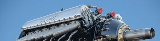
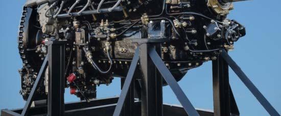
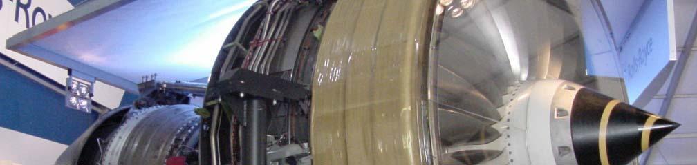
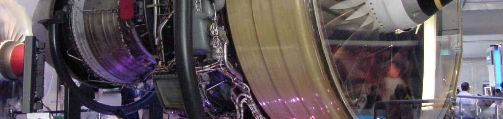

2 Rolls-Royce Milestone Engines Merlin Conway W2B Welland Derwent Trent
3
4
5
6
7 SR-71 GENERAL CHARACTERISTICS Two Place High-Altitude High-Speed Reconnaissance Aircraft Developed in Early 1960s By Kelly Johnson, Lockheed "Skunk Works" In Burbank, California (Advanced Development Projects - ADP) Delta Wing Configuration Crew Of Two: Pilot And Reconnaissance Systems Officer (RSO) Seated In Tandem Arrangement Inflight Refueling Capability - Crew Endurance is Limit Aircraft Length is 107 Feet, Wing Span Is 55 Feet, Height is 18 Feet Takeoff Weight is 140,000 Pounds; 80,000+ Pounds Of Fuel 93% Of Vehicle Structure And Skin is Titanium Aircraft Series Known As "Blackbirds"
8 SR-71 PERFORMANCE CHARACTERISTICS Cruising i Altitude Is Between 74,000 And 85,000 Feet Cruising Speed Is Mach 3.2+, MPH, Feet/Sec Range Is 3,000 Miles, 15,000 Miles with Refueling Total Flight Time Of All "Blackbird" Aircraft: 53,000+ Hours Total Time Above Mach 3.0: 11,000+ Hours (22 Million Miles) Powered By Two Pratt & Whitney J58 Turbojet Engines, Each With The Power Of The Queen Mary Vehicle Was Designed With Radar Signature Reduction Techniques
9 SR-71 FLIGHT RECORDS Sustained Speed In Level Flight 7/28/76 2, mph Sustained Altitude In Level Flight 7/28/76 85,069 feet New York To London 9/1/ mph 1 Hr 54 Min 32 Sec London To Los Angeles 9/13/ mph 3 Hr 47 Min 39 Sec USA Coast To Coast 3/6/ mph 1 Hr 7 Min Sec Los Angeles To Washington3/6/ mph 1 Hr 4 Min Sec Kansas City To Washington 3/6/ mph 24 Min Sec St. Louis To Cincinnati 3/6/ mph 8 Min Sec NAA Official i Data
10
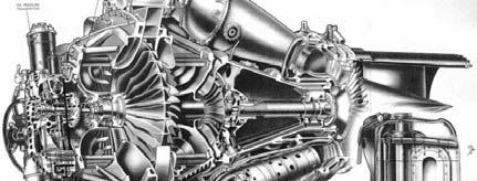
11 GENERAL COMMENTS ON SR-71 PROPULSION SYSTEM THE SR-71 WAS THE FINEST AIR BREATHING JET AIRCRAFT EVER DEVELOPED, BUILT, AND FLOWN. DESIGNED TO FLY AT MACH 3.2, WIND TUNNEL TESTED TO MACH 3.5, AND FLEW MISSIONS AT MACH 3.3+, 3+ AT ALTITUDES OF 86,000+ FEET. THE P&W J58 (JT11D-20) HAD THE POWER OF THE QUEEN MARY; STARTED LIFE WITH 30,000 POUNDS OF THRUST, AND ENDED WITH 34,000 POUNDS. THE PROPULSION SYSTEM CONSISTED OF THE AIR INLET AND AIR FLOW CONTROL SYSTEM, THE J58 ENGINE, AND THE EXHAUST NOZZLE ASSEMBLY (PART OF THE AIRFRAME). THE IMPORTANT FEATURES OF EACH WILL BE BRIEFLY COVERED, AS EACH PART WAS CRITICAL FOR PROPER OPERATION OF THE INTEGRATED PROPULSION SYSTEM. AT MACH 3.2, 54% OF THE THRUST WAS PROVIDED BY THE INLET (DIFFERENTIAL PRESSURE BETWEEN EXTERNAL AND INTERNAL SURFACES OF THE INLET SPIKE), 17% BY THE ENGINE, AND 29% BY THE EJECTOR. ENGINE ACTED AS A GAS GENERATOR. ENGINE OPERATES FROM 4,000 RPM (IDLE) TO 7,400 RPM (MAX).
12
13 THE ENGINE THE ENGINE IS THE PRATT AND WHITNEY JT11D-20, DESIGNATED J58 BY THE MILITARY ENGINE IS A SINGLE-SPOOL, AFTERBURNING TURBO-JET, WITH A 4 th -STAGE BLEED BYPASS DUCTING AIR INTO THE AFTERBURNER BLEED SYSTEM IS OPERATED AT HIGH MACH NUMBERS TO PROVIDE INCREASED COMPRESSOR STALL MARGIN BLEED AIR RE-ENTERS THE ENGINE AHEAD OF THE AFTERBURNER WHERE THE AIR IS USED FOR COOLING AND INCREASED THRUST AUGMENTATION BYPASS AIRFLOW IS 20% OF TOTAL FLOW INTO ENGINE ENGINE RPM IS MAINTAINED BY MODULATING THE EXHAUST NOZZLE THIS ARRANGEMENT PROVIDES NEARLY CONSTANT AIRFLOW AT A GIVEN MACH NUMBER FROM BELOW MILITARY POWER TO MAXIMUM AB, WHICH IS VERY DESIRABLE WHEN OPERATING BEHIND A SUPERSONIC MIXED COMPRESSION INLET
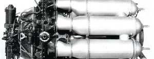
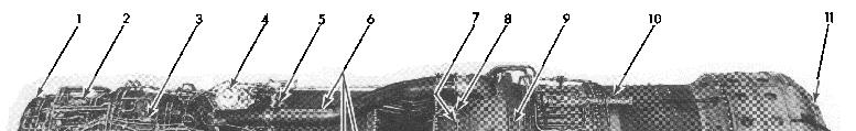
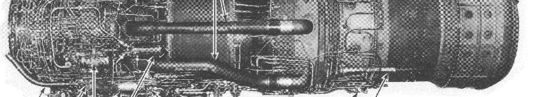
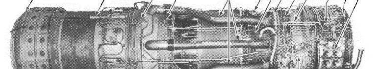
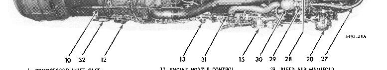
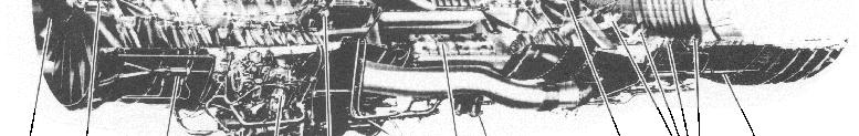
14 J58 Installation in SR-71
15 J58 ENGINE SYSTEM FUEL CONSUMPTION AT A CRUISING MACH NUMBER IS APPROXIMATELY 8,000 GALLONS PER HOUR FUEL IS JP-7, WHICH HAS AN EXTREMELY LOW VAPOR PRESSURE AND A VERY HIGH FLASH POINT TO LIGHT THIS FUEL A SPECIAL IGNITION SYSTEM IS USED. A CHEMICAL PYROPHORIC TRIETHYLBORANE (TEB), IGNITES THE MAIN ENGINE AND THE AFTERBURNER THE ENGINE OPERATES IN THE MOST HOSTILE ENVIRONMENT ANY ENGINE HAS EVER BEEN SUBJECTED TO: AIR ENTERING THE COMBUSTOR REACHES 1400 o F TURBINE INLET TEMPERATURE IS 2000 o F TEMPERATURE IN AFTERBURNER SECTION REACHES 3200 o F GROUND STARTING REQUIRES USING TWO 300 HP BUICK WILDCAT RACING ENGINES CONNECTED TO THE J58 STARTER DRIVE AT FULL AFTERBURNER POWER THE AFTERBURNER GLOWS CHERRY RED
16
17
18
19
20
21
22

23
24
25 INLET REQUIREMENTS HIGH PRESSURE RECOVERY MINIMUM DRAG AIRFLOW CAPABILITY COMPATIBLE WITH ENGINE AIRFLOW REQUIREMENTS DUCT EXIT AIRFLOW DISTORTION ACCEPTABLE TO ENGINE AIRFLOW SUPPLY TO COOL ENGINE & OPERATE EJECTOR NOZZLE STABLE OPERATION
26 SR-71 AIR INLET DESIGN DRIVERS FUNCTIONAL REQUIREMENTS FOR THE ENGINE INLET MATCH THE AIR FLOW CAPTURED BY THE INLET TO THE AIR FLOW REQUIRED BY THE ENGINE FOR ALL CONDITIONS AT SUPERSONIC CRUISE, REDUCE THE VELOCITY OF THE CAPTURED AIR TO ABOUT 0.4 MACH REQUIRED AT THE ENGINE FACE MAXIMIZE THE PRESSURE RECOVERY AT THE ENGINE FACE WHILE REDUCING VELOCITY MINIMIZE THE TRANSIENT FLOW EFFECTS OF EXTERNAL DISTRUBANCES NO FIXED INLET CONFIGURATION CAN SIMULTANEOUSLY SATISFY THESE REQUIREMENTS OVER THE ENTIRE FLIGHT ENVELOPE AND ENGINE OPERATING RANGES VARIABLE INLET GEOMETRY IS REQUIRED
27
28 INLET BLEED and BYPASS ARRANGEMENT Spike Bleed Exit Aft-Bypass Door Assembly Shock-Trap Flow Tube Forward-Bypass Exit Forward-Bypass Door Opening Spike Support Structure Forward Bypass Door Assembly Cowl Bleed (Shock Trap) Translating Spike Spike Bleed
29 SR-71 AIR INLET CHARACTERISTICS AXI-SYMMETRIC MIXED COMPRESSION INLET CHOSEN BECAUSE LOWER WEIGHT, DRAG, AND SIGNATURE OF AXI-SYMMETRIC DESIRED RANGE AND CRUISE PERFORMANCE REQUIRED PRESSURE RECOVERIES HIGHER THAN POSSIBLE WITH AN EXTERNAL COMPRESSION INLET AT MACH 3.0+ MIXED COMPRESSION INLETS CAN ATTAIN HIGH PRESSURE RECOVERY ABOVE MACH IF NORMAL SHOCK CAN BE KEPT AT THE DESIGN LOCATION JUST DOWNSTREAM OF THE MINIMUM CROSS SECTIONAL FLOW AREA (INLET THROAT) IF NORMAL SHOCK CAN BE MAINTAINED NEAR THE DESIGN LOCATION DURING INTERNAL OR EXTERNAL FLOW PERTURBATIONS IF NORMAL SHOCK CANNOT BE MAINTAINED DOWNSTREAM OF THE THROAT ABOVE MACH 2.2 INLET IS SAID TO BE UNSTARTED NORMAL SHOCK POPS OUT AND STABILIZES FORWARD OF THE INLET LIP PRESSURE RECOVERY, AIR FLOW, AND THRUST DROP TO LOW LEVELS DRAG INCREASES SIGNIFICANTLY INLET MUST BE RESTARTED AS FAST AS POSSIBLE TO PREVENT ENGINE DAMAGE AND MINIMIZE AIRPLANE YAW TRANSIENT
30 INLET SYSTEM INLET HAS A TRANSLATING 26-DEGREE CONE WHICH ACTS AS THE INITIAL DECELERATION OR COMPRESSION SURFACE PRODUCING A SERIES OF SHOCK WAVES UP TO THE INLET THROAT THE SHOCK TRAIN ENDS WITH A FINAL TERMINAL OR NORMAL SHOCK FOLLOWED BY A SUBSONIC DIFFUSER THE PURPOSE OF THE INLET IS TO SUPPLY THE AIR REQUIRED BY THE ENGINE AT THE HIGHEST PRESSURE RECOVERY AND THE LOWEST DRAG, WITH A MINIMUM OF DISTORTION. THIS IS NOT AS SIMPLE AS IT SOUNDS! A TURBOJET ENGINE IS A CONSTANT VOLUME MACHINE. THIS MEANS THAT REGARDLESS OF FLIGHT SPEED FROM M = 0 TO CRUISE SPEED THE SPEED OR MACH NUMBER ENTERING THE ENGINE IS RELATIVELY CONSTANT, BETWEEN M = 0.3 AND 0.5
31 AIR INLET THE SR-71 ENGINE AIR INLET IS A MIXED EXTERNAL AND INTERNAL COMPRESSION, AXI-SYMMETRIC INLET, WITH GRADUAL ISENTROPIC COMPRESSION APPROACHING THE THROAT THE BOUNDARY LAYER WHICH BUILDS UP ON THE CENTERBODY IS REMOVED AHEAD OF THE TERMINAL SHOCK THROUGH A POROUS BLEED THIS BLEED PASSES OVERBOARD THROUGH LOUVERS AT THE ENDS OF THE CENTERBODY SUPPORT STRUTS FORWARD BYPASS DOORS, LOCATED CLOSE TO THE THROAT MATCH THE INLET TO THE ENGINE, BY-PASSING AIR OVERBOARD THE COWL BLEED IS A SHOCK TRAP RAM BLEED WHICH SUPPLIES AIR THROUGH TUBES ACROSS THE BY-PASS DOOR REGION INTO THE ENGINE SECONDARY PASSAGE, WHERE IT IS USED FOR COOLING, AND FED THROUGH TO THE ENGINE EJECTOR AFT BY-PASS FLOW JOINS THE COWL BLEED FLOW AND PASSES THROUGH THE ENGINE EJECTOR THIS BY-PASS WAS INSTALLED TO PROVIDE SUFFICIENT FLOW TO PERMIT ENGINE OPERATION AT IDLE DURING ACCELERATION, AFT BY-PASS IS USED TO REDUCE THE FORWARD OVERBOARD BY-PASS WITH ITS ATTENDANT DRAG
32 INLET SPIKE THE INLET SPIKES REGULATE THE AMOUNT OF AIR ENTERING THE INLET BY MOVING PROGRESSIVELY REARWARDS AS THE AIRCRAFT S SPEED INCREASES THE FULLY FORWARD POSITION WHICH THE SPIKE MAINTAINS UP TO MACH 1.4 THE SPIKE AT THE LIMIT OF ITS 26-INCH AFT TRANSLATION THE CONFIGURATION OF THE INLET AT MACH 3 AND ABOVE AT THIS POINT THE CAPTURE AREA HAS INCREASED BY 112%, WHILE THE THROAT DIAMETER AT THE POINT OF MINIMUM CROSS-SECTION SECTION FURTHER DOWN THE INTAKE HAS DECREASED BY 54% IN ORDER TO HOLD THE TRI-SONIC SHOCKWAVE IN THE CORRECT POSITION AT MACH 2.2 THE INLET PRODUCES 13% OF THE OVERALL THRUST, THE ENGINE AND EJECTOR ACCOUNTING FOR 73% AND 14% RESPECTIVELY THE CORRESPONDING FIGURES AT MAXIMUM CRUISING SPEED, MACH 3+ ARE 54%, 17%, AND 29% MOST OF THE THRUST IS DEVELOPED BY THE INLET SPIKE
33 THRUST PRODUCTION
34 SR-71 INLET/EXHAUST AIRFLOW PATTERNS
35 Shock Trap Bleed Supplies Engine Cooling Air SR-71 INLET/EXHAUST AIRFLOW PATTERNS Centerbody Bleed Overboard Suck-In Doors Closed Spike Forward Shock Trap Bleed Supplies Engine Cooling Air Aft Bypass Tertiary Doors Open Fwd Bypass Doors Open Doors Closed Ejector Flaps Closed As Required to Position Inlet Shock Centerbody Bleed Overboard Suck-In Doors Closed Spike Retracting Shock Trap Bleed Supplies Engine Cooling Air Aft Bypass Doors Position B Tertiary Doors Closed Fwd Bypass Doors Open Ejector Flaps Opening As Required to Position Inlet Shock Centerbody Bleed Overboard Suck-In Doors Closed Spike Retracted FWD Bypass Doors Closed Fwd Bypass Doors Closed Aft Bypass Doors Closed Will Open as Required to Position Inlet Shock Tertiary Doors Closed Ejector Flaps Open
36 CENTERBODY BLEED ARRANGEMENT Support Strut Spike Bleed Exit Louvers (4 Locations) Spike Bleed Exit Louver View Looking AFT Support Strut Spike Bleed (Slotted Surface) Engine Face Side View
37 FORWARD BYPASS Shock Trap Tubes Bypass Exit Louvers (6 Locations) Rotary Flush Sliding Doors Bypass Exit Louvers A Forward Bypass Flow SECTION A-A Aft Bypass Doors Engine Face A Forward Bypass Doors
38 SECONDARY FLOW SYSTEMS COWL BLEED AND AFT BYPASS Shock Trap Flow Shock Trap Tubes To Ejector Aft Bypass Flow Engine Face Shock Trap Aft Bypass Doors Side View Engine Bay
39 INLET CONFIGURATION AND CONTROL THE INLET UTILIZES DAFICS COMPUTERS FOR CONTROL OF SPIKE AND BYPASS DOORS SPIKE MOVEMENT IS CONTROLLED BY MACH NUMBER, ANGLE OF ATTACK, ANGLE OF YAW, AND LOAD FACTOR THE TERMINAL SHOCK POSITION IS CONTROLLED AND REGULATED BY FORWARD AND AFT BYPASS DOORS WHICH MATCH THE INLET AIR SWALLOWING CAPABILITY TO THE ENGINE REQUIREMENT THE COMPRESSION RATIO AT CRUISE IS 40 TO 1 AT CRUISE, EACH INLET SWALLOWS APPROXIMATELY 100,000 CUBIC FEET OF AIR PER SECOND EQUIVALENT TO TWO MILLION PEOPLE BREATHING ON THE GROUND INLETS CANTED INBOARD 3.2 O EFFECT OF CHINE and FUSELAGE INLETS CANTED DOWN 5.6 O EFFECT OF ANGLE OF ATTACK AT CRUISE
40 SR-71 AIR INLET CONTROL SYSTEM FUNCTIONS FORWARD BYPASS DOORS ARE OPEN WITH THE GEAR DOWN, CLOSE WHEN LANDING GEAR RETRACTS, BUT BEGIN TO OPEN AGAIN AT MACH 1.4 TO DUMP EXCESS FLOW CAPTURED BY INLET SPIKE IS FULL FORWARD AT LOW MACH NUMBERS AND IS PROGRESSIVELY RETRACTED FOR MACH NUMBERS ABOVE 1.6 CONTROL SYSTEM POSITIONS SPIKE AS A FUNCTION OF MACH NUMBER WITH AOA, SLIDESLIP, AND NORMAL ACCELERATION BIAS NORMAL SHOCK MOVES DOWNSTREAM OF THE INLET THROAT (INLET STARTS) AT APROXIMATELY MACH 1.7 ABOVE MACH BYPASS DOORS MODULATE AS REQUIRED TO KEEP NORMAL SHOCK AT THE DESIGN LOCATION IF AN UNSTART OCCURS IN ONE INLET ABOVE MACH 2.3, BOTH SPIKES ARE DRIVEN TO THE FORWARD POSITION AND THE FORWARD BYPASS DOORS ARE OPENED TO OBTAIN A RESTART AND MINIMIZE YAW TRANSIENTS AFT BYPASS DOORS ARE SCHEDULED MANUALLY TO PROVIDE COOLING AIR TO ENGINE BAY AND EJECTOR
41
42 EJECTOR NOZZLE THE LAST PART OF THE PROPULSION SYSTEM IS THE EJECTOR THE EJECTOR PERFORMS THE REVERSE FUNCTION OF THE INLET IT ACCELERATES THE AIR COMING OUT OF THE TURBINE AT M = 0.4 UP TO M = 3.0+ THE EXIT VELOCITY MUST MATCH OR EXCEED THE FLIGHT SPEED, THEREFORE THE VARIABLE EXIT FLAPS. THEY STAY FULLY CLOSED UNTIL ABOUT M = 1.2, AND ARE FULLY OPEN AT ABOUT M = 2.4 PRIMARY NOZZLE IS A RING OF BLOW-IN DOORS WHICH PROVIDE TERTIARY AIR TO FILL IN THE EJECTOR AT MACH NUMBERS BELOW 1.2 TERTIARY AIR IS PROVIDED BY SUCK-IN DOORS AROUND THE NACELLE, AUGMENTED BY THE COWL (SHOCK TRAP BLEED AND AFT BY-PASS BLEED) MAIN EJECTOR IS SUPPORTED DOWNSTREAM ON STREAMLINED STRUTS AND A RING OF RENE 41 STEEL ALLOY ON WHICH ARE HINGED FREE-FLOATING TRAILING EDGE FLAPS OF HASTELLOY X
43
44 REFERENCES: 1. Connors, Jack, The Engines of Pratt & Whitney: A Technical History, AIAA (American Institute of Aeronautics and Astronautics, Inc.), Reston, VA, 2010, pp St. Peter, J., The History of Aircraft Gas Turbine Engine Development in the United States: A Tradition of Excellence, ASME, New York, 1999, pp Campbell, David H., F-12 Series Aircraft Propulsion System Performance and Development, AIAA No , Also found in AIAA Journal of Aircraft, Vol. 11, No. 11, November 1974, pp Note: This paper presents information only up to Mach 3.0 due to security restrictions at that time. 4. California Institute of Technology, Course Ae107, Case Studies in Engineering: The Lockheed SR-71 Blackbird, Spring Published by Cal Tech for course students and presenters only. 5. Anderson, J. Thomas, unpublished training course syllabus, How Supersonic Inlets Work: Details of The Geometry And Operation Of The SR-71 Mixed Compression Inlet, 2013.
SR-71 Inlet Design Issues And Solutions Dealing With Behaviorally Challenged Supersonic Flow Systems
 SR-71 Inlet Design Issues And Solutions Dealing With Behaviorally Challenged Supersonic Flow Systems 3/4/14 Tom Anderson 1 A-12, SR-71 Inlet Designers Dave Campbell SR-71 Inlet Designer Propulsion Boss
In this lecture... Prof. Bhaskar Roy, Prof. A M Pradeep, Department of Aerospace, IIT Bombay
 1 In this lecture... Intakes for powerplant Transport aircraft Military aircraft 2 Intakes Air intakes form the first component of all air breathing propulsion systems. The word Intake is normally used
ROCKS. Mechanical FRACTURING TO UNLOCK NEW OIL DESIGNING HUMAN TISSUE THE BLACKBIRD'S ENGINE DYNAMIC SYSTEMS AND CONTROL MAGAZINE
 Mechanical THE MAGAZINE OF ASME 2 35 No. Technology that moves the world FRACTURING ROCKS TO UNLOCK NEW OIL DESIGNING HUMAN TISSUE PAGE 8 THE BLACKBIRD'S ENGINE PAGE 36 DYNAMIC SYSTEMS AND CONTROL MAGAZINE
Lect-28. In this lecture...
 1 In this lecture... Lect-28 Performance of intakes Performance parameters Sources of losses Starting problem in supersonic intakes Modes of operation of an external compression intake 2 Intake performance
AE 452 Aeronautical Engineering Design II Installed Engine Performance. Prof. Dr. Serkan Özgen Dept. Aerospace Engineering March 2016
 AE 452 Aeronautical Engineering Design II Installed Engine Performance Prof. Dr. Serkan Özgen Dept. Aerospace Engineering March 2016 Propulsion 2 Propulsion F = ma = m V = ρv o S V V o ; thrust, P t =
In this lecture... Fixed and variable geometry nozzles Functions of nozzles Thrust vector control Thrust reversal Noise control
 1 In this lecture... Nozzle: Fixed and variable geometry nozzles Functions of nozzles Thrust vector control Thrust reversal Noise control 2 Exhaust nozzles Nozzles form the exhaust system of gas turbine
AE 451 Aeronautical Engineering Design I Propulsion and Fuel System Integration. Prof. Dr. Serkan Özgen Dept. Aerospace Engineering December 2017
 AE 451 Aeronautical Engineering Design I Propulsion and Fuel System Integration Prof. Dr. Serkan Özgen Dept. Aerospace Engineering December 2017 Propulsion system options 2 Propulsion system options 3
NASA centers team up to tackle sonic boom 18 March 2014, by Frank Jennings, Jr.
 NASA centers team up to tackle sonic boom 18 March 2014, by Frank Jennings, Jr. This rendering shows the Lockheed Martin future supersonic advanced concept featuring two engines under the wings and one
Prof. João Melo de Sousa Instituto Superior Técnico Aerospace & Applied Mechanics. Part B Acoustic Emissions 4 Airplane Noise Sources
 Prof. João Melo de Sousa Instituto Superior Técnico Aerospace & Applied Mechanics Part B Acoustic Emissions 4 Airplane Noise Sources The primary source of noise from an airplane is its propulsion system.
AERONAUTICAL ENGINEERING
 AERONAUTICAL ENGINEERING SHIBIN MOHAMED Asst. Professor Dept. of Mechanical Engineering Al Ameen Engineering College Al- Ameen Engg. College 1 Aerodynamics-Basics These fundamental basics first must be
Metrovick F2/4 Beryl. Turbo-Union RB199
 Turbo-Union RB199 Metrovick F2/4 Beryl Development of the F2, the first British axial flow turbo-jet, began in f 940. After initial flight trials in the tail of an Avro Lancaster, two F2s were installed
Design Rules and Issues with Respect to Rocket Based Combined Cycles
 Respect to Rocket Based Combined Cycles Tetsuo HIRAIWA hiraiwa.tetsuo@jaxa.jp ABSTRACT JAXA Kakuda space center has been studying rocket based combined cycle engine for the future space transportation
(VTOL) Propulsion Systems Design
 Propulsion Systems Design") 72-GT-73 $3.00 PER COPY $1.00 TO ASME MEMBERS The Society shall not be responsible for statements or opinions advanced in papers or in discussion at meetings of the Society or of its Divisions or Sections,
72-GT-73 $3.00 PER COPY $1.00 TO ASME MEMBERS The Society shall not be responsible for statements or opinions advanced in papers or in discussion at meetings of the Society or of its Divisions or Sections,
Welcome to Aerospace Engineering
 Welcome to Aerospace Engineering DESIGN-CENTERED INTRODUCTION TO AEROSPACE ENGINEERING Notes 5 Topics 1. Course Organization 2. Today's Dreams in Various Speed Ranges 3. Designing a Flight Vehicle: Route
Introduction to Gas Turbine Engines
 Introduction to Gas Turbine Engines Introduction Gas Turbine Engine - Configurations Gas Turbine Engine Gas Generator Compressor is driven by the turbine through an interconnecting shaft Turbine is driven
AE Aircraft Performance and Flight Mechanics
 AE 429 - Aircraft Performance and Flight Mechanics Propulsion Characteristics Types of Aircraft Propulsion Mechanics Reciprocating engine/propeller Turbojet Turbofan Turboprop Important Characteristics:
Chapter 4 Lecture 16. Engine characteristics 4. Topics. Chapter IV
 Chapter 4 Lecture 16 Engine characteristics 4 Topics 4.3.3 Characteristics of a typical turboprop engine 4.3.4 Characteristics of a typical turbofan engine 4.3.5 Characteristics of a typical turbojet engines
Chapter 4 Estimation of wing loading and thrust loading - 10 Lecture 18 Topics
 Chapter 4 Estimation of wing loading and thrust loading - 10 Lecture 18 Topics 4.15.3 Characteristics of a typical turboprop engine 4.15.4 Characteristics of a typical turbofan engine 4.15.5 Characteristics
Engine Performance Analysis
 Engine Performance Analysis Introduction The basics of engine performance analysis The parameters and tools used in engine performance analysis Introduction Parametric cycle analysis: Independently selected
ENGINE STARTING PERFORMANCE EVALUATION AT STATIC STATE CONDITIONS USING SUPERSONIC AIR INTAKE
 24 TH INTERNATIONAL CONGRESS OF THE AERONAUTICAL SCIENCES STARTING PERFORMANCE EVALUATION AT STATIC STATE CONDITIONS USING SUPERSONIC AIR INTAKE Author1* Takashi Nishikido Author2* Iwao Murata Author3**
General Dynamics F-16 Fighting Falcon
 General Dynamics F-16 Fighting Falcon http://www.globalsecurity.org/military/systems/aircraft/images/f-16c-19990601-f-0073c-007.jpg Adam Entsminger David Gallagher Will Graf AOE 4124 4/21/04 1 Outline
Future Trends in Aeropropulsion Gas Turbines
 Future Trends in Aeropropulsion Gas Turbines Cyrus B. Meher-Homji, P.E. Turbomachinery Group Bechtel Corporation ASME SW Texas Gas Turbine Technical Chapter 12-Nov-2012 Copyright 2012 : C.B. Meher-Homji
Compiled by Matt Zagoren
 The information provided in this document is to be used during simulated flight only and is not intended to be used in real life. Attention VA's - you may post this file on your site for download. Please
Aircraft Propulsion Technology
 Unit 90: Aircraft Propulsion Technology Unit code: L/601/7249 QCF level: 4 Credit value: 15 Aim This unit aims to develop learners understanding of the principles and laws of aircraft propulsion and their
TCDS NUMBER E00078NE U.S. DEPARTMENT OF TRANSPORTATION REVISION: 3 DATE: April 12, 2011
 TCDS NUMBER E00078NE U.S. DEPARTMENT OF TRANSPORTATION REVISION: 3 DATE: April 12, 2011 FEDERAL AVIATION ADMINISTRATION GENERAL ELECTRIC COMPANY MODELS: TYPE CERTIFICATE DATA SHEET E00078NE GEnx-1B54 GEnx-1B58
Flight Test Evaluation of C-130H Aircraft Performance with NP2000 Propellers
 Flight Test Evaluation of C-130H Aircraft Performance with NP2000 Propellers Lance Bays Lockheed Martin - C-130 Flight Sciences Telephone: (770) 494-8341 E-Mail: lance.bays@lmco.com Introduction Flight
PAC 750XL PAC 750XL PAC-750XL
 PAC 750XL The PAC 750XL combines a short take off and landing performance with a large load carrying capability. The PAC 750XL is a distinctive type. Its design philosophy is reflected in the aircraft's
The Sonic Cruiser A Concept Analysis
 International Symposium "Aviation Technologies of the XXI Century: New Aircraft Concepts and Flight Simulation", 7-8 May 2002 Aviation Salon ILA-2002, Berlin The Sonic Cruiser A Concept Analysis Dr. Martin
Propulsion System Modeling and Takeoff Distance Calculations for a Powered-Lift Aircraft with Circulation-Control Wing Aerodynamics
 47th AIAA Aerospace Sciences Meeting Including The New Horizons Forum and Aerospace Exposition AIAA 009-158 5-8 January 009, Orlando, Florida Propulsion System Modeling and Takeoff Distance Calculations
North American F-86F Sabre USER MANUAL. Virtavia F-86F Sabre DTG Steam Edition Manual Version 1
 North American F-86F Sabre USER MANUAL 0 Introduction The F-86 Sabre was a natural replacement for the F-80 Shooting Star. First introduced in 1949 for the United States Air Force, the F-86 featured excellent
Dean Andreadis Pratt & Whitney Space Propulsion, Hypersonics, West Palm Beach, FL,
 Dean Andreadis Pratt & Whitney Space Propulsion, Hypersonics, West Palm Beach, FL, 33410-9600 SCRAMJET ENGINES ENABLING THE SEAMLESS INTEGRATION OF AIR & SPACE OPERATIONS The desire to fly, to fly faster,
Jet Propulsion. Lecture-13. Ujjwal K Saha, Ph. D. Department of Mechanical Engineering Indian Institute of Technology Guwahati
 Lecture-13 Prepared under QIP-CD Cell Project Jet Propulsion Ujjwal K Saha, Ph. D. Department of Mechanical Engineering Indian Institute of Technology Guwahati 1 GE J79 Turbojet 2 Features Highly used
1.1 REMOTELY PILOTED AIRCRAFTS
 CHAPTER 1 1.1 REMOTELY PILOTED AIRCRAFTS Remotely Piloted aircrafts or RC Aircrafts are small model radiocontrolled airplanes that fly using electric motor, gas powered IC engines or small model jet engines.
FLIGHT AND WIND TUNNEL INVESTIGATION OF INSTALLATION EPFECTS ON UNDERWING SUPERSONIC CRUISE EXHAUST NOZZLES AT TRANSONIC SPEEDS
 FLIGHT AND WIND TUNNEL INVESTIGATION OF INSTALLATION EPFECTS ON UNDERWING SUPERSONIC CRUISE EXHAUST NOZZLES AT TRANSONIC SPEEDS Daniel C. Mikkelson and Bernard J. Blaha. Lewis Research Center National
North American XB-70A Valkyrie USER MANUAL. Virtavia XB-70A Valkyrie DTG Steam Edition Manual Version 1
 North American XB-70A Valkyrie USER MANUAL 0 Introduction A technological tour de force of epic proportions, the legend of the XB- 70 Valkyrie very nearly surpasses the performance of this extraordinary
Fokker 50 - Limitations GENERAL LIMITATIONS MASS LIMITATIONS. Page 1. Minimum crew. Maximum number of passenger seats.
 GENERAL LIMITATIONS Minimum crew Cockpit: Two pilots Maximum number of passenger seats Sixty-two (62) Maximum operating altitudes Maximum operating pressure altitude: Maximum take-off and landing pressure
Noise reduction by aircraft innovations
 Noise reduction by aircraft innovations Ulf Michel German Aerospace Center (DLR) Institute of Propulsion Technology, Engine Acoustics Department, Berlin English Translation of a presentation at the symposium
Cessna Citation Model Stats
 Cessna Citation Model Stats Cessna Citation Sovereign - Dimensions Length 63 ft 6 in (19.35 m) Height 20 ft 4 in (6.20 m) Wingspan 72 ft 4 in (22.04 m) Wing Wing Area Wing Sweep Wheelbase Tread 516 sq
AIRCRAFT DESIGN SUBSONIC JET TRANSPORT
 AIRCRAFT DESIGN SUBSONIC JET TRANSPORT Analyzed by: Jin Mok Professor: Dr. R.H. Liebeck Date: June 6, 2014 1 Abstract The purpose of this report is to design the results of a given specification and to
DEPARTMENT OF TRANSPORTATION FEDERAL AVIATION ADMINISTRATION TYPE CERTIFICATE DATA SHEET NO. 1E8
 DEPARTMENT OF TRANSPORTATION FEDERAL AVIATION ADMINISTRATION 1E8 Revision 18 PRATT & WHITNEY AIRCRAFT TURBO WASP JT3D-1 JT3D-3 JT3D-1A JT3D-3B JT3D-1-MC6 JT3D-3C JT3D-1A-MC6 JT3D-7 JT3D-1-MC7 JT3D-7A JT3D-1A-MC7
F135 Propulsion Integration Topics for Symposium on Jet Engines Haifa, Israel
 F135 Propulsion Integration Topics for Symposium on Jet Engines Haifa, Israel Tom Johnson Program Chief Engineer Operational Military Engines 25 October 2012 J6924_F135_Propulsion_2012-1 Agenda F135 Development
Boeing /-200/-200A Limitations
 Boeing 727-100/-200/-200A Limitations The information provided in this document is to be used during simulated flight only and is not intended to be used in real life. Attention VA's - you may post this
Design Rules and Issues with Respect to Rocket Based Combined Cycles
 Respect to Rocket Based Combined Cycles Tetsuo HIRAIWA hiraiwa.tetsuo@jaxa.jp ABSTRACT JAXA Kakuda space center has been studying rocket based combined cycle engine for the future space transportation
HY-V SCRAMJET INLET Christina McLane Virginia Polytechnic Institute and State University
 HY-V SCRAMJET INLET Christina McLane Virginia Polytechnic Institute and State University Abstract Hy-V is an undergraduate student-led scramjet engine test project. There are multiple teams at several
INDIAN INSTITUTE OF TECHNOLOGY KANPUR
 INDIAN INSTITUTE OF TECHNOLOGY KANPUR INDIAN INSTITUTE OF TECHNOLOGY KANPUR Removable, Low Noise, High Speed Tip Shape Tractor Configuration, Cant angle, Low Maintainence Hingelesss, Good Manoeuverability,
INDEX. Preflight Inspection Pages 2-4. Start Up.. Page 5. Take Off. Page 6. Approach to Landing. Pages 7-8. Emergency Procedures..
 INDEX Preflight Inspection Pages 2-4 Start Up.. Page 5 Take Off. Page 6 Approach to Landing. Pages 7-8 Emergency Procedures.. Page 9 Engine Failure Pages 10-13 Propeller Governor Failure Page 14 Fire.
Turbo-Rocket. A brand new class of hybrid rocket. Rene Nardi and Eduardo Mautone
 Turbo-Rocket R A brand new class of hybrid rocket Rene Nardi and Eduardo Mautone 53 rd AIAA/SAE/ASEE Joint Propulsion Conference July 10 12, 2017 - Atlanta, Georgia Rumo ao Espaço R - UFC Team 2 Background
UNITED STATES OF AMERICA CIVIL AERONAUTICS BOARD WASHINGTON, D.C.
 UNITED STATES OF AMERICA CIVIL AERONAUTICS BOARD WASHINGTON, D.C. Civil Air Regulations Amendment 4b-2 Effective: August 25, 1955 Adopted: July 20, 1955 AIRPLANE AIRWORTHINESS - TRANSPORT CATEGORIES MISCELLANEOUS
Comparative Study and Analysis of Air Ejector Flow in Convergent and Convergent Divergent Nozzle of Aircraft
 Comparative Study and Analysis of Air Ejector Flow in Convergent and Convergent Divergent Nozzle of Aircraft Milan Motta 1, E.Srikanth Reddy 2, V.Upender 3 1,2,3 Mechanical Engineering Department, JNTU,
The Airplane That Could!
 The Airplane That Could! Critical Design Review December 6 th, 2008 Haoyun Fu Suzanne Lessack Andrew McArthur Nicholas Rooney Jin Yan Yang Yang Agenda Criteria Preliminary Designs Down Selection Features
Study on Flow Fields in Variable Area Nozzles for Radial Turbines
 Vol. 4 No. 2 August 27 Study on Fields in Variable Area Nozzles for Radial Turbines TAMAKI Hideaki : Doctor of Engineering, P. E. Jp, Manager, Turbo Machinery Department, Product Development Center, Corporate
TURBOPROP ENGINE App. K AIAA AIRCRAFT ENGINE DESIGN
 CORSO DI LAUREA SPECIALISTICA IN Ingegneria Aerospaziale PROPULSIONE AEROSPAZIALE I TURBOPROP ENGINE App. K AIAA AIRCRAFT ENGINE DESIGN www.amazon.com LA DISPENSA E E DISPONIBILE SU http://www.ingindustriale.unisalento.it/didattica/
FRCSE powers up some of Navy s mightiest engines
 Machinist Ed Harper sets up a Reform High Speed Blade Tip Grinder to grind high-pressure compressor rotor blades from a TF34-GE-100 turbofan engine in the Crinkley Engine Facility at Fleet Readiness Center
Aeroplane Aerodynamics and Flight Controls 1 2
 11.1 Theory of Flight 11.1.1. Aeroplane Aerodynamics and Flight Controls 1 2 Operation and effect of: roll control: ailerons and spoilers, pitch control: elevators, stabilators, variable incidence stabilisers
Reducing Landing Distance
 Reducing Landing Distance I've been wondering about thrust reversers, how many kinds are there and which are the most effective? I am having a debate as to whether airplane engines reverse, or does something
An Innovative Two Stage-to-Orbit Launch Vehicle Concept
 An Innovative Two Stage-to-Orbit Launch Vehicle Concept Ramon L. Chase ANSER L. E. McKinney McKinney Associates H. D. Froning, Jr. Flight Unlimited NASA JPL/MSFC/UAH Twelfth Annual Advance Space Propulsion
AE 451 Aeronautical Engineering Design Final Examination. Instructor: Prof. Dr. Serkan ÖZGEN Date:
 Instructor: Prof. Dr. Serkan ÖZGEN Date: 11.01.2012 1. a) (8 pts) In what aspects an instantaneous turn performance is different from sustained turn? b) (8 pts) A low wing loading will always increase
ia 451s, 10-y (12) Patent Application Publication (10) Pub. No.: US 2003/ A1 (19) United States Johnson et al. (43) Pub. Date: Feb.
 Patent Application Publication (10) Pub. No.: US 2003/ A1 (19) United States Johnson et al. (43) Pub. Date: Feb.") (19) United States US 2003OO29160A1 (12) Patent Application Publication (10) Pub. No.: US 2003/0029160 A1 Johnson et al. (43) Pub. Date: Feb. 13, 2003 (54) COMBINED CYCLE PULSE DETONATION TURBINE ENGINE
(19) United States US 2003OO29160A1 (12) Patent Application Publication (10) Pub. No.: US 2003/0029160 A1 Johnson et al. (43) Pub. Date: Feb. 13, 2003 (54) COMBINED CYCLE PULSE DETONATION TURBINE ENGINE
TYPE CERTIFICATE DATA SHEET
 TYPE CERTIFICATE DATA SHEET No. IM.E.096 for PW800 Series Engines Type Certificate Holder 1000 Marie Victorin Longueuil, Quebec J4G1A1 Canada For : TE.CERT.00052 001 European Aviation Safety Agency, 2016.
AIR TRACTOR, INC. OLNEY, TEXAS
 TABLE OF CONTENTS LOG OF REVISIONS... 2 DESCRIPTION... 4 SECTION 1 LIMITATIONS... 5 SECTION 2 NORMAL PROCEDURES... 8 SECTION 3 EMERGENCY PROCEDURES... 8 SECTION 4 MANUFACTURER'S SECTION - PERFORMANCE...
FLUIDIC THRUST VECTORING NOZZLES
 FLUIDIC THRUST VECTORING NOZZLES J.J. Isaac and C. Rajashekar Propulsion Division National Aerospace Laboratories (Council of Scientific & Industrial Research) Bangalore 560017, India April 2014 SUMMARY
Hydraulic System (i.e. Brakes & Cowl Flaps)
") Hydraulic System (i.e. Brakes & Cowl Flaps) B-17 Technical Session for Flight Engineers 7/8/2017 (with post meeting revisions 7/9/2017) The B-17G (specifically our Texas Raiders, TR) has a hydraulic system
Hydraulic System (i.e. Brakes & Cowl Flaps) B-17 Technical Session for Flight Engineers 7/8/2017 (with post meeting revisions 7/9/2017) The B-17G (specifically our Texas Raiders, TR) has a hydraulic system
Revisiting the Calculations of the Aerodynamic Lift Generated over the Fuselage of the Lockheed Constellation
 Eleventh LACCEI Latin American and Caribbean Conference for Engineering and Technology (LACCEI 2013) International Competition of Student Posters and Paper, August 14-16, 2013 Cancun, Mexico. Revisiting
AN ADVANCED COUNTER-ROTATING DISK WING AIRCRAFT CONCEPT Program Update. Presented to NIAC By Carl Grant November 9th, 1999
 AN ADVANCED COUNTER-ROTATING DISK WING AIRCRAFT CONCEPT Program Update Presented to NIAC By Carl Grant November 9th, 1999 DIVERSITECH, INC. Phone: (513) 772-4447 Fax: (513) 772-4476 email: carl.grant@diversitechinc.com
B737 Performance. Takeoff & Landing. Last Rev: 02/06/2004
 B737 Performance Takeoff & Landing Last Rev: 02/06/2004 Takeoff Performance Takeoff Performance Basics Definitions: Runway Takeoff Distances Definitions: Takeoff Speeds JAR 25 Requirements Engine failure
DEPARTMENT OF TRANSPORTATION FEDERAL AVIATION ADMINISTRATION TYPE CERTIFICATE DATA SHEET NO. A33EU
 DEPARTMENT OF TRANSPORTATION FEDERAL AVIATION ADMINISTRATION A33EU Revision 2 DASSAULT-BREGUET Falcon 10 September 3, 1987 TYPE CERTIFICATE DATA SHEET NO. A33EU This data sheet which is a part of Type
Aircraft Design: A Systems Engineering Approach, M. Sadraey, Wiley, 2012 Chapter 11 Aircraft Weight Distribution Tables
 Aircraft Design: A Systems Engineering Approach, M. Sadraey, Wiley, 01 Chapter 11 Aircraft Weight Distribution Tables No Component group Elements Weight X cg Y cg Z cg 1 Wing 1.1. Wing main structure 1..
COPYRIGHTED MATERIAL. Introduction. 1.1 Gas Turbine Concepts
 1 Introduction The modern gas turbine engine used for aircraft propulsion is a complex machine comprising many systems and subsystems that are required to operate together as a complex integrated entity.
CFM REGULATION THE POWER OF FLIGHT
 CFM56-3 3 REGULATION 1 CFM56-3 2 Speed Governing System Fuel Limiting System VBV VSV N1 Vs P Idling System HPTCCV N1 Vs Z N1 Vs T Main Tasks Additional Tasks Corrections MEC PMC CFM 56-3 ENGINE OPERATIONAL
DEPARTMENT OF TRANSPORTATION FEDERAL AVIATION ADMINISTRATION. TYPE CERTIFICATE DATA SHEET No. A50NM
 DEPARTMENT OF TRANSPORTATION FEDERAL AVIATION ADMINISTRATION A50NM Dassault Aviation Falcon 2000 December 19, 1995 TYPE CERTIFICATE DATA SHEET No. A50NM This data sheet which is part of Type Certificate
European Aviation Safety Agency
 European Aviation Safety Agency EASA TYPE CERTIFICATE DATA SHEET Number: IM.E.021 Issue: 05 Date: 03 January 2013 Type: General Electric Company CF34-10E Series Engines Variants CF34-10E2A1 CF34-10E5 CF34-10E5A1
F-5E Tiger II USER MANUAL. Virtavia F-5E Tiger II DTG Steam Edition Manual Version 2.0
 F-5E Tiger II USER MANUAL 0 Introduction The F-5E Tiger II is an improved version of the original F-5 Freedom Fighter that entered service with the US Military in the early 1960s. It is a lightweight,
Sept. 10, 1963 R. L. LEUTZINGER 3,103,325
 Sept. 10, 1963 R. L. LEUTZINGER RADIAL, JET ENGINE Filled June 13, 1960 2 Sheets-Sheet l 1 E. D C N B A S. & I R A Sept. 10, 1963 Fied June 13, 1960 R. L. EUTZINGER RADAL, JET ENGINE 2 Sheets-Sheet 2 United
Chapter 3: Aircraft Construction
 Chapter 3: Aircraft Construction p. 1-3 1. Aircraft Design, Certification, and Airworthiness 1.1. Replace the letters A, B, C, and D by the appropriate name of aircraft component A: B: C: D: E: 1.2. What
Boeing B-47 Stratojet USER MANUAL. Virtavia B-47E Stratojet DTG Steam Edition Manual Version 2
 Boeing B-47 Stratojet USER MANUAL 0 Introduction The Boeing B-47 was the first swept-wing multi-engine bomber in service with the USAF. It was truly a quantum leap in aviation history, and is the forerunner
Introduction to Aerospace Engineering
 Introduction to Aerospace Engineering Lecture slides Challenge the future 1 18-9-2011 Introduction to Aerospace Engineering AE1101ab - Propulsion Delft University of Technology Prof.dr.ir. Challenge JaccotheHoekstra
OUTLINE. Commercial Requirements Insurance Mins Basic Info Systems Limitations Performance Charts Questions
 T-34B GROUND SCHOOL OUTLINE Commercial Requirements Insurance Mins Basic Info Systems Limitations Performance Charts Questions COMMERCIAL REQUIREMENTS 61.129 Aeronautical experience. (a) For an airplane
L 298/70 Official Journal of the European Union
 L 298/70 Official Journal of the European Union 16.11.2011 MODULE 12. HELICOPTER AERODYNAMICS, STRUCTURES AND SYSTEMS 12.1 Theory of Flight Rotary Wing Aerodynamics 1 2 Terminology; Effects of gyroscopic
AIAA Undergraduate Team Aircraft Design
 Homeland Defense Interceptor (HDI) 2005 2006 AIAA Undergraduate Team Aircraft Design Group Members and Responsibilities Name Discipline AIAA Number John Borgie Configuration and Systems 268357 Ron Cook
Introduction to Aerospace Propulsion
 Introduction to Aerospace Propulsion Introduction Newton s 3 rd Law of Motion as the cornerstone of propulsion Different types of aerospace propulsion systems Development of jet engines Newton s Third
Canadair Regional Jet 100/200 - Auxiliary Power Unit
 1. INTRODUCTION The auxiliary power unit (APU) is installed within a fireproof titanium enclosure in the aft equipment compartment. The APU is a fully automated gas turbine power plant which drives an
Lockheed SR-71B ( / NASA 831) Flight Log
 Flight Log") NASA Dryden Flight Research Center History Office Lockheed SR-71B (61-7956 / NASA 831) Flight Log Compiled by Peter W. Merlin September 2002 NASA crews flew four Lockheed SR-71 airplanes between July 1991
NASA Dryden Flight Research Center History Office Lockheed SR-71B (61-7956 / NASA 831) Flight Log Compiled by Peter W. Merlin September 2002 NASA crews flew four Lockheed SR-71 airplanes between July 1991
Plasma Assisted Combustion in Complex Flow Environments
 High Fidelity Modeling and Simulation of Plasma Assisted Combustion in Complex Flow Environments Vigor Yang Daniel Guggenheim School of Aerospace Engineering Georgia Institute of Technology Atlanta, Georgia
Part 1 Aerodynamic Theory COPYRIGHTED MATERIAL
 Part 1 Aerodynamic Theory COPYRIGHTED MATERIAL 5 6 1 Preliminaries Before studying the chapters dealing with the aerodynamics of each phase of flight, it is essential to understand various definitions
SILENT SUPERSONIC TECHNOLOGY DEMONSTRATION PROGRAM
 25 TH INTERNATIONAL CONGRESS OF THE AERONAUTICAL SCIENCES SILENT SUPERSONIC TECHNOLOGY DEMONSTRATION PROGRAM Akira Murakami* *Japan Aerospace Exploration Agency Keywords: Supersonic, Flight experiment,
DASSAULT AVIATION Proprietary Data
 FALCON 7X 02-70-05 CODDE 1 PAGE 1 / 6 GENERAL ACRONYMS LIST ACOC AGB APU A/T ATSV BOV CAS CB CL CMC CR DC DCU ECS EEC FADEC FBW FCU FF FOHE FSOV HP HPC HPT IGV ITT LP LPC LPT LRU MV N1 N2 PDU PLA PMA PMU
AIRCRAFT GENERAL KNOWLEDGE (1) AIRFRAME/SYSTEMS/POWERPLANT
 AIRFRAME/SYSTEMS/POWERPLANT") 1 In flight, a cantilever wing of an airplane containing fuel undergoes vertical loads which produce a bending moment: A highest at the wing root B equal to the zero -fuel weight multiplied by the span
1 In flight, a cantilever wing of an airplane containing fuel undergoes vertical loads which produce a bending moment: A highest at the wing root B equal to the zero -fuel weight multiplied by the span
Wichita State University Libraries Department of Special Collections UNIVERSITY ARCHIVES University of Wichita Engineering Reports (UWER)
") Wichita State University Libraries Department of Special Collections UNIVERSITY ARCHIVES 06-12-00-05 University of Wichita Engineering Reports (UWER) Box 1 Index 0-3 List of Publications 005 Turning Radius
Wichita State University Libraries Department of Special Collections UNIVERSITY ARCHIVES 06-12-00-05 University of Wichita Engineering Reports (UWER) Box 1 Index 0-3 List of Publications 005 Turning Radius
The Flamingo. Produced by the Metal Aircraft Corporation. Cincinnati, Ohio. Lunken Airfield. by Peter Bruemmer
 The Flamingo Produced by the Metal Aircraft Corporation Cincinnati, Ohio Lunken Airfield by Peter Bruemmer The prototype Flamingo was a Thomas E Halpin development that was designed and engineered by Ralph
Mathematics of Flight. Distance, Rate and Time
 Mathematics of Flight Distance, Rate and Time In flight applications, distance is usually measured in miles. Rate or speed is usually measured in knots (nautical miles per hour.) Time is usually measured
CHAPTER 1 AIRCRAFT GENERAL
 CHAPTER 1 AIRCRAFT GENERAL INTRODUCTION This manual provides a description of the major airframe and engine systems in the Cessna Citation Mustang (Figure 1-1). This material does not supersede, nor is
A-11 AIR FORCE APRIL, Born in the Skonk Works, Reared in Secret, It Blazes New Heights in Aircraft Performance. By J. S. Butz, Jr.
 AIR FORCE APRIL, 1964 The official pictures and statements tell very little about the A- 11. But the technical literature from open sources, when carefully interpreted, tells a good deal about what it
Facts, Fun and Fallacies about Fin-less Model Rocket Design
 Facts, Fun and Fallacies about Fin-less Model Rocket Design Introduction Fin-less model rocket design has long been a subject of debate among rocketeers wishing to build and fly true scale models of space
LAD Inc. Beechcraft King Air 200 Series Technical Ground School Syllabus Material Covered
 Topic Introduction Description Structures ATA 05 Technical Publications ATA 05 Aircraft Handling ATA 12 LAD Inc. Beechcraft King Air 200 Series Technical Ground School Syllabus Material Covered Course
AIRCRAFT AND TECHNOLOGY CONCEPTS FOR AN N+3 SUBSONIC TRANSPORT. Elena de la Rosa Blanco May 27, 2010
 AIRCRAFT AND TECHNOLOGY CONCEPTS FOR AN N+3 SUBSONIC TRANSPORT MIT, Aurora Flights Science, and Pratt & Whitney Elena de la Rosa Blanco May 27, 2010 1 The information in this document should not be disclosed
Initial / Recurrent Ground Take-Home Self-Test: The Beechcraft 58 Baron Systems, Components and Procedures
 Initial / Recurrent Ground Take-Home Self-Test: The Beechcraft 58 Baron Systems, Components and Procedures Flight Express, Inc. This take-home self-test partially satisfies the recurrent ground training
Supersonic Combustion Experimental Investigation at T2 Hypersonic Shock Tunnel
 Supersonic Combustion Experimental Investigation at T2 Hypersonic Shock Tunnel D. Romanelli Pinto, T.V.C. Marcos, R.L.M. Alcaide, A.C. Oliveira, J.B. Chanes Jr., P.G.P. Toro, and M.A.S. Minucci 1 Introduction
Introduction. Fuselage/Cockpit
 Introduction The Moravan Zlin 242L is a fully aerobatic 2 seat aircraft designed to perform all advanced flight maneuvers within an envelope of -3.5 to +6 Gs. Many military and civilian flight-training
DESIGN OF A FIFTH GENERATION AIR SUPERIORITY FIGHTER AIRCRAFT
 Proceedings of the International Conference on Mechanical Engineering and Renewable Energy 2015 (ICMERE2015) 26 29 November, 2015, Chittagong, Bangladesh ICMERE2015PI152 DESIGN OF A FIFTH GENERATION AIR
Official Journal of the European Union L 298/53
 16.11.2011 Official Journal of the European Union L 298/53 A B1 B2 B3 10.6 Continuing airworthiness 2 2 2 2 Detailed understanding of Part-21 provisions related to continuing airworthiness. Detailed understanding