CONTENTS 1 TOLERANCES AND STANDARDS Mechanical and electrical tolerances Standards 5 2 HOW TO PICK THE RIGHT ELECTRIC MOTOR 6
|
|
|
- Neil Cain
- 6 years ago
- Views:
Transcription
1
2
3 CONTENTS 1 TOLERANCES AND STANDARDS Mechanical and electrical tolerances Standards 5 2 HOW TO PICK THE RIGHT ELECTRIC MOTOR Classify hazardous area EX markings or RAEL electric motors 13 3 GENERAL INFORMATION Motors range Main features Main options 16 4 CABLE ENTRIES, TERMINAL BOX AND WIRING DIAGRAM Cable entries and terminal box Wiring diagrams 18 5 MECHANICAL CHARACTERISTIC Mounting arrangements Main components material Radial force permissible at the shaft end 21 6 ELECTRICAL DATA General information Three phase 1 speed motors Three phase 2 speed motors constant torque Three phase 2 speed quadratic torque 31 7 OVERALL DIMENSION Three phase motors 35 8 SPARE PARTS Personnel qualification List of spare parts 36 MIA MIA 1 Eng. Ed.2013/00 3 di 40
4 1 TOLERANCES AND STANDARDS 1.1 Mechanical and electrical tolerances: Symbol Description Tolerance A Distance between centre-lines of fixing holes (end view) ± 1 mm AB Overall dimensions across the feet (end view) + 2 % AC Diameter of the motor (without terminal box) + 2 % B Distance between centre-lines of fixing holes (side view) ± 1 mm C - CA D - DA E - EA Distance from the shaft end shoulder to the centre-line of nearest mounting holes in the feet Diameter of the shaft extension. Length of the shaft extension from the shoulder ± 3 mm Ø Ø Ø 55 Ø < 55 mm Ø > 60 mm F - FA Width of the keyway of the shaft extension h9 GA - GC Distance from the top of the key to the opposite surface of the shaft extension + 0,2 mm H Distance between the centre-line of the shaft to the bottom of the feet H 250 H 280 HD Distance from the top of the terminal box and to the bottom of the feet + 2 % K Diameter of the holes or width of the slots in the feet of the motor + 3 % L Overall length of the motor with a single shaft extension + 1 % M Pitch circle diameter of the fixing holes ± 0,8 mm N Diameter of the spigot Ø < 230 j6 Ø 250 h6 P Outside diameter of the flange ± 1 mm R Distance from the shaft shoulder to the mounting surface of the flange ± 3 mm S Diameter of the fixing holes in the mounting flange or nominal diameter of thread + 3 % Distance from the shaft shoulder to the mounting surface of the flange with locked bearing ± 0,5 mm Mass of the motor Da 5 a + 10 % j6 k6 m6-0,3 mm + 0,5 mm - 0,5 mm - 1 mm Quantity Efficiency (η) Tolerance Total losses +10% Power factor (Cos ϕ) Slip (rpm) (at full load and working temperature) Locked rotor current (I A ) + 20% - 0,15 (1-η) for P N < 50 kw 1-cosϕ minimum absolute value 0,02 6 maximum absolute value 0,07 ± 30% per P N < 1 kw ± 20% per P N > 1 kw Locked rotor torque (T A ) -15% a +25% Breakdown torque (T max ) -10% ( for this tolerance the value T max / T n should be at least 1,6) Moment de Inertia (J) ±10% Sound intensity level (sound pressure) +3 db (A) MIA MIA 1 Eng. Ed.2013/00 4 di 40
5 1.2 Standards RAEL electric motors conforms to the following standards: TITLE EU CENELEC International IEC Rotating electrical machines Part 1: Rating and performance Rotating electrical machines Part 2-1:Standard methods for determining losses and efficiency from tests (excluding machines for traction vehicles) Rotating electrical machines. Part 5: Degrees of protection provided by the integral design of rotating electrical machines (IP code). Classification Rotating electrical machines Part 6: Methods of cooling (IC Code) Rotating electrical machines Part 7: Classification of types of construction, mounting arrangements and terminal box position (IM Code) Rotating electrical machines Part 9: Noise limits EN IEC EN IEC EN IEC EN IEC EN IEC EN IEC Rotating electrical machines Part 12: Starting performance of single-speed three-phase cage induction motors Rotating electrical machines Part 14: Mechanical vibration of certain machines with shaft heights 56 mm and higher - Measurement, evaluation and limits of vibration severity General purpose three-phase induction motors having standard dimensions and outputs. Frame numbers 56 to 315 and flange numbers 65 to 740 EN IEC EN IEC EN IEC Degrees of protection provided by enclosures (IP Code) EN IEC Electrical apparatus for explosive gas atmospheres Part 0: General requirements EN IEC Electrical apparatus for explosive gas atmospheres Part 1: Flameproof enclosures 'd' EN IEC Electrical apparatus for explosive gas atmospheres Part 7: Increased safety "e" EN IEC Electrical apparatus for use in the presence of combustible dust Part 0: General requirements EN IEC Electrical apparatus for use in the presence of combustible dust Part 1: Protection by enclosures "td" EN IEC MIA MIA 1 Eng. Ed.2013/00 5 di 40
6 2 HOW TO PICK THE RIGHT ELECTRIC MOTOR 2.1 Classify hazardous area The first step is determining the proper hazardous area classification. When an electric motor is to be operated in a location that contains hazardous materials, it is the responsibility of the end-user to determine the applicable class, category and group. There are a number of ways to prevent sparks, heat or short-circuits from causing ignition of the explosive atmosphere. Generally electric motors are available in the following protection types: Flameproof, Increased safety, Non-sparking, Pressurized and Dust ignition proof. ZONE & CATEGORY CLASSIFICATION GAS DUST CATEGORY PROTECTION LEVEL DESCRIPTION Very high Explosive atmospheres are present continually or for long periods or frequently High Explosive atmospheres are likely to occur under normal operations, occasionally Normal Explosive atmospheres are not expected to occur under normal operations. Where they do occur, it will be for a short period only. PROTECTION TYPE CODE SUITABLE FOR ZONES PROTECTION BY GAS DUST GAS DUST d Flameproof Enclosure 1 ta 20 tb Enclosure 21 tc 22 px pd 1 21/22 py pd Pressurized Enclosure 1 21/22 pz pd 2 21/22 q Powder filling 1 o Oil immersion 1 e Increased safety 1 ia ia 0 20 ib ib Intrinsic safety 1 21 Ic ic 2 22 na Non sparking 2 nr Restricted breathing enclosures 2 nl Limited energy 2 nc Enclosed break 2 ma ma 0 20 mb mb Encapsulation 1 21 mc mc 2 22 RAEL MIA and MIA1 motors are available in the underscored protection type MIA MIA 1 Eng. Ed.2013/00 6 di 40
7 ATMOSPHERE An explosive atmosphere can be one in the form of gases, vapours, mists or dusts, which can ignite under certain operating conditions. For ATEX purposes, atmosphere comes in two classifications: G for explosive gas and D for combustible dust. A product certified for both gas and dust is marked G and D ZONES The division of a hazardous area into zones depending on the frequency with which explosive atmosphere occurs. ATEX divides hazardous environment into zones and states which category of equipment that can be used in each zone. Atmospheres are classified into zones. Zones 0, 1 and 2 refer to gas, while Zones 20, 21 and 22 refer to dust. GROUP Under the ATEX Directive, equipment is designated by the type of potentially explosive atmosphere in which the equipment may be used : -Group 1 (I) The underground parts of mines, and to those parts of surface installations of mines, that are liable to be endangered by firedamp (methane) and/or combustible dust. -Group 2 (II) for surface industries. CATEGORY Hazardous area equipment is arranged in categories depending on its degree of protection, indicating where the item can be used: -Category 1 Equipment designed for very high level of safety. Requires two independent means of protection or safe operation with two separate faults. Used where explosive atmospheres are present continuously or for lengthy periods, typically Zone 0 and Zone 20. -Category 2 Equipment designed for a high level of safety. Requires the design to be safe with frequently occurring disturbances or with one operating fault. Used where explosive atmospheres are likely to occur, typically Zone 1 and Zone 21. -Category 3 Equipment designed for a normal level of safety. Used where explosive atmospheres are likely to occur infrequently and to be of short duration, typically Zone 2 and Zone 22. CLASSIFICATION OF GAS GROUP ATEX defines four groups of gases, based on how easily-ignitable they are (by a flame or spark; not via self-ignition). Group I (mining) there is only one gas group, namely methane. Group II is subdivided into IIA, IIB, IIC. Electrical apparatus certified for IIB may be used in applications requiring apparatus to be certified for group IIA. Electrical apparatus certified for IIC may be used in applications requiring apparatus to becertified for groups IIA and IIB. GAS GROUP COMMON GASES I (Mining) Methane IIA Propane, ethanol, ammonia, butane.. IIB Ethylene, hydrogen sulphide.. IIC Hydrogen, Acetylene.. The table at page 11 indicates the groups to which some gas mixtures belong MIA MIA 1 Eng. Ed.2013/00 7 di 40
8 CLASSIFICATION OF DUSTS With ATEX, combustible dust is for the first time included in the regulations governing hazardous atmospheres. Typical applications include handling of grain, coal, sugar, wood and some chemical substances such as sulphur. IEC :2007 defines the new atmosphere group III for explosive dusts in surface industries (i.e. ATEX group II). There are three dust groups in the standard, defined by the properties of the dust: DUST GROUP TYPE CHARACTERISTICS IIIA Combustible flyings Finely divided solid particles, 500 µm or less in nominal size, which may be suspended in air, may settle out of the atmosphere under their own weight, may burn or glow in air, and may form explosive mixtures with air at atmospheric pressure and normal temperatures. IIIB Non-conductive dust Combustible dust with electrical resistivity greater than 10 3 Ω.m IIIC Conductive dust Combustible dust with electrical resistivity equal to or less than 10 3 Ω.m The self-ignition temperature of a dust suspended in the air is usually higher than the same dust accumulated on a surface. When selecting equipment for use in dusty environments, the surface temperature of the equipment should not exceed 2/3 of the suspended self-ignition temperature, and should be at least 75 C below the self-ignition temperature of a 5mm accumulated layer of the dust. For example, cotton has self-ignition temperatures of 560 C (suspended) and 350 C (accumulated). Your equipment s maximum surface temperature must be less than 373 C (suspended) and 275 C (accumulated), so the limit is 275 C. Equipment classified T3 (200 C) is acceptable, but T2 (300 C) is not. Table at page 12 indicates a list of main substance and raw material and their ignition property TEMPERATURE CLASS Rather than mark equipment with an actual temperature to show how hot it gets in operation, a temperature class is used. The T-class is based on the hottest surface where igniting the flammable gas would destroy the protection. Generally, T-class is based on fault conditions or, at the very least, worst case normal operating conditions. When selecting equipment, the T-class must be below the auto-ignition temperature of the gas. For dust explosion proof, the max surface temperature is directly shown (e.g.t80 C) TEMPERATURE CLASS MAXIMUM SURFACE TEMP (C ) IGNITION TEMPERATURE T1 450 >450 T2 300 >300 T3 200 >200 T4 135 >135 T5 100 >100 T6 85 >85 AMBIENT TEMPERATURE The T class indicates the maximum temperature of surfaces which could ignite an external explosive atmosphere. Unless indicated, the ambient temperature range for which the equipment is intended is -20 C to + 40 C. If the T amb range is other than standard, the T-Class will be followed by the applicable ambient for example: T4 (65C Amb) (would mean that the equipment would not exceed its T4 rating (135C) EVEN IF the ambient temperature gets as hot as 65 C) MIA MIA 1 Eng. Ed.2013/00 8 di 40
9 IP PROTECTION RATING The Ingress Protection rating defined in IEC/EN is a measure of the resistance of an enclosure to penetration by dust or liquid, and is not specifically an Ex concept. Several of the EN/IEC standards do require the IP rating to be shown as part of the Explosion Classification, but having an IP rating in and of itself is not proof the equipment is safe to use in an explosive atmosphere. Note that the IP rating system considers ingress which is harmful, so an IPx8 product may still show some ingress of water when submersed, but not enough to cause any malfunction. Solid particle protection: The first digit indicates the level of protection that the enclosure provides against access to hazardous parts (e.g., electrical conductors, moving parts) and the ingress of solid foreign objects. Liquid ingress protection: The second digit indicates the level of protection that the enclosure provides against harmful ingress of water FIRST NUMBER SECOND NUMBER IP PROTECTION PROVIDED IP PROTECTION PROVIDED 0 No Protection 0 No Protection 1 Protection against solid objects - 50mm 1 Protection against vertical drops of water (showerproof) 2 Protection against solid objects - 12mm 2 Protection of up to 15 deg vertical direct sprays of water (rainproof) 3 Protection against solid objects - 2.5mm 3 Protection of up to 60 deg vertical direct sprays of water 4 Protection against solid objects - 1mm 4 Protection from water sprayed in all directions 5 Limited Protection against dust 5 Protection from low pressure jets of water in all directions 6 Complete protection against dust 6 Protection from strong jets of water 7 Protection from temporary immersion of up to 1m for 30 mins 8 Protection from Complete immersion for specified depth and unlimited time EQUIPMENT PROTECTION LEVEL (EPL) IEC standards now include provision for equipment on the basis of risk. If the consequences of an explosion are deemed particularly severe, then to decrease the risk, the category/zone relationship can be changed to give a lower possibility of ignition. So category 2 apparatus could be selected for use in a zone 2 for instance: GROUP Group I Group II Group III EPL Ma Mb Ga Gb Gc Da Db Dc INTENDED FOR EQUIPMENT GROUP Equipment for mining Equipment for explosive gas atmospheres Equipment for explosive dust atmospheres GIVING PROTECTION High level of protection against becoming an ignition source Level of protection which can be electrically isolated if hazardous atmosphere is known to exist Very High level of protection against becoming an ignition source High level of protection against becoming an ignition source Assured level of protection against becoming an ignition source in normal operation Very High level of protection against becoming an ignition source High level of protection against becoming an ignition source Assured level of protection against becoming an ignition source in normal operation MIA MIA 1 Eng. Ed.2013/00 9 di 40
10 RAEL motors series MIA and MIA1 have the following types of protection: -Ex e IIC Increased safety (GAS) or Ex tb IIIC enclosures (DUST) or both markings -Ex na IIC Non-sparking (GAS) or Ex tc IIIC enclosures (DUST) or both markings Increased safety Ex e (MIA Series motor) The motor with increased safety prevents sparking, arcing and hot spots during the service (including start conditions at locked rotor), which could lead to ignition of a potential explosive atmosphere that surrounds both the internal and external parts of the engine. This is ensured under certain constructional and dimensional information concerning: -Minimum distances through air and between the surfaces -Use of high resistance trace-proof insulating materials -Elimination of sharp edges that may accumulate static electricity and verification of a correct coupling between electrical and mechanical parts. -minimum distance between the fixed and rotating parts (eg. between iron rotor / stator) -limits of temperature rise, considering the locked rotor situation and normal operation in the most unfavorable thermal condition (power supply voltage to the lower or upper tolerance limit). Thermal protection a) When the protection against over temperatures is realized via amperometric device, it will be listed on the plate the ratio between the currents I A / I N and the time t E (t E must not be less than 5 sec while I A / I N should not be than 10) b) When the protection against over temperatures is achieved via thermal protectors, placed inside the windings and connected to a release device, will be reported in the plate only current ratio I A / I N. The time t E should not be shown on the nameplate O= temperature at 0 C A= maximum ambient temperature B= temperature at rated load and worst voltage conditions C= max. temperature allowed by the insulation class D= max limit of temperature(gas temperature class) E= Temperature rise curve at rated output and at worst voltage conditions F= Temperature rise with locked rotor (t E ) Ex na protection (MIA1 Series motor) This type of protection is allowed in hazardous areas classified as Zone 2, which require a normal protection. These constructions are known as non-sparking and the motor must be designed so that no spark is formed in the normal operating conditions. For the determination of the maximum allowable temperature are therefore excluding startup situations with locked rotor Protection through enclosures Ex tb (MIA) ed Ex tc (MIA1) This type of protection prevents each transmission of explosive powders because the degree of IP protection prevents the dust from entering inside the motor, the maximum surface temperature of the motor does not exceed the temperature limit and no spark can escape from the housing of the motor. MIA MIA 1 Eng. Ed.2013/00 10 di 40
11 Main inflammable gases, group and temperature class belonging (IIA, IIB, IIC) and temperature of ignition. Inflammable substance Group of GAS temperature of ignition Class of Temperature ( C) Inflammable substance Group of GAS temperature of ignition Class of Temperature ( C) 2-Methylpentane IIA 300 T2 Ethyl formate IIA 440 T2 Amyl acetate IIA 360 T2 Methyl formate IIA 450 T1 Butyl-n acetate IIA 425 T2 Natural gas IIA 482 T1 Ethyl acetate IIA 426 T2 Isobutane IIA 460 T1 Isobutil acetate IIA 420 T2 Isoheptane IIA 220 T3 Methyl acetate IIA 502 T1 Isohexane IIA 264 T3 Propil acetate IIA 430 T2 Isooctane IIA 410 T2 Vinyl acetate IIA 425 T2 Isoprene IIA 220 T3 Acetone IIA 465 T1 Methane IIA 537 T1 Methanol IIA 464 T1 Methylcyclopentane IIA 258 T3 Bromethane IIA 511 T1 Methylamine IIA 430 T2 Butane IIA 287 T3 Methylmetacrylate IIA 430 T2 Butene - 1 IIA 384 T2 Paraldehyde IIA 239 T3 Butene - 2 IIA 325 T2 Pentane IIA 258 T3 Cycloexano IIA 259 T3 Pyridine IIA 483 T1 Cycloexanol IIA 300 T2 Propane IIA 470 T1 Cyclohexanone IIA 419 T2 Propylamine IIA 318 T2 Cyclohexene IIA 244 T3 Propylbenzene IIA 450 T1 Cyclopropane IIA 498 T1 Propylene IIA 455 T1 Cymene (p) IIA 436 T2 Styrene IIA 490 T1 Chloro-benzene IIA 637 T1 Toluene IIA 480 T1 Acetyl chloride IIA 390 T2 m-xylene IIA 522 T1 Allyl chloride IIA 390 T2 o-xylene IIA 464 T1 Chlorbutane IIA 240 T3 p-xilene IIA 528 T1 Chloroethane IIA 495 T1 1,2 Butadiene IIB 430 T2 Vinyl chloride IIA 472 T1 1,3 Butadiene IIB 430 T2 Dichlorobenzene IIA 648 T1 Dioxane IIB 245 T3 Dichloroethylene 1,1 IIA 570 T1 Diethyl ether IIB 160 T4 Dichloroethylene 1,2 IIA 441 T2 Ethyl vinyl ether IIB 200 T3 Diethylamine IIA 312 T2 Methyl vinyl ether IIB 350 T2 Dimethylamine IIA 400 T2 Acrylate ethyl IIB 350 T2 Dimethylaniline IIA 371 T2 Ethylene IIB 425 T2 Dimethylbutane 2,3 IIA 405 T2 LPG IIB 365 T2 Dimethylpentane 2,3 IIA 330 T2 Sulphurated Hydrogen IIB 260 T3 Heptane IIA 215 T3 Methylacrylate IIB 415 T2 Hexane IIA 233 T3 Carbon monoxide IIB 605 T1 Heptane IIA 515 T1 Ethylene oxide IIB 435 T2 Ethylacetoacetate IIA 350 T2 Propylene oxide IIB 430 T2 Ethylamine IIA 385 T2 Acetylene IIC 305 T2 Ethylmercaptane IIA 295 T3 Hydrogen IIC 500 T1 Butyl formate IIA 320 T2 Carbon disulfide IIC 95 T6 MIA MIA 1 Eng. Ed.2013/00 11 di 40
12 Main inflammable DUSTS and their typical ignition temperature Substance Medium largeness particles (µm) LEL (g/m3) Cloud ignition temperature (C ) Layer 5mm thick ignition temperature ( C) Metals, alloys Aluminium Bronze Iron >450 Graphite Lamp-black (carbon black) Sulphur Wood, products of wood, fibres Paper Cellulose (93% sweet wood, 6% hard wood) wood flour Wood (50% pear tree and 50% kernel) Wood (beech) Wood (pear tree) Sawdust of wood Cork Agricultural products Cacao Coffee Cereals (mixed powders) Wheat flour >450 Soy flour Gelatine >450 Wheat Dry milk Milk sugar >450 Rye Buttermilk Tobacco Black tea Sugar >450 Powdered sugar >450 Marking example MIA MIA 1 Eng. Ed.2013/00 12 di 40

13 2.2 EX markings or RAEL electric motors RAEL Ex motors have been designed to be used in applications with the presence of an explosive atmosphere due both to the presence of gases that the presence of combustible dust. Motors for zone 1 and 21 (redundant for areas 2 e 22) IP 55 when there is the GAS marking DUST marking In case of a gas and dust protected motor the marking is the one on the nameplate above GAS marking Motors for zone 2 and 22 IP 55 when there is the GAS marking DUST marking In case of a gas and dust protected motor the marking is the one on the nameplate above GAS marking MIA MIA 1 Eng. Ed.2013/00 13 di 40
14 3 GENERAL INFORMATION 3.1 Motors range MIA and MIA1 series motors in this catalog are manufactured according to European standards of equipment and protective systems suitable for potentially explosive atmospheres in accordance with ATEX Directive 94/9/EC. These motors according to ATEX directives are provided: - Certificate of EC type - Notification of Quality Assurance Product These certificates are issued by notified bodies authorized to issue. Series motors MIA (MIA 1) with IP55 protection are suitable for use in area 1 and area 2, while the IP66 are also suitable for use in zone 21 and zone 22. Version Frame size (mm) Power (kw) Poles GAS group Temperat ure class motors 2G Surface temperature motors 2GD Ambient temperature Three phase 1 speed Poli ,06 18,5 2 0, , ,06-7,5 8 IIC T4 T5 T6 T 135 C T 100 C T 85 ºC -40ºC a +60ºC Three phase 2 speed Constant torque 2/4-4/8 4/6 6/8 poles ,25/0,18-15/12 2/4 0,18/0,09 10/6,6 4/8 0,2/0,1 8,8/5,9 4/6 0,08/0,12 5,5/4 6/8 IIC T4 T5 T6 T 135 C T 100 C T 85 ºC -40ºC a +60ºC 0,25/0,06 16/4,4 2/4 T4 T 135 C Three phase 2 speeds Quadratic torque 2/4-4/8 4/6 6/8 poles ,25/0,05 12/3,2 4/8 0,3/0,1 11/3,3 4/6 0,33/0,09 7,5/4 6/8 IIC T5 T6 T 100 C T 85 ºC -40ºC a +60ºC 0,06 18,5 2 Three phase for Inverter Poli , , ,06 7,5 8 0,06 1,6 4 IIC T4 T 135 C -40ºC a +60ºC 0,06 1,1 6 MIA MIA 1 Eng. Ed.2013/00 14 di 40
15 3.2 Main features Motors MIA and MIA1 are in conformity with the Essential Health and Safety Requirements for potentially explosive atmospheres provided by European Standards: EN , EN , EN , EN , EN , EN Three-phase and single-phase squirrel cage asynchronous induction motors. Aluminium modular motors, flanges and feet can be assembled and disassembled. Type of protection Ex e, (Ex tb) Ex na, (Ex tc) Overall dimensions comply with IEC Ventilations IC 411 (Self ventilated). Voltage 230/400 V ± 5% /Y (56-112), 400/690 V ± 5% /Y ( ), frequency 50 Hz ± 2%. Insulation Class F. Wiring produced using enamelled copper wires with double insulating coat, and varnished with a third layer dried in oven. Protection degree IP55 for area 1 and area 2, IP66 for area 21 and area 22. Maximum noise level 80 db (A). Fan cover in sheet metal Low friction dust seals. Motor carcass and flanges IEC compliant, made using die cast aluminum with high mechanical strength Durt cycle S1 Standard ambient temperature -40 C; +60 C MIA MIA 1 Eng. Ed.2013/00 15 di 40
16 3.3 Main options Motors 2GD protection degree IP66 suitable for zone 21 and zone 22. Special Powers on frame 132 and 160 Thermal protections (PTC or PTO probes). Heating resistors anti condensation Insulation class H. Tropicalized motors Motors suitable for inverters Special shafts Special flanges Terminal box in right and left position. Temperature class T5 and T6. Standard painting Special painting for marine environment Tests All motors RAEL are 100% tested, both at the beginning of production (test of winding) and at the end of production (electrical test). On request we can conduct specific tests: A standard Routine Test. Heating test. MIA MIA 1 Eng. Ed.2013/00 16 di 40
 is then possible to have the terminal box is at the top (A) on the right side (C)")
17 4 CABLE ENTRY, TERMINAL BOX AND WIRING DIAGRAM 4.1 Cable entries and terminal box Having the ability of mounting the feet in three different positions (size 63-71) is then possible to have the terminal box is at the top (A) on the right side (C) and on the left side (B) of the motor as shown in figure 1. The terminal box can be mounted on the motor so as to have the output cables in the four positions shown in Figure 2. Standard installation of the terminal box is in position A-4 A 2 Altezza d asse Entrata cavi Standard x M x M20-1 x M x M32 B C 4 Motors with frame size from 56 to 90 use M4 terminals, motors with frame size 100 to 112use M5 terminal, motors with frame size 132 to 160 use M6 terminals. MIA MIA 1 Eng. Ed.2013/00 17 di 40
18 4.2 WIRING DIAGRAMS Three phase 1 speed Star and delta connection Standard Star Delta Without Terminal box Star Delta Three phase 2 speed Dahlander Connection - 2/4-4/8 poles Costant Torque High speed Low speed Quadratic Torque High speed Low speed Three phase 2 speed 2 separate windings - 4/6-6/8 poles High speed Low speed MIA MIA 1 Eng. Ed.2013/00 18 di 40
19 5 MECHANICAL CHARACTERISTICS 5.1 Mounting arrangements MIA motors can be made in the mounting arrangements as shown in the table. The basic mounting arrangements are shown in the standard EN Motors with mounting arrangements IM B3, IM B5, IM B14 can also be used in different mounting positions. IM B3 IM B6, IM B7, IM B8, IM V5 o IM V6. IM B35 IM V15 o IM V36, IM 2051, IM 2061, IM IM B34 IM 2111 O IM 2131, IM 2151, IM 2161, IM IM B5 IM V1 o IM V3. (flange with passing holes). IM B14 IM V18 o IM V19. (flange with threaded holes). COMMON MOUNTINGS OTHER MOUNTINGS IM B3 IM V5 IM V6 IM B6 IM B7 IM B8 IM 1001 IM 1011 IM 1031 IM 1051 IM 1061 IM 1071 IM B35 IM V15 IM V IM 2001 IM 2011 IM 2031 IM 2051 IM 2061 IM 2071 IM B IM 2101 IM 2111 IM 2131 IM 2151 IM 2161 IM 2171 IM B5 IM V1 IM V3 IM 3001 IM 3011 IM 3031 IM B14 IM V18 IM V19 IM 3601 IM 3611 IM 3631 MIA MIA 1 Eng. Ed.2013/00 19 di 40
20 5.2 MAIN COMPONENTS MATERIAL Material type Shield fames flanges terminal box Shaft Rotor Fan Fan cover Tie rods Screw Cable glands Motor Plate Aluminium Steel 35S20 Die-cast Aluminium (squirrel cage) Thermoplastic material or Aluminium Zinc-plated steel Steel 4.8 Steel 8.8 nickelplated brass Anodized aluminium or on request stainless steel Bearings The 2Z series bearings are lubricated for life and required not further lubrication. Nevertheless, we recommend in case of continuous running, long time stop, low temperature, radial and/or axial load, frequency inverter used, to control some time to time the ball bearings ( hours for 4,6,8 pole motors and hours for the 2 pole motors). Motor Bearing Frame Poles Drive-end shield Rear shield Lubrication Z Z It doesn t need lubrication Z Z It doesn t need lubrication Z Z It doesn t need lubrication Z Z It doesn t need lubrication Z Z It doesn t need lubrication Z Z It doesn t need lubrication Z Z It doesn t need lubrication Z Z It doesn t need lubrication Z Z It doesn t need lubrication Rings for shafts MIA and MIA1motors can be equipped with seals to ensure a degree of protection IP66. In this way the motor is protected from ingress of dust and contaminants. Motor Rings Frame size Poles Front Rear v-ring Ø12 v-ring Ø v-ring Ø14 v-ring Ø v-ring Ø14 v-ring Ø v-ring Ø20 v-ring Ø v-ring Ø25 v-ring Ø v-ring Ø30 v-ring Ø v-ring Ø30 v-ring Ø v-ring Ø40 v-ring Ø v-ring Ø45 v-ring Ø45 MIA MIA 1 Eng. Ed.2013/00 20 di 40

21 5.3 RADIAL FORCE PERMISSIBLE AT THE SHAFT END The table below shows the permissible radial load (F R) position in the L / 2, assuming the engine operating at 50 Hz and a working life of the bearings of at least 20,000 hours for 2-pole motors and engines 40,000 hours for poles. For operation 60Hz these values should be reduced by 10%. For double speed motors take as a reference the highest speed Considering the load FR applied in the X position equal to L / 2 we have the load limit values shown in the table: Motor C Bearing type F Dynamic R in X=L/2 (N) load Front Rear (N) poles poles poles poles ZZ 6201-ZZ ZZ 6202-ZZ ZZ 6202-ZZ ZZ 6204-ZZ ZZ 6205-ZZ ZZ 6206-ZZ ZZ 6306-ZZ ZZ 6308-ZZ ZZ 6309-ZZ Axial forces permissible on the shaft The table below shows the maximum axial loads (F A) Permitted on the motor bearings, these values are provided from the bearing manufacturers and learned through experience. The value is about 2% of the dynamic load of the bearing indicated in the above table. Motor F A (N) For applications with pulley and belt the maximum radial load Fr is given by P = weight of the pulley [N] F = tension of the belt [N] = (2. K. M) / D where K = factor for belt tension belt (K = 3 for flat belt without belt tensioner, K = 2.2 ver V-belt, flat belt for K = 2 D = diameter of pulley [m] M = torque [Nm] = 9550 P / n where P = shaft power [kw] n = rotational speed [rpm] MIA MIA 1 Eng. Ed.2013/00 21 di 40
22 6 ELECTRICAL DATA 6.1 General information In case the motors are driven by INVERTER we have to point out some things: Motor must be equipped with PTC thermistor. Motor driven by inverter means not to have a perfect voltage and current sine wave with increase of losses and heating of the motor. Speed variation affects also the ventilation (in case of IC411). The stress on the bearings increases and they shall be checked more frequently; for this reason the operating period with a speed above 3600 rpm shall never exceed 10% of the complete working cycle. The best connection for motors driven by inverter is the star connection 400V. In case of constant torque application and with frequency values above 60Hz it is necessary to use a delta connection. For all these reasons RAEL manufactures special motors for inverter duty so to minimize all the inconveniences described above. These motors are electrically oversized so to minimize the electrical losses and also reduce the heating and are provided with thermistor PTC120 C for temperature class T4; for this reason the winding of the motor is made on a oversized stator and is fitted with phase-insulators (on request it is possible to have the version T5 with PTC90 C and T6 with PTC70 C). All the bearings mounted on RAEL motors are produced by NSK. A Servo-Ventilated (IC416) version must be certified. 6.2 Three phase 1 speed motors In this paragraph we will show the rating of the 1 speed 3-phase motors and the rating of the motors for inverter duty. The values of power and current reported in the tables relating to special motors for inverter are indicative and have meaning only in the case where the inverter used is of excellent quality and high performance. The following pages show the data for electric motors with increased safety Ex e (TUV certified IT 12ATEX 068X) The electrical data for Ex na motors (TUV EN 12 ATEX 069X) appear to be the same as shown in the following pages and referred to the increased safety Ex e motors. The features of three phase motors for general purpose are as follow: Three phase asynchronous motor, squirrel cage rotor, self ventilated (IC411). Duty S1, Insulation class "F", IP55, 400V - 50 Hz. Connections Type Y V 400V V 690 V for INVERTER 230 V 400 V MIA MIA 1 Eng. Ed.2013/00 22 di 40
23 II 2G - II 2D - Ex e 1 speed 3000 Rated data at 400V/50Hz direct on line start Tamb -40 C/+60 C Moment P In Part rpm η Cos M Type Number min -1 I n m Class of inertia Certificate a/i n M % ϕ Nm a/m n TUV IT 12 kw Hp 400 V kg T J ATEX 068X Amp kgm 2 Part number MIA 0042 MIA 56 A 2 0,06 0, ,40 3,5 67 0,77 0,2 3,5 2.6 T MIA 0043 MIA 56 A 2 0,09 0, ,46 4,0 67 0,77 0,3 4,0 2.8 T MIA 0044 MIA 56 B 2 0,12 0, ,53 3,5 70 0,77 0,35 4,0 3.2 T4 0.1 MIA 0001 MIA 63 A 2 0,12 0, , , T MIA 0002 MIA 63 A 2 0,18 0, , , T MIA 0003 MIA 63 B 2 0,25 0, , , T MIA 0004 MIA 71 A 2 0,37 0, , ,3 3,0 5.6 T MIA 0005 MIA 71 B 2 0,55 0, , ,1 3,0 6.1 T MIA 0006 MIA 80 A 2 0,75 1, ,00 5, , T MIA 0007 MIA 80 B 2 1,10 1, , ,8 3, T MIA 0008 MIA 90 S 2 1,50 2, ,60 5, , T MIA 0009 MIA 90 L 2 2,20 3, , ,5 3, T4 1.8 MIA 0032 MIA 100 LA 2 3,00 4, ,00 6,0 79 0,84 10, T4 2.8 MIA 0033 MIA 112 M 2 4,00 5, , ,86 13, T4 5.2 MIA 0049 MIA 132 SA 2 5,50 7, ,40 6,7 84 0,82 18,3 2, T MIA 0050 MIA 132 SB 2 7,50 10, ,70 6,9 85 0,90 24,7 2, T MIA 0051 MIA 132 MB 2 9,00 12, ,50 6,9 87 0,89 30,5 2, T MIA 0052 MIA 132 ML 2 11,00 15, ,00 6,8 89 0, , T MIA 0053 MIA 160 MA 2 11,00 15, ,50 7,9 82 0, , T MIA 0054 MIA 160 MB 2 15,00 20, ,00 8,4 84 0, , T MIA 0055 MIA 160 L 2 18,50 25, ,30 8,0 87 0, , T speed 3000 Motors for INVERTER Rated data at 400V/50Hz II 2G - II 2D - Ex e Tamb -40 C/+60 C Cooling Self ventilated - (IC411) Forced Ventilation- (IC416) Torque Quadratic Constant Constant Constant Constant Range Hz 5-50 Hz 5-50 Hz 5-87 Hz 5-50 Hz 5-87 Hz Type speed rpm rpm rpm rpm rpm P P n M n I n P n M n I n P n M n I n P n M n I n P n M n I n (kw) (kw) (Nm) (A) (kw) (Nm) (A) (kw) (Nm) (A) (kw) (Nm) (A) (kw) (Nm) (A) Certificate MIA0642-I MIA 56 A 2 0,06 0,06 0,20 0,37 0,05 0,15 0,28 0,04 0,12 0, MIA0643-I MIA 56 A 2 0,09 0,09 0,30 0,48 0,07 0,23 0,37 0,05 0,18 0, MIA0644-I MIA 56 B 2 0,12 0,12 0,35 0,50 0,09 0,26 0,38 0,07 0,21 0, MIA0601-I MIA 63 A 2 0,12 0,12 0,40 0,60 0,09 0,30 0,45 0,07 0,24 0,36 0,11 0,36 0,54 0,10 0,32 0,48 MIA0602-I MIA 63 A 2 0,18 0,18 0,60 0,75 0,14 0,45 0,57 0,11 0,36 0,45 0,16 0,54 0,68 0,14 0,48 0,60 MIA0603-I MIA 63 B 2 0,25 0,25 0,90 1,20 0,19 0,68 0,90 0,15 0,54 0,72 0,23 0,81 1,08 0,20 0,72 0,96 MIA0604-I MIA 71 A 2 0,37 0,37 1,30 1,20 0,28 0,98 0,90 0,22 0,78 0,72 0,33 1,17 1,08 0,30 1,04 0,96 MIA0605-I MIA 71 B 2 0,55 0,55 2,10 1,80 0,41 1,58 1,36 0,33 1,26 1,08 0,50 1,89 1,62 0,44 1,68 1,44 MIA0606-I MIA 80 A 2 0,75 0,75 2,60 2,16 0,56 1,95 1,62 0,45 1,56 1,30 0,68 2,34 1,94 0,60 2,08 1,73 MIA0607-I MIA 80 B 2 1,10 1,10 3,80 2,64 0,83 2,85 1,98 0,66 2,28 1,58 0,99 3,42 2,38 0,88 3,04 2,11 MIA0608-I MIA 90 S 2 1,50 1,50 5,20 3,74 1,13 3,90 2,81 0,90 3,12 2,24 1,35 4,68 3,37 1,20 4,16 2,99 MIA0609-I MIA 90 LA 2 2,20 2,20 7,50 5,28 1,65 5,63 3,96 1,32 4,50 3,17 1,98 6,75 4,75 1,76 6,00 4,22 MIA0632-I MIA 100 LA 2 3,00 3,00 10,20 7,15 2,25 7,65 5,37 1,80 6,12 4,29 2,70 9,18 6,44 2,40 8,16 5,72 MIA0633-I MIA 112 M 2 4,00 4,00 13,20 9,24 3,00 9,90 6,93 2,40 7,92 5,54 3,60 11,88 8,32 3,20 10,56 7,39 MIA0649-I MIA 132 SA 2 5,50 5,50 18,30 12,54 4,13 13,73 9,41 3,30 10,98 7,52 4,95 16,47 11,29 4,40 14,64 10,03 MIA0650-I MIA 132 SB 2 7,50 7,50 24,70 15,40 5,63 18,53 11,55 4,50 14,82 9,24 6,75 22,23 13,86 6,00 19,76 12,32 MIA0651-I MIA 132 MB 2 9,00 9,00 30,50 18,48 6,75 22,88 13,86 5,40 18,30 11,09 8,10 27,45 16,63 7,20 24,40 14,78 MIA0652-I MIA 132 ML 2 11,00 11,00 36,00 22,22 8,25 27,00 16,67 6,60 21,60 13,33 9,90 32,40 20,00 8,80 28,80 17,78 MIA0653-I MIA 160 MA 2 11,00 11,00 36,00 24,20 8,25 27,00 18,15 6,60 21,60 14,52 9,90 32,40 21,78 8,80 28,80 19,36 MIA0654-I MIA 160 MB 2 15,00 15,00 49,00 31,13 11,25 36,75 23,35 9,00 29,40 18,68 13,50 44,10 28,02 12,00 39,20 24,90 MIA0655-I MIA 160 L 2 18,50 18,50 60,00 37,40 13,88 45,00 28,05 11,10 36,00 22,44 16,65 54,00 33,66 14,80 48,00 29,92 Certificate TUV IT 12 ATEX 068X MIA MIA 1 Eng. Ed.2013/00 23 di 40
24 Part number II 2G - II 2D - Ex e 1 Speed 1500 Rated data at 400V/50Hz direct on line start Tamb -40 C/+60 C Moment of P rpm In inertia η Cos M Type I n m Class kw Hp min V a/i n M % ϕ Nm a/m n kg T J Amp kgm 2 MIA 0045 MIA 56 A 4 0,06 0, ,40 3,5 64 0,68 0,4 4,0 3.0 T MIA 0046 MIA 56 B 4 0,09 0, ,45 3,0 67 0,67 0,6 3,5 3.3 T MIA 0010 MIA 63 A 4 0,12 0, , ,9 3,0 3.5 T MIA 0011 MIA 63 B 4 0,18 0, , , T MIA 0012 MIA 71 A 4 0,25 0, ,20 3, , T MIA 0013 MIA 71 B 4 0,37 0, , , T MIA 0014 MIA 80 A 4 0,55 0, , , T MIA 0015 MIA 80 B 4 0,75 1, , , T MIA 0016 MIA 90 S 4 1,10 1, , , T4 2.5 MIA 0017 MIA 90 L 4 1,50 2, ,00 5, ,4 3, T MIA 0034 MIA 100 LA 4 2,20 3, ,20 5,0 80 0,84 15, T MIA 0035 MIA 100 LB 4 3,00 4, ,10 5,4 80 0,81 20, T MIA 0036 MIA 112 M 4 4,00 5, ,10 6,0 84 0,82 26, T MIA 0056 MIA 132 SB 4 5,50 7, ,1 85 0,82 36,0 2, T MIA 0057 MIA 132 MB 4 7,50 10, ,30 6,6 87 0,84 49,5 2, T MIA 0058 MIA 132 ML 4 9,00 12, ,50 6,7 84 0,86 58,0 2, T MIA 0059 MIA 160 MB 4 11,00 15, ,80 5,5 88 0,85 72,0 2, T MIA 0060 MIA 160 L 4 15,00 20, ,60 5,8 87 0,83 97,1 2, T Certificate TUV IT 12 ATEX 068X 1 Speed 1500 Motors for INVERTER Rated data at 400V/50Hz II 2G - II 2D - Ex e Tamb -40 C/+60 C Cooling Self ventilated - (IC411) Forced ventialtion - (IC416) Part number Torque Quadratic Constant Constant Constant Constant Range Hz 5-50 Hz 5-50 Hz 5-87 Hz 5-50 Hz 5-87 Hz Speed rpm rpm rpm rpm rpm P P n M n I n P n M n I n P n M n I n P n M n I n P n M n I n Type (kw) (kw) (Nm) (A) (kw) (Nm) (A) (kw) (Nm) (A) (kw) (Nm) (A) (kw) (Nm) (A) Certificate MIA 0645-I MIA 56 A 4 0,06 0,06 0,40 0,37 0,05 0,30 0,28 0,04 0,24 0, MIA 0646-I MIA 56 B 4 0,09 0,09 0,60 0,56 0,07 0,45 0,43 0,05 0,36 0, MIA 0610-I MIA 63 A 4 0,12 0,12 0,90 0,81 0,09 0,68 0,45 0,07 0,54 0,34 0,11 0,81 0,51 0,10 0,72 0,51 MIA 0611-I MIA 63 B 4 0,18 0,18 1,30 0,96 0,14 0,98 0,45 0,11 0,78 0,45 0,16 1,17 0,60 0,14 1,04 0,60 MIA 0612-I MIA 71 A 4 0,25 0,25 1,80 1,50 0,19 1,35 1,13 0,15 1,08 0,90 0,23 1,62 1,35 0,20 1,44 1,20 MIA 0613-I MIA 71 B 4 0,37 0,37 2,60 1,95 0,28 1,95 1,47 0,22 1,56 1,17 0,33 2,34 1,76 0,30 2,08 1,56 MIA 0614-I MIA 80 A 4 0,55 0,55 3,80 1,80 0,41 2,85 1,36 0,33 2,28 1,08 0,50 3,42 1,62 0,44 3,04 1,44 MIA 0615-I MIA 80 B 4 0,75 0,75 5,20 2,40 0,56 3,90 1,80 0,45 3,12 1,44 0,68 4,68 2,16 0,60 4,16 1,92 MIA 0616-I MIA 90 S 4 1,10 1,10 7,70 3,36 0,83 5,78 2,52 0,66 4,62 2,02 0,99 6,93 3,02 0,88 6,16 2,69 MIA 0617-I MIA 90 L 4 1,50 1,50 10,40 4,18 1,13 7,80 3,14 0,90 6,24 2,51 1,35 9,36 3,76 1,20 8,32 3,34 MIA 0634-I MIA 100 LA 4 2,20 2,20 15,10 5,28 1,65 11,33 3,96 1,32 9,06 3,17 1,98 13,59 4,75 1,76 12,08 4,22 MIA 0635-I MIA 100 LB 4 3,00 3,00 20,10 7,26 2,25 15,08 5,45 1,80 12,06 4,36 2,70 18,09 6,53 2,40 16,08 5,81 MIA 0636-I MIA 112 M 4 4,00 4,00 26,80 9,46 3,00 20,10 7,10 2,40 16,08 5,68 3,60 24,12 8,51 3,20 21,44 7,57 MIA 0656-I MIA 132 SB 4 5,50 5,50 36,00 12,54 4,13 27,00 9,41 3,30 21,60 7,52 4,95 32,40 11,29 4,40 28,80 10,03 MIA 0657-I MIA 132 MB 4 7,50 7,50 49,50 16,28 5,63 37,13 12,21 4,50 29,70 9,77 6,75 44,55 14,65 6,00 39,60 13,02 MIA 0658-I MIA 132 ML 4 9,00 9,00 58,00 19,69 6,75 43,50 14,77 5,40 34,80 11,81 8,10 52,20 17,72 7,20 46,40 15,75 MIA 0659-I MIA 160 MB 4 11,00 11,00 72,00 23,43 8,25 54,00 17,58 6,60 43,20 14,06 9,90 64,80 21,09 8,80 57,60 18,74 MIA 0660-I MIA 160 L 4 15,00 15,00 97,10 30,80 11,25 72,83 23,10 9,00 58,26 18,48 13,50 87,39 27,72 12,00 77,68 24,64 Certificate TUV IT 12 ATEX 068X MIA MIA 1 Eng. Ed.2013/00 24 di 40
25 1 Speed 1000 Rated data at 400V/50Hz direct on line start II 2G - II 2D - Ex e Tamb -40 C/+60 C Part number Type kw P Hp rpm min -1 In 400 V Amp. I a/i n % η ϕ Cos Nm M n M a/m n m kg Class T Moment of inertia J 10-3 kgm 2 Certificate TUV IT 12 ATEX 068X MIA 0018 MIA 63 B 6 0,12 0, , T4 0.3 MIA 0019 MIA 71 A 6 0,18 0, , T4 0.6 MIA 0020 MIA 71 B 6 0,25 0, , T4 0.9 MIA 0021 MIA 80 A 6 0,37 0, , T MIA 0022 MIA 80 B 6 0,55 0, , T MIA 0023 MIA 90 S 6 0,75 1, , T MIA 0024 MIA 90 L 6 1,10 1, , T MIA 0037 MIA 100 LB 6 1,50 2, ,75 15, T MIA 0038 MIA 112 M 6 2,20 3, ,80 22, T MIA 0061 MIA 132 SB 6 3,00 4, ,5 86 0,75 30,3 1, T MIA 0062 MIA 132 MB 6 4,00 5, ,5 82 0,77 39,0 1, T MIA 0063 MIA 132 ML 6 5,50 7, ,6 81 0,80 55,0 1, T MIA 0064 MIA 160 MB 6 7,50 10, ,5 85 0,86 75,6 1, T MIA 0065 MIA 160 L 6 11,00 15, ,6 85 0,86 110,0 1, T Speed 1000 Motors for INVERTER Rated data at 400V/50Hz II 2G - II 2D - Ex e Tamb -40 C/+60 C Cooling Self ventilated - (IC411) Forced ventialtion - (IC416) Torque Quadratic Constant Constant Constant Constant Part number Range Hz 5-50 Hz 5-50 Hz 5-87 Hz 5-50 Hz 5-87 Hz Speed rpm rpm rpm rpm rpm P P n M n I n P n M n I n P n M n I n P n M n I n P n M n I n Type (kw) (kw) (Nm) (A) (kw) (Nm) (A) (kw) (Nm) (A) (kw) (Nm) (A) (kw) (Nm) (A) Certificate MIA 0618-I MIA 63 B 6 0,12 0,12 1,30 1,11 0,09 0,98 0,83 0,07 0,78 0,36 0,11 1,17 1,00 0,10 1,04 0,48 MIA 0619-I MIA 71 A 6 0,18 0,18 2,00 1,48 0,14 1,50 1,11 0,11 1,20 0,48 0,16 1,80 1,33 0,14 1,60 0,64 MIA 0620-I MIA 71 B 6 0,25 0,25 2,70 2,04 0,19 2,03 1,53 0,15 1,62 0,72 0,23 2,43 1,84 0,20 2,16 0,96 MIA 0621-I MIA 80 A 6 0,37 0,37 3,80 2,10 0,28 2,85 1,58 0,22 2,28 0,84 0,33 3,42 1,89 0,30 3,04 1,12 MIA 0622-I MIA 80 B 6 0,55 0,55 5,80 2,70 0,41 4,35 2,03 0,33 3,48 1,08 0,50 5,22 2,43 0,44 4,64 1,44 MIA 0623-I MIA 90 S 6 0,75 0,75 7,90 3,30 0,56 5,93 2,48 0,45 4,74 1,32 0,68 7,11 2,97 0,60 6,32 1,76 MIA 0624-I MIA 90 L 6 1,10 1,10 11,60 3,84 0,83 8,70 2,88 0,66 6,96 1,92 0,99 10,44 3,46 0,88 9,28 2,56 MIA 0637-I MIA 100 LB 6 1,50 1,50 15,20 4,68 1,13 11,40 3,60 0,90 9,12 2,46 1,35 13,68 4,25 1,20 12,16 3,98 MIA 0638-I MIA 112 M 6 2,20 2,20 22,40 5,88 1,65 16,80 4,42 1,32 13,44 2,94 1,98 20,16 5,29 1,76 17,92 3,92 MIA 0661-I MIA 132 SB 6 3,00 3,00 30,30 7,37 2,25 22,73 5,53 1,80 18,18 4,02 2,70 27,27 6,63 2,40 24,24 5,36 MIA 0662-I MIA 132 MB 6 4,00 4,00 39,00 10,01 3,00 29,25 7,51 2,40 23,40 5,46 3,60 35,10 9,01 3,20 31,20 7,28 MIA 0663-I MIA 132 ML 6 5,50 5,50 55,00 13,53 4,13 41,25 10,15 3,30 33,00 7,38 4,95 49,50 12,18 4,40 44,00 9,84 MIA 0664-I MIA 160 MB 6 7,50 7,50 75,60 16,28 5,63 56,70 12,21 4,50 45,36 8,88 6,75 68,04 14,65 6,00 60,48 11,84 MIA 0665-I MIA 160 L 6 11,00 11,00 110,0 23,76 8,25 82,50 17,82 6,60 66,00 12,96 9,90 99,00 21,38 8,80 88,00 17,28 Certificate TUV IT 12 ATEX 068X MIA MIA 1 Eng. Ed.2013/00 25 di 40
26 1 Speed 750 Rated data at 400V/50Hz direct on line start II 2G - II 2D - Ex e Tamb -40 C/+60 C Part number Type P kw P Hp rpm min -1 In 400 V Amp. I a/i n % η % Cos Nm M n M a/m n m kg Class T Moment of inertia J 10-3 kgm 2 Certificate TUV IT 12 ATEX 068X MIA 0025 MIA 63 B 8 0,06 0, , T MIA 0026 MIA 71 A 8 0,09 0, , ,0 T MIA 0027 MIA 71 B 8 0,12 0, , , ,8 T MIA 0028 MIA 80 A 8 0,18 0, , ,9 T4 1.2 MIA 0029 MIA 80 B 8 0,25 0, , ,9 T MIA 0030 MIA 90 S 8 0,37 0, , , ,8 T MIA 0031 MIA 90 L 8 0,55 0, , , ,2 T MIA 0039 MIA 100 LA 8 0,75 1, ,65 10, ,5 T MIA 0040 MIA 100 LB 8 1,10 1, ,69 15, ,7 T MIA 0041 MIA 112 M 8 1,50 2, , ,64 20, ,6 T MIA 0066 MIA 132 SB 8 2,20 3, ,8 82 0,75 30,2 1,8 35,5 T MIA 0067 MIA 132 MB 8 3,00 4, ,0 84 0,74 40,0 1,9 45,0 T MIA 0068 MIA 160 MA 8 4,00 5, ,1 82 0,78 52,0 1,9 90,0 T MIA 0069 MIA 160 MB 8 5,50 7, ,0 86 0,76 72,5 2,1 102,0 T MIA 0070 MIA 160 L 8 7,50 10, ,2 86 0,79 99,8 2,3 122,0 T Speed 750 Motors for INVERTER Rated data at 400V/50Hz II 2G - II 2D - Ex e Tamb -40 C/+60 C Cooling Self ventilated - (IC411) Forced ventialtion - (IC416) Part number Torque Quadratic Constant Constant Constant Constant Range Hz 5-50 Hz 5-50 Hz 5-87 Hz 5-50 Hz 5-87 Hz Speed rpm rpm rpm rpm rpm P P n M n I n P n M n I n P n M n I n P n M n I n P n M n I n Type (kw) (kw) (Nm) (A) (kw) (Nm) (A) (kw) (Nm) (A) (kw) (Nm) (A) (kw) (Nm) (A) Certificate MIA 0625-I MIA 63 B 8 0,06 0,06 0,90 0,74 0,05 0,68 0,56 0,04 0,54 0,240 0,05 0,81 0,67 0,05 0,72 0,32 MIA 0626-I MIA 71 A 8 0,09 0,09 1,30 1,02 0,07 0,98 0,76 0,05 0,78 0,330 0,08 1,17 0,93 0,07 1,04 0,44 MIA 0627-I MIA 71 B 8 0,12 0,12 1,80 1,11 0,09 1,35 0,83 0,07 1,08 0,39 0,11 1,62 1,00 0,10 1,44 0,52 MIA 0628-I MIA 80 A 8 0,18 0,18 2,50 1,43 0,14 1,88 1,07 0,11 1,50 0,57 0,16 2,25 1,29 0,14 2,00 0,76 MIA 0629-I MIA 80 B 8 0,25 0,25 3,60 1,80 0,19 2,70 1,35 0,15 2,16 0,72 0,23 3,24 1,62 0,20 2,88 0,96 MIA 0630-I MIA 90 S 8 0,37 0,37 5,20 1,95 0,28 3,90 1,47 0,22 3,12 0,78 0,33 4,68 1,76 0,30 4,16 1,04 MIA 0631-I MIA 90 L 8 0,55 0,55 7,70 2,28 0,41 5,78 1,72 0,33 4,62 1,14 0,50 6,93 2,05 0,44 6,16 1,52 MIA 0639-I MIA 100 LA 8 0,75 0,75 10,00 3,12 0,56 7,50 2,34 0,45 6,00 1,56 0,68 9,00 2,81 0,60 8,00 2,08 MIA 0640-I MIA 100 LB 8 1,10 1,10 15,20 4,32 0,83 11,70 3,30 0,66 9,36 2,30 0,99 14,04 3,84 0,88 12,48 2,90 MIA 0641-I MIA 112 M 8 1,50 1,50 20,20 4,73 1,13 15,15 3,55 0,90 12,12 2,58 1,35 18,18 4,26 1,20 16,16 3,44 MIA 0666-I MIA 132 SB 8 2,20 2,20 30,20 5,72 1,65 22,65 4,29 1,32 18,12 3,12 1,98 27,18 5,15 1,76 24,16 4,16 MIA 0667-I MIA 132 MB 8 3,00 3,00 40,00 7,70 2,25 30,00 5,78 1,80 24,00 4,20 2,70 36,00 6,93 2,40 32,00 5,60 MIA 0668-I MIA 160 MA 8 4,00 4,00 52,00 9,90 3,00 39,00 7,43 2,40 31,20 5,40 3,60 46,80 8,91 3,20 41,60 7,20 MIA 0669-I MIA 160 MB 8 5,50 5,50 72,50 13,97 4,13 54,38 10,48 3,30 43,50 7,62 4,95 65,25 12,57 4,40 58,00 10,16 MIA 0670-I MIA 160 L 8 7,50 7,50 99,80 17,49 5,63 74,85 13,12 4,50 59,88 9,54 6,75 89,82 15,74 6,00 79,84 12,72 Certificate TUV IT 12 ATEX 068X MIA MIA 1 Eng. Ed.2013/00 26 di 40
27 6.3 Three phase 2 speed motors Constant Torque (For general pupose) Three phase asynchronous motor, squirrel cage rotor, self ventilated (IC411). Duty S1, Insulation class "F", IP55, 400V- 50 Hz. Connections Poles Connection High Speed Low Speed 2/4 4/8 (Dahlander) YY 400 V 400V 4/6 6/8 (2 Separate windings) Y 400 V Y 400V 2 Speed 3000/1500 CONSTANT TORQUE Rated data at 400V/50Hz II 2G - II 2GD - Ex e Tamb -40 C/+60 C Part number Type P kw rpm min -1 In 400 V Amp. I a/i n η % Cos ϕ M n Nm M a/m m Kg Class T Moment of inertia J 10-3 kgm 2 Certificate TUV IT 12 ATEX 068X MIA 4001 MIA 2CT 63 B 2/4 0, ,00 3,5 52 0,70 0,9 1,7 6,5 T , ,88 3,0 58 0,66 1,3 1,7 MIA 4002 MIA 2CT 71 A 2/4 0, ,35 3,2 53 0,71 1,1 1,7 7,5 T , ,05 3,0 57 0,66 1,4 1,5 MIA 4003 MIA 2CT 71 B 2/4 0, ,72 3,8 60 0,70 1,6 1,8 9,8 T , ,20 3,6 68 0,62 2,1 1,8 MIA 4004 MIA 2CT 80 A 2/4 0, ,90 4,1 67 0,76 1,9 1,7 10,0 T , ,70 3,9 68 0,625 2,6 1,7 MIA 4005 MIA 2CT 80 B 2/4 0, ,30 4,4 72 0,81 2,6 1,8 12,0 T , ,10 4,1 67 0,71 3,9 1,8 MIA 4006 MIA 2CT 90 S 2/4 1, ,20 5,4 73 0,82 4,4 2,1 16,5 T , ,80 4,6 69 0,72 6,4 1,9 MIA 4007 MIA 2CT 90 L 2/4 1, ,20 4,4 70 0,81 5,6 2,1 17,6 T , ,50 4,3 69 0,76 8,5 2,0 MIA 4008 MIA 2CT 100 LA 2/4 2, ,40 6,4 77 0,85 8,3 2,4 23,2 T , ,60 5,5 75 0,79 13,0 2,1 MIA 4009 MIA 2CT 100 LB 2/4 3, ,95 7,0 77 0,84 10,5 2,2 25,0 T , ,35 6,1 77 0,85 16,8 2,0 MIA 4010 MIA 2CT 112 M 2/4 4, ,00 7,1 77 0,88 13,8 2,2 35,0 T , ,50 6,2 78 0,87 23,0 2,2 MIA 4036 MIA 2CT 132 S 2/4 5, ,00 7,1 84 0,85 19,5 2,2 60,2 T , ,40 6,3 85 0,87 32,0 2,1 MIA 4037 MIA 2CT 132 MB 2/4 7, ,80 7,3 87 0,91 25,0 2,1 66,0 T , ,00 6,5 87 0,84 44,0 2,1 MIA 4038 MIA 2CT 132 L 2/4 8, ,9 7,4 87 0,89 30,5 2,2 70,5 T , ,00 6,2 85 0,86 50,0 2,1 MIA 4039 MIA 2CT 160 M 2/4 11, ,00 7,2 82 0,89 36,0 2,2 105,0 T , ,00 6,4 88 0,85 58,5 2,2 MIA 4040 MIA 2CT 160 L 2/4 15, ,30 7,4 84 0,91 49,0 2,5 115,0 T , ,70 6,5 87 0,84 79,0 2,4 MIA MIA 1 Eng. Ed.2013/00 27 di 40
28 2 Speed 1500/750 CONSTANT TOQRUE rated data at 400V/50Hz II 2G - II 2GD - Ex e Tamb -40 C/+60 C Part number Type P kw rpm min -1 In 400 V Amp. I a/i n η % Cos ϕ M n Nm M a/m m Kg Class T Moment of inertia J 10-3 kgm 2 Certificate TUV IT 12 ATEX 068X MIA 4011 MIA 2CT 71 A 4/8 0, ,82 3,5 68 0,62 1,3 2,2 5,8 T , ,65 2,2 40 0,72 1,4 2,7 MIA 4012 MIA 2CT 71 B 4/8 0, ,88 3,0 70 0,75 1,5 2,2 7,2 T , ,78 2,0 42 0,71 1,5 2,3 MIA 4013 MIA 2CT 80 A 4/8 0, ,20 3,4 71 0,75 2,2 2,4 9,0 T , ,97 2,8 50 0,67 2,3 2,7 MIA 4014 MIA 2CT 80 B 4/8 0, ,63 4,4 75 0,74 3,1 2,2 10,8 T , ,17 2,9 54 0,69 2,9 2,8 MIA 4015 MIA 2CT 90 S 4/8 0, ,05 4,9 71 0,77 4,5 1,9 14,4 T , ,43 3,0 62 0,70 4,4 1,6 MIA 4016 MIA 2CT 90 L 4/8 1, ,70 4,2 77 0,75 6,9 2,3 16,2 T , ,90 3,0 67 0,70 6,8 2,4 MIA 4017 MIA 2CT 100 LA 4/8 1, ,70 4,5 79 0,77 9,1 3,0 20,7 T , ,60 4,9 70 0,68 8,9 1,9 MIA 4018 MIA 2CT 100 LB 4/8 1, ,50 5,0 80 0,81 11,5 2,5 22,5 T , ,10 3,7 72 0,74 12,0 1,8 MIA 4019 MIA 2CT 112 M 4/8 2, ,50 5,5 81 0,85 17,2 2,1 31,5 T , ,20 4,1 78 0,65 16,9 1,9 MIA 4041 MIA 2CT 132 S 4/8 3, ,80 4,9 83 0,85 22,0 1,6 50,4 T , ,40 4,1 82 0,75 25,0 1,6 MIA 4042 MIA 2CT 132 MB 4/8 4, ,00 5,2 85 0,82 32,0 1,7 54,9 T , ,55 4,3 82 0,76 33,0 1,7 MIA 4043 MIA 2CT 132 L 4/8 5, ,40 5,5 85 0,82 36,0 1,8 63,9 T , ,00 4,5 84 0,74 39,7 1,8 MIA 4044 MIA 2CT 160 M 4/8 7, ,10 5,7 87 0,84 49,0 1,9 95,4 T , ,70 4,7 86 0,76 63,0 1,8 MIA 4045 MIA 2CT 160 L 4/8 10, ,70 6,8 83 0,84 66,0 1,9 106,2 T , ,80 5,6 86 0,87 88,0 1,9 MIA MIA 1 Eng. Ed.2013/00 28 di 40
29 2 Speed 1500/1000 CONSTANT TORQUE Rated data at 400V/50Hz Part number Type P kw rpm min -1 In 400 V Amp. I a/i n η % Cos ϕ M n Nm M a/m m Kg Class T II 2G - II 2GD - Ex e Tamb -40 C/+60 C Moment of inertia J 10-3 kgm 2 Certificate TUV IT 12 ATEX 068X MIA 4020 MIA 2CT 71 B 4/6 0, ,75 3,3 70 0,75 1,3 1,4 7,2 T , ,58 2,4 53 0,71 1,1 1,4 MIA 4021 MIA 2CT 80 A 4/6 0, ,30 3,4 71 0,75 2,9 1,4 9,0 T , ,85 2,5 62 0,72 2,1 1,5 MIA 4022 MIA 2CT 80 B 4/6 0, ,58 3,6 71 0,74 3,4 1,5 10,8 T , ,10 3,1 66 0,73 3,0 1,5 MIA 4023 MIA 2CT 90 S 4/6 0, ,85 5,8 76 0,75 4,5 1,6 14,4 T , ,46 4,3 70 0,73 4,6 1,5 MIA 4024 MIA 2CT 90 L 4/6 0, ,56 5,5 77 0,76 6,3 1,5 16,2 T , ,86 3,6 70 0,74 6,4 1,6 MIA 4025 MIA 2CT 100 LA 4/6 1, ,70 5,7 81 0,73 9,4 1,8 20,7 T , ,90 4,1 74 0,74 9,3 1,7 MIA 4026 MIA 2CT 100 LB 4/6 1, ,60 5,8 80 0,81 12,4 1,6 22,5 T , ,40 3,9 74 0,74 12,1 1,6 MIA 4027 MIA 2CT 112 M 4/6 2, ,45 6,1 82 0,85 16,2 1,8 31,5 T , ,16 4,3 81 0,77 16,5 1,7 MIA 4046 MIA 2CT 132 S 4/6 3, ,00 5,9 82 0,87 20,0 1,9 49,5 T , ,46 3,9 81 0,80 20,2 1,6 MIA 4047 MIA 2CT 132 MA 4/6 4, ,40 6,1 84 0,82 26,3 2,0 54,0 T , ,80 4,5 84 0,77 25,9 1,8 MIA 4048 MIA 2CT 132 L 4/6 4, ,00 6,3 83 0,89 29,0 1,9 59,4 T , ,60 4,4 80 0,8 30,3 1,7 MIA 4049 MIA 2CT 132 L 4/6 5, ,70 6,8 85 0,82 33,5 1,9 63,9 T , ,30 4,7 86 0,76 33,0 1,7 MIA 4050 MIA 2CT 160 M 4/6 6, ,40 6,8 86 0,83 43,0 1,9 95,4 T , ,90 4,4 82 0,79 43,9 1,8 MIA 4051 MIA 2CT 160 L 4/6 8, ,21 6,8 83 0,84 57,7 1,9 106,2 T , ,60 4,9 81 0,80 58,0 1,8 MIA MIA 1 Eng. Ed.2013/00 29 di 40
30 2 Speed 1000/750 CONSTANT TORQUE Rated data at 400V/50Hz II 2G - II 2GD - Ex e Tamb 40 C/+60 C Part number Type P kw rpm min -1 In 400 V Amp. I a/i n η % Cos ϕ M n Nm M a/m m Kg Class T Moment of inertia J 10-3 kgm 2 Certificate TUV IT 12 ATEX 068X MIA 4028 MIA 2CT 71 B 6/8 0, ,73 2,4 50 0,71 1,3 1,4 7,2 T , ,64 2,2 49 0,61 1,1 1,3 MIA 4029 MIA 2CT 80 A 6/8 0, ,88 2,6 50 0,71 1,5 1,5 9,0 T , ,83 2,1 52 0,60 1,9 1,5 MIA 4030 MIA 2CT 80 B 6/8 0, ,20 3,2 52 0,72 2,7 1,5 10,8 T , ,02 2,2 49 0,60 2,2 1,4 MIA 4031 MIA 2CT 90 S 6/8 0, ,55 3,8 55 0,74 3,6 1,4 14,4 T , ,20 3,1 60 0,60 3,8 2,5 MIA 4032 MIA 2CT 90 L 6/8 0, ,20 3,8 60 0,76 6,1 1,5 16,2 T , ,55 3,4 61 0,60 4,3 1,6 MIA 4033 MIA 2CT 100 LA 6/8 0, ,85 4,0 65 0,77 8,2 1,5 20,7 T , ,40 3,6 68 0,63 7,4 1,6 MIA 4034 MIA 2CT 100 LB 6/8 1, ,40 4,1 67 0,75 10,5 1,6 22,5 T , ,70 3,7 68 0,66 8,8 1,6 MIA 4035 MIA 2CT 112 M 6/8 1, ,70 4,0 75 0, ,7 31,5 T , ,80 3,9 65 0,70 13,4 1,6 MIA 4052 MIA 2CT 132 S 6/8 1, ,20 4,1 74 0,71 18,4 1,6 54,0 T , ,10 4,0 68 0,65 17,5 1,8 MIA 4053 MIA 2CT 132 MB 6/8 2, ,90 4,2 74 0,73 25,1 1,8 59,4 T , ,90 4,1 69 0,67 24,6 1,8 MIA 4054 MIA 2CT 132 L 6/8 3, ,30 4,2 80 0,75 29,5 1,8 63,9 T , ,90 4,1 74 0,65 26,3 1,9 MIA 4055 MIA 2CT 160 M 6/8 4, ,40 4,3 82 0,75 39,3 1,9 95,4 T , ,50 4,2 78 0,70 37,2 1,9 MIA 4056 MIA 2CT 160 L 6/8 5, ,90 4,3 84 0,74 53,5 1,9 106,2 T , ,90 4,2 78 0,75 53,0 1,9 MIA MIA 1 Eng. Ed.2013/00 30 di 40
31 6.4 Three-phase Motors 2 Speed Quadratic Torque (For centrifugal machines) Three phase asynchronous motor, squirrel cage rotor, self ventilated (IC411). Duty S1, Insulation class "F", IP55, 400V- 50 Hz. Connections Poles Connections High Speed Low Speed 2/4 4/8 (Dahlander) YY 400 V Y 400V 4/6 6/8 (2 Separate windings) Y 400 V Y 400V 2 Speed 3000/1500 QUADRATIC TORQUE Rated data at 400V/50Hz II 2G - II 2GD - Ex e- Tamb -40 C/+60 C Part number Type P kw rpm min -1 In 400 V Amp. I a/i n η % Cos ϕ M n Nm M a/m m Kg Class T Moment of inertia J 10-3 kgm 2 Certificate TUV IT 12 ATEX 068X MIA 6001 MIA 2QT 63 B 2/4 0, ,10 3,3 52 0,70 0,9 2,0 6,3 T , ,4 2,5 58 0,68 0,4 1,7 MIA 6002 MIA 2QT 71 A 2/4 0, ,30 3,5 59 0,80 1,3 1,8 6,3 T , ,70 2,8 33 0,70 0,6 1,8 MIA 6003 MIA 2QT 71 B 2/4 0, ,10 3,6 60 0,70 1,7 1,8 7,2 T , ,65 2,9 65 0,70 1,0 1,9 MIA 6004 MIA 2QT 80 A 2/4 0, , ,76 2,6 1,8 9,9 T , ,70 3,5 66 0,79 1,2 2,2 MIA 6005 MIA 2QT 80 B 2/4 1, ,20 4,1 66 0,81 3,7 1,8 11,7 T , ,84 3,7 70 0,81 1,7 2,2 MIA 6006 MIA 2QT 90 S 2/4 1, ,20 4,5 66 0,82 5,1 2,0 15,75 T , ,20 3,9 64 0,81 2,5 2,2 MIA 6007 MIA 2QT 90 L 2/4 2, ,20 4,4 70 0,89 7,5 1,9 17,1 T , ,50 4,4 67 0,87 3,7 2,1 MIA 6008 MIA 2QT 100 LA 2/4 2, ,80 5,6 77 0,92 8,8 2,1 22,5 T , ,92 5,3 73 0,89 4,2 2,0 MIA 6009 MIA 2QT 100 LB 2/4 3, ,14 5,6 78 0,92 11,3 2,1 24,3 T4 2.9 MIA 6010 MIA 2QT 112 M 2/4 0, , ,90 5,1 2,0 4, ,00 5,4 76 0,95 14,6 2,0 31,5 T , , ,90 7,4 1,9 MIA 6035 MIA 2QT 132 S 2/4 6, ,40 6,1 84 0,92 21,4 2,2 54 T , ,70 5,9 75 0,81 13,1 2,1 MIA 6036 MIA 2QT 132 M 2/4 8, ,90 6,7 92 0,83 28,1 2,3 59,4 T , ,90 6,4 90 0,80 16,4 2,3 MIA 6037 MIA 2QT 132 L 2/4 9, ,40 6,8 89 0,85 30,5 2,4 63,9 T , ,60 6,5 86 0,83 18,5 2,3 MIA 6038 MIA 2QT 160 M 2/4 12, ,90 6,1 76 0,90 39,0 3,5 94,5 T , ,90 4,3 69 0,82 19,6 2,2 MIA 6039 MIA 2QT 160 L 2/4 16, ,40 7,3 86 0,94 52,0 2,1 103,5 T , ,40 6,9 79 0,80 28,5 2,0 MIA MIA 1 Eng. Ed.2013/00 31 di 40
32 2 Speed 1500/750 QUADRATIC TORQUE Rated data at 400V/50Hz II 2G - II 2GD - Ex e Tamb -40 C/+60 C Part number Type P kw rpm min -1 In 400 V Amp. I a/i n η % Cos ϕ M n Nm M a/m m Kg Class T Moment of inertia J 10-3 kgm 2 Certificate TUV IT 12 ATEX 068X MIA 6011 MIA 2QT 71 A 4/8 0, ,89 3,0 70 0,75 1,7 2,2 5,85 T , ,56 2,3 28 0,68 0,7 2,8 MIA 6012 MIA 2QT 71 B 4/8 0, ,30 2,5 59 0,80 2,6 1,2 6,75 T , ,65 1,4 33 0,70 1,1 1,2 MIA 6013 MIA 2QT 80 A 4/8 0, ,63 4,4 75 0,74 3,7 2,2 9 T , ,78 2,0 38 0,66 1,4 2,3 MIA 6014 MIA 2QT 80 B 4/8 0, ,10 4,1 70 0,76 5,1 1,7 10,8 T , ,90 2,4 48 0,66 2,1 1,5 MIA 6015 MIA 2QT 90 S 4/8 0, ,95 4,0 77 0,75 6,1 2,3 14,4 T , ,16 2,9 54 0,70 3,4 2,8 MIA 6016 MIA 2QT 90 L 4/8 1, ,60 4,2 80 0,79 8,1 2,3 15,75 T , ,30 1,3 57 0,70 4,0 3,0 MIA 6017 MIA 2QT 100 LA 4/8 1, ,60 5,0 80 0,80 13,1 3,0 20,7 T , ,10 3,0 61 0,68 6,1 2,0 MIA 6018 MIA 2QT 100 LB 4/8 2, ,40 6,0 84 0,85 14,6 2,5 22,5 T , ,20 3,0 68 0,70 7,3 2,4 MIA 6019 MIA 2QT 112 M 4/8 3, ,10 6,0 83 0,85 19,8 2,6 31,5 T , ,77 3,0 70 0,68 9,9 2,4 MIA 6040 MIA 2QT 132 S 4/8 4, ,20 5,8 85 0,82 29,0 2,2 54 T , ,10 3,5 72 0,73 15,0 1,9 MIA 6041 MIA 2QT 132 MB 4/8 5, ,90 6,2 87 0,84 39,0 2,1 59,4 T , ,33 3,9 79 0,64 20,0 1,8 MIA 6042 MIA 2QT 132 L 4/8 7, ,90 6,7 87 0,84 50,0 2,1 63,9 T , ,90 4,3 80 0,70 25,0 1,9 MIA 6043 MIA 2QT 160 M 4/8 8, ,40 6,8 83 0,84 58,3 2,2 95,4 T , ,00 3,9 82 0,75 32,8 2,9 MIA 6044 MIA 2QT 160 L 4/8 12, ,30 6,8 88 0,85 78,6 2,2 106,2 T , ,48 4,0 83,5 0,74 42,2 2,1 MIA MIA 1 Eng. Ed.2013/00 32 di 40
33 2 Speed 1500/1000 QUADRATIC TORQUE Rated data at 400V/50Hz II 2G - II 2GD - Ex e Tamb -40 C/+60 C Part number Type P kw rpm min -1 In 400 V Amp. I a/i n η % Cos ϕ M n Nm M a/m m Kg Class T Moment of inertia J 10-3 kgm 2 Certificate TUV IT 12 ATEX 068X MIA 6020 MIA 2QT 71 B 4/6 0, ,95 2,6 71 0,75 2,1 2,0 6,75 T , ,50 1,4 63 0,72 1,4 1,8 MIA 6021 MIA 2QT 80 A 4/6 0, ,40 3,2 59 0,8 3,0 1,5 9 T , ,85 1,7 33 0,7 1,4 1,1 MIA 6022 MIA 2QT 80 B 4/6 0, ,80 3,5 76 0,8 3,9 1,7 10,8 T , ,85 2,3 72 0,75 1,9 1,2 MIA 6023 MIA 2QT 90 S 4/6 0, ,45 4,1 77 0,75 6,1 2,1 14,4 T , ,03 3,1 68 0,76 3,1 1,6 MIA 6024 MIA 2QT 90 L 4/6 1, ,80 4,1 80 0,79 7,5 1,8 15,75 T , ,30 2,9 74 0,74 4,2 1,3 MIA 6025 MIA 2QT 100 LA 4/6 1, ,87 5,1 80 0,83 12,1 2,1 20,7 T , ,64 3,9 80 0,75 6,1 1,8 MIA 6026 MIA 2QT 100 LB 4/6 2, ,40 3,8 82 0,87 15,2 1,7 22,5 T , ,60 3,0 80 0,75 7,5 1,5 MIA 6027 MIA 2QT 112 M 4/6 3, ,80 5,5 84 0,82 19,8 2,0 31,5 T , ,50 4,0 81 0,79 9,1 1,9 MIA 6045 MIA 2QT 132 S 4/6 4, ,40 6,3 84 0,82 26,0 2,1 49,5 T , ,90 4,9 80 0,75 11,8 1,7 MIA 6046 MIA 2QT 132 MA 4/6 4, ,30 6,6 75 0,81 31,2 1,9 54 T , ,00 5,2 69 0,6 14,0 1,9 MIA 6047 MIA 2QT 132 MB 4/6 5, ,80 5,4 77 0,81 36,0 2,1 59,4 T , ,40 4,8 64 0,62 17,0 1,9 MIA 6048 MIA 2QT 132 L 4/6 6, ,30 6,7 89 0,72 43,2 1,9 63,9 T , ,90 5,2 78 0,55 20,1 1,9 MIA 6049 MIA 2QT 160 M 4/6 7, ,40 7,2 81 0,85 49,0 2,2 95,4 T , ,20 5,9 72 0,72 24,2 2,3 MIA 6050 MIA 2QT 160 L 4/6 11, ,80 6,9 84 0,85 72,0 2,2 106,2 T , ,30 6,1 73 0,72 32,0 2,3 MIA MIA 1 Eng. Ed.2013/00 33 di 40
34 2 Speed 1000/750 QUADRATIC TORQUE Rated data at 400V/50Hz II 2G - II 2GD - Ex e Tamb -40 C/+60 C Part number Type P kw rpm min -1 In 400 V Amp. I a/i n η % Cos ϕ M n Nm M a/m m Kg Class T Moment of inertia J 10-3 kgm 2 Certificate TUV IT 12 ATEX 068X MIA 6028 MIA 2QT 80 A 6/8 0, ,52 3,1 55 0,70 3,4 1,8 9 T , ,60 1,9 57 0,62 1,3 1,4 MIA 6029 MIA 2QT 80 B 6/8 0, ,68 2,9 58 0,70 4,0 1,8 10,8 T , ,70 2,1 55 0,63 1,7 1,4 MIA 6030 MIA 2QT 90 S 6/8 0, ,98 3,1 61 0,65 4,8 1,9 14,4 T , ,05 2,1 55 0,62 2,7 1,5 MIA 6031 MIA 2QT 90 L 6/8 0, ,00 3,2 60 0,80 7,1 2,0 15,75 T , ,40 2,3 52 0,62 3,5 1,7 MIA 6032 MIA 2QT 100 LA 6/8 0, ,35 4,1 67 0,68 8,9 1,9 20,7 T , ,25 3,5 50 0,65 4,8 1,8 MIA 6033 MIA 2QT 100 LB 6/8 1, ,85 3,9 70 0,70 11,2 1,6 22,5 T , ,60 3,4 52 0,64 5,9 1,4 MIA 6034 MIA 2QT 112 M 6/8 1, ,40 4,4 75 0,74 15,1 2,1 31,5 T , ,20 3,5 61 0,68 10,1 1,7 MIA 6051 MIA 2QT 132 S 6/8 2, ,60 4,4 75 0,75 22,2 2,2 54 T , ,20 3,7 62 0,66 11,9 1,8 MIA 6052 MIA 2QT 132 MA 6/8 3, ,90 4,8 77 0,82 29,7 2,1 59,4 T , ,80 3,8 61 0,63 15,6 1,8 MIA 6053 MIA 2QT 132 MB 6/8 3, ,80 5,1 80 0,77 36,5 2,1 63,9 T , ,90 3,8 65 0,70 20,1 2,1 MIA 6054 MIA 2QT 160 M 6/8 5, ,30 5,5 88 0,75 53,5 2,2 95,4 T , ,70 4,2 84 0,65 32,5 2,3 MIA 6055 MIA 2QT 160 L 6/8 7, ,30 5,7 84 0,85 73,5 2,1 106,2 T , ,10 3,9 81 0,80 53,2 2,1 MIA MIA 1 Eng. Ed.2013/00 34 di 40
35 45,00 45,00 7 OVERALL DIMENSION 7.1 Three phase motors AR AG LA L AG E C B BB T S P N KK A A AC AD H HA HD DB F D GA AA A K AB Mounting B3 Shaft Tipo A AA AB AC AD AG AR B BB C K KK H HA HD L LA D DB E F GA xM L+ 9j6 M , xM L+ 11j6 M , xM L+ 14j6 M M20-M L+ 19j6 M ,5 90S M20-M L+ 24j6 M L M20-M L+ 24j6 M M20-M L+ 28j6 M M20-M L+ 28j6 M S xM L+ 38k6 M M xM L+ 38k6 M M xM L+ 42k6 M L xM L+ 42k6 M T S P N M M Mounting B5 Mounting B14 8 fori - 45º 8 fori - 45º Tipo P N M S T Tipo P N M S T j j6 65 M4 2, j j6 75 M5 2, j , j6 85 M6 2, j , j6 100 M6 3 90S j ,5 90S j6 115 M8 3 90L j ,5 90L j6 115 M j j6 130 M8 3, j j6 130 M8 3,5 132S j S j6 165 M10 3,5 132M j M j6 165 M10 3,5 160M h M h6 215 M L h L h6 215 M12 4 MIA MIA 1 Eng. Ed.2013/00 35 di 40
36 8 SPARE PARTS 8.1 Personnel qualification Overhauls and repairs must be only realised by qualified people in accordance with the standards EN or national standards (last edition). Qualified people must have knowledge about explosion protection. Repairs must be made regarding the rules as define in EN standards. These repairs can only be done under the control or agreement with RAEL Motori Elettrici by a repair shop designed by RAEL or a recognized laboratory. In case these rules are not respected, RAEL liability is released. 8.2 List of spare parts All motors components must be replaced by original spare parts. In these cases please contact RAEL directly and give the serial number of the motor so to ask the authorization to repair the motor too DRIVE END SHIELD 6 FAN COVER 11 BALL BEARINGS 2 SHAFT WITH ROTOR 7 TERMINAL BOX 12 MOTOR FEET 3 FRAME 8 TERMINAL BOX COVER 13 FLANGE B14 (or B5) 4 NO-DRIVE END SHIELD 9 TERMINAL BLOCK 14 ABY ANGULAR BEARING 5 COOLING FAN 10 CABLE GLAND 15 TIE RODS (quality 4.8) MIA MIA 1 Eng. Ed.2013/00 36 di 40
37 MIA MIA 1 Eng. Ed.2013/00 37 di 40
38 MIA MIA 1 Eng. Ed.2013/00 38 di 40

39 MIA MIA 1 Eng. Ed.2013/00 39 di 40

40 MIA MIA 1 Eng. Ed.2013/00 40 di 40
Flameproof Motors Aluminium
 Flameproof Motors Aluminium 56-180 EN A dynamic, strong and ambitious Group: Orange1 Holding is an international renown Group, one of the most important European manufacturers of single-phase and three-phase
Flame proof motors. Ex d IIB. ADPE Series ALUMINIUM. Petrol station motors. ADPE Ed.2008/01 1di 20
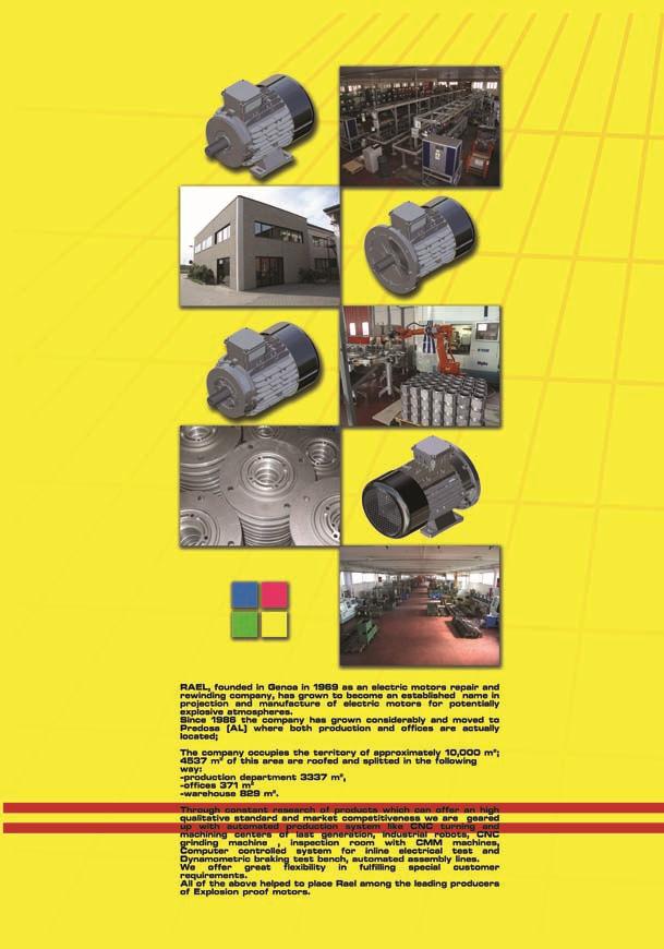
 Flame proof motors Ex d IIB ADPE Series ALUMINIUM Petrol station motors ADPE Ed.2008/01 1di 20 COMPANY PRESENTATION RAEL, founded in Genoa in 1969, is specialized since 1978 in the study, planning and
BFG range BFGC range BFN range
 BFG range BFGC range BFN range LOW AND MEDIUM VOLTAGE MOTORS FOR HAZARDOUS AREAS EEx d EEx de EEx na - Flameproof Motors - Flameproof Motors With Increased Safety Terminal Box - Non Sparking Motors TABLE
BFG range BFGC range BFN range
 BFG range BFGC range BFN range LOW AND MEDIUM VOLTAGE FOR HAZARDOUS AREAS EEx d EEx de EEx na - Flameproof Motors - Flameproof Motors With Increased Safety Terminal Box - Non Sparking Motors 1. MARKING
Explosion and flame-proof cast iron electric motors
 Explosion and flame-proof cast iron electric motors EEx-d, EEx-de, IIB, IIC II, 2G IP55 II, 2G&D IP66 T4, T5, T6 Frame size 56 to 160 3 phases Voltage 230/400 V 50Hz Voltage 265/460V 60Hz Types of mounting
Explosion and flame-proof single phase electric motors
 Explosion and flame-proof single phase electric motors EEx-d, EEx-de, IIB, IIC II, 2G IP55 II, 2G&D IP66 T4, T5, T6 Frame size 56 to 112 Single phase Voltage 230 50Hz Voltage 265 60Hz Types of mounting
VALIADIS S.A. HELLENIC MOTORS
 Explosion proof motors MAK 56-250 (MAKe 63-250) series Groups IIB and IIC Ex db / Ex db e (EPL) executions Gb or Ex tb IIIC (EPL) Db II 2 G, II 2D, 2GD SAFETY INSTRUCTIONS Safety Instructions MAK and MAKe
ATEX LABELLING FOR MOTORS AND GEAR UNITS
 ATEX LABELLING FOR MOTORS AND GEAR UNITS EN ATEX INFORMATION GAS AND DUST COMPLETE DRIVE SOLUTIONS FROM A SINGLE SOURCE RELIABLE n Reliable products n Coordinated components n NORD's own development and
Explosion proof electric motor For Fuel dispensing application. Main characteristic
 Ad-pe ed.2018/0 1 Explosion proof electric motor For Fuel dispensing application RAEL motori elettrici, since its inception in the late 60s, has assembled more than a million of explosion proof electric
Reg No: 1999/027771/07 ACCREDITED AND APPROVED TEST LABORATORY IN TERMS OF ARP 0108: REGULATORY REQUIREMENTS FOR EXPLOSION PROTECTED APPARATUS
 Government Approved Test Laboratory (Previously AIA) Reg No: 1999/027771/07 Equipment: Manufacturer: Type: ACCREDITED AND APPROVED TEST LABORATORY IN TERMS OF ARP 0108: REGULATORY REQUIREMENTS FOR EXPLOSION
Fans for ATEX EXPLOSIVE ATMOSPHERES
 Fans for ATEX EXPLOSIVE ATMOSPHERES An ATEX area is a mixture of air and inflammable gas, the vapour of an inflammable liquid, a fog of combustible liquid or combustible powder, which, if they catch fire,
FLSD (E) Atmospheres containing explosive GAS totally enclosed three-phase asynchronous motors General information
 Atmospheres containing explosive GAS totally enclosed three-phase asynchronous motors General information") (E) Atmospheres containing explosive GAS General information Flameproof totally enclosed three-phase asynchronous motors, FLSD (E) series, according to IEC 60034, 60038, 60072, 60079-0 and 60079-1, EN
(E) Atmospheres containing explosive GAS General information Flameproof totally enclosed three-phase asynchronous motors, FLSD (E) series, according to IEC 60034, 60038, 60072, 60079-0 and 60079-1, EN
INSTRUCTION MANUAL (ATEX / IECEx)
") INSTRUCTION MANUAL (ATEX / IECEx) BExBGL2D LED BEACON For use in Flammable Gas and Dust Atmospheres BExBGL2D 1) Warnings DO NOT OPEN WHEN AN EXPLOSIVE ATMOSPHERE IS PRESENT DO NOT OPEN WHEN ENERGIZED POTENTIAL
INSTRUCTION MANUAL (ATEX / IECEx) BExBGL2D LED BEACON For use in Flammable Gas and Dust Atmospheres BExBGL2D 1) Warnings DO NOT OPEN WHEN AN EXPLOSIVE ATMOSPHERE IS PRESENT DO NOT OPEN WHEN ENERGIZED POTENTIAL
SWE SERIES (IE3) WONDER ELECTRIC MOTOR (S) PTE LTD. Energy Saving Low Noise Environmental Friendly IEC Dimension Low Vibration European Design
 WONDER ELECTRIC MOTOR (S) PTE LTD. Energy Saving Low Noise Environmental Friendly IEC Dimension Low Vibration European Design") RANGE OF PRODUCTS Three phase asynchronous squirrel-cage & slip ring induction motors Three phase asynchronous self-braking motors Hollow shaft rotor motors Cooling tower motors High motors, (IE2) (IE3)
RANGE OF PRODUCTS Three phase asynchronous squirrel-cage & slip ring induction motors Three phase asynchronous self-braking motors Hollow shaft rotor motors Cooling tower motors High motors, (IE2) (IE3)
GOVERNMENT APPROVED TEST LABORATORY IN TERMS OF ARP 0108: REGULATORY REQUIREMENTS FOR EXPLOSION PROTECTED APPARATUS
 Reg No: 1999/027771/07 (Pty) Ltd 7 Spanner Rd / PO Box 467 Olifantsfontein 1665 Tel: +27 (11) 316 4601 Fax: +27 (11) 316 5670 E-mail: admin-mgr@explolabs.co.za GOVERNMENT APPROVED TEST LABORATORY IN TERMS
INSTRUCTION MANUAL (ATEX / IECEx)
") INSTRUCTION MANUAL (ATEX / IECEx) BExBG10D-P and BExBG15D-P Flameproof Xenon Beacons For use in Flammable Gas and Dust Atmospheres BExBG10D-P / BExBG15D-P 1) Warnings DO NOT OPEN WHEN AN EXPLOSIVE ATMOSPHERE
INSTRUCTION MANUAL (ATEX / IECEx) BExBG10D-P and BExBG15D-P Flameproof Xenon Beacons For use in Flammable Gas and Dust Atmospheres BExBG10D-P / BExBG15D-P 1) Warnings DO NOT OPEN WHEN AN EXPLOSIVE ATMOSPHERE
General Specifications. Cooling Method 3M series are IC 411 Standard. IC 416, IC 418 can be provided Upon request
 3M SERIES Three Phases Low Voltage Asynchronous Motors 3M Series Vilma motors are designed and manufactured with high quality materials and workmanship in order to meet demanding and arduous operation
Explosion protection. Air + combustible gas + ignition source = explosion. Air + combustible dust + ignition source = explosion
 Ex-protection Explosion protection Valves for fluid technology for use in explosion hazard areas Explosion protection for gas, dust and mining Flameproof enclosures and intrinsic safety Solutions for all
Cast Iron Frame Motors For Zone 21 Improved Efficiency EFF2
 Motors Energy Automation Coatings Cast Iron Frame Motors For Zone 21 Improved Efficiency EFF2 Standard Features: Three-phase, multivoltage, IP66, TEFC : 0.12 up to 250kW Frames: 63 up to 355M/L Voltage:
AEEB AEVB LOW VOLTAGE SERIES Three-Phase Squirrel Cage Induction Motor Conforming to SS530 (Occasional Use) Conforming to IE1
 Conforming to IE1") AEEB AEVB LOW VOLTAGE SERIES Three-Phase Squirrel Cage Induction Motor Conforming to SS530 (Occasional Use) Conforming to IE1 STANDARD AND SPECIFICATION Performance: Meet the requirement of Singapore standard
AEEB AEVB LOW VOLTAGE SERIES Three-Phase Squirrel Cage Induction Motor Conforming to SS530 (Occasional Use) Conforming to IE1 STANDARD AND SPECIFICATION Performance: Meet the requirement of Singapore standard
MINING ELECTRIC MOTORS 3KTCR, 4KTCR, 5KTCR
 MINING ELECTRIC MOTORS 3KTCR, 4KTCR, 5KTCR Explosion protection Certificate of Conformity: Frame size 71 and 160 Frame size 80, 90, 100, 112, 132 Frame size 180, 200, 225 Frame size 250 Frame size 280
Lenze ATEX-compliant gearboxes Gearboxes for use in potentially explosive atmospheres
 Lenze ATEX-compliant gearboxes Gearboxes for use in potentially explosive atmospheres ATEX for drive technology The ATEX directive, which has been in force since July 1, 2003, has been introduced in an
LSN Atmospheres containing explosive GAS totally enclosed three-phase asynchronous motors General information
 General information Non-sparking totally enclosed threephase asynchronous motors, LSN series, according to IEC 60034, 60072, IEC 60079-1 and 60079-15. Single speed: power 0.75 to 90 kw 1, frame size 80
Switches in conformity with ATEX directive
 Switches in conformity with ATX directive 2/3 General Catalog 3-4 Technical concepts page 2/39 Position switches FD series page 2/4 Category Zone PL Approvals 2G Gb Mb II 2G x ia IIC T6 Gb I x ia I Mb
ELECTRIC MOTORS. Selection. Starting torque and nominal torque
 SELECTION PROCEDURE The output powers published overleaf are based upon continuous maximum rating conditions. Therefore design factors for above average running periods do not normally affect the selection.these
Motors for Hazardous Areas
 3 Motors for Hazardous Areas 2G Ex e 2D Ex td A21 2GD Ex e Ex td A21 3G Ex na 3D Ex td A22 3GD Ex na Ex td A22 ALUMINIUM 56-160 ATEX . We have been supplying technology and solutions with constant quality
From 16 June 2011, motors placed for the first-time on the market shall have a minimum efficiency class of IE2.
 INTRODUCTION New efficiency classes for the low-voltage three-phase motors (IE = International Efficiency). Along with the international discussion on energy efficiency a worldwide harmonized energy efficiency
MINING ELECTRIC MOTORS 3KTCR AND 4KTCR
 MINING ELECTRIC MOTORS 3KTCR AND 4KTCR Explosion protection Certificate of Conformity: Frame size 71 and 160 Frame size 80, 90, 100, 112, 132 Frame size 180, 200, 225 Frame size 250 Frame size 280 Frame
SINGLE PHASE TEFC CAGE MOTORS
 SINGLE PHASE TEFC CAGE MOTORS 2 SINGLE PHASE TEF CAGE MOTORS Mechanical protection: IP 54 Voltage: 220 V, 50 Hz Type Output power P N kw Rated speed n N min -1 Efficiency % Power factor cos Rated current
Technical Documentation
 Technical Documentation EX09EN ELECTRIC OTORS IN EXPLOSION - PROOF PROTECTION INCREASED SAFETY EExe FLAEPROOF ENCLOSURE EExd Vision We set your ideas in motion. We do not merely manufacture motors, but
Precision. Consistently.
 Precision. Consistently. CONTENTS INDEX PRODUCT RANGE... 4 Standards & References Rating Plate Ambient Temperature... 5 Tolerance on Performance Parameters & Dimensions... 6 TERMINAL BOX DATA Effect of
ADVANTAGES. Air + combustible gas + ignition source = explosion. Air + combustible dust + ignition source = explosion
 EX-PROTECTION ADVANTAGES Valves for fluid technology for use in explosion hazard areas Explosion protection for gas, dust and mining Flameproof enclosures and intrinsic safety Solutions for all zones The
ELK PRODUCT CATALOGUE. elkmotor.com.tr
 ELK 0501-0418 PRODUCT CATALOGUE elkmotor.com.tr THREE PHASE SQUIRREL CAGE ASYNCHRONOUS MOTORS ELK Motor has been founded by major shareholders of Yılmaz Reduktor, as a continuation of the product family.
Table of contents. Technical informations > ATEX Page Technical informations Page Mechanically operated valves Page 13-06
 Technical informations > Table of contents ATEX Page 13-02 Technical General informations information Page 13-02 Mechanically operated valves Page 13-06 Pneumatically operated valves Page 13-06 Electrically
BROCHURE. Low voltage motors and drives for applications in explosive atmospheres
 BROCHURE Low voltage motors and drives for applications in explosive atmospheres 2 ABB LOW VOLTAGE MOTORS AND DRIVES FOR APPLICATIONS IN EXPLOSIVE ATMOSPHERES ABB LOW VOLTAGE MOTORS AND DRIVES FOR APPLICATIONS
Energy Saving Three Phase Motors
 e-drive Energy Saving Three Phase Motors IEC frames 56 to 400 Outputs 0.09 to 630 IE2 MEPS2006 Type: AHE Aluminium Motors Type: HE Cast-Iron Motors 1 When you need all the features of a premium quality
Switches in conformity with ATEX directive
 Switches in conformity with ATX directive 2/3 General Catalog -2 Technical concepts page 2/39 Position switches FD series page 2/4 Category Zone PL Approvals 2G Gb Mb II 2G x ia IIC T6 Gb I x ia I Mb Article
GOVERNMENT APPROVED TEST LABORATORY IN TERMS OF ARP 0108: REGULATORY REQUIREMENTS FOR EXPLOSION PROTECTED APPARATUS
 Reg No: 1999/027771/07 (Pty) Ltd 7 Spanner Rd / PO Box 467 Olifantsfontein 1665 Tel: +27 (11) 316 4601 Fax: +27 (11) 316 5670 E-mail: admin-mgr@explolabs.co.za GOVERNMENT APPROVED TEST LABORATORY IN TERMS
EXPLOSION-PROOF MOTORS SINGLE PHASE
 AC Motors MOTORS SINGLE PHASE Underwriters Laboratories and Canadian Standards Association Listed These explosion proof motors are designed and approved for application in hazardous environments having
xplosion Proof Motors hoyermotors.com Explosion Proof
 Explosion Proof Motors hoyermotors.com xplosion Proof Behind Hoyer Motors Svend Hoyer A/S is an international company comprising the two business units Hoyer Motors and Hoyer Transmissions. Headquartered
Modular Explosion Proof Brakes. IECLine rev 0
 Modular Explosion Proof Brakes IECLine 2013 rev 0 Application example Standard B5 motor + VIS brake Standard B5 motor + VIS brake + gearbox unit Main Characteristics -PATENT pending design and concept
CORE VALUES TECHNOLOGIES ESS-ESD PRODUCT CATALOGUE Enjoy the peace of mind ENGINE POWER SUPPLIERS AND EQUIPMENT HEAT
 TECHNOLOGIES ENGINE POWER SUPPLIERS AND EQUIPMENT HEAT Enjoy the peace of mind ESS-ESD PRODUCT CATALOGUE CORE VALUES PEACE OF MIND EFFICIENCY FAIRNESS RESPONSIBILITY CUSTOMER ORIENTATION GROWING DEVELOPED
Series E4F E5F
 Three Phase Induction Motors With Rotors Wound for Hoists Series E4F 160-315 E5F 355-400 ASI NT 003.1 I N D E X Use 2 Electrical Tolerances 9 Mechanical Tolerances 9 General Characteristics 2 Technical
AESV / AESU / AESV-LA Series Squirrel Cage Induction Motor AESV1S / AESU1S / AESV1S-LA (IE1) STANDARD EFFICIENCY
 STANDARD EFFICIENCY") AESV / AESU / AESV-LA Series Squirrel Cage Induction Motor AESV1S / AESU1S / AESV1S-LA (IE1) STANDARD EFFICIENCY AESV2S / AESU2S / AESV2S-LA (IE2) HIGH EFFICIENCY AESV3S / AESU3S / AESV3S-LA (IE3) PREMIUM
AESV / AESU / AESV-LA Series Squirrel Cage Induction Motor AESV1S / AESU1S / AESV1S-LA (IE1) STANDARD EFFICIENCY AESV2S / AESU2S / AESV2S-LA (IE2) HIGH EFFICIENCY AESV3S / AESU3S / AESV3S-LA (IE3) PREMIUM
Petroleum industries are dealing with different hazardous materials starting from storing, processing and distributing the petroleum products These he
 FIRE SAFETY OF PETROLEUM INDUSTRIES By- Debapriya Biswas Additional Director General West Bengal Fire & Emergency Services Petroleum industries are dealing with different hazardous materials starting from
FCR asynchronous brake motors LS FCR. General information
 General information LIFTING USE : U.L. Enclosed three-phase asynchronous brake motors, LS series with failsafe brake, according to IEC 34, 72, EN 50281. Single speed : 0.55 to 15, frame size from 80 to
High voltage flameproof induction motors The simplest solution for hazardous environments
 High voltage flameproof induction motors The simplest solution for hazardous environments We offer motors and generators, services and expertise that save energy and improve our customers processes over
LARGE THREE-PHASE SQUIRREL CAGE ASYNCHRONOUS MOTORS FOR HEAVY DUTY APPLICATIONS ADH SERIES
 LARGE THREE-PHASE SQUIRREL CAGE ASYNCHRONOUS MOTORS FOR HEAVY DUTY APPLICATIONS ADH SERIES FRAMES 355 560 355kW 1500kW (1500rpm) FOR INVERTER DUTY Code Declaration of conformity The motors described in
Product Overview. Rotary Encoders for Potentially Explosive Atmospheres (ATEX)
") Product Overview Rotary Encoders for Potentially Explosive Atmospheres (ATEX) December 2013 Rotary encoders for use in potentially explosive areas Introduction There are many types of applications in industry
Product Overview Rotary Encoders for Potentially Explosive Atmospheres (ATEX) December 2013 Rotary encoders for use in potentially explosive areas Introduction There are many types of applications in industry
champion series motors
 Introducing A brand new series of Super Performers Data Sheet champion series motors FRAME SIZE 63-132M TEFC 3 Phase Squirrel Cage Induction Motors Siemens CHAMPION Series Cage Motors are suitable for
CPLS Asynchronous motors for variable frequency. 95 Nm to 2900 Nm
 95 Nm to 2900 Nm Introduction The range of IP23 protection CPLS asynchronous motors was designed for fixed and variable speed applications when there is little space available or (and) there is a wide
ILED Dorado. User Manual
 10NM U-code Medium Intensity Obstruction Light Helideck Status Light 15NM U-code Contents 1. Safety... 3 2. Warranty... 3 2.1 General... 3 2.2 Life span... 3 3. Type plate... 4 4. Product Description...
GOVERNMENT APPROVED TEST LABORATORY IN TERMS OF ARP 0108: REGULATORY REQUIREMENTS FOR EXPLOSION PROTECTED APPARATUS
 Reg No: 1999/027771/07 (Pty) Ltd 7 Spanner Rd / PO Box 467 Olifantsfontein 1665 Tel: +27 (11) 316 4601 Fax: +27 (11) 316 5670 E-mail: admin-mgr@explolabs.co.za GOVERNMENT APPROVED TEST LABORATORY IN TERMS
Squirrel Cage Induction Motors MA - A4 - BB - B4 - B5 SERIES SIZES. MarelliMotori ASI.CT.033.2
 Marine Motors Three Phase Squirrel Cage Induction Motors MA - A4 - BB - B4 - B5 SERIES 63-400 SIZES MarelliMotori ASI.CT.033.2 CONTENTS Page STANDARDS 5 ESSENTIAL AND NON-ESSENTIAL SERVICE 5 CLASSIFICATION
GuaRdboX - Gd series IOM (Installation, Operation & Maintenance Manual) 0100-ENG rev.4
 0100-ENG rev.4") 1. Introduction: This instruction manual contains important information regarding the safety instructions, installation, operation, maintenance and storage of the Guardbox limit switch boxes. The limit
1. Introduction: This instruction manual contains important information regarding the safety instructions, installation, operation, maintenance and storage of the Guardbox limit switch boxes. The limit
PLS Open Drip Proof three-phase asynchronous motors. General information
 General information Open Drip Proof three-phase asynchronous motors, series PLS, according to IEC 60034, 60066, 60072 power 7,5 kw to 900 kw, frame size 160 to 400 mm, 2, 4, 6 and 8 ; 230/400 V or 400
Industrial Performance Motors. New Aluminum and Cast Iron Motors. Flexibility
 Industrial Performance Motors New Aluminum and Cast Iron Motors Flexibility Low Voltage Industrial Performance Motors Flexibility Industrial performance motors offer the flexibility needed by most of our
Explosion-proof motors
 /2 Orientation /2 Overview /3 Benefits /3 Application /3 Technical specifications /5 Selection and ordering data /7 More information /12 Self-ventilated motors in Zone 1 with type of protection "e" Aluminium
TYPE 2 poles 4 poles 6 poles 8 poles 2 / 4 poles 4 / 8 poles 2 / 8 poles 4 / 16 poles
 BAH-BAHS series Overwiew MGM Electric Motors was established in 1950 as a brake motors manufacturer. MGM is today a world leading manufacturer of this line of products. MGM brake motors are designed and
K Series 3 Way Direct Acting Balanced Poppet Solenoid Valve
 Ex d Ex m IP5 Series 3 Way Direct Acting Balanced Poppet Solenoid Valve DB2S-M2C \ Ex d IIC with Integral Stainless \ Steel Junction Box. \ Valve. \ Manual Override, Option M2. J77072S-M2 \ Ex m II NASS
ODP SERIES PREMIUM INDUSTRIAL OPEN DRIP PROOF MOTORS C280M to C355LB Frame. Australian Version October 2013
 ODP SERIES PREMIUM INDUSTRIAL OPEN DRIP PROOF MOTORS C280M to C355LB Frame Australian Version October 2013 ODP SERIES (OPEN DRIP PROOF) PREMIUM INDUSTRIAL OPEN DRIP PROOF MOTORS, C280M TO C355LB FRAME
SPOOL VALVES solenoid air operated 1/4 to 1/2 tapped body and NAMUR for integrated pilot
 SPOOL VALVES operated / to / tapped body and NAMUR for integrated pilot ATEX /-/ Series - FEATURES The valves offer environmental protection against the ingress of liquids, dusts or other foreign matter
MVSI. Technical features
 MVSI The MVSI series represents the line of reference products for manufacturer s of vibrating machines and plants operating in many industrial sectors and is made up of the largest range on the market,
Installation & Maintenance Manual
 Installation & Maintenance Manual Techtop Industries, Inc. 1268 Old Alpharetta Road Alpharetta, GA 30005 www.techtop.com info@techtopind.com Before you install, operate or perform maintenance, become familiar
Ex m Solenoid Operator Type 0519
 nass magnet GmbH Eckenerstrasse 4-6 D-30179 Hannover Doc. No. 113-720-0002 Revision No. 2 01.06.2015 Ex m Solenoid Operator Type 0519 Operating Instructions Dear Customer! To ensure the function and for
: B3; B5; B14; B34; B35; V1
 ATT WE series (Eff1) are 3-phase TEFC Cast-Iron high efficiency general purpose induction motors, which are designed to meet or exceed the requirements for energy efficiency such as: European Eff1, Australia
Ordering information. When placing an order, specify motor type, size and product code according to the following example.
 Ordering information When placing an order, specify motor type, size and product code according to the following example. Example Motor type M3AA 112 MB Pole number 4 Mounting arrangement (IM-code) IM
IP66 GSW GEAR BOX MOTOR SERIES
 IP66 GSW GEAR BOX MOTOR SERIES Three Phase Aluminium Gear Box Motors Australian Version October 2013 CONTENTS INTRODUCTION Pg 3 MATERIALS AND CONSTRUCTION Pg 3-4 SERIES OVERVIEW Pg 5 PERFORMANCE DATA Pg
LSES high efficiency three-phase asynchronous motors. General information
 Efficiency class IE2 General information Totally enclosed three-phase saving asynchronous motors, series, according to IEC 60034, 60038, 60072 ; 0.75 to 200 kw, frame size 80 to 315 mm. Single speed: 2,4
Ex e, ia Junction boxes TNCN. Features
 TNCN Features The TNCN/TNCC range comprises many standard sizes of enclosure manufactured in 316L acid resistant stainless steel to give the maximum environmental protection. The main body is manufactured
CONTENTS 1 GENERAL 2 STANDARDS. 3 TECHNICAL FEATURES 3.1 Basic Technical Data 3.2 Standard Accessories 3.3 Tolerances
 CONTENTS 1 GENERAL 2 STANDARDS 3 TECHNICAL FEATURES 3.1 Basic Technical Data 3.2 Standard Accessories 3.3 Tolerances 4 MOTOR DESIGN 4.1 Stator Casing 4.2 Stator Core with Winding 4.3 Stator Winding 4.4
Three-phase asynchronous motors
 Three-phase asynchronous motors for low voltage with squirrel-cage rotor Product specification Series K11R, K21R and K22R Introduction Standards and regulations Progressive correspondence between output
SERVICE AND EXPLOITATION INSTRUCTION MANUAL
 Edition: April 2007r. SERVICE AND EXPLOITATION INSTRUCTION MANUAL for three-phase, explosion-proof, increased safety, squirrel - cage induction motors: of frame size 56, 63, 71, 80, according to requirements
CONTENTS 1 GENERAL 2 STANDARDS. 3 TECHNICAL FEATURES 3.1 Basic Design Data 3.2 Standard Accessories 3.3 Tolerances
 CONTENTS 1 GENERAL 2 STANDARDS 3 TECHNICAL FEATURES 3.1 Basic Design Data 3.2 Standard Accessories 3.3 Tolerances 4 MOTOR DESIGN 4.1 Stator Casing 4.2 Stator Core with Winding 4.3 Stator Winding and Insulation
Low Voltage General Purpose Motors
 Low Voltage General Purpose Motors Making you more competitive ABB s General purpose motor is designed for use in general industry, meeting the demands of standard applications for OEM's. Motors are readily
AESV / AESU / AESV-LA Series Squirrel Cage Induction Motor AESV1S / AESU1S / AESV1S-LA (IE1) STANDARD EFFICIENCY
 STANDARD EFFICIENCY") AESV / AESU / AESV-LA Series Squirrel Cage Induction Motor AESV1S / AESU1S / AESV1S-LA (IE1) STANDARD EFFICIENCY AESV2S / AESU2S / AESV2S-LA (IE2) HIGH EFFICIENCY AESV3S / AESU3S / AESV3S-LA (IE3) PREMIUM
AESV / AESU / AESV-LA Series Squirrel Cage Induction Motor AESV1S / AESU1S / AESV1S-LA (IE1) STANDARD EFFICIENCY AESV2S / AESU2S / AESV2S-LA (IE2) HIGH EFFICIENCY AESV3S / AESU3S / AESV3S-LA (IE3) PREMIUM
THREE-PHASE ASYNCHRONOUS MOTORS EFFICIENCY CLASS ACCORDING IEC
 THREE-PHASE ASYNCHRONOUS MOTORS EFFICIENCY CLASS ACCORDING IEC 60034-30 1st EDITION IE1/IE2-MS IE1/IE2-EG Series IE1 Standard efficiency IE2 High efficiency THREE-PHASE ASYNCHRONOUS MOTORS EFFICIENCY CLASS
LSPXMV FCR Atmospheres containing explosive dust FCR asynchronous brake motors. General information
 General information GENERAL USE : U.G. Enclosed three-phase brake asynchronous motors, LSPXMV series with failsafe brake, according to IEC 6003, 60072, EN 50281. Single speed : 0.25 to 11, frame size from
Category 1 (zone 0) covers areas, where there is a permanent or long lasting occurrence
 covers areas, where there is a permanent or long lasting occurrence") Explosion proof fans General Systemair explosion proof fans have been developed to be used in effective supply and exhaust air systems allocated to category 2 (zone 1) and category 3 (zone 2) in explosion
Explosion proof fans General Systemair explosion proof fans have been developed to be used in effective supply and exhaust air systems allocated to category 2 (zone 1) and category 3 (zone 2) in explosion
INDUSTRY PROCESS AND AUTOMATION SOLUTIONS. Technical Bulletin
 INDUSTRY PROCESS AND AUTOMATION SOLUTIONS Technical Bulletin Guidelines for selection of planetary gear units of the 300- INDUSTRIAL series for installation in hazardous areas, classified by Directive
List Price. Mult. Sym. C Dim. Single Phase
 Single and Three Phase, Foot Mounted Explosion Proof 1/4 thru 300 48 thru 449TY Applications: Ideal for use where hazardous fumes or dust may be present. Features: U.L. and CSA approved for Class I, Group
1/4 thru 300 Hp NEMA 48 thru 449TY. List Price. Mult. Sym. C Dim. Single Phase
 Single and Three Phase, Foot Mounted Explosion Proof 1/4 thru 300 48 thru 449TY Applications: Ideal for use where hazardous fumes or dust may be present. Features: U.L. and CSA approved for Class I, Group
THREE PHASE ASYNCHRONOUS MOTORS. MS/S Series (frame Aluminum) TC Series (frame Cast iron) Y Series (frame Cast iron)
 TC Series (frame Cast iron) Y Series (frame Cast iron)") THREE PHASE ASYNCHRONOUS MOTORS MS/S Series (frame 56-200 Aluminum) TC Series (frame 160-355 Cast iron) Y Series (frame 132-355 Cast iron) INDICE 01. General features p.03 02. Standards p.04 03. Mounting
THREE PHASE ASYNCHRONOUS MOTORS MS/S Series (frame 56-200 Aluminum) TC Series (frame 160-355 Cast iron) Y Series (frame 132-355 Cast iron) INDICE 01. General features p.03 02. Standards p.04 03. Mounting
Protection against mechanical impacts IK 08 according to IEC 68, EN Insulation class Class F (155 C), class H (180 C) on request.
, class H (180 C) on request.") MVSI The MVSI series represents the line of reference products for manufacturer s of vibrating machines and plants operating in many industrial sectors and is made up of the largest range on the market,
MVSI The MVSI series represents the line of reference products for manufacturer s of vibrating machines and plants operating in many industrial sectors and is made up of the largest range on the market,
Aluminium Frame Motors Improved Efficiency EFF2
 Motors Energy Automation Coatings Aluminium Frame Motors Improved Efficiency EFF2 Standard Features: Three-phase, multivoltage, IP55, TEFC : 0.12 up to 11kW Frames: 63 up to 132M Voltage: 220-240/380-415V
THREE-PHASE SQUIRREL-CAGE INDUCTION MOTORS EXPLOSION-PROOF FRAME
 MASZYNY ELEKTRYCZNE CELMA SA ISO 9001: 2000 ISO 14001 THREE-PHASE SQUIRREL-CAGE INDUCTION MOTORS EXPLOSION-PROOF FRAME 80 132 Type: ECS(K,L,1)g, ECS(K,L,1)gb CS(K,L,1)g, CS(K,L,1)gb GENERAL INFORMATION
Motors and drives for applications in explosive atmospheres
 Motors and drives for applications in explosive atmospheres Certification. Diligence. Reliability. Safety. Everything counts Operating processes in explosive (Ex) atmospheres requires the right mix of
Asynchronous, Low Voltage, Squirrel Cage, Three Phase Electric Motors
 Asynchronous, Low Voltage, Squirrel Cage, Three Phase Electric Motors Series R2, Frame 63 355 Introduction KHM R2 series cast iron motors are totally enclosed fan cooled, 3 phase, and squirrel cage induction
Flameproof Enclosures
 Flameproof Enclosures The range comprises many standard sizes of enclosures manufactured in stainless steel 316L and/or in painted carbon steel. The enclosures allow for utilization of standard electrical
End Suction Range MARCH 2018
 End Suction Range MARCH 2018 INDEX QB Peripheral Vane Pump... 4 Performance Data... 5 CPM Single Stage Pumps... 6 2CPM Twin Stage Pump... 10 Performance Data... 11 JSWM Self-Priming Jet Pump... 12 Performance
Variable speed asynchronous motors with FCPL brake LSMV FCPL. General information
 General information GENERAL USE : U.G. Enclosed three-phase asynchronous brake motors, LSMV series with failsafe continuous current (dc) brake, according to IEC 60034, 60072, EN50281. Separate mains supply
Hazardous Location Enclosures INDEX. Hazardous Location Enclosures HAZ-2
 Hoffman s new ZonEX ATEX-certified enclosures can be used in Zone 1- and Zone 2-rated applications throughout the world. Our NEMA Type 9 enclosures are designed for use in Class II Division 1 and 2 locations
Proportional pressure reducing valves type DHRZO and DHRZA standard and ex-proof version, direct operated, ISO 4401 size 06
 www.atos.com Table TF040-2/E Proportional pressure reducing valves type DHRZO and DHRZA standard and ex-proof version, direct operated, ISO 4401 size 06 A B DHRZO-A-012/25 A B DHRZA-A-010/25 DHRZ* are
Three-phase roller table motors with squirrel-cage rotor for the application at the frequency converters Series A21O, A20O, ARB, ARC.
 Three-phase roller table motors with squirrel-cage rotor for the application at the frequency converters Series A21O, A20O, ARB, ARC Product summary VEM motors GmbH Introduction Roller table motors are
SERIES R - MD MOR & GOR
 SERIES R - MD MOR & GOR CHARACTERISTICS OPTIONS Aluminium alloy construction Surface protection treatment (anodising, only for ATEX 2 versions) Available in monoblock execution (MOR) and with coupling
NEMA explosion-proof AC motors. Individual solutions are our standard
 NEMA explosion-proof AC motors Individual solutions are our standard BARTEC VARNOST The plant itself came into being in 1957 as one of the small working units of the Zagorje coal mine. Five years later,
INDEX MVSI MVSI-TS MVSI-ACC MVSI-E MVSS CDX MVTX MICRO M3 MVCC MTF MTF-E MVB MVB-E-FLC VB-E ITV-VR ITVAF VIBRAVAR CFV MULTIVAR
 IDEX Certifications page 3 Foot mounted electric vibrators MVSI MVSI-TS MVSI-CC MVSI-E MVSS CDX MVTX MICRO M3 M3-E MVCC Electric vibrators page 6 Electric vibrators with split covers page 16 xial coupling
by Jim Phillips, P. E.
 by Jim Phillips, P. E. Baking flour, coal dust and gasoline; what do these things have in common? They are not the ingredients for a strange new cake recipe. Each of these ingredients is the fuel that
Three-phase asynchronous motors with squirrel-cage rotor for potentially explosive atmospheres
 Three-phase asynchronous motors with squirrel-cage rotor for potentially explosive atmospheres VEM motors GmbH Table of contents Page Technical explications Motors in the increased safety type of protection
General Purpose Cast Iron Motors
 General Purpose Cast Iron Motors Totally enclosed squirrel cage three phase low voltage motors, Sizes 71-355, 0.25 to 250 kw www.abb.com/motors&drives > Motors > Low voltage motors > General purpose motors