T thru T (LC41 550FG) thru 41800, thru
|
|
|
- Amice O’Neal’
- 5 years ago
- Views:
Transcription

1 Single Engine Service Bulletin January 12, 2011 SB TITLE ENGINE TURBOCHARGER HOUSING INSPECTION EFFECTIVITY Model Serial Numbers T182T T thru T (LC41 550FG) thru 41800, thru Also affected are engines and turbochargers in Service Facility stock. REASON The purpose of this Service Bulletin is to transmit the attached Hartzell Engine Technologies (HET) Mandatory Service Bulletin No. 040 A, Turbocharger CHRA Contamination, Teledyne Continental Aircraft Engine Service Bulletin SB10-8, Hartzell Engine Technologies Service Bulletin Turbocharger CHRA contamination, and Lycoming Mandatory Service Bulletin No. 594 Reprint of Hartzell Engine Technologies LLC (HET) (formerly Kelly Aerospace) Mandatory Service Bulletin 040 A. DESCRIPTION HET has become aware of a condition that affects certain turbocharger center housing rotating assemblies (CHRA) where debris may not have been removed after a machining operation. The debris could enter the normal oil flow to the turbine wheel shaft assembly resulting in seizure of the shaft and/or turbine wheel head separation. This condition may also lead to a loss of engine oil. Either condition may lead to a complete loss of turbocharger function without warning as well as a partial or complete loss of engine power. Since this debris is expected to enter the oil stream quickly, the effects listed above can also occur quickly. Lycoming Mandatory Service Bulletin No. 594 transmits HET Mandatory Service Bulletin No. 040 A. Teledyne Continental Aircraft Engine Service Bulletin SB10-8 transmits HET Mandatory Service Bulletin No Page 1 of 4 To obtain satisfactory results, procedures specified in this publication must be accomplished in accordance with accepted methods and prevailing government regulations. Cessna Aircraft Company cannot be responsible for the quality of work performed in accomplishing the requirements of this publication. Cessna Aircraft Company, Customer Service, P.O. Box 7706, Wichita, Kansas 67277, U.S.A. (316) , Facsimile (316) COPYRIGHT 2011
2 COMPLIANCE Mandatory: For turbochargers having between 0 and 10 hours time in service (TIS) including field overhauls, before further flight perform the IDENTIFICATION section of HET Mandatory Service Bulletin No. 040 A (or latest revision). If the CHRA center housing is affected, remove the turbocharger in order to proceed to the DISASSEMBLY and CLEANING sections of HET Mandatory Service Bulletin No. 040 A (or latest revision) and perform the required actions. For turbochargers having between 10 and 50 hours TIS including field overhauls: Within the next ten (10) hours time in service perform the IDENTIFICATION section of HET Mandatory Service Bulletin No. 040 A (or latest revision). If the CHRA center housing is affected, remove the turbocharger in order to proceed to the DISASSEMBLY and CLEANING sections of HET Mandatory Service Bulletin No. 040 A (or latest revision) and perform the required actions. For turbochargers operated beyond 50 hours time in service, including field overhauled, no action is required. APPROVAL Refer to HET Mandatory Service Bulletin No. 040 A, Teledyne Continental Aircraft Engine Service Bulletin SB10-8, and Lycoming Mandatory Service Bulletin No MANPOWER Not determined REFERENCES Applicable Cessna Airplane Maintenance Manuals and Illustrated Parts Catalogs. Refer to Current HET Mandatory Service Bulletin No. 040 A (or latest revision). Refer to service_bulletins.html. Current Teledyne Continental Aircraft Engine Service Bulletin SB10-8 (or latest revision). Refer to tcmlink.com/infoservices. Current Lycoming Mandatory Service Bulletin No. 594 (or latest revision). Refer to lycoming.textron.com. MATERIAL Refer to HET Mandatory Service Bulletin No. 040 A, Teledyne Continental Aircraft Engine Service Bulletin SB10-8, and Lycoming Mandatory Service Bulletin No CREDIT Refer to HET Mandatory Service Bulletin No. 040 A (or latest revision), Teledyne Continental Aircraft Engine Service Bulletin SB10-8, and Lycoming Mandatory Service Bulletin No SB Page 2 January 12, 2011
3 ACCOMPLISHMENT INSTRUCTIONS NOTE: Airplanes equipped with a Lycoming engine, accomplish Step 1. NOTE: Airplanes equipped with a Teledyne Continental engine, accomplish Step Airplanes equipped with a Lycoming engine, do as follows: A. Review and accomplish the attached Lycoming Mandatory Service Bulletin No. 594 and HET Mandatory Service Bulletin No. 040 A Turbocharger CHRA Contamination (or latest revisions). B. Make appropriate entries in the airplane and engine logbooks stating compliance with this Service Bulletin, Lycoming Mandatory Service Bulletin No. 594, and HET Mandatory Service Bulletin No. 040 A (or latest revisions). 2. Airplanes equipped with a Teledyne Continental engine, do as follows: A. Review and accomplish the attached Teledyne Continental Aircraft Engine Service Bulletin SB10-8 and HET Mandatory Service Bulletin No. 040 A Turbocharger CHRA Contamination (or latest revisions). B. Make appropriate entries in the airplane and engine logbooks stating compliance with this Service Bulletin, Teledyne Continental Aircraft Engine Service Bulletin SB10-8, and HET Mandatory Service Bulletin No. 040 A (or latest revisions). NOTE: This information shall be considered an amendment to the Cessna Manufacturer's Service/Maintenance Manual or Instructions for Continued Airworthiness and must be accomplished for ongoing airworthiness compliance as necessary in accordance with 14 CFR Part SB January 12, 2011 Page 3
4 OWNER NOTIFICATION On January 12, 2011 the following message will be sent to applicable owners of record in SB A. Dear Cessna Restart Owner: This Owner Advisory is to inform you that SB Engine Turbocharger Housing Inspection has been issued to transmit the Hartzell Engine Technologies (HET) Mandatory Service Bulletin No. 040 A, Turbocharger CHRA Contamination, Teledyne Continental Aircraft Engine Service Bulletin SB10-8, Hartzell Engine Technologies Service Bulletin Turbocharger CHRA contamination, and Lycoming Mandatory Service Bulletin No. 594 Reprint of Hartzell Engine Technologies LLC (HET) (formerly Kelly Aerospace) Mandatory Service Bulletin 040 A. HET has become aware of a condition that affects certain turbocharger center housing rotating assemblies (CHRA) where debris may not have been removed after a machining operation. The debris could enter the normal oil flow to the turbine wheel shaft assembly resulting in seizure of the shaft and/or turbine wheel head separation. This condition may also lead to a loss of engine oil. Either condition may lead to a complete loss of turbocharger function without warning as well as a partial or complete loss of engine power. Since this debris is expected to enter the oil stream quickly, the effects listed above can also occur quickly. Lycoming Mandatory Service Bulletin No. 594 transmits HET Mandatory Service Bulletin No. 040 A. Teledyne Continental Aircraft Engine Service Bulletin SB10-8 transmits HET Mandatory Service Bulletin No Mandatory: For turbochargers having between 0 and 10 hours time in service (TIS) including field overhauls, before further flight perform the IDENTIFICATION section of HET Mandatory Service Bulletin No. 040 A (or latest revision). If the CHRA center housing is affected, remove the turbocharger in order to proceed to the DISASSEMBLY and CLEANING sections of HET Mandatory Service Bulletin No. 040 A (or latest revision) and perform the required actions. For turbochargers having between 10 and 50 hours TIS including field overhauls: Within the next ten (10) hours time in service perform the IDENTIFICATION section of HET Mandatory Service Bulletin No. 040 A (or latest revision). If the CHRA center housing is affected, remove the turbocharger in order to proceed to the DISASSEMBLY and CLEANING sections of HET Mandatory Service Bulletin No. 040 A (or latest revision) and perform the required actions. For turbochargers operated beyond 50 hours time in service, including field overhauled, no action is required. The information contained in the referenced Cessna Service Bulletin must be considered an amendment to the Cessna Manufacturer's Service/Maintenance Manual or Instructions for Continued Airworthiness, and must be accomplished for ongoing Airworthiness Compliance as required per 14 CFR Part Please contact a Cessna Single Engine Authorized Service Facility for detailed information and arrange to have Cessna Service Bulletin SB accomplished on your airplane. * * * * * * * SB Page 4 January 12, 2011
5 2900 Selma Highway Montgomery, AL USA Tel: Fax: Service Bulletin Compliance is Considered Mandatory Bulletin No. 040 A Issue Date: Dec. 22, 2010 TURBOCHARGER CHRA CONTAMINATION REASON FOR REVISION: TIO-541-E1C4 for Beech A60 Duke. To revise Table 2, Cessna 421B - TSIO-520-H, should be GTSIO-520-H, added INTRODUCTION: Hartzell Engine Technologies LLC (HET) has become aware of a condition affecting certain turbocharger center housing rotating assemblies (CHRA) where debris may not have been removed after the machining operation. The debris could enter the normal oil flow to the turbine wheel shaft assembly resulting in seizure of the shaft and/or turbine wheel head separation. This condition may also lead to a loss of engine oil. Either condition may lead to a complete loss of turbocharger function without warning as well as a partial or complete loss of engine power. Since this debris is expected to enter the oil stream quickly, the effects listed above can also occur quickly. The instructions herein identify the two manufacturing sources for the CHRA center housings of which only one is affected. This Service Bulletin is being issued to mandate the cleaning of CHRA center housing of turbochargers according to Table 1 below. COMPLIANCE: For turbochargers having between 0 and 10 hours time in service (TIS) including field overhauls, before further flight perform the IDENTIFICATION section of this procedure. If the CHRA center housing is affected, remove the turbocharger in order to proceed to the DISASSEMBLY and CLEANING sections and perform the required actions. For turbochargers having between 10 and 50 hours time in service (TIS) including field overhauls: Within the next ten (10) hours time in service, perform the IDENTIFICATION section of this procedure. If the CHRA center housing is affected, remove the turbocharger in order to proceed to the DISASSEMBLY and CLEANING sections and perform the required actions. For turbochargers operated beyond 50 hours time in service, including field overhauled: No action is required. EFFECTIVITY: Any aircraft or engine utilizing new (-0000 series) or rebuilt (-9000 series), turbochargers, manufactured before serial number H-NJL00003 (new) or H-NJR00002 (rebuilt) with the compliance times above. See Table 1a & 1b for applicable part numbers Applications may include but are not limited to those specified in Table 2. If you have any questions concerning the instructions in this service bulletin, please contact Hartzell Engine Technologies Technical Support at Questions concerning aircraft service or operation must be forwarded to the applicable manufacturer of that product. Rev. A Hartzell Engine Technologies Service Bulletin 040 Page 1 of 9
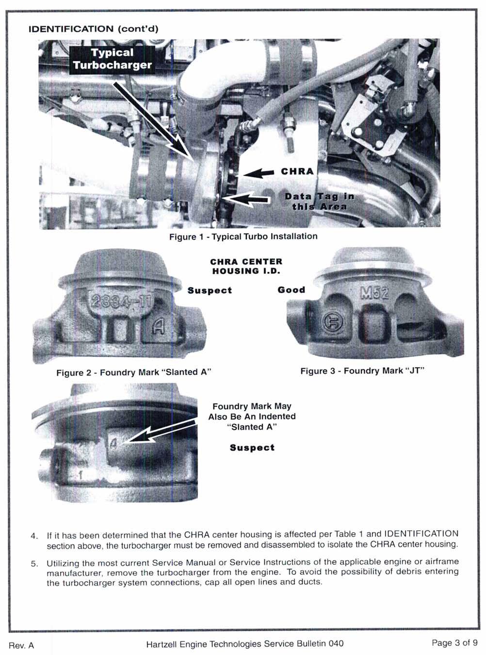
6 EFFECTIVITY: (cont d) Table 1a - Applicable KAES Part Numbers (Turbocharger) Table 1b - Applicable Original Equipment (OE) Part Numbers (Turbochargers) The turbocharger part numbers above or below may appear on the data tag C C C22924 C C LW LW LW IDENTIFICATION WARNING: THIS PROCEDURE MUST BE PERFORMED BY COMPETENT AND QUALIFIED PERSONNEL FAMILIAR WITH ENGINE AND AIRFRAME MAINTENANCE THAT IS SPECIFIC TO THE TURBOCHARGING SYSTEM. FAILURE TO DO SO MAY RESULT IN ECONOMIC LOSS, EQUIPMENT DAMAGE, AND/OR PHYSICAL INJURY. CAUTION: DO NOT DEPEND ON THIS SERVICE BULLETIN FOR GAINING ACCESS TO THE AIRCRAFT OR ENGINE. THIS WILL REQUIRE THAT YOU USE THE APPLICABLE MANUFACTURER S MAINTENANCE MANUALS OR SERVICE INSTRUCTIONS. IN ADDITION, ANY PREFLIGHT OR IN FLIGHT OPERATIONAL CHECKS REQUIRE USE OF THE APPROPRIATE AFM OR POH. 1. Access the aircraft turbocharger(s) in accordance with the instructions in the aircraft maintenance manual. Some aircraft engines have two turbochargers, so check both. (Do not rely on the aircraft or engine paperwork alone to identify the turbocharger part number.) 2. Refer to Table I to determine if the turbocharger being inspected is an affected part number. Observe the part number found on the data plate. If the affected part number does not appear, go to the Return to Service section step 3 & 4. If an affected part number does appear, continue with step 3. (See Figure 1 for typical turbocharger installation.) 3. Using Figures 2, 3, and 4, identify the foundry mark located on the CHRA center housing as shown. Those with a circled JT are not affected and may proceed to the Return to Service section step 3 & 4. If a slanted A appears, continue with the DISASSEMBLY and CLEANING sections. NOTE: For engine or aircraft models, reference Table 2. It should be used for identifying turbocharged aircraft as a guide only. Not every aircraft or engine combination is listed and not every STC or other field application is included. This list is provided to help identify which aircraft may be affected by this service bulletin. Page 2 of 9 Hartzell Engine Technologies Service Bulletin 040 Rev. A
7 IDENTIFICATION (cont d) Typical Turbocharger C H R A D a t a T a g i n t h i s A r e a Figure 1 - Typical Turbo Installation CHRA CENTER HOUSING I.D. Suspect Good Figure 2 - Foundry Mark Slanted A Figure 3 - Foundry Mark JT Foundry Mark May Also Be An Indented Slanted A Suspect 4. If it has been determined that the CHRA center housing is affected per Table 1 and IDENTIFICATION section above, the turbocharger must be removed and disassembled to isolate the CHRA center housing. 5. Utilizing the most current Service Manual or Service Instructions of the applicable engine or airframe manufacturer, remove the turbocharger from the engine. To avoid the possibility of debris entering the turbocharger system connections, cap all open lines and ducts. Rev. A Hartzell Engine Technologies Service Bulletin 040 Page 3 of 9
8 DISASSEMBLY AND CLEANING: WARNING: TO PROPERLY INSPECT, DISASSEMBLE, ASSEMBLE, AND TEST THE TURBO- CHARGER, THE MOST CURRENT REVISION OF THE KELLY AEROSPACE ENERGY SYSTEMS (KAES) OVERHAUL AND MAINTENANCE MANUAL P/N MUST BE USED. THE PROCEDURES THEREIN MUST BE FOLLOWED PRECISELY. FAILURE TO DO SO MAY RESULT IN ECONOMIC LOSS, EQUIPMENT DAMAGE, AND/OR PHYSICAL INJURY. NOTE: It is required, that all turbochargers be removed from the engine and sent to HET or to a properly FAA certificated repair station (or the foreign equivalent) experienced in servicing turbocharger systems for this disassembly and cleaning. Removal must be in accordance with the applicable aircraft and/or engine manufacturer s maintenance manuals or service instructions. Do not return turbo with fittings, oil reservoir, or other engine or airframe parts. 1. Prepare a clean and suitable work area for the removed turbocharger. Utilizing the KAES Overhaul and Maintenance Manual P/N , disassemble the turbocharger completely and isolate the CHRA. Because of the many different models of turbochargers affected and the differences in disassembly, refer to Table 2 to determine model. (For example, P/N turbocharger would be a model T1879.) It will be necessary to use this model number and select the instructions in Chapter 2 of the Overhaul manual P/N Observe Special Tools (pages & ) for tools required for disassembly or reassembly. 2. Using a soft bristle brush (paint brush style), thoroughly clean the outside of the CHRA prior to disassembly. Blow dry with clean oil free shop air. This avoids outside contaminates from the CHRA affecting the CHRA center housing cleaning process below. 3. Turn to the disassembly section of Chapter 2 and follow the appropriate steps for the specific model turbocharger and disassemble enough to isolate the CHRA center housing from all of it s internal component parts (bearings, seals, wheels, etc.). Be sure to note the orientation of the housings to one another if required by the instructions. 4. Once the CHRA center housing has been isolated, cover the remaining disassembled turbocharger parts to avoid contamination. Proceed to CLEANING CHRA CENTER HOUSING below. CLEANING CHRA CENTER HOUSING: WARNING: CLEANING MUST BE PERFORMED IN A WELL VENTILATED AREA. HAND AND EYE PROTECTION IS REQUIRED. USE OF HAZARDOUS CHEMICALS REQUIRES A FULL UNDERSTANDING OF EFFECTS OF HANDLING THESE PRODUCTS. FOLLOW THE CHEMICAL MANUFACTURER S INSTRUCTIONS FOR USE AND DISPOSAL. FAILURE TO DO SO MAY RESULT IN PHYSICAL INJURY OR DEATH. 1. Prepare for cleaning the CHRA center housing. Obtain the following materials locally: Two clean solvent and corrosive resistant metal buckets 1.5 gal. minimum (5.7 liter). A Large Flexible Nylon Bristle Brush (.50 inch diameter) min.1 in. long brush. SHB P/N 1303 or equivalent* A Small Flexible Nylon Bristle Brush (.25 inch diameter) min.1 in. long brush. SHB P/N 1307 or equivalent* Super Strength Greased Lightning Multi-Purpose Degreaser or equivalent, sufficient amount. One graduated beaker 150 ml (five ounce). Oil Preservative, Castrol 4130GA, 4135 at 100% or Turco 4454 diluted 90% with water (or equivalent). Solvent resistant rubber gloves. * Solo Horton Brushes, Inc, P.O. Box 478, Winsted, CT ( Page 4 of 9 Hartzell Engine Technologies Service Bulletin 040 Rev. A
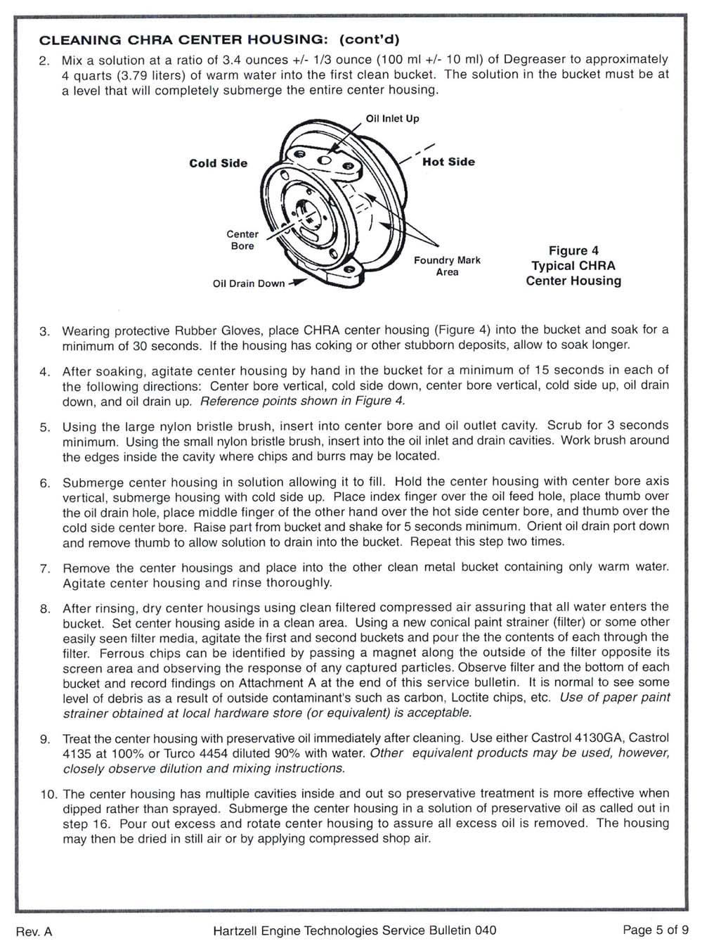
9 CLEANING CHRA CENTER HOUSING: (cont d) 2. Mix a solution at a ratio of 3.4 ounces +/- 1/3 ounce (100 ml +/- 10 ml) of Degreaser to approximately 4 quarts (3.79 liters) of warm water into the first clean bucket. The solution in the bucket must be at a level that will completely submerge the entire center housing. Figure 4 Typical CHRA Center Housing 3. Wearing protective Rubber Gloves, place CHRA center housing (Figure 4) into the bucket and soak for a minimum of 30 seconds. If the housing has coking or other stubborn deposits, allow to soak longer. 4. After soaking, agitate center housing by hand in the bucket for a minimum of 15 seconds in each of the following directions: Center bore vertical, cold side down, center bore vertical, cold side up, oil drain down, and oil drain up. Reference points shown in Figure Using the large nylon bristle brush, insert into center bore and oil outlet cavity. Scrub for 3 seconds minimum. Using the small nylon bristle brush, insert into the oil inlet and drain cavities. Work brush around the edges inside the cavity where chips and burrs may be located. 6. Submerge center housing in solution allowing it to fill. Hold the center housing with center bore axis vertical, submerge housing with cold side up. Place index finger over the oil feed hole, place thumb over the oil drain hole, place middle finger of the other hand over the hot side center bore, and thumb over the cold side center bore. Raise part from bucket and shake for 5 seconds minimum. Orient oil drain port down and remove thumb to allow solution to drain into the bucket. Repeat this step two times. 7. Remove the center housings and place into the other clean metal bucket containing only warm water. Agitate center housing and rinse thoroughly. 8. After rinsing, dry center housings using clean filtered compressed air assuring that all water enters the bucket. Set center housing aside in a clean area. Using a new conical paint strainer (filter) or some other easily seen filter media, agitate the first and second buckets and pour the the contents of each through the filter. Ferrous chips can be identified by passing a magnet along the outside of the filter opposite its screen area and observing the response of any captured particles. Observe filter and the bottom of each bucket and record findings on Attachment A at the end of this service bulletin. It is normal to see some level of debris as a result of outside contaminant's such as carbon, Loctite chips, etc. Use of paper paint strainer obtained at local hardware store (or equivalent) is acceptable. 9. Treat the center housing with preservative oil immediately after cleaning. Use either Castrol 4130GA, Castrol 4135 at 100% or Turco 4454 diluted 90% with water. Other equivalent products may be used, however, closely observe dilution and mixing instructions. 10. The center housing has multiple cavities inside and out so preservative treatment is more effective when dipped rather than sprayed. Submerge the center housing in a solution of preservative oil as called out in step 16. Pour out excess and rotate center housing to assure all excess oil is removed. The housing may then be dried in still air or by applying compressed shop air. Rev. A Hartzell Engine Technologies Service Bulletin 040 Page 5 of 9
10 REASSEMBLY: 1. Once the CHRA center housing has been cleaned, reassemble the turbocharger. Observe Chapter 2 General Cleaning instructions (pages & ) and General Inspection (pages & ) as required prior to starting reassembly. 2. Reassemble the turbocharger referring to the appropriate Reassembly section of Chapter 2 for your specific model designation. Be sure to return the housings to the proper orientation as noted if previously required by the instructions. REPAIRED TURBOCHARGER INSTALLATION: 1. Upon completion of the turbocharger reassembly, the appropriate paperwork must be made indicating that the turbocharger has been repaired. This paperwork must be included in the aircraft records. Once this is accomplished, prepare to re-install the turbocharger on the engine. If sent to a repair station, verify the turbocharger has the correct part number and serial number for your aircraft and that the proper paperwork was delivered with the unit. 2. Prior to installation of the turbocharger, flush the oil line from the turbo to the oil sump with clean engine oil. Utilizing the most current Service Manual or Service Instructions of the applicable engine or airframe manufacturer, perform an engine oil and filter change. Drain the engine oil completely through a porous white cloth to examine for metal particles and ferrous chips. Remove the engine oil filter and completely drain contents through a porous white cloth and examine for metal particles and ferrous chips. 3. Cut open the oil filter and examine the pleats for metal particles and ferrous chips. If a magnetic oil plug is installed, examine it for metal particles and ferrous chips. 4. If metal particles and ferrous chips are present, consult the engine manufacturer s recommendations for engine oil contamination and/or oil system flushing prior to completing engine oil and filter change. If no metal particles or ferrous chips are found or upon completion of the above actions, complete the engine oil and filter change per engine manufacturer s service instructions. 5. Utilizing the applicable aircraft and/or engine manufacturer s maintenance manuals or service instructions of the latest revision, re-install the turbocharger assembly and proceed to Return to Service below. RETURN TO SERVICE: 1. Once the turbocharger has been properly re-installed, the aircraft will be ready for return to service. 2. Refer to Kelly Aerospace Energy Systems Service Bulletin 23 and perform the recommended turbocharger operational tests. This consists of turbocharger pre-lubrication, ground running tests, and and operational flight test. Make sure no air, exhaust, or oil leaks are present. Service Bulletin may be viewed or downloaded online via 3. Utilizing the applicable aircraft and engine manufacturer s maintenance manuals of the latest revision, install any portion of the aircraft removed to gain access. 4. Upon successful completion of this service bulletin per the applicable compliance time listed, make an appropriate log book entry. (If repair accomplished, be sure to include the turbo repair records). Page 6 of 9 Hartzell Engine Technologies Service Bulletin 040 Rev. A
11 PARTS REQUIRED: Consult the latest revision of the KAES Turbocharger Overhaul & Maintenance manual (P/N ) Illustrated Parts Catalog as required to comply with this service bulletin. Incidental parts may be required for the turbocharger installation. These parts must be obtained from the applicable engine or airframe manufacturer. PARTS IN INVENTORY: Affected unused stock in customers hands must be returned through place of purchase. See the Appendix I for Commercial Assistance. Rev. A Hartzell Engine Technologies Service Bulletin 040 Page 7 of 9
12 TABLE 2 - Affected Turbocharger Reference Table Turbocharger Ass y Engine Ass y Aircraft (not limited to) Turbocharger Model (646677) TSIO-520-BE Piper Malibu Conversion TA ( ) TSIO-360-MB, SB TIO-540-AK1A Mooney Encore TIO-540-AK1AT TA ( ) L/TSIO-360-RB Piper, Seneca V TA (46C19839) TIO-540-AE2A Piper PA46-350P, Malibu Mirage TA (46C22924) (C ) (C ) TIO-540-AK1A Cessna, T182 TAO411 TSIO-360-H Cessna T337 TAO L3C5D Cessna T182, TR182 TAO ( ) TSIO-520-T Cessna T188C TAO L/TO-360-E1A6D Piper PA44-180T TAO (46C19836) TIO-540-AG1A TIO-540-AF1A TIO-540-AF1B TIO-540-AH1A Commander 114TC Mooney M20M (TLS) Mooney M20M (TLS Bravo) Piper PA32-301T Saratoga TAO (LW-13310) TIO-541-E1D4 TIO-541-E1C4 Beech A56TC, A60, Duke T (LW-10191) TIGO-541-E Piper PA31P T18A ( ) GTSIO-520-F, GTSIO-520-K Twin Commander 685 T18A ( ) GTSIO-520-D Cessna 421, 421A THO ( ) GTSIO-520-H Cessna 421B TEO659 NOTE: The reference Table 2 should be used as a guide only for turbocharged aircraft. Not every aircraft or engine combination is listed and not every STC or other field application is included. This list is provided to help identify which aircraft may be affected by this service bulletin. Page 8 of 9 Hartzell Engine Technologies Service Bulletin 040 Rev. A
13 APPENDIX I COMMERCIAL ASSISTANCE: In addition to warranty coverage provided by the KAES or HET Limited Warranty, HET will provide additional commercial assistance to comply with SB040 under the terms outlined in this Appendix. Commercial Assistance the following will be provided with the submission of a completed PPCR (Attachment A, Sections I and II only) along with copies of invoices showing breakdown of labor charges and log book entries. This will serve as a claim form when received by HET warranty department. If the unit is not sent to HET for disassembly and cleaning, a completed PPCR (Attachment A, with all Sections completed) along with copies of invoices showing breakdown of labor charges and log book entries must be submitted. This will serve as a claim form when received by HET warranty department. Identification up to 1 hour labor (up to $75 maximum) Removal and Installation, if necessary up to 4 hours labor (up to $300 maximum) Disassembly and Cleaning Reassembly Within North America - for units sent to HET there will be no charge for this work and unit will be returned shipping pre-paid by the same method as received. Outside North America for units sent to HET there will be no charge for this work and will be returned shipping pre-paid, less any applicable duties, by the same method as received. As an alternative, HET will provide a labor allowance of 3 hours labor (up to US $225 maximum) for units sent to nearest of the following facilities: PLANE SUPPORT (AEROTEST PTY LTD) Sunshine Coast Airport Mudjimba Qld 4564 Australia ABN ian@planesupport.com Ph: Fax: VORTEX MOTORS Aj. Olavo Fontoura 484 San Paulo Brazil Tel: Fax: ctm@vortexmotores.com.br vortex@vortexmotores.com.br ROEDER PRAEZISION Am Flugplatz Egelsbach 63329, Germany Tel: Fax: URL: SHIPPING INFORMATION: (when returning to HET) Turbocharger must be securely packed and packaged so no oil will seep into the shipping container. A copy of Attachment A must have Customer Information and Product or Component Information sections filled out completely and included inside the shipping container. The turbocharger must be received assembled and undamaged to qualify for repair. Address package to Hartzell Engine Technologies, LLC, Warranty Department, 2900 Selma Highway, Montgomery, AL 36108, USA. Also mark WARRANTY DEPT clearly on the outside of the shipping container. HET will only pay for return shipping by the same method as received. (next day, ground, etc.) CONTACT INFORMATION: All communications regarding this service bulletin, must be placed either through Hartzell Engine Technologies Technical Support at (888) or via Fax (334) For the Warranty department, (334) Written communications must be placed through Hartzell Engine Technologies Technical Support, 2900 Selma Highway, Montgomery, AL 36108, USA. If communication is desired, go to our website: and select contact and follow the instructions. Rev. A Hartzell Engine Technologies Service Bulletin 040 Page 9 of 9
14 ATTACHMENT A SECTION I: Customer information (Completed by End User) PPCR Publication Product Condition Report (To validate warranty or commercial assistance, all information MUST be filled out.) Name: Date of Report: Tel: Company Name: Address: Aircraft Mfg/: Time in Service: Model: S/N: Engine (as may be applicable) SECTION II: Product or Component Information (Completed by End User) Nomenclature: TURBOCHARGER Part Number: Serial Number: Batch/Date Code: Part Time in Service: SECTION III: Compliance Information: (Completed by Repair Facility) Compliance with SB-040: YES Debris found: YES NO If yes, please describe quantity and size below: Eligibility: To be eligible for any commercial assistance, this form must be completed as instructed above and will serve as a claim form. NO reimbursement will be made without completing this form. For further information contact Hartzell Engine Technologies, LLC at: 2900 Selma Highway, Montgomery, AL, USA or FAX to HET Customer Service, The complete service bulletin is available to you online via our website at
15
16
17
18
19
20
21
22
23
24
25
26
27 TELEDYNE CONTINENTAL AIRCRAFT ENGINE SERVICE BULLETIN Contains Important Information Pertaining to Your Aircraft Engine. Compliance Will Enhance Safety Category 3 SB10-8 Technical Portions FAA Approved SUBJECT: Hartzell Engine Technologies Service Bulletin 040 Turbocharger CHRA contamination PURPOSE: To notify of inspection of turbocharger center housing rotating assemblies COMPLIANCE: 1. For turbochargers having between 0 and 10 hours time in service (TIS) including field overhauls, a. Turbochargers must be inspected before further flight 2. For turbochargers having between 10 and 50 hours time in service (TIS) including field overhauls: a. Turbochargers must be inspected within the next ten (10) hours time in service 3. For turbochargers operated beyond 50 hours time in service, including field overhauled: a. No action is required MODELS AFFECTED: TSIO-360-MB, SB; L/TSIO-360-RB; TSIO-520-BE; TSIO-520-T; TSIO- 550-A, B, C, E, G, K; TSIOF-550-K; GTSIO-520-D, F, H, K; General Hartzell Engine Technologies LLC (HET) has become aware of a condition affecting certain turbocharger center housing rotating assemblies (CHRA) where debris may not have been removed after the machining operation. The HET Service Bulletin is being issued to mandate the cleaning of CHRA center housing of turbochargers. Teledyne Continental Motors recommends compliance with this service bulletin as shown above. Non-compliance with this bulletin may result in seizure of the shaft and/or turbine wheel head separation. This condition may also lead to a loss of engine oil. Either condition may lead to a complete loss of turbocharger function without warning as well as a partial or complete loss of engine power. Warranty Normal warranty policies will apply to the replacement of any TCM supplied turbochargers. Engines within warranty coverage that require turbocharger replacement should file a warranty claim through the TCM distributor furnishing the replacement turbocharger. If a replacement turbocharger is purchased through a Hartzell Engine Technologies distributor, the warranty claim for the replacement turbocharger must be filed to Hartzell Engine Technologies, through the supplying distributor. ISSUED REVISED PAGE NO REVISION TM MO DAY YEAR MO DAY YEAR CONTINENTAL MOTORS 1 of A Teledyne Technologies Company P.O. BOX 90 MOBILE ALABAMA SB10-8 Original
28 All questions concerning the inspections and replacement required by this bulletin shall be directed to: Hartzell Engine Technologies 2900 Selma Highway Montgomery, AL ISSUED REVISED PAGE NO REVISION TM MO DAY YEAR MO DAY YEAR CONTINENTAL MOTORS 2 of A Teledyne Technologies Company P.O. BOX 90 MOBILE ALABAMA SB10-8 Original
29 2900 Selma Highway Montgomery, AL USA Tel: Fax: Service Bulletin Compliance is Considered Mandatory Bulletin No. 040 Issue Date: Nov. 9, 2010 TURBOCHARGER CHRA CONTAMINATION INTRODUCTION: Hartzell Engine Technologies LLC (HET) has become aware of a condition affecting certain turbocharger center housing rotating assemblies (CHRA) where debris may not have been removed after the machining operation. The debris could enter the normal oil flow to the turbine wheel shaft assembly resulting in seizure of the shaft and/or turbine wheel head separation. This condition may also lead to a loss of engine oil. Either condition may lead to a complete loss of turbocharger function without warning as well as a partial or complete loss of engine power. Since this debris is expected to enter the oil stream quickly, the effects listed above can also occur quickly. The instructions herein identify the two manufacturing sources for the CHRA center housings of which only one is affected. This Service Bulletin is being issued to mandate the cleaning of CHRA center housing of turbochargers according to Table 1 below. COMPLIANCE: For turbochargers having between 0 and 10 hours time in service (TIS) including field overhauls, before further flight perform the IDENTIFICATION section of this procedure. If the CHRA center housing is affected, remove the turbocharger in order to proceed to the DISASSEMBLY and CLEANING sections and perform the required actions. For turbochargers having between 10 and 50 hours time in service (TIS) including field overhauls: Within the next ten (10) hours time in service, perform the IDENTIFICATION section of this procedure. If the CHRA center housing is affected, remove the turbocharger in order to proceed to the DISASSEMBLY and CLEANING sections and perform the required actions. For turbochargers operated beyond 50 hours time in service, including field overhauled: No action is required. EFFECTIVITY: Any aircraft or engine utilizing new (-0000 series) or rebuilt (-9000 series), turbochargers, manufactured before serial number H-NJL00003 (new) or H-NJR00002 (rebuilt) with the compliance times above. See Table 1a & 1b for applicable part numbers Applications may include but are not limited to those specified in Table 2. If you have any questions concerning the instructions in this service bulletin, please contact Hartzell Engine Technologies Technical Support at Questions concerning aircraft service or operation must be forwarded to the applicable manufacturer of that product. New Hartzell Engine Technologies Service Bulletin 040 Page 1 of 9
30 EFFECTIVITY: (cont d) Table 1a - Applicable KAES Part Numbers (Turbocharger) Table 1b - Applicable Original Equipment (OE) Part Numbers (Turbochargers) The turbocharger part numbers above or below may appear on the data tag C C C22924 C C LW LW LW IDENTIFICATION WARNING: THIS PROCEDURE MUST BE PERFORMED BY COMPETENT AND QUALIFIED PERSONNEL FAMILIAR WITH ENGINE AND AIRFRAME MAINTENANCE THAT IS SPECIFIC TO THE TURBOCHARGING SYSTEM. FAILURE TO DO SO MAY RESULT IN ECONOMIC LOSS, EQUIPMENT DAMAGE, AND/OR PHYSICAL INJURY. CAUTION: DO NOT DEPEND ON THIS SERVICE BULLETIN FOR GAINING ACCESS TO THE AIRCRAFT OR ENGINE. THIS WILL REQUIRE THAT YOU USE THE APPLICABLE MANUFACTURER S MAINTENANCE MANUALS OR SERVICE INSTRUCTIONS. IN ADDITION, ANY PREFLIGHT OR IN FLIGHT OPERATIONAL CHECKS REQUIRE USE OF THE APPROPRIATE AFM OR POH. 1. Access the aircraft turbocharger(s) in accordance with the instructions in the aircraft maintenance manual. Some aircraft engines have two turbochargers, so check both. (Do not rely on the aircraft or engine paperwork alone to identify the turbocharger part number.) 2. Refer to Table I to determine if the turbocharger being inspected is an affected part number. Observe the part number found on the data plate. If the affected part number does not appear, go to the Return to Service section step 3 & 4. If an affected part number does appear, continue with step 3. (See Figure 1 for typical turbocharger installation.) 3. Using Figures 2, 3, and 4, identify the foundry mark located on the CHRA center housing as shown. Those with a circled JT are not affected and may proceed to the Return to Service section step 3 & 4. If a slanted A appears, continue with the DISASSEMBLY and CLEANING sections. NOTE: For engine or aircraft models, reference Table 2. It should be used for identifying turbocharged aircraft as a guide only. Not every aircraft or engine combination is listed and not every STC or other field application is included. This list is provided to help identify which aircraft may be affected by this service bulletin. Page 2 of 9 Hartzell Engine Technologies Service Bulletin 040 New


31 IDENTIFICATION (cont d) Typical Turbocharger C H R A D a t a T a g i n t h i s A r e a Figure 1 - Typical Turbo Installation CHRA CENTER HOUSING I.D. Suspect Good Figure 2 - Foundry Mark Slanted A Figure 3 - Foundry Mark JT Foundry Mark May Also Be An Indented Slanted A Suspect 4. If it has been determined that the CHRA center housing is affected per Table 1 and IDENTIFICATION section above, the turbocharger must be removed and disassembled to isolate the CHRA center housing. 5. Utilizing the most current Service Manual or Service Instructions of the applicable engine or airframe manufacturer, remove the turbocharger from the engine. To avoid the possibility of debris entering the turbocharger system connections, cap all open lines and ducts. New Hartzell Engine Technologies Service Bulletin 040 Page 3 of 9
32 DISASSEMBLY AND CLEANING: WARNING: TO PROPERLY INSPECT, DISASSEMBLE, ASSEMBLE, AND TEST THE TURBO- CHARGER, THE MOST CURRENT REVISION OF THE KELLY AEROSPACE ENERGY SYSTEMS (KAES) OVERHAUL AND MAINTENANCE MANUAL P/N MUST BE USED. THE PROCEDURES THEREIN MUST BE FOLLOWED PRECISELY. FAILURE TO DO SO MAY RESULT IN ECONOMIC LOSS, EQUIPMENT DAMAGE, AND/OR PHYSICAL INJURY. NOTE: It is required, that all turbochargers be removed from the engine and sent to HET or to a properly FAA certificated repair station (or the foreign equivalent) experienced in servicing turbocharger systems for this disassembly and cleaning. Removal must be in accordance with the applicable aircraft and/or engine manufacturer s maintenance manuals or service instructions. Do not return turbo with fittings, oil reservoir,or other engine or airframe parts. 1. Prepare a clean and suitable work area for the removed turbocharger. Utilizing the KAES Overhaul and Maintenance Manual P/N , disassemble the turbocharger completely and isolate the CHRA. Because of the many different models of turbochargers affected and the differences in disassembly, refer to Table 2 to determine model. (For example, P/N turbocharger would be a model T1879.) It will be necessary to use this model number and select the instructions in Chapter 2 of the Overhaul manual P/N Observe Special Tools (pages & ) for tools required for disassembly or reassembly. 2. Using a soft bristle brush (paint brush style), thoroughly clean the outside of the CHRA prior to disassembly. Blow dry with clean oil free shop air. This avoids outside contaminates from the CHRA affecting the CHRA center housing cleaning process below. 3. Turn to the disassembly section of Chapter 2 and follow the appropriate steps for the specific model turbocharger and disassemble enough to isolate the CHRA center housing from all of it s internal component parts (bearings, seals, wheels, etc.). Be sure to note the orientation of the housings to one another if required by the instructions. 4. Once the CHRA center housing has been isolated, cover the remaining disassembled turbocharger parts to avoid contamination. Proceed to CLEANING CHRA CENTER HOUSING below. CLEANING CHRA CENTER HOUSING: WARNING: CLEANING MUST BE PERFORMED IN A WELL VENTILATED AREA. HAND AND EYE PROTECTION IS REQUIRED. USE OF HAZARDOUS CHEMICALS REQUIRES A FULL UNDERSTANDING OF EFFECTS OF HANDLING THESE PRODUCTS. FOLLOW THE CHEMICAL MANUFACTURER S INSTRUCTIONS FOR USE AND DISPOSAL. FAILURE TO DO SO MAY RESULT IN PHYSICAL INJURY OR DEATH. 1. Prepare for cleaning the CHRA center housing. Obtain the following materials locally: Two clean solvent and corrosive resistant metal buckets 1.5 gal. minimum (5.7 liter). A Large Flexible Nylon Bristle Brush (.50 inch diameter) min.1 in. long brush. SHB P/N 1303 or equivalent* A Small Flexible Nylon Bristle Brush (.25 inch diameter) min.1 in. long brush. SHB P/N 1307 or equivalent* Super Strength Greased Lightning Multi-Purpose Degreaser or equivalent, sufficient amount. One graduated beaker 150 ml (five ounce). Oil Preservative, Castrol 4130GA, 4135 at 100% or Turco 4454 diluted 90% with water (or equivalent). Solvent resistant rubber gloves. * Solo Horton Brushes, Inc, P.O. Box 478, Winsted, CT ( Page 4 of 9 Hartzell Engine Technologies Service Bulletin 040 New
33 CLEANING CHRA CENTER HOUSING: (cont d) 2. Mix a solution at a ratio of 3.4 ounces +/- 1/3 ounce (100 ml +/- 10 ml) of Degreaser to approximately 4 quarts (3.79 liters) of warm water into the first clean bucket. The solution in the bucket must be at a level that will completely submerge the entire center housing. Figure 4 Typical CHRA Center Housing 3. Wearing protective Rubber Gloves, place CHRA center housing (Figure 4) into the bucket and soak for a minimum of 30 seconds. If the housing has coking or other stubborn deposits, allow to soak longer. 4. After soaking, agitate center housing by hand in the bucket for a minimum of 15 seconds in each of the following directions: Center bore vertical, cold side down, center bore vertical, cold side up, oil drain down, and oil drain up. Reference points shown in Figure Using the large nylon bristle brush, insert into center bore and oil outlet cavity. Scrub for 3 seconds minimum. Using the small nylon bristle brush, insert into the oil inlet and drain cavities. Work brush around the edges inside the cavity where chips and burrs may be located. 6. Submerge center housing in solution allowing it to fill. Hold the center housing with center bore axis vertical, submerge housing with cold side up. Place index finger over the oil feed hole, place thumb over the oil drain hole, place middle finger of the other hand over the hot side center bore, and thumb over the cold side center bore. Raise part from bucket and shake for 5 seconds minimum. Orient oil drain port down and remove thumb to allow solution to drain into the bucket. Repeat this step two times. 7. Remove the center housings and place into the other clean metal bucket containing only warm water. Agitate center housing and rinse thoroughly. 8. After rinsing, dry center housings using clean filtered compressed air assuring that all water enters the bucket. Set center housing aside in a clean area. Using a new conical paint strainer (filter) or some other easily seen filter media, agitate the first and second buckets and pour the the contents of each through the filter. Ferrous chips can be identified by passing a magnet along the outside of the filter opposite its screen area and observing the response of any captured particles. Observe filter and the bottom of each bucket and record findings on Attachment A at the end of this service bulletin. It is normal to see some level of debris as a result of outside contaminant's such as carbon, Loctite chips, etc. Use of paper paint strainer obtained at local hardware store (or equivalent) is acceptable. 9. Treat the center housing with preservative oil immediately after cleaning. Use either Castrol 4130GA, Castrol 4135 at 100% or Turco 4454 diluted 90% with water. Other equivalent products may be used, however, closely observe dilution and mixing instructions. 10. The center housing has multiple cavities inside and out so preservative treatment is more effective when dipped rather than sprayed. Submerge the center housing in a solution of preservative oil as called out in step 16. Pour out excess and rotate center housing to assure all excess oil is removed. The housing may then be dried in still air or by applying compressed shop air. New Hartzell Engine Technologies Service Bulletin 040 Page 5 of 9
34 REASSEMBLY: 1. Once the CHRA center housing has been cleaned, reassemble the turbocharger. Observe Chapter 2 General Cleaning instructions (pages & ) and General Inspection (pages & ) as required prior to starting reassembly. 2. Reassemble the turbocharger referring to the appropriate Reassembly section of Chapter 2 for your specific model designation. Be sure to return the housings to the proper orientation as noted if previously required by the instructions. REPAIRED TURBOCHARGER INSTALLATION: 1. Upon completion of the turbocharger reassembly, the appropriate paperwork must be made indicating that the turbocharger has been repaired. This paperwork must be included in the aircraft records. Once this is accomplished, prepare to re-install the turbocharger on the engine. If sent to a repair station, verify the turbocharger has the correct part number and serial number for your aircraft and that the proper paperwork was delivered with the unit. 2. Prior to installation of the turbocharger, flush the oil line from the turbo to the oil sump with clean engine oil. Utilizing the most current Service Manual or Service Instructions of the applicable engine or airframe manufacturer, perform an engine oil and filter change. Drain the engine oil completely through a porous white cloth to examine for metal particles and ferrous chips. Remove the engine oil filter and completely drain contents through a porous white cloth and examine for metal particles and ferrous chips. 3. Cut open the oil filter and examine the pleats for metal particles and ferrous chips. If a magnetic oil plug is installed, examine it for metal particles and ferrous chips. 4. If metal particles and ferrous chips are present, consult the engine manufacturer s recommendations for engine oil contamination and/or oil system flushing prior to completing engine oil and filter change. If no metal particles or ferrous chips are found or upon completion of the above actions, complete the engine oil and filter change per engine manufacturer s service instructions. 5. Utilizing the applicable aircraft and/or engine manufacturer s maintenance manuals or service instructions of the latest revision, re-install the turbocharger assembly and proceed to Return to Service below. RETURN TO SERVICE: 1. Once the turbocharger has been properly re-installed, the aircraft will be ready for return to service. 2. Refer to Kelly Aerospace Energy Systems Service Bulletin 23 and perform the recommended turbocharger operational tests. This consists of turbocharger pre-lubrication, ground running tests, and and operational flight test. Make sure no air, exhaust, or oil leaks are present. Service Bulletin may be viewed or downloaded online via 3. Utilizing the applicable aircraft and engine manufacturer s maintenance manuals of the latest revision, install any portion of the aircraft removed to gain access. 4. Upon successful completion of this service bulletin per the applicable compliance time listed, make an appropriate log book entry. (If repair accomplished, be sure to include the turbo repair records). Page 6 of 9 Hartzell Engine Technologies Service Bulletin 040 New
This Service Bulletin is being issued to mandate the cleaning of CHRA center housing of turbochargers according to Table 1 below.
 2900 Selma Highway Montgomery, AL 36108 USA Tel: 334-386-5400 Fax: 334-386-5450 Service Bulletin Compliance is Considered Mandatory Bulletin No. 040 Issue Date: Nov. 9, 2010 TURBOCHARGER CHRA CONTAMINATION
Alert Service Bulletin
 Alert Service Bulletin 2900 Selma Highway Montgomery, AL 36108 USA Tel: 334-386-5400 Fax: 334-386-5450 1. Planning Information A. Effectivity (1) All Hartzell Engine Technologies LLC (HET) turbochargers:
201F Fuel Pump Shaft Seal Leak
 2900 Selma Highway Montgomery, AL 36108 USA Tel: 334-386-5400 Fax: 334-386-5450 201F Fuel Pump Shaft Seal Leak 1. Planning Information A. Effectivity* (1) Hartzell Engine Technologies LLC (HET) 201F Series
ALERT SERVICE BULLETIN
 2900 Selma Highway Montgomery, AL 36108 USA Tel: 334-386-5400 Fax: 334-386-5450 ALERT SERVICE BULLETIN Alert Service Bulletin No. 074 1. Planning Information A. Effectivity (1) Aeroforce turbocharger center
Table 1: Alternator Models ES (CMI ), ALX-9524 (CMI ), ALX-9524R, & ALV-9610 Affected Serial Numbers
, ALX-9524 (CMI ), ALX-9524R, & ALV-9610 Affected Serial Numbers") 2900 Selma Highway Montgomery, AL 36108 USA Tel: 334-386-5400 Fax: 334-386-5450 Service Bulletin Alternator Inspection for Burrs in the Rotor Shaft Hex Key Socket 1. Planning Information A. Effectivity
2900 Selma Highway Montgomery, AL 36108 USA Tel: 334-386-5400 Fax: 334-386-5450 Service Bulletin Alternator Inspection for Burrs in the Rotor Shaft Hex Key Socket 1. Planning Information A. Effectivity
201F Fuel Pump Valve Assembly Leakage
 2900 Selma Highway Montgomery, AL 36108 USA Tel: 334-386-5400 Fax: 334-386-5450 201F Fuel Pump Valve Assembly Leakage 1. Planning Information A. Effectivity (1) Hartzell Engine Technologies LLC (HET) 201F
LYCOMING ENGINES AND TELEDYNE CONTINENTAL MOTORS
 Page 1 011-13-03 LYCOMING ENGINES AND TELEDYNE CONTINENTAL MOTORS (TYPE CERTIFICATE PREVIOUSLY HELD BY TEXTRON LYCOMING) AND TELEDYNE CONTINENTAL MOTORS (TCM) TURBOCHARGED RECIPROCATING ENGINES Amendment
SERVICE BULLETIN MANDATORY
 652 Oliver Street Williamsport, PA 17701 U.S.A. Tel. 570-323-6181 Fax. 570-327-7101 www.lycoming.com MANDATORY SERVICE BULLETIN DATE: January 10, 2011 Service Bulletin No. 594 Engineering Aspects are FAA
SUBJECT: Kelly Aerospace Energy Systems Service Bulletin 038 A ES TCM P/N Inspection of Slip Ring End Housings for Cracks
 TELEDYNE CONTINENTAL AIRCRAFT ENGINE SERVICE BULLETIN Contains Important Information Pertaining to Your Aircraft Engine. Compliance Will Enhance Safety Category 3 Technical Portions FAA Approved SUBJECT:
201F Fuel Pump Valve Housing Cap Screw Replacement
 Service Bulletin 2900 Selma Highway Montgomery, AL 36108 USA Tel: 334-386-5400 Fax: 334-386-5450 http://www.hartzell.aero 201F Fuel Pump Valve Housing Cap Screw Replacement 1. Planning Information A. Effectivity
The Subject Matter Of This Service Bulletin Is Incorporated In Whole Or In Part In An FAA Issued Airworthiness Directive
 TELEDYNE CONTINENTAL AIRCRAFT ENGINE MANDATORY SERVICE BULLETIN The Subject Matter Of This Service Bulletin Is Incorporated In Whole Or In Part In An FAA Issued Airworthiness Directive Category 1 MSB08-5
Service Information Letter
 Service Information Letter Open Rotor Circuit 9910591 Series Alternators Issue Date: December 20, 2006, Revision 1 Original Issue Date: November 29, 2006 INTRODUCTION: Kelly Aerospace Turbine Rotables
FOR THE MOST RECENT REVISION LEVEL OF THIS SERVICE BULLETIN.
 2900 Selma Highway Montgomery, AL 36108 USA Tel: 334-386-5400 Fax: 334-386-5450 SERVICE BULLETIN 1. Planning Information A. Effectivity (1) Plane-Power Jasco series alternators manufactured by Hartzell
Affected , RX, , and RX alternators in Service Station stock should be returned to Cessna.
 Single Engine Service Bulletin December 18, 2006 TITLE 60 AMPERE ALTERNATOR BRUSH REPLACEMENT EFFECTIVITY The following airplanes currently equipped with part number 9910591-11, 9910591-11RX, 9910591-12
COMPLIANCE: As required by Kelly Aerospace Service Bulletin 033 (Attached)
") TELEDYNE CONTINENTAL AIRCRAFT ENGINE CRITICAL SERVICE BULLETIN COMPLIANCE NECESSARY TO MAINTAIN SAFETY Category 2 CSB08-11 Technical Portions FAA Approved SUBJECT: Kelly Aerospace Power Systems Service
TELEDYNE CONTINENTAL AIRCRAFT ENGINE CRITICAL SERVICE BULLETIN COMPLIANCE NECESSARY TO MAINTAIN SAFETY Category 2 CSB08-11 Technical Portions FAA Approved SUBJECT: Kelly Aerospace Power Systems Service
Service Bulletin. Service Bulletin No. 064 Alternator Model ALV-9610 Series Through Bolt Inspection for Proper Torque
 2900 Selma Highway Montgomery, AL 36108 USA Tel: 334-386-5400 Fax: 334-386-5450 http://www.hartzell.aero Service Bulletin Alternator Model ALV-9610 Series Through Bolt Inspection for Proper Torque 1. Planning
Airworthiness Directive Schedule
 Airworthiness Directive Schedule Engines 28 June 2018 Notes: 1. This AD schedule is applicable to general equipment, components and parts installed on reciprocating engines. These ADs should be listed
REASON FOR REVISION: To clarify effectivity by including RAM P/N cross reference. INTRODUCTION:
 Service Bulletin Compliance is Considered Mandatory The technical content of this letter is FAA Approved Bulletin No. 030 Rev. A Issue Date: April 1, 2008 TURBOCHARGER EXHAUST FLANGE INSPECTION AND/OR
It has been determined that some airplanes may have a hose plug installed in the inflatable belt assembly hose end.
 Single Engine Service Bulletin November 19, 2007 TITLE AMSAFE INFLATABLE RESTRAINTS HOSE PLUG INSPECTION EFFECTIVITY Group A airplanes: The following airplanes were delivered from the factory equipped
This Service Bulletin is applicable only to airplanes equipped with placards that are written in English.
 Caravan Service Bulletin June 25, 2007 TITLE FUEL CAPACITY PLACARD REPLACEMENT EFFECTIVITY This Service Bulletin is applicable only to airplanes equipped with placards that are written in English. The
SUBJECT: Single Engine Service Bulletin SB Revision 1: Cosmetic Window Repair
 Revision Transmittal TO: Cessna Distributors, Single Engine Service Stations SUBJECT: Single Engine Service Bulletin Revision 1: Cosmetic Window Repair REASON FOR REVISION To revise the Compliance section
SERVICE LETTER. Hartzell Alert Service Bulletin No. 069, 200F, 201F, 202F Fuel Pump Leak Inspection And Diaphragm
 Single Engine SERVICE LETTER SEL-73-06 TITLE ENGINE FUEL AND CONTROL - TRANSMITTAL OF HARTZELL ALERT SERVICE BULLETIN NO. 069, 200F, 201F, 202F FUEL PUMP LEAK INSPECTION AND DIAPHRAGM REPLACEMENT EFFECTIVITY
FAA approval has been obtained on technical data in this publication that affects airplane type design.
 Caravan Service Bulletin July 20, 2010 TITLE RIGHT INBOARD FLAP BELL CRANK BEARING INSPECTION / REPLACEMENT EFFECTIVITY The airplanes that follow that have had part number S3952-5 Bearing(s) installed
Service Letter. Service Letter No. 060 CD Series Combustion Heater Fuel Shroud & Hardware Supersedure. 1. Planning Information
 2900 Selma Highway Montgomery, AL 36108 USA Tel: 334-386-5400 Fax: 334-386-5450 Service Letter CD Series Combustion Heater Fuel Shroud & Hardware Supersedure 1. Planning Information A. Effectivity (1)
Single Engine. Service Bulletin TITLE ELEVATOR TRIM TAB ACTUATOR ASSEMBLY INSPECTION EFFECTIVITY. Group A airplanes: Serial Numbers
 Single Engine Service Bulletin March 12, 2007 TITLE ELEVATOR TRIM TAB ACTUATOR ASSEMBLY INSPECTION EFFECTIVITY Group A airplanes: Model Serial Numbers 172R 17281353 thru 17281364, 17281369 thru 17281372
WARNING OPERATION OF AN ENGINE WITH A RESTRICTED OIL PASSAGE CAN CAUSE LOSS OF LUBRICATION AND SUBSEQUENT ENGINE FAILURE.
 TELEDYNE CONTINENTAL AIRCRAFT ENGINE CRITICAL SERVICE BULLETIN Compliance Necessary To Maintain Safety CATEGORY 2 CSB96-2 FAA APPROVED SUBJECT: PURPOSE: CRANKCASE OIL PASSAGE INSPECTION TCM has verified
NOTE: SB is a WAAS only supported build. If the autopilot is not WAAS equipped, the unlock card cannot be used at this time.
 Single Engine Service Bulletin July 22, 2011 TITLE GARMIN G1000 / FLINT AERO, INC AUXILIARY FUEL GALLON REMAINING ENABLEMENT EFFECTIVITY The following airplanes equipped with the Garmin G1000 Nav III Avionics
MANDATORY SERVICE BULLETIN
 CONTINENTAL MOTORS AIRCRAFT ENGINE MANDATORY SERVICE BULLETIN The Subject Matter Of The Service Bulletin Is Incorporated In Whole Or In Part In An FAA Issued Airworthiness Directive CATEGORY 1 TECHNICAL
Please replace any copy of SEB07-2 with the attached copy of SEB07-2 Revision 1 which is printed in its entirety.
 Revision Transmittal May 14, 2007 TO: Cessna Distributors, Single Engine Service Stations and CPC's SUBJECT: Single Engine Service Bulletin SEB07-2 Revision 1: Engine Mount Bracket Inspection. REASON FOR
CONTINENTAL AIRCRAFT ENGINE service bulletin
 CONTINENTAL AIRCRAFT ENGINE service bulletin M83-3 Technical Portions are FAA-DER Approved 14 February, 1983 TO: SUBJECT: MODELS AFFECTED: Aircraft Manufacturers, Distributors, Dealers, Engine Overhaul
CSB 665A TECHNICAL PORTIONS FAA APPROVED
 TELEDYNE CONTINENTAL IGNITION SYSTEM CRITICAL SERVICE BULLETIN Compliance Necessary To Maintain Safety CATEGORY 2 CSB 665A TECHNICAL PORTIONS FAA APPROVED SUBJECT: MAGNETO CAPACITOR P/N 10-400615 INSPECTION
Letter No. A-137 Issue Date: March 9, 2011
 Service Information Letter 2900 Selma Highway Montgomery, AL 36108 USA Tel: 334-386-5400 Fax: 334-386-5450 Letter No. A-137 Issue Date: March 9, 2011 INTRODUCTION: ES-6012-6 & ES-7024-11 & -14 Alternators
SERVICE BULLETIN. To prevent the wing fuel boost pump wiring from chafing on the wing structure and/or fuel tube assemblies.
 TITLE FUEL - WING FUEL BOOST PUMP WIRE ROUTING IMPROVEMENT EFFECTIVITY MODEL SERIAL NUMBERS 560-0001 thru -0538 REASON To prevent the wing fuel boost pump wiring from chafing on the wing structure and/or
Single Engine. Service Bulletin TITLE PILOT AND COPILOT SECONDARY SEAT STOP INSTALLATION
 Single Engine Service Bulletin May 14, 2007 TITLE PILOT AND COPILOT SECONDARY SEAT STOP INSTALLATION EFFECTIVITY Model Year Serial Numbers 170 1948 18000 thru 18729 170A 1949 thru 1951 18730 thru 19400
KELLY AEROSPACE POWER SYSTEMS
 Page 1 2008-08-17 KELLY AEROSPACE POWER SYSTEMS Amendment 39-15471 Docket No. FAA-2008-0314; Directorate Identifier 2008-NE-09-AD PREAMBLE Effective Date (a) This airworthiness directive (AD) becomes effective
SERVICE BULLETIN American Legend Aircraft Company considers compliance mandatory
 American Legend Aircraft Company 1810 Piper Lane Sulphur Springs, Texas 75482 903-885-7000 http://legend.aero SERVICE BULLETIN American Legend Aircraft Company considers compliance mandatory Notification
CRITICAL SERVICE BULLETIN Compliance Necessary to Maintain Safety
 TELEDYNE CONTINENTAL AIRCRAFT ENGINE CRITICAL SERVICE BULLETIN Compliance Necessary to Maintain Safety CATEGORY 2 CSB04-6 TECHNICAL PORTIONS FAA APPROVED SUBJECT: INSPECTION OF TSIO-550 AND TSIOL-550 ENGINES
[Docket No. FAA ; Directorate Identifier 2008-NE-09-AD; Amendment ; AD ]
![[Docket No. FAA ; Directorate Identifier 2008-NE-09-AD; Amendment ; AD ]](/thumbs/90/103888893.jpg "[Docket No. FAA ; Directorate Identifier 2008-NE-09-AD; Amendment ; AD ]") [Federal Register: April 21, 2008 (Volume 73, Number 77)] [Rules and Regulations] [Page 21222-21225] From the Federal Register Online via GPO Access [wais.access.gpo.gov] [DOCID:fr21ap08-3] DEPARTMENT
[Federal Register: April 21, 2008 (Volume 73, Number 77)] [Rules and Regulations] [Page 21222-21225] From the Federal Register Online via GPO Access [wais.access.gpo.gov] [DOCID:fr21ap08-3] DEPARTMENT
Letter A Planning Information. A. Effectivity
 1. Planning Information A. Effectivity (1) Hartzell Engine Technologies LLC (HET), formerly Kelly Aerospace Energy Systems, LLC (KAES), direct drive starter motor, models: ES646238-2, ES646238-3, ES646275-1,
PROPELLERS - PROPELLER SLIP RING MOUNTING PLATE INSPECTION AND REPAIR
 Beechcraft TITLE: PROPELLERS - PROPELLER SLIP RING MOUNTING PLATE INSPECTION AND REPAIR 1. Planning Information A. Effectivity (1) Airplanes Airplanes that have accomplished installation of Hartzell STC
ALERT SERVICE LETTER
 Citation TITLE ALERT SERVICE LETTER ASL525-32-21 LANDING GEAR - TRANSMITTAL OF GOODRICH 2-1559-32-4, MAIN LANDING GEAR - BRAKE ASSEMBLY - P/N S 2-1559-1 AND 2-1559-2 - CESSNA CITATION AIRCRAFT - INTRODUCTION
Single Engine. Service Bulletin TITLE ENGINE MOUNT BRACKET INSPECTION
 Single Engine Service Bulletin April 16, 2007 TITLE ENGINE MOUNT BRACKET INSPECTION EFFECTIVITY Model Year Serial Numbers 172 1956 thru 1959 28000 thru 29999 172 1956 thru 1959 36000 thru 36999 172 1956
ATTACHMENT. Orders for the required parts listed below must be placed by using this form only. Service Station/Company Code: Company Name:
 Single Engine ATTACHMENT CREW SEAT RECLINE MODIFICATION SB04-25-01 Revision 4 Orders for the required parts listed below must be placed by using this form only. NOTE: All web orders for these kits/parts
ATTACHMENT DAMAGE REPORT FORM. Page: 1 of Pages Includes this cover sheet Date: (month/day/year) This form is for the: Left Wing: Right Wing: Other:
 This form is for the: Left Wing: Right Wing: Other:") ATTACHMENT DAMAGE REPORT FORM TO: Cessna Aircraft Company Propeller Aircraft Customer Service/Dept 753 P.O. Box 7706 Wichita, Kansas 67277-7706 Phone Number: 316-517-5800 Fax Number: 316-942-9006 Page:
ATTACHMENT DAMAGE REPORT FORM TO: Cessna Aircraft Company Propeller Aircraft Customer Service/Dept 753 P.O. Box 7706 Wichita, Kansas 67277-7706 Phone Number: 316-517-5800 Fax Number: 316-942-9006 Page:
MODIFICATION KIT. Serial Numbers 300 (LC40-550FG) thru (LC42-550FG) thru (LC41-550FG) thru
 thru (LC42-550FG) thru (LC41-550FG) thru") Single Engine MODIFICATION KIT MK400-71-01 TITLE ENGINE OIL COOLER WINTERIZATION MODIFICATION EFFECTIVITY Model Serial Numbers 300 (LC40-550FG) 40004 thru 40079 350 (LC42-550FG) 42001 thru 421018 400 (LC41-550FG)
Single Engine MODIFICATION KIT MK400-71-01 TITLE ENGINE OIL COOLER WINTERIZATION MODIFICATION EFFECTIVITY Model Serial Numbers 300 (LC40-550FG) 40004 thru 40079 350 (LC42-550FG) 42001 thru 421018 400 (LC41-550FG)
SERVICE BULLETIN MANDATORY. SB , Rev Planning Information
 SERVICE BULLETIN TITLE: STABILIZERS - INSPECTION/REPLACEMENT OF ELEVATOR BALANCE WEIGHT ASSEMBLIES SYNOPSIS OF CHANGE This Service Bulletin has been revised to add a balance weight inspection every 100
Revision Transmittal Sheet
 2 APPROVED WHITE IN LEARJET 31 RT 31-32-24 Revision Transmittal Sheet This page transmits Revision 1 to No. 31-32-24, Main Landing Gear Torque Link Replacement. Rework: No rework is required for aircraft
SERVICE BULLETIN. Citation CIB TITLE FUEL - FIREWALL SHUTOFF VALVE GROUND IMPROVEMENT
 TITLE FUEL - FIREWALL SHUTOFF VALVE GROUND IMPROVEMENT EFFECTIVITY MODEL SERIAL NUMBERS 525 (CJ1+) -0680, -0685 thru -0799 525A (CJ2+) -0417, -0439 thru -0524 525B (CJ3) -0263, -0294 thru -0414 REASON
Contains Important Information Pertaining to Your Aircraft Engine Compliance Will Enhance Safety
 CONTINENTAL MOTORS AIRCRAFT ENGINE SERVICE ULLETIN Contains Important Information Pertaining to Your Aircraft Engine Compliance Will Enhance Safety Category 3 S09-4 Supersedes S09-4A TECHNICAL PORTIONS
SERVICE LETTER. Single Engine SEL TITLE LANDING GEAR - DRAG LINK REPLACEMENT
 SERVICE LETTER TITLE LANDING GEAR - DRAG LINK REPLACEMENT EFFECTIVITY Group A Airplanes: The following airplane serial numbers were delivered with a suspect 1243600-1 Drag Link Assembly: MODEL SERIAL NUMBERS
SERVICE BULLETIN. COMPLIANCE MANDATORY. This service bulletin must be accomplished at the next 100-hour or 12-month (annual-type) inspection.
 inspection.") TITLE EQUIPMENT/FURNISHINGS - SEAT BELT BRACKET INSPECTION EFFECTIVITY MODEL SERIAL NUMBERS 120 8000 thru 15075 140 8000 thru 15075 REASON Cessna Aircraft Company wishes to update the seat belt bracket
TITLE EQUIPMENT/FURNISHINGS - SEAT BELT BRACKET INSPECTION EFFECTIVITY MODEL SERIAL NUMBERS 120 8000 thru 15075 140 8000 thru 15075 REASON Cessna Aircraft Company wishes to update the seat belt bracket
Instructions for Continued Airworthiness
 Forced Aeromotive Technologies Instructions for Continued Airworthiness Supercharged IO-550-N Engines Installed On NOTICE This document must be referenced on Block 8 of FAA form 337 and added to the aircraft
SERVICE LETTER TITLE EXHAUST - TRANSMITTAL OF LYCOMING SERVICE BULLETIN NO 627C, EXHAUST SYSTEM INSPECTION SERIAL NUMBERS
 Single Engine MANDATORY SERVICE LETTER SEL-78-03 TITLE EXHAUST - TRANSMITTAL OF LYCOMING SERVICE BULLETIN NO 627C, EXHAUST SYSTEM INSPECTION EFFECTIVITY REASON MODEL T206H SERIAL NUMBERS T20608001 and
SERVICE BULLETIN REVISION TRANSMITTAL
 REVISION TRANSMITTAL This sheet transmits Revision 1 to, which: A. Rearranges the sub-steps in Step 5 for better flow. NOTE: There are no technical changes in Step 5. B. Adds Steps 6 thru 9 to the Accomplishment
PA Archer 28-E13; thru PA Archer II thru ; ; ; thru
 Piper Aircraft, Inc. 2926 Piper Drive Vero Beach, Florida, U.S.A. 32960 SERVICE NO. 1244A BULLETIN PIPER CONSIDERS COMPLIANCE MANDATORY Date: April 1, 2013 (S) (M) Service Bulletin (SB) 1244A supersedes
SERVICE BULLETIN. To prevent the wing fuel boost pump wiring from chafing on the wing structure and/or fuel tube assemblies.
 TITLE FUEL - WING FUEL BOOST PUMP WIRE ROUTING IMPROVEMENT EFFECTIVITY MODEL UNIT NUMBERS 500/501-0001 thru -0689 REASON To prevent the wing fuel boost pump wiring from chafing on the wing structure and/or
BULLETIN. Piper Aircraft, Inc Piper Drive Vero Beach, FL, U.S.A Date: October 29, 2015 (S) (M)
 (M)") Piper Aircraft, Inc. 2926 Piper Drive Vero Beach, FL, U.S.A. 32960 SERVICE NO. 1244B BULLETIN PIPER CONSIDERS COMPLIANCE MANDATORY Date: October 29, 2015 (S) (M) Service Bulletin (SB) 1244B supersedes
Piper Aircraft, Inc. 2926 Piper Drive Vero Beach, FL, U.S.A. 32960 SERVICE NO. 1244B BULLETIN PIPER CONSIDERS COMPLIANCE MANDATORY Date: October 29, 2015 (S) (M) Service Bulletin (SB) 1244B supersedes
SERVICE BULLETIN. The equivalent of this service bulletin has been incorporated on production airplanes and On.
 TITLE ICE AND RAIN PROTECTION - WING ANTI-ICE SYSTEM IMPROVEMENT EFFECTIVITY MODEL SERIAL NUMBERS 525B -0002 thru -0012 The equivalent of this service bulletin has been incorporated on production airplanes
Cessna Distributors and Single Engine Authorized Service Facilities and CPC's
 Revision Transmittal June 11, 2015 TO: Cessna Distributors and Single Engine Authorized Service Facilities and CPC's SUBJECT: Single Engine Service Bulletin, Pilot and Copilot Secondary Seat Stop Installation.
SERVICE BULLETIN. Beech ATA CODE PLACARDS AND MARKINGS - INSTALLATION OF FUEL SELECTOR PLACARD
 MANDATORY Beech ATA CODE 11-30 TITLE: PLACARDS AND MARKINGS - INSTALLATION OF FUEL SELECTOR PLACARD SYNOPSIS OF CHANGE This Service Bulletin has been revised and is produced in the new Raytheon Aircraft
Airworthiness Directive
 Airworthiness Directive Federal Register Information Header Information DEPARTMENT OF TRANSPORTATION Federal Aviation Administration 14 CFR Part 39 [62 FR 40262 NO. 144 07/28/97] [Docket No. 97-ANE-26-AD;
Single Engine Service Bulletin SEB08-4 Revision 1, Unision Industries SLICK 4200/4300/6200/6300 Magnetos Inspection.
 Revision Transmittal April 27, 2009 TO: Cessna Distributors, Single Engine Service Stations and CPC's SUBJECT: Single Engine Service Bulletin SEB08-4 Revision 1, Unision Industries SLICK 4200/4300/6200/6300
September 8, Cessna Distributors, Authorized Service Facilities, CPC's, CSTARS, ASR's, and affected Owners of Record
 Service Newsletter September 8, 2011 SNL11-23 TITLE P&WC PROPELLER-SHAFT OIL SEAL MODIFICATION TO Cessna Distributors, Authorized Service Facilities, CPC's, CSTARS, ASR's, and affected Owners of Record
SERVICE BULLETIN FLIGHT CONTROLS - RUDDERVATOR DIFFERENTIAL TAIL CONTROL ROD ASSEMBLY INSPECTION/MODIFICATION
 Beech ATA Code 27-20 TITLE: FLIGHT CONTROLS - RUDDERVATOR DIFFERENTIAL TAIL CONTROL ROD ASSEMBLY INSPECTION/MODIFICATION SYNOPSIS OF CHANGE This Service Bulletin has been revised and is produced in the
The New Piper Aircraft, Inc Piper Drive Vero Beach, Florida, U.S.A
 1022 The New Piper Aircraft, Inc. 2926 Piper Drive Vero Beach, Florida, U.S.A. 32960 DATE: September 22, 1998 (S/M) S U B J E C T : MODELS AFFECTED: Inspection of Induction Air Filter and D i s t r i b
SERVICE INSTRUCTION. ISSUED REVISED PAGE NO. REVISION MO DAY YEAR MO DAY YEAR 1 of 8 BB
 652 Oliver Street Williamsport, PA. 17701 U.S.A. Telephone +1 (800) 258-3279 U.S. and Canada (Toll Free) Telephone +1 (570) 323-6181 (Direct) Facsimile +1 (570) 327-7101 Email Technicalsupport@lycoming.com
DEPARTMENT OF TRANSPORTATION
 DEPARTMENT OF TRANSPORTATION Federal Aviation Administration 14 CFR Part 39 [62 FR 40262 No. 144; 07/28/97][SN] [Docket No. 97-ANE-26-AD; Amendment 39-10085; AD 97-15-11] RIN 2120-AA64 Avco Lycoming /
SERVICE LETTER SERIAL NUMBERS. 550/ thru -0505, thru -0733, thru -0969
 TITLE FUSELAGE - DORSAL FIN VANE INSPECTION EFFECTIVITY MODEL SERIAL NUMBERS 550/551-0002 thru -0505, -0550 thru -0733, -0801 thru -0969 REASON The equivalent of this service letter has been incorporated
To announce the issuance of Piper Service Bulletin 1157A
 TELEDYNE CONTINENTAL AIRCRAFT ENGINE SERVICE BULLETIN Compliance Will Enhance Safety SUBJECT: PIPER SERVICE BULLETIN 1157A Category 3 SB05-11 Technical Portions FAA Approved PURPOSE: COMPLIANCE: MODELS
SERVICE LETTER REVISION TRANSMITTAL
 REVISION TRANSMITTAL TO: Cessna Distributors, Multi-Engine Authorized Service Facilities, and CPC's SUBJECT: Multi-Engine Service Letter Revision 1: Hydraulic Power Pack Inspection REASON To add a coarse-threaded
SERVICE BULLETIN REVISION TRANSMITTAL
 REVISION TRANSMITTAL This sheet transmits Revision 1 to, which: A. Adds HDWR kit to the MATERIAL INFORMATION section. NOTE: This revision replaces the original issue of in its entirety. REVISION COMPLIANCE
SERVICE BULLETIN. NO.: 0713 Revision C. All Garmin Aviation Service Centers and Aircraft OEM Service Centers DATE: 29 May 2007
 SERVICE BULLETIN NO.: 0713 Revision C TO: All Garmin Aviation Service Centers and Aircraft OEM Service Centers DATE: 29 May 2007 SUBJECT: GSM 85 Inspection Procedure REVISION B: Revision C changes some
SID SERVICE INFORMATION DIRECTIVE Compliance Will Enhance Safety, Maintenance or Economy of Operation TELEDYNE CONTINENTAL AIRCRAFT ENGINE
 TELEDYNE CONTINENTAL AIRCRAFT ENGINE SERVICE INFORMATION DIRECTIVE Compliance Will Enhance Safety, Maintenance or Economy of Operation CATEGORY 4 Technical Portions FAA Approved SUBJECT: PURPOSE: COMPLIANCE:
SERVICE BULLETIN THIS BULLETIN IS FAA APPROVED FOR ENGINEERING DESIGN
 MOONEY AIRPLANE COMPANY, INC. SERVICE BULLETIN Louis Schreiner Field Kerrville, Texas 78028 DATE: October 30, 2003 THIS BULLETIN IS FAA APPROVED FOR ENGINEERING DESIGN SERVICE BULLETIN M20-282 DATE: October
Service Information Letter
 Service Information Letter The technical content of this letter is FAA Approved Letter No. A-110B Issue Date: Dec. 20, 2004 RECOMMENDED SERVICE/INSPECTION FOR MODEL 91E93-1 & 91E92-1 HEATER FUEL PUMP REASON
(b) This AD supersedes AD R1, Amendment
 This AD supersedes AD R1, Amendment") 2011-06-10 Piper Aircraft, Inc. (Type Certificate Previously Held by The New Piper Aircraft, Inc.):. Amendment 39-16635; Docket No. FAA-2010-1295; Directorate Identifier 2010-CE-060-AD. Effective Date
2011-06-10 Piper Aircraft, Inc. (Type Certificate Previously Held by The New Piper Aircraft, Inc.):. Amendment 39-16635; Docket No. FAA-2010-1295; Directorate Identifier 2010-CE-060-AD. Effective Date
SERVICE BULLETIN REVISION
 Revision 1 REVISION TRANSMITTAL SHEET This sheet transmits Revision 1 to. A. Adds Sheet 4 to Figure 1. B. Adds instructions to make the cutouts in the stiffener on the upper engine cowl larger. NOTE: This
SERVICE LETTER. SERIAL NUMBERS 210 & T thru P thru P
 TITLE SERVICE LETTER WINGS - LOWER MAIN SPAR CAP INSPECTION EFFECTIVITY REASON MODEL SERIAL NUMBERS 210 & T210 21058819 thru 21065009 P210 P2100001 thru P2100874 Reports have been received of cracks found
SERVICE BULLETIN REVISION
 Revision 1 REVISION TRANSMITTAL SHEET This sheet transmits Revision 1 to, which: A. Adds a Note to the EFFECTIVITY section and Step 1 to the ACCOMPLISHMENT INSTRUCTIONS section to include a reference to
SERVICE BULLETIN FUEL - MODIFICATION OF THE ENGINE DRIVEN FUEL PUMP SYSTEM
 Beech TITLE: FUEL - MODIFICATION OF THE ENGINE DRIVEN FUEL PUMP SYSTEM 1. Planning Information A. Effectivity (1) Airplanes Beechcraft Bonanza Model A36, Serials E-1946, E-2104, and E-2111 through E-3144;
HARTZELL PROPELLER INC. SERVICE BULLETIN TRANSMITTAL SHEET HC-SB Propeller - Blade, Blade Retention Bearing, and Hub Inspection.
 TRANSMITTAL SHEET May 20, 2013 This page transmits Revision 2 to Service Bulletin. Original Issue, dated September 15/04 Revision 1, dated January 14/05 Revision 2, dated May 20/13 Propeller assemblies
SERVICE BULLETIN. No. SB-AG-49 August 1, 2008 SEAT SUPPORT BRACKET INSPECTION AND REPAIR
 THRUSH AIRCRAFT, INC. P.O. Box 3149 300 Old Pretoria Rd. Albany, GA 31706-3149 Product Support 229-883-1440 ext. 341 FAX 229-436-4856 jbays@thrushaircraft.com SERVICE BULLETIN No. SB-AG-49 August 1, 2008
1139A. The New Piper Aircraft, Inc Piper Drive Vero Beach, Florida, U.S.A Date: April 9, 2004 (S)(M)
(M)") TM 1139A The New Piper Aircraft, Inc. 2926 Piper Drive Vero Beach, Florida, U.S.A. 32960 Date: April 9, 2004 (S)(M) SB1139A supersedes SB 1139. This revision adds a screw retaining clip to the control
TM 1139A The New Piper Aircraft, Inc. 2926 Piper Drive Vero Beach, Florida, U.S.A. 32960 Date: April 9, 2004 (S)(M) SB1139A supersedes SB 1139. This revision adds a screw retaining clip to the control
Airworthiness Directive Schedule
 Airworthiness Directive Schedule Components & Equipment Electrical Equipment Aircraft Engines 30 November 2017 Notes: 1. This AD schedule is applicable to electrical equipment installed on an aircraft
SERVICE INSTRUCTION. Figure 2 Hydraulic Spherical Tappet* Figure 4 Hydraulic Roller Tappet LRT23381
 652 Oliver Street Williamsport, PA. 17701 U.S.A. Telephone +1 (800) 258-3279 U.S. and Canada (Toll Free) Telephone +1 (570) 323-6181 (Direct) Facsimile +1 (570) 327-7101 Email Technicalsupport@lycoming.com
Crankshaft Gear Retaining Bolt Replacement NOTE
 652 Oliver Street Williamsport, PA 17701 U.S.A. Tel. 570-323-6181 Fax. 570-327-7101 www.lycoming.textron.com MANDATORY SERVICE BULLETIN DATE: September 30, 2002 Engineering Aspects of this Service Bulletin
41001 thru incorporating a retrofitted LA nose strut,
 Service Newsletter SNL08-15 TITLE LA71325000 NOSE STRUT ASSEMBLY SEALS REPLACEMENT TO Cessna Distributors, Service Stations MODELS AFFECTED Model 300/LC40-550FG Serial Numbers 41001 thru 40079 incorporating
SERVICE BULLETIN SERIAL NUMBERS. The equivalent of this service bulletin has been incorporated on production airplanes and On.
 TITLE FUSELAGE - TAILCONE GROUND RECEPTACLE INSTALLATION EFFECTIVITY MODEL SERIAL NUMBERS 560-0539 thru -0649 REASON The equivalent of this service bulletin has been incorporated on production airplanes
MSB00-6C Technical Portions FAA Approved Supersedes MSB00-6, 6A, 6B
 TELEDYNE CONTNENTAL ARCRAFT ENGNE Category 1 MANDATORY SERVCE BULLETN The Subject Matter Of This Service Bulletin s ncorporated n Whole Or n Part n An FAA ssued Airworthiness Directive SUBJECT: Slick Service
SERVICE BULLETIN. EFFECTIVITY SERIAL NUMBERS 680 (Citation Sovereign) thru (Citation Sovereign+) thru -0549
 thru (Citation Sovereign+) thru -0549") TITLE DOORS - CABIN DOOR SUPPORT STRUT FITTING MODIFICATION EFFECTIVITY MODEL SERIAL NUMBERS 680 (Citation Sovereign) -0001 thru -0349 680 (Citation Sovereign+) -0501 thru -0549 REASON The equivalent of
TITLE DOORS - CABIN DOOR SUPPORT STRUT FITTING MODIFICATION EFFECTIVITY MODEL SERIAL NUMBERS 680 (Citation Sovereign) -0001 thru -0349 680 (Citation Sovereign+) -0501 thru -0549 REASON The equivalent of
SERVICE BULLETIN FLIGHT CONTROLS - INSTALL FLAP INSPECTION ACCESS PANELS ON CERTAIN AERO CENTER PRODUCTS
 Beechcraft TITLE: FLIGHT CONTROLS - INSTALL FLAP INSPECTION ACCESS PANELS ON CERTAIN AERO CENTER PRODUCTS 1. Planning Information A. Effectivity (1) Airplanes Model 19 Series, Serials MB-1 through MB-905;
MANDATORY SERVICE BULLETIN
 652 Oliver Street Williamsport, PA 17701 U.S.A. Telephone +1 (800) 258-3279 (U.S. and Canada) Telephone +1 (570) 323-6181 (International) Facsimile +1 (570) 327-7101 Email Technicalsupport@lycoming.com
AIRWORTHINESS DIRECTIVE
 AIRWORTHINESS DIRECTIVE REGULATORY SUPPORT DIVISION P.O. BOX 26460 OKLAHOMA CITY, OKLAHOMA 73125-0460 U.S. Department of Transportation Federal Aviation Administration The following Airworthiness Directive
*MANDATORY SERVICE BULLETIN*
 NUMBER: SB11-12 REVISION: 00 DATE: 08/05/2011 EFFECTIVITY: KODIAK 100 Series Aircraft Serial Numbers: 100-0001 through 100-0054. KO D I A K SUBJECT: FUEL QUANTITY CALIBRATION PROCEDURES SUMMARY: It has
SUBJECT: FUEL FITTING P/N AND , VERIFICATION OF.
 ALERT SERVICE BULLETIN 212-18-159 13 September 2018 MODEL AFFECTED: 212 SUBJECT: FUEL FITTING P/N 50-040-1 AND 50-040-3, VERIFICATION OF. HELICOPTERS AFFECTED: Serial numbers 30502 through 30603, 30611
Date: August 23, 2017 (S)
") Piper Aircraft, Inc. 2926 Piper Drive Vero Beach, FL, U.S.A. 32960 SERVICE NO. 1304 BULLETIN PIPER CONSIDERS COMPLIANCE MANDATORY Date: August 23, 2017 (S) Subject: Main Wing Spar Inspection Models Affected:
Piper Aircraft, Inc. 2926 Piper Drive Vero Beach, FL, U.S.A. 32960 SERVICE NO. 1304 BULLETIN PIPER CONSIDERS COMPLIANCE MANDATORY Date: August 23, 2017 (S) Subject: Main Wing Spar Inspection Models Affected:
SERVICE BULLETIN. No. SB-AG-54 Revision IR; 6/6/2011 S2R-T660 ELEVATOR PUSH-PULL TUBE END FITTING INSPECTION
 THRUSH AIRCRAFT, INC. P.O. Box 3149 300 Old Pretoria Rd. Albany, GA 31706-3149 Product Support 229-789-0439 FAX 229-439-9790 jbays@thrushaircraft.com SERVICE BULLETIN No. SB-AG-54 Revision IR; 6/6/2011
The New Piper Aircraft, Inc Piper Drive Vero Beach, Florida, U.S.A
 TM 1041 The New Piper Aircraft, Inc. 2926 Piper Drive Vero Beach, Florida, U.S.A. 32960 Date: September 25, 2000 (S/M) SUBJECT: Distribution of Airborne Service Letter Number 56, Inspection and Cleaning
MANDATORY SERVICE BULLETIN
 652 Oliver Street Williamsport, PA 17701 U.S.A. Telephone +1 (800) 258-3279 (U.S. and Canada) Telephone +1 (570) 323-6181 (International) Facsimile +1 (570) 327-7101 www.lycoming.com MANDATORY SERVICE
SERVICE LETTER. Model 1A162 Propeller, and the McCauley Fixed Pitch Propeller Service Manual.
 September 4, 2009 TITLE MODEL 1A162/TCD6754 PROPELLER SERVICE INFORMATION UPDATE TO: FAA-Approved Propeller Repair Stations, Aircraft Manufacturers, Owners and Operators EFFECTIVITY Model 1A162 Propeller,