Specifications Quality Control Manufacturing Testing. (Part II)
|
|
|
- Dwain Martin
- 5 years ago
- Views:
Transcription


 Dieter")


1 Quadrupole Bending Insertion Device Specifications Quality Control Manufacturing Testing Septum (Part II) Dieter Einfeld & Montse Pont CELLS / ALBA Spain / Barcelona einfeld@cells.es Sextupole Sextupoles Quadrupole 1 Correctors
2 7.) Technical Specifications: Magnetic Steel 7.1)Steel characteristics for the magnet 7.1.1) It is envisaged that this specification will be met by cold rolled, fully annealed, non-oriented, laminated steel )The table below gives the minimum values of induction under d.c. excitation acceptable at the stated values of field parallel to the rolling direction; values of relative permeability are shown for convenience. Tests are assumed to be made on strips, so that properties parallel and perpendicular to the rolling direction can be separately assessed. Induction measured perpendicular to the rolling direction shall be not less than 20% lower than the values given in the table below 2
3 7.) Technical Specifications: Magnetic Steel Magnetic field [A/m] Minimum induction parallel to rolling direction [T] Relative d.c. permeability
4 7.) Technical Specifications: Magnetic Steel Permeability Tesla Sample Rel.-Perm Permeability Mue_1 Mue_2 Tesla Sample 1 Mue_3 Mu_r= *(B/T) Flux Density (T) 4000 Mu_r= *(B/T) Normalized Field Normalized Excitation Curve Up Down Theory Current (A) Rel.-Perm Mu_r= *(B/T) Flux Density (T) 4
5 7.) Technical Specifications: Magnetic Steel 7.1.3)The coercitivity is defined as the field required to produce zero induction in a mixed sample of the steel after repeated cyclical excursions to high induction with a field of A/m. Maximum allowed coercitivity in a single sample 80 A/m; Maximum variation from the mean ± 15 % 7.1.4)The steel magnetic properties shall be guaranteed on bulk samples after stamping without any further heat treatment or annealing )The steel is required to be coated, at least, on one side with an inorganic insulating coating with a maximum thickness of 5 µm 7.2)Laminations 7.2.1)Nominal thickness of the lamination is 1 mm. 5


6 7.) Technical Specifications: Magnetic Steel 6
7 7.) Technical Specifications: Magnetic Steel 7.3) Testing of Steel 7.3.1)Steel is normally produced in 'batches'. All batches of steel produced by the steel suppliers shall have test samples taken from the beginning and end of the batch, together with a further sample from the middle of the batch. In exceptional circumstances, where tests on these samples indicate that a large variation of magnetic properties, greater than 15% peak-to-peak, is present within a single batch, CELLS shall be entitled to call for further samples to be taken at one quarter and three quarters through the batch )All three samples of each batch shall have the following measurements carried out with a strip sample technique for properties parallel and normal to the rolling direction i) Permeability at all values of induction specified in section 7.1.2; ii) Coercivity as defined in section )The surface insulation shall be checked on three samples taken at locations indicated above, using the standard insulation measuring technique of the steel manufacturer 7
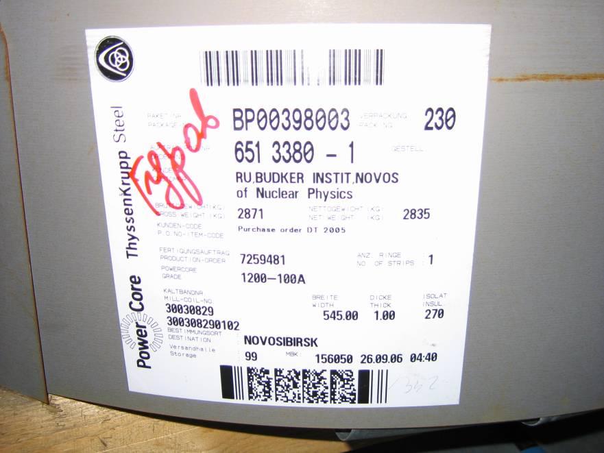
8 7.) Technical Specifications: Magnetic Steel 7.3) Testing of Steel 7.3.4)The thickness of the steel shall be checked on samples, taken at locations indicated above )The tenderers shall provide information at tender on the proposed methods for magnetic, electrical and physical measurements of the magnet steel. 7.4)Steel supplier 7.4.1)Steel of the described quality is available from a number of suppliers and the manufacturer has full liberty to choose any source of suitable material. CELLS believes that e.g. steel type A coated on both sides with Stabolit 70 will comply with this specification. CELLS has identified the supplier for this steel: ThyssenKrupp Electrical Steel GmbH (EBG) Altendorfer Str. 120 D Essen Germany 8
9 8.) Techn. Specs.: Laminations and Yokes 8.1)Laminations stamping 8.1.1)The manufacturer is responsible for achieving the required dimensional tolerances for all laminations to meet the mechanical specifications. 8.2)Lamination stamping tests 8.2.1)Prior to start production stamping and after each re-grinding of the stamping tools, a certain number of lamination will be punched and three of them shall be measured. In addition, after every 5000 laminations during the stamping operation, a lamination will be taken at random from the production line, and measured. The suitability of the lamination will be judged with respect to the lamination drawing that will have been approved by CELLS. The measurements shall be submitted to CELLS for approval )CELLS reserves the right to be present during all such measurements. 9
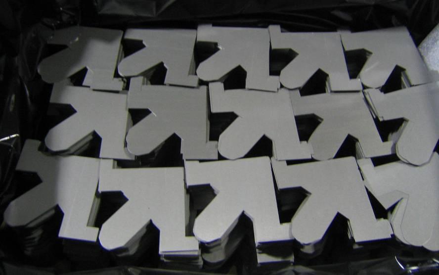
10 8.) Techn. Specs.: Laminations and Yokes 8.2)Lamination stamping tests 8.2.3)The tested laminations, duly marked with an identifying label, shall then be made available to CELLS for independent verification of dimensional tolerances )CELLS is entitled to reject any lamination which is not within tolerances, as specified in the appropriate drawing )The maximum burr at any location on the lamination must not exceed mm; no subsequent deburring operation will be permitted )Re-grinding of the tooling must be carried out at such intervals as are necessary to maintain the required dimensional tolerances of all laminations )After stamping, the laminations produced from each batch of steel shall be stored separately to allow the shuffling operation as described below to be undertaken. The batch of origin of all laminations shall continue to be identifiable. 10
11 8.) Techn. Specs.: Laminations and Yokes 8.2)Lamination stamping tests 8.2.8)In order to successfully carry out the shuffling operation, all steel delivered for use in Phase 2 of the contracts must be stamped and stored before commencing any further handling and processing operations on the laminations. The steel shall be protected against corrosion. 8.3)Laminations shuffling 8.3.1)This section applies only to laminations produced for use in the second phase )The required magnetic identity between the magnets requires appropriate shuffling of the laminations in such a way that each magnet contains steel representative of each steel production batch, in roughly equal proportions. Manufacturers shall therefore plan a strategy to achieve this, taking into account the number of steel batches required for the magnet production, and the expected variation of magnetic properties within each batch. 11

12 8.) Techn. Specs.: Laminations and Yokes 12
13 8.) Techn. Specs.: Laminations and Yokes 8.3) Laminations shuffling 8.3.3)Final details of the shuffling process shall be agreed with CELLS; these will depend on the results obtained during the magnetic testing of the steel and the periodic measurement of the laminations defined in section ) Yoke 8.4.1)Tenderers shall indicate whether it is their intention to stack and glue laminations to produce yokes in a final state or whether it is their intention to stack and weld the laminations to produce a yoke 13
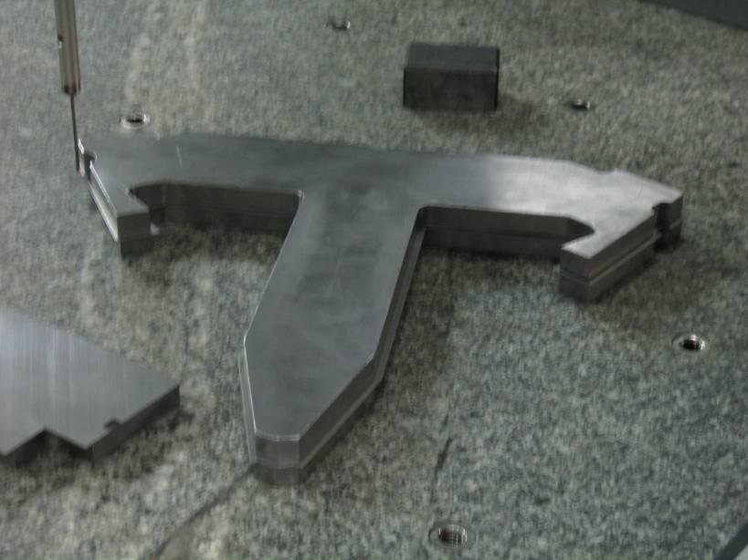
14 8.) Techn. Specs.: Laminations and Yokes 8.4) Yoke 8.4.2)Tenderers shall indicate whether it is their intention to perform further machining on one or more faces of the block after yoke assembly. Where such machining is proposed, tenderers shall give a clear explanation of how they intend to ensure that the specified dimensions required on the yoke will be achieved. In any case machining of the any part of the yoke is restricted to: a.) Machining of the pole profile b.) Machining of the reference planes for the alignment features, as set in section 3.5. c.) Machining of the reference for the support feet The pole has one machined end chamfer to correct the end field in order to provide the correct harmonic analysis. After magnetic measurements of the pre-series magnet the final shape of the end chamfer will be confirmed. 14
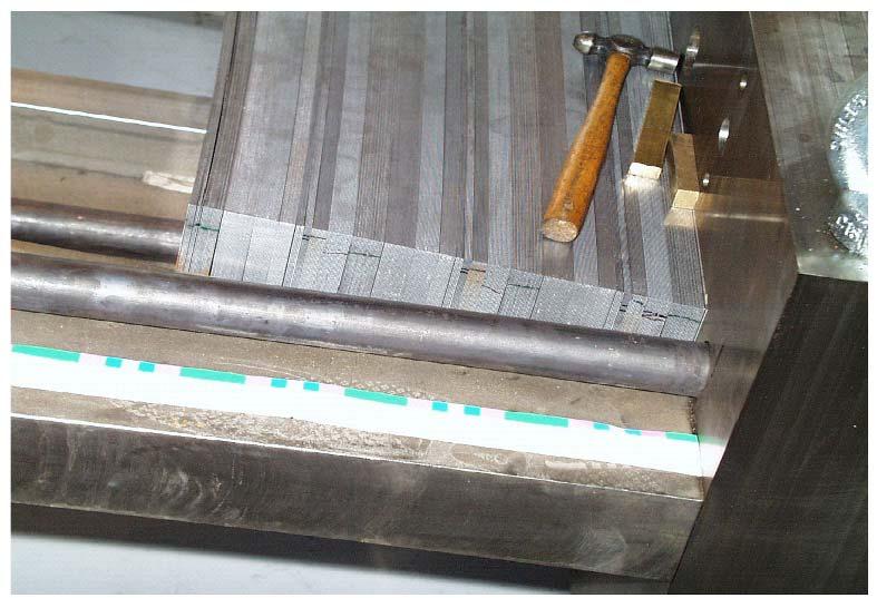
15 8.) Techn. Specs.: Laminations and Yokes 8.4) Yoke 8.4.3)During the stacking of the initial pre-series, a record shall be kept of the weight of laminations used for the yoke. After acceptance of the preseries, these weight will be defined as the standard weight of laminations in a given yoke )During stacking of the production magnet yokes, the number of laminations to be included in the yoke will be determined by weight, and shall be within plus or minus half the weight of a single lamination of the standard weight of laminations in a yoke block )The packing factor has to be at least 98 % and has to be within ±0.5 % for all of them. 15

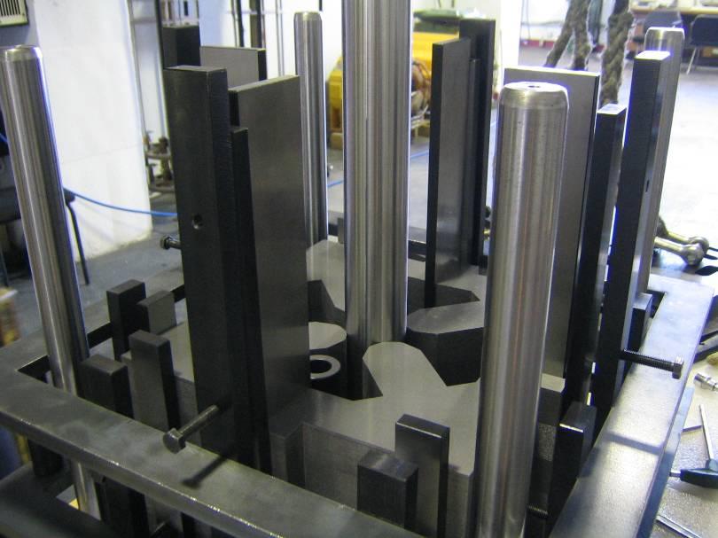

16 Stacking fixture 16


17 Fixture for the gluing Process 17
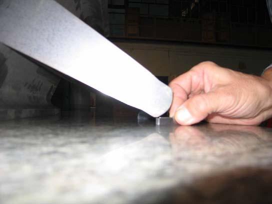
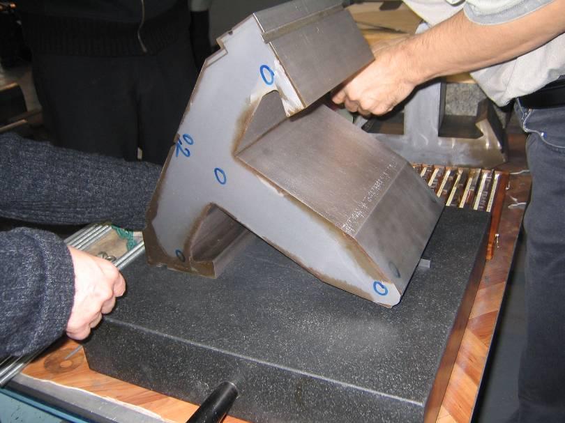
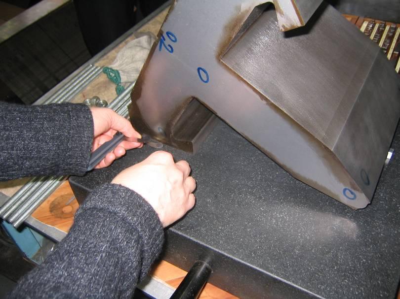

18 Mechanical Test of Yoke 18
19 8.) Techn. Specs.: Laminations and Yokes 8.5)Bending magnet ends 8.5.1)To control both the effective length and the integrated field quality of the bending magnet, the ends of the poles of each magnet will be chamfered, as specified on the appropriate drawing )To decide the length and the angle of the end chamfer a set of different chamfers, as specified on the appropriate drawing, will be produced during the first phase and a set of magnetic measurements will be taken for the pre-series magnet equipped with all different chamfers. After evaluation of the magnetic measurements done by CELLS the length and angle of the end chamfer to be machined on the production magnets will be communicated to the manufacturer before the second phase starts )Irrespective of the technique used for producing the end modification, the laminations that are to be included in the end region of the poles will be taken from the same stock of shuffled laminations as the unmodified pole region. 19

20 8.) Techn. Specs.: Laminations and Yokes chamfer OPERA-3D Measured 10.0º º º/15º ΔQx, ΔQy Qx, sim. Qy, sim. Qx, meas. Qy, meas End chamfer [degrees] 20
21 8.) Techn. Specs.: Laminations and Yokes 8.6)Mechanical yoke testing 8.6.1) After the laminations have been assembled and machined into a yoke the main geometrical dimensions will be carefully checked according to the tolerances of the relevant drawings. Features that shall be controlled are: a.) Length measured at three different locations along the yoke. b.) Flatness of the whole assembly c.) Squareness of the sides and of the end faces d.) Longitudinal shape of the yoke will be checked with a jig, the construction of which is part of this contract )After assembling of the complete yoke the functional tolerances among which the distance between the reference surfaces on the top and bottom of the bending magnets and the median plane will be checked with the magnet both powered and unpowered. The dimensional controls are specified on the appropriate drawings. 21
22 8.) Techn. Specs.: Laminations and Yokes 8.7)Protection and painting 8.7.1)After assembly and control, the yokes will be protected against rust by painting. Two-component epoxy paint shall be used, which the manufacturer shall ensure is hard and mechanically resistant. The unpainted areas, as indicated in the appropriate drawings shall be protected by a light oil or other rust preventative measures. The colour will be RAL

/μ 0 N*I B 0")


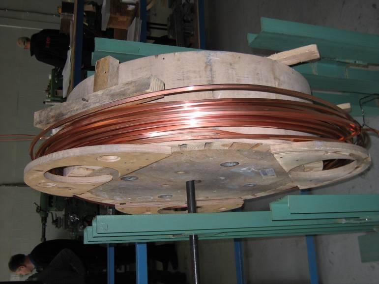
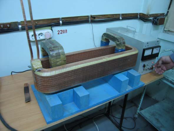
23 Size of Coils. Coils The currents and the windings of the coil have to make the excitation N*I = B 0 (g+l Fe /μ r )/μ 0 N*I B 0 g/μ 0 For the ALBA bending with a gap of 36 mm and a flux density of 1.42 T the excitation is: N*I = A*Wdgs This can be done by a larger number of windings or a high current. Coils 23
24 Coil Geometry Standard design is rectangular copper (or aluminium) conductor, with cooling water tube. Insulation is glass cloth and epoxy resin. Amp-turns (NI) are determined, but total copper area (A copper ) and number of turns (N) are two degrees of freedom and need to be decided. Current density: j = NI/A copper Optimum j determined from economic criteria. 24


25 Size of the Coil 2 layers A small number of layers needs more space in the longitudinal directions. A high number of layers needs more space for the magnets in the vertical direction. For the number of layers one has to make a compromise and it depend upon the machine 8 layers / 4 pancakes Space within the machine for the components should be as small as possible. 25
26 9.) Technical Specifications: Coils 9.1)Coils manufacturing 9.1.1) Bending magnets have two (2) coils. Each coil is made of four (4) individual pancakes. Each pancake is composed of 10 turns; therefore, each coil has 40 turns. The coils shall be manufactured using a solid copper conductor with a central hole for the passage of cooling water, according to the CELLS design )The coil is designed to have a maximum temperature rise in the cooling water of 10 C with a differential pressure of 7 bar. Under these conditions the maximum coil temperature will be 35 C. It is essential that the insulation system withstands repeated thermal cycling without mechanical or electrical failure )The coils will operate in a radiation environment, and must therefore be built using glass and epoxy resin insulation system. No materials other than those specified in this section of the specification will be permitted. The materials that will be used for insulation will be subject to written authorization from CELLS. 26


27 27


28 28
29 9.) Technical Specifications: Coils 9.1.4) Inter-turn resistance shall be provided by wrapping the copper conductor with a borosilicate glass cloth, half-lapped to produce a minimum insulation thickness of 0.5 mm turn-to-turn. After completion of winding, an outer ground insulation shall be provided by further layers of half-lapped glass cloth of minimum thickness 1.0 mm ) On completion of the coil winding, electrical and water terminations shall be attached to the leads ) Each pancake shall have one (normally closed) over-temperature switch, set to open an electrical circuit at 60 ±5 C. These switches shall be fitted each with two external leads or connections, and shall either be fitted before the impregnation process, or glued to the surface of the coil after impregnation. Whichever technique is used, the manufacturer will ensure that good thermal and mechanical contact is obtained using materials that meet the requirements of this specification ) All voids arising within the pancakes shall be packed with glass roving in order to avoid the occurrence of resin-rich areas and delamination. The material used shall conform to the glass requirements described below. 29
30 9.) Technical Specifications: Coils 9.1)Coils manufacturing 9.1.8)The insulation in the vicinity of the pancakes leads and terminations will require special attention, in order to provide adequate strength and to avoid the presence of excessive resin in that area. Glass roving or preformed glass epoxy inserts must be utilised in these areas, and all materials used must conform to the requirements described below ) The manufacturer shall estimate the degree of conductor keystoning that will occur in certain areas of the coil. Resulting voids consequently introduced into the coil must therefore be filled, using the methods indicated above in ) No joints within the pancakes will be permitted. 30
31 9.) Technical Specifications: Coils 9.2)Conductor 9.2.1)The copper shall be Cu-OF Oxygen free (ISO designation) annealed after cold work (dead soft fully annealed temper) )The copper shall be free of cracks, porosity and voids. It shall not have any tendency for hydrogen embrittlement. Very good characteristics for brazing are required as well as a ductibility which permits the winding of the conductor into magnet coils with tight bends )The composition shall be at minimum % Cu (+Ag).The oxygen content shall be kept below 10 ppm )The electrical resistivity shall be less than Ωm at 20 C )The uniformity of the conductor shall be such that the resistance of all coils constructed from it shall be equal to within +/-1%. 31
32 9.) Technical Specifications: Coils 9.3)Conductor supplier 9.3.1)Copper conductor of the described quality is available from a number of suppliers and the manufacturer has full liberty to choose any source of suitable material. CELLS has identified a supplier for a conductor that will comply with this specification: Luvata Kuparitie, P.O.Box 60 FIN Pori, Finland 32
33 9.) Technical Specifications: Coils 9.4)Conductor tests before winding 9.4.1)Test certificates shall be available relating to tests undertaken by the copper manufacturer, to include dimensions, resistivity and Brinell hardness )The cooling channel must permit the free passage of a 5.3 mm diameter ball )Before construction commences, the conductor shall be hydraulically tested at a pressure of 100 bar for five minutes. Conductors revealing any evidence of leakage shall be rejected )Before the winding of the coil, the conductor shall be cleaned and sandblasted. 33
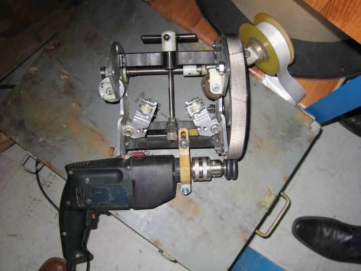
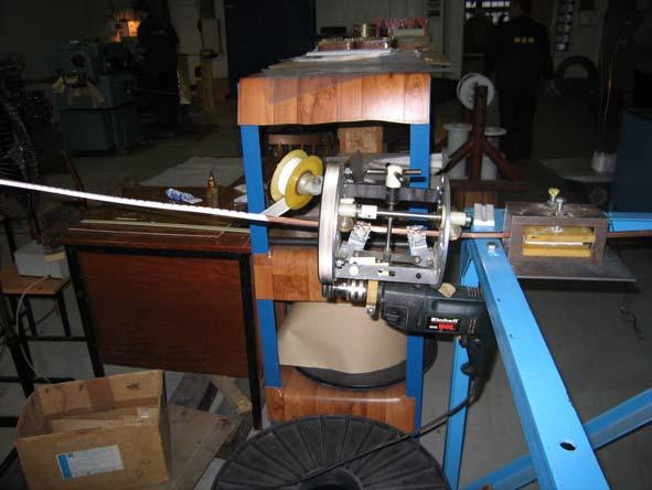
34 9.5)Pancake winding 9.) Technical Specifications: Coils 9.5.1) Scrupulous care shall be exercised at all stages of the coil construction in the handling of all the components, which shall be undertaken in a clean environment. All working surfaces shall be cleaned immediately prior to be used, and protective gloves shall be worn by all the staff involved. Quality control of this design will have to guarantee the lack of any conductive occlusion between wires (cutting, dust, ). Moreover, excessive hammering (hardening) of the conductor which could destroy the fibreglass tape, shall be avoided ) After completion of pancake winding, the pancakes shall be tested with a gas (helium or halogen) at a pressure of 15 bar for thirty minutes. The soundness of the pancake shall be checked at the end of the thirty minutes by passing the probe of a leak detector over the full outer surface of the pancake. This detector will be a mass spectrographic device tuned to the test gas, or similar system. Impregnation shall not be undertaken on any pancake exhibiting evidence of leakage. 34
35 9.) Technical Specifications: Coils 9.6)Pancake insulation and impregnation 9.6.1)The pancakes shall be vacuum impregnated. The use of a mould is considered to be essential, and such a mould must apply direct contact pressure to as great a surface area of the pancake as can be achieved ) Impregnation and curing shall be preceded by oven drying of a pancake and degassing of the resin, pancake and mould. Use of an open mould for the impregnation operation is preferred )The thickness of unreinforced resin on the surface of a finished pancake must not exceed 0.5 mm ) After completion, the resin on the pancakes must be fully transparent, with no colouriser or additive that would limit observation of the copper turns used within the resin system. No paint or other external coating will be allowed ) No pancake shall be repaired after its initial impregnation without the written approval of CELLS. 35
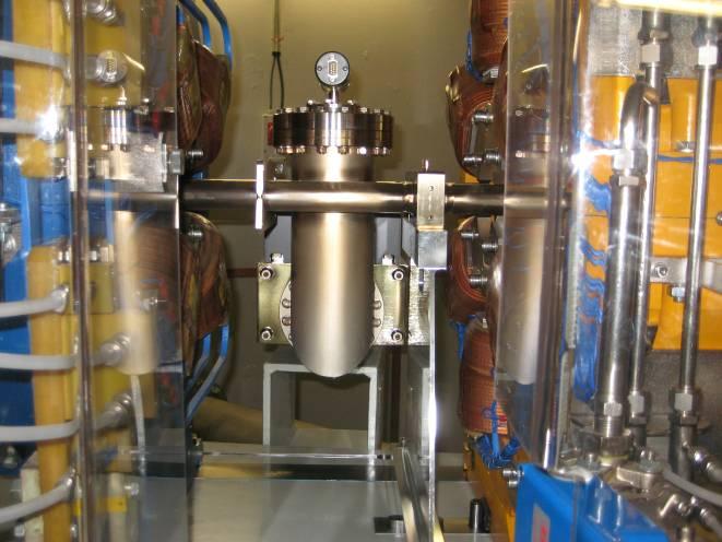
36 9.) Technical Specifications: Coils 9.7)Terminations of the coil 9.7.1)The magnets shall be designed with all mechanical services (i.e. cooling water manifolds) and all electrical connections (including power terminals) on the inside of the ring at the downstream end of the bending magnet ) Magnets shall be supplied with an inlet manifold and outlet manifold mounted on the mechanical services panel. The manifold shall be manufactured from metric stainless steel tube, grade 316, suitable for connection to the supply and return water system via a single Swagelok compression fitting onto each manifold. The manifold pipe will be mounted vertically on the mechanical services panel and the connection point will be at the bottom end of the tube ) Magnets shall be equipped with a water flow controller Eletta type at the outlet manifold. All part of this controller in contact with water will be in brass with Canigen coating. The Eletta switch will include a witness window for visual flow indication. 36
37 9.7)Terminations of the coil 9.7.4)The water connections on the coils shall be manufactured from phosphor bronze, and shall be attached to the coil by a silver brazing technique to give a system which is unaffected by demineralised water )The electrical connections for power terminals shall be mounted on the electrical and mechanical services panel which shall be rigidly supported on the magnet. These terminals shall be suitable to receive the incoming supply cable connectors, and will be designed to withstand a maximum force of 50 kg exerted by the incoming cables on the terminals. The connection between the coil terminals and the services panel shall be the responsibility of the manufacturer )The manufacturer shall, during initial design, avoid locating any organic based material in the median plane of the magnet centre where it would be subject to long-term radiation damage from the beam. Coil water connections to the manifolds shall be well above and below the beamline. Where water conduits cross the beam-line horizontal plane, pipe work shall be metallic. 37
38 9.7)Terminations of the coil 9.) Technical Specifications: Coils 9.7.7)The coil terminals, the connection posts and all metallic parts connected to them will be protected against accidental contact by an insulating, transparent cover, which can only be removed by the use of tools; tenderers' proposals for this cover shall be described in the offer )The water connection between the coil terminals and the manifold shall be of non-conducting tube, having suitable mechanical properties, and suitable for use in a high radiation environment. Tenderers shall indicate in their quotation, the type of material that they propose for these tubes )The cabling of the over-temperature interlock switches shall be part of the contract. The two terminals of each switch shall be mounted on the electrical services board as specified ) A single terminal connection post able to receive a 10 mm 2 cable shall be provided for earthing the yoke. The manufacturer shall ensure that there is adequate electrical connection between the yoke, manifolds and other components so that all the exposed metallic parts of the magnet are safely earthed by this terminal post. 38
39 9.) Technical Specifications: Coils 9.8) Coils testing 9.8.1)The brazed termination shall be tested at a pressure of 60 bars for 10 minutes ) During the total immersion of each coil in water the conductor shall be pressurised at 30 bar with water and sealed. The pressure shall be recorded, and any drop of pressure larger than 2 % during the 24 hours period shall result in rejection of the coil ) The water flow for each of the water channels in a coil shall be separately measured with a pressure differential across the channel of 7 bar. The flow rate shall not be less than the flow rate, as calculated by the manufacturer and communicated to CELLS during the design phase, on which the coil thermal calculations are based. The flow in any coil shall also be in the range of ±10% of the mean for all coil flow measurements )The electrical resistance of all coils shall be measured with a DC bridge. The values shall be corrected to 23 C, and must be within ±1% of the mean value for all coils. 39
40 9.) Technical Specifications: Coils 9.8)Coils testing 9.8.5) Each coil shall be immersed in tap water at ambient temperature, but with the terminals exposed above the water level. Any other part of the coil body not then completely immersed shall be covered with wet cloths the ends of which are in contact with the water. The following test sequence shall then be carried out: (a) Record insulation resistance between coil terminals and water bath, using minimum voltage of kv. Insulation resistance shall above 50 MOhm. (b) Apply direct voltage of 5 kv between coil terminals and water bath for one minute, and record the leakage current; (c) Repeat measurement as in (a). Any coil exhibiting evidence of breakdown or significant changes of insulation resistance during these tests shall be rejected. 40
41 9.8)Coils testing 9.) Technical Specifications: Coils 9.8.6) After completion of the tests in each coil shall be energised until the coil temperature increases to 60 C, as measured by the change in electrical resistance. During this period water shall be sealed within the conductor by means of a valve. On attaining the required temperature the current shall be interrupted and water at room temperature allowed to flow through the coil until the conductor again assumes the ambient temperature, as measured by the conductor resistance. The valve shall then again be closed and the foregoing cycle repeated fifty (50) times. The manufacturer may wish to undertake this procedure on a number of coils simultaneously. This test shall be performed in each one of the coils for the pre-series bending magnet and for one in each 5 coils for the series production ) On completion of the thermal cycling the insulation tests described in shall be repeated, and significant changes of insulation resistance or breakdown characteristics shall again be sufficient reason for rejection of a coil. Any coil exhibiting evidence of cracking or delamination shall also be rejected. 41
42 9.) Technical Specifications: Coils 9.8)Coils testing 9.8.8) Immediately after the test described in the coil shall be tested by using it as the secondary winding of a transformer. A maximum voltage of 2 kv RMS shall be induced across the coil terminations for a period of one minute, and the corresponding primary current recorded. Any indication of short-circuiting between turns shall result in rejection of the coil. 42
43 10.) MECHANICAL AND ELECTRICAL TESTS ON COMPLETE MAGNETS 10.1)Mechanical and electrical tests on complete pre-series magnet ) After the magnets have been assembled with coils and cooling hoses, the complete assembly will be measured to ensure that it complies with the dimensional tolerances as specified ) All the dimensions will be checked according to the appropriate magnet assembly drawing )The measuring techniques will be specifically designed to check each and all of the dimensions and dimensional tolerances defined in the appropriate assembly drawing and in this specification. These will be subject to CELLS approval. Manufacturers are requested to give details of their proposed assembly measurement techniques in their tenders. 43
44 10.) MECHANICAL AND ELECTRICAL TESTS ON COMPLETE MAGNETS 10.1)Mechanical and electrical tests on complete pre-series magnet ) As an essential part of these tests and the subsequent production checks, the manufacturer shall develop and manufacture an instrument that is capable of making precision measurements of the gap region. This instrumentation is required to have the following features: a.) a measurement sensitivity and reproducibility equal to or better than ±10 µm; b.) a monitorable electrical output, allowing gap dimensions to be continuously measured as the gauge traverses through the magnet; c.) accuracy and sensitivity unaffected by magnetic fields, i.e. to be capable of performing the required measurements with the bending magnet powered. 44
45 10.) MECHANICAL AND ELECTRICAL TESTS ON COMPLETE MAGNETS 10.1)Mechanical and electrical tests on complete pre-series magnet ) A direct voltage of 5 kv shall be applied between the terminals of each coil and its magnet yoke for one minute. Any coil showing evidence of breakdown, indicated by a leakage resistance of less than 50 MΩ, shall be rejected ) A maximum d.c. operating current test with a coil excitation of 530 A shall be carried out for a period of at least two hours, with cooling water circuits set to provide a differential pressure not greater than 7 bar. During this test, the water inlet and outlet temperature shall be monitored, and the temperature of coil surfaces and all coil interconnections and terminals checked with contact thermometers. Results shall be judged with respect to the appropriate magnet thermal specifications. Any coil showing evidence of overheating, local hot spots or other faults during this period shall be rejected. This test can be performed at the commencement of the magnet measuring sequence, with the magnet connected to a power supply and cooling water. 45
46 10.) MECHANICAL AND ELECTRICAL TESTS ON COMPLETE MAGNETS 10.1)Mechanical and electrical tests on complete pre-series magnet )The manufacturer shall demonstrate the operating efficiency of the over-temperature switches by raising the temperature of each coil to the value (60 C) at which the switches are guaranteed to operate. The technique that is to be used for the necessary overheating shall be agreed with CELLS. Because of the danger of damage to the coil, CELLS strongly prefers a method involving the external heating of the circulating water. Details of the proposed method shall be included in the tender )The manufacturer shall demonstrate the operating efficiency of the water flow switch by restricting slowly the supply of water with the magnet unpowered. 46
47 10.) MECHANICAL AND ELECTRICAL TESTS ON COMPLETE MAGNETS 10.2) Mechanical and electrical tests on complete production magnets ) After the magnets have been assembled with coils, cooling hoses and mounting brackets fitted, the complete assembly will be measured to ensure that it complies with the dimensional tolerances as specified ) All the dimensions will be checked according to the appropriate magnet assembly drawing ) A direct voltage of 5 kv shall be applied between the terminals of each coil and its magnet yoke for one minute. Any coil showing evidence of breakdown, indicated by a leakage resistance of less than 50 MΩ, shall be rejected. 47
48 10.) MECHANICAL AND ELECTRICAL TESTS ON COMPLETE MAGNETS 10.2) Mechanical and electrical tests on complete production magnets ) A maximum d.c. operating current test with a coil excitation of 530 A shall be carried out for a period of at least two hours, with cooling water circuits set to provide a differential pressure not greater than 7 bar. During this test, the water inlet and outlet temperature shall be monitored, and the temperature of coil surfaces and all coil interconnections and terminals checked with contact thermometers. Results shall be judged with respect to the appropriate magnet thermal specifications. Any coil showing evidence of overheating, local hot spots or other faults during this period shall be rejected. This test can be performed at the commencement of the magnet measuring sequence, with the magnet connected to a power supply and cooling water. 48
49 10.) MECHANICAL AND ELECTRICAL TESTS ON COMPLETE MAGNETS 10.3)Acceptance tests after delivery ) After delivery, the bending magnets shall be visually inspected for mechanical damage suffered in transit. Any such damage shall be reported to the manufacturer. Possible repair shall be subject to agreement with CELLS. Where the damage has resulted in alteration to the magnet iron geometry or to the soundness or shape of coil conductor, insulation or terminals, the magnet shall be rejected ) Electrical tests shall be carried out by staff of CELLS after delivery. The manufacturer has the right to be represented during these tests but shall notify CELLS in writing if this right is to be exercised ) A direct voltage of 5 kv will be applied between the terminals of each coil and its magnet yoke for one minute. Any coil showing evidence of breakdown, indicated by a leakage resistance of less than 50 MΩ, shall be rejected )The magnet will be energised at the maximum current of 530 A for a period of at least two hours. Any coil showing evidence of breakdown, local hot spots or other faults during this period shall be rejected. 49
50 Travellers 50
51 Travellers 51
52 Travellers 52
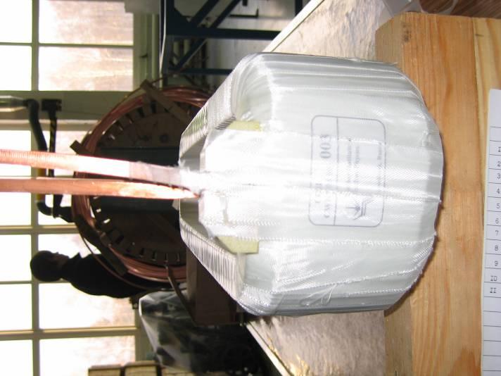
53 Travellers 53
54 Travellers 54
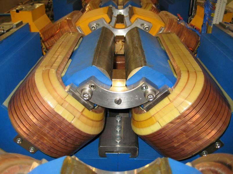
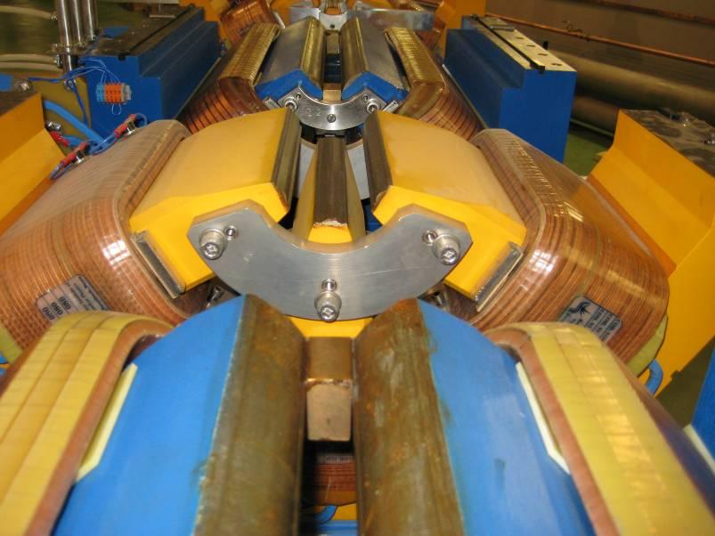
55 1.1. PARAMETERS of THE SEGMENT No. 012 PARAMETERS MEASURED 1 Drawing of the segment CWLF 2 Temperature conditions in the oven Normal 3 Visual checking for quality of segment (cracks, glue, color and etc) Length of segment in 3 checkpoints. Nominal value is 150± 0.1mm OK mm mm mm The gap between surfaces of segment and base plate (2 measures). Nominal : 0.02 mm mm mm 55
56 The gap between shims and base plate (4 measures). Nominal : 10 ± mm mm mm mm mm Non-perpendicularity of surfaces of the segment (3 measures). Nominal: 0.1 mm mm mm mm 56
57 Travellers 57
58 Travellers This has to be done for all 4 coils 58
59 Travellers 59
60 Travellers 60
61 Travellers 61
62 11.) PACKING AND TRANSPORTATION 11.1) Packing )The contractor will submit to CELLS a solution for the packing. This packing will have to use the classical handling tools. The magnet packed shall be protected against the elements, the projections and the breaks during transportation and storage )The packing of each magnet shall be dust proof, water proof and will have to protect the steel parts against the oxidation. Moreover, the pieces shall be protected against the strain, impacts and rubbing which can damage their surfaces ) A particular protection shall be required for brittle parts (reference surfaces, electrical connections and coils) )The coils shall be rinsed, dried and sealed before expedition in order to avoid any frost. 62
63 11.) PACKING AND TRANSPORTATION 11.2) Transportation ) The contractor will include in his tender the transport from the factory : a.) to the site where CELLS will control and measure the magnets. This place will not be necessarily in the CELLS site. b.) or to the storage area that CELLS will indicate. This storage area will be at CELLS site or nearby )The contractor keeps the responsibility of the bending magnets until the delivery to one of the sites listed above. CELLS will supply the local handling tools )The transfer of risks shall take place when the load is laid down on the ground. 63


64 Assembling of Yokes 64


65 Space between Magnets 65
66 Results of magnetic Measurements Normalized Field Normalized Excitation Curve Up Down Theory Field (T) Magnetic Field in the Centre Dipole Quadrupole Current (A) Transverse (mm) Field (T) Magnetic Field (Centre) Dipole Quadrupole Transverse (mm) Field [Tesla] Vertical field along trajectory Positive Negative s [m] 66
67 Results of magnetic Measurements Normal Quadrupole along trajectory Normal Quadrupole along trajectory Quadrupole [Tesla/m] positive negative s [m] Quadrupole [Tesla/m] positive negative s [m] 67
68 Results of magnetic Measurements Magnetic Field Flux Density / % Number of Magnets Integrated Gradient Tot-Gradient Integr_Gradient Number of Magnets 68
69 Results of magnetic Measurements Radius... Radius [Hard edge] /- 0.04% Number of Magnets Length [Hard edge] Length / % Number of Magnets 69
70 Results of magnetic Measurements Scaling factor Scaling Factor Number of Magnets +/-0.2% 6.4 Edge Angle [Hard edge] Edge Angle Number of Magnets +/- 3% 70

71 Higher Multipoles in a Quadrupole Typical results from a quadrupole ΔB/B, for n> x10-5 1x10⁻⁴ 2x10⁻⁴ 5x10⁻⁴ 1x10⁻³ 2x10⁻³ 3x10⁻³ MORE Q500CX-021-NORMALCOMPONENTS Q500CX-021-SKEW COMPONENTS Normal Harm. Bn*10-4 /B A 10 0 A 150 A 180A 220A 225A Skew Harm. An*10-4 /B A 100A 150 A 18 0 A 220A 225A Harmonic number Harmonic number 71

72 B3/B2 at 100 A, r=15 mm BO-Q340C-002 BO-Q340C-003 BO-Q340C-004 BO-Q340C-007 BO-Q340C-008 BO-Q340C-009 BO-Q340C-010 BO-Q340C-012 BO-Q340C-013 BO-Q340C-014 BO-Q340C-015 BO-Q340C-017 BO-Q340C-018 BO-Q340C-019 BO-Q340C-021 BO-Q340C-022 BO-Q340C-023 BO-Q340C-024 BO-Q340C-025 BO-Q340C-027(1st) BO-Q340C-027(2nd) BO-Q340C-027(4th) BO-Q340C-028 BO-Q340C-029 BO-Q340C-031(1st) BO-Q340C-031(2nd) BO-Q340C-032 BO-Q340C-033 BO-Q340C-034 BO-Q340C-035 BO-Q340C-037 NOMINAL Sextupole Component in a Quadrupole <B3/B2> = σ = 1 % B3/B2 Magnet B3/B2 at 100 A, r=15 mm <B3/B2> = σ = 1 % Ratio B3/B2 at 100 A and 15 mm Nominal should be Average is BO-Q340C-002 BO-Q340C-003 BO-Q340C-004 BO-Q340C-007 BO-Q340C-008 BO-Q340C-009 BO-Q340C-010 BO-Q340C-012 BO-Q340C-013 BO-Q340C-014 BO-Q340C-015 BO-Q340C-017 BO-Q340C-018 BO-Q340C-019 BO-Q340C-021 BO-Q340C-022 BO-Q340C-023 BO-Q340C-024 BO-Q340C-025 BO-Q340C-027(1st) BO-Q340C-027(2nd) BO-Q340C-027(4th) BO-Q340C-028 BO-Q340C-029 BO-Q340C-031(1st) BO-Q340C-031(2nd) BO-Q340C-032 BO-Q340C-033 BO-Q340C-034 BO-Q340C-035 BO-Q340C-037 Magnet Dispersion of the B3/B2 value with respect to the average.there are a couple of measurements (#13 and #31-2nd) that need to be re-evaluated 72 D. Einfeld, CELLS D. Einfeld, CELLS CAS, Bruges, 21 st Oct. 2008, June. NSRRC 2009 B3/B2

73 Higher Multipoles in a Sextupole Typical results from a sextupole The magnets are looking pretty good. All the higher harmonics from the quadrupole and sextupole don t have any influence upon the dynamic aperture S NORMAL COMPONENTS S SKEW COMPONENTS 8 8 Normal Harm. B n*10-4 /B A 100 A 150 A 175 A 200 A A 10 0 A 150 A 175 A 200 A Harmonic number Har monic number 73
74 Acknowledgment Many thanks to Niels Mark Jack Tanabe 74
75 Thank you very much And I wish you a lot of luck in your carrier (einfeld@cells.es) 75
This chapter gives details of the design, development, and characterization of the
 CHAPTER 5 Electromagnet and its Power Supply This chapter gives details of the design, development, and characterization of the electromagnets used to produce desired magnetic field to confine the plasma,
Status of the PLS-II Magnet Design and Fabrication
 Journal of the Korean Physical Society, Vol. 56, No. 6, June 2010, pp. 1964 1970 Status of the PLS-II Magnet Design and Fabrication D. E. Kim, K. H. Park, H. G. Lee, H. S. Han, Y. G. Jung, H. S. Suh, Y.
INFN LNF DAΦNE. DAΦNE Storage Ring. Laminated Yoke Quadrupole Low carbon steel Magnetil B-C
 and Storage Ring In 1993 the Company was awarded by INFN-LNF a contract for the turn-key construction of the Transfer Lines for the e+e-φ-factory DAΦNE in Frascati - Rome. The contract included resistive
Collaboration between CELLS in Barcelona and BINP in Novosibirsk in the construction of ALBA Synchrotron
 Collaboration between CELLS in Barcelona and BINP in Novosibirsk in the construction of ALBA Synchrotron Josep Campmany on behalf of CELLS Accelerators Division 10/11/2011 J. Campmany ALBA- CELLS (Barcelona)
Distribution transformers Efficiency over life-cycle
 Distribution transformers Efficiency over life-cycle ABB a global leader ABB is a global leader in Power and Automation technologies that enable utility and industry customers to improve performance while
Excitation system is of Static Silicon Excitation System, including excitation transformer, thyristors, and AVR.
 Turbo - Generator Type: QF Series 1. General The generator is a two pole, cylindrical rotor type synchronous machine, directly coupled with steam turbine. It has a closed-circuit cooling system to cool
Guideline No.: E-07(201610) E-07 TRANSFORMERS. Issued date: October 28,2016. China Classification Society
 E-07 TRANSFORMERS. Issued date: October 28,2016. China Classification Society") Guideline No.: E-07(201610) E-07 TRANSFORMERS Issued date: October 28,2016 China Classification Society Foreword: This Guide is a part of CCS Rules, which contains technical requirements, inspection and
Guideline No.: E-07(201610) E-07 TRANSFORMERS Issued date: October 28,2016 China Classification Society Foreword: This Guide is a part of CCS Rules, which contains technical requirements, inspection and
CHAPTER 3 DESIGN OF THE LIMITED ANGLE BRUSHLESS TORQUE MOTOR
 33 CHAPTER 3 DESIGN OF THE LIMITED ANGLE BRUSHLESS TORQUE MOTOR 3.1 INTRODUCTION This chapter presents the design of frameless Limited Angle Brushless Torque motor. The armature is wound with toroidal
M-11 MARINE DIESEL ENGINE FUEL INJECTOR
 Guideline No.M-11(201510) M-11 MARINE DIESEL ENGINE FUEL INJECTOR Issued date: 20 October 2015 China Classification Society Foreword This Guideline constitutes the CCS rules, and establishes the applicable
Guideline No.M-10(201510) M-10 Marine Diesel Engine Fuel Injection Pump
 M-10 Marine Diesel Engine Fuel Injection Pump") Guideline No.M-10(201510) M-10 Marine Diesel Engine Fuel Injection Pump Issued date: 20 th October, 2015 China Classification Society Foreword This Guideline is a part of CCS Rules, which contains technical
Guideline No.M-10(201510) M-10 Marine Diesel Engine Fuel Injection Pump Issued date: 20 th October, 2015 China Classification Society Foreword This Guideline is a part of CCS Rules, which contains technical
PF Coil Fabrication Overview
 PF Coil Fabrication Overview PF Coils Information Meeting Barcelona - 15 th October 2012 This presentation is intended for reference purposes only and is not a legally binding document PF Building Layout
Guideline No.: E-07(201501) E-07 TRANSFORMERS. Issued date: October 20,2015. China Classification Society
 E-07 TRANSFORMERS. Issued date: October 20,2015. China Classification Society") Guideline No.: E-07(201501) E-07 TRANSFORMERS Issued date: October 20,2015 China Classification Society Foreword: This Guide is a part of CCS Rules, which contains technical requirements, inspection and
Guideline No.: E-07(201501) E-07 TRANSFORMERS Issued date: October 20,2015 China Classification Society Foreword: This Guide is a part of CCS Rules, which contains technical requirements, inspection and
34-SDMS-01 SPECIFICATIONS FOR
 SPECIFICATIONS FOR M V DROPOUT FUSE CUT OUTS This specification is property of SEC and subject to change or modification without any notice CONTENTS C l a u s e s: Page No. 1- SCOPE 3 2- CROSS REFERENCES
Extended requirements on turbogenerators
 , Siemens AG, Mülheim/Ruhr, Germany Extended requirements on turbogenerators due to changed operational regimes siemens.com Table of Content Evaluation of current operation regimes Extended requirements
The g-2 Project at FNAL. Horst Friedsam John Kyle IWAA 2014 at Beijing October 2014
 Horst Friedsam John Kyle IWAA 2014 at Beijing 13-17 October 2014 Outline History and project purpose P5 and the Muon Campus development The meaning of the gyromagnetic ratio g Alignment requirements Status
Guideline No.: E-07(201712) E-07 TRANSFORMERS. Issued date: December 26, China Classification Society
 E-07 TRANSFORMERS. Issued date: December 26, China Classification Society") Guideline No.: E-07(201712) E-07 TRANSFORMERS Issued date: December 26, 2017 China Classification Society Foreword: This Guide is a part of CCS Rules, which contains technical requirements, inspection
Guideline No.: E-07(201712) E-07 TRANSFORMERS Issued date: December 26, 2017 China Classification Society Foreword: This Guide is a part of CCS Rules, which contains technical requirements, inspection
Resin Impregnated Paper Bushing, Oil to SF 6. , Type GSBK
 1ZSC563-AAA en, Rev. 2 Resin Impregnated Paper Bushing, Oil to SF 6, Type GSBK Technical guide This Technical Guide has been produced to allow transformer manufacturers, and their designers and engineers,
LINE CONDITIONERS USER'S GUIDE
 LINE CONDITIONERS USER'S GUIDE PE 1411/10 (9415 014 11 101) PE 1412/10 (9415 014 12 101) PE 1413/10 (9415 014 13 101) PE 1411/15 (9415 014 11 151) PE 1412/15 (9415 014 12 151) PE 1413/15 (9415 014 13 151)
1ZSC AAA EN, REV. 7. Transformer bushings type GSBK Technical guide
 1ZSC563-AAA EN, REV. 7 Transformer bushings type GSBK Technical guide Original instruction The information provided in this document is intended to be general and does not cover all possible applications.
AIR COOLED RECTIFIER SPECIFICATION S-50-A
 SPECIFICATIONS AIR COOLED RECTIFIER Spec50a1 5JAN1999 SPECIFICATION S-50-A HIGH VOLTAGE SINGLE TRANSFORMER AIR COOLED RECTIFIER Standard output power range: 250 to 600 volts at 100 to 1,200 amperes TECHNICAL
4.1. Manufacturing field F2 Preformed and field coil windings
 4.1 Manufacturing field F2 Preformed and field coil windings 4.1.2.2 Manufacturing field F2 - Preformed and field coil windings 4.1.2.2.1 Range of services preformed coils One of the most important areas
SEMITOP2,3,4 Press-Fit
 Mounting Instruction SEMITOP2,3,4 Press-Fit Revision: 03 Issue date: 2017-08-28 Prepared by: Roberto Agostini Approved by: Werner Obermaier Keyword: SEMITOP, mounting instructions, one screw mounting,
UPDATE ON THE LHC MAIN MAGNETS. Lucio Rossi CERN - LHC MAC 15
 UPDATE ON THE LHC MAIN MAGNETS Lucio Rossi CERN - LHC MAC 15 Content Cable Components Production of dipoles and learing curves Fiedl quality Collared cois CM production Results and Delivery Plan for dipoles
M. A. Green, and S. Yu Lawrence Berkeley National Laboratory, Berkeley CA 94720, USA
 LBNL-48445 SCMAG-749 SUPERCONDUCTING MAGNETS FOR INDUCTION LINAC PHASE-ROTATION IN A NEUTRINO FACTORY M. A. Green, and S. Yu Lawrence Berkeley National Laboratory, Berkeley CA 94720, USA ABSTRACT The neutrino
INDUCTION MOTOR. There is no physical electrical connection to the secondary winding, its current is induced
 INDUCTION MOTOR INTRODUCTION An induction motor is an alternating current motor in which the primary winding on one member (usually the stator) is connected to the power source and a secondary winding
1ZSC AAA en, Rev. 6. Resin impregnated paper bushing, oil to SF 6., type GSBK Technical guide
 1ZSC563-AAA en, Rev. 6 Resin impregnated paper bushing, oil to SF 6, type GSBK Technical guide Original instruction The information provided in this document is intended to be general and does not cover
31-SDMS-02 REV. 01 SPECIFICATIONS FOR
 31-SDMS-02 REV. 01 SPECIFICATIONS FOR LOW VOLTAGE DISTRIBUTION PILLAR This specification is property of SEC and subject to change or modification without any notice C O N T E N T S S. NO. D E S C R I P
To study the constructional features of ammeter, voltmeter, wattmeter and energymeter.
 Experiment o. 1 AME OF THE EXPERIMET To study the constructional features of ammeter, voltmeter, wattmeter and energymeter. OBJECTIVE 1. To be conversant with the constructional detail and working of common
Generators for the age of variable power generation
 6 ABB REVIEW SERVICE AND RELIABILITY SERVICE AND RELIABILITY Generators for the age of variable power generation Grid-support plants are subject to frequent starts and stops, and rapid load cycling. Improving
Maximum output power with circulator Wo 6 kw. Maximum output power without circulator Wo 5 kw
 Packaged, metal-ceramic, water cooled continuouswave magnetron with integral RF cathode filter intended for use in industrial microwave heating applications. The tube features a quick- heating cathode,
SFI SPECIFICATION 34.1 EFFECTIVE: January 13, 2017*
 SFI SPECIFICATION 34.1 EFFECTIVE: January 13, 2017* PRODUCT: Screw-Type Superchargers 1.0 GENERAL INFORMATION 1.1 This SFI Specification establishes uniform test procedures and minimum standards for evaluating
GENERAL ATOMICS ITER CENTRAL SOLENOID MODULE FABRICATION
 GENERAL ATOMICS ITER CENTRAL SOLENOID MODULE FABRICATION January 2018 ITER Central Solenoid The heart of the international fusion energy device The Central Solenoid (CS) is the heart of ITER. The 5-story,
Physics12 Unit 8/9 Electromagnetism
 Name: Physics12 Unit 8/9 Electromagnetism 1. An electron, travelling with a constant velocity, enters a region of uniform magnetic field. Which of the following is not a possible pathway? 2. A bar magnet
Fabrication of 12 GeV Prototype Quadrupoles 1. Introduction 2. Design 3. Fabrication
 Fabrication of 12 GeV Prototype Quadrupoles T. Hiatt, K. Baggett, M. Beck, L. Harwood, J. Meyers and M. Wiseman Thomas Jefferson National Accelerator Facility, Newport News, Virginia 23606 1. Introduction
Unified requirements for systems with voltages above 1 kv up to 15 kv
 (1991) (Rev.1 May 2001) (Rev.2 July 2003) (Rev.3 Feb 2015) (Corr.1 June 2018) Unified requirements for systems with voltages above 1 kv up to 15 kv 1. General 1.1 Field of application The following requirements
CLASSIFICATION NOTES. Type Testing Procedure for. Crankcase Explosion Relief Valves
 CLASSIFICATION NOTES Type Testing Procedure for Crankcase Explosion Relief Valves Contents 1. Scope, Application 2. Recognized Standards 3. Purpose 4. Test Facilities 5. Explosion Test Process 6. Testing
CAST RESIN DISTRIBUTION TRANSFORMERS 2016 EDITION
 CAST RESIN DISTRIBUTION TRANSFORMERS 2016 EDITION TMC TRANSFORMERS - GLOBAL NETWORK UK & IRELAND SPAIN NORTH AMERICA & CANADA GERMANY SWITZERLAND BENELUX & AUSTRIA ITALY POLAND INDIA CENTRAL & SOUTH AMERICA
B. Base occupied space sound level estimates on ARI 885. C. Terminal heating coils shall conform to ARI 410.
 PART 1 - GENERAL 1.01 Purpose: A. This standard is intended to provide useful information to the Professional Service Provider (PSP) to establish a basis of design. The responsibility of the engineer is
SERIES TAP-CHANGER
 SERIES 090 - TAP-CHANGER Main characteristics This is an off-circuit tap changer. It means DO NOT OPERATE WHILE THE TRANSFORMER IS ENERGISED. Main characteristics of this tap-changer series are: dimensional
Doc:TED 11(794)W 1 September 2012 Draft Standard Automotive Vehicles - Windscreen Wiping System for 3 Wheeler Vehicles - Specification
W 1 September 2012 Draft Standard Automotive Vehicles - Windscreen Wiping System for 3 Wheeler Vehicles - Specification") For Comments only Doc:TED 11(794)W 1 September 2012 Draft Standard Automotive Vehicles - Windscreen Wiping System for 3 Wheeler Vehicles - Specification Not to be reproduced without permission Last date
For Comments only Doc:TED 11(794)W 1 September 2012 Draft Standard Automotive Vehicles - Windscreen Wiping System for 3 Wheeler Vehicles - Specification Not to be reproduced without permission Last date
SSC-JE STAFF SELECTION COMMISSION ELECTRICAL ENGINEERING STUDY MATERIAL ELECTRICAL MACHINES
 1 SSC-JE STAFF SELECTION COMMISSION ELECTRICAL ENGINEERING STUDY MATERIAL 28-B/7, Jia Sarai, Near IIT, Hauz Khas, New Delhi-110016. Ph. 011-26514888. www.engineersinstitute.com 2 CONTENT 1. : DC MACHINE,
MICHIGAN DEPARTMENT OF TRANSPORTATION SPECIAL PROVISION FOR PAVEMENT RIDE QUALITY (MEAN ROUGHNESS INDEX ACCEPTANCE CRITERIA)
") MICHIGAN DEPARTMENT OF TRANSPORTATION SPECIAL PROVISION FOR PAVEMENT RIDE QUALITY (MEAN ROUGHNESS INDEX ACCEPTANCE CRITERIA) CFS:TEH 1 of 10 APPR:KPK:JFS:07-07-16 FHWA:APPR:07-15-16 a. Description. This
MICHIGAN DEPARTMENT OF TRANSPORTATION SPECIAL PROVISION FOR PAVEMENT RIDE QUALITY (MEAN ROUGHNESS INDEX ACCEPTANCE CRITERIA) CFS:TEH 1 of 10 APPR:KPK:JFS:07-07-16 FHWA:APPR:07-15-16 a. Description. This
Solenoid Magnets for the Front End of a Neutrino Factory
 Solenoid Magnets for the Front End of a Neutrino Factory M.A. Green and S.S. Yu Lawrence Berkeley National Laboratory, Berkeley CA 94720 J.R. Miller and S. Prestemon National High Magnetic Field Laboratory,
GENERAL ATOMICS ITER CEnTRal SolEnoId ModulE FabRICaTIon September 2018
 GENERAL ATOMICS ITER Central Solenoid Module Fabrication September 2018 ITER Central Solenoid The heart of the international fusion energy device The Central Solenoid (CS) is the heart of ITER. The 5-story,
The introduction of Lead Crystal Battery
 The introduction of Lead Crystal Battery (1). Brief Introduction of Lead Crystal Battery Lead crystal battery is based on an in-depth study of both lead acid batteries and gel batteries features and defects,
PNO Condenser Bushings from 52 kv to 420 kv Oil-to-air - Oil-Impregnated Paper
 GE Grid Solutions PNO Condenser Bushings from 52 kv to 420 kv Oil-to-air - Oil-Impregnated Paper PNO bushings are capacitance graded bushings with an oil impregnated paper core. PNO bushings are conform
Titre / Title HIGH RELIABILITY RF COAXIAL LOADS AND ATTENUATORS GENERIC SPECIFICATION
 Date: December 19 th, 16 ISSUE: 1/B PAGE: 1 / 21 Titre / Title HIGH RELIABILITY RF COAXIAL LOADS AND ATTENUATORS GENERIC SPECIFICATION Rédigé par / Written by Responsabilité / Responsibility Date Signature
CLP POWER HONG KONG LIMITED. SUPPLY RULES March 2001
 CLP POWER HONG KONG LIMITED SUPPLY March 2001 ADVISORY SERVICE Advice concerning matters relating to the supply of electricity may be obtained free of charge from the Company. OTHER COMPANY PUBLICATIONS
15 steel septum magnets MSD of three types MSDA, MSDB, and MSDC, located around IP6;
 Chapter 10 Beam dumping 10.1 System and main parameters The dedicated beam dumping system of the LHC is sited in Point 6. The system is able to fastextract the beam from each ring in a loss-free way, to
013 : 2009 CEB SPECIFICATION MOULDED CASE CIRCUIT BREAKERS
 013 : 2009 CEB SPECIFICATION MOULDED CASE CIRCUIT BREAKERS FOR OVERHEAD NETWOKS CEYLON ELECTRICITY BOARD SRI LANKA Specification for MOULDED CASE CIRCUIT BREAKERS FOR OVERHEAD NETWOKS CEB Specification
Below, you can see the warning symbols used throughout the manual and their meaning.
 FMI60201 Frameless motors INTRODUCTION FMI-series frameless motors by Rozum Robotics are designed to provide motion as part of a motion system. Available in a range of sizes (dia. 40, 50, 60, 75 mm), FMI
Practice Note on the Sourcing of Threaded Rod Used for Foundation Bolts
 MATERIALS Practice Note on the Sourcing of Threaded Rod Used for Foundation Bolts Authors: Kevin Cowie, Alistair Fussell Affiliation: Steel Construction New Zealand Inc. Date: 20 th February 2018 Ref.:
UBC Technical Guidelines Section Edition Commissioning of Electrical Systems Page 1 of 5
 Page 1 of 5 1.0 GENERAL 1.1 Coordination Requirements.1 UBC Building Operations Electrical Technical Support.2 UBC Energy & Water Services 2.0 REQUIREMENTS FOR COMMISSIONING AND TESTING 2.1 Testing.1 Unit
Reference Only. Inductance Frequency (μh) Tolerance Typ Max (MHz min.) 85 *
 Tolerance Typ Max (MHz min.) 85 *") P.1/10 CHIP COIL (CHIP INDUCTORS) LQM2HPN G0L REFERENCE SPECIFICATION 1. Scope This reference specification applies to LQM2HPN_G0 series, Chip Coil (Chip Inductors). 2. Part Numbering (ex) LQ M 2H P N
P.1/10 CHIP COIL (CHIP INDUCTORS) LQM2HPN G0L REFERENCE SPECIFICATION 1. Scope This reference specification applies to LQM2HPN_G0 series, Chip Coil (Chip Inductors). 2. Part Numbering (ex) LQ M 2H P N
www. ElectricalPartManuals. com WeSTinghouse Secondary Unit Substation Transformers (Power Centers) Descriptive Bulletin Page 1
 Descriptive Bulletin Page 1") WeSTinghouse Descriptive Bulletin 47-156 Page 1 liquid Filled, Self-Contained 112% 2500 Kva June, 1974 Supersedes DB 47-350, dated August 1972 E, D, C/2082/DB Descriptive Bulletin 47-156 Page 2 Westinghouse
WeSTinghouse Descriptive Bulletin 47-156 Page 1 liquid Filled, Self-Contained 112% 2500 Kva June, 1974 Supersedes DB 47-350, dated August 1972 E, D, C/2082/DB Descriptive Bulletin 47-156 Page 2 Westinghouse
1ZSE en, Rev. 3. Wall bushings, type GSA-AA Technical guide
 1ZSE 2750-112 en, Rev. 3 Wall bushings, type GSA-AA Technical guide Original instruction The information provided in this document is intended to be general and does not cover all possible applications.
Pre-lab Questions: Please review chapters 19 and 20 of your textbook
 Introduction Magnetism and electricity are closely related. Moving charges make magnetic fields. Wires carrying electrical current in a part of space where there is a magnetic field experience a force.
1 Product Description Check of the supplied Parts Notes Intended Use Current Collector... 3
 Order number 0813xx-... Contents 1 Product Description... 2 2 Check of the supplied Parts... 2 3 Notes... 2 4 Intended Use... 2 5 Current Collector... 3 6 Installation Sequence... 3 7 Pickup Guide... 7
Electronic Circuit Breaker ESS20-0..
 Electronic Circuit Breaker ES-0.. Description Electronic circuit breaker type ES-0.. is designed to ensure selective disconnection of individual loads in systems which are powered by a DC 4 V switch-mode
023 : 2006 CEB STANDARD. 12kV & 36kV LOAD BREAK SWITCHES CEYLON ELECTRICITY BOARD SRI LANKA
 023 : 2006 CEB STANDARD 12kV & 36kV LOAD BREAK SWITCHES CEYLON ELECTRICITY BOARD SRI LANKA Specification for 12kV & 36kV LOAD BREAK SWITCHES CEB Standard 023 : 2006 CEYLON ELECTRICITY BOARD No. 50, Sir
1ZSE EN, REV. 4. Wall bushings type GSA-AA Technical guide
 1ZSE 2750-112 EN, REV. 4 Wall bushings type GSA-AA Technical guide Original instruction The information provided in this document is intended to be general and does not cover all possible applications.
INTRODUCTION WARNING SIGNS AND THEIR MEANINGS
 INTRODUCTION FMI-series frameless motors by Rozum Robotics are designed to provide motion as part of a motion system. Available in a range of sizes (stator dia. 41, 51, 75 mm), FMI motors are suitable
Cable thermocouple Model TC40
 Electrical temperature measurement Cable thermocouple Model TC40 WIKA data sheet TE 65.40 Applications For direct installation into the process Machine building Motors Bearings Pipelines and vessels Special
Tension and Compression Load Cell Model 8435
 Technical Product Information w Tension and Compression Load Cell 1. Introduction... 2 2. Preparing for use... 2 2.1 Unpacking... 2 2.2 Using the instrument for the first time... 2 2.3 Grounding and potential
Thermal Analysis of Electric Machines Motor-CAD
 Thermal Analysis of Electric Machines Motor-CAD Create, Design, Engineer! Brief Look at MotorCAD geometry input using dedicated editors select materials, cooling options All difficult heat transfer data
PRODUCT SPECIFICATION
 1.0mm Pitch ZIF FPC Page 1 Top Entry Side Entry 1.0mm Pitch ZIF FPC Page 2 1.0 SCOPE. This specification covers performance, tests and quality requirements for 1.0mm Pitch ZIF FPC Connector 2.0 APPLICABLE
Stray Losses in Power Transformers
 Stray Losses in Power Transformers Stray Losses in Power Transformers Pradeep Ramaswamy Design & Development Engineer Pradeep.Ramaswamy@spx.com 2 Agenda 1. Definition 2. Formation & Characteristics 3.
LIGHTNING PROTECTION UNIT (LPU)
") LIGHTNING PROTECTION UNIT (LPU) Photovoltaic Lightning Protection Device Installation and Operation Manual SPECIALTY CONCEPTS, INC. 8954 Mason Ave. Chatsworth, CA 91311 USA MODELS COVERED: LPU-50, LPU-150,
LIGHTNING PROTECTION UNIT (LPU) Photovoltaic Lightning Protection Device Installation and Operation Manual SPECIALTY CONCEPTS, INC. 8954 Mason Ave. Chatsworth, CA 91311 USA MODELS COVERED: LPU-50, LPU-150,
gskin Instruction Manual gskin Radiation Sensors for greenteg AG Technoparkstrasse 1 greenteg.com
 gskin Instruction Manual for gskin Radiation Sensors 2 / 14 gskin Radiation Sensors: Instruction Manual CONTENT 1. SHORT USER GUIDE... 4 2. gskin RADIATION SENSOR INTRODUCTION... 5 3. FUNCTIONALITY TEST...
A. Three-phase, oil filled self-cooled, padmounted transformers are installed outdoors on pads in the EWEB distribution system.
 1. APPLICATION A. Three-phase, oil filled self-cooled, padmounted transformers are installed outdoors on pads in the EWEB distribution system. 2. REFERENCE STANDARDS A. The transformers supplied shall
TECHNICAL SPECIFICATION FOR SHACKLE HARDWARE FITTINGS SUITABLE FOR TENSION STRING TO BE USED FOR 11KV LINE
 TECHNICAL SPECIFICATION FOR SHACKLE HARDWARE FITTINGS SUITABLE FOR TENSION STRING TO BE USED FOR 11KV LINE The hardware fittings suitable for tension string to be used for 11KV consisting of following
SFI SPECIFICATION 35.2 EFFECTIVE: DECEMBER 29, 2014 *
 SFI SPECIFICATION 35.2 EFFECTIVE: DECEMBER 29, 2014 * PRODUCT: Heavy Duty Stock Car Steel Wheels 1.0 GENERAL INFORMATION 1.1 This SFI Specification establishes uniform test procedures and minimum standards
GENERAL ATOMICS ITER CEnTRal SolEnoId ModulE FabRICaTIon August 2016
 GENERAL ATOMICS ITER Central Solenoid Module Fabrication August 2016 ITER Central Solenoid The heart of the international fusion energy program The Central Solenoid (CS) is the heart of ITER. The 5-story,
EEE3441 Electrical Machines Department of Electrical Engineering. Lecture. Introduction to Electrical Machines
 Department of Electrical Engineering Lecture Introduction to Electrical Machines 1 In this Lecture Induction motors and synchronous machines are introduced Production of rotating magnetic field Three-phase
TABLE OF CONTENTS FOREWORD... 2 INTRODUCTION SCOPE NORMATIVE REFERENCES DEFINITIONS AND ABBREVIATIONS... 3
 TITLE SPECIFICATION FOR MEDIUM VOLTAGE DATE: FEBRUARY 2015 PAGE: 1 OF 25 TABLE OF CONTENTS Page FOREWORD... 2 INTRODUCTION... 3 1 SCOPE... 3 2 NORMATIVE S... 3 3 DEFINITIONS AND ABBIATIONS... 3 4 REQUIREMENTS...
Girder Alignment Plan
 LCLS-TN-08-3 Girder Alignment Plan Zachary Wolf, Robert Ruland, Catherine LeCocq, Eric Lundahl, Yurii Levashov, Ed Reese, Carl Rago, Ben Poling, Donald Schafer, Heinz-Dieter Nuhn, Uli Wienands SLAC March
026-2 : 1996 CEB STANDARD
 026-2 : 1996 CEB STANDARD COMPRESSION CONNECTORS & TERMINATIONS FOR OVERHEAD LINE CONDUCTORS CEYLON ELECTRICITY BOARD SRI LANKA CONTENTS 1. Scope 2 2. System Parameters 2 3. Service Conditions 2 4. Applicable
Maximum temp. rise in oil by 40 thermometer above design ambient (deg C) specified time Short circuit rating (Sec) for As per IS 2026
 specified time Short circuit rating (Sec) for As per IS 2026") TECHNICAL PERTICULAR FOR 1.6 MVA 6.6/0.433 KV SERVICE TRANSFORMER 1.00.00 GENERAL 1.01.00 Service SERVICE 1.02.00 Make ASHOK/VOLTAMP/DANKE/CGL 1.03.00 Type CORE 1.04.00 Location OUTDOOR 1.05.00 Specification
TECHNICAL PERTICULAR FOR 1.6 MVA 6.6/0.433 KV SERVICE TRANSFORMER 1.00.00 GENERAL 1.01.00 Service SERVICE 1.02.00 Make ASHOK/VOLTAMP/DANKE/CGL 1.03.00 Type CORE 1.04.00 Location OUTDOOR 1.05.00 Specification
Aspects of Permanent Magnet Machine Design
 Aspects of Permanent Magnet Machine Design Christine Ross February 7, 2011 Grainger Center for Electric Machinery and Electromechanics Outline Permanent Magnet (PM) Machine Fundamentals Motivation and
INTER PLANT STANDARD STEEL INDUSTRY SPECIFICATION FOR STATIC EXCITATION CONVERTORS FOR SYNCHRONOUS MOTORS (FIRST REVISION)
") INTER PLANT STANDARD STEEL INDUSTRY I P S S SPECIFICATION FOR STATIC EXCITATION CONVERTORS FOR SYNCHRONOUS MOTORS (FIRST REVISION) Corresponding IS does not exist IPSS: 1-10-036-12 0 FOREWORD 0.1 This
INTER PLANT STANDARD STEEL INDUSTRY I P S S SPECIFICATION FOR STATIC EXCITATION CONVERTORS FOR SYNCHRONOUS MOTORS (FIRST REVISION) Corresponding IS does not exist IPSS: 1-10-036-12 0 FOREWORD 0.1 This
TECHNICAL REQUIREMENTS FOR ELECTRICAL EQUIPMENT
 Page 1 (7) TECHNICAL REQUIREMENTS FOR ELECTRICAL EQUIPMENT Title Document Asynchronous electric motors TBE 103 Issue 6 (E) Contents 1 GENERAL... 2 2 DEFINITIONS... 2 3 GENERAL PRODUCT REQUIREMENTS... 3
Torus Coil. Construction and Geometry for Modeling. D. Kashy CLAS12 Collaboration Meeting March 6, 2018
 Torus Coil Construction and Geometry for Modeling D. Kashy CLAS12 Collaboration Meeting March 6, 2018 Introduction We all know in general what the CLAS12 Torus is In this talk I will attempt to explain
Cooldown Measurements in a Standing Wave Thermoacoustic Refrigerator
 Cooldown Measurements in a Standing Wave Thermoacoustic Refrigerator R. C. Dhuley, M.D. Atrey Mechanical Engineering Department, Indian Institute of Technology Bombay, Powai Mumbai-400076 Thermoacoustic
TRANSPORT OF DANGEROUS GOODS
 Recommendations on the TRANSPORT OF DANGEROUS GOODS Manual of Tests and Criteria Fifth revised edition Amendment 1 UNITED NATIONS SECTION 38 38.3 Amend to read as follows: "38.3 Lithium metal and lithium
DISSECTIBLE TRANSFORMER - large
 DESCRIPTION: DISSECTIBLE TRANSFORMER - large Cat: EM1660-001 220/240V.AC. 50/60Hz. The IEC Dissectible Transformer is a very useful instrument for the teaching of transformer theory and many other AC phenomena.
NFC. (Varistor Type NFC)
") NFC (Varistor Type NFC) Type NFC Varistors are made of semiconductor ceramic materials composed mainly of zinc oxide. They have nonlinear resistance that changes as a function of applied voltage. It has
NFC (Varistor Type NFC) Type NFC Varistors are made of semiconductor ceramic materials composed mainly of zinc oxide. They have nonlinear resistance that changes as a function of applied voltage. It has
Reference Only. *B: Bulk packing also available. Inductance. Tolerance M:±20% N:±30% 0.150±25% 1.0 * * N:±30% 0.23±25% 0.8 *2 0.
 CHIP COIL (CHIP INDUCTORS) LQM21PN GRD REFERENCE SPECIFICATION P.1/9 1. Scope This reference specification applies to LQM21PN_GR series, Chip Coil (Chip Inductors). 2. Part Numbering (ex) LQ M 21 P N 1R
1ZSE en, Rev. 7. Transformer bushings, type GOB Technical guide
 1ZSE 2750-102 en, Rev. 7 Transformer bushings, type GOB Technical guide This Technical Guide has been produced to allow transformer manufacturers, and their designers and engineers, access to all the technical
INSTALLATION MANUAL. Instructions, precautions, suggestions for installing and servicing resin transformers in full compliance with safety rules
 INSTALLATION MANUAL Instructions, precautions, suggestions for installing and servicing resin transformers in full compliance with safety rules ING TABLE OF CONTENTS 1. General information 2 1.1 Standards
Ambient Magnetic Field Compensation for the ARIEL (Advanced Rare IsotopE Laboratory) Electron Beamline. Gabriela Arias April 2014, TRIUMF
 Electron Beamline. Gabriela Arias April 2014, TRIUMF") Ambient Magnetic Field Compensation for the ARIEL (Advanced Rare IsotopE Laboratory) Electron Beamline Gabriela Arias April 2014, TRIUMF Summary TRIUMF s Advanced Rare IsotopE Laboratory (ARIEL) facility
Ambient Magnetic Field Compensation for the ARIEL (Advanced Rare IsotopE Laboratory) Electron Beamline Gabriela Arias April 2014, TRIUMF Summary TRIUMF s Advanced Rare IsotopE Laboratory (ARIEL) facility
M. Modena - CERN. 18 th ATF2 Project Meeting, 26 Feb. 2015, LAPP, Annecy-F
 M. Modena - CERN 18 th ATF2 Project Meeting, 26 Feb. 2015, LAPP, Annecy-F 1 After the CERN/ATF2 Midterm Collaboration proposal presented in May 2014 and its approval on August 2014, we focus on the final
Thermometer Physical Principles. Thermal Expansion Electrical Resistance Thermoelectric Radiation Change-of-State. Temperature Sensors
 Thermometer Physical Principles Thermal Expansion Electrical Resistance Thermoelectric Radiation Change-of-State Temperature Sensors Fluid-Expansion o Household thermometer o Mercury, Alcohol, gas Bimetalic
SPECIFICATION AND PERFORMANCE TABLE OF CONTENT. 1. Scope Reference Documents Material and Components... 2
 TABLE OF CONTENT 1. Scope... 2 2. Reference Documents.. 2 3. Material and Components...... 2 4. Design and Construction..... 2 5. Rating.. 2 6. Performance and Test Descriptions. 2 7. Test Requirements
INTER PLANT STANDARD STEEL INDUSTRY
 INTER PLANT STANDARD STEEL INDUSTRY IPSS SPECIFICATION FOR ac CRANE (Hoist and Winches) DUTY SQUIRREL CAGE INDUCTION MOTORS (Fourth Revision) BASED ON IS 325:1996 Formerly: IPSS:1-03-004-05 0. FOREWORD
WS-Series. Operating Instructions. Pulse DC End Area Coils. Drilco Style WS-Series Coils 1. E s t a b l i s h e d WS-14 WS-12 WS-10 WS-8
 E s t a b l i s h e d 1 9 6 5 26509 Township Road 543 Phone: (780) 459-6720 Sturgeon County, Alberta Fax: (780) 459-7837 T8T 1M1 Canada E-Mail: info@westerninstruments.com Web: www.westerninstruments.com
/ I S S : / S T S I
 Agenda Electrical Transformers (Quality Control) Order Obtaining BIS Licence Requirements of Guidelines / IS 1180-1: 1: 2014 / STI Concerns in Getting BIS Licence Experience with BEE Regulations Recommendations
Resin Impregnated Paper Bushing, Oil to Air, Type GSB Technical guide
 1ZSC000563-AAC en, Rev. 2 Resin Impregnated Paper Bushing, Oil to Air, Type GSB Technical guide This Technical Guide has been produced to allow transformer manufacturers, and their designers and engineers,
TECHNICAL SPECIFICATIONS FOR 11KV AIR BREAK (A.B.) SWITCHES :
 SWITCHES :") TECHNICAL SPECIFICATIONS FOR 11KV AIR BREAK (A.B.) SWITCHES : 1. SCOPE : This specification covers design, manufacturing, testing at manufacturer s works, inspection, packing & delivery of 11 KV Air Break
TECHNICAL SPECIFICATIONS FOR 11KV AIR BREAK (A.B.) SWITCHES : 1. SCOPE : This specification covers design, manufacturing, testing at manufacturer s works, inspection, packing & delivery of 11 KV Air Break
SECTION ENCLOSED SWITCHES AND CIRCUIT BREAKERS
 SECTION 26 28 16 ENCLOSED SWITCHES AND PART 1 - GENERAL 1.1 SUMMARY A. Section includes the following individually mounted, enclosed switches and circuit breakers rated 600V AC and less: 1. Fusible switches.
Alternating Current Motors in Detail
 Alternating Current Motors in Detail Overview/Objectives: o Advanced motor component descriptions/details o Design, materials and construction o Starting and operation o Temperature effects on performance