catalog SDR Single-Duct VAV Terminals
|
|
|
- Adele Logan
- 6 years ago
- Views:
Transcription

1 catalog SDR Single-Duct VAV Terminals
2 TABLE OF CONTENTS Features And Benefits...2 Standard Construction...6 Optional Construction...7 Standard And Optional Features...8 Application And Selection...9 Airflow Calibration...13 Selection Data...14 Sound Data...15 AHRI Ratings...19 Hot Water Coil Data...20 Electric Heat...25 Guide Specifications...26 NOTES: All data is subject to change without notice. Drawings in this guide are not for installation purposes. Some drawings are not shown in this catalog. Construction drawings and performance data contained herein should not be used for submittal purposes. ETL Listing Number Visit for current literature and submittal drawings or contact your local sales representative for more information. FEATURES AND BENEFITS PRECISE ZONE CONTROL Model SDR terminals provide variable air volume (VAV) control beyond the typical single duct box. They are specifically designed for precise air delivery throughout the entire operating range, regardless of the installed inlet conditions. They also offer improved space comfort and flexibility for a wide variety of HVAC applications. SDR terminals take advantage of typical benefits provided by single duct units, while performing at extremely low sound levels. This is critical in today s buildings, where occupants are placing more emphasis on indoor acoustics. The ability to provide comfort to the occupant is the measurement of quality for any VAV terminal. Comfort is achieved through quiet and precise control of airflow to the occupied space. The SDR terminal provides the ultimate in airflow control with the patented FlowStar airflow sensor. No other sensor in the industry can match the FlowStar s ability to quietly and precisely measure airflow. Accurate airflow measurement is the basis for airflow control. necessary to locate the unit in the crowded space above a hall or corridor. This will reduce lengthy and expensive discharge duct runs. The FlowStar sensor ensures accurate control, even when space constraints do not permit long straight inlet duct runs to the terminal. Sizes. Model SDR terminals are available in ten unit sizes to handle airflow capacities between 45 and 8000 CFM. A web-based Computer Selection Program, Web- Select, is available to facilitate the selection process. Contact your representative to obtain access to this powerful and time-saving program. CONVENIENT INSTALLATION Quality. All SDR terminals are thoroughly inspected during each step of the manufacturing process, including a comprehensive pre-ship inspection, to maintain the highest quality product available. All SDR terminals are packaged to minimize damage during shipment. DESIGN FLEXIBILITY Selection and Layout. The SDR provides flexibility in system design. The compact cabinet design and quiet operation give the system designer the versatility to place units directly above occupied spaces. It is not 2 ENVIRO-TEC

3 Quick Installation. A standard single point electrical main power connection is provided with all electronic controls and electrical components located on the same side of the casing, for quick access, adjustment, and troubleshooting. Installation time is minimized with the availability of factory calibrated controls and a low profile compact design. A VARIETY OF CONTROLS Model SDR terminals are available with analog electronic, consignment DDC, and pneumatic controls specifically designed for use with SDR terminals. These controls are designed to accommodate a multitude of control schemes. The FlowStar sensor ensures accurate airflow measurement, regardless of the field installation conditions. A calibration label and wiring diagram is located on the terminal for quick reference during start-up. The terminal is constructed to allow installation with standard metal hanging straps. Optional hanger brackets for use with all-thread support rods or wire hangers are also available. LASTING COMPONENTS AND LOW COST OPERATION Quality. All metal components are fabricated from galvanized steel. Unlike most manufacturers terminals, the SDR is capable of withstanding a 125 hour salt spray test without showing any evidence of red rust. Energy Efficiency. In addition to quiet and accurate temperature control, the building owner will benefit from lower operating costs. The highly amplified velocity pressure signal from the FlowStar inlet sensor allows precise airflow control at low air velocities. The FlowStar sensor s airfoil shape provides minimal pressure drop across the terminal. This allows the central fan to run at a lower pressure and with less brake horsepower. Agency Certification. Model SDR terminals with electronic controls and/or electric heat are listed with ETL as an assembly, and bear the ETL label. SDR terminals and accessories are wired in compliance with all applicable NEC requirements and tested in accordance with AHRI Standard 880. Maintenance and Service. SDR terminals require no periodic maintenance and provide trouble-free operation. Controls are located on the outside of the unit casing for easy access by maintenance personnel. From the most basic to the most sophisticated sequence of operation, the controls are designed by experts in VAV single duct terminal operation. Refer to the Electronic Controls Selection Guide, and the Pneumatic Controls Selection Guide for a complete description of the sequences and schematic drawings that are available. Available Control Types: Analog Electronic (shown above) Pneumatic Factory mounted consignment DDC Standard Control Features: Patented FlowStar Airflow Sensor ETL Listing NEMA 1 Enclosure 24 Volt Control Transformer Floating Modulating Actuator Balancing Tees and Plenum Rated Tubing ENVIRO-TEC 3

4 FEATURES AND BENEFITS PATENTED FLOWSTAR SENSOR CONTROL The air valve features the FlowStar airflow sensor which has brought new meaning to airflow control accuracy. The multi-axis design utilizes between 12 and 20 sensing points that sample total pressure at center points within equal concentric cross-sectional areas, effectively traversing the air stream in two planes. Each distinct pressure reading is averaged within the center chamber before exiting the sensor to the controlling device. This sensor adds a new dimension to signal amplification. Most differential pressure sensors provide a signal equal to 1.5 times the equivalent velocity pressure signal. The FlowStar provides a differential pressure signal that is 2.5 to 3 times the equivalent velocity pressure signal. This amplified signal allows more accurate and stable airflow control at low airflow capacities. Low airflow control is critical for indoor air quality, reheat minimization, and preventing over cooling during light loads. Unlike other sensors which use a large probe surface area to achieve signal amplification, the FlowStar utilizes an unprecedented streamline design which generates amplified signals unrivaled in the industry. The streamlined design also generates less pressure drop and noise. The VAV schedule should specify the minimum and maximum airflow setpoints, maximum sound power levels, and maximum air pressure loss for each terminal. The specification for the VAV terminal must detail the required performance of the airflow sensor. For maximum building occupant satisfaction, the VAV system designer should specify the airflow sensor as suggested in the Guide Specifications of this catalog. Using FlowStar sensing to amplify the airflow signal allows you to use lower minimum airflow setpoints. Many VAV controllers require a minimum differential pressure signal of 0.03 inch W.G. The airflow sensor should be able to generate this signal with only 400 to 450 FPM air velocity through the inlet collar. Conventional airflow sensors without amplification capabilities require approximately 700 FPM to generate a 0.03 inch W.G. signal. If 700 FPM represents a 20% minimum condition, the inlet velocity would be 3500 FPM at the maximum airflow setpoint. This results in extremely noisy conditions. In addition, the airflow sensor should generate a differential pressure range of at least one inch W.G. over the operating range of the terminal unit. Each pressure input FlowStar Airflow Sensor Patent #5,481,925 Sizes 6 & 8: signal is routed to the center averaging chamber Equal concentric circular areas Sizes 10 & 12: Sizes 14 & 16: Airfoil shaped averaging chamber for low pressure loss & noise Two-axis low profile design Pressure output is routed behind probe to minimize pressure loss and noise Sizes 6 & 8: 3 Circles Sizes 10 & 12: 4 Circles Sizes 14 & 16: 5 Circles (shown) Total pressure measured at the center of each concentric circle for maximum accuracy, as outlined in ASHRAE Fundamentals Handbook. 12 Sensing Points 16 Sensing Points 20 Sensing Points Averaged and amplified differential pressure output to controlling device Field pressure measuring tap 4 ENVIRO-TEC

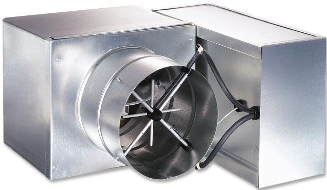
5 UNIQUE ELECTRIC HEAT DESIGN Model SDR-EH models are unique in that they correct common industry heating problems. Historically, heater elements placed downstream of a VAV damper have experienced two major problems: Elements fail prematurely due to hot spots resulting from an uneven air velocity profile over the heater face Heaters suffer rapid nuisance cycling of the contactors and elements because the airflow switch probe is located on the low pressure (downstream side) of the VAV damper Our unique electric heat VAV terminal, the SDR-EH, solves these problems. The heater elements are located midway between the air inlet and the damper. (See photo below.) This design provides uniform airflow over the face of the electric heater at all damper positions. Element life is extended, reducing repair cost and Inconvenience. With the heater elements located on the high pressure side of the VAV damper, the airflow pressure switch receives a reliable pressure signal even at minimum damper positions. This arrangement provides greater safety, as well as enhanced reliability. The SDR-EH design permits tremendous flexibility when selecting kw, voltage, phase, balanced or unbalanced circuits and method of control. The SDR-EH breaks new ground in single duct VAV electric heater design. The patented FlowStar sensor permits modulation to lower airflow levels than all other sensors in the industry. This minimizes the energy expended for heat in many applications. The FlowStar probe is visible in the inlet of the SDR-EH. The elements, partially removed for this photo, are midway between the inlet and the damper. ENVIRO-TEC 5

6 STANDARD CONSTRUCTION MODEL SDR The SDR terminal incorporates many standard features that are expensive options for other manufacturers. Mechanical lock construction ensures lowest possible casing leakage Roll formed inlet collar with integral stiffening ribs adds strength and rigidity Product label includes tagging, airflow and electrical information Electrical devices installed within a NEMA 1 enclosure, with single point power connection Galvanized steel casing withstands 125 hour salt spray test per ASTM B-117 Patented FlowStar airflow sensor (Patent #5,481,925) Insulation edge covered by metal no raw edges of insulation exposed to airstream Slip and drive discharge collar for quick field installation Solid composite damper shaft prevents condensation and breakage Units with electronic controls listed with ETL for safety compliance Low leakage damper incorporates closed cell foam gasket Mechanically fastened insulation for added security Self-lubricating bearing to reduce friction and air leakage 1/2 thick fiberglass insulation complying with UL 181, NFPA 90A, and ASTM C ENVIRO-TEC
 Factory piping packages")
7 OPTIONAL CONSTRUCTION MODEL SDR The SDR single duct terminal is available with many optional features to meet any project requirement. Factory control options: - Analog Electronic - DDC Electronic - Pneumatic For more information, see corresponding Control Selection Guides Double wall construction (not shown) Factory piping packages (refer to Piping Packages catalog) Mounting brackets (not shown) to accept all-thread hanging rods or wire hangers Scrim reinforced foil faced insulation meeting ASTM C1136 for mold, mildew and humidity resistance or 1/2 thick elastomeric closed cell foam insulation Low temperature construction for use in thermal storage applications, includes: - Thermally isolated primary air inlet - Composite damper shaft ENVIRO-TEC 7
8 STANDARD AND OPTIONAL FEATURES STANDARD FEATURES Construction AHRI 880 certified and labeled 22 gauge galvanized steel casing and valve 1/2 thick fiberglass insulation, mechanically fastened for added security Primary Air Valve Embossed rigidity rings Low thermal conductance damper shaft Position indicator on end of damper shaft Mechanical stops for open and closed position FlowStar center averaging airflow sensor Balancing tees Plenum-rated sensor tubing Hot Water Coil Designed and manufactured by ENVIRO-TEC AHRI 410 certified and labeled 1, 2, 3 or 4 rows Left or right hand connections Tested at a minimum of 450 PSIG under water and rated at 300 PSIG working pressure at 200 F Electrical cetl listed for safety compliance with UL 1996 NEMA 1 wiring enclosure Electric Heat cetl listed as an assembly for safety compliance Automatic reset primary and back-up secondary thermal limits Airflow switch Single point power connection Hinged electrical enclosure door Fusing per NEC OPTIONAL FEATURES Construction 20 gauge galvanized steel construction 3/4 and 1 insulation Foil faced scrim backed insulation 1/2 thick elastomeric closed cell foam insulation Double wall construction with 22 gauge liner Hot Water Coil Coil access plate for cleaning coil Electrical Toggle disconnect switch Primary and secondary transformer fusing Electric Heat Proportional SSR heater control Mercury contactors Door interlocking disconnect switches Controls Factory provided controls include: - Analog electronic - Pneumatic Piping Packages Factory assembled shipped loose for field installation 1/2 and 3/4, 2 way, normally closed, two position electric motorized valves Isolation ball valves with memory stop Fixed and adjustable flow control devices Unions and P/T ports Floating point modulating control valves High pressure close-off actuators 8 ENVIRO-TEC
9 APPLICATION AND SELECTION ACOUSTICAL CONCEPTS The focus on indoor air quality is also having an effect on proper selection of air terminal equipment with respect to acoustics. Sound. At the zone level, the terminal unit generates acoustical energy that can enter the zone along two primary paths. First, sound from the primary air valve can propagate through the downstream duct and diffusers before entering the zone (referred to as Discharge or Airborne Sound). Acoustical energy is also radiated from the terminal casing and travels through the ceiling cavity and ceiling system before entering the zone (referred to as Radiated Sound). To properly quantify the amount of acoustical energy emanating from a terminal unit at a specific operating condition (i.e. CFM and static pressure), manufacturers must measure and publish sound power levels. The units of measurement, decibels, actually represent units of power (watts). The terminal equipment sound power ratings provide a consistent measure of the generated sound independent of the environment in which the unit is installed. This allows a straight forward comparison of sound performance between equipment manufacturers and unit models. Noise Criteria (NC). The bottom line acoustical criteria for most projects is the NC (Noise Criteria) level. This NC level is derived from resulting sound pressure levels in the zone. These sound pressure levels are the effect of acoustical energy (sound power levels) entering the zone caused by the terminal unit and other sound generating sources (central fan system, office equipment, environment, etc.). The units of measurement is once again decibels; however, in this case decibels represent units of pressure (Pascals), since the human ear and microphones react to pressure variations. There is no direct relationship between sound power levels and sound pressure levels. Therefore, we must predict the resulting sound pressure levels (NC levels) in the zone based in part by the published sound power levels of the terminal equipment. The NC levels are totally dependent on the project specific design, architecturally and mechanically. For a constant operating condition (fixed sound power levels), the resulting NC level in the zone will vary from one project to another. AHRI 885. A useful tool to aid in predicting space sound pressure levels is an application standard referred to as AHRI Standard 885. This standard provides information (tables, formulas, etc.) required to calculate the attenuation of the ductwork, ceiling cavity, ceiling system, and conditioned space below a terminal unit. These attenuation values are referred to as the transfer function since they are used to transfer from the manufacturer s sound power levels to the estimated sound pressure levels resulting in the space below, and/or served by the terminal unit. The standard does not provide all of the necessary information to accommodate every conceivable design; however, it does provide enough information to approximate the transfer function for most applications. Manufacturers use different assumptions with respect to a typical project design; therefore, it is impossible to compare product performance simply by looking at the published NC values. GENERAL DESIGN RECOMMEND- ATIONS FOR A QUIET SYSTEM The AHU. Sound levels in the zone are frequently impacted by central fan discharge noise that either breaks out (radiates) from the ductwork or travels through the distribution ductwork and enters the zone as airborne (discharge) sound. Achieving acceptable sound levels in the zone begins with a properly designed central fan system which delivers relatively quiet air to each zone. Supply Duct Pressure. The primary factor contributing to noisy systems (including single duct applications) is high static pressure in the primary air duct. This condition causes higher sound levels from the central fan and also higher sound levels from the terminal unit, as the primary air valve closes to reduce the pressure. This condition is compounded when flexible duct is utilized at the terminal inlet, which allows the central fan noise and air valve noise to break out into the ceiling cavity and then enter the zone located below the terminal. Ideally, the system static pressure should be reduced to the point where the terminal unit installed on the duct run associated with the highest pressure drop has the minimum required inlet pressure to deliver the design airflow to the zone. Many of today s ENVIRO-TEC 9
10 APPLICATION AND SELECTION HVAC systems experience 0.5 w.g. pressure drop or less in the main trunk. For systems that will have substantially higher pressure variances from one zone to another, special attention should be paid to the proper selection of air terminal equipment. To date, the most common approach has been to select (size) all of the terminals based on the worst case (highest inlet static pressure) condition. Typically, this results in 80% (or higher) of the terminal units being oversized for their application. This in turn results in much higher equipment costs, but more importantly, drastically reduced operating efficiency of each unit. This consequently decreases the ability to provide comfort control in the zone. In addition, the oversized terminals cannot adequately control the minimum ventilation capacity required in the heating mode. A more prudent approach is to utilize a pressure reducing device upstream of the terminal unit on those few zones closest to the central fan. This device could simply be a manual quadrant type damper if located well upstream of the terminal inlet. In tight quarters, perforated metal can be utilized as a quiet means of reducing system pressure. This approach allows all of the terminal units to experience a similar (lower) inlet pressure. They can be selected in a consistent manner at lower inlet pressure conditions that will allow more optimally sized units. Inlet duct that is the same size as the inlet collar and as straight as possible will achieve the best acoustical performance. For critical applications, flexible duct should not be utilized at the terminal inlet. Zoning. On projects where internal lining of the downstream duct is not permitted, special considerations should be made to obtain acceptable noise levels. In these cases, a greater number of smaller zones will help in reducing sound levels. Where possible, the first diffuser takeoff should be located after an elbow or tee and a greater number of small necked diffusers should be utilized, rather than fewer large necked diffusers. The downstream ductwork should be carefully designed and installed to avoid noise regeneration. Bull head tee arrangements should be located sufficiently downstream of the terminal discharge to provide an established flow pattern downstream of the fan. Place diffusers downstream of the terminal after the airflow has completely developed. Downstream splitter dampers can cause noise problems if placed too close to the terminal, or when excessive air velocities exist. If tee arrangements are employed, volume dampers should be used in each branch of the tee, and balancing dampers should be provided at each diffuser tap. This arrangement provides maximum flexibility in quiet balancing of the system. High Quality VAV Terminal with Low Sound Levels IDEAL DUCT DESIGN Small Necked Diffusers Damper Located at Take-Off Minimum Required Inlet Static Pressure Multiple Branch Take-Offs Short Length of Non- Metallic Flexible Duct 10 ENVIRO-TEC
11 DIMENSIONAL DATA UNIT SIZE DIMENSIONS W H L A I X Y 4 10 [254] 10 [254] 11 [279] 10 1/2 [267] 3 7/8 [98] 8 3/4 [222] 8 3/4 [222] 5 10 [254] 10 [254] 11 [279] 10 1/2 [267] 4 7/8 [124] 8 3/4 [222] 8 3/4 [222] 6 10 [254] 10 [254] 11 [279] 6 1/2 [165] 5 7/8 [149] 8 3/4 [222] 8 3/4 [222] 8 12 [305] 10 [254] 11 [279] 6 1/2 [165] 7 7/8 [200] 10 3/4 [273] 8 3/4 [222] [356] 12 1/2 [318] 13 [330] 6 1/2 [165] 9 7/8 [251] 12 3/4 [324] 11 1/4 [286] [406] 15 [381] 13 [330] 6 1/2 [165] 11 7/8 [302] 14 3/4 [375] 13 3/4 [349] ] 17 1/2 [445] 17 1/2 [445] 6 1/2 [165] 13 7/8 [352] 18 3/4 [476] 16 1/4 [413] [610] 17 1/2 [445] 17 1/2 [445] 6 1/2 [165] 15 7/8 [403] 22 3/4 [578] 16 1/4 [413] [762] 17 1/2 [445] 11 [279] 8 [203] 28 1/4 [718] x 13 7/8 [352] 28 3/4 [730] 16 1/4 [413] [864] 17 1/2 [445] 11 [279] 8 [203] NOTES: 1. All dimensions are in inches [mm] with a tolerance of ±1/8 [3mm]. 2. Sizes 19 and 22 have rectangular inlet collar. 32 1/4 [819] x 15 7/8 [403] 32 3/4 [832] 16 1/4 [413] UNIT SIZE DIMENSIONS W H L A I 4 10 [254] 10 [254] 15 1/2 [394] 10 1/2 [267] 3 7/8 [98] 5 10 [254] 10 [254] 15 1/2 [394] 10 1/2 [267] 4 7/8 [124] 6 10 [254] 10 [254] 15 1/2 [394] 6 1/2 [165] 5 7/8 [149] 8 12 [305] 10 [254] 15 1/2 [394] 6 1/2 [165] 7 7/8 [200] [356] 12 1/2 [318] 17 1/2 [445] 6 1/2 [165] 9 7/8 [251] [406] 15 [381] 17 1/2 [445] 6 1/2 [165] 11 7/8 [302] ] 17 1/2 [445] 21 1/2 [546] 6 1/2 [165] 13 7/8 [352] [610] 17 1/2 [445] 21 1/2 [546] 6 1/2 [165] 15 7/8 [403] [762] 17 1/2 [445] 15 1/2 [394] 8 [203] [864] 17 1/2 [445] 15 1/2 [394] 8 [203] 28 1/4 [718] x 13 7/8 [352] 32 1/4 [819] x 15 7/8 [403] NOTES: 1. All dimensions are in inches [mm] with a tolerance of ±1/8 [3mm]. 2. Sizes 19 and 22 have rectangular inlet collar. ENVIRO-TEC 11
12 DIMENSIONAL DATA UNIT SIZE DIMENSIONS W H L I X Y A /8 8 3/4 8 3/4 10 1/2 [254] [254] [1041] [98] [222] [222] [267] /8 8 3/4 8 3/4 10 1/2 [254] [254] [1041] [124] [222] [222] [267] /8 8 3/4 8 3/4 6 1/2 [254] [254] [1041] [149] [222] [222] [165] /8 10 3/4 8 3/4 6 1/2 [305] [254] [1041] [200] [273] [222] [165] / /8 12 3/4 11 1/4 6 1/2 [356] [318] [1041] [251] [324] [286] [165] /8 14 3/4 13 3/4 6 1/2 [406] [381] [1041] [302] [375] [349] [165] / /8 18 3/4 16 1/4 6 1/2 [508] [445] [1041] [352] [476] [413] [165] / /8 22 3/4 16 1/4 6 1/2 [610] [445] [1041] [403] [578] [413] [165] 28 1/ /2 44 1/2 [718] x 28 3/4 16 1/4 1 1/2 [762] [445] [1130] 13 7/8 [730] [413] [38] [352] 34 [864] MODEL SDR - EH 17 1/2 [445] 44 1/2 [1130] 32 1/4 [819] x 15 7/8 [403] 32 3/4 [832] 16 1/4 [413] 1 1/2 [38] NOTE: All dimensions are in inches [mm] with a tolerance of ±1/8 [3mm]. MODEL SDR - SA UNIT SIZE * 22* DIMENSIONS W H A I X Y /2 3 7/8 8 3/4 8 3/4 [254] [254] [267] [98] [222] [222] /2 4 7/8 8 3/4 8 3/4 [254] [254] [267] [124] [222] [222] /2 5 7/8 8 3/4 8 3/4 [254] [254] [165] [149] [222] [222] /2 7 7/8 10 3/4 8 3/4 [305] [254] [165] [200] [273] [222] /2 6 1/2 9 7/8 12 3/4 11 1/4 [356] [318] [165] [251] [324] [286] /2 11 7/8 14 3/4 13 3/4 [406] [381] [165] [302] [375] [349] /2 6 1/2 13 7/8 18 3/4 16 1/4 [508] [445] [165] [352] [476] [413] /2 6 1/2 15 7/8 22 3/4 16 1/4 [610] [445] [165] [403] [578] [413] 28 1/ /2 8 [718] x 28 3/4 16 1/4 [762] [445] [203] 13 7/8 [730] [413] [352] 34 [864] 17 1/2 [445] 8 [203] 32 1/4 [819] x 15 7/8 [403] 32 3/4 [832] 16 1/4 [413] NOTE: All dimensions are in inches [mm] with a tolerance of ±1/8 [3mm]. 12 ENVIRO-TEC
13 AIRFLOW CALIBRATION FLOWSTAR CALIBRATION CHART (For dead-end differential pressure transducers) NOTE: Maximum and minimum CFM limits are dependent on the type of controls that are utilized. Refer to the table below for specific values. When DDC controls are furnished by others, the CFM limits are dependent on the specific control vendor that is employed. After obtaining the differential pressure range from the control vendor, the maximum and minimum CFM limits can be obtained from the chart above (many controllers are capable of controlling minimum setpoint down to.015 w.g.). For units with electric heat, a minimum 0.03 w.g. differential is required to satisfy the irflow switch in the electric heater. UNIT SIZE 400 SERIES (PNEUMATIC) STAN- DARD CONTROLLER 7000 SERIES ANALOG ELECTRONIC AIRFLOW RANGES (CFM) DDC CONSIGNMENT CONTROLS (See Notes Below) MIN. MAX. MIN. MAX. MIN. MAX. MIN. TRANSDUCER DIFFERENTIAL MAX. TRANSDUCER DIFFERENTIAL PRESSURE (IN. W.G.) PRESSURE (IN. W.G.) * < NOTES: 1. Minimum and maximum airflow limits are dependent on the specific DDC controller supplied. Contact the control vendor to obtain the minimum and maximum differential pressure limits (inches W.G.) of the transducer utilized with the DDC controller. 2. Maximum CFM is limited to value shown in General Selection Data. 3. * Electric heat will not operate below 0.03 w.g. differential pressure. ENVIRO-TEC 13
14 SELECTION DATA TERMINAL SIZE CFM Model SDR / SDR-SA MINIMUM Ps Model SDR-WC 1 Row Model SDR-WC 2 Row Model SDR DISCHARGE NOISE CRITERIA (NC) 0.5" Ps 1.0" Ps 3.0" Ps Model SDR-SA Model SDR Model SDR-SA Model SDR Model SDR-SA RADIATED NOISE CRITERIA (NC) 0.5" Ps 1.0" Ps 3.0" Ps Model SDR & SDR-SA Model SDR & SDR-SA Model SDR & SDR-SA NOTES: Min. DPs is the static pressure difference between the terminal inlet and discharge with the damper wide open. Performance data obtained from tests conducted in accordance with AHRI Standard 880. Dash (-) indicates NC level less than 20. NC values are calculated using attenuation values provided in appendix E of AHRI , as shown on the right. DISCHARGE OCTAVE BAND ATTENUATION VALUES Small Box (< 300 CFM) Medium Box ( CFM) Large Box (> 700 CFM) RADIATED OCTAVE BAND ATTENUATION VALUES Type 2 - Mineral Fiber Ceiling NC (sound pressure) levels predicted by subtracting appropriate values at right from published sound power levels (following pages). 14 ENVIRO-TEC
15 SOUND DATA TERMINAL SIZE DISCHARGE SOUND POWER DATA - MODEL SDR OCTAVE BAND NUMBER CFM 0.5" Ps 1.0" Ps 1.5" Ps 3.0" Ps Performance data obtained from tests conducted in accordance with AHRI Standard 880. Sound levels are expressed in decibels, db re: 1 x watts Duct end corrections included in sound power levels per AHRI Standard 880. Certified AHRI data is highlighted blue. Application data (not highlighted blue) is outside the scope of the certification program. ENVIRO-TEC 15
16 SOUND DATA TERMINAL SIZE RADIATED SOUND POWER DATA - MODEL SDR OCTAVE BAND NUMBER CFM 0.5" Ps 1.0" Ps 1.5" Ps 3.0" Ps Performance data obtained from tests conducted in accordance with AHRI Standard 880. Sound levels are expressed in decibels, db re: 1 x watts Certified AHRI data is highlighted blue. Application data (not highlighted blue) is outside the scope of the certification program. 16 ENVIRO-TEC
17 TERMINAL SIZE DISCHARGE SOUND POWER DATA - MODEL SDR - SA OCTAVE BAND NUMBER CFM 0.5" Ps 1.0" Ps 3.0" Ps Performance data obtained from tests conducted in accordance with AHRI Standard 880. Sound levels are expressed in decibels, db re: 1 x watts Duct end corrections included in sound power levels per AHRI Standard 880. ENVIRO-TEC 17
18 SOUND DATA TERMINAL SIZE RADIATED SOUND POWER DATA - MODEL SDR-SA OCTAVE BAND NUMBER CFM 0.5" Ps 1.0" Ps 3.0" Ps Performance data obtained from tests conducted in accordance with AHRI Standard 880. Sound levels are expressed in decibels, db re: 1 x watts 18 ENVIRO-TEC
19 AHRI RATINGS SIZE RATED AIRFLOW CFM MINIMUM OPERATING PRESSURE (IN. W.G.) Hz Octave Band Center Frequency Hz Octave Band Center Frequency Rated in accordance with AHRI Standard 880 Duct end corrections included in sound power levels per AHRI Standard 880. STANDARD RATINGS SOUND POWER LEVEL, db RE: 1 x WATTS RADIATED 1.5" WATER STATIC PRESSURE DISCHARGE ENVIRO-TEC 19

20 HOT WATER COIL DATA MODEL SDR-WC STANDARD FEATURES Coils are designed, manufactured, and tested by ENVIRO-TEC Aluminum fin construction with die-formed spacer collars for uniform spacing Mechanically expanded copper tubes leak tested to 450 PSIG air pressure and rated at 300 PSIG working pressure at 200 F Male sweat type water connections 1, 2, 3, and 4 row configurations OPTIONAL FEATURES Low pressure steam coils Multi-circuit coils for reduced water pressure drop Opposite hand water connections Bottom and top access plates for cleaning SELECTION PROCEDURE SDR-WC Hot Water Coil Performance Tables are based upon a temperature difference of 125 F between the entering water and the entering air. If this DT is suitable, proceed directly to the tables for selection. All pertinent performance data is tabulated. For Variable Air Volume Applications, the static pressure drop must be based on the maximum air volume. ENTERING WATER - AIR TEMPERATURE DIFFERENTIAL (DT) CORRECTION FACTORS DT FACTOR DT FACTOR The table above gives correction factors for various entering DT s (difference between EWT and EAT). Multiply MBH values obtained from selection tables by the appropriate correction factor above to obtain the actual MBH value. Air and water pressure drop can be read directly from the selection tables. The LAT and LWT can be calculated from the following fundamental formulas: LAT = EAT + BTUH LWT = EWT - BTUH x CFM 500 x GPM DEFINITION OF TERMS EAT Entering Air Temperature ( F) GPM Water Capacity (Gallons per Minute) EWT Entering Water Temperature ( F) MBH 1,000 BTUH LWT Leaving Water Temperature ( F) BTUH Coil Heating Capacity LAT Leaving Air Temperature (British Thermal Units per Hour) CFM Air Volume (Cubic Feet per Minute) 20 ENVIRO-TEC
21 MODEL SDR-WC - SIZES 4,5,6 AIRFLOW WATER FLOW LAT ( F) LWT ( F) CAPACITY (MBH) Water PD (FT.W.G.) Rate (CFM) Air PD (IN.W.G.) Rate (GPM) 1 Row 2 Row 1 Row 2 Row 1 Row 2 Row 1 Row 2 Row Row Row Row Row Row Row Row Row Row Row Row Row Row Row Row Row Rate (CFM) MODEL SDR-WC - SIZE 8 AIRFLOW WATER FLOW LAT ( F) LWT ( F) CAPACITY (MBH) Rate (GPM) Water PD (FT.W.G.) Air PD (IN.W.G.) 1 Row 2 Row 1 Row 2 Row 1 Row 2 Row 1 Row 2 Row Row Row Row Row Row Row Row Row Row Row Row Row Row Row Row Row Data is based on 180 F entering water and 55 F entering air at sea level. See selection procedure for other conditions. ENVIRO-TEC 21
22 HOT WATER COIL DATA MODEL SDR-WC - SIZE 10 AIRFLOW WATER FLOW LAT ( F) LWT ( F) CAPACITY (MBH) Water PD (FT.W.G.) Rate (CFM) Air PD (IN.W.G.) Rate (GPM) 1 Row 2 Row 1 Row 2 Row 1 Row 2 Row 1 Row 2 Row Row Row Row Row Row Row Row Row Row Row Row Row Row Row Row Row Rate (CFM) MODEL SDR-WC - SIZE 12 AIRFLOW WATER FLOW LAT ( F) LWT ( F) CAPACITY (MBH) Rate (GPM) Water PD (FT.W.G.) Air PD (IN.W.G.) 1 Row 2 Row 1 Row 2 Row 1 Row 2 Row 1 Row 2 Row Row Row Row Row Row Row Row Row Row Row Row Row Row Row Row Row Data is based on 180 F entering water and 55 F entering air at sea level. See selection procedure for other conditions. 22 ENVIRO-TEC
23 MODEL SDR-WC - SIZE 14 AIRFLOW WATER FLOW LAT ( F) LWT ( F) CAPACITY (MBH) Water PD (FT.W.G.) Rate (CFM) Air PD (IN.W.G.) Rate (GPM) 1 Row 2 Row 1 Row 2 Row 1 Row 2 Row 1 Row 2 Row Row Row Row Row Row Row Row Row Row Row Row Row Row Row Row Row Rate (CFM) MODEL SDR-WC - SIZE 16 AIRFLOW WATER FLOW LAT ( F) LWT ( F) CAPACITY (MBH) Rate (GPM) Water PD (FT.W.G.) Air PD (IN.W.G.) 1 Row 2 Row 1 Row 2 Row 1 Row 2 Row 1 Row 2 Row Row Row Row Row Row Row Row Row Row Row Row Row Row Row Row Row Data is based on 180 F entering water and 55 F entering air at sea level. See selection procedure for other conditions. ENVIRO-TEC 23
24 HOT WATER COIL DATA MODEL SDR-WC - SIZE 19 AIRFLOW WATER FLOW LAT ( F) LWT ( F) CAPACITY (MBH) Water PD (FT.W.G.) Rate (CFM) Air PD (IN.W.G.) Rate (GPM) 1 Row 2 Row 1 Row 2 Row 1 Row 2 Row 1 Row 2 Row Row Row Row Row Row Row Row Row Row Row Row Row Row Row Row Row Rate (CFM) MODEL SDR-WC - SIZE 22 AIRFLOW WATER FLOW LAT ( F) LWT ( F) CAPACITY (MBH) Rate (GPM) Water PD (FT.W.G.) Air PD (IN.W.G.) 1 Row 2 Row 1 Row 2 Row 1 Row 2 Row 1 Row 2 Row Row Row Row Row Row Row Row Row Row Row Row Row Row Row Row Row Data is based on 180 F entering water and 55 F entering air at sea level. See selection procedure for other conditions. 24 ENVIRO-TEC

25 ELECTRIC HEAT MODEL SDR-EH STANDARD FEATURES cetl listed as an assembly Single point power connection Primary auto-reset high limit Secondary high limit Airflow switch Hinged control panel Ni-Chrome elements Primary/secondary power terminations Fusing per NEC Wiring diagram and ETL label Available kw increments are as follows: 0.5 to 8.0 kw -.50 kw; 8.0 to 16.0 kw kw Above 16 kw kw OPTIONAL FEATURES Disconnect (toggle or door interlocking) PE switches Mercury and magnetic contactors Manual reset secondary limit Proportional control (SSR) 24 V control transformer SELECTION PROCEDURE With standard heater elements, the maximum capacity (kw) is obtained by dividing the heating (minimum) SCFM by 70. In other words, the terminal must have at least 70 SCFM per kw. In addition, each size terminal has a maximum allowable kw based upon the specific heater element configuration (i.e. voltage, phase, number of steps, etc.). Contact your representative or refer to the web-based Computer Selection Program Web- Select for design assistance. Heaters require a minimum of 0.07 w.g. downstream static pressure to ensure proper operation. For units with electric heat, a minimum 0.03 w.g. differential is required to satisfy the irflow switch in the electric heater. Selection Equations kw = SCFM x DT x 1.085* 3413 SCFM = DT = kw x 3413 DT x 1.085* kw x 3413 SCFM x 1.085* * Air density at sea level - reduce by for each 1000 feet of altitude above sea level. Calculating Line Amperage Single Phase Amps = kw x 1000 Volts Three Phase Amps = kw x 1000 Volts x 1.73 NOTES: 1. Electric heat will not operate below 0.03 w.g. differential pressure. ENVIRO-TEC 25
SDL Single-Duct, Low-Height, VAV Terminals
 SDL -Duct, Low-Height, VAV Terminals SDL -Duct, VAV Terminals: Fit more comfort in less space Owners SDL terminals offer the typical benefits provided by single-duct units, while performing at extremely
TSS Single-Duct VAV Terminals
 TSS Single-Duct VAV Terminals Model TSS construction features Standard Construction Mechanical-lock construction ensures lowest possible casing leakage Roll-formed inlet collar with integral stiffening
catalog SDL Single-Duct, Low-Height, VAV Terminals
 catalog SDL Single-Duct, Low-Height, VAV Terminals TABLE OF CONTENTS Features and Benefits.... 2 Controls.... 3 Construction Features... 4 Standard and Optional Features.... 5 Dimensional and Weight Data....
catalog SDL Single-Duct, Low-Height, VAV Terminals
 catalog SDL Single-Duct, Low-Height, VAV Terminals Catalog: ET130.13-EG2 (708) TABLE OF CONTENTS Single-Duct, Low-Height VAV Terminals Features and Benefits....................... 2 Controls..................................
catalog VFR Parallel Flow, Fan-Powered, 50/60 Hz VAV Terminals
 catalog VFR Parallel Flow, Fan-Powered, 50/60 Hz VAV Terminals TABLE OF CONTENTS Features and Benefits.... 2 Controls.... 4 Construction Features... 5 Standard and Optional Features.... 7 Application and
catalog CFR Series Fan-Powered, VAV Terminals
 catalog CFR Series Fan-Powered, VAV Terminals TABLE OF CONTENTS Features and Benefits...2 Construction Features...4 Standard And Optional Features...6 Application Selection...7 Application and Selection....8
Dual Duct Variable Air Volume Terminal (Model TDS)
") Product Bulletin Issue Date June 21st, 2005 Dual Duct Variable Air Volume Terminal (Model TDS) Model TDS terminals provide Variable Air Volume (VAV) control beyond the typical dual duct box. They are specifically
Product Bulletin Issue Date June 21st, 2005 Dual Duct Variable Air Volume Terminal (Model TDS) Model TDS terminals provide Variable Air Volume (VAV) control beyond the typical dual duct box. They are specifically
engineering guide TCS Series Fan-Powered, VAV Terminals
 engineering guide TCS Series Fan-Powered, VAV Terminals FORM 130.13-EG4 (908) TABLE OF CONTENTS Series Fan-Powered, VAV Terminals Features and Benefits....................... 2 Construction Features.......................
catalog CFRQ, Extra Quiet Series Flow, Constant Volume Fan Powered VAV Terminals
 catalog CFRQ, Extra Quiet Series Flow, Constant Volume Fan Powered VAV Terminals TABLE OF CONTENTS Features And Benefits... 2 Construction Features... 4 Standard & Optional Features... 6 Application And
catalog VFR Parallel Flow, Fan-Powered, VAV Terminals
 catalog VFR Parallel Flow, FanPowered, VAV Terminals TABLE OF CONTENTS Features and Benefits... 2 Controls... 4 Construction Features... 5 Standard and Optional Features... 7 Application and Selection....
catalog VFR Parallel Flow, Fan-Powered, 50/60 Hz VAV Terminals
 catalog VFR Parallel Flow, FanPowered, 50/60 Hz VAV Terminals TABLE OF CONTENTS Features and Benefits...2 Controls...4 Construction Features...5 Standard and Optional Features...7 Application and Selection....8
catalog VFL Parallel Fan-Powered, Low-Height, VAV Terminals
 catalog VFL Parallel FanPowered, LowHeight, VAV Terminals TABLE OF CONTENTS Features And Benefits...2 Construction Features...4 Standard And Optional Features...6 Application And Selection...7 Application
ATU PRODUCT CATALOG AIR TERMINAL UNITS FCI-600 CONSTANT VOLUME FAN TERMINAL UNIT Metal Industries, Inc.
 ATU PRODUCT CATALOG AIR TERMINAL UNITS FCI-600 CONSTANT VOLUME FAN TERMINAL UNIT 15 Metal Industries, Inc. BENEFITS: Fan powered terminals are typically used for heating and cooling of perimeter zones.
FAN POWERED TERMINAL UNITS
 Benefits: Fan powered terminals are typically used for heating and cooling of perimeter zones. Operating cost savings can be achieved through the use of waste heat recovery from the ceiling plenum and
FAN POWERED TERMINAL UNITS
 Benefits: Fan powered terminals are typically used for heating and cooling of perimeter zones. Operating cost savings can be achieved through the use of waste heat recovery from the ceiling plenum and
SINGLE DUCT AIR TERMINAL UNITS
 AIR terminal units AIR TERMINAL UNITS MODEL NUMBER LEGEND XXXXX XXX -XXXX Model TH TL THECO Inlet Size (04, 05, 06, etc.) Generation 5, 6, 7 The METALAIRE single duct terminal units are at the core of
SINGLE DUCT TERMINAL UNITS
 www.igcaire.com SINGLE DUCT TERMINAL UNITS Direct Digital Control, Pressure Independent FEATURES 22 Gauge Galvanized Steel Casing Construction with a 20 Gauge Casing Option that Provides Strength and Product
Variable Air Volume Dampers
 OVAV 2000 SERIES OPTIMA VAV DAMPERS Overview OPTIMA make Variable Air Volume (OVAV) box is a part of an Air Conditioning system. It is located inside the duct work. VAV Dampers are designed to control
FAN POWERED SERIES FCI-600 CONSTANT VOLUME FAN TERMINAL UNIT SPECIFIABLE FEATURES
 FAN TERMINAL UNIT SPECIFIABLE FEATURES Galvanized steel casing, mechanically sealed for low leakage construction NEMA TYPE 1 rated hinged control enclosure with standoff to prevent penetration of casing
Catalog Air Terminal Units. Models MQTH, MQFCI and MQFVI. Model MQTH. Model MQFCI. Model MQFVI
 Air Terminal Units Models MQTH, MQFCI and MQFVI Catalog 903-1 Model MQTH Model MQFCI Model MQFVI Table of Contents Single Duct Air Terminal Units.... 3 Introduction....3 MQTH-500 Single Duct Air Terminal
Product Data. Features/Benefits. 35K Bypass Terminal. 110 to 4400 cfm
 Product Data 35K Bypass Terminal 110 to 4400 cfm Carrier s 35K Series bypass terminals offer: 20-gage, galvanized steel casing construction 1/2-in. thick, dual density fiberglass insulation meeting NFPA
500-YH SINGLE DUCT AIR TERMINAL UNIT FORM EG1 (1101)
") 500-YH SINGLE DUCT AIR TERMINAL UNIT FORM 130.12-EG1 (1101) Table of Contents General Description.......................................................................3 500-YH Features........................................................................4-5
500-YH SINGLE DUCT AIR TERMINAL UNIT FORM 130.12-EG1 (1101) Table of Contents General Description.......................................................................3 500-YH Features........................................................................4-5
500-YVI PARALLEL FAN-POWERED AIR TERMINAL UNIT FORM EG3 (404)
") 500-YVI PARALLEL FAN-POWERED AIR TERMINAL UNIT Table of Contents Introduction...3 500-YVI Features...4-5 Dimensional Data...6-7 ARI Rating Points...8 Statement of Standard Test Conformity...8 Motor Amperage
500-YVI PARALLEL FAN-POWERED AIR TERMINAL UNIT Table of Contents Introduction...3 500-YVI Features...4-5 Dimensional Data...6-7 ARI Rating Points...8 Statement of Standard Test Conformity...8 Motor Amperage
Product Data. Features/Benefits. 35E Single Duct Terminal Units for Variable Air Volume Systems. Nominal 45 to 7100 cfm
 Product Data 35E Single Duct Terminal Units for Variable Air Volume Systems Nominal 45 to 7100 cfm Single duct variable air volume (VAV) terminal units provide: 22-gage galvanized steel, unit casing lined
B. Base occupied space sound level estimates on ARI 885. C. Terminal heating coils shall conform to ARI 410.
 PART 1 - GENERAL 1.01 Purpose: A. This standard is intended to provide useful information to the Professional Service Provider (PSP) to establish a basis of design. The responsibility of the engineer is
500-YCI SERIES FAN-POWERED AIR TERMINAL UNIT FORM EG2 (404)
") 500-YCI SERIES FAN-POWERED AIR TERMINAL UNIT Table of Contents General Information...3 500-YCI Features...4-5 Dimensional Data...6-7 ARI Rating Points...8 Statement of Standard Test Conformity...8 Motor
500-YCI SERIES FAN-POWERED AIR TERMINAL UNIT Table of Contents General Information...3 500-YCI Features...4-5 Dimensional Data...6-7 ARI Rating Points...8 Statement of Standard Test Conformity...8 Motor
FDCLP2 Constant Volume Series Flow, Low Profile
 The Price low profile series fan powered terminal unit is an ideal product for use in typical series fan powered applications with limited ceiling space. The is designed for constant air volume applications,
IAQ. Model AVC. SINGLE DUCT VAV Model AVC
 NON FAN POWERED UNITS SINGLE DUCT VAV Model AVC Model AVC The Carnes Model AVC is available as a basic control unit with open end discharge, with an optional multi-discharge adapter module, or sound attenuator
FAN TERMINAL UNITS Constant Volume (Series Flow), Standard Design
, Standard Design") FAN TERAL UNITS Constant Volume (Series Flow), Standard Design Models ACF w/o Coil ACW w/hot Water Coil ACE w/electric Coil The Carnes constant volume fan terminal unit provides constant air volume to
FAN TERAL UNITS Constant Volume (Series Flow), Standard Design Models ACF w/o Coil ACW w/hot Water Coil ACE w/electric Coil The Carnes constant volume fan terminal unit provides constant air volume to
Product Data. 35J Single-Duct Retrofit Terminal Units for Variable Air Volume Systems. 40 to 3700 cfm
 Product Data 35J Single-Duct Retrofit Terminal Units for Variable Air Volume Systems 40 to 3700 cfm The 35J retrofit terminal units offer: Unit casing of 22-gage galvanized steel construction (optional
Laboratory Room Single Duct Supply Air Terminal
 Technical Specification Sheet Document No. 149-319A June 24th, 2010 Laboratory Room Single Duct Supply Air Terminal Features Figure 1. Laboratory Room Single Duct Supply Air Terminal. The APOGEE Automation
High Performance Fan Coils FCHG Genesis Series Horizontal
 Dimensional Data 5 7 /8 (150) D 14 (356) 2 (51) Diverter - Slides Into Discharge Ductwork Optional: Second Drain Pan Connection E Coil Section X Dimensional Data - IP (in.) / SI [mm] Unit Fan Outlet Duct
IAQ. ROUND DUCT RETROFIT Model ARR
 Non Fan Powered Units ROUND DUCT RETROFIT Model ARR IAQ External Insulation Standard The Carnes Model ARR offers low pressure drop, low sound levels, and valve characteristics which create stable control
IAQ. Model AVW. SINGLE DUCT w/hot WATER HEAT Model AVW
 SINGLE DUCT w/hot WATER HEAT Model AVW Model AVW The Carnes Model AVW is available as a basic control unit with hot water reheat and open end discharge, with an optional sound attenuator module, and optional
SINGLE DUCT AIR TERMINAL UNITS
 SINGLE DUCT AIR terminal units SINGLE DUCT AIR TERMINAL UNITS MODEL NUMBER LEGEND XXXXX XXX -XXXX Model TH TL THECO Inlet Size (04, 05, 06, etc.) Generation 5, 6, 7 The METALAIRE single duct terminal units
SECTION AIR TERMINAL UNITS
 SECTION 23 36 00 AIR TERMINAL UNITS PART 1 - GENERAL 1.1 SUMMARY A. Section includes constant volume terminal units, variable volume terminal units, dual duct terminal units, fan powered terminal units,
VAV TERMINAL UNIT KYODO-ALLIED TECHNOLOGY PTE LTD
 VAV TERMINAL UNIT KYODO-ALLIED TECHNOLOGY PTE LTD R CONTENTS MODEL: KYODO / KYODO-R... 1 INTRODUCTION... 1 APPLICATION... 1 VARIABLE AIR VOLUME SYSTEM... 1 FEATURES... 2 MATERIALS... 3 AIR VOLUME CONTROL
PH SERIES SINGLE DUCT ATU PERFORMANCE DATA
 PH SERIES SINGLE DUCT ATU PERFORMAE DATA The Performance Aire PH Series is the simplest and most widely used VAV terminal unit. Its basic components are an insulated sheet metal box, round inlet damper,
RETROFIT TERMINAL UNITS
 GENERAL PROUCT OVERVIEW Retrofit Terminal s Convert Constant Air Volume Systems to Variable Air Volume. Convert Constant Volume ual uct Systems to Variable Air Volume. Convert Multizone Systems to Variable
Dual Duct Terminal Units DPS, DDS Series, DPQ, DDQ Series, DPV, DDV Series, DPM, DDM Series, DPUQ, DDUQ Series
 DPS, DDS Series, DPQ, DDQ Series, DPV, DDV Series, DPM, DDM Series, DPUQ, DDUQ Series Product Key UQ Ultra Quiet Product Selection Checklist 1] Select Unit Inlet Size based on control and acoustic parameters.
University of Delaware
 SECTION 23 36 00 _ SUMMARY PART 1 GENERAL 1.1 SUMMARY A. Section Includes: 1. Constant/Variable volume supply terminal units. 2. Fan powered terminal units. 3. Exhaust valves B. Related Sections: Section
SBH / SBV Sales Guide BLOWER-COILS HORIZONTAL AND VERTICAL
 SO TOUGH, WE GUARANTEE IT. SBH / SBV Sales Guide BLOWER-COILS HORIZONTAL AND VERTICAL SBH SBV www.superiorrex.com SO TOUGH, WE GUARANTEE IT! www.superiorrex.com SBH / SBV Series: CONSTRUCTION FEATURES
Variable Air Volume Distribution Units CII, September 1 st, Home
 Variable Air Volume Distribution Units CII, September 1 st, 2010 1 VAV It s All About Measuring Airflow Accurate air flow measurement allows you to: Provide the absolute minimum air flow needed for ventilation.
SINGLE DUCT TERMINAL UNITS 30X/HQX SERIES
 30X/HQX SERIES 30X SERIES EXHUST 30HQX SERIES EXHUST HOSPITL GRDE QUIET TYPE WITH DISSIPTIVE SILENCER PRODUCT OVERVIEW Nailor Single Duct Exhaust Terminal Units are used to modulate exhaust flow from an
HOW TO SPECIFY SDV UNITS
 HOW TO SPECIFY SDV UNITS MODEL UNIT CONFIG LINER CASING OPTIONS CONST. SIDE INLET SIZE DISCHARGE OPTIONS CONTROL TYPE UNIT ACCESSORIES HEAT kw ELECTRIC HEAT ACCESSORIES SCR HEAT ACCESSORIES SDV 0 - Standard
Fan Powered Terminal Units FPV, FDV Series Variable Volume Parallel Flow
 Recommended Air Volume Ranges CP 101 Unit Size L/s Min.* L/s Max. cfm Min.* cfm Max. 6 31 212 66 450 8 62 378 132 800 10 104 637 221 1350 12 146 991 310 2100 14 207 1416 439 3000 16 268 1888 568 4000 CP
Variable Air Volume (VAV) Pressure Independent Control
 Pressure Independent Control") VAV Terminal Units Asli Variable Air Volume (Vav) Terminal Units are volume flow rate controller for supply air on variable air volume system. These units are designed to control the airflow rate of conditioned
VAV Terminal Units Asli Variable Air Volume (Vav) Terminal Units are volume flow rate controller for supply air on variable air volume system. These units are designed to control the airflow rate of conditioned
Fan - Powered Terminal Unit Series Flow
 5/22/M/1 Fan - Powered Terminal Unit Series Flow Type TFP Trox (Malaysia) Sdn Bhd 20 Persiaran Bunga Tanjung 1 Senawang Land Industrial Park 70400 Seremban Negeri Sembilan Darul Khusus Malaysia Telephone
Laboratory Room Single Duct Supply Air Terminal
 Technical Specification Sheet Document No. 149-319P25 July 28, 2017 Laboratory Room Single Duct Supply Air Terminal Features Figure 1. Laboratory Room Single Duct Supply Air Terminal. The Laboratory Room
Horizontal and Vertical BELT DRIVE AIR HANDLING UNITS
 Horizontal and Vertical BELT DRIVE AIR HANDLING UNITS TABLE OF CONTENTS H & V Features and Benefits...4 Coil and Filter Data, Static Pressure Data...7 Electric Resistance Heat Section...8 Coil Information
LMHS BASIC UNIT NO CONTROLS
 JOB NAE ARCHITECT ENGINEER CONTRACTOR OCATION SUBITTA SHEET Form Number TS0000.10 Effective Date 6/08 Replaces Form TS0000.9 BASIC UNIT NO CONTROS CHARTED 'A' DIENSION INCUDES INET ADAPTER PROVIDED ON
NORTHWESTERN UNIVERSITY PROJECT NAME JOB # ISSUED: 03/29/2017
 SECTION 23 3600 - AIR TERMINAL DEVICES PART 1 - GENERAL 1.1 SUMMARY A. Section Includes: 1. Fan-powered air terminal units/devices. 2. Shut off air terminal units/devices. 3. Dual duct terminal units/devices.
D2-2. Table of Contents RETROFIT/BYPASS TERMINAL UNITS
 D2 RETROFIT/YPASS TERMINA UNITS Table of Contents RETROFIT/YPASS TERMINA UNITS RVE This retrofit terminal unit is designed to convert high pressure mechanical constant volume systems to low pressure variable
HORIZONTAL HIGH CAPACITY FAN COIL UNITS DUCTED
 Direct Drive, Draw-through Design Model Series 3FH Filter 1" (2) throwaway (standard) 2" (1) MERV 8 or MERV 13 pleated (optional) Multiple coil options: 3, 4,, 6 row cooling or heating coils 1 or 2 row
TVS/R FAN COIL UNITS HI-RISE, VERTICAL
 TVS/R FAN COIL UNITS HI-RISE, VERTICAL TVRM TVRP Riser TVRS TVSE TVSM TVSR TVSS Redefine your comfort zone. www.titus-hvac.com Redefine your comfort zone www.titus-hvac.com Model TVS/R: CONCEALED, HI-RISE
RBV Sales Guide FAN COIL UNITS FLOOR-MOUNTED, VERTICAL
 RBV Sales Guide FAN COIL UNITS FLOOR-MOUNTED, VERTICAL RBVS RBVR RBVC www.superiorrex.com RBV Series: LOW POWER CONSUMPTION, ACCESSIBLE AND FLEXIBLE Owners Owners can choose between a standard or elevated
Fan-Powered Parallel
 Table of Contents Model Number Description 76 Selection Procedure 77-79 General Data Setting Guidelines 80 Performance Data Pressure Requirements 81 Performance Data Fan Curves 82-85 Performance Data Hot
Product Data. AXIS 45X, 45U, 42K, 35BF Access Floor Terminal Units for Variable Air Volume Systems
 Product Data AXIS 45X, 45U, 42K, 35BF Access Floor Terminal Units for Variable Air Volume Systems 45UC 35BF-R 42KC 45XC 35BF-D Features/Benefits Access Floor Systems can provide flexibility and economic
single / dual duct terminals
 PERFORANCE DATA RECOENDED PRIARY AIR CF RANGES / ALL TERINALS Control Types: PESV / Pneumatic AESV / Analog Electronic DESV / Digital Electronic QUICK SELECTION PROCEDURE 1. Select unit inlet size based
RAV Sales Guide FAN COIL UNITS HI-RISE, VERTICAL
 RAV Sales Guide FAN COIL UNITS HI-RISE, VERTICAL RAVS RARM RARS RAVE RAVM RAVL RARP RISER www.superiorrex.com RAV Series: VERTICAL HI-RISE CONCEALED SO TOUGH, WE GUARANTEE IT! www.superiorrex.com Model
VAV RETROFIT/BYPASS TERMINAL UNITS TABLE OF CONTENTS RETROFIT/BYPASS TERMINAL UNITS. E-2 Excellence in Air Distribution MODEL RVE MODEL KLB MODEL SVE
 TALE OF CONTENTS RETROFIT/YPASS TERMINAL UNITS RVE This retrofi t terminal unit is designed to convert high pressure mechanical constant volume systems to low pressure variable volume systems and also
Submittal 30 [762] 36 [914] 40 [1016] 50 [1270] 60 [1524] 70 [1778]
![Submittal 30 [762] 36 [914] 40 [1016] 50 [1270] 60 [1524] 70 [1778]](/thumbs/85/92244975.jpg "Submittal 30 [762] 36 [914] 40 [1016] 50 [1270] 60 [1524] 70 [1778]") FCU-THBP-1.0 08-22-18 THBP Horizontal Low Profile Plenum Return Top View (Drain Pan Omitted) Bottom View Front View Left hand unit shown. All dimensions are inches [millimeters]. Side View Unit Size A
FCU-THBP-1.0 08-22-18 THBP Horizontal Low Profile Plenum Return Top View (Drain Pan Omitted) Bottom View Front View Left hand unit shown. All dimensions are inches [millimeters]. Side View Unit Size A
Submittal. Front View Side View
 RBHO Horizontal Low Profile Concealed Free Return Submittal FCU-RBHO-1.0 07-25-18 Top View (Drain Pan Omitted) Bottom View Front View Side View Left hand unit shown. All dimensions are inches [millimeters].
MODELS TSX AND TSX-S SINGLE DUCT ROUND AIR TERMINALS
 MODELS TSX AND TSX-S SINGLE DUCT ROUND AIR TERMINALS INSTALLATION OPERATION & MAINTENANCE New Release Form 130.13-NOM4 (908) In conjunction with the use of these instructions, obtain and refer to the construction,
FN Fan-Coil Units High-Performance, Horizontal
 FN Fan-Coil Units High-Performance, Horizontal Model FNX Exposed-Cabinet Dimensional Data Notes: 1. All dimensions are in inches [mm] and are +/- 1/8" [3 mm]. Metric values are soft conversions. 2. See
FS Fan-Coil Units Hi-Rise, Vertical
 FS Fan-Coil Units Hi-Rise, Vertical FSC Concealed Dimensional Data 4-PIPE 2-PIPE TOP VIEWS Page Trims Short (5/8") Here! SIDE VIEW FRONT VIEW Dimensions Unit Size A B Single/Double Supply C D E 03 & 04
Product Data. Features/Benefits. 45J,M,K,N,Q,R Standard, Quiet, and Low Profile Fan Powered Variable Air Volume Terminals
 Product Data 5J,M,K,N,Q,R Standard, Quiet, and Low Profile Fan Powered Variable Air Volume Terminals 90 to 3900 Cfm Series Fan Box 5J,K,Q Parallel Fan Box 5M,N,R 5J,M 5K,N 5Q,R The 5J,M,K,N,Q,R units were
MODELS SGX AND SSX SINGLE DUCT ROUND AIR TERMINALS
 BY JOHNSON CONTROLS INSTALLATION OPERATION & MAINTENANCE MODELS SGX AND SSX SINGLE DUCT ROUND AIR TERMINALS New Release Form ET130.13-NOM4 (908) In conjunction with the use of these instructions, obtain
PERFORMANCE DATA Intermittent Volume (Parallel Flow), Standard Design
, Standard Design") FAN CURVES vs FAN SIZE A AS 05, 06, 07 1/6 H.P. Motor FAN SIZE B AS 06, 07, 08 1/6 H.P. Motor NOTES: 1. External Static Pressure (ESP) consists of down stream ductwork, coils, flex, duct, etc. 2. Pressure
FAN CURVES vs FAN SIZE A AS 05, 06, 07 1/6 H.P. Motor FAN SIZE B AS 06, 07, 08 1/6 H.P. Motor NOTES: 1. External Static Pressure (ESP) consists of down stream ductwork, coils, flex, duct, etc. 2. Pressure
SPV / SDV Series SINGLE DUCT TERMINAL UNITS
 SPV / SDV Series SINGLE DUCT Price single duct terminal units are designed to control the airflow rate of conditioned air into an occupied space with minimal pressure drop and low noise levels. An extensive
Sound Application Guide: Description and Ratings
 Sound Application Guide: Description and Ratings AHRI SOUND STANDARD: DESCRIPTION AND RATINGS Table of Contents Overview..........................................................................4 AHRI
AIR ZONE INTERNATIONAL MIXED-FLOW AIR COLUMN UNIT
 ZONE INTERNATIONAL MIXED- COLUMN UNIT 5220 TED ST. HOUSTON, TEXAS 77040 (713) 460-4040 FAX (713) 460-4050 WWW.ZONEINC.COM ZONE INTERNATIONAL MIXED- COLUMN UNIT T DUCT COLLAR INLET (A x B) PRIMARY RETURN
CCS Zone/Bypass Damper Assembly
 Code No. LIT-1900539 Issued July 15, 2011 UZR-xx-x, UBR-xx-x, UZD-0xxX0xx-x, UBD-0xxX0xx-x CCS Zone/Bypass Damper Assembly Description The Commercial Comfort System (CCS) Zone/Bypass Damper are zone control
Complete HVAC Capability
 Air Handling Units Brochure 1110 January 2006 Complete HVAC Capability MEA Horizontal Draw-Thru to Size 65 Vertical Draw-Thru to Size 50 1000 to 60,000 CFM Forward Curved or Airfoil Wheels Inlet Vane Option
WAC Air Curtains Technical Guide
 TGWAC-2 WAC Air Curtains Technical Guide FOR WIND STOPPING, INSECT CONTROL, AND ENVIRONMENTAL SEPARATION IN COMMERCIAL AND INDUSTRIAL APPLICATIONS TABLE OF CONTENTS Introduction......................................................................2
The Premium Quality Fan Coil Units for Horizontal Application Hydronic or Electric Heat
 Producing Quality Heating & Cooling Equipment For Over 50 Years CEA SERIES CEILING EPOSED HORIZONTAL FAN COIL UNITS The Premium Quality Fan Coil Units for Horizontal Application Hydronic or Electric Heat
C2-2. Table of Contents DUAL DUCT TERMINAL UNITS
 C2 UA UCT TERINA UNITS Table of Contents UA UCT TERINA UNITS This unit features a compact design for variable volume applications where blending of hot and cold air is not required. T This unit features
FCVC Series VERTICAL FAN COILS
 VERTICAL FAN COILS The FCVC is designed for concealed, wall mounted installations with flexible heating/ cooling loads and minimal duct requirements. With a variety of options, such as fiber free insulation,
fan powered terminals
 PTFS-F, ATFS-F, DTFS-F / AIRFLOW VS. DOWSTREAM STATIC PRESSURE TFS-F Size B 650 600 550 450 350 250 200 1 1200 1100 600 TFS-F Size C 150 TFS-F Size D 2 TFS-F Size E 1 2600 1 1 1600 1 1 1 1200 1100 2 2
Product Data. Features/Benefits. 42BH System Fan Coil. 800 to 4000 Cfm
 Product Data 42BH System Fan Coil 800 to 4000 Cfm Satisfy All Your Design Requirements with Carrier s Versatile 42BH Fan Coil Unit A selection of 6 sizes covers capacities from 800 to 4000 cfm Choice of
Centrifugal Cabinet Fans Model BCF Belt Drive Low-Profile
 Centrifugal Cabinet s BCF Belt Drive Low-Profile May 2007 BCF Belt Drive Cabinet s Greenheck belt drive low-profile cabinet fans, BCF, are designed for efficiency and reliability in supply, exhaust or
Submittal DIMENSIONS SIZE FAN SIZE L W H C D E F G J K [406] [508] 25 [635] [406] 16 [406] 16 [406] 39-1/2 [1003] 44-1/2 [1130] 51 [1295] 59 [1499]
![Submittal DIMENSIONS SIZE FAN SIZE L W H C D E F G J K [406] [508] 25 [635] [406] 16 [406] 16 [406] 39-1/2 [1003] 44-1/2 [1130] 51 [1295] 59 [1499]](/thumbs/94/122284584.jpg "Submittal DIMENSIONS SIZE FAN SIZE L W H C D E F G J K [406] [508] 25 [635] [406] 16 [406] 16 [406] 39-1/2 [1003] 44-1/2 [1130] 51 [1295] 59 [1499]") BC--1.0 03-01-1 Belt Drive Blower Coil Unit, Basic Unit Discharge ARGT. 1 4. See page 1 for filter rack details. 5. Base rail is optional on he base unit. See page 13. Base rails must be used with mixing
BC--1.0 03-01-1 Belt Drive Blower Coil Unit, Basic Unit Discharge ARGT. 1 4. See page 1 for filter rack details. 5. Base rail is optional on he base unit. See page 13. Base rails must be used with mixing
Product Data. Features/Benefits. 45J,M,K,N,Q,R Standard, Quiet, and Low Profile Fan Powered Variable Air Volume Terminals.
 Product Data 45J,M,K,N,Q,R Standard, Quiet, and Low Profile Fan Powered Variable Air Volume Terminals 90 to 3900 Cfm 45J,M 45K,N 45Q,R The 45J,M,K,N,Q,R units were designed to maintain accurate temperatures
I Fan Powered Terminal Unit
 I Fan Powered Terminal Unit VARIABLE VOLUME PARALLEL FLOW Fan Powered Terminal Unit Variable volume parallel flow Product Overview Variable Volume/Parallel Flow Fan Powered Terminal Units Honeywell parallel
Centrifugal Inline Fans Models SQ-M and BSQ-M. Direct and Belt Drive
 Centrifugal Inline s Models SQ-M and BSQ-M Direct and Belt Drive July 2010 Centrifugal Inline Duct s Greenheck's model SQ-M and BSQ-M centrifugal square inline fans feature a unique combination of installation
Laboratory Exhaust Air Terminal
 Laboratory Exhaust Air Terminal Page 1 of 11 Figure 1. Laboratory Exhaust Air Terminal. The APOGEE Automation Laboratory Room Exhaust Air Terminal is an industrial grade, easy-to-install, prepackaged airflow
Centrifugal Cabinet Fans Model BCF. Belt Drive Low-Profile
 Centrifugal Cabinet s BCF Belt Drive Low-Profile November 204 BCF Centrifugal Cabinet Contents Standard Construction Features... 3 Options and Accessories... 4 Filter and Mixing Box Data... 5 Typical Installations...
Single-Duct. Table of Contents. Model Number Description SD 2 3. Service Model Number Description SD 4. Selection Procedure SD 5 6
 Table of Contents Model Number Description SD 2 3 Service Model Number Description SD 4 Selection Procedure SD 5 6 General Data Valve/Controller Airflow Guidelines SD 7 Performance Data Pressure Requirements
SPVQ / SDVQ Series QUIET SINGLE DUCT TERMINAL UNIT
 Patented SPVQ / SDVQ Series QUIET SINGLE DUCT TERMINAL UNIT In an era of increasing IAQ and noise concerns, this innovative product is specifically designed to meet the challenges headon. Certified assemblies
Direct Gas-Fired Heating
 Direct Gas-Fired Heating Model DG 800 to 15,000 cfm Up to 1,600,000 BTU/hr Optional Evaporative Cooling January 2005 PRODUCT FEATURES Model DG Direct Gas-Fired Make-Up Air Unit The Greenheck model DG is
FPV, FDV Series Variable Volume Parallel Flow
 Product Overview Variable Volume/Parallel Flow Fan Powered Terminal s With the variable volume model, the conditioned primary air does not pass through the fan. The primary air section and the recirculating
T VB FA N COIL U NIT S F LO OR -MOU NT E D, V E RT ICA L
 T VB FA N COIL U NIT S F LO OR -MOU NT E D, V E RT ICA L TVBA TVBC TVBF Redefine your comfort zone. www.titus-hvac.com Redefine your comfort zone www.titus-hvac.com Model TVB: LOW POWER CONSUMPTION, ACCESSIBLE
Centrifugal Cabinet Fans Model BDF. Belt Drive Duct Fan
 Centrifugal Cabinet s BDF Belt Drive Duct July 007 BDF Belt Drive Duct s Greenheck s Belt Drive Duct s, BDF, provide the industry s best performance and durability. BDF is carefully engineered for efficiency
Air Measuring Products AMD AMS IAQ
 Air Measuring Products AMD AMS IAQ January 1 2012 Air Measuring Products Why is outside air measurement important? There are many significant benefits to monitoring outside air volumes. By measuring the
SPD SQUARE PLAQUE DIFFUSER
 SQUARE PLAQUE DIFFUSER The (SPD) has a flush appearance, making it ideal for architecturally-conscience commercial spaces, and provides industry-leading low pressure drop and sound generation with a 360
UNIFIED FACILITIES GUIDE SPECIFICATIONS
 USACE / NAVFAC / AFCEC / NASA UFGS-23 36 00.00 40 (May 2016) ----------------------------------- Preparing Activity: NASA Superseding UFGS-23 36 00.00 40 (February 2011) UFGS-23 36 00 (November 2010) UNIFIED
FW and FL Fan-Coil Units Floor-Mounted, Vertical STANDARD AND LOW PROFILE
 FW and FL Fan-Coil Units Floor-Mounted, Vertical STANDARD AND LOW PROFILE Low Power Consumption, Accessible, & FW and FL Fan-Coil Design Features Owners Owners can choose between a standard height (FW)
YCCS Zone/Bypass Damper Assembly
 YCCS Zone/Bypass Damper Assembly UZR-xx-x, UBR-xx-x, UZD-0xxX0xx-x, UBD-0xxX0xx-x The York Commercial Comfort System (YCCS) Zone/Bypass Damper are zone control and pressure control devices that include
VIFB Coil Technical Guide
 TGVIFB-5 VIFB Coil Technical Guide VERTICAL TUBE INTEGRAL FACE AND BY-PASS HEATING COILS FOR AIR PREHEATING Since 1875, the L.J. Wing Company has been a leader in providing innovative solutions for difficult
 Issue 4 (Record Only) Job #: Innovent Submittal Date: October 30, 2012 Project: Location: Columbus, OH Innovent Job #: Submittal Issue: 4 (Record Only) Engineer: Contractor: Tag Innovent Model # AHU-BG-01