FAN POWERED TERMINAL UNITS
|
|
|
- Wesley Stone
- 6 years ago
- Views:
Transcription
1

2 Benefits: Fan powered terminals are typically used for heating and cooling of perimeter zones. Operating cost savings can be achieved through the use of waste heat recovery from the ceiling plenum and from reduced central fan HP. This coupled with a relatively low impact on installation costs are reasons for the widespread application of fan powered terminal units. terminal units TERMINAL UNITS Function Fan Operation Series fan Powered Terminal Units In the series fan powered terminal, the primary air valve and fan are in the primary airstream, and are sized for the cooling load. The fan runs continuously during both heating and cooling modes. The volume of supply air remains constant at all times resulting in better diffuser performance and constant noise levels. Series Terminal Constant volume Continuous. Runs under heating and cooling in occupied and unoccupied modes. Both parallel and series fan powered terminals have a damper to modulate primary cooling air and a fan/motor assembly that draws return air from the ceiling plenum. The difference in the configuration and operation of these terminals is illustrated on these pages. Parallel Fan Powered Terminal Units In the parallel fan powered terminal, the primary air valve is sized for the cooling airflow just as in single duct terminals. The fan section is outside of the primary airstream and typically runs only in the heating mode. It is typically sized for 50% of the maximum primary airflow which can result in lower noise levels, lower unit first costs, and reduced energy usage when compared to a series fan powered terminal due to the fan not being on at all times with fan being energized only during heating mode. Parallel Terminal Variable volume Intermittent. Typically runs only under heating mode. Operation of Terminal Terminal Fan Sizing Central Fan Sizing Constant volume, variable temperature at all times. Supplemental heat raises supply temperature in stages. For design airflow heating or cooling, whichever is greater at required downstream static pressure. Static pressure needed to overcome volume damper only. Variable volume, constant temperature during cooling. Constant volume variable temperature during heating. Fan and supplemental heat raise supply temperature in stages. For design heating load at reduced downstream static pressure (typically 50% of cooling cfm). Static pressure needed to overcome volume damper, heating coil, downstream duct, and diffusers. MODEL NUMBER LEGEND Example: FCI C5 614C-900B FXX XX XXXX -XXXX C Series Unit V Parallel Unit Case Size (C1, C2, C3, etc.) I Improved Q Ultra Quiet L Low Profile Inlet Size (04, 05, 06, etc.) Generation 5, 6, 7 Motor Voltage A 1 C 277 F Terminal Type: 8 FVI, FVL 9 FCI, FCL, FCQ Control Sequence: 00B No Controls 05 DDC 6 Analog 1 Pneumatic A 1/24 Transformer Voltage C 277/24 Transformer Voltage F 8/24 Transformer Voltage N No Transformer E Electric Heat FP 2 Metal Industries, Inc. For complete product specifications and submittal data, visit us at
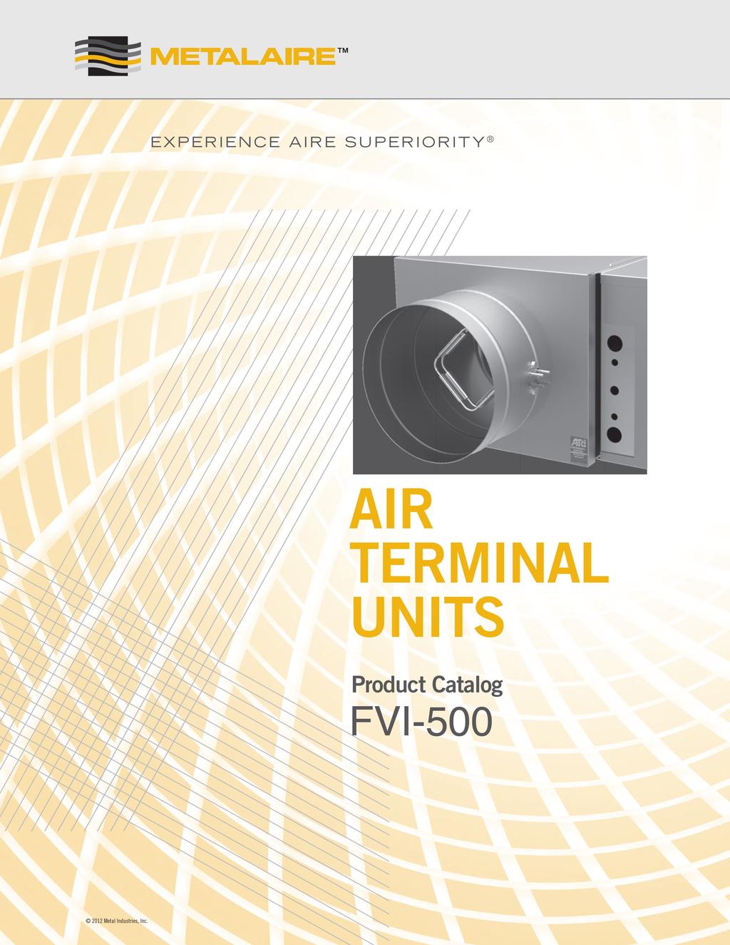
3 TYPES OF TERMINAL UNITS FCI-600 SERIES UNIT In a constant volume (or series) fan powered terminal, the fan runs continuously. Both primary and induced air are discharged through the fan. FVI-500 UNIT In a variable volume (or parallel) terminal unit, the fan runs only when heating is required. In cooling, the unit functions the same as a single duct VAV terminal. terminal units Certification and Standards Units tested per ANSI/ASHRAE Standard 130. All model sizes certified in accordance with AHRI 880 certification program. ETL listed to meet requirements of UL 1995 and CSA 236. Dual-density fiberglass insulation meets UL 181 and NFPA 90A requirements. Insulation meets ASHRAE 62.1 requirements for resistance to mold growth and erosion. Options Energy-efficient electronically commutated motor (ECM). SSR controlled electric heater. Mercury contactors for quiet operation of the electric heater. Inlet attenuator for quiet applications. 12 Metal Industries, Inc. FP 3
4 FAN TERMINAL UNIT specifiable Features Galvanized steel casing, mechanically sealed for low leakage construction Nema 1 rated hinged control enclosure with standoff to prevent penetration of casing Single speed high efficiency PSC motor with SCR motor speed control Continuous welded primary inlet duct to minimize leakage with 3 stiffening beads for added rigidity Damper construction of double layer 18 gauge equivalent with integral blade seal All metal constructed inlet flow sensor with extra balancing taps Single point electrical connection Gasketed back draft damper door to minimize leakage in cooling mode INDEX OF SECTIONS page Dimensional Data 94 AHRI Data / Certification and Standards 102 Acoustic Performance 103 Motor Data / Damper Leakage 117 Minimum Pressures Chart 118 Coil Selection 119 Accessories and Components Shipping Weights / Induction Filter Sizes 123 Available Controls 128 Fan Performance Curves Metal Industries, Inc. FP 91
5 FAN TERMINAL UNIT MetalAire s model FVI-500 parallel fan-powered terminal unit is designed to provide superior comfort to zones by intermittent parallel fan operation. Conditioned primary air is varied during cooling while the fan cycles on during heating. Parallel fan-powered terminal units allow for recovery of waste heat from the return plenum and a potential reduction in central fan energy, thereby lowering operating costs. In the heating mode with the fan energized, parallel fan-powered terminal units improve air circulation through better diffuser performance. The primary air does not pass through the fan. The primary function of the METALAire model FVI-500 parallel fan-powered terminal unit is to deliver variable volume, constant temperature primary air to the space in the cooling mode. The volume of supply air is varied in response to a control signal. In the heating mode, with the fan energized, the terminal unit mixes conditioned air and plenum air in response to a control signal to supply constant volume, variable temperature supply air into the space. Supplemental heating is available in both electric heat and hot water coils if plenum heat is insufficient. METALAire model FVI-500 parallel fan-powered terminal units are available with a wide range of control options to suit any application. These include pneumatic, analog electronic, electric, factory provided commissioned direct digital control (DDC) or factory mounted field supplied (DDC) controls. With the demands of today s building designs to reduce energy in smaller mechanical spaces, the METALAire model FVI-500 parallel fan-powered terminal unit is the perfect choice. Standard Features Available in 7 casing sizes to handle cfm. 22 ga. galvanized steel casing, mechanically sealed, low leakage construction. Damper constructed of double layer of 24 ga. galvanized steel with sandwiched flexible gasket to provide tight seal (<1% at 3" static pressure). Factory calibrated controls per each job requirement. MetalAire multi-quadrant averaging flow sensor provides highly accurate +/- 5% flow readings after certified balancer has balanced terminal. Easy access, steel balancing taps. Energy efficient six pole single speed PSC motors with adjustable SCR solid state fan speed controllers are standard. Electronically Commutated Motors (ECM) available as an option. Available motor voltages of 1,277 and (50/60 HZ) External control cabinet with offset mounting plate as standard. Single point electrical connections. 3-beaded primary inlet connection tube for added rigidity and secure flex duct connections. Round inlets available in sizes 6" through ". 1" thick, dual density (1.5lb/ft 3 min.) fiberglass insulation with edges coated. Meets NFPA 90A and UL 181. (1/2" thick insulation standard on FVL-600.) Rectangular flanged discharge with optional slip and drive cleat duct connection. Large Bottom access panel provides access to fan motor/blower assembly. Independently tested and certified laboratory performance data. Full range of options and accessories available (heating coils, disconnects, attenuators, etc.). Full range of liners/insulation available. Auto and manual thermal resets on every electric heater. FP 92 Metal Industries, Inc. For complete product specifications and submittal data, visit us at

6 FAN TERMINAL UNIT Features and benefits 1 Galvanized steel casing, mechanically sealed for low leakage construction. 2 NEMA 1 rated hinged control enclosure with standoff to prevent penetration of casing. 3 Single speed high efficiency PSC motor with SCR motor speed control. 4 Continuous welded primary inlet duct to minimize leakage with 3 stiffening beads for added rigidity. 5 Damper construction of double layer 18 gauge equivalent with mechanically fastened integral blade seal. 6 Hand adjustable restrictor plates top and bottom for balancing. 7 Motor/blower assembly assembled to 18 gauge bulkhead to mitigate vibration. 8 Bottom access panel provided for easy motor/blower servicing. 9 Gasketed back draft damper door to minimize leakage in cooling mode. 10 All metal constructed inlet flow sensor with extra balancing taps. 11 Damper assembly rotates in long life, low friction, self lubricating thermoplastic bearing Metal Industries, Inc. FP 93
7 AIR TERMINAL UNIT COOLING ONLY The standard location for control enclosure is Left Hand on Model FVI. Looking in the direction of airflow, the control enclosure is on the left. Case size Standard Inlet Size Optional Horsepower H Unit Dimensions W Length L A Induction Attenuator B Length C Loc. D E Discharge F 1 6 (152) 4,5,8,10 1/8 30 (718) 36 (914) 15 (381) 7 (178) 15 (381) 2 8 (3) 4,5,6,10,12 1/6 30 (718) 36 (914) 15 (381) 7 (178) 15 (381) 3 10 (254) 4,5,6,8,12 1/4 36 (914) 40 (10) 19 (483) 8 (3) 4 12 (305) 8,10,14 1/4 36 (914) 40 (10) 19 (483) 8 (3) 5 14 (356) 10,12, 1/3 40 (10) 40 (10) 19 (483) 10 (254) 6 10,12,14 1/2 42 (1067) 42 (1067) 24 (610) 21 (533) 10 (254) 18 (457) 22 (559) 7 12, (1067) 42 (1067) 24 (610) 23 (584) 6 (152) 30 (762) * A dimension will increase or decrease 1" as the inlet diameter increases or decreases 2" from the standard inlet diameter. All dimensions are in inches; parentheses ( ) indicate millimeters. FP 94 Metal Industries, Inc. For complete product specifications and submittal data, visit us at
8 AIR TERMINAL UNIT WITH INDUCTION MOUNTED HOT WATER COIL The standard location for control enclosure is Left Hand on Model FVI. Looking in the direction of airflow, the control enclosure is on the left. Case size Standard 6 (152) 8 (3) 10 (254) 12 (305) 14 (356) Inlet Size Optional Horsepower 4,5,8,10 1/8 4,5,6,10 1/6 4,5,6,8,12 1/4 8,10 1/4 10,12, 1/3 10,12,14 1/2 H Unit Dimensions Induction Attenuator Discharge W 30 (718) 30 (718) 36 (914) 36 (914) 40 (10) 42 (1067) Length L 36 (914) 36 (914) 40 (10) 40 (10) 40 (10) 42 (1067) A 15 (381) 15 (381) 18 (457) B 22 (559) Length C 24 (610) Loc. D 7 (178) 7 (178) 8 (3) 8 (3) 10 (254) 10 (254) E 15 (381) 15 (381) 18 (457) F 22 (559) * A dimension will increase or decrease 1" as the inlet diameter increases or decreases 2" from the standard inlet diameter. All dimensions are in inches; parentheses ( ) indicate millimeters. 12 Metal Industries, Inc. FP 95
9 AIR TERMINAL UNIT WITH HOT WATER COIL MOUNTED ON DISCHARGE The standard location for control enclosure is Left Hand on Model FVI. Looking in the direction of airflow, the control enclosure is on the left. Case size Standard Inlet Size Optional Horsepower H Unit Dimensions W Length L A Induction Attenuator B Length C Loc. D E Discharge F 1 6 (152) 4,5,8,10 1/8 30 (718) 36 (914) 15 (381) 7 (178) 15 (381) 2 8 (3) 4,5,6,10,12 1/6 30 (718) 36 (914) 15 (381) 7 (178) 15 (381) 3 10 (254) 4,5,6,8,12 1/4 36 (914) 40 (10) 19 (483) 8 (3) 4 12 (305) 8,10,14 1/4 36 (914) 40 (10) 19 (483) 8 (3) 5 14 (356) 10,12, 1/3 40 (10) 40 (10) 19 (483) 10 (254) 6 10,12,14 1/2 42 (1067) 42 (1067) 24 (610) 21 (533) 10 (254) 18 (457) 22 (559) 7 12, (1067) 42 (1067) 24 (610) 23 (584) 6 (152) 30 (762) * A dimension will increase or decrease 1" as the inlet diameter increases or decreases 2" from the standard inlet diameter. All dimensions are in inches; parentheses ( ) indicate millimeters. FP 96 Metal Industries, Inc. For complete product specifications and submittal data, visit us at
10 AIR TERMINAL UNIT WITH ELECTRIC HEAT The standard location for control enclosure is Left Hand on Model FVI. Looking in the direction of airflow, the control enclosure is on the left. Case size Standard 6 (152) 8 (3) 10 (254) 12 (305) 14 (356) Inlet Size Optional Horsepower 4,5,8,10 1/8 4,5,6,10,12 1/6 4,5,6,8,12 1/4 8,10,12,14 1/4 10,12, 1/3 10,12,14 1/2 12,14 1 H Unit Dimensions Induction Attenuator Discharge W 30 (718) 30 (718) 36 (914) 36 (914) 40 (10) 42 (1067) 42 (1067) Length L 36 (914) 36 (914) 40 (10) 40 (10) 40 (10) 42 (1067) 42 (1067) A B 24 (610) 24 (610) Length C 15 (381) 15 (381) 19 (483) 19 (483) 19 (483) 21 (533) 23 (584) Loc. D 2 1/2 (64) 2 1/2 (64) 6 1/4 (159) 4 1/4 (108) 5 (127) 5 1/5 (140) 5 1/5 (140) E 15 (381) 15 (381) 15 (381) F * A dimension will increase or decrease 1" as the inlet diameter increases or decreases 2" from the standard inlet diameter. All dimensions are in inches; parentheses ( ) indicate millimeters. 12 Metal Industries, Inc. FP 97
11 ECM AIR TERMINAL UNIT COOLING ONLY The standard location for control enclosure is Left Hand on Model FVI. Looking in the direction of airflow, the control enclosure is on the left. Case size Standard Inlet Size Optional Horsepower H Unit Dimensions W Length L A Induction Attenuator B Length C Loc. D E Discharge F 3 10 (254) 4,5,6,8,12 1/2 36 (914) 40 (10) 19 (483) 8 (3) 6 10,12, (1067) 42 (1067) 24 (610) 21 (533) 10 (254) 18 (457) 22 (559) * A dimension will increase or decrease 1" as the inlet diameter increases or decreases 2" from the standard inlet diameter. All dimensions are in inches; parentheses ( ) indicate millimeters. FP 98 Metal Industries, Inc. For complete product specifications and submittal data, visit us at
12 ECM AIR TERMINAL UNIT WITH HOT WATER COIL MOUNTED ON INDUCTION The standard location for control enclosure is Left Hand on Model FVI. Looking in the direction of airflow, the control enclosure is on the left. Case size 3 6 Standard 10 (254) Inlet Size Optional Horsepower 4,5,6,8,12 1/2 10,12,14 1 H Unit Dimensions Induction Attenuator Discharge W 36 (914) 42 (1067) Length L 40 (10) 42 (1067) A 18 (457) B 22 (559) Length C 24 (610) Loc. D 8 (3) 10 (254) E 18 (457) F 22 (559) * A dimension will increase or decrease 1" as the inlet diameter increases or decreases 2" from the standard inlet diameter. All dimensions are in inches; parentheses ( ) indicate millimeters. 12 Metal Industries, Inc. FP 99
13 ECM AIR TERMINAL UNIT WITH HOT WATER COIL MOUNTED ON DISCHARGE The standard location for control enclosure is Left Hand on Model FVI. Looking in the direction of airflow, the control enclosure is on the left. Case size Standard Inlet Size Optional Horsepower H Unit Dimensions W Length L A Induction Attenuator B Length C Loc. D E Discharge F 3 10 (254) 4,5,6,8,12 1/2 36 (914) 40 (10) 19 (483) 8 (3) 6 10,12, (1067) 42 (1067) 24 (610) 21 (533) 10 (254) 18 (457) 22 (559) * A dimension will increase or decrease 1" as the inlet diameter increases or decreases 2" from the standard inlet diameter. All dimensions are in inches; parentheses ( ) indicate millimeters. FP 100 Metal Industries, Inc. For complete product specifications and submittal data, visit us at
14 ECM AIR TERMINAL UNIT WITH ELECTRIC HEAT The standard location for control enclosure is Left Hand on Model FVI. Looking in the direction of airflow, the control enclosure is on the left. Case size Standard Inlet Size Optional Horsepower H Unit Dimensions W Length L Optional Induction Attenuator A B Length C Loc. D E Discharge F 3 10 (254) 4,5,6,8,12,14 1/2 36 (914) 40 (10) 19 (483) 6 1/4 (159) 15 (381) 6 10,12, (1067) 42 (1067) 24 (610) 23 (584) 5 1/2 (140) * A dimension will increase or decrease 1" as the inlet diameter increases or decreases 2" from the standard inlet diameter. All dimensions are in inches; parentheses ( ) indicate millimeters. 12 Metal Industries, Inc. FP 101
15 AHRI Certified Rating Points AHRI Certified Radiated Sound Power, Fan Only Octave Band Electrical Power Unit Size Fan CFM (Watts) AHRI Certified Radiated Sound Power, Inlet Ps = 1.5 in. wg. Static Pressure Octave Band Unit Size Primary CFM Min Ps AHRI Certified Discharge Sound Power, Fan Only Octave Band Electrical Power Unit Size Fan CFM (Watts) AHRI Certified Radiated Sound Power, Inlet Ps = 1.5 in. wg. Static Pressure Octave Band Unit Size Primary CFM Min Ps CERTIFICATIONS AND STANDARDS Units tested per ANSI/ASHRAE Standard 130. All model sizes certified in accordance with AHRI 880 certification program. ETL listed to meet requirements of UL 1995 and CSA 236. Dual-density fiberglass insulation meets UL 181 and NFPA 90A requirements. Insulation meets ASHRAE 62.1 requirements for resistance to mold growth and erosion. FP 102 Metal Industries, Inc. For complete product specifications and submittal data, visit us at
16 RADiateD Sound Power Level at Fan Only (Heating) Fan Only NC Case Inlet CFM (L/s) NC w/sa 150 (71) (94) (118) (127) (142) (189) (212) (260) (118) (142) (5) (189) (8) (236) (283) (366) (59) <15 < (142) < (1) (319) (368) (437) (555) (578) (236) (330) (425) (472) (519) (614) (708) (743) Fan Only NC Case Inlet CFM (L/s) NC w/sa 800 (378) x 950 (448) (519) (566) (614) (708) (802) (850) (378) (472) (590) (661) (779) (850) (10) (885) (991) (1133) (1227) (1322) (14) (1475) Performance data contained within a bold border outline are AHRI certified data. 2. Performance data not contained within a bold border outline are application ratings. Application ratings are outside the scope of the Certification Program. 3. Performance data is obtained from laboratory testing in accordance with AHRI and ANSI/ASHRAE NC values are calculated using attenuation credits outlined in Appendix E of AHRI Air terminal units were tested with an external static pressure of 0.25 in.wg. 6. Discharge Sound power levels shown with End Reflection Corrections Included in db (ref: watts). 7. Minimum Ps is the static pressure drop across the air terminal unit while the inlet damper is in the wide-open position at a given airflow rate, and the fan is off. 12 Metal Industries, Inc. FP 103
17 RADiateD Sound Power Level at Inlet Ps = 0.25, 0.50 and 0.75 in. wg. (Cooling) Case Inlet Inlet Ps = 0.25 in. wg. (62 Pa) Inlet Ps = 0.50 in. wg. (125 Pa) Inlet Ps = 0.75 in. wg. (187 Pa) NC NC NC Min Ps w/ w/ w/ CFM (L/s) in. wg. (Pa) NC SA NC SA NC SA 100 (47) (.0) <15 < <15 < <15 <15 0 (94) (24.9) <15 < <15 < <15 < (118) (27.5) <15 < <15 < <15 < (142) (31.6) <15 < <15 < <15 < (189) 0.0 (39.7) <15 < <15 < <15 < (212) (43.8) <15 < <15 < <15 < (236) (47.9) <15 < <15 < < (283) (60.1) < (94) (.9) <15 < <15 < <15 < (142) (23.5) <15 < <15 < <15 < (189) (26.2) <15 < <15 < <15 < (236) 0.1 (28.8) <15 < <15 < <15 < (307) (34.4) <15 < < (330) (36.3) < (378) 0.1 (40.1) < (413) (43.5) (448) (46.9) (519) (56.6) (142) (21.9) <15 < <15 < <15 < (236) (25.7) <15 < <15 < < (366) (31.1) <15 < (437) (33.9) < (519) (39.3) < (625) (47.2) (684) 0.4 (50.9) (767) (63.2) (802) (67.2) (212) (18.9) <15 < <15 < <15 < (307) (.9) <15 < <15 < < (425) (23.4) <15 < (519) (25.0) (614) (26.6) (708) (29.4) (755) (31.5) (850) (35.5) (1038) (45.3) (1180) (52.7) Performance data contained within a bold border outline are AHRI certified data. 2. Performance data not contained within a bold border outline are application ratings. Application ratings are outside the scope of the Certification Program. 3. Performance data is obtained from laboratory testing in accordance with AHRI and ANSI/ASHRAE NC values are calculated using attenuation credits outlined in Appendix E of AHRI Air terminal units were tested with an external static pressure of 0.25 in.wg. 6. Discharge Sound power levels shown with End Reflection Corrections Included in db (ref: watts). 7. Minimum Ps is the static pressure drop across the air terminal unit while the inlet damper is in the wide-open position at a given airflow rate, and the fan is off. FP 104 Metal Industries, Inc. For complete product specifications and submittal data, visit us at
18 RADiateD Sound Power Level at Inlet Ps = 0.25, 0.50 and 0.75 in. wg. (Cooling) Case Inlet x Inlet Ps = 0.25 in. wg. (62 Pa) Inlet Ps = 0.50 in. wg. (125 Pa) Inlet Ps = 0.75 in. wg. (187 Pa) NC NC NC Min Ps w/ w/ w/ CFM (L/s) in. wg. (Pa) NC SA NC SA NC SA 550 (260) (18.0) <15 < <15 < <15 < (378) (.1) <15 < <15 < <15 < (472) (22.5) <15 < <15 < < (708) (26.5) < (944) (33.3) (991) (35.1) (1038) (37.0) (1227) 0.9 (52.0) (14) (61.2) (1534) (69.3) (354) (.6) <15 < <15 < < (448) (21.8) <15 < <15 < (7) (25.9) (850) (28.7) (1133) (34.3) (1322) (38.9) (14) 0.5 (41.2) (52) (46.9) (1888) (54.3) (77) (61.4) (460) (44.4) <15 < (566) (5.2) (755) (6.9) (944) (9.0) (1180) (14.0) (1558) (24.4) (1770) (33.4) (1982) (42.4) (2360) (74.2) (2643) (113.0) Performance data contained within a bold border outline are AHRI certified data. 2. Performance data not contained within a bold border outline are application ratings. Application ratings are outside the scope of the Certification Program. 3. Performance data is obtained from laboratory testing in accordance with AHRI and ANSI/ASHRAE NC values are calculated using attenuation credits outlined in Appendix E of AHRI Air terminal units were tested with an external static pressure of 0.25 in.wg. 6. Discharge Sound power levels shown with End Reflection Corrections Included in db (ref: watts). 7. Minimum Ps is the static pressure drop across the air terminal unit while the inlet damper is in the wide-open position at a given airflow rate, and the fan is off. 12 Metal Industries, Inc. FP 105
19 RADiateD Sound Power Level at Inlet Ps = 1.25, 1.50 and 1.75 in. wg. (Cooling) Case Inlet Inlet Ps = 1.25 in. wg. (310 Pa) Inlet Ps = 1.50 in. wg. (375 Pa) Inlet Ps = 1.75 in. wg. (435 Pa) NC NC NC Min Ps w/ w/ w/ CFM (L/s) in. wg. (Pa) NC SA NC SA NC SA 100 (47) (.0) <15 < <15 < <15 <15 0 (94) (24.9) <15 < <15 < <15 < (118) (27.5) <15 < < < (142) (31.6) < < < (189) 0.0 (39.7) < < (212) (43.8) (236) (47.9) (283) (60.1) (94) (.9) <15 < <15 < <15 < (142) (23.5) <15 < <15 < <15 < (189) (26.2) <15 < <15 < <15 < (236) 0.1 (28.8) < < (307) (34.4) (330) (36.3) (378) 0.1 (40.1) (413) (43.5) (448) (46.9) (519) (56.6) (142) (21.9) <15 < < (236) (25.7) (366) (31.1) (437) (33.9) (519) (39.3) (625) (47.2) (684) 0.4 (50.9) (767) (63.2) (802) (67.2) (212) (18.9) <15 < < (307) (.9) (425) (23.4) (519) (25.0) (614) (26.6) (708) (29.4) (755) (31.5) (850) (35.5) (1038) (45.3) (1180) (52.7) Performance data contained within a bold border outline are AHRI certified data. 2. Performance data not contained within a bold border outline are application ratings. Application ratings are outside the scope of the Certification Program. 3. Performance data is obtained from laboratory testing in accordance with AHRI and ANSI/ASHRAE NC values are calculated using attenuation credits outlined in Appendix E of AHRI Air terminal units were tested with an external static pressure of 0.25 in.wg. 6. Discharge Sound power levels shown with End Reflection Corrections Included in db (ref: watts). 7. Minimum Ps is the static pressure drop across the air terminal unit while the inlet damper is in the wide-open position at a given airflow rate, and the fan is off. FP 106 Metal Industries, Inc. For complete product specifications and submittal data, visit us at
20 RADiateD Sound Power Level at Inlet Ps = 1.25, 1.50 and 1.75 in. wg. (Cooling) Case Inlet x Inlet Ps = 1.25 in. wg. (310 Pa) Inlet Ps = 1.50 in. wg. (375 Pa) Inlet Ps = 1.75 in. wg. (435 Pa) NC NC NC Min Ps w/ w/ w/ CFM (L/s) in. wg. (Pa) NC SA NC SA NC SA 550 (260) (18.0) <15 < < < (378) (.1) < (472) (22.5) (708) (26.5) (944) (33.3) (991) (35.1) (1038) (37.0) (1227) 0.9 (52.0) (14) (61.2) (1534) (69.3) (354) (.6) (448) (21.8) (7) (25.9) (850) (28.7) (1133) (34.3) (1322) (38.9) (14) 0.5 (41.2) (52) (46.9) (1888) (54.3) (77) (61.4) (460) (44.4) (566) (5.2) (755) (6.9) (944) (9.0) (1180) (14.0) (1558) (24.4) (1770) (33.4) (1982) (42.4) (2360) (74.2) (2643) (113.0) Performance data contained within a bold border outline are AHRI certified data. 2. Performance data not contained within a bold border outline are application ratings. Application ratings are outside the scope of the Certification Program. 3. Performance data is obtained from laboratory testing in accordance with AHRI and ANSI/ASHRAE NC values are calculated using attenuation credits outlined in Appendix E of AHRI Air terminal units were tested with an external static pressure of 0.25 in.wg. 6. Discharge Sound power levels shown with End Reflection Corrections Included in db (ref: watts). 7. Minimum Ps is the static pressure drop across the air terminal unit while the inlet damper is in the wide-open position at a given airflow rate, and the fan is off. 12 Metal Industries, Inc. FP 107
21 DISCHARGE Sound Power Level at Fan Only (Heating) Fan Only Case Inlet CFM (L/s) NC 150 (71) < (94) < (118) < (127) < (142) < (189) (212) (260) (118) < (142) < (5) < (189) < (8) < (236) < (283) (366) (59) < (142) < (1) < (319) (368) (437) (555) (578) (236) (330) (425) (472) (519) (614) (708) (743) Fan Only Case Inlet CFM (L/s) NC 800 (378) < x 950 (448) < (519) (566) (614) (708) (802) (850) (378) < (472) < (590) (661) (779) (850) (10) (885) (991) (1133) (1227) (1322) (14) (1475) Performance data contained within a bold border outline are AHRI certified data. 2. Performance data not contained within a bold border outline are application ratings. Application ratings are outside the scope of the Certification Program. 3. Performance data is obtained from laboratory testing in accordance with AHRI and ANSI/ASHRAE NC values are calculated using attenuation credits outlined in Appendix E of AHRI Air terminal units were tested with an external static pressure of 0.25 in.wg. 6. Discharge Sound power levels shown with End Reflection Corrections Included in db (ref: watts). 7. Minimum Ps is the static pressure drop across the air terminal unit while the inlet damper is in the wide-open position at a given airflow rate, and the fan is off. FP 108 Metal Industries, Inc. For complete product specifications and submittal data, visit us at
22 DISCHARGE Sound Power Level at Inlet Ps = 0.25, 0.50 and 0.75 in. wg. (Cooling) Inlet Ps = 0.25 in. wg. (62 Pa) Inlet Ps = 0.50 in. wg. (125 Pa) Inlet Ps = 0.75 in. wg. (187 Pa) Case Inlet CFM (L/s) Min Ps in. wg. (Pa) NC NC NC 100 (47) (.0) < < <15 0 (94) (24.9) < < < (118) (27.5) < < < (142) (31.6) < < < (189) 0.0 (39.7) < < < (212) (43.8) < < < (236) (47.9) < < < (283) (60.1) < < (94) (.9) < < < (142) (23.5) < < < (189) (26.2) < < < (236) 0.1 (28.8) < < (307) (34.4) < (330) (36.3) < (378) 0.1 (40.1) < < (413) (43.5) < < (448) (46.9) < (519) (56.6) (142) (21.9) < < < (236) (25.7) < < < (366) (31.1) (437) (33.9) (519) (39.3) (625) (47.2) (684) 0.4 (50.9) (767) (63.2) (802) (67.2) (212) (18.9) < < (307) (.9) < (425) (23.4) < (519) (25.0) (614) (26.6) (708) (29.4) (755) (31.5) (850) (35.5) (1038) (45.3) (1180) (52.7) Performance data contained within a bold border outline are AHRI certified data. 2. Performance data not contained within a bold border outline are application ratings. Application ratings are outside the scope of the Certification Program. 3. Performance data is obtained from laboratory testing in accordance with AHRI and ANSI/ASHRAE NC values are calculated using attenuation credits outlined in Appendix E of AHRI Air terminal units were tested with an external static pressure of 0.25 in.wg. 6. Discharge Sound power levels shown with End Reflection Corrections Included in db (ref: watts). 7. Minimum Ps is the static pressure drop across the air terminal unit while the inlet damper is in the wide-open position at a given airflow rate, and the fan is off. 12 Metal Industries, Inc. FP 109
23 DISCHARGE Sound Power Level at Inlet Ps = 0.25, 0.50 and 0.75 in. wg. (Cooling) Inlet Ps = 0.25 in. wg. (62 Pa) Inlet Ps = 0.50 in. wg. (125 Pa) Inlet Ps = 0.75 in. wg. (187 Pa) Case Inlet CFM (L/s) Min Ps in. wg. (Pa) NC NC NC 550 (260) (18.0) < < < (378) (.1) < < < (472) (22.5) < < < (708) (26.5) < (944) (33.3) < (991) (35.1) (1038) (37.0) (1227) 0.9 (52.0) (14) (61.2) (1534) (69.3) (354) (.6) < < < (448) (21.8) < (7) (25.9) (850) (28.7) (1133) (34.3) (1322) (38.9) (14) 0.5 (41.2) (52) (46.9) (1888) (54.3) (77) (61.4) (460) (44.4) < < <15 10 (566) (5.2) (755) (6.9) (944) (9.0) (1180) (14.0) x 3300 (1558) (24.4) (1770) (33.4) (1982) (42.4) (2360) (74.2) (2643) (113.0) Performance data contained within a bold border outline are AHRI certified data. 2. Performance data not contained within a bold border outline are application ratings. Application ratings are outside the scope of the Certification Program. 3. Performance data is obtained from laboratory testing in accordance with AHRI and ANSI/ASHRAE NC values are calculated using attenuation credits outlined in Appendix E of AHRI Air terminal units were tested with an external static pressure of 0.25 in.wg. 6. Discharge Sound power levels shown with End Reflection Corrections Included in db (ref: watts). 7. Minimum Ps is the static pressure drop across the air terminal unit while the inlet damper is in the wide-open position at a given airflow rate, and the fan is off. FP 110 Metal Industries, Inc. For complete product specifications and submittal data, visit us at
24 DISCHARGE Sound Power Level at Inlet Ps = 1.25, 1.50 and 1.75 in. wg. (Cooling) Inlet Ps = 1.25 in. wg. (310 Pa) Inlet Ps = 1.50 in. wg. (375 Pa) Inlet Ps = 1.75 in. wg. (435 Pa) Case Inlet CFM (L/s) Min Ps in. wg. (Pa) NC NC NC 100 (47) (.0) < < <15 0 (94) (24.9) < < < (118) (27.5) (142) (31.6) < < (189) 0.0 (39.7) < < (212) (43.8) < (236) (47.9) (283) (60.1) (94) (.9) < < < (142) (23.5) < < < (189) (26.2) < < (236) 0.1 (28.8) (307) (34.4) (330) (36.3) (378) 0.1 (40.1) (413) (43.5) (448) (46.9) (519) (56.6) (142) (21.9) < < (236) (25.7) < (366) (31.1) (437) (33.9) (519) (39.3) (625) (47.2) (684) 0.4 (50.9) (767) (63.2) (802) (67.2) (212) (18.9) (307) (.9) (425) (23.4) (519) (25.0) (614) (26.6) (708) (29.4) (755) (31.5) (850) (35.5) (1038) (45.3) (1180) (52.7) Performance data contained within a bold border outline are AHRI certified data. 2. Performance data not contained within a bold border outline are application ratings. Application ratings are outside the scope of the Certification Program. 3. Performance data is obtained from laboratory testing in accordance with AHRI and ANSI/ASHRAE NC values are calculated using attenuation credits outlined in Appendix E of AHRI Air terminal units were tested with an external static pressure of 0.25 in.wg. 6. Discharge Sound power levels shown with End Reflection Corrections Included in db (ref: watts). 7. Minimum Ps is the static pressure drop across the air terminal unit while the inlet damper is in the wide-open position at a given airflow rate, and the fan is off. 12 Metal Industries, Inc. FP 111
25 DISCHARGE Sound Power Level at Inlet Ps = 1.25, 1.50 and 1.75 in. wg. (Cooling) Inlet Ps = 1.25 in. wg. (310 Pa) Inlet Ps = 1.50 in. wg. (375 Pa) Inlet Ps = 1.75 in. wg. (435 Pa) Case Inlet CFM (L/s) Min Ps in. wg. (Pa) NC NC NC 550 (260) (18.0) < < < (378) (.1) < < (472) (22.5) (708) (26.5) (944) (33.3) (991) (35.1) (1038) (37.0) (1227) 0.9 (52.0) (14) (61.2) (1534) (69.3) (354) (.6) (448) (21.8) (7) (25.9) (850) (28.7) (1133) (34.3) (1322) (38.9) (14) 0.5 (41.2) (52) (46.9) (1888) (54.3) (77) (61.4) (460) (44.4) < <15 10 (566) (5.2) (755) (6.9) (944) (9.0) (1180) (14.0) x 3300 (1558) (24.4) (1770) (33.4) (1982) (42.4) (2360) (74.2) (2643) (113.0) Performance data contained within a bold border outline are AHRI certified data. 2. Performance data not contained within a bold border outline are application ratings. Application ratings are outside the scope of the Certification Program. 3. Performance data is obtained from laboratory testing in accordance with AHRI and ANSI/ASHRAE NC values are calculated using attenuation credits outlined in Appendix E of AHRI Air terminal units were tested with an external static pressure of 0.25 in.wg. 6. Discharge Sound power levels shown with End Reflection Corrections Included in db (ref: watts). 7. Minimum Ps is the static pressure drop across the air terminal unit while the inlet damper is in the wide-open position at a given airflow rate, and the fan is off. FP 112 Metal Industries, Inc. For complete product specifications and submittal data, visit us at
26 ECM RADiateD Sound Power Level at Fan Only Fan Only Case Inlet CFM (L/s) NC 375 (177) (1) (236) (319) (378) (437) (519) (295) (378) (472) (590) (661) (779) (944) (1133) Performance data contained within a bold border outline are AHRI certified data. 2. Performance data not contained within a bold border outline are application ratings. Application ratings are outside the scope of the Certification Program. 3. Performance data is obtained from laboratory testing in accordance with AHRI and ANSI/ASHRAE NC values are calculated using attenuation credits outlined in Appendix E of AHRI Air terminal units were tested with an external static pressure of 0.25 in.wg. 6. Discharge Sound power levels shown with End Reflection Corrections Included in db (ref: watts). 7. Minimum Ps is the static pressure drop across the air terminal unit while the inlet damper is in the wide-open position at a given airflow rate, and the fan is off. 12 Metal Industries, Inc. FP 113
27 ECM RADiateD Sound Power Level at Inlet Ps = 0.25, 0.50, 0.75, 1.25 and 1.75 in. wg. Inlet Ps = 0.25 in. wg. (62 Pa) Inlet Ps = 0.50 in. wg. (125 Pa) Inlet Ps = 0.75 in. wg. (187 Pa) Case Inlet CFM (L/s) Min Ps in. wg. (Pa) NC NC NC 300 (142) (21.9) (236) (25.7) (366) (31.1) (437) (33.9) (507) (39.3) (625) (47.2) (684) 0.4 (50.9) (767) (63.2) (802) (67.2) (354) (.6) < < (448) (21.8) < < (7) (25.9) (850) (28.7) (1133) (34.3) (14) 0.5 (41.2) (52) (46.9) (1888) (54.3) (77) (61.4) Inlet Ps = 1.25 in. wg. (310 Pa) Inlet Ps = 1.75 in. wg. (435 Pa) Min Ps in. wg. Case Inlet CFM (L/s) (Pa) NC NC 300 (142) (21.9) (236) (25.7) (366) (31.1) (437) (33.9) (507) (39.3) (625) (47.2) (684) 0.4 (50.9) (767) (63.2) (802) (67.2) (354) (.6) (448) (21.8) (7) (25.9) (850) (28.7) (1133) (34.3) (14) 0.5 (41.2) (52) (46.9) (1888) (54.3) (77) (61.4) Performance data contained within a bold border outline are AHRI certified data. 2. Performance data not contained within a bold border outline are application ratings. Application ratings are outside the scope of the Certification Program. 3. Performance data is obtained from laboratory testing in accordance with AHRI and ANSI/ASHRAE NC values are calculated using attenuation credits outlined in Appendix E of AHRI Air terminal units were tested with an external static pressure of 0.25 in.wg. 6. Discharge Sound power levels shown with End Reflection Corrections Included in db (ref: watts). 7. Minimum Ps is the static pressure drop across the air terminal unit while the inlet damper is in the wide-open position at a given airflow rate, and the fan is off. FP 114 Metal Industries, Inc. For complete product specifications and submittal data, visit us at
28 ECM DISCHARGE Sound Power Level at Fan Only Fan Only Case Inlet CFM (L/s) NC 375 (177) < (1) < (236) < (319) (378) (437) (519) (295) < (378) < (472) (590) (661) (779) (944) (1133) Performance data contained within a bold border outline are AHRI certified data. 2. Performance data not contained within a bold border outline are application ratings. Application ratings are outside the scope of the Certification Program. 3. Performance data is obtained from laboratory testing in accordance with AHRI and ANSI/ASHRAE NC values are calculated using attenuation credits outlined in Appendix E of AHRI Air terminal units were tested with an external static pressure of 0.25 in.wg. 6. Discharge Sound power levels shown with End Reflection Corrections Included in db (ref: watts). 7. Minimum Ps is the static pressure drop across the air terminal unit while the inlet damper is in the wide-open position at a given airflow rate, and the fan is off. 12 Metal Industries, Inc. FP 115
29 ECM DISCHARGE Sound Power Level at Inlet Ps = 0.25, 0.50, 0.75, 1.25 and 1.75 in. wg. Inlet Ps = 0.25 in. wg. (62 Pa) Inlet Ps = 0.50 in. wg. (125 Pa) Inlet Ps = 0.75 in. wg. (187 Pa) Case Inlet CFM (L/s) Min Ps in. wg. (Pa) NC NC NC 300 (142) (21.9) < < < (236) (25.7) < < (366) (31.1) < (437) (33.9) (507) (39.3) (625) (47.2) (684) 0.4 (50.9) (767) (63.2) (802) (67.2) (354) (.6) < < (448) (21.8) < (7) (25.9) (850) (28.7) (1133) (34.3) (14) 0.5 (41.2) (52) (46.9) (1888) (54.3) (77) (61.4) Inlet Ps = 1.25 in. wg. (310 Pa) Inlet Ps = 1.75 in. wg. (435 Pa) Min Ps in. wg. Case Inlet CFM (L/s) (Pa) NC NC 300 (142) (21.9) (236) (25.7) (366) (31.1) (437) (33.9) (507) (39.3) (625) (47.2) (684) 0.4 (50.9) (767) (63.2) (802) (67.2) (354) (.6) (448) (21.8) (7) (25.9) (850) (28.7) (1133) (34.3) (14) 0.5 (41.2) (52) (46.9) (1888) (54.3) (77) (61.4) Performance data contained within a bold border outline are AHRI certified data. 2. Performance data not contained within a bold border outline are application ratings. Application ratings are outside the scope of the Certification Program. 3. Performance data is obtained from laboratory testing in accordance with AHRI and ANSI/ASHRAE NC values are calculated using attenuation credits outlined in Appendix E of AHRI Air terminal units were tested with an external static pressure of 0.25 in.wg. 6. Discharge Sound power levels shown with End Reflection Corrections Included in db (ref: watts). 7. Minimum Ps is the static pressure drop across the air terminal unit while the inlet damper is in the wide-open position at a given airflow rate, and the fan is off. FP 1 Metal Industries, Inc. For complete product specifications and submittal data, visit us at
30 Motor Amperage Ratings Standard PSC Motor Amperage Ratings Case Size Motor HP 115V-1 Phase 60 Hz Rated Amps 8-240V-1 Phase 60 Hz Rated Amps 277V-1 Phase 60 Hz Rated Amps 1 1/ / / / / / N/A FVI-500 ECM Motor Amperage Ratings Case Size Motor HP FVI-500 Damper Leakage 115V-1 Phase 60 Hz Rated Amps ECM Motor Amperage Ratings 8-240V-1 Phase 60 Hz Rated Amps FVI-500 ECM Damper Leakage 277V-1 Phase 60 Hz Rated Amps 3 1/ Inlet Size Damper Leakage, CFM 1.5" ΔPs 3.0" ΔPs 6.0" ΔPs Inlet Size Damper Leakage, CFM 1.5" ΔPs 3.0" ΔPs 6.0" ΔPs Metal Industries, Inc. FP 117
31 Minimum Pressures Unit Size CFM Min PS Unit ΔPs (in. wg) [no coil] Unit ΔPt (in. wg) [no coil] Unit + 1R Coil, ΔPs (in. wg) Unit + 1R Coil, ΔPt (in. wg) Unit + 2R Coil, ΔPt (in. wg) ΔPs = static pressure drop; ΔPt = total pressure drop. 2. Calculations of ΔPs and ΔPt were performed using standard air with a density of lbm / cu.ft. 3. Data based on testing standard METALAIRE hot water coils per AHRI Standard Unit ΔPs and Unit ΔPt are pressure drops across the air terminal unit while the inlet damper is in the wide-open position 5. Data applies to air terminal units with hot water coil mounted on the discharge side. 6. is shown when the static pressure drop exceeds 0.50 in. wg. FP 118 Metal Industries, Inc. For complete product specifications and submittal data, visit us at
32 Hot Water Coils MBH Selection Data Imperial Units Unit Size Rows Imperial Units Connection OD 1 One Two Unit Size Rows Connection OD 2 One Two Unit Size Rows Connection OD 3 One Two Unit Size Rows Connection OD 4 One Two GPM Head Loss (ft-h 2 O) MBH CFM Airside Ps Airside Ps Head Loss CFM GPM (ft-h 2 O) Airside Ps Airside Ps Head Loss CFM GPM (ft-h 2 O) Airside Ps Airside Ps Head Loss CFM GPM (ft-h 2 O) Airside Ps Airside Ps Metal Industries, Inc. FP 119
33 Hot Water Coils MBH Selection Data Imperial Units Unit Size Rows Connection OD 5 One Two Unit Size Rows Connection OD 6 One Two Unit Size Rows Connection OD 7 One Two Head Loss CFM GPM (ft-h 2 O) Airside Ps Airside Ps Head Loss CFM GPM (ft-h 2 O) Airside Ps Airside Ps Head Loss CFM GPM (ft-h 2 O) Airside Ps Airside Ps Heating capacity data in tables assume an entering water temperature (EWT) of 180 F, and an entering air temperature (EAT) of 65 F, which corresponds to a temperature difference of 115 F. Smaller temperature differences will result in a decrease of heating capacity. To obtain the heating capacity at another temperature difference, refer to the hot water coil notes located in the Reference Section. FP 1 Metal Industries, Inc. For complete product specifications and submittal data, visit us at
34 Hot Water Coils kw Selection Data METRIC Units Unit Size Rows Connection OD (mm) 1 One Two 22.2 Unit Size Rows Connection OD (mm) 2 One Two 22.2 Unit Size Rows Connection OD (mm) 3 One Two 22.2 Unit Size Rows Connection OD (mm) 4 One Two 22.2 Water Flow (L/s) Head Loss (kpa) Airflow (L/s) Airside Ps (kpa) Airside Ps (kpa) Water Head Loss Airflow (L/s) Flow (L/s) (kpa) Airside Ps (kpa) Airside Ps (kpa) Water Head Loss Airflow (L/s) Flow (L/s) (kpa) Airside Ps (kpa) Airside Ps (kpa) Water Head Loss Airflow (L/s) Flow (L/s) (kpa) Airside Ps (kpa) Airside Ps (kpa) Metal Industries, Inc. FP 121
35 Hot Water Coils kw Selection Data METRIC Units Unit Size Rows Connection OD (mm) 5 One Two 22.2 Unit Size Rows Connection OD (mm) 6 One Two 22.2 Unit Size Rows Connection OD (mm) 7 One Two 22.2 Water Head Loss Airflow (L/s) Flow (L/s) (kpa) Airside Ps (kpa) Airside Ps (kpa) Water Head Loss Airflow (L/s) Flow (L/s) (kpa) Airside Ps (kpa) Airside Ps (kpa) Water Head Loss Airflow (L/s) Flow (L/s) (kpa) Airside Ps (kpa) Airside Ps (kpa) Heating capacity data in tables assume an entering water temperature (EWT) of 82 C, and an entering air temperature (EAT) of 18 C, which corresponds to a temperature difference of 64 C. Smaller temperature differences will result in a decrease of heating capacity. To obtain the heating capacity at another temperature difference, refer to the hot water coil notes located in the Reference Section. FP 122 Metal Industries, Inc. For complete product specifications and submittal data, visit us at
36 Air Terminals Accessories and Components Optional Electronic Anti-Reverse Rotation Device The fan wheel in a constant fan box may rotate backward whenever the fan motor is not running and primary air from the inlet duct is passing through the fan. In some cases the torque developed by the fan wheel when rotating backward cannot be overcome by the starting torque of the fan motor. In this condition the fan motor will run in reverse rotation, resulting in insufficient airflow delivery. Primary air discharging through terminal. Backward Rotation of fan blades. Primary air passing through the fan from the inlet duct. Normal Rotation of fan blades. Constant fan boxes must have means to coordinate energizing the fan motor with start up of the Primary Fan System to prevent the reverse rotation or a positive method to create enough motor torque to reverse the rotation of the fan wheel. Other manufacturers choose to deal with this issue by running their motors with larger capacitors than recommended by the motor manufacturer. The oversized capacitor will cause the motor to run less efficiently, run hotter than normal and draw more current than with a proper capacitor. All of this will result in reduced motor life and increased energy costs. METALAIRE S Model FVI-500 is available with an optional Electronic Anti-Reverse Rotation Device which will positively prevent the reverse rotation of any fan. This option does not draw additional current while running and will not cause the motor to run at higher temperatures. The results are greater efficiency, quieter motors, longer motor life and happier building owners. FVI-500 APPROXIMate SHIPPING WEIGHTs Case FVI 1 1 lbs lbs. 3 5 lbs. 4 5 lbs lbs. 6 2 lbs. 7 2 lbs. FVI-500 Filter sizes per case size Case Size Filter Dimensions 1 " x " 2 " x " 3 " x " 4 " x " 5 " x " 6 24" x " 7 24" x " Filters are mounted on the fan induction and are available in 1" or 2" thickness. 12 Metal Industries, Inc. FP 123

37 Accessories and Components HOT WATER COILS When ordered with the air terminal, the hot water coil is shipped attached to the discharge of the terminal casing. The discharge end of the casing has slip and drive connections for easy connection to downstream ductwork. The hot water coil is constructed of aluminum fin and copper serpentine-type tubes with male sweat connections tested at 300 psig. Coil selection may be made using METALAIRE Terminal Selection Software. Contact your METALAIRE representative for a copy. In the interest of energy conservation and due to the possibility of condensation, all hot water coils are marked, Coil must be externally insulated after installation in the field. Hot water coils are tested in accordance to AHRI. Options, at an additional charge on hot water coils, include access doors for inspection and cleaning, and inlet/outlet on opposite sides of coils. Hot Water Coil Construction Details Hot Water Coils are factory mounted to the discharge of the terminal and are available with an optional factory mounted discharge plenum section with access door. Hot water coils are enclosed in a gauge coated steel casing allowing for attachment to metal ductwork with a slip and drive connection. Fins are rippled and sine wave type constructed from heavy gauge aluminum and are mechanically bonded to the tubes. Tubes are copper with a minimum wall thickness of 0.0" with male solder header connections. Coils are leak tested to 300 psi with minimum burst of 00 psi at ambient temperature. Coil performance data is based on tests run in accordance with AHRI standard 410. Coils are AHRI certified and include an AHRI label. Tubing Connections Standard HW Coil Inches (mm) Case Size 1 Row 2 Row 1 7/8 (22.2) 7/8 (22.2) 2 7/8 (22.2) 7/8 (22.2) 3 5/8 (15.8) 7/8 (22.2) 4 5/8 (15.8) 7/8 (22.2) 5 7/8 (15.8) 7/8 (22.2) 6 7/8 (15.8) 7/8 (22.2) 7 7/8 (22.2) 7/8 (22.2) All coils have 10 fins per inch Outlet Dimensions Standard HW Coil Inches (mm) Case Size H W 1 15 (381) 2 15 (381) (457) 22 (559) 7 30 (718) All accessories which can be attached to the Parallel Fan Boxes are not a part of the AHRI certification program but ratings can be affected by their use. FP 124 Metal Industries, Inc. For complete product specifications and submittal data, visit us at

38 Accessories and Components ELECTRIC HEAT Electric heater elements, as illustrated on this page, are integral to the air terminal. The discharge end has slip and drive connections for easy connection to downstream ductwork. ETL listed heaters are provided with a fan interlock relay. Heaters that will be controlled electronically must include a 24 VAC control circuit to operate with the low voltage controls on the air terminal. Heater plenums are internally insulated. When an air terminal is ordered with clean room lining and electric heat, the heater plenum is either internally lined with optional foil backed insulation or closed cell foam or may require external insulation in field. Included With Each Heater Assembly: Heater and cabinet mounted on the discharge of the FVI-500 Electric Heater is interlocked into fan control relay De-energizing magnetic contactors per step Primary automatic reset high temperature limit (disc type) Backup manual reset high temperature limit (disc type) Non-fused transformer with voltage to match Heater voltage Single point power wiring connection Heater is shipped factory mounted and wired Electric Heater assembly Construction Details Electric Reheat Coils are factory mounted on the discharge of the Air Terminal. The heaters are ETL listed for zero clearance, are tested in accordance with UL Standard 1995, CSA-C22.2 No. 236 and the National Electric Code (NEC). Heater casings are constructed of heavyduty zinc-coated steel. Element wire is high grade nichrome alloy derated to 45 watts per square inch density. Element wire is supported by moisture-resistant steatite ceramics. Ceramics are enclosed in reinforcement brackets spaced across the heater element rack at 2" to 4" intervals. Controls are contained in a NEMA 1 control cabinet with a hinged, latching door. A permanent wiring diagram is affixed to the inside of the control cabinet door for field reference. The 8 and 480 volt units require a neutral connection for both single and three phase service. Our standard motors are 1 and 277 volt single phase. The volt single phase motor is optional. 480 volt motors are not available for our units. See table for reference. Heater Voltage Motor Voltage Separate Neutral Required 1 V 1PH 1 V 1PH NO 8 V 1PH 1 V 1PH YES 277 V 1PH 277 V 1PH NO 480 V 1PH 277 V 1PH YES 8 V 1PH 8 V 1PH NO 8 V 3PH 1 V 1PH YES 480 V 3PH 277 V 1PH YES 8 V 3PH 8 V 1PH NO All accessories which can be attached to the Parallel Fan Boxes are not a part of the AHRI certification program but ratings can be affected by their use. 12 Metal Industries, Inc. FP 125
39 Electric Heater Capacities Unit Size Heater Voltage Single Phase FVI kw Limits Min. kw Step Max. kw Max. Steps Unit Size Single Phase FVI kw Limits Heater Voltage Min. kw Step Max. kw Max. Steps NOTES: 1. Heaters equal to or less than 5 kw are specifiable to the nearest 0.2 kw. Heaters greater than 5 kw and less than 10 kw are specifiable to the nearest 0.5 kw. 2. Minimum flow rate for electric heat is 70 CFM/kW. Lower CFM s can cause nuisance tripping, excessive discharge temperatures, rapid cycling, and rapid element failure. Electric Heat units running below 70 CFM/kW will void all warranties. 3. For optimum thermal comfort, the suggested discharge temperature should not exceed F above room set point. 4. We do not recommend discharge temperatures in excess of 115 F to protect heater coils. 5. Maximum number of steps at minimum kw is one step. 6. If more than 1 heater is wired into a building s circuit breaker (multi-outlet branch circuit) each heater will require the addition of power side fusing. Electric HEAT selection: A. Specify electric duct heaters using voltage, kw, and number of steps. B. Use above chart to select voltage. Calculate required kw using following equations: kw = BTU / HR kw = CFM X X = kw X CFM X CFM = kw X 3413 CFM = kw X 3413 x x * air density at sea level reduce by for each 1000 feet of altitude above sea level Where: BTU / Hr = Required heating capacity CFM = volume of air during heating. Typically 100% of maximum cooling air volume = desired air temperature rise across the electric heater Inlet air temperature = primary air temperature, usually 55 F FP 126 Metal Industries, Inc. For complete product specifications and submittal data, visit us at
40 Electric Heater Capacities Unit Size Heater Voltage Three Phase FVI kw Limits Min. kw Step Max. kw Max. Steps Unit Size Three Phase FVI kw Limits Heater Voltage Min. kw Step Max. kw Max. Steps NOTES: 1. Heaters less than 5 kw are specifiable to the nearest 0.2 kw. Heaters greater than 5 kw and less than 10.0 kw are specifiable to nearest 0.5 kw. Heaters greater than 10.0 kw are specifiable to nearest 1.0 kw. 2. Minimum flow rate for electric heat is 70 CFM/kW. Lower CFM s can cause nuisance tripping, excessive discharge temperatures, rapid cycling, and rapid element failure. Electric Heat units running below 70 CFM/kW will void all warranties. 3. For optimum thermal comfort, the suggested discharge temperature should not exceed F above room set point. 4. We do not recommend discharge temperatures in excess of 115 F to protect heater coils. 5. Maximum number of steps at minimum kw is one step. 6. If more than 1 heater is wired into a building s circuit breaker (multi-outlet branch circuit) each heater will require the addition of power side fusing. Electric HEAT selection: A. Specify electric duct heaters using voltage, kw, and number of steps. B. Use above chart to select voltage. Calculate required kw using following equations: kw = BTU / HR kw = CFM X X = kw X CFM X CFM = kw X 3413 CFM = kw X 3413 x x * air density at sea level reduce by for each 1000 feet of altitude above sea level Where: BTU / Hr = Required heating capacity CFM = volume of air during heating. Typically 100% of maximum cooling air volume = desired air temperature rise across the electric heater Inlet air temperature = primary air temperature, usually 55 F 12 Metal Industries, Inc. FP 127


41 control sequence offerings PPD pressure dependent 810 DA/NC Full Closed 812 RA/NO Full Open PPI Pneumatic pressure Independent 814 DA/NC 815 DA/NO 8 RA/NC 817 RA/NO ANALOG ELECTRONIC 860 Cooling Only 861 Cooling with Heat 864 Night Shutdown/Morning Warm-up 865 Heating/Cooling Changeover DIRECT DIGITAL LON WORKS 890 Constant Fan No Auxiliary Heating Constant Fan with 1 Stage of Electric Heat 894 Constant Fan No Auxiliary Heating 896 Constant Fan Modulating Floating Control Hot Water Heat Constant Fan with 1 Stage of Electric Heat Constant Fan with 2 Stages of Electric Heat BACnet Constant Fan No Auxiliary Heating Constant Fan Modulating Floating Control Hot Water Heat Constant Fan with 1 Stage of Electric Heat Constant Fan with 2 Stages of Electric Heat Constant Fan with 3 Stages of Electric Heat Refer to Reference Section for complete description. FP 128 Metal Industries, Inc. For complete product specifications and submittal data, visit us at
ATU PRODUCT CATALOG AIR TERMINAL UNITS FCI-600 CONSTANT VOLUME FAN TERMINAL UNIT Metal Industries, Inc.
 ATU PRODUCT CATALOG AIR TERMINAL UNITS FCI-600 CONSTANT VOLUME FAN TERMINAL UNIT 15 Metal Industries, Inc. BENEFITS: Fan powered terminals are typically used for heating and cooling of perimeter zones.
FAN POWERED TERMINAL UNITS
 Benefits: Fan powered terminals are typically used for heating and cooling of perimeter zones. Operating cost savings can be achieved through the use of waste heat recovery from the ceiling plenum and
SINGLE DUCT AIR TERMINAL UNITS
 AIR terminal units AIR TERMINAL UNITS MODEL NUMBER LEGEND XXXXX XXX -XXXX Model TH TL THECO Inlet Size (04, 05, 06, etc.) Generation 5, 6, 7 The METALAIRE single duct terminal units are at the core of
FAN POWERED SERIES FCI-600 CONSTANT VOLUME FAN TERMINAL UNIT SPECIFIABLE FEATURES
 FAN TERMINAL UNIT SPECIFIABLE FEATURES Galvanized steel casing, mechanically sealed for low leakage construction NEMA TYPE 1 rated hinged control enclosure with standoff to prevent penetration of casing
Catalog Air Terminal Units. Models MQTH, MQFCI and MQFVI. Model MQTH. Model MQFCI. Model MQFVI
 Air Terminal Units Models MQTH, MQFCI and MQFVI Catalog 903-1 Model MQTH Model MQFCI Model MQFVI Table of Contents Single Duct Air Terminal Units.... 3 Introduction....3 MQTH-500 Single Duct Air Terminal
PH SERIES SINGLE DUCT ATU PERFORMANCE DATA
 PH SERIES SINGLE DUCT ATU PERFORMAE DATA The Performance Aire PH Series is the simplest and most widely used VAV terminal unit. Its basic components are an insulated sheet metal box, round inlet damper,
SINGLE DUCT AIR TERMINAL UNITS
 SINGLE DUCT AIR terminal units SINGLE DUCT AIR TERMINAL UNITS MODEL NUMBER LEGEND XXXXX XXX -XXXX Model TH TL THECO Inlet Size (04, 05, 06, etc.) Generation 5, 6, 7 The METALAIRE single duct terminal units
I Fan Powered Terminal Unit
 I Fan Powered Terminal Unit VARIABLE VOLUME PARALLEL FLOW Fan Powered Terminal Unit Variable volume parallel flow Product Overview Variable Volume/Parallel Flow Fan Powered Terminal Units Honeywell parallel
500-YVI PARALLEL FAN-POWERED AIR TERMINAL UNIT FORM EG3 (404)
") 500-YVI PARALLEL FAN-POWERED AIR TERMINAL UNIT Table of Contents Introduction...3 500-YVI Features...4-5 Dimensional Data...6-7 ARI Rating Points...8 Statement of Standard Test Conformity...8 Motor Amperage
500-YVI PARALLEL FAN-POWERED AIR TERMINAL UNIT Table of Contents Introduction...3 500-YVI Features...4-5 Dimensional Data...6-7 ARI Rating Points...8 Statement of Standard Test Conformity...8 Motor Amperage
500-YCI SERIES FAN-POWERED AIR TERMINAL UNIT FORM EG2 (404)
") 500-YCI SERIES FAN-POWERED AIR TERMINAL UNIT Table of Contents General Information...3 500-YCI Features...4-5 Dimensional Data...6-7 ARI Rating Points...8 Statement of Standard Test Conformity...8 Motor
500-YCI SERIES FAN-POWERED AIR TERMINAL UNIT Table of Contents General Information...3 500-YCI Features...4-5 Dimensional Data...6-7 ARI Rating Points...8 Statement of Standard Test Conformity...8 Motor
FAN TERMINAL UNITS Constant Volume (Series Flow), Standard Design
, Standard Design") FAN TERAL UNITS Constant Volume (Series Flow), Standard Design Models ACF w/o Coil ACW w/hot Water Coil ACE w/electric Coil The Carnes constant volume fan terminal unit provides constant air volume to
FAN TERAL UNITS Constant Volume (Series Flow), Standard Design Models ACF w/o Coil ACW w/hot Water Coil ACE w/electric Coil The Carnes constant volume fan terminal unit provides constant air volume to
SINGLE DUCT TERMINAL UNITS
 www.igcaire.com SINGLE DUCT TERMINAL UNITS Direct Digital Control, Pressure Independent FEATURES 22 Gauge Galvanized Steel Casing Construction with a 20 Gauge Casing Option that Provides Strength and Product
500-YH SINGLE DUCT AIR TERMINAL UNIT FORM EG1 (1101)
") 500-YH SINGLE DUCT AIR TERMINAL UNIT FORM 130.12-EG1 (1101) Table of Contents General Description.......................................................................3 500-YH Features........................................................................4-5
500-YH SINGLE DUCT AIR TERMINAL UNIT FORM 130.12-EG1 (1101) Table of Contents General Description.......................................................................3 500-YH Features........................................................................4-5
B. Base occupied space sound level estimates on ARI 885. C. Terminal heating coils shall conform to ARI 410.
 PART 1 - GENERAL 1.01 Purpose: A. This standard is intended to provide useful information to the Professional Service Provider (PSP) to establish a basis of design. The responsibility of the engineer is
catalog SDL Single-Duct, Low-Height, VAV Terminals
 catalog SDL Single-Duct, Low-Height, VAV Terminals TABLE OF CONTENTS Features and Benefits.... 2 Controls.... 3 Construction Features... 4 Standard and Optional Features.... 5 Dimensional and Weight Data....
Dual Duct Terminal Units DPS, DDS Series, DPQ, DDQ Series, DPV, DDV Series, DPM, DDM Series, DPUQ, DDUQ Series
 DPS, DDS Series, DPQ, DDQ Series, DPV, DDV Series, DPM, DDM Series, DPUQ, DDUQ Series Product Key UQ Ultra Quiet Product Selection Checklist 1] Select Unit Inlet Size based on control and acoustic parameters.
D2-2. Table of Contents RETROFIT/BYPASS TERMINAL UNITS
 D2 RETROFIT/YPASS TERMINA UNITS Table of Contents RETROFIT/YPASS TERMINA UNITS RVE This retrofit terminal unit is designed to convert high pressure mechanical constant volume systems to low pressure variable
Product Data. Features/Benefits. 35K Bypass Terminal. 110 to 4400 cfm
 Product Data 35K Bypass Terminal 110 to 4400 cfm Carrier s 35K Series bypass terminals offer: 20-gage, galvanized steel casing construction 1/2-in. thick, dual density fiberglass insulation meeting NFPA
RETROFIT TERMINAL UNITS
 GENERAL PROUCT OVERVIEW Retrofit Terminal s Convert Constant Air Volume Systems to Variable Air Volume. Convert Constant Volume ual uct Systems to Variable Air Volume. Convert Multizone Systems to Variable
TSS Single-Duct VAV Terminals
 TSS Single-Duct VAV Terminals Model TSS construction features Standard Construction Mechanical-lock construction ensures lowest possible casing leakage Roll-formed inlet collar with integral stiffening
SDL Single-Duct, Low-Height, VAV Terminals
 SDL -Duct, Low-Height, VAV Terminals SDL -Duct, VAV Terminals: Fit more comfort in less space Owners SDL terminals offer the typical benefits provided by single-duct units, while performing at extremely
catalog SDL Single-Duct, Low-Height, VAV Terminals
 catalog SDL Single-Duct, Low-Height, VAV Terminals Catalog: ET130.13-EG2 (708) TABLE OF CONTENTS Single-Duct, Low-Height VAV Terminals Features and Benefits....................... 2 Controls..................................
High Performance Fan Coils FCHG Genesis Series Horizontal
 Dimensional Data 5 7 /8 (150) D 14 (356) 2 (51) Diverter - Slides Into Discharge Ductwork Optional: Second Drain Pan Connection E Coil Section X Dimensional Data - IP (in.) / SI [mm] Unit Fan Outlet Duct
SECTION AIR TERMINAL UNITS
 SECTION 23 36 00 AIR TERMINAL UNITS PART 1 - GENERAL 1.1 SUMMARY A. Section includes constant volume terminal units, variable volume terminal units, dual duct terminal units, fan powered terminal units,
IAQ. Model AVC. SINGLE DUCT VAV Model AVC
 NON FAN POWERED UNITS SINGLE DUCT VAV Model AVC Model AVC The Carnes Model AVC is available as a basic control unit with open end discharge, with an optional multi-discharge adapter module, or sound attenuator
Variable Air Volume (VAV) Pressure Independent Control
 Pressure Independent Control") VAV Terminal Units Asli Variable Air Volume (Vav) Terminal Units are volume flow rate controller for supply air on variable air volume system. These units are designed to control the airflow rate of conditioned
VAV Terminal Units Asli Variable Air Volume (Vav) Terminal Units are volume flow rate controller for supply air on variable air volume system. These units are designed to control the airflow rate of conditioned
Variable Air Volume Dampers
 OVAV 2000 SERIES OPTIMA VAV DAMPERS Overview OPTIMA make Variable Air Volume (OVAV) box is a part of an Air Conditioning system. It is located inside the duct work. VAV Dampers are designed to control
Fan - Powered Terminal Unit Series Flow
 5/22/M/1 Fan - Powered Terminal Unit Series Flow Type TFP Trox (Malaysia) Sdn Bhd 20 Persiaran Bunga Tanjung 1 Senawang Land Industrial Park 70400 Seremban Negeri Sembilan Darul Khusus Malaysia Telephone
FDCLP2 Constant Volume Series Flow, Low Profile
 The Price low profile series fan powered terminal unit is an ideal product for use in typical series fan powered applications with limited ceiling space. The is designed for constant air volume applications,
Product Data. Features/Benefits. 35E Single Duct Terminal Units for Variable Air Volume Systems. Nominal 45 to 7100 cfm
 Product Data 35E Single Duct Terminal Units for Variable Air Volume Systems Nominal 45 to 7100 cfm Single duct variable air volume (VAV) terminal units provide: 22-gage galvanized steel, unit casing lined
SPV / SDV Series SINGLE DUCT TERMINAL UNITS
 SPV / SDV Series SINGLE DUCT Price single duct terminal units are designed to control the airflow rate of conditioned air into an occupied space with minimal pressure drop and low noise levels. An extensive
VAV TERMINAL UNIT KYODO-ALLIED TECHNOLOGY PTE LTD
 VAV TERMINAL UNIT KYODO-ALLIED TECHNOLOGY PTE LTD R CONTENTS MODEL: KYODO / KYODO-R... 1 INTRODUCTION... 1 APPLICATION... 1 VARIABLE AIR VOLUME SYSTEM... 1 FEATURES... 2 MATERIALS... 3 AIR VOLUME CONTROL
Product Data. AXIS 45X, 45U, 42K, 35BF Access Floor Terminal Units for Variable Air Volume Systems
 Product Data AXIS 45X, 45U, 42K, 35BF Access Floor Terminal Units for Variable Air Volume Systems 45UC 35BF-R 42KC 45XC 35BF-D Features/Benefits Access Floor Systems can provide flexibility and economic
catalog VFR Parallel Flow, Fan-Powered, 50/60 Hz VAV Terminals
 catalog VFR Parallel Flow, Fan-Powered, 50/60 Hz VAV Terminals TABLE OF CONTENTS Features and Benefits.... 2 Controls.... 4 Construction Features... 5 Standard and Optional Features.... 7 Application and
catalog SDR Single-Duct VAV Terminals
 catalog SDR Single-Duct VAV Terminals TABLE OF CONTENTS Features And Benefits...2 Standard Construction...6 Optional Construction...7 Standard And Optional Features...8 Application And Selection...9 Airflow
Product Data. 35J Single-Duct Retrofit Terminal Units for Variable Air Volume Systems. 40 to 3700 cfm
 Product Data 35J Single-Duct Retrofit Terminal Units for Variable Air Volume Systems 40 to 3700 cfm The 35J retrofit terminal units offer: Unit casing of 22-gage galvanized steel construction (optional
catalog CFR Series Fan-Powered, VAV Terminals
 catalog CFR Series Fan-Powered, VAV Terminals TABLE OF CONTENTS Features and Benefits...2 Construction Features...4 Standard And Optional Features...6 Application Selection...7 Application and Selection....8
Fan Powered Terminal Units FPV, FDV Series Variable Volume Parallel Flow
 Recommended Air Volume Ranges CP 101 Unit Size L/s Min.* L/s Max. cfm Min.* cfm Max. 6 31 212 66 450 8 62 378 132 800 10 104 637 221 1350 12 146 991 310 2100 14 207 1416 439 3000 16 268 1888 568 4000 CP
catalog VFL Parallel Fan-Powered, Low-Height, VAV Terminals
 catalog VFL Parallel FanPowered, LowHeight, VAV Terminals TABLE OF CONTENTS Features And Benefits...2 Construction Features...4 Standard And Optional Features...6 Application And Selection...7 Application
IAQ. ROUND DUCT RETROFIT Model ARR
 Non Fan Powered Units ROUND DUCT RETROFIT Model ARR IAQ External Insulation Standard The Carnes Model ARR offers low pressure drop, low sound levels, and valve characteristics which create stable control
catalog CFRQ, Extra Quiet Series Flow, Constant Volume Fan Powered VAV Terminals
 catalog CFRQ, Extra Quiet Series Flow, Constant Volume Fan Powered VAV Terminals TABLE OF CONTENTS Features And Benefits... 2 Construction Features... 4 Standard & Optional Features... 6 Application And
catalog VFR Parallel Flow, Fan-Powered, VAV Terminals
 catalog VFR Parallel Flow, FanPowered, VAV Terminals TABLE OF CONTENTS Features and Benefits... 2 Controls... 4 Construction Features... 5 Standard and Optional Features... 7 Application and Selection....
VAV RETROFIT/BYPASS TERMINAL UNITS TABLE OF CONTENTS RETROFIT/BYPASS TERMINAL UNITS. E-2 Excellence in Air Distribution MODEL RVE MODEL KLB MODEL SVE
 TALE OF CONTENTS RETROFIT/YPASS TERMINAL UNITS RVE This retrofi t terminal unit is designed to convert high pressure mechanical constant volume systems to low pressure variable volume systems and also
engineering guide TCS Series Fan-Powered, VAV Terminals
 engineering guide TCS Series Fan-Powered, VAV Terminals FORM 130.13-EG4 (908) TABLE OF CONTENTS Series Fan-Powered, VAV Terminals Features and Benefits....................... 2 Construction Features.......................
catalog VFR Parallel Flow, Fan-Powered, 50/60 Hz VAV Terminals
 catalog VFR Parallel Flow, FanPowered, 50/60 Hz VAV Terminals TABLE OF CONTENTS Features and Benefits...2 Controls...4 Construction Features...5 Standard and Optional Features...7 Application and Selection....8
FPV, FDV Series Variable Volume Parallel Flow
 Product Overview Variable Volume/Parallel Flow Fan Powered Terminal s With the variable volume model, the conditioned primary air does not pass through the fan. The primary air section and the recirculating
HORIZONTAL HIGH CAPACITY FAN COIL UNITS DUCTED
 Direct Drive, Draw-through Design Model Series 3FH Filter 1" (2) throwaway (standard) 2" (1) MERV 8 or MERV 13 pleated (optional) Multiple coil options: 3, 4,, 6 row cooling or heating coils 1 or 2 row
IAQ. Model AVW. SINGLE DUCT w/hot WATER HEAT Model AVW
 SINGLE DUCT w/hot WATER HEAT Model AVW Model AVW The Carnes Model AVW is available as a basic control unit with hot water reheat and open end discharge, with an optional sound attenuator module, and optional
ATU PRODUCT CATALOG AIR TERMINAL UNITS OPTIONS AND ACCESSORIES Metal Industries, Inc.
 ATU PRODUCT CATALOG AIR TERMINAL UNITS OPTIONS AND ACCESSORIES AND REFERENCE INDEX OF SECTIONS Options Overview 2 Hanger Bracket and Inlet Attenuator 4 Insulation Descriptions 5 Access Panels 6 Inlet Flow
PERFORMANCE DATA Intermittent Volume (Parallel Flow), Standard Design
, Standard Design") FAN CURVES vs FAN SIZE A AS 05, 06, 07 1/6 H.P. Motor FAN SIZE B AS 06, 07, 08 1/6 H.P. Motor NOTES: 1. External Static Pressure (ESP) consists of down stream ductwork, coils, flex, duct, etc. 2. Pressure
FAN CURVES vs FAN SIZE A AS 05, 06, 07 1/6 H.P. Motor FAN SIZE B AS 06, 07, 08 1/6 H.P. Motor NOTES: 1. External Static Pressure (ESP) consists of down stream ductwork, coils, flex, duct, etc. 2. Pressure
SPVQ / SDVQ Series QUIET SINGLE DUCT TERMINAL UNIT
 Patented SPVQ / SDVQ Series QUIET SINGLE DUCT TERMINAL UNIT In an era of increasing IAQ and noise concerns, this innovative product is specifically designed to meet the challenges headon. Certified assemblies
Technical information
 6-8 Application Rectangular NK and NL types are pressure-independent VAV and CAV air volume control terminals. The terminals are designed particularly for systems with large air volumes and duct sizes
SINGLE DUCT TERMINAL UNITS 30X/HQX SERIES
 30X/HQX SERIES 30X SERIES EXHUST 30HQX SERIES EXHUST HOSPITL GRDE QUIET TYPE WITH DISSIPTIVE SILENCER PRODUCT OVERVIEW Nailor Single Duct Exhaust Terminal Units are used to modulate exhaust flow from an
C2-2. Table of Contents DUAL DUCT TERMINAL UNITS
 C2 UA UCT TERINA UNITS Table of Contents UA UCT TERINA UNITS This unit features a compact design for variable volume applications where blending of hot and cold air is not required. T This unit features
Dual Duct Variable Air Volume Terminal (Model TDS)
") Product Bulletin Issue Date June 21st, 2005 Dual Duct Variable Air Volume Terminal (Model TDS) Model TDS terminals provide Variable Air Volume (VAV) control beyond the typical dual duct box. They are specifically
Product Bulletin Issue Date June 21st, 2005 Dual Duct Variable Air Volume Terminal (Model TDS) Model TDS terminals provide Variable Air Volume (VAV) control beyond the typical dual duct box. They are specifically
Laboratory Room Single Duct Supply Air Terminal
 Technical Specification Sheet Document No. 149-319A June 24th, 2010 Laboratory Room Single Duct Supply Air Terminal Features Figure 1. Laboratory Room Single Duct Supply Air Terminal. The APOGEE Automation
Product Data. Features/Benefits. 45J,M,K,N,Q,R Standard, Quiet, and Low Profile Fan Powered Variable Air Volume Terminals
 Product Data 5J,M,K,N,Q,R Standard, Quiet, and Low Profile Fan Powered Variable Air Volume Terminals 90 to 3900 Cfm Series Fan Box 5J,K,Q Parallel Fan Box 5M,N,R 5J,M 5K,N 5Q,R The 5J,M,K,N,Q,R units were
NV series. Induction VAV air volume control terminals
 NV series Induction VAV Description Table of contents Page Type designation 1 Technical data - General 2 - Specification 3 - Installation instruction 3 Model overview / dimensions 4-5 Sound data NVOAOOB...
fan powered terminals
 PTFS-F, ATFS-F, DTFS-F / AIRFLOW VS. DOWSTREAM STATIC PRESSURE TFS-F Size B 650 600 550 450 350 250 200 1 1200 1100 600 TFS-F Size C 150 TFS-F Size D 2 TFS-F Size E 1 2600 1 1 1600 1 1 1 1200 1100 2 2
UNDERFLOOR FAN POWERED TERMINAL UNITS
 UNERFLOOR FAN POWERE TERMINAL UNITS 1 UNERFLOOR FAN POWERE TERMINAL UNITS Contents UNERFLOOR FAN POWERE TERMINAL UNITS Underfloor Fan Powered Terminal Units Model 38S, 38SE, 38SW Features, Options, Accessories
Laboratory Exhaust Air Terminal
 Laboratory Exhaust Air Terminal Page 1 of 11 Figure 1. Laboratory Exhaust Air Terminal. The APOGEE Automation Laboratory Room Exhaust Air Terminal is an industrial grade, easy-to-install, prepackaged airflow
single / dual duct terminals
 PERFORANCE DATA RECOENDED PRIARY AIR CF RANGES / ALL TERINALS Control Types: PESV / Pneumatic AESV / Analog Electronic DESV / Digital Electronic QUICK SELECTION PROCEDURE 1. Select unit inlet size based
University of Delaware
 SECTION 23 36 00 _ SUMMARY PART 1 GENERAL 1.1 SUMMARY A. Section Includes: 1. Constant/Variable volume supply terminal units. 2. Fan powered terminal units. 3. Exhaust valves B. Related Sections: Section
INSTALLATION & OPERATION MANUAL. Fan Powered Terminals VAV TERMINALS. Redefine your comfort zone.
 INSTALLATION & OPERATION MANUAL Fan Powered Terminals VAV TERMINALS IOM FAN POWERED TERMINALS Receiving Inspection After unpacking the terminal, check it for shipping damage. If any shipping damage is
Application Guide TABLE OF CONTENTS: I. Introduction II. LHK Description III. Applications IV. Suggested Specification
 Date: October 22, 1999 Rev: 00 Doc. No. AG-LHK-01 Application Guide This Application Guide has been developed to introduce the LHK access floor fan powered terminal. In this Guide you will find a description
Product Data. Features/Benefits. 45J,M,K,N,Q,R Standard, Quiet, and Low Profile Fan Powered Variable Air Volume Terminals.
 Product Data 45J,M,K,N,Q,R Standard, Quiet, and Low Profile Fan Powered Variable Air Volume Terminals 90 to 3900 Cfm 45J,M 45K,N 45Q,R The 45J,M,K,N,Q,R units were designed to maintain accurate temperatures
STR Circular VAV Terminal Units
 STR Circular VAV ASLI Circular Variable Air Volume (STR) Terminal s are volume flow rate controller for supply air on variable air volume system. These units are designed to control the airflow rate of
NORTHWESTERN UNIVERSITY PROJECT NAME JOB # ISSUED: 03/29/2017
 SECTION 23 3600 - AIR TERMINAL DEVICES PART 1 - GENERAL 1.1 SUMMARY A. Section Includes: 1. Fan-powered air terminal units/devices. 2. Shut off air terminal units/devices. 3. Dual duct terminal units/devices.
LMHS BASIC UNIT NO CONTROLS
 JOB NAE ARCHITECT ENGINEER CONTRACTOR OCATION SUBITTA SHEET Form Number TS0000.10 Effective Date 6/08 Replaces Form TS0000.9 BASIC UNIT NO CONTROS CHARTED 'A' DIENSION INCUDES INET ADAPTER PROVIDED ON
AIR ZONE INTERNATIONAL MIXED-FLOW AIR COLUMN UNIT
 ZONE INTERNATIONAL MIXED- COLUMN UNIT 5220 TED ST. HOUSTON, TEXAS 77040 (713) 460-4040 FAX (713) 460-4050 WWW.ZONEINC.COM ZONE INTERNATIONAL MIXED- COLUMN UNIT T DUCT COLLAR INLET (A x B) PRIMARY RETURN
FAN POWERED TERMINAL UNITS
 GENERAL PRODUT OVERVIEW Leading The Industry Providing products that incorporate the desires and requirements of the industry we serve has traditionally been a primary focus at Nailor. We listened in-depth
Fan-Powered Parallel
 Table of Contents Model Number Description 76 Selection Procedure 77-79 General Data Setting Guidelines 80 Performance Data Pressure Requirements 81 Performance Data Fan Curves 82-85 Performance Data Hot
HOW TO SPECIFY SDV UNITS
 HOW TO SPECIFY SDV UNITS MODEL UNIT CONFIG LINER CASING OPTIONS CONST. SIDE INLET SIZE DISCHARGE OPTIONS CONTROL TYPE UNIT ACCESSORIES HEAT kw ELECTRIC HEAT ACCESSORIES SCR HEAT ACCESSORIES SDV 0 - Standard
Daikin McQuay. VAV Air Terminal Unit MQ FCI6, FVI5, THI5. Replacement Parts List No Revision J 07/2017
 Replacement Parts List No. 700020000 Revision J 07/2017 Daikin McQuay VAV Air Terminal Unit MQ FCI6, FVI5, THI5 To find your Daikin Applied parts distributor, call 1-800-377-2787 or visit www.daikinapplied.com
FCVC Series VERTICAL FAN COILS
 VERTICAL FAN COILS The FCVC is designed for concealed, wall mounted installations with flexible heating/ cooling loads and minimal duct requirements. With a variety of options, such as fiber free insulation,
FAN POWERED TERMINAL UNITS
 GENERAL PRODUT OVERVIEW Leading The Industry Providing products that incorporate the desires and requirements of the industry we serve has traditionally been a primary focus at Nailor. We listened in-depth
SOUND SOLUTIONS. NAILOR UNITS ARE QUIET Basic unit is quiet Stealth TM units are among the quietest among the industry
 SOUND SOLUTIONS NAILOR'S "STEALTH TM " FAN POWERED TERMINAL UNIT NAILOR IS AHRI CERTIFIED AND ETL LISTED NAILOR IS 100% INDEPENDENTLY CERTIFIED Every size of every model of Nailor Terminal Units has been
Laboratory Room Single Duct Supply Air Terminal
 Technical Specification Sheet Document No. 149-319P25 July 28, 2017 Laboratory Room Single Duct Supply Air Terminal Features Figure 1. Laboratory Room Single Duct Supply Air Terminal. The Laboratory Room
Fan-Powered Series. Table of Contents. Model Number Description FPS 2 3. Service Model Number Description FPS 4. Selection Procedure FPS 5 7
 Table of Contents Model Number Description FPS 2 3 Service Model Number Description FPS 4 Selection Procedure FPS 5 7 General Data Valve/Controller Airflow Guidelines FPS 8 Performance Data Pressure Requirements
Products for Indoor Air Quality and Control
 Products for Indoor Air Quality and Control Constant Volume Fan Powered Units AC_J Series ECM Motor Technical Guide Page 1 Table of Contents General Information Page Number ECM Motor Introduction 3 Design
ANSI/AHRI Standard 880 (I-P) 2011 Standard for Performance Rating of Air Terminals
 2011 Standard for Performance Rating of Air Terminals") ANSI/AHRI Standard 880 (I-P) 2011 Standard for Performance Rating of Air Terminals Approved by ANSI on 27 October 2011 IMPORTANT SAFETY DISCLAIMER AHRI does not set safety standards and does not certify
ANSI/AHRI Standard 880 (I-P) 2011 Standard for Performance Rating of Air Terminals Approved by ANSI on 27 October 2011 IMPORTANT SAFETY DISCLAIMER AHRI does not set safety standards and does not certify
ANSI/AHRI Standard 881 (SI) with Addendum Standard for Performance Rating of Air Terminals
 with Addendum Standard for Performance Rating of Air Terminals") ANSI/AHRI Standard 881 (SI) with Addendum 1 2011 Standard for Performance Rating of Air Terminals Approved by ANSI on October 27, 2011 WITH ADDENDUM 1, PERFORMANCE RATING OF AIR TERMILS June 2012 Note:
ANSI/AHRI Standard 881 (SI) with Addendum 1 2011 Standard for Performance Rating of Air Terminals Approved by ANSI on October 27, 2011 WITH ADDENDUM 1, PERFORMANCE RATING OF AIR TERMILS June 2012 Note:
Fan-Powered Parallel
 Table of Contents Service Model Number Description FPP 2 Selection Procedure FPP 3 5 General Data Valve/Controller Guidelines FPP 6 Performance Data ir Pressure Requirements FPP 7 8 Performance Data Fan
NR series. Circular CAV air volume control terminals with system powered mechanical regulator
 series Circular CAV air volume control terminals Table of contents Description Page Type designation 1 Technical data - General 2 - Specification 3 - Installation instruction 3 overview / dimensions 4-5
UNIFIED FACILITIES GUIDE SPECIFICATIONS
 USACE / NAVFAC / AFCEC / NASA UFGS-23 36 00.00 40 (May 2016) ----------------------------------- Preparing Activity: NASA Superseding UFGS-23 36 00.00 40 (February 2011) UFGS-23 36 00 (November 2010) UNIFIED
B. Fabricate in accordance with ASHRAE handbooks and SMACNA duct manuals. A. Submit in accordance with Division-1 and Section
 SECTION 15910 DUCT ACCESSORIES PART 1 - GENERAL 1.01 RELATED DOCUMENTS A. Drawings and general provisions of Contract including General and Supplementary Conditions, Division-1 Specification Sections,
FAN POWERED TERMINAL UNITS
 GENERAL PRODUT OVERVIEW Leading The Industry Providing products that incorporate the desires and requirements of the industry we serve has traditionally been a primary focus at Nailor. We listened in-depth
Centrifugal Inline Fans Models SQ-M and BSQ-M. Direct and Belt Drive
 Centrifugal Inline s Models SQ-M and BSQ-M Direct and Belt Drive July 2010 Centrifugal Inline Duct s Greenheck's model SQ-M and BSQ-M centrifugal square inline fans feature a unique combination of installation
RAV Sales Guide FAN COIL UNITS HI-RISE, VERTICAL
 RAV Sales Guide FAN COIL UNITS HI-RISE, VERTICAL RAVS RARM RARS RAVE RAVM RAVL RARP RISER www.superiorrex.com RAV Series: VERTICAL HI-RISE CONCEALED SO TOUGH, WE GUARANTEE IT! www.superiorrex.com Model
AIR FLOW SOLUTIONS. MODEL QST Quiet, Series (Continuous) Flow VAV Terminal Unit. MODEL QPT Quiet, Parallel (Intermittent) Flow VAV Terminal Unit
 Flow VAV Terminal Unit. MODEL QPT Quiet, Parallel (Intermittent) Flow VAV Terminal Unit") IOM 002 Effective 4/06 AIR FLOW SOLUTIONS Installation, Operation, & Maintenance MODEL QST Quiet, Series (Continuous) Flow VAV Terminal Unit MODEL QPT Quiet, Parallel (Intermittent) Flow VAV Terminal Unit
IOM 002 Effective 4/06 AIR FLOW SOLUTIONS Installation, Operation, & Maintenance MODEL QST Quiet, Series (Continuous) Flow VAV Terminal Unit MODEL QPT Quiet, Parallel (Intermittent) Flow VAV Terminal Unit
Circular VAV and CAV air volume control terminals
 NA / NB series Circular VAV and CAV Table of contents Description Page Type designation 1 Technical data - General - Specification - Installation instruction Model overview / dimensios - NBOA... / NBOB...
CCS Zone/Bypass Damper Assembly
 Code No. LIT-1900539 Issued July 15, 2011 UZR-xx-x, UBR-xx-x, UZD-0xxX0xx-x, UBD-0xxX0xx-x CCS Zone/Bypass Damper Assembly Description The Commercial Comfort System (CCS) Zone/Bypass Damper are zone control
Electric Furnace KF/KFS Series
 Electric Furnace KF/KFS Series KF/KFS 20 20 1 A B C D A: Series B: 20-208V 24-240V 48-480V C: Kilowatts D: 1 or 3-phase Heavy duty open-coil element Direct drive motor Up to 3-speed motor Standard 24 Volt
Single-Duct. Table of Contents. Model Number Description SD 2 3. Service Model Number Description SD 4. Selection Procedure SD 5 6
 Table of Contents Model Number Description SD 2 3 Service Model Number Description SD 4 Selection Procedure SD 5 6 General Data Valve/Controller Airflow Guidelines SD 7 Performance Data Pressure Requirements
SINGLE DUCT TERMINAL UNITS 3000 SERIES
 000 SERIES 000 SERIES VRIBLE OR CONSTNT VOLUME PRODUCT OVERVIE Nailor 000 Series Single Duct Terminal units are simply put, versatile. hether the requirement calls for a constant or variable air volume
Variable Air Volume Distribution Units CII, September 1 st, Home
 Variable Air Volume Distribution Units CII, September 1 st, 2010 1 VAV It s All About Measuring Airflow Accurate air flow measurement allows you to: Provide the absolute minimum air flow needed for ventilation.
 Issue 4 (Record Only) Job #: Innovent Submittal Date: October 30, 2012 Project: Location: Columbus, OH Innovent Job #: Submittal Issue: 4 (Record Only) Engineer: Contractor: Tag Innovent Model # AHU-BG-01
Sound Application Guide: Description and Ratings
 Sound Application Guide: Description and Ratings AHRI SOUND STANDARD: DESCRIPTION AND RATINGS Table of Contents Overview..........................................................................4 AHRI
RAH Engineering Guide
 FAN COIL UNITS FREE RETURN RAH Engineering Guide SO TOUGH, WE GUARANTEE IT. RAHC RAHO RAHR www.superiorrex.com Table of Contents Features and Benefits... 3 Construction Features... 4 Standard and Optional
TVS/R FAN COIL UNITS HI-RISE, VERTICAL
 TVS/R FAN COIL UNITS HI-RISE, VERTICAL TVRM TVRP Riser TVRS TVSE TVSM TVSR TVSS Redefine your comfort zone. www.titus-hvac.com Redefine your comfort zone www.titus-hvac.com Model TVS/R: CONCEALED, HI-RISE