INDIVIDUAL BROCHURE LINKS: (bro chures in blue are linked to separate fi les that can be copied to your hard drive or sent as an attachment.
|
|
|
- Alexina Cameron
- 5 years ago
- Views:
Transcription

1 Since 195, the Quick Disconnect & Valve Division of Snap-tite Inc. has offered more combinations, sizes, and types of quick disconnect couplings than any other manufacturer in the world today. Snap-tite is also a leading supplier of inline and cartridge style pressure, fl ow and load-holding hydraulic control valves for mobile equipment and other industrial markets. Hundreds of markets and industries depend on our products ability to perform under the most demanding conditions. From the ocean fl oor to the very edges of our solar system, and everywhere in between, Snap-tite products set the industry standard. TABLE OF CONTENTS: Getting Started... pg. Individual Brochure Links (for printing and ing)... pg. Foreign Language Literature Links... pg.5 Contact Information... pg.7 Introduction...pg. 9 Drybreak Style Coupling Index...pg. Poppet Style Coupling Index...pg. Hydraulic Valve Index...pg. 78 Application Specifi c Catalogs...pg. 98
2 GETTING STARTED Welcome to the Snap-tite Quick Disconnect & Valve Divisions Electronic Catalog (E-Catalog). With this CD-ROM you will fi nd all of the same literature as in our printed catalog, available now to you in an easy-to-use format. Navigation is simplifi ed when using the bookmarks provided and keyword searching is a breeze with the FIND feature of ADOBE ACROBAT. Should this be your fi rst introduction to Snap-Tite Quick Disconnect & Hydraulic Valves division, we welcome and thank you for taking your valuable time to investigate the features and quality of our products. Snap-tite has been manufacturing Quick Disconnect Couplings and Hydraulic Valves since 195 and has accumulated one of the largest and complete product offerings of its type in the world today. This new catalog is quite extensive and you should be made aware that the organization has changed somewhat from earlier catalogs. As you may have noticed in the Table of Contents, the products are organized by type of function. Within each of these groupings where applicable, they have been sub-categorized into their separate entities. NAVIGATION through the E-Catalog is made easy by using the bookmarks found on the left margin. Should you need help in the selection of a suitable product, condensed descriptions with pictures are on each Index page. Hotlinks are also pro vid ed on the index pages ev ery where the grab hand turns to a pointer. Should you want to PRINT or a specifi c brochure of the catalog, separate fi les have been provided that can be opened by going to the Individual Brochure Links found on the next page. You can save the fi les to your hard drive or use the SEND MAIL feature of ACROBAT.
3 INDIVIDUAL BROCHURE LINKS: (bro chures in blue are linked to separate fi les that can be copied to your hard drive or sent as an attachment.) CONDENSED CATALOG (includes all standard products): Quick Disconnect & Hydraulic Valves Condensed Catalog DRYBREAK STYLE COUPLINGS: 71 Series - Flush Face General Purpose Drybreak Coupling Series - Industrial Drybreak Coupling 77 Series - Ultra High Pressure Drybreak Coupling 8-1/9 Series - Lightweight/Military/Aerospace Drybreak Coupling 7 Series - ISO 1608 and HTMA Interchange Coupling 78 Series - Thread-to-Connect Drybreak Interchange Coupling POPPET STYLE COUPLINGS: H, IH, PH Series - General Purpose Hydraulic/Pneumatic Coupling E, EA Series - Vacuum/Low Pressure Couplings GF Series - Natural Gas/Propane Coupling 5 Series - Chemical Coupling 56 Series - High Pressure Water Blast Coupling 60 Series - Pioneer/Parker 000 Interchange Coupling 61 Series - ISO 71-1 Series A Interchange (ISO A) 7 Series - ISO 71-1 Series B Interchange (ISO B) 7 Series - Ultra High Pressure Coupling 75 Series - Hydraulic Thread-to-Connect Coupling 76 Series - Thread-to-Connect Interchange Coupling - continued on next page -
4 INDIVIDUAL BROCHURE LINKS: (bro chures in blue are linked to separate fi les that can be copied your hard drive or sent as an attachment.) - continued HYDRAULIC VALVES: Inline & Cartidge Style Check Valves FRI-FRIA Series - Fixed and Adjustable Flow Control Valve Directional Control Valves APPLICATION SPECIFIC CATALOGS: Agricultural Products NGV Fueling Products - Natural Gas Products Subsea Couplings Multi-Coupling Panels Chemical Condensed Catalog
5 FOREIGN LANGUAGE EDITIONS: To our friends around the world, welcome to the Snap-tite Electronic Catalog. We apologize for not delivering this program to you in your native language however, we have created and are continuing to create additional literature for those that are not entirely comfortable with the English language. Here is a list of all available literature, hot-linked to specifi c brochures, written in many different languages. FRENCH: Coupleurs, raccords rapides et clapets hydrauliques Catalogue condense pour Industries Chimiques Série 61 - Coupleurs Interchangeables Série 71 - Faces planes anti-pollution Série H, IH et PH - Raccords rapides, coupleurs Série 7 Coupleurs Interchangeables ISO 1608/HTMA Série 75 Coupleurs Connexion par Vissage GERMAN: Schnelltrennkupplungen und Hydraulikventile Produkte fur die chemische Industrie Serie 71 - beidseitig absperrende Schnellverschlußkupplung Serie 75 - Schraubkupplungen H, IH & PH Serie - Schnellverschlußkupplung ITALIAN: Innesti Rapidi e Valvole Idrauliche Serie 71 - Innesti Faccia Piana/Dry Break HUNGARIAN: Gyorscsatlakozók es hidraulikus szelepek 71 Sorozat - Síkhomlokú/sceppmentes gyorscsatlakozók H, IH & PH Sorozat - Gyorscsatlakozók Rozsdamentes Gyorscsatlakozók es szelepek: - continued on next page
6 FOREIGN LANGUAGE EDITIONS - continued POLISH: Szybkoz a cza i zawory hydrauliczne Seria 71 - Szybkoz a cza suchoodcinaja ce Seria H, IH i PH - Szybkoz a cza Seria 61 kompatybilna z ISO Seria A Seria 7 kompatybilne z ISO 1608 CZECH: Rychlospojky a hydraulické ventily Série 71 - bezodkapové spojení Rˇady H, IH a PH - Rychlospojky DUTCH: Rychlospojky a hydraulické ventily NORWEIGEN: Hurtigkoplinger & hydrauliske ventiler SPANISH: Acoplamientos De desconexión Rápida y Válvulas Hidráulicas PORTUGUESE: Acoplamentos de Engate Rápido & Válvulas Hidrálicas

7 Introduction Performance without Compromise on a Global Scale Since 195, the Quick Disconnect and Valve Division of Snap-tite Inc., has offered more combinations, sizes, and types of quick disconnect couplings than any other manufacturer in the world today. Hundreds of markets and industries depend on our couplings ability to perform under the most demanding conditions. From the ocean floor to the very edges of our solar system, and everywhere in between, Snap-tite quick disconnects set the industry standard. Our strength is providing expert solutions matched to the needs of each customer... highly consistent quality in exactly the right product, delivered on time, at the right price. Performance without compromise is Snap-tite s promise. It means doing whatever it takes to make your business more profitable. It s a commitment our people make every day. PRODUCT TYPES: Drybreak Coupling Drybreak: A term given to a sliding sleeve style hydraulic quick disconnect with features that include an ability to connect with virtually no air inclusion or disconnect with little or no spillage. Also commonly referred to as Non-Spill, Flat Face, and Clean Break. Poppet Style Coupling Poppet: Refers to the type of valve used to stop fluids from flowing when the two mating parts of a quick disconnect are separated. Chosen for its simplicity in both function and manufacturability, the poppet style quick disconnect is the most common type available today.
8 Quick Disconnect Couplings and Hydraulic Valves DRYBREAK STYLE COUPLINGS 71 Series Ball-Locking, Push-to-Connect Flush-Face Coupling Sizes 1/8 to, working pressures to,000 psi (690 bar) Steel or stainless steel construction Flat Face design allows for easy cleaning & minimal air inclusion 7 Series ISO 1608/HTMA Flush-Face Coupling Sizes 1/ & 1, working pressures to,600 psi (17 bar) Steel construction Connect under pressure capability available Series Industrial Ball-Locking, Push-to-Connect Dry Break Sizes /8 & 1/, working pressures to,000 psi (7 bar) Steel construction Safety sleeve lock as standard to prevent accidental disconnection 78 Series Thread-to-Connect, Dry Break Coupling Sizes / to 1-1/, working pressures to,000 psi (7 bar) Brass construction with steel wing nut or hex nut sleeve Interchangeable with Aeroquip 5 and Parker Series Ball-Locking, Push-to-Connect Military/Aerospace Dry Break Sizes 1/ to, working pressures to 1,000 psi (69 bar) Aluminum or 16 stainless steel construction Performance meets or exceeds MIL-C-57A & MIL-C-71B 9 Series Ball-Locking, Push-to-Connect Military/Aerospace Dry Break Sizes 1/8 to 1-1/, working pressures to 5,500 psi (79 bar) Aluminum or 16 Stainless steel construction Performance meets or exceeds MIL-C-57A & MIL-C-71B 77 Series Dog-Locking, High Pressure Dry Break 1/ Size, working pressures to 6,000 psi (8 bar) Steel or stainless steel construction Internal safety sleeve lock & optional Autoclave end connections
9 71 Series -- Flush Face/Dry Break Couplings Featuring...Snap-tite quality with superior pressure and flow characteristics over the competition. The 71 Series couplings are designed for today s applications including special features for modern needs - dry break, push-to-connect, high pressure, rugged & versatile. Extra large flow chambers and Snap-tite s exclusive valve design permit exceptional flow while maintaining low pressure drop. Flush Face/Dry Break Air inclusion and fluid loss are held to a minimum to prevent spillage and contamination of systems. Push-to-Connect Ideal one-hand operation when one half is mounted. Simply insert the nipple into the coupler and push-to-connect. To disconnect, retract the sleeve; and the coupling halves disconnect. Rugged Heavy duty construction is ideally suited for high impulse applications. Pressure Capability Designed for up to,000 psi (690 bar) operating pressures. Versatile Available in steel with zinc yellow dichromate plating, 16 Stainless steel, as well as other materials. Special seals for troublesome media are available; consult factory for details. Available sizes 1/8, 1/, /8, 1/, /, 1, 1-1/, 1-1/, and. Superior flow and low pressure drop **Det Norske Veritas Certified for North Sea applications. Sleeve lock Designed to provide protection against accidental disconnection. Available with Autoclave cone and threaded fittings Consult factory AIR SIZE SPILLAGE INCLUSION (INCHES) (CC) (CC) PRESSURE RATINGS STEEL 16 STAINLESS STEEL HIGH PRESSURE STAINLESS STEEL MAX. WORKING MIN. BURST* MAX. WORKING MIN. BURST* MAX. WORKING MIN. BURST* PSI BAR PSI BAR PSI BAR PSI BAR PSI BAR PSI BAR 1/8.1.0, , N/A N/A N/A N/A 1/.0.01, , ,000 1,500 86, , /8 x 1/ 1.0.0, , ,000 1,500 86, , /8.0.0, , ,000 1,500 86, , /8 x 1/.0.0, , ,000 1,500 86, , /.0.0, , ,000 1,500 86, , / , ,000 5,000 1, , , , ,000,000 75, , ,000 1 x 1-1/..06 7, ,000,000 75, , ,000 x 1-1/ ,000, , , ,000, ,000, , , ,000, Unit is /8 with 1/ end fitting. Unit is /8 with 1/ end fitting, 1 unit with 1-1/ end fitting, and unit with 1-1/ end fitting. *NOTE: Pressure Ratings were established under static pressure conditions. For high impulse applications, multiply the above pressure ratings by.6 for approximate pressure ratings. **For Det Norske Veritas (DNV) compliance, divide the burst pressure by for the maximum working pressure.
10 TECHNICAL AND DIMENSIONAL INFORMATION 1/8 FLOW CHARTS Size A B (HEX)* C (HEX)* D (DIA) E F G 1/ (mm) (68.8) (17.5) (.57) (.88) (.5) (9.7) (1.99) 1/8 X 1/ (mm) (77.) (17.5) (.57) (.88) (5.85) (8.5) (1.99) Connected length. 1/ thru 1-1/ Size A B (HEX)* C (HEX)* D (DIA) E F G 1/ (mm) (8.06) (.57) (.88) (.) (9.78) (6.7) (1.6) / (mm) (1.60) (5.0) (.) (9.6) (59.95) (58.9) (17.7) 1/ (mm) (11.5) (8.) (8.) (7.75) (70.6) (60.5) (18.9) / (mm) (1.) (.5) (.5) (57.15) (77.7) (75.18) (.5) (mm) (1.) (7.75) (50.80) (66.80) (8.) (8.0) (.1) 1-1/ (mm) (157.99) (50.80) (50.80) (66.80) (9.) (88.90) (.1) 1-1/ & FLOW RATE (lpm) /8" FLOW RATE (lpm) PRESSURE LOSS (psi) Maximum.8 Recommended 7.59 Flow Rate.69 PRESSURE LOSS (bar) FLOW RATE (gpm) HYDRAULIC FLUID FLOW RATE (lpm) PRESSURE LOSS (psi) /" /8" 1/" /" 1 & 1-1/" Maximum Recommended Flow Rate PRESSURE LOSS (bar) 1 98 FLOW RATE (gpm) HYDRAULIC FLUID Size A B (HEX)* C (HEX)* D (DIA) E F G 1-1/ (mm) (19.0) (8.55) (85.85) (11.) (157.7) (11.) (81.5) (mm) (19.0) (8.55) (85.85) (11.) (157.7) (118.) (81.5) G PRESSURE LOSS (psi) /" & " Maximum 1.8 Recommended Flow Rate PRESSURE LOSS (bar) *Hex dimensions are taken from flat of hex and not across corners. Hex may be substituted with round stock. Hex column would then indicate dimension taken across wrench flats. Decimal dimensions are ±.06 in. (1.5mm) Dimensions are subject to change without notice. Part configurations are typical and do not necessarily represent actual appearance. Test Media MIL-H-608 Hydraulic Fluid at 90 F ±5 F (+ C ±1.5 C) sg.8 Note: 1/ thru 1-1/ are flush face couplings. 1/8, 1-1/ & maintain a recessed face on coupler half Gallons per minute (gpm) in US gallons 0 FLOW RATE (gpm) HYDRAULIC FLUID
11 HOW TO ORDER Part No. 71- C - F Material Series Coupling Coupling End Fitting End Fitting Seals Options Half Size Size Type No letter 71 C = 1/8 = 1/8 F* AB** Std. seal SL Steel, plated (1/8 ) Coupler = 1/ = 1/ Female 1/ SST is Buna Sleeve S (1-1/ & N 6 = /8 6 = /8 NPTF Tube V= Lock 16 nipples) Nipple 8 = 1/ 8 = 1/ M Double Viton Stainless = / 1 = / Male NPT Ferrule E= Steel (1-1/ & 16 = 1 16 = 1 EF 6AB** Ethylene SH couplers) = = 1-1/ Female /8 SST Propylene High Pressure 71- = 1-1/ SAE Tube Rubber Stainless (1/ = RP Double M= Steel thru Female Ferrule MIL-H / ) British * For sizes up to 1 NPTF threads in steel. For sizes up to 1 NPSF threads in stainless steel. For sizes over 1 NPT threads. Available on 1/8 coupling sizes only. ** Available for 1/ stainless steel units only. Parallel BS779 Autoclave cone & threaded fittings available (consult factory) NOTES: 1. The new 71- style couplers and nipples are interchangeable with old-style couplers and nipples in sizes /8, 1/ and /.. Old style 1 couplers and nipples (71-C16 and 71-N16) are not interchangeable with new 71- style. Old style may be special ordered from the factory if interchangeability is an issue.. Spare parts kits are available for all styles in sizes 1/ and.. Internal components of S and SH style 71 Series are not all 16 grade stainless steel. Consult factory for details. MAXIMUM RECOMMENDED CONNECT/DISCONNECT PRESSURES PRESSURE SIZE PSI BAR 1/8, 1/ 0 1 /8, 1/, / , 1-1/ /, 0 0 SPARE PARTS KITS PLASTIC DUST CAPS COUPLER DUST CAP NIPPLE DUST CAP Size 71- Style 71- Style 1/8 N/A N/A 1/ 71-PCC- 71-PNC- /8 71-PCC-6 71-PNC-6 1/ 71-PCC-8 71-PNC-8 / 71-PCC-1 71-PNC PCC PNC-16! WARNING! FAILURE OR IMPROPER SELECTION OR IMPROPER USE OF THE PRODUCTS AND/OR SYSTEMS DESCRIBED HEREIN OR RELATED ITEMS CAN CAUSE DEATH, PERSONAL INJURY AND PROPERTY DAMAGE. This document and other information from Snap-tite, Inc., its subsidiaries and authorized distributors provide product and/or system options for further investigation by users having technical expertise. It is important that you analyze all aspects of your application and review the information concerning the product or system in the current product catalog. Due to the variety of operation conditions and applications for these products or systems, the user, through its own analysis and testing, is solely responsible for making the final selection of the products and systems and assuring that all performance, safety and warning requirements of the application are met. The products described herein, including without limitation, product features, specifications, designs, availability and pricing, are subject to change by Snap-tite, Inc. and its subsidiaries at any time without notice. DISTRIBUTED BY: BE-1 ISO-9001 Certified

12 Series Industrial Dry Break Coupling Featuring Snap-tite quality with superior pressure and flow characteristics over the competition. Rugged construction High strength steel with yellow zinc dichromate plating for corrosion resistance Push-to-connect ball-locking mechanism for positive connection Available sizes: /8" & 1/" Safety sleeve lock as standard Connects against static pressures to 0 psi (1 bar) Snap-tite s Series is designed for demanding hydraulic applications. Typical applications include mobile equipment, hydraulic hand tools and in-plant hydraulics including test stands where a dry break is required for cleanliness. As protection against accidental disconnection, the Series is equipped with a standard sleeve lock. The flush nipple valve aids in the prevention of system contamination by reducing the build up of dirt and grit. SIZE AIR (inches) SPILLAGE (cc) INCLUSION (cc) PRESSURE PRESSURE RATINGS RATINGS MAXIMUM WORKING PRESSURE MINIMUM BURST PRESSURE PSI BAR PSI BAR /8.0.5,000 6, /.0.,000 6,000 15
13 PRESSURE LOSS (BAR) TECHNICAL AND DIMENSIONAL INFORMATION Coupling Assembly Coupler Nipple B D F A C E DIMENSIONS Size A B C D E F in mm in mm in mm in mm in mm in mm /8" /" Notes: Hex dimensions from flat of hex. Part configurations are typical only. Ratings, specifications and dimensions are subject to change without notice. FLOW CHART FLOW RATE (LPM) PRESSURE LOSS (PSI) /8" 1/" FLOW RATE (GPM) 88 SSU (18cSt) oil
14 HOW TO ORDER Part No. 1C 6 6 F Series Coupling Coupling End Fitting End Fitting Seals Half Size Size Type 1C 6 = /8" 6 = /8" F Std seal Coupler 8 = 1/" 8 = 1/" Female NPSF is Buna N N RP V Nipple Female British Viton Parallel BS779 ACCESSORIES SIZE DUST PLUG DUST CAP /8" PDP-6 PDC-6 1/" PDP-1 PDC-1! WARNING! FAILURE OR IMPROPER SELECTION OR IMPROPER USE OF THE PRODUCTS AND/OR SYSTEMS DESCRIBED HEREIN OR RELATED ITEMS CAN CAUSE DEATH, PERSONAL INJURY AND/OR PROPERTY DAMAGE. This document and other information from Snap-tite, Inc., its subsidiaries and authorized distributors, provides product and/or system options for further investigation by users having technical expertise. It is important that you analyze all aspects of your application and review the information concerning the product or system in the current product catalog. Due to the variety of operation conditions and applications for these products or systems, the user, through its own analysis and testing, is solely responsible for making the final selection of the products and systems and assuring that all performance, safety and warning requirements of the application are met. The products described herein, including without limitation, product features, specifications, designs, availability and pricing, are subject to change by Snap-tite, Inc. and its subsidiaries at any time without notice BE-1 ISO-9001 Certified
 00 00 0 900 800 700 600 500 00 0 0 90 80 70 60 50 0.8 PRESSURE DROP* *Test units equipped with female NPTF end fittings.76 1.1 1.51 1.90.7.65.0.1.80 FLOW RATE (LPM) 6.90 17.9 68.")
15 77 Series High Pressure Couplings Featuring Snap-tite quality with superior pressure and flow characteristics over the competition. PRESSURE LOSS (PSI) PRESSURE DROP* *Test units equipped with female NPTF end fittings FLOW RATE (LPM) Dry break flush valve minimizes fluid loss and air inclusion Rugged heavy duty construction with superior flow characteristics Designed for operating pressures up to 6,000 psi (8 bar) Materials high strength steel with yellow zinc dichromate or electroless nickel plating as well as 16 stainless steel Proven dog-lock mechanism provides safe, positive connection and eliminates ball brinelling Internal sleeve lock standard as safety feature Available in 1/" size End fitting versatility due to two piece body construction CV= PRESSURE LOSS (BAR) The 77 Series is designed for applications such as hydraulic test stands, hydrotesting and offshore drilling and production platforms where high pressure fluids and cleanliness is mandatory. FLOW RATE (GPM) HYDRAULIC FLUID PRESSURE RATINGS STEEL 16 STAINLESS STEEL AIR SIZE SPILLAGE INCLUSION MAX. WORKING MIN. BURST MAX. WORKING MIN. BURST (inches) (cc) (cc) PSI BAR PSI BAR PSI BAR PSI BAR 1/".0.0 6, , , ,
16 TECHNICAL AND DIMENSIONAL INFORMATION (61.77±0.76).±.0 (.15±0.76) 1.7±.0.0 ENGAGED (86.) END FITTING COUPLER (.9)HEX /8" HEX (8.5 DIA) 1.51" DIA ACROSS CORNERS TYP (6.56±0.76) 1.±.0 DIA END FITTING NIPPLE CONNECTED Pressures to,000 psi (689 bar) AVAILABLE END FITTINGS (19.05).75 (19.05).75 (16.76).66 (1.7).56 (1.97).55 1/" NPTF 1/" RP 1/" SAE 1/" MALE NPT 1/" MALE SAE (1.59).85 (1.59).85 (19.05).75 (1.7).56 (1.1).56 /8" NPTF /8" RP /8" SAE /8" MALE NPT /8" MALE SAE Pressures to,000 psi (179 bar) (19.05).75 (1.59).85 (.5).88 (5.0) 1.00 /8 MP SF75CX 9/16 MP SF56CX /8 MP SM75CX 9/16 MP SM56CX Pressures to 6,000 psi (8 bar)* *SST to,000 psi (179 bar) (11.).5 (17.5).69 (16).6 (8.5) 1.1 (19.81).78 (1.70).50 1/ HP F50C 1/ HP M50C / REVERSE CONE (AUTOCLAVE RH1) 9/16 HP M56C 1" REVERSE CONE (AUTOCLAVE RH16) 9/16 REVERSE CONE (AUTOCLAVE RH9)
17 HOW TO ORDER PART NO. S 77 C SF56CX Material Body Type Series Coupling Half Coupling Size Seal Material Special Options No letter No letter 77 C = 1/" No letter EN Plated Steel Valved Series Coupler Buna N Electroless S P N V Nickel Plating 16 Stainless Unvalved Nipple Viton Steel (nipple only) End Fitting Type* Pressures to,000 psi Pressures to,000 psi Pressures to 6,000 psi (689 bar) (179 bar) (8 bar)* *SST to,000 psi (179 bar) *Other end fittings available upon request -F 1/" Female NPTF -EF 1/" Female SAE -RP 1/" Female British Parallel BS779 -M 1/" Male NPT -EM 1/" Male SAE -6F /8" Female NPTF -6EF /8" Female SAE -6RP /8" Female British Parallel BS779-6M /8" Male NPT -6EM /8" Male SAE SF56CX 9/16" Female Medium Pressure SF75CX /8" Female Medium Pressure SM56CX 9/16" Male Medium Pressure SM75CX /8" Male Medium Pressure M56C 9/16" High Pressure Male RH9 9/16" Reverse Cone RH1 /" Reverse Cone RH16 1" Reverse Cone F50C 1/" Female High Pressure M50C 1/" Male High Pressure! WARNING! FAILURE OR IMPROPER SELECTION OR IMPROPER USE OF THE PRODUCTS AND/OR SYSTEMS DESCRIBED HEREIN OR RE- LATED ITEMS CAN CAUSE DEATH, PERSONAL INJURY AND/OR PROPERTY DAMAGE. This document and other information from Snap-tite, Inc., its subsidiaries and authorized distributors, provides product and/or system options for further investigation by users having technical expertise. It is important that you analyze all aspects of your application and review the information concerning the product or system in the current product catalog. Due to the variety of operation conditions and applications for these products or systems, the user, through its own analysis and testing, is solely responsible for making the final selection of the products and systems and assuring that all performance, safety and warning requirements of the application are met. The products described herein, including without limitation, product features, specifications, designs, availability and pricing, are subject to change by Snap-tite, Inc. and its subsidiaries at any time without notice. DISTRIBUTED BY: BE-1


18 Military/Aerospace Couplings for Applications Requiring Virtually No Air Inclusion or Spillage 8-1 Series For Pressures to 0 psi (69 bar) Low pressure drop Dry break-minimum air inclusion Maximum flow capacity Lightweight - compact design 1/" - " size range Aluminum or stainless steel construction Smooth push-to-connect Color coded positive lock indicator standard on all models Multitude of end fittings: MS656, MS657, MS69, MS51, MS515, NPTF, NPT, SAE and BS 779 Wide range of seal materials Performance meets or exceeds MIL-C-71B and MIL-C-57A This space-age quick disconnect is machined and tested to meet or exceed critical standards. Snap-tite meets MIL-Q-9858A quality control system and exceeds MIL-I-58 inspection system. Lightweight, maximum flow and minimal pressure drop are design parameters where the 8-1 Series is unsurpassed. The small envelope size permits less weight and Snap-tite's excellent internal design assures maximum flow with minimum pressure drop. Operating pressure rating for 1/" through 1" sizes is 0 psi (69 bar); 1-1/" through " sizes, 600 psi (1 bar). A smooth automatic, push-to-connect feature, ideal for one hand operation when one half is mounted, sets the 8-1 Series apart from all others. The unit can be connected against a closed system, has no seal transition and provides a green color-coded lock indicator. TYPICAL APPLICATIONS: Low pressure hydraulic systems, high purity systems, fuel systems, electronic coolant, high reliability systems 9 Series For Pressures to 5500 psi (79 bar) Low pressure drop Dry break-minimum air inclusion Maximum flow capacity High pressure design 1/8" - 1-1/" size range Aluminum or stainless steel construction Smooth push-to-connect Multitude of end fittings: MS656, MS657, MS69, MS51, MS515, NPTF, NPT, SAE and BS 779 Wide range of seal materials Performance meets or exceeds MIL-C-71B and MIL-C-57A Snap-tite's 9 Series quick disconnect offers full-flow characteristics, can handle high pressure as well as gravity flow systems, and contains minimal seals for greater reliability. Snap-tite meets MIL-Q-9858A quality control system and exceeds MIL-I-58 inspection system. 9 Series has established an excellent performance record over the past years. In addition to hydraulic applications, the 9 Series quick disconnect is the ideal choice where minimal spillage or air inclusion, safety, cleanliness and precise function in high pressure hydraulic systems are prime requisites. Like all Snap-tite quick disconnect couplings, the 9 Series connects and disconnects quickly and positively, providing positive shut-off automatically. A smooth automatic, push-to-connect feature, ideal for one hand operation when one half is mounted, sets the 9 Series apart from all others. TYPICAL APPLICATIONS: High pressure hydraulic systems, high purity systems, fuel systems, electronic coolant, high reliability systems
19 PRESSURE LOSS (BAR) FORCE-KILOGRAMS 8-1 Series Performance Data Force to Connect Pressure Loss vs. Flow FORCE-POUNDS PRESSURE-BAR " 1-1/" 1-1/" 1" /" PRESSURE-PSIG 5/8" 1/" /8" 1/" PRESSURE LOSS (PSI) FLOW RATE (LPM) /" /8" 1/" 5/8" /" 1" 1-1/" 0 FLOW RATE (GPM) WATER Pressure loss vs. flow is in water with specific gravity of 1.0. For fluids with sg of.85, multiply by 1.58; for fluids with sg of. 8, multiply by Temperature F (55 C). Note: Gallons shown are in U.S. gallons /" " Pressure Ratings Aluminum Stainless Steel Coupling Working Pressure Working Pressure Size psig (bar) psig (bar) 1/ 0 (69) 0 (69) /8 0 (69) 0 (69) 1/ 0 (69) 0 (69) 5/8 0 (69) 0 (69) / 0 (69) 0 (69) 1 0 (69) 0 (69) 1-1/ 600 (1) 600 (1) 1-1/ 600 (1) 600 (1) 600 (1) 600 (1) Pressure ratings were established under static pressure conditions. Therefore, pressure ratings for any given flow, pressure surge and/or vibration may vary these ratings. Proof pressure = 1.5 x working pressure Burst pressure =.5 x working pressure Air Inclusion on Connect, Spillage on Disconnect Coupling Air Inclusion* Spillage Size in (cc) in (cc) 1/.00 (.05).001 (.01) /8.011 (.18).00 (.0) 1/.017 (.8).00 (.0) 5/8.019 (.1).008 (.1) /.09 (.8).009 (.15) 1.09 (.80).018 (.) 1-1/.096 (1.57).0 (.0) 1-1/.1 (.00).0 (.70).18 (.00).061 (1.00) *NOTE: Air inclusion at 0 psig (0 bar) internal pressure; spillage at 15 psig (1 bar) internal pressure.
20 PRESSURE LOSS (BAR) FORCE-KILOGRAMS 9 Series Performance Data Force to Connect Pressure Loss vs. Flow FORCE-POUNDS PRESSURE-BAR /" PRESSURE-PSI 1" /" 1/" & 5/8" /8" 1/" 1/8" FLOW RATE (LPM) FLOW RATE (GPM) WATER 1 1 Pressure loss vs. flow is in water with specific gravity of 1.0. For fluids with sg of.85, multiply by 1.58; for fluids with sg of. 8, multiply by Temperature F (55 C). Note: Gallons shown are in U.S. gallons. PRESSURE LOSS (PSI) /8" /" /8" /" /8" /" 0 1" /" Pressure Ratings Aluminum Stainless Steel Coupling Working Pressure Working Pressure Size psig (bar) psig (bar) 1/8 800 (1) 5500 (79) 1/ 0 (1) 800 (6) /8 00 (7) 0 (1) 1/ 0 (15) 00 (7) 1/ x 5/8 0 (15) 00 (7) / (8) 00 (18) 1 0 (69) 1500 () 1-1/ 750 (5) 0 (69) Pressure ratings were established under static pressure conditions. Therefore, pressure ratings for any given flow, pressure surge and/or vibration may vary these ratings. Proof pressure = 1.5 x working pressure Burst pressure =.5 x working pressure Air Inclusion on Connect, Spillage on Disconnect Coupling Air Inclusion* Spillage Size in (cc) in (cc) 1/8.00 (.0) <.001 (<.0) 1/.00 (.0) <.001 (<.0) /8.00 (.0) <.001 (<.0) 1/.01 (.19).007 (.1) 1/ x 5/8.01 (.19).007 (.1) /.008 (.1).005 (.08) (.1).005 (.09) 1-1/.01 (.19).007 (.1) *NOTE: Air inclusion at 0 psig (0 bar) internal pressure; spillage at 60 psig ( bar) for 1/8" and 15 psig (1 bar) internal pressure for 1/" through 1-1/".
21 E Hex Across Flats Dimensions and Weights 8-1 Series F Hex Across Flats Coupler D Dia Nipple A B Coupler Connected Nipple Size A D E Weight Length B F Weight in mm in mm in mm lb g in mm in mm in mm lb g 1/" /8" /" /8" /" " /" /" " E Hex Across Flats 9 Series F Hex Across Flats Coupler D Dia. Nipple A B Coupler Connected Nipple Size A D E Weight Length B F Weight in mm in mm in mm lb g in mm in mm in mm lb g 1/8" /" /8" /" /" x 5/8" /" " /" Two wrench flats Common End Fitting Configurations, Dimensions and Weights G H J K M T 57 MS657 Bulkhead Flared EB SAE Bulkhead 15 MS515 Bulkhead Flareless 56 MS656 Male Flared EM Male SAE 1 MS51 Male Flareless F Female NPTF RP Female British Parallel BS Female O-ring Boss MS69 M Male NPT Size G Wt. 1 H Wt. 1 J Wt. 1 K Wt. 1 M (Max) Wt. 1 T Wt. 1 in mm lb g in mm lb g in mm lb g in mm lb g in mm lb g in mm lb g 1/8" /" /8" /" /8" /" " /" /" " Weights are for aluminum. For Stainless Steel multiply aluminum weight by.7. All dimensions and weights are for reference only and are subject to change without notice. Dimension tolerances: A, B, D, E & F ±.0 in. (.76 mm); Connected length ±.06 in. (± 1.5 mm) 5
22 How to Order Part No. A 8-1 C 8-8 F Material Series Body Coupler or End Fitting End Fitting Seals** Nipple Size Size Type A 8-1 C = 1/8"* = 1/8" 57 A Aluminum 9 Coupler = 1/" = 1/" MS657 Bulkhead Nitrile S N 6 = /8" 6 = /8" 15 (AMS 15) Stainless Nipple 8 = 1/" 8 = 1/" MS515 Bulkhead V Steel =5/8" =5/8" 56 Viton 1 = /" 1 = /" MS656 JF 16 =1" 16 =1" 7 Male Flare Nitrile = 1-1/" = 1-1/" 1 (MIL-P-515) = " = " MS51 Male M 9 Nitrile *Available 9 only Available 8-1 only ** Standard seal in 8-1 Series is Nitrile (AMS 15) no letter designation required Standard seal in 9 Series is Nitrile (MIL-P-57) no letter designation required MS69 Female F Female NPTF RP Female British Parallel BS 779 M Male NPT EM SAE Male 7 Flare EB SAE Bulkhead (MIL-P-57) E Eth lene Prop lene Rubber For other seal compounds consult factory. 8-1 Series Dust Caps 9 Series Dust Caps Size Coupler Nipple 1/" A8-1DCC- A8-1DCN- /8" A8-1DCC-6 A8-1DCN-6 1/" A8-1DCC-8 A8-1DCN-8 5/8" A8-1DCC- A8-1DCN- /" A8-1DCC-1 A8-1DCN-1 1" A8-1DCC-16 A8-1DCN /" A8-1DCC- A8-1DCN- " A8-1DCC- A8-1DCN- Material designation: A-Aluminum S-Stainless Steel Size Coupler Nipple Pressure Cap for Nipple 1/8" ADP9- ADC9- APC9-1/" ADP9- ADC9- APC9- /8" ADP9-6 ADC9-6 APC9-6 1/" ADP9-8 ADC9-8 APC9-8 /" ADP9-1 ADC9-1 APC9-1 1" ADP9-16 ADC9-16 APC /" ADP9- ADC9- APC9-! WARNING! FAILURE OR IMPROPER SELECTION OR IMPROPER USE OF THE PRODUCTS AND/OR SYSTEMS DESCRIBED HEREIN OR RELATED ITEMS CAN CAUSE DEATH, PERSONAL INJURY AND PROPERTY DAMAGE. This document and other information from Snap-tite, Inc., its subsidiaries and authorized distributors provide product and/or system options for further investigation by users having technical expertise. It is important that you analyze all aspects of your application and review the information concerning the product or system in the current product catalog. Due to the variety of operation conditions and applications for these products or systems, the user, through its own analysis and testing, is solely responsible for making the final selection of the products and systems and assuring that all performance, safety and warning requirements of the application are met. The products described herein, including without limitation, product features, specifications, designs, availability and pricing, are subject to change by Snap-tite, Inc. and its subsidiaries at any time without notice. DISTRIBUTED BY: ISO-9001 Certified 01-00BE-1 6

23 7 Series ISO 1608 Interchange Featuring Snap-tite quality with superior pressure and flow characteristics over the competition. Flush Face/Dry Break design facilitates easy cleaning prior to connection High strength steel construction Heavy duty zinc yellow dichromate plating for exceptional corrosion resistance Sizes - 1/", /8", 1/", 5/8", /" & 1" (6.,, 1.5, 16, 19 & 5 mm) Push-to-connect design Industry Interchangeability - couplers and nipples are interchangeable with other manufacturer s ISO 1608 couplings Connect Under Pressure Capability - currently available in 1/" size in either coupler or nipple half :1 Safety factor /8" size also conforms to HTMA (Hydraulic Tool Manufacturers Association) standards Snap-tite's expanded 7 Series product line is designed to meet or exceed the requirements called out in ISO The /8" unit also meets or exceeds the requirements as established by HTMA specifications and defined by ANSI/NFPA T In addition, Snap-tite's patented Series CP7 coupling is designed to meet a multitude of issues presently faced by users worldwide. Trapped pressure, whether residual or created by thermal expansion, prevents standard quick connect couplings from connecting as designed. Construction, portable hydraulic tools and utility equipment are a few of the many industries where connections made under pressure would save valuable time and money. Snap-tite's Series CP7 is "The Answer" to this dilemma. The connect under pressure (CP) option allows either coupling half to be placed on the pressurized portion of the hydraulic circuit with static pressure up to 65 psi (50 bar). It can then easily connect to Snap-tite's 7 Series or any other ISO 1608 mate of the same size without damage to the coupling or endangering the environment with subsequent spillage. Durability, reliability and concern for the environment were considered when designing Snap-tite's 7 Series coupling featuring one hand, push-to-connect and disconnect convenience.
24 PRESSURE LOSS (BAR) PRESSURE LOSS (BAR) TECHNICAL INFORMATION PRESSURE RATINGS Size Spillage Operating Minimum Burst in mm cc psi bar psi bar 1/" , /8" , /" , /8" ,500 0 /" , " , FLOW CHARTS 7 Series CP7 Series FLOW RATE (LPM) FLOW RATE (LPM) PRESSURE LOSS (PSI) /" /8" /" 5/8" /" " FLOW RATE (GPM) 88 SSU (18cSt) oil PRESSURE LOSS (PSI) /" SIZE FLOW RATE (GPM) 88 SSU (18cSt) oil
25 FORCE (Newton) CP7 SERIES DIMENSIONAL INFORMATION CP7 catalog dimensions are the same regardless of end fitting. See page 6, "How to Order", for currently available standard end fittings. B* D HEX O / E A/C A K ENGAGEMENT C COUPLER ASSEMBLY NIPPLE ASSEMBLY SIZE A B* C D E K 1/" (mm) *The "B" dimension is the body dimension. (The body is larger in diameter than the sleeve on CP7) All decimal dimensions are ±.0 in (0.76 mm) CP7 NOTE: The CP7 Series products operate slightly different from traditional dry break couplings. When making a connection with no pressure on the coupler and up to 65 psi (50 bar) on the nipple, a slight pause during connections is required to allow trapped pressure to vent to the coupler before completing the connection. Partial connection followed by disconnection may result in damage to the coupling. CP7 CONNECT FORCE PRESSURE (bar) FORCE (lbf) PRESSURE (psig) Pressure on Nipple Pressure on Coupler NOTE: By comparison, it would take approximately 0 lbs (177.9 Newton) of force to connect a standard 1/" ISO 1608 coupling with 0 psi (1 bar) internal pressure.
26 7 SERIES DIMENSIONAL INFORMATION B A K (ENGAGEMENT) D HEX O E A/C / OF / G HEX O / H A/C C SIZE A B C D E F G H K 1/" (mm) /8" (mm) /" (mm) / (mm) /" (mm) " (mm) F, EF & RP END FITTINGS I J L EM & EB END FITTINGS ORSB END FITTING OPTIONAL END FITTING DIMENSIONS Coupler Nipple Coupler Nipple 6-8F or RP EF (mm) (mm) EF F (mm) (mm) EF EF (mm).61.6 (mm) EM RP (mm) (mm) EB.0.0-1EM (mm) (mm) ORSB EB.8.8 (mm).18. (mm) BASIC END FITTING DIMENSIONS 1/" /8" 1/" 5/8" /" 1" Coupler Nipple Coupler Nipple Coupler Nipple Coupler Nipple Coupler Nipple Coupler Nipple -F (mm) EF (mm) RP (mm) EM (mm) EB (mm) All decimal dimensions are ±.0 in. (0.76 mm) 5
27 HOW TO ORDER Part No. 7 C 8-8 F Special Series Coupling Coupling End Fitting End Fitting Seal Options Feature Half Size Size Type Material No letter 7 C =1/ =1/ F No letter for SL Std. 7 Series Coupler 6 = /8 6 = /8 Female NPTF Buna N Sleeve CP* N 8 = 1/ 8 =1/ RP (Code A) lock Connect Nipple =5/8 = 5/8 Female British V under 1 = / 1 = / Parallel BS779 Viton pressure 16 =1 16 =1 EF option Female SAE EM Male SAE EB Bulkhead SAE ORSB Bulkhead O-ring Face Seal *CP7 feature currently only available in 1/ (8) body size with end fitting sizes and types: -8F, -8RP, -8EF, -EF and -1EF. ACCESSORIES Size Coupler Dust Cap Nipple Dust Cap 1/ 7PCC- 7PNC- / 7PCC-6 7PNC-6 1/ 7PCC-8 7PNC-8 5/8 7PCC- 7PNC- / 7PCC-1 7PNC-1 1 7PCC-16 7PNC-16! WARNING! FAILURE OR IMPROPER SELECTION OR IMPROPER USE OF THE PRODUCTS AND/OR SYSTEMS DESCRIBED HEREIN OR RELATED ITEMS CAN CAUSE DEATH, PERSONAL INJURY AND/OR PROPERTY DAMAGE. This document and other information from Snap-tite, Inc., its subsidiaries and authorized distributors, provides product and/or system options for further investigation by users having technical expertise. It is important that you analyze all aspects of your application and review the information concerning the product or system in the current product catalog. Due to the variety of operation conditions and applications for these products or systems, the user, through its own analysis and testing, is solely responsible for making the final selection of the products and systems and assuring that all performance, safety and warning requirements of the application are met. The products described herein, including without limitation, product features, specifications, designs, availability and pricing, are subject to change by Snap-tite, Inc. and its subsidiaries at any time without notice. ISO-9001 Certified BE-1 6
 operating pressure,500 psig ( bar) proof pressure Sizes /\", /\" x 1/\", 1\", 1-1/\" and 1-1/\" Snap-tite heavy duty 78")
28 78 Series Thread-to-Connect Couplings Featuring Snap-tite quality with superior pressure and flow characteristics over the competition Interchangeable with Aeroquip 5 Series and Parker 6 Series Heavy duty wing nut or hex nut for easy connection of threaded units,000 psig (7 bar) operating pressure,500 psig ( bar) proof pressure Sizes /", /" x 1/", 1", 1-1/" and 1-1/" Snap-tite heavy duty 78 Series Thread-to-Connect Couplings are designed for most industrial fluid applications plus they are ideal for coal trucks, oil well equipment, hydraulic dump trucks, sand and salt spreaders requiring a rugged coupling. The 78 series dry break features minimal spillage and air inclusion. The couplings connect under pressure. For bulkhead mounting, a steel flange is available. The 78 Series offers up to,000 psig (7 bar) operating pressure in both the connected and disconnected positions. SIZE PSI BAR PRESSURE RATINGS OPERATING PRESSURE* AIR INCLUSION SPILLAGE BRASS cc MAXIMUM cc MAXIMUM /" " /" /" *Pressure ratings for connected or disconnected modes. For excessive flow and surge conditions, consult factory before specifying.

 98 7 6 5 1-1/\" 1-1/\".69.8.55.8.1..7.1.1 PRESSURE LOSS (BAR) B78C Coupler B78NWF Nipple w/flange 78 SERIES WITH HEX NUT ASSEMBLY 1.")
29 TECHNICAL AND DIMENSIONAL INFORMATION C A B H DIA. F E D 1 D H 1 Size of Hex Nut G SIZE DIMENSIONS HEX A B C D E F G H 1 H D 1 in mm in mm in mm in mm in mm in mm in mm in mm in mm in mm /" / " / /" / /" / FLOW CHART 78 SERIES WITH WING NUT ASSEMBLY FLOW RATE (LPM)* /" 1" PRESSURE LOSS (PSI) /" 1-1/" PRESSURE LOSS (BAR) B78C Coupler B78NWF Nipple w/flange 78 SERIES WITH HEX NUT ASSEMBLY FLOW RATE (GPM)* B78HC Coupler B78N Nipple w/flange Note: Nipples are two piece construction in /" size *150 ssu (cst) oil at F (0 C).
30 HOW TO ORDER PART NO. B 78 H C 1-1 F Material Series Sleeve Configuration* Coupling Half Coupling Size End Fitting Size End Fitting Type Nipple Flange* B 78 No Letter C 1 = /" 8 = 1/" F WF Brass for Wing Nut Coupler - 1 = /" Female NPTF with flange H N 16 =1" 16 =1" RP *Nipple only Hex Nut Nipple = 1-1/" = 1-1/" Female British *Coupler only = 1-1/" = 1-1/" Parallel BS779 Available in 1/" Female NPTF only ACCESSORIES* Size Protective Cap Protective Plug Mounting Flange /" 78DC-1 78DP-1 78F-1 1" 78DC-16 78DP-16 78F /" 78DC- 78DP- 78F- 1-1/" 78DC- 78DP- 78F- *All accessories are manufactured from carbon steel.! WARNING! FAILURE OR IMPROPER SELECTION OR IMPROPER USE OF THE PRODUCTS AND/OR SYSTEMS DESCRIBED HEREIN OR RELATED ITEMS CAN CAUSE DEATH, PERSONAL INJURY AND/OR PROPERTY DAMAGE. This document and other information from Snap-tite, Inc., its subsidiaries and authorized distributors, provides product and/or system options for further investigation by users having technical expertise. It is important that you analyze all aspects of your application and review the information concerning the product or system in the current product catalog. Due to the variety of operation conditions and applications for these products or systems, the user, through its own analysis and testing, is solely responsible for making the final selection of the products and systems and assuring that all performance, safety and warning requirements of the application are met. The products described herein, including without limitation, product features, specifications, designs, availability and pricing, are subject to change by Snap-tite, Inc. and its subsidiaries at any time without notice. DISTRIBUTED BY: BE-1 ISO-9001 Certified
31

32 H, IH & PH Series -- Couplings for Hydraulic, Pneumatic and General Purpose Use Featuring...Snap-tite quality with built in reliability and flow characteristics over the competition. Advantages of H Series Sizes 1/8 Metals H Series Quick Disconnect Couplings are available in four metals steel, brass, aluminum and 16 stainless steel. A variety of protective finishes are available. Please consult factory. Seal Versatility Wide choice of standard and special seal materials enable the H, IH & PH series to handle a great variety of fluids. Sleeve Lock Sleeve lock option aids in preventing accidental disconnection of the coupling. To disconnect, align the pin in the body with the slot in the sleeve and retract sleeve. (Valve & Valve) Quick Disconnect Low Pressure Drop The two-piece body construction permits larger flow passages than the designated size of the coupling, permitting greater flow while maintaining low pressure drop and provides end fitting versatility. Smooth Flow Snap-tite s Jet Stream valve design helps maintain a clean linear flow. Positive positioning of the valve aids in maintaining a steady, even flow under normal working conditions. Flow on Connection Valves are designed to automatically open in both the coupler and nipple halves when the unit is connected permitting maximum free flow. Shut-off On Disconnection Valves are designed to automatically close under normal usage conditions in both the coupler and nipple halves when the unit is disconnected. Fast Efficient Operation Connect or disconnect in seconds. To connect, pull back the sleeve, insert the nipple into the coupler and release the sleeve. To disconnect, pull back the sleeve, remove the nipple and the halves are disconnected. Dependable Operation Ball-lock mechanism provides positive connection. Hardened stainless steel balls along with a radiused and induction hardened (steel) ball race gives extended life to the H Series couplings. Positive Sealing Connected Two types of seals are available with H Series quick disconnects. Molded U-Packer Seal Standard for all sizes; provides contact over several times the normal O-ring sealing area. The unique U-packer seal design embodies a self-energizing feature that permits a positive seal at all pressures. The design also enables the coupling to seal under adverse conditions such as side load, scratches on the nipple from usage abuse or dirt on the nipple. Optional Seal (-9) Can be supplied as standard in place of the U-Packer seal in steel and stainless steel construction in sizes 1/ thru 1-1/. Designed for use with high pressure, multiple-cycle hydraulic or pneumatic applications, the seal set consists of a standard O-ring and a Teflon back-up ring. This seal configuration prevents the seal from extruding under multiple-cycle high flow and pressure surge applications. Positive Sealing Disconnected The metal to metal contact of the valve with the coupler or nipple body is designed to control compression of the valve seal eliminating wear and increasing seal life.
33 H Series quick disconnects have been proven by years of use on hydraulic-pneumatic applications and in handling of many gases and fluids. The H Series fully engineered design meets or exceeds MIL-C-51 and provides superior flow characteristics with built in reliability. PH Option Has the same advantages built into the H Series with the addition of an instant, automatic bleed-off valve built into the valve for fast, easy connection of hydraulic lines and for other applications that call for periodic connection against trapped static hydraulic pressure. The PH option can be placed in either the valve coupler or the valve nipple and are completely interchangeable with the H Series coupler or nipple. The PH option has successfully been field tested in connecting against static pressures up to,000 psi ( bar). Available in steel, zinc yellow dichromate plated, in sizes /8, 1/, / and 1. IH Option The IH Series is identical to the H Series except for the valve which was designed specifically for durability when used in pneumatic systems using reciprocating, pulsating and rotary motion air tools. Cylindrical construction of the IH valve provides 60 contact with the plain H Series nipple. This permits repeated cycling while enabling efficient operation and long life. Available in steel, zinc yellow dichromate plated. Sizes 1/, /8, 1/ and /. Two -Piece Body Construction Postive Ball-Lock Design Ball Bearing Sleeve Lock Exclusive U-Packer Seal (Wide choice of seals available) -9 Option IH Option Jet Stream Valve Design Hardened Sleeve Localized Induction Hardened Land Poppet Has Metal-to-Metal Stop Non-Shift Valve Wide Choice of End-Fittings PH Option WORKING PRESSURES* Valve & Valve (Double Shut-off) Plain & Plain Valve & Plain (Single Shut-off) (No Shut-off) Quick Steel Aluminum Brass Stainless Steel Aluminum Brass Stainless Disconnect Steel Steel Size psi bar psi bar psi bar psi bar psi bar psi bar psi bar psi bar 1/" /8" /" /" " /" /" " /" " " NOTE: Pressure ratings were established under static pressure conditions. Therefore, pressure ratings for any given flow, pressure surge, and/or vibration may vary from these ratings. Pressure and Flow Data Pressure ratings of standard quick disconnects can be increased for some applications by slight design modifications or if specific operating conditions are met. On applications requiring higher ratings than those listed or pressure surges, please consult the factory. Burst pressures listed were taken at the point at which failure rendered the quick disconnect inoperative. (Proof pressure equals 1-1/ times the working pressure; burst pressure equals times working pressure.) *For Det Norske Veritas (DNV) compliance, divide the working pressures shown by.
34 7 89 FLOW CHARTS H SERIES IH SERIES Valved and Valved (Double Shut-off) CFM FREE AIR AT 17.7 PSIA, 70 F FLOW RATE (LPM) PRESSURE LOSS (PSI) /" /8" 1/" /" 1" 1-1/" 1-1/" " PRESSURE LOSS (BAR) PRESSURE LOSS (PSI) /" /8" 1/" /" PRESSURE LOSS (BAR) FLOW RATE (GPM) (MiL-H F ± 5 F) MAXIMUM FLOW AT 85 PSI AIR FLOW RATE, LB. PER MIN Valved and Plain (Single Shut-off) FLOW RATE (LPM) PH SERIES Valved and Valved (Double Shut-off) FLOW RATE (LPM) PRESSURE LOSS (PSI) /" /8" 1/" /" 1" 1-1/" 1-1/" " PRESSURE LOSS (BAR) PRESSURE LOSS (PSI) /8" 1/" /" 1" PRESSURE LOSS (BAR) FLOW RATE (GPM) (MiL-H F ± 5 F) FLOW RATE (GPM) (MiL-H F ± 5 F)
35 COUPLING COMBINATIONS & END FITTINGS 1. Double shut-off coupling: Valve coupler and valve nipple. Single shut-off coupling: Valve coupler and plain nipple. No shut-off or straight through: Plain coupler and plain nipple. Plain couplers cannot be used with valve nipples. All combinations of the same size are interchangeable regardless of material, finish or end fittings. SEE END FITTING A VALVE C SEE END FITTING B D (Hex) ENGAGEMENT LENGTH H D (Hex) A B C D H Size 1/" /8" 1/" /" 1" 1-1/" 1-1/" " -1/" " " in mm in mm in mm in mm in mm END FITTINGS 1 Size 1/" /8" 1/" /" 1" 1-1/" 1-1/ " -1/" " " Male F in Tapered F Pipe mm G in G mm EM Male F in SAE Flared F and mm MS656 in G mm G MS657 F in F mm in G mm G Female F in Tapered F Pipe mm in G G mm EF F in Female F Straight mm and MS69. in G G mm EB Male F in SAE F Bulk- mm Head G in G mm Female RP British Parallel F G F G in mm in mm
36 PLAIN FEMALE PIPE PLAIN FEMALE RP PLAIN MALE PIPE A C A L K B B D (Hex) H E (Hex) E (Hex) H E (Hex) H J Size 1/" /8" 1/" /" 1" 1-1/" 1-1/" " -1/" " " in A mm in B mm in C mm in D mm in E mm in H mm K in mm in J mm L in mm Other special end fittings available upon request. Dimensions taken across the hex flats. Round stock with two milled flats may be substituted for hex stock. Dimensions across flats same as dimensions across hex flats. Max O.D. of round stock will not exceed the dimensions across the points of the hex stock. Valve coupler and nipple bodies may be supplied from round bar stock without wrench flats..5" (88.9 mm) across hex flats - may substitute.75" (95.5 mm) round with.8" (85.85 mm) across wrench flats. Notch on Hex indicates RP British parallel threads. ACCESSORIES Dust caps, dust plugs and pressure caps protect disconnected coupler and nipple from damage, dirt and other contaminants. Dust caps and dust plugs are available in plastic and clear anodized aluminum. Plastic Caps and Plugs Inexpensive means to protect your investment against contamination and damage. Comes with a loop to fit over pipe fitting or affixing to equipment with sheet metal screw. Available in sizes 1/" thru 1". Plastic Dust Cap PDC Metal Dust Plug AMPH Metal Pressure Cap MCH Plastic Dust Plug PDP Metal Dust Cap ADCH Aluminum Dust Caps and Plugs Alternate method to protect your equipment aluminum dust caps and plugs are available in sizes 1/" thru ". The 1/" thru /" sizes come with " chrome plated brass bead chain. The 1" and above come with steel zinc plated sash chain. Pressure Caps Pressure-tight pressure caps for nipples are standard in steel, zinc yellow dichromate plated. Other materials such as brass, aluminum and stainless steel available on special order. Sizes available 1/" thru ". Sizes 1/" thru /" come with " length of corrosion resistant steel cable. Sizes 1" thru " come with 1" of cable-all with adjustable loop at end of cable. Consult factory for special lengths and part number. 6 SIZES PLASTIC PLUG PLASTIC CAP ALUMINUM PLUG ALUMINUM CAP PRESSURE CAP 1/" PDP- PDC- AMPH- ADCH- MCH- /8" PDP-6 PDC-6 AMPH-6 ADCH-6 MCH-6 1/" PDP-8 PDC-8 AMPH-8 ADCH-8 MCH-8 /" PDP-1 PDC-1 AMPH-1 ADCH-1 MCH-1 1" PDP-16 PDC-16 AMPH-16 ADCH-16 MCH /" AMPH- ADCH- MCH- 1-1/" AMPH- ADCH- MCH- " AMPH- ADCH- MCH- -1/" AMPH-0 ADCH-0 MCH-0 " AMPH-8 ADCH-8 MCH-8
37 HOW TO ORDER Part No. S V H C - F OPTIONS Material Body Series Coupling Coupling End Fitting End Fitting Optional Seal Sleeve Type Half Size Size Type Seal Material Lock No letter V H C = 1/ = 1/8 (see page 5) -9 No letter for SL Steel, plated Valve PH 1 Coupler 6 = /8 = 1/ M O-ring and Buna N Aids in A P IH N 8 = 1/ 6 = /8 Male NPT Teflon back- (Code A) preventing Aluminum Plain Nipple 1 = / 8 = 1/ F up ring -0 to 0 F accidental clear (without 16 =1 = 5/8 Female NPTF for steel & -0 to 9 C disconnection. anodized valve) = 1-1/ 1 = / EF stainless steel JF To disconnect, B = 1-1/ 16 = 1 Female SAE units only. Military align the pin Brass = = 1-1/ EM For others variation of in the body S 0 = -1/ = 1-1/ Male SAE consult Buna N for with the slot Stainless 8 = = 7 Flare factory. hydrocarbon in the sleeve. Steel 16 6 = 0 = -1/ EB fuels 8 = Bulkhead SAE -65 to 160 F 6 = RP -5 to 71 C Female British M Parallel BS779 Military 9 variation of MS69 Buna N for Female MIL-H fluids MS to 75 F 7 Male Flare -5 to 15 C 57 V MS657 Viton Bulkhead (DuPont) 1 PH Valve option recommended on one side, not both. Available in steel only. IH available in steel only. For sizes up to 1" NPTF threads in steel. For sizes up to 1" NPSF threads in stainless steel. For sizes over 1" NPT threads. 1 - to 75 F MS51-9 to 190 C Male E 15 Ethylene pro- MS515 pylene rubber Bulkhead -65 to 0 F -5 to 19 C SPARE PARTS Snap-tite Quick Disconnect Couplings are designed for long, trouble-free life. Upon occasion, certain parts may get damaged and need to be ordered. Valve Kits (Includes valve, valve spring and stop. Valve seal is included in sizes /8" thru 1" in steel, brass and aluminum only). Part Number Use the base part number followed by SPK Example: VHC-SPK VIHC6-SPK Valve Seals (1/" valve seal is staked in the coupler and nipple bodies in all materials and is not considered field repairable. /8" and above are available for repair). Part Number "H (size)-55" Example: H6-55 H8-55V Nipple Seals (U packer for "H" couplers; O-ring and back up ring for "-9" option). Part Number "H (size)-56" Example: H-56 H For other available spare parts, consult factory. 7

38 EA, E Series - General Purpose &Vacuum Couplings Featuring...Snap-tite quality with superior pressure and flow characteristics over the competition. Sizes EA Series: 1/", /8", 1/", /" E Series: 1", 1-1/", 1-1/", ", ", " Metals EA and E Series are available in four metals steel, brass, aluminum and 16 stainless steel. A variety of protective finishes are available. Please consult factory. Seal Versatility Wide range of standard and special seal materials available. High Temperature Capability in EA Series A unique configuration for containing the nipple o-ring seal to affect both a diametrical and compression seal allows the EA Series to handle high temperature and vacuum internally even with an external pressure on the coupling - or the reverse - while maintaining reliability. Snap-tite's EA Series quick disconnect coupling is designed specifically for vacuum and medium pressure service, providing a dependable means for speeding fluid line changeover in autoclave applications ranging from aircraft fabrication to plastic molding. Snap-tite's E Series quick disconnect couplings have been proven by years of use on hydraulic and pneumatic applications as well as many other liquids and gases. They are designed and manufactured for years of reliable service. Smooth Flow Snap-tite's "Jet Stream" valve design helps maintain a clean linear flow. Positive positioning of the valve aids in maintaining a steady, even flow under normal working conditions. Vacuum Capability Dependable service down to 9.7"Hg. Dependable Operation Ball-lock mechanism provides positive connection while two piece construction allows for end fitting versatility. Sleeve Lock Sleeve lock option aids in preventing accidental disconnection of the coupling.
39 EA SERIES 1/" /" E SERIES 1" " PRESSURE RATINGS* Valved & Valved, Valved & Plain and Plain & Plain Couplings STEEL STAINLESS STEEL BRASS ALUMINUM SIZE Maximum Mimimum Maximum Minimum Maximum Minimum Maximum Minimum Working Burst Working Burst Working Burst Working Burst PSI BAR PSI BAR PSI BAR PSI BAR PSI BAR PSI BAR PSI BAR PSI BAR 1/", ,000 1, , ,500, ,500,000 7 /8", ,000 1, , ,500, ,500, /", ,000 1, , ,500, ,500,000 7 /",000 18,000 76,000 18, ,500, ,500, " 1,500, ,000 69, , , /" 1,000 69, , /" 1,000 69, , " , , /" 500 1, " 500 1, " 500 1, *Note: Pressure ratings were established under static pressure conditions. Therefore, pressure ratings for any given flow, pressure surge, and/or vibration may vary from those ratings. VACUUM CAPABILITY AT STANDARD BAROMETRIC CONDITIONS EA SERIES E SERIES 1/" /8" 1/" /" 1" 1-1/" 1-1/" " IN.HG ATM IN.HG ATM IN.HG ATM IN.HG ATM IN.HG ATM IN.HG ATM IN.HG ATM IN.HG ATM CONNECTED COUPLER OR NIPPLE ALONE (DISCONNECTED)
40 FLOW CHARTS EA Series Valved & Valved (Double Shut-Off) Flow Rate (LPM) EA Series Valved & Plain (Single Shut-Off) Flow Rate (LPM) Pressure Loss (psi) /" /8" 1/" /" Pressure Loss (Bar) Pressure Loss (psi) /" /8" 1/" /" Pressure Loss (Bar) Flow Rate (GPM) 88 ssu (18cSt) oil Flow Rate (GPM) 88 ssu (18cSt) oil E Series Valved & Valved (Double Shut-Off) Flow Rate (LPM) E Series Valved & Plain (Single Shut-Off) Flow Rate (LPM) Pressure Loss (psi) " 1-1/" 1-1/" " -1/" " Pressure Loss (Bar) Pressure Loss (psi) " 1-1/" 1-1/" " -1/" " Pressure Loss (Bar) Flow Rate (GPM) 88 ssu (18cSt) oil Flow Rate (GPM) 88 ssu (18cSt) oil
41 COUPLING COMBINATIONS & END FITTINGS 1. Double shut-off coupling: Valve coupler and valve nipple. Single shut-off coupling: Valve coupler and plain nipple. No shut-off or straight through: Plain coupler and plain nipple. Plain couplers cannot be used with valve nipples. All combinations of the same coupling size are interchangeable regardless of material, finish or end fittings. SEE END FITTINGS A VALVED C SEE END FITTINGS B DIA A B C D R Size 1/" /8" 1/" /" 1" 1-1/" 1-1/" " -1/" " " in mm in mm in mm in mm in mm D(HEX) ENGAGEMENT LENGTH END FITTINGS 1 Size 1/" /8" 1/" /" 1" 1-1/" 1-1/" " -1/" " " Male F in Tapered F Pipe mm G in G mm EM Male F in SAE Flared F and mm MS656 in G mm G MS657 F in F mm in G mm G Female F in Tapered F Pipe mm in G G mm EF F in Female F Straight mm and MS69. in G G mm EB Male F in SAE F Bulk- mm Head G in G mm R D(HEX) Female RP British Parallel F G F G in mm in mm
42 PLAIN FEMALE PIPE & PLAIN FEMALE RP PLAIN MALE PIPE G J E H DIA K(HEX) ENGAGEMENT LENGTH R L(HEX) ENGAGEMENT R LENGTH F(HEX) Size 1/" /8" 1/" /" 1" 1-1/" 1-1/" " -1/" " " in E mm in F mm in G mm in H mm in J mm in K mm in L mm in R mm Other special end fittings available upon request. Dimensions taken across the hex flats. Round stock with two milled flats may be substituted for hex stock. Dimensions across flats same as dimensions across hex flats. Max O.D. of round stock will not exceed the dimensions across the points of the hex stock. Valve coupler and nipple bodies may be supplied from round bar stock without wrench flats..5" (88.9 mm) across hex flats - may substitute.75" (95.5 mm) round with.8" (85.85 mm) across wrench flats. Notch on Hex indicates RP British parallel threads. FORCE TO CONNECT Valved & Valved SPILLAGE ON DISCONNECT Valved & Valved With psi Internal With 50 psi Internal Internal Pressure Force to Connect Pressure Pressure Series Size psig (bar) lbs. (kg) (cc or ml) (cc or ml) EA 1/" 0 (15) 50 (.7) EA /8" 0 (15) 60 (7.) 1..5 EA 1/" 0 (15) 95 (.1)..6 EA /" () 95 (.1) E 1" () 15 (65.8) E 1-1/" () 190 (86.) E 1-1/" 50 (5) 150 (68.0) E " 50 (5) 5 (111.) E -1/" 50 (5) 5 (19.8) E " 50 (5) 560 (5.0) E " (0) 5 (.) 6
43 ACCESSORIES Dust caps, dust plugs and pressure caps protect disconnected coupler and nipple from damage, dirt and other contaminants. Dust caps and dust plugs are available in plastic and clear anodized aluminum. Plastic Caps and Plugs Inexpensive means to protect your investment against contamination and damage. Comes with a loop to fit over pipe fitting or affixing to equipment with sheet metal screw. Available in sizes 1/" thru 1". Plastic Dust Cap PDC Metal Dust Plug AMPE Plastic Dust Plug PDP Metal Dust Cap ADCE Aluminum Dust Caps and Plugs Alternate method to protect your equipment aluminum dust caps and plugs are available in sizes 1/" thru ". The 1/" thru /" sizes come with " chrome plated brass bead chain. The 1" and above come with steel zinc plated sash chain. Metal Pressure Cap MCE Pressure Caps Pressure-tight pressure caps for nipples are standard in steel, zinc yellow dichromate plated. Other materials such as brass, aluminum and stainless steel available on special order. Sizes available 1/" thru ". Sizes 1/" thru /" come with " length of corrosion resistant steel cable. Sizes 1" thru " come with 1" of cable-all with adjustable loop at end of cable. Consult factory for special lengths and part number. SIZES PLASTIC PLUG PLASTIC CAP ALUMINUM PLUG ALUMINUM CAP PRESSURE CAP 1/" PDP- PDC- AMPE- ADCE- MCE- /8" PDP-6 PDC-6 AMPE-6 ADCE-6 MCE-6 1/" PDP-8 PDC-8 AMPE-8 ADCE-8 MCE-8 /" PDP-1 PDC-1 AMPE-1 ADCE-1 MCE-1 1" PDP-16 PDC-16 AMPE-16 ADCE-16 MCE /" AMPE- ADCE- MCE- 1-1/" AMPE- ADCE- MCE- " AMPE- ADCE- MCE- -1/" AMPE-0 ADCE-0 MCE-0 " AMPE-8 ADCE-8 MCE-8 SPARE PARTS Snap-tite Quick Disconnect Couplings are designed for long, trouble-free life. Upon occasion, certain parts may get damaged and need to be ordered. Valve Kits (Includes valve, valve spring and stop. Valve seal is included in sizes /8" thru 1" in steel, brass and aluminum only). Part Number Use the base part number followed by SPK Example: VEAC-SPK BVEC16-SPK Valve Seals (1/" valve seal is staked in the coupler and nipple bodies in all materials and is not considered field repairable. /8" and above are available for repair). Part Number (EA or E) (size)-55" Example: EA8-55 E16-55V Nipple Seals (O-ring for EA Series, butt seal for E Series). Part Number (EA or E) (size)-58" Example: EA6-58 E16-58 For other available spare parts, consult factory. 7
44 HOW TO ORDER Part No. S V EA C - F OPTIONS Material Body Series Coupling Coupling End Fitting End Fitting Seal Sleeve Type Half Size Size Type Material Lock No letter V EA C = 1/ = 1/8 (see page 5) No letter for SL Steel, plated Valve (1/"- Coupler 6 = /8 = 1/ M Buna N Aids in A P /") N 8 = 1/ 6 = /8 Male NPT (Code A) preventing Aluminum Plain E Nipple 1 = / 8 = 1/ F 0 to 0 F accidental clear (without (1" - 16 = 1 = 5/8 Female NPTF 1-0 to 9 C disconnection. anodized valve) ") = 1-1/ 1 = / EF JF To disconnect, B = 1-1/ 16 = 1 Female SAE Military align the pin Brass = = 1-1/ EM variation of in the body S 0 = -1/ = 1-1/ Male SAE Buna N for with the slot Stainless 8 = = 7 Flare hydrocarbon in the sleeve. Steel 16 6 = 0 = -1/ EB fuels 8 = Bulkhead SAE -65 to 160 F 6 = RP -5 to 71 C Female British M Parallel BS779 Military -9 variation of MS69 Buna N for Female MIL-H fluids MS to 75 F 7 Male Flare -5 to 15 C -57 V MS657 Viton Bulkhead (DuPont) -1 - to 75 F MS51-9 to 190 C Male E -15 Ethylene pro- 1 For sizes up to 1" NPTF threads in steel. For sizes up to 1" NPSF threads in stainless steel. For sizes over 1" NPT threads. MS515 pylene rubber Bulkhead -65 to 0 F -5 to 19 C AS Aflas 5 to 50 F - to C! WARNING! FAILURE OR IMPROPER SELECTION OR IMPROPER USE OF THE PRODUCTS AND/OR SYSTEMS DESCRIBED HEREIN OR RELATED ITEMS CAN CAUSE DEATH, PERSONAL INJURY AND PROPERTY DAMAGE. This document and other information from Snap-tite, Inc., its subsidiaries and authorized distributors provide product and/or system options for further investigation by users having technical expertise. It is important that you analyze all aspects of your application and review the information concerning the product or system in the current product catalog. Due to the variety of operation conditions and applications for these products or systems, the user, through its own analysis and testing, is solely responsible for making the final selection of the products and systems and assuring that all performance, safety and warning requirements of the application are met. The products described herein, including without limitation, product features, specifications, designs, availability and pricing, are subject to change by Snap-tite, Inc. and its subsidiaries at any time without notice. DISTRIBUTED BY: BE-1 ISO-9001 Certified

45 GF Series For Natural & Propane Gas Snap-tite fusible link protects against unwanted gas-fed fires. Safety Valve on coupler half will automatically shut off gas flow instantly when coupling is disconnected and automatically open on connection. Snap-tite's GF Series incorporates a safety fuse in the nipple to automatically shut off the gas supply to your gas appliance once temperatures exceed 50 F (177 C). Size Available in sizes 1/" through 1-1/". Construction GF series couplings are of brass construction. Certified Snap-tite GF Series is certified by the Canadian Standards Association to meet ANSI Z and CSA 6.9-M98 standards. This certification is for use with natural, manufactured and mixed gas, liquified petroleum and LP gas mixtures. Dust caps and plugs Plastic dust caps for nipples and dust plugs for couplers are available to keep out dirt and grease when couplings are not in use. Disconnected: Valve in coupler shuts gas off (QD valve should not be the only means to shut gas supply off over an extended period of time. A gas shut-off valve should be installed before the coupler for extended periods). Connected: Valve opens allowing free flow of gas. Valve automatically closes when temperature exceeds 50 F (177 C), thus preventing a gas-supported fire. How to Order To order, simply give the part number noted below for the size of gas line you will be connecting to. Gas units are sold as sets consisting of a valve coupler and a plain nipple with fusible link. Size Coupler Nipple 1/" BVGFC-F BPGFN-F /8" BVGFC6-6F BPGFN6-6F 1/" BVGFC8-8F BPGFN8-8F /" BVGFC1-1F BPGFN1-1F 1" BVGFC16-16F BPGFN16-16F 1-1/" BVGFC-F BPGFN-F Size Coupler Plug Nipple Cap 1/" PDP- PDC- /8" PDP-6 PDC-6 1/" PDP-8 PDC-8 /" PDP-1 PDC-1 1" N/A N/A 1-1/" N/A N/A! WARNING! FAILURE OR IMPROPER SELECTION OR IMPROPER USE OF THE PRODUCTS AND/ OR SYSTEMS DESCRIBED HEREIN OR RELATED ITEMS CAN CAUSE DEATH, PER- SONAL INJURY AND PROPERTY DAMAGE. This document and other information from Snap-tite, Inc., its subsidiaries and authorized distributors provide product and/or system options for further investigation by users having technical expertise. It is important that you analyze all aspects of your application and review the information concerning the product or system in the current product catalog. Due to the variety of operation conditions and applications for these products or systems, the user, through its own analysis and testing, is solely responsible for making the final selection of the products and systems and assuring that all performance, safety and warning requirements of the application are met. The products described herein, including without limitation, product features, specifications, designs, availability and pricing, are subject to change by Snap-tite, Inc. and its subsidiaries at any time without notice. ISO-9001 Certified BE-1
46 5 Series Chemical Coupling Featuring Snap-tite quality with superior pressure and flow characteristics over the competition. 16 stainless steel construction Dependable operation Teflon or Kel F seals available Available sizes: 1/", 1/" x /8" and 1/" Operating pressures to 0 psi (69 bar) Tubular valve design Optional sleeve lock available Although economically priced, the 5 Series quick disconnect will handle virtually all types of chemicals. These quick disconnects are ideally suited for systems that must come in contact with families of fluids that have widely varying chemical characteristics. Liquids such as aromatic hydrocarbons, alcohols, esters, ketones, ethers, strong caustics, sulfuric acid and hydrofluoric acid as well as many other highly corrosive materials pose no problem for the 5 Series. The 5 Series may also be used with cryogenic liquids under certain conditions when Kel F seals are specified. This series utilizes a barrel-type valve construction with a seal mounted in the valve to assure equalized valve-seat sealing. A unique lip seal provides a highly reliable seal in the connected position and acts as a wiper when disconnecting. SIZE (inches) PRESSURE PRESSURE RATINGS RATINGS MAXIMUM WORKING PRESSURE MINIMUM BURST PRESSURE PSI BAR PSI BAR 1/" 1,000 69, /" x /8" 1,000 69, /" 1,000 69,000 18
47 PRESSURE LOSS (BAR) TECHNICAL AND DIMENSIONAL INFORMATION* A B A C E D DIMENSIONS Size A (HEX) B C D E in mm in mm in mm in mm in mm 1/" /" x /8" /" *NOTE: Dimensions and outlines are the same for both valved and plain units FLOW CHART VALVED AND VALVED FLOW RATE (LPM) PRESSURE LOSS (PSI) /" 1/" 1/" WITH /8" END FITTINGS FLOW RATE (GPM) 88 SSU (18cSt) oil
48 HOW TO ORDER Part No. S V 5 C F Body Coupling Coupling End Fitting End Fitting Seal Sleeve Material Type Series Half Size Size Type Material Lock S V 5 C =1/" =1/" F No letter SL Stainless Valved Coupler 8=1/" 6=/8" Female NPSF Teflon Steel 16 P** N 8=1/" M - F to 50 F Plain Nipple Male NPT -7 C to 177 C (without RP KF* valve) Female British Kel F Parallel BS F to 0 F -0 C to 19 C *Kel-F seal is installed in coupler only. Mating nipple supplied with Teflon only. **Valved nipple/plain coupler combination will not activate valving in nipple. Single shut-off should be specified with valving in coupler half. ACCESSORIES SIZE PRESSURE CAP DUST CAP DUST PLUG 1/" SPC5- SDC5- SDP5-1/" SPC5-8 SDC5-8 SDP5-8! WARNING! FAILURE OR IMPROPER SELECTION OR IMPROPER USE OF THE PRODUCTS AND/OR SYSTEMS DESCRIBED HEREIN OR RELATED ITEMS CAN CAUSE DEATH, PERSONAL INJURY AND/OR PROPERTY DAMAGE. This document and other information from Snap-tite, Inc., its subsidiaries and authorized distributors, provides product and/or system options for further investigation by users having technical expertise. It is important that you analyze all aspects of your application and review the information concerning the product or system in the current product catalog. Due to the variety of operation conditions and applications for these products or systems, the user, through its own analysis and testing, is solely responsible for making the final selection of the products and systems and assuring that all performance, safety and warning requirements of the application are met. The products described herein, including without limitation, product features, specifications, designs, availability and pricing, are subject to change by Snap-tite, Inc. and its subsidiaries at any time without notice BE-1 ISO-9001 Certified
 with :1 safety factor High strength steel construction with corrosion resistant yellow zinc dichromate plating Proven dog-lock mechanism")
49 56 Series High Pressure Water Blast Coupling Featuring Snap-tite quality with superior pressure and flow characteristics over the competition. Engineered for operating pressures to 1,000 psi (88 bar) with :1 safety factor High strength steel construction with corrosion resistant yellow zinc dichromate plating Proven dog-lock mechanism provides safe positive connection and eliminates ball brinnelling Interchangeable with Parker WB Series and Aeroquip FD69 Series Sleeve guard aids in preventing accidental disconnection Straight through bore provides minimal pressure drop Sleeve lock increases safety by preventing accidental disconnection Available in 1/" body size with /8" or 1/" end fittings Snap-tite s 56 Series is designed for rugged, high-pressure water blasting equipment used in cleaning and paint stripping applications. Snap-tite has increased the working pressure to 1,000 psi (88 bar) while maintaining a :1 safety factor and interchangeability with competitive units. The 56 Series utilizes a proven dog-lock mechanism that increases surface contact and provides even load distribution under pressure thereby increasing the service life of the coupling. In addition to cleaning and paint removal, water blast equipment is also used in the cleaning of maritime vessels as well as the removal of mill scale in industrial applications. PRESSURE RATINGS MAXIMUM WORKING MINIMUM BURST Size psi bar psi bar 1/ 1, ,000
50 PRESSURE LOSS (BAR) TECHNICAL AND DIMENSIONAL INFORMATION A D C B F E H ENGAGEMENT A B C (Hex) D E (Hex) F H (Eng) SIZE in mm in mm in mm in mm in mm in mm in mm 1/ FLOW CHART FLOW RATE (LPM) PRESSURE LOSS (PSI) FLOW RATE (GPM) WATER
51 HOW TO ORDER Part No. 56 C 8-8 F Series Coupling Half Coupling Size End Fitting Size End Fitting Type Seal Material 56 C Coupler N Nipple 8 = 1/" 6 = /8" 8 = 1/" F Female NPTF No letter - Buna N V Viton E Eth lene Prop lene Rubber! WARNING! FAILURE OR IMPROPER SELECTION OR IMPROPER USE OF THE PRODUCTS AND/OR SYSTEMS DESCRIBED HEREIN OR RELATED ITEMS CAN CAUSE DEATH, PERSONAL INJURY AND PROPERTY DAMAGE. This document and other information from Snap-tite, Inc., its subsidiaries and authorized distributors provide product and/or system options for further investigation by users having technical expertise. It is important that you analyze all aspects of your application and review the information concerning the product or system in the current product catalog. Due to the variety of operation conditions and applications for these products or systems, the user, through its own analysis and testing, is solely responsible for making the final selection of the products and systems and assuring that all performance, safety and warning requirements of the application are met. The products described herein, including without limitation, product features, specifications, designs, availability and pricing, are subject to change by Snap-tite, Inc. and its subsidiaries at any time without notice BE-1 ISO-9001 Certified
52 60 Series Parker 000 Interchange Featuring Snap-tite quality with superior pressure and flow characteristics over the competition Interchangeable with Aeroquip FD and Parker 000 Series :1 Safety factor Proven ball-lock mechanism provides positive connection Poppet style shut-off High strength steel construction Zinc yellow dichromate plating for corrosion resistance Choice of seal materials to handle a variety of fluids Sizes 1/" & /8" Snap-tite's 60 Series is designed to accommodate high surge flows found in demanding hydraulic applications. Typical applications include snow plows, agricultural equipment and construction equipment. The 60 Series will interchange with Aeroquip s FD Series and Parker s 000 Series. The 60 Series coupler is provided with a retaining groove for bulkhead mounting. The poppet style valve design provides excellent sealing in both high and low pressure applications. The 60 Series offers up to 00 psi ( bar) operating pressure in both the connected and disconnected positions. PRESSURE RATINGS SIZE MAXIMUM WORKING MINIMUM BURST MAXIMUM CONNECT BY HAND PSI BAR PSI BAR PSI BAR 1/",000 1, /8",000 1,
53 PRESSURE LOSS (BAR) TECHNICAL AND DIMENSIONAL INFORMATION END FITTING SIZE A F ENGAGEMENT E END FITTING SIZE D HEX B DIA ACROSS CORNERS 60C* INC. C ±.0 DIA 60C* G HEX H DIA ACROSS CORNERS FLOW CHART FLOW RATE (LPM) A B C D E F G H END FITTING SIZE 1/" /8" INCH MM INCH MM PRESSURE LOSS (PSI) /" /8" DUST PLUG DUST CAP 1/" 60PDP- 7PDC- /8" 60PDP-6 7PDC-6 FLOW RATE (GPM) US GALLONS HOW TO ORDER PART NO. 60 C - F Series Coupling Half Coupling Size End Fitting Size End Fitting Type Seals Options 60 C Coupler N Nipple = 1/" 6 = /8" = 1/" 6 = /8" F Female NPTF RP Female British Parallel BS779 Std. seal is Buna V = Viton SL Sleeve Lock
54 Additional Snap-tite products C/6C SERIES CPIFF Inline Check Valves 00 psi ( bar), 5000 psi (5 bar) or 6000 psi (15 bar) Steel or stainless steel construction Soft seat for virtual zero leakage Flow rates to 175 gpm (65 l/min) NPT, NPTF, NPSF, SAE, BS 779 and ORS end fittings available Cracking pressures 5 psi (0.5 bar), 15 psi (1 bar), 5 psi (1.7 bar) or 65 psi (.5 bar) available as standard 1/", /8", 1/", /", 1", 1-1/", 1-1/" and " sizes FRI/FRIA Inline Flow Control Valves 150 to 5000 psi (-5 bar) Pressure compensating Free reverse flow Adjustable under pressure and flow or non-adjustable.75 gpm ( 115 l/min) flow 1/", /8", 1/", /" and 1" sizes 7 SERIES Pneumatic Interchange Coupling For use on air powered hand tools and shop air applications Conforms to MIL-C-9 Interchangeable with standard industrial interchange and ARO- One hand operation with push-to-connect One way shut-off 1/", /8" and 1/" sizes 7 SERIES ISO Series B Interchange Dimensions and performance requirements conform to ISO 71-1 Series B Proven ball-lock mechanism provides positive connection Interchangeable with other Standard ISO Series B Couplings Superior pressure and flow characteristics Poppet style double shut-off 7 SERIES Flush Face Push-to-Connect Dry Break Couplings Dimensions and performance requirements in accordance with ANSI/NFPA T Safety sleeve lock, standard Medium duty sleeve standard, heavy duty available Push-to-connect against 500 psi (.5 bar) on nipple and 0 psi (70 bar) on coupler 78 SERIES Thread-to-Connect Couplings Heavy duty, wing/hex for easy connection Interchangeability Pressures to 00 psi ( bar) Sizes from /" to 1-1/" Designed for rugged applications including: Coal hauling trucks Oil well equipment Hydraulic dump trucks Sand and salt spreaders! WARNING! FAILURE OR IMPROPER SELECTION OR IMPROPER USE OF THE PRODUCTS AND/OR SYSTEMS DESCRIBED HEREIN OR RELATED ITEMS CAN CAUSE DEATH, PERSONAL INJURY AND/OR PROPERTY DAMAGE. This document and other information from Snap-tite, Inc., its subsidiaries and authorized distributors, provides product and/or system options for further investigation by users having technical expertise. It is important that you analyze all aspects of your application and review the information concerning the product or system in the current product catalog. Due to the variety of operation conditions and applications for these products or systems, the user, through its own analysis and testing, is solely responsible for making the final selection of the products and systems and assuring that all performance, safety and warning requirements of the application are met. The products described herein, including without limitation, product features, specifications, designs, availability and pricing, are subject to change by Snap-tite, Inc. and its subsidiaries at any time without notice. DISTRIBUTED BY: 01-00BE-1 ISO-9001 Certified

55 61 Series ISO A Interchange Featuring Snap-tite quality with superior pressure and flow characteristics over the competition Interchangeable with other manufacturers offering ISO Series A couplings. Dimensional & performance requirements conform to ISO 71-1 Series A :1 Safety Factor Proven ball-lock mechanism provides positive connection Poppet style shut-off High strength steel construction Zinc yellow dichromate plating for corrosion resistance Choice of seal materials to handle a variety of fluids Sizes 1/" 1" Snap-tite's 61 Series is designed to conform to the dimensional and performance requirements of ISO 71-1 Series A, which details the testing, performance and dimensions of the nipple. This is to enable interchangeability with couplings produced by other manufacturers who meet the same standard. Snap-tite's 61 Series features superior working pressures, flow characteristics and safety factors, making the 61 Series the premier ISO Series A interchange. PRESSURE RATINGS SIZE MAXIMUM WORKING MINIMUM BURST MAXIMUM CONNECT BY HAND PSI BAR PSI BAR PSI BAR 1/", , /8", , /", , /", , ", ,
56 PRESSURE LOSS (BAR) TECHNICAL AND DIMENSIONAL INFORMATION END FITTING SIZE A F-ENGAGEMENT E END FITTING SIZE B DIA 61C* INC. C ±.0 DIA 61N* G HEX H DIA ACROSS CORNERS D FLATS SIZE A A (SAE) B C D E E (SAE) F G H IN MM IN MM IN MM IN MM IN MM IN MM IN MM IN MM IN MM IN MM 1/" /" x /8" /8" /8" x 1/" /" /" x 5/8" /" " FLOW CHART FLOW RATE (LPM)* PRESSURE LOSS (PSI) /" /8" 1/" /" 1" *150 ssu ( cst) oil at F (0 C) FLOW RATE (GPM)* US GALLONS
57 HOW TO ORDER PART NO. 61 C 6-6 F Series Coupling Half Coupling Size End Fitting Size End Fitting Type Seals Options 61 C Coupler N Nipple = 1/" 6 = /8" 8 = 1/" 1 = /" 16 =1" = 1/" 6 = /8" 8 = 1/" = 5/8" 1 = /" 16 =1" F Female NPTF RP Female British Parallel BS779 EF* Female SAE Std. seal is Buna V = Viton E = Ethylene Propylene Rubber M = MIL-H-5606 SL Sleeve Lock *SAE Threads: 1/" is supplied with /8" SAE (-6EF) only /8" is supplied with 1/" SAE (6-8EF) only 1/" can be supplied with 5/8" SAE (8-EF) if required All others are size for size (8-8EF, 1-1EF, 16-16EF) 1/" /8" 1/" /" 1" ACCESSORIES DUST PLUG DUST CAP 61PDP- 61PDC- PDP-8 PDC-8 61PDP-8 PDC-1 61PDP-1 61PDC-1 61PDP-16 61PDC-16! WARNING! FAILURE OR IMPROPER SELECTION OR IMPROPER USE OF THE PRODUCTS AND/OR SYSTEMS DESCRIBED HEREIN OR RELATED ITEMS CAN CAUSE DEATH, PERSONAL INJURY AND/OR PROPERTY DAMAGE. This document and other information from Snap-tite, Inc., its subsidiaries and authorized distributors, provides product and/or system options for further investigation by users having technical expertise. It is important that you analyze all aspects of your application and review the information concerning the product or system in the current product catalog. Due to the variety of operation conditions and applications for these products or systems, the user, through its own analysis and testing, is solely responsible for making the final selection of the products and systems and assuring that all performance, safety and warning requirements of the application are met. The products described herein, including without limitation, product features, specifications, designs, availability and pricing, are subject to change by Snap-tite, Inc. and its subsidiaries at any time without notice. DISTRIBUTED BY: 01-00BE-1 ISO-9001 Certified


 is available to prevent contamination from dust and dirt.")
58 Featuring...Snap-tite quality and experience in the most economical package with a range that varies from the simplest to the most sophisticated couplings. 61DC8-8 Coupler Agricultural Couplings This is a dependable and economical 1/ ISO 71-1 Series A coupler which has a dual-acting sleeve. The sleeve, which has snap ring grooves that allow it to fit most industry standard brackets, permits one-hand connect or disconnect operation. This coupler is not designed for connection under pressure. The coupler is made from high strength steel with zinc yellow dichromate plating for maximum corrosion resistance. The coupler is available with the following end fittings: 61DC8-8F 1/ Female NPSF 61DC8-8RP 1/ Female BSP 61DC8-8EF 1/ Female SAE Metric threads available on request When used in a bracket, body movement during connection or disconnection requires the use of a flexible connection. A plastic plug (61PDP-8) is available to prevent contamination from dust and dirt. This is a reliable, economical and versatile 1/ ISO 71-1 Series A coupler with a dual-acting sleeve and connect/disconnect under pressure capability. The sleeve, which has snap ring grooves that allow it to fit all industry standard brackets, permits one-hand connect or disconnect operation. A stackable bracket (68B-8) is available. This durable bracket holds two couplers and is equipped with a drain line to carry away the small spillage that occurs on disconnection. The bracket is designed to be stacked allowing compact installation of many couplers. When stacked, the drain lines interconnect thus requiring only one drain connection. The brackets can be equipped with automatic dust caps (68BC-8) which prevent damage and contamination from dust and dirt. This coupler allows connection with pressure in either or both the tip (nipple) and coupler. After connecting pressurized components, operation of the vehicle s hydraulic control valve will open the coupling valves allowing fluid to flow. The coupler is available with the following fittings: 68C8-8 Coupler 68C8-8F 1/ Female NPSF 68C8-8RP 1/ Female BSP 68C8-8EF 1/ Female SAE Metric threads available on request When used in a bracket, body movement during connection or disconnection requires the use of a flexible connection. Stackable Brackets 68B-8 This durable bracket set holds two 68C8-8 couplers. Optional automatic dust caps 68BC-8 for use with the bracket set are shown below. Dust Plug for 61DC8-8 & 68C8-8 Dust Cap for 6N8-8 61PDP-8 PDC-1


59 Interlock Cartridge This is a sophisticated and rigid-mounted breakaway cartridge with easy one-hand connect/disconnect operation and extensive features and benefits. This coupler connects to all tips conforming to the dimensional requirements of ISO 71-1 Series A and ISO The coupler can be connected with pressure in either or both the tip (nipple) and coupler. After connection, operation of the vehicle s hydraulic control valve will open the coupling valves thus allowing fluid to flow. This cartridge is designed to be used in a machined manifold cavity customized to meet customer requirements. Manifolds incorporate spillage drain connections and can be equipped with optional automatic rubber dust caps. 6N8 Tip (Nipple) This tip will connect at maximum working pressure. Shielded valve prevents reverse flow checking. Hardened nipple form for high performance and long life. Clear zinc plated for excellent corrosion resistance. Reliable poppet valve design with anti-blowout Buna seal for long leak-free life and high flow rates. Dimensional and performance requirements conform to ISO Dimensional requirements conform to ISO 71-1 Series A. This tip is recommended for use with all agricultural couplers including those shown in this catalog. 6N8-8F 1/ Female NPSF 6N8-8RP 1/ Female BSP 6N8-8EF 1/ Female SAE Metric threads available on request Performance Information Maximum working pressure: psi (bar) INTERLOCK 61DC 68C CARTRIDGE 6N8 000 (76) 00 (7) 00 (7) 00 (7) Flow Chart Burst Pressure: psi (bar) Maximum reverse flow: gpm (lpm) (1) Connect force at 0 psi: lb. (N) Connect force at 700 psi: lb. (N) Disconnect force at 0 psi: lb. (N) Disconnect force at 700 psi: lb. (N) Spillage on disconnect at 700 psi: cc s / cycle (1) (70) (70) (70) N/A (15) 60 (7) N/A 60 (65) 60 (65) 60 (65) N/A N/A 65 (90) 65 (90) N/A 50 () 50 () 50 () N/A N/A 90 (190) 190 (85) N/A N/A PRESSURE LOSS (psi) FLOW RATE (lpm) PRESSURE LOSS (bar) Overall length: inches (mm).71 (68.8).6 (8.8).5 (87.6) 1.95 (9.5) INTERLOCK CARTRIDGE, 68C DC FLOW RATE (gpm) Overall diameter: inches (mm) 1.50 (8.1) 1.50 (8.1) 1.5 (8.9) 1.15 (9.) (1) = with shielded tip, such as 6N8 N/A = Not Applicable

.")

60 Snap-tite offers a wide range of soft seated standard inline and cartridge style check valves in plated steel or 16 stainless steel. Other materials are also available upon request as are specially designed check valves to meet specific criteria. Standard sizes range from 1/ to with pressures up to 6000 psi (15 bar) and flows to 175 gpm (66 l/min). Inline adjustable and fixed flow controls are available in sizes from 1/ through 1 with flows up to gpm (115 l/min). All flow control valves manufactured by Snap-tite are pressure compensated to adjust for fluctuations in system pressures while providing accurate, consistent flow control. Snap-tite can handle your specific application needs by using a standard product, modifying a standard product or designing a special product to meet your requirements. We work closely with the customer to tailor a product to their specific requirements allowing for a totally unique product if necessary. We will maintain special testing procedures to meet specific requirements as well.! WARNING! FAILURE OR IMPROPER SELECTION OR IMPROPER USE OF THE PRODUCTS AND/OR SYSTEMS DESCRIBED HEREIN OR RELATED ITEMS CAN CAUSE DEATH, PERSONAL INJURY AND PROPERTY DAMAGE. This document and other information from Snap-tite, Inc., its subsidiaries and authorized distributors provide product and/or system options for further investigation by users having technical expertise. It is important that you analyze all aspects of your application and review the information concerning the product or system in the current product catalog. Due to the variety of operation conditions and applications for these products or systems, the user, through its own analysis and testing, is solely responsible for making the final selection of the products and systems and assuring that all performance, safety and warning requirements of the application are met. The products described herein, including without limitation, product features, specifications, designs, availability and pricing, are subject to change by Snap-tite, Inc. and its subsidiaries at any time without notice. DISTRIBUTED BY: ISO-9001 Certified
 and brass are standard Wide choice of seal materials to handle a variety of fluids Proven ball-lock mechanism provides positive connection Poppet style")
61 7 Series ISO Series B Interchange Featuring Snap-tite quality with superior pressure and flow characteristics over the competition. Sizes 1/8" 1" Steel, stainless steel ( & 16) and brass are standard Wide choice of seal materials to handle a variety of fluids Proven ball-lock mechanism provides positive connection Poppet style double shut-off Industry interchangeability couplers (sockets) and nipples (plugs) are interchangeable with other manufacturers Snap-tite's 7 Series is designed to meet or exceed ISO 71-1 Series B. This ISO specification stipulates the test specification of the couplings and the dimensions of the nipple so the couplings will interchange with those of other manufacturers meeting this same specification. Snap-tite's 7 Series features superior pressure and flow characteristics over the other manufacturers making the 7 Series the premier ISO Industrial Interchange. PRESSURE RATINGS Double shut-off (Valved and Valved) STEEL STAINLESS STEEL BRASS SIZE MAXIMUM MINIMUM MAXIMUM MINIMUM MAXIMUM MINIMUM WORKING BURST WORKING BURST WORKING BURST PSI BAR PSI BAR PSI BAR PSI BAR PSI BAR PSI BAR 1/8" 5,000 5,000 1,80, ,000 1,5,000 1, /" 7,500 5,000,070 5,500 80,000 1,5, ,000 1,05 /8" 5,000 5,000 1,80, ,000 1,05, , /" 5,000 5,000 1,80, ,000 1,05,000 1,000 8 /", ,000 1,5,000 1,000 8, , ", ,000 1,5,000 1, , ,000 15
62 TECHNICAL AND DIMENSIONAL INFORMATION A F-ENGAGEMENT E B DIA 7C* INC. C ±.0 DIA 7N* G HEX H DIA ACROSS CORNERS D FLATS SIZE A A (SAE) B C D E E (SAE) F G H IN MM IN MM IN MM IN MM IN MM IN MM IN MM IN MM IN MM IN MM 1/8" /8" x 1/" /" /" x /8" /8" /8" x 1/" /" /" x 5/8" /" " FLOW CHART FLOW RATE (LPM) PRESSURE LOSS (PSI) /8" 1/" /8" 1/" /" 1" PRESSURE LOSS (BAR) FLOW RATE (GPM) 90 F ± 5 F) US GALLONS Material No letter Steel, plated S Stainless Steel SS 16 Stainless Steel B Brass HOW TO ORDER PART NO. S 7 C - F Series Coupling Half Coupling Size 7 C = 1/8" Coupler = 1/" N 6 = /8" Nipple 8 = 1/" 1 = /" 16 =1" End Fitting End Fitting Size Type Seals Options = 1/8" = 1/" 6 = /8" 8 = 1/" = 5/8" 1 = /" 16 =1" F* Female NPTF RP Female British Parallel BS779 EF Female SAE (Steel & SST Only) *16 stainless steel construction supplied with female NPSF threads No letter for Buna-N (nitrile) V Viton E Ethylene Propylene Rubber SL Sleeve Lock 1/8" 1/" /8" 1/" /" 1" ACCESSORIES DUST PLUG 7PDP- 7PDP- 7PDP-6 7PDP-8 7PDP-1 7PDP-16 DUST CAP 7PDC- 7PDC- 7PDC-6 7PDC-8 7PDC-1 7PDC-16 SAE Threads: 1/8" is supplied with 1/" SAE (-EF) only 1/" is supplied with /8" SAE (-6EF) only /8" is supplied with 1/" SAE (6-8EF) only 1/" can be supplied with 5/8" SAE (8-EF) if required All others are size for size (8-8EF, 1-1EF, 16-16EF)
63 Additional Snap-tite products C/6C SERIES CPIFF Inline Check Valves 00 psi ( bar), 5000 psi (5 bar) or 6000 psi (15 bar) Steel or stainless steel construction Soft seat for virtual zero leakage Flow rates to 175 gpm (65 l/min) NPT, NPTF, NPSF, SAE, BS 779 and ORS end fittings available Cracking pressures 5 psi (0.5 bar), 15 psi (1 bar), 5 psi (1.7 bar) or 65 psi (.5 bar) available as standard 1/", /8", 1/", /", 1", 1-1/", 1-1/" and " sizes FRI/FRIA Inline Flow Control Valves 150 to 5000 psi (-5 bar) Pressure compensating Free reverse flow Adjustable under pressure and flow or non-adjustable.75 gpm ( 115 l/min) flow 1/", /8", 1/", /" and 1" sizes 7 SERIES Pneumatic Interchange Coupling For use on air powered hand tools and shop air applications Conforms to MIL-C-9 Interchangeable with standard industrial interchange and ARO- One hand operation with push-to-connect One way shut-off 1/", /8" and 1/" sizes 61 SERIES ISO Series A Interchange Dimensions and performance requirements conform to ISO 71-1 Series A Proven ball-lock mechanism provides positive connection Interchangeable with other Standard ISO A Couplings Superior pressure and flow characteristics Poppet style double shut-off 7 SERIES Flush Face Push-to-Connect Dry Break Couplings Dimensions and performance requirements in accordance with ANSI/NFPA T Safety sleeve lock, standard Medium duty sleeve standard, heavy duty available Push-to-connect against 500 psi (.5 bar) on nipple and 0 psi (70 bar) on coupler 78 SERIES Thread-to-Connect Couplings Heavy duty, wing/hex for easy connection Interchangeability Pressures to 00 psi ( bar) Sizes from /" to 1-1/" Designed for rugged applications including: Coal hauling trucks Oil well equipment Hydraulic dump trucks Sand and salt spreaders! WARNING! FAILURE OR IMPROPER SELECTION OR IMPROPER USE OF THE PRODUCTS AND/OR SYSTEMS DESCRIBED HEREIN OR RELATED ITEMS CAN CAUSE DEATH, PERSONAL INJURY AND/OR PROPERTY DAMAGE. This document and other information from Snap-tite, Inc., its subsidiaries and authorized distributors, provides product and/or system options for further investigation by users having technical expertise. It is important that you analyze all aspects of your application and review the information concerning the product or system in the current product catalog. Due to the variety of operation conditions and applications for these products or systems, the user, through its own analysis and testing, is solely responsible for making the final selection of the products and systems and assuring that all performance, safety and warning requirements of the application are met. The products described herein, including without limitation, product features, specifications, designs, availability and pricing, are subject to change by Snap-tite, Inc. and its subsidiaries at any time without notice. DISTRIBUTED BY: BE-1 ISO-9001 Certified
. Stainless steel construction.")
64 7 Series Ultra High Pressure Couplings Featuring Snap-tite quality with superior pressure and flow characteristics over the competition. Rugged heavy duty construction with superior flow characteristics. Designed for operating pressures to,500 psi (00 bar). Stainless steel construction. Positive locking collar prevents accidental disconnection. Available in 1/ size. PRESSURE DROP* The 7 Series is designed specifically for waterjet, waterblast, oilfield injection and test systems where ultra-high pressures are common place. FLOW RATE (LPM) PRESSURE LOSS, PSI Cv = F50C Cv =.1 F50C Cv =.9 F75C Cv =.7 F75C Cv =.6 F56C Cv =.81 F56C PRESSURE LOSS, (BAR).1.1 PRESSURE RATINGS STAINLESS STEEL FLOW RATE (GPM) WATER *All Flow/Pressure loss values, including Cv factors, are with coupling halves with the same end fitting on each half as shown. Plain Coupling Valved Coupling SIZE (inches) 1/ MAX. WORKING MIN. BURST PSI BAR PSI BAR, ,
65 TO LOCK TO LOCK TECHNICAL AND DIMENSIONAL INFORMATION A B C 1.50" DIA (8.1) 1.50" DIA (8.1) 1.50" DIA (8.1) END FITTING 1.1" ENGAGEMENT (8.) END FITTING COUPLER NIPPLE CONNECTED A B C IN. mm IN. mm IN. mm VALVED PLAIN AVAILABLE END FITTINGS Pressures to,000 psi (689 bar) VALVED PLAIN IN. mm IN. mm IN. mm IN. mm IN. mm /" NPTF 1/" RP 1/" SAE 1/" MALE NPT 1/" MALE SAE VALVED PLAIN IN. mm IN. mm IN. mm IN. mm IN. mm /8" NPTF /8" RP /8" SAE /8" MALE NPT /8" MALE SAE Pressures to,000 psi (179 bar) VALVED PLAIN IN. mm IN. mm IN. mm IN. mm /8" MP SF75CX 9/16" MP SF56CX /8" MP SM75CX 9/16" MP SM56CX Pressures to,500 psi (00 bar) VALVED PLAIN IN. mm * IN. mm IN. mm IN. mm IN. mm IN. mm /" HP F50C * - No increase in overall length 1/" HP M50C /" REVERSE CONE 9/16" HP M56C 1" REVERSE CONE (AUTOCLAVE RH1) (AUTOCLAVE RH16) 9/16" REVERSE CONE (AUTOCLAVE RH9)
66 HOW TO ORDER PART NO. S V 7 C SF56CX Material Body Type Series Coupling Half Coupling Size Seal Material S V 7 C = 1/" No letter Stainless Valved Series Coupler Buna N Steel P N E Plain Nipple Ethylene Propylene End Fitting Type* Pressures to,000 psi (689 bar) -F 1/ Female NPTF -EF 1/ Female SAE -RP 1/ Female British Parallel BS779 -M 1/ Male NPT -EM 1/ Male SAE -6F /8 Female NPTF -6EF /8 Female SAE -6RP /8 Female British Parallel BS779-6M /8 Male NPT -6EM /8 Male SAE Pressures to,000 psi (179 bar) SF56CX 9/16 Female Medium Pressure SF75CX /8 Female Medium Pressure SM56CX 9/16 Male Medium Pressure SM75CX /8 Male Medium Pressure Pressures to,500 psi (00 bar) M56C 9/16 High Pressure Male RH9 9/16 Reverse Cone RH1 / Reverse Cone RH16 1 Reverse Cone F50C 1/ Female High Pressure M50C 1/ Male High Pressure *Other end fittings available upon request! WARNING! FAILURE OR IMPROPER SELECTION OR IMPROPER USE OF THE PRODUCTS AND/OR SYSTEMS DESCRIBED HEREIN OR RELATED ITEMS CAN CAUSE DEATH, PERSONAL INJURY AND/OR PROPERTY DAMAGE. This document and other information from Snap-tite, Inc., its subsidiaries and authorized distributors provides product and/or system options for further investigation by users having technical expertise. It is important that you analyze all aspects of your application and review the information concerning the product or system in the current product catalog. Due to the variety of operation conditions and applications for these products or systems, the user, through its own analysis and testing, is solely responsible for making the final selection of the products and systems and assuring that all performance, safety and warning requirements of the application are met. The products described herein, including without limitation, product features, specifications, designs, availability and pricing, are subject to change by Snap-tite, Inc. and its subsidiaries at any time without notice. DISTRIBUTED BY: ISO-9001 Certified 01-00BE-1
 operating pressures. Thread-to-Connect To connect, merely thread the nipple into the coupler. To disconnect just unthread.")
67 75 Series -- Thread-to-Connect Couplings Featuring...Snap-tite quality with superior pressure and flow characteristics over the competition. Connect under Pressure Designed for up to 5,000 psi (5 bar) operating pressures. Thread-to-Connect To connect, merely thread the nipple into the coupler. To disconnect just unthread. Rugged Steel construction, with zinc yellow dichromate plating to resist corrosion. Stainless steel construction also available. Seals Choice of seal materials to handle a variety of fluids including applications involving the use of fire-resistant hydraulic fluids. Available sizes /, 1, 1-1/, 1-1/,, -1/,, and. Superior flow and low pressure drop Valves close before disconnection Valves are designed to shut off automatically under normal conditions in both the coupler and nipple halves when the unit is being disconnected. Det Norske Veritas Certified The very rugged 75 Series is designed and constructed for high pressure hydraulic service. Although these couplings are used in a broad variety of heavy duty applications, a primary usage is in oil fields and offshore drilling... cranes, power tongs and swivels, diving, etc. AIR SIZE SPILLAGE (cc) INCLUSION (cc) PRESSURE RATINGS MAXIMUM WORKING* MINIMUM BURST PSI BAR PSI BAR / 8 1 5,000 5, ,000 5, / 1 8 5, , / , , , , / 68, , , , , Burst pressures listed were taken at the point at which failure rendered the quick-disconnect inoperative. (Proof pressure equals 1-1/ times the operating pressure.) NOTE: Pressure Ratings were established under static pressure conditions. For impulse applications, multiply the above pressure ratings by.6 for approximate pressure ratings. *NOTE: For working pressure of 16 SST units, multiply the above pressure ratings by. for approximate pressure ratings.
68 TECHNICAL AND DIMENSIONAL INFORMATION TORQUE VALUES FOR CONNECTING COUPLINGS FLOW CHART TORQUE (inch pounds) INTERNAL PRESSURE (bar) " /" /" 1" /" TORQUE (N.m.) PRESSURE LOSS (psi) /" FLOW RATE (lpm) " 1-1/" 1-1/" " /" " " PRESSURE LOSS (bar) INTERNAL PRESSURE (psig) MAXIMUM RECOMMENDED CONNECTING PRESSURE FLOW RATE (gpm) 88 SSU (18 cst) oil / THRU ** ** ** SIZE A B C (DIA) D E (DIA) F (DIA) G ACME H / 1 in in * / / -6 mm mm * in / / mm / in in / - - mm mm in / mm in mm in /8 - mm *Hex dimensions are taken from flat of hex and not across corners. Decimal dimensions are ±.06 in.(1.5mm) Dimensions are subject to change without notice. Part configurations are typical and do not necessarily represent actual appearance. **Wrench flats are special order, see How To Order.
69 HOW TO ORDER Part No. 75 C 1-1 F Material Series Coupling Coupling End Fitting End Fitting Seals Option Half Size Size Type No letter 75 C 1 = / 1 = / F* Std. Seal W** Steel, plated coupler 16 = 1 16 = 1 Female is Buna Wrench S N = 1-1/ = 1-1/ NPSF V=Viton flats on 16 nipple = 1-1/ = 1-1/ EF E= body Stainless = = Female SAE Ethylene steel 0 = -1/ 0 = -1/ RP Propylene 8 = 8 = Female Rubber 6 = 6 = British Parallel BS779 * For sizes up to 1 NPSF Threads. For sizes over 1 NPT Threads. ** Available on coupler and nipple bodies. DUST PLUGS AND CAPS SIZE DUST PLUG DUST CAP / 75MDP-1 75MDC MDP-16 75MDC / 75MDP- 75MDC- 1-1/ 75MDP- 75MDC- 75MDP- 75MDC- -1/ 75MDP-0 75MDC-0 75MDP-6 75MDC-6 SPARE PARTS KITS SIZE COUPLER NIPPLE KIT KIT / 75C1-SPK 75N1-SPK 1 75C16-SPK 75N16-SPK 1-1/ 75C-SPK 75N-SPK 1-1/ 75C-SPK 75N-SPK 75C-SPK 75N-SPK -1/ 75C0-SPK 75N0-SPK 75C6-SPK 75N6-SPK Each kit contains a valve assembly, spring and guide stop.! WARNING! FAILURE OR IMPROPER SELECTION OR IMPROPER USE OF THE PRODUCTS AND/OR SYSTEMS DESCRIBED HEREIN OR RELATED ITEMS CAN CAUSE DEATH, PERSONAL INJURY AND PROPERTY DAMAGE. This document and other information from Snap-tite, Inc., its subsidiaries and authorized distributors provide product and/or system options for further investigation by users having technical expertise. It is important that you analyze all aspects of your application and review the information concerning the product or system in the current product catalog. Due to the variety of operation conditions and applications for these products or systems, the user, through its own analysis and testing, is solely responsible for making the final selection of the products and systems and assuring that all performance, safety and warning requirements of the application are met. The products described herein, including without limitation, product features, specifications, designs, availability and pricing, are subject to change by Snap-tite, Inc. and its subsidiaries at any time without notice. DISTRIBUTED BY: BE-1

70 76 Series Hydraulic Couplings Featuring...Snap-tite quality with higher working pressure and better flow performance than the competition. High strength soft seat poppet valves insure zero leakage and higher flow rates than commonly used metal-to-metal sealing ball design. Heavy duty steel construction with yellow zinc dichromate plating for excellent corrosion resistance. Working pressures up to 1,500 psi (1,000 bar). Available in 1/ and /8 sizes. The specially designed threaded sleeve has knurling at the front to facilitate connection by hand. The hex at the back allows connection with the use of a wrench. This coupling will interconnect with the Parker 00 Series, Faster PVV Series, Perfecting 0 Series, Powerteam C8, Enerpac C-60, and other screw-to-connect couplings used in the hydraulic tool and rescue equipment markets. The couplers are available with male NPT, female NPSF, or female British parallel BS779 end fittings. The nipples are available with female NPSF or female British parallel BS779 end fittings. Other end fittings are available -- consult factory. PERFORMANCE 1/ /8 Maximum Working Pressure (bar) 1,500 psi (0) 1,500 psi (0) Minimum Burst Pressure (bar) 9,000 psi (00) 9,000 psi (00) Torque to connect at 500 psi (5 bar) in. lb. (0. kg.m.) 60 in. lb. (0.7 kg.m.) Spillage upon disconnect at 15 psi (1 bar) 0.80 cc 0.95 cc
71 TECHNICAL AND DIMENSIONAL INFORMATION D B A F ENGAGEMENT G E B C H SIZE A B (Hex) C D E (Hex) F (Hex) G Engagement H in mm in mm in mm in mm in mm in mm in mm in mm 1/ / FLOW CHART FLOW RATE (lpm) PRESSURE LOSS (psi) / " / 8 " PRESSURE LOSS (bar) FLOW RATE (gpm) 150 ssu (cst) oil US GALLONS
72 HOW TO ORDER Part No. 76 C 6-6 F Series Coupling Coupling End Fitting End Fitting Half Size Size Type 76 C = 1/ = 1/ F Coupler 6 = /8 6 = /8 Female N NPSF Nipple RP Female British Parallel BS779 M* Male NPT *Available on coupler only Standard seal is Buna N (Code A). For other seal materials, consult factory. ACCESSORIES * DUST PLUG DUST CAP 1/ 76MDP- 76MDC- /8 76MDP-6 76MDC-6 * Dust caps and dust plugs are manufactured from plated carbon steel.! WARNING! FAILURE OR IMPROPER SELECTION OR IMPROPER USE OF THE PRODUCTS AND/OR SYSTEMS DESCRIBED HEREIN OR RELATED ITEMS CAN CAUSE DEATH, PERSONAL INJURY AND PROPERTY DAMAGE. This document and other information from Snap-tite, Inc., its subsidiaries and authorized distributors provide product and/or system options for further investigation by users having technical expertise. It is important that you analyze all aspects of your application and review the information concerning the product or system in the current product catalog. Due to the variety of operation conditions and applications for these products or systems, the user, through its own analysis and testing, is solely responsible for making the final selection of the products and systems and assuring that all performance, safety and warning requirements of the application are met. The products described herein, including without limitation, product features, specifications, designs, availability and pricing, are subject to change by Snap-tite, Inc. and its subsidiaries at any time without notice. DISTRIBUTED BY: BE-1 ISO-9001 Certified
 6C/C Inline Check Valve Versatile Two Piece Construction Sizes 1/ to, working")
73 Quick Disconnect Couplings and Hydraulic Valves HYDRAULIC VALVES CPIFF Inline Check Valve Compact One Piece Construction Sizes 1/ to 1, working pressures to 5,000 psi (5 bar) Plated steel or brass construction with soft seat, zero leak poppet check valve Variety of crack pressures and flows to US gpm (115 l/min) 6C/C Inline Check Valve Versatile Two Piece Construction Sizes 1/ to, working pressures to 6,000 psi (1 bar) Steel, brass or 16 stainless steel construction with zero leak soft seat valve Variety of end fitting configurations, seal materials and crack pressures CPC Check Valve Cartridge Drop in Cartridge with Soft Poppet Seat Sizes to meet gpm (8 l/min), 5 gpm (95 l/min) & 50 gpm (189 l/min) Working Pressure to 500 psi (1 bar) in steel construction standard crack pressures available CAC Check Valve Cartridge Pilot Operated Cartridge with Soft Poppet Seat Flow rates to 50 gpm (198 l/min) with :1 Pilot Ratio Working Pressure to 5000 psi (5 bar) in steel construction standard crack pressures available along with air pilot option CAV Single Pilot Check Valves Working pressure to 5,000 psi (5 bar) Flow rates to 50 gpm (189 l/min) with :1 Pilot Ratio Anodized aluminum blocks & steel cartridge with soft seat design standard valve sizes based on flow requirements and standard crack pressures CAD Dual Pilot Check Valve Working pressure to 5000 psi (5 bar) Flow rates to 50 gpm (189 l/min) with :1 Pilot Ratio Anodized aluminum blocks & steel cartridges with soft seat design per block standard valve sizes based on flow requirements and standard crack pressures FRI Series Fixed Flow Control Valve with Tamper Proof Settings Sizes 1/ to 1 with flow capability to US gpm (115 l/min) Steel construction with working pressure to 5000 psi (5 bar) Free reverse flow and pressure compensation standard FRIA Series Adjustable Flow Control Valve with Free Reverse Flow Sizes 1/ to 1 with flow capability to US gpm (115 l/min) Steel construction with working pressure to 5000 psi (5 bar) Pressure compensation design with fingertip adjustment and locking nut Stainless steel adjustment assembly available Direc-Trol Manually Operated Directional Control Valve Sizes 1/ to 1,flow rates to 8 US gpm (15 l/min) Working pressures to 5000 psi (5 bar) with excellent metering characteristics Metal-to-metal shear seal design with non-interflow option Aluminum, steel, 16 stainless steel or brass housing with steel internals Marstan Solenoid or Manually Operated Directional Control Valve Flow rates to US gpm (15 l/min) with NFPA 01 size subplate mounting Working pressure to,000 psi (690 bar) with low actuating force Available with solenoid, manual, or pneumatic operators
 working pressure Features The soft seat (virtual zero leak) guided poppet design and :1 safety factor of Snap-tite s Inline Check Valves make them an")

74 PRESSURE DROP (bar) CPIFF Inline Check Valves Poppet style soft seat Flow rates to gpm (115 l/min) Steel Construction; other materials available Five sizes - 1/", /8", 1/", /", 1" SAE, NPSF & BS 779 female end fittings Up to 5000 psi (5 bar) working pressure Features The soft seat (virtual zero leak) guided poppet design and :1 safety factor of Snap-tite s Inline Check Valves make them an excellent choice for a wide variety of applications where free flow in one direction and blocked flow in the reverse direction is required. The streamlined soft seated poppet offers minimum restriction to flow and positive shut off. These valves can be provided with various spring pressures and seal options compatible with most types of fluids. Notes: Decimal dimensions are +/-.015 in. (.8 mm). Ratings, specifications, and dimensions are subject to change without notice. Part configurations are typical and do not necessarily represent actual appearance. Consult factory for certified drawing of 6C/C end fitting configurations. Flow Direction Dimensions and Specifications FLOW (l/min) HYDRAULIC OIL AT 8 C, FULLY OPEN Size 1/" /8" 1/" /" 1" Hex Length Cv Weight In mm In mm lbs kg PRESSURE DROP (psi) /" /8" 1/" /" 1" Flow gpm l/min FLOW (gpm) HYDRAULIC OIL AT C, FULLY OPEN.007 Note: Gallons shown are in U.S. gallons. Applies to all Inline Check Valve styles.
 working pressure - 1/\", /8\", 1/\", /\" & 1\" Up to 00 psi (7 bar) working pressure - 1-1/\", 1-1/\" & \" Features These soft seat (virtual")

75 PRESSURE DROP (bar) PRESSURE DROP (bar) 6C/C Inline Check Valves Poppet style soft seat Steel or stainless steel construction; other materials available Flow rates to 175 gpm (66 l/min) SAE, NPSF, NPT, BS 779 & ORS end fittings available Up to 6000 psi (1 bar) working pressure - 1/", /8", 1/", /" & 1" Up to 00 psi (7 bar) working pressure - 1-1/", 1-1/" & " Features These soft seat (virtual zero leak), with guided poppet valves offer a wide variety of end fitting configurations and elastomers and the option of 16 stainless steel construction. These options enable a valve to be configured to meet the needs of any system. Snap-tite s versatile 6C/C Inline Check Valves are designed with a :1 safety factor at a maximum working pressure of 6000 psi (1 bar) making them ideal for any application. *Dimensions and Specifications Size 1/" /8" 1/" /" 1" 1-1/" 1-1/" " Hex Length In mm In mm Cv Weight Flow gpm l/min lbs kg FLOW (l/min) HYDRAULIC OIL AT 8 C, FULLY OPEN FLOW (l/min) HYDRAULIC OIL AT 8 C, FULLY OPEN /" /8" 1/" /" 1" PRESSURE DROP (psi) PRESSURE DROP (psi) 1-1/" 1-1/" " FLOW (gpm) HYDRAULIC OIL AT C, FULLY OPEN FLOW (gpm) HYDRAULIC OIL AT C, FULLY OPEN Note: Gallons shown are in U.S. gallons. *Dimensions shown are for NPTF ported valves; for other end fitting configurations consult factory.

76 CPC Check Valve Cartridge 500 psi (1 bar) working pressure Flow rates to 50 gpm (189 l/min) Steel Construction Three standard spring pressures Three sizes based on flow Features Designed for hydraulic circuit applications where virtually zero leakage in the check direction is required. The drop-in cartridge design with soft poppet seal of molded nylon is available in three sizes with flow ratings of gpm (8 l/min), 5 gpm (95 l/min), and 50 gpm (189 l/min) respectively. *Dimensions and Specifications Model A B C D E F G H J K L M N CPC CPC 5 CPC 50 In / / mm / / In / / mm / / In / / mm / / E dia. F VALVE PORT Notes: Decimal dimensions are +/-.015 in. (.8 mm). Ratings, specifications, and dimensions are subject to change without notice. Part configurations are typical and do not necessarily represent actual appearance. Consult factory for certified cavity drawing. VALVE PORT (For in-line flow) G dia. H dia. max A J B K CYLINDER PORT C dia. D dia. CPC Flow Direction: M N V C L Note: Gallons shown are in U.S. gallons. Applies to all Cartridge Check Valve styles.

77 CAD Dual Pilot Check Valve 500 psi (1 bar) 5000 psi (5 bar) intermittently Flow rates to 50 gpm (189 l/min) Anodized aluminum blocks, plated steel cartridges Three standard spring pressures Three sizes based on flow Pilot ratio - :1 Features The CAD dual pilot check valve features two CAC check cartridges in a single red anodized aluminum housing with standard ports to 1 in NPSF or SAE o-ring sealed. Flow into one of the valve ports is blocked until pressure overcomes the poppet spring. When the poppet is unseated, flow is permitted to the actuator; simultaneously the pilot piston on the actuated side unseats the opposite poppet to permit return flow through the valve. *Dimensions and Specifications Model A B C D E F G H J K L M N CAD 1/" & /8" CAD 1/" CAD 5 /8", 1/", /" CAD 5 / SAE CAD 50 In mm In mm In mm In mm In mm CAD Series N VALVE PORT VALVE PORT 1 L G K H E V1 C1 M F C V C CYLINDER PORT 1 Adaptor Torque B J D CAD = 180 lbf. In.(. N.m) CAD 5 = 80 lbf. In.(5. N.m) CAD 50 = 750 lbf. In.(85.0 N.m) CYLINDER PORT A Note: Gallons shown are in U.S. gallons. 5 *Dimensions shown are for NPTF ported valves; for other end fitting configurations consult factory.

78 CAV Single Pilot Check Valve 500 psi (1 bar), 5000 psi (5 bar) intermittently Flow rates to 50 gpm (189 l/min) Anodized aluminum blocks, plated steel cartridges Three standard spring pressures Three sizes based on flow Pilot ratio - :1 Features The CAV single pilot check valve contains a standard CAC cartridge in a red anodized aluminum block with NPSF or SAE porting to 1. Units are available with three standard cracking pressures of 15 psi (1 bar), 5 psi (1.7 bar), or 60 psi ( bar). *Dimensions and Specifications Model A B C D E F G H J K L M CAV 1/ & /8 CAV 1/ CAV 5 /8, 1/, / CAV 5 / SAE CAV 50 IN MM IN MM IN MM IN MM IN MM Adaptor Torque CAV = 180 lbf. In.(. N.m) CAV 5 = 80 lbf. In.(5. N.m) CAV 50 = 750 lbf. In.(85.0 N.m) M L K VALVE PORT J G E Flow Direction: CYLINDER PORT F C V C B A H D PILOT PORT ONLY - 1/" NPSF or 1/" SAE P Note: Gallons shown are in U.S. gallons. 6 Applies to all Inline Check Valve styles.

79 PRESSURE DROP (bar) CAC Pilot Check Valve Cartridge 500 psi (1 bar) working pressure, 5000 psi (5 bar) intermittently Flow rates to 50 gpm (189 l/min) Steel Construction Three standard spring pressures Pilot ratio - :1 Air Pilot option available Features Designed for use in hydraulic circuits requiring less than 1 DPM leakage. These drop-in cartridge valves lock an actuator or part of a circuit until pilot pressure is applied. Features include durable molded nylon poppet seal, damping port in poppet guide, hardened steel body and poppet. *Dimensions and Specifications Model A B C D E F G H J K L M N CAC CAC 5 CAC 50 IN / / MM / / IN / / MM / / IN / / MM / / CPC/CAC Pressure Drop 1 FLOW (l/min) HYDRAULIC OIL AT 8 C, FULLY OPEN PILOT PORT E dia. F VALVE PORT Flow Direction: PRESSURE DROP (psi) G dia. H dia. max A J B K CYLINDER PORT C dia. D dia. M V L P C N GPM MODELS 5 GPM MODELS 50 GPM MODELS FLOW (gpm) HYDRAULIC OIL AT C, FULLY OPEN Note: Gallons shown are in U.S. gallons. 7 *Dimensions shown are for NPTF ported valves; for other end fitting configurations consult factory.
80 Ordering Information Inline Check Valves - 5,000 psi (5 bar) rated CPI F F - P - 15 Series CPI - Inline Check Valve Poppet Style Inlet F - Female Outlet F - Female Port Size SAE NPSF or BSP - 1/ - /8-1/ 6 - / / 1 - / 16-1 Thread Type RP - Female British Parallel BS 779 P - Female NPSF S - Female SAE Spring Pressure 05-5 psi (.5 bar) psi (1 bar) 5-5 psi (1.75 bar) psi (.50 bar) Seal No letter for Viton (std.) A - Buna E - Ethylene Propylene Inline Check Valves - Up to 6,000 psi (1 bar) rated S 6C F - F 5 Material No letter Steel Zinc Yellow Dichromate Plated (standard) S - 16 Stainless Steel Check Valve 6C - 6,000 psi* (1 bar) operating pressure C -,000 psi (7 bar) operating pressure Size - 1/ 6 - /8 8-1/ 1 - / / - 1-1/ - Inlet M - Male NPT F - Female NPTF EF - Female SAE EM - Male 7 Flare ORS - Male Face Seal RP - Female British Parallel BS 779 Outlet M - Male NPT F - Female NPTF EF - Female SAE EM - Male SAE 7 Flare ORS - Male Face Seal RP - Female British Parallel BS 779 CAC A - 1 Spring Pressure 5-5 psi (.5 bar) 5-5 psi (1.75 bar) psi (.5 bar) Seal No letter for Viton (std.) M - Military variation of Buna N for MIL-H-5606 fluids A - Buna E - Ethylene Propylene Series CAC - Poppet Cartridge Pilot Check Valve CPC - Poppet Cartridge Check Valve Rated Flow - gpm (8 l/min) 5-5 gpm (95 l/min) gpm (189 l/min) Cracking Pressure psi (1 bar) 5-5 psi (1.7 bar) psi ( bar) CAV - P - 15 A Seal No letter for Viton A - Buna N Air Pilot* Option P - O-ring on Pilot Piston [60 psi ( bar) spring is recommended] *CAC only Current Design - 1 Series CAV - Single Pilot Operated Check Valve CAD - Dual Pilot Operated Check Valve Rated Flow - gpm (8 l/min) 1/, /8, 1/ ports 5-5 gpm (95 l/min) /8, 1/, / ports gpm (189 l/min) /, 1 ports Port Size NPT P - 1/ P - /8 P - 1/ 6P - / 8P - 1 SAE S - 1/ 6S - /8 8S - 1/ 1S - / 16S - 1 Cracking Pressure psi (1 bar) 5-5 psi (1.7 bar) psi ( bar) Air Pilot P - O-ring on Pilot Piston [60 psi ( bar) spring is recommended] Seal No letter for Viton A - Buna N */ 6C SST working pressure psi (5 bar), 1 6C SST working pressure psi (76 bar)! WARNING! FAILURE OR IMPROPER SELECTION OR IMPROPER USE OF THE PRODUCTS AND/OR SYSTEMS DESCRIBED HEREIN OR RELATED ITEMS CAN CAUSE DEATH, PERSONAL INJURY AND PROPERTY DAMAGE. This document and other information from Snap-tite, Inc., its subsidiaries and authorized distributors provide product and/or system options for further investigation by users having technical expertise. It is important that you analyze all aspects of your application and review the information concerning the product or system in the current product catalog. Due to the variety of operation conditions and applications for these products or systems, the user, through its own analysis and testing, is solely responsible for making the final selection of the products and systems and assuring that all performance, safety and warning requirements of the application are met. The products described herein, including without limitation, product features, specifications, designs, availability and pricing, are subject to change by Snap-tite, Inc. and its subsidiaries at any time without notice. Distributed by: 8 ISO-9001 Certified
81 FRI SERIES Fixed Inline Flow Control Valves Pressure Compensated Tamper proof settings 5000 psi (5 bar) working pressure Free reverse flow Flows to gpm (115 l/min.) Five standard port sizes Rugged all-steel construction Regulated Flow Features These heavy duty, preset FRI Series valves provide an economical means of assuring accurate flow regulation to an actuator at a predetermined flow rate. Snap-tite preset Flow Control Valves maintain a tolerance of %. A minimum regulating pressure of 150 psi ( bar) is required. Snap-tite s Fixed Inline Flow Control Valves automatically compensate for changes in system pressure. The free reverse flow feature allows immediate evacuation or reversal of the previous work at maximum speed with minimum pressure drop. FRIA with Adjustment Stem Fully Closed and Fri Free Reverse Flow Pressure Drop PRESSURE LOSS (BAR) B HEX FRI-15-NXX-XX.XX- REGULATED FLOW A F HEX FLOW RATE (GPM) 5 1 / & 1 1/ /8 1/ FLOW RATE (LPM) PRESSURE LOSS (PSI) Dimensions and Specifications Port Size Flow Range A B F (NPTF) (GPM) 1/.75-5 In mm / In mm / In mm /.0- In mm In mm Available GPM Flow Rates by Size* 1/ /8 1/ / FLOW RATES GIVEN IN U.S. GALLONS *Other flow rates available. Consult factory.

82 FRIA SERIES Adjustable Inline Flow Control Valves 5000 psi (5 bar) working pressure Flows to gpm (115 l/min) Free reverse flow Five standard port sizes Fingertip adjustment & locking Rugged all steel construction Pressure Compensated Stainless steel adjustment assembly available Regulated Flow Features Snap-tite s FRIA Series valves provide accurate, consistent control of hydraulic motor and cylinder actuation speeds and automatically compensate for changes in system pressure. Flow rate selection is infinitely variable within the extremes of the flow range for each si e and can be adjusted under pressure. Snap-tite s Adjustable Flow Control Valves maintain a tolerance of %. A minimum regulating pressure of 150 psi ( bar) is required. The free reverse flow feature allows maximum return flow with minimum pressure loss. A locking nut assures positive setting against high vibration conditions. FRIA with Adjustment Stem Fully Open Free Reverse Flow Pressure Drop PRESSURE LOSS (BAR) E G FLOW RATE (GPM) 5 1 / & 1 1/ /8 1/ FLOW RATE (LPM) D B HEX FRIA-15-XXX-X REGULATED FLOW F HEX PRESSURE LOSS (PSI) 0 0 A Flow curves are nominal and recorded with ssu fluid. Flow Regulation (80% Rated Flow) Dimensions and Specifications (BAR) Port Size Adjust. Range A B D E F G (NPTF) (GPM) 1/.75-5 In mm FLOW RATE (GPM) 18 1 / -1 1/ / FLOW RATE (LPM) / In mm / In mm /8.71 /.0- In (psid) * mm In *00 psi inlet pressure mm
83 ORDERING INFORMATION Fixed Inline Flow Control Valves FRI 05 - P -.5 A Series Max. Flow Rating Port Size Port Thread Type Required Flow Seal NPTF or RP SAE (info on pg. ) Fixed Flow 05-5 gpm ( l/min.) - 1/ -1/ P - NPTF GPM No-Letter- Regulator - gpm (0 l/min.) - /8 6 -/8 S - SAE Viton (std.) Inline gpm (55 l/min.) - 1/ 8-1/ RP - Female A - Buna - gpm (115 l/min.) 6 - / 1 -/ British Parallel BS779 Adjustable Inline Flow Control Valves FRIA 05 - P A Series Max. Flow Rating Port Size Port Thread Type Seal NPTF or RP SAE Flow 05-5 gpm ( l/min.) - 1/ - 1/ P - NPTF No-Letter- Regulator - gpm (0 l/min.) - /8 6 - /8 S - SAE Viton (std.) Inline gpm (55 l/min.) - 1/ 8-1/ RP - Female A - Buna Adjustable - gpm (115 l/min.) 6 - / 1 - / British Parallel BS779! WARNING! FAILURE OR IMPROPER SELECTION OR IMPROPER USE OF THE PRODUCTS AND/OR SYSTEMS DESCRIBED HEREIN OR RELATED ITEMS CAN CAUSE DEATH, PERSONAL INJURY AND PROPERTY DAMAGE. This document and other information from Snap-tite, Inc., its subsidiaries and authori ed distributors provide product and/or system options for further investigation by users having technical expertise. It is important that you analy e all aspects of your application and review the information concerning the product or system in the current product catalog. Due to the variety of operation conditions and applications for these products or systems, the user, through its own analysis and testing, is solely responsible for making the final selection of the products and systems and assuring that all performance, safety and warning requirements of the application are met. The products described herein, including without limitation, product features, specifications, designs, availability and pricing, are subject to change by Snap-tite, Inc. and its subsidiaries at any time without notice. Distributed by: 01-00BE-1
84 Direc-Trol FEATURES VIRTUALLY ZERO INTERNAL LEAKAGE PRESSURE RATINGS TO 5000 PSI (5 BAR) 1/, /8, 1/, /, & 1 DESIGN SIZES NON-INTERFLOW AVAILABLE ON 1/ AND /8 SIZES LONG-LIFE, ANTI-WEAR DESIGN FLOWS TO 8 GPM (15 L/MIN) PRESSURE ENERGIZED FACE SEAL VERTICAL, HORIZONTAL AND MANIFOLD MOUNTING EXCELLENT METERING CHARACTERISTICS CONTAMINATION RESISTANT ROTARY FLOW SHEAR DESIGN If you want to control fluid direction... with virtual zero leakage, Snap-tite Direc-Trol Valves are the industry s preferred line. These high performance valves are designed for any application where precise metering and high efficiency are required. The rotary flow design of Direc-Trol valves accounts for their outstanding ability to stand up to even the most grueling of hydraulic or pneumatic system applications. Direc-Trol Valves have so many distinct features that it is easy to specify them in the most demanding situations. A non-interflow seal and rotor configuration can be added to 1/ and /8 valves. This non-interflow feature minimizes the open center crossover condition. Mobile Equipment Machine Tools Marine Oil Field In-Plant Pilot Valve Actuators Accumulator Circuits Test Stands High Pressure Clamping, Crimping & Torquing Flow Patterns (JIC Symbol) Closed Center Tandem Center Float Center Open Center R P 1 Shift Pattern as viewed from bottom of valve R P 1 R P 1 Shift Pattern as viewed from bottom of valve R P 1
85 Dimensions (.015) Detent and Spring Centered Manifold Mounting 1/ /8 1/ / 1 A 7.00 (177.8) 7.00 (177.8) 7.00 (177.8) 8.75 (.) 8.75 (.) B.60 (116.8) 5. (1.6) 5.80 (17.) 8.9 (6.6) 8.9 (6.6) C.6 (11.) 5.16 (11.1) 5.66 (1.8) 6.18 (157.0) 6.18 (157.0) D.70 (68.6).0 (86.).90 (99.1) 5.16 (11.1) 5.16 (11.1) E.01 (51.1).8 (71.7). (78.7).9 (111.5).9 (111.5) F.86 (1.8) 1.7 (7.) 1.15 (9.) 1.86 (7.) 1.86 (7.) G(NPSF) 1/8-7 1/8-7 1/8-7 /8-18 /8-18 H.8 (9.7).85 (1.6).75 (19.1).50 (1.7).50 (1.7) J(UNC) /8-16 /8-16 /8-16 1/-1 1/-1 K.00 (50.8).00 (50.8).00 (50.8).0 (86.).0 (86.) L.9 (7.).15 (.8).16 (.1).5 (6.).5 (6.) M.6 (66.8).00 (76.).75 (95.) 5.00 (17.0) 5.00 (17.0) N 1.88 (7.8).5 (57.).6 (66.8).06 (.1).06 (.1) P 1.8 (5.1) 1.50 (8.1).1 (58.7).00 (76.).00 (76.) R(UNC) /8-16 /8-16 /8-16 1/-1 1/-1 1/ /8 1/ / 1 A 7.00 (177.8) 7.00 (177.8) 7.00 (177.8) 8.75 (.) 8.75 (.) B.7 (9.7).5 (115.1).75 (1.1) 7.50 (190.5) 7.50 (190.5) C.59 (91.).9(111.5).61(117.1).81(1.).81 (1.) D 1.8 (6.5).6 (66.9).8 (7.1).78 (96.0).78 (96.0) E.00 (50.8).00 (50.8).00 (50.8).0 (86.).0 (86.) F.6 (66.9).00 (76.).75(95.) 5.00 (17.0) 5.00 (17.0) G 1.88 (7.8).5 (57.).6 (66.8).06 (.1).06 (.1) H 1.00 (5.) 1. (.0) 1.78 (5.).00 (76.).00 (76.7) J. (8.6).1 (.).1 (.).5 (1.).5 (1.) K. (11.) L.5 (6.).1 (.).50 (1.7).75 (19.1).75(19.1) M.19 (.8).5 (6.).69 (17.5).69 (17.5) N.75 (19.1) 1.06 (6.9) 1.81(6.0) 1.81 (6.0) *N is the radius from the center of the valve to the location of the case drain port Available Porting Horizontal Ported Vertical Ported Manifold Mounting
86 Specifications Direc-Trol FLOW RATE (GPM) PRESSURE LOSS (BAR) / - 1 /8 1/ 1/ FLOW RATE (LPM) 1/ /8 1/ 1/ / Handle Torque (inch pounds) 0 00 Type psi (bar) psi (bar) Detent (1.0) (1.5) Spring 50 (.5) 55 (.8) Detent (1.0) 5 (1.8) Spring 80 (5.6) 85 (5.9) Detent 5 (.5) 70 (5.0) Spring 1 (7.6) 1 (9.0) Detent 66 (.6) 190 (1.) US Gallons PRESSURE LOSS (PSI) 1 Detent 66 (.6) 190 (1.) Approximate Flow Capacity-Oil Port Size C V ft/sec 0 ft/sec 60 ft/sec Ship g Wt. NPT Factor gpm gpm gpm lbs. (kgs) 1/ (1.1) / (1.6) 1/ (.) / (7.5) (7.5) Maximum Ratings Pressure Flow 1/ 5,000 psi (5 bar) 8 gpm (. lpm) /8 5,000 psi (5 bar) 16 gpm (60.6 lpm) 1/,000 psi (7 bar) 7 gpm (. lpm) /,000 psi (7 bar) 8 gpm (1. lpm) 1,000 psi (7 bar) 8 gpm (1. lpm) Ordering Information: Select and specify the proper valve from the following table: P V U C D V Valve Type of Number Port Pressure Port Type of Flow Handle Type of O-ring Shift Service Ports of Ports Size Rating Location Mounting Pattern Action Valve Seals Pattern No P -NPSF -Four -1/ - H- T- C- Closed D- Detent No No No Letter- J -SAE -/8 00 psi Horizontal Table Center Letter- Letter- Number Standard M -Manifold -1/ (7 bar) O-Tandem T- Non Standard Buna-N Standard hydraulic mounting 6 -/ for oil V- U- Center Detented N- Standard position A- R -RP Vertical Universal M-Float Non V- Viton 1-Two pneumatic Female 5000 psi Center S- Spring Inter-flow E- position service* British (5 bar) N- Open Centered (1/ and Ethylene 90 Parallel for oil Center /8 only) Propylene -Two BS 779 (1/ and position **C /8 only) 5 CW Following -Two any of the position above indicates 5 CCW th seal and case drain *Pneumatic service recommended for 1/ & /8 only pressures to 50 psi (17 bar). **NOTE: Where tankport pressures exceed 50 (17 bar), specify th seal and case drain option. Buna Seal Kits Viton Seal Kits Table Mounting Kits Size Part No. 1/ 750- / / 750- / & Size Part No. 1/ 750-V / V 1/ 750-V / & V Size Part No. 1/ /8 & 1/ / &
 The Snap-tite Marstan")
87 FEATURES VIRTUALLY ZERO INTERNAL LEAKAGE SEALING ADVANTAGES OF A PRESSURE LOADED FACE SEAL VALVE NFPA 01 SIZE SUBPLATE MOUNTING SIMPLIFIES CIRCUITS BY ELIMINATING PILOT OPERATED CHECK VALVES OR LOAD HOLDING CHECKS EXISTING CIRCUITS CAN BE RETROFITTED WITH MARSTAN FOR AN EFFECTIVE SOLUTION TO LEAKAGE PROBLEMS HIGH PRESSURE CAPACITY: 500, 6000 AND,000 PSIG (5, 15 AND 690 BAR) The Snap-tite Marstan design controls both static and dynamic fluids, providing many advantages through its inherent zero leakage feature. Marstan tight sealing internal seals assure less than four drops per minute leakage (per seal) at pressures from 0 to,000 psi (690 bar). The construction of Snap-tite Marstan valves is such that this zero leakage characteristic actually improves over time, thus increasing service life. The valve housings are permanent mold cast aluminum for lightweight with internal sealing components manufactured as hardened, ground and lapped steel parts to assure the desired sealing qualities and minimize wear. Snap-tite Marstan valves are available in solenoid, manual or pneumatic actuation at three maximum pressure ratings of 500, 6000, or,000 psi (5, 15, or 690 bar). Six internal porting modes are available to choose from with two or three position spring return or detent action. Mobile Equipment Machine Tools Marine Oil Field In-Plant Pilot Valve Actuators Accumulator Circuits Test Stands High Pressure Clamping, Crimping & Torquing 5
88 Size 01 (NFPA DO1-DO) or position way or way Subplate mounted,500 PSIG (5 bar), 6,000 PSIG (15 bar) and,000 PSIG (690 bar) ratings Double Solenoid Operated NOTES: 1.) Maximum Subplate Port Dia..50 (6.5) for all ports except,000 PSI (690 bar) Models for which P, A & B Ports MUST NOT EXCEED.156 (.0) Dia..) All dimensions shown are nominal unless otherwise indicated..) Recommended minimum center to center spacing between valve assemblies.6 (66.55) for D.C. solenoid versions.87 (7.90) for A.C. solenoid versions..) Weight: A.C. Solenoid 5. lbs. (. Kilos) D.C. Solenoid 8. lbs. (.8 Kilos) 6
89 Single Solenoid Operated NE version shown.88 HEX (.) MARSTAN VALVE.1 (5.) B T A. (7.6).1 (.0).00 (1.6) 6.88 (17.6) A.C. SOLENOID.00 (50.8) 8.1 (8.5) D.C. SOLENOID WEIGHT: A.C. SOLENOID.7 LBS. (1.7 Kilos) D.C. SOLENOID 5. LBS. (. Kilos) Manually Operated LN version shown 5.05 (18.).9 (58.).1 (.0) 5..5 ( ) B T A.00 (1.60).00 (50.80).8 (7.1).90 (.86) 1.80 (5.7) 1.5 (1.75) WEIGHT LBS. (.91 Kilos) 7
90 Technical Information Pressure Drop Each curve represents valves of the rated pressure capacity shown. Data is based on SSU fluid with specific gravity of.865. Curves show full loop P to A to B to T in way valve. For P to A or B in way, use 65% of P shown. Pressure drop curves include manifold subplate. PRESSURE DROP, psi FLOW, l/min HYDRAULIC OIL AT 8 C, FULLY OPEN,000 psi (690) ,000 psi (15),500 psi (5) PRESSURE DROP, bar FLOW, gpm HYDRAULIC OIL AT F, FULLY OPEN 1. Maximum Flows* gpm (15.1 liters),500 psi (5 bar) gpm (11. liters) 6,000 psi (15 bar) gpm ( 7.6 liters),000 psi (690 bar) *Maximum allowable leakage is less than drops/min. across any seal after the second minute at maximum rated pressure. Solenoids All cataloged solenoids are WET ARMATURE, push type with manual override and 6 #18 AWG leads. Note: External surface of solenoids can reach temperatures of 0 F (115 C). Operating temperature of solenoid is limited 10 F (60 C) ambient. CODE Solenoid Current (approximate maximum) VOLTAGES CYCLES DC - DC - INRUSH AMPS HOLDING AMPS WATTS
91 Subplate Ordering Data SUBPLATE P M L 01 S VALVE TYPE Directional Control PRESSURE RATING,500 PSIG MAX. (5 bar) L 6,000 PSIG MAX. (15 bar) T,000 PSIG MAX. (690 bar) 01 VALVE BODY SIZE PORT TYPE S -1/ SAE Straight Thread O-ring seals P-1/ NPTF RP - 1/ BS779 Female British Parallel Mounting Position Optimum performance will be obtained by installing valves horizontally with the mounting face down. Mounting Subplates (For Valve Size 01),500 PSIG (5 bar) and 6,000 PSIG (15 bar) All Interface Dimensions are STD.NFPA D01 9
92 Technical Information Mounting Subplates (For Valve Size 01),000 PSIG (690 bar) High Pressure Interface with DT Pressure Rated Valve Mounting Bolts The mounting bolts are Grade 8 or better socket head cap screws - x.5 inches (6.5 mm) long. required. Bolts should be torqued to 80 inch pounds. Order bolt kit separate when MARSTAN subplate not ordered with valve. Bolt Kit Part Number PMT01-BK Subplate comes complete with required mounting bolts and is drilled and tapped for bottom and side porting. Four plugs are provided to seal unused ports. Standard ports are 1/ SAE straight thread O-ring sealed, 1/ NPTF, 1/ BS779 Female British Parallel.
93 Valve Ordering Data M 01 DIRECTIONAL CONTROL VALVE PRESSURE RATINGS G,500 PSIG (5 bar) L 6,000 PSIG (15 bar) T,000 PSIG (690 bar) SOLENOID VOLTAGE 00 Not Available V/60Hz 0 V/60Hz 0 60V/60Hz 0 1VDC 05 VDC Consult Factory for Other Voltages. Solenoid Valves Include Manual Override as Standard BODY SIZE SOLENOID, AIR PILOT AND MANUAL OPERATORS First Operator in part no. code is on B end. Second is on A end. E Solenoid L Lever N None *P Pneumatic Double Acting *Maximum Pilot Pressure - 50 PSIG (17 bar) ON B END ONLY AS STANDARD SEAL COMPOUNDS B Buna N V Viton E Ethylene Propylene VALVE ACTION FLOW PATTERNS Double Solenoid Operated 0 Spring Centered, -Position 06 -Position Detent 08 Detented -Position, Center and P to B 09 Detented -Position, Center and P to A No Springs, No Detents Single Solenoid Operated - Type 01 Spring Offset P to B (with NE) De-energized 0 Spring Offset P to A (with EN) De-energized Manually Operated 01 Spring Offset P to B De-energized 0 Spring Offset P to A De-energized 0 Spring Centered -Position 0 Spring to Center -Position, Operator P to A 05 Spring to Center -Position, Operator P to B 06 -Position Detent 07 -Position Detent 08 Detented -Position, Center and P to B 09 Detented -Position, Center and P to A No Springs, No Detents INTERNAL PORTING* -Position Types (with Valve Action Flow-Patterns 0, 0, 06, 07, 08, 09, ): A B C D Y Z TANDEM - Pump open to tank cylinder ports blocked CLOSED CENTER - All ports blocked OPEN CENTER - All ports open to tank PRESSURE BLOCKED - cylinder ports open to tank -Position Types (with Valve Action Flow-patterns 01, 0, 06, ): -WAY -WAY * Tank Port Pressure limited to 0 psi (69 bar) FOR OTHER MODEL CONFIGURATIONS CONSULT FACTORY 11


94

95 Hose Guard Featuring Snap-tite quality with superior abrasion resistance over the competition. Protects hydraulic lines from abrasion, heat/temperature and chemicals. Resists fraying. Excellent flexible protection for painted finishes when used to cover exposed cables, chains, etc. Provides for operator safety in the event of hose failure by deflecting fluid spray. Allows for hose bundling for same bending pattern with less clutter. Wide variety of colors to compliment equipment. Sizes 1" through 6" (5. mm through 15 mm). Available in impregnated fabric, rubber and polyurethane materials. Available in economical ' and 0' lengths for easy cutting and storage. Pieces cut to length are available upon request.
96 HGF FABRIC Material Impregnated synthetic fabric Sizes 1-/" (.5 mm) through 5" (17 mm) nominal diameters (see ordering key for nominal inside diameters) Colors Black, Yellow, Orange, Red, Tan, Blue, and SAFETYBRITE orange or green Features and Benefits Material meets MSHA flame test procedure for conveyor belt hose and other materials This product meets the flame test criteria as called out in Title CFR Part 18, Section Impregnation provides a minimum of 50 times the abrasion and heat resistance of nylon sleeves based on laboratory testing Resists snagging Excellent flexibility and easy installation Durable Heat, mildew, abrasion and chemical resistant Tightly woven for maximum strength, flexibility and abrasion resistance Temperature range: -0 F (-0 C) to 500 F (60 C) SAFETYBRITE colors available for potentially hazardous conditions HGR RUBBER Material Synthetic yarns encapsulated in nitrile rubber Sizes 1" (5. mm) through 6" (15 mm) nominal diameters (see ordering key for nominal inside diameters) Color Yellow Features and Benefits Highly flame resistant Very durable heat, chemical, ozone and abrasion resistant Good flexibility and easy to install Temperature range: -0 F (-0 C) to 500 F (60 C) HGU POLYURETHANE TECHNICAL INFORMATION Material Synthetic yarns encapsulated in urethane Sizes 1-1/" (1.8 mm) through 6" (15 mm) nominal diameters (see ordering key for nominal inside diameters) Color Blue Features and Benefits Heavy duty for the toughest application Highest abrasion, low temperature flexibility, ozone and chemical resistance available Temperature range: -55 F (-8 C) to minimum 500 F (60 C) MSHA APPROVED!
97 HOW TO ORDER HGF K 170* Type Color Nominal Inside Diameter* Length HGF - Fabric K - Black HGF HGR HGU Length HGR- Rubber B - Blue in HGU- Polyurethane Y - Yellow feet O - Orange R -Red T -Tan SO - Safety brite Orange SG - Safety brite Green *Do not use decimal point in part number! WARNING! FAILURE OR IMPROPER SELECTION OR IMPROPER USE OF THE PRODUCTS AND/OR SYSTEMS DESCRIBED HEREIN OR RELATED ITEMS CAN CAUSE DEATH, PERSONAL INJURY AND/OR PROPERTY DAMAGE. This document and other information from Snap-tite, Inc., its subsidiaries and authorized distributors, provides product and/or system options for further investigation by users having technical expertise. It is important that you analyze all aspects of your application and review the information concerning the product or system in the current product catalog. Due to the variety of operation conditions and applications for these products or systems, the user, through its own analysis and testing, is solely responsible for making final selection of the products and systems and assuring that all performance, safety and warning requirements of the application are met. The products described herein, including without limitation, product features, specifications, designs, availability and pricing, are subject to change by Snap-tite, Inc. and its subsidiaries at any time without notice. ISO-9001 Cerftified BE-1

98 Snap-tite offers a full line of NGV1 fueling products. A World Class Tradition of Quality
99 Snap-tite Quality, Safety, Ingenuity F ounded over 65 years ago, Snap-tite has grown into a corporation producing over 50 product lines in 8 facilities located in the United States and Europe. Starting in the mid 19 s and continuing through the latest developments, Snap-tite is widely recognized for it s role in problem solving for the military, aerospace, electronic cooling, mobile equipment, offshore oil and gas, and natural gas appliance industries to name a few. Snap-tite has taken it s expertise in design and manufacturing to develop products for the compressed natural gas vehicle (NGV) market. Snap-tite s receptacles and patented nozzles fully comply with and are certified to the ANSI/AGA/CGA NGV1 Standard for Compressed Natural Gas Vehicles (NGV) fueling connection devices. Snap-tite has become the first to offer a range of certified products to the market. The test was performed by Snap-tite (in AGA certified Test Lab) and certified by the American Gas Association (AGA). Snap-tite has been striving for the highest quality standards since our first involvement in the space program in the early fifties. Snap-tite believes in continuous improvement in all aspects of our operation from design and manufacturing to customer service. Through a great deal of dedication and hard work, all of Snap-tite s divisions have become ISO-9001 Certified. Safety is a prime concern to Snap-tite. Snap-tite has designed a feature into the nozzle that makes it the safest design available. The nozzle cannot be manually disconnected from the receptacle while under internal pressure greater than 50 psi ( bar). Snap-tite has done extensive testing of numerous designs and demonstrated a very unsafe condition with respect to kick back of the nozzle which can cause personal injury when disconnected at internal pressures greater than 50 psi ( bar). In addition, this can cause a washout of the receptacle seal. An operator may not know of this failure and when a nozzle is again connected to the receptacle excessive leakage occurs with the possibility of a fire or explosion. This feature of the Snap-tite nozzle exceeds the requirements of the NGV1 specification and has been assigned a world wide patent.

100 Snap-tite NGV1 Fueling Nozzle (Type & Class A & B) Snap-tite s nozzle is designed specifically for the transfer of compressed natural gas (CNG) to natural gas vehicles. This nozzle can be used for fast fill or time fill in a selfdepressurizing fueling system or in conjunction with a -way valve attached. Snap-tite s nozzle also allows complete interchangeability to any receptacle conforming to the NGV1 requirements. Features Lightweight.96 lbs. (.5 kgs) The bumper is made of a durable polyurethane to reduce wear and damage to vehicles and to protect the user from the cold temperature of the nozzle The bumper is designed for rugged use, it protects the front engagement bore and provides a very comfortable grip when connecting or disconnecting Color coded bumper visually identifies the service pressure blue for,000 psi (7 bar), yellow for,600 psi (8 bar) Connects with single handed operation by pushing together Disconnects with single handed operation by pulling back on the polyurethane bumper The Snap-tite patented nozzle cannot be manually disconnected from the receptacle at an internal pressure greater than 50 psi ( bar) High reliability ball locking Poppet valve prevents the inadvertent flow of gas when the nozzle is disconnected Keying system prevents higher pressure nozzle from connecting onto lower pressure receptacle Nozzles available in either 16 Stainless Steel or Brass construction When connected to the receptacle the nozzle body extends over the outside diameter of the receptacle thus providing an excellent length to diameter ratio (L/D) All materials utilized by Snap-tite guarantee a very weather resistant device considering ambient temperature, solar radiation, humidity, atmospheric toxins and airborne salt
101 Certification: ANSI/AGA/CGA NGV1 Working Pressure: 00 psi (7 bar) and 600 psi (8 bar) Burst Pressure: Brass:16,000 psi (1 bar) Stainless Steel:,000 psi (179 bar) Temperature Range: 0 F ( 0 C) to 185 F (80 C) Weight:.96 lbs. (.5 kgs) Flow Rate: 90 SCFM (551 Nm /hr) FLOW OF 00 PSI N (SCFM) HIGH PRESSURE GAS FLOW PERFORMANCE SNAP-TITE CNG NOZZLE (PART NUMBER NGVC-P) MAXIMUM FLOW 90 SCFM Material: 16 Stainless Steel or CA 60 Brass Speed of Fill: 16 seconds to fill a 1.5 US gallon (5.9 liters) container from 0 to,000 psi (7 bar) RECEIVER PRESSURE (PSIG) 9/16-18 A DIA C B PART NUMBER A B C HEX *NGVC P**.1 (5.).51 (90) 1-1/8 (8.60) See Page 16 (How to Order) in (mm) Pressure or material does not effect dimensions. 5

102 Snap-tite NGV1 Fueling Receptacle Snap-tite s receptacle is designed for permanent mounting to a natural gas vehicle (CNG). Snap-tite s receptacle utilizes the NGV1 Profile which allows complete interchangeability to any nozzle conforming to the NGV1 standard. Features Superior poppet check valve design: a) Polyurethane crimped seal to eliminate erosion and washout b) Non-barrel type poppet to reduce sticking due to contamination and icing between the outside diameter of the valve and the inside diameter of the body bore c) Self-centering capability of the poppet One-piece receptacle design High strength 16 Stainless Steel valve stop to provide a positive stop for the valve Superior flow characteristics Available in either 16 Stainless Steel or Brass construction 6
103 Certification: ANSI/AGA/CGA NGV1 Working Pressure: 00 psi (7 bar) and 600 psi (8 bar) Burst Pressure: Brass:16,000 psi (1 bar) Stainless Steel: 5,000 psi (17 bar) Temperature Range: 0 F ( 0 C) to 50 F (11 C) Weight:.1 lbs (.095 kgs) Flow Rate: 90 SCFM (551 Nm /hr) Material: 16 Stainless Steel or CA 60 Brass A DIA B C D E F PART NUMBER A B C D FLATS E HEX F HEX NGVN P.98 (5) 1.78 (5.) 1/16 (.60) NGVN P6.95 () 1.78 (5.) 1/16 (.60) NGVN P.98 (5) 1.78 (5.).0 (86.0) 1/16 (.60) 11/16 (17.50) 9/16 (1.) NGVN P6.95 () 1.78 (5.).0 (86.0) 1/16 (.60) 11/16 (17.50) 9/16 (1.) NGVN P.98 (5) 1.78 (5.).5 (89.70) 1/16 (.60) / (19.) 11/16 (17.50) NGVN P6.95 () 1.78 (5.).5 (89.70) 1/16 (.60) / (19.) 11/16 (17.50) See Page 16 (How to Order) in (mm) 7

104 Snap-tite NGV1 Profile High Flow Receptacle Snap-tite s high flow receptacles are designed for permanent mounting to heavy duty natural gas vehicles (CNG). Snap-tite s high flow receptacle utilizes the NGV1 profile which allows complete interchangeability to any nozzle conforming to the NGV1 standard. Features Heavy duty construction Superior poppet check valve design prevents gas flow when the nozzle is disconnected Leak free regardless of temperature and pressure Connects to any NGV1 compliant nozzle Quick and efficient performance Excellent flow characteristics Polyurethane crimped seal eliminates erosion and washout 8
105 Working Pressure: 00 psi (7 bar) and 600 psi (8 bar) Burst Pressure: 5,000 psi (17 bar) Temperature Range: 0 F ( 0 C) to 50 F (11 C) Weight:.70 lbs. (. kgs) Flow Rate: 0 SCFM (500 Nm /hr) FLOW OF 600 PSI N (SCFM) HIGH PRESSURE GAS FLOW PERFORMANCE SNAP-TITE HIGH FLOW CNG RECEPTACLE MAXIMUM FLOW 0 SCFM Material: 16 Stainless Steel RECEIVER PRESSURE (PSIG) 5/8" SAE PER SAE J51 A O / 1.50 ACROSS CORNERS 1-/8 HEX B C D PART NUMBER A B C D HNGVN5 P.98 (5) 1.69 ().88 (7.).8 (85.9) HNGVN5 P6 See Page 16 (How to Order).95 () 1.69 ().88 (7.).8 (85.9) in (mm) 9
.")
106 Compressed Natural Gas (CNG) Inline Hose Breakaway Features Snap-tite s inline breakaway is designed specifically for compressed natural gas fueling systems. When properly installed, this inline breakaway allows for the safe disconnection from the fueling system without damage to the dispenser in the event of an accidental disconnect (drive-off). The inline breakaway was designed to replace the traditional tripod leverage towers used in conjunction with the ISO B style coupling as the breakaway connection for the fueling hose from the dispenser. Combination of corrosive resistant stainless steel ( & 16) and brass construction Nipple is equipped with durable polyethylene bumper to protect the nipple form in the event of a breakaway Disconnect force: lbs. ( N) at any pressure up to operating Superior flow characteristics Compact envelope Balanced design assures positive connection until a breakaway cycle is required Lightweight design -.95 lbs. (.1 kgs) Easy installation Reusable following breakaway with minimal repair
107 Working Pressure: 600 psi (8 bar) Burst Pressure:,000 psi (179 bar) Temperature Range: 0 F ( 0 C) to 150 F (66 C) Weight:.95 lbs (.1 kgs) Flow Rate: 90 SCFM (551 Nm /hr) Material: & 16 Stainless Steel and CA 60 Brass FLOW OF 00 PSI N (SCFM) HIGH PRESSURE GAS FLOW PERFORMANCE SNAP-TITE CNG INLINE BREAKAWAY MAXIMUM FLOW 90 SCFM RECEIVER PRESSURE (PSIG) B NGVBC-P PSI 9718 FLOW D NGVBC-P A ENGAGEMENT E C PART NUMBER A B C D E *NGVBCN-P50NR.79 (70.87) 1.8 (5.05).8 (57.91) 1.5 (8.86) 1. (.0) *NGVBCN-P50.79 (70.87) 1.8 (5.05).8 (57.91) 1.5 (8.86) 1. (.0) *NOTE: Nipple type is determined by customer s system. If system has a separate vent line, use part number NGVBCN-P50NR (non-relieving). If system vents back through supply hose, use part number NGVBCN-P50. Above part numbers will provide a complete unit consisting of one coupler and one nipple. in (mm) 11

108 Snap-tite Compressed Natural Gas (CNG) Check Valves Snap-tite s Check Valve is designed specifically for zero leakage control of compressed natural gas (CNG). Free flow in one direction and blocked flow in the reverse. This Check Valve utilizes the same internal construction and parts as the Snap-tite NGV1 Receptacle. Features Superior poppet check valve design: a) Polyurethane crimped seal to eliminate erosion and washout b) Non-barrel type poppet to reduce sticking due to contamination and icing between the outside diameter of the valve and the inside diameter of the body bore c) Self-centering capability of the poppet One-piece body design High strength 16 Stainless Steel valve stop to provide a positive stop for the valve Superior flow characteristics 16 Stainless Steel construction 1
109 Certification: AGA 7-9 Working Pressure: 600 psi (8 bar) Burst Pressure: 5,000 psi (17 bar) Temperature Range: 0 F ( 0 C) to 50 F (11 C) Weight:.5 lbs (0.7 kgs) Flow Rate: 90 SCFM (551 Nm /hr) Material: 16 Stainless Steel E C DIA INLET OUTLET A D F B PART NUMBER A B C D FLATS E F NGCV6EF EF.1 (5.0).86 (1.80) / (19.) NGCVA A.1 (5.0).1 (5.).86 (1.80) / (19.) NGCV6A 6A.1 (5.0).9 (8.).86 (1.80) / (19.) NGCV6EF A.1 (5.0).86 (1.80) / (19.).1 (79.80) NGCV6EF 6A.1 (5.0).86 (1.80) / (19.). (81.80) NGCV6MOS EF.1 (5.0).86 (1.80) / (19.).81 (71.0) See Page 16 (How to Order) in (mm) 1

110 Compressed Natural Gas (CNG) Coupling Snap-tite s 7 Series may be used in a breakaway harness for compressed natural gas (CNG) fueling systems due to the superior poppet sealing designed specifically for compressed natural gas. These couplings feature superior pressure and flow characteristics over other manufacturers while meeting or exceeding the ISO-71-1 Series B specifications. Features Corrosive resistant stainless steel () construction Meets or exceeds ISO-71-1 Series B Superior poppet valve design: a) Polyurethane crimped seal to eliminate erosion and washout c) Self-centering capability of the poppet Superior flow characteristics Proven ball-lock design 1
111 Certification: Texas Railroad Commission Temperature Range: 0 F ( 0 C) to 50 F (11 C) Material: Stainless Steel FLOW OF 00 PSI N (SCFM) /8 7 Series / 7 Series RECEIVER PRESSURE (PSIG) A F-ENGAGEMENT E B DIA 7C*-*F INC. C ±.0 DIA 7N*-*F G HEX H DIA ACROSS CORNERS D FLATS SIZE A B C D E F G H 1/.5 (57.15).88 (.5) 1.1 (8.5).75 (19.05) 1.51 (8.5).95 (.1).75 (19.05).8 (1.08) /8.57 (65.8) 1.1 (8.70) 1.7 (.80) 1.00 (5.0) 1.7 (.) 1.1 (8.70).88 (.5).96 (.8) in (mm) PART NUMBER COUPLING HALF END FITTING WORKING PRESSURE BURST PRESSURE S7C F UR COUPLER 1/ NPTF 5500 PSI (79 BAR),000 PSI (1517 BAR) S7N F UR NIPPLE 1/ NPTF 5500 PSI (79 BAR),000 PSI (1517 BAR) S7C6 6F UR COUPLER /8 NPTF 750 PSI (59 BAR) 15,000 PSI (5 BAR) S7N6 6F UR NIPPLE /8 NPTF 750 PSI (59 BAR) 15,000 PSI (5 BAR) 15
112 How to Order Nozzles and Receptacles** PART NUMBER B NGV N - P MATERIAL SERIES COUPLING HALF END FITTING WORKING PRESSURE H* HIGH FLOW NO LETTER 16 NGV C NOZZLE /8 FEMALE SAE (9/16-18) P 00 PSI STAINLESS STEEL N RECEPTACLE 1/ TUBE DOUBLE FERRULE BULKHEAD (7 BAR) B BRASS /8 TUBE DOUBLE FERRULE BULKHEAD P6 600 PSI 5* 5/8 MALE 0-RING SEAL (7/8-1) (8 BAR) *Available option for 16 stainless steel receptacle only. Natural Gas Check Valves** PART NUMBER NGCV 6EF- 6EF SERIES INLET END FITTING OUTLET END FITTING NGCV 6EF /8 FEMALE SAE (9/16-18) 6EF /8 FEMALE SAE (9/16-18) 6MOS /8 MALE O-RING SEAL (9/16-18) 6MOS /8 MALE O-RING SEAL (9/16-18) A 1/ TUBE DOUBLE FERRULE 6A /8 TUBE DOUBLE FERRULE A 1/ TUBE DOUBLE FERRULE 6A /8 TUBE DOUBLE FERRULE **Consult factory for: Additional end fitting requirements or filter requirements Accessories PART NUMBER NGVNC NGVND DESCRIPTION RECEPTACLE DUST CAP STORAGE RECEPTACLE DUMMY! WARNING! FAILURE OR IMPROPER SELECTION OR IMPROPER USE OF THE PRODUCTS AND/OR SYSTEMS DESCRIBED HEREIN OR RELATED ITEMS CAN CAUSE DEATH, PERSONAL INJURY AND/OR PROPERTY DAMAGE. This document and other information from Snap-tite, Inc., its subsidiaries and authorized distributors, provides product and/or system options for further investigation by users having technical expertise. It is important that you analyze all aspects of your application and review the information concerning the product or system in the current product catalog. Due to the variety of operation conditions and applications for these products or systems, the user, through its own analysis and testing, is solely responsible for making the final selection of the products and systems and assuring that all performance, safety and warning requirements of the application are met. The products described herein, including without limitation, product features, specifications, designs, availability and pricing, are subject to change by Snaptite, Inc. and its subsidiaries at any time without notice. DISTRIBUTED BY: 01-00BE-1 ISO-9001 Certified 16
113 Snap-tite has utilized many features in the design of couplings Numerous corrosion resistant materials such as 16, 6MO, Nitronic, Monel, Inconel, Hastelloy, Cronifer and Cobalt. NACE MR approved material for seawater applications. Various surface coatings to enhance the surface strength for wear resistance to prevent base metal damage. A wide variety of end fittings are available including Autoclave Engineers cone and threaded end connections. An operating pressure range of 9.7 inches of Hg vacuum to 0,000 psi (760 bar). Various seal configurations utilizing elastomer and polymer seals, including PEEK* Numerous valve configurations including poppet and dry break in balanced and non-balanced designs. Connect and disconnect under pressure capability. The ability to key the couplings to prevent interconnecting. Diver or ROV mateable. Multi-coupling panel systems with various locking devices, couplings and configurations. The capability to interconnect with competitive couplings and fit into existing panels. Full material and process traceability is available. Det Norske Veritas Certified. Snap-tite has been designing and manufacturing couplings and multi-coupling panel systems for numerous industries including the offshore industry for more than 5 years. We currently have couplings or multi-coupling panels in various oil and gas producing fields worldwide. Our couplings are used in a variety of areas, from blowout preventers to the control modules and distribution of coolants and hydraulic fluids. Founded in 195, Snap-tite has grown into a corporation producing over 50 product lines in 9 facilities located in the United States and Europe. Snap-tite is widely recognized for it's role in problem solving for the military, aerospace, electronic cooling, mobile equipment, natural gas vehicle and appliance industries to name a few. The Snap-tite Quality Assurance System, exceeding the requirements of MIL-I-58A, is independently certified to ISO-9001 and meets the requirements of NHB 50. (B) and CSA Z99. Snap-tite s certified quality program assures customers of documented quality to the above recognized worldwide standards through all areas of contract performance design, development, manufacturing, test and delivery. *Trademark of Victrex
114 Designs There are two commonly used coupling designs for sub-sea applications Poppet Design The poppet design coupling is the most commonly used for sub-sea applications.the simple proven design is reliable and economical. Features: Compact envelope Simple design Economical Proven design reliability Connect and disconnect at full system pressure Si es (C v ): 1/8" (.), 1/" (.66), /8" (1.), 1/" (.)* Balanced Design The balanced design is Snap-tite s latest design improvement for sub-sea application. The separation force is typically less than pounds (5kg) for each coupling while pressuri ed internally to 00 psig (690 bar). Spillage and water ingress are nearly eliminated and the envelope is only slightly larger than that of most commonly used poppet couplings. Features: Compact envelope Eliminates hydraulic lock-up Proven design reliability Reduced spillage and water ingress *Other si es can be designed for either type of coupling upon request. Lower cost because of reduced clamping force required Connect and disconnect at full system pressure Si es (C v ): /8" (1.16), 1/" (.9)*
115 Seal Material PEEK* Seal Features & Benefits Memory (set resistance) exceeds metal seals :1 PEEK seals successfully tested through thousands of connect/disconnect cycles while metal seals tend to fail after relatively few cycles PEEK exceeds chemical and corrosion resistance of nearly all metals in sub-sea applications Comparable performance strength to that of metal seals Excellent abrasion resistance to sand and dirt which would tend to damage sealing surfaces of metal seals in sub-sea conditions. Excellent temperature stability within a temperature range of -0 F to +80 F (-0 C to +9 C) PEEK strength and flexibility eliminates need for secondary elastomer back-up seals Unlike metal seals, PEEK seals are easily field repairable PEEK seals have a proven track record Snap-tite s sub-sea couplings utilize elastomer seals or polymer seals manufactured from PEEK. This material is used as a direct replacement for metal seals and eliminates the inherent sealing problems common to metal seals. It exceeds the chemical and corrosion resistance of nearly all of the metals currently used in sub-sea applications. PEEK has been proven by extensive use as a material for pump and valve seals for subsea application; chemical processing equipment and other highly corrosive fluids. PEEK has excellent abrasion resistance and temperature stability which is very important for seals used in sub-sea applications. It s memory (set resistance) exceeds that of metal seals by a factor of approximately :1 and can tolerate greater abusive use. It s physical strength, flexibility, corrosion and abrasion resistance eliminates the need for metal seals. It has been fully tested for endurance by connecting and disconnecting under water while pressurized to,000 psi (690 bar) in excess of 5000 cycles without failure. Testing has been carried out in our own certified laboratory as well as in an independent laboratory and documented in both cases. PEEK seals eliminate the need for elastomer back-up seals and their inherent limitations. Because of their durability and simple design, these PEEK sealed couplings are generally field repairable without the use of special tools or extensive and costly training. Snap-tite s coupling designs are also available with other seal compounds such as Viton and nitrile. All these advantages provide the customer with a highly improved coupling for sub-sea applications. *Trademark of Victrex
. Two plate system utilizing cam-locking devices.")


116 Typical hydraulic control curcuit panel incorporating twelve /8" BN semi balanced couplings and three 1/" BN semi balanced couplings (no additional separation force when pressurized). Two plate system utilizing cam-locking devices. Hydraulic control circuit panel utilizing 1/8" HN style panel couplings and cam-locking device. ROV installed stab plate uses PEEK sealed poppet style couplings in sizes 1/" and 1/" and includes guide pins to aid in alignment of the panels. Snap-tite currently has couplings or multi-coupling panels in the following fields. Total: Nuggets Norske Hydro: Oseberg Shell: Nelson Conoco: Lyell AGIP: Toni AGIP: Thelma Marathon: West Brae Shell: Sarawak Talisman: Ross BP: Schiehallion British Gas: Morecambe Bay BP: Bruce Kerr McGee: Gryphon Texaco: Strathspey AGIP: Tiffany Marathon: Arnold Saga Petroleum: Snorre A and B BP: South Everest Talisman: Orion Kerr McGee: Leadon 5
117 Other coupling designs and accessories are available from Snap-tite. These include mono-coupling (manual operation), diver mateable coupling equipped with handles, complete panel assemblies, protective covers and keyed (polarized) mono coupling to prevent cross media connections. These couplings are protected by several patents, United States and worldwide. Fast operation - diver mateable for subsea application Working pressure to 00 psig (690 bar) Fabricated from corrosion resistant materials for sub-sea application Connect and disconnect at full operating pressure Reduced separation force Poppet style valves Keyed (polarized) to prevent cross media connection Working pressure to 00 psig (690 bar) Fabricated from corrosion resistant materials for sub-sea application Thread-to-Connect Coupling Mono Coupler Poppet Coupling Available with elastomer or PEEK seals Working pressure to 00 psig (690 bar) Connect and disconnect at full operating pressure Fabricated from corrosion resistant materials for sub-sea applications Locking and panel mounting options available Dry Break Coupling Push-to-Connect modified for panel operation Dry break design Working pressures to 00 psig (690 bar) Flush valves minimize fluid loss and air inclusion Superior flow characteristics materials for sub-sea application Fabricated from corrosion resistant materials for sub-sea application Balanced Coupling Design Available with elastomer PEEK seals Working pressures to 00 psig (690 bar) Connect and disconnect at full operating pressure Minimum spillage and water ingress Fabricated from corrosion resistant materials for sub-sea application Locking and panel mounting options available Multi-Coupling Panel System Designed and engineered to specific customer requirements Stainless steel panels Locking mechanism: Two plate system with single stainless steel cam lock with lock and unlock pin to prevent accidental disconnection Fabricated from corrosion resistant materials for sub-sea application Inline Check Valves Soft seat, zero leakage Working pressure to 6000 psig (1 bar) Variety of end fittings Various crack pressures Flow rates to 175 US gpm (6 l/min) Fabricated from corrosion resistant materials for sub-sea application! WARNING! FAILURE OR IMPROPER SELECTION OR IMPROPER USE OF THE PRODUCTS AND/OR SYSTEMS DESCRIBED HEREIN OR RELATED ITEMS CAN CAUSE DEATH, PERSONAL INJURY AND/OR PROP- ERTY DAMAGE. This document and other information from Snap-tite, Inc., its subsidiaries and authorized distributors, provides product and/or system options for further investigation by users having technical expertise. It is important that you analyze all aspects of your application and review the information concerning the product or system in the current product catalog. Due to the variety of operation conditions and applications for these products or systems, the user, through its own analysis and testing, is solely responsible for making the final selection of the products and systems and assuring that all performance, safety and warning requirements of the application are met. The products described herein, including without limitation, product features, specifications, designs, availability and pricing, are subject to change by Snap-tite, Inc. and its subsidiaries at any time without notice BE-1 6 ISO-9001 Certified
 Low separation forces Eliminates the necessity of expensive locking mechanisms Virtually zero spillage and air inclusion Unique flush face valve design prevents sediment build-up in sub-sea")

118 COUPLINGS BN SERIES LN SERIES Features: Balanced dry-break Designed to minimize end thrust under system pressure; permits the use of lighter weight plates Connectable under static pressure to 50 psi (17 bar) Low separation forces Eliminates the necessity of expensive locking mechanisms Virtually zero spillage and air inclusion Unique flush face valve design prevents sediment build-up in sub-sea applications Wide range of seal materials to handle any application Pressures: To,000 psig (690 bar) Sizes: /8", 1/" and /" Material: Stainless steel Shut-off Combination: Double shut-off Features: State-of-the art dry-break design Lightweight and compact design Spillage and air inclusion are held to a minimum Designed for high purity, high reliability systems Designed for high flow vs. low pressure drop Performance meets or exceeds MIL-C-71B and MIL-C-57A Wide range of seal materials to handle any application Pressures: To 1,000 psig (69 bar) Sizes: 1/" through " Materials: Aluminum and stainless steel Shut-off Combinations: Double shut-off FLOW (LPM) (WATER) FLOW (LPM) (WATER) PRESSURE LOSS (PSI) /8" Cv=1.6 1/" Cv=.1 /" Cv= PRESSURE LOSS (BAR) PRESSURE LOSS (PSI) /" Cv=.6 /8" Cv=.5 1/" Cv= 5/8" Cv=5 /" Cv=8 1" Cv=16 1-1/" Cv=8 " Cv=88 1-1/" Cv= PRESSURE LOSS (BAR) FLOW (GPM) (WATER) FLOW (GPM) (WATER)
 Sizes: 1/8\" through \" Materials: Steel with platings or coatings to customer specifications and stainless steel")

119 5 6 7 COUPLINGS HN- SERIES MP-1 SERIES Features: Dry-break design High pressure capability Virtually zero spillage and air inclusion Heavy duty construction withstands high impulses and shocks Superior flow characteristics with low pressure drop Pressures: To,000 psig (690 bar) Sizes: 1/8" through " Materials: Steel with platings or coatings to customer specifications and stainless steel to meet your pressure and environmental requirements Shut-off Combination: Double shut-off Features: Economical medium-pressure poppet design Two-piece construction for end fitting versatility Anti-extrusion seal Multitude of seals and materials to handle gases, fluids and vacuums in a wide range of pressures and temperatures Streamline valve design for high flow with minimal pressure drop Seal and poppet design are wear and pressure compensated for positive shut-off with zero leakage Pressures: To,000 psig (7 bar) (For higher pressure consult factory) Sizes: 1/" through " (larger sizes are available) Materials: Steel with platings or coatings to customer specifications and stainless steel to meet your pressure and environmental requirements Shut-off Combination: Double shut-off/single shut-off FLOW (LPM) (WATER) FLOW (LPM) (WATER) PRESSURE LOSS (PSI) /8" Cv=.07 1/" Cv=.7 /8" Cv=1.8 1/" Cv=.1 /" Cv=6.6 1" and 1-1/" Cv=1. 1-1/" and " Cv= PRESSURE LOSS (BAR) PRESSURE LOSS (PSI) /" Cv=.7 /8" Cv=.96 1/" Cv=.6 /" Cv=.8 1" Cv=7. 1-1/" Cv=.8 1-1/" Cv=1.7 " Cv= PRESSURE LOSS (BAR) FLOW (GPM) (WATER) FLOW (GPM) (WATER)
 also")
 Sizes: 1/\" through 5\" Materials: Steel with")
120 COUPLINGS HP SERIES SJ SERIES Features: High pressure poppet valve design Wide range of elastomeric seals available, as well as Teflon and polymer valve seals Compact design permits mounting on junction boxes to disconnect hydraulic hose bundles for oil field applications Leak-free, high-reliability poppet coupling for critical hydraulic control systems Pressures: To,000 psig (690 bar) also suitable for vacuum applications Sizes: 1/8" through /" Materials: Stainless steel Shut-off Combination: Double shut-off Features: Plain slip-joint design For transfer of large volumes of liquids or gases where integral shut-off valves are not required Wide range of elastomeric seals are available including Teflon Pressures: To,000 psig (690 bar) Sizes: 1/" through 5" Materials: Steel with platings or coatings to customer specifications and stainless steel to meet your pressure and environmental requirements Shut-off Combination: Straight through FLOW (LPM) (WATER) FLOW (LPM) (WATER) PRESSURE LOSS (PSI) /8" Cv=. 1/" Cv=.66 /8" Cv=1. 1/" Cv=. /" Cv= PRESSURE LOSS (BAR) PRESSURE LOSS (PSI) /" Cv=.8 /8" Cv=5. 1/" Cv=7.5 /" Cv=15 1" Cv=6 1-1/" Cv= 1-1/" Cv=59 " Cv= PRESSURE LOSS (BAR) FLOW (GPM) (WATER) FLOW (GPM) (WATER)
121 LOCKING MECHANISMS Snap-tite standard panel locking mechanisms available for your individual requirements. Snap-tite offers five standard locking mechanisms to be used on a wide variety of multi-coupling panels. These methods allow you to further customize your panel to your standards. When you select the coupling (or couplings), the panel configuration they re used on and the locking device the result is a complete panel that will satisfy your specifications. High Pressure Docking Method Used where connecting forces dictate the assistance of one or more cylinders to make the panel connection. This method is also used when separation forces exceed the recommended limits of other locking methods. Manual Rotary Method An economical method to connect small panels of or more 1/" couplings or smaller. Acme thread is used to overcome forces required to engage the couplings. Dual Stage Bar Locking Method Snap-tite's unique double-stage locking bar overcomes high engagement forces thus allowing the manual connection of or more couplings in varying sizes. Multi-Coupling Method This method utilizes the coupling's locking mechanism to connect and lock each coupling simultaneously. A third plate is used to activate the locking sleeves simultaneously. Recommended when using couplings or less per panel. Master Coupling Method This compactness and smooth operation of a conventional quick disconnect coupling with a limited number of plain couplings enslaved within. 5
.")

122 GENERAL INFORMATION ON SNAP-TITE MULTI-COUPLING PANELS Panels are available in any size, shape or thickness to meet your specific envelope requirements. All couplings are supplied with multiple grooves for varying plate thicknesses. Couplings are available in working pressures to,000 psig (69 bar). All couplings listed are available with individual locking mechanisms. All panels can be equipped with electrical connectors to meet your requirements. Panels can be supplied with a mix of any of the BN, LN, HN-, MP-1, HP or SJ series couplings or sizes in patterns to suit your applications. Panel holes are numbered on top as well as the backside for easy identification. Large selection of end fittings: Male SAE flared 7 ('EM'), Female O-ring boss thread (EF), Male taper pipe thread (M), Female British Parallel BS779 (RP), Female straight pipe thread in sizes 1/8 through 1 (NPSF), and Taper female pipe thread in sizes 1-1/ and above. Other end fittings are available to meet your needs. Snap-tite, Inc. is known worldwide for its problemsolving engineering capabilities. We can design special couplings to meet your individual requirements. Due to space limitations we are unable to show all the designs available. Consult Snap-tite for assistance in solving your quick disconnect panel problem.! WARNING! FAILURE OR IMPROPER SELECTION OR IMPROPER USE OF THE PRODUCTS AND/OR SYSTEMS DESCRIBED HEREIN OR RELATED ITEMS CAN CAUSE DEATH, PERSONAL INJURY AND/OR PROPERTY DAMAGE. This document and other information from Snap-tite, Inc., its subsidiaries and authorized distributors, provides product and/or system options for further investigation by users having technical expertise. It is important that you analyze all aspects of your application and review the information concerning the product or system in the current product catalog. Due to the variety of operation conditions and applications for these products or systems, the user, through its own analysis and testing, is solely responsible for making the final selection of the products and systems and assuring that all performance, safety and warning requirements of the application are met. The products described herein, including without limitation, product features, specifications, designs, availability and pricing, are subject to change by Snap-tite, Inc. and its subsidiaries at any time without notice BE-1 6 ISO-9001 Certified


123

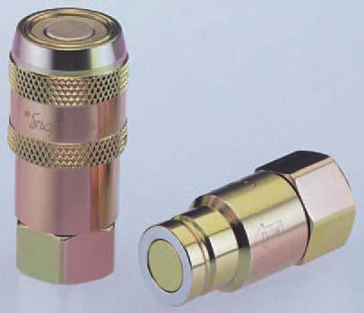
124


125


126
127


128

129


130
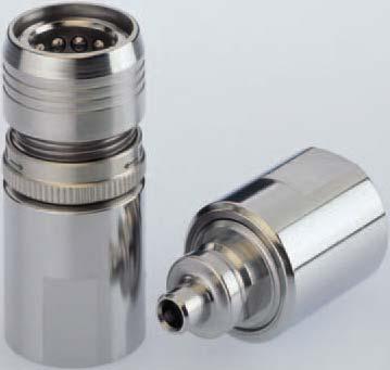

131
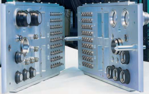
132
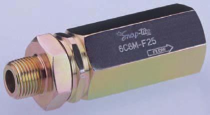


133

134

135
136 ISO-9001 Certified
 1/8 through nominal diameter 16 Stainless Steel or (1) Exotic Alloy Flat-face design simplifies contaminant")


137 71 Series - Drybreak, Flush Face Couplings Style ISO Interchange Max. Working Pressure Sizes Available Material Features Double Shut-off None,000 psi (690 bar) 1/8 through nominal diameter 16 Stainless Steel or (1) Exotic Alloy Flat-face design simplifies contaminant inspection and cleaning Flush Valve virtually eliminates fluid loss and air inclusion Wide Variety of specialty seal options available Sleeve-Lock option prevents accidental disconnection 5 Series -Poppet Style, Chemical Couplings Style ISO Interchange Max. Working Pressure Sizes Available Material Features Double Shut-off or Straight-Through combination None 1,000 psi (69 bar) 1/ through 1/ nominal diameter 16 Stainless Steel or (1) Exotic Alloy Designed for difficult or aggressive media Teflon Seals are standard Tubular barrel valve design enhances flow rate Sleeve-Lock option prevents accidental disconnection K Series - Poppet Style, Cyrogenic Couplings Style ISO Interchange Max. Working Pressure Sizes Available Material Features Double Shut-off or Straight-Through combination None 1,000 psi (69 bar) /8 through nominal diameter 16 Stainless Steel or (1) Exotic Alloy Cryogenic operation to -00 F/-0 C Designed for difficult or aggressive media Teflon or Kel F Seals are standard options Sleeve-Lock option prevents accidental disconnection 8-1 Series - Drybreak, Low Pressure-Low Profile Couplings Style ISO Interchange Max. Working Pressure Sizes Available Material Features Double Shut-off None 1,000 psi (69 bar) 1/ through nominal diameter 16 Stainless Steel, Aluminum Recessed coupling face eases hidden connections Lightweight, Low-profile design Flush Valve virtually eliminates fluid loss and air inclusion Wide variety of specialty seal options available Color coded positive connection indicator (1) - Specialty wetted metal parts such as Inconel, Hastelloy, and others can be made available. Please consult factory. - Specialty Seal options are available. See last page of brochure for chart. - All couplings shown can be indexed (key d) (max 6 based on size) to prevent mixing/contamination.

 1/ through 6 nominal diameter 16 Stainless Steel, Aluminum, or (1)")
 1/ through nominal diameter 16 Stainless Steel, Aluminum,")

138 Poppet Style, General Purpose Couplings - H Series Style ISO Interchange Max. Working Pressure Sizes Available Material Features Poppet Style, Vacuum and Steam Couplings - E-EA Series Style ISO Interchange Max. Working Pressure Sizes Available Material Features Poppet Style, ISO-B Interchange Couplings - 7 Series Style ISO Interchange Max. Working Pressure Sizes Available Material Features Double, Single Shut-off or Straight-Through combination None,000 psi (690 bar) 1/ through 6 nominal diameter 16 Stainless Steel, Aluminum, or (1) Exotic Alloy Optional Break-away design available Two-piece construction expands end fitting selection Smooth jet stream valve design lowers pressure drop Wide variety of specialty seal options available Sleeve-lock option prevents accidental disconnection Double, Single Shut-off or Straight-Through combination None,000 psi (7 bar) 1/ through nominal diameter 16 Stainless Steel, Aluminum, or (1) Exotic Alloy Designed for hard vacuums down to 9.7 Hg Excellent high temperature sealing Two-piece construction expands end fitting selection Wide variety of specialty seal options available Sleeve-lock option prevents accidental disconnection Double Shut-off or Straight-Through combination ISO 71-1 Series B (ISO B) 5,500 psi (80 bar) 1/8 through 1 nominal diameter or 16 Stainless Steel or (1) Exotic Alloy Meets or exceeds ISO 71-1 Series B standards Proven ball-lock mechanism for positive connection Wide variety of specialty seal options available Sleeve-lock option prevents accidental disconnection Poppet Style, Thread-to-Connect Couplings - 75 Series Style ISO Interchange Max. Working Pressure Sizes Available Material Features Double Shut-off or Straight-Through combination None 1,650 psi (11 bar) / through nominal diameter 16 Stainless Steel or (1) Exotic Alloy High flow chemical transfer coupling Acme thread-to-connect design for heavy duty service Connects under static pressure up to 1,650 psi/11 bar Low pressure drop keeps flow rates high (1) - Specialty wetted metal parts such as Inconel, Hastelloy, and others can be made available. Please consult factory. - Specialty Seal options are available. See last page of brochure for chart. - All couplings shown can be indexed (key d) (max 6 based on size) to prevent mixing/contamination.
 / through 1-1/ nominal diameter 16 Stainless Steel Interchange compatible thread-to-connect design Connects")
 1/ through nominal diameter 16 Stainless Steel or (1) Exotic Alloy Two-piece construction")
 Teflon (- to 00 F/-75 to 5 C) Kel-F (-00 to 00 F/-0 to 5 C) Kalrez (- to 500 F/- to 60 C) Chemraz (- to 500 F/- to 60 C) (1) - Specialty wetted metal parts such as Inconel,")
 (max 6 based on size) to prevent mixing/contamination. Seal Compound 71 Series Notes: - Wide variety of additional seal materials available.")
139 78 Series - Drybreak, Screw-to-Connect Couplings Style ISO Interchange Max. Working Pressure Sizes Available Material Features Double shut-off None,000 psi (7 bar) / through 1-1/ nominal diameter 16 Stainless Steel Interchange compatible thread-to-connect design Connects under static pressure up to,000 psi (7 bar) Bulkhead mountable nipple option available 6C & C Series - Inline Check Valves Style Safety Factor Max. Working Pressure Sizes Available Material Features Soft seat, zero leakage, poppet style :1 6,000 psi (1 bar) 1/ through nominal diameter 16 Stainless Steel or (1) Exotic Alloy Two-piece construction expands end fitting selection Various crack pressures available Flow rates to 175 gpm/66 lpm Seal Availability Buna N (-0 to 0 F/-0 to 9 C) Ethylene Propylene (EPDM) (-65 to 0 F/-55 to 150 C) Viton (-15 to 00 F/- to 5 C) Teflon (- to 00 F/-75 to 5 C) Kel-F (-00 to 00 F/-0 to 5 C) Kalrez (- to 500 F/- to 60 C) Chemraz (- to 500 F/- to 60 C) (1) - Specialty wetted metal parts such as Inconel, Hastelloy, and others can be made available. Please consult factory. - Specialty Seal options are available. See last page of brochure for chart. - All couplings shown can be indexed (key d) (max 6 based on size) to prevent mixing/contamination. Seal Compound 71 Series Notes: - Wide variety of additional seal materials available. Chart provided for reference only. - Coupling selection must assure compatibility of body and seal materials with the fluid media. Contact factory with any questions concerning specific product application needs. - Ethylene Propylene (EPDM) is not compatible with mineral based oils/solvents. 5 Series 6C/C Series! WARNING! FAILURE OR IMPROPER SELECTION OR IMPROPER USE OF THE PRODUCTS AND/OR SYSTEMS DESCRIBED HEREIN OR RELATED ITEMS CAN CAUSE DEATH, PERSONAL INJURY AND PROPERTY DAMAGE. This document and other information from Snap-tite, Inc., its subsidiaries and authorized distributors provide product and/or system options for further investigation by users having technical expertise. It is important that you analyze all aspects of your application and review the information concerning the product or system in the current product catalog. Due to the variety of operation conditions and applications for these products or systems, the user, through its own analysis and testing, is solely responsible for making the final selection of the products and systems and assuring that all performance, safety and warning requirements of the application are met. The products described herein, including without limitation, product features, specifications, designs, availability and pricing, are subject to change by Snap-tite, Inc. and its subsidiaries at any time without notice. K Series 8-1 Series H Series E-EA Series 7 Series 75 Series 78 Series Distributed By: BE-070 ISO-9001 Certified
23 SERIES INDUSTRIAL DRY BREAK COUPLINGS. Featuring Snap-tite quality with superior pressure and flow characteristics over the competition
 INDUSTRIAL DRY BREAK COUPLINGS SERIES Featuring Snap-tite quality with superior pressure and flow characteristics over the competition Rugged construction High strength steel with Zinc Trivalent Chromate
74 Series ISO Interchange
 Series ISO 8 Interchange Featuring Snap-tite quality with superior pressure and flow characteristics over the competition. Flush Face/Dry Break design facilitates easy cleaning prior to connection High
Snap-tite Quick Disconnect Couplings for Applications Requiring Virtually No Air Inclusion or Spillage
 Snap-tite Quick Disconnect Couplings for Applications Requiring Virtually No Air Inclusion or Spillage 8- Series For Pressures to 0 psi ( bar) 9 Series For Pressures to 0 psi ( bar) Featuring: Low pressure
ISO Interchange SERIES
 ISO 18 Interchange SERIES Series ISO 18 Interchange Featuring Snap-tite quality with superior pressure and flow characteristics over the competition. Flush Face/Dry Break design facilitates easy cleaning
28-1 & 29 Series. Compact, Light Weight Non-Spill Couplings. Compact Couplings for Applications Requiring Minimal Air Inclusion or Spillage
 8- & 9 Series Compact, Light Weight Non-Spill Couplings Compact Couplings for Applications Requiring Minimal Air Inclusion or Spillage Both 8- and 9 Series are non-spill, push-to-connect couplings designed
Snap-tite E / EA-Series
 Snap-tite E / EA-Series eneral Purpose and Vacuum Couplings eaturing... Snap-tite quality with superior pressure and flow characteristics over the competition. Snap-tite's EA Series quick disconnect coupling
Quick Disconnect Couplings & Hydraulic Valves
 Quick Disconnect Couplings & Hydraulic Valves Introduction Performance without Compromise on a Global Scale Since 1935, the Quick Disconnect and Valve Division of Snap-tite Inc., has offered more combinations,
Quick Disconnect Couplings & Hydraulic Valves
 Quick Disconnect Couplings & Hydraulic Valves Introduction Performance without Compromise on a Global Scale Since 1935, the Quick Disconnect and Valve Division of Snap-tite Inc., has offered more combinations,
HK Series - 2 Way 1HK to 8 HK 1 8" to 1" Body
 HK Series - 2 Way 1HK to 8 HK 1 8" to 1" Body Series HK Couplings are designed for general purpose hydraulic service. Some are suitable for use with various liquids, chemicals, steam, gases, and vacuum.
A World Class Tradition of Quality
 Snap-tite offers a full line of NGV1 fueling products. A World Class Tradition of Quality 2 Snap-tite Quality, Safety, Ingenuity F ounded over 65 years ago, Snap-tite has grown into a corporation producing
Group 14. Quick Release Couplings High pressure
 Group 14 Quick Release s High pressure 14 INDEX Page Contents 2 Index 3 Technical information Tema Quick Release s Hydraulic Series 4 Tema Series 2500 for Hydraulic 5 Tema Series 3800 for Hydraulics 6
Catalog Hydraulic Couplings High Pressure
 High Pressure 3 Series Threaded Actuation Design Threaded Sleeve The 3 Series coupling are designed for high pressure applications. The coupler sleeve and nipple body must be manually threaded together
Q U I C K C O U P L I N G S, C O U P L E R A D A P T E R S & R E P L A C E M E N T T I P S Engineered, Machined and Assembled in the USA Since 1969
 Q U I C K C O U P L I N G S, C O U P L E R A D A P T E R S & R E P L A C E M E N T T I P S Engineered, Machined and Assembled in the USA Since 1969 warning statement! WARNING Failure, improper use or improper
Ball Valves 2-Way Series
 Ball Valves 2-Way Series Pressures to 20,000 psi (1379 bar) Autoclave Engineers high-pressure ball valves have been designed to provide superior quality for maximum performance within a variety of valve
Ball Valves 2-Way Series
 Ball Valves 2-Way Series Pressures to 20,000 psi (1379 bar) Autoclave Engineers high-pressure ball valves have been designed to provide superior quality for maximum performance within a variety of valve
Quick Coupling Products
 Quick Coupling Products Quick Couplings, Swivels, Valves, Diagnostic Equipment Catalog 3800 USA February 2014 Locations Grantsburg, WI Chetek, WI Union City, PA FAILURE OR IMPROPER SELECTION OR IMPROPER
Hydraulic. Quick Couplings
 Hydraulic Quick Couplings B-1 Introduction Double Shut-Off and Straight-Thru Couplings Parker hydraulic couplings have a wide variety of designs, each tailored to a particular application or use. This
Compressed Natural Gas Vehicle Fueling Products AGA/CGA NGV1 CERTIFIED. ISO-9001 Certi fied
 Compressed Natural Gas Vehicle Fueling Products AGA/CGA NGV1 CERTIFIED ISO-9001 Certi fied Snap-tite offers a full line of NGV1 fueling products. A World Class Tradition of Quality 2 Snap-tite Quality,
The Future in Motion. Hydraulics 2014 Quick Couplings.
 The Future in Motion Hydraulics 2014 Quick Couplings www.contitech.us Quick Couplings 1 Quick Coupling Series Descriptions QS10 Series A general purpose, double shut-off, poppet valve style quick coupling,
SECTION 15 Breakaway Couplers
 SECTION Breakaway Couplers Make Model Page Intertraco Intertraco Intertraco Intertraco Intertraco Intertraco Series A & B Breakaway Couplers Series J, N & P Breakaway Couplers Series E & S Breakaway Couplers
Colorflow and Ball Valves. Industrial Flow Control, Check, Gauge Control. Catalog HY /US
 Colorflow and Industrial Flow Control, Check, Gauge Control Catalog HY14-3300/US Colorflow and Fully guided poppets are used on Colorflow valves rather than the less durable ball-check type construction.
Quick Coupling Products
 Quick Coupling Products Quick Couplings, Swivels, Valves, Diagnostic Equipment Catalog 3800 USA February 2014 Locations Grantsburg, WI Chetek, WI Union City, PA FAILURE OR IMPROPER SELECTION OR IMPROPER
High Pressure Gear Pumps & Motors Series PZG Pumps Series MZG Motors
 High Pressure Gear Pumps & Motors Series PZG Pumps Series MZG Motors Bulletin 650-Z1 High Pressure Gear Pumps and Gear Motors for today s demanding mobile and industrial applications. The PZG and MZG Series
Quick Coupling Products
 Quick Coupling Products Quick Couplings, Swivels, Valves, Diagnostic Equipment Catalog 3800 USA July 202 Locations Grantsburg, WI Chetek, WI FAILURE OR IMPROPER SELECTION OR IMPROPER USE OF THE PRODUCTS
Parker Autoclave Engineers: Fluid Components Product Catalog. February Valves, Fittings and Tubing. Pressures to 150,000 psi (10,000 bar)
") Parker Autoclave Engineers: Fluid Components Product Catalog February 2013 Valves, Fittings and Tubing Pressures to 150,000 psi (10,000 bar) Ball Valves Subsea Series Internal Pressures to 20,000 psi (1379
Parker Autoclave Engineers: Fluid Components Product Catalog February 2013 Valves, Fittings and Tubing Pressures to 150,000 psi (10,000 bar) Ball Valves Subsea Series Internal Pressures to 20,000 psi (1379
Mobile Cylinder Div. Standard Build Series. Catalog HY /US Rev C
 Mobile Cylinder Div. Standard Build Series Catalog HY18-0014/US Rev C WARNING - USER RESPONSIBILITY FAILURE OR IMPROPER SELECTION OR IMPROPER USE OF THE PRODUCTS DESCRIBED HEREIN OR RELATED ITEMS CAN CAUSE
Hydraulic Quick Couplings
 Double Shut-Off and Straight-Thru Couplings Parker hydraulic couplings have a wide variety of designs, each tailored to a particular application or use. This catalog is arranged according to those categories.
Rotary Plug Valves (PR Series) Catalog 4126-PR Revised, July 2003
 Catalog 4126-PR Revised, July 2003") Rotary Plug Valves (PR Series) Catalog 4126-PR Revised, July 2003 PR Series Rotary Plug Valves Introduction Parker PR Series Plug Valves provide positive leak tight shut-off, high flow capacity, and quick
Rotary Plug Valves (PR Series) Catalog 4126-PR Revised, July 2003 PR Series Rotary Plug Valves Introduction Parker PR Series Plug Valves provide positive leak tight shut-off, high flow capacity, and quick
Aeroquip Ultra-Mate Couplings
 Aeroquip Ultra-Mate Couplings The Ultimate in Push-Pull Couplings Self-Seal, Self-Locking Couplings Automatic Pull-Home Valve Sleeve Tactile Locking Pins Vacuum to 5000 psi Patent 6,557,824 2 EATON Aerospace
Catalog Pnuematic Couplings
 Industrial Interchange Nipples A-A-59439, MIL- C-4109F Design Non-valved, straight through Pioneer Industrial Interchange Nipples are compatible for use with 20 Series, HF Series, Universal or E-z-mate
Introduction Parker are designed for uni-directional flow control of fluids and gases in industries such as chemical processing, oil and gas productio
 Check Valves (C Series) Catalog 4130-C Revised, July 2004 Introduction Parker are designed for uni-directional flow control of fluids and gases in industries such as chemical processing, oil and gas production
Quick Couplings. Pioneer offers the widest range of quick couplings on the market, and has a product for nearly every agricultural application.
 Pioneer has been The Farmer s Choice for more than 60 years, and it is the world leader in quick coupling products for the agricultural industry. These products are manufactured in state-of-the-art manufacturing
Hydraulic Quick Couplers - Order Today, SHIP TODAY at Quick Coupling Products
 Quick Coupling Products Quick Couplings, Swivels, Valves, Diagnostic Equipment Catalog 3800 USA February 2014 Locations Grantsburg, WI Chetek, WI Union City, PA FAILURE OR IMPROPER SELECTION OR IMPROPER
Flat Face. Flat Face. Series: A Premier Interchange: ISO ISO Interchange Couplings
 ISO 16028 Interchange Couplings Flat Face Overview A or Premier series offers higher pressure ratings, superior flow ratings, lower pressure drop compared to FIRG series or competitors products. Flat Face
Flow Control Valves Check Valves Gauge Control Valves. Colorflow Valves
 Check Valves Gauge Control Valves Colorflow Valves Colorflow and Ball Valves Industrial Flow Control, Check, Gauge Control Catalog HY14-3300/US Colorflow and Ball Valves Fully guided poppets are used on
Couplings - Quick Disconnect
 ouplings - Quick isconnect Hydraulic - eneral Purpose... -1-3, -6 Hydraulic - Non Spill...-4-6 Pneumatic - eneral Purpose Manual onnect...-7-9 Pneumatic - eneral Purpose Push-to-onnect...-1-13 Industrial
Aeroquip Sure-Mate Couplings
 Aeroquip Sure-Mate Couplings Positive locking fingers Blunt start ACME threads for easy connection Lighter weight compared to previous thread-together couplings Low pressure drop across the connector Minimal
Quick Coupling Products
 Quick Coupling Products Quick Couplings, Swivels, Valves, Diagnostic Equipment Catalog 3800 USA February 2014 Locations Grantsburg, WI Chetek, WI Union City, PA FAILURE OR IMPROPER SELECTION OR IMPROPER
Moduflow. ILP and RFP Low Pressure Filters. Series
 Moduflow ILP and RFP Low Pressure Filters Series 27 Applications for Moduflow Filters Power Unit Fabrication Off-line Filter Loops Mobile Equipment The Moduflow filter is widely considered the most versatile
Hydraulic Quick Couplings
 Double Shut-Off and Straight-Thru Couplings Parker hydraulic couplings have a wide variety of designs, each tailored to a particular application or use. This catalog is arranged according to those categories.
Valves. E Valves. Multiple Hydraulic System Applications
 s Multiple Hydraulic System Applications Parker Check s are unidirectional flow control devices used primarily in hydraulic systems to eliminate potential damage caused by fluid back pressure. Offered
Aeroquip Sure-Mate Couplings
 Aeroquip Sure-Mate Couplings Positive locking fingers Blunt start ACME threads for easy connection Lighter weight compared to previous thread-together couplings Low pressure drop across the connector Minimal
MagnePump. Recirculation MagnePumps. At a Glance:
 MagnePump Recirculation MagnePumps Parker Autoclave Engineers MagnePumps eliminate or reduce many of the problems associated with conventional pumps, such as leakage, contamination and packing heat generation.
Pneumatic Quick Couplings
 Pneumatic Quick ouplings -1 maku GmbH & o. KG 73630 Remshalden Telefon (0 71 51) 7 26 26 Telefax (0 71 51) 7 42 01 www.maku-industrie.de Pneumatics Pneumatic Quick ouplings Single Shut-Off ouplings Single
QUICK COUPLINGS C101 PLATED STEEL COUPLER C102 PLATED STEEL NIPPLE
 C100 couplings are compliant with the ISO-7241-B standard. They also interchange with the following Manufacturer's: Snaptite 72, Hansen HK, Parker 60, Faster HNV, & Areoquip FD45. Larger sleeves on this
A PREMIER SERIES FLAT FACE COUPLERS ISO Interchange
 A PREMIER SERIES FLAT FACE COUPLERS ISO 16028 Interchange The A Premier Series Flat Face ISO 16028 Interchange Couplings offer higher pressure ratings, superior flow characteristics, and lower pressure
Check Valves (C Series) Catalog 4130-C Revised, July 2004
 Catalog 4130-C Revised, July 2004") Check Valves (C Series) Catalog 4130-C Revised, July 2004 Introduction Parker C Series Check Valves are designed for uni-directional flow control of fluids and gases in industries such as chemical processing,
Check Valves (C Series) Catalog 4130-C Revised, July 2004 Introduction Parker C Series Check Valves are designed for uni-directional flow control of fluids and gases in industries such as chemical processing,
QUICK COUPLINGS C101 PLATED STEEL COUPLER C102 PLATED STEEL NIPPLE C101L PLATED STEEL COUPLER WITH LOCKING SLEEVE C102B BRASS NIPPLE
 C100 couplings are compliant with the ISO-7421-B standard. They also interchange with the following Manufacturer's: Snaptite 72, Hansen HK, Parker 60, Faster HNV, & Areoquip FD45. Larger sleeves on this
C101 PLATED STEEL COUPLER C102 PLATED STEEL NIPPLE
 C100 couplings are compliant with the ISO-7421-B standard. They also interchange with the following Manufacturer's: Snaptite 72, Hansen HK, Parker 60, Faster HNV, & Areoquip FD45. Larger sleeves on this
Parker Autoclave Engineers: Fluid Components Product Catalog. February Valves, Fittings and Tubing. Pressures to 150,000 psi (10,000 bar)
") Parker Autoclave Engineers: Fluid omponents Product atalog February 2013 Valves, Fittings and Tubing Pressures to 150,000 psi (10,000 bar) Fittings and Tubing Low Pressure Pressures to 15,000 psi (1034
Parker Autoclave Engineers: Fluid omponents Product atalog February 2013 Valves, Fittings and Tubing Pressures to 150,000 psi (10,000 bar) Fittings and Tubing Low Pressure Pressures to 15,000 psi (1034
Quick Coupling Products
 Quick Coupling Products Quick Couplings, Swivels, Valves, Diagnostic Equipment Catalog 38 USA February 14 Locations Grantsburg, WI Chetek, WI Union City, PA FAILURE OR IMPROPER SELECTION OR IMPROPER USE
HYDRAULIC HEAVY DUTY
 Catalog #HHD-16 12/16 HYDRAULIC HEAVY DUTY Series HHD 3000 PSI RATED 10-25-16 WARNING IMPROPER SELECTION, IMPROPER USE OR FAILURE OF THE PRODUCTS AND/OR SYSTEMS DESCRIBED HEREIN CAN CAUSE PROPERTY DAMAGE,
Ball Valves 3-Way Series
 Ball Valves 3-Way Series Pressures to 20,000 psi (1379 bar) Distributed By: Parker Autoclave Engineers high-pressure ball valves have been designed to provide superior quality for maximum performance within
Thermoplastic Couplings
 Thermoplastic ouplings Thermoplastics -1 Quick oupling Division Thermoplastic ouplings Table of ontents Thermoplastics oupling Selection Guide...-3 Spectrum Series...-4 Specifications...-4 ouplers...-5
SensoControl Diagnostic Equipment
 SensoControl Diagnostic Equipment Together, We Can Measure and Record Critical Data A Wise Investment An ounce of prevention Diagnosing a problem before it occurs should be your primary objective. Whether
Hydraulic and Pneumatic In-line and Cartridge Insert Control Valves for any fluid or gas.
 2010 TECHNICAL CATALOG FROM CONCEPT TO PERFORMANCE... KEPNER VALVES DELIVER ZERO LEAKAGE CONTROL! Hydraulic and Pneumatic In-line and Cartridge Insert Control Valves for any fluid or gas. Kepner Products
Inline Adapters are Electro Polished to 10 Ra Max. 2 Valves supplied with Metal to Metal Face Seal connections have
 CRYOGENIC RELIEF VALVE (STAINLESS) 1/4" and 1/2" NPT -4 and -8 Metal To Metal Face Seal 1/4" and 1/2" Bi-Lok Dual Ferrule Tube 10-750 Psig (0.69-51.7 Bar) STAINLESSCRV Description The Generant Series Stainless
Wire Reinforced Synthetic Rubber Hose Assemblies
 Aeroquip Wire Reinforced Synthetic Rubber Hose Assemblies Lightweight and Flexible Qualified to Industry Standards Integral Abrasion and Fire Resistance Covers Available Aeroquip Wire Reinforced Synthetic
Accessories. Section Outline
 Fisher Controls offers a line of accessories including filters, needle valves, pressure gauges, vent assemblies, and emergency shutoff valves. This section provides technical information for these accessories.
Aeroquip 145/155 Series Hydraulic Self Sealing Coupling
 Aeroquip 145/155 Series Hydraulic Self Sealing Coupling Fully interchangeable with all fielded Eaton's Aeroquip 145/155 Series Couplings and is the only approved coupling to SAE AS5440 Table of Contents
500 Series Adjustable Popoff & Inline Relief Valves.5 to 150 PSIG
 Fred C. Gilbert Co. 106 Norris Road Bakersfield, Ca. 93308 661-399-9569 fax 661-393-9654 Adjustable Popoff & Inline Relief Valves.5 to 150 PSIG Features Popoff or Inline Valves Adjustable Crack Pressure
CVH103P. Check Valve Series CVH103P. Technical Information. General Description
 Catalog HY-351/US Information Cartridge Style Valve. For additional information see Tips on pages 1-4. Valve Series H13P Spherical poppet for low leakage D -Ring eliminates back-up rings Dual sense paths
CAT GB. Quick-release couplings for Diagnosis. UNI EN ISO 9001 Cert. n 2905 ISO/TS 16949
 CAT. 0117-GB Quick-release couplings for Diagnosis UNI EN ISO 9001 Cert. n 2905 ISO/TS 16949 Quick-release couplings for Diagnosis Features Applications Benefits Recoendations Interchangeable according
T5 Series Pressures to 5,000 psi (345 bar)
") Quality Pascal Industries manufactures each component with the utmost care and attention. Materials are carefully selected to Pascal Industries proprietary standards to ensure the highest quality. Components
Quality Pascal Industries manufactures each component with the utmost care and attention. Materials are carefully selected to Pascal Industries proprietary standards to ensure the highest quality. Components
Aerospace. Aeroquip Brand Ultra-Mate Couplings. Patent 6,557,824
 Aerospace Aeroquip Brand Ultra-Mate Couplings The Ultimate in Push-Pull Couplings Self-Seal, Self-Locking Couplings Automatic Pull-Home Valve Sleeve Tactile Locking Pins Vacuum to 5000 psi Patent 6,557,824
Anti-Vibration Collet Gland Assembly
 nti-vibration Gland ssembly Pressures to 20,000 psi (1379 bar) Sizes to 1-1/2 (38.10 mm) For extreme conditions of vibration and/or shock in tubing systems, such as an uned line near a compressor, conedand-threaded
Needle Valves (VQ Series) Catalog 4110-VQ Revised, July 2001
 Catalog 4110-VQ Revised, July 2001") Needle Valves (VQ Series) Catalog 4110-VQ Revised, July 2001 Introduction Parker VQ Series Needle Valves are the right combination of performance and value for manual or pneumatic onoff control in moderate
Needle Valves (VQ Series) Catalog 4110-VQ Revised, July 2001 Introduction Parker VQ Series Needle Valves are the right combination of performance and value for manual or pneumatic onoff control in moderate
Sinclair Collins. Process Control Valves. For Steam, Hot and Cold Liquids -40 to 450 F up to 500 psi. Catalog SCV-100/USA April 2001
 Sinclair Collins Process Control Valves For Steam, Hot and Cold Liquids -40 to 450 F up to 500 psi April 2001 The Diaphragm Operated Valves on the following pages are designed for directing, diverting
Pressure Instrument Testing Equipment
 Pressure Instrument Testing Equipment BULLETIN TE-1 A Halliburton Company A Durable, Portable Primary Standard Model 1305D Deadweight Tester The Ashcroft 1305D Deadweight Tester is an affordable, portable
Aerospace Parts Catalogue 2
 Werthenbach Aerospace GmbH Page 1 Table of Content 1. Quick Disconnect s... 3 1.1. APPLICATION GUIDE... 4 1.1.1. AEROQUIP SERIES 145/155 SERIES HYDRAULIC SELF SEALING COUPLINGS... 4 1.1.2. AEROQUIP SERIES
Rubber Hose, Fittings & Assemblies for Aerospace Applications
 Aeroquip Rubber Hose, Fittings & Assemblies for Aerospace Applications Lightweight and Flexible Qualified to Industry Standards Table of Contents 306 Low Pressure Hose, Fittings and Assemblies 1 303, 302A
Lubrication Fittings. 1/4"-28 Taper Thread Fittings
 1/4"-28 Taper Thread Fittings Used on most cars and trucks and many industrial machines. It is recommended that SAE-LT taper threads be assembled into 1/4"-28 UNF, Class 3B, straight threaded holes having
Introduction Parker are designed for uni-directional flow control of fluids and gases in industries such as chemical processing, oil and gas productio
 Check Valves (CO Series) Catalog 4130-CO Revised, June 2001 Introduction Parker are designed for uni-directional flow control of fluids and gases in industries such as chemical processing, oil and gas
PT Series Tank Top Filters
 Tank Top Filters 9 Applications Together we can Preserve the environment. Minimize waste and promote energy efficiency. Achieve worldwide filtration solutions. Build global confidence. Redefine new limits.
Control Valves & Valve Accessories
 Control Valves & Valve Accessories PNEUMADYNE, INC. Catalog 400 Phone 76-559-077 Fax 76-559-0547 Stainless Steel 0- Fully Ported valve with M5 threads available- contact factory Viton is a registered trademark
Bladder Accumulators za03 Bottom Repairable Top Repairable Medium Flow High Flow Transfer Barrier Gas Bottle
 LADDER PRODUCTS za03 ottom Repairable Top Repairable Medium Flow High Flow Transfer arrier Gas ottle Features: Operating Pressures to 6600 PSI Ten Different Capacities from 10 cu in to 15 gallons Nine
Check valves Direct and pilot operated check valve functions for applications up to 350 bar (5000 psi) and 227 L/min (60 USgpm)
 and 227 L/min (60 USgpm)") Hydraulic Screw-in Cartridge Valves (SiCV) Check valves Direct and pilot operated check valve functions for applications up to 5 bar (5 psi) and 7 L/min (6 USgpm) Check valves CHECK VALVES... -4 FPR -
Hydraulic Screw-in Cartridge Valves (SiCV) Check valves Direct and pilot operated check valve functions for applications up to 5 bar (5 psi) and 7 L/min (6 USgpm) Check valves CHECK VALVES... -4 FPR -
Pneumatic Products st»
 » Pneumatic Products » Industry Standouts for Over 50 Years The benefits of an innovative, pneumatic coupling design were solid enough to single-handedly launch CEJN in 1955. This reliable, easy-to-handle
Ball Valves (B Series) Catalog 4121-B September 1999
 Catalog 4121-B September 1999") Ball Valves (B Series) Catalog 4121-B September 1999 Two-Way B Series Ball Valves Introduction Parker manually, pneumatically, and electrically actuated two-way B Series Ball Valves provide quick 1/4 turn
Ball Valves (B Series) Catalog 4121-B September 1999 Two-Way B Series Ball Valves Introduction Parker manually, pneumatically, and electrically actuated two-way B Series Ball Valves provide quick 1/4 turn
Ford Fabricated Steel Products
 Ford Fabricated Steel Products Section N2 12/2000 The Ford Meter Box Co., Inc. 775 Manchester Avenue, P.O. Box 443, Wabash, Indiana, USA 46992-0443 Telephone: 219/563-3171 FAX: 1-800-826-3487 Overseas
SC HYDRAULIC ENGINEERING CORPORATION
 Designers and Manufacturers of Hydraulic and Pneumatic Equipment SC HYDRAULIC ENGINEERING CORPORATION 1130 Columbia Street - Brea, California 92821 - USA Phone (714) 257-4800 - Fax (714) 257-4810 10 SERIES
SERIES: VLS. INTERCHANGE: With similar couplings MAIN APPLICATIONS. Mobile construction equipment Drilling rigs Vehicle/Trailer Industrial plant
 INTERCHANGE: With similar couplings MAIN APPLICATIONS Mobile construction equipment Drilling rigs Vehicle/Trailer Industrial plant VLS series is the screw to connect coupling with poppet style valving,
QUICK COUPLINGS DHI. ver. 0001
 QUICK COUPLINGS DHI www.manuli-hydraulics.com Q.SAFE DHI INTRODUCTION MQS-DHI DIRECT HOSE INTEGRATION An innovative system to enable direct assembly of the quick-release coupling to the flexible hose,
Check Valves (CO Series) Catalog 4130-CO Revised, June 2001
 Catalog 4130-CO Revised, June 2001") Check Valves (CO Series) Catalog 4130-CO Revised, June 2001 Introduction Parker are designed for uni-directional flow control of fluids and gases in industries such as chemical processing, oil and gas
Check Valves (CO Series) Catalog 4130-CO Revised, June 2001 Introduction Parker are designed for uni-directional flow control of fluids and gases in industries such as chemical processing, oil and gas
Quick couplers. Chapter H. Quick couplers
 Table of contents Chapter Rogan series 30,000 psi maximum working pressure P006 Coupler... -3 P006 Nipple (without check valve)... -4 P006 Nipple (with check valve)... -5 P010 Coupler... -6 P010 Nipple
Aviation Ground Fueling Solutions
 Aviation Ground Fueling Solutions for Commercial and Military Applications Fueling/Refueling Nozzles & Accessories Military Underwing Refueling Nozzles For pressurized underwing or fuselage refueling of
Ball Valves (B Series) Catalog 4121-B Revised, November 2001
 Catalog 4121-B Revised, November 2001") Ball Valves (B Series) Catalog 4121-B Revised, November 2001 Two-Way B Series Ball Valves Introduction Parker manually, pneumatically, and electrically actuated two-way B Series Ball Valves provide quick
Ball Valves (B Series) Catalog 4121-B Revised, November 2001 Two-Way B Series Ball Valves Introduction Parker manually, pneumatically, and electrically actuated two-way B Series Ball Valves provide quick
PF Series Thermoplastic Non-Spill Couplings and Industrial Hose Products
 PF Series Thermoplastic Non-Spill Couplings and for Bulk Chemical and Fluid Transfer Bulletin 3800-PF August, 2004 PF Series Non-Spill Quick Couplings Parker PF Series non-spill couplings virtually eliminate
Quick Couplings. Section F
 Quick ouplings Section conomatic Quick onnect...2-3 Sleevmatic...4-6...7-8 conomatic Quick onnect ouplings...9-10 Pneumatic ivision 1 Richland, Michigan Pneumatic Products irline ccessories Numbers & imensions
Pounds Per Square Inch (PSI)
") Nozzle Size Selection Chart Determine the nozzle size by the pressure washer s GPM @ PSI (gallons per minute @ a specific pounds per square inch). If the nozzle size is too small, your equipment can be
Nozzle Size Selection Chart Determine the nozzle size by the pressure washer s GPM @ PSI (gallons per minute @ a specific pounds per square inch). If the nozzle size is too small, your equipment can be
Schrader industrial products catalog. couplers & Plugs
 Schrader industrial products catalog couplers & Plugs Coupler Coupler & Plug Conected Plug Couplers & Plugs Quick Disconnect couplers are the fastest, easiest, and the most reliable means of joining pneumatic
1004D2/1005E API Bottom Loading Coupler. 1005E Small handles used throughout Europe 1004D
 PART #H32183PA February 2009 1004D2/1005E API Bottom Loading Coupler The 1004D2 is the standard in drip-less bottom loading couplers and a proven performer at major oil terminals worldwide. The 1004D2
HIGH PRESSURE FILTERS Series HF2P
 HIGH PRESSURE FILTERS Series HF2P Pressures to 3000 psi Flows to 25 GPM Port Size 3/4 APPLICATION HYDAC HF2 Inline High- Pressure Filters are designed for use on hydraulic power units, machine tools, plastics,
Blow out Prevention Couplings
 CUSTOMER SERVICE INNOVATION MANUFACTURING QUALITY TECHNICAL EXPERTISE EXCELLENCE DESIGN Blow out Prevention Couplings Customer Service: +44 (0)1772 323529 www.dixoneurope.co.uk Dixon Blowout Prevention
FLAT FACE COUPLINGS FIRG SERIES FLAT FACE, QUICK RELEASE HYDRAULIC COUPLINGS PREMIER RANGE INTRODUCTION ADVANTAGES APPLICATIONS OPERATION
 FLAT FACE COUPLINGS FIRG SERIES PREMIER RANGE INTRODUCTION Holmbury FIRG Series couplings were first introduced in 1982. Their early success was due to good performance, long life and competitive prices.
W91/W94 Series TEMPERATURE REGULATORS. Self-Operated Temperature Regulators. Design & Operation W91 Non-Indicating W94 Dial Thermometer
 Design & Operation W91 Non-Indicating W94 Dial Thermometer Watson McDaniel reserves the right to change the designs and/or materials of its products without notice. 2010 Watson McDaniel Company CAPILLARY
Series 105 Simplex Strainer Cast Iron Swing Bolt O-Ring Closure, Flanged Connection Class 125 ANSI Flat Face Flange Rating VENT 'A' FLOW
 Series 105 Simplex Strainer Cast Iron Swing Bolt O-Ring Closure, Flanged Connection Class 125 ANSI Flat Face Flange Rating 1/4" NPT VENT 'A' 1/4" NPT 2 - REQ'D 'D' REQ D FOR BASKET REMOVAL 'B' FLOW 'C'
Quick Coupling Products Distribution. Catalogue 3800-DS/UK
 Quick Coupling Products Distribution Catalogue 38-DS/UK For your safety! Under certain circumstances, quick couplings can be subjected to extreme loadings such as vibration and uncontrolled pressure peaks.
AS/ASH SERIES ALUMINUM PNEUMATIC AND HYDRAULIC CYLINDERS... 6
 AS/ASH SERIES ALUMINUM PNEUMATIC AND HYDRAULIC CYLINDERS............. 6 Section 6 8 ORDERING INFORMATION For Rod End Dimensions see back cover foldout... Basic Cylinder No Mount.0" to 4.00" For pressure
Complete Hydraulic Set System 100
 Diagnostics System 100 Measuring-System System 100 Technical The design of the Tema System 100 allows the check of static and dynamic pressures as well as vacuum. With the integrated self-venting device