Hydraulic and Pneumatic In-line and Cartridge Insert Control Valves for any fluid or gas.
|
|
|
- Milo Richard
- 6 years ago
- Views:
Transcription
1 2010 TECHNICAL CATALOG FROM CONCEPT TO PERFORMANCE... KEPNER VALVES DELIVER ZERO LEAKAGE CONTROL! Hydraulic and Pneumatic In-line and Cartridge Insert Control Valves for any fluid or gas. Kepner Products Company: 995 North Ellsworth Avenue, Villa Park, Illinois FAX


2 More than 60 years in business and continuous improvement are your assurance of the best in product performance. RELIABILITY SINCE 1948 We've been designing and producing control valves that out-deliver and outlast the competition. Our secret? Simple; we focus on basic concepts to provide the best check valves in the industry. You face a myriad of design challenges in your product. Specify the check valve you can rely on. QUALITY...EVERY TIME Kepner valves are engineered and manufactured to the highest possible standards, ensuring they work when you need them to and for years to come. AVAILABILITY We don't just have the best products. We utilize manufacturing and scheduling techniques to provide them when you need them. Our customer support... staffed by personnel with many years of experience...is there to provide assistance and answer questions quickly Kepner Products Company
3 Products and General Information Inline Valves Check and Relief Check Valves Adjustable Relief Valves High Pressure Check/Relief Check Valves Ball Check Valves Shuttle Valves Fixed Orifice Flow Restrictor Valves Split Flange Check Valves Cartridge Type Insert Versions Cartridge Check and Relief Check Valves Cartridge Adjustable Relief Valves Cartridge Shuttle Valves Cartridge Lock Valves Pneumatic Cartridge Lock Valves Lock Valves Single Lock Valves Pneumatic Single Lock Valves Dual Lock Valves O-Ring Specification Guide Application and Product Suitability Material Selection and Safety Flow Coefficients Approximate Valve Weights Standard Terms and Conditions of Sale Web Site Information Technical Catalog Supplement - Tips and Applications


4 Our unique Flexible Seal Seat assures bubble-tight performance. The Kepner Flexible Seal Seat design offers positive leakage control of liquid or gas. The seat design is a carefully engineered combination of metal-to-metal and resilient O-Ring seal contact. The O-Ring is securely retained at the seat rather than on the poppet, protecting it from the destructive abrading and blasting effect of the flow; seal life is extended. Seat wire drawing common to conventional valves has been eliminated by the Flexible Seal Seat design. The seal closes around scratches, dents, and other irregularities and effectively prevents any leakage past the seat. A wide choice of O- Ring seal elastomers is offered for system compatibility. The Flexible Seal Seat design is available in check, relief, shuttle, and pilot operated check valves, and has been successfully applied to millions of fluid control situations. CLOSED OPEN CLOSED No Flow Full Flow Reverse Flow Checked CLOSED: (No Flow) Relaxed O-Ring seal and gentle seal-to-poppet contact guarantees low pressure sealing and eliminates valve chatter. OPEN: Seal flexes to close off all external leakage around end cap. (Full Flow) Enclosure protects O-Ring seal, prevents seal displacement. CLOSED: (Reverse Checked) Seal still holding external leakage now also flexes around poppet. Higher pressures tighten the seal. Bubble-tight shutoff. u LEAK TIGHT SEALING u POSITIVE ACTION EVEN AT LOW PRESSURE u FREEDOM FROM CHATTER

5 Inline Check and Relief Check Valves These spring-operated poppet valves, with optional relief settings, allow free flow in only one direction and prevent backflow - sometimes referred to as backflow preventor, flow stop, or non-return valve. They are also used for relief and bypass functions. Kepner s Flexible Seal Seat combines metal-to-metal contact with a resilient seal seat ensuring dependable bubble-tight shutoff of liquid or gas, and long service life. Standard and specialty valve designs handle a wide variety of applications. Features and Benefits: Flexible Seal Seat TM for zero leakage (bubble-tight) sealing at low and high pressures. O-Ring seal positively secured. Non-pressurized threads. Poppet stop inside valve body prevents spring from bottoming out. Generous flow passages allow full flow with minimal pressure drop. Valve Specifications: Port Configurations: Pipe or Tube (NPT, JIC; 12 Combinations) Port Sizes: 1/8 inch to 3 inch (3.2 mm to 76 mm) Body Materials: Aluminum, Brass, Steel, 303 or 316 Stainless Steel O-Ring Seals: Buna-N, Neoprene, Teflon, Viton, EP, others available Temperature: -300 F to 450 F (-184 C to 232 C), O-Ring dependent Check Crack Pressure: 1-2 PSI (.07 bar to.14 bar) Relief/Check Crack Pressures: 5 PSI (.35 bar), 10 PSI (0.7 bar), 25 PSI (1.7 bar), 50 PSI (3.5 bar) and 65 PSI (4.5 bar), others available Operating Pressure: to 3,000 PSI (207 bar) Flow: to 500 GPM (1893 LPM)
6 Inline Check and Relief Check Valves Part Numbers: Fixed Settings 1/8 to 3 sizes PORT CONFIGURATIONS 19 IJIC - IJIC 7 JIC - MPT IJIC IJIC JIC MPT TUBE TO TUBE TUBE TO PIPE 17 JIC - IJIC 5 MPT - JIC JIC IJIC MPT JIC TUBE TO TUBE PIPE TO TUBE 15 IJIC - JIC 4 FPT - FPT IJIC JIC FPT FPT TUBE TO TUBE PIPE TO PIPE 13 JIC - JIC 3 MPT - MPT JIC JIC MPT MPT TUBE TO TUBE PIPE TO PIPE 11 JIC - FPT 2 FPT - MPT JIC FPT FPT MPT TUBE TO PIPE PIPE TO PIPE 9 FPT - JIC 1 MPT - FPT FPT JIC MPT FTP PIPE TO TUBE PIPE TO PIPE Consult Factory or Distributor for more help. Customer/user is solely responsible to select products suitable for their specific application requirements and to ensure proper installation, operation and maintenance of these products. Improper selection or use of products can cause personal injury or property damage. All sales are subject to Kepner Products Company Standard Terms and Conditions of Sale. Design subject to change without notice. PART NUMBER EXAMPLE 4 06 C CRACK PRESSURE PORT SIZES 04 = 1/8 PIPE - 1/4 TUBE 16 = 1 PIPE - 1 TUBE 06 = 1/4 PIPE - 3/8 TUBE 20 = 1 1/4 PIPE - 1 1/4 TUBE 08 = 3/8 PIPE - 1/2 TUBE 24 = 1 1/2 PIPE - 1 1/2 TUBE 10 = 1/2 PIPE - 5/8 TUBE 32 = 2 PIPE - 2 TUBE 12 = 3/4 PIPE - 3/4 TUBE 48 = 3 PIPE (CONSULT FACTORY) Blank = 1-2 PSI CRACK (Standard) 5 = 5 PSI CRACK 10 = 10 PSI CRACK 25 = 25 PSI CRACK 50 = 50 PSI CRACK 65 = 65 PSI CRACK OTHERS AVAILABLE CONSTRUCTION MATERIALS A = ALUMINUM D = 303 STAINLESS STEEL B = BRASS i F = 316 STAINLESS STEEL C = STEEL O-RING SEALS 1 = BUNA-N 3* = TEFLON 9 = NEOPRENE 18 = VITON 25 = ETHYLENE PROPYLENE OTHERS AVAILABLE


7 Inline Check and Relief Check Valves Flow Charts: Sizes 1/8-1 Curves indicate Pressure Drop vs Flow Rate PRESSURE DROP - PSI FLOW - GALLONS PER MINUTE Test Fluid: Water Test Temp: 50 o F PRESSURE DROP - PSI SIZE CONNECTIONS 04 1/8 Pipe or 1/4 Tube 06 1/4 Pipe or 3/8 Tube 08 3/8 Pipe or 1/2 Tube 10 1/2 Pipe or 5/8 Tube 12 3/4 Pipe or 3/4 Tube 16 1 Pipe or 1 Tube EXAMPLE WITH VARIOUS RELIEF SETTINGS FLOW - GALLONS PER MINUTE Test Fluid: MIL-H-5606A HYDRAULIC OIL Test Temp: 70 o F Consult Factory or Distributor for more help. Customer/user is solely responsible to select products suitable for their specific application requirements and to ensure proper installation, operation and maintenance of these products. Improper selection or use of products can cause personal injury or property damage. All sales are subject to Kepner Products Company Standard Terms and Conditions of Sale. Design subject to change without notice.

8 Flow Charts: Sizes 1 1 / 4-2 Inline Check and Relief Check Valves SIZES: 1-1/4 1-1/2 2 Curves indicate Pressure Drop vs Flow Rate PRESSURE DROP - PSI FLOW - GALLONS PER MINUTE Test Fluid: Water Test Temp: 50 o F SIZE CONNECTIONS /4 Pipe or Tube /2 Pipe or Tube PRESSURE DROP - PSI FLOW - GALLONS PER MINUTE Test Fluid: MIL-H-5606A HYDRAULIC OIL Test Temp: 70 o F 32 2 Pipe or Tube EXAMPLE WITH VARIOUS RELIEF SETTINGS Consult Factory or Distributor for more help. Customer/user is solely responsible to select products suitable for their specific application requirements and to ensure proper installation, operation and maintenance of these products. Improper selection or use of products can cause personal injury or property damage. All sales are subject to Kepner Products Company Standard Terms and Conditions of Sale. Design subject to change without notice.


9 Inline Check and Relief Check Valves Dimensions: Model 100 A B C (REF) D E F HEX CONNECTION: G CONNECTION: H Model 200 NOTES BELOW REFER TO COLUMN F 1 1 1/2 FOR 316 STAINLESS STEEL 2 1 7/8 FOR 303 & 316 STAINLESS STEEL 3 2 3/4 FOR COMMERCIAL BRASS A C (REF) D E B F HEX CONNECTION: G CONNECTION: H NOTES BELOW REFER TO COLUMN F 1 1 1/2 FOR 316 STAINLESS STEEL 2 1 7/8 FOR 303 & 316 STAINLESS STEEL Model /4 FOR COMMERCIAL BRASS A B C (REF) B D E F HEX CONNECTION: G CONNECTION: H ALL DIMENSIONS (IN INCHES) ARE FOR REFERENCE ONLY. NOTES BELOW REFER TO COLUMN F 1 1 1/2 FOR 316 STAINLESS STEEL 2 1 7/8 FOR 303 & 316 STAINLESS STEEL 3 2 3/4 FOR COMMERCIAL BRASS

 B2 D E F HEX CONNECTION: G CONNECTION: H ALL DIMENSIONS (IN INCHES) ARE FOR REFERENCE ONLY.")
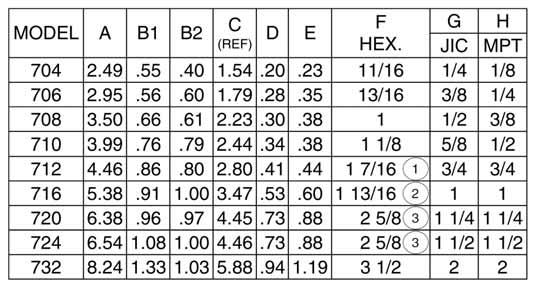
10 Inline Check and Relief Check Valves Dimensions: Model 400 A D E F HEX CONNECTION: G CONNECTION: H NOTES BELOW REFER TO COLUMN F 1 1 1/2 FOR 316 STAINLESS STEEL 2 1 7/8 FOR 303 & 316 STAINLESS STEEL 3 2 3/4 FOR COMMERCIAL BRASS Model 500 B1 A C (REF) B2 D E F HEX CONNECTION: G CONNECTION: H Model 700 NOTES BELOW REFER TO COLUMN F 1 1 1/2 FOR 316 STAINLESS STEEL 2 1 7/8 FOR 303 & 316 STAINLESS STEEL 3 2 3/4 FOR COMMERCIAL BRASS B1 A C (REF) B2 D E F HEX CONNECTION: G CONNECTION: H ALL DIMENSIONS (IN INCHES) ARE FOR REFERENCE ONLY. NOTES BELOW REFER TO COLUMN F 1 1 1/2 FOR 316 STAINLESS STEEL 2 1 7/8 FOR 303 & 316 STAINLESS STEEL 3 2 3/4 FOR COMMERCIAL BRASS
 A NOTES BELOW REFER TO COLUMN F 1 1 1/2 FOR 316 STAINLESS STEEL 2 1 7/8 FOR 303 & 316")


11 Inline Check and Relief Check Valves Dimensions: Model 900 C (REF) A D E F HEX CONNECTION: G CONNECTION: H Model 1100 B C (REF) A NOTES BELOW REFER TO COLUMN F 1 1 1/2 FOR 316 STAINLESS STEEL 2 1 7/8 FOR 303 & 316 STAINLESS STEEL 3 2 3/4 FOR COMMERCIAL BRASS D E F HEX CONNECTION: G CONNECTION: H Model 1300 A NOTES BELOW REFER TO COLUMN F 1 1 1/2 FOR 316 STAINLESS STEEL 2 1 7/8 FOR 303 & 316 STAINLESS STEEL 3 2 3/4 FOR COMMERCIAL BRASS B C (REF) B D E F HEX CONNECTION: G CONNECTION: H ALL DIMENSIONS (IN INCHES) ARE FOR REFERENCE ONLY. NOTES BELOW REFER TO COLUMN F 1 1 1/2 FOR 316 STAINLESS STEEL 2 1 7/8 FOR 303 & 316 STAINLESS STEEL 3 2 3/4 FOR COMMERCIAL BRASS


12 Dimensions: Model 1500 Inline Check and Relief Check Valves C (REF) A D E B F HEX CONNECTION: G CONNECTION: H Model 1700 NOTES BELOW REFER TO COLUMN F 1 1 1/2 FOR 316 STAINLESS STEEL 2 1 7/8 FOR 303 & 316 STAINLESS STEEL 3 2 3/4 FOR COMMERCIAL BRASS A B C (REF) D E F HEX CONNECTION: G CONNECTION: H Model 1900 NOTES BELOW REFER TO COLUMN F 1 1 1/2 FOR 316 STAINLESS STEEL 2 1 7/8 FOR 303 & 316 STAINLESS STEEL 3 2 3/4 FOR COMMERCIAL BRASS A D E F HEX CONNECTION: G CONNECTION: H ALL DIMENSIONS (IN INCHES) ARE FOR REFERENCE ONLY. NOTES BELOW REFER TO COLUMN F 1 1 1/2 FOR 316 STAINLESS STEEL 2 1 7/8 FOR 303 & 316 STAINLESS STEEL 3 2 3/4 FOR COMMERCIAL BRASS

13 Adjustable Inline Relief Valves These adjustable, spring-loaded poppet valves are used to limit system pressure. Excess pressure unseats the poppet, allowing flow with minimal increase in system pressure. As fluid is released the system pressure decreases until the spring force re-seats the poppet. Kepner's Flexible Seal Seat ensures bubble-tight shutoff of liquid or gas. The relief pressure can be set using a tamperproof internal adjustment screw. Standard and specialty valves handle a wide variety of applications requiring fast acting relief performance and tamperproof pressure adjustment. Features and Benefits: Flexible Seal Seat for zero leak (bubble-tight) seal Outer O-Ring provides non-pressurized threads Both O-Ring seals positively secured Wide relief adjustment range 50 to 2000 PSI (3.45 to 138 bar) Tamperproof Nylok adjustment to set relief pressure/prevent slippage Poppet stop inside valve body prevents spring from bottoming out Valve Specifications: End Connections: Pipe (MPT, FPT; 10 combinations) Inlet (MPT or FPT); Outlet (FPT); Side Outlet (1/4 inch FPT) Port Sizes: 1/4 inch, 3/8 inch, 1/2 inch Body Materials: Steel, 303 Stainless Steel O-Ring Seals: Teflon, other materials available Temperature: -300 F to 450 F (-184 C to 232 C), O-Ring dependent Crack Pressure Ranges: Adjustable 50 to 2000 PSI (3.5 to 138 bar) 3 Spring Ranges: 50 to 400 PSI (3.5 to 28 bar), 300 to 1000 PSI (21 to 69 bar), 900 to 2000 PSI (62 to 138 bar); factory preset pressure available Operating Pressure: to 3000 PSI (207 bar) Flow: to 10 GPM (38 LPM)


14 RELIEF LIMITING PRESSURE - PSI Adjustable Inline Relief Valves Flow Charts: Initial Setting MODEL * Curves indicate Pressure Drop vs Flow Rate RELIEF LIMITING PRESSURE - PSI FLOW RATE - GPM Initial Setting MODEL * RELIEF LIMITING PRESSURE - PSI Initial Setting MODEL * FLOW RATE - GPM Consult Factory or Distributor for more help. Customer/user is solely responsible to select products suitable for their specific application requirements and to ensure proper installation, operation and maintenance of these products. Improper selection or use of products can cause personal injury or property damage. All sales are subject to Kepner Products Company Standard Terms and Conditions of Sale. Design subject to change without notice. FLOW RATE - GPM Test Fluid: MIL-H-5606A Hydraulic Oil Test Temp: 100 o F (Viscosity 77.5 SUS) *TYP. - Covers Models 2300 thru 2309

15 Adjustable Inline Relief Valves Dimension Diagram and Part Numbers: Model: B D A C (REF) 1.19 H SIDE PORT 1 1/8 HEX All dimensions (in inches) for reference only. Model: CONNECTION: E.47 CONNECTION: G A D 1.19 H SIDE PORT CONNECTION: F.47 CONNECTION: G 1 1/8 HEX PORT SIZES INLET OUTLET SIDE OUTLET 00 1/2 MPT 1/2 FPT NONE 01 1/2 FPT 1/2 FPT NONE 02 3/8 MPT 3/8 FPT NONE 03 3/8 FPT 3/8 FPT NONE 04 1/4 MPT 1/4 FPT 1/4 FPT 05 1/4 FPT 1/4 FPT 1/4 FPT 06 1/2 MPT 1/4 FPT 1/4 FPT 07 1/2 FPT 1/4 FPT 1/4 FPT 08 3/8 MPT 1/4 FPT 1/4 FPT 09 3/8 FPT 1/4 FPT 1/4 FPT C = STEEL CONSTRUCTION MATERIALS D = 303 STAINLESS STEEL i CRACK PRESSURE RANGES 400 = PSI CRACK = PSI CRACK 2000 = PSI CRACK PART NUMBER EXAMPLE C (750PSI) BASE NO. FACTORY PRESET CRACK PRESSURE OPTIONAL O-RING SEALS: TEFLON
16

17 High Pressure Check and Relief/Check Valves These inline valves allow free flow in only one direction, prevent backflow, and meet the industry's need for higher operating pressures. They also are used for relief and by-pass functions. Kepner's Flexible Seal Seat combines metal-to-metal contact with a resilient seal seat ensuring bubble-tight shutoff of liquid or gas. This is an ideal choice for applications that require positive leak-tight sealing and long service life at pressures to 6000 PSI. Standard and specialty valves handle a wide variety of applications. Features and Benefits: Flexible Seal Seat for zero leak (bubble-tight) sealing to 6000 PSI O-Ring seal positively secured Non-pressurized threads Poppet stop inside valve body prevents spring from bottoming out Generous flow passages allow full flow with minimal pressure drop Valve Specifications: End Connections: Pipe or Tube (NPT, JIC; 12 combinations) Port Sizes: 1/8 inch to 1 inch (3.2 mm to 25 mm) Body Materials: Steel, 303 Stainless Steel O-Ring Seals: Teflon, other materials available Temperature: -300 F to 450 F (-184 C to 232 C), O-Ring dependent Relief/Check Valve Crack Pressures: 5 PSI (.35 bar), 10 PSI (0.7 bar), 25 PSI (1.7 bar), 50 PSI (3.5 bar) and 65 PSI (4.5 bar), others available Operating Pressure: to 6000 PSI (414 bar) Flow: to 25 GPM (95 LPM)

18 High Pressure Check and Relief/Check Valves Flow Chart and Part Number: Fixed settings 1/8 to 1 sizes. PRESSURE DROP - PSI Consult Factory or Distributor for more help. Customer/user is solely responsible to select products suitable for their specific application requirements and to ensure proper installation, operation and maintenance of these products. Improper selection or use of products can cause personal injury or property damage. All sales are subject to Kepner Products Company Standard Terms and Conditions of Sale. Design subject to change without notice. FLOW - GALLONS PER MINUTE Test Fluid: Water Test Temp: 50 o F PORT CONFIGURATIONS 59 IJIC - IJIC 47 JIC - MPT IJIC IJIC JIC MPT TUBE TO TUBE TUBE TO PIPE PART NUMBER EXAMPLE C JIC - IJIC 45 MPT - JIC JIC IJIC MPT JIC TUBE TO TUBE PIPE TO TUBE 55 IJIC - JIC 44 FPT - FPT IJIC JIC FPT FPT TUBE TO TUBE PIPE TO PIPE 53 JIC - JIC 43 MPT- MPT JIC JIC MPT MPT TUBE TO TUBE PIPE TO PIPE 51 JIC - FPT 42 FPT - MPT JIC FPT FPT MPT TUBE TO PIPE PIPE TO PIPE 49 FPT - JIC 41 MPT - FPT FPT JIC MPT FTP PIPE TO TUBE PIPE TO PIPE CRACK PRESSURE 5 = 5 PSI CRACK 10 = 10 PSI CRACK 25 = 25 PSI CRACK 50 = 50 PSI CRACK 65 = 65 PSI CRACK OTHERS AVAILABLE PORT SIZES 04 = 1/8 PIPE - 1/4 TUBE 10 = 1/2 PIPE - 5/8 TUBE 06 = 1/4 PIPE - 3/8 TUBE 12 = 3/4 PIPE - 3/4 TUBE 08 = 3/8 PIPE - 1/2 TUBE 16 = 1 PIPE - 1 TUBE CONSTRUCTION MATERIALS O-RING SEALS 3 = TEFLON C = STEEL D = 303 STAINLESS STEEL
 D E F HEX CONNECTION: G CONNECTION: H")
 D E B F HEX CONNECTION: G CONNECTION: H Model 4300 B NOTES REFER TO")


19 High Pressure Check and Relief/Check Valves Dimensions: Fixed settings 1/8 to 1 sizes Model 4100 A B C (REF) D E F HEX CONNECTION: G CONNECTION: H NOTES REFER TO COLUMN F 1 1 7/8 FOR 303 STAINLESS STEEL Model 4200 A C (REF) D E B F HEX CONNECTION: G CONNECTION: H Model 4300 B NOTES REFER TO COLUMN F 1 1 7/8 FOR 303 STAINLESS STEEL A C (REF) B D E F HEX CONNECTION: G CONNECTION: H Model 4400 NOTES REFER TO COLUMN F 1 1 7/8 FOR 303 STAINLESS STEEL A D E F HEX ALL DIMENSIONS (IN INCHES) ARE FOR REFERENCE ONLY. CONNECTION: G CONNECTION: H NOTES REFER TO COLUMN F 1 1 7/8 FOR 303 STAINLESS STEEL
 B2 D E F HEX CONNECTION: G CONNECTION: H")
 E B2 F HEX CONNECTION: G CONNECTION: H Model 4900 NOTES REFER TO")

 ARE FOR REFERENCE ONLY.")
20 High Pressure Check and Relief/Check Valves Dimensions: Fixed settings 1/8 to 1 sizes Model 4500 B1 A C (REF) B2 D E F HEX CONNECTION: G CONNECTION: H Model 4700 B1 NOTES REFER TO COLUMN F 1 1 7/8 FOR 303 STAINLESS STEEL D A C (REF) E B2 F HEX CONNECTION: G CONNECTION: H Model 4900 NOTES REFER TO COLUMN F 1 1 7/8 FOR 303 STAINLESS STEEL A C (REF) D E B F HEX CONNECTION: G CONNECTION: H Model 5100 NOTES REFER TO COLUMN F 1 1 7/8 FOR 303 STAINLESS STEEL B D A C (REF) E F HEX CONNECTION: G CONNECTION: H ALL DIMENSIONS (IN INCHES) ARE FOR REFERENCE ONLY. NOTES REFER TO COLUMN F 1 1 7/8 FOR 303 STAINLESS STEEL
 B D E F HEX CONNECTION: G CONNECTION: H")
 D E B F HEX CONNECTION: G CONNECTION: H NOTES REFER TO COLUMN F 1 1")


21 High Pressure Check and Relief/Check Valves Dimensions: Fixed settings 1/4 to 1 sizes Model 5300 B A C (REF) B D E F HEX CONNECTION: G CONNECTION: H NOTES REFER TO COLUMN F 1 1 7/8 FOR 303 STAINLESS STEEL Model 5500 A C (REF) D E B F HEX CONNECTION: G CONNECTION: H NOTES REFER TO COLUMN F 1 1 7/8 FOR 303 STAINLESS STEEL Model 5700 B D A C (REF) E F HEX CONNECTION: G CONNECTION: H Model 5900 D NOTES REFER TO COLUMN F 1 1 7/8 FOR 303 STAINLESS STEEL A E F HEX ALL DIMENSIONS (IN INCHES) ARE FOR REFERENCE ONLY. CONNECTION: G CONNECTION: H NOTES REFER TO COLUMN F 1 1 7/8 FOR 303 STAINLESS STEEL
22
. They are trouble free with large flow paths.")
23 Inline Ball Check Valves Ball check valves allow free flow in only one direction, prevent backflow, and are for applications where poppet style valves may not be suitable (such as media with contamination, viscous fluids, etc.). They are trouble free with large flow paths. The need for closely mating surfaces and sliding parts has been eliminated by the conical tension spring and seal seat design. Kepner's Flexible Seal Seat design combines metal-to-metal contact with a resilient seal seat to ensure bubble-tight shutoff of liquid or gas, and long service life. Features and Benefits: Flexible Seal Seat for zero leak (bubble-tight) seal at low and high pressures O-Ring seal positively secured Stainless steel ball design; no sliding parts Exclusive conical tension spring design allows for greater flow Handles contamination, viscous liquids and slurries Valve Specifications: End Connections/Sizes: 1/8 inch to 3/4 inch FPT Body Materials: Brass, 303 Stainless Steel O-Ring Seals: Buna-N, Teflon, Viton, other materials available Temperature: -300 F to 450 F (-184 C to 232 C), O-Ring dependent Crack Pressure: 1 to 3 PSI (.07 bar to 0.21 bar) Operating Pressure: to 3000 PSI (207 bar) Flow: to 25 GPM (95 LPM)


24 Inline Ball Check Valves Dimension Diagram, Part Numbers and Flow Chart: A D B HEX CONNECTION: C CONNECTION: C ALL DIMENSIONS (IN INCHES) ARE FOR REFERENCE ONLY. BASE MODEL NUMBER PART NUMBER EXAMPLE 4 56 B - 1 PORT SIZES 54 = 1/8 FPT 60 = 1/2 FPT 56 = 1/4 FPT 62 = 3/4 FPT 58 = 3/8 FPT CONSTRUCTION MATERIALS B = BRASS D = 303 STAINLESS STEEL i O-RING SEALS 1 = BUNA-N 3 = TEFLON 18 = VITON CRACK PRESSURE: 1-3 PSI CRACK PRESSURE DROP - PSI Curves indicate Pressure Drop vs. Flow Rate FLOW - GALLONS PER MINUTE Test Fluid: MIL-H-5606A Hydraulic Oil Test Temp: 75 o F MODEL SIZE FEMALE PIPE THREAD 454 1/ / / / /4

25 Inline Shuttle Valves The shuttle valve permits flow from either of two inlet ports to a common outlet. A free floating metal ball shuttles according to the relative pressure at the two inlets. The higher pressure inlet flows through the valve and moves the ball to close the opposite inlet. Kepner's Flexible Seal Seat combines metal-to-metal contact with a resilient seal seat to ensure bubble-tight shutoff of liquid or gas, and long service life. Shuttle valves can also flow in the reverse direction, and relieve system pressure when input is removed. Standard and specialty valves handle a wide variety of control applications, including use in logic circuits, for pilot signal input and venting, dual input pilot control, and for switching to alternate or standby systems. Features and Benefits: Flexible Seal Seat for zero leak (bubble-tight) seal at closed port Non-biased free floating shuttle ball with short travel path Minimal pressure differential shifting O-Ring seal positively secured Unobstructed flow paths allow full flow and minimal pressure drop Valve Specifications: End Connections/Sizes: 1/8 inch to 3/4 inch FPT Body Materials: Brass, Steel, 303 Stainless Steel O-Ring Seals: Buna-N, Teflon, Viton, other materials available Temperature: -300 F to 450 F (-184 C to 232 C), O-Ring dependent Operating Pressure: to 3000 PSI (207 bar) Flow: to 60 GPM (227 LPM)
 E 2E D OUTLET CONNECTION H NPTF I BASE MODEL NUMBER PORT SIZES 54 = 1/8 FPT 60 = 1/2 FPT 56 = 1/4 FPT 62 = 3/4 FPT 58 = 3/8 FPT CONSTRUCTION MATERIALS B = BRASS C = STEEL D = 303")

26 Shuttle Valves Dimension Diagram, Part Numbers and Flow Chart: INLET CONNECTION H NPTF A INLET CONNECTION H NPTF C G HEX B ALL DIMENSIONS (IN INCHES) ARE FOR REFERENCE ONLY. F DIA. THRU (2 PLACES) E 2E D OUTLET CONNECTION H NPTF I BASE MODEL NUMBER PORT SIZES 54 = 1/8 FPT 60 = 1/2 FPT 56 = 1/4 FPT 62 = 3/4 FPT 58 = 3/8 FPT CONSTRUCTION MATERIALS B = BRASS C = STEEL D = 303 STAINLESS STEEL i PART NUMBER EXAMPLE C - 1 O-RING SEALS 1 = BUNA-N 3 = TEFLON 9 = NEOPRENE 18 = VITON 25 = ETHYLENE PROPYLENE CRACK PRESSURE: 1-3 PSI CRACK PRESSURE DROP - PSI Curves indicate Pressure Drop vs. Flow Rate MODEL SIZE NPTF FEMALE PIPE THREAD / / / / /4 FLOW - GALLONS PER MINUTE Test Fluid: MIL-H-5606A Hydraulic Oil Test Temp: 75 o F

27 Fixed Orifice Flow Control Restrictor Valves Fixed Orifice Flow Controls provide free flow in one direction and restricted (metered) flow in the reverse direction. They are standard Kep-O-seal or Kepsel check valves, equipped with a calibrated orifice drilled through the valve poppet nose. Kepner's bubble-tight Flexible Seal Seat ensures that the reverse flow is precisely controlled by confining it to the calibrated orifice. Such valves are often used in charging lines for cylinders, containers, or accumulators where it is desired to rapidly charge and then bleed back the charged fluid at a pre-determined rate. These valves handle many other applications. Features and Benefits: Generous flow passages allow full free-flow with minimal pressure drop Metered reverse flow Tamperproof internal orifice Rugged and dependable Valve Specifications: Fixed Orifice Flow Control Restrictor sizes and specifications are the same as those shown for the standard Kep-O-seal or Kepsel check valves, except for cracking pressure and internal leakage which obviously do not apply. The valve orifice is drilled to customer's specifications. Test data and flow calibration based on Air or MIL-H-5606 Hydraulic Oil can be provided.
28 Fixed Orifice Flow Control Restrictor Valves Part Numbers: Kep-O-seal Inline and Kepsel Cartridge Type Insert Fixed Orifice Flow Control Restrictor Valves* 1/8 TO 3 SIZES PART NUMBER EXAMPLE 4 06 C (.062) See Kep-O-seal Inline Check and Relief Check Valves and add the Orifice Size to the Part Number as shown in the Part Number Example. ORIFICE SIZE (Thousandths of an inch) 1/16 to 2 NOMINAL SIZES PART NUMBER EXAMPLE C (.062) See Kepsel Cartridge Check and Relief Check Valves, and add the Orifice Size to the Part Number as shown in the Part Number Example. ORIFICE SIZE (Thousandths of an inch) *NOTE: All poppet designs can be converted to Flow Control Restrictor Valves by adding an Orifice and Designator as shown in the Part Number Examples above.

29 Split Flange Check and Relief/Check Valves The flanged, spring-operated, poppet valves allow free flow in only one direction and prevent backflow. They are also used for relief and by-pass functions. The valves can be direct mounted to pumps, motors, and other such applications where threaded end connections are impractical or inconvenient. Kepner's Flexible Seal Seat combines metal-to-metal contact with a resilient seal seat ensuring dependable bubble-tight shutoff of liquid or gas, as well as surge protection and long service life. Standard and specialty valve designs handle a wide variety of applications. Features and Benefits: Flexible Seal Seat for zero leak (bubble-tight) seal at low and high pressures SAE 4-bolt, Code 61 mounting; easy installation and maintenance O-Ring seal positively secured Poppet stop inside valve body prevents spring from bottoming out Generous flow passages allow full flow with minimal pressure drop Valve Specifications: Nominal SAE Flange Sizes: 3/4 inch to 2 inch (19 mm to 51mm) Body Materials: Steel O-Ring Seals: Buna-N, Neoprene, Viton, EP, other materials available Temperature: -300 F to 450 F (-184 C to 232 C), O-Ring dependent Check Valve Crack Pressure: 1 to 2 PSI (.07 bar to 0.14 bar) Relief/Check Valve Crack Pressures: 5 PSI (.35 bar), 10 PSI (0.7 bar), 25 PSI (1.7 bar), 50 PSI (3.5 bar), 65 PSI (4.5 bar), others available Operating Pressure: to 3000 PSI (207 bar) Flow: to 120 GPM (454 LPM)
 ARE FOR REFERENCE ONLY.")

30 Split Flange Check Valves Dimension Diagram and Part Numbers: G (4 PLACES) A INLET PORT O-RING GROOVE BOTH ENDS F B ALL DIMENSIONS (IN INCHES) ARE FOR REFERENCE ONLY. E C D A OUTLET PORT BASE MODEL NUMBER PART NUMBER EXAMPLE C (25) NOMINAL SIZES 12 = 3/4 24 = 1 1/2 16 = 1 32 = 2 20 = 1 1/4 CONSTRUCTION MATERIALS C = STEELi RELIEF CRACK PRESSURES 5=5 PSI CRACK 10=10 PSI CRACK 25=25 PSI CRACK 50=50 PSI CRACK 65=65 PSI CRACK O-RING SEALS 1 = BUNA-N 9 = NEOPRENE 18 = VITON 25 = ETHYLENE PROPYLENE OTHERS AVAILABLE STANDARD CRACK PRESSURE 1-3 PSI CRACK

31 Split Flange Check Valves Flow Charts: PRESSURE DROP - PSI Curves indicate Pressure Drop vs Flow Rate FLOW - GALLONS PER MINUTE Test Fluid: MIL-H-5606A HYDRAULIC OIL Test Temp: 50 o F MODEL SIZE SAE FLANGE /4 PRESSURE DROP - PSI / / EXAMPLE WITH VARIOUS RELIEF SETTINGS FLOW - GALLONS PER MINUTE Test Fluid: MIL-H-5606A HYDRAULIC OIL Test Temp: 70 o F Consult Factory or Distributor for more help. Customer/user is solely responsible to select products suitable for their specific application requirements and to ensure proper installation, operation and maintenance of these products. Improper selection or use of products can cause personal injury or property damage. All sales are subject to Kepner Products Company Standard Terms and Conditions of Sale. Design subject to change without notice.
32

33 Cartridge Type Insert Check Valves Kepsel cartridge valves are designed for simple installation (no expensive machining for cavity) and offer the same outstanding performance as their counterpart Kep-O-seal inline valves. These spring-operated poppet valves, with optional relief settings, allow free flow in only one direction and prevent backflow. They also are used for relief and by-pass functions. Kepner's Flexible Seal Seat ensures bubble-tight shutoff of liquid or gas, and long service life. Standard and specialty valve designs handle a wide variety of applications, and are ideal for use in subplate and manifold assemblies, pump inlet/outlet, and cylinder blocks. Features and Benefits: Flexible Seal Seat for zero leak (bubble-tight) seal at low and high pressures No threaded connections (avoid potential leakage) O-Ring seal positively secured Poppet stop inside valve body prevents spring from bottoming out Generous flow passages allow full flow with minimal pressure drop Compact, easy installation - Accessory Kepner Holding Device Kits available Valve Specifications: Nominal Sizes: 1/16 inch to 2 inch (1.6 mm to 51 mm; 9 Sizes) Body Materials: Brass, Steel, 303 or 316 Stainless Steel O-Ring Seals: Buna-N, Neoprene, Viton, EP, other materials available Temperature: -300 F to 450 F (-184 C to 232 C), O-Ring dependent Check Crack Pressure: 1 to 2 PSI (.07 bar to.14 bar) Relief/Check Crack Pressures: 5 PSI (.35 bar), 10 PSI (0.7 bar), 25 PSI (1.7 bar), 50 PSI (3.5 bar) and 65 PSI (4.5 bar), others available Operating Pressure: to 3000 PSI (207 bar) Flow: to 200 GPM (757 LPM)
 ALL DIMENSIONS (IN INCHES ARE FOR REFERENCE ONLY. 2) VALVE MUST BE HELD END - FOR - END IN USE. E H OUTLET DIA.")
34 Dimension Diagrams: Cartridge Type Insert Check Valves G D MODEL 2201 AND 2203 C J REF. A H INLET DIA. MODELS 2206 TO 2232 C REF. J D G F H OUTLET DIA. B A NOTES: H INLET DIA. 1) ALL DIMENSIONS (IN INCHES ARE FOR REFERENCE ONLY. 2) VALVE MUST BE HELD END - FOR - END IN USE. E H OUTLET DIA. DIRECTION OF FREE FLOW


35 PRESSURE DROP - PSI PRESSURE DROP - PSI PRESSURE DROP - PSI Cartridge Type Insert Check Valves Part Number and Flow Charts: BASE MODEL NUMBER PART NUMBER EXAMPLE C - 1 NOMINAL SIZES 01 = 1/16 08 = 3/8 16 = 1 03 = 1/8 10 = 1/2 24 = 1 1/2 06 = 1/4 12 = 3/4 32 = 2 CONSTRUCTION MATERIALS B = BRASS D = 303 STAINLESS STEEL C = STEEL i F = 316 STAINLESS STEEL O-RING SEALS 1 = BUNA-N 9 = NEOPRENE 18 = VITON 25 = ETHYLENE PROPYLENE OTHERS AVAILABLE FLOW GALLONS PER MINUTE Test Fluid: MIL-H-5606A Hydraulic Oil Test Temp: 75 F FLOW GALLONS PER MINUTE Test Fluid: MIL-H-5606A Hydraulic Oil Test Temp: 75 F FLOW GALLONS PER MINUTE Test Fluid: MIL-H-5606A Hydraulic Oil Test Temp: 75 F Consult Factory or Distributor for more help. Customer/user is solely responsible to select products suitable for their specific application requirements and to ensure proper installation, operation and maintenance of these products. Improper selection or use of products can cause personal injury or property damage. All sales are subject to Kepner Products Company Standard Terms and Conditions of Sale. Design subject to change without notice.
36

37 Cartridge Type Insert Adjustable Relief Valves The Kepsel cartridge has the same internal features as its counterpart Kep-O-seal adjustable inline relief valve.these adjustable, spring-loaded poppet valves are used to limit system pressure. Excess pressure unseats the poppet, allowing flow with minimal increase in system pressure. As fluid is released the system pressure decreases until the spring force re-seats the poppet. Kepner's Flexible Seal Seat ensures bubble-tight shutoff of liquid or gas. The relief pressure can be set using a tamperproof internal adjustment screw. Standard and specialty valves handle a wide variety of relief applications, and are ideal for use in a manifold, sub-plate, or cylinder head. Features and Benefits: Flexible Seal Seat for zero leak (bubble-tight) seal No threaded connections (avoid potential leakage) O-Ring seals positively secured Wide relief adjustment range 50 to 2000 PSI (3.45 to 138 bar) Tamperproof Nylok adjustment set relief pressure/prevent slippage Poppet stop inside valve body prevents spring from bottoming out Compact, easy installation - Accessory Kepner Holding Device Kits available Valve Specifications: Size: 1 inch cavity (25.4 mm) Body Materials: Steel, 303 Stainless Steel O-Ring Seals: Teflon, other materials available Temperature: -300 F to 450 F (-184 C to 232 C), O-Ring dependent Crack Pressure Ranges: Adjustable 50 to 2000 PSI (3.5 to 138 bar) 3 Spring Ranges: 50 to 400 PSI (3.5 to 28 bar), 300 to 1000 PSI (21 to 69 bar), 900 to 2000 PSI (62 to 138 bar); factory preset pressure available Operating Pressure: to 3000 PSI (207 bar) Flow: to 10 GPM (38 LPM)
38 Cartridge Type Insert Adjustable Relief Valves Dimension Diagram and Part Number: 2.151/ REF..999 / /.881 INLET PORT: 19/64 DIA..11 OUTLET PORT: 3/8 HOLLOW HEX. NOTES: 1. CRACK PRESSURE ADJUSTABLE 2. VALVE MUST BE HELD END FOR END IN USE 3. ALL DIMENSIONS (IN INCHES) ARE FOR REFERENCE ONLY PART NUMBER EXAMPLE 1354 C BASE MODEL NUMBER CONSTRUCTION MATERIALS C = STEEL D = 303 STAINLESS STEEL i O-RING SEALS EXTERNAL SEAL: STANDARD SIZE NUMBER: 020 INTERNAL SEAL: TEFLON Elastomeric seals available on request. ADJUSTMENT ADJUSTMENT RANGE By means of a standard 3/8 hex wrench inserted through the inline outlet port. MODEL SUFFIX ADJUSTMENT RANGE TO 400 PSI TO 1000 PSI TO 2000 PSI

39 Cartridge Type Insert Shuttle Valves The cartridge shuttle valve permits flow from either of two inlet ports to a common outlet. Similar to the Kep-O-seal inline version, a free floating metal ball shuttles according to the relative pressure at the two inlets. The higher pressure inlet flows through the valve and moves the ball to close the opposite inlet. Kepner's Flexible Seal Seat ensures bubble-tight shutoff of liquid or gas, and long service life. Shuttle valves can also flow in the reverse direction, and relieve system pressure when input is removed. Standard and specialty valves handle a wide variety of applications, and are ideal for use in manifolds, subplates, or cylinder heads. Features and Benefits: Flexible Seal Seat for zero leak (bubble-tight) seal at closed port No threaded connections (avoid potential leakage) Non-biased free floating shuttle ball with short travel path Minimal pressure differential shifting O-Ring positively secured Compact, easy installation - Accessory Kepner Holding Device Kits available Valve Specifications: Sizes: 1/16 inch to 3/4 inch Nominal sizes (1.6 mm to 19 mm) Body Materials: Brass, Steel, 303 Stainless Steel O-Ring Seals: Buna-N, Neoprene, Teflon, Viton, EP, others available Temperature: -300 F to 450 F (-184 C to 232 C), O-Ring dependent Operating Pressure: to 3000 PSI (207 bar) Flow: to 60 GPM (227 LPM)
 ARE FOR REFERENCE ONLY F Consult Factory or Distributor for more help.")
40 Cartridge Type Insert Shuttle Valves Dimension Diagram and Part Number: D G INLET E H (2 HOLES) G INLET A 45 TYP. C B REF. C ALL DIMENSIONS (IN INCHES) ARE FOR REFERENCE ONLY F Consult Factory or Distributor for more help. Customer/user is solely responsible to select products suitable for their specific application requirements and to ensure proper installation, operation and maintenance of these products. Improper selection or use of products can cause personal injury or property damage. All sales are subject to Kepner Products Company Standard Terms and Conditions of Sale. Design subject to change without notice. BASE MODEL NUMBER PART NUMBER EXAMPLE C - 1 NOMINAL SIZES 51 = 1/16 60 = 1/2 53 = 1/8. 62 = 3/4 56 = 1/4 CONSTRUCTION MATERIALS B = BRASS C = STEEL D = 303 STAINLESS STEEL i O-RING SEALS 1 = BUNA-N 6 = BUNA-N (90) 8 = VITON 9 = NEOPRENE 25 = ETHYLENE PROPYLENE
 and \"lock\" reverse flow until pilot pressure is applied to unlock the internal check valve and allow reverse flow.")
41 Cartridge Type Insert Lock Valves The cartridge lock valves combine a Kepsel Cartridge Insert Check with a rugged pilot operator, and function the same as the counterpart Kep-O-Lok inline lock valve. They free flow from valve port to cylinder port (or portion of circuit) and "lock" reverse flow until pilot pressure is applied to unlock the internal check valve and allow reverse flow. Kepner's Flexible Seal Seat provides positive bubble-tight locking to prevent load drift or circuit creep, and answers the need where internal leakage could adversely affect performance such as with clamping cylinders or outrigger stabilizer jacks. Standard and specialty valve designs handle a wide variety of block and load hold applications, and are ideal for use in manifolds, subplates, or cylinder heads. Features and Benefits: Flexible Seal Seat for zero leak (bubble-tight) seal locking No threaded connections (avoid potential leakage) Basic pilot ratio 3:1 Surge flow protected with calibrated pilot orifice Compact, easy installation - Accessory Kepner Holding Device Kits available Valve Specifications: Sizes: 1/16 inch to 3/4 inch Nominal sizes (1.6 mm to 19 mm) Body: Steel; Pilot Piston: Stainless; Poppet, Retainer, Rod: Steel O-Ring Seals: Teflon (internal check valve), Buna-N (external body chamfer) Temperature: -40 F to 300 F (-40 C to 149 C), O-Ring dependent Operating Pressure: to 3000 PSI (207 bar) Flow: to 40 GPM (151 LPM)
 ARE FOR REFERENCE ONLY 2.")


42 PRESSURE DROP - PSI PRESSURE DROP - PSI Cartridge Type Insert Lock Valves Dimension Diagram, Part Number and Flow Charts: D C 45 F B REF. 45 A J PILOT PORT G INLET PORT H HOLES NOTES: 1. ALL DIMENSIONS (IN INCHES) ARE FOR REFERENCE ONLY 2. VALVE MUST BE HELD END FOR END IN USE E K OUTLET PORT PART NUMBER EXAMPLE BASE MODEL NUMBER NOMINAL SIZES 41 = 1/16 43 = 1/8 46 = 1/4 50 = 1/2 52 = 3/4 CONSTRUCTION MATERIALS C = STEEL O-RING SEALS TEFLON CRACK PRESSURE 10 PSI CRACK Free Flow Piloted Open FLOW - GALLONS PER MINUTE FLOW - GALLONS PER MINUTE Test Fluid: MIL-H-5606A Hydraulic Oil Test Temp: 75 F 2752 Free Flow Piloted Open Consult Factory or Distributor for more help. Customer/user is solely responsible to select products suitable for their specific application requirements and to ensure proper installation, operation and maintenance of these products. Improper selection or use of products can cause personal injury or property damage. All sales are subject to Kepner Products Company Standard Terms and Conditions of Sale. Design subject to change without notice.
43 Pneumatic Cartridge Type Insert Lock Valves The pneumatic cartridge lock valves combine a Kepsel Cartridge Insert Check with a sealed pilot operator, and function the same as the counterpart Kep-O-Lok inline lock valve. They free flow from valve port to cylinder port (or portion of circuit) and "lock" reverse flow until pilot pressure is applied to unlock the internal check valve and allow reverse flow. Kepner's Flexible Seal Seat provides positive bubble-tight locking to prevent load drift or circuit creep, and answers the need where internal leakage could adversely affect performance such as with clamping cylinders or outrigger stabilizer jacks. Standard and specialty valve designs handle a wide variety of block and load hold applications, and are ideal for use in manifolds, subplates, or cylinder heads. Features and Benefits: Flexible Seal Seat for zero leak (bubble-tight) seal locking No threaded connections (avoid potential leakage) Basic pilot ratio 3:1 Compact, easy installation Valve Specifications: Sizes: 1/16 inch to 3/4 inch Nominal sizes (1.6 mm to 19 mm) Body: Steel; Pilot Piston: Stainless; Poppet, Retainer, Rod: Steel Seals: Buna-N (O-Ring on internal check valve and U-cup on pilot piston) Temperature: -40 F to 300 F (-40 C to 149 C), O-Ring dependent Operating Pressure: 1000 PSI pilot signal; 3000 PSI working pressure
 ARE FOR REFERENCE ONLY 2.")
44 Pneumatic Cartridge Type Insert Lock Valves Dimension Diagram, Part Number and Flow Charts: D C 45 F B REF. 45 A J PILOT PORT G INLET PORT H HOLES NOTES: 1. ALL DIMENSIONS (IN INCHES) ARE FOR REFERENCE ONLY 2. VALVE MUST BE HELD END FOR END IN USE E K OUTLET PORT PART NUMBER EXAMPLE C - 6 BASE MODEL NUMBER NOMINAL SIZES 41 = 1/16 43 = 1/8 46 = 1/4 50 = 1/2 52 = 3/4 CONSTRUCTION MATERIALS C = STEEL SEALS BUNA-N CRACK PRESSURE 15 PSI CRACK Consult Factory or Distributor for more help. Customer/user is solely responsible to select products suitable for their specific application requirements and to ensure proper installation, operation and maintenance of these products. Improper selection or use of products can cause personal injury or property damage. All sales are subject to Kepner Products Company Standard Terms and Conditions of Sale. Design subject to change without notice.
 and \"lock\" reverse flow until pilot pressure is applied to unlock the internal check valve and allow reverse flow.")
45 Inline Single Lock Valves The lock valve combines a Kepsel Cartridge Insert Check with a rugged pilot operator. They free flow from valve port to cylinder port (or to portion of circuit) and "lock" reverse flow until pilot pressure is applied to unlock the internal check valve and allow reverse flow. Kepner's Flexible Seal Seat provides positive bubble-tight locking to prevent load drift or circuit creep, and answers the need where internal leakage could adversely affect performance such as with clamping cylinders or outrigger stabilizer jacks. Standard and specialty valve designs handle a wide variety of applications for dependable position and load holding, including safety holding against line rupture or control valve leakage. Features and Benefits: Flexible Seal Seat ensures zero leak (bubble-tight) seal locking Close fitting pilot piston with pressure balancing grooves for minimal pilot loss Basic pilot ratio 3:1 High strength, light weight aluminum body Mounting holes for installation Valve Specifications: End Connections/Ports: 1/4 inch to 3/4 inch NPTF or SAE tube Pilot: 1/4 inch NPTF Body: Aluminum; Valve Module: Steel; Pilot Piston: Stainless; Port Caps: Steel O-Ring Seals: Teflon (internal check valves), Buna N (cylinder/pilot port caps) Temperature: -40 F to 300 F (-40 C to 149 C), O-Ring dependent Operating Pressure: to 3000 PSI (207 bar) Flow: to 40 GPM (151 LPM)


46 Inline Single Lock Valves Dimension Diagrams, Part Number and Flow Chart: K PILOT PORT A L VALVE PORT L CYLINDER PORT.293/.278 TYP. E VALVE B C E F H J HEX. CYL. G D Consult factory for variations or special applications. PART NUMBER EXAMPLE 27 06P2-18 PORT CONFIGURATIONS 06P2 = 1/4 NPTF 10T8 = 1/2 SAE 06T6 = 3/8 SAE 12P6 = 3/4 NPTF 10P3 = 3/8 NPTF 12T12 = 3/4 SAE 10P4 = 1/2 NPTF BASE MODEL NUMBER BUNA-N (STD.) END CAP SEALS INTERNAL CHECK SEAL TEFLON 18 = VITON PRESSURE DROP - PSI Free Flow Piloted Open FLOW GALLONS PER MINUTE Test Fluid: MIL-H-5606A Hydraulic Oil Test Temp: 75 F Consult Factory or Distributor for more help. Customer/user is solely responsible to select products suitable for their specific application requirements and to ensure proper installation, operation and maintenance of these products. Improper selection or use of products can cause personal injury or property damage. All sales are subject to Kepner Products Company Standard Terms and Conditions of Sale. Design subject to change without notice.
47 Pneumatic Inline Single Lock Valves The pneumatic lock valve combines a Kepsel Cartridge Insert Check with a sealed pilot operator. They free flow from valve port to cylinder port (or to portion of circuit) and "lock" reverse flow until pilot pressure is applied to unlock the internal check valve and allow reverse flow. Kepner's Flexible Seal Seat provides positive bubble-tight locking to prevent load drift or circuit creep, and answers the need where internal leakage could adversely affect performance such as with clamping cylinders or outrigger stabilizer jacks. Standard and specialty valve designs handle a wide variety of applications for dependable position and load holding, including safety holding against line rupture or control valve leakage. Features and Benefits: Flexible Seal Seat ensures zero leak (bubble-tight) seal locking Close fitting pilot piston with pressure balancing grooves for minimal pilot loss Basic pilot ratio 3:1 High strength, light weight aluminum body Mounting holes for installation Valve Specifications: End Connections/Ports: 1/4 inch to 3/4 inch NPTF or SAE tube Pilot: 1/4 inch NPTF Body: Aluminum; Valve Module: Steel; Pilot Piston: Stainless; Port Caps: Steel Seals: Buna-N (O-Ring on internal check valve; U-cup on pilot piston and port caps) Temperature: -40 F to 300 F (-40 C to 149 C) Operating Pressure: 1000 PSI pilot signal; 3000 PSI working pressure


48 Pneumatic Inline Single Lock Valves Dimension Diagrams, Part Number and Flow Chart: K PILOT PORT A L VALVE PORT L CYLINDER PORT.293/.278 TYP. E VALVE B C E F H J HEX. CYL. G D Consult factory for variations or special applications. PART NUMBER EXAMPLE 29 06P2-18 PORT CONFIGURATIONS 06P2 = 1/4 NPTF 10T8 = 1/2 SAE 06T6 = 3/8 SAE 12P6 = 3/4 NPTF 10P3 = 3/8 NPTF 12T12 = 3/4 SAE 10P4 = 1/2 NPTF BASE MODEL NUMBER SEALS BUNA-N (STD.) 18=VITON Consult Factory or Distributor for more help. Customer/user is solely responsible to select products suitable for their specific application requirements and to ensure proper installation, operation and maintenance of these products. Improper selection or use of products can cause personal injury or property damage. All sales are subject to Kepner Products Company Standard Terms and Conditions of Sale. Design subject to change without notice.
 through one check valve while at the same time piloting open the check valve on the other side to allow reverse flow.")
49 Inline Dual Lock Valves These rugged valves combine two Kepsel Cartridge Check Valves with close fitting pilot piston shuttle to offer dependable cylinder locking in both directions. They permit free flow from valve port to cylinder port (or to portion of circuit) through one check valve while at the same time piloting open the check valve on the other side to allow reverse flow. When pressure at the valve ports is removed both check valves close and lock against movement in either direction by preventing reverse flow. Kepner's Flexible Seal Seat provides positive bubble-tight locking to prevent load drift or circuit creep. Standard and specialty valve designs handle a wide variety of applications, and are commonly used with double acting cylinders for position locking and for holding against line rupture or control valve leakage. Features and Benefits: Flexible Seal Seat ensures zero leak (bubble-tight) seal locking both sides Surge flow protected with calibrated pilot orifice Close fitting pilot piston with pressure balancing grooves for minimal pilot loss Basic pilot ratio 3:1 High strength, light weight aluminum body Mounting holes for installation Valve Specifications: End Connections/Ports: 1/4 inch to 3/4 inch NPTF or SAE tube Body: Aluminum; Valve Module: Steel; Pilot Piston: Stainless; Port Caps: Steel O-Ring Seals: Teflon (internal check valves), Buna N (cylinder port caps) Temperature: -40 F to 300 F (-40 C to 149 C), O-Ring dependent Operating Pressure: to 3000 PSI (207 bar) Flow: to 40 GPM (151 LPM)


50 VALVE 1 VALVE 2 Inline Dual Lock Valves Dimension Diagrams, Flow Chart and Part Number: M CYL. PORT A M CYLINDER PORT K (2 PLCS) E C TYP. B H M VALVE PORTS E F G D J L HEX. CYL.-2 Bolt on manifold versions available to order. Consult factory for variations or special applications. BASE MODEL NUMBER PART NUMBER EXAMPLE 28 06P2-18 PORT CONFIGURATIONS 06P2 = 1/4 NPTF 10T8 = 1/2 SAE 06T6 = 3/8 SAE 12P6 = 3/4 NPTF 10P3 = 3/8 NPTF 12T12 = 3/4 SAE 10P4 = 1/2 NPTF INTERNAL CHECK SEAL TEFLON END CAP SEALS BUNA-N (STD.) 18 = VITON 60 PRESSURE DROP - PSI FLOW - GALLONS PER MINUTE Test Fluid: MIL-H-5606A Hydraulic Oil 2812 Free Flow Piloted Open Test Temp: 75 F Consult Factory or Distributor for more help. Customer/user is solely responsible to select products suitable for their specific application requirements and to ensure proper installation, operation and maintenance of these products. Improper selection or use of products can cause personal injury or property damage. All sales are subject to Kepner Products Company Standard Terms and Conditions of Sale. Design subject to change without notice.
51 O-Ring Specification Guide This abridged list provides seal code numbers for most of the common standard and special fluid service requirements used with Kep-O-seal valves. If your requirement is not shown, please contact the factory for a special recommendation. New developments in O-Ring compounds may obsolete these recommendations. It is suggested that service conditions be noted on order. SEAL CODE NUMBER SERVICE CONDITIONS General purpose oils and lubricants, hydraulic oil, air, water. High grade exotic material for services requiring a generally inert seal material or wide temperature range. 90 Durometer Buna-N. General purpose oils and lubricants, hydraulic oil, air, water. Refrigeration gases, (Freon 12, Freon 22), chlorine bleaching compounds - low pressure oxygen. Military synthetic lubricants, (MIL-L-7808, MIL-L-6387, MIL-L-6085). Mil. Spec. MIL-R-7362B Specification Comp. High grade exotic material - petroleum base fluids, many chemicals, high temperature service. Military hydraulic fluids, (MIL-H-5606). Specification Compound MIL-P High temperature air, oxygen, etc. Consult factory for specific recommendation. Military aircraft fuels, (0 to 30% Aromatics, MIL-F-5572A, MIL-F-5642C, MIL-H-3136, RP-1), Compound MIL-P-5315A. TEMPERATURE RANGE o F -40 to 300 oil 250 air COMPOUND Buna-N -300 to 450 Teflon -30 to 275 Buna-N -45 to 300 Neoprene -65 to 300 Buna-N -20 to 400 Viton -65 to 275 Buna-N -65 to 450 Silicone -65 to 200 Buna-N -25 Steam, water, silicone oils & greases, alkalis, ketones. Excellent for Phosphate Ester base fire resistant fluids. -70 to 400 Ethylene- Propylene Kalrez Excellent chemical resistance, for service in hot, corrosive environments, oil well sour gas - consult factory for availability. to 600 Kalrez Above data is for O-Ring only. Valve metal must also be suitable for media and temperature.
52 Application and Product Suitability The information here is provided to assist in your selection of product. For further assistance, please contact Kepner Products Company or visit our website. APPLICATION LIMITATIONS Our products shown at this site are intended for industrial use only. Unless otherwise authorized in writing by an officer of Kepner Products Company, they should not be used in any nuclear facility or activity, aircraft/aerospace, life support, or in such other life critical applications as may require extraordinary process control. PRODUCT SUITABILITY The information at this site is provided to assist in the selection of product. Dimensions are for reference only and subject to change. Due to the wide variety of operating conditions and applications for our products, the customer/user, through their own evaluation, is solely responsible for final selection of product and assuring that all performance and safety requirements of the specific application are met. Kepner Products Company will provide any assistance it can regarding the selection of product. SPECIAL/CUSTOM PRODUCTS Besides offering a wide range of fluid control standard products, we also welcome inquiries for special/custom products and the opportunity to help in solving your specific application problems. For over half a century we have provided custom products to satisfied customers around the world. The answer to your application may already be in our files. We look forward to discussing your requirements.
53 Material Selection and Safety The information here is provided to assist in your selection of product. For further assistance, please contact Kepner Products Company or visit our website. SAFETY WARNING Kepner standard valves are offered in aluminum, brass, carbon steel, and types 303 and 316 stainless steels. These materials have their inherent strengths and weaknesses. As such, no one material is ideal for all applications and is why we offer a choice of materials. However, making the right choice is an important matter since misuse of valve materials could cause system failure or personal injury. The customer is solely responsible for ordering suitable valve material for their application. Some factors to consider in selecting suitable material include: its mechanical properties, corrosion resistance, the combinations of temperature and pressure that might be encountered during operation, foreseeable degradation mechanisms (such as corrosion, creep, fatigue), and the material s impact strength to handle possible surge and water hammer effects. One should also be aware of limitations on using free machining steels, such as carbon steel (12L14) and 303 stainless steel, for fatigue critical applications (cyclic loadings).. Steel additives such as sulfur, lead and selenium for purpose of improving machinability are typically present as inclusions that can lower fatigue life. Kepner technical service experts are available to help customers with their material selection. Please contact us for assistance. Rev. 2/07
54 Flow Coefficient: Cv Flow Coefficient: Cv Check Valve Cartridge Check High Pressure Check Split Flange Check Ball Check Shuttle Valve Cartridge Shuttle Valve Single Lock Valve Cartridge Lock Valve Dual Lock Valve NPTF port 1/8 1/4 3/8 1/2 3/ /4 1 1/2 2 Tube port 1/4 3/8 1/2 5/8 3/ /4 1 1/2 2
 Brass (B) 0.16 0.29 0.47 0.69 1.29 2.25 6.85 6.82 13.60 Steel & SS (C, D, F) 0.15 0.27 0.44 0.63 1.19 2.07 6.00 5.86 12.44 Check Valve: Model 3 Aluminum (A) 0.06 0.09 0.16 0.24 0.")
55 Approximate Valve Weights Approximate Valve Weight (lbs.) Material Check Valve: Models 1 & 2 Aluminum (A) (MPT- FPT & FPT- MPT) Brass (B) Steel & SS (C, D, F) Check Valve: Model 3 Aluminum (A) (MPT- MPT) Brass (B) Steel & SS (C, D, F) Check Valve: Models 4, 9, 11 Aluminum (A) (FPT- FPT, FPT- Tube, Tube - FPT) Brass (B) Steel & SS (C, D, F) Check Valve: Model 5 & 7 Aluminum (A) (MPT- Tube, Tube - MPT) Brass (B) Steel & SS (C, D, F) Check Valve: Model 13 Aluminum (A) (Tube - Tube) Brass (B) Steel & SS (C, D, F) Check Valve: Models 15 & 17 Aluminum (A) (Fem. Tube - Tube, Tube - Fem. Tube) Brass (B) Steel & SS (C, D, F) Check Valve: Model 19 Aluminum (A) (Fem. Tube - Fem. Tube) Brass (B) Steel & SS (C, D, F) Cartridge Insert Check Brass (B) Steel & SS (C, D, F) High Pressure Check Steel & SS (C, D, F) Split Flange Check Steel Ball Check Brass (B) Stainless Steel (D) Shuttle Valve Brass (B) Steel, SS (C,D) Cartridge Shuttle Valve Brass (B) Steel, SS (C,D) Adjustable Relief Valve Steel, SS (C,D) 0.87 Adjustable Cartridge Relief Steel, SS (C,D) 0.34 Single Lock Valve Aluminum body Cartridge Lock Valve Steel Dual Lock Valve Aluminum body
56 Standard Terms and Conditions of Sale ACCEPTANCE. This writing is not an acceptance of any offer made by Buyer. All orders are subject to acceptance by Kepner Products Company (Seller) and shall be governed exclusively by the terms and conditions stated herein. Any terms and conditions in addition to, or inconsistent with those stated herein are hereby objected to by Seller. No such additional, different or inconsistent terms and conditions shall become part of the contract between Buyer and Seller unless expressly accepted in writing by the President of Seller. Seller s acceptance of any offer to purchase by Buyer is expressly conditional upon Buyer s assent to all the terms and conditions stated herein. No representative of Seller has the authority to waive, alter or add to these standard terms. PRICE. All catalog or quoted prices and discounts are for your prompt acceptance and are subject to change without notice. Minimum order requirements apply. Each product on an order earns its own discount. However, multiple shipments of identical product scheduled to be completed within 90 days may be combined on one order for best quantity price. Prices do not include tax. Stenographic and clerical errors are subject to correction. TAXES. Buyer shall reimburse Seller for all taxes, excises or other charges that Seller may be required to pay to any government upon the sale hereunder unless Buyer furnishes to Seller adequate proof of exemption from such taxes. Buyer shall also assume and pay any applicable import/export duties. PAYMENT. Unless otherwise stated or agreed upon, payment in U.S. currency shall be made by Buyer thirty (30) days from the date of invoice. CREDIT APPROVAL. Deliveries and performance of work shall at all times be subject to the credit approval of Seller, and Seller may at any time decline to make delivery or perform work, except upon receipt of payment or security arrangements satisfactory to Seller. Whenever Seller in good faith has reason to question Buyer s ability or intent to perform, Seller may demand in writing adequate assurance from Buyer of Buyer s ability or intent to perform, and may suspend performance hereunder pending such assurance. In the event that such a demand is made and such assurance is not given within a reasonable time, Seller may treat that failure as an anticipatory repudiation hereof and exercise any appropriate remedy therefor. DELIVERY. Unless otherwise agreed upon, delivery is made F.O.B. Seller s plant in Villa Park, Illinois. Seller shall deliver product by the method according to Buyer s written instruction. All shipping costs, including freight and insurance costs, shall be borne by the Buyer. Risk of loss shall pass to Buyer upon delivery to a carrier. Delivery dates shown are approximate only and Seller will use reasonable efforts to meet them; however, Seller shall have no liability for any damages or penalties whatsoever related to delay in delivery caused by events beyond Seller s control including, without limitation, acts of God, fire, inclement weather, inability to obtain materials or manufacturing facilities, failure of shipping facilities, defaults of common carriers or Buyer s acts or omissions. SHIPMENT CLAIMS. Any claims by Buyer for omissions or shortages in a shipment shall be waived unless Seller receives notice thereof within ten (10) days after Buyer s receipt of the shipment. RETURN POLICY. Unused product may be returned only if authorized by Seller in writing, and its acceptance will be contingent upon inspection at Seller s plant, with shipment at Buyer s expense. Returns will not be accepted by Seller without an R.G.A. # (Returned Goods Authorization number). Returns are subject to a restocking fee, except those returns of defective product under Warranty or incorrect shipment. LIMITED WARRANTY. Seller warrants that the products sold to Buyer shall be free from defects in material and workmanship for a period of one year after the date of Seller s delivery. If during this period, (i) Seller is notified promptly in writing of the defect, (ii) such product is returned freight PREPAID to Seller along with R.G.A. number and a complete explanation of the defect and circumstances, and (iii) Seller s examination of such product discloses to Seller s satisfaction that such product is defective and such defect is not caused by accident, abuse, misapplication or improper installation, contamination, or any tampering, repair, or alteration performed by anyone other than Seller, then Seller shall at its sole option either repair, replace, or credit the Buyer for such defective product. The forgoing warranty constitutes Seller s exclusive liability, and the exclusive remedy of the Buyer, for any breach of warranty or other nonconformity of the products covered hereunder. THIS WARRANTY IS EXCLU- SIVE, AND IN LIEU OF ALL OTHER WARRANTIES, EXPRESS, IMPLIED OR STATU- TORY, INCLUDING BUT NOT LIMITED TO THE WARRANTIES OF MERCHANTABIL- ITY AND FITNESS FOR A PARTICULAR PURPOSE, WHICH ARE HEREBY EXPRESS- LY DISCLAIMED. No representative of Seller has any authority to change or extend the provisions of this warranty in any manner whatsoever. LIMITATION OF LIABILITY. Seller s liability shall be limited exclusively to repairing or replacing any product found by Seller to be defective, or at Seller s option, to credit Buyer the purchase price of the product. SELLER S LIABILITY SHALL NOT IN ANY EVENT EXCEED THE PURCHASED PRICE OF THE PRODUCT HEREUNDER AND NO OTHER LIABILITY IS EITHER EXPRESSED OR IMPLIED. IN NO EVENT SHALL SELLER BE LIABLE FOR ANY DIRECT, SPECIAL, INCIDENTAL, OR CONSEQUENTIAL DAMAGES, INCLUDING, BUT NOT LIMITED TO LOSS OF PROFITS, LOSS OF USE OF SYSTEM OR EQUIPMENT, COSTS FOR PRODUCT REPLACEMENT, DOWN-TIME COSTS, OR CLAIMS OF BUYER S CUSTOMER, REGARDLESS OF WHETHER ANY CLAIM IS BASED ON CONTRACT, NEGLIGENCE, STRICT LIABILITY, TORT, WARRANTY OR ANY OTHER BASIS. Seller and its representatives will furnish, upon request, data and engineering services relating to the application or use of its products. SELLER WILL NOT BE RESPONSIBLE AND DOES NOT ASSUME LIABILITY WHATSOEVER FOR DAMAGES OF ANY KIND SUS- TAINED EITHER DIRECTLY OR INDIRECTLY BY ANY PERSON IN THE ADAPTION OR USE OF SUCH DATA OR ENGINEERING SERVICES IN WHOLE OR IN PART. No representative of Seller has any authority to change or extend the provisions of this limitation of liability in any manner whatsoever. CHANGES AND CANCELLATIONS. Acceptance of Buyer s request to modify or cancel the sale order shall be at Seller s discretion, and shall be upon such terms and conditions as Seller may require to cover incurred costs and to compensate for earned quantity discount prices. PRODUCT WARNING. Due to the wide variety of operating conditions and applications for Seller s products, the Buyer, through its own evaluation, is solely responsible for final selection of product and assuring that all performance and safety requirements of the specific application (including physical and chemical compatibility) are met. LIMITATION OF APPLICATION. Seller s products are intended for industrial use only. Unless otherwise authorized in writing by an officer of Seller, Seller s products shall not be used in any nuclear facility or activity, aircraft/aerospace, life support, or in such other life critical applications as may require extraordinary process control or where failure of product could cause substantial harm or damage. COMPLIANCE WITH LAWS. Seller shall comply with the Fair Labor Standards Act of 1938 and the Equal Employment Opportunity law, as applicable and amended from time to time. SECURITY INTEREST. Buyer hereby grants to Seller a security interest in the goods sold hereunder, until the buyer has completed payment of the purchase price, plus accrued interest, and fully performed all of the other terms and conditions hereof, at which time Seller s security interest is satisfied. ENTIRE AGREEMENT/GOVERNING LAW. The terms and conditions herein, together with any amendments or modifications expressly accepted by Seller in writing, shall constitute the entire agreement concerning the product sold, and there are no oral or other representations or agreements which pertain thereto. If any provisions of these terms and conditions of sale shall be deemed illegal or unenforceable, such illegality or unenforceability shall not affect the validity and enforceability of any legal and enforceable provision hereof, which shall be construed as if such illegal and unenforceable provision(s) had not been inserted herein. The failure of either Seller at any time or times to enforce any provision of this Agreement shall in no way be construed as a waiver of such provision and shall not affect the right of Seller at a later time to enforce each and every such provision. This Agreement shall be governed by the law of the State of Illinois. THE RIGHTS AND OBLIGATIONS OF THE PARTIES HEREUNDER SHALL NOT BE GOVERNED BY THE PROVISIONS OF THE 1980 U.N. CONVENTION ON CON- TRACTS FOR THE INTERNATIONAL SALE OF GOODS.

57 TECHNICAL CATALOG SUPPLEMENT TIPS AND APPLICATIONS FROM CONCEPT TO PERFORMANCE... KEPNER VALVES DELIVER ZERO LEAKAGE CONTROL! Hydraulic and Pneumatic In-line and Cartridge Insert Control Valves for any fluid or gas. Kepner Products Company: 995 North Ellsworth Avenue, Villa Park, Illinois FAX
58
59 Tips and Applications - Table of Contents The Tips sheets listed below answer many customer questions regarding our product line and offer details regarding applications, use and maintenance. If your question is not addressed by these pages, please consult the factory. Many engineering problems have been solved by experience and we may have your answers readily available. Tips #1: Kep-O-seal Inline Valves - Summary and Applications Tips #2: Kep-O-seal Inline Check Valves - Gas Flow Tips #3: Measuring Surge Pressure Using An Inline Check Valve Tips #4: Kep-O-seal Inline Check Valve Applications Tips #5: Relief Check Valves: Various Relief Settings Tips #6: Adjustable Relief Valves Tips #7: Kep-O-seal Ball Check Valves Tips #8: Kep-O-seal Shuttle Valve Functions and Applications (2 pages) Tips #9: Kep-O-seal Fixed Orifice Flow Control Restrictor Valves Tips #10: Kep-O-seal Split Flange Check Valves Tips #11: Kep-O-seal Inline Valves - Installation Care Tips #12: Check Valve Features - FAQ (2 pages) Tips #13: Kepsel Cartridge Insert Valves - Applications and Installation (3 pages) Tips #14: Kep-O-Lok Single Lock Valves Tips #15: Kep-O-Lok Dual Lock Valves Tips #16: Kepsel Cartridge Insert Lock Valves Tips #17: Valve Material Selection Tips #18: O-Ring Seal Selection Guide Glossary Rev. 1-10
60 Tips #1 Kep-O-seal Inline Valves - Summary and Applications Kep-O-seal Inline Valves: Check, Relief Check, Ball Check, Shuttle, Adjustable Relief, Fixed Orifice Flow Control Valves, Lock Valves and SAE Flange Valves are all available as inline valves. Port configurations include the NPT and JIC, (SAE compatible), male and female combinations with sizes ranging from 1/8 pipe to 3 pipe. Construction materials include: aluminum, brass, zinc plated steel, 303 stainless steel and 316 stainless steel. A variety of O-Ring seals allow for corrosive media applications and media temperatures up to 600 o F. O- Ring materials include: Buna-N, Neoprene, Viton, Ethylene Propylene and Kalrez. Crack pressures of 1 to 3 PSI are standard, and higher crack pressures (3,000 PSI) are available for relief valves. Working pressures of 3,000 PSI and higher pressure valves (6,000 PSI working pressure) are available. Many of the Kep-O-seal inline valves were tested in accordance with military specifications. Tests included vibration, (acceleration), temperature, high pressure and salt spray. Passing these tests required results proving that cracking pressures were maintained, no leakage resulted and no component malfunction or physical damage resulted from the tests. Results showed that Kepner Inline Valves perform as required under adverse to severe conditions. The ultimate test is to determine the life of the valves in various critical customer applications. Kepner s valves are in service worldwide, constantly proving their exceptional durability, and consistently passing new tests verifying quality and reliability month after month and year after year. We have experience providing creative custom solutions to solve your specific application problems. Contact the factory for technical assistance not readily available anywhere else.
, against pressure drop across the valve. This data is for low pressure conditions with the valve or flowmeter vented to atmosphere.")
.")
61 Kep-O-seal Inline Check Valves - Gas Flow Tips #2 Figure 1 shows approximate airflow data for the Kep-O-seal check valves. Airflow is plotted as standard cubic feet per minute, (SCFM), against pressure drop across the valve. This data is for low pressure conditions with the valve or flowmeter vented to atmosphere. When dealing with a closed air system, (not vented to atmosphere), as is most often the case, the system pressure or upstream pressure is higher than atmospheric pressure thus increasing air density. In this case, the free air flow will be greater (for the same pressure drop across the valve). Figure 2 is a correction factor curve plotted against system pressure to correct the data of Figure 1 for higher pressures. For example, with an upstream pressure of 100 psi the factor is approximately 2, which means the airflow in SCFM will be 2 times the low pressure curve data. GAS (at standard conditions) Figure 3 MULTIPLY AIRFLOW BY Hydrogen 14 Helium 7.1 Ammonia 1.7 Nitrogen 1.04 Oxygen.91 Propane.64 Figure 3: For gases other than air, the flow in SCFM will vary inversely as the ratio of gas density to air density and the flow may be approximated from the airflow rate. This data has been presented to provide reasonable estimates of the gas flow characteristics of Kep-O-seal valves. The results will not be exact and should not be used in lieu of actual tests where exact data is required. The results will, however, be entirely adequate for valve sizing in a system.
62 Tips #3 Measuring Surge Pressure Using An Inline Check Valve Hydraulic equipment and circuitry develop pressure surges or shock in operation due to a rapid deceleration of the hydraulic fluid in any part of the system. The fluid deceleration may be caused by a valve closing or by a ram bottoming. Severity of shock depends on the degree of deceleration and is greatest when using fast acting on-off valves such as solenoid operated spool valves or when a fast moving ram is bottomed out such as occurs at the end of stroke on the die ram of a die casting machine. It is often desirable and sometimes even necessary to know the magnitude of the surge. Surge and shock can be measured with an oscillograph using a high response pressure sensor, but the associated expense and inconvenience often rules this out. An ordinary pressure gage in a surging line is of no value as the gage will not respond to rapid fluctuations in pressure and the needle cannot be accurately read in its excursion up and down, even on long surges. The simple circuit shown above is an integrator for use in cases of repetitive shock or single surges of duration within the response rate of the gage. On each successive pressure rise an increment of fluid is trapped in the gage line until the gage line pressure balances the surge pressure. When the gage reading stabilizes, the reading will be very close to the peak surge pressure. This idea is not new and has been presented in hydraulic writings. This system, however, is accurate and usable only if a zero leakage check valve is used. The zero leakage characteristics of the Kep-o-seal valves together with their ruggedness make them the logical choice for this application.


63 Kep-O-seal Inline Check Valve Applications Tips #4 Spraying System Application - Inline Valves Inline Hydraulic Check Valve Application The check valves permit flow in the direction of the arrows and prevent flow in the reverse direction. In this application the first check valve keeps the pump primed, and the second valve prevents any backflow into the pump. Maintaining Pressure In A Tank Gas Cylinder Filling System.

64 Tips #5 Relief Check Valves: Various Relief Settings Kep-O-seal In-line Relief Check valves and the Kepsel Cartridge Insert valves are, by definition, check valves with cracking pressure set higher than the standard 1 to 2 PSI. This is accomplished by using stiffer springs. Our standard relief check springs are for cracking pressures of 5, 10, 25, 50 and 65 psi. Custom settings are available to 3,000 PSI on special order. Relief Check valves are used to develop pilot pressures for pilot operated devices; to maintain controlled back pressures in tanks and supply systems; and for low pressure, high volume, relief functions such as filter bypassing. Model 1306A-1 Valve This graph shows the flow characteristics of the 1306A-1 check valve with various preset cracking pressures. The solid curve is for the valve with spring removed and shows the basic quadratic flow profile for this valve. The dashed lines represent each different relief pressure setting. The dashed lines move horizontally to the right until they intersect the solid line and then follow the solid line upward as the flow increases. Notice that the dashed lines are very flat and the pressure drop increase required to reach the intersection point is less than 10% at the higher pressures. It is very desirable to maintain a relatively constant pressure drop with increasing flow and we accomplish this by means of the efficient internal design, generous flow path and the use of relatively low spring rates. This graph is typical of other valve sizes that will follow the same general trends as shown here.
65 Tips #6 Adjustable Relief Valves Kep-O-seal 2300 series Relief Valves are direct operating, inline valves designed for system applications requiring fast acting pressure relief performance with tamperproof pressure adjustment and factory preset crack pressure. The three basic models incorporate springs adjustable between 50 and 2,000 PSI. The Kepsel Cartridge Relief Valve Insert is derived from this inline valve series. The Relief Valve is built with the field proven Kepner Flexible Seal Seat design providing Zero Leakage control and long service life. This has given all Kepner valves a worldwide reputation for excellence and reliability. The standard robust designs have excellent proven durability.. In this application the check valve opens causing the enclosure to be pressurized, and then closes preventing backflow out of the enclosure. The adjustable relief valve keeps the enclosure from becoming over-pressurized and thus maintains a constant pressure in the enclosure.
66 Tips #7 Kep-O-seal Ball Check Valves The 400 series Kep-O-seal Ball Check Valves have large flow paths, incorporate the Zero Leakage Flexible Seal Seat and have a conical tension spring. Vibration and chatter has been eliminated and the ball checks accept most contamination and high viscosity fluids. It has been designed for general purpose oils and lubricants, hydraulic oil, air and water. Rated at 3,000 PSI operation pressure, 4,500 PSI proof pressure and 1 to 3 PSI standard crack pressure, the valve is available in brass and stainless steel with Buna-N, Teflon or Viton O- Rings..
67 Kep-O-seal Shuttle Valve Functions and Applications (Page 1 of 2) Tips #8-1 Non-biased shuttle valves are two input single output valves that are completely pressure controlled. The higher input pressure creates a pressure differential causing flow through the valve while the system pressure holds the other input port closed. The symbols shown below describe the function graphically. Shuttle valves will flow in reverse and this important characteristic distinguishes the shuttle valve from check valves placed back-to-back. In dead ended applications, such as pilot circuits and brake circuits, the system pressure must relieve when the input is removed, and the shuttle valve allows this. ANSI SYMBOL ALTERNATE GRAPHIC SYMBOL FUNCTION The shuttle valve is essentially an OR logic element. One input or the other provides the output used directly to do work or as a pilot by controlling a normally open or normally closed valve. The circuit shown is an OR circuit as the OR elements, (shuttle valves), are connected to a normally closed valve. Substituting a normally open valve, the circuit becomes a NOR circuit where any input stops the output. Shuttle valves are naturals for switching alternate, standby, emergency, pressure or power systems, and are essential for two input pilot control. The Kep-O-seal 2450 series are free ball shuttle valves with leak tight sealing on the closed port, short ball travel, and low pressure shifting, provide reliable shuttle performance at pressures to 3,000 psi. The following descriptions are some examples of shuttle valve applications. We hope these will generate additional ideas where shuttle valves may be the best choice for you. CLAMPING AND BENDING Valve A applies air to the up end of clamp cylinder through shuttle valve B. Operator then actuates valve C to extend the bend cylinder and reset valve A. Shuttle valve B maintains pressure in the clamp cylinder. When operator releases valve C, low pressure air from reducing valve D retracts the clamp cylinder. The pilot line of valve A is vented, and the system is ready for the next operation.
68 Tips #8-2 Kep-O-seal Shuttle Valve Functions and Applications (Page 2 of 2) WINCH BRAKE CIRCUIT The shuttle valve provides brake control in this hydraulic winch application. When the fluid motor is energized in either direction, the shuttle valve directs fluid to open the brake shoes. When the control valve is centered, the brake cylinder is vented through the shuttle valve and the brake shoes allowed to close. ALTERNATE POWER INPUTS The shuttle valve allows instant change of control from one station, or master cylinder, to the other. Many vehicles and systems are equipped with alternate control stations, or two driving stations with separate hydraulic inputs. These are directed by the shuttle valve to the required output. FLUID MOTOR CROSSOVER CIRCUIT In this brake and crossover circuit the shuttle valve separates the high and low pressure legs and directs fluid to the relief valve. The shuttle valve replaces back-to back check valves in this application. AIR PILOT CONTROL Converting from air to oil permits locking of the cylinder. Shifting the 4-way to either extreme position applies pilot air through the shuttle valve to hold the two air-operated valves open and apply oil under air pressure to the corresponding side of the cylinder. Positioning manual valve to neutral exhausts pilot pressure closing the 2-way valves and trapping oil on both sides of the cylinder to lock it in position. STANDBY AND EMERGENCY SYSTEMS Compressor systems requiring standby or purge gas capability are pressure controlled by the shuttle valve. This would be for instrumentation, pressurized cables, or any system requiring continuous pneumatic input. If the compressor fails, the standby bank (regulated to slightly under compressor supply) will shift the shuttle valve and take over the function. The shuttle valve will close the compressor inlet port preventing loss of system pressure. When compressor pressure is reestablished, the shuttle valve shifts back and seals off the standby system until needed again.

69 UU Tips #9 Kep-O-seal Fixed Orifice Flow Control Restrictor Valves Fixed Orifice Flow Controls provide full flow in one direction and restricted (metered) flow in the reverse direction. They are standard Kep-O-seal Check Valves or Kepsel Cartridge Valves equipped with a calibrated orifice drilled through the valve poppet nose. Such valves are often used in charging lines for cylinders, containers or accumulators where the designer wishes to complete the charge as rapidly as possible and then bleed back the charged fluid at a pre-determined rate. ANSI SYMBOL FLOW CONTROL RESTRICTOR VALVE APPLICATION. Differential gas pressure across the inline flow control restrictor valve causes gas to flow through the check valve portion of the valve causing the piston in the single acting cylinder to move to the right. As the pressure is reduced, flow through the restrictor portion of the control valve continues allowing the piston in the cylinder to move to the left at a pre-determined rate based on the size of the restrictor orifice and the piston spring force. The piston retracts (moves to the left) until it returns to the original position.
70 Tips #10 Kep-O-seal Split Flange Check Valves Kep-O-seal 2600 series Split Flange Check and Relief Check Valves are designed to be compatible with SAE J518 4-bolt split flange connections and Code 61 mounting. This mounting system makes these valves ideal for rugged applications where threaded end connections are either impractical or inconvenient. Lack of threaded connections also allows for easy installation or removal of the valve without disturbing system lines. SAE mounting flanges bolt on pumps and motors or bolt together with other flange valves. Flange adapters permit ports to be closer to one another, and give the designer improved capabilities providing more compact components and thus aiding system integration. Kep-O-seal Split Flange Valve The internal components of the SAE Split Flange Valves utilize the field proven Flexible Seal Seat design providing Zero Leakage control and long service life that has given all Kepner valves a worldwide reputation for excellence and reliability. Standard robust designs have excellent proven durability. The shoulder machined into the body of the valve provides a solid metal stop to prevent the poppet from bottoming out on the spring ensuring surge protection. The large holes in the poppet provide a streamlined, obstruction-free passage for efficiently handling high flow rates.


71 Tips #11 Kep-O-seal Inline Valves - Installation Care Kep-O-seal valves are high grade, precision mechanisms and will perform admirably if properly handled and installed. A few minutes of care initially will assure zero leakage and trouble free service. Here we illustrate a few reminders of preferred procedure. Proper specification and installation is the customer s responsibility. Handle with care - Kep-O-seal valves are rugged, can stand hard use and much abuse - but precision threads can be damaged. Keep threads protected until time of installation and don t poke anything into valve from either end. Do not drop. Double wrench on assembly and disassembly. Always use the hex closest to connection to prevent body distortion or inadvertent dis-assembly of valves. Beware of chips - Pipe, tubing and valve ends must be clean. System contaminants in any valve can foul or erode valve seats and cause leakage. Back Flush systems before putting in service when ever possible. Install screens or filters where required to protect valves. Debris can prevent the valve from sealing properly, causing it to stick in the open or closed position. Pipe Dope goes on male threads carefully, so none gets in valve and system. Strings of tape type sealants can also foul valve seats. Good connections and proper seals prevent leakage. Proper support will prevent strain and distortion due to sagging pipe. Hangers and supports should be close enough and properly aligned. Shock surges and vibration can induce stresses of great magnitude on internal components and end connections. They should be avoided if possible. Again, the proper use of de-surgers, hangers and supports will lengthen the service life. Check identification to make sure valve is correct model, of proper material, with specified O-Ring and correct spring setting to insure the valve meets your defined requirement. Flow Arrows - Install all valves with the arrow pointed in the direction of flow. Verify flow is correct by making sure valve opens in the direction of flow. From the closed position, the poppet moves away from the seat in the direction of flow.
72 Tips #12-1 Check Valve Features - FAQ (Page 1 of 2) Kepner Products Company has always stressed the Zero Leakage feature in the valves we manufacture. But, it is by no means the only benefit Kepner valves provide. To explain the other main features in the Kepner Check Valve design, we are providing the answers to frequently asked questions. 1. Non-pressurized threads 2. Metal-to-metal seat 3. O-Ring 4. Retainer 5. Heavy metal wall sections 6. Shoulder 7. Spring 8. Poppet 9. Flow holes Q: With the poppet striking the O-Ring, doesn t the O-Ring wear out quickly? A: No, because the Flexible Seal Seat design allows the poppet to impact only slightly on the O-Ring in the closed position. The metal-to-metal contact between the poppet and end cap serves as a mechanical seat. Under reverse pressure, the O-Ring simply flexes just as much as is needed to seal around the nose of the poppet and foreign particles on the poppet. As a result, the O-Rings have been proven to have long service life. Q: What keeps the O-Ring from being forced downstream at high pressures and under surge conditions? A: The retainer, in conjunction with the body and end cap, holds the seal in place and prevents fluid flow from getting behind the O-Ring to dislodge it. Therefore, the O-Ring is protected from the possibility of being forced out during surge flow conditions. Q: What O-Ring seal compounds can Kepner provide? A: Virtually any compound necessary to insure fluid compatibility. Our standard seating material is Buna-N, (Nitrile), but we also stock compounds as listed in the O-Ring Seal Selection Guide, (Tips: #17). If a customer requires a material other than those listed, it can generally be supplied, (i.e., Kalrez, Polyurethane, etc.), since, in most cases, tolerances are within standard commercial O-Ring sizes. Kepner Products Company does caution, however, that only high quality O-Rings be used as replacements, because even small irregularities, such as flashing, will affect the operation of the Flexible Seal Seat design. Q: Your standard cracking pressure is 1-2 PSI. Can you supply other cracking pressures? A: Yes. Our Relief Check Valve line offers standard cracking pressures of 5, 10, 25, 50 and 65 PSI by simply replacing the spring in a check valve with another precisely calibrated stock spring. Custom settings up to 3,000 PSI are also available in most sizes.
73 Check Valve Features - FAQ (Page 2 of 2) Tips #12-2 Q: How does media flow through Kepner valves? A: The five large flow holes in the poppet cone are positioned to provide a stream lined flow path through the valve. The combined area of these holes is always greater than the area of either the inlet or outlet ports. Also, the flow is directed through the center of the spring, not through the coils, so that as the spring compresses the flow is not hampered. Q: What has Kepner included in its design to accommodate surge flows? A: The design has a number of features which protect Kepner valves under most surge conditions. First, as previously discussed, the O-Ring is protected from being severely impacted or extruded. Secondly, the design includes a shoulder machined into the body of the valve. This provides a solid metal stop to prevent the poppet from bottoming out on the spring. The spring itself is made of extra heavy wire with many turns to provide a low spring rate to minimize increase in back pressure with increased flow. Kepner valves incorporate the strength and durability needed to with stand most surge conditions. Q: What materials do you use in making your valves? A: Standard construction materials are Aluminum, Commercial Brass, Zinc Plated Steel, Type 303 and 316 Stainless Steel. All components in a particular valve, except the spring and O-Ring, are made of the same material unless otherwise specified. Consult factory for availability of other materials. Q: Do you give valves made of aluminum or brass lower pressure ratings? A: No. Not only does the seal flex around the poppet, but it also flexes to prevent external leakage. This keeps the end cap threads from becoming pressurized and thus prevents high stress in this vulnerable area. The Flexible Seal Seat TM design also allows for heavy metal wall sections where internal pressures are the greatest. This gives added strength where it is needed most. Q: Into which industries can Kepner valves be sold? A: The wide variety of construction materials, sealing compounds, sizes and connection combinations allow Kepner valves to be utilized in any industry requiring check valves. Our products have been used successfully in a broad variety of applications in multiple industries from agriculture to aerospace; road equipment to robotics; industrial machinery to medical equipment; instrumentation and controls to chemical processing and handling. Consult the factory for any restrictions in hazardous applications such as nuclear, aircraft or life support applications. Q: How do Kepner Valves compare in value to competitors? A: Very favorably. There are valves that are less expensive, but they cannot begin to approach the quality and performance of Kepner valves. Valves with similar features tend to cost more. If a customer wants a quality product that will provide leak-tight control; good repeatability; long service life; dependability and a wide choice of configurations, Kepner valves provide the most value on the market. Kepner valves are first in Zero Leakage liquid and gas control and offer superior performance in rugged and ultra-sensitive applications. More than 60 years of service to this industry and continual refinement of Kepner valve products are your assurance of the best in performance, quality and dependability.


74 Tips #13-1 Kepsel Cartridge Insert Valves Applications and Installation (Page 1 of 3) Kepsel in manifold block held by cover plate. O-Ring body seal can be mounted at either end of cartridge. Kepsel Cartridge Valves are valves without an integral housing, essentially bodiless, because they consist of only the internal moving elements of the valves. They are unsupported until they are installed by insertion into a cavity with appropriate flow passageways, so as to perform the same way as a conventional valve. The cartridge must be held end-for-end in use and should not be allowed to shuttle back and forth in the cavity. The unsupported cartridge valve assembly is not intended for high pressure applications. An interference fit is required except for very low pressure applications. When properly contained, the cartridge valve will perform according to specifications. We have many successful cartridge applications at pressures up to 16,000 PSI which are dependent on the strength of the method of containment. Our customers are among the best engineers and designers in the world, and they are continually devising new ways to use and adapt our cartridges to their equipment. The Kepsel Cartridge Insert Valve has gained acceptance because of its performance, reliability, flexibility and ease of use. It offers endless possibilities for design simplifiction and miniaturization of fluid power circuits. Kepsel Cartridges are ideal for subplate mounts and manifold block assemblies where they can be held in by other system components. Kepsel Cartridges are used as check valves, relief checks, orifice checks, shuttle, pilot operated checks and even two-way valves. They are used in control panels, manifolds, sub-plates, valve housings, pump housings, in actuator pistons for cushioning and in actuator cylinders for cushioning, speed control and valving. Kepsel cartridges, with their low pressure drop, can be mounted in pump suction inlets as shown - eliminates priming. INTENSIFIER CYLINDER The Kepner Kepsel Cartridge Type Check Valve is designed for simplicity of installation and positive performance. It will eliminate many maintenance problems of the product in which it has been installed. With the Kepsel there is no need for expensive machining and finishing of fine, close tolerance, metal surfaces. The unique Flexible Seal Seat assures positive valve action with extremely HIGH PRESSURE GAS OUTPUT long life. Dirt can t hurt it...the Kepsel Cartridge is designed and manufactured to the same high quality standards established by the outstanding Kep-O-seal valve line. KEPNER CARTRIDGE INSERT CHECK VALVES Kepsel cartridge in cylinder - pump conversion held by straight thread fittings. O-Ring body seal at inlet chamfer. KEPSEL CARTRIDGE INSERT CHECK VALVE APPLICATION IN OUT HYDRAULIC FLUID SOURCE LOW PRESSURE GAS INPUT The intensifier converts low pressure gas to high pressure gas. There are two cartridge insert valves used in the inlet ports and two in the outlet ports. A common rod connects the pistons of two cylinders of differing bore sizes. The smaller piston generates a greater force that translates into a higher pressure.
75 Kepsel Cartridge Insert Valves Applications and Installation (Page 2 of 3) Tips #13-2 External sealing of the cartridge in the cavity is accomplished by an O-Ring, and the clearance in the cavity must be within standard static O-Ring tolerances. The cartridge dimensions are such that standard drill and ream sizes, (cavity Diameter ), in the chart below insure these tolerances are provided. Recommended Valve Cavity For Cartridge Valves Valve Family Valve Number Diameter Dia. Tolerance Valve Length* Check and Relief Check Valves Shuttle Valves Adjustable Relief Lock Valves *Clamping device must allow for this valve length or longer. The resulting tolerance between cartridge and bore will be proper to adequately maintain the leak tight seal and retain the external O-Ring against extrusion. With cavity sizes of one (1) inch or less, a drilled hole is satisfactory for pressures under 500 PSI. The external seal may be used at any one of three positions; at either end on the chamfer or in the body groove. This provides flexibility in installation. The chamfers are often used because of ease of assembly by merely placing the O-Ring in the bottom of the bore and putting the cartridge in behind it. If service conditions require a non-standard internal seal, the external seal should be made from the same material as the internal seal so the entire installation is compatible with the fluid and temperature.
 Threaded Washer: A threaded washer, as depicted here, screwed tight against the cartridge, is one of the most effective methods of providing end-for-end holding of the cartridge.")


76 Tips #13-3 Kepsel Cartridge Insert Valves Applications and Installation (Page 3 of 3) RETAINING METHODS (Some suggested methods of retaining the cartridge are shown here.) Threaded Washer: A threaded washer, as depicted here, screwed tight against the cartridge, is one of the most effective methods of providing end-for-end holding of the cartridge. The cartridge bore is drilled or reamed and then followed with the tap drill and tap. The washers can be made from rod, threaded stock, pipe plugs, or hex head set screws. A screwdriver slot or spanner wrench holes provides means for tightening. The threaded washer also makes for a very simple crosshole installation as shown in the sketch. Shims - With closure by manifold cover plate, shims at top or bottom of cartridge allow exact dimensional adjustment so cover can be pulled tight and end-for-end holding accomplished together. Especially recommended for large sizes and severe operating conditions. Shims may be solid, built up, or of laminated stock peeled to fit. Malleable Washer - A malleable copper or aluminum washer may be used as a spacer to achieve a firm hold and allow some adjustment for tolerances by squeezing. Heavy Spring - A very heavy spring or die spring is especially effective in cross-port mounting as shown in the sketch. It is useful anywhere there is room for it, because it allows maximum tolerance on cartridge port depth. The only limitation here is that the spring be located on the downstream or outlet end of the cartridge so that, when the cartridge is checking reverse flow, it will bear against the solid end of the bore. Special Applications - In this illustration, we show three commonly used methods of cartridge retainment: Snap Ring - very strong and permits easy removal, but has the single limitation of requiring accurate positioning of the snap ring groove to provide end-for-end holding. Friction Ring - the simplest means of retaining in a bore for low or medium pressures. The ring is merely pressed in tightly over the cartridge. The ring, if properly seated, will not loosen and cannot be backed out of the bore. Teflon Washer - for low pressure applications is a relatively simple and flexible crush washer. Fitting Closure - It is often convenient to retain the cartridge with a pipe thread, pipe fitting or tube fitting end. This requires some considerations in dimensioning the cartridge bore depth. Pipe Threads - With pipe threads there is no control dimension to work from since the threads seat by taper interference. In this case a teflon insert lock washer, (such as Tru-Seal), may be used effectively. The hole depth is made such that the fitting contacts the cartridge as the threads begin to lock up. The final sealing is accomplished by tightening the lock washer. The malleable washer shown is necessary only if radial positioning of an elbow or tee fitting is required. Also shown here is the use of a short heavy spring between pipe thread and cartridge. Straight Thread Port - SAE or AND If a straight connector fitting or reducing bushing is used to close the port, the body hex is integral and must be turned in tight to seal the fitting O-Ring into the port. A malleable washer may be used as a spacer to provide for tolerance buildup from the bore depth, the cartridge and the fitting. With an elbow or tee fitting, the locknut on the body threads provides the length adjustment for proper makeup. If it is necessary that the fitting be aimed in a certain direction, a malleable washer used between fitting and cartridge should permit enough turning to properly position the fitting. Consult Factory or Distributor for more help. Customer/user is solely responsible to select products suitable for their specific application requirements and to ensure proper installation, operation and maintenance of these products. Improper selection or use of products can cause personal injury or property damage. All sales are subject to Kepner Products Company Standard Terms and Conditions of Sale. Design subject to change without notice.
77 Tips #14 Kep-O-Lok Single Lock Valves ANSI SYMBOL: Kep-O-Lok 2700 series Single Lock valves have the Zero Leakage Flexible Seal Seat and are primarily used as cylinder holding valves. The valve free flows from valve port to cylinder port and checks reverse flow until the pilot is energized. The valve opens to reverse flow on application of pilot pressure. All Pilot ports are 1/4 NPTF female pipe. Pipe threads are NPTF (Dryseal) female. SAE ports are internal straight thread O-Ring boss. Conforms to MS (SHIPS) TYPICAL APPLICATION: CONTROL VALVE KEPNER LOCK VALVE SINGLE ACTING CYLINDER The cylinder is held locked, against retracting, by the Kep-O-Lok Valve, as long as the directional control valve is centered. When the control valve is shifted to the retract position, oil pressure in line to piston rod end is used to pilot the Lock Valve open. The cylinder then retracts. Kep-O-Lok valves are used in clamping and position holding applications; and for safety holding against line rupture or control valve leakage.
78 Tips #15 Kep-O-Lok Dual Lock Valves ANSI SYMBOL: Kep-O-Lok 2800 series Dual Lock valves have the Zero Leakage Flexible Seal Seat locking the valve in both directions, and the valve is primarily used for cylinder holding. The valve free flows from valve port to cylinder port on the selected side, while at the same time piloting open the valve module on the other side to allow reverse flow. When the pressure input is removed both valve modules close and lock against movement in either direction by preventing reverse fluid flow in either leg. Piloting is completely internal, and the close fitting pilot piston with pressure balancing grooves assures long life and virtually zero pilot losses. Pipe threads are NPTF (Dryseal) female. SAE ports are internal straight thread O-Ring boss. Conforms to MS (SHIPS) TYPICAL APPLICATION: CYLINDER CONTROL VALVE KEPNER DUAL LOCK VALVE The cylinder piston is locked in place, in both directions, by the Kep-O-Lok Dual Lock Valve, as long as the control valve is centered. When the control valve is shifted to either side, oil pressure on the driving side internally pilots open the other valve module, allowing the piston to move as desired. Kep-O-Lok Dual Lock Valves are used with double acting cylinders for position locking and for holding against line rupture or control valve leakage.
79 Kepsel Cartridge Insert Lock Valves Tips #16 ANSI SYMBOL Kepsel Cartridge Lock Valve Inserts offer the ultimate flexibility in load holding applications. This unique lock valve concept allows direct installation in cylinder heads, manifolds, and sub-plates without the requirement of expensive tools and costly, close tolerance step-cavity machining. Insert may be installed in a simple drilled hole and retained by mating components. The field proven Flexible Seal Seat design provides positive cylinder lock-up. These valves free flow from valve port to cylinder port and check reverse flow until the pilot is energized. The valve opens to reverse flow on application of pilot pressure. Kepsel Cartridge Lock Valve Inserts offer low cost installation, proven performance, compact size, and quick, easy field service to reduce costly down time. TYPICAL APPLICATION: CYLINDER WITH Kepsel Cartridge Insert Lock Valve The cylinder is held locked, against retracting, by the Kepsel Lock Valve Cartridge Insert, as long as the directional control valve is centered. When the control valve is shifted to the retract position, oil pressure in line to piston rod end is used to pilot the lock valve open. The cylinder then retracts. Kepsel Valves are used in clamping cylinders, outrigger stabilizer jacks and other position holding applications. The Cartridge Insert style allows direct installation in cylinder heads or manifolds, for easy service and maximum safety.
80 Tips #17 Valve Material Selection SAFETY WARNING Kepner standard valves are offered in aluminum, brass, carbon steel, and types 303 and 316 stainless steels. These materials have their inherent strengths and weaknesses. As such, no one material is ideal for all applications and is why we offer a choice of materials. However, making the right choice is an important matter since misuse of valve materials could cause system failure or personal injury. The customer is solely responsible for ordering suitable valve material for their application. Some factors to consider in selecting suitable material include: its mechanical properties, corrosion resistance, the combinations of temperature and pressure that might be encountered during operation, foreseeable degradation mechanisms (such as corrosion, creep, fatigue), and the material s impact strength to handle possible surge and water hammer effects. One should also be aware of limitations on using free machining steels, such as carbon steel (12L14) and 303 stainless steel, for fatigue critical applications (cyclic loadings). Steel additives such as sulfur, lead and selenium for purpose of improving machinability are typically present as inclusions that can lower fatigue life. Kepner technical service experts are available to help customers with their material selection. Please contact us for assistance. Rev. 2/07
81 Tips #18 O-Ring Seal Selection Guide This abridged list provides seal code numbers for most of the common standard and special fluid service requirements used with Kep-O-seal valves. If your requirement is not shown, please contact the factory for a special recommendation. New developments in O-Ring Compounds may obsolete these recommendations. It is suggested that service conditions be noted on order. SEAL CODE NUMBER SERVICE CONDITIONS -1** General purpose oils and lubricants, hydraulic oil, air, water. -3** High grade exotic material for services requiring a generally inert seal material or wide temperature range Durometer Buna-N. General purpose oils and lubricants, hydraulic oil, air, water. -9** Refrigeration gases, (Freon 12, Freon 22), chlorine bleaching compounds - low pressure oxygen. -17 Military synthetic lubricants, (MIL-L-7808, MIL-L-6387, MIL-L-6085). Mil. Spec. MIL-R-7362B Specification Comp. -18** High grade exotic material - petroleum base fluids, many chemicals, high temperature service. -20 Military hydraulic fluids, (MIL-H-5606). Specification Compound MIL-P High temperature air, oxygen, etc. Consult factory for specific recommendation. TEMPERATURE RANGE o F -40 to 300 oil 250 air COMPOUND Buna-N -300 to 450 Teflon -30 to 275 Buna-N -45 to 300 Neoprene -65 to 300 Buna-N -20 to 400 Viton -65 to 275 Buna-N -65 to 450 Silicone -22 Military aircraft fuels, (0 to 30% Aromatics, MIL-F-5572A, MIL-F-5642C, MIL-H-3136, RP-1), Compound MIL-P-5315A. -65 to 200 Buna-N -25** Steam, water, silicone oils & greases, alkalis, ketones. Excellent for Phosphate Ester base fire resistant fluids. -70 to 400 Ethylene- Propylene Kalrez Excellent chemical resistance, for service in hot, corrosive environments, oil well sour gas - consult factory for availability. to 600 Kalrez **Seal Code Numbers in bold are standards in the price book. Above data is for O-Ring only. Valve metal must also be suitable for media and temperature.
82 Glossary Pressure, burst Pressure, cracking Pressure, override Pressure, pilot Pressure, proof Seal, bubble tight Seal, leak tight Seal, soft seat Seal, metal-tometal Valve, cartridge Valve, directional control Valve, directly operated Valve, pilot operated (indirect) Valve, pilot The pressure which causes failure of and consequential loss of fluid through the product envelope. The pressure at which a pressure-operated valve begins to pass fluid. The difference between the cracking pressure of a valve and the pressure reached when the valve is passing its rated flow. The pressure in the pilot circuit. The non-destructive test pressure, in excess of the maximum rated operating pressure, which causes no permanent deformation, excessive external leakage, or other resulting malfunction. Seal arrangement that does not allow a bubble of air to be forced past it into water or hydraulic fluid. Seal arrangement that does not allow a drop of hydraulic fluid to be forced past it into air. Use of an elastomer as a stop or seat for a poppet. Use of a metal seat and a metal poppet that have been precision made, so that there is no leakage path between them when the poppet is seated. Kepner Products Company valves have a soft seat seal and use a metal-to-metal stop to prevent the poppet from moving through the seal. A valve with working parts contained in a cylindrical body. The cylindrical body must be inserted into a housing for use. Ports through the body cooperate with ports in the containing housing. A valve whose primary function is to direct or prevent flow through selected passages. A valve in which the controlling forces acting on the element directly influence the movement of the control elements. A valve in which a relatively small flow through an integral vent line relief (pilot) controls the movement of the main element. A valve applied to operate another valve or control.
83


84 Kepner Products Company For current product details visit our website at! Kepner valves are featured on this site with easy mouse click links to each product, product data sheets, flow charts, dimensions, specifications and ordering instructions. TIPS #2 This abridged list provides seal code numbers for most of the common standard and special fluid service requirements used with Kep-O-seal valves. If your requirement is not shown, please contact the factory for a special recommendation. New developments in O-Ring Compounds may obsolete these recommendations. It is suggested that service conditions be noted on order. requiring a generally inert seal material or KEPNERPRODUCTSCOMPANY ESTABLISHED IN 1948 TIPS#17 O-Ring Seal Selection Guide SEAL CODE TEMPERATURE KEPNER SERVICE CONDITIONS NUMBER PRODUCTSCOMPANYRANGE o F COMPOUND ESTABLISHED IN to 300 oil -1** Buna-N 250 air TIPS #4-3** -300 to 450 Teflon -6-9** -45 to 300 Neoprene KEPNER PRODUCTS COMPANY ESTABLISHED IN to 300 Buna-N TIPS #3 Measuring Surge Pressure Using An Inline Check Valve -18** -20 to 400 Viton KEPNERPRODUCTSCOMPANY ESTABLISHED IN to 200 Buna-N Ethylene- -25** -70 to 400 Propylene Excellent chemical resistance, for service Kalrez to 600 Kalrez Kep-O-seal Inline Check Valve Applications WATER Spraying System Application - Inline Valves KEPNER INLINE KEPNER INLINE CHECK VALVE ADJUSTABLE RELIEF VALVE CHEMICAL STORAGE TANK PUMP SPRAY NOZZLE Mil. Spec. MIL-R-7362B Specification Comp. General purpose oils and lubricants, hydraulic oil, air, water. High grade exotic material for services wide temperature range. 90 Durometer Buna-N. General purpose oils and lubricants, hydraulic oil, air, water. -30 to 275 Buna-N Refrigeration gases, (Freon 12, Freon 22), chlorine bleaching compounds - low pressure oxygen. Military synthetic lubricants, (MIL-L-7808, MIL-L-6387, MIL-L-6085). High grade exotic material - petroleum base fluids, many chemicals, high temperature service. Military hydraulic fluids, (MIL-H-5606). Hydraulic equipment and circuitry develop pressure surges Specification or shock in operation Compound due MIL-P to a -65 to 275 Buna-N rapid deceleration of the hydraulic The check fluid valves in permit any part flow of in the the system. The fluid deceleration may be caused by a valve closing direction or of by the a arrows ram bottoming. and prevent Severity High temperature of shock depends air, oxygen, on the etc. degree of deceleration and flow is in greatest the reverse when direction. using fast acting on-off valves such as solenoid operated spool valves or In when this a application fast moving the first ram check is bottomed out such as occurs at the end valve keeps the pump primed, and Military aircraft fuels, (0 to 30% Aromatics, of stroke on the die ram of a die casting machine. the second valve prevents any MIL-F-5572A, MIL-F-5642C, MIL-H-3136, backflow into the pump. RP-1), Compound MIL-P-5315A. It is often desirable and sometimes even necessary to know the magnitude of the surge. Surge and shock can be measured with an oscillograph using Steam, a high water, response silicone pressure oils & sensor, but the associated expense and inconvenience often rules greases, alkalis, this out. ketones. An ordinary Excellent pressure for Phosphate gage in a surging line is of no value as the gage will not respond Ester to base rapid fire fluctuations resistant in fluids. pressure and the needle cannot be accurately read in its excursion up and down, even on long surges. in hot, corrosive environments, oil well sour gas - consult factory for availability. **Seal Code Numbers in bold are standards in the price book. Above data is for O-Ring only. Valve metal must also be suitable for media and temperature. Inline Hydraulic Check Valve Application TIPS #1 GAS PRESSURE. KEPNER INLINE CHECK VALVE Consult factory for specific recommendation. -65 to 450 Silicone RESERVOIR KEPNER INLINE CHECK VALVE Maintaining Pressure In A Tank Kep-O-seal Inline Check Valves - Gas Flow KEPNER INLINE CHECK VALVE HYDRAULIC PUMP PRESSURIZED TANK KEPNER INLINE CHECK VALVE Valve performance is dependent on proper selection, application, installation and maintenance. Consult Factory. Kepner Products Company, Villa Park, IL kepner@kepner.com Gas Cylinder Filling System KEPNER INLINE CHECK VALVE GAS PRESSURE SOURCE. KEPNER PRODUCTS COMPANY Kep-O-seal Inline Valves - Summary and Applications SHUT-OFF VALVE KEPNER INLINE CHECK VALVE CYLINDERS ESTABLISHED IN 1948 Kep-O-seal Inline Valves: Check, Relief Check, Ball Check, Shuttle, Adjustable Relief, Fixed Orifice Flow Control Valves, Lock Valves and SAE Flange Valves are all available as inline valves. Port configurations include the NPT and JIC, (SAE compatible), male and female combinations with sizes ranging from 1/8 pipe to 3 pipe. Construction materials include: aluminum, brass, zinc plated steel, 303 stainless steel and 316 stainless steel. A variety of O-Ring seals allow for corrosive media applications and media temperatures up to 600 o F. O-Ring materials include: Buna-N, Neoprene, Viton, Ethylene Propylene and Kalrez. Crack pressures of 1 to 3 PSI are standard, and higher crack pressures, (3,000 PSI), are available for relief valves. Working pressures of 3,000 PSI and higher pressure valves, (6,000 PSI working pressure), are available. Many of the Kep-O-seal inline valves were tested in accordance with military specifications. Tests included vibration, (acceleration), temperature, high pressure and salt spray. Passing these tests required results proving that cracking pressures were maintained, no leakage resulted and no component malfunction or physical damage resulted from the tests. Results showed that Kepner Inline Valves perform as required under adverse to severe conditions. The ultimate test is to determine the life of the valves in various critical customer applications. Kepner s valves are in service worldwide, constantly proving their exceptional durability, and consistently passing new tests verifying quality and reliability month after month and year after year. We have experience providing creative custom solutions to solve your specific application problems. Contact the factory for technical assistance not readily available anywhere else.. SNOW MAKING APPLICATION Valve performance is dependent on proper selection, application, installation and maintenance. Consult Factory. Kepner Products Company, Villa Park, IL kepner@kepner.com WATER Figure 1 shows approximate airflow data for the Kep-O-seal check valves. Airflow is plotted as standard cubic feet per minute, (SCFM), against. pressure drop across the valve. This data is for low pressure conditions with the valve or flowmeter vented to atmosphere. When dealing with a closed air system, (not vented to atmosphere), as is most often the case, the system pressure or upstream pressure is higher than atmospheric pressure thus increasing air density. In this case, the free air flow will be greater (for the same pressure drop across The the simple valve). circuit shown above is an integrator for use in cases of repetitive shock or single surges of duration within the response rate of the gage. On each successive pressure rise Figure 2 is a correction an increment factor curve of fluid plotted is trapped againstin the gage line until the gage line pressure balances the system pressure to surge correct pressure. the data When of Figure the gage 1 foreading stabilizes, the reading will be very close to the peak higher pressures. For surge example, pressure. with an upstream pressure of 100 psi the factor is approximately 2, which means the airflow This idea in SCFM is not will new be and 2 times has been the presented in hydraulic writings. This system, however, is low pressure curve data. accurate and usable only if a zero leakage check valve is used. The zero leakage characteristics of the Kep-o-seal valves together with their ruggedness make them the logical choice Figure 3: For gases for other this than application. air, the flow in SCFM will vary inversely as the ratio of gas density to air density and the flow may be approximated from the airflow rate. GAS MULTIPLY (at standard conditions) AIRFLOW BY This data has been presented to provide reasonable estimates of the gas Hydrogen 14 Helium 7.1 flow characteristics of Kep-O-seal Ammonia 1.7 valves. The results will not be exact and should not be used in lieu of Nitrogen 1.04 actual tests where exact data is Oxygen.91 required. The results will, however, be entirely adequate for valve sizing Propane.64 in a system. Figure 3 KEPNER INLINE CHECK VALVE Valve performance is dependent on proper selection, application, installation and maintenance. Consult Factory. Kepner Products Company, Villa Park, IL kepner@kepner.com AIR COMPRESSOR Valve performance is dependent on proper selection, application, installation and maintenance. Consult Factory. Kepner Products Company, Villa Park, IL Valve performance is dependent on proper selection, application, installation and maintenance. Consult Factory. Kepner Products Company, Villa Park, IL kepner@kepner.com HIGH PRESSURE NOZZLES The check valve allows air to flow to the high pressure nozzles and mix with the water, and it prevents water from backflowing into the air compressor. kepner@kepner.com In addition we offer numerous Tips sheets on individual model product features, typical and unique applications, frequently asked questions, installation and care. Available are Materials and O Ring Seal Selection Guides and more. Save or print just the pages you need. Contact information and a list of Distributors are included. With a click of your mouse you can connect to Part Spec, select a Kepner Valve model configuration and create a CAD drawing with a specification list. Visit today!
500 Series Adjustable Popoff & Inline Relief Valves.5 to 150 PSIG
 Fred C. Gilbert Co. 106 Norris Road Bakersfield, Ca. 93308 661-399-9569 fax 661-393-9654 Adjustable Popoff & Inline Relief Valves.5 to 150 PSIG Features Popoff or Inline Valves Adjustable Crack Pressure
Check valves Direct and pilot operated check valve functions for applications up to 350 bar (5000 psi) and 227 L/min (60 USgpm)
 and 227 L/min (60 USgpm)") Hydraulic Screw-in Cartridge Valves (SiCV) Check valves Direct and pilot operated check valve functions for applications up to 5 bar (5 psi) and 7 L/min (6 USgpm) Check valves CHECK VALVES... -4 FPR -
Hydraulic Screw-in Cartridge Valves (SiCV) Check valves Direct and pilot operated check valve functions for applications up to 5 bar (5 psi) and 7 L/min (6 USgpm) Check valves CHECK VALVES... -4 FPR -
5100 Series Inline Relief Valve 10 to 2,400 PSIG
 Fred C. Gilbert Co. 106 Norris Road Bakersfield, Ca. 93308 661-399-9569 fax 661-393-9654 5100 Series Inline Relief Valve 10 to 2,400 PSIG Features Zero Leakage to 95% of Cracking Pressure Positive Reseal
DOUBLE, P.O. CHECK VALVES (PRE-ENGINEERED BLOCKS)
") DOUBLE, P.O. CHECK VALVES (PRE-ENGINEERED BLOCKS) SERIES DOUBLE PILOT OPERATED CHECK VALVE... HS3 Page HD1 Page HD2 SERIES DOUBLE PILOT OPERATED CHECK VALVE GPM PSI LPM BAR CAVITY MODEL PAGE 5 3500 19
DOUBLE, P.O. CHECK VALVES (PRE-ENGINEERED BLOCKS) SERIES DOUBLE PILOT OPERATED CHECK VALVE... HS3 Page HD1 Page HD2 SERIES DOUBLE PILOT OPERATED CHECK VALVE GPM PSI LPM BAR CAVITY MODEL PAGE 5 3500 19
Inline Adapters are Electro Polished to 10 Ra Max. 2 Valves supplied with Metal to Metal Face Seal connections have
 CRYOGENIC RELIEF VALVE (STAINLESS) 1/4" and 1/2" NPT -4 and -8 Metal To Metal Face Seal 1/4" and 1/2" Bi-Lok Dual Ferrule Tube 10-750 Psig (0.69-51.7 Bar) STAINLESSCRV Description The Generant Series Stainless
Introduction Parker are designed for uni-directional flow control of fluids and gases in industries such as chemical processing, oil and gas productio
 Check Valves (C Series) Catalog 4130-C Revised, July 2004 Introduction Parker are designed for uni-directional flow control of fluids and gases in industries such as chemical processing, oil and gas production
Colorflow and Ball Valves. Industrial Flow Control, Check, Gauge Control. Catalog HY /US
 Colorflow and Industrial Flow Control, Check, Gauge Control Catalog HY14-3300/US Colorflow and Fully guided poppets are used on Colorflow valves rather than the less durable ball-check type construction.
Check Valves (C Series) Catalog 4130-C Revised, July 2004
 Catalog 4130-C Revised, July 2004") Check Valves (C Series) Catalog 4130-C Revised, July 2004 Introduction Parker C Series Check Valves are designed for uni-directional flow control of fluids and gases in industries such as chemical processing,
Check Valves (C Series) Catalog 4130-C Revised, July 2004 Introduction Parker C Series Check Valves are designed for uni-directional flow control of fluids and gases in industries such as chemical processing,
Valves. E Valves. Multiple Hydraulic System Applications
 s Multiple Hydraulic System Applications Parker Check s are unidirectional flow control devices used primarily in hydraulic systems to eliminate potential damage caused by fluid back pressure. Offered
Control Valves & Valve Accessories
 Control Valves & Valve Accessories PNEUMADYNE, INC. Catalog 400 Phone 76-559-077 Fax 76-559-0547 Stainless Steel 0- Fully Ported valve with M5 threads available- contact factory Viton is a registered trademark
Pressure Control Valves
 Catalog HY15-351/US Contents RELIEF VALVES SEQUEN VALVES Control SERIES CAVITY DESCRIPTION FLOW PRESSURE PAGE NO. /GPM BAR/ DIRECT ACTING RDH42... C4-2... Direct Acting Relief, Poppet Type... 3.8/1...
HYDRAULIC VARIABLE PUMPS
 HYDRAULIC VARIABLE S EFFICIENT VARIABLE DELIVERY Checkball pump delivery is controlled by variable inlet ports in each piston pumping chamber. In these hydraulic variable models, output is regulated by
Service and Parts Manual. Minimum Filtration Required:
 R GRESEN Hydraulics Model V0 Sectional Body Directional Control Valve Service and Parts Manual Maximum Operating Pressure: Minimum Filtration Required: 00 PSI ( bar) 0 Micron The information in this Service
Valves, Fittings, and Manifolds Catalog. We make things MOVE
 Valves, Fittings, and Manifolds Catalog We make things MOVE We Make Things Move A forward-thinking innovator, Bimba provides industry-leading pneumatic, hydraulic and electric motion solutions that are
1/2" AIR DRIVEN DIAPHRAGM PUMP
 1/2" DRIVEN DIAPHRAGM PUMP OPERATION AND SERVICE GUIDE O-1225D NOV. 2008 Page 1 of 6 Refer to Bulletin P-605, Parts List P-9151 DRIVEN, DOUBLE DIAPHRAGM PUMP MANUAL Congratulations on purchasing one of
P.C. Priority Flow Control Valve Series J02D3. General Description
 CV Catalog HY15-352/US General Description Needle Type, Compensated Regulator Valve. For additional information see Tips on pages 1-4. P.C. Priority Control Valve Series J2D3 Features Good adjustment from
Bladder Accumulators za03 Bottom Repairable Top Repairable Medium Flow High Flow Transfer Barrier Gas Bottle
 LADDER PRODUCTS za03 ottom Repairable Top Repairable Medium Flow High Flow Transfer arrier Gas ottle Features: Operating Pressures to 6600 PSI Ten Different Capacities from 10 cu in to 15 gallons Nine
USA Headquarters. Dynex/Rivett Inc. 770 Capitol Drive Pewaukee, WI U.S.A. Tel: FAX:
 SPECIFICATIONS Pressure Compensated Checkball Piston Pumps Also refer to "Checkball Pump Installation and Operating Recommendations" Bulletin PSI.CB (dynexpumpinstallation.pdf) CONTACT INFORMATION USA
EZ-View. Flow Meters ISO CERTIFIED 9001
 EZ-View ISO CERTIFIED 9001 General Design Features OPERATING PRINCIPLE The EZ-View Flow Meter is a variable-area instrument. A precisionmolded, sharp-edged Orifice, located within the Piston Assembly,
check valves BIVCO Check Valves
 BIVCO valves are considered all-purpose valves because they can be tailored in the right combination of materials for the job at hand for liquids, including acids, alkalais, formaldehyde, solvents, oils,
SERIES Waterman* DESCRIPTION FLOW PRESSURE PAGE NO.
 Contents SERIES Waterman* DESCRIPTION FLOW PRESSURE PAGE NO. NVH081...12CNVH1...Needle Valve...10 GPM... 5500 PSI... FC5-FC6 NVH101...15CNVH1...Needle Valve...16 GPM... 5500 PSI... FC7-FC8 NV162...21CNV2...Needle
Introduction Parker are designed for uni-directional flow control of fluids and gases in industries such as chemical processing, oil and gas productio
 Check Valves (CO Series) Catalog 4130-CO Revised, June 2001 Introduction Parker are designed for uni-directional flow control of fluids and gases in industries such as chemical processing, oil and gas
Quick Coupling Products
 Quick Coupling Products Quick Couplings, Swivels, Valves, Diagnostic Equipment Catalog 38 USA February 14 Locations Grantsburg, WI Chetek, WI Union City, PA FAILURE OR IMPROPER SELECTION OR IMPROPER USE
Snap-tite Quick Disconnect Couplings for Applications Requiring Virtually No Air Inclusion or Spillage
 Snap-tite Quick Disconnect Couplings for Applications Requiring Virtually No Air Inclusion or Spillage 8- Series For Pressures to 0 psi ( bar) 9 Series For Pressures to 0 psi ( bar) Featuring: Low pressure
FLOW CONTROLLERS Instrument/Analyzer Products. Catalog 4513/USA April 2003
 FLOW CONTROLLERS Instrument/Analyzer Products Catalog 4513/USA April 2003 FLOW CONTROLLERS Instrument/Analyzer Products Catalog 4513/USA April 2003 table of contents SC420 Series............. 1-2 SC423XL
Catalog HY /US Flow Control Valves SERIES CAVITY DESCRIPTION FLOW PRESSURE LPM/GPM BAR/PSI
 Contents SERIES CAVITY DESCRIPTION FLOW PRESSURE LPM/GPM BAR/PSI NEED VALVES J02A2... C08-2... Needle Valve, Cartridge Type...45/12... 420/6000... NVH081... C08-2... Needle Valve, Cartridge Type...38/10...
USA Headquarters. Dynex/Rivett Inc. 770 Capitol Drive Pewaukee, WI U.S.A. Tel: FAX:
 SPECIFICATIONS PF2000 Series Fixed Displacement s Also refer to "Checkball Installation and Operating Recommendations" Bulletin PSI.CB (dynexpumpinstallation.pdf) CONTACT INFORMATION USA Headquarters Dynex/Rivett
Pressure Instrument Testing Equipment
 Pressure Instrument Testing Equipment BULLETIN TE-1 A Halliburton Company A Durable, Portable Primary Standard Model 1305D Deadweight Tester The Ashcroft 1305D Deadweight Tester is an affordable, portable
Solution Partner. Leak - Proof Flow & Control. Check & Relief Valves. W e. s u p p o r t. t h e. i n n o v a t i o n s. o f.
 W e. s u p p o r t. t h e i n n o v a t i o n s. o f. c u s t o m e r s eak - Proof Flow & Control The Best Partner for Value Creation Solution Partner Check & Relief Valves Index Check & Relief Valves
Sinclair Collins. Process Control Valves. For Steam, Hot and Cold Liquids -40 to 450 F up to 500 psi. Catalog SCV-100/USA April 2001
 Sinclair Collins Process Control Valves For Steam, Hot and Cold Liquids -40 to 450 F up to 500 psi April 2001 The Diaphragm Operated Valves on the following pages are designed for directing, diverting
Flow Limit Safety Shutoff Valves Model 1
 Flow Limit Safety Shutoff Valves Model 1 Model 1 Series flow limit safety shutoff valves automatically shutoff all flow from the cylinder when flow exceeds a factory preset level. The Model 1 is normally
Full Range Pressure Compensating Variable Flow Control
 Engineering & Manufacturing Solutions Specifications: See flow chart for capacity. Rated for 3000 psi (207 bar). Weighs 7- ¾ lbs. (3.52 kg). 30-Micron Filtration Recommended. Torque to turn side lever
liquid Pumps Air driven contents Chatsworth, California, USA LP500C
 LP5C Air driven liquid Pumps contents Principle of Operation, Features, Why Use Air Driven Pumps...2 Typical Applications...3 Model Selection Table...4 Type of Materials in Contact with Fluid, Liquid Compatibility
Phone (toll-free): (888) Phone (local): (973) Fax: (973) Web:
: (888) Phone (local): (973) Fax: (973) Web:") Phone (toll-free): (888) 380-9660 Phone (local): (973) 340-9955 Fax: (973) 340-9933 Web: www.straval.com 21 Columbus Avenue Garfield, NJ 07026 Model RVi-05 Stainless Steel In-Line Adjustable Pressure Relief
Phone (toll-free): (888) 380-9660 Phone (local): (973) 340-9955 Fax: (973) 340-9933 Web: www.straval.com 21 Columbus Avenue Garfield, NJ 07026 Model RVi-05 Stainless Steel In-Line Adjustable Pressure Relief
Check Valves. C, CA, CH, CP, and CPA Series. Working pressures up to 6000 psig (413 bar) Adjustable and fixed cracking pressures
 Adjustable and fixed cracking pressures") www.swagelok.com Check Valves C, CA, CH, CP, and CPA Series Working pressures up to 6000 psig (413 bar) Adjustable and fixed cracking pressures Variety of end connections 316 stainless steel and brass
www.swagelok.com Check Valves C, CA, CH, CP, and CPA Series Working pressures up to 6000 psig (413 bar) Adjustable and fixed cracking pressures Variety of end connections 316 stainless steel and brass
MEDIUM PRESSURE FILTERS
 Medium Pressure Filters 61-2999 psi Low-cost aluminum construction inline filters, provide flexibility for use in both mobile and industrial applications. Durable and light weight, these filters are ideal
USA Headquarters. Dynex/Rivett Inc. 770 Capitol Drive Pewaukee, WI U.S.A. Tel: FAX:
 SPECIFICATIONS PF1000 Series Fixed Displacement Pumps Also refer to "Checkball Pump Installation and Operating Recommendations" Bulletin PSI.CB (dynexpumpinstallation.pdf) CONTACT INFORMATION USA Headquarters
Flow Control Valves Check Valves Gauge Control Valves. Colorflow Valves
 Check Valves Gauge Control Valves Colorflow Valves Colorflow and Ball Valves Industrial Flow Control, Check, Gauge Control Catalog HY14-3300/US Colorflow and Ball Valves Fully guided poppets are used on
Catalog HY /US SERIES CAVITY DESCRIPTION FLOW PRESSURE PAGE NO. LPM/GPM BAR/PSI
 Catalog HY15-352/US Contents SERIES CAVITY DESCRIPTION FLOW PRESSURE PAGE NO. LPM/GPM BAR/PSI PRESSURE RELIEVING AP1B2YP... 2G... Increase /Increase Current...5.3/1.4... 35/5... 7-8 AP2B2YP... C8-2...
Solution Partner. Leak - Proof Flow & Control. Check & Relief Valves. W e. s u p p o r t. t h e. i n n o v a t i o n s. o f.
 W e. s u p p o r t. t h e i n n o v a t i o n s. o f. c u s t o m e r s Leak - Proof Flow & Control The Best Partner for Value Creation Solution Partner Check & Relief Valves 2 Check & Relief Valves Index
Series 1, 2 & 6 Options selector. Port 4 = 1/8" NPT 5 = 1/4" NPT (Series 6* only) 7 = #10-32 UNF 8 = 1/4-28 UNF
 7 = #10-32 UNF 8 = 1/4-28 UNF") KIP Isolation Valves Ideal for control of corrosive and aggressive media Elastomer diaphragm provides protection from aggressive, corrosive, and gritty media Isolation valves can be equipped with a low
KIP Isolation Valves Ideal for control of corrosive and aggressive media Elastomer diaphragm provides protection from aggressive, corrosive, and gritty media Isolation valves can be equipped with a low
WARNING CAUTION. CAUTION Do not exceed 120 psig (8.3 bar) air-inlet pressure.
 air-inlet pressure.") 13966-100-BP SAFETY MANUAL READ FIRST! IMPORTANT: READ THESE WARNINGS AND SAFETY PRECAUTIONS PRIOR TO INSTALLATION OR OPER- ATION. FAILURE TO COMPLY WITH THESE INSTRUC- TIONS COULD RESULT IN PERSONAL INJURY
13966-100-BP SAFETY MANUAL READ FIRST! IMPORTANT: READ THESE WARNINGS AND SAFETY PRECAUTIONS PRIOR TO INSTALLATION OR OPER- ATION. FAILURE TO COMPLY WITH THESE INSTRUC- TIONS COULD RESULT IN PERSONAL INJURY
1/8 NPT (F) 1/8 NPT (F)
 1/8 NPT (F)") Control Valves & Valve Accessories PNEUMADYNE, INC. Catalog 400 Phone 76-559-077 Fax 76-559-0547 Features l Compact size (.5 OAL) l 4 Porting configurations l High flow l Single stem design l Plumbing
Control Valves & Valve Accessories PNEUMADYNE, INC. Catalog 400 Phone 76-559-077 Fax 76-559-0547 Features l Compact size (.5 OAL) l 4 Porting configurations l High flow l Single stem design l Plumbing
SERIES 8100 HAND-OPERATED PRESSURE CALIBRATION UNITS
 SERIES 8100 HAND-OPERATED PRESSURE CALIBRATION UNITS PORTABLE PRESSURE SOURCE USED WITH A PRESSURE GAUGE TO FIELD CALIBRATE A VARIETY OF PRESSURE DEVICES, i.e., PRESSURE SWITCHES, GAUGES, DIFFERENTIAL
Check Valves BALL TYPE
 2 Ball type check valves are produced in three sizes:, 1/8" NPT and 1/4" NPT. They are available in both brass and stainless steel and are suitable for use with liquids or gases. Free flow occurs in one
Catalog HY /US SERIES CAVITY DESCRIPTION FLOW PRESSURE PAGE NO. LPM/GPM BAR/PSI
 Catalog HY15-351/US Contents SERIES CAVITY DESCRIPTION FLOW PRESSURE PAGE NO. LPM/GPM BAR/PSI PRESSURE RELIEVING AP1B2YP... 2G... Increase /Increase Current...5.3/1.4... 35/5... 7-8 AP2A2... C8-2... Increase
Check Valves (CO Series) Catalog 4130-CO Revised, June 2001
 Catalog 4130-CO Revised, June 2001") Check Valves (CO Series) Catalog 4130-CO Revised, June 2001 Introduction Parker are designed for uni-directional flow control of fluids and gases in industries such as chemical processing, oil and gas
Check Valves (CO Series) Catalog 4130-CO Revised, June 2001 Introduction Parker are designed for uni-directional flow control of fluids and gases in industries such as chemical processing, oil and gas
Welker Sampler. Installation, Operation, & Maintenance Manual. Model GSS-4HP
 Installation, Operation, & Maintenance Manual Welker Sampler Model GSS-4HP The information in this manual has been carefully checked for accuracy and is intended to be used as a guide to operations. Correct
Logic elements. Differential pressure sensing elements for applications up to 350 bar (5000 psi) and 400 L/min (100 USgpm)
 and 400 L/min (100 USgpm)") Hydraulic Screw-in Cartridge Valves (SiCV) Logic elements Differential pressure sensing elements for applications up to 50 bar (5000 psi) and 400 L/min (00 USgpm) Logic elements LOGC ELEMENTS... -4 APPLCATON
Hydraulic Screw-in Cartridge Valves (SiCV) Logic elements Differential pressure sensing elements for applications up to 50 bar (5000 psi) and 400 L/min (00 USgpm) Logic elements LOGC ELEMENTS... -4 APPLCATON
CVH103P. Check Valve Series CVH103P. Technical Information. General Description
 Catalog HY-351/US Information Cartridge Style Valve. For additional information see Tips on pages 1-4. Valve Series H13P Spherical poppet for low leakage D -Ring eliminates back-up rings Dual sense paths
Catalog HY /NA. Catalog HY /NA. Parker Hannifin Corporation Hydraulic Pump Division Marysville, Ohio USA
 Catalog HY28-6/NA PV, PVT Series Piston Pumps Variable Volume Catalog HY28-6/NA 1 Catalog HY28-6/NA Notes Series PV 2 Catalog HY28-6/NA Introduction Series PV Quick Reference Data Chart Pump Delivery Approx.
Phone (toll-free): (888) Phone (local): (973) Fax: (973) Web:
: (888) Phone (local): (973) Fax: (973) Web:") Phone (toll-free): (888) 380-9660 Phone (local): (973) 340-9955 Fax: (973) 340-9933 Web: www.straval.com 21 Columbus Avenue Garfield, NJ 07026 Model BPS-05-NPT Stainless Steel Back Pressure Regulator Valve
Phone (toll-free): (888) 380-9660 Phone (local): (973) 340-9955 Fax: (973) 340-9933 Web: www.straval.com 21 Columbus Avenue Garfield, NJ 07026 Model BPS-05-NPT Stainless Steel Back Pressure Regulator Valve
Oil and Gas Products Pressures to 30,000 psi
 Oil and Gas Products MAXIMATOR has been designing and manufacturing specialty products to the high pressure market for over thirty years and has a worldwide reputation for quality and reliability. Oil
Pressure Reducing Valves
 5 Pressure Reducing Valves MODEL DESCRIPTION FLOW CAVITY PAGE NO. 3 PRPS-0 PRESSURE REDUCING VALVE GPM C030 5-0.0 3 PRRS-08 PRRS-0 PRRS- 6 GPM GPM 4 GPM C0830 C030 C30 5-0.0 5-0.0 5-03.0 Reference: 50-P-050000-EN-00/09.05
MARCH PUMPS CENTRIFUGAL MAGNETIC DRIVE PUMPS
 MARCH PUMPS CENTRIFUGAL MAGNETIC DRIVE PUMPS W W W. M A R C H P U M P. C O M MARCH PUMPS Why a magnetic drive pump? A magnetic drive pump is sealless, preventing any leakage that is normally associated
USA Headquarters. Dynex/Rivett Inc. 770 Capitol Drive Pewaukee, WI U.S.A. Tel: FAX:
 SPECIFICATIONS PF3000 Series Fixed Displacement Pumps Also refer to "Checkball Pump Installation and Operating Recommendations" Bulletin PSI.CB (dynexpumpinstallation.pdf) CONTACT INFORMATION USA Headquarters
SERIES. CRYOGENIC/PRESSURE BUILD REGULATOR 3/8 and 1/2" NPT, BSPT Inlet 400 Psig (28 Bar) Description
 Description") CRYOGENIC/PRESSURE BUILD REGULATOR 3/8 and 1/2" NPT, BSPT Inlet 400 Psig (28 Bar) CR Description The Generant Series CR Cryogenic Regulator provides high flow during Cryogenic Vessel Pressure Build function
CRYOGENIC/PRESSURE BUILD REGULATOR 3/8 and 1/2" NPT, BSPT Inlet 400 Psig (28 Bar) CR Description The Generant Series CR Cryogenic Regulator provides high flow during Cryogenic Vessel Pressure Build function
O-Rings. Back pressure may be required to reseal the valves with nominal cracking pressure of 5psi or lower.
 Check Valves SPCV Series Features Fixed cracking pressure. Pressure rating up to 3000 psig @70 (21 ) Temperature rating up to 375 (191 ) with Viton O-Ring. Variety of end connections available. Every valve
instrument manifolds Instrument Manifolds Index General Purpose Manifolds Overview 1 2 Valve 2 3 Valve 4 5 Valve 6 Mounting kits 8
 Instrument Manifolds Index General Purpose Manifolds Overview 1 2 Valve 2 3 Valve 4 5 Valve 6 Mounting kits 8 Special Application Manifolds Trifold 3 Valve 9 Rotofold 3 Valve 12 Pentafold 5 Valve 15 Mounting
USA Headquarters. Dynex/Rivett Inc. 770 Capitol Drive Pewaukee, WI U.S.A. Tel: FAX:
 SPECIFICATIONS PF4200 Series Fixed Displacement Pumps Also refer to "Checkball Pump Installation and Operating Recommendations" Bulletin PSI.CB (dynexpumpinstallation.pdf) CONTACT INFORMATION USA Headquarters
Vickers. Piston Motors. Inline Piston Motors. Fixed and Variable Displacement. Revised 5/99 691
 Vickers Piston Motors Inline Piston Motors Fixed and Variable Displacement Revised 5/99 691 Table of Contents Introduction........................................................................................
Series Regulators - Pressure Reducing
 Regulators - Pressure Reducing D26100538X012 Specifications For other materials or modifications, please consult TESCOM. Operating Parameters Pressure rating per criteria of ANSI/ASME B31.3 Maximum Inlet
OPERATION MANUAL. ALUMINUM Models. 316 S.S. Models NTG25 NOMAD TRANS-FLO AIR-OPERATED DOUBLE DIAPHRAGM PUMPS. A JDA Global Company. 1/14 rev.
 OPERATION MANUAL NTG25 NOMAD TRANS-FLO AIR-OPERATED DOUBLE DIAPHRAGM PUMPS ALUMINUM Models 316 S.S. Models A JDA Global Company 1/14 rev. 3 CAUTION SAFETY POINTS TEMPERATURE LIMITS: Neoprene -17.8 C to
HIGH PRESSURE FILTERS Series HF2P
 HIGH PRESSURE FILTERS Series HF2P Pressures to 3000 psi Flows to 25 GPM Port Size 3/4 APPLICATION HYDAC HF2 Inline High- Pressure Filters are designed for use on hydraulic power units, machine tools, plastics,
E8 Mini-Matic 3/8" Bolted Plastic Pumps Operating Instructions
 E8 Mini-Matic 3/8" Bolted Plastic Pumps Operating Instructions Polypropylene SAFETY WARNINGS Read these instructions completely before installation and start-up. It is the responsibility of the purchaser
Sprague Air Driven Pumps, Gas Boosters & Power Units
 Sprague Air Driven Pumps, Gas Boosters & Power Units 0115 About Sprague Sprague air driven liquid pumps, gas boosters and power units have been providing high pressure solutions to the oil and gas, process
EZ-View Flow Meters. General Design Features OPERATING PRINCIPLE
 General Design Features 9 8 5 6 7 4 3 2 1 10 OPERATING PRINCIPLE The EZ-View Flow Meter is a variable area instrument. A precisionmolded, sharp-edged Orifice 1, located within the Piston Assembly, 2 forms
HIGH PRESSURE FILTERS HF4P Series Inline Filters 5000 psi up to 120 gpm
 HIGH PRESSURE FILTERS HF4P Series Inline Filters 5000 psi up to 120 gpm Hydraulic Symbol A B Features Meets HF4 automotive standard Non-welded housing design reduces stress concentrations and prevents
FLOW CONTROL VALVES A5-1 PN# / / ACC
 FLOW CONTROL VLVES Flow Control Valves The HYDC family of flow control valves permit safe, simple and repeatable control of hydraulic fluids at operating pressures to psi. The standard slotted control
Ball Valves (B Series) Catalog 4121-B September 1999
 Catalog 4121-B September 1999") Ball Valves (B Series) Catalog 4121-B September 1999 Two-Way B Series Ball Valves Introduction Parker manually, pneumatically, and electrically actuated two-way B Series Ball Valves provide quick 1/4 turn
Ball Valves (B Series) Catalog 4121-B September 1999 Two-Way B Series Ball Valves Introduction Parker manually, pneumatically, and electrically actuated two-way B Series Ball Valves provide quick 1/4 turn
Inline Pulse-Tone. Hydraulic Shock Suppressors. Inline Pulse-Tone Shock Suppressors Feature:
 Shock Suppressors Feature: Three Bladder Polymers for a Wide Range of Fluids and Temperatures NPT, BSPP, SAE or Split Flange Connections Mounting in Any Position 3000 PSI Models for Water/Chemical Service
Pressure Control Valves
 Control Valves DR8- Reducing/Relieving, Direct Acting, Spool Type 4 gpm (5 l/min) 6 psi (4 bar) Description A screw-in cartridge, direct acting, spool type, pressure reducing/relieving valve with internal
OPERATION MANUAL. DUCTILE Models NT100 NOMAD TRANS-FLO AIR-OPERATED DOUBLE DIAPHRAGM PUMPS. A JDA Global Company. 5/13 rev.2
 OPERATION MANUAL NT100 NOMAD TRANS-FLO AIR-OPERATED DOUBLE DIAPHRAGM PUMPS DUCTILE Models A JDA Global Company 5/13 rev.2 CAUTION SAFETY POINTS TEMPERATURE LIMITS: Neoprene -17.8 C to 93.3 C 0 F to 200
Technical Data... 3 How to Order... 4 Dimensions... 5 Inline Mount Valve... 6 Manifold Dimensions and Part Numbers... 6
 Table of Contents Minature Valve Series...3-14 RB Series...3-6 Technical Data.... 3 How to Order.... 4 Dimensions... 5 Inline Mount Valve.... 6 Manifold Dimensions and Part Numbers... 6 S Series...7-9
LOAD SENSE SECTIONS. Series 20. Directional Control Valves NEED NEW PIC VALVES STANDARD FEATURES SPECIFICATIONS
 Directional Control Valves LOAD SENSE SECTIONS NEED NEW PIC Series 20 STANDARD FEATURES Control and reduced Dead Band (20I) and Tie Rod Kits SPECIFICATIONS Pressure Rating Foot Mounting Maximum Operating
Disc Valve Hydraulic Motors 4000 Compact Series
 Disc Valve Hydraulic Motors 10.2014 inspired hydraulics. Änderungen und Druckfehler vorbehalten 10.2014 EN EATON_Motoren english Port B Port A Features Shuttle Valve with Back- Pressure Relief Valve Highlights
Air Operated Double Diaphragm Pump. M-Pump ½ Metallic Non Metallic Pump INSTALLATION, OPERATION & MAINTENANCE MANUAL
 Air Operated Double Diaphragm Pump M-Pump ½ Metallic Non Metallic Pump INSTALLATION, OPERATION & MAINTENANCE MANUAL 0.5 I.O.M rev 05. 12/2015 INDEX Title Section Introduction.1 Safety.2 Warranty, General
Phone (toll-free): (888) Phone (local): (973) Fax: (973) Web:
: (888) Phone (local): (973) Fax: (973) Web:") Phone (toll-free): (888) 380-9660 Phone (local): (973) 340-9955 Fax: (973) 340-9933 Web: www.straval.com 21 Columbus Avenue Garfield, NJ 07026 Model RVC-05i-Npt Stainless Steel Inline High Pressure Relief
Phone (toll-free): (888) 380-9660 Phone (local): (973) 340-9955 Fax: (973) 340-9933 Web: www.straval.com 21 Columbus Avenue Garfield, NJ 07026 Model RVC-05i-Npt Stainless Steel Inline High Pressure Relief
MAX FLUID TEMPERATURE
 Operation is similar to standard centrifugal pumps, except the impeller is driven with a magnetic coupling, eliminating the need for a shaft seal. Magnetic drive pumps must be used where flooded suction
OPERATION MANUAL. ALUMINUM Models. 316 S.S. Models NTG50 NOMAD TRANS-FLO AIR-OPERATED DOUBLE DIAPHRAGM PUMPS. A JDA Global Company. 1/14 rev.
 OPERATION MANUAL NTG50 NOMAD TRANS-FLO AIR-OPERATED DOUBLE DIAPHRAGM PUMPS ALUMINUM Models 316 S.S. Models A JDA Global Company 1/14 rev.3 CAUTION SAFETY POINTS TEMPERATURE LIMITS: Neoprene -17.8 C to
Check Valves Check Valves are the simplest form of directional control valves, but they can also be used as pressure controls.
 Check Valves Check Valves are the simplest form of directional control valves, but they can also be used as pressure controls. Standard Check Valve The standard check valve permits free flow in one direction
VIS (Valve-In-Star) Hydraulic Motor
 Hydraulic Motor") VIS (Valve-In-Star) Hydraulic Motor VIS 30 Series VIS 40 Series VIS 45 Series The next step in the evolution of low speed high torque (LSHT) hydraulic motors. EATON Low Speed High Torque Motors E-MOLO-MC001-E5
VIS (Valve-In-Star) Hydraulic Motor VIS 30 Series VIS 40 Series VIS 45 Series The next step in the evolution of low speed high torque (LSHT) hydraulic motors. EATON Low Speed High Torque Motors E-MOLO-MC001-E5
OPERATION MANUAL. ALUMINUM Models. 316 S.S. Models NTG40 NOMAD TRANS-FLO AIR-OPERATED DOUBLE DIAPHRAGM PUMPS. A JDA Global Company. 1/14, Rev.
 OPERATION MANUAL NTG40 NOMAD TRANS-FLO AIR-OPERATED DOUBLE DIAPHRAGM PUMPS ALUMINUM Models 316 S.S. Models A JDA Global Company 1/14, Rev. 3 CAUTION SAFETY POINTS TEMPERATURE LIMITS: Neoprene -17.8 C to
Low Pressure Filters. Low Pressure Filters LOW PRESSURE FILTERS
 Low Pressure Filters Low pressure filters are the most common type of filter found in hydraulic circuits used most often in return line applications. Low Pressure Filters Donaldson low pressure filters
Miniature Multimedia Valves
 2 Inert Isolation PTFE 3-Way Solenoid Valve Series 1 The Series 1 diaphragm type valve has a low internal volume and rapid response time, which enables users to get readings quickly for their analysis.
Duplex Pressure Filters
 Duplex Pressure Filters Series DFDK Ball Valve Selector Pressures to 45 psi Flows to 9 gpm APPLICATIONS HYDAC DFDK Duplex Filters are ideal for use on hydraulic test equipment, robots, or other critical
Introduction. Installation. Maintenance. Bill of Materials
 Table of Contents Introduction Specitications... 3 Operation... 4 Installation New Installations... 6 Retrofit Installations... 6 Flow Control Switch... 7 Dimensions... 8 E-7 Valve... 28 E-7 Valve with
needle valves Needle Valves
 Needle Valves Index At a Glance 1 1700 Series 5 Forged Body, Integral Bonnet Needle Valves 2100 Series 8 Bar Stock, Screwed Bonnet Needle Valves 2200 Series 12 Bar Stock, Screwed Bonnet Needle Valves 2219
needle valves Needle Valves
 Needle Valves Index At a Glance 1 1700 Series 5 Forged Body, Integral Bonnet Needle Valves 2100 Series 8 Bar Stock, Screwed Bonnet Needle Valves 2200 Series 12 Bar Stock, Screwed Bonnet Needle Valves 2219
OPERATION MANUAL NT80 NOMAD TRANS-FLO AIR-OPERATED DOUBLE DIAPHRAGM PUMPS. A JDA Global Company. 5/13 rev.2
 OPERATION MANUAL AIR-OPERATED DOUBLE DIAPHRAGM PUMPS A JDA Global Company 5/13 rev.2 CAUTION SAFETY POINTS TEMPERATURE LIMITS: Neoprene -17.8 C to 93.3 C 0 F to 200 F Buna-N -12.2 C to 82.2 C 10 F to 180
Titan Check Valves. Call. Fax. . Visit. Titan Flow Control. Your Pipeline to the Future
 Your Pipeline to the Future TITAN 290 Corporate Drive Lumberton, NC 28358 Titan Check Valves, Inc. is a high quality manufacturer of check valves. With a dedication to great customer service, cutting edge
Check Valves. C, CA, CH, CP, and CPA Series. Working pressures up to 6000 psig (413 bar) Adjustable and fixed cracking pressures
 Adjustable and fixed cracking pressures") Check Valves C, CA, CH, CP, and CPA Series Working pressures up to 6000 psig (413 bar) Adjustable and fixed cracking pressures Variety of end connections 316 stainless steel and brass materials Check Valves
Check Valves C, CA, CH, CP, and CPA Series Working pressures up to 6000 psig (413 bar) Adjustable and fixed cracking pressures Variety of end connections 316 stainless steel and brass materials Check Valves
ball valves General Purpose Ball Valves
 General Purpose Ball Valves Index At a Glance 2 Flomite 71 Series 4 2-Way valves Rotoball 72 Series 9 2-Way valves Ultramite 70 Series 12 2- & 3-Way valves Selectomite 71 & 76 Series 19 3-Way Ball Valves
High Pressure Solenoid Valves
 High Pressure Solenoid Valves Available for Quick Delivery Controls the flow of Gases & Liquids up to 15,000 PSIG Natural Gas, Hydrogen & other High Pressure Gases High Pressure Cryogenics Flammable Liquids
Performance Data. Temperature Range. -20 o to 160 o F 26 Hg to 125 psi. C v Flow Rate (scfm) Fill Time Exhaust. Port.
 Fill Time Exhaust. Port.") Control Valves & Valve Accessories PNEUMADYNE, INC. Catalog 00 Phone 76-559-077 Fax 76-559-0547 Features Single stem design Compact size Four input options Numerous porting configurations Fully ported
Control Valves & Valve Accessories PNEUMADYNE, INC. Catalog 00 Phone 76-559-077 Fax 76-559-0547 Features Single stem design Compact size Four input options Numerous porting configurations Fully ported
SERVICE BULLETIN for Series 250 Two-Way Shutoff Valved Nipples and Couplers Models 64 and 65
 Production Control Units, Inc. 2280 West Dorothy Lane, Dayton, Ohio 45439-1892 Phone (937) 299-5594 FAX: (937) 299-4843 Production Control Units, Inc. U.S.A. Web: www.pcuinc.com SERVICE BULLETIN for Series
O-RINGS METRIC SIZES AVAILABLE
 METRIC SIZES AVAILABLE 16 97 ILLUSTRATIONS BELOW NOT TO SCALE Military Specification References Temperature Range F Drawing # Specification Static Dynamic Fluid Low High Elastomer Comments AN1295 For use
Group 3 Hydraulics 3-1
 Group 3 Hydraulics Fig. 3-1, Hydraulic Schematic, AL-10531... 3-2 Main Hydraulic Pump Assembly, LL-299-1262... 3-4 Main control Valve Assembly, LL-3674-181 (4 Section)... 3-6 Spool Control Cover and Seal
Versa-Matic. Operating Manual. 3/8" Bolted Plastic Pumps. Polypropylene Kynar
 Versa-Matic Operating Manual 3/8" Bolted Plastic Pumps Polypropylene Kynar E8 SAFETY WARNINGS Read these instructions completely before installation and start-up. It is the responsibility of the purchaser
Parker Autoclave Engineers: Fluid Components Product Catalog. February Valves, Fittings and Tubing. Pressures to 150,000 psi (10,000 bar)
") Parker Autoclave Engineers: Fluid Components Product Catalog February 2013 Valves, Fittings and Tubing Pressures to 150,000 psi (10,000 bar) Ball Valves Subsea Series Internal Pressures to 20,000 psi (1379
Parker Autoclave Engineers: Fluid Components Product Catalog February 2013 Valves, Fittings and Tubing Pressures to 150,000 psi (10,000 bar) Ball Valves Subsea Series Internal Pressures to 20,000 psi (1379