Tension Control Systems
|
|
|
- Lee Maxwell
- 5 years ago
- Views:
Transcription


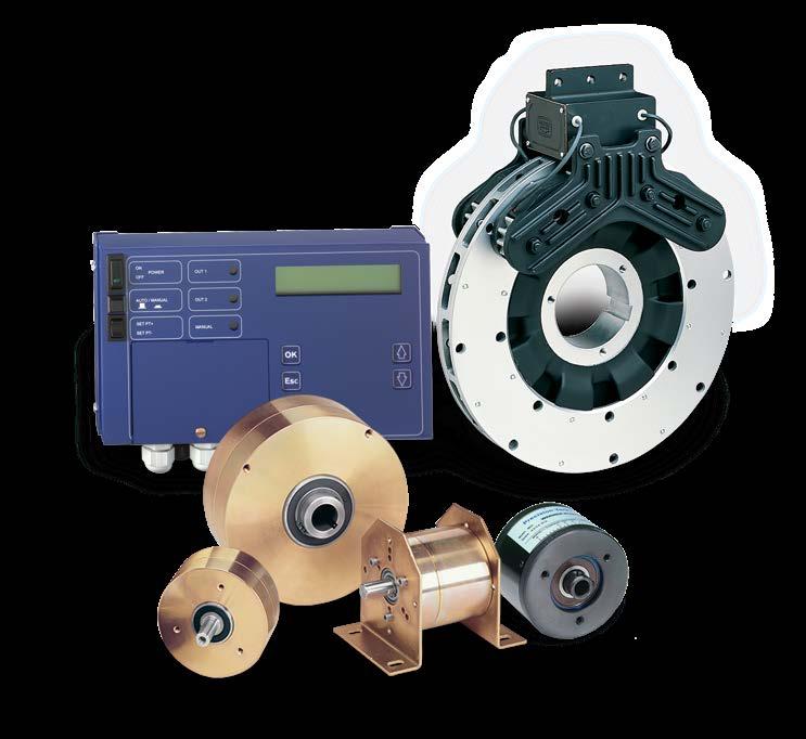

1 A L T R A I N D U S T R I A L M O T I O N Tension Control Systems

2 Applying the appropriated Tension Control will lead you CONTACT WARNER ELECTRIC FOR ANY ASSISTANCE YOU REQUIRE
3 Index SYSTEM CONFIGURATIONS 4 System configuration 1 4 System configuration 2 4 System configuration 3 5 Open loop solutions 6 Closed loop solutions 7 Pages TENSION CONTROL IN OPEN LOOP 8 I.a - Manual setting by pot. 8-9 I.b - Manual setting by following arm 8-9 II - Automatic setting by diameter reading III - Automatic setting by diameter reading with additional functions TENSION CONTROL IN CLOSED LOOP 16 I - Single roll tension control, automatic setting by dancer arm II - Double roll tension control, automatic setting by dancer arm (modular) III - Double roll or splicer tension control, automatic setting by dancer arm (compact) IV - Double roll or splicer tension control, automatic setting by load cells BRAKES AND CLUTCHES RANGE 30 Brakes and clutches models 30 ELECTROMAGNETIC BRAKE TYPE TB 32 Tension brake sizing 31 TB brake characteristics Tension brake for strapping machine MAGNETIC PARTICLE CLUTCHES AND BRAKES 38 MPB, MPC Series BB, BC Series MAGNETIC CLUTCHES AND BRAKES 69 MB, MC Series Applications 76 DATA APPLICATION FORM 77 Tension selection 77 Data application form
4 System configurations Analysing and preparing a project in tension control requires good analysis support. The general block diagrams below are a good representation of any machine generally supporting tension control. We recommend using these diagrams or a part of it in any discussion and correspondence in order to be clear and to avoid possible misunderstandings. The tension area in an unwinding system is defined by places where we want to control this tension SYSTEM CONFIGURATION 1 In single roll unwinding, we have one area tension between A and B. One brake can be easy installed in A. The brake control system selected will be according to the accuracy required: open loop or close loop. A Zone 1 B ZONE 1*, Typical characteristics (unwind) X Tension zone definition: A-B Speed point in B Variable roll rotation speed Variable inertia In general constant tension X Brake system applicable SYSTEM CONFIGURATION 2 Most usual configuration with driving roll,a rewinder and an unwinder.2 separate tension area with tension could be different in X and in Y.Regarding accuracy required we will choice open loop or close loop. In A, unwinding brake, in B motor for the speed and in C clutch or moto-reducer for rewinding. A Zone 1 Zone 3 B C Zone 3*, Typical characteristics (rewind) X Y Tension zone definition B-C Speed point in B Variable roll rotation speed Variable inertia Constant or Taper tension Z Particle brake system applicable 4
5 System configurations SYSTEM CONFIGURATION 3 More complicated machine with intermediary tension area between winder and unwinder.the intermediary area give the line speed. A master-slave system with speed difference in area B/C give required tension. All tension systems must be according the speed line in close loop. A B C Zone 1 Zone 2 Zone 3 D X Y Z IMPORTANT CONSIDERATION In every machine the speed point location must be clearly identified. In general one of driving nip roll is choose to set the linear speed. The machine speed is considered as MASTER function. The tension control, whatever the selected solution, works in SLAVE mode. Practically, the operator sets the machine speed with a simple potentiometer and all tension control system existing on the machine have to follow, keeping the required tension at any speed and during all transitory speed phases. *NOTE : Each zone is individually controlled. Tension may be different in each zone. It is assumed that there is no slipping on the nip roll. ZONE 2*, Typical characteristics Tension zone definition B-C Speed point in B or C Constant roll rotation speed Constant inertia In general constant tension Y Brake system applicable 5
6 System configurations OPEN LOOP CONFIGURATION Working in open loop requires an external reference setting applied to the driver. The torque applied to the unwind roll has to vary according to the diameter of the roll. We don t control acceleration, deceleration and emergency stop as the sensor is blind regarding the band tension. Application needs one sensor only which drives an amplifier without return information for the influence of correction. Sensor Amplifier Brake OPEN LOOP SOLUTION Manual setting by pot. Pot. Amplifier Brake 8 9 Manual setting by following arm Amplifier Brake 8 9 Pot. Automatic setting by diameter reading Amplifier Brake Ultrasonic sensor Additional functions Automatic setting by diameter reading with additional functions Amplifier Brake Ultrasonic sensor Additional functions 6
7 System configurations CLOSED LOOP CONFIGURATION Working in close loop needs one sensor. This one will measure directly or indirectly the band tension. Tension variations detected by sensor are sent to the brake through the control. This action corrects the variation and the new corrected sensor value is sent to the brake and so on. Give a accurate tension regulation during acceleration, deceleration, emergency stop. Sensor Amplifier Brake Position regulation by dancer arm This is an electromechanical system and the building quality for the dancer arm must be verified. The band tension is created by the roll weight and/or by pneumatic actuator which have sensible air exhaust Regulation by load cell This is an electromechanical system and the quality of load cells mounting must be checked. The band influences directly the load cells or loads cells. The load cells choice and the mounting are very important regarding overload during starting or emergency stop Splicer system regulation Our control systems are used with double roll unwinders with splicer. The 2 brakes are always controlled, when one is in regulation, the other has holding function through numeric control range HMCS2000. These controls include loop control with PID, a lot of options and are able to be programmed by PC (via RS line) or by external programmer pocket (visual function). A B The PID function is optimised for one inertia value. The HMCS2000 line is inclusive of an important feature namely the PID correction. Based on the available diameter information you can apply a continuous PID correction. When no information is available, an internal PID change can be programmed. PID relative values P I D Core Typical PID values for TB brakes 100% 50% Diam. Info Each parameter P, I and D can be set individually for the smallest (core) and biggest diameter. As soon as the correct parameters are found for the extreme diameter value, they are stored. The diameter information provided will fix the PID values for the present diameter value. This will allow the system to keep an excellent stability during the whole diameter evolution. In the case where the diameter information is not available we can provide this signal by installing a sonic sensor or by working with internal correction. The external diameter information supplied to the controller will ensure a better precision compensation compared to an internal correction. 7


8 I - Tension control in open loop Working in open loop requires that a torque setting is defined. The choice depends on the machine complexity and the automation required. One important factor that remains is the tension precision. For unwind and rewind systems the diameter ratio will play an important role. Working in open loop also requires special considerations regarding system inertia. a b Manual setting by pot. Manual setting by following arm MAIN APPLICATIONS - ADVANTAGE Setting type Where, When, Why? Advantage By Pot. Diameter reading Cable machine No fast accel/deccel Low roll diameter ratio Operator intervention admitted Low cost solution Easy to start-up Automatic regulation by diameter following arm Manual correction feasible Power supply BTCS252/ VAC 24 VDC and Pot. BTCS254-06/ VDC 0-10 VDC Brake TB Brake MPB, BB Amplifier HMCS2000-DRV2 or 0-1,8 A 0-10 VDC Numeric control BTCS251 8
9 Manual setting by Pot. Potentiometer BTCS254 With strong housing and axis with bearing, the potentiometer BTCS254 is suitable for open or closed loop applications. BTCS mm axis BTCS mm axis Potentiometer 10 k Ohm Shaft material Stainless steel AISI3003 Cover material Plastic reinforced with glass fibre Body material Alu UNI 9002/5 Protection Standard IP54 Operating temperature 0 C / +60 C Cable length 1,5 m Weight 150 g Service manual MC554 Dimensions (mm) ø42 45 ø30 4x M3x90 ø30 ød g6 45 4x M3x90 BTCS 252/255 - Single phase power supply / 24 VDC Dimensions (mm) The Warner Electric switching power supply units of the BTCS252 series are designed and developed for industrial uses where safety, ease of use and reliability are essential. These units comply with the parameters set out by the Low Voltage Directive. The low working temperature at full power operating temperature combined with the use of first quality components ensure high reliability and duration. Specifications Input Output Service manual VAC / 110 VDC, 50/60 Hz 24 VDC, 3 A (BTCS252) and 5 A (BTCS255) MC550 ELECTRICAL AMPLIFIER HMCS2000 HMCS2000-DRV2 1 logic card with 2 individual channels Dimensions (mm) Model Electrical Power supply / Output voltage / input signal current current HMCS2000-DRV VDC 24/48 VDC 0-24/48 VDC/4,5 A Wiring Shielded cable Setting Anti-residual Mounting position Vibrations free, vertically Service manual MC NUMERIC CONTROL BTCS251 (see page 17) Service manual, mounting with Pot. : SM563 9
10 II - Tension control in open loop MAIN APPLICATIONS - ADVANTAGE Setting type Where, When, Why? Advantage Diameter reading The most commonly used solution in open loop No operator intervention admitted Large roll ø ratio Physical reading, no reset Easy to start-up Ultrasonic sensor Power supply BTCS252/ VAC 24 VDC and Brake TB 0-24 VDC 0-10 VDC Brake MPB, BB Amplifier HMCS2000-DRV2 or 0-1,8 A 0-10 VDC Numeric control BTCS251 10
11 Automatic setting by diameter reading ULTRASONIC SENSORS HSCUA-130 HSCUA-140 Model HSCUA-130 HSCUA-140 Power supply 15 to 30 VDC / max 30 ma 15 to 30 VDC / max 30 ma Min. distance 100 mm 400 mm Max. distance 900 mm 2400 mm Accuracy ±1 mm ±1 mm Protection class IP67 IP67 Accessory 5 m cable 5 m cable Service manual MC487 MC488 Dimmensions (mm) ø44,5 14, ,6 4, M12x1 11,2 18,5 31 M12x1 M30x1,5 HSCUA-130 HSCUA-140 BTCS 252/255 - Single phase power supply / 24 VDC Dimensions (mm) The Warner Electric switching power supply units of the BTCS252 series are designed and developed for industrial uses where safety, ease of use and reliability are essential. These units comply with the parameters set out by the Low Voltage Directive. The low working temperature at full power operating temperature combined with the use of first quality components ensure high reliability and duration. Specifications Input Output Service manual VAC / 110 VDC, 50/60 Hz 24 VDC, 3 A (BTCS252) and 5 A (BTCS255) MC550 ELECTRICAL AMPLIFIER HMCS2000 HMCS2000-DRV2 1 logic card with 2 individual channels Dimensions (mm) Model Electrical Power supply / Output voltage / input signal current current HMCS2000-DRV VDC 24/48 VDC 0-24/48 VDC/4,5 A Wiring Shielded cable Setting Anti-residual Mounting position Vibrations free, vertically Service manual MC NUMERIC CONTROL BTCS251 (see page 17) Service manual, mounting with ultrasonic sensor : SM564 11

12 III - Tension control in open loop MAIN APPLICATIONS - ADVANTAGE Setting type Where, When, Why? Advantage Diameter reading The most commonly used solution in open loop Operator intervention admitted Large roll ø ratio Physical reading, no reset Easy to start-up Graphic display for output percentage value Functions control available remote/ manually by operator Ultrasonic sensor signal 0-10 VDC Power supply BTCS252/255 Ultrasonic sensor VAC 24 VDC and HMCS2000-POT-00 Brake TB 0-24 VDC 0-10 VDC Brake MPB, BB Amplifier HMCS2000-DRV2 or OPTION for HMCS2000-DRV2 : BTCS252 Power supply +24VDC 0-1,8 A 0-10 VDC Numeric control BTCS251 12

13 Automatic setting by diameter reading Ultrasonic sensors - Dimensions, see page 11 HSCUA-130 HSCUA-140 Model HSCUA-130 HSCUA-140 Power supply 15 to 30 VDC / max 30 ma 15 to 30 VDC / max 30 ma Min. distance 100 mm 400 mm Max. distance 900 mm 2400 mm Accuracy ±1 mm ±1 mm Protection class IP67 IP67 Accessory 5 m cable 5 m cable Service manual MC487 MC488 Ultrasonic Diameter Sensing HMCS2000-POT-00 A simple, analogue, open loop torque control. Power supply 24 VDC / Internal consumption 150 ma. Adjustable maximum level of the output signal relatively to the ultrasonic input level. Graphic display of the output level full screen equal 10 VDC. FAST STOP, HOLD and BRAKE OFF can be activated either through the front switches or through the terminal bloc. FAST STOP and HOLD levels are adjustable via potentiometer. FAST STOP: a ratio of 1 to 10 times to OPERATING LEVEL OPERATING LEVEL: maximum 10 VDC divided by the FAST STOP ratio. HOLD: output level adjustable between 0 and 10 VDC To be used ONLY with scalable ultrasonic sensors type HSCUA-130 (0,9 m) or HSCUA-140 (2,5 m) Service manual : MC520 Mounting and dimensions (mm) Overall dimensions maximum: Height 160 mm Width 95 mm Depth 75 mm Weight 0,350 kg ELECTRICAL AMPLIFIER HMCS2000 HMCS2000-DRV2 1 logic card with 2 individual output channels Dimensions (mm) Model Electrical Power supply / Output voltage / input signal current current HMCS2000DRV VDC 24/48 VDC 0-24/48 VDC/4,5 A Wiring Shielded cable Setting Anti-residual Mounting position Vibrations free, vertically Service manual MC POWER SUPPLY BTCS252/255 (see page 15) NUMERIC CONTROL BTCS251 (see page 17) Service manual, mounting with 0-10 V signal : SM571 13

14 III - Tension control in open loop MAIN APPLICATIONS - ADVANTAGE Setting type Where, When, Why? Advantage Diameter reading The most commonly used solution in open loop Operator intervention admitted Large roll ø ratio Physical reading, no reset Easy to start-up Particle brake current controled Cheaper solution Ultrasonic sensor Ultrasonic sensor signal 0-10 VDC or Pot. 10 K Ohm 0 10 V signal 0-2 A Power Supply BTCS252/255 Brake MPB / BB Brake TB Regulator BTCS250-C 24 VDC 90 / 264 VAC Ultrasonic sensor Ultrasonic sensor signal 0-10 VDC or Pot. 10 K Ohm 0-10 V signal 0-2 A 115 / 230 VAC Brake MPB / BB Regulator BTCS250-T Brake TB

15 Automatic setting by diameter reading Ultrasonic sensors - Dimensions, see page 11 HSCUA-130 HSCUA-140 Model HSCUA-130 HSCUA-140 Power supply 15 to 30 VDC / max 30 ma 15 to 30 VDC / max 30 ma Min. distance 100 mm 400 mm Max. distance 900 mm 2400 mm Accuracy ±1 mm ±1 mm Protection class IP67 IP67 Accessory 5 m cable 5 m cable Service manual MC487 MC488 BTCS Current regulator power supply for particle brakes The BTCS250 card was designed especially for controling particle brakes and for increasing their yield. In fact, this permits complete elimination of residual magnetism in the powder and therefore it is possible to work in low torque ranges without limits. The components used are professional type and this assures absolute reliability over time. Its limited size facilitates wall mounting. Connection is easy and is done via 10-pole connector fastened to the terminals with screws. Specifications Dimensions (mm) Power supply BTCS250-C Power supply BTCS250-T Input Output BTCS250-C BTCS250-T Service manual 28 VAC or 24 VDC 110/230 VAC 50/60 Hz 0-10 VCC from Pot. 10K 0-2 A modulated PWM Only card Card with transformer MC BTCS250-C BTCS250-T BTCS 252/255 - Single phase power supply / 24 VDC The Warner Electric switching power supply units of the BTCS252 series are designed and developed for industrial uses where safety, ease of use and reliability are essential. These units comply with the parameters set out by the Low Voltage Directive. 55 The low working temperature at full power operating temperature combined with the use of first quality components ensure high reliability and duration. Warner Electric switching power supply units comply with EMI standards. The BTCS252 series with VAC input has no ignition problems at full load even with low mains voltage and therefore suitable for critical supply mains. This series very compact and has an IP 20 degree of protection against incidental contacts according to IEC 529. All the functions are located on the front panel and marked with IEC symbols. Specifications Input VAC / 110 VDC, 50/60 Hz Output 24 VDC, 3 A (BTCS252) and 5 A (BTCS255) Service manual MC

16 I - Tension control in closed loop BTCS251 is a digital controller that can be used in both open or closed loop. The brake driver is included and supply current regulation especially for powder brakes. One 3 digit display permit to follow signal variations. MAIN APPLICATIONS - ADVANTAGE Setting type Where, When, Why? Advantage Dancer arm Unwinders Printing machines Intermittent or continuous function Adapted to powder brakes Output PWM included Digital inputs Numeric with micro-processor Accel / decel machine with separated PID Can drive motor or pneumatic brake Sensor BTCS254 Dancer arm Numeric control BTCS251 Brake MPB / BB A Brake TB Power supply BTCS252/ VDC 90 / 264 VAC 16

17 Automatic setting by dancer arm BTCS251 - Numeric control This device integrates a microprocessor control function and the power output to control the electromagnetic powder brakes. Equipped with only 3 push buttons for calibration and programming and one display with a 3 digit reading, it has been designed to be mounted on a DIN rail inside customers electrical control panel. The compact size, simple installation and easy to use make the instrument extremely flexible. The 24 VDC digital inputs can be easily interfaced with the instrumentation running the machine logic (PLC). The type of input and output electrical signals can be chosen via a keyboard by the system designer and the P.I.D. control logic results in high performance precision control. The unit has been designed specifically for machines utilising a dancer roll and magnetic particle brake however it can also be used with pneumatic brakes or motors, on unwind or rewind applications and with amplified load cells. Applications Spécifications Supply Power with particle brake: Power with pneumatic brake or motor: Regulated analog output 24 VDC / 18 VCA 50 W max. 6 W max. 0-10V/-5+5V/4-20 ma selectable via keyboard Analog output 0-10V PWM output 24VDC, 1,8 A max Analog input keyboard selection 0-5V/0-10V/0-20 ma Digital input 24 VDC Working temp C Weight 180 g Standard approval CE/UL Mounting Rail DIN Service manual MC553 Torque control with DANCER ROLL -- Mode 001 Dimensions ,5 21, ,5 90 8, Speed control with DANCER ROLL - Mode 02 Torque control wit LOAD CELLS - Mode 00 17

18 I - Simple tension control in closed loop If your machine requires a very accurate web tension control, then you need to work in closed loop. An important unit in the loop is the sensor. Several possibilities are offered. The choice now depends on the kind of machine you are building, the mechanical construction and the max tension value you desire to control. MAIN APPLICATIONS - ADVANTAGE Setting type Where, When, Why? Advantage Dancer arm Printing machines Intermittent function Flying splice need Absorb tension peak Can act as store Easy flying splice Accel / decel machine phase well absorbed Flexibility Sensor HMCS605-E2 Brake TB Dancer arm 110/230 VAC Analogue Control HMCS202-E1 Brake MPB VDC Additional functions Brake open Emergency stop Drift stop(stop integral term of PID) Gain change 18

19 Automatic setting by dancer arm ROTARY SENSOR HMCS605-E2 (see pages 20 and 21) ANALOGUE CONTROL HMCS202-E1 HMCS202-E1 HMCS202-E54 HMCS202-EC1 Standard execution Standard IP54 protected Open frame execution Technical characteristics valid for 3 executions Range - Values Comments Power supply VAC selectable Open front face to access Output current capability Max 2, 5 Amps, short circuit protected Able to power 2 TB in parallel User settings Loop gain Front face potentiometer Offset torque Front face potentiometer Output voltage brakes 0-24 VDC Compatible all elec. Warner Electric Housing Metal rugged housing Only HMCS202-E1 and E54 Loop gain 2 adjustable range selection Can be change during operation Accessories HMCS-KIT1, 2, 3, 5 and 6 See details on page 21 Sensor compatible Dancer arm with HMCS605-E2 See details on pages 20 and 21 Service manual MC403 Technical information HMCS202 control is based on classical and fixed PID terms. The loop gain can be set on front face potentiometer. Due to the fixed PID terms, its use is limited in terms of roll diameter ratio. One input is provided to change the loop gain and has to be used when diameter ratio exceeds 8. To ensure proper operation it is important to wire the function Drift Stop. This function releases the Integral term as soon as the machine runs. Dimensions (mm) ,5 73 MCS 202-E POWER BRAKE LOOP GAIN TORQUE OFFSET 14,3 ø65 19

20 Automatic setting by dancer arm ROTARY SENSOR HMCS605-E2 A position sensor is used in 2 possible ways: To detect dancer moving in the closed loop installation working on dancer principle. To sense the diameter of the roll to operate open loop control or make PID compensation in closed loop installation. Sensor HMCS605-E2 is ideal for easy mounting. It is encapsulated in rugged metal housing preventing mechanical shocks. Furthermore it is provided with built in switch in order to change the signal output polarity. TB brake HMCS605-E2 Power supply 10 to 30 VDC / 30 ma (or ± 5 to 15 VDC) Max. detection angle 200 or ± 100 Sensitivity 2,5 mv / V / Service manual MC483 Dimensions (mm) Mounting 50, min 47 / max Coupling ø38,1 57 ø6,35 3 x x ø ,9 14,2 ø6,5 38,1 31,6 20
21 Automatic setting by dancer arm HMCS605-E2 - MOUNTING KIT The HMCS202-Exx is designed to work with dancer arm principle. Usually the sensor is a rotary type. Warner Electric sensor HMCS605-E2 are delivered without mounting kit. Mounting kit comprises of CABLE WITH CONNECTOR(S), COUPLING, MOUNTING BRACKETS and all necessary SCREWS. Various KITS have various lengths of cable and cable with or without connector at control end side. HMCS2000 line requires free leads (HMCS2000 control line is provided with terminal block). HMCS202-Exx requires a connector (HMCS202-Exx is provided with the connector). Old kit 3 wires New kit 4 wires Cable length 1 or 2 Compatibility Wiring connectors HMCS-KIT1 HMCS-KIT1A 3 m 2 HMCS202-E1 A HMCS-KIT2 HMCS-KIT2A 3 m 1 HMCS2000-ECA/CTDA B HMCS-KIT3 HMCS-KIT3A 4,5 m 2 HMCS202-E1 A HMCS-KIT4 HMCS-KIT4A 4,5 m 1 HMCS2000-ECA/CTDA B HMCS-KIT7 HMCS-KIT7A 6 m 2 HMCS202-E1 A HMCS-KIT8 HMCS-KIT8A 8 m 1 HMCS2000-ECA/CTDA B ELECTRICAL CONNECTIONS A (New kit) Shield BROWN SIGNAL /1 0V /2-15VDC (0V) /3 +15VDC /4 YELLOW GREEN WHITE MALE CONNECTOR Front view FEMALE CONNECTOR Front view B (New kit) -15VDC (0V) /3 Shield BROWN 0V /2 YELLOW SIGNAL /1 +15VDC /4 GREEN WHITE MALE CONNECTOR Front view FEMALE CONNECTOR Front view 21

22 II - Double tension control in closed loop (modular) HMCS2000-ECA is a digital controller that can be used in both open or closed loop. Operation in open and closed loop is also possible. It is mainly destined for OEM application. The programming tool is detachable. Sensor, sensor mounting kit, display are available as options. The unit has to be powered with 24 VDC. MAIN APPLICATIONS - ADVANTAGE Setting type Where, When, Why? Advantage Dancer arm Printing machines Intermittent function Flying splice need Absorb tension peak Can act as store Easy flying splice Accel / decel machine phase well absorbed Flexibility Sensor HMCS605-E Dancer arm Brake TB VDC Amplifier HMCS2000-DRV2 9 Memory card HMCS2000-CRD2 Brake MPB Controller HMCS2000-ECA 0-10 VDC Hand Programmer HMCS2000-PRG HMCS2000-WIN01 programme 22


23 Automatic setting by dancer arm POWER SUPPLY BTCS252/255 and HMCS2000-DRV2 (see page 9) ROTARY SENSOR HMCS605-E2 (see pages 20 and 21) CONTROLLER HMCS2000-ECA Digital controller - 2 channels Main Characteristics 24 VDC power supply unit PID parameters setting on line Automatic adaptation for PID parameters, splicing logic included Opto isolation for input and output Compatible PLC Automatic sensor scaling and output sensor information Programming easy by pocket keyboard or PC(Windows) Available in open loop as calculator 2 analogic input, 2 output channels Plugable memory card Three language available Most dedicated for unwinding and rewinding with electromagnetic brakes and clutches. Service manual : MC514 BTCS232FM - RS232 SERIAL CABLE The BTCS232FM cable is specially adapted to connect MCS2000 range controls to PC. Service manual : SM374 HMCS2000-PRG - HAND PROGRAMMER 4 command keys only 2 x 16 characters display Menu in 3 languages Connectable and disconnectable during operation Supply by control HMCS 2000-EC HMCS2000-CRD2 - MEMORY CARD All setting data saved. It allows a quick loading operation on new machine or on running machine to optimise. Memory for 2 different programs Plugable on line in HMCS2000-ECA unit HMCS2000-WIN01 PROGRAMME The program can modify the running setting by this software running with: Windows 95/98/XP/
24 III - Double tension control in closed loop (compact) The command unit HMCS2000-CTDA is a complete solution with power supply and programmer display integrated. There are 2 software version available. See technical data below MAIN APPLICATIONS - ADVANTAGE Setting type Where, When, Why? Advantage Dancer arm Printing machines Intermittent function Flying splice need Absorb tension peak Can act as store Easy flying splice Accel / decel machine phase well absorbed Flexibility Sensor HMCS605-E Brake TB Dancer arm Memory card HMCS2000-CRD Brake MPB VDC Amplifier HMCS2000-DRV2 9 Controller HMCS2000-CTDA VDC HMCS2000-WIN01 programme 24
25 Automatic setting by dancer arm POWER SUPPLY BTCS252/255 and HMCS2000-DRV2 (see page 9) ROTARY SENSOR HMCS605-E2 (see pages 20 and 21) BTCS232FM - RS232 SERIAL CABLE (see page 23) CONTROLLER HMCS2000-CTDA20 Specifications Main features Three mounting possibilities Software password protected Scrolling menu program Multipurpose application RS232 communication Two ouput channels Automatic sensor scaling Programmable output configuration Output sensor information External set point change Automatic or imposed PID correction All features requested for tension control Plugable memory card Variable tension value to prevent telescopic effect on unwinding CTDA-22 Service manual : MC525 Input power supply Analogue inputs Two analogue inputs Analogue outputs Two controlled channels Open loop signal Digital inputs Set point change + Set point change Set point change ± Gain multiplier Output limitation ABC binary combination ABC inputs synchronisation Stop integral form Digital outputs Sensor level indication Other outputs Power supply sensor Power supply Voltage reference VAC selectable 0-10 VDC ± 10 VDC, 0-20 ma 0-10 VDC active low active low front face switch active low active low active low active low active low Two binary outputs ± 15 VDC / 100 ma ± 5 VDC / 100 ma 24 VDC + 10 VDC / 10 ma HMCS2000-CRD2 - MEMORY CARD All setting data saved. It allows a quick loading operation on new machine or on running machine to optimise. Memory for 2 different programs Plugable on line in HMCS2000-ECA unit HMCS2000-WIN01 PROGRAMME The program can modify the running setting by this software running with: Windows 95/98/XP/


26 IV - Double tension control in closed loop The command unit HMCS2000-CTLC is a complete solution with power supply and programmer display integrated. There are 2 software version available. See technical data below MAIN APPLICATIONS - ADVANTAGE Setting type Where, When, Why? Advantage Load cell Slitter, Sheeter and Coater For heavy material Limited room No fast accel/decel Tension peak accepted Direct tension measure Mechanically well integrated No moving part One or two load cells Memory card HMCS2000-CRD2 Brake TB Brake MPB VDC Controller HMCS2000-CTLC VDC 0-24 VDC 24 VDC Amplifier HMCS2000-DRV2 9 HMCS2000-WIN01 Programme 26

27 Automatic setting by load cell POWER SUPPLY BTCS252/255 and HMCS2000-DRV2 (see page 9) BTCS232FM - RS232 SERIAL CABLE (see page 23) CONTROLLER HMCS-2000-CTLC-20 Specifications Main features Three mounting possibilities Software password protected Scrolling menu program Multipurpose application RS232 communication Two ouput channels Automatic sensor scaling Programmable output configuration Output sensor information External set point change Automatic or imposed PID correction All features requested for tension control Plugable memory card Variable tension value to prevent telescopic effect on unwinding CTLC-22 Service manual : MC516 Input power supply Analogue inputs Two analogue inputs Analogue outputs Two controlled channels Open loop signal Digital inputs Set point change + Set point change Set point change ± Gain multiplier Output limitation ABC binary combination ABC inputs synchronisation Stop integral form Digital outputs Sensor level indication Other outputs Power supply sensor Power supply Voltage reference VAC selectable 0-10 VDC ± 10 VDC, 0-20 ma 0-10 VDC active low active low front face switch active low active low active low active low active low Two binary outputs ± 15 VDC / 100 ma ± 5 VDC / 100 ma 24 VDC + 10 VDC / 10 ma HMCS2000-CRD2 - MEMORY CARD All setting data saved. It allows a quick loading operation on new machine or on running machine to optimise. Memory for 2 different programs Plugable on line in HMCS2000-ECA unit HMCS2000-WIN01 PROGRAMME The program can modify the running setting by this software running with: Windows 95/98/XP/

 HFM..-AC HFM.")
28 Load cells The FOOT MOUNTED LOAD CELL is the ideal solution to retrofit machines or for heavy tension measurement. The foot mounted model has to be installed with a pillow block type ball bearing supporting the sensing shaft. HFM01A... and HFM are only differenciated by the physical dimensions. FOOT MOUNTED TYPE FM01A and FM02- Foot mounted load cells are available in two versions: With incorporated amplifier : HFM..-AC Without amplifier : HFM..-C AC = amplifier and connector on the load cell body C = connector on load cell body Specifications (all HFM series) HFM..-AC HFM..-C Power supply ±12 to ±15 VDC ± 5 VCC or +10 VDC Sensitivity 0-5 VDC, nominal load 10 mv, nominal load Rating N Connections Cable supplied Permitted overload - Compression 150 % - Extension 120 % Radial permitted force 50% Dimensions See mounting instructions ref. MC480 Mounting See recommendations on page 29 Service manual MC480 AVAILABLE MODELS / CAPACITY Nom. load 100 N 250 N 500 N 1000 N 2500 N 5000 N N HFM01A AC -250-AC -500-AC AC AC AC HFM01A C -250-C -500-C C C C HFM AC HFM C AC C HMCS2000-IS - Load Cell Interface The interface sensor will sum and amplify the input signals from two load cells, and can be used with a number of different load cells. The interface should be positioned close to the load cells to ensure that no noise is injected into the low voltage signal before it is amplified. Specifications Input power / Output power Input supply: +24 VDC, ±10%, 300 ma Analog inputs 2 load cell input: any voltage between 20 mv and 10 VDC 5 K Ω input impedance Ultrasonic input: 0-10 VDC, delta mon. of 1 V 10 K Ω input impedance max. gain: inputs for line speed: 0-10 VDC, 10 K Ω impedance Analog outputs (short circuit protected) Calibrated load cell/ ultrasonic-sensor output: 0-10 VDC, 10 ma max. Power for ultrasonic sensor: +24 VDC Voltage reference: 10 VDC, 10 ma Service manual MC521 28

29 Load cells END SHAFT LOAD CELLS are normally used in new machines designed with the possibility to place the load cell directly on the sensing roll. The end shaft version offers the advantage of being able to easily place the load cell in any tension resultant direction. The HES model exists in two versions differenciated with the diameter of ball bearing which has to be placed in. All end shaft load cells are based on the Wheatstone bridge principle. They have no built in amplifier. They are delivering a signal which is proportionnal to the voltage supply and tension applied. It is important to respect the measurement direction referenced on the load cell body (normally an arrow indicates the sensitive direction). HES LOAD CELL FEATURES Power supply Sensitivity Rating Connections Mechanical overload Dimensions Mounting Service manual HES01-40C and HES02-52C 10 to 15 VDC / 40 ma (±5 VDC in Warner Electric control) 2 mv / V supply at nominal load 1 mv / V supply for 50 and 150 N models N 5 m shielded cable supplied Max 150 % in any direction See mounting instructions ref. MC481 and MC482 See recommendations below MC481 and MC482 AVAILABLE MODELS / CAPACITY Nominal load 150 N 250 N 500 N 1000 N 2000 N HES C C C C C HES C C C C LOAD CELLS SIZING - MOUNTING RECOMMENDATIONS Please keep this principle in mind: the load cell installed is destined to measure the WEB TENSION and not other constraints applied to it. Wrapping Angle 240 min. Take the following points into consideration before selecting, sizing and installing material components. Load cells location should be vibration free. Vibrations will decrease quality measurement. The sensing shaft fitted on or in has to be very well balanced. Unbalanced shaft will create measurement oscillation, causing variations in control quality. Adapted ball bearing have to be used to avoid original stress on load cell (self-aligning ball bearing). Respect a reasonable sensing shaft weight/web tension measure ratio. Less than 1. Do not oversize the load cell respect to your calculation. Max admitted factor 3, recommended 1,5. Respect a minimum wrapping angle on load cell. Min = 180. So far as it is possible, use load cell in compression, with web tension effect in same direction as the weight of shaft. 29


30 Tension brakes and clutches range Brake and clutch types Series Main characteristics Torque range Pages Electromagnetic brakes TB Monodisc 24 VDC power supply 0,5-300 Nm Electromagnetic brakes TBM Monodisc 24 VDC power supply 10 Nm Magnetic particle brakes MPB BB Completely packaged and enclosed unit Shaft output or bore 24 or 90 VDC power supply 0, Nm Magnetic particle clutches MPC BC Completely packaged and enclosed unit Both end shaft output or bore 24 or 90 VDC power supply 0, Nm Permanent magnetic brakes MB Completely packaged and enclosed unit Shaft output Manual setting 0-33 Nm Permanent magnetic clutches MC Completely packaged and enclosed unit Bore output Manual setting 0,07 Ncm - 33 Nm
.")
31 Tension brake sizing Two important parameters are used in brake selecting: Max. torque requirement Max. thermal power to be dissipated These two values are determined by the application (see calculation example on pages 78-79). ELECTROMAGNETIC BRAKE TYPE TB SELECTION TB brake selection is based on two values : Max torque need (Nm) on the brake *Max brake rotation speed for the max torque (rpm) * As the curve given for TB selection takes the power dissipation into account, this value is used. T max T max = torque needed at the brake for the max tension in material and the max roll diameter - taking any gear ratios into account. Selection point N max = brake rotation speed for the max linear speed and the max roll diameter taking any gear ratios into account. N max Note : the constant tension in the web gives a constant power on the brake. However, we make the selection for the max torque (then at full roll diameter) because it s the moment where the brake has the least natural cooling. Gear box Speed Brake Torque 31

32 TB brake selection The table (pictured below left) illustrates the selection of the correct TB brake. The table on the right determines the maximum torque provided by the brake when nominal voltage is applied. After selection you can consult the complete brake characteristics and dimensions on pages 34 to 35. Dynamic braking torque TB170 - TB1525 Maximum braking torque (emergency stop) TB170 - TB Torque M d [Nm] TB 1000 TB 825 TB 500 TB 1525 TB1225 Brake torque M B [Nm] TB 1525 TB 1225 TB 1000 TB 825 TB TB TB ,5 1 0,8 TB TB 260 0,6 0,4 0,3 TB ,8 TB 170 0, Brake n (rpm) 0, Brake n (rpm) 32
33 TB brake characteristics TB units are assembled using various parts described below. Main components of the brake are armature and magnet. Additional parts are offered to provide for ease of mounting. Part TB170 TB260 TB425 Part TB500 D = 46 mm D = 69 mm D = 111 mm 1 Armature hub* B B B Armature K B B Magnet 24V K K K R = 110 Ω, 20 C R = 60 Ω, 20 C R = 76 Ω, 20 C 4 Terminals Wires B B * Prebored ** Indicate bore and keyway D = 130 mm 1 Taperlock bushing** B180-xxxx-xxxx 2 Armature hub K Armature B Drive pins K x 5 Magnet IM 24V B Terminals B Magnet OM 24V B Conduit box K Part TB825 TB1000 TB1225 TB1525 D = 215 mm D = 259 mm D = 316 mm D = 395 mm 1 Taperlock bushing** B180-xxxx-xxxx B180-xxxx-xxxx B180-xxxx-xxxx B180-xxxx-xxxx 2 Armature hub B B B B Armature B B B B Drive pins B B B B x 3 x 4 x 4 x 4 Magnet IM 24V B B B B R = 20 Ω, 20 C R = 20 Ω, 20 C R = 22 Ω, 20 C R = 20 Ω, 20 C 5-1 Terminals B B B B Magnet OM 24V B Conduit box K K K K
34 øg øq TB brake characteristics All TB brakes are rated at 24 VDC nominal. When selection is correct the voltage on the brake should be approximately 12 VDC for your maximum parameters used in calculation. All TB brakes are able to work for short periods of time (less than 10 seconds) in the VDC range, for example in machine deceleration or in emergency stop. Technical data and dimensions TB170, TB260, TB425 TB500 IM TB825 IM, TB1000 IM, TB1225 IM B 1,6 A C E B ød øh øl K øs ød øm øl K 3,2 øg øn øp ød øh øm øl K 2,4 øg øn 3,2 øp øs øq øs øq 3,0 0,4 A E ø9,52 0,025 1,2 T B F A C E TB500 OM TB825 OM, TB1000 OM, TB1225 OM Size TB170 TB260 TB425 TB500 TB825 TB1000 TB1225 TB1525 M d [Nm] 0,8 4 16, M d min [Nm] 0 0,08 0,16 0,2 0,5 1,1 2 3 n max [rpm] I 24V = [A] 0,22 0,40 0,32 1,010 1,177 1,224 1,076 1,212 P Continu [kw] 0,015 0,030 0,060 0,100 0,200 0,360 0,520 0,810 P* Alternativ [kw] 0,022 0,045 0,100 0,180 0,360 0,650 0,950 1,580 R 20 C [Ω] ,8 20,4 19,6 22,3 19,8 t b [s] 0,020 0,040 0,080 0,052 0,112 0,152 0,290 0,310 Inertia [kgm 2 ] , , ,022 0,041 0,095 0,213 Mass [kg] 0,180 0,650 1,800 2,3 8, ,5 A [mm] 30,5 48, B [mm] ,5 30,5 30,5 30,5 C [mm] , ød [mm] E [mm] 20, ,5 30,5 33,5 36,5 41,5 44,5 * Alternativ duty based on 30 minutes ON and 30 minutes OFF. 34
35 TB brake characteristics TB1525 IM TB B 1/2-13 UNC-3B ø12, ød øm øh øl 2,4 K øg øn øp 3,5 30 9,5 M øu Steel < 0,2 % C A E C ø12, Non magnetic Size TB170 TB260 TB425 TB500 TB825 TB1000 TB1225 TB1525 F [mm] , øg [mm] 19,5 +0, øh [mm] 15,9 30,1 31, ,5 K* [mm] 10,3 17,5 22, , øl max [mm] øm ±0,025 [mm] ,42 90,49 133,4 149,3 215,9 3 x x x x 90 4 x 90 øn ±0,05 [mm] ,40 88,93 136,55 161,95 228,60 øp (for screw) [mm] , ,6 184,1 247, x M4 6 x M8 6 x M8 6 x M8 12 x M8 øq -0,05 [mm] 61,9 88,9 142,47 165,10 247, øs (for screw) [mm] 54 79, ,2 225, x M4 4 x M4 4 x M6 4 x M10 4 x M T [mm] øu [mm] * Reverse mounting of taperlock bushing is possible 35

36 Tension brake for strapping machine Specially designed for strapping machine, the electromagnetic brake TBM10 is adjustable for the different kind of plastic film. Mounted on the intermediate roller, it will tighten the plastic film and will permit a perfect strapping. TBM BRAKE PALLET PLASTIC FILM ROLLER TBM SIZE 10 Heat dissipation torque Brake torque M d (Nm) n (rpm) M d (Nm) n (rpm) 36
37 Tension brake for strapping machine TBM SIZE 10 ➁ VAR 03 T ➀ ➂ ø 5.5 ø 81 D H8 ø 42 ø 90 ø 100 h9 P D min = 8 mm with standard keyway D min = 13 mm with standard keyway VAR 04 3 pins on ø ø 0, H8 8.3 ➃ T ➀ ø 41 U max : 24 VDC - P 20 C = 10,8 Watts 26 Keyway according to : ISO R773 / BS 4235 / NFE / tolerance P9 Part TBM SIZE 10 1 Inductor 24VDC B Armature VAR03 B Hub prebored ø7,5 B Hub ø12 H8 + Keyway 4 P9 B Armature VAR04 B

38 Magnetic particle clutches and brakes Accurate torque control with instantaneous engagement! Warner Electric Precision Tork magnetic particle clutches and brakes are unique because of the wide operating torque range available. Torque to current is almost linear and can be controlled very accurately. The unique features of the magnetic particle clutches and brakes make them ideal for : tension control load simulation cycling/indexing soft starts and stops Specials are our business Special Shaft Configurations Customer specified shaft configurations for easy machine mounting and retrofitting. Wash Down Environment Stainless steel units available for extreme environments. Special Torque Maximum torque configurations to meet customer specifications. Features and Benefits Torque independent of slip speed Torque is transmitted through magnetic particle chains which are formed by an electromagnetic field. The torque is independent of slip speed, depending only on circuit current, and is infinitely variable from 0 (disengaged) to rated torque. Precise engagement Precision Tork magnetic particle clutches and brakes engage to transmit torque with speed and precision. Response of the particles to the field is virtually instantaneous, providing perfectly controlled, jerk-free engagement. Customer specified engagement Engagement time may be very gradual or extremely fast. The frequency and torque of the engagement/disengagement sequence is limited only by the capabilities of the control circuitry. No wearing parts There are no friction surfaces to grab or wear, and the units are not affected by changes in atmospheric or other environmental conditions. Efficient/Compact design High torque to size ratio and low consumption of electric power. Versatile mounting Convenient bolt circle for easy mounting. Mounting brackets available for all sizes. Brakes are available with solid shafts and through bore. Can be mounted horizontally or vertically to solve virtually any motion control requirement. Modular Customised products Interchangeable with industry standard sizes

39 Design and operation Completely packaged and enclosed unit. Easy to install Stainless steel hardware Low current coil generates magnetic field Zinc dichromate plating on all steel surfaces Extremely long life spherical magnetic particles Magnetic powder cavity Stainless steel input shaft Convenient pilot and mounting bolt pattern New and unique dual seal design Operating Principles The magnetic particle unit consists of four main components: 1) Housing 2) Shaft/disc 3) Coil 4) Magnetic powder The coil is assembled inside the housing. The shaft/disc fits inside the housing/coil assembly with an air gap between the two; the air gap is filled with fine magnetic powder. Engagement Power input (DC) Stationary field Magnetic-flux path Magnetic particles Rotor Cylinder Seal Percent of rated torque Torque current curve When DC current is applied to the magnetic particle unit, a magnetic flux (chain) is formed, linking the shaft/disc to the housing. As the current is increased the magnetic flux becomes stronger, increasing the torque. The magnetic flux creates extremely smooth torque and virtually no stick-slip. Disengagement Field coil Output shaft Input shaft Percent of rated current When DC current is removed the magnetic powder is free to move within the cavity, allowing the input shaft to rotate freely.
40 Magnetic particle clutches and brakes Selection Sizing To properly size magnetic particle clutches or brakes the thermal energy (slip watts) and torque transmitted must be considered. If thermal energy and torque are known for the application, select the unit from the charts to the right. Speed V (RPM)* = Velocity (m/min) π ø coil** (m) * In rewind applications the motor RPM should be higher (10%) than the fastest spool RPM. ** In applications with the web running over a pulley or in a nip roll application use the pulley diameter as the roll diameter. Thermal Energy (slip watts) 1- When a brake or clutch is slipping, heat is generated. Heat is described in terms of energy rate and is a function of speed, inertia, and cycle rate. For continuous slip applications, such as tension control in an unwind or rewind application slip watts are calculated using the following formula: Slip Watts = 0,103 torque (Nm) speed (RPM) 2- For cycling applications heat is generated intermittently, and is calculated using the following formula: Slip Watts = 0,00077 J (kgm 2 ) speed (RPM)2 f cycle min The average heat input must be below the clutch or brake s heat dissipation rating. If the application generates intermittent heat dissipation, use the average speed for the thermal energy (slip watts) calculations. Torque 1- Tension applications calculate torque as a function of roll radius and tension. C (Nm) = T (N) D 2 2- Soft/controlled stopping applications calculate torque as a function of inertia, speed and desired time to stop the load. C (Nm) = J (kgm2 ) N (RPM) 9,55 Time (s)
41 Magnetic particle clutches and brakes Quick Selection Charts MPB2 / MPC2 MPB15 / MPC Heat dissipation : 10 watts max Heat dissipation : 20 watts max. Slip (RPM) Slip (RPM) , ,13 0,18 0,22 0,02 0,07 0,11 0,15 0,2 Torque (Nm) 0 0 0,2 0,45 0,67 0,9 1,1 1,35 1,58 Torque (Nm) MPB70 / MPC70 MPB120 / MPC Heat dissipation : 100 watts max Heat dissipation : 140 watts max. Slip (RPM) Slip (RPM) ,13 2,26 3,39 4,51 5,64 6,77 7,9 Torque (Nm) 0 0 2,2 4,51 6, ,3 13,55 Torque (Nm) MPB Heat dissipation : 200 watts max. Slip (RPM) ,4 9 13, ,5 27 Torque (Nm)
42 Magnetic particle clutches and brakes Applications Warner Electric Precision Tork magnetic particle clutches and brakes are the ideal solution for controlling and maintaining torque. If the application is tensioning, load simulation, torque limiting, or soft starts and stops the magnetic particle unit is the preferred torque controlling device. Typical Applications Unwind stand under load cell control Wire Processing (winding, hooking, cutting) Paper/Foil/Film Processing Labelling Applications Textile Processing Load profile simulation on: - Exercise Equipment - Flight Simulators - Healthcare Equipment Life testing on: - Motors - Gears - Pulleys Rewind stand under dancer control - Belts - Chains - Many other Rotating Devices Conveyors Bottle Capping
43 Magnetic particle clutches and brakes Tensioning Magnetic Particle clutches and brakes offer smooth controlled torque for tensioning in both the unwind zone and rewind zone. Torque produced from the magnetic particle clutches and brakes is independent of slip speed, offering a distinct advantage over competing technologies. Since torque can be varied infinitely by varying the input current, the magnetic particle clutches and brakes are ideal in an open loop system. To close the loop in the tensioning system, combine the magnetic particle clutch or brake with a Warner Electric sensor and control, resulting in more precise control of tension. Particle clutches and the MCS2000-CTDA control provide accurate closed loop tension control for rewind applications. Application example: Slip = Velocity π D = 122 π 0.5 Information Full roll ø : 0,5 m required: Tension : 22 N Velocity : 122 m/min Max. torque = = tension full roll ø ,5 2 = 5,5 Nm Heat dissipation = 78 RPM = 0,103 torque slip = 0,103 5,5 78 = 44,46 watts Select a brake that exceeds the maximum torque and thermal energy requirements from Quick Selection Chart MPB70. Particle clutches and the MCS202-E1 control provide accurate closed loop tension control for rewind applications. Application example: Information Core ø : 0,08 m required: Full roll ø : 0,23 m Tension : 22 N Velocity : 90 m/mn Input speed : 500 RPM* Full roll ø Slip = Speed (π D) = 90 (π 0,23) = 125 RPM = Input speed Full roll ø = = 375 RPM Max. torque. = = Tension full roll ø Thermal Energy = 0,103 Torque slip = 0,103 2, = 97,72 watts = 2,53 Nm = Speed (π d) = 90 (π 0,08) = 358 RPM Select a clutch that exceeds the maximum torque and thermal energy requirements from the Quick Selection Chart MPC120. * To maximize tension control and minimize heat generated, select a drive system that will result in an actual input speed as close to, but not less than, 30 RPM greater than the core RPM. In this example, = 388, would be ideal but 500 RPM was more readily available.
44 Magnetic particle brakes - MPB F 305 mm K Both ends A Model: MPB15M WARNER ELECTRIC R G B Both ends Flat or keyway D C E I Specifications Models Max. Drag Rated Resistance Rated Response Response Inertia of Max. heat Max. Weight torque torque voltage current zero with output shaft dissipation speed force force (Nm) (Nm) (VDC) (Ω) (A) (ms) (ms) (kgcm 2 ) (W) (RPM) (kg) MPB2M ,2 0, , , ,45 MPB15M ,7 0, , , ,36 MPB70M ,9 0, , , ,2 MPB120M ,6 0, , , ,45 MPB240M ,1 0, , , ,1 MPB ,4 0, , , ,1 Dimensions (mm) Models Shaft ø Keyway - DIN 6885 Mounting Holes I (h7) (Width x length) K depth MPB2M ,5 flat on 16 3 x M4 on ø 34 equidistant 7 MPB15M x 20 3 x M5 on ø 51 equidistant 7,5 MPB70M x 25,4 4 x M5 on ø 107 equidistant 16 MPB120M x 25,4 4 x M6 on ø 122 equidistant 19 MPB240M x 25,4 4 x M6 on ø 149 equidistant 16,5 MPB flat on 31,8 4 x M6 on ø 150 equidistant 8 Models A Pilot ø B C D E F G MPB2M ,59 19,05-19,03 56,64 29,21 1, ,1 MPB15M ,39 28,59-28,56 77,47 37,08 1,78 21,84 34,29 MPB70M ,23 41,29-41,26 85,6 44,7 2,54 24,89 31,75 MPB120M ,35 41,29-41,26 102,11 55,12 2,54 29,97 38,1 MPB240M ,57 62,01-61,99 118,36 67,31 2,54 37,08 41,91 MPB ,57 62,01-61,99 118,36 67,31 2,54 37,08 41,91
45 Magnetic particle clutches - MPC F 305 mm K Both ends A H INPUT Model: MPC15M WARNER ELECTRIC R G B Both ends Flat or keyway D C E I Specifications Models Max. Drag Rated Resistance Rated Response Response Inertia of Max. heat Max. Weight torque torque voltage current zero with output shaft dissipation speed force force (Nm) (Nm) (VDC) (Ω) (A) (ms) (ms) (kgcm 2 ) (W) (RPM) (kg) MPC2M ,2 0, , , ,454 MPC15M ,7 0, , , ,72 MPC70M ,9 0, , , ,71 MPC120M ,6 0, , , ,98 Dimensions (mm) Models Shaft ø Keyway - DIN 6885 Mounting Holes I (h7) (Width x length) K depth MPC2M ,5 flat on 16 3 x M4 on ø 34 equidistant 12,7 MPC15M x 20 3 x M5 on ø 51 equidistant 12,7 MPC70M x 25,4 4 x M5 on ø 107 equidistant 16 MPC120M x 25,4 4 x M6 on ø 122 equidistant 19 Models A Pilot ø B C D E F G H MPC2M ,59 19,05-19,03 94,74 46,99 1,52 28,46 22,35 22,35 MPC15M ,39 28,59-28,56 132,3 71,12 1,78 42,93 34,3 23,4 MPC70M ,46 41,29-41,26 166,37 93,22 2,54 52,83 34,29 34,29 MPC120M ,35 62,01-61,99 178,31 101,6 2,54 60,96 38,1 34,3

46 Magnetic particle clutches and brakes The magnetic particle unit combines the resilience of a fluid coupling with the locked-in stability of a friction clutch. Torque is transmitted by a specially alloyed dry ferromagnetic powder, it apparent viscosity may be changed by modulation of the field coil current. The units can sustain continuous slip (under maximum heat ratings) at a precise and stable torque value, which is determined by excitation level. Slip between input and output members is not necessary in order to transmit torque, and provided load torque does not exceed the torque for which a unit is excited to transmit, locked-in synchronous operation will take place. Conversely, if load torque exceeds the energised torque level, slip will occur in an absolutely smooth manner at the predetermined torque value. For all practical purposes, static and dynamic coefficients of friction are sensibly equal; also, output torque is independent of speed, or slip speed. Powder performance is unaffected by temperature rise on the working surfaces, and units will, have at all times, a torque directly proportional to current. It should be noted that use of a dry powder rather than a fluid-suspended powder medium promotes consistency and accuracy of torque control. Briefly, the unit include two concentric members, the body or input member containing the field coil, and within it, and separated by a small annular gap, an inner rotor, or output member. The annular gap contains a ferromagnetic powder, which is activated when the coil is energised. The resultant flux which is generated, passed through the powder, causing it to align with the flux path, and thereby creates a driving bond between input and output members, the strength of which is only determined by the value of DC current applied to the coil. Operating characteristics The torque transmitted by powder units is proportional to field current, and is infinitely variable from maximum design rating down to practically zero in all models. Torque/current characteristic curves can vary by 5 % dependent on whether current is increasing or decreasing. This is due to magnetic hysteresis. Torque (Da/Nm) Absorption (A) For all practical purposes torque is independent of speed, either with or without the presence of slip, and can be maintained within an accuracy of 5 % for speeds within the recommended operating range 50 to 2600 RPM. De-energised drag torque due to residual iron circuit magnetism, bearing and seal friction, is less than 1 % of design torque rating for any unit. Response time to torque is determined by field coil inductance to resistance ratio plus a magnetic delay due to eddy current loss. Note: to ensure satisfactory operation, all clutches and brakes must be mounted in horizontal axis. For vertical use, please consult us.
47 Magnetic particle clutches and brakes BRAKE selection When min. roll speed and max. torque are known for the application, select the unit from theses charts. For continuous slip applications, as tension control in an unwind or rewind application, slip watts are calculated using the following formula: Slip Watts = 0,103 max. torque (Nm) min. roll speed (RPM) Torque (Nm) BBR500 BBR250 BBR170-1 BBR120-1 BBR65-1 Torque (Nm) Torque (Nm) BB500 BB250 BB170-1 BB120-1 BB65-1 BB35 BB BBV500 BBV250 BBV170-1 BBV120-1 BBV65-1 Brakes Series BB Speed (RPM) BBR35 BBV35 10 BBR BBV12-1 Brakes Series BBR Brakes Series BBV Speed (RPM) Speed (RPM) 47
 slip speed (RPM) In rewind applications the motor RPM should be higher (10 %) than the fastest spool RPM.")
48 Magnetic particle clutches and brakes CLUTCH selection For continuous slip applications, as tension control in a rewind application, slip watts are calculated using the following formula: Slip Watts = 0,103 max. torque (Nm) slip speed (RPM) In rewind applications the motor RPM should be higher (10 %) than the fastest spool RPM. In applications with the web running over a pulley or in a nip roll application use the pulley diameter as the roll diameter. In rewind application, don t forget to always mount the motor output to the exterior flange of clutch to enable maximum heat dissipation as drawing below. W (Watts) BC500 BC250 BC170-1 BC120-1 BC65-1 BC35 BC12 Clutches Series BC Speed (RPM) W (Watts) BCR BCR250 BCR170-1 BCR120-1 Mounting example for clutches (in line) BCR65-1 BCR35 BCR Output Clutches Series BCR Speed (RPM) 48
49 Magnetic particle brakes Quick selection BRAKES Torque (Nm) Dissipation (W) Page BB BBR BB BBR BB BBR BBV BB BBR BBV BB BBR BBV BB BBR BBV BB BBR BBV BB BBR BBV BB BBR BBV CLUTCHES Torque (Nm) Dissipation (W) Page BC / BCR / BC / BCR / BC / BCR / BC / BCR / BC / BCR / BC / BCR / BC / BCR / XXR = Radiator XXV = Fan BB ±0.1 Ø70 Ø30 Ø x M4, deeph 8 mm equidistant for mounting Supply cable output ø Ø8 h7 Specifications Models BB2 Maximum torque Nm 2 Power dissipation W 35 Voltage V 24 Attention : For a correct use of the brake, the operating temperature must not be more than 70 C Models BB2 Current A 0,8 Resistance at 20 C Ohm 27 Weight kg 0,8 49
50 Magnetic particle brakes BBR Ø Ø50±0.1 Ø130 Ø70 Ø Ø8 h7 3 x M4, deeph 8 mm equidistant for mounting Supply cable output ø51 34 Specifications Models BBR2 BB5 Maximum torque Nm 2 5 Power dissipation W Voltage V Attention : For a correct use of the brake, the operating temperature must not be more than 70 C Models BBR2 BB5 Current A 0,8 1,3 Resistance at 20 C Ohm 27 16,5 Weight kg 1,2 1,8 BB5 Ø ±0.1 Ø66± Ø55 ±0.1 3 x M5, deeph 8 mm on dia. 55 mm equidistant for mounting Supply cable output Ø40g6 30 4H9 2.5 Ø12g6
51 Magnetic particle brakes BBR5 3 x M5, deeph 8 mm on dia. 55 mm equidistant for mounting Ø91 Ø66 ±0.1 Ø55± ± Supply cable output H9 Ø12 g6 Ø160 Ø40 g6 120 Specifications Models BBR5 BB12-1 Maximum torque Nm 5 12 Residual torque Nm - 0,3 Voltage V Current A 1,3 0,9 Attention : For a correct use of the brake, the operating temperature must not be more than 70 C Models BBR5 BB12-1 Résistance à 20 C Ohm 16,5 25 Power dissipation W Weight kg 2,2 2,5 BB x M5, deeph 8 mm equidistant for mounting 6 60 M5 Ø Ø103 ±0.10 Ø55h Ø Ø15H7 Supply cable output
52 Magnetic particle brakes BBR12-1 Supply cable output 3 x M5, equidistant for mounting Ø103 ±0.1 Ø Ø h7 M5 Ø8,6 Ø15H7 49 Specifications Models BBR12-1 BBV12-1 Maximum torque Nm Residual torque Nm 0,3 0,3 Voltage V Current A 0,9 0,9 Attention : For a correct use of the brake, the operating temperature must not be more than 70 C Models BBR12-1 BBV12-1 Resistance at 20 C Ohm Power dissipation W Weight kg 4,3 4,7 Fan tension V - 24 VDC,115/230 AC BBV x M5 equidistant for mounting Fan cable Brake cable 60 ±0,1 Ø103 Ø Ø h7 Ø115 Ø158 15H
53 Magnetic particle brakes BB35 56 ± ± x M5 equidistant for mounting Ø135.5 Ø55 h Ø98 ±0.1 Ø Supply cable output 61.4 ± H7 Specifications Models BB35 BBR35 Maximum torque Nm Residual torque Nm 0,4 0,4 Voltage V Current A 0,9 0,9 Attention : For a correct use of the brake, the operating temperature must not be more than 70 C Modèles BB35 BBR35 Resistance at 20 C Ohm Power dissipation W Weight kg 4,3 7,3 BBR ± x M5 equidistant for mounting Ø135.5 Ø55 h ± Ø98 ±0.1 Ø Supply cable output 17 H7 61.4±0.1
54 Magnetic particle brakes H7 30 BBV35 56 ±0.05 Supply cable output 60 Fan Ø158 Ø135.5 Ø55 h Ø162 Ø Ø ±0.1 6 x M5 equidistant for mounting 17 H Specifications Models BBV35 BB65-1 Maximum torque Nm Residual torque Nm 0,4 0,4 Voltage V Current A 0,9 1 Attention : For a correct use of the brake, the operating temperature must not be more than 70 C Models BBV35 BB65-1 Resistance at 20 C Ohm Power dissipation W Weight kg 6,4 9 Fan tension V 24 VDC,115/230 AC - BB65-1 M5 x x M5 equidistant for mounting D M5 x 20 M5 x Ø75 h Ø144 ± Ø144±0.10 Supply cable output
55 Magnetic particle brakes BBR H M5x20 M5x D h7 30 M5x20 Ø Ø144±0.10 Ø157 3 x M5 equidistant for mounting Specifications Models BBR65-1 BBV65-1 Maximum torque Nm Residual torque Nm 0,4 0,4 Voltage V Current A 0,95 1 Attention : For a correct use of the brake, the operating temperature must not be more than 70 C Models BBR65-1 BBV65-1 Resistance at 20 C Ohm Power dissipation W Weight kg 9,8 8,8 Fan tension V - 24 VDC,115/230 AC BBV x M5 equidistant for mounting Câble frein Câble ventilateur 6 D Ø Ø Ø140 Ø185 Ø144 ± Ø 20H
56 Magnetic particle brakes BB120-1 * 5mm/old ref. BB Ø254 0 Ø233 ± ± ± x ø7 mm equidistant for mounting Ø195± ± ± ±0.10 * M6x20 10 H10 M6x20 Scale 2 :1 7 ±0.10 M6x Ø28 H Ø ± ± ± Ø195 ±0.10 Ø 214g6 M6x20 Scale 2 : ±0.10 Supply cable output Specifications Models BB120-1 BBR120-1 Maximum torque Nm Residual torque Nm 0,6 0,6 Voltage V Current A 2 2 Attention : For a correct use of the brake, the operating temperature must not be more than 70 C Models BB120-1 BBR120-1 Resistance at 20 C Ohm Power dissipation W Weight kg BBR120-1 * 5mm/0ld ref. BBR120 Ø ± x ø7 mm equidistant for mounting Ø233 ± ± ± ±0.10 Scale 2 :1 2 ±0.10 * 10 H10 7± Ø ± Ø 195 ±0.10 Ø214 g6 Ø 28 H7 45 Supply cable output Scale 2 : ±
57 Magnetic particle brakes BBV120-1 Scale 2 :1 219 Ø233 ±0.10 * 5mm/old ref. BBV120 * 2 ± Ø214 g6 Ø195 ± ± H Ø Ø Ø28 H7 Ø284 Scale 2 : Supply cable output 45 4 x ø7 mm equidistant for mounting 45 Specifications Models BBV120-1 BB170-1 Maximum torque Nm Residual torque Nm 0,6 0,7 Voltage V Current A 2 2 Attention : For a correct use of the brake, the operating temperature must not be more than 70 C Models BBV120-1 BB170-1 Resistance at 20 C Ohm Power dissipation W Weight kg Fan tension V 24 VDC,115/230 AC - BB170-1 Ø233 ±0.1 Ø212 ±0.1 80± D Ø254 Ø214 Ø197 Ø99 h H7 Supply cable output 4 x ø7 mm equidistant for mounting ±
58 Magnetic particle brakes BBR170-1 Ø390 Ø233±0.1 Ø212±0.1 80± D H7 Ø254 Ø214 Ø197 Ø99 h ± Specifications Models BBR170-1 BBV170-1 Maximum torque Nm Residual torque Nm 0,7 0,7 Voltage V Current A 2 2 Attention : For a correct use of the brake, the operating temperature must not be more than 70 C Models BBR170-1 BBV170-1 Resistance at 20 C Ohm Power dissipation W Weight kg Fan tension V - 24 VDC,115/230 AC BBV Brake cable Fan cable Ø284 Ø233± D10 Ø254 Ø214 Ø197 Ø99 h8 131 Ø x ø7 mm equidistant for mounting Supply cable output 28 H7 80± x ø7 mm equidistant for mounting
59 Magnetic particle brakes BB Supply cable output Ø286 Ø267± D Ø150 h Ø55 H7 Ø Ø ± ±0.1 8 x M6 equidistant for mounting Specifications Models BB250 BBR250 Maximum torque Nm Residual torque Nm 1 1 Voltage V Current A 1,1 1,1 Attention : For a correct use of the brake, the operating temperature must not be more than 70 C Models BB250 BBR250 Resistance at 20 C Ohm Power dissipation W Weight kg BBR D10 Supply cable output 90±0.05 Ø Ø267± Ø Ø h ± ±0.1 Ø55 H7 82± ±0.1 8 x M6 equidistant for mounting
60 Magnetic particle brakes BBV ± Brake cable Fan cable 8 x M6 equidistant for mounting Ø150 h8 131 Ø H Specifications Models BBV250 BB500 Maximum torque Nm Residual torque Nm 1 1 Voltage V Current A 1,1 0,9 Attention : For a correct use of the brake, the operating temperature must not be more than 70 C Models BBV250 BB500 Resistance at 20 C Ohm Power dissipation W Weight kg Fan tension V 24 VDC,115/230 AC - BB Supply cable output 120 ± Ø312 Ø342 ±0.1 Ø360 Ø Ø150 h H7 8 x ø8,5 mm equidistant for mounting 110 ±0.1
61 Magnetic particle brakes BBR Supply cable output 120± H7 Ø312±0.1 Ø342±0.1 Ø360 Ø Ø324 Ø150 h x ø8,5 mm equidistant for mounting 110±0.1 Specifications Models BBR500 BBV500 Maximum torque Nm Residual torque Nm 1 1 Voltage V Current A 0,9 0,9 Attention : For a correct use of the brake, the operating temperature must not be more than 70 C Models BBR500 BBV500 Resistance at 20 C Ohm Power dissipation W Weight kg Fan tension V - 24 VDC,115/230 AC BBV ± Brake cable Fan cable 8 x ø8,5 mm equidistant for mounting Ø Ø324 Ø150 h8 110 Ø254 Ø H Ø390
62 30 Magnetic particle clutches BC ± x M5 equidistant for mounting A Ø115 Ø55 h7 3 3 Ø103 ± Ø15 H7 Specifications Attention : the operating temperature must not be more than 70 C Models BC12 BCR12 Maximum torque Nm Residual torque Nm 0,3 0,3 Voltage V Current A 0,9 0,9 Resistance at 20 C Ohm Power dissipation at 500 RPM W Power dissipation at 1000 RPM W Weight kg 2,8 4, VIEW A - Brushes holder Ø BCR ± A Ø115 Ø55 h Ø200 Ø103 ± Ø15H7 3 x M5 equidistant for mounting
63 Magnetic particle clutches BC35 56 ± ±0.1 A Ø135.5 Ø55 h Ø ± H7 3 x M5 equidistant for mounting Specifications Attention : the operating temperature must not be more than 70 C Models BC35 BCR35 Maximum torque Nm Residual torque Nm 0,4 0,4 Voltage V Current A 0,9 0,9 Resistance at 20 C Ohm Power dissipation at 500 RPM W Power dissipation at 1000 RPM W Weight kg 4,7 7, VIEW A - Brushes holder Ø BCR ± Ø135 Ø55 h ± A Ø Ø x M5 equidistant for mounting 17 H ±
64 Magnetic particle clutches BC65-1 Ø ±0,10 36,5 20 Ø144 Ø A 6 D Ø75-0, ,8 +0,1 0 Ø20H ,5 3 x M5 at 120 for mounting 110,5 Specifications Attention : the operating temperature must not be more than 70 C Models BC65-1 BCR65-1 Maximum torque Nm Residual torque Nm 0,4 0,4 Voltage V Current A 1 1 Resistance at 20 C Ohm Power dissipation at 500 RPM W Power dissipation at 1000 RPM W Weight kg 7,5 10, VIEW A - Brushes holder Ø BCR65-1 Ø ,5 Ø278 Ø144 ±0,10 44±0,10 29,5 21,5 Ø 5 6 D10 A 30 +0,10 22, Ø20H ,3 3 x M5 at 120 for mounting 76,3
65 Magnetic particle clutches BC Ø Ø215±0.10 Scale 2 :1 * 5mm/old ref. BC120 2 ± Ø254 0 Ø233 ±0.10 Ø 214 g6 44 ± ±0.10 Ø195 ±0.10 Ø * 2 ± ± A 10 H10 0 Ø Ø 28 H7 Ø28 H Scale 2 :1 3 5 ± x ø7 mm equidistant for mounting Specifications Attention : the operating temperature must not be more than 70 C Models BC120-1 BCR120-1 Maximum torque Nm Residual torque Nm 0,6 0,6 Voltage V Current A 2 2 Resistance at 20 C Ohm Power dissipation at 500 RPM W Power dissipation at 1000 RPM W Weight kg VIEW A - Brushes holder Ø BCR120-1 Ø390 Ø215 ±0.10 Scale 2 :1 2 ±0.10 * 5mm/old ref. BCR120 Ø233±0.10 Ø214g Ø ±0.10 Ø195± * 2 ± ± A 10H10 Ø5 0 Ø Ø28H Scale 2 : ± ± x ø7 mm equidistant for mounting
66 A A Magnetic particle clutches BC170-1 Ø233 ±0.1 Ø212 ±0.1 Ø156 ± D10 80 ± Ø254 Ø214 Ø197 Ø99 h Supply cable output 4 x ø7 mm equidistant for mounting H ± Specifications Attention : the operating temperature must not be more than 70 C Models BC170-1 BCR170-1 Maximum torque Nm Residual torque Nm 0,7 0,7 Voltage V Current A 2 2 Resistance at 20 C Ohm Power dissipation at 500 RPM W Power dissipation at 1000 RPM W Weight kg VIEW A - Brushes holder Ø BCR170-1 Ø390 Ø233 ±0.1 Ø212 ±0.1 Ø156 ± ± D /0.0 Ø254 Ø214 Ø197 Ø99 h x ø7 mm equidistant for mounting 28 H7 Supply cable output ±
67 A A Magnetic particle clutches BC Supply cable output 100 ± ± Ø286 Ø D Ø150 h x M equidistant Ø55 H7 Ø for mounting 80 ± Specifications Attention : the operating temperature must not be more than 70 C Models BC250 BCR250 Maximum torque Nm Residual torque Nm 1 1 Voltage V Current A 1,1 1,1 Resistance at 20 C Ohm Power dissipation at 500 RPM W Power dissipation at 1000 RPM W Weight kg VIEW A - Brushes holder Ø BCR250 Supply cable output ± ± x M6 equidistant for mounting 16 D Ø286 Ø150 h Ø Ø250 ±0.1 Ø267 ±0.1 Ø ± Ø Ø55 H7
68 A A Magnetic particle clutches BC Supply cable output Ø312 Ø342 ± Ø150 h x ø8,5 mm equidistant for mounting 55 H7 110 ± ±0 Specifications Attention : the operating temperature must not be more than 70 C Models BC500 BCR500 Maximum torque Nm Residual torque Nm 1 1 Voltage V Current A 0,9 0,9 Résistance at 20 C Ohm Power dissipation at 500 RPM W Power dissipation at 1000 RPM W Weight kg VIEW A - Brushes holder Ø BCR500 Supply cable output Ø312 ±0.1 Ø342 ±0.1 Ø500 Ø Ø324 Ø150 h x ø8,5 mm equidistant for mounting 55 H ± ±0.1


69 Magnetic clutches and brakes Precision Tork units provide constant torque independent of slip speed. They offer excellent overload and jam protection for all drive train components and also provide soft starts with zero slip when a preset torque is reached. Precision Tork permanent magnet clutches and brakes do not require maintenance and provide extremely long life. Features and Benefits Fast, precise torque adjustment Torque is set with a large knurled adjustment ring Infinite adjustability between minimum and maximum settings. This allows units to be fine tuned to your unique requirement. Torque is constant with respect to speed By using the Precision Tork unit, you can solve almost any torque control problem Torque is extremely consistent and smooth at low, as well as high speeds Low drag seals Dichromate coating for improved corrosion resistance Rotating centre disc Multiple pole high energy magnets Precision ball bearings. There are no other mechanical wear parts or electrical components to fail No external control or power source Simple to install Nothing to monitor Unaffected by power interruption or power fluctuation Safe to use Hollow shaft for direct mounting Bolt circles on both ends for versatile mounting Easy-to-read graduations Torque adjustment ring establishes position of permanent magnets to vary the amount of torque Dependable performance Smallest possible transition from static to dynamic torque Virtually eliminates the stick-slip phenomenon associated with friction devices Long life. The only wearing parts are the ball bearings Extremely accurate. Precision Tork units out-perform all other devices at low RPM Versatile mounting: Easy to retrofit Clutches are available with hollow bores for mounting on motor shafts or jack shafts Bolt circles allow for fixed mounting, adding a pulley, or stub shaft adapters Brakes are available with solid shaft outputs SPECIAL APPLICATIONS Specials are our business... Special shaft bores and keyways Shaft extensions System retrofits Fixed torque units Stainless steel MC4D Long shaft extension

70 Magnetic brakes - MB 2,54 (MB5 only) C F E I * A WARNER ELECTRIC Model: MB Torque: MIN TORQUE SETTING MAX D H B * *Set screw adjustment Drawing C Specifications Standard Stainless steel Max. Max. heat Inertia of Bending Max. Weight models models torque dissipation output shaft moment speed (Nm) (W) (kgm 2 ) (Nm) (RPM) (kg) MB1M-5 MB1MS-5 0, ,5 x , ,057 MB2M-6 MB2MS-6 0, ,3 x , ,31 MB3M-8 MB3MS-8 0, ,9 x , ,9 MB4M-14 MB4MS-14 1, ,7 x , ,13 MB4M-15 MB4MS-15 1, ,7 x , ,13 MB5M-19 MB5MS-19 3,4 72 5,8 x , ,08 MB5M-24 MB5MS-24 3,4 72 5,8 x , ,08 MB5.5M-19 MB5.5MS-19 5, ,8 x , ,99 MB5.5M-24 MB5.5MS-24 5, ,8 x , ,99 MB6M-19 MB6MS-19 7, ,4 x , ,44 MB6M-24 MB6MS-24 7, ,4 x , ,44 MB6DM-24-15, ,5 x , ,37 MB9M-24-33, x , ,38 Dimensions (mm) Models Drawing A B C E F Pilot ø H MB1M-5 C 25,1 34,8 21,59 13,2-10,01-10,06 MB2M-6 C 46,99 59,9 34,29 24,4-22,25-22,30 MB3M-8 C 69,6 76,71 50,2 26,5 0,76 35,08-35,13 MB4M-14 C 82,04 75,6 51,1 22,2 2,29 47,04-47,09 MB4M-15 C 82,04 75,6 51,1 22,2 2,29 47,04-47,09 MB5M-19 C 118, ,3 3,1 61,98-62,00 MB5M-24 C 118, ,3 3,1 61,98-62,00 MB5.5M-19 C 134,1 114,6 67,1 47,5 6,2 61,98-62,00 MB5.5M-24 C 134,1 114,6 67,1 47,5 6,2 61,98-62,00 MB6M-19 D 153,5 113,7 51,2 52,4 4,57 61,98-62,00 MB6M-24 D 153,5 113,7 51,2 52,4 4,57 61,98-62,00 MB6DM-24 ** ** ** ** ** ** 82,50-82,55 MB9M-24 D 238,76 137,1 88,65 45,72 3,3 82,50-82,55 ** Drawing on request
71 Magnetic brakes - MB C E F Both ends Ø10,31mm x 7,87mm deep (2) holes 180 apart both ends I A H WARNER ELECTRIC Model: MB6 Torque: 1 65 lb in D H * * B *Spanner wrench adjustment Drawing D Dimensions (mm) Models Shaft ø Keyway - DIN 6885 Mounting Holes Adjust D (h7) Width x length) (I) depth screws MB1M-5 5 4,5 Flat on 10,2 3 x M3 on ø 15,5 equidistant 6,4 M3 MB2M-6 6 5,5 Flat on 19 3 x M4 on ø 32 equidistant 8 M4 MB3M-8 8 7,5 Flat on 22,4 3 x M4 on ø 48 equidistant 11 M4 MB4M x 19,3 3 x M5 on ø 60 equidistant 11 M4 MB4M x 19,3 3 x M5 on ø 60 equidistant 11 M4 MB5M x 25 3 x M6 on ø 80 equidistant 12,7 M5 MB5M x 25 3 x M6 on ø 80 equidistant 12,7 M5 MB5.5M x 25 3 x M6 on ø 100 equidistant 15,5 M5 MB5.5M x 25 3 x M6 on ø 73,3 equidistant 12,7 M5 MB5.5M x 25 3 x M6 on ø 100 equidistant 15,5 M5 MB5.5M x 25 3 x M6 on ø 73,3 equidistant 12,7 M5 MB6M x 25 3 x M6 on ø 100 equidistant 7,9 M5 MB6M x 25 3 x M6 on ø 73,3 equidistant 7,9 M5 MB6M x 25 3 x M6 on ø 100 equidistant 7,9 M5 MB6M x 25 3 x M6 on ø 73,3 equidistant 7,9 M5 MB6DM x 25 3 x M8 on ø 101,6 equidistant 13 Knob MB9M x 25 4 x M6 on ø 149,23 equidistant 12,7 M5 MB9M x 25 3 x M6 on ø 107,95 equidistant 12,7 M5

72 Magnetic clutches - MC 2,54 (MC5 only) C E I A WARNER ELECTRIC Model: MC Torque: MIN TORQUE SETTING MAX D H G Set screw adjustment B Drawing A Specifications Standard Stainless steel Max. Max. heat Inertia of Bending Max. Weight models models torque dissipation output shaft moment speed (Nm) (W) (kgcm 2 ) (Nm) (RPM) (kg) MC2M-6 MC2MS-6 0, ,9 x , ,31 MC3M-8 MC3MS-8 0, ,6 x , ,9 MC4M-8 MC4MS-8 1, ,4 x , ,13 MC4M-14 MC4MS-14 1, ,4 x , ,13 MC4M-15 MC4MS-15 1, ,4 x , ,13 MC4M-16 MC4MS-16 1, ,4 x , ,13 MC4M-001 MC4MS ,7 x , ,58 MC5M-16 MC5MS-16 3,4 72 5,4 x , ,08 MC5M-19 MC5MS-19 3,4 72 5,4 x , ,08 MC5,5M-16 MC5,5MS-16 5, ,5 x , ,99 MC5,5M-19 MC5,5MS-19 5, ,5 x , ,99 MC6M-16 MC6MS-16 7, ,4 x , ,44 MC6M-19 MC6MS-19 7, ,4 x , ,44 MC6DM-19-15, ,5 x , ,84 MC9M-24-33, x , ,38 Dimensions (mm) Models Drawing A B C D E F Pilot ø H MC2M-6 A 46,99 41,1 34,29 9,4 6,8-22,25-22,30 MC3M-8 A 69,6 56,3 50,2 14,99 6,1-35,08-35,13 MC4M-8 A 82,04 57,7 51,1 24,99 6,6-47,04-47,09 MC4M-14 A 82,04 57,7 51,1 24,99 6,6-47,04-47,09 MC4M-15 A 82,04 57,7 51,1 24,99 6,6-47,04-47,09 MC4M-16 A 82,04 57,7 51,1 24,99 6,6-47,04-47,09 MC4M-001 A 82,04 61,95 55,32 24,99 6,6-47,04-47,09 MC5M-16 A 118,11 80, ,8-61,98-62,00 MC5M-19 A 118,11 80, ,8-61,98-62,00 MC5,5M-16 A 134,1 81,7 67, ,6-61,98-62,00 MC5.5M-19 A 134,1 81,7 67, ,6-61,98-62,00 MC6M-16 B 153,5 80,77 51,82 34,6 19,5 4,57 61,98-62,00 MC6M-19 B 153,5 80,77 51, ,5 4,57 61,98-62,00 MC6DM-19 * * * * * * * 82,50-82,55 MC9M-24 B 238,76 106,2 88,65 44,8 13,97 3,3 82,50-82,55 * Drawing on request
73 Magnetic clutches - MC C E F 2 Both ends I 4,57 TYP Ø10,31mm x 7,87mm deep (2) holes 180 apart both ends A WARNER ELECTRIC Model: MC6 Torque: 1 65 lb in D H G * * B *Spanner wrench adjustment Drawing B Dimensions (mm) Models Bore ø Keyway Mounting Holes Adjust G (H8) (Width) - DIN 6885 (I) depth screws MC2M-6 6 Roll pin Ø 3 mm 3 x M4 on ø 32 equidistant 8 M3 MC3M x M x M4 on ø 48 equidistant 11 M4 MC4M-8 8 7,5 Flat 3 x M5 on ø 60,33 equidistant 11 M4 MC4M x M5 on ø 60,33 equidistant 11 M4 MC4M x M5 on ø 60,33 equidistant 11 M4 MC4M x M4 on ø 60 equidistant 11 M4 MC4M x M5 on ø 60 equidistant 11 M4 MC5M x M6 on ø 80 equidistant 12,7 M5 MC5M x M6 on ø 80 equidistant 12,7 M5 MC5,5M x M6 on ø 100 equidistant 15,5 M x M6 on ø 73,03 equidistant 12,7 M5 MC5,5M x M6 on ø 100 equidistant 15,5 M x M6 on ø 73,03 equidistant 12,7 M5 MC6M x M6 on ø 100 equidistant 7,9 M x M6 on ø 73,03 equidistant 7,9 M5 MC6M x M6 on ø 100 equidistant 7,9 M x M6 on ø 73,03 equidistant 7,9 M5 MC6DM x M8 on ø 101,6 equidistant 13 M6 MC9M x M6 on ø 149,23 equidistant 12,7 M x M6 on ø 107,95 equidistant 12,7 M5 Typical mounting Stub shaft adapter Flexible coupling Brake Typical setup for tensioning wire, film and fibers. Clutch Typical setup for material handling, soft starts and torque limiting. Clutch coupling Typical setup for torque limiting protection used for labeling, capping and printing applications.
74 Magnetic clutches and brakes Heat Dissipation Charts Intermittent operation (50 % duty cycle) Continuous operation MB1 MC1.5/MB1.5 MC2/MB Slip (RPM) Slip (RPM) Slip (RPM) ,07 0,2 0,35 0,5 0,6 0,8 0,9 Torque (Ncm) 0 0,7 2,1 3,5 4,9 6,3 Torque (Ncm) , Torque (Ncm) MC3/MB3 MC4/MB4 MC5/MB5 Slip (RPM) Slip (RPM) Slip (RPM) ,11 0,22 0,33 0,45 Torque (Nm) 0 0 0,1 0,2 0,3 0,4 0,5 0,6 0,7 0,9 1 1,1 Torque (Nm) 0 0,5 1,1 1,6 2,26 2,8 Torque (Nm) MC5.5/MB5.5 MC6/MB6 MC9/MB Slip (RPM) Slip (RPM) Slip (RPM) ,5 1,1 1,6 2,2 2,8 3,4 3,9 4,5 5 Torque (Nm) Torque (Nm) Torque (Nm)
75 Magnetic clutches and brakes Torque Setting Charts MB1 MC2/MB2 MC3/MB3 Torque (Ncm) 0,86 0,72 0,57 0,43 0,28 0, Unit torque settings Torque (Ncm) 15,8 12,9 10 7,2 4,32 1, Unit torque settings Torque (Nm) 0,79 0,67 0,56 0,45 0,33 0,22 0, Unit torque settings MC4/MB4 MC5/MB5 MC5.5/MB5.5 1,35 3,1 5,6 Torque (Nm) 1,1 0,9 0,67 0,45 0,22 Torque (Nm) 2,7 2,26 1,8 1,35 0,9 0,45 Torque (Nm) 4,5 3,3 2,2 1, Unit torque settings Unit torque settings Unit torque settings MC6/MB6 MC9/MB9 Torque (Nm) 8,5 6,7 5,08 3,39 1,69 Torque (Nm) 33,9 28,2 22, , Unit torque settings Unit torque settings
 = 0,15 ø core (m) = 0,1 Average tension (N) = 18 Velocity (m/mn) = 30 How to size: Average radius = (Full roll ø + core ø) / 4 = (0,15 + 0,1) /")
 = (Max.")


76 Applications Unwind tension control Brake mounted on shaft of unwinds spool or bobbin Film unwind Tension provided by hysteresis units Information required: Full roll ø (m) = 0,15 ø core (m) = 0,1 Average tension (N) = 18 Velocity (m/mn) = 30 How to size: Average radius = (Full roll ø + core ø) / 4 = (0,15 + 0,1) / 4 = 0,06 m Average tension (Nm) = Average tension Average radius = 18 0,06 = 1,08 Nm Check tension range: Max. tension = Torque 2 / core ø = 1,08 2 / 0,1 = 21,6 N Min. tension = Torque 2 / full roll ø = 1,08 2 / 0,15 = 14,4 N Slip watts (watt) = (Max. tension velocity) / 60 = (21,6 30) / 60 = 10,8 watts Select MB4 Model Cycling application Bottle capping Constant torque provided by a hysteresis clutch Clutch Information required: Slip = 500 tr/mn Torque = 0,90 Nm % slip time of total cycle time = 25% Select an MC4 Model from the specification chart. * Consult factory if peak slip watts are extremely high or if duration of slip period is in excess of 1 minute How to size: *Watts = Torque slip 0,25 = 500 0,9 0,25 = 11,8 watts 9,55 9,55 Nip roll or pulley tension control Motor Brake Information required: Pulley or nip roll diameter = 0,1 m Tension = 26 N Velocity = 30 m/mn Bobbin Coil winding Constant tension provided by hysteresis unit Film tensioning Constant tensioning supplied by hysteresis unit How to size: Torque = Tension ø / 2 = 26 0,1 / 2 = 1,3 Nm Slip watts = (max. tension velocity) / 60 = (26 30) / 60 = 13 watts Select MB5 Model Overload protection / Torque limiting / Soft start Motor horsepower method Stub Shaft Adapter Information required: Power motor = 0,37 kw Speed motor = 1750 RPM Coupling Torque limiting Hysteresis clutch provides overload protection Motor Conveyor Clutch Motor Material handling Hysteresis clutch can provide overload protection and soft start How to size: Torque = 9550 kw / N = ,37 / 1750 = 2 Nm Select an MC5 Model from the specification chart.
Magnetic particle clutches and brakes
 Accurate torque control with instantaneous engagement! Warner Electric Precision Tork magnetic particle clutches and brakes are unique because of the wide operating torque range available. Torque to current
WARNER WARNER ELECTRIC
 WARNER WARNER ELECTRIC Tension Control Systems Max Lamb GmbH & Co. KG Am Bauhof 97076 Würzburg Tel. 0931 / 2794 0 Fax. 0931 / 274557 email: ant@lamb.de Tension Control Systems WARNER ELECTRIC offers the
Magnetic Particle Brakes and Clutches
 Magnetic Particle Brakes and Clutches Accurate torque control with instantaneous engagement! Available in a wide range of models and sizes Warner Electric s magnetic particle brakes and clutches are quiet
Tension Control Systems
 Technical Considerations Tension Zones I. tension zone in a web processing machine is defined as that area between which the web is captured, or isolated. Virtually any machine can be broken down into
KALATEC AUTOMACAO LTDA
 Tension Controls Selection Guide Selecting the Correct Tension Control Selecting the correct tension control is as important as selecting the proper tension clutch or brake. As the control is the heart
TAKE IT TO THE NEXEN LEVEL
 TAKE IT TO THE NEXEN LEVEL INDUSTRIES SERVED Aerospace Automation Equipment Automotive Bottling CNC Machining Commercial Laundry Equipment Converting Conveying Food Processing Machine Tool Material Handling
Current Controlled Electric Hysteresis Brakes Advantages The superior design of these hysteresis devices provides several inherent advantages over mag
 Current Controlled Hysteresis Brakes Electrically controlled No wearing parts Infinitely adjustable for precise torque/ tension control TRANSMITTING TORQUE THROUGH AIR Current Controlled Electric Hysteresis
Tel: (O11) Fax: (011) Magnetic Particle Clutches and Brakes
 Fax: (011) Magnetic Particle Clutches and Brakes") Tel: (O11) 4-5040 Fax: (011) 401-478. Magnetic Particle Clutches and Brakes TM Precision Tork Accurate torque control with instantaneous engagement! Magnetic Particle Clutches and Brakes Warner Electric
Tel: (O11) 4-5040 Fax: (011) 401-478. Magnetic Particle Clutches and Brakes TM Precision Tork Accurate torque control with instantaneous engagement! Magnetic Particle Clutches and Brakes Warner Electric
control systems Made in Italy Integrated systems for the web tension regulation
 control systems Integrated systems for the web tension regulation We know that producing quality laminates require very high web tension control. For this reason we provide a very wide range of integrated
TCS Series Analog/Manual Controls
 Warner Electric Products for Controlling Tension Modular Control Units Analog Controls MCS2000 Series Digital Web Tension Controls The MCS2000 Web Tension Controller handles all winding, intermediate zone
MAGPOWR Spyder-Plus-S1 Tension Control
 MAGPOWR TENSION CONTROL MAGPOWR Spyder-Plus-S1 Tension Control Instruction Manual Figure 1 EN MI 850A351 1 A COPYRIGHT All of the information herein is the exclusive proprietary property of Maxcess International,
Tension Control Systems for Light, Medium, and Heavy-Duty Tensioning
 Tension Control Systems for Light, Medium, and Heavy-Duty Tensioning WARNER ELECTRIC A full range of tension control systems and components for light, medium and heavy-duty tensioning The Warner Electric
ROBATIC ROBA -quick ROBA -takt. Reliable coupling and braking.
 Reliable coupling and braking Equipment Technology Packaging Machinery Conveyors and Materials Handling Equipment Door drives Indexing tables ROBATIC ROBA -quick ROBA -takt www.mayr.de Electromagnetic
MAGPOWR TENSION CONTROL SOLUTIONS MAGPOWR TENSION CONTROL SOLUTIONS. Advanced Web Tension and Torque Control Technologies
 MAGPOWR TENSION CONTROL SOLUTIONS MAGPOWR TENSION CONTROL SOLUTIONS Advanced Web Tension and Control Technologies INTRODUCTION 1 High quality and efficiency are the goals of every web production line,
HB Hysteresis Brakes and MHB Matched Brakes
 Data Sheet HB s and MHB s Features Torque up to 3500 oz in Speed up to 20,000 rpm Power up to 2400 W Available in Metric or English dimensions Torque independent of speed Long, maintenance-free life Operational
Electrically Released Brakes
 ER Series Electrically Released Brakes Specifications Inertia lb.ft. Weight lbs. Total Model Bore Size Voltage DC Static Torque lb. ft. Max. RPM Drive Arm. & Carrier Hub Arm. & Carrier Hub Weight lbs.
Four armature sizes. Simple. Powerful. Controllable.
 One of the keys to the Warner Electric tensioning system is the Electro Disc tension brake. Electro Disc brake systems are capable of continuous slip from full roll to core diameter while providing outstandingly
Super Calendar. Heated rolls
 Application Assistant Surface Winders are used to roll up material such as wire, paper, film, metals and textiles. The surface winding method applies the driving power to a fixed diameter roll or rolls,
Electromagnetic clutch-brake combinations INTORQ
 Electromagnetic clutch-brake combinations INTORQ 14.800 14.867 7.5 120 Nm setting the standard 2 CBC en 5/2005 Contents Clutch-brake combinations Product information 4 Type code 6 Design selection 8 Overview
Say hello to better web control.
 Say hello to better web control. Montalvo has proven to be a smart investment in applications worldwide. Higher throughput and reduced waste mean that Montalvo products and services can bring to you an
Super Calendar. Heated rolls
 Application Report Surface Winders are used to roll up material such as wire, paper, film, metals and textiles. The surface winding method applies the driving power to a fixed diameter roll or rolls, on
Metric Product Guide. Providing Technical Solutions to Your Tension Control Problems. Frictionless. Longer Expected Life. Superior Repeatability
 HYSTERESIS BRAKES Metric Product Guide Providing Technical Solutions to Your Tension Control Problems Frictionless! Longer Expected Life! Superior Repeatability! Less Maintenance! Less Downtime Magtrol
Easy Access with Removable Cover Panel
 Mistral Brakes Modular design permits variable tensioning capacities! Wichita Clutch s Mistral pneumatic tension brakes are ideally suited to the needs of the corrugating market for which it was originally
C-SERIES S-SERIES. Metric Machine Screw Jacks EMA LINEAR ACTUATORS
 C-SERIES S-SERIES Metric Machine Screw Jacks EMA LINEAR ACTUATORS Power Jacks has a proud engineering heritage dating from the earliest years of the 20th Century. A heritage that is about excellence: about
Winding technology, pneumatically actuated tension brakes
 Winding technology, pneumatically actuated tension brakes Pneumatically actuated tension brakes with internally ventilated brake disc Series 0454 Operation 7.03.00 Properties, areas of application 7.03.00
COMBIBOX. Program Schedule. with an energised to engage single sided clutch without brake... COMBIBOX 09
 COMBIBOX clutch-brake-combination 10 / 09 / 06 with an energised to engage single sided clutch / brake... COMBIBOX 10 with an energised to engage single sided clutch without brake... COMBIBOX 09 with an
MAGPOWR TENSION CONTROL SOLUTIONS MAGPOWR TENSION CONTROL SOLUTIONS. Advanced Web Tension and Torque Control Technologies
 MAGPOWR TENSION CONTROL SOLUTIONS MAGPOWR TENSION CONTROL SOLUTIONS Advanced Web Tension and Control Technologies INTRODUCTION 1 High quality and efficiency are the goals of every web production line,
TRAC-3 TENSION READOUT AND CONTROL
 Magnetic Power Systems, Inc. 1626 Manufacturers Drive. Fenton, MO 63026 Tel: 636.343.5550 Fax: 636.326.0608 magpowr@magpowr.com INSTRUCTION MANUAL TRAC-3 READOUT AND CONTROL For Control of Magnetic Particle
Good Winding Starts the First 5 Seconds Part 2 Drives Clarence Klassen, P.Eng.
 Good Winding Starts the First 5 Seconds Part 2 Drives Clarence Klassen, P.Eng. Abstract: This is the second part of the "Good Winding Starts" presentation. Here we discuss the drive system and its requirements
MCS-203 Dancer Control
 lectric rakes System eatures n ull roll to core control n Consistent tension, even during flying splices, rapid starts and emergency stops n liminates web flutter to allow better registration control n
Tension Control Systems for Light, Medium, and Heavy-Duty Tensioning
 A L T R A I N D U S T R I A L M O T I O N Tension Control Systems for Light, Medium, and Heavy-Duty Tensioning Warner Electric Founded in 1927, Warner Electric has grown to become a global leader in the
For Dynamic Stopping and Cycling Applications
 Electrically Released Brakes For Dynamic Stopping and Cycling Applications Warner Electric s modular design brakes and clutch/brake units offer material handling system users a high performance alternative
EZ-TRAC Digital Tension Readout and Control
 Magnetic Power Systems, Inc. 1626 Manufacturers Drive. Fenton, MO 63026 Tel: 636.343.5550 Fax: 636.326.0608 magpowr@magpowr.com INSTRUCTION MANUAL EZ-TRAC Digital Tension Readout and Control Table of Contents
INSTRUCTION MANUAL DIGITRAC % 2 DIGITAL TENSION READOUT AND CONTROL
 Magnetic Power Systems, Inc. 1626 Manufacturers Drive. Fenton, MO 63026 Tel: 636.343.5550 Fax: 636.326.0608 magpowr@magpowr.com INSTRUCTION MANUAL DIGITRAC % 2 DIGITAL TENSION READOUT AND CONTROL TABLE
COMBIBOX Program Schedule. Design. COMBIBOX Clutch-brake-combination type 10 / 09 / 06. Attachments input
 COMBIBOX Program Schedule COMBIBOX Clutch-brake-combination type 10 / 09 / 06 with an energised to engage single sided clutch / brake COMBIBOX 10 page 37 with an energised to engage single sided clutch
CPW Current Programmed Winder for the 890. Application Handbook. Copyright 2005 by Parker SSD Drives, Inc.
 CPW Current Programmed Winder for the 890. Application Handbook Copyright 2005 by Parker SSD Drives, Inc. All rights strictly reserved. No part of this document may be stored in a retrieval system, or
SINAMICS DCC Winder V4.2. https://support.industry.siemens.com/cs/ww/en/view/
 V4.2 Unrestricted https://support.industry.siemens.com/cs/ww/en/view/38043750 Introduction The application SINAMICS DCC Winder was developed with the objective to address many of the known winder applications
MCS-203 Dancer Control
 lectric rakes Tel: (O11) 4222-5040 ax: (011) 4201-2478. System eatures ull roll to core control Consistent tension, even during flying splices, rapid starts and emergency stops liminates web flutter to
COMBIBOX. Program Schedule. Design. COMBIBOX clutch-brake-combination type 10 / 09 / 06. Attachments
 clutch-brake-combination 10 / 09 / 06 with an energised to engage single sided clutch / brake... 10 with an energised to engage single sided clutch without brake... 09 with an energised to engage single
W22 Brake Motor Three-phase Electric Motor
 Motors Automation Energy Transmission & Distribution Coatings W22 Brake Motor Three-phase Electric Motor African Market -- Visual index Main motor parts 1 Sealing system 8 Fan 2 Endshields 9 Bridge rectifier
ELECTRIC MACHINES EUROLAB 0.3 kw
 index SINGLE-PHASE MOTORS SPLIT-PHASE MOTOR DL 30130 CAPACITOR MOTOR DL 30140 UNIVERSAL MOTOR DL 30150 REPULSION MOTOR DL 30170 THREE PHASE ASYNCHRONOUS MOTORS SQUIRREL CAGE THREE PHASE ASYNCHRONOUS MOTOR
MANTECH ELECTRONICS. Stepper Motors. Basics on Stepper Motors I. STEPPER MOTOR SYSTEMS OVERVIEW 2. STEPPING MOTORS
 MANTECH ELECTRONICS Stepper Motors Basics on Stepper Motors I. STEPPER MOTOR SYSTEMS OVERVIEW 2. STEPPING MOTORS TYPES OF STEPPING MOTORS 1. VARIABLE RELUCTANCE 2. PERMANENT MAGNET 3. HYBRID MOTOR WINDINGS
FORCE SENSORS FORCE SENSORS
 FORCE SENSORS We are a pioneer in the design and manufacture of precision force sensors for applications that require high performance or unique packaging, including electromechanical flight control, test
Roll Diameter Requirements in Converting Processes
 Roll Diameter Requirements in Converting Processes www.siemens.com/converting Siemens Industry, Inc. 2016 All rights reserved. Answers for industry. Roll Diameter in Converting Processes Roll diameter
MADE IN GERMANY. Electromagnetic Technology
 MADE IN GERMANY MT Electromagnetic Technology Safe braking and holding COMBISTOP H COMBISTOP D COMBISTOP T COMBISTOP Electromagnetically actuated dual-surface spring applied DC brakes for dry operation.
PC-Series Precision Linear Actuators. Optimize Your Machine and Save Energy With Reliable, High Performance, Compact Actuators
 PC-Series Precision Linear Actuators Optimize Your Machine and Save Energy With Reliable, High Performance, Compact Actuators Make the Change to Electric Enjoy superior performance and save time and energy
Why Mag Tech Brakes & Clutches are Better n No electricity n No break-away torque n Constant torque independent of shaft (rotor) speed n No contacting
 speed n No contacting") Permanent Magnet Hysteresis Brakes & Clutches n Non-electrical n No wearing parts n Precise, permanent tension control TRANSMITTING TORQUE THROUGH AIR AIR Why Mag Tech Brakes & Clutches are Better n No
Permanent Magnet Hysteresis Brakes & Clutches n Non-electrical n No wearing parts n Precise, permanent tension control TRANSMITTING TORQUE THROUGH AIR AIR Why Mag Tech Brakes & Clutches are Better n No
Stearns Heavy Duty Clutches & Brakes... Rugged, Reliable
 Stearns Heavy Duty Clutches & Brakes... Rugged, Reliable Stearns heavy duty clutches and brakes represent over 75 years of design, engineering and on-the-job experience. Stearns products are backed by
Center Winder Specification
 Center Winder Specification Bump Roll Edge Guide Photo Eye 2000 Ft/ Min Dancer Arm Center Winder Overview Winding is simply a rotational means to take up and package material for more efficient handling
Features IN THIS CHAPTER
 CHAPTER THREE 3Special Features IN THIS CHAPTER Motor Braking Regeneration Solutions Sharing the Power Bus: V Bus+ and V Bus- Current Foldback (I T Limit) Front Panel Test Points Resolver Alignment ➂ Special
Application Notes. Calculating Mechanical Power Requirements. P rot = T x W
 Application Notes Motor Calculations Calculating Mechanical Power Requirements Torque - Speed Curves Numerical Calculation Sample Calculation Thermal Calculations Motor Data Sheet Analysis Search Site
Accurate measurement of compressed air consumption and detection of leaks. Measuring the individual consumption per customer / cost centre
 Inline Flowmeter for compressed air and gases DN15 - DN50 / 16 bar The flow meter of the series, based on the measurement principle of thermal mass flow, is ideally suited for the measurement of flow of
Fincor Series 2230 MKII/2240
 Fincor Series 2230 MKII/ Fincor Series 2200 regenerative drives are ideal for your more demanding applications. They feature flexibility with ratings up to 5 horsepower. The Series 2230 MKII offers new
ISOMOVE. Mechanical actuators ISO 6431
 ISOMOVE Mechanical actuators ISO 6431 ISOMOVE INDEX 2 Introduction 4 Mounting information and advices 6 10 40 14 20 63 25 80 29 33 Overall dimensions INTRODUCTION GENERAL FEATURES The ISOMOVE actuators
ROTARY TABLES SERIE TC TECHNOLOGY THAT INSPIRES
 ROTARY TABLES SERIE TC TECHNOLOGY THAT INSPIRES TC FIXED-STATION ROTARY INDEXING TABLES TC ROTARY INDEXING TABLE TC ROTARY INDEXING TABLE: RELIABILITY FOR A LIFETIME EXTENDED WARRANTY Using our rotary
Winding technology, pneumatically actuated tension brakes web tension open-loop and feedback control systems
 Winding technology, pneumatically actuated tension brakes web tension open-loop and feedback control systems Ortlinghaus Plates. Clutches. Brakes. Systems. 왎 Winding technology - pneumatically actuated
EMC-HD. C 01_2 Subheadline_15pt/7.2mm
 C Electromechanical 01_1 Headline_36pt/14.4mm Cylinder EMC-HD C 01_2 Subheadline_15pt/7.2mm 2 Elektromechanischer Zylinder EMC-HD Short product name Example: EMC 085 HD 1 System = ElectroMechanical Cylinder
force/torque solutions by sensor type
 force/torque solutions by sensor type Measurement Specialties is a pioneer in the design and manufacture of force/t precision sensors for electro-mechanical flight control applications, test and measurement
Linear Drive with Toothed Belt Series OSP-E..B. Contents Description Overview Technical Data Dimensions Order Instructions 46
 Linear Drive with Toothed Belt Contents Description Page Overview 35-38 Technical Data 39-43 Dimensions 44-45 Order Instructions 46 35 The System Concept ELECTRIC LINEAR DRIVE FOR POINT-TO-POINT APPLICATIONS
Textiles. Web Tension Control and Web Guiding
 Textiles Web Tension Control and Web Guiding FMS: Origins FMS was founded in 1993, following a buyout from the FAG Kugelfischer company. Since that time, a dedicated team has been establishing its own
Description 1/8-7.5HP
 Description 1/8-7.5HP J1000 In our pursuit to create drives optimized for variable speed needs in compact applications, the J1000 is the solution. This micro-drive is simple and reliable with Yaskawa quality.
A. General Specifications. B. Dimensional Layout. BTU International Specification: Model 150Nz12 Reflow Solder System Date: 11/05/09 Page: 1/6
 Page: 1/6 A. General Specifications Maximum temperature rating (all zones): 350 C Nominal operating temperature: 80-350 C Number of controlled heated zones: 12 Top 12 Bottom Oven atmosphere: Air/N 2 Working
VFD E Series. Features
 VFD E Series Output Frequency : 0.1 ~ 600 Hz. Built in PLC Function 500 Step program in Ladder Language. Side by side installation. Easy maintenance. Modular & Compact Design. Built-in MODBUS communication.
Continental Hydraulics Installation Manual CEM-AA-A
 Continental Hydraulics Installation Manual CEM-AA-A Description: This power amplifier drives either single or dual solenoid proportional valve coils up to 2.6A. It is suitable to control current to proportional
The controllableollable Torque Limiting Clutch for
 The controllableollable Torque Limiting Clutch for Filling Machinery Printing Machinery Packaging Machinery Conveyors and Materials Handling Equipment pneumatic or electromagnetic clutch Controllable during
PNCE ELECTRIC CYLINDER
 ELECTRIC CYLINDER INDEX Characteristics 1 Structural design 2 How to order 3 Technical data 4 Dimensions 11 Accessories 12 Lubrication position 2 Motor adapter with coupling 2 Motor side drive with timing
Directional servo-valve of 4-way design
 Courtesy of CM/Flodyne/Hydradyne Motion Control Hydraulic Pneumatic Electrical Mechanical (0) 426-54 www.cmafh.com Directional servo-valve of 4-way design Type 4WSE3E 32 Size 32 Component series 5X Maximum
Shaft Couplings Flange-Couplings Rigid Shaft Couplings Flexible Couplings
 Shaft Couplings Flange-Couplings Rigid Shaft Couplings Flexible Couplings 44 Edition 2013/2014 RINGSPANN Registered Trademark of RINGSPANN GmbH, Bad Homburg 2 Table of Contents Flange-Couplings Page Flange-Couplings
FLEXIBLE COUPLINGS - RIGID COUPLINGS Up to Nm of torque and 205 mm bores
 Edition 10/2014 www.comintec.it FLEXIBLE COUPLINGS - RIGID COUPLINGS Up to 130.000 Nm of torque and 205 mm bores (BACKLASH FREE) Technology for Safety FLEXIBLE COUPLINGS - RIGID COUPLINGS (BACKLASH FREE):
Motor/Drive Configuration
 ZX900 Electrical Specifications Input Power Output Power Electrical specifications for the ZX900 series drive's input and output power are provided in this section. Voltage (Nominal) Voltage (Range) Frequency
Electromagnetic tooth clutch Type 546
 Electromagnetic tooth clutch Type 546 Characteristics and features high torque transfer despite compact dimensions positive-locking transmission of torque without slip engageable also at low relative speed
Frameless High Torque Motors. Product Brochure
 Frameless High Torque Motors Product Brochure Magnetic Innovations high torque motors are the right motors for your systems High dynamics High torque density High efficiency Optimal speed control High
Converting. Tension Control and Web Guiding
 Converting Tension Control and Web Guiding FMS: Origins FMS was founded in 1993, following a buyout from the FAG Kugelfischer company. Since that time, a dedicated team has been establishing its own company
MOONS SM servo motors offer a great combination of Power, Precision and Value:
 MOONS SM Series of servo motors has been expanded and improved. The SM Series now includes a variety of standard windings, more feedback options, and more connection options. Some ratings have increased,
KTR Torque Limiters Overload Protection Systems
 KT Torque Limiters Overload Protection Systems UFLEX - Friction Disk - Zero Backlash Ball Detent KT SI - Ball/oller Bearing Style KT SI Compact - Zero Backlash Ball Detent Catalog Contents (Metric) Page
4-way directional servo-valve
 4-way directional servo-valve RE 29564/09.10 Replaces: 01.07 1/12 Type 4WS.2E Size 6 Component series 2X Maximum operating pressure 315 bar Maximum flow 48 l/min HD5994 Table of contents Contents age Features
ABB ACTUATORS & POSITIONERS
 ABB ACTUATORS & POSITIONERS ABB INTELLIGENT POSITIONERS PositionMaster EDP300 - Digital Positioner Analog HART communication Universal analogue input Operation with air, optional with Graphical display
Permanent Magnet and Magnetic Particle Clutches and Brakes
 A L T R A I N D U S T R I A L M O T I O N Permanent Magnet and Magnetic Particle Clutches and Brakes Precision Tork Permanent Magnet Clutches and Brakes Precision Tork units provide constant torque independent
Flexible Couplings 44
 Flexible Couplings 44 RINGSPANN Registered Trademark of RINGSPANN GmbH, Bad Homburg MTY (81) 83 54 10 18 Why RINGSPANN Flexible Couplings? No connection of shafts without clutches It is a well-known fact
better measurement Simply a question of
 Simply a question of better measurement SCHMIDT Flow Sensor SS 2.415 and SS 2.515 The tried and tested measurement experts for the monitoring of laminar flows extremely precise and quickly installed Industrial
Precision Modules PSK
 Precision Modules PSK The Drive & Control Company Rexroth Linear Motion Technology Ball Rail Systems Roller Rail Systems Standard Ball Rail Systems Super Ball Rail Systems Ball Rail Systems with Aluminum
DATUM ELECTRONICS RS425 NON-CONTACT TORQUE TRANSDUCER PRODUCT OVERVIEW
 DATUM ELECTRONICS LIMITED TELEPHONE: +44 (0) 1983 28 28 34 FAX: +44 (0) 1983 28 28 35 EMAIL: support@datum-electronics.co.uk WEB: www.datum-electronics.co.uk DATUM ELECTRONICS RS425 NON-CONTACT TORQUE
Step Motor. Mechatronics Device Report Yisheng Zhang 04/02/03. What Is A Step Motor?
 Step Motor What is a Step Motor? How Do They Work? Basic Types: Variable Reluctance, Permanent Magnet, Hybrid Where Are They Used? How Are They Controlled? How To Select A Step Motor and Driver Types of
Linear Drive with Ball Screw Drive Series OSP-E..SB
 Linear Drive with Ball Screw Drive Series OSP-E..SB Contents Description Data Sheet No. Page Overview 1.30.001E 47-50 Technical Data 1.30.002E-1 to 5 51-55 Dimensions 1.30.002E-6, -7 56-57 Order instructions
MADE IN GERMANY. Electromagnetic Technology
 MT MADE IN GERMANY Electromagnetic Technology KEB Automation KG 2 MAGNETTECHNIQUE All our efforts are directed towards the development, production and application of electromagnetic technology throughout
A. Danfoss VLT Soft Starter The single speed drive. For any soft start situation MAKING MODERN LIVING POSSIBLE
 MAKING MODERN LIVING POSSIBLE Danfoss VLT Soft Starter The single speed drive 3 1600 A For any soft start situation VLT Soft Starters cover the full range from simple start-stop operation to high end performance.
MaxPak Plus Analog DC V S Drive
 Three-Phase 3-600 HP non-regenerative and 5-150 HP regenerative drives Designed to accommodate a wide range of industrial requirements, the DC V S Drive has been widely applied worldwide. Selected ratings
Frameless High Torque Motors. Product Brochure
 Frameless High Torque Motors Product Brochure Magnetic Innovations high torque motors are the right motors for your systems High dynamics High torque density High efficiency Optimal speed control High
General Description. BADICHEQ 3000 (Battery Diagnostic & Charge Equalizing) The compact solution for perfect battery management
 The compact solution for perfect battery management") General Description BADICHEQ 3000 1 Chapter1: Introduction I: The problem General Description BADICHEQ 3000 (Battery Diagnostic & Charge Equalizing) The compact solution for perfect battery management
General Description BADICHEQ 3000 1 Chapter1: Introduction I: The problem General Description BADICHEQ 3000 (Battery Diagnostic & Charge Equalizing) The compact solution for perfect battery management
RCP200 Series Motor Controls. Instruction Manual Model RCP Model RCP Model RCP202-BC1 Model RCP202-BC2 Model RCP205-BC2
 RCP200 Series Motor Controls Instruction Manual Model RCP202-000 Model RCP205-000 Model RCP202-BC1 Model RCP202-BC2 Model RCP205-BC2 You ve just purchased the best! Congratulations! You ve just purchased
Electric Mini Slides MSC-EL
 Electric Mini Slides MSC-EL R10EN 2604 (11.08) The Drive & Control Company Electric Mini Slides, MSC-EL R10EN 2604 (11.08) Mini Slides, MSC-EL Product Description 4 Selection Guide 6 Maximum thrust 6
Position Control Hard chrome-plated carbon steel piston rod with blackened threads and wrench flats Sintered bronze rod bushing Internally lubricated
 Position Control System Products Cylinders 7.3-7.9 Cylinder Rod Lock 7.10-7.11 Cylinder Accessories 7.12-7.15 Pneu-Turn 7.16-7.24 Position Control System 7.25-7.36 Digital Panel Meter 7.37-7.42 Electronic
Unidrive M600 High performance drive for induction and sensorless permanent magnet motors
 Unidrive M600 High performance drive for induction and sensorless permanent magnet motors 0.75 kw - 2.8 MW Heavy Duty (1.0 hp - 4,200 hp) 200 V 400 V 575 V 690 V Unidrive M600 features Easy click-in keypad
BALL SCREW LINEAR ACTUATOR OVERALL DIMENSIONS. MASS [Kg] STROKE T STROKE LENGTH STROKE LENGTH. standard brake CODE
![BALL SCREW LINEAR ACTUATOR OVERALL DIMENSIONS. MASS [Kg] STROKE T STROKE LENGTH STROKE LENGTH. standard brake CODE](/thumbs/76/73943073.jpg "BALL SCREW LINEAR ACTUATOR OVERALL DIMENSIONS. MASS [Kg] STROKE T STROKE LENGTH STROKE LENGTH. standard brake CODE") BALL SCREW LINEAR ACTUATOR OVERALL DIMENSIONS BSA 10 AC motor Stroke La =Lc + Stroke Lc Capacitor T Rear bracket SP Pin Standard head with threaded hollow bore BA 80 depth 17 Stroke end reed switches FCM
BALL SCREW LINEAR ACTUATOR OVERALL DIMENSIONS BSA 10 AC motor Stroke La =Lc + Stroke Lc Capacitor T Rear bracket SP Pin Standard head with threaded hollow bore BA 80 depth 17 Stroke end reed switches FCM
Features and Benefits. Control Features
 Features and Benefits AC induction motors have become increasingly dominant in industrial facilities worldwide. Manufacturers faced with increasing pressure to control costs have recognized that motor
R-SERIES MULTI-AXIS INDUSTRIAL ROBOTS
 Automation Solutions R-SERIES MULTI-AXIS INDUSTRIAL ROBOTS COMPACT MULTI-AXIS INDUSTRIAL ROBOTS FOR COMPLEX PROCESSING TASKS Reduce Manufacturing Costs Improve Production Time Increase Throughput Engineering
Fincor DC Drives. Flexible & Powerful TYPICAL APPLICATIONS. Conveyor Rugged. Extruder Reliable. Conveyor Simple. Mixer Flexible
 DC Drives Flexible & Powerful single-phase DC drives provide a complete family solution from the compact Series 2120 chassis drive to the powerful Series 2230 and it s feature rich application specific
Proportional pressure relief valve, directly operated, without/with integrated electronics (OBE)
") Proportional pressure relief valve, directly operated, without/with integrated electronics (OBE) ype DBE and DBEE RE 96 Edition: 03-06 Replaces: 04.3 Size 6 Component series 6X Maximum operating pressure
Proportional pressure relief valve, directly operated, without/with integrated electronics (OBE) ype DBE and DBEE RE 96 Edition: 03-06 Replaces: 04.3 Size 6 Component series 6X Maximum operating pressure
Air Champ RPM DPC-15T DPC-13T DPC-11T DPC-11T DPC-9T DPC-9T DPC-9T DPC-9T DPC-9T DPC-9T DPC-9T DPC-9T DPC-9T DPC-9T DPC-9T DPC-9T DPC-9T DPC-9T
 DUAL PLATE FRICTION CLUTCH SELECTION CHART Friction clutch recommendation is based upon air pressure of 50 psi, transmitted horsepower and speed. RPM 100 200 300 400 500 600 700 800 900 1000 1100 1200
C-SERIES S-SERIES EMA LINEAR ACTUATORS. Metric Machine Screw Jacks.
 C-SERIES S-SERIES Metric Machine Screw Jacks EMA LINEAR ACTUATORS 0i 02 Power Jacks has a proud engineering heritage dating from the earliest years of the 20th Century. A heritage that is about excellence: