INSTALLATION INSTRUCTIONS FOR. Plumbing/Electrical. For Sprinter Evaporator 560 / Digital Control
|
|
|
- Peter Terry
- 5 years ago
- Views:
Transcription


1 INSTALLATION INSTRUCTIONS FOR Plumbing/Electrical For Sprinter Evaporator 560 / Digital Control Corporate Headquarters ProAir, LLC County Road 6; Elkhart, IN Phone: (574) ; Toll Free: ; Fax: (574)
2 TABLE OF CONTENTS Page Preparation Notes 3 Parts List 6 Instructions 8 Parts Illustrations 29 Diagrams 33 LLC Rev A 06/13 Page 2 of
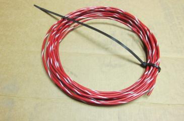
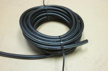
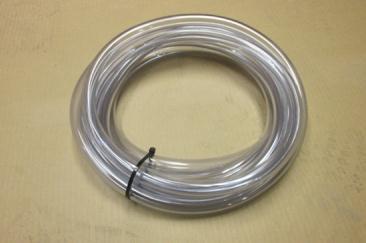
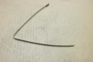
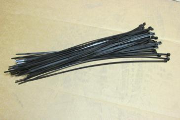
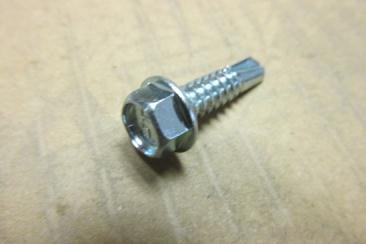
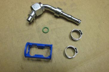
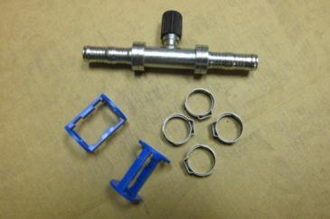
3 PREPARATION NOTES THE FOLLOWING ARE SUPPLIED IN YOUR KIT FOR GENERAL USE THROUGHOUT THE INSTALLATION: Vinyl Clad linestakes. These are used to attach hoses and wiring harnesses to the vehicle or other structure. There are various types and sizes including 1, 2, 3, 2 double and 2 twisted. These are secured with self-tapping screws to the vehicle or other structure. These screws will require a screwgun/power screwdriver for installation. Tie Wraps (also called cable ties, cable wraps, wire ties, zip ties). These are used to secure bundles of hoses or wiring harnesses together. They are NOT used to secure hoses and wiring to the vehicle. These are 14 plastic. There are also 3 stainless steel 14 tie wraps supplied for securing the fire protective sleeve to the refrigerant hoses between the compressor and the service ports. Hose Clamps (wormgear clamps) used on hoses, #10 and 7/8 Wire Loom (Convoluted Tube). This comes in 1/4, 1/2, 3/4, and 1 sizes and is used to protect wiring and hoses at various points in the vehicle. It is easily cut to length. Trim Lock. Used to trim metal openings and edges. Various specialty hardware including grommets, plates, spacers and shims. Various general hardware including screws, bolts, washers, lock washers and nuts. Self-Tapping 14 x 1 screws ( ) are used frequently. Plumbing fittings including nipples, wyes, ells, splices, manifolds and O rings. Electrical wiring of various sizes and lengths including wiring harnesses. Hoses 5/8 heater, 7/8 drain and #6, #8 and #10 refrigerant. LLC Rev A 06/13 Page 3 of


4 IN ADDITION TO AN ASSORTMENT OF GENERAL TOOLS AND SUPPLIES, THE CUSTOMER WILL NEED THE FOLLOWING: Silicone Seal (as applied by a caulk gun) for sealing access holes and providing some protection for hoses in various places. Mineral Oil for use on the O rings associated with each refrigerant hose fitting and the drier connections. Refrigerant Fittings Crimp Tool. If you do not have this tool, take a fitting from your kit with you to your local auto supply store for help in obtaining a tool. An assortment of different size eyelet lugs (terminal rings) for wiring use. These are attached to bare wire and crimped. The lugs are then attached to screw terminals on devices and boards or attached to the vehicle chassis with self-tapping screws. An assortment of butt splices. These are used to join bare wires to make connections. They are crimped. Once crimped they should be weather proofed. If you use Perma-Seal Butt Connectors you can simply use a heat gun or torch to shrink the cover around the connection to seal it. If you use standard butt connectors, you will need to slip a piece of shrink tubing over one wire, do your crimp, slide the shrink tubing over the connection and heat/seal with a torch or heat gun. LLC Rev A 06/13 Page 4 of


5 Please read the following notes before beginning installation: Parts Numbers for parts will be noted the first time the parts are referred to in the instructions only. Plumbing and electrical wiring often run in parallel so installation involves some switching back and forth between plumbing and electrical. Diagrams are provided at the end of these instructions, illustrating the air conditioning path, the heating path and the wiring runs for the installation. You may follow them as you read these instructions. Pictures of all the parts noted on the Parts List are included at the end of the instructions. Using the zoom tool (+ symbol) allows you to magnify pictures (assuming you are viewing this document on a computer and not as a printout). This may provide some additional clarification on some pictures. Also, if you print these instructions, note that several items are in color so a color copy is best. When installing refrigerant lines, if you install one end but do not immediately install the other end, cover that end with a cap or tape (electrical) to keep out contaminates. As you unpack your kit, locate the install label ( ) and record your kit number on it. Also as you unpack your Condenser and Evaporator you need to note the serial numbers for these units on the label as well. (Note: You will need these numbers if you ever have to call ProAir for service). Cut a 40 length of #8 hose ( ) and #10 hose ( ) from the bulk hose and set aside for later use. Heater Hose (Assembly # ) is shipped as one piece and should be cut in half before installation begins. Don t confuse this with the same hose under assembly which is used in another part of the installation. Remove the air cleaner before beginning installation. Reinstall after system installation. GENERAL RULE: AVOID CONTACT AS MUCH AS POSSIBLE WITH OEM EQUIPMENT AS YOU PROCEED WITH THE INSTALL (KEEP ITEMS YOU INSTALL AWAY FROM ORIGINAL EQUIPMENT COMPONENTS). LLC Rev A 06/13 Page 5 of
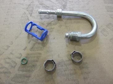
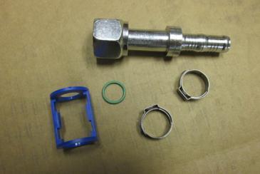
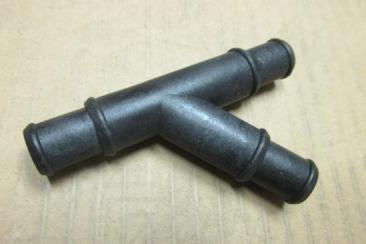
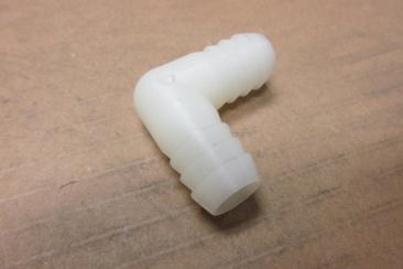
6 PARTS LIST Item # Part # Qty Description Harness, 15 Amp Power Relay Harness, 20 Amp Power Relay Wire, 12 Gauge Blue, w/white Stripe, Wire, 12 Gauge Red, w/white Stripe, Breaker, 40 Amp Circuit Harness, 7.5 Amp Power Relay Wire, 12 Gauge Red, Harness, Wire Condenser Harness, Sprinter Evaporator Wire, 6 Gauge Red, 28 (Maximum 60) Harness, 25 Mini Thermostat Module, Controller 7 Speed Thermostat, Digital Mini Breaker, 80 Amp Circuit Waterproof Linestake, Clamp, Drain Hose 7/ Trim Lock, Screw, 6 x 1/2 Ph Phillips Black Tie Wrap (Wire Tie, Cable Tie), 14 x 3/ Screw, 14 x 1 Hex Washer Tek Zinc Linestake, 2 Twisted Ends Linestake, 3 Vinyl Clad Cable Tie, 14 Stainless Clamp, #10 Heater Hose (Wormgear) Tube, 3/4" Convoluted (Wire Loom) Tube, 1 Convoluted, 20 (Wire Loom) Hose, 5/8, 80, Assembly , (divided in half by customer) Hose 5/8, 25, Assembly Hose, Drain, 5/8 Clear Hose, 5/16 Refrigerant #4890 Redu B (#6) Hose, 13/32 Refrigerant #4890 Redu, 25 (#8) Hose, 1/2 Refrigerant #4890 Rebu Ba, 50 (#10) Tube, 1/4 Convoluted (Wire Loom) Tube, 1/2 Convoluted, 25 (Wire Loom) Wye, 5/8 OD cl r Ell, 90 5/8 Drain Splice, 5/8 Heater Hose Straight Splice, #8 FOR x 8 CF Straight Splice, #10 FOR x 10 CF LLC Rev A 06/13 Page 6 of
7 Ell, 90 #6 FOR x 6 CF Ell, 90 #8 FOR x 8 CF Splice (Service Port), #8 CF x 8 CF w/16mm SV Splice (Service Port), #10 CF x 10 CF w/13mm SV Ell, 90 #8 FOR x 6 CF Ell, 180 #6 MOR x 6 CF Ell, 180 #10 MOR x 10 CF Valve, Kazoo, 3/4" ID x Bracket, Cap Mounting 110/12v Tape, Prestite, Refrigerant, Sleeve, Fire Protective, 2 I.D Label, Refrigerant Capacity, Blank Label, Anti-Freeze Mix Label, Door Jamb Card, Information, Warranty Registration Label, Circuit Legend Label, Warning Temperature Probe Label, Warning Thermostat Load LLC Rev A 06/13 Page 7 of
 by stretching out the following wires: Large Red (6")
 (01 000 319)(Goes to Ignition) Blue/White Stripe (12 gauge) (01 000 318)(Goes to Booster Pump/Water Valve) 2.")
(04 000 078). Wrap the point where the wires enter the wire loom with electrical tape to secure the wires (Figure 2).")

 refrigerant hoses, the Customer Created Harness and the Condenser Harness (01 000 352)(Figure 4).")
. Figure 4 4.")
8 INSTRUCTIONS 1. Prepare a Wire Harness to run to the Control Panel (to be created later) by stretching out the following wires: Large Red (6 gauge) ( )(Goes to 80 Amp Breaker/Battery) Small Red (12 gauge) ( )(Goes to Compressor) Red/White Stripe (12 gauge) ( )(Goes to Ignition) Blue/White Stripe (12 gauge) ( )(Goes to Booster Pump/Water Valve) 2. Tape the ends together as in Figure 1 and go in about two feet and start inserting the wire bundle in 1/2 wire loom (convoluted tube)( ). Wrap the point where the wires enter the wire loom with electrical tape to secure the wires (Figure 2). Install the entire wire loom. The small red wire will have an excess length that will be used later (Figure 3). This harness will be referred to in these instructions as the Customer Created Harness. Figure 1 Figure 2 Figure 3 3. Stretch out the two 5/8 heater hoses ( )(created by the customer as noted in the Preparation Notes), the #6 ( ) and #10 ( ) refrigerant hoses, the Customer Created Harness and the Condenser Harness ( )(Figure 4). Mark one of the heater hoses with red electrical tape (or in some other way) at intervals to designate it as the Evaporator In hose (Figure 4 Inset). Figure 4 4. Route the bundle under the vehicle through the 3 access hole in the inner wall of the vehicle body on the driver rear side (Figure 5). Then bring the bundle up the 5 x 1 1/4" hole you created during the Evaporator install into the vehicle (Figure 6). Figure 5 Figure 6 LLC Rev A 06/13 Page 8 of
 port of the Evaporator (Figure 7).")
(Figure 8).")

 and the other hose to the top port, Evaporator")
9 5. Pull enough length of the refrigerant hoses to reach the Evaporator Refrigerant ports (on left side). Install Fitting on the #10 hose and attach on the bottom (suction) port of the Evaporator (Figure 7). Install Fitting on the #6 hose and attach on the top (liquid) port. After securing the fittings, wrap them with Prestite tape ( )(Figure 8). Note: Apply mineral oil to the green O ring on each refrigerant fitting throughout the installation. Figure 7 Figure 8 Liquid Port Suction Port Prestite Tape 6. As with the refrigerant hoses, pull enough of the heater hose lines to reach the Evaporator Heating ports (on the right side) and attach the hose with red tape to the bottom port, Evaporator In (coolant from engine) and the other hose to the top port, Evaporator Out (coolant to engine). Secure these lines to the Evaporator with clamps ( )(Figure 10). Note: The Evaporator is shipped with nitrogen in the heater lines that will escape when the shipping plugs are removed. Figure 9 Figure 10 LLC Rev A 06/13 Page 9 of

 and the eyelet lug on the pigtail (Black wire)(figure 11).")
 in any order (Figure 11 Inset).")
 with 2 linestakes (02 000 015) evenly")
10 7. Prepare the Evaporator Harness ( ) connection to the Evaporator Pigtail as follows: Evaporator Harness Both Red wires are not used Both Yellow wires are not used Either Orange wire is used Blue goes to either connection on the Thermostat Blue goes to either connection on the Thermostat Evaporator Pigtail Black wire is grounded to the chassis Red wire is not used Yellow wire is not used Orange wire Ground to Chassis Thermostat Harness Group Harness Group Figure 11 Evaporator Harness Evaporator Pigtail Cut off the connectors on the harness and the pigtail. Leave the spade connectors on the harness (Blue wires) and the eyelet lug on the pigtail (Black wire)(figure 11). Strip wires and butt splice one of the Orange wires (either one) on the harness to the Orange wire on the pigtail. Connect the blue wires on the harness to the Freeze Thermostat (on the Evaporator) in any order (Figure 11 Inset). Ground the Black wire on the pigtail to the vehicle chassis using a self-tapping screw ( ). Wrap the bundle with electrical tape. 8. Take the Evaporator Harness and four hose lines and attach them to the lip of the Evaporator (where the Evaporator Pigtail is already attached) with 2 linestakes ( ) evenly spaced (Figure 12) using selftapping screws. Then run the bundle down the wall and attach using 2 linestakes (Figure 13). Go back and tie wrap ( ) the bundle between the linestakes. Linestakes Figure 12 Figure 13 Wire Ties LLC Rev A 06/13 Page 10 of
 and secure with a clamp (02 000 021)(Figure 14).")
.")

 and out the hole you")

11 9. Prepare the drain hoses by taking the bulk drain hose ( ) and cutting off two 2 1/2 pieces and then cutting the remainder in half. Insert each 2 1/2 piece into one of the ells ( ) and secure with a clamp ( )(Figure 14). Take the two longer length hoses and attach them to the ells with clamps. Take the remaining end of the 2 1/2 pieces and insert them into the drain ports on each side of the Evaporator and secure with clamps (Figure 15). Figure 14 Figure Route the passenger side drain hose to the side and down into the exit hole you created during the Evaporator mounting. The hose will go between the inner and outer side walls and will exit the 3 access hole on the inner side wall under the vehicle. Leave about 6 exposed under the vehicle (cut off any excess) and attach a kazoo valve ( ) and secure with a tie wrap. On the driver side route the hose to the side and parallel with the wiring/heater hose/refrigerant hose run (Figure 16) and out the hole you previously created. Secure the hose to the other hoses with tie wraps. As on the passenger side, this hose will go between the inner and outer side walls and will exit the 3 access hole on the inner side wall under the vehicle. Leave about 6 exposed under the vehicle (cut off any excess) and attach a kazoo valve and secure with a tie wrap (Figure 17). Tie Wrap Under Vehicle Kazoo Valve Drain Hose Figure 16 Figure 17 LLC Rev A 06/13 Page 11 of


12 11. Leave the Evaporator Harness inside the vehicle at the entrance to the hole. Leave about three feet of the Condenser Harness and the Customer Created Harness inside the vehicle and pull the slack underneath. Route the bundle (four hoses, Compressor Harness, and the Customer Created Harness) around the wheel well area (Figures 18 and 19) and then back to the driver side to the area where you mounted the Booster Pump, Condenser Relay, Drier and Water Valve. Secure with 2 linestakes to the vehicle and tie wrap the bundle between linestakes. Figure 18 Figure 19 Condenser 12. The heater hose marked with red tape is cut, attached and clamped to the output of the Water Valve. The other end is attached to the input of the Booster Pump and routed to the engine compartment (Figure 20). The second heater hose runs from the Evaporator Out to the engine compartment. A third heater hose ( , Assembly ) should be marked with orange tape (or in some other way) and is clamped to the Wye between the Booster Pump and the Water Valve and runs to the engine compartment (Figure 21). From Engine Compartment To Booster Pump In To Engine Compartment Water Valve Out To Evaporator Wye Booster Pump Figure 20 Figure 21 LLC Rev A 06/13 Page 12 of
.")
 with Fitting")
 with Fitting 05 000 504 is attached to the Condenser In (top port) and runs to")
.")
13 13. COOLING The #6 hose (Evaporator In) is cut and Fitting is installed and the hose is connected to the Drier Output (Figure 22). A short piece of #6 hose is cut (length based on your space requirements). It connects the Drier Input with Fitting to the Condenser Output (bottom port) with Fitting (Figure 23). The #8 hose ( ) with Fitting is attached to the Condenser In (top port) and runs to the engine compartment (Figure 24). The Condenser Harness breaks away from the bundle here and will be connected later (Figure 25). The Blue/White Stripe wire breaks away from the Customer Created Harness here and will be connected later (Figure 25). Drier Out Figure 22 Figure 23 Condenser In (Top Port) Condenser Harness To Compressor Figure 24 Figure 25 LLC Rev A 06/13 Page 13 of
 where the Small Red Wire exits the Customer Created Harness (Figure 26) and is inserted in a")
 and Red/White Stripe wire")
 under the seat. To Compressor Customer Created Harness Figure 26 Figure 27 15.")
 (Figures 28 & 29).")
14 14. The five hoses and the Customer Created Harness now run to the area under the driver s seat (pedestal) where the Small Red Wire exits the Customer Created Harness (Figure 26) and is inserted in a 1/4 piece of wire loom ( ) and is routed under the vehicle to the Compressor. The Customer Created Harness with the Large Red wire (80 Amp Relay) and Red/White Stripe wire (Ignition) enters a hole in the floor of the vehicle (Figure 27) which terminates in the Wire Compartment (OEM) under the seat. To Compressor Customer Created Harness Figure 26 Figure The five hoses are routed to the front of the vehicle and secured in place with 2 linestakes attached to the vehicle and tie wraps (keeping them in a bundle) (Figures 28 & 29). 2 Twisted Linestake Figure 28 Figure 29 LLC Rev A 06/13 Page 14 of
(Figure 30).")


 These five hoses with wire loom will need to be individually cut to the proper length as you route them to")
15 16. The five hoses route through a hole in a cross member of the frame which should be trimmed with Trim Lock ( )(Figure 30). Wire loom should be used, 1 ( ) on the heater hoses and 3/4" ( ) on the refrigerant hoses, as they enter this hole and should continue all the way to their destinations in the engine compartment (Figures 30 & 31). (Note: As it is difficult to route all five hoses through the hole with wire loom on them, the heater hoses will have a one foot piece inserted before the hole and then a longer piece after they exit the hole.) These five hoses with wire loom will need to be individually cut to the proper length as you route them to their destinations. Figure 30 Figure 31 Trim Lock Wire loom around hoses 17. The hoses are secured to the vehicle with 2 linestakes in the engine compartment (Figures 32 & 33). Figure 32 Figure 33 LLC Rev A 06/13 Page 15 of

 beginning about 6 above the ends that")
.")

16 ENGINE COMPARTMENT COOLING 18. Take the 40 pieces of #8 and #10 hose you cut earlier and connect Fitting to the #8 hose and Fitting to the #10 hose. These hoses are wrapped in a fire protective sleeve ( ) beginning about 6 above the ends that connect to the Compressor (Figure 34). The sleeve is secured to the hoses with three aluminum tie wraps ( ). The bundle is now fed from above the engine to just above the compressor (Figure 35). Fire Proof Sleeve Aluminum Ties 6 Figure 34 Figure The #10 hose is connected to the Suction side (driver side) of the compressor and the #8 hose to the Discharge side (passenger side)(figure 36). The hoses are secured to the vehicle frame with a 2 linestake at an appropriate point (Figure 37). Figure 37 Compressor Ports Linestake LLC Rev A 06/13 Page 16 of
 into a U and install it near the oil filler on the engine (Figure ).")


17 Figure Bend a 3 linestake ( ) into a U and install it near the oil filler on the engine (Figure ). After all the hoses have been connected the bundle will be secured to this linestake by using a second linestake. 3 Linestake Figure 21. In the engine compartment, connect the #10 hose to the service (charge) port splice and the #8 hose to the service port splice. Crimp these hoses. Connect the #8 hose (from the Condenser) and the #10 hose (from the Evaporator) to their respective service port splice, crimp the connectors, and cover with wire loom (Figures 39 & 40). Figure 40 HEATING Figure 39 LLC Rev A 06/13 Page 17 of
 with two long nose vise grips (or other tools) about 6 apart to stop fluid flow")
, securing the hoses to the Wye with clamps.")

 and clamps, connect the engine side of the hose to the heater hose running to the Booster Pump In (marked with")
18 HEATING 22. Clamp the heater hose on the Heater Core Out (hose on left) with two long nose vise grips (or other tools) about 6 apart to stop fluid flow (Figure 41). You will cut the hose midway between the vise grips so make sure this is where you want to make your spice. Insert a Wye ( ), securing the hoses to the Wye with clamps. The remaining port on the Wye is connected to the hose coming from the Evaporator (unmarked hose) (Figure 42). Remove the vise grips. Figure 41 Heater Core Out Vise Grips Radiator In Wye Cut Evaporator Out Figure Clamp the hose on the Heater Core In with two vise grips (as done on the Heater Core Out) to stop fluid flow and cut the hose. Using a splice ( ) and clamps, connect the engine side of the hose to the heater hose running to the Booster Pump In (marked with Red tape)(figure 43). The hose connected to the Heater Core In is spliced to the hose (marked with Orange tape)(figure 44) which runs to the Wye between the Booster Pump and Water Valve. Remove the vise grips. Engine Out Splice Figure 44 To Wye between Pump and Water Valve Splice LLC Rev A 06/13 Page 18 of
 is run through a linestake")
.")
19 Booster Pump In Figure 43 Heater Core In 24. The hose bundle (5 hoses) is run through a linestake that is screwed to the linestake installed previously (Figures 45 & 46). Figure 45 Figure 46 Spacer LLC Rev A 06/13 Page 19 of
20 Oil Drain LLC Rev A 06/13 Page 20 of

 in the Wire Compartment (OEM) in the pedestal on the driver side (seat and cover over the compartment")
 of the compartment with the same screws (Figure 49 & Inset).")
(figures 49 & 50).")
 to the battery (located under a cover in the floor of the vehicle to the engine side of the Wire Compartment) where the")
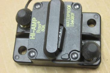
21 ELECTRICAL WIRING 25. Starting at the front of the vehicle you will install all wiring. First connect the Compressor. You previously routed a Small Red wire inside a 1/4 wire loom. Cut this wire/loom to the appropriate length. Cut the connector off the Compressor wire (Figure 47). Butt splice these wires together (Figure 48). Figure 48 Cut off Figure 47 Splice 26. Install the 80 Amp Breaker ( ) in the Wire Compartment (OEM) in the pedestal on the driver side (seat and cover over the compartment are removed). The breaker mounts to the metal bracket ( ) with self-tapping screws ( ) as shown in Figure 50. The bracket then mounts to the right side (toward rear of vehicle) of the compartment with the same screws (Figure 49 & Inset). The 6 gauge wire (red but inside a wire loom) from under the vehicle enters this compartment and mounts to the top (AUX) terminal of the Breaker (trim wire to proper length and attach an eyelet lug)(figures 49 & 50). The remaining length of wire has an eyelet lug attached and is secured to the bottom (BAT) terminal of the breaker and routes out of the Wire Compartment (Figure 51) to the battery (located under a cover in the floor of the vehicle to the engine side of the Wire Compartment) where the wire is cut to length, an eyelet lug installed and then connected to the positive terminal (Figure 52). To Battery Figure 49 To Control Panel Figure 50 LLC Rev A 06/13 Page 21 of
 Figure 51 Figure 52 BATTERY 27.")


22 To Battery From 80 Amp BAT (Breaker) From 80 Amp BAT (Breaker) Figure 51 Figure 52 BATTERY 27. The Red/White Stripe wire (Ignition) coming up from the underside of the vehicle has an eyelet lug attached and is connected to the terminal shown in Figure 53. Ignition Wire From Control Panel 80 Amp Breaker Figure 53 LLC Rev A 06/13 Page 22 of

. The two Red wires are factory butt spliced. Remove the butt splice leaving one Red wire (Figure 54, B).")
. A B Remove Figure 54 Figure 55 29. You are now ready to begin wiring.")
23 28. Connect the devices under the vehicle (Booster Pump, Condenser, Condenser Relay, Pressure Switch and Water Valve). These will interconnect with each other as well as the Condenser Harness and the Customer Created Harness coming from the rear of the vehicle (where the Control Panel you are yet to build will be located). Begin by preparing the Condenser Relay. The Pressure Switch socket is connected to the Blue wire. Do not do anything with this wire at this time. Remove the two plugs (Figure 54, A). The two Red wires are factory butt spliced. Remove the butt splice leaving one Red wire (Figure 54, B). The two Black wires are factory butt spliced with a third Black wire which has an eyelet lug on the end which will be grounded to the vehicle chassis. One of the remaining two Black wires can be removed (Figure 55). A B Remove Figure 54 Figure You are now ready to begin wiring. Wire the Condenser as follows (Figure 56): Butt splice the Red wire (Condenser Relay) to the Red Wire (Condenser Pigtail). Butt splice the Black wire (Condenser Relay) to the Black wire (Condenser Pigtail). Figure 56 LLC Rev A 06/13 Page 23 of
.")
 to the Black Wire (Condenser Harness).")
: Butt splice the Red wire/booster Pump to the Blue Wire/Water Valve and the Blue/White Stripe wire/customer")
24 30. Wire the Condenser Harness as follows (Figure 57): Butt splice the Blue Wire (Condenser Relay) that has the factory butt splice. One end goes to the Pressure Switch. Butt splice the other end to the Red Wire (Condenser Harness). Butt Splice the other Blue wire (Pressure Switch) to the Blue Wire (Condenser Harness). Butt Spice the Red/White Stripe wire (Condenser Relay) to the Black Wire (Condenser Harness). Pressure Switch Figure 57 Condenser Relay Condenser Harness 31. Booster Pump/Water Valve Wiring (Figure 58): Butt splice the Red wire/booster Pump to the Blue Wire/Water Valve and the Blue/White Stripe wire/customer Created Harness. Ground the Black wire/booster Pump to the vehicle chassis. Ground the Brown Wire/Water Valve to the vehicle chassis. 32. Ground the remaining Black wire (Condenser Relay, eyelet lug) to the vehicle chassis (Figure 59). Figure 58 Ground Grounds Figure 59 LLC Rev A 06/13 Page 24 of

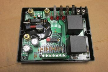
25 33. The final process of installation is to create the Control Panel. Typically, this is a piece of plywood, sometimes covered for aesthetics, and mounted somewhere out of the way in the vehicle but accessible. The following devices must be mounted on the panel: Module, Amp Breaker, Amp Fuse prewired to 40 Amp Ignition Relay, , controls Module 15 Amp Fuse prewired to 40 Amp Booster Pump/Water Valve Relay, Amp Fuse prewired to 40 Amp Clutch (Compressor) Relay, Figure 60 is a possible layout while Figure 61 shows the actual component layout in this configuration: Figure 60 Module 40 Amp Breaker Fuse/Relay Ignition Fuse/Relay Clutch (Compressor) Fuse/Relay Booster Pump/ Water Valve Figure 61 LLC Rev A 06/13 Page 25 of
26 34. The various devices in the system (Compressor, Condenser, Evaporator, Water Valve and Booster Pump) are powered by the 12 volt vehicle electrical system and are controlled by a module that talks to the devices. Board commands and power for the devices pass through relays connected to the devices. Once the Control Panel is constructed, it can be wired by either following Diagrams 3 and 4 at the end of these instructions or by using the wiring list provided in Figure 62. Connections are generally made with butt connectors or terminal ends. Diagram 5 illustrates the relays wiring schemes. The wiring for the panel comes from wiring already attached to the components on the board and from the Evaporator Harness, Condenser Harness and the Customer Created Harness. Tensioner LLC Rev A 06/13 Page 26 of
27 CONTROL PANEL WIRING Figure 62 Item # A Connection B 1 Customer Created Harness/Blue-White Stripe Butt Splice Booster Pump Relay Power Out/Red 2 Customer Created Harness/Red-White Stripe Butt Splice Ignition Relay Signal In/Orange 3 Customer Created Harness/Red-12 Gauge Butt Splice Clutch Relay Power Out/Red 4 Customer Created Harness/Red-6 Gauge Terminal 40 Amp Breaker-BAT 5 Condenser Harness/Black Terminal 40 Amp Breaker-AUX 6 Condenser Harness/Blue Butt Splice Clutch Relay Signal In/Orange 7 Condenser Harness/Red Butt Splice Evaporator Harness/Blue (either one) 8 Module-Cool Terminal Evaporator Harness/Blue (either one) 9 Module-Heat Terminal Booster Pump Relay Signal In/Orange 10 Module-+12VDC Terminal Ignition Relay Power Out/Red 11 Module-Output Terminal Evaporator Harness/Orange 12 Ignition Relay-20 Amp Fuse-Power In/Red Terminal 40 Amp Breaker-BAT 13 Clutch Relay-7.5 Amp Fuse-Power In/Red Terminal 40 Amp Breaker-AUX 14 Booster Pump Relay-15 Amp Fuse-Power In/Red Terminal 40 Amp Breaker-BAT 15 Ignition Relay Ground/Black Eyelet Lug Vehicle Chassis 16 Clutch Relay Ground/Black Eyelet Lug Vehicle Chassis 17 Booster Pump Relay Ground/Black Eyelet Lug Vehicle Chassis 18 Module Ground Eyelet Lug Vehicle Chassis LLC Rev A 06/13 Page 27 of


 can be connected to the Thermostat Harness.")
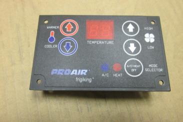
28 35. The Control Panel is finished by wiring the Thermostat. The Thermostat is connected to the Thermostat Harness by a 7- pin connector on one end of the harness (Figure 63). The other end of that harness is hard wired into the Module (Figure 64). Figure 63 Figure 64 Module #2 Jumpers THERMOSTAT CONNECTION Thermostat wires connect to terminal block on the Module as follows: Thermostat Wire Red/White Black Blue Pink Yellow Red Orange Module Terminal 12VDC Ground Cool Heat A B C 36. The Thermostat ( ) can be connected to the Thermostat Harness. Four screws ( ) are supplied for mounting the unit to the location you select (Figure 65). Figure 65 LLC Rev A 06/13 Page 28 of
.")

29 37. With the installation now complete, seal all holes with silicone seal. This includes holes created for hoses/wiring harnesses to enter and exit the vehicle (Figure 66). This is to keep out moisture and contaminates (Figure 66). Also apply silicone behind the water valve and any locations where hoses come in contact with any vehicle structures (Figure 67), especially OEM related components. Seal Figure 66 Seal Figure 67. The cooling system should now be evacuated. PAG Oil and R134a refrigerant are then added according to the chart below based on the Evaporator and Condenser you have in your system: Evaporator Condenser Refrigerant (oz) PAG Oil (oz) EZ Several informational labels are provided to document installation and provide those who service the system with proper maintenance information. Those are: This label notes the refrigerant This label notes the anti-freeze This label provides information and PAG oil capacity of your mixture ratio and should also be as to date of installation and the system. It should be applied applied in the engine installer s name. The serial somewhere in the engine compartment. numbers for the Condenser and compartment. Evaporator are noted here as well as your kit number. It should be attached to the driver LLC Rev A 06/13 side door jamb. Page 29 of


30 PARTS LLC Rev A 06/13 Page 30 of


31 LLC Rev A 06/13 Page 31 of


32 LLC Rev A 06/13 Page 32 of


33 LLC Rev A 06/13 Page 33 of
34 Diagram 1 AIR CONDITIONING LAYOUT 560 EVAPORATOR In EVAPORATOR Out Fitting Fitting Fitting Out In DRIER Fitting Fitting Fitting Out CONDENSER In Drain Hoses Suction COMPRESSOR Discharge Manifold Fitting Manifold Fitting PORT PORT Notes: Part Numbers for fittings for hoses connecting to devices are noted #6 Hose=5/16 =PN , #8 Hose=13/32 =PN , #10 Hose=1/2 =PN Fittings require a special crimp tool LLC Rev A 06/13 Page 34 of
35 Diagram 2 HEATING LAYOUT 560 EVAPORATOR In B PUMP Out Wye In WATER VALVE Out In From Engine Splice Splice IN Heater Hose 5/8 Ell EVAPORATOR HEATER CORE To Radiator Wye OUT Out Notes: Dotted lines above represent OEM installed hose Kit installed hose is 5/8 standard heater hose PN attached with clamps LLC Rev A 06/13 Page 35 of
36 - BATTERY + BAT 80 AMP BREAKER AUX WIRING DIAGRAM / 560 EVAPORTOR WITH DIGITAL CONTROL Diagram 3 40 AMP BREAKER BAT 15 AMP FUSE Ignition IGNITION RELAY Signal In Power Out Power In Ground MODULE Out 12 VDC In Heat Cool Ground EVAPORATOR In Ground PUMP/VALVE RELAY Signal In Power Out PUMP Power In Ground Thermostat wires connect to the terminals on the Board as follows: Thermostat Wire Red/White Black Blue Pink Yellow Red Orange Board Terminal 12VDC Ground Cool Heat A B C 15 AMP FUSE Power In Ground WATER VALVE Power In Ground FREEZE THERMOSTAT CONDENSER RELAY Signal In CONDENSER Power Out Power In Power In Ground Ground PRESSURE SWITCH CLUTCH RELAY AUX 15 AMP FUSE Signal In Power Out Power In Ground CLUTCH (Compressor) NOTES: Wire crosspoints do not represent connections. Wires that T are butt spliced. Ground Wires can be individually grounded to the vehicle chassis or can be daisy-chained together in any fashion and then grounded. LLC Rev A 06/13 Page 36 of
37 Diagram 4 HARNESS DIAGRAM SPRINTER 170 WITH 560 EVAPORATOR/DIGITAL CONTROL Blue Brown Water Valve Blue/White Stripe Vehicle Ground Neg Wire Loom (Customer Created Harness) Large Red Black Red Booster Pump Amp Breaker Red Battery Pos Red/White Stripe Ignition Control Red Clutch (Compressor) Board Condenser Harness (Black Insulated Wire) Blue Blue Blue Pressure Switch Condenser /036 Red Black Red Black Blue Red/White Red Black Black Condenser Relay Vehicle Ground Evaporator Harness Orange Vehicle Ground Black Orange Evaporator Blue Blue Blue Blue Freeze Thermostat LEGEND = Butte Splice LLC Rev A 06/13 Page 37 of


38 Diagram 5 RELAY WIRING Relays , Power Relay Relay with tab side down looking on end: 1 Power Out / Red 2 Ground / Black 3 Signal In / Orange 4 Power In / Red Relay / Condenser Relay Relay with tab side down looking on end: 1 Power In / Red-White 2 Signal In / Blue 3 Ground / Black 4 Power Out / Red LLC Rev A 06/13 Page of
INSTALLATION INSTRUCTIONS FOR AIRTECH II / TIE-IN. For Nissan NV
 INSTALLATION INSTRUCTIONS FOR AIRTECH II / TIE-IN For Nissan NV Corporate Headquarters ProAir, LLC 28731 County Road 6; Elkhart, IN 46514 Phone: (574) 264-5494; Toll Free: 800-338-8544; Fax: (574) 264-2194
Warning Do not attempt to install A/C units unless you are experienced with servicing A/C systems!
 TOOLS REQUIRED: INSTALLATION INSTRUCTIONS PT-A-406 Rear HVAC System for 2014-2018 RAM PROMASTER without OEM rear AC/Heat Prep Package Fittings ***This system can also be used for a Promaster van with the
PRODUCT: Install Instructions, MV-1 C/O Std, With Aux Fan RELEASE DATE: 2/28/14 REVISION DATE: 9/30/2014 PART NUMBER: Rev C
 Parts List (1) 01 000 027 Switch, 4 Position Blower (1) 04 000 007 Hose, 1/2 ID Drain, 6 (1) 01 000 087 Harn, Resistor (1) 04 000 078 Tube, Convo 1/2 x 24 (2) 01 000 136 Relay, 40 Amp (1) 04 000 015 Hose,
Installation Instructions for Lingenfelter GM 2500 Suburban & Yukon XL Auxiliary Fan System (with AC clutch controlled fan output)
") Installation Instructions for Lingenfelter 2007-2013 GM 2500 Suburban & Yukon XL Auxiliary Fan System (with AC clutch controlled fan output) PN L300080607 Revision - 1.1 Lingenfelter Performance Engineering
Installation Instructions for Lingenfelter 2007-2013 GM 2500 Suburban & Yukon XL Auxiliary Fan System (with AC clutch controlled fan output) PN L300080607 Revision - 1.1 Lingenfelter Performance Engineering
INSTALLATION INSTRUCTIONS FOR COZY CAB A-1 AIR CONDITIONING KIT
 INSTALLATION INSTRUCTIONS FOR COZY CAB A-1 AIR CONDITIONING KIT 05-11 INSTALLATION INSTRUCTIONS A-12235 Air Conditioner Kit Cab set up instructions; This air conditioning kit is designed to be used with
INSTALLATION INSTRUCTIONS FOR THE TOMAHAWK ELECTRIC REVERSE
 INSTALLATION INSTRUCTIONS FOR THE TOMAHAWK ELECTRIC REVERSE LAST UPDATED: April 2018 Thank you for choosing the Motor Trike Electric Reverse. We ask that you read the directions before you start and follow
jegs.com
 Contents Wiring Harness w/ Fuse Panel Installation Instructions Turn Signal Plug w/ Terminals 2 Headlight Plugs 3/4 Grommet 10 ¼ Terminals 4 Ring Terminals 10 Wire Ties Fusible Link 2 Screws & Nuts 2 Plastic
Installation Tips for your Crimestopper/ProStart Remote Start system (add-on for GM vehicles) v1.02 updated 1/16/2013
 v1.02 updated 1/16/2013") Installation Tips for your Crimestopper/ProStart Remote Start system (add-on for GM vehicles) v1.02 updated 1/16/2013 Thank you for purchasing your remote start from MyPushcart.com - an industry leader
Installation Tips for your Crimestopper/ProStart Remote Start system (add-on for GM vehicles) v1.02 updated 1/16/2013 Thank you for purchasing your remote start from MyPushcart.com - an industry leader
Air Conditioner for M915 A0/A1 Truck
 RD-2-4530-0 Air Conditioner for M915 A0/A1 Truck INSTALLATION INSTRUCTIONS Install refrigerant compressor per instructions provided with compressor mount kit. CAUTION: Edges of sheet metal can be sharp!
PERFECT FIT SERIES IN-DASH HEAT/ COOL/ DEFROST 1969 CHEVROLET CAMARO/ FIREBIRD NOTE: INSTRUCTIONS DEPICT CAMARO
 specializing in AIR CONDITIONING, PARTS AND SYSTEMS for your classic vehicle PERFECT FIT SERIES IN-DASH HEAT/ COOL/ DEFROST 1969 CHEVROLET CAMARO/ FIREBIRD NOTE: INSTRUCTIONS DEPICT CAMARO CONTROL & OPERATING
Installation Tips for your Excalibur Remote Start (for Honda and Acura Vehicles) rev 11/28/2012
 rev 11/28/2012") Installation Tips for your Excalibur Remote Start (for Honda and Acura Vehicles) rev 11/28/2012 Thank you for purchasing your remote start from MyPushcart.com - an industry leader in providing remote starts
Installation Tips for your Excalibur Remote Start (for Honda and Acura Vehicles) rev 11/28/2012 Thank you for purchasing your remote start from MyPushcart.com - an industry leader in providing remote starts
Installation Tips Crimestopper/ProStart Remote Start system + PLJX + DLRM + SPDT (for GM vehicles) T0760 v1.1 updated 2/5/14
 T0760 v1.1 updated 2/5/14") Installation Tips Crimestopper/ProStart Remote Start system + PLJX + DLRM + SPDT (for GM vehicles) T0760 v1.1 updated 2/5/14 Thank you for purchasing your remote start from MyPushcart.com - an industry
Installation Tips Crimestopper/ProStart Remote Start system + PLJX + DLRM + SPDT (for GM vehicles) T0760 v1.1 updated 2/5/14 Thank you for purchasing your remote start from MyPushcart.com - an industry
INSTALLATION & OWNER S MANUAL
 1 of 18 INSTALLATION & OWNER S MANUAL (*Not including cab & other accessories) A/C Alternator Kit: Yamaha Drive & Drive2 P/N: 1ACYDR2DRK Recommended it be installed with Curtis Cab: Sandstone (p/n 1GCYD1-A,
Installation Tips for your Crimestopper/ProStart Remote Start system (for GM vehicles) v1.01 updated 2/27/2012
 v1.01 updated 2/27/2012") Installation Tips for your Crimestopper/ProStart Remote Start system (for GM vehicles) v1.01 updated 2/27/2012 Thank you for purchasing your remote start from MyPushcart.com - an industry leader in providing
Installation Tips for your Crimestopper/ProStart Remote Start system (for GM vehicles) v1.01 updated 2/27/2012 Thank you for purchasing your remote start from MyPushcart.com - an industry leader in providing
INSTRUCTIONS. w w w. h d o n l i n e s h o p. d e SPRINGER AUXILIARY LAMP KIT 1WARNING -J03497 REV General.
 INSTRUCTIONS -J097 REV. 0-0-00 Kit Number 6986-0A General Auxiliary/fog lamps are not included in this kit. The lamps must be purchased separately. HDI (International) motorcycles should only use approved
& 76 CHEVROLET NOVA HEATER ONLY
 specializing in AIR CONDITIONING, PARTS AND SYSTEMS for your classic hi l PERFECT FIT IN-DASH HEAT/ COOL/ DEFROST 1969-74 & 76 CHEVROLET NOVA HEATER ONLY CONTROL & OPERATING INSTRUCTIONS The controls on
Installation Instructions
 Installation Instructions Jeep JK Unlimited (2007 Present) Mounting Bracket and Air Line System Kit for ARB On-Board Twin Air Compressor (CKMTA12) Made in the USA Kit Contents: 1 Bracket for ARB Compressor
Small Block Chevrolet Serpentine Drive System with & without Power Steering
 an ISO 9001:2008 Registered Company Small Block Chevrolet Serpentine Drive System with & without Power Steering 18865 Goll St. San Antonio, TX 78266 Phone: 210-654-7171 Fax: 210-654-3113 www.vintageair.com
2013 Road King CVO FLHRSE5 Detachable Fairing w/ Garmin Zumo 665 Installation Instructions
 2013 Road King CVO FLHRSE5 Detachable Fairing w/ Garmin Zumo 665 Installation Instructions 1 1. Turn ignition switch to on position and leave there. This will prevent alarm from going off when you disconnect
PERFECT FIT SERIES IN-DASH HEAT/ COOL/ DEFROST MUSTANG
 specializing in AIR CONDITIONING, PARTS AND SYSTEMS for your classic vehicle PERFECT FIT SERIES IN-DASH HEAT/ COOL/ DEFROST 1969-70 MUSTANG CONTROL & OPERATING INSTRUCTIONS The controls on your new Perfect
Installation Tips for your Add-on Remote Start (for GM vehicles with INTSL Install 2) v3.2 Updated 11/12/2012
 v3.2 Updated 11/12/2012") Installation Tips for your Add-on Remote Start (for GM vehicles with INTSL Install 2) v3.2 Updated 11/12/2012 Thank you for purchasing your remote start from MyPushcart.com - an industry leader in providing
Installation Tips for your Add-on Remote Start (for GM vehicles with INTSL Install 2) v3.2 Updated 11/12/2012 Thank you for purchasing your remote start from MyPushcart.com - an industry leader in providing
AUXILIARY BATTERY BOX INSTALLATION INSTRUCTIONS
 AUXILIARY BATTERY BOX INSTALLATION INSTRUCTIONS The original TOMMY GATE hydraulic lift Assembling the Auxiliary Battery Box 1. Remove the cover from the auxiliary battery box by removing the two nuts and
Small Block Ford Serpentine Drive System with & without Power Steering
 an ISO 9001:2008 Registered Company Small Block Ford Serpentine Drive System with & without Power Steering 18865 Goll St. San Antonio, TX 78266 Phone: 210-654-7171 Fax: 210-654-3113 www.vintageair.com
WirelessONE. Kit INSTALLATION GUIDE. Key Fob Activated Compressor System
 Kit 25870 Key Fob Activated Compressor System MN-751 (041202) ECR 7260 INSTALLATION GUIDE For maximum effectiveness and safety, please read these instructions completely before proceeding with installation.
80703 & Backside License Plate Mount for Jeep JK Wrangler (80707) & 10+ (80703)
 & 10+ (80703)") 80703 Backside Mount 80707 Backside Mount REQUIRED TOOLS 10mm SOCKET 13mm SOCKET 4mm HEX KEY WIRE CRIMPS WIRE STRIPPERS ELECTICAL TAPE SCREW DRIVER KIT CONTAINS BACKSIDE MOUNT LICENSE PLATE BRACKET WITH
80703 Backside Mount 80707 Backside Mount REQUIRED TOOLS 10mm SOCKET 13mm SOCKET 4mm HEX KEY WIRE CRIMPS WIRE STRIPPERS ELECTICAL TAPE SCREW DRIVER KIT CONTAINS BACKSIDE MOUNT LICENSE PLATE BRACKET WITH
Installation Tips for your Remote Start system (for RS4LX>GMBP for GM vehicles)
") Installation Tips for your Remote Start system (for RS4LX>GMBP for GM vehicles) Thank you for purchasing your remote start from MyPushcart.com - an industry leader in providing remote starts to doit-yourself
Installation Tips for your Remote Start system (for RS4LX>GMBP for GM vehicles) Thank you for purchasing your remote start from MyPushcart.com - an industry leader in providing remote starts to doit-yourself
Hush-O-Matic MRS Control Package
 Hush-O-Matic MRS Control Package 06-49192 Congratulations on your purchase! The Hush-O-Matic MRS Control package allows you to choose a few different modes including always quiet and always loud. Controlling
3 in 1 TRAIL CHARGER with LOCKOUT
 Owner s Manual P/N: 283821 500 3 in 1 TRAIL CHARGER with LOCKOUT 283821 01 Version 2.04 07/05/2011 Owners Manual Operation Installation Wiring Diagram Troubleshooting Parts Breakdown 1 GENERAL OPERATION
Backside License Plate Mount for Jeep JK Wrangler
 REQUIRED TOOLS 10mm SOCKET 13mm SOCKET 4mm HEX KEY WIRE CRIMPS WIRE STRIPPERS ELECTICAL TAPE SCREW DRIVER KIT CONTAINS BACKSIDE MOUNT LICENSE PLATE BRACKET WITH LEDS PLASTIC PASS-THROUGH GROMMET STAINLESS
Part # Mopar LX Level 1 Air Suspension System
 Part # 13040199 05-14 Mopar LX Level 1 Air Suspension System Front Components: 1 1304409 Front RQ ShockWave Kit for Stock Lower Arms Rear Components: 1 13044099 Rear CoolRide Kit 1 13040709 RQ Series Rear
Important information about your new a/c system. Please read the following directions prior to installing this a/c system.
 PAGE 1 Important information about your new a/c system. Please read the following directions prior to installing this a/c system. PN s: CK-7586258, CK-758642, CK-7586304, CK7586SBC, CK-7486NC Jeep CJ Series
Small Block Ford Serpentine Drive System with & without Power Steering
 an ISO 9001:2008 Registered Company Small Block Ford Serpentine Drive System with & without Power Steering 18865 Goll St. San Antonio, TX 78266 Phone: 210-654-7171 Fax: 210-654-3113 www.vintageair.com
Step 1 Wiring your remote start. Installation Tips for your Remote Start system (for GM vehicles) V3.3 revised 9/12/2013
 V3.3 revised 9/12/2013") Installation Tips for your Remote Start system (for GM vehicles) V3.3 revised 9/12/2013 Thank you for purchasing your remote start from MyPushcart.com - an industry leader in providing remote starts to
Installation Tips for your Remote Start system (for GM vehicles) V3.3 revised 9/12/2013 Thank you for purchasing your remote start from MyPushcart.com - an industry leader in providing remote starts to
TIP SHEET. Installation Tips for your RS OL-MDB-CH6 (1) (for Jeep vehicles) T1227 v1.0 3/19/14
 (for Jeep vehicles) T1227 v1.0 3/19/14") TIP SHEET Installation Tips for your RS-360 + OL-MDB-CH6 (1) (for Jeep vehicles) T1227 v1.0 3/19/14 Thank you for purchasing your remote start from MyPushcart.com - an industry leader in providing remote
TIP SHEET Installation Tips for your RS-360 + OL-MDB-CH6 (1) (for Jeep vehicles) T1227 v1.0 3/19/14 Thank you for purchasing your remote start from MyPushcart.com - an industry leader in providing remote
Big Block Chevrolet Serpentine Drive System with & without Power Steering
 an ISO 9001:2008 Registered Company Big Block Chevrolet Serpentine Drive System with & without Power Steering 18865 Goll St. San Antonio, TX 78266 Phone: 210-654-7171 Fax: 210-654-3113 www.vintageair.com
COLD WEATHER START KIT Platinum Mini Split
 COLD WEATHER START KIT Platinum Mini Split Cold Weather Start Kit: To be used in conjunction with Platinum Mini Split cooling system. The Coolest Thing In Wine Storage LASS.MPS 051515 Conforms to ANSI/UL
Installation Tips for your Remote Start system (for Toyota Camry & Prius C, ) Crimestopper RS0+ EVO-ALL T3468 rev#1.
 Crimestopper RS0+ EVO-ALL T3468 rev#1.") Installation Tips for your Remote Start system (for Toyota Camry & Prius C, 2012-2014) Crimestopper RS0+ EVO-ALL T3468 rev#1.1 1/22/2015 Thank you for purchasing your remote start from MyPushcart.com -
Installation Tips for your Remote Start system (for Toyota Camry & Prius C, 2012-2014) Crimestopper RS0+ EVO-ALL T3468 rev#1.1 1/22/2015 Thank you for purchasing your remote start from MyPushcart.com -
1. Disconnect the battery. This is important! This will prevent air bag deployment.
 PARTS PACKING LIST Evaporator assembly Drain tube Plastic air plug Hardware package 11040 3601 W. Clarendon Phoenix, Arizona 85019 (602) 233-0090 800-648-4475 www.ackits.com 2003-4 Jeep Wrangler EVAPORATOR
Installation Instructions PowerBoard Automatic Retracting Running Board
 Installation Instructions PowerBoard Automatic Retracting Running Board Vehicle Application Chevy Silverado/GMC Sierra Extended Cab 2007 and newer (excluding 2011 Diesels) Part Number: 75123-15 Chevy Silverado/GMC
Rostra Electronic Cruise Control Install On a Stratoliner or Roadliner
 Rostra Electronic Cruise Control Install On a Stratoliner or Roadliner MATERIALS LIST: 1 - Rostra Part # 250-1223 (www.brandondist.com/products/cruise1223.htm) 1 - Signal Splitter part # 250-4369 1 - Engagement
OLDSMOBILE CUTLASS
 1971-72 OLDSMOBILE CUTLASS Four Panel Sequential LED Tail Light Kit Installation Guide Kit Contents: 4 LED panels 1 Connector/Wire Kit 1 Grommet/Boot Kit 1 Power wire 2 Pigtail Harness Kits 1 Crimp terminal
Electrical. Hardware & Fastening Solutions. Battery Supplies. J-Case Fuses - Regular... Page 162
 Flag Style... Page 156 Electrical Batteries... Page 153 Mounting Pads (Adhesive Backed)... Page 161 Battery Supplies J-Case Fuses - Regular... Page 162 Booster Cable Supplies... Page 153 J-Case Fuses -
Installation Tips for your GMDLBP + Excalibur Remote Start system (for GM vehicles) v1.01 updated 10/09/13
 v1.01 updated 10/09/13") Installation Tips for your GMDLBP + Excalibur Remote Start system (for GM vehicles) v1.01 updated 10/09/13 Thank you for purchasing your remote start from MyPushcart.com - an industry leader in providing
Installation Tips for your GMDLBP + Excalibur Remote Start system (for GM vehicles) v1.01 updated 10/09/13 Thank you for purchasing your remote start from MyPushcart.com - an industry leader in providing
Installation Items: Cruise Module
 Installation Items: Rostra 250-1223, Electronic Cruise Control System (ECCS) includes the cruise module, harness, cruise cable, cruise module mounting bracket, cruise cable mounting bracket and hardware
PERFECT FIT IN-DASH HEAT/ COOL/ DEFROST FORD FAIRLANE & CROWN VICTORIA
 PERFECT FIT IN-DASH HEAT/ COOL/ DEFROST 1955-56 FORD FAIRLANE & CROWN VICTORIA CONTROL & OPERATING INSTRUCTIONS The controls on your new Perfect Fit system, offer complete comfort capabilities in virtually
Installation Tips for your Remote Start/Keyless Entry (for Ford Vehicles) v3.3 Updated 1/13/2013
 v3.3 Updated 1/13/2013") Installation Tips for your Remote Start/Keyless Entry (for Ford Vehicles) v3.3 Updated 1/13/2013 Thank you for purchasing your remote start from MyPushcart.com - an industry leader in providing remote
Installation Tips for your Remote Start/Keyless Entry (for Ford Vehicles) v3.3 Updated 1/13/2013 Thank you for purchasing your remote start from MyPushcart.com - an industry leader in providing remote
650 Series Cargo Van Lift Mounting Instructions Ford Transit (Standard Roof) 2015-Present
 2015-Present") TOMMY GATE OWNER'S / OPERATOR'S MANUAL 650 Series 650 LB Capacity 650 Series Cargo Van Lift Mounting Instructions Ford Transit (Standard Roof) 2015-Present Installing the Base Plate 1. Examine the interior
TOMMY GATE OWNER'S / OPERATOR'S MANUAL 650 Series 650 LB Capacity 650 Series Cargo Van Lift Mounting Instructions Ford Transit (Standard Roof) 2015-Present Installing the Base Plate 1. Examine the interior
System Date of Issue Bulletin Number Bulletin Type. Title: Elimination of AC Connectors J29a and J29b
 System Date of Issue Bulletin Number Bulletin Type Odyne System G2V2 2/4/15 Rev. 10/6/15 00020 Field Service Action Technical Service Bulletin Technical Service Advisory Title: Elimination of AC Connectors
Installation and Commissioning of Auxiliary Power Unit
 Models PC6012 PC6013 PC6014 PC6015 PC6022 PC6023 PC6024 Installation and Commissioning of Auxiliary Power Unit 30-871-21 Rev. E Warning & Cautions Vehicles with longer wheel bases should have the APU mounted
Your Legal Fuel Tank Source.
 February 23, 2015 IS# 808 Page 1 of 13 THANK YOU FOR PURCHASING A TRANSFER FLOW 40 GALLON TOOLBOX REFUELING SYSTEM. PLEASE READ THE FOLLOWING PROCEDURES CAREFULLY BEFORE STARTING THE INSTALLATION. CAUTION:
650 Series Cargo Van Lift Mounting Instructions Fullsize Ford 1992-Present
 TOMMY GATE OWNER'S / OPERATOR'S MANUAL 650 Series 650 LB Capacity 650 Series Cargo Van Lift Mounting Instructions Fullsize Ford 1992-Present Installing the Base Plate 1. Examine the interior and exterior
In This DIY We Will Show You How To Install Recon Backup Lamps (part # To Run On A Separate Switch & In Reverse.
 In This DIY We Will Show You How To Install Recon Backup Lamps (part # 264150 To Run On A Separate Switch & In Reverse. Please Note, There Are Many Ways of Installing These Lights, Including Wiring Methods,
Installation Instructions PowerBoard Automatic Retracting Running Board
 Installation Instructions PowerBoard Automatic Retracting Running Board Vehicle Application Ford Super Duty F-250/350/450 Crew Cab 2008 and newer Part Number: 75134-15 www.bestop.com - We re here to help!
INSTALLATION INSTRUCTIONS
 INSTALLATION INSTRUCTIONS Accessory Application Publications No. AIR CONDITIONER CIVIC 2- AND 4-DOOR AII 24158 Issue Date SEP 2002 What s New The installation instructions for the 2003 Civic A/C are the
TIP SHEET T0937. Installation Tips For RS00/PS00 + ADS-TBSL-PL + SPDT
 Installation Tips For RS00/PS00 + ADS-TBSL-PL + SPDT TIP SHEET T0937 Thank you for purchasing your remote start from MyPushcart.com - an industry leader in providing remote starts to do-it-yourself installers
Installation Instructions PowerBoard Automatic Retracting Running Board
 Installation Instructions PowerBoard Automatic Retracting Running Board Vehicle Application Chevy Silverado/GMC Sierra Extended Cab Diesel 2011 and newer Part Number: 75147-15 Chevy Silverado/GMC Sierra
INSTALLATION & OWNER S MANUAL
 1 of 21 INSTALLATION & OWNER S MANUAL A/C Drive Kit for KUBOTA BX2670-1 and BX2680 p/n: 1ACBX2680DRK (Note: the alternator is supplied with a new pulley) Must be installed with one of the following three
TIP SHEET T0491. Installation Tips for your Excalibur RS Passlock-sl2(4) + DLRC + SPDT
 + DLRC + SPDT") TIP SHEET T0491 Installation Tips for your Excalibur RS-360 + Passlock-sl2(4) + DLRC + SPDT For Chevrolet: Astro 1998-2005, Avalanche 2002, Blazer 1998-2005, Cavalier 2000-2003, Express Van 1998-2005,
TIP SHEET T0491 Installation Tips for your Excalibur RS-360 + Passlock-sl2(4) + DLRC + SPDT For Chevrolet: Astro 1998-2005, Avalanche 2002, Blazer 1998-2005, Cavalier 2000-2003, Express Van 1998-2005,
Aux. Battery and Isolator
 Aux. Battery and Isolator ISOLATOR MOUNTING ALL YEAR VANAGONS Fig.1 1. Disconnect ground from main battery under passenger seat 2. Remove driver seat 3. Remove driver seat belt buckle from seat pedestal
1963 GEN IV SUREFIT VINTAGE AIR CONDITIONING INSTALLATION
 by Randy Irwin 1963 GEN IV SUREFIT VINTAGE AIR CONDITIONING INSTALLATION Randy Irwin - Technical Writer Randy has been involved in the Chevy parts business for over 30 years. He is a wizard at creating,
SHELBY GT500
 2007-2009 SHELBY GT500 Removal of Factory Unit WARNING: 1. Radiator fluid must be handled properly. Please observe local ordinances with regards to handling and disposal. 2. Allow vehicle and components
Installation Instructions
 Installation Instructions Jeep JK 2-Door (2011 Present) Mounting Bracket and Air Line System Kit for ARB On-Board Twin Air Compressor (CKMTA12) Made in the USA Kit Contents: 1 Flat Bracket 1 Formed Bracket
1969 CAMARO VCZ-A
 969 CAMARO w/o FACTORY AIR 55070-VCZ-A 8865 GOLL ST. - SAN ANTONIO, TX. - 78266 ph.20-654-77 - fax 20-654-33 905070-VCZ-A /22/05, 69 CAMARO w/o FAC. AIR INSTRUCTIONS PG OF 20 969 CAMARO w/o FACTORY AIR
Multiplexing system installation M
 MPX installation 53618-M Multiplexing system installation (the control module installed under power unit (pump cover) 53618-M (it requires light kit 800084 or 800086) Link to Install MPX controller harness
HARNESS KIT 3 PORT ISOLATION MODULE LIGHT SYSTEM. Parts List and Installation Instructions CAUTION
 May 1, 2018 Lit. No. 92991, Rev. 00 HARNESS KIT 3 PORT ISOLATION MODULE LIGHT SYSTEM Parts List and Installation Instructions Read this document before installing the snowplow. See your sales outlet/website
Installation Tips for your Remote Start w/ Keyless Entry (Toyota Vehicles) v3.2 Updated 3/14/13
 v3.2 Updated 3/14/13") Installation Tips for your Remote Start w/ Keyless Entry (Toyota Vehicles) v3.2 Updated 3/14/13 Thank you for purchasing your remote start from MyPushcart.com an industry leader in providing remote starts
Installation Tips for your Remote Start w/ Keyless Entry (Toyota Vehicles) v3.2 Updated 3/14/13 Thank you for purchasing your remote start from MyPushcart.com an industry leader in providing remote starts
INSTRUCTION, TRAIL CHARGER KIT P/N
 LIFT CORPORATION Sht. 1 of 8 DSG# M-05-03 Rev. A Date: 01/20/06 INSTRUCTION, KIT P/N 267370-01 ASSEMBLY P/N 267369-01 FUSE & FUSE HOLDER ASSEMBLY P/N 267376-01 COVER () P/N 267522-01 DC-DC P/N 906484-01
CUMMINS 6.7L EXHAUST BRAKE PRXB EXHAUST BRAKE KIT FOR 2007½-2015 TRUCKS EQUIPPED WITH 6.7L CUMMINS ISB DIESEL ENGINES. C Kit C Kit
 CUMMINS 6.7L EXHAUST BRAKE PRXB EXHAUST BRAKE KIT FOR 2007½-2015 TRUCKS EQUIPPED WITH 6.7L CUMMINS ISB DIESEL ENGINES C44038 4 Kit C44039 5 Kit BEFORE STARTING THE INSTALLATION please read the entire installation
INSTALLATION INSTRUCTIONS
 Rear Vision System Tailgate Emblem Camera Mirror Display 2009-Current Ford F-150 and 2010-Current Super Duty (Kit part number 1008-9527) Kit Contents: Mirror Tailgate Emblem Mount with Camera Interior
CHEVY CAMARO Four panel Sequential LED Taillight kit installation guide
 1978-81 CHEVY CAMARO Four panel Sequential LED Taillight kit installation guide Kit Contents: 4 LED panels 1 power wire with t-tap 2 driver side LED harnesses, 24 2 passenger side LED harnesses, 48 4 LED
TIP SHEET. Installation Tips for your RS IB-MUX / PKUMUX (D) + SPDT T1205 v1.2 4/3/14. 1 P a g e
 + SPDT T1205 v1.2 4/3/14. 1 P a g e") Installation Tips for your RS-150 + IB-MUX / PKUMUX (D) + SPDT T1205 v1.2 4/3/14 TIP SHEET Thank you for purchasing your remote start from MyPushcart.com - an industry leader in providing remote starts
Installation Tips for your RS-150 + IB-MUX / PKUMUX (D) + SPDT T1205 v1.2 4/3/14 TIP SHEET Thank you for purchasing your remote start from MyPushcart.com - an industry leader in providing remote starts
29048, 29049, 29050, 29051, 29052, 29053, 29054,
 May 1, 2018 Lit. No. 29206, Rev. 13 29048, 29049, 29050, 29051, 29052, 29053, 29054, 29400 7 HARNESS KIT 3 PORT ISOLATION MODULE LIGHT SYSTEM w/3 PLUG SYSTEM HARNESSES Installation Instructions Read this
350 S. St. Charles St. Jasper, In Ph Fax
 350 S. St. Charles St. Jasper, In. 47546 Ph. 812.482.2932 Fax 812.634.6632 www.ridetech.com Part # 30154700 Big Red Analog Compressor Kit Components: 2 31920020 Thomas compressor 1 31915100 5 gallon aluminum
INSTALLATION INSTRUCTIONS
 COLD AIR INTAKE INSTALLATION INSTRUCTIONS PART NUMBER D760-0390C APPLICATION: 1999-2003 E39 M5 PARTS LIST 1 Left Aluminum Intake Tube 1 Air Pump Bracket (A) 1 Right Aluminum Intake Tube 1 Air Pump Bracket
TIP SHEET. Installation Tips for SP-404/SP EVO-ALL + SPDT Remote Start/Alarm T1642
 TIP SHEET Installation Tips for SP-404/SP-502 + EVO-ALL + SPDT Remote Start/Alarm T1642 Nissan Armada: 2008-2012 Nissan Cube: 2009-2012 Nissan Frontier: 2008-2012 Nissan Pathfinder: 2009-2012 Nissan Quest:
WPS-104 Heater Installation Instructions For 500EFI, 700 XP, & Crew Applications
 WPS-104 Heater Installation Instructions For 500EFI, 700 XP, & Crew Applications ORDER OF INSTALLATION FOR A COMPLETE ENCLOSURE OF A RANGERWARE WPS (Weather Protection System) IS AS FOLLOWS: 1. Heater
Installation Tips For Crimestopper RS7 + Passlock-sl2(4) + DLRM + SPDT
 + DLRM + SPDT") TIP SHEET T3628 Installation Tips For Crimestopper RS7 + Passlock-sl2(4) + DLRM + SPDT For Chevrolet: Astro 1998-2005, Avalanche 2002, Blazer 1998-2005, Cavalier 2000-2003, Express Van 1998-2005, S10 Pickup
TIP SHEET T3628 Installation Tips For Crimestopper RS7 + Passlock-sl2(4) + DLRM + SPDT For Chevrolet: Astro 1998-2005, Avalanche 2002, Blazer 1998-2005, Cavalier 2000-2003, Express Van 1998-2005, S10 Pickup
INSTALLATION INSTRUCTIONS
 Rear Vision System Tailgate Emblem Camera Aftermarket Display 2009-Current Ford F-150 and 2010-Current Super Duty (Kit part number 1008-6509) Kit Contents: Tailgate Emblem Mount with Camera Chassis Harness
Installation Manual Camaro
 Installation Manual 1989-1992 Camaro Engine Compartment Upgrade Kit - 22-230 & 22-230D Series Congratulations... You have just purchased the highest quality, best performing /C system upgrade ever designed
Installation Tips for your Remote Start/Keyless Entry (for Mazda Vehicles) v3.1 Updated 9/22/2012
 v3.1 Updated 9/22/2012") Installation Tips for your Remote Start/Keyless Entry (for Mazda Vehicles) v3.1 Updated 9/22/2012 Thank you for purchasing your remote start from MyPushcart.com - an industry leader in providing remote
Installation Tips for your Remote Start/Keyless Entry (for Mazda Vehicles) v3.1 Updated 9/22/2012 Thank you for purchasing your remote start from MyPushcart.com - an industry leader in providing remote
GM LS Series Serpentine Drive System with & without Power Steering
 an ISO 9001:2015 Registered Company GM LS Series Serpentine Drive System with & without Power Steering 18865 Goll St. San Antonio, TX 78266 Phone: 800-862-6658 Sales: sales@vintageair.com Tech Support:
29048, 29049, 29050, 29051, 29052, 29053, 29054,
 April 15, 2014 Lit. No. 29206, Rev. 11 29048, 29049, 29050, 29051, 29052, 29053, 29054, 29400 5 HARNESS KIT 3 PORT ISOLATION MODULE LIGHT SYSTEM w/3 PLUG SYSTEM HARNESSES Installation Instructions Read
29048, 29049, 29050, 29051, 29052, 29053, 29054,
 April 15, 2014 Lit. No. 29206, Rev. 11 29048, 29049, 29050, 29051, 29052, 29053, 29054, 29400 5 HARNESS KIT 3 PORT ISOLATION MODULE LIGHT SYSTEM w/3 PLUG SYSTEM HARNESSES Installation Instructions Read
WirelessAIR Advanced Integrated Remote
 Advanced Integrated Remote Gen 3 Kit 72000 Automatic Leveling Digital On-Board Compressor System MN-772 (021112) ECR 7233 INSTALLATION GUIDE For maximum effectiveness and safety, please read these instructions
TRADING CO., INC. AUTOMOTIVE ELECTRICAL SUPPLIES. We carry a full line of electrical supplies and primary wire! Call today!!
 & TRADING CO., INC. WWW.DYNATRONINDUSTRIES.COM AUTOMOTIVE ELECTRICAL SUPPLIES & TRADING CO., INC. 63 AUSTIN BLVD COMMACK NY 11725 TEL: (631)543-4490 FAX (631)543-4496 TOLL FREE: 1-800-669-3962 We carry
Trail Rocker Installation
 Trail Rocker Installation Instructions Customizable Trail Rocker Control System For Installing Painless Part Number: 57100 Manual #90616 Painless Performance Products recommends you, the installer, read
INSTALLATION INSTRUCTIONS
 Rear Vision System Liftgate Emblem Camera Mirror Display 2009-2012 Ford Flex (Kit part number 1008-9527) Kit Contents: Mirror Liftgate Emblem Mount with Camera Interior (shorter) Harness Chassis (longer)
Installation Instructions PowerBoard Automatic Retracting Running Board
 Installation Instructions PowerBoard Automatic Retracting Running Board Vehicle Application Chevy Silverado/GMC Sierra Extended Cab 2007 and newer (excluding 2011 Diesels) Part Number: 75123-15 Chevy Silverado/GMC
RetroAir JAGUAR XKE S1-3.8 LHD FULL KIT CONTENTS:
 RetroAir JAGUAR XKE S1-3.8 LHD FULL KIT 2-12-2011 CONTENTS: 1- Custom Design Evaporator Case &Core Assembly 1- Universal Bracket (installed) Evaporator Pak includes: 2-Custom Brackets; 2-1-¼ Grommets;
Read the entire installation manual. There are several safety tips there that you need to know before you start
 Installation Tips for RS4 + INTSL (2) TIP SHEET T0749 Buick Century: 2000-2005 Buick LeSabre: 2000-2005 Buick Park Avenue: 1999-2005 Buick Ranier: 2004-2007 Cadillac Escalade: 2003-2007 Chevrolet Avalanche:
SPEED CONTROL 4 AND 6 CYL. JEEP WRANGLER. Read entire instructions thoroughly before starting. INSTALLATION INSTRUCTIONS TOOLS REQUIRED:
 Read entire instructions thoroughly before starting. TOOLS REQUIRED: SPEED CONTROL 4 AND 6 CYL. JEEP WRANGLER INSTALLATION INSTRUCTIONS Complete socket set Phillips screwdriver Torx drivers Wire strippers/cutters
30140 F5 Dual Fan Controller
 30140 F5 Dual Fan Controller 1 2501 Ludelle Street Fort Worth, Texas 76105 817-244-6212 Phone 817-244-4024 Fax 888-350-6588 Sales 800-423-9696 Tech E-mail: painless@painlessperformance.com Web: www.painlessperformance.com
TABLE OF CONTENTS INTRODUCTION 3. INSTALLATION PROCEDURES Air Conditioner Location 4. A/C Ducting Installation 5
 585474 1 TABLE OF CONTENTS SECTION PAGE INTRODUCTION 3 INSTALLATION PROCEDURES Air Conditioner Location 4 Air Conditioner Mounting 4 A/C Ducting Installation 5 Power Kit Installation (Batteries). 5 Separator...
Installation Tips for your Remote Start/Keyless Entry (for Honda/Acura Vehicles) [EVO-ALL] v1.02 updated 9/13/2013
![Installation Tips for your Remote Start/Keyless Entry (for Honda/Acura Vehicles) [EVO-ALL] v1.02 updated 9/13/2013](/thumbs/87/96035180.jpg "Installation Tips for your Remote Start/Keyless Entry (for Honda/Acura Vehicles) [EVO-ALL] v1.02 updated 9/13/2013") Installation Tips for your Remote Start/Keyless Entry (for Honda/Acura Vehicles) [EVO-ALL] v1.02 updated 9/13/2013 Thank you for purchasing your remote start from MyPushcart.com - an industry leader in
Installation Tips for your Remote Start/Keyless Entry (for Honda/Acura Vehicles) [EVO-ALL] v1.02 updated 9/13/2013 Thank you for purchasing your remote start from MyPushcart.com - an industry leader in
Remote Start Kit for GM Installation RS1/3/4/7 + ADS-DL Tip Sheet
 Remote Start Kit for GM Installation RS1/3/4/7 + ADS-DL Tip Sheet rev 1.4 12/16/2013 Thank you for purchasing your remote start from MyPushcart.com - an industry leader in providing remote starts to do-it-yourself
Important: Please read these instructions carefully and completely before starting the installation. TITAN Fuel Tanks INSTALLATION GUIDE
 TITAN pt. no.: 02 0000 0180 Important: Please read these instructions carefully and completely before starting the installation. TITAN Fuel Tanks INSTALLATION GUIDE 30 Gallon* Spare Tire Auxiliary Fuel
WOC & WOC Top & Back Installation Instructions
 Shown with optional Sun Roof WOC-900500-2 & WOC-900501-2 Top & Back Installation Instructions Install Order! Heater Door System Wiper on to Windshield Windshield Rear Panel Top Panel Tools needed: 5/16
V8 Gen. V Ford Mustang 2010 Update
 V8 Gen. V Ford Mustang 2010 Update There were several updates to the Ford Mustang in the 2010 model year. This document outlines the differences between the installation steps necessary for the 2010 Mustang
C Power Connection Kit
 1548-4000C Power Connection Kit For use with Dekoron 2700 Family of Heating Cables Installation Instructions Kit Description The Dekoron 1548-4000C electrical connection kit distirbuted by Heat-Line is
PN CHEVY TRI-FIVE. Kit Contents: Four panel Sequential LED Taillight kit installation guide
 Four panel Sequential LED Taillight kit installation guide Kit Contents: 2 tail light LED panels 2 tail light turn signal LED panels 1 rubber boot/sleeve kit 1 power wire with t-tap 1 driver side LED harness,