INSTALLATION INSTRUCTIONS FOR AIRTECH II / TIE-IN. For Nissan NV
|
|
|
- Eric Norman
- 6 years ago
- Views:
Transcription


1 INSTALLATION INSTRUCTIONS FOR AIRTECH II / TIE-IN For Nissan NV Corporate Headquarters ProAir, LLC County Road 6; Elkhart, IN Phone: (574) ; Toll Free: ; Fax: (574)
2 TABLE OF CONTENTS Page Preparation Notes 3 Parts List. 6 Instructions.. 8 Parts Illustrations 37 Diagrams.. 40 LLC Rev A 08/13 Page 2 of 43
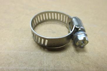
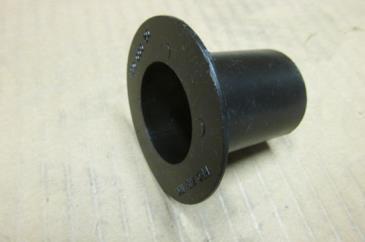
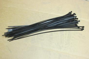
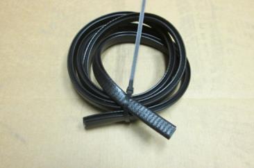
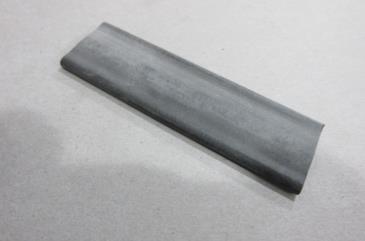
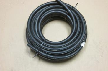
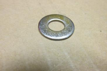
3 PREPARATION NOTES THE FOLLOWING ARE SUPPLIED IN YOUR KIT FOR GENERAL USE THROUGHOUT THE INSTALLATION: Vinyl Clad linestakes. These are used to attach hoses and wiring harnesses to the vehicle or other structure. There may be various types and sizes including 1, 2, 3, 2 double and 2 twisted. These are secured with self-tapping screws to the vehicle or other structure. These screws will require a screwgun/power screwdriver for installation. Tie Wraps (also called cable ties, cable wraps, wire ties, zip ties). These are used to secure bundles of hoses or wiring harnesses together. They are NOT used to secure hoses and wiring to the vehicle. These are 14 plastic. There are also stainless steel 14 tie wraps supplied for securing the fire protective sleeve to the refrigerant hoses/heater hoses that run near OEM equipment. Hose Clamps (wormgear clamps) used on hoses, #10 and 7/8 Wire Loom (Convoluted Tube). This comes in 1/4, 1/2, 3/4, and 1 sizes and is used to protect wiring and hoses at various points in the vehicle. It is easily cut to length. Trim Lock. Used to trim metal openings and edges. Various specialty hardware including grommets, plates, spacers and shims. Various general hardware including screws, bolts, washers, lock washers and nuts. Self-Tapping 14 x 1 screws ( ) are used frequently. Plumbing fittings including nipples, wyes, ells, splices, manifolds and O rings. Electrical wiring of various sizes and lengths including wiring harnesses. Hoses 5/8 heater, 7/8 drain and #6, #8 and #10 refrigerant. LLC Rev A 08/13 Page 3 of 43

 for wiring use. These are attached to bare wire and crimped.")

4 IN ADDITION TO AN ASSORTMENT OF GENERAL TOOLS AND SUPPLIES, THE CUSTOMER WILL NEED THE FOLLOWING: Silicone Seal (as applied by a caulk gun) for sealing access holes and providing some protection for hoses in various places. Mineral Oil for use on the O rings associated with each refrigerant hose fitting and the drier connections. Refrigerant Fittings Crimp Tool. If you do not have this tool, take a fitting from your kit with you to your local auto supply store for help in obtaining a tool. An assortment of different size eyelet lugs (terminal rings) for wiring use. These are attached to bare wire and crimped. The lugs are then attached to screw terminals on devices and boards or attached to the vehicle chassis with self-tapping screws. An assortment of butt splices. These are used to join bare wires to make connections. They are crimped. Once crimped they should be weather proofed. If you use Perma-Seal Butt Connectors you can simply use a heat gun or torch to shrink the cover around the connection to seal it. If you use standard butt connectors, you will need to slip a piece of shrink tubing (customer supplied) over one wire, do your crimp, slide the shrink tubing over the connection and heat/seal with a torch or heat gun. LLC Rev A 08/13 Page 4 of 43

5 Please read the following notes before beginning installation: Parts Numbers for parts will be noted the first time the parts are referred to in the instructions only. Plumbing and electrical wiring often run in parallel so installation involves some switching back and forth between plumbing and electrical. Diagrams are provided at the end of these instructions, illustrating the air conditioning path, the heating path and the wiring runs for the installation. You may follow them as you read these instructions. Pictures of all the parts noted on the Parts List are included at the end of the instructions. Using the zoom tool (+ symbol) allows you to magnify pictures (assuming you are viewing this document on a computer and not as a printout). This may provide some additional clarification on some pictures. Also, if you print these instructions, note that several items are in color so a color copy is best. When installing refrigerant lines, if you install one end but do not immediately install the other end, cover that end with a cap or tape (electrical) to keep out contaminates. As you unpack your kit, locate the install label ( ) and record your kit number on it. Also, as you unpack your Evaporator you need to note the serial number for this unit on the label as well. (Note: You will need these numbers if you ever have to call ProAir for service). Remove the air cleaner before beginning installation. Reinstall after system installation. When installing a wye plumbing fitting, note that there is one inlet port and two oulett ports and the angle outlet port should be directed away from the inlet port as shown below. GENERAL RULE: AVOID CONTACT AS MUCH AS POSSIBLE WITH OEM EQUIPMENT AS YOU PROCEED WITH THE INSTALL (KEEP ITEMS YOU INSTALL AWAY FROM ORIGINAL EQUIPMENT COMPONENTS). LLC Rev A 08/13 Page 5 of 43
6 PARTS LIST Item # Part # Qty Description Harness, Wire 23 3-Speed Harness, Resistor, AirTech/Mini Max Relay, 40 Amp Harness, 20 Amp Power Relay Wire, 6 Gauge Red Switch, Rocker 11 Nissan Rear-Mode Switch, Rocker 11 Nissan Rear-Blower Harness, 11 Nissan Mode/Blower Switch Harness, Water Valve Electric 2-Port Linestake, Washer, Lock 8mm Clamp, Drain Hose 7/ Trim Lock, 2/ Wire Tie, 14 x 3/ Grommet, 1 Hose, 1 1/4 OD Screw, 14x1 Hex Washer Tek Zinc Washer, Lock 6mm Bolt, 8mm 1.25 x 75 Hex Head Wire Tie, 14 Stainless Steel Washer, 5/16 Flat Stainless Steel Clamp, #10 Heater Hose Washer, 6mm Spacer, 13/32 x 23/32 SRB Rubber Bolt, 6mm-1.0x60mm Zinc Part Th Hose, 1/2" ID Drain Hose, 5/8 ID OEM Spec-Bulk Hose, 5/16 Refrigerant #4890 Redu Barrier CF, Hose, 1/2 Refrigerant #4890 Redu Barrier CF, Wye, 5/8 OD Water, Plastic Valve, Kazoo 5/8 ID Straight Splice (Service Port), #6 FOR x 6 CF Ell, 90 #6 FOR x CF Ell, 90 #10 FOR x 10 CF Valve, Water, Electric 2-Port Fitting, Block, Liquid Tie-In 11 Nissan Fitting, Block, Suction Tie-In 11 Nissan Tape, Prestite, Refrigerant Sleeve, Fire Protective, 2 I.D O-Ring, Slimline # O-Ring, #6 (006.8MG) CV23 LLC Rev A 08/13 Page 6 of 43
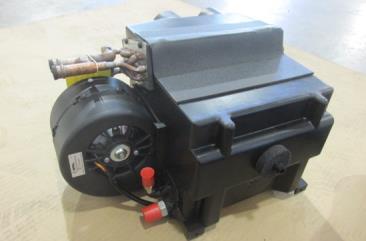
7 Label, Refrigerant Capacity, Blank Label, Anti-Freeze Mix Label, Door Jamb Card, Information, Warranty Registration Evaporator, AirTech II LLC Rev A 08/13 Page 7 of 43


 is to be mounted to the floor of the vehicle, installed on the rear side of the rear wheel well on the driver side.")
8 INSTALLATION INSTRUCTIONS It is advisable that you read through these instructions completely before beginning a step-by-step installation. The ProAir Tie-In System is a supplemental Air Conditioning/Heating system for the Nissan NV. The Tie-In system has its own Evaporator but ties in to the OEM system using its Compressor and Condenser to drive the A/C side of the system. The heating side ties in to the OEM system, using the same heated water from the engine that the OEM system does. Diagrams 1 and 2 at the end of these instructions show A/C and Heating Flow. REAR COMPARTMENT TO MID-BODY INSTALLATION (EVAPORATOR, HOSES, AND HARNESS) 1. The AirTech II Evaporator ( ) is to be mounted to the floor of the vehicle, installed on the rear side of the rear wheel well on the driver side. Figure 1 shows the location (X) while Figure 2 shows a finished installation. X Figure 1 Figure 2 2. A drain stub is located on the bottom of the unit (Figure 3) Place the unit in the vehicle in the location noted in Figure 1 (X) and mark the location for a hole in the floor of the vehicle for the drain. Drill a hole slightly larger than the drain stub. Figure 2 shows a finished installation. However, the Evaporator will not be mounted until the hoses are run. Drain Stub Figure 3 LLC Rev A 08/13 Page 8 of 43
(Figure 4).")
. Take the bundle inside the vehicle. Figure 4 4.")


9 3. Stretch out the two 5/8 heater hoses ( ), the #6 ( ) and #10 ( ) refrigerant hoses, and the Evaporator harness ( )(Figure 4). Mark one of the heater hoses with Red electrical tape (or in some other way) at intervals to designate it as the Evaporator inlet hose (Figure 4 Inset). Take the bundle inside the vehicle. Figure 4 4. Before beginning installation of the refrigerant hoses observe the following: A green gasket is supplied for each refrigerant hose fitting and mineral oil must be applied to the gasket before insertion in the fitting. This can be obtained at a local auto supply store (Figure 5). On the hose connection end, a special crimp tool must be used to crimp the rings. That tool must be obtained at a local auto supply store (Figure 6). Figure 5 Figure 6 LLC Rev A 08/13 Page 9 of 43

(figure 7).")
(figure 7).")
.")
10 5. Attach the refrigerant hoses to the AirTech II Evaporator. Remove the plastic caps on the refrigerant ports. Install fitting (straight) on the #6 hose and attach to the top port (liquid)(figure 7). Install fitting (90 degree) on the #10 hose and attach to the bottom port (suction)(figure 7). After installation, wrap the connections with Prestite tape to minimize condensation (Figure 8). Remember to apply mineral oil to the gaskets before inserting in the fittings. Liquid Port Suction Port Prestite Tape Figure 7 Figure 8 6. Prepare to install the two heater hoses. Remove the black plugs from the heat lines (Figure 9), observing the warning tag (Figure 10). Plugs Figure 9 Figure 10 LLC Rev A 08/13 Page 10 of 43


(Figure 12).")

11 7. Attach the two (2) heater hoses to the heating ports. Connect the hose with Red tape to the bottom port, Evaporator inlet (coolant from engine). Connect the other hose to the top port, Evaporator outlet (coolant to engine)(figure 11). Secure the hoses with clamps ( )(Figure 12). Figure 11 Figure Mount the Evaporator to the floor of the vehicle. Insert two (2) spacers ( ) under the tabs and secure with two self-tapping screws ( ). (Figures 13 and 14). Figure 13 Screws Figure 14 LLC Rev A 08/13 Page 11 of 43

 onto the drain stub (Figure 16).")
 over the kazoo valve and secure the")
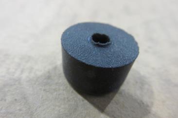
12 9. Connect the drain hose. Figure 15 shows the drain stub extending through the hole previously created in the floor of the vehicle. Insert hose (Figure 16) onto the drain stub (Figure 16). Insert kazoo valve (Figure 16) over the hose. Slip clamp (Figure 16) over the kazoo valve and secure the valve/hose assembly to the drain stub (Figure 17). Drain Stub Hose Kazoo Valve Figure 15 Figure 16 Figure 17 LLC Rev A 08/13 Page 12 of 43
 to the")
 wires to the blower motor pigtail")

13 10. Prepare the Evaporator wiring. Connect the Mini Harness Assembly (Figure 18) to the Evaporator. One end has two (2) plugs. Connect the plug with two (2) wires to the blower motor pigtail on the Evaporator (Figure 19). Figure 18 Figure Connect the second plug to the side panel of the Evaporator (three spade connections)(figure 20). Figure 20 LLC Rev A 08/13 Page 13 of 43
.")
.")

14 12. Mate the connector on the Mini harness with the connector on the Evaporator harness (Figure 21). Attach the ground wire on the Mini Harness to the chassis with a self-tapping screw (Figure 22). Figure 23 shows the completed wiring on the Evaporator end. Evaporator Harness Figure 21 Figure 22 Mini Harness Figure 23 LLC Rev A 08/13 Page 14 of 43
(figure 24).")
 to keep the bundle together between linestakes (Figure 25).")
 holes in the floor of the vehicle on the front side of the wheel well for the hoses to exit the")

15 13. Gather the refrigerant hoses (2), heater hoses (2), and Evaporator harness into a bundle and route them over the wheel well (to the front side)(figure 24). Secure the bundle with linestakes ( ) to the inner side wall of the vehicle (Figure 25). Use tie wraps ( ) to keep the bundle together between linestakes (Figure 25). Figure 24 Figure 25 Linestake Tie Wrap 14. Drill four (4) holes in the floor of the vehicle on the front side of the wheel well for the hoses to exit the passenger compartment to the underside of the vehicle. Install grommets ( ) in the holes. The Evaporator harness exits the vehicle in the hole with the #6 refrigerant hose. Figure 26 shows the holes in the floor of the vehicle while Figure 27 shows the finished installation. Figure 28 shows dimensions for drilling. Figure 26 Figure 27 Grommets Wall Wheel Well Holes 1.00 from wall Figure 28 LLC Rev A 08/13 Page 15 of 43

 to protect the hoses and harness (Figure")

16 15. Drill a hole in the inner side wall under the vehicle to allow the hoses between the side walls to exit to the underside of the vehicle. Figures 29 and 30 show the hoses exiting the wall cavity to the underside. Trim the hole with Trim Lock ( ) to protect the hoses and harness (Figure 31). Figure 32 shows the dimensions for drilling the hole. Figure 29 Figure 30 Side Wall Side Wall Figure 31 Trim Lock Floor Wheel Well Figure Hole LLC Rev A 08/13 Page 16 of 43


17 16. The method of drilling four (4) holes between the two side walls provides for a more compact installation as the hoses are close to the wall in the passenger compartment. An alternative method is to drill one large hole for all four hoses and the Evaporator harness to route through. This hole would be drilled in the floor and would not be inside the wall cavity. Figure 33 shows the hole inside the vehicle and Figure 34 shows it under the vehicle. A large grommet could be inserted in the hole or use Trim Lock to provide protection for the hoses/harness. The hoses can be covered with a box for protection and aesthetics. Figure 33 shows a transparent image of such an installation. Figure 33 Under Side of Floor Figure 34 LLC Rev A 08/13 Page 17 of 43
 for the Evaporator inlet and insert the Water Valve 05 000 852 in the path.")
. An arrow on the Water Valve indicates the direction of water flow (Figure 36).")
 plug to the Water Valve (Figure 37) and set aside the other end (has relay socket, fuse, and Pink wire/spade connector on")
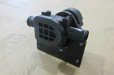
18 REAR COMPARTMENT TO MID-BODY INSTALLATION 17. With the four (4) hoses and Evaporator harness now under the vehicle, determine a path to the engine compartment. At some point along that path, cut the heater hose (marked with Red tape) for the Evaporator inlet and insert the Water Valve in the path. Mount the Water Valve to a cross member on the underside of the vehicle using two (2) self-tapping screws ( )(Figure 35). Secure the heater hose to the Water Valve inlet and outlet with clamps ( ). An arrow on the Water Valve indicates the direction of water flow (Figure 36). The Water Valve inlet fluid comes from the engine and flows to the Evaporator. Figure 35 To Evaporator (Water Valve Out) From Wye In Engine Compartment Figure Connect the Water Valve harness ( ) plug to the Water Valve (Figure 37) and set aside the other end (has relay socket, fuse, and Pink wire/spade connector on it)(figure 38). Figure 37 Figure 38 Pink Wire Fuse Relay Socket LLC Rev A 08/13 Page 18 of 43


.")
19 19. Route the hoses and Evaporator harness the remainder of the way to the engine compartment. Attach the bundle appropriately to cross members with linestakes and wire ties between linestakes (Figures 39 and 40). Care should be taken to not disturb any OEM equipment. Figure 39 Figure As the bundle enters the engine compartment, it needs to be protected from any heat generated by the engine. A fire resistant sleeve ( ) and two (2) stainless steel wire ties ( ) are provided to protect the hoses (Figure 41). Slip the hoses inside the sleeve and position appropriately to keep hoses away from heat. Secure sleeve to hoses/harness with the ties. Figure 42 shows the sleeve in place. Figure 41 Figure 42 LLC Rev A 08/13 Page 19 of 43

 THE OEM A/C SYSTEM BEFORE PROCEEDING!!! 21.")
 and bolt into place with bolt 02 000 232.")
. The other O-Ring slips on a similar groove on the OEM line. The OEM line will have an O-Ring in place when the line is broken.")
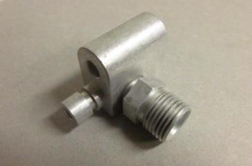
20 ENGINE COMPARTMENT COOLING A Tie-In System involves taking the OEM Drier outlet to a ProAir Liquid Tie-In fitting which sends the liquid refrigerant to both the OEM Evaporator and the ProAir Evaporator. The outputs from both Evaporators are tied together in a ProAir Suction Tie-In fitting which connects to the Compressor Suction port (See Diagram 1 at the end of these instructions). EVACUATE (DISCHARGE) THE OEM A/C SYSTEM BEFORE PROCEEDING!!! 21. Disconnect the OEM hard refrigerant line (suction) located to the driver side in the engine compartment by removing and discarding the OEM bolt (Figure 43). Separate the line and insert the Suction Tie-In fitting ( ) and bolt into place with bolt Slide lock washer and washer on the bolt before installing (Figure 46). But before inserting the tie-in, install two (2) O-Rings ( ). One O-Ring slips on the groove on the fitting (Figure 45). The other O-Ring slips on a similar groove on the OEM line. The OEM line will have an O-Ring in place when the line is broken. Remove and discard it. Install the O-Ring supplied with the kit (Figure 45). Attach fitting to the refrigerant hose (#10) coming from the ProAir Evaporator (outlet) and connect to the Suction Tie-In. (Figure 44). Remember to apply mineral oil to all O-Rings before inserting in the fittings. Remove/Discard Bolt Evaporator Out Tie-In Fitting Figure 43 Figure 44 Groove Figure 45 Figure 46 LLC Rev A 08/13 Page 20 of 43
. Separate the line and insert ProAir Liquid Tie-In fitting 05 001 001.")
 O-Rings (08 000 163). One O-Ring slips on the groove on the fitting (Figure 49).")
.")
. Remember to apply mineral oil to all O-Rings before inserting in the fittings.")
21 22. Disconnect the OEM hard refrigerant line (liquid) located to the passenger side in the engine compartment (near the radiator) by removing and discarding the OEM bolt (Figure 47). Separate the line and insert ProAir Liquid Tie-In fitting Secure the fitting with bolt Slide lock washer and washer on the bolt before installing (Figure 50). But before inserting the tie-in, install two (2) O-Rings ( ). One O-Ring slips on the groove on the fitting (Figure 49). The other O-Ring slips on a similar groove on the OEM line. The OEM line will have an O-Ring in place when the line is broken. Remove and discard it. Install the new O-Ring supplied with the kit (Figure 49). Attach fitting to the refrigerant hose (#6) running from the ProAir Evaporator (inlet) and connect to the Liquid Tie-In (Figure 48). Remember to apply mineral oil to all O-Rings before inserting in the fittings. Tie-In Fitting Evaporator In Remove/Discard Bolt Figure 47 Figure 48 Groove Figure 49 Figure 50 LLC Rev A 08/13 Page 21 of 43
 line and the OEM Heater Return (outlet) line.")
.")
 and connect the two hose ends to the inline ports of the wye (Figure 52) and clamp (02 000 390).")
22 HEATING 23. The Tie-In to the heating system is accomplished by inserting a wye in both the OEM Heater Push (inlet) line and the OEM Heater Return (outlet) line. Locate the OEM Heater lines on the firewall on the passenger side (Figure 51). The line on the passenger side is typically the Push line (but verify this for your vehicle). Use vise grips or some other kind of tool to clamp off the line (Figure 52). Do this procedure with a cool engine to prevent injury. Cut the line and insert the wye ( ) and connect the two hose ends to the inline ports of the wye (Figure 52) and clamp ( ). Make sure the angle port on the wye is pointing in the direction of water flow. Heater Lines Wye Vise Grips Figure 51 Figure Connect the Water Valve inlet hose (marked with the Red tape) to the angle port on the wye (Figure 53) and clamp. Remove the vise grips. Figure 53 LLC Rev A 08/13 Page 22 of 43

 line to the angle port on the wye and clamp (Figure 55).")
23 25. Follow the Return hose to the driver side (Figure 54) and repeat the process of clamping off the hose, cutting the hose, and inserting a wye. Connect the cut ends to the inline ports of the wye and clamp. Connect the Evaporator outlet (return) line to the angle port on the wye and clamp (Figure 55). Remove the vise grips. From OEM Evaporator To Radiator Figure 54 Figure 55 LLC Rev A 08/13 Page 23 of 43
 relays connected to wire harnesses (two of those")
 switches: Mode (A/C or Heat), Blower (Fan Speed-High, Med, or")
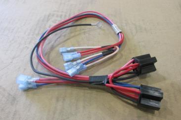
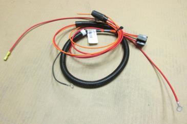
24 ELECTRICAL OVERVIEW 26. The electrical system requires the interconnection of the following: Four (4) relays connected to wire harnesses (two of those have fuses attached), Figure 56 Evaporator harness running from the Evaporator at the back of the vehicle, Figure 57 Water Valve Harness running from the Water Valve, Figure 57 Two (2) switches: Mode (A/C or Heat), Blower (Fan Speed-High, Med, or Low), Figure 58 Water Valve Harness Evaporator Harness Figure 56 Figure 57 Figure 58 LLC Rev A 08/13 Page 24 of 43
25 27. Figure 59 illustrates the components. TIE-IN SYSTEM Fuse 20 Amp Power (Ignition) Relay # 1 Switch Relay (Cool) #2 Switch Relay (Heat) #3 Fuse 5 Amp Water Valve Relay #4 Wiring To Passenger Compartment Battery Ignition Evaporator Harness Water Valve Harness Figure 59 LLC Rev A 08/13 Page 25 of 43
 should be installed inside the passenger compartment while the others may be installed")
 while Figure 61 shows")

 just snaps in.")
26 PREPARATION 28. Physical location of the four (4) relays must be determined. The Switch relays (Relays #2 and #3) should be installed inside the passenger compartment while the others may be installed in the passenger compartment (preferred method) or the engine compartment. Figure 60 shows the passenger compartment area where the units would be installed (glove box removed) while Figure 61 shows an area where they could be installed in the engine compartment on the firewall. These instructions will illustrate installation of all relays in the passenger compartment. Figure 60 Figure Remove the side panel and the glove box in the passenger compartment on the passenger side. The side panel (Figure 62) just snaps in. The glove box requires removal of seven (7) screws, three (3) on the bottom (Figure 63) and four (4) screws exposed when the unit is opened (Figure 64). Set the glove box aside (Figure 65). Glove Box Side Panel Remove Figure 62 Figure 63 LLC Rev A 08/13 Page 26 of 43


 for the wiring to route between")

27 Figure 64 Remove Figure Find locations for all the relays. Figure 66 shows the general layout: #1, OEM switch panel, Figure 66 #2, Relay #1 (Ignition) and Relay #4 (Water Valve), Figure 67 #3, Relay #2 and Relay #3 (Switch Relays), Figure 68 #4, Hole (in firewall) for the wiring to route between the engine and passenger compartments, Figure Figure 66 Figure 67 Figure 69 Figure 68 LLC Rev A 08/13 Page 27 of 43


28 INSTALLATION 31. Drill a hole in the firewall to allow wires to route between the engine compartment and the passenger compartment (Figures 70 and 71). The hole must be big enough to allow passage of the ignition wire, battery wire, and two wiring harnesses (Evaporator and Water Valve). Trim the hole with Trim Lock (behind the insulation). Route the Evaporator and Water Valve harnesses through the hole in the firewall into the passenger compartment. Figure 70 Figure Install an eyelet lug on one end of the 6 gauge wire Route the other end through the hole in the firewall into the passenger compartment (Figure 72). This end is to be butt spliced to the fuse wires on Relays #1 and #4 later. Figure 72 LLC Rev A 08/13 Page 28 of 43
, connects to harness 01 000 239 (20 Amp Fuse attached) Relays #2 and #3 (Switch Relays), connect to harness 01 000 634 Relay #4, Water Valve, connects to harness 01 000 644")
 to attach to OEM compartment (Figures 75, 76, and 77).")
29 33. Attach four (4) relays ( ) to relay harnesses (Figure 73). Number/label them as noted below (Figure 74). (Numbering will be referred to throughout the instructions). Relay #1, Power (Ignition), connects to harness (20 Amp Fuse attached) Relays #2 and #3 (Switch Relays), connect to harness Relay #4, Water Valve, connects to harness (routed from engine compartment)( 5 Amp Fuse attached) Figure 73 Figure Mount the relays/fuses in the locations selected. Use self-tapping screws ( ) to attach to OEM compartment (Figures 75, 76, and 77). Route the Relay #1 (Power, Ignition) Orange wire (Signal In) through the firewall hole into the engine compartment (Figure 78). Power and Water Valve Relays Screws Figure 76 Relays Figure 75 LLC Rev A 08/13 Page 29 of 43
 and insert the Rear Mode switch (Heat-A/C) 01")
. Figure 80 Figure 79 36.")

30 Ignition Wire Switch Relays Figure 77 Figure Remove the OEM switch plate from the dash (Figure 79) and insert the Rear Mode switch (Heat-A/C) and the Rear Blower switch (Fan Speed-High, Med, Low) into the plate. The Mode switch should be on the left as viewed from the front (Figure 80). Figure 80 Figure Note the numbering of the terminals on the rear of the switches (Figure 81). This information will be used when connecting the wiring to the switches. The connections are spade terminals: Blower Mode Figure 81 Rear View LLC Rev A 08/13 Page 30 of 43

31 37. Connect the wiring in the passenger compartment by following Figures 82, 83 and 86. Relay wiring is noted on Figure 82. Figure 83 includes the wiring from the harnesses/wire from the engine compartment. Figure 86 notes wiring involving the relays and will include some wiring already completed or wiring that does not need to be done (loops noted in the Connection column). There is some duplication in the instructions but this serves as system documentation. RELAY WIRING Figure 82 Relay Plugs into Harnesses , , , , Power Relay Grnd Sig In Relay with tab side down looking on end: 1 Power Out / Red or Red/White Stripe 2 Ground / Black 3 Signal In / Orange, Blue or Pink 4 Power In / Red 5 Power In / Red (not always used) Pwr In Relay Schematic Pwr Out LLC Rev A 08/13 Page 31 of 43

 Terminal 1 Not Used Terminal 2")
32 Figure 83 WIRING HARNESSES, SWITCHES WIRING EVAPORATOR HARNESS, Yellow wire Connect to Blower Switch, Terminal #1 Red wire Connect to Blower Switch, Terminal #3 Orange wire Connect to Blower Switch, Terminal #6 WATER VALVE HARNESS, Relay socket Connect to Relay #4 Red wire/fuse Butt splice to 6 gauge Red wire going to the battery in the engine compartment Remove spade connector on this wire and the spade connector on the short Pink Pink wire wire on Relay #3 harness (Switch Relay #2, Heat, Signal In). Butt splice these two wires together with the Red/White Stripe wire running from the Booster Pump Black wire Ground to vehicle chassis MODE SWITCH (Spade Connections) Terminal 1 Not Used Terminal 2 Connect one end of White/Orange jumper wire here, other end to Terminal 4 Terminal 3 Connect long Blue wire of Relay #2 harness here (Switch Relay #1, A/C, Signal In) Terminal 4 Connect one end of White/Orange jumper wire here, other end to Terminal 2 Terminal 5 Connect Red wire of Relay#3 here (Switch Relay #2, Heat, Power In) Terminal 6 Connect long Pink wire on Relay #3 here (Switch Relay #2, Heat, Signal In) BLOWER SWITCH (Spade Connections) Terminal 1 Connect Evaporator harness Yellow wire here Terminal 2 Connect one end of White/Orange jumper wire here, other end to Terminal 4 Terminal 3 Connect Evaporator harness Red wire here Terminal 4 Connect one end of White/Orange jumper wire here, other end to Terminal 2 Terminal 5 Connect Red/White Stripe wire of Relay #2 here (Switch Relay #1, Power Out) Terminal 6 Connect Evaporator harness Orange wire here 38. Figures 84 and 85 illustrate the wiring on the back of the switches. Figure 85 shows the jumper referred to in Figure 83. Figure 85 Jumper Figure 84 LLC Rev A 08/13 Page 32 of 43
33 TIE-IN WIRING Figure 86 Relay Name Device Wire Color Harness? Signal Connects To Connection Power Fuse on Relay #1 Red Power In Battery, Positive Terminal** Eyelet Power Relay #1 Red Power In Fuse on Relay #1, Power Out Loop Power Relay #1 Red Power Out Relay #2, Power In, Red Wire Spade Power Relay #1 Orange Signal In Ignition Terminal Block in Engine Compartment*** Bare Wire Power Relay #1 Black Ground Chassis* Eyelet Switch Relay #2 Red Power In Relay #1, Power Out, Red Wire ( ) Spade Switch Relay #2 Red/White Power Out Blower Switch, Terminal #5 Spade Switch Relay #2 Red/White Power Out Relay #3, Power Out Loop Switch Relay #2 Blue (long) Signal In Mode Switch, Terminal #3, A/C Command Spade Switch Relay #2 Blue (short) Signal In not used Spade Switch Relay #2 Black Ground Relay #3, Ground Loop Switch Relay #3 Red Power In Mode Switch, Terminal 5 Spade Switch Relay #3 Red/White Power Out Relay #2, Power Out Loop Switch Relay #3 Pink (short) Signal In Relay #4, Signal In, Pink Wire ( ) Spade Switch Relay #3 Pink (long) Signal In Mode Switch, Terminal #6, Heat Command Spade Switch Relay #3 Black Ground Chassis* Eyelet W Valve Fuse on Relay #4 Red Power In Battery Positive Terminal** Eyelet W Valve Relay #4 Red Power In Fuse on Relay #4, Power Out Loop W Valve Relay #4 Red Power In Water Valve, Loop Plug W Valve Relay #4 Pink Signal In Relay #3, Signal In, Pink Wire Spade W Valve Relay #4 Purple Power In Water Valve Plug W Valve Relay #4 Black Ground Water Valve Plug W Valve Relay #4 Black Power Out Relay #4, Ground Loop W Valve Relay #4 Black Ground Chassis* Eyelet *All the ground (Black) wires are to be attached to the chassis with a self-tapping screw. **These wires are butt spliced to the #6 wire running through the hole in the firewall to the battery. ***To be connected later. LLC Rev A 08/13 Page 33 of 43


34 39. Reinstall the OEM panel into the vehicle as in Figures 87 and 88. Figure 87 Figure Reattach the side panel and the glove box. 41. The Orange wire (Signal In) on Relay #1 runs to the Ignition terminal compartment in the engine compartment adjacent to the battery. Remove the cover (Figure 89) and create a notch for the wire to enter the unit (Figure 90). Install a spade lug on the end of the wire and install in the position shown in Figure 91. Reinstall the cover. Figure 89 Ignition Terminal Notch Figure 90 LLC Rev A 08/13 Page 34 of 43

.")
35 Figure In the engine compartment, attach the 6 gauge (Red) wire to the positive terminal of the battery (Figure 92). Figure 92 LLC Rev A 08/13 Page 35 of 43
(figure 93), and the firewall hole. Also seal anywhere where hoses come up against OEM equipment (if any). 44.")
 pound over factory specifications (noted on a label in the engine compartment or on the door jamb).")
36 43. To finish the install, use silicone to seal around all holes made in the vehicle including the Evaporator drain hose hole, the refrigerant hoses/heater hoses/evaporator harness bundle holes (in the floor and inner side wall of the vehicle)(figure 93), and the firewall hole. Also seal anywhere where hoses come up against OEM equipment (if any). 44. Remove the protective cover over the Evaporator Fan (Figure 94). Figure 93 Figure Refrigerant can now be added to the system at the rate of one (1) pound over factory specifications (noted on a label in the engine compartment or on the door jamb). No additional PAG oil over factory specs is needed. 46. Several informational labels are provided to document installation and provide those who service the system with proper maintenance information. Those are: This label should note the new refrigerant and PAG oil capacity of your system. It should be applied somewhere in the engine compartment This label notes the anti-freeze mixture ratio and should also be applied in the engine compartment This label provides information as to date of installation and the installer s name. The serial number for the Evaporator is noted here as well as your kit number. It should be attached to the driver side door jamb. LLC Rev A 08/13 Page 36 of 43


37 PARTS LLC Rev A 08/13 Page 37 of 43


38 LLC Rev A 08/13 Page 38 of 43


39 LLC Rev A 08/13 Page 39 of 43
40 A/C FLOW NISSAN NV, TIE-IN (AirTech II) Diagram 1 COMPRESSOR (OEM) CONDENSER (OEM) DRIER (OEM) Discharge OEM In Out OEM In Out OEM OEM Suction OEM Suction Tie-In/ O-Ring (ProAir) OEM EVAPORATOR (OEM) Out In OEM Liquid Tie-In/ O-Ring (ProAir) Fitting Fitting #10 Hose Fitting EVAPORATOR (ProAir) Out In Fitting #6 Hose Drain Hoses Notes: Part Numbers for fittings for hoses connecting to devices are noted. #6 Hose-5/16 =PN , #8 Hose=13/32 =PN , #10 Hose=1/2 =PN Fittings require a special crimp tool. Fittings come with a green gasket. Gasket should have mineral oil applied to it before installation. LLC Rev A 08/13 Page 40 of 43
41 Diagram 2 HEATING FLOW AIRTECH II EVAPORATOR In WATER VALVE Out In From Engine (Push Line) To Radiator (Return Line) Wye Wye IN OEM HEATER (Dash) OUT EVAPORATOR Out Notes: Dotted lines above represent original (OEM) installed hose Kit installed hose is 5/8 standard heater hose PN LLC Rev A 08/13 Page 41 of 43
42 Diagram 3 ELECTRICAL LAYOUT / TIE-IN SYSTEM Ignition 20 Amp Fuse Relay #1 (Ignition) Signal In Power In/Power Out Ground Mode Switch Not Used BAT Relay #2 (SW #1) Signal In Power In/Power Out Ground 5 Blower Switch Evaporator Low Med High Relay #3 (SW #2) 5 Amp Fuse Signal In Power In/Power Out Ground Relay #4 (W Valve) Signal In Power In/Power Out Ground Water Valve Black NOTES: Wire cross points do not represent connections. Wires that T are butt spliced. Ground wires can be individually grounded to the vehicle chassis or can be daisy-chained together in any fashion and then grounded.. Red Purple LLC Rev A 08/13 Page 42 of 43
43 CUSTOMER NOTES: LLC Rev A 08/13 Page 43 of 43
INSTALLATION INSTRUCTIONS FOR. Plumbing/Electrical. For Sprinter Evaporator 560 / Digital Control
 INSTALLATION INSTRUCTIONS FOR Plumbing/Electrical For Sprinter Evaporator 560 / Digital Control Corporate Headquarters ProAir, LLC 28731 County Road 6; Elkhart, IN 46514 Phone: (574) 264-5494; Toll Free:
Warning Do not attempt to install A/C units unless you are experienced with servicing A/C systems!
 TOOLS REQUIRED: INSTALLATION INSTRUCTIONS PT-A-406 Rear HVAC System for 2014-2018 RAM PROMASTER without OEM rear AC/Heat Prep Package Fittings ***This system can also be used for a Promaster van with the
PRODUCT: Install Instructions, MV-1 C/O Std, With Aux Fan RELEASE DATE: 2/28/14 REVISION DATE: 9/30/2014 PART NUMBER: Rev C
 Parts List (1) 01 000 027 Switch, 4 Position Blower (1) 04 000 007 Hose, 1/2 ID Drain, 6 (1) 01 000 087 Harn, Resistor (1) 04 000 078 Tube, Convo 1/2 x 24 (2) 01 000 136 Relay, 40 Amp (1) 04 000 015 Hose,
PERFECT FIT SERIES IN-DASH HEAT/ COOL/ DEFROST 1969 CHEVROLET CAMARO/ FIREBIRD NOTE: INSTRUCTIONS DEPICT CAMARO
 specializing in AIR CONDITIONING, PARTS AND SYSTEMS for your classic vehicle PERFECT FIT SERIES IN-DASH HEAT/ COOL/ DEFROST 1969 CHEVROLET CAMARO/ FIREBIRD NOTE: INSTRUCTIONS DEPICT CAMARO CONTROL & OPERATING
& 76 CHEVROLET NOVA HEATER ONLY
 specializing in AIR CONDITIONING, PARTS AND SYSTEMS for your classic hi l PERFECT FIT IN-DASH HEAT/ COOL/ DEFROST 1969-74 & 76 CHEVROLET NOVA HEATER ONLY CONTROL & OPERATING INSTRUCTIONS The controls on
Installation Instructions for Lingenfelter GM 2500 Suburban & Yukon XL Auxiliary Fan System (with AC clutch controlled fan output)
") Installation Instructions for Lingenfelter 2007-2013 GM 2500 Suburban & Yukon XL Auxiliary Fan System (with AC clutch controlled fan output) PN L300080607 Revision - 1.1 Lingenfelter Performance Engineering
Installation Instructions for Lingenfelter 2007-2013 GM 2500 Suburban & Yukon XL Auxiliary Fan System (with AC clutch controlled fan output) PN L300080607 Revision - 1.1 Lingenfelter Performance Engineering
PERFECT FIT SERIES IN-DASH HEAT/ COOL/ DEFROST MUSTANG
 specializing in AIR CONDITIONING, PARTS AND SYSTEMS for your classic vehicle PERFECT FIT SERIES IN-DASH HEAT/ COOL/ DEFROST 1969-70 MUSTANG CONTROL & OPERATING INSTRUCTIONS The controls on your new Perfect
PERFECT FIT IN-DASH HEAT/ COOL/ DEFROST FORD FAIRLANE & CROWN VICTORIA
 PERFECT FIT IN-DASH HEAT/ COOL/ DEFROST 1955-56 FORD FAIRLANE & CROWN VICTORIA CONTROL & OPERATING INSTRUCTIONS The controls on your new Perfect Fit system, offer complete comfort capabilities in virtually
INSTALLATION & OWNER S MANUAL
 1 of 18 INSTALLATION & OWNER S MANUAL (*Not including cab & other accessories) A/C Alternator Kit: Yamaha Drive & Drive2 P/N: 1ACYDR2DRK Recommended it be installed with Curtis Cab: Sandstone (p/n 1GCYD1-A,
jegs.com
 Contents Wiring Harness w/ Fuse Panel Installation Instructions Turn Signal Plug w/ Terminals 2 Headlight Plugs 3/4 Grommet 10 ¼ Terminals 4 Ring Terminals 10 Wire Ties Fusible Link 2 Screws & Nuts 2 Plastic
Installation Instructions
 Installation Instructions Jeep JK Unlimited (2007 Present) Mounting Bracket and Air Line System Kit for ARB On-Board Twin Air Compressor (CKMTA12) Made in the USA Kit Contents: 1 Bracket for ARB Compressor
1. Disconnect the battery. This is important! This will prevent air bag deployment.
 PARTS PACKING LIST Evaporator assembly Drain tube Plastic air plug Hardware package 11040 3601 W. Clarendon Phoenix, Arizona 85019 (602) 233-0090 800-648-4475 www.ackits.com 2003-4 Jeep Wrangler EVAPORATOR
Air Conditioner for M915 A0/A1 Truck
 RD-2-4530-0 Air Conditioner for M915 A0/A1 Truck INSTALLATION INSTRUCTIONS Install refrigerant compressor per instructions provided with compressor mount kit. CAUTION: Edges of sheet metal can be sharp!
INSTALLATION INSTRUCTIONS FOR COZY CAB A-1 AIR CONDITIONING KIT
 INSTALLATION INSTRUCTIONS FOR COZY CAB A-1 AIR CONDITIONING KIT 05-11 INSTALLATION INSTRUCTIONS A-12235 Air Conditioner Kit Cab set up instructions; This air conditioning kit is designed to be used with
1963 GEN IV SUREFIT VINTAGE AIR CONDITIONING INSTALLATION
 by Randy Irwin 1963 GEN IV SUREFIT VINTAGE AIR CONDITIONING INSTALLATION Randy Irwin - Technical Writer Randy has been involved in the Chevy parts business for over 30 years. He is a wizard at creating,
Installation Instructions
 Installation Instructions Jeep JK 2-Door (2011 Present) Mounting Bracket and Air Line System Kit for ARB On-Board Twin Air Compressor (CKMTA12) Made in the USA Kit Contents: 1 Flat Bracket 1 Formed Bracket
Installation Tips for your Crimestopper/ProStart Remote Start system (add-on for GM vehicles) v1.02 updated 1/16/2013
 v1.02 updated 1/16/2013") Installation Tips for your Crimestopper/ProStart Remote Start system (add-on for GM vehicles) v1.02 updated 1/16/2013 Thank you for purchasing your remote start from MyPushcart.com - an industry leader
Installation Tips for your Crimestopper/ProStart Remote Start system (add-on for GM vehicles) v1.02 updated 1/16/2013 Thank you for purchasing your remote start from MyPushcart.com - an industry leader
Turn Signal / Horn Kit PN 7101 by All years Polaris RZR 1000 and RZR 900, 900-4, 900 trail, 900S and 900XC STOP - THIS KIT IS DESIGNED
 All years Polaris RZR 1000 and 1000-4 2015 RZR 900, 900-4, 900 trail, 900S and 900XC STOP - THIS KIT IS DESIGNED SPECIFICALLY FOR ALL YEAR AND MODEL POLARIS RZR 1000 AND 1000-4. ALSO THE 2015 POLARIS RZR
WirelessONE. Kit INSTALLATION GUIDE. Key Fob Activated Compressor System
 Kit 25870 Key Fob Activated Compressor System MN-751 (041202) ECR 7260 INSTALLATION GUIDE For maximum effectiveness and safety, please read these instructions completely before proceeding with installation.
80703 & Backside License Plate Mount for Jeep JK Wrangler (80707) & 10+ (80703)
 & 10+ (80703)") 80703 Backside Mount 80707 Backside Mount REQUIRED TOOLS 10mm SOCKET 13mm SOCKET 4mm HEX KEY WIRE CRIMPS WIRE STRIPPERS ELECTICAL TAPE SCREW DRIVER KIT CONTAINS BACKSIDE MOUNT LICENSE PLATE BRACKET WITH
80703 Backside Mount 80707 Backside Mount REQUIRED TOOLS 10mm SOCKET 13mm SOCKET 4mm HEX KEY WIRE CRIMPS WIRE STRIPPERS ELECTICAL TAPE SCREW DRIVER KIT CONTAINS BACKSIDE MOUNT LICENSE PLATE BRACKET WITH
Important information about your new a/c system. Please read the following directions prior to installing this a/c system.
 PAGE 1 Important information about your new a/c system. Please read the following directions prior to installing this a/c system. PN s: CK-7586258, CK-758642, CK-7586304, CK7586SBC, CK-7486NC Jeep CJ Series
Jeep Wrangler 4.0 Liter TJ Jeep Wrangler 2.5 Liter TJ Installation instructions
 TM www.jeepair.com 1999 Jeep Wrangler 4.0 Liter TJ 1999-2001 Jeep Wrangler 2.5 Liter TJ Installation instructions Kit Information After 1994 every vehicle was designed for R134a refrigerant. The Jeep kit
Backside License Plate Mount for Jeep JK Wrangler
 REQUIRED TOOLS 10mm SOCKET 13mm SOCKET 4mm HEX KEY WIRE CRIMPS WIRE STRIPPERS ELECTICAL TAPE SCREW DRIVER KIT CONTAINS BACKSIDE MOUNT LICENSE PLATE BRACKET WITH LEDS PLASTIC PASS-THROUGH GROMMET STAINLESS
INSTALLATION INSTRUCTIONS FOR THE TOMAHAWK ELECTRIC REVERSE
 INSTALLATION INSTRUCTIONS FOR THE TOMAHAWK ELECTRIC REVERSE LAST UPDATED: April 2018 Thank you for choosing the Motor Trike Electric Reverse. We ask that you read the directions before you start and follow
 Page 1 of 9 Home Account Contact ALLDATA Log Out Help DAN GRIMWOOD DAN GRIMWOOD00002 Select Vehicle New TSBs Technician's Reference Component Search: OK 1985 Dodge Truck D 350 Pickup V8-360 5.9L VIN I
Installation MKIV Headlight Housings with Fog Lamps (Procedures apply to both MKIV Jetta and Golf)
") Page 1 This tutorial is provided as a courtesy by ECS Tuning. Service Procedure Installation Proper service and repair procedures are vital to the safe, reliable operation of all motor vehicles as well
Page 1 This tutorial is provided as a courtesy by ECS Tuning. Service Procedure Installation Proper service and repair procedures are vital to the safe, reliable operation of all motor vehicles as well
Installation Manual P / P / P A / P B / P C E N G I N E B R A K E S
 Manual A p p l i c a t i o n : D e t r o i t D i e s e l S e r i e s 6 0 P - 6 1 / P - 6 3 / P - 6 3 A / P - 6 3 B / P - 6 3 C E N G I N E B R A K E S 5 If the engine is equipped with an aluminum valve
CUMMINS 6.7L EXHAUST BRAKE PRXB EXHAUST BRAKE KIT FOR 2007½-2015 TRUCKS EQUIPPED WITH 6.7L CUMMINS ISB DIESEL ENGINES. C Kit C Kit
 CUMMINS 6.7L EXHAUST BRAKE PRXB EXHAUST BRAKE KIT FOR 2007½-2015 TRUCKS EQUIPPED WITH 6.7L CUMMINS ISB DIESEL ENGINES C44038 4 Kit C44039 5 Kit BEFORE STARTING THE INSTALLATION please read the entire installation
Jeep Wrangler TJ. Complete Air Conditioning System. Slide Control Head. Installation instructions
 WWW.JEEPAIR.COM 1996-1998 Jeep Wrangler TJ Complete Air Conditioning System Slide Control Head Installation instructions Kit Information After 1994 every vehicle was designed for R134a refrigerant. The
Installation Tips Crimestopper/ProStart Remote Start system + PLJX + DLRM + SPDT (for GM vehicles) T0760 v1.1 updated 2/5/14
 T0760 v1.1 updated 2/5/14") Installation Tips Crimestopper/ProStart Remote Start system + PLJX + DLRM + SPDT (for GM vehicles) T0760 v1.1 updated 2/5/14 Thank you for purchasing your remote start from MyPushcart.com - an industry
Installation Tips Crimestopper/ProStart Remote Start system + PLJX + DLRM + SPDT (for GM vehicles) T0760 v1.1 updated 2/5/14 Thank you for purchasing your remote start from MyPushcart.com - an industry
2013 Road King CVO FLHRSE5 Detachable Fairing w/ Garmin Zumo 665 Installation Instructions
 2013 Road King CVO FLHRSE5 Detachable Fairing w/ Garmin Zumo 665 Installation Instructions 1 1. Turn ignition switch to on position and leave there. This will prevent alarm from going off when you disconnect
GENUINE PARTS INSTALLATION INSTRUCTIONS
 GENUINE PARTS INSTALLATION INSTRUCTIONS 1. 2. 3. 4. DESCRIPTION: Illuminated Kick Plate Kit APPLICATION: Murano PART NUMBER: 999G6 C2000, 999G6 C2100, 999G6 C2200 999Q9 AY001 - Accessory Service Connector
Chevrolet Truck Install Instructions. This kit is designed for the Chevrolet or GMC trucks without factory air conditioning.
 1967-1972 Chevrolet Truck Install Instructions This kit is designed for the 1967-1972 Chevrolet or GMC trucks without factory air conditioning. Glove box Heater box Heater box firewall cover Controls and
Signal Mirror Installation Instructions
 Signal Mirror Installation Instructions Ford F-250 to F-750 Pick-Up, Super-Duty 1998-2007 Trailer Tow Mirror Ford Excursion XLT/Limited 2000-2002 Trailer Tow Mirror Ford Excursion (all models) 2003-2005
Installation Tips for your Crimestopper/ProStart Remote Start system (for GM vehicles) v1.01 updated 2/27/2012
 v1.01 updated 2/27/2012") Installation Tips for your Crimestopper/ProStart Remote Start system (for GM vehicles) v1.01 updated 2/27/2012 Thank you for purchasing your remote start from MyPushcart.com - an industry leader in providing
Installation Tips for your Crimestopper/ProStart Remote Start system (for GM vehicles) v1.01 updated 2/27/2012 Thank you for purchasing your remote start from MyPushcart.com - an industry leader in providing
INSTALLATION AND USER MANUAL
 INSTALLATION AND USER MANUAL SDKIT-730 & SDKIT-734 100% Bolt-On 150 PSI Train Horn System for 2011-2015 F-250 & F-350 Super Duty P/N SDKIT-730 P/N SDKIT-734 Thank you for purchasing a Kleinn Air Horns
Installation Items: Cruise Module
 Installation Items: Rostra 250-1223, Electronic Cruise Control System (ECCS) includes the cruise module, harness, cruise cable, cruise module mounting bracket, cruise cable mounting bracket and hardware
GENUINE PARTS INSTALLATION INSTRUCTIONS
 GENUINE PARTS INSTALLATION INSTRUCTIONS 1. 2. 3. 4. DESCRIPTION: Security Light Kit APPLICATION: Altima Sedan (2013+) PART NUMBER: 999F4 AX010 - Universal Security Lighting Kit. KIT CONTENTS: Item QTY
3 in 1 TRAIL CHARGER with LOCKOUT
 Owner s Manual P/N: 283821 500 3 in 1 TRAIL CHARGER with LOCKOUT 283821 01 Version 2.04 07/05/2011 Owners Manual Operation Installation Wiring Diagram Troubleshooting Parts Breakdown 1 GENERAL OPERATION
Jeep Wrangler TJ 4.0 LITER Installation instructions
 www.jeepair.com 2002-2004 Jeep Wrangler TJ 4.0 LITER Installation instructions Kit Information These directions are for 2002-2006 model Jeep Wranglers. After 1994 every vehicle was designed for R134a refrigerant.
Ram 1500 Crew Cab A Ram 2500/3500 Crew Cab A
 I N S T A L L A T I O N G U I D E APPLICATION AMP Part # Ram 1500 Crew Cab 2013-2015 77138-01A Ram 2500/3500 Crew Cab 2013-2015 77138-01A Note:The application works only on the Crew Cab model Vehicles.
FOG LAMPS INSTALL KIT
 FOG LAMPS INSTALL KIT PT CRUISER INSTALLATION INSTRUCTIONS Read entire instructions thoroughly before starting. For proper aiming of fog lamps, follow procedures in the service manual. NOTES: Left and
WPS-104 Heater Installation Instructions For 500EFI, 700 XP, & Crew Applications
 WPS-104 Heater Installation Instructions For 500EFI, 700 XP, & Crew Applications ORDER OF INSTALLATION FOR A COMPLETE ENCLOSURE OF A RANGERWARE WPS (Weather Protection System) IS AS FOLLOWS: 1. Heater
ISIS Power Manual and Installation Guide Race Car Replicas- Superlite Coupe
 ISIS Power Manual and Installation Guide Race Car Replicas- Superlite Coupe Table of Contents Overview... 2 System Details... 3 Kit Includes... 3 Technical Specifications... 3 Harness Descriptions... 4
WirelessAIR Advanced Integrated Remote
 Advanced Integrated Remote Gen 3 Kit 72000 Automatic Leveling Digital On-Board Compressor System MN-772 (021112) ECR 7233 INSTALLATION GUIDE For maximum effectiveness and safety, please read these instructions
Installation Instructions - ECS Tuning Vent Pod Vacuum/Boost Gauge Kit
 Installation Instructions - ECS Tuning Vent Pod Vacuum/Boost Gauge Kit This tutorial is provided as a courtesy by ECS Tuning. Part Number for (2005-2008) Proper service and repair procedures are vital
INSTALLATION INSTRUCTIONS
 INSTALLATION INSTRUCTIONS Accessory Application Publications No. AIR CONDITIONER CIVIC 2- AND 4-DOOR AII 24158 Issue Date SEP 2002 What s New The installation instructions for the 2003 Civic A/C are the
WPS-104 Heater. Installation Instructions
 WPS-104 Heater Installation Instructions For 2007 vehicles see page 15 WPS 104 HEATER SYSTEM INSTALLATION INSTRUCTIONS If this is a complete installation of top, windshield and heater system, for ease
Installation Tips for your Add-on Remote Start (for GM vehicles with INTSL Install 2) v3.2 Updated 11/12/2012
 v3.2 Updated 11/12/2012") Installation Tips for your Add-on Remote Start (for GM vehicles with INTSL Install 2) v3.2 Updated 11/12/2012 Thank you for purchasing your remote start from MyPushcart.com - an industry leader in providing
Installation Tips for your Add-on Remote Start (for GM vehicles with INTSL Install 2) v3.2 Updated 11/12/2012 Thank you for purchasing your remote start from MyPushcart.com - an industry leader in providing
SHELBY GT500
 2007-2009 SHELBY GT500 Removal of Factory Unit WARNING: 1. Radiator fluid must be handled properly. Please observe local ordinances with regards to handling and disposal. 2. Allow vehicle and components
JODALE PERRY. Parts List & Mounting Instructions. Jacobsen HR9016 JDP BUILT FOR LIFE
 JODALE PERRY Parts List & Mounting Instructions Jacobsen HR9016 JDP BUILT FOR LIFE Jacobsen HR9016 Mounting Instructions Standard Parts 1 - LH Rear Mounting Bracket 1 - RH Rear Mounting Bracket 1 - Front
Aux. Battery and Isolator
 Aux. Battery and Isolator ISOLATOR MOUNTING ALL YEAR VANAGONS Fig.1 1. Disconnect ground from main battery under passenger seat 2. Remove driver seat 3. Remove driver seat belt buckle from seat pedestal
GENUINE PARTS INSTALLATION INSTRUCTIONS
 GENUINE PARTS INSTALLATION INSTRUCTIONS 1. 2. 3. 4. DESCRIPTION: Accent light Kit APPLICATION: Infiniti JX (2013) PART NUMBER: 999F3 YY000 - Universal Accent Lighting Kit. KIT CONTENTS: Item QTY Description
TIP SHEET. Installation Tips for SP-404/SP EVO-ALL + SPDT Remote Start/Alarm T1642
 TIP SHEET Installation Tips for SP-404/SP-502 + EVO-ALL + SPDT Remote Start/Alarm T1642 Nissan Armada: 2008-2012 Nissan Cube: 2009-2012 Nissan Frontier: 2008-2012 Nissan Pathfinder: 2009-2012 Nissan Quest:
Superlift TruSpeed Speed Sensor Calibrator For Most Ford Trucks and SUVs 1992-Present INSTALLATION INSTRUCTIONS
 FORM #33001.06-121703 PRINTED IN U.S.A. PAGE 1 OF 11 INTRODUCTION Superlift TruSpeed Speed Sensor Calibrator For Most Ford Trucks and SUVs 1992-Present INSTALLATION INSTRUCTIONS SUPERLIFT SUSPENSION SYSTEMS
Procharger Stage II Intercooled Supercharger System (11-14 GT)
") Procharger Stage II Intercooled Supercharger System (11-14 GT) Installation Time: Approximately one day. Installed on 2012 Mustang GT 5.0/Manual Required Tools 3/8 Socket Set (Standard and Metric) 1/2
Procharger Stage II Intercooled Supercharger System (11-14 GT) Installation Time: Approximately one day. Installed on 2012 Mustang GT 5.0/Manual Required Tools 3/8 Socket Set (Standard and Metric) 1/2
Installation Instructions for Lingenfelter GM 2500 Suburban & Yukon XL Auxiliary Fan System (with ECM controlled fan output)
") Installation Instructions for Lingenfelter 2007-2013 GM 2500 Suburban & Yukon XL Auxiliary Fan System (with ECM controlled fan output) PN L300090607 Revision - 1.1 Lingenfelter Performance Engineering
Installation Instructions for Lingenfelter 2007-2013 GM 2500 Suburban & Yukon XL Auxiliary Fan System (with ECM controlled fan output) PN L300090607 Revision - 1.1 Lingenfelter Performance Engineering
8436, 8437, 8438, 8439, 8442, 27480, 27780, 28028, & ISOLATION MODULE ELECTRICAL SYSTEM
 September 11, 2003 Lit. No. 27808 8436, 8437, 8438, 8439, 8442, 27480, 27780, 28028, & 28400 ISOLATION MODULE ELECTRICAL SYSTEM Installation Instructions Read this document before installing the snowplow.
Ford F-150 Supercrew A (2004 Heritage) Ford F-150 Super Cab A
 Ford F-150 Super Cab A") INSTALLATION GUIDE APPLICATION LENGTH MODEL YR PART # Ford F-150 Supercrew 79 1999-2004 75111-01A (2004 Heritage) Ford F-150 Super Cab 72 1999-2003 75111-01A INSTALLATION TIME 3:00 hrs SKILL LEVEL 1 2
INSTALLATION GUIDE APPLICATION LENGTH MODEL YR PART # Ford F-150 Supercrew 79 1999-2004 75111-01A (2004 Heritage) Ford F-150 Super Cab 72 1999-2003 75111-01A INSTALLATION TIME 3:00 hrs SKILL LEVEL 1 2
Installation Tips for your Excalibur Remote Start (for Honda and Acura Vehicles) rev 11/28/2012
 rev 11/28/2012") Installation Tips for your Excalibur Remote Start (for Honda and Acura Vehicles) rev 11/28/2012 Thank you for purchasing your remote start from MyPushcart.com - an industry leader in providing remote starts
Installation Tips for your Excalibur Remote Start (for Honda and Acura Vehicles) rev 11/28/2012 Thank you for purchasing your remote start from MyPushcart.com - an industry leader in providing remote starts
ADM Performance 6079 Mapleshade Lane Dallas, Texas (214)
") 1) Disconnect Battery Ground 2) Raise front end of Vehicle FAN INSTALL INSTRUCTIONS 3) Remove lower Radiator hose and drain coolant into a pan. (you will reuse coolant later) 4) Remove Air Intake piping
1) Disconnect Battery Ground 2) Raise front end of Vehicle FAN INSTALL INSTRUCTIONS 3) Remove lower Radiator hose and drain coolant into a pan. (you will reuse coolant later) 4) Remove Air Intake piping
RS4 / RS7 + (4) + SPDT
 + SPDT") TIP SHEET Installation Tips for RS4 / RS7 + Honda-SL3 (4) + SPDT + Diode x2 T0776, T0731 Honda: ( 08-12 Accord), ( 12-13 Civic), 12-13 CRV), ( 11-13 Odyssey), ( 09-13 Pilot) Acura: ( 09-13 TSX) Thank you
TIP SHEET Installation Tips for RS4 / RS7 + Honda-SL3 (4) + SPDT + Diode x2 T0776, T0731 Honda: ( 08-12 Accord), ( 12-13 Civic), 12-13 CRV), ( 11-13 Odyssey), ( 09-13 Pilot) Acura: ( 09-13 TSX) Thank you
TIP SHEET. Installation Tips for your RS OL-MDB-CH6 (1) (for Jeep vehicles) T1227 v1.0 3/19/14
 (for Jeep vehicles) T1227 v1.0 3/19/14") TIP SHEET Installation Tips for your RS-360 + OL-MDB-CH6 (1) (for Jeep vehicles) T1227 v1.0 3/19/14 Thank you for purchasing your remote start from MyPushcart.com - an industry leader in providing remote
TIP SHEET Installation Tips for your RS-360 + OL-MDB-CH6 (1) (for Jeep vehicles) T1227 v1.0 3/19/14 Thank you for purchasing your remote start from MyPushcart.com - an industry leader in providing remote
INSTALLATION INSTRUCTIONS
 COLD AIR INTAKE INSTALLATION INSTRUCTIONS PART NUMBER D760-0390C APPLICATION: 1999-2003 E39 M5 PARTS LIST 1 Left Aluminum Intake Tube 1 Air Pump Bracket (A) 1 Right Aluminum Intake Tube 1 Air Pump Bracket
DirectMount EXHAUST BRAKES
 DirectMount EXHAUST BRAKES APPLICATION: Fixed Orifice and PRXB Exhaust Brakes 2003 2005 Dodge Trucks with 3.5" & 4" Exhaust and 47RE & 48RE Automatic Transmissions Only Vehicles with an existing air compressor
Installation Tips For Crimestopper RS7 + Passlock-sl2(4) + DLRM + SPDT
 + DLRM + SPDT") TIP SHEET T3628 Installation Tips For Crimestopper RS7 + Passlock-sl2(4) + DLRM + SPDT For Chevrolet: Astro 1998-2005, Avalanche 2002, Blazer 1998-2005, Cavalier 2000-2003, Express Van 1998-2005, S10 Pickup
TIP SHEET T3628 Installation Tips For Crimestopper RS7 + Passlock-sl2(4) + DLRM + SPDT For Chevrolet: Astro 1998-2005, Avalanche 2002, Blazer 1998-2005, Cavalier 2000-2003, Express Van 1998-2005, S10 Pickup
Conflicts. TOYOTA Prius Foglights. Part Number: Accessory Code: LF1. Factory Fog Lights
 TOYOTA Prius 2011- Foglights Part Number: 00016-47401 Accessory Code: LF1 Conflicts Factory Fog Lights Item # Quantity Reqd. Description 1 2 Fog Lamps 2 2 Fog Lamp s bezels 3 1 Switch Assembly 4 1 Fog
Jeep Wrangler TJ 4.0 LITER Installation instructions
 www.jeepair.com 2000-2001 Jeep Wrangler TJ 4.0 LITER Installation instructions Important information about your system, and warranty DO NOT ADD ANY OIL TO ANY PART OF THE SYSTEM. DO NOT USE THE SIGHT GLASS
ONBOARD AIR SYSTEM FOR ALL VEHICLES APPLICATIONS
 ONBOARD SYSTEM FOR ALL VEHICLES APPLICATIONS Thank you and congratulations on the purchase of a Pacbrake onboard air system. Please read the manual prior to starting to ensure you can complete the installation
INSTALLATION INSTRUCTIONS
 Rear Vision System Tailgate Emblem Camera Aftermarket Display 2009-Current Ford F-150 and 2010-Current Super Duty (Kit part number 1008-6509) Kit Contents: Tailgate Emblem Mount with Camera Chassis Harness
LGT-306L / LB Club Car Precedent LED Light Bar Bumper Kit Installation Instructions
 LGT-306L / LB Club Car Precedent LED Light Bar Bumper Kit Installation Instructions Caution: Please read through the instructions carefully. Before starting this project, remove the system s positive and
INSTRUCTIONS. w w w. h d o n l i n e s h o p. d e SPRINGER AUXILIARY LAMP KIT 1WARNING -J03497 REV General.
 INSTRUCTIONS -J097 REV. 0-0-00 Kit Number 6986-0A General Auxiliary/fog lamps are not included in this kit. The lamps must be purchased separately. HDI (International) motorcycles should only use approved
TOYOTA PRIUS FOG LIGHT (Halogen or LED)
") Part Number: TPR-413 / TPR-813 Kit Contents Item # Quantity Reqd. Description 1 2 Fog Lamps 2 1 Lower Grill 3 1 Switch Assembly 4 1 Fog Light Operation guide 5 1 Harness Bag Hardware Bag Contents Item
Part Number: TPR-413 / TPR-813 Kit Contents Item # Quantity Reqd. Description 1 2 Fog Lamps 2 1 Lower Grill 3 1 Switch Assembly 4 1 Fog Light Operation guide 5 1 Harness Bag Hardware Bag Contents Item
Installation Tips for your Remote Start system (for RS4LX>GMBP for GM vehicles)
") Installation Tips for your Remote Start system (for RS4LX>GMBP for GM vehicles) Thank you for purchasing your remote start from MyPushcart.com - an industry leader in providing remote starts to doit-yourself
Installation Tips for your Remote Start system (for RS4LX>GMBP for GM vehicles) Thank you for purchasing your remote start from MyPushcart.com - an industry leader in providing remote starts to doit-yourself
TIP SHEET T0937. Installation Tips For RS00/PS00 + ADS-TBSL-PL + SPDT
 Installation Tips For RS00/PS00 + ADS-TBSL-PL + SPDT TIP SHEET T0937 Thank you for purchasing your remote start from MyPushcart.com - an industry leader in providing remote starts to do-it-yourself installers
PRXB EXHAUST BRAKE HIGH PERFORMANCE
 HIGH PERFORMANCE PRXB EXHAUST BRAKE C44059, C4406, C44063, C44065 APPLICATION 994-2002 DODGE RAM AUTOMATIC TRUCKS EQUIPPED WITH 47RE TRANSMISSIONS WITH 5.9L, 24 VALVE CUMMINS DIESEL ENGINES GETTING STARTED
MKVI Jetta Fog Light Kit
 MKVI Jetta Fog Light Kit Part Number VW Jetta Fog Light Installation This tutorial is provided as a courtesy by ECS Tuning. Proper service and repair procedures are vital to the safe, reliable operation
Remote Start Kit for GM Installation RS1/3/4/7 + ADS-DL Tip Sheet
 Remote Start Kit for GM Installation RS1/3/4/7 + ADS-DL Tip Sheet rev 1.4 12/16/2013 Thank you for purchasing your remote start from MyPushcart.com - an industry leader in providing remote starts to do-it-yourself
Step 1 Wiring your remote start. Installation Tips for your Remote Start system (for GM vehicles) V3.3 revised 9/12/2013
 V3.3 revised 9/12/2013") Installation Tips for your Remote Start system (for GM vehicles) V3.3 revised 9/12/2013 Thank you for purchasing your remote start from MyPushcart.com - an industry leader in providing remote starts to
Installation Tips for your Remote Start system (for GM vehicles) V3.3 revised 9/12/2013 Thank you for purchasing your remote start from MyPushcart.com - an industry leader in providing remote starts to
TOYOTA TACOMA LED DRL. Part Number: TTA-712
 Part Number: TTA-712 Kit Contents Item # Quantity Reqd. Description 1 2 DRL s bezels w/led DRL 2 1 Driver Box 3 1 Harness bag 4 1 User s card 5 1 Switch Hardware Bag Contents Item # Quantity Reqd. Description
Part # Mopar LX Level 1 Air Suspension System
 Part # 13040199 05-14 Mopar LX Level 1 Air Suspension System Front Components: 1 1304409 Front RQ ShockWave Kit for Stock Lower Arms Rear Components: 1 13044099 Rear CoolRide Kit 1 13040709 RQ Series Rear
Installation Manual PERFECT FIT Mustang Factory Air SERIES. Elite DOCUMENT #1-2026FA ClassicAutoAir / 6.11vs1
 PERFECT FIT SERIES Elite Installation Manual 1967-1968 Mustang Factory Air DOCUMENT #1-2026FA 2011 ClassicAutoAir / 6.11vs1 Congratulations... You have just purchased the highest quality, best performing
TOYOTA CAMRY FOG LIGHT (Halogen and LED) Part Number: TCA-312 / TCA-812
 Part Number: TCA-312 / TCA-812") Part Number: TCA-312 / TCA-812 Kit Contents Item # Quantity Reqd. Description 1 2 Light Housings 2 2 Fog Light Bezels 3 1 Switch Assembly 4 1 Fog Light Operation Guide 5 1 Harness Bag Hardware Bag Contents
Part Number: TCA-312 / TCA-812 Kit Contents Item # Quantity Reqd. Description 1 2 Light Housings 2 2 Fog Light Bezels 3 1 Switch Assembly 4 1 Fog Light Operation Guide 5 1 Harness Bag Hardware Bag Contents
1333 KIPP ROAD NANAIMO B.C. V9X 1R3
 UNDERHOOD AIR COMPRESSORS UNDERHOOD AIR COMPRESSORS Installation Manual UNDERHOOD AIR COMPRESSORS UNDERHOOD AIR COMPRESSORS UNDERHOOD AIR COMPRESSORS System # V910002 2001 2002 Ford F650 - F750 CAT 3126
GMTRK1 BOLT-ON TRAIN HORN SYSTEM INSTALLATION INSTRUCTIONS. For GM & GMC Trucks & SUVS
 GMTRK1 BOLT-ON TRAIN HORN SYSTEM INSTALLATION INSTRUCTIONS For 2007-2017 GM & GMC Trucks & SUVS The GMTRK-1 System comes with a custom battery tray to hold the air compressor and air tank. The horns will
MOTOALLIANCE WINCH MOUNT
 , / 1-866-527-7637 www.motoalliance.com MOTOALLIANCE WINCH MOUNT Polaris RZR Thank you for purchasing our MotoAlliance winch mount(s). You now own a premium custom winch mount to allow you to use your
Installation Manual Camaro
 Installation Manual 1989-1992 Camaro Engine Compartment Upgrade Kit - 22-230 & 22-230D Series Congratulations... You have just purchased the highest quality, best performing /C system upgrade ever designed
30140 F5 Dual Fan Controller
 30140 F5 Dual Fan Controller 1 2501 Ludelle Street Fort Worth, Texas 76105 817-244-6212 Phone 817-244-4024 Fax 888-350-6588 Sales 800-423-9696 Tech E-mail: painless@painlessperformance.com Web: www.painlessperformance.com
John Deere 1420, 1435, 1445 Soft Side
 John Deere 1420, 1435, 1445 Soft Side Parts List & Mounting Instructions Jodale Perry Printed: 2003/07 Standard Parts List Qty Description Photo L&R L&R Rear Cab Brackets Rear Cab Side Panels (Plastic)
Accessory Kit Estimated Fitting Time: 120 Minutes (Prado) Estimated Fitting Time: 140 Minutes (Kluger)
 Estimated Fitting Time: 140 Minutes (Kluger)") Tow-Pro Wiring Kit - Toyota Kluger / Prado Accessory Kit Estimated Fitting Time: 0 Minutes (Prado) Estimated Fitting Time: 0 Minutes (Kluger) FI99 Page 0 of Issue: Date: 0/0/0 0 General Notes Read through
Tow-Pro Wiring Kit - Toyota Kluger / Prado Accessory Kit Estimated Fitting Time: 0 Minutes (Prado) Estimated Fitting Time: 0 Minutes (Kluger) FI99 Page 0 of Issue: Date: 0/0/0 0 General Notes Read through
PN CHEVY TRI-FIVE. Kit Contents: Four panel Sequential LED Taillight kit installation guide
 Four panel Sequential LED Taillight kit installation guide Kit Contents: 2 tail light LED panels 2 tail light turn signal LED panels 1 rubber boot/sleeve kit 1 power wire with t-tap 1 driver side LED harness,
INSTALLATION INSTRUCTIONS
 Rear Vision System Liftgate Emblem Camera Mirror Display 2009-2012 Ford Flex (Kit part number 1008-9527) Kit Contents: Mirror Liftgate Emblem Mount with Camera Interior (shorter) Harness Chassis (longer)
In This DIY We Will Show You How To Install Recon Backup Lamps (part # To Run On A Separate Switch & In Reverse.
 In This DIY We Will Show You How To Install Recon Backup Lamps (part # 264150 To Run On A Separate Switch & In Reverse. Please Note, There Are Many Ways of Installing These Lights, Including Wiring Methods,
Installation Instructions
 Installation Instructions Automatic Retracting Running Board Vehicle Application Ford F150 Supercrew 2001-2003 (2004 Heritage) Part Number: 75111-01 www.bestop.com - We re here to help! Visit our web site
Installation Tips for your Remote Start/Keyless Entry (for Ford Vehicles) v3.3 Updated 1/13/2013
 v3.3 Updated 1/13/2013") Installation Tips for your Remote Start/Keyless Entry (for Ford Vehicles) v3.3 Updated 1/13/2013 Thank you for purchasing your remote start from MyPushcart.com - an industry leader in providing remote
Installation Tips for your Remote Start/Keyless Entry (for Ford Vehicles) v3.3 Updated 1/13/2013 Thank you for purchasing your remote start from MyPushcart.com - an industry leader in providing remote
GENUINE PARTS INSTALLATION INSTRUCTIONS
 GENUINE PARTS INSTALLATION INSTRUCTIONS 1. 2. 3. DESCRIPTION: APPLICATION: PART NUMBER: Accent light Kit Cube (MY2013+) 999F3 AW000 - Universal Accent Lighting Kit. 4. KIT CONTENTS: Item QTY Description
C FORD F250 / F L POWERSTROKE DIESEL WITH AUTOMATIC TRANSMISSIONS ONLY
 EXHAUST BRAKES C40019 1999-2003 FORD F250 / F350 7.3L POWERSTROKE DIESEL WITH AUTOMATIC TRANSMISSIONS ONLY Getting Started Thank you and congratulations on your purchase of a Pacbrake exhaust retarder.
Trail Rocker Installation Instructions
 Trail Rocker Installation Instructions Manual #90581 For Installing Painless Part Numbers: 57002 Painless Performance Products recommends you, the installer, read this installation manual from front to
Important: Please read these instructions carefully and completely before starting the installation. TITAN Fuel Tanks INSTALLATION GUIDE
 TITAN pt. no.: 02 0000 0180 Important: Please read these instructions carefully and completely before starting the installation. TITAN Fuel Tanks INSTALLATION GUIDE 30 Gallon* Spare Tire Auxiliary Fuel
Installation Manual for VMAC System V General Motors Duramax Diesel
 Installation Manual for VMAC System V900069 General Motors 2003 2004 Duramax Diesel C4500-5500 General Information... 3 Before You Start... 3 Special Installation Notes... 4 Part 1: Preparing for Installation...