SERVICE MANUAL AC920 / AC970EO+
|
|
|
- Arron Turner
- 5 years ago
- Views:
Transcription
1 SERVICE MANUAL AC920 / AC970EO+
2 1. Service menu (v 01) WBC transfer time setup Flush pump time setup Sample pump time setup Pump and valve test HGB LED adjustments Volume detector test Reagent detector test Diluent Syringe motor test Vacuum pump motor test Needle motor test AC920EO Needle motor test AC970EO High altitude compensation setup Blood detector setup Set power line frequency Printer port status Print machine statistics Flow system (v 01) Flow sequence Flow diagram Mechanical Units (v 01) Air pump Adjustment of the air valve Exchange of the air filter Mixing beaker Mix1 and Mix Blood sensor Exchange of the blood sensor Electric control of the blood sensor Cap piercer AC920EO Exchange of the needle Cap piercer AC970EO Exchange of the needle in AC970EO Exchange of the sealing for the needle house Adjustment of the sensor plate for the optical sensor Flush and Drain pump Exchange of the pumps, cleaning of the pump house Adjustment of the flush-pump Magnetic valves (MV) Exchange of magnetic valves Test of the magnetic valves Measuring tube Exchange or cleaning of the measuring tube Adjustments of the measuring board Transducer Exchange or cleaning of the transducer Peristaltic pumps
3 3.26 Exchange of pump tubing Adjustment of the sample pump time Vacuum pump Exchange of the membrane in the vacuum pump Adjustments of the counting time Rotary valve Exchange/cleaning of the rotary valve, rubber stocking Syringes Exchange of pistons and cylinders Adjustments of the volume and the upper end position Drain valve MV Exchange of the membrane or valve and cleaning of the valve Analog board (v 01) Adjustments of the analog board Processor board (v 01) Processor board Processor board diagram Measuring Board, Volume Board (v 01) Adjustments of the optical sensors Measuring board Diagram Display (v 01) Display layout Display Diagram Diluter board (v 01) Adjustments of the Diluterboard Diluter board layout Diluter board Diagram Sensor board (v 01) Adjustments of the Sensorboard AC970EO Sensor board Diagram Serial Computer (v 01) Serial Computer Data Format Spareparts (v 01) Sparepart drawings Sparepartlist Spareparts for yearly maintenance (v 01) Spareparts for yearly maintenance (approx. 50 samples per day) Instruction for yearly maintenance AC920/970eo Trouble shooting (v 01) Trouble shooting guide Error indications Warning flags...9 2
4 Chapter 1 Service Menu 1. Service menu (v 01) 1.1 WBC transfer time setup This function is used to adjust the volume of WBC/HGB dilution to be transferred from the mixing beaker 2 to the counting beaker. The time shall be adjusted to give a small remaining volume of the dilution in mixing beaker 2. The rest volume goes to waste through MV 1. This is to prevent air going into the counting beaker. Select Service menu and pos Press enter and adjust the time by the + and keys. The normal time is between 2 3 sec. Note! If the time is out of range check the air pressure and adjust the air valve if necessary. 1.2 Flush pump time setup This function is used to check and adjust the last flush volume of diluid into the counting beaker. The liquid level should be approx. 15 mm from the upper edge of the counting beaker. Select Service menu and pos Press enter and adjust the time by the + and keys.the normal time is between 1,5 3 sec. Note! To introduce a new value an authorisation code is required. Enter the code 1809 and the new time will be set. 1
5 Chapter 1 Service Menu 1.3 Sample pump time setup This function is used to set the sample pump time of the second blood aspiration. When cap piercer is used the time is adjusted so the end of the blood column stops just before the MV13. Select Service menu and pos Press enter and set the time using the + and keys. The time for Closed tube should be between 2 3 sec. The time for Open tube should be 0,5 sec. 1.4 Pump and valve test This function is used for testing of all MV:s and pumps. Enter pos. 7.4 and select item by the and key. Switch on and off by + and keys or momentary by the Enter key. 1.5 HGB LED adjustments Using this function it s possible to check the absorbance of the HGB cuvette in the lower part of the counting beaker. The green LED diod current is factory set to 40 ma - max.60ma. The voltage should by between 4,00 4,4V with clean diluid in the beaker. It`s possible to adjust the current by the + and key. If necessary, adjust the HGB gain by the potentiometer R50 on the analogue board to fit the photocell voltage 4,2V Note! Enter the code 1809 and the new current will be set. 2
6 Chapter 1 Service Menu 1.6 Volume detector test Using this function it`s possible to check the function of the optical detectors on the volume board.. Connect a syringe to the measuring tube and aspirate diluid slowly from the counting beaker. When the meniscus passes the sensors 1 (0) will appear in each sensor. 1.7 Reagent detector test This function is used to control the reagent sensors. Enter pos.7.7 and lift up one of the sensors. Indication should change from 1 to 0. The value should be approx. 100 with reagent sensor placed in the container. < 160 = reagent in the container. > 220 alarm= emty reagents low reagent will appear. The value has to be lower than 160 to reset the alarm. 1.8 Diluent Syringe motor test With this test it`s possible to run the dilutermotor and the syringe unit. The motor has two sensors ( switches )to control the positions Enter pos.7.9 and run the motor with the and keys. Sensor at pos.1= 1, means that the motor is in home position i.e. Sensor 1 is active. Zero (0) means non active sensor. Pos.2 refers to sensor 2. 3
7 Chapter 1 Service Menu 1.9 Vacuum pump motor test With this test is possible to run the vacuum pump and check the upper and lower optical sensors. Upper sensor is pos.1, lower sensor is pos.2. Use the right key and the left key to run the motor. Pos.1 = 1 = upper sensor is blocked by the metallic flag, home position. Pos.2 = 0 = lower sensor is open, 1 = blocked = vacuum position Needle motor test AC920EO+ This function is to test the cap piercer needle motor and to check the two optical sensors. Pos.1 = 1 =lower sensor is in home position. The sensor is blocked. Position = 1 Pos.2 = 0 = upper sensor is open Needle motor test AC970EO+ This function is for testing the cap piercer together with function control of the three optical sensors. The test is similar as in AC920EO+ except for the guard sensor. The guard sensor is used to prevent damaging of the needle in case the sampler plate is in incorrect position. The guard sensor is connected to the wash cup which is moving up upon aspiration and down after aspiration. Sensor at pos.1 = 1 pos.2 = 0 guard = 1 = lower (home) position of the needle. Sensor at pos.1 = 0 pos.2 = 1 guard = 0 = upper position of the needle Pos.1 = lower sensor Pos.2 = middle sensor Guard =upper sensor Position 1 = Home position, Position 2 = Upper pos. 4
8 Chapter 1 Service Menu 1.12 High altitude compensation setup This function is not used 1.13 Blood detector setup This is a setup menu for the optical blood detector in AC920/970EO = The blood detector is active and controls the running time of the sample pump. 2,0 means the pump will aspirate during 2 sec. independent of the sensor setting. Normal setting for whole blood is =0.0. If the sample material is more or less colour less the setting 2 sec should be used. Note! Authorization code is Set power line frequency Option to choose 50 or 60 power line frequency. Authorization code is Printer port status If a problem occurs with the printer it`s possible to check the status of the signals 5
9 Chapter 1 Service Menu 1.16 Print machine statistics This print out gives information on the status of the AutoCounter. AC version ID or serial number Serial number of the CPU board ( # xxxxx ) Power ON, date and time Error indication number, date and time Calibration status, date and time Sample counter WBC transfer time Flush pump time Sample pump time, open and closed tube HGB led. current Power line frequency Blood detector time Last RBC and WBC count time Last HGB blank value. Last HGB sample value NOTE! The Volumboard have been upgraded from the CPU program version It s a new position in the Service menu Set new volumedetector. Print machine statistics have now the pos When ordering volumeboard art.no for sparepart, it will be the upgraded board. If the CPU program is from , Enter pos.7.18 and Enter 1. 1=New volume board. If the CPU program is below ignore above text. If any reason, it s a new program in the instrument, but the volumeboard is the old model, the setting of the position 7.18 should always be 0. The different of the boards is: Capacitor C2 and C3 have been change from 330nF to 1µF. This is to prevent frequently NC error problem. 6
10 Chapter 2 Flow system 2. Flow system (v 01) 2.1 Flow sequence 1. After starting a measurement for closed tube, the sample pump start to aspirate blood through MV13 to the blood sensor via the rotary valve. When the blood reaches the blood sensor, the pump stops and MV13 changes and releases the under-pressure between the MV 13 and the sample pump through the open pipette. When the needle is in the lower position, the sample pump starts again and aspirates the blood from the needle through the MV13 and the rotary valve and fill the inside of the valve with 20 µl blood. The blood pump will stop by the pre-set sample pump time. (0,5sek.for open tube and approx 2sek.for the closed tubes.) The end of the blood column from the needle should stop just in front of the MV13. During this sequence the counting beaker is cleaned by diluid from the flush pump. 2. The syringe motor starts and moves the rotary valve into position 2. The diluid syringe dispenses 4 ml diluid through the rotary valve, pos.2 and bring the 20 µl blood to MIX 1 (dilution ratio 1/200). The pressure pump starts and MV8 operates in sequences and produces air for the mixing of the primarily dilution 1:200. The lyse syringe dispense 1,5 ml lyse to MIX2. The detergent pump start to fill up the wash cup with detergent. 3. The syringe pistons moves down and are filled with new reagent through the MV6 and MV16. The rotary valve changes to position 3. The sample pump aspirates 1 ml of the primarily dilution from MIX 1 and fill through pos.3 the rotary valve with 20 µl. The pressure pump starts and apply pressure to MIX 1 for the transfer of the remaining primarily dilution through MV9 to MIX 2. In MIX 2 the dilution is mixed with lyse reagent and the haemolysing of the red blood cells starts. 4. The syringes moves upwards and the rotary valve change to position 4. The diluid, from the diluid syringe and MV6, transfer the 20 µl (1/200 dilution) through pos.4 of the rotary valve to the counting beaker. The RBC/PLT dilution ratio in the counting beaker is now 1/ MV10 opens sequentially and produces air mixing in the counting beaker. Lyse from the lyse syringe is directly transferred, via MV16, to MIX 2 for the finally WBC/HGB dilution of 1:400. The syringes moves down and are filled by new reagents. The rotary valve change to position 1 and the sample pump starts to aspirate the mixed blood/detergent from the inlet pipette, needle and tubings,to the waste. 5. Before counting, the MV3 is active and the sample pump start and pressurise the silicon tubing between the outer left pos. of the pump tubing to the outer part of the MV3. This is for create air mixing of the MIX The vacuum pump starts to apply vacuum through the MV12 to the measuring tube, the RBC/PLT dilution in the counting beaker is aspirated through the capillary orifice and the RBC/PLT start the counts in the transducer when the meniscus reached the lower optical sensor. When the meniscus have reached the middle sensor, a volume of 200uL have been counted, the vacuum pump stops and the photometer read the HGB blank value. MV12 changes two times and the rest of the vacuum in the pump is released from the vented air. The vacuum pumps starts again, now to apply pressure through the MV12 to the measuring tube. The meniscus is pressed down and the liquid is pressed out through the bypass channel MV11 directly to the counting beaker. The MV12 and MV11 changes when the meniscus reached the lower sensor and it stop just below the lower sensor. The MV12 changes two times to release the rest of the pressure in the pump. 1
11 Chapter 2 Flow system 7. The sample pump stops and the MV3 release and give an air mixing into the MIX 2. The drain pump starts to drain the counting beaker from the RBC/PLT dilution. 8. The pressure pump starts and apply pressure through MV8 and MV2 to MIX 2. The WBC/HGB dilution is transferred to the counting beaker through MV1 and MV4. The pressure is regulated by the air valve. The transfer time is adjusted so the last part of the WBC/HGB dilution is transferred to waste through MV1 to prevent air bubbles in the counting beaker. The transfer time (air pressure) is pre-adjusted by the air valve and fine adjusted by the soft-ware, WBC transfer time. The vacuum pump starts again and the WBC is counted between the lower and the middle sensor of the volume board. 9. During counting of the WBC, the MIX 1 and MIX 2 is cleaned by diluid from the flush pump and MV3 and the pressure from the MV2 and MV8 transfer the liquid to the waste through the MV4 and MV1. After counting of the WBC, the measurement of the HGB is performed by the photometer. A capillary cleaning is performed just before the drain pump drains the WBC/HGB dilution to waste through MV7. The counting beaker is cleaned by diluid through MV1, MV4, MV5, the WBC nozzle and the RBC nozzle. Finally the counting beaker is filled to a specific level by the soft-ware adjusted Flush pump time. 10. The sample pump stops after drying the inlet pipette, needle and tubing s. 2
12 Chapter 2 Flow system 2.2 Flow diagram Vent Mv12 Vent Mv8 Mv9 Mv2 Reagens Bottles Lyse Dil Det Vacuumpump Lyse Syringe Dil. Syringe Optical sensors WBC Mv16 Mv6 Measuring Tube Nc Mv11 Blood sample pump Detergent pump Measuring head Air valve Mv Mix.beaker 2 WBC 1:400 Mix.beaker 1 First Dilution 1:200 Bloodsensor Counting beaker.. Capillar WBC RBC Nc Mv4 Mv5 Cleaning of the beaker through the RBCnozzle RBC 1:40000 Cleaning of the beaker through the WBC nozzle. To the outer sample pump tubing Nc Mv3 Flushpump Rotary Valve Mv Air bubbel Inner part Closed non activ Open non activ Nc Mv10 Mv7 (Behind the panel) Lyse RBC or Blood Drain Vacuum Diluid Detergen Air pressure WBC Airpump Drainpump Waste Predilute pipette Mv13 Open Whole Needle blood Washingcups Mv14 3
13 Chapter 3 Mechanical Units 3. Mechanical Units (v 01) 3.1 Air pump The air pump is mounted on the rear panel by 3 O-rings to prevent vibrations. For transportation it s possible to lock the pump by a transport screw from outside. The function of the air pump is to produce air pressure to the mixing beaker 1 and 2 for transfer of the liquid between the mixing beakers and from the mixing beaker 2 to the counting beaker. Pressure for air mixing in mixing beaker 1 and the counting beaker is also delivered by the air pump. The pump is supplied by 24V unregulated AC current. The pressure is regulated by an air valve mounted between the mixing beaker 1 and 2 on the flow panel. Note!! A small variation of the pressure can occur, depending of variation of the inlet voltage. ( V, V) An air filter 0,45µ is mounted on the outlet of the air pump to prevent dust in the system. 3.2 Adjustment of the air valve The volume of WBC/HGB dilution transferred from the mixing beaker 2 to the counting beaker is adjustable by regulated air pressure (Air valve) and fine adjustable by timing of the MV 1. Service program 7.1 WBC Transfer time, normal range 2-3 sec. Adjustment. Set the transferee time to 2,5 sec. Adjust the pressure by the air valve so a small volume in the mixing beaker, approx. 0,5 ml, will go to waste through the MV1. Increasing of the pressure, by turning the adjustment screw clockwise, will give higher dilution volume in the counting beaker.if the pressure is too high, it will cause a spray effect into the counting beaker with a lot of air bubbles. The results of the WBC can be erratic. Note!! The adjustment of the valve is very sensitive. Normally adjustment is only a few millimetres turning. It s possible to measure the pressure in serial with the inlet tube to the air valve. The normal adjusted pressure should be approximately 70 to 90 mbar. (Factory set) Fig. Air valve 1. Adjustment screw (Hexagon 2mm) O- Spring Ball Air inlet 1
14 Chapter 3 Mechanical Units 3.3 Exchange of the air filter. To prevent malfunction of the air pressure, it s recommended to exchange the air filter once a year. ( the frequency of exchanging the filter is depending on the cleanness of the environment) The air filter is mounted on the outlet tubing from the pump and it s connected by bayonet holder on each side. Note!! The yellow part towards the pump. 3.4 Mixing beaker Mix1 and Mix2 The mixing beakers are used for mixing of the diluted blood. The mixing beaker 1, Mix 1, is used for the primary dilution from the rotary valve. The diluted blood is transferred through the Teflon tubing, (Fig. pos.3). The mixing beaker 2, Mix.2, is pressurised sequentially 5 times from MV 8 through tubing (2), the pressure is transferred through the tubing (1) in to the Mix.1 and the diluted blood will be air mixed. The tube (4) aspirates approx. 1 ml through the rotary valve, for the secondary dilution (RBC/PLT) by the sample pump. The rest, approx. 3 ml, of the diluted blood is transferred to Mix 2 through the tubing (1) by pressure through tubing (2) from Mv2. This dilution will be mixed with the lyse which is transferred two times from the lyse syringe through tubing (6) to the Mix. 2. The hemolysing process starts. This dilution is used for counting of WBC and measurement HGB by the photometer in the bottom part of the counting beaker. The dilution is transferred into the counting beaker through the tube (7) by pressure from the inner slot of the MV 8 through the tube (2). The pressure into the Mix.1 and Mix.2, is regulated by the air valve, the tube (8) is connected to the outer slot of the MV 5, then to the air pump. When the MV 5 is non- active, there is regulated pressure into the beakers. For aspiration of prediluted blood from the pipette, the tube (5) is connected through the inner slot of the MV 9 to the drain pump, which create vacuum into the Mix. 1. The predilute pipette is connected to the tube (2) through the outer slot of the MV Mix 2 Mix 1 2
15 Chapter 3 Mechanical Units 3.5 Blood sensor The blood sensor is located to the right of the rotary valve. It s an optical sensor which gives an analogue high signal (approx. 5V) when blood is entering the sensor. The sensor is connected to the diluter board by the connector P 210. The function of the blood sensor is to stop the sample pump in correct position after aspiration of the blood from the pipette or the cap piercer through the rotary valve. The aspirated volume of blood is approximately 200µl from the pipette and approx. 350 µl from the cap piercer. This is indicated by red lamp on the keyboard. 3.6 Exchange of the blood sensor. Remove the two screws (Fig. pos 1) which are holding the sensor. Remove the short tygon (2) tubing from the rotary valve. Remove the tygon (3) tubing from the T-connector between the rotary valve and the sample pump, remove connector P210 from the diluter board. Lift out the sensor including the tygon tubing. Remove the short tygon tubing (2) from the glass tube and remove the glass tube including the longer tygon tubing from the sensor. Assemble the glass tube into the new sensor and mount a new short tygon tubing to the other end of the glass tube for fixing the position of the glass tube. Enter carefully the tygon tubing to the metallic tube of the rotary valve so the position of the fixing holes of the sensor will fit to the holes in the panel. Replace and tighten the two screws which are holding the sensor. Replace the longer tygon tubing to the T-connector between the rotary valve and the sample pump. Fig. Sample pump 3 Rotary valve 2 2 Blood sensor Electric control of the blood sensor Refer to chapter Test of the blood sensor. 3
16 Chapter 3 Mechanical Units 3.8 Cap piercer AC920EO+ The needle ( Fig. pos.1) in the cap piercer is moved up and down by a motor ( 2)which is controlled from the diluter board through a sensor board (3), which is mounted inside the cap piercer unit. There are two cables from the sensor board, which is connected to the diluter- board. P205 for the optical needle position sensor ( upper and lower position) and P218 for the motor, 24V AC current. Inside of the upper sample tube holder there is a micro switch mounted for automatic start of the measurement. When a blood sample tube is placed in the cap piercer the micro switch is activated and the needle motor starts to move up and will be stopped by the upper optical sensor (4). The sample pump starts to aspirate the blood up into the blood sensor. The pump stops and the needle starts to move down to the lower optical sensor (5). MV13 is released for a short moment and air will be aspirated through the open pipette into the tubing between the MV13 and the sample pump. This will restore the vacuum to atmospheric pressure. The second aspiration starts and the blood between the needle and MV13 is transport into the rotary valve and through the blood sensor. The second aspiration of blood is controlled by timing of the sample pump. 7.1 Service menu, 7.3 Sample pump time setup. Approx. 2,2 sec. The syringe unit rinses out and dilutes the 20 µl blood in the rotary valve. The detergent pump starts to fill up the washing cup (6) with detergent for cleaning of the needle. After one turn of the rotary valve the sample pump starts again to empty the needle house and needle of detergent/blood. During counting of WBC and the cleaning of mixing beaker 1 and 2 the needle moves up approximately 3mm to dry. At the end of the measurement cycle the needle moves down to the home position. To P205 Diluter To P218 Diluter To the start micro
17 Chapter 3 Mechanical Units 3.9 Exchange of the needle. 1. Release the locking screw of the inner door and pull it forward. 2. Remove the detergent tubing (7) from the wash cup. Release the locking screw (8) which holds the wash cup (6), hexagon key 1,5mm. Pull up and remove the wash cup. 3. Remove the blood tubing from the needle (9). Release the locking screw (10) which hold the needle, hexagon key 1,5mm. Use a pincer and pull out the needle. Insert the new needle and push it to the end stop and lock the hexagon screw. Connect the blood tubing. 4. Connect the wash cup and adjust it to correct position (align the detergent tubing to fit the hole). Lock the hexagon screw. connect the detergent tubing. 5. Replace the inner door and lock the screw. 6. Enter pos.7 Service menu. Enter pos Needle motor test. Run the needle motor up and down and check that the needle moves smoothly. Fig. To P205 Diluter To P218 Diluter To the start micro
18 Chapter 3 Mechanical Units 3.10 Cap piercer AC970EO+ The sequence of the aspiration is equal to AC920EO++, but the mechanics and the electronics are different. The movement of the needle is controlled by 3 optical sensors (Fig. pos1). Lower sensor for needle home position. Middle sensor for upper (blood aspiration) position. The upper sensor is a safety sensor to prevent destruction of the needle in case the blood sample tube or the sample plate is in incorrect position. Under the wash cup there is a spring (2) which will press the wash cup up during aspiration. In home position the motor arm keeps the wash cup in down position. After start of measurement using the cap piercer the arm from the motor moves up the block (4) in which the needle is mounted. The upper sensor plate (6) including the wash cup leaves the upper sensor and just thereafter the lower sensor plate (7) leaves the lower sensor. When the needle is in top position the lower sensor plate covers the middle sensor and the movement by the motor stops. If the wash cup is blocked due to incorrect position of the sample plate the wash cup can not move up and the upper sensor plate will not leave the upper optical sensor. The motor stops and reverses and the needle moves to home position. Fig. Wash cup
19 Chapter 3 Mechanical Units 3.11 Exchange of the needle in AC970EO+ Remove the 4 screws on the right hand side of the cap piercer cover. Remove the screw (4) which holds the motor arm (3) to the needle block. NOTE!! There is a brass washer between the arm and the block. Remove the blood tubing from the end of the needle (5). Using a key turn the needle counter clockwise and remove it. Replace the needle. Do not tighten the screw too hard (plastic). Connect the tubing and place the arm in correct position by pressing the needle block down., so the hole with the screw shall align to the block. Don t forget the washer between the arm and the block. Don t tighten the screw too hard to prevent damage of the plastic groove. Replace the cover. Run the needle motor up and down and check that the rubber seal of the wash house is in correct position Exchange of the sealing for the needle house Remove the 2 screws on the metallic plate on the upper part of the cap pierce cover. Remove the plate and replace the rubber seal. Replace the metallic plate. Run the needle motor by the service program and align the seal to the wash cup. See chapter
20 Chapter 3 Mechanical Units 3.13 Adjustment of the sensor plate for the optical sensor. Enter pos. 7 service menu from main menu, enter pos Needle motor test. Run a complete cycle. 1. Lower sensor plate: Adjust the position of the plate so the motor arm is in a straight vertical position after a complete sequence of the cap pierce. 2. Upper sensor plate: Adjust the position of the plate to straight horizontal position. A. Check that the needle moves up and down when the sample plate is installed and in correct position. B. Stop the up movement of the wash house and check that the needle motor reverses and moves to the home position. Electronic checkpoints. Measure the voltage on IC U32 on the diluter board. Needle home position. Lower sensor pin 7: High level (5V) Sensor is covered. Middle sensor pin 8: Low level Sensor is open. Upper sensor pin 9: High level Sensor is covered. Needle upper position. Lower sensor pin 7: Low level, Sensor is open. Middle sensor pin 8: High level, Sensor is covered. Upper sensor pin 9: Low level, Sensor is open. 8
21 Chapter 3 Mechanical Units 3.14 Flush and Drain pump The flush pump is used for cleaning of the counting-beaker with diluid and also used for cleaning of the mixing beaker 1 and 2. The drain pump is used for draining of liquid in the counting-beaker. The flush pump is used to create vacuum in the mixing-beaker 2 for aspiration of prediluted blood. Both of the pumps are mounted on a metallic panel inside the instrument together with the drain valve MV 7. The pumps have a motor which is moving a teflon membrane inside the pump-house (2). The pump house contains two small rubber membranes (3) which allow the liquid to flow only in one direction. The connectors of the pump house are marked with arrows to show the directions of the flow. It s possible to open and clean the pump house. The pumps are controlled by regulated DC current from the diluter board. The drain-pump is supplied by regulated 18 19VDC. The flush-pump is supplied by an adjustable regulated current. It is adjusted to approximately 13V DC by the factory. ( Potentiometer R43, diluter board ). Fig Flush Drain 9
22 Chapter 3 Mechanical Units 3.15 Exchange of the pumps, cleaning of the pump house. Refer to Fig Release the two screws (Fig. pos 1) on the metallic panel located between the pumps. Lift up and pull down the unit. On the rear there are two screws holding each pump. Remove the tubing, connectors and screws of the defective pump. Install a new pump and connect the tubing, connectors and the panel. If the motor is running but the flush or the draining is bad probably there is a malfunction of the pump house. Remove the four screws which are holding the pump house (2). Remove the house and separate the two plastic parts to the opposite of the labelled end. Clean the house including the two small rubber membrane (3). NOTE the position of the membrane. Exchange the membrane if necessary. Replace the pump-house. Check the function of the pump by enter 7. Service menu. Enter 7.4 Pump and valve test. Step by the right arrow to Flush pump or Drain pump. Press ON to activate the pump. Check the flow of diluid and the draining of the counting beaker. When the flush pump is running, both of the pumps are activated to prevent overflow in the counting beaker. The level in the beaker should not increase only a whirlpool in the bottom should be seen Adjustment of the flush-pump. Turn on the flush-pump in service menu. Check the voltage on TP2 to the ground on the diluter-board. It should be approximately 13V DC. Adjust R43 if necessary. Run a priming or a blank measurement. Check that the level in the counting-beaker at the end of the cycle is 3 5mm below the inlet nozzles. Enter 7. Service menu. Enter 7.2 Flush pump time setup. Adjust if necessary the time to 1,5 3 sec. Longer time will increase the level Magnetic valves (MV) The MV contains a magnetic coil made for 24V DC. The resistance is approximately 75 ohm. One part of the pinch valve is mounted inside the coil. When a current is supplied to the coil, a magnetic field will move the pinch-valve which squeezes the silicon tubing. When a double valve is used the inner tubing is squeezed and the outer tubing is released. All MV:s are controlled by the diluter board from two power integrated circuits. When the MV is activated a high voltage, approx. 32V DC, controls the MV for 200 ms. This creates a high pressure onto the tubing. After the 200ms the voltage drops to approx. 22V. The tubing remains squeezed but with a lower pressure. 10
23 Chapter 3 Mechanical Units 3.18 Exchange of magnetic valves Exchange of a magnetic coil: Open the cover of the instrument. Locate the defective magnetic coil. Remove the connector to the coil. Remove the washer on the rear part of the coil. Pull out the coil from the valve part. Note! Do not remove the distance washer between the valve and the coil. Install a new coil, replace the locking washer. Replace the connector. Exchange of a magnetic coil on a MV circuit board. Remove the connector and all the locking washers. Pull out the MV unit from the valve part. Unsolder and remove the defective coil. Mount a new coil and make sure to have a correct distance between the coil and the board. Solder the coil. Replace the MV circuit board with the washer. Exchange of a pinch -valve. Remove the coil as above, remove the tubing from the valve. Remove one of the screw on the front panel which is holding the valve lock plate. Release the other screw. Turn the plate making it possible to pull out the valve from inside of the front panel. Note the position of the valve. Install a new valve and lock the valve by the plate with the screw. Replace the MV circuit board. Lock the coils with the washer. Be carefully not to damage the tubing near the magnetic coil. Replace the silicon tubing in the valve Test of the magnetic valves Refer to chapter 1.2 Pump and valve test Measuring tube The measuring tube is used to control the measuring volume during counting. The volume aspirated from the counting-beaker through the transducer is approximately 200 µl. The counting time is determined by the vacuum created by vacuum pump. The counting time is factory set to approximately 12,5 sec. The measuring tube is connected to the transducer via the measuring head. The measuring tube assembled onto an electric sensor board, the volume board. The board have 3 optical sensors. The distance between each sensor corresponds to approx. 200µl. The sensor will give a signal to the processor board when the meniscus of the aspirated liquid passes one of the sensor. The computer measures the time it takes for the meniscus to travel between two sensors. In the EO+ instrument only the two lower sensors are used. 11
24 Chapter 3 Mechanical Units 3.21 Exchange or cleaning of the measuring tube Remove the cover of the volume-board. Remove the silicon tubing in the top of the measuring tube (glass tube),(1) or from the connector in the panel. Release the plastic screw (4) completely by turning it counter clockwise. Lift up the glass tube including the plastic screw. Remove the silicon seal (3) carefully from the end of the glass tube. Lift up the glass tube through the optical sensors. Clean or exchange the glass tube. Insert the glass tube through the sensors. Place the plastic screw at the end of the tube. Make a new seal of silicon-tubing art.no , 5mm length and place the seal at the end of the measuring-tube. Turn the plastic screw clockwise and tighten. 12
25 Chapter 3 Mechanical Units 3.22 Adjustments of the measuring board It s necessary to check or adjust the optical sensors after cleaning or exchange of the measuring tube. Refer to chapter Adjustment of the optical sensors. Fig. U5 R23 R24 Gnd Tp5 Tp3 U4 Tp6 Tp1 R20 Tp2 U3 Tp4 Measuring tube 13
26 Chapter 3 Mechanical Units 3.23 Transducer The transducer (8) is used for counting and sizing of the blood cells suspended in the dilutions which are aspirated through the small( 70µ ) orifice.(9). Inside the transducer there is a platinum electrode and outside in the counting beaker there is an outer electrode. Both electrodes are connected to the measuring head (5) and from the head to the analogue board via a coaxial cable. An electric current is applied to the electrodes. When a blood cell passes the orifice the resistance will increase. This in turn increases the voltage across the electrodes. Each passing cell creates a voltage pulse which is proportional to the volume of the cell. The number of pulses correspond to the number of cells Exchange or cleaning of the transducer Remove the two screws which are holding the photometer(10) and the counting-beaker(9). Pull carefully down the beaker to reach the transducer(8). Remove the plastic screw(6) by turning counter clockwise. Pull down the transducer including the screw. Clean the transducer inside using cleaning solution (ProClean Plus or sodium hypochlorit 0.5%) or exchange the transducer including the silicon seal, 5mm length of silicon-tubing art.no Fill the transducer with clean diluid. Enter the inner electrode into the transducer and push the transducer into the measuring head together with the plastic screw. Turn the screw clockwise and tighten. Check that the end of the inner electrode is located approximately 5 mm above the orifice. Replace the photometer including the counting-beaker. Make sure that the silicon tubing of MV1 and MV10 is in correct slots of the valve. Enter 8. Maintenance menu 8.1 Prime cycle. Run a prime cycle to fill the transducer and the measuring tube. 14
27 Chapter 3 Mechanical Units 3.25 Peristaltic pumps Two peristaltic pumps are used the detergent pump and the sample pump. The detergent pump is used for cleaning and lubrication of the rotary valve, cleaning of the pipette and cap piercer needle. The detergent pump transfers the detergent from the container through the rotary valve to the wash cups. The sample pump removes the detergent via the pipette and needle. The sample pump is used for aspiration of the blood from the pipette and needle into and through the rotary valve and as mentioned above also used for aspiration of detergent. The sample pump has two pump tubing. The inner tubing is used for aspiration and the outer tube is used to create air mixing via MV3 in mixing beaker 2. The pumps are controlled by the diluter board. The detergent pump uses 24V AC current and the sample pump uses a stepper motor for 24V unregulated DC current. (approx. 32V) Exchange of pump tubing Press two fingers onto the both sides at the lower part of the pump cover(1). The cover will come lose. Lift up and remove the cover. Pull out the tubing connectors on both sides(2). Remove the pump tubing. Install new pump tubing into the connectors. Install the connectors including the tubing into the pump house. Reinstall the cover into the slots of the pump house. Finally press a finger on the top of the cover to snap it into place.art.no. pumptubing 90mm is pcs. Art.no for unspecified lenght is Adjustment of the sample pump time Check the aspiration of the blood after exchange of the sample pump tubing. Run a blood measurement using both the pipette and the cap piercer. Check that the blood is aspirated smoothly through the tubing into the rotary valve and to the blood sensor. After the second aspiration using the cap piercer check that the end of the blood column has stopped just before the MV13. Adjust the blood sample pump time if necessary. Enter 7 Service menu, 7.3 Sample pump time set up. Closed tube = approx. 2,2 sec. Open tube = 0,5 sec. 15
28 Chapter 3 Mechanical Units 3.28 Vacuum pump The vacuum pump is connected to the measuring tube in the volume board by a tubing though MV 12. The vacuum from the pump aspirates the dilution in the counting beaker into the transducer and up and through the measuring tube. Three optical sensors are attached to the tube.the distance between the sensors represents a volume of 200µl which is the volume aspirated and counted. To empty the tube after counting the vacuum pump produces an air pressure. The pump is driven by a 24V AC current motor which is controlled by the processor board. The gearbox of the motor is connected to an eccentric wheel Fig. Pos1) This wheel moves a piston (2) forward and backward. At the end of the piston there is a membrane(3) inside a plastic house (pump-house) (4). The tygon tubing to the measuring tube is connected to a metallic tube(5) of the pump-house. The backward piston movement (vacuum) is controlled by a pressured spring (6), adjustable by turning the adjustment ring (7). The adjustment ring is unlocked and locked by a hexagon 1,5mm screw (8). The movement of the eccentric wheel is controlled by two optical sensors, upper sensor (9), lower sensor (10) The eccentric wheel have a metallic part with two sensor-plates (11, 12). Upper sensor(9) controls the stop (home) position after the pump has created pressure. Lower sensor(10) controls the stop position after the pump has created vacuum. The signals from the optical sensors are read by the computer from connector P102, pin 8, pin9. Pin 8 is the upper sensor and Pin 9 is the lower sensor. The signal is logic high level when one of the sensor plates cover the sensor. The eccentric wheel is locked by a hexagon screw, 1,5mm (13).. Fig
29 Chapter 3 Mechanical Units 3.29 Exchange of the membrane in the vacuum pump Remove the tygon tubing from the metallic tube of the pump house (Fig.Pos.4) Remove the two screws which are holding the pump house. Use a short screw- driver. Open the house and remove the screw (14) holding the membrane. Note the position of the two washers (15). Remove the membrane and the small o-ring (16) on the screw. Turn the eccentric wheel counter clockwise by hand to the vacuum position. (The piston moves to the right). Install the new membrane including the o-ring. Don t tighten the screw too hard this will damage the o-ring. Reinstall the pump house Adjustments of the counting time Before the adjustment check that the transducer is clean. Run a blank measurement. Enter 8. Maintenance menu, Enter 8.6 Single count test. Press enter to start. The counting time RBC-CT should be in the range 11,5 13 sec. Adjust if necessary by the adjustment ring (7). Clockwise turning will increase the vacuum and shorten the counting time. Lock the adjustment ring with the hexagon locking screw (8). Note! If the counting time is too long, > 15, the message LT(long time) will be reported on the screen. If the counting time is too short, < 11, the message ST (short time)will be reported. 17
30 Chapter 3 Mechanical Units 3.31 Rotary valve The rotary valve determines the blood volume used in the first dilution, 20 ul blood in 4ml diluent (1:200) and the volume of blood dilution in the second dilution, 20 ul (1:200) dilution in 4 ml diluent (1:40 000). The dilution for determination of WBC and HGB is prepared by mixing 3 ml 1:200 dilution with 3 ml lyse reagent which gives a dilution of 1:400. The rotary valve has three main parts: the outer metallic part (Fig.pos.1). The plastic valve-tap (2) and the rear metallic part (3). The two metallic parts are pressed together with the valvetap using two spring-loaded screws (5). The screws are tighten to the final stop. The pressure on the valve-tap will have the pressure of the spring. The valve tap has a small drilled channel(6) having a volume of 20µl. This channel determines the blood and blood dilution volumes. A motor with a gearbox which drives the syringes and controls the movement of the valve tap by a big wheel having two taps. These two taps move a four bladed plastic wheel. The wheel is mounted on an axis which is connected to the valve tap. When the wheel with the taps moves two turns the plastic wheel moves one turn. The position of the plastic wheel is locked by an arrow shaped screw. The plastic wheel is factory adjusted to position the channel of the valve tap in line with the four channels of the two metallic parts of the rotary valve. The position is factory adjusted so the volume hole in the valve-tap correspond to the four different position in the two metallic parts. Surrounding the valve tap is a rubber seal(4) (rubber stocking) mounted to prevent leakage of the detergent circulation around the rotary valve. 18
31 Chapter 3 Mechanical Units 3.32 Exchange/cleaning of the rotary valve, rubber stocking Exchange of rubber stocking and cleaning of the valve. 1. Tilt down the cover plate in front of the syringes. Remove the tygon tubing from position 1 (Fig.B) in the front metallic part of the rotary valve. Remove the two screws including springs. Remove carefully the front metallic part from the rubber stocking. Carefully hang the front metallic part onto one of the bars supporting the rotary valve. Remove the rubber stocking together with the valve tap (2). Clean the surfaces of the rear and front metallic parts and the valve tap. Use a soft paper or a cotton pin and cleaning solution. 2. Before re-installation wet all surfaces with distilled water. Wet the rubber stocking and place it into the slot of the rear metallic part. Then insert the valve tap into the rubber stocking. Position the channel to the right. Push the valve tap, without touching the surfaces, into the axis. Insert the front metallic part and push it towards the back so the rubber stocking snaps into the slot of the front metallic part. Tighten the rotary valve by the two spring-loaded screws. Reconnect the tygon tubing(pos. 1). Exchange the complete valve. Remove the tubing of the front part.(fig.b.) Use a small screwdriver and carefully bend away the two teflon tubing (1). Remove the top connector of the 5 ml syringe. Remove the front part and the valve-tap including the rubber-stocking. Remove the two screws of the bloodsensor (Fig.A pos.3) Remove the blood-sensor tygon tubing (4) from the inner metallic part. Remove the other tygon tubing. Pull out the inner metallic part. Reassemble the new inner valve part and connect the tubing in correct position(fig A). Reassemble the other parts including the tubing as above. Fig.A Fig.B 19
32 Chapter 3 Mechanical Units 3.33 Syringes Two 5ml syringes are used for dilution and hemolysing of the blood. The left syringe dilutes the blood with isotonic diluent and the right syringe adds and hemolysing reagents to the WBC/HGB dilution. The syringes are driven an AC current motor with a gearbox. A wheel (Fig A, pos.1) is connected to the axis of the gearbox. The wheel is locked by a 2,5 mm, (2) hexagon screw. The wheel has two metallic taps (3) which move the four bladed wheel (4) in four steps. The wheel is mounted on the same axis as the rotary valve. The position of the axis is controlled by the black cam-wheel and the upper micro switch (7). An arm with a bearing and a plastic cylinder is mounted on the wheel (5).The other end of the arm is mounted on a plate with four springs (8). The plastic cylinder activates the lower micro switch (6).When both of the switches are active (pressed)the rotary valve and the syringes are in home position.) The plate (8)is mounted on two vertical shafts (9). The syringes are mounted on two shafts of the plate (10). The function of the spring is to give correct end position of the syringes at the mechanical stop position. On the shaft of each syringe are two metallic rings (Fig.B,pos.1,2) mounted and locked by 2 mm hexagon screws. The lower ring (1) is used for volume adjustment. The upper ring (2) is used for adjustment of the mechanical upper stop position to prevent the damage of the syringe top. At the top end of the shaft is a teflon piston (3), with an o-ring. Fig. A
33 Chapter 3 Mechanical Units Fig.B 1. syringe Lyse syringe
34 Chapter 3 Mechanical Units 3.34 Exchange of pistons and cylinders Release the locking screw (Fig B, pos.4). Remove the shaft from the slot(4). Remove the top connector from the syringe. Remove the two screws in the holder (5). Remove the complete syringe. Pull out the shaft with the piston from the glass cylinder. Use a tool and bend away the old piston. Save the washer. Clean the glass-cylinder. Place the new teflon piston upside down on the table. Insert the new o-ring into the piston. Press by hand the shaft with the washer (Fig.C, 2) into the piston. Finally use a hammer to lock the piston. Wet the piston and enter it into the cylinder. Replace the complete syringe and tighten the screws (5). Enter the shaft into the slot and lock the screw (4). Make sure that the shaft is in vertically position into the cylinder. Art.no piston 1 pcs is Set of 5 pcs incl. O-ring, washer is Exchange of the cylinder. Remove the syringe as above. Pull out the shaft from the cylinder. Remove the four screws (6) of the metallic cover of the holder. Remove the old cylinder (note the position of the O-ring) and place a new cylinder in the same position. Replace the cover with the four screws. Replace the syringe as above Adjustments of the volume and the upper end position. Volume adjustment. Release the two hexagon, 2mm, locking screws of the lower ring (Fig.B pos.1) Hold you finger on the upper ring and turn the lower ring. Clockwise turning gives higher volume and counter clockwise turning gives lower volume. After adjustments, lock the hexagon screws. The factory settings are approx. 3,8ml for the diluid syringe and 1.5 ml for the lyse syringe on cylinder scale. Upper end position adjustments. Enter 7. Service menu. Enter 7.9 Diluent syringe motor test. Press right arrow, > key. The syringes move to the top position and stay in that position. Release the hexagon 2 mm screw of the upper ring and adjust the position so the space between the slot (Fig B, pos. 4) and the upper ring is approx. 0,1mm. Make the same adjustments of both syringes. Lock the hexagon screw. Press left arrow < key. The syringes will move to the home position Drain valve MV7 The drain valve is a membrane valve and used for draining of the solutions to waste. The valve is activated by 22 V DC current from the diluter board. The valve is located on the panel as the flush and drain pumps. The valve is attached to the panel by a brass nut. (fig.pos.1) The valve contains a magnetic coil (2) which is locked by a nut in the top and a house with a magnet in the top (3). Inside the house there is a shaft (4) of magnetic material. A spring in the top (5) will press down the shaft. At the end of the shaft there is a plastic washer (6) attached to a rubber membrane (7). The valve is normally closed without current. 22
35 Chapter 3 Mechanical Units 3.37 Exchange of the membrane or valve and cleaning of the valve. Remove the tubing of the valve. Remove the brass nut (1). Remove the electric connectors and the complete valve. Remove the nut in the top of the coil. Lift up and remove the coil. Remove the plastic screw (8) and lift out the house (3). Note! Do not lose the spring in the top (5). Lift out the shaft (4) including the washer and the membrane. Note the position of the plastic washer (6).The phased part should be in the position against the membrane. The membrane is pressed in to the end of the shaft. Replace the membrane. Clean the valve house and the other details. Reinstall the parts
36 Chapter 4 Analog board 4. Analog board (v 01) 4.1 Adjustments of the analog board Adjustments of the capillary voltage Connect a voltmeter between TP2, gnd and TP7. Analog board. Run a blank measurement and check the voltage during RBC counting. The voltage should be 15V +/- 0,5V. NOTE! The voltage is not adjustable Capillary cleaning voltage Connect an oscilloscope to TP2 and the upper part of the resistor R66. Analog board. Enter 8. Maintenance menu, 8.5 Start capillary cleaning. Press Enter to start the cleaning. Check that the relays are clicking. The pulse amplitude should be approx. 250p-p 30mS Offset adjustments Run a blank measurment Offset 2. Connect a voltmeter between TP2 and TP9 or pin1, U2. Adjust by R27 to 0,000V +/- 5mV. Offset 1. Connect a voltmeter between TP2 and TP3. Adjust by R33 to- 0,02V (-20mV) +/- 5 mv Gain adjustments Run a calibrator or an equal blood with well known MCV value. Enter 5. Cal. QC menu. Adjust the % value for MCV to 0 %. Run the blood again and check the value. Adjust R 31, clockwise increasing the MCV. Counter clockwise decreasing the MCV. Run and adjust in steps until the MCV value is acceptable. After adjustments, run the blood 5 times and make a calibration HGB photometer adjustments NOTE! Be sure that the counting beaker is clean before adjustments. Run a blank measurement before adjustments. Note! Autorization code 1809 Enter 7. Service menu, pos. 7.5 HGB led adjustments. Check that the led. current is40 60mA. Adjust by +/- keys. The photocell voltage should be 4,2V +/- 0,2V. If necessary, adjust the voltage by R50, Analog board. 1
37 Chapter 4 Analog board Analog board layout TP8 R66 K1 R14 K2 TP7 R31 Gain TP9 R33 Offset 1 R27 Offset 2 TP2 TP4 TP3 R50 TP1 TP6 HGB gain HGB voltage out 4,2V 2
38 Chapter 4 Analog board Analog board diagram 3
39 Chapter 4 Analog board 4
40 Chapter 4 Analog board 5
41 Chapter 4 Analog board 6
42 Chapter 5 Processor board 5. Processor board (v 01) 5.1 Processor board P5 P6 P113 R47 P102 P105 P107 P1 26 P122 P1 04 U20 Drain U23 Flush P114 P115 P116 P118 P128 MV drive Battery P123 P1 3 P121 P1 17 P117 P V P125 T1A T3,15A +5V E-prom -12V P1 12 P9 TP gnd 1
43 Chapter 5 Processor board 5.2 Processor board diagram 2
44 Chapter 5 Processor board 3
45 Chapter 5 Processor board 4
46 Chapter 5 Processor board 5
47 Chapter 5 Processor board 6

48 Chapter 5 Processor board 7
49 Chapter 5 Processor board 8
50 6. Measuring Board, Volume Board (v 01) 6.1 Adjustments of the optical sensors Connect a syringe to the silicon tubing from the top of the measuring tube. Connect a voltmeter to TP 4. Aspirate carefully with the syringe until the meniscues pass the lower sensor U3. Adjust R20 to 1.0V +/- 0,2V. Connect the voltmeter to TP6, adjust the middle sensor U4 by R24 to 2.0V +/- 0.2V (when the tube is empty) Connect the voltmeter to TP5, adjust the upper sensor U5 by R23 to 2,0V +/- 0,2V (when the tube is empty) Check the voltage when the tube is filled. TP5 and TP6 should be lower than 0,5V. Check the voltage at TP 4 when the tube is empty in the lower sensor U3. The voltage should be 3.5V +/- 0,5V. U5 R2 R2 U4 Gnd Tp5 2,0V empty Tp3 Tp6 2,0V empty Tp1 R2 U3 Measuring tube Tp2 Tp4 1,0V filled 9
51 Chapter 6 Measuring board 6.2 Measuring board Diagram 10
52 Chapter 7 Display 7. Display (v 01) 7.1 Display layout 11
53 Chapter 7 Display 7.2 Display Diagram 12
54 Chapter 8 Diluter board 8. Diluter board (v 01) 8.1 Adjustments of the Diluterboard Test of the bloodsensor 1. Connect a voltmeter between TP gnd and TP1. Diluter board. The voltage should be < 0,5V when the bloodsensor is empty 2. Enter 7.Service menu, pos.7.4 Pump and valve test. Step to Sample pump. Press + key and aspirate blood from the open pipette until the blood pass the blood sensor. Turn of the samlepump with the key and remove the blood tube. The voltage should increase to 4 5V. 3. Fill the wash cup for the open pipette with clean diluid or detergent. Press + key again and aspirate until the blood sensor is clean and empty. Measure the voltage at TP1. The voltage should be < 0,5V Adjustment of the flushpump 1. Connect a voltmeter between TP gnd and TP 2. Diluter board. 2. Enter 7.Service menu, pos. 7.4 Pump and valve test. Step to Flush pump. Press + key. Adjust with R43 the voltage to 13V +/- 0,5V. 3. Run a blank measurement. Check the level into the counting beaker after the final cleaning. The level should be approx. 15 mm under the upper edge of the beaker. If the level is incorrect, enter 7. Service pos. 7.2 Flush pump time setup. The factory settings is approx. 2 3 sec. ( longer time will increase the level ) NOTE! After new setting value, Enter the code
55 Chapter 8 Diluter board 8.2 Diluter board layout 2
56 Chapter 8 Diluter board 3
57 Chapter 8 Diluter board 8.3 Diluter board Diagram 4
58 Chapter 8 Diluter board 5
59 Chapter 8 Diluter board 6
60 Chapter 8 Diluter board 7
61 Chapter 8 Diluter board 8
62 Chapter 8 Diluter board 9
63 Chapter 9 Sensor board 9. Sensor board (v 01) 9.1 Adjustments of the Sensorboard AC970EO Adjustment of the needle-sensor plate for the optical sensor Enter pos. 7 service menu from main menu, enter pos Needle motor test. Run a complete cycle 1. Lower sensor plate: Adjust the position of the plate so the motor arm is in a straight vertical position after a complete sequence of the cap pierce. 2. Upper sensor plate: Adjust the position of the plate to straight horizontal position. A. Check that the needle moves up and down when the sample plate is installed and in correct position. B. Stop the up movement of the wash house and check that the needle motor reverses and moves to the home position. Electronic checkpoints. Measure the voltage on IC U32 on the diluter board. Needle home position. Lower sensor pin 7: High level (5V) Sensor is covered. Middle sensor pin 8: Low level Sensor is open. Upper sensor pin 9: High level Sensor is covered. Needle upper position. Lower sensor pin 7: Low level, Sensor is open. Middle sensor pin 8: High level, Sensor is covered. Upper sensor pin 9: Low level, Sensor is open. 1
64 Chapter 9 Sensor board Adjustments of the Sampler position sensor Connect a voltmeter to TP1 and TP gnd on the sensorboard. Turn the sampler wheel by hand in the position with the wide black position, Fig1 (pos. 1) stripe in front of the position sensor. Turn the wheel slowly to the max. reading voltage at the voltmeter Adjust the LED-current with R9 to 3,8V +/- 0,2V. Turn the wheel to reach the min. voltage. The level should be 1V +/- 0,2V. 3. Connect an oscilloscope to TP1 and gnd. Check the pulswith. Fig2 Pos. 1 (21): > 150 ms Pos (22 40): mS 2
65 Chapter 9 Sensor board Adjustments of the Sampler tube sensor Adjustments of the tube sensor (Refer to Fig) 1. Load a blood sample tube into one of the position of the sample wheel. Turn the wheel until the sample tube is in front of the tube sensor (just above the needle, wash house). 2. Adjust the trim potentiometer R16 maximum counter clockwise or until the green Led is OFF. Turn the potentiometer clockwise until the green Led is ON. Then continue with 1 turn clockwise. 3. Rotate the wheel one complete turn and check that the green Led is OFF in empty positions. 4. Change the position of the sample tube or use another sample tubes into diagonal and 45 positions and check that the Led is ON in these positions. Note! The jumper JP1 is used together with Diluter board, art.no Fig. P303 P306 P308 Led gnd TP1TP2 JP1 R9 R16 TP3 P304 P307 P301 3
66 Chapter 9 Sensor board 9.2 Sensor board Diagram 4
67 Chapter 9 Sensor board 5
68 Chapter 10 Serial Computer 10. Serial Computer (v 01) 10.1 Serial Computer Data Format The data format is of such an extent that the connected computer system also can trace abnormalities in samples or instrument. Below an example is given of a typical sample. Note that the parameter transmission is independent of language settings. The data transmission is always in English. Use a computer in terminal mode to visualise the output as shown below INSTR= AC DATE= 2000/6/6-15:58 MODE= OT-B0-A1-U2-P1-D002 DISC= / ID= SEQ= 44 RBC= 4.77 O-OK-O MCV= O-OK-H HCT= 48.8 O-OK-H PLT= 224 O-OK-O MPV= 12.5 O-OK-H WBC= 4.3 O-OK-O HGB= 148 O-OK-O MCH= 31.0 O-OK-O MCHC= 303 O-OK-L TRBC= 11.7 O-OK-O TWBC= 11.7 O-OK-O LYMF= 1.5 O-OK-O GRAN= 2.1 O-OK-O MID= 0.7 O-OK-O LPR= 34.4 O-OK-O GPR= 49.9 O-OK-O MPR= 15.7 O-OK-H RDWR= 30.9 O-OK-H PDW= 17.8 O-OK-O PCT= 0.30 O-OK-O CRBC= :04:0B:14:1A:1B:18:13:0F :0B:09:07:06:05:06:07:08 :09:0C:13:1E:32:4E:74:A0 :C9:E9:FA:FF:F6:E2:C8:AB :94:7E:6A:59:4F:49:47:46 :46:47:49:4A:4A:48:46:43 :3E:37:2F:28:22:1D:18:12 :0E:0B:09:07:05:04:04:04 :03:02:02:02:01:01:01:02 :02:01:01:01:01:01:02:04 CPLT= :00:00:00:00:00:01:01:02 :03:03:04:05:06:06:07:07 :08:08:09:09:0A:0A:0B:0B :0B:0C:0C:0C:0B:0B:0B:0A :0A:09:09:08:08:08:08:08 :08:08:08:08:08:07:07:07 :06:06:06:06:06:05:05:05 :04:04:04:04:04:04:04:04 :03:03:03:03:03:03:03:03 1
69 Chapter 10 Serial Computer :03:03:03:03:03:03:03:03 CWBC= :00:00:00:00:00:00:04:0F :19:1C:1C:1B:19:17:15:13 :12:13:13:13:14:16:17:17 :17:17:15:14:15:15:14:13 :12:11:11:10:0E:0E:0E:0D :0B:08:07:07:07:07:06:05 :06:05:04:04:03:02:02:02 :02:02:01:01:01:01:00:00 :00:00:00:00:00:00:00:00 :00:00:00:00:00:00:00:00 ##### CRC-16 An explanation of the above transmission format follows below: Five + signs are given to indicate a start of transmission INSTR= AC The instrument identification is transmitted. The first part is a string of characters indicating the type of instrument, followed by a dash and a user selectable 5-digit number. The user selectable number is chosen in the SETUP-MENU, and is only used in the serial output format. Study section 6.12 in the user manual for further details. DATE= 2000/6/6-15:58 The date and time when the sample was analysed. Note that the date is always in the format YYYY/MM/DD (YEAR/MONTH/DAY) and the time in hours MODE= OT-B0-A1-U2-P1-D002 The MODE is expressed as AA-BB-CC-DD-EE-FFFF and represents the following: AA= How the sample was measured OT= open tube PD= pre-diluted sample CT= cap piercing device BB= Bottle status B0= All bottles (containers) OK B4= Haemolyzer container empty B2= Diluent container empty B1= Detergent container empty B3= Diluent AND detergent container empty B5= Detergent AND haemolyser container empty B6= Diluent AND haemolyser container empty B7= All bottles (containers) empty CC=Aspiration status A0= No blood detected A1= Blood detected 2
70 Chapter 10 Serial Computer DD= Used parameter units U=0 Corresponds to the user manual section 6.8; selection 1 U=1 Corresponds to the user manual section 6.8; selection 2 U=2 Corresponds to the user manual section 6.8; selection 3 U=3 Corresponds to the user manual section 6.8; selection 4 EE= P1 For future expansion. Currently it is P1 when an ordinary sample is analysed, and PA when an EOS sample is analysed. FFFF= D002 For future expansion. DISC= / The discriminator settings. The first group of three numbers (to the left of the slash-character) shows the discriminator settings between the platelets and the red blood cell's as follows: the first digits represent the MIN level, the second the ACTUAL setting and the third the MAX setting. In this case the minimum level of the RBC discriminator was at 15 fl, the actual setting of the floating discriminator was at 30 fl and the MAX discriminator level was at 30 fl. See section 6.6 in the user manual. The last group of two numbers (to the right of the slash-character) shows the discriminator settings for the white blood cell's. The first number is the discriminator level between the LYM region and the MID region, and the second number is the discriminator level between the MID region and the GRA region. Study section III and section 6.7 in the user manual for further details. ID= This is the sample identification string and it is entered by the user at the time of sample aspiration. It is a variable length string of 0-15 alphanumeric characters. Numeric characters are entered from the built-in or optional keyboard, but alphanumeric characters can only be entered by the use of a barcode reader. SEQ= 44 The sequential number of the sample. It is automatically incremented for every sample. RBC= 4.75 O-SE-O The parameter values has a field width of 5 digits, right justified and a line has a total width of 40 characters The flagging system is in the format X-YY-Z X= Value status O= OK digit value is available N= N/A No value available, transmitted as zero (0.00 for RBC ) L= LOW under range H= HIGH over range YY= Sample flags 3
71 Chapter 10 Serial Computer See section VI in the user manual for details. OK= OK, no sample errors LT= Long time NC= No count ST= Short time TB= Tube bubbles DE= Distribution error FD= Floating discr. warning LO= Blanking error HGB photometer HI= Blanking error HGB photometer NG= Negative HGB error SE= Statistical error Z= Sample abnormalities O= OK, sample value within parameter limits L= Sample value LOW H= Sample value HIGH TRBC and TWBC These 2 'parameters' are the actual counting times for the RBC and the WBC process. CRBC= :04:0B: etc.. Here the size distribution curves are transmitted. 80 numerical HEXADECIMAL values are given. Note that the size distribution curve for the RBC values ALSO includes the PLT curve. As the total scale is 250 fl ; each 'channel' represents a value of 250/80 =3.1 fl CPLT= See CRBC above. Note that 80 'channels' are transmitted and that the maximum channel represents 30fl. Each channel represents therefore 30/80 fl CWBC= See CRBC above. For WBC the maximum scale is 400 fl. As 80 'channels' are transmitted, this corresponds to 400/80 = 5 fl / 'channel'. In case of a 2-part diff.; CWBCL and CWBCG are transmitted which are the LYMF and GRAN curves. In case of a 3-part differential, the CWBCM (MID) curve is also transmitted. The cell differential curves, like the other curves, always have a max. channel value of 400fl. This means that each channel always represents 400/80 = 5 fl. NOTE that in all cases, the first transmitted channel represents channel number 0! The channel values are always in HEXADECIMAL form proceeded with a ':' sign ##### The end of a transmission is always marked with 5 '#' signs, followed by a CR and LF CRC-16 A CRC16 containing four hexadecimal digits. It is calculated on all data between the and ##### marks, excluding all CR and LF. 4
72 Chapter 10 Serial Computer EOS sample For an EOS-sample data is transmitted in a similar way as described above. There are a few differences however which are listed below the sample printout INSTR= AC DATE= 2000/6/6-16:42 MODE= PD-B0-A1-U2-PA-D002 DISC= / ID= SEQ= 46 EOS= 0.02 O-OK-O TEOS= 23.7 O-OK-O CEOS= :00:00:00:00:00:00:00:00 :00:00:00:00:00:01:02:03 :02:01:00:01:01:01:01:02 :01:01:00:00:00:00:01:01 :01:00:00:00:00:00:00:00 :00:00:00:00:00:00:00:00 :00:00:00:00:00:00:00:00 :00:00:00:00:00:00:00:00 :00:00:00:00:00:00:00:00 :00:00:00:00:00:00:00:00 ##### CRC-16 MODE= PD-B0-A1-U2-PA-D002 The fifth element in the "mode"-string is set to PA when an EOS sample is analyzed. DISC= / The last group of two numbers (to the right of the slash-character) shows the discriminator settings for the eosinophil white bloodcell's. The EOS value presented is the counted number of cell's between these two limits. Note that the figures DO NOT correspond to cell volume (due to several reasons). EOS= 0.02 O-OK-O This is the EOS-parameter and it is formatted as described above. TEOS= 23.7 O-OK-O This is the countingtime in seconds for the eosinophil bloodcell's. It is about twice as long compared to the RBC and WBC countingtime, because a larger volume of specimen is analyzed. CEOS= :00:00: etc... See CRBC above. This is the eosinophil cell size distribution histogram. Note that the x-axis (or size) has no reference value (the eosinophil cellsize is not related to any kind of reference). 5


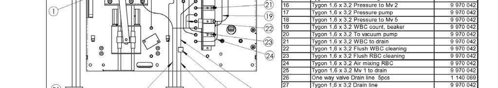
73 Chapter 11 Spare parts 11. Spareparts (v 01) 11.1 Sparepart drawings 1
74 Chapter 11 Spareparts 1

75 Chapter 11 Spareparts 2
76 Chapter 11 Spareparts 3

77 Chapter 11 Spareparts 4

78 Chapter 11 Spareparts 5


79 Chapter 11 Spareparts 6
MODEL 905V OPERATING INSTRUCTIONS
 MODEL 905V OPERATING INSTRUCTIONS Quantek Instruments 183 Magill Drive Grafton, MA 01519 Tel: (508) 839-3940 Fax: (508) 819-3444 Email: sales@quantekinstruments.com GENERAL DESCRIPTION These instructions
S 1125 HPLC Pump System
 Routine S 170 EXPERT HPLC HPLC System SYSTEMS 500 The Sykam ROUTINE HPLC System S 500 is intended for all routine analysis. The system configuration is highly variable and several upgrade options make
VECTRIX VX-2 SERVICE MANUAL. Version 1.0/May 2011 VECTRIX, LLC
 www.vectrix.com CONTENTS SECTION A: Tools 1 Tools Needed SECTION B: Mechanical Parts 1 Front Fairing 2 Front Console Cover 3 Speedometer Cover 4 Front Vertical Panel Cover-Lower 5 Front Vertical Panel
NEW HPLC - SYSTEM LINE
 NEW HPLC - SYSTEM LINE S c h a m b e c k S F D G m b H Drieschweg 13A D-53604 Bad Honnef/Germany Phone: +49 2224 9239-0 E-Mail: info@schambeck-sfd.com Internet: www.schambeck-sfd.com S 9425 HPLC solvent
Troubleshooting. CryoSmart 1 - CryoSmart 20
 Troubleshooting CryoSmart 1 - CryoSmart 20 ASTORI TECNICA di Astori Claudia & C. s.n.c. - Via Stelle, 11-25020 Poncarale (BS) - Italy Phone no.: +39 030 2540240 - Fax no.: +39 030 2640812 E-mail: info@astorioscar.com
BRAKE E
 8-1 GENERAL...8-2 SPECIFICATIONS...8-6 COMPONENTS...8-7 FRONT BRAKE...8-12 DISASSEMBLY INSPECTION REASSEMBLY (Pn1, Cu2 3 TON SERIES)...8-12 DISASSEMBLY INSPECTION REASSEMBLY (Pn2 3 TON SERIES)...8-17 BRAKE
EVAC Commercial Marine Equipment TOILET TECHNICAL DATA EVAC 90, STAINLESS STEEL, FLOOR MODEL, *SHOCK TESTED. Fresh water.
 16 Apr 2009 Doc. 1:141J TECHNICAL DATA 5327002 EVAC 90, STAINLESS STEEL, FLOOR MODEL, *SHOCK TESTED Fresh water connection Shut-off valve Strainer Vacuum breaker 390 Gasket Seat and cover Pneumatic push
PRO IV LIQUID DETERGENT & LIQUID RINSE DISPENSER INSTALLATION INSTRUCTIONS REVISION #5
 PRO IV LIQUID DETERGENT & LIQUID RINSE DISPENSER INSTALLATION INSTRUCTIONS REVISION #5 STEP #1. MOUNTING 1. Choose a location where the unit is visible to the machine operator. 2. Locate the unit out of
FRP SystemOne GELCOATER OPERATION MANUAL. MAGNUM VENUS PRODUCTS Operation Manual. Part No. M Revision
 1300-1-1 GELCOATER OPERATION MANUAL MAGNUM VENUS PRODUCTS Operation Manual Part No. M1300-1-1 Revision 04.26.01 Operation Manual Unit Information Unit # Type Of: Power Cylinder Metering Pump Gun Fluid
Autoplex Specifications
 Autoplex Specifications Autoplex G1 w/heating coil Stainless steel tip holds up to 150µl of liquid Probe tubing holds up to 3.18ml of liquid (length=88in, diameter=0.673mm/0.053in, 36.1µl/inch-high surface
GM 3000 AIRLESS PAINT SPRAYERS Drive Housing Replacement Kit Pinion Housing Replacement Kit
 INSTRUCTIONS 08660 INSTRUCTIONS This manual contains important warnings and information. READ AND KEEP FOR REFERENCE. Rev. B GM 000 AIRLESS PAINT SPRAYERS Drive Housing Replacement Kit 869 Pinion Housing
SIL. Part Number: RAN711A. ABX SPS / ABX SPS Evolution / ABX SPS Evolution wave 5 3 month periodical maintenance kit modification
 Tn SIL Part Number: RAN711A ABX SPS / ABX SPS Evolution / ABX SPS Evolution wave 5 3 month periodical maintenance kit modification QUAL-QA-TEMP-0220_rev15 Date: 25/10/13 ECR: 5308 3 month periodical maintenance
INSTALLATION INSTRUCTIONS FOR THE TRUCK MOUNTED VIPER ADDITIVE INJECTION SYSTEM GTP-8776C
 INSTALLATION INSTRUCTIONS FOR THE TRUCK MOUNTED VIPER ADDITIVE INJECTION SYSTEM GTP-8776C This additive injection system was designed to be used with five gallon jug of additive. The system is supplied
TECHNICAL INFORMATION
 TECHNICAL INFORMATION PRODUCT P 1 / 15 Model No. Description HR2455 Rotary Hammer 24mm (15/16") L W CONCEPT AND MAIN APPLICATIONS Model HR2455 has been developed as a sister tool to Model HR2450, the Makita
Product Guide: Series III Pump Control Board Set (RoHS)
") revised 04/08/10 Description: The Series III Pump Control Board Set provides motor drive and pump control for a wide assortment of pumps from Scientific Systems, Inc. The assembly consists of two circuit
revised 04/08/10 Description: The Series III Pump Control Board Set provides motor drive and pump control for a wide assortment of pumps from Scientific Systems, Inc. The assembly consists of two circuit
To avoid a short cut please file off the right half of the Y-hole flange.
 Fitting instructions for automatic alternator controller for Moto Guzzi with Bosch alternator 1. alternator modification - 2. Fitting - 3. adjustment (ignition only) First remove the connector block of
SofTouch Electronic Precision Pipette Instruction Manual
 SofTouch Electronic Precision Pipette Instruction Manual CONTENTS 1.HAMILTON SOFTOUCH ELECTRONIC PIPETTE... 2 1.1. SofTouch Single Channel Electronic Pipettes... 2 1.2. SofTouch Multi-Channel Electronic
INSTRUCTION MANUAL HI 921 AUTOSAMPLER
 HI 921 AUTOSAMPLER Revision 1.0 www.hannainst.com 1 2 Dear customer, Congratulations on choosing a Hanna Instruments product. This guide has been written for the HI 921 Autosampler. Please read this Quick
High Pressure Gradient System. User Manual. Version 1.0 ( )
") S 9432 HPLC Pump System High Pressure Gradient System User Manual Version 1.0 (2014-05-26) 2 Table of Contents Contents 1. Introduction 5 1.1 How to Use this Manual 5 1.1.1 Symbols 5 1.2 Safety Information
S 9432 HPLC Pump System High Pressure Gradient System User Manual Version 1.0 (2014-05-26) 2 Table of Contents Contents 1. Introduction 5 1.1 How to Use this Manual 5 1.1.1 Symbols 5 1.2 Safety Information
Z TECHNICAL INSTRUCTIONS
 ÍNDICE: Z40 2.0 TECHNICAL INSTRUCTIONS 1.- Error list 2.- Replace the control board 3.- Opening the machine 4.- Replace the power board 5.- Dismantling motor and gear box 6.- Assembly of gear box 7.- Pushing
Atomic Absorption Spectroscopy
 Atomic Absorption Spectroscopy Atomic absorption spectroscopy (AAS) is a widely used technique for determining a large number of metals. In the most common implementation of AAS, a liquid sample containing
COULTER MicroDiff. Field Service Technical Manual
 COULTER MicroDiff Field Service Technical Manual CC PN 4237161B (April 1993) Coulter Corporation Miami, FL 33196-2500 TM Coulter Corporation makes no representation that, upon furnishing this service manual,
Quick user guide for the DM dispenser
 Quick user guide for the DM dispenser READ FIRST! Use the shortest/thickest USB cable possible, if the screen dims too much during operation (to the point where it s hard to read the text) your cable or
Heavy Duty Sprayer Owners Manual Model MS-O
 Heavy Duty Sprayer Owners Manual Model MS-O Table of Contents Warranty 4 Warning 5 Assembly and Preparation 6 Operation 7 Cleaning and Storage 7 Standard Spray Gun & Parts List 8 Trigger Style Spray Gun
200 Series Flow Meters
 Proteus Industries Inc. 200 Series Flow Meters Technical Reference Manual Can we Improve? Tell our President! Can we improve our product, our support or this manual? We are committed to continuous improvement
Cateye Ergometer. Belt Drive, Automatic Type. Service Manual. Model EC-1200/EC-1600/EC-3600/EC-3700/EC-C400/EC-C400R Ver.
 Cateye Ergometer Belt Drive, Automatic Type Model ///// Service Manual 9.1.2002 Ver.01 INDEX INTRODUCTION How to Use This Service Manual Name of Parts 1. Upright Type (w/o Flywheel) ---------------------------------------------------------
Operation Manual BOTTLE TOP DISPENSER
 Operation Manual BOTTLE TOP DISPENSER TABLE OF CONTENTS Page No. Intended Use Of The Instrument 1 Safety Instructions 1 Functions and Limitations of Use 2 Operating Exclusions 3 Storage Conditions 3 Chemical
INSTALLATION INSTRUCTIONS 464, 424 & 324 POST-MIX VALVES
 INSTALLATION INSTRUCTIONS 464, 424 & 324 POST-MIX VALVES The Flomatic valves are available in manual, electric, portion control and automatic fill models. All Flomatic valves share the same mounting and
INDEX D1776 DISHWASHER (DW953)
") 1 INDEX D1776 DISHWASHER (DW953) PROGRAMS 2 ELECTRICAL FUNCTIONS 5 PART NUMBER SUFFIX DEFINITIONS 7 SPARE PARTS LISTS Casing and related parts 8 Container and related parts 10 Door 12 Control Panel 14
1 INDEX D1776 DISHWASHER (DW953) PROGRAMS 2 ELECTRICAL FUNCTIONS 5 PART NUMBER SUFFIX DEFINITIONS 7 SPARE PARTS LISTS Casing and related parts 8 Container and related parts 10 Door 12 Control Panel 14
DENISON HYDRAULICS Jupiter 500 Driver Card Series S
 Back to Content DENISON HYDRAULICS Jupiter 500 Driver Card Series S20-11712-0 Publ. 9-AM681 E-Mail: denison@denisonhydraulics.com Internet: http://www.denisonhydraulics.com SYSTEM FEATURES SYSTEM FEATURES
Cybex Arc Trainer Owner s & Service Manual. 7 - Service
 7 - Service Table of Contents......... iii Warnings/Cautions All warnings and cautions listed in this chapter are as follows:! WARNING: All maintenance activities shall be performed by qualified personnel.
EC 200 EC 300 GE 360 GE 400 GE 600 L-S BM
 DIESEL SPACE HEATER - SERVICE MANUAL INDEX 1. CONTROLS AND COMPONENTS 2. FLAME CONTROL CYCLES 3. MAINTENANCE SCHEDULE 4. REPAIR PROCEDURES 1. FAN MOTOR ASSEMBLY 2. FUEL FILTER ASSEMBLY 3. FUEL PUMP ASSEMBLY
FULL AUTOMATIC ASPHALTENE ANALYZER APD-500A USER S GUIDE
 FULL AUTOMATIC ASPHALTENE ANALYZER APD-500A USER S GUIDE Please read this manual carefully to ensure correct use of this analyzer before you start to use it. COSMO TRADE & SERVICE CO., LTD. TABLE OF CONTENTS
Sliding Gate Operator User's Manual
 Sliding Gate Operator User's Manual PY800AC/PY00AC. Products introduction Please read the instructions carefully before proceeding. MCU is supplied to control the gate operator. Keypad / single button
User Manual dpette+ Electronic Pipette 2016-ver.1
 User Manual dpette+ Electronic Pipette 2016-ver.1 CONTENTS 1. Product Overview...- 1-2. Parts Description...- 3-3. Display... - 5-4. Operation...- 6-5. dpette+ setup... - 14-6. Storage... - 18-7. Care
JADE Bottle Top Dispenser
 Accrediting Certifying Bodies S C B A (E) ASCB(E) UK ISO 13485 JADE Bottle Top Dispenser Re-Circulation Valve Operation Manual TABLE OF CONTENTS Page No. Intended Use Of The Instrument 1 Safety Instruction
ChemWell Replacement Parts & Accessories
 ChemWell Replacement Parts & Accessories Description ChemWell Duffle Bag ChemWell Mouse Pad Photometer Calibration Kit Reagent Cooling Accessory Ordered with New ChemWell - RCA (230V) Reagent Cooling Accessory
for filling and bleeding hydraulic disk brake systems Instruction
 Seite 1 von 6 Instruction All processes described in this instruction are applicable for brake fluid DOT4 and hydraulic fluid based on mineral oil. Never the less the fluids must never be mixed up, otherwise
Perfmaster Air V3. Serial Number. Date
 Perfmaster Air V3 12-2015 Serial Number Date TABLE OF CONTENTS SPECIFICATIONS.3 SAFETY PROCEDURES/CARE & MAINTENANCE..4 COMPONENT IDENTIFICATION 5 DELIVERY TRAY ASSEMBLY.6 PAPER STOP ASSEMBLIES..7 MACHINE
AUTOMATIC AMINO ACID ANALYSER AAA 400
 INGOS Ltd. AUTOMATIC AMINO ACID ANALYSER AAA 400 User manual PRAGUE Apr 11 006 Producer : Laboratory Instruments division of INGOS Ltd. Development : PiKRON Ltd. Chemical system : V. Havlíček - ZMBD chemik
Torqueflite Manual/Automatic Valve Body
 TCI 122400 Torqueflite Manual/Automatic Valve Body This valve body can be installed in a few hours by carefully following directions. Read all instructions first to familiarize yourself with the parts
economics and performance Spark Holland introduces OPTIMAS The optimum balance of BETTER SAMPLE CARE
 BETTER SAMPLE CARE Spark Holland introduces OPTIMAS The optimum balance of economics and performance Spark Holland introduces OPTIMAS The optimum balance of economics and performance OPTIMAS The optimum
Start Up & Troubleshooting Manual. Resfab Equipment Inc. St Jean Sur Richelieu Website: resfab.com
 Start Up & Troubleshooting Manual Resfab Equipment Inc. 725 Rossiter St Jean Sur Richelieu 1 450 359 0800 Website: resfab.com Yogurt Blender Service Manual Page SECTION 1: Start Up and Repair... 3 thru
TECHNICAL INFORMATION Model No. Description
 TECHNICAL INFORMATION Model No. Description CONCEPT AND MAIN APPLICATIONS Specification HR2450, HR2451, HR2452 24mm (15/16 " ) Rotary Hammer The above models are the advanced version of MAKITA's famous
Digital Burette. Assembly and operating instructions. For capacities of 30ml & 50ml
 Digital Burette Assembly and operating instructions For capacities of 30ml & 50ml General Safety Instructions Careful safety precautions must apply when dispensing corrosive, radioactive or hazardous chemicals.
Troubleshooting. This section outlines procedures for troubleshooting problems with the operation of the system:
 Troubleshooting This section outlines procedures for troubleshooting problems with the operation of the system: 4.1 System Error Messages... 4-2 4.2 Prep Station Troubleshooting... 4-6 4.2.1 Adapter Not
VOLTAGE CONNECTOR CORCOM S VOLTAGE SELECTING AND FUSED CONNECTOR
 IMCO.US MADE IN USA VOLTAGE CONNECTOR CORCOM S VOLTAGE SELECTING AND FUSED CONNECTOR Developed for the manufacturer who markets his products worldwide, the Voltage Connector eliminates the need for internal
Miniature Inert PTFE Isolation Valves. Physical Properties Electrical Performance Characteristics
 2-Way and 3-Way Solenoid Valves Typical Applications Reagent Control Solvent Management Aggressive Liquid Control Product Specifications Valve Type: Diaphragm Isolation Valve Valve Configuration: 3-Way
MAINTENANCE MANUAL DI 16
 MAINTENANCE MANUAL DI 16 0.2-1.6% Press Ctrl + L for full screen 1 STANDARD INSTALLATION Inlet Outlet Optional accessories: Pressure regulator Solenoid valves Water meter Flow restrictor 200 Mesh/ 80 micron
Service Handbook High-Pressure Washer Pump
 Service Handbook High-Pressure Washer Pump 9.120-014.0 2 A. Water Inlet Filter C. Nozzle Insert 1. Remove filter with a screwdriver. 2. Clean filter with warm water and mild soap. 3. Reinstall filter.
Spray Height Controller
 Spray Height Controller UC5 SERVICE MANUAL 2012 Printed in Canada Copyright 2012 by NORAC Systems International Inc. Reorder P/N: UC5 SERVICE MANUAL 2012 Rev B NOTICE: NORAC Systems International Inc.
Sliding Gate Operator User's Manual
 Sliding Gate Operator User's Manual SL600AC. Products introduction Please read the instructions carefully before proceeding. MCU is supplied to control the gate operator. Keypad / single button interface.
INSTRUCTION MANUAL. Mi490 Peroxide value. Milwaukee Lab Photometer. Test Equipment Depot Washington Street Melrose, MA 02176
 Test Equipment Depot - 800.517.8431-99 Washington Street Melrose, MA 02176 INSTRUCTION MANUAL Milwaukee Lab Photometer Mi490 Peroxide value TestEquipmentDepot.com 1 Instruction Manual Mi490 PEROXIDE VALUE
Never charge the batteries with a charger other than that supplied by the manufacturer.
 INTRODUCTION The Diamond SeroLogic portable pipette controller is a rechargeable electronic pipetting aid designed for use with glass or plastic serological pipettes in the 0.1 to 100mL volume range. The
by Instrumentation Pumps 1 / 8
 600-000 by Instrumentation Pumps 1 / 8 1. Safety Requirements... 3 2. Pump Mounting... 3 3. General Set Up... 4 3.1. Quick Start... 4 3.2. Speed... 5 3.3. Fluidics... 5 4. Maintenance... 5 4.1. Idle Position...
MAINTENANCE CHECKLIST
 Maintenance Schedule Overview The DWX-4W must be maintained on a consistent basis to perform optimally. After installation, there are daily, weekly, and monthly maintenance schedules to keep for various
BE 20 IMI Cornelius Orange Juice Dispenser Model Quest Elite QLT 2000
 BEVERAGE EQUIPMENT BE 20 IMI Cornelius Orange Juice Dispenser Model Quest Elite QLT 2000 Daily maintenance tasks BE 20 D1 Flush orange juice system Weekly maintenance tasks BE 20 W1 Sanitize orange juice
Tools Needed for Mounting Cleá Filling Station
 ALWAYS OBSERVE PRODUCT SAFETY AND HANDLING INSTRUCTIONS. ALWAYS DIRECT DISCHARGE AWAY FROM YOU or other persons. ALWAYS DISPENSE CLEANERS AND CHEMICALS AS DIRECTED ON THE LABEL. ALWAYS DISPENSE INTO APPROVED
Micro 215 Liquid Handler User's Guide
 Micro 215 Liquid Handler User's Guide LT2537/ 2000 Gilson, Inc. All rights reserved April 2000 Table of Contents 1 Introduction 2 Installation Safety Precautions... 1-2 Unpacking... 1-3 Standard Equipment...
SERVICE MANUAL ULTIMATE 200
 SERVICE MANUAL ULTIMATE 200 This manual is for: 20 200-120 Ultimate 200 std. 120V 60 Hz 20 200-240 Ultimate 200 std. 240V 50 Hz 20 201-120 Ultimate 200 DMX 120V 60 Hz 20 201-240 Ultimate 200 DMX 240V 50
Operation and Maintenance Manual
 BM / BMA Hydrometers ½ Operation and Maintenance Manual i This manual is intended for use by the users of this equipment. The information contained herein is the property of the Arad Ltd. Dalia and may
SD Bendix E-10PR Retarder Control Brake Valve DESCRIPTION. OPERATION - Refer to Figure 2
 SD-03-832 Bendix E-10PR Retarder Control Brake Valve MOUNTING PLATE SUPPLY 4 PORTS ELECTRICAL AUXILIARY DESCRIPTION TREADLE RETARDER CONTROL SECTION EXHAUST DELIVERY 4 PORTS FIGURE 1 - E-10PR RETARDER
Operating manual. ph / mv controller type M8832N
 Mostec AG Mess- und Regeltechnik Lausenerstr. 13A CH-4410 Liestal / Switzerland Tel. 061/921 40 90 Fax 061/921 40 83 Operating manual ph / mv controller type M8832N Description of the «leak proof housing»
1260 Infinity II Degasser User Manual. 5 Maintenance
 1260 Infinity II Degasser User Manual 5 Maintenance Warnings and Cautions 40 Simple Repairs - Maintenance 42 Clean the Instrument 43 Assemble the Main Cover 44 Check and Change the Power Fuses 45 This
5000TOC Sensor Service Manual
 Part No. 84449 5000TOC Sensor Service Manual This document contains proprietary information, which is protected by copyright. All rights are reserved. No part of this document may be photocopied (other
Dilutor Module for TriPlus RSH
 Thermo Scientific Dilutor Module for TriPlus RSH Instruction Manual Additional section of the TriPlus RSH User Guide and Hardware Manual 31709661 Revision A December 2015 2015 Thermo Fisher Scientific
Marking Systems. Paint Spray Systems Marking Blocks Paints & Inks
 Marking Systems Paint Spray Systems Marking Blocks Paints & Inks Various Applications Usage and Setup Flexibility Precise edging and maximum reproducibility with virtually zero overspray. Automated Dot
PROBLEM SOLVING GUIDE ELMECO SLUSH MACHINE MODEL FCM
 A01 INSTRUCTIONS ON HOW TO READ REFERENCES...2 A10 FEATURES AND TECHNICAL SPECIFICATIONS...3 A15 RECOMMENDED PREVENTIVE MAINTENANCE SPARE PARTS KIT...3 A20 IMPORTANT INFORMATION ON FUNCTIONALITY OF THE
Heated Perfusion Cube
 Heated Perfusion Cube HPC-2 / HPC-2A Instruction Manual ver. Feb.2011 ALA Scientific Instruments Inc. 60 Marine Street Farmingdale, NY 11735 Tel. # 631.393.6401 FAX: # 631.393.6407 E-mail: support@alascience.com
Fluid Waste Handling System Mechanical
 Fluid Waste Handling System Fluid Waste collected through Manifold Drain Valve Fluid Waste System Theory of Operation At the Docking Station, fluid waste is removed from the Rover s s and discarded into
Micro-Injection System
 QUIK-- Micro-Injection System Table of Contents Part 1: Getting Started & Using your QUIK-jet Air Parts of the QUIK-jet Air Device...2 Parts of the QUIK-jet Air Kit...3 Air Tank Assembly...4 Connecting
100 Series Flow Switches Technical Reference Manual
 Proteus Industries Inc. 100 Series Flow Switches Technical Reference Manual Can we Improve? Tell our President! Can we improve our product, our support or this manual? We are committed to continuous improvement
Physiological Calibration Standard II Calibration standard physiological fluid CALIBRATION STANDARD PROTEIN
 80-6000-32 Physiological Calibration Standard II 80-2037-62 Calibration standard physiological fluid 80-2037-61 CALIBRATION STANDARD PROTEIN HYDROLYSATE 80-2104-53 1/8" FLANGELESS FITTING (PK 5) 80-2108-41
10 Maintenance. Agilent Technologies. This chapter describes the maintenance of the module Infinity Binary Pump User Manual
 1260 Infinity Binary Pump User Manual 10 Maintenance Introduction to Maintenance and Repair 148 Warnings and Cautions 149 Cleaning the Module 151 Overview of Maintenance and Simple Repairs 152 Maintenance
TILLOTSON LTD., CLASH INDUSTRIAL ESTATE, TRALEE, CO. KERRY, IRELAND PHONE: FAX:
 TILLOTSON LTD., CLASH INDUSTRIAL ESTATE, TRALEE, CO. KERRY, IRELAND PHONE: +353 66 7121911 FAX: +353 66 7124503 e-mail: sales@tillotson.ie HU SERIES SERVICE MANUAL INTRODUCTION To keep apace of new market
HPLC System S 600 Series
 HPLC System S 600 Series The Sykam HPLC System S 600 Series is intended for the ambitious analyst. The system configuration is highly variable and several upgrade options make this system suitable for
DENISON HYDRAULICS open loop pump controls series P140 A-mod, P260 B-mod service information
 DENISON HYDRAULICS open loop pump controls series P10 A-mod, P260 B-mod service information Publ. S1-AM02-A replaces S1-AM02 01-97 CONTENTS typical characteristics-------------------------------------------------------------------------------
General Purpose Flasher Circuit
 General Purpose Flasher Circuit By David King Background Flashing lights can be found in many locations in our neighbourhoods, from the flashing red light over a stop sign, a yellow warning light located
INSTALLATION, OPERATION AND MAINTENANCE Threaded and Wafer Style Flowmeters
 INSTALLATION, OPERATION AND MAINTENANCE Threaded and Wafer Style Flowmeters Table of Contents Page 1. Principle of Operation...2 2. Installation Planning......2 3. Installation...3 3.1 Safety Considerations...
OPTIONS AUTOMATIC LUBRICATION SYSTEM
 OPTIONS AUTOMATIC LUBRICATION SYSTEM The central lubrication of the axes modules consists of a small lubricant dispenser with progressive distributor with several exits. It is responsible for the automatic
BRAKE SYSTEM Return To Main Table of Contents
 BRAKE SYSTEM Return To Main Table of Contents GENERAL... 2 BRAKE PEDAL... 10 MASTER CYLINDER... 13 BRAKE BOOSTER... 16 BRAKE LINE... 18 PROPORTIONING VALVE... 19 FRONT DISC BRAKE... 20 REAR DRUM BRAKE...
INSTALLATION GUIDE Ultrasonic Sensors Series UX micro
 INSTALLATION GUIDE Ultrasonic Sensors Series UX micro For further information please see the data sheet at www.waycon.biz/products/ultrasonic-sensors/ FIRST STEPS WayCon Positionsmesstechnik GmbH would
TROUBLESHOOTING TP. Index
 TROUBLESHOOTING TP Index E1 POWER CUT DETECTED... 2 E2 LOCK ERROR... 3 E3 DRAINAGE FAILURE / WATER IN TUB... 6 E4 MAXIMUM WATER LEVEL REACHED... 6 E5 FAULT WATER INLET... 6 E6 HEATING FAULT... 6 E7 MAXIMUM
Operator s Manual Version 1.21 TR-200. Peristaltic Pump. Durham Geo Slope Indicator 2175 West Park Court Stone Mountain, GA USA
 Peristaltic Pump TR-200 Operator s Manual Version 1.21 Durham Geo Slope Indicator 2175 West Park Court Stone Mountain, GA 30087 USA Phone: 800-837-0864 or +1.770.465.7557 Fax: 770.465.7447 e-mail: solutions@durhamgeo.com
Instruction Manual Bedienungsanleitung Mode d emploi Manual de Instrucciones Instruzioni d impiego BIOH T
 TM eline Instruction Manual Bedienungsanleitung Mode d emploi Manual de Instrucciones Instruzioni d impiego BIOH T BIOH T TM eline Instruction Manual...1 Bedienungsanleitung...37 Mode d emploi...73 Manual
Torqueflite Trans-Scat Kit
 TCI 220000 Torqueflite Trans-Scat Kit This kit can be installed in a few hours by carefully following directions. Read all instructions first to familiarize yourself with the parts and procedures. Work
HGM-MZ Multi-Zone Monitor Annual Maintenance And Troubleshooting Guide
 HGM-MZ Multi-Zone Monitor Annual Maintenance And Troubleshooting Guide Service, Testing and Maintenance procedures BACHARACH Inc. HGM-MZ Routine Annual Maintenance And Operating Parameter Verification
Agilent G5632 Valve Kit Instructions
 Agilent G5632 Valve Kit Instructions Agilent G5632 Valve Kit Instructions Contents Typical Applications 2 Alternating Column Regeneration (2 position/10 port valves only) 2 Dual column selection 3 Sample
INDEX TECHNICAL SERVICE BULLETIN
 CELL-DYN 1300/1400 (91) Index Page 1 ABBOTT ADD INDEX TECHNICAL SERVICE BULLETIN PRODUCT: CELL-DYN 1300/1400 (91) DATE: 08-APR-98 TSB # IMPLEMENTATION SUBJECT EFFECTIVITY DATE 91-020A O - See Attached
3.1 DISPENSER BLACK SHADOW SERIES. Tools Needed for Mounting SCS Dispenser Hammer
 SCS 2 BLACK SHADOW SERIES 3.1 DISPENSER ALWAYS OBSERVE PRODUCT SAFETY AND HANDLING INSTRUCTIONS. ALWAYS DIRECT DISCHARGE AWAY FROM YOU or other persons. ALWAYS DISPENSE CLEANERS AND CHEMICALS AS DIRECTED
Statim G4 Error Codes
 Statim G4 Error Codes All leaks should be corrected before proceeding with troubleshooting Cycle Fault #1 The cassette temperature failed to reach 95 C within a time-out period. 1. An extremely large steam
SE-3SCR-LM MANUAL MOTOR LOAD MANAGER
 3714 Kinnear Place Saskatoon, SK Canada S7P 0A6 Ph: (306) 373-5505 Fx: (306) 374-2245 www.littelfuse.com/relayscontrols SE-3SCR-LM MANUAL MOTOR LOAD MANAGER MARCH 5, 2013 REVISION 4 MOTOR LOAD MANAGER
AQUASTAR C6. (Comfort 6000) Next Generation Auto Backwash Valve System. (selectable time-pressure or remote cycle start)
 Next Generation Auto Backwash Valve System. (selectable time-pressure or remote cycle start)") AQUASTAR C6 (Comfort 6000) Next Generation Auto Backwash Valve System (selectable time-pressure or remote cycle start) SIDE MOUNTED AND TOP MOUNTED VALVES WITH QUICK INSTALL ELECTRIC ACTUATORS FOR PIPE
AQUASTAR C6 (Comfort 6000) Next Generation Auto Backwash Valve System (selectable time-pressure or remote cycle start) SIDE MOUNTED AND TOP MOUNTED VALVES WITH QUICK INSTALL ELECTRIC ACTUATORS FOR PIPE
HPLC Model 210D. UV detector lamp switch. Rheodyne 7725i injection valve. Prime/purge valve. Column. compartment. thumbscrews. Storage.
 1. Overview The front panel houses the UV detector lamp switch, Rheodyne injection valve, prime/purge valve, pressure gauge, and the storage compartment. In the storage compartment are the LED display
Agilent InfinityLab Quick Change Valve G4237A
 Agilent InfinityLab Quick Change Valve G4237A Instructions Agilent G4237A Valve Kit Instructions This technical note describes the installation and application of the Agilent InfinityLab Quick Change 4
Motor Valve MV-7/IMV-7
 Motor Valve MV-7/IMV-7 INSTRUCTIONS 1. Introduction Motor Valves MV-7/IMV-7 are a 3-position, 7-port motorized valves designed to he used as automatic sample injection valves or system valves. The valves
A-320 Balanced 1st Stage
 Technical Manual A-320 Balanced 1st Stage A Manual for Repair and Maintenance Technicians View: Select Full Screen mode to use page arrows. FEATURES Extra durable satin chrome plated brass body. Fully
35 35A 50 50A 1 Single phase. Solid state power controller
 Single Phase, Power Controller Single Phase, Power Controller Features Various and simple input specification DC4-2mA, 1-5VDC, External 24VDC External adjuster (1kΩ) External contact (ON/OFF) Various function
Cold Vapor Mercury Apparatus* Purpose Figure 1 Cold Vapor Mercury Apparatus Assembly Overview
 26744-88 Cold Vapor Mercury Apparatus* Purpose This instruction sheet shows how to assemble the apparatus set (26744-00) necessary for performing the Hach Cold Vapor Mercury Method (method 10065). Figure
5-2 FUEL SYSTEM AND THROTTLE BODY FUEL SYSTEM FUEL DELIVERY SYSTEM The fuel delivery system consists of the fuel tank, fuel pump, fuel filters, fuel f
 FUEL SYSTEM AND THROTTLE BODY 5-1 FUEL SYSTEM AND THROTTLE BODY I CONTENTS FUEL SYSTEM 5-2 FUEL DELIVERY SYSTEM 5-2 FUEL PUMP 5-3 FUEL PRESSURE REGULATOR 5-4 FUEL INJECTOR 5-4 FUEL PUMP CONTROL SYSTEM