BITZER Capacity Controller for CSH Compressors Temperature Sensor
|
|
|
- Andra Hubbard
- 5 years ago
- Views:
Transcription


1
2 only. The Temperature Controller has been obsoleted. The below data is for informational purposes only BITZER Capacity Controller for CSH Compressors Temperature Sensor The BITZER CSH Capacity Controller (PN# ) is designed to control the loading and unloading of the CSH series compressors based on temperature. This controller does not have the capability of starting or stopping the compressor nor does it have the ability to operate as a system safety device. These functions must be controlled by other devices in the system. Mounting the Controller: Cut or punch a 3.8 x 1.9 rectangular hole in the door of the enclosure or flat panel. Install the unit into the panel by sliding it back first into the opening and pressing firmly against the surface until the mounting clips capture the device. Sensor Types Two types of temperature sensors are available for this controller. Sealed End (bulb type) sensor that can be mounted to the exterior of a pipe or mounted on a rod and centered in an air stream (PN# ) (See Figure 5). To line mount this sensor, first the surface of the pipe should be cleaned to a bright metal appearance. Heat transfer paste should be used to assure proper operation. The bulb can be held in place with the use of a pipe clamp. 1/4 NPT sensor that can be inserted into the process stream (PN# ) (See Figure 6). These sensors are connected to the controller by a three prong plug that is located on the back of the controller. Power Wiring The Controller can be utilized with either 120 or 240 VAC control voltage power. 120 Volt Power: the hot lead should be connected to the 120/240V terminal and the neutral lead should be connected to the Neutral terminal. A jumper must be installed across the two terminals labeled Install Jumper for 120V. 240 Volt Power: the hot lead should be connected to the 120/240V terminal and the neutral lead Capacity Control The controller has Dual Capacity Control Functions. It can operate the compressor either by Infinite Capacity Control or by 4-Step Capacity Control by changing the placement of a jumper on the back of the controller (See Figure 1 through Figure 4). Infinite Capacity Control The Jumper must be installed on the center and left prongs located under Step and Infinite. Solenoid coils must be installed on CR3 and CR4. The controller will cycle these coils to maintain the set point temperature within the differential temperature programmed. The compressor capacity will be varied from 25 to 100% of its rated capacity. 4-Step Capacity Control The jumper must be installed on the center and right prongs located under step and infinite. Solenoid coils must be installed on CR1, CR2, CR3 and CR4. The controller will cycle these coils too vary the compressors capacity in 4 discrete steps of 25, 50, 75 and 100% of its rated capacity. For a detailed description on the capacity control of the CSH series compressors, refer to the Application Manual SH Set Point Temperature: To enter the set point temperature press and hold the Set Point Temp button and press the up and/or down buttons until the desired value is played. Differential Temperature: To set the differential temperature, press and hold the Diff Temp button and press the up and/or down buttons until the desired value is displayed. Temperature Probe Calibration: If calibration of the temp probe is necessary, change the set point temperature until it matches the Actual temperature reading. Press and hold the set Point Temp and Diff Temp buttons at the same time and hold for 10 seconds. The display will flash indicating the calibration is complete. Return the set point temperature to the desired value. should be connected to the Neutral terminal. No jumper should be installed across the two terminals labeled Install Jumper for 120V.
3
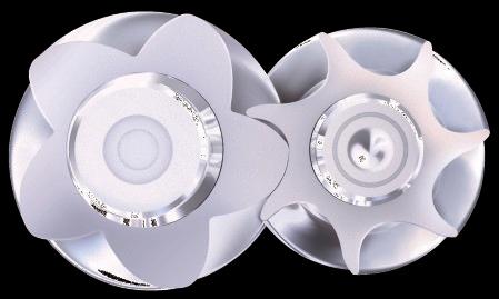
4 Figure 5 BITZER PN# Figure 6 BITZER PN#
5
6 Specifications for the BITZER Screw Temperature Capacity Controller SCC-10A (Obsolete PN# ) and Sensors (PN# (Bulb Type) or PN# (NPT)). Both components were available in kit form (Obsolete PN# (Bulb Type Sensor) or Obsolete PN# (NPT Sensor))
7 BITZER Capacity Controller for CSH Compressors Pressure Sensor The BITZER Screw Pressure Capacity Controller SCC-10P (PN# ) is designed to control the loading and unloading of the CSH series compressors based on pressure. This controller does not have the capability of starting or stopping the compressor, nor does it have the ability to operate as a system safety device. These functions must be controlled by other devices in the system. Mounting the Controller Cut or punch a 3.8 X 1.9 rectangular hole in the door of the enclosure or flat panel. Install the unit into the panel by sliding it back first into the opening and pressing firmly against the surface until the mounting clips capture the device. Sensor Types One type of pressure sensor is available for this controller. 1/4 NPT sensor that can be inserted into the process stream (PN# ) (See Figure 7). This sensor is connected to the controller by a three prong plug that is located on the back of the controller. Power Wiring The controller can be utilized with either 120 or 240 VAC control voltage power. 120 Volt power, the hot lead should be connected to the 120/240V terminal and the neutral lead should be connected to the Neutral terminal. A jumper must be installed across the two terminals labeled Install Jumper for 120V. 240 Volt power, the hot lead should be connected to the 120/240V terminal and the neutral lead should be connected to the Neutral terminal. No jumper should be installed across the two terminals labeled Install Jumper for 120V. Capacity Control The controller has dual capacity control functions. It can operate the compressor either by Infinite Capacity Control or by 4-Step Capacity Control by changing the placement of a jumper on the back of the controller (See Figure 1 through Figure 4). Infinite Capacity Control The jumper must be installed on the center and left prongs located under Step and Infinite. Solenoid coils must be installed on CR3 and CR4. The controller will cycle these coils to maintain the set point pressure within the differential pressure programmed. The compressor capacity will be varied from 25 to 100% of its rated capacity. 4-Step Capacity Control The jumper must be installed on the center and right prongs located under Step and Infinite. Solenoid coils must be installed on CR1, CR2, CR3 and CR4. The controller will cycle these coils to vary the compressor s capacity in 4 discrete steps, 25, 50, 75 and 100% of its rated capacity. For a detailed description on the capacity control of the Compact series compressors, refer to the Application Manual SH Set Point Pressure To enter the set point pressure, press and hold the Set Point Press button and press the up and down buttons until the desired value is displayed. Differential Pressure To set the differential pressure, press and hold the Diff Press button and press the up and down buttons until the desired value is displayed. Pressure Probe Calibration If calibration of the pressure probe is necessary, change the set point pressure until it matches the Actual temperature reading. Press and hold the Set Point Press and Diff Press buttons at the same time and hold for 10 seconds, the display will flash indicating the calibration is complete. Return the set point temperature to the desired value.


8 Pressure Transducer Figure 7 BITZER PN#
9
10 Specifications for the BITZER Screw Pressure Capacity Controller SCC-10P (PN# ) and Sensor (PN# ). Both components are available in kit form (PN# ). Input Voltage 120V Terminal 240V Terminal Frequency Range Output Rating Temperature Range: Operational Storage Pressure Sensing Accuracy Humidity Tolerance Operating Parameters: Set Point Pressure Range Differential Pressure Range CR1 Turn-On Level CR2 Turn-On Level CR3 Turn-On Level CR4 Turn-On Level 90 to 132 VAC 180 to 264 VAC 50 to 60 Hz 1 Amp at 120/240 VAC 0 0 to F (calibrated) to F (un-calibrated) Plus/Minus 3 psi 0 to 97% (non-condensing) 18 to 110 Psia (3 to 96 Psig) 0.5 to 10 Psid Not Applicable for Infinite Capacity < or = Set Point, > Set Point Diff. Press for step capacity Not Applicable for Infinite Capacity < or = Set Point Diff. Press, > Set Point 2 x Diff. Press for step capacity < / = Set Point Diff. Press (Infinite Capacity) < / = Set Point 2 x Diff. Press (Step Control) > Set Point + Diff. Press (Infinite Capacity) Automatic upon application of power, (Step Capacity) until CR1, CR2 or CR3 energizes. Then CR4 operates with 1 second on and 10 seconds off intervals
11
BITZER Liquid Injection Guidelines for CSH Compressors
 BITZER Liquid Injection Guidelines for CSH Compressors Liquid Injection Additional cooling may be required during reduced capacity operation, high condensing and / or low evaporating temperatures. Direct
System 350 P352AB Electronic Pressure Control Series
 System 350 P352AB Electronic Pressure Control Series System 350 Product Guide 930 Basic Controls Section Product/Technical Bulletin P352AB Issue Date 0200 The P352AB controls are On/Off electronic pressure
Corsa Performance Marine Solenoid & Harness Testing Procedures
 Solenoids/Actuators Four-Wire Solenoid Testing Procedures (White Connector) 1. Disconnect solenoid from harness at quick disconnect and check terminals for corrosion. Terminal plugs should be locked in
INSTRUCTION MANUAL AUTO-PUMP 220/240 VAC MODEL #091-9B-220. INPUT :220/240 volt, 50/60 Hz, 1.9/2.2 AMPS OUTPUT: 100 PSI MAXIMUM 1 YEAR WARRANTY
 BOOK# 091-9B-220 4-18-2002 INSTRUCTION MANUAL AUTO-PUMP 220/240 VAC AIR COMPRESSOR SYSTEM MODEL #091-9B-220 INPUT :220/240 volt, 50/60 Hz, 1.9/2.2 AMPS OUTPUT: 100 PSI MAXIMUM 1 YEAR WARRANTY KUSSMAUL
Application Engineering
 Application Engineering February, 2009 Copeland Digital Compressor Controller Introduction The Digital Compressor Controller is the electronics interface between the Copeland Scroll Digital Compressor
Figure 1: WPR2 Dimensions and Hardware
 Installation and Operation Instructions WPR2 Series (Max. Line Pressure < 300 PSI) Wet to Wet Differential Pressure Ø0.200" 2.60" 4.47" 5.47" 5.28" 3.00" Precautions Figure 1: WPR2 Dimensions and Hardware
AUTO-PUMP 120 VAC AIR COMPRESSOR SYSTEM INSTRUCTION MANUAL. 170 Cherry Avenue West Sayville, NY
 INSTRUCTION MANUAL AUTO-PUMP 120 VAC AIR COMPRESSOR SYSTEM MODEL #: #:091-9B-1 091-9B-1 INPUT :120 volt, 50/60 Hz, 1.8 AMPS OUTPUT: 100 PSI MAXIMUM File: 091-9B-1_revA1_GEN3 Rev: A1 Revised By:PSS/JRN
Application Engineering
 Application Engineering March 2011 Copeland Digital Compressor Controller Introduction The Digital Compressor Controller is the electronics interface between the Copeland Scroll Digital compressor or the
BOILER BLOWDOWN CONDUCTIVITY CONTROLLER (CONTINUOUS METHOD)
") LAKEWOOD INSTRUMENTS MODEL 260 SERIES BOILER BLOWDOWN CONDUCTIVITY CONTROLLER (CONTINUOUS METHOD) INSTALLATION & OPERATION MANUAL SERIAL #: Lakewood Instruments 7838 North Faulkner Road, Milwaukee, WI
LAKEWOOD INSTRUMENTS MODEL 260 SERIES BOILER BLOWDOWN CONDUCTIVITY CONTROLLER (CONTINUOUS METHOD) INSTALLATION & OPERATION MANUAL SERIAL #: Lakewood Instruments 7838 North Faulkner Road, Milwaukee, WI
DMT PERFORMING UNDER PRESSURE DMT. Pressure Scanner Features. Applications. Description 1/7
 Features User Accessible Memory for Test Configuration Management ±0.05% FS System Accuracy EU Throughput Rates of 500 Hz Auto-Negotiating 10/100 BaseT Ethernet with TCP & UDP Protocol Pressure Ranges
6. Document tasks performed during visit and report any observations to the appropriate
 Chiller Annual Maintenance RFP Attachment B Services Required Tasking: Vibration Analysis 1. All work shall be performed in accordance with safety policies 2. Check with appropriate customer representative
SUSSMAN 'ES, HU and MBA' SERIES PARTS LIST EFFECTIVE: 7/24/2017
 EFFECTIVE: 7/24/2017 STEAM SAFETY VALVES 99136 100 PSIG 1/2" NPT (ES12 to ES72) 99137 100 PSIG 1" NPT (ES84 to ES180) 99132 15 PSIG 1/2" NPT (ES12 to ES48, HU40 to HU140) 99297V 15 PSIG 3/4" NPT (ES60
SSI Technologies MediaSensor
 SSI Technologies MediaSensor P51 Pressure Transducers Product Description SSI s line of bulk micro-machined, absolute and gage pressure transducers and transmitters for both harsh and benign media with
HS Refrigeration Screw Compressor Troubleshooting Guidelines. SG March 2014
 HS Refrigeration Screw Compressor Troubleshooting Guidelines SG-0003-01 March 2014 Refrigeration Screw Compressor Troubleshooting Guidelines SG-0003-01 March 2014 BITZER Screw Compressors CS High Temp
Operators Manual ECO-AIR-IVS Internal Valve Actuation System
 2534-A Shell Road Georgetown, TX 78628 www.parafour.com 512-626-4099 Operators Manual ECO-AIR-IVS Internal Valve Actuation System Ver 1.0 Warnings:!! This device is electrically operated and should only
Bitzer CSH Series To Fusheng
 Bitzer CSH Series To Fusheng Competitive Replacement Guideline M-BSR-EC3-201604 FUSHENG Screw Compressor BSR Series The intention of this document is to serve as general guidelines. The information contained
PS1 Single High and Low Pressure & PS2 Dual Pressure Refrigeration Controls. Instruction Sheet PA October 2007
 Instruction Sheet PA-00281 October 2007 PS1 Single High and Low Pressure & PS2 Dual Pressure Refrigeration Controls PS1 Single High and Low Pressure & PS2 Dual Pressure Refrigeration Controls THE FLEXIBLE
MODEL 422 Submersible Pump Controller
 MODEL 422 Submersible Pump Controller Monitors True Motor Power (volts x current x power factor) Detects Motor Overload or Underload Operates on 120 or 240VAC, Single-phase or 3-phase Built-in Trip and
4 qwer 2/2. Pilot Operated General Service Solenoid Valves. Brass or Stainless Steel Bodies 3/8" to 2 1/2" NPT. Features. Construction.
 4 qwer Pilot Operated General Service Solenoid Valves Brass or Stainless Steel Bodies 3/8" to 2 1/2" NPT NC NO 2/2 SERIES Features Wide range of pressure ratings, sizes, and resilient materials provide
SECTION 3 BASIC AUTOMATIC CONTROLS UNIT 15 Troubleshooting Basic Controls
 SECTION 3 BASIC AUTOMATIC CONTROLS UNIT 15 Troubleshooting Basic Controls UNIT OBJECTIVES After studying this unit, the reader should be able to Describe and identify power- and non-power-consuming Describe
Technical Data Sheet FT & FIT-1003 SERIES AIR VOLUME/ VELOCITY TRANSDUCERS. Features DESCRIPTION
 Technical Data Sheet FT & FIT-1003 SERIES AIR VOLUME/ VELOCITY TRANSDUCERS DESCRIPTION FT & FIT-1003 Series transducers include Models FT-1003, FT-1003-ZV, FIT-1003-D, FIT-1003-DZV, FIT-1003-M, and FIT-1003-MZV.
DIN-Rail DC UPS. Powers Loads and Charges Back-Up Battery, Ideal for Automation and Wireless System Transmitter Applications
 DIN-Rail DC UPS Powers Loads and Charges Back-Up Battery, Ideal for Automation and Wireless System Transmitter Applications Combines all system power functions: power supply, battery charger, UPS circuitry
HIGH PRESSURE AIR COMPRESSOR SYSTEM MODEL #: 091-9HP-220 INPUT:
 INSTRUCTION MANUAL AUTO-PUMP HP 240 VAC HIGH PRESSURE AIR COMPRESSOR SYSTEM MODEL #: 091-9HP-220 INPUT: 220-240 Vac, 50 Hz, 1.3 Amps 230 Vac, 60 Hz, 1.2 Amps File: IM_091-9HP-220-RevB2.indd Rev: B2 Revised
abc CPD7948/075 Rotors, rotor shafts and rotor casings are coated with an anti-corrosive and anti wear coating to prolong element life and efficiency.
 CPD7948/075 Specification Oil-Free, Air Cooled, Rotary Screw Compressors - Dryclon Range Models D75, D90, D110, D132, D150 (50Hz) D55, D75, D90, D110, D150 (60Hz) COMPRESSOR PACKAGE An enclosed two stage
HYGRODYNAMICS DEW POINT MONITOR MODEL 8092P 8092P-230VAC TABLE OF CONTENTS DIAGRAMS
 HYGRODYNAMICS DEW POINT MONITOR MODEL 8092P 8092P-230VAC TABLE OF CONTENTS SPECIFICATIONS 1 PRINCIPLE OF OPERATION 1 INSTALLATION 2 Choosing a Sampling Location 2 Mounting the Enclosure 2 Remote Alarm
TOTALINE PROTECTION CONTROLS
 TOTALINE PROTECTION CONTROLS SOLID STATE HEAD PRESSURE CONTROL WITH OPTIONAL HEAT PUMP OVERRIDE Head Pressure Controls Temperature sensitive fan motor control which regulates head pressure at low ambients
Data sheet. 2-way solenoid valves with Clip-on coils for neutral liquids and gases. January 2003 DKACV.PD.200.K B1472
 Data sheet 2-way solenoid valves with Clip-on coils for neutral liquids and gases January 200 DKACV.PD.200.K.22 520B472 2 DKACV.PD.200.K.22 Danfoss A/S 0-200 Contents 2-way solenoid valves with Clip-on
OEM TM-50 Quick Start Guide
 This quick start guide provides basic setup and operating instructions for the OEM TM-50. The intended use of the OEM TM-50 Taping Machine is to produce taped reels of individually sealed and consistently
Vission 20/20 micro-controller. Operation and service manual
 Vission 20/20 micro-controller Operation and service manual Section Title Table of Contents Section Number How To Use This Manual...TOC-8 Section 1 Operational Flow Charts Requirements to Start Compressor...1-1
Hour Meter Series HM36
 Robust design with high degree of Accuracy and Compact size Frequency independent for AC applications Indicates operating time in hours and tenths with running indicators Totally sealed from Dust and Moisture
DIFFERENTIAL THERMOSTAT
 DIFFERENTIAL DSD-2 Differential Thermostat. This microcomputer based controller is capable of Testing and Controlling the Temperature Difference between Two remote locations. It reads the temperature from
BRIVIS DUCTED INVERTER SERVICE MANUAL DRCi
 BRIVIS DUCTED INVERTER SERVICE MANUAL DRCi 1 TABLE OF CONTENTS TABLE OF CONTENTS... 2 IMPORTANT NOTE... 3 FAULT FINDING AND DIAGNOSTICS... 3 ABBREVIATIONS... 3 PCB S... 4 OUTDOOR MAIN PCB... 4 INDOOR PCB...
MPA Chassis for Multi-Probe Magnetic Transducers
 DESCRIPTION: TYPICAL APPLICATIONS: The MPA chassis is utilized for multi-probe SENIS Magnetic Field-to-Voltage Transducer system with any of SENIS Hall Probes. Characterization and quality control of permanent
Powers TM Controls Three-way Electro-pneumatic (EP) Valve Model 2
 Valve Model 2") Powers TM Controls Three-way Electro-pneumatic (EP) Valve Model 2 Document No. 155-078P25 VE 265-2 Description The VE 265 Electro-Pneumatic Valve is a general purpose, electrically operated, twoposition
Powers TM Controls Three-way Electro-pneumatic (EP) Valve Model 2 Document No. 155-078P25 VE 265-2 Description The VE 265 Electro-Pneumatic Valve is a general purpose, electrically operated, twoposition
Compact Low Pressure Sensor
 Overview The Low Pressure Sensor is a true differential pressure transmitter that provides ±1 inches WC (±250 Pacals) in 10 field selectable ranges (see specifications). The enclosure is designed for DIN
Mid-West Instrument. Series 700 "Wet/Wet" Installation and Operating Instructions. Differential Pressure Transmitter
 Mid-West Instrument IM_700/A Series 700 "Wet/Wet" Installation and Operating Instructions Differential Pressure Transmitter 6500 Dobry Dr. Sterling Heights, MI USA Toll Free: 800-648-5778 Ph 586-254-6500
INSTALLATION/OPERATING INSTRUCTIONS TSC
 INSTALLATION/OPERATING INSTRUCTIONS TSC Two-Stage Set Point Control with External Activation Two-Stage Heating (Rotation Included) Two-Stage Cooling (Rotation Included) Change-Over Control (Heat/Cool)
MODELS YCRL0064, 0074, 0084, 0096, 0118, 0126, 0156, 0177, 0198, 0200, 0230, 0260, 0300, 0345, 0385, 0445, 0530 and YCRL0610 STYLE "A"
 WATER-COOLED LIQUID CHILLERS HERMETIC SCROLL RENEWAL PARTS Supercedes: 150.7-RP1 (709) Form: 150.7-RP1 (810) MODELS YCRL0064, 0074, 0084, 0096, 0118, 016, 0156, 0177, 0198, 000, 030, 060, 0300, 0345, 0385,
Pre-plumbed Blowdown Assembly ½ Model
 Pre-plumbed Blowdown Assembly ½ Model 7760013 The pre-assembled blowdown configurations reduce installation time and component placement error. Each part of the assembly may also be ordered separately.
Reproduction or other use of this Manual, without the express written consent of Vulcan, is prohibited.
 SERVICE MANUAL ELECTRIC BRAISING PANS (30 & 40 GALLON) VE30 VE40 ML-126849 ML-126850 VE40 SHOWN - NOTICE - This Manual is prepared for the use of trained Vulcan Service Technicians and should not be used
¼ HIGH PRESSURE LATCH VALVE
 ¼ HIGH PRESSURE LATCH VALVE VE0537-0 DESCRIPTION VACCO Industries maintains a product line of latching valves designed to meet industry s demand for high reliability, tight leakage, and quick response
Temperature Control Panel Wiring Diagram Model: ISPA-120-1P-15A
 Temperature Control Panel Wiring Diagram Model: ISPA-0-P-5A Shift Controls, Inc. Installed Options: TC Jack Panel Connector Interlock Relay, RLY- 5A Power Cord www.shift-controls.com support@shift-controls.com
DWYER INSTRUMENTS, INC. Phone: 219/ P.O. BOX 373 MICHIGAN CITY, IN 46361, U.S.A. Fax: 219/
 Series 43000 Capsu-Photohelic Pressure Switch/Gage Specifications - Installation and Operating Instructions Bulletin B-34 Ø4-3/4 [120.65] 3-7/8 SQ [98.43] 3/4 CONDUIT 4-3/8 [111.13] HOUSING REMOVAL 3-1/16
Mini-Pak TM 6. Industry s most advanced additive injection system for load racks with multiple injection points.
 Mini-Pak TM 6 Industry s most advanced additive injection system for load racks with multiple injection points. The PCM3 electronic control module combines all the features and flexibility of six individual
Harmony Installation, Operation and Maintenance
 Harmony Installation, Operation and Maintenance IMI FLOW DESIGN / Installation - Maintenance / F402.0 Harmony IOM Harmony Technical Description Application: HVAC, Chilled and Hot Water Hydronic Systems
LIMIT SWITCHES & POSITION INDICATION
 LIMIT SWITCHES & POSITION INDICATION Engineering Creative Solutions for Fluid Systems Since 1901 TECHNOPOLYMER LIMIT SWITCH DESCRIPTION The Pratt Industrial MS41-2 Limit Switch Box represents a new dimension
4 x 0-10Vdc Channels Fused 24V o/p terminals for actuator power Direct or buffered output signals
 IO Input/Output Modules IO-ABM4 Analogue Override Module Description IO-ABM4 Analogue Override Module Intended for applications which require independent manual override of analogue output channels from
CAPSU-PHOTOHELIC PRESSURE SWITCH/GAGE*
 CAPSU-PHOTOHELIC PRESSURE SWITCH/GAGE* Specifications - Installation and Operating Instructions Bulletin B-34 Series 43000 CAPSU-Photohelic Switch/Gage The CAPSU-Photohelic Switch/Gage is a most versatile,
Instruction Manual. Anderson Instrument Co. Inc. 156 Auriesville Road Fultonville, NY Fax
 Instruction Manual Anderson Instrument Co. Inc. 156 Auriesville Road Fultonville, NY 12072 1-800-833-0081 Fax 518-922-8997 www.anderson-negele.com Instrument Model Number Instrument Serial Number Form
Copeland Screw Compressors Semi-Hermetic Compact Operating Instructions
 Copeland Screw Compressors Semi-Hermetic Compact Operating Instructions SCH2 & SCA2 High Temperature Compressors 35-240 Horsepower 1. Introduction This series of semi-hermetic compact screw compressors
ACCESSORY KIT INSTALLATION INSTRUCTIONS Low Ambient Accessory For Air Cooled Split System Air Conditioners HB 180/240, HF -15,-20 Models Only
 ACCESSORY KIT INSTALLATION INSTRUCTIONS Low Ambient Accessory For Air Cooled Split System Air Conditioners HB 180/240, HF -15,-20 Models Only GENERAL These split-system condensing units are designed to
INVERTER FOR DC CRANE CABIN AIR CONDITIONING UNIT 3KW VERSION
 Page 1 of 11 Power Assembly Doc. DOC-SE-001 Ver 5.9 Writer: LD INVERTER FOR DC CRANE CABIN AIR CONDITIONING UNIT 3KW VERSION In many locations, having air conditioning in a crane cabin is very important
Millivolt Output Pressure Sensors
 Millivolt Output Pressure Sensors Prime Grade Pressure Sensors Features 0 to 0.3 PSI to 0 to 150 PSI Pressure Ranges Highest accuracy version Temperature Compensated Calibrated Zero and Span Applications
PROFIRE 1100i IGNITION FLAME SAFETY CONTROLLER
 PROFIRE 1100i IGNITION FLAME SAFETY CONTROLLER Cautions WARNING: EXPLOSION HAZARD- -DO NOT SERVICE UNLESS AREA IS KNOWN TO BE NON- HAZARDOUS -DO NOT OPEN WHEN ENERGIZED EXPLOSION HAZARD- -SUBSTITUTION
ACCESSORY KIT INSTALLATION INSTRUCTIONS
 ACCESSORY KIT INSTALLATION INSTRUCTIONS Low Ambient Accessory For Air Cooled Split-System Air Conditioners HA 300, HB 360 / 480 / 600, HF-25, HL-30 / -40 / -50 Models GENERAL These split-system condensing
Selectable ranges and an LCD are a technician s best friend, that s why we make them standard on every dry media differential pressure sensor!
 PRESSURE SENSORS PRESSURE PDP3 Series 0-2 32 PDP3 Series 0-10, 0-25 34 PG Gauge Series 36 PW Wet-Wet Series (Cable Version) 38 PW Wet-Wet Series (Conduit Version) 40 PW Series Ordering Guidance 42 Selectable
4 qwer. Main Pulse Valves Dust Collector 2/2 SERIES H OME PAGE P RINT. High Flow. Aluminum Bodies Air and Inert Gas 3/4" to 3" NPT.
 4 qwer High Flow Main Pulse Valves Aluminum Bodies Air and Inert Gas 3/4" to 3" NPT NC 2/2 SERIES Features Specially designed for reverse jet-type dust collector systems. High flow Cv s to 140 for effective
30A SMART ENERGY MANAGEMENT SYSTEM TM
 30 Amp EMS Display Panel P/N 00-00903-030 (Black) 30 Amp EMS Distribution Panel P/N 00-0091-000 CAUTION The 30A SMART EMS is a centralized power switching, fusing, and distribution center. Power from the
Installation and Operation Instructions
 Peerless Pump Company PJPC Jockey Pump Controllers Installation and Operation Instructions Peerless Pump Company 2005 Dr. M. L. King Jr. Street Indianapolis, IN 46202 Bulletin 4857341 Rev. December 21,
DME Valve Gate Controls
 DME ENERGY EFFICIENT, RELIABLE AND COMPACT HYDRAULIC AND PNEUMATIC CONTROLS 30 DME Valve Gate Controller Products and Solutions DME Valve Gate Controller Products and Solutions Solid-state timers and relays
331-SV. User Manual THREE PHASE DUPLEX LIFT STATION CONTROL PANEL WITH STATIONVIEW CONTROLLER. Ashland, OH
 331-SV User Manual THREE PHASE DUPLEX LIFT STATION CONTROL PANEL WITH STATIONVIEW CONTROLLER Ashland, OH 800-363-5842 WWW.PRIMEXCONTROLS.COM Warranty void if panel is modified. Call factory with servicing
32XR. 3 Phase Duplex Pump Control Panel (Level Transmitter Based) Quick Start Guide
 Quick Start Guide") 32XR 3 Phase Duplex Pump Control Panel (Level Transmitter Based) Quick Start Guide RED ALARM LIGHT LEVEL CONTROLLER H-O-A SWITCHES HORN SILENCE INNER DOOR MOTOR STARTERS WITH INTERCHANGEABLE OVERLOAD MODULES
32XR 3 Phase Duplex Pump Control Panel (Level Transmitter Based) Quick Start Guide RED ALARM LIGHT LEVEL CONTROLLER H-O-A SWITCHES HORN SILENCE INNER DOOR MOTOR STARTERS WITH INTERCHANGEABLE OVERLOAD MODULES
Armstrong In-Line and Insertion Vortex Flow Meters
 Armstrong In-Line and Insertion Vortex Flow Meters Designs, materials, weights and performance ratings are approximate and subject to change without notice. Visit for up-to-date information. 1 In-Line
Fan Coil Thermostat. Specification & Installation instructions TFC54F3X1. Technical Data
 Fan Coil Thermostat Feature: Selectable analog & digital output Selectable fan speed contact Selectable Fahrenheit or Celsius scale Manual Night Set Back override (programmable) Multi level lockable access
BECSys CO 2 Feeder. BECSys CO 2 Feed System Data Sheet. Description. Features
 Description BECSys CO 2 Feed Systems provide a rugged and reliable solution to ph control in aquatics facilities. CO 2 is recognized as a safe and easy-to-use method for ph control. BECSys CO 2 Feeder
TTM MODEL TTM TRANSFORMER TEMPERATURE MONITOR AND COOLING CONTROL SYSTEM. BCI Bulletin BCI-TTM-01 Revision 12/03/02
 MODEL TRANSFORMER TEMPERATURE MONITOR AND COOLING CONTROL SYSTEM BCI Bulletin BCI--01 Revision 12/03/02 CONTENTS Page I. Description of Operation 2 Main menu & keypad 4 Configuration menu & lookback example
ESBE Series 60 Electronic Motor Actuator (Combined with ESBE 3&4-way rotary valves)
") Features: The ESBE 24 volt electronic series of motor actuators are direct mounted actuators that rotate ESBE 3 & 4-way mixing/diverting valves for hydronic heating and cooling systems. The Series 60 of
Features: The ESBE 24 volt electronic series of motor actuators are direct mounted actuators that rotate ESBE 3 & 4-way mixing/diverting valves for hydronic heating and cooling systems. The Series 60 of
ArcWriter. Roller Ball/Lifter Assembly. Field Installation Bulletin (P/N ) Revision 3 October, 2001
 Revision 3 October, 2001") ArcWriter Roller Ball/Lifter Assembly Field Installation Bulletin (P/N 802880) Revision 3 October, 2001 Hypertherm, Inc. Hanover, NH USA www.hypertherm.com Copyright 2001 Hypertherm, Inc. All Rights Reserved
ArcWriter Roller Ball/Lifter Assembly Field Installation Bulletin (P/N 802880) Revision 3 October, 2001 Hypertherm, Inc. Hanover, NH USA www.hypertherm.com Copyright 2001 Hypertherm, Inc. All Rights Reserved
ACCESSORY KIT INSTALLATION INSTRUCTIONS
 ACCESSORY KIT INSTALLATION INSTRUCTIONS Low Ambient Accessory For Air Cooled Split-System Air Conditioners HA300, HB360/480/600, HF-25, HL-30/-40/-50 and J25HA, J30/40/50 HB Models GENERAL These split-system
SSI Technologies Application Note PS-AN2 MediaSensor Absolute & Gage Pressure Transducers & Transmitters Product Overview
 Product Description The MediaSensor (P51) family of bulk micro-machined, absolute, gage and sealed pressure transducers and transmitters are for both harsh and benign media with the superior typical accuracy
Instruction Bulletin. Jockey Pump Controller
 Instruction Bulletin Jockey Pump Controller Installation Start Up Service This instruction bulletin is a guide for personnel involved with maintenance, engineering and approval of Fire Pump equipment and
Product Overview. Product Identification. Amps One CT Two CTs Three CTs
 AH06 (optional mounting bracket for small, medium, and large CTs) DANGER HAZARD OF ELECTRIC SHOCK, EXPLOSION, OR ARC FLASH Follow safe electrical work practices. See NFPA 70E in the USA, or applicable
ACCESSORY KIT INSTALLATION INSTRUCTIONS
 ACCESSORY KIT INSTALLATION INSTRUCTIONS GENERAL Low Ambient Accessory For Air Cooled Split-System Air Conditioners HA 00, HB 60 / 80 / 600, HF-25, HL-0 / -0 / -50 Models These split-system condensing units
ACCESSORY KIT INSTALLATION INSTRUCTIONS
 ACCESSORY KIT INSTALLATION INSTRUCTIONS Low Ambient Accessory For Air Cooled Split-System Air Conditioners HA 00, HB 60 / 80 / 600, HF-25, HL-0 / -0 / -50 Models GENERAL These split-system condensing units
Mid-West Instrument. Piston Type Model 220. Hazardous Locations. Indicating / Non-Indicating Differential Pressure Switch or Transmitter
 BULLETIN NO. 220/11 (SUPERSEDES BULLETIN NO. 220/06) Mid-West Instrument Piston Type Model 220 Hazardous Locations Indicating / Non-Indicating Differential Pressure Switch or Transmitter Low cost piston
Liebert CSU3000 DISCONTINUED PRODUCT. CSI Mainframe Cooling Systems. CT(Three Module) Model 20, 30 & 37 ton Mainframe Chiller
 Model 20, 30 & 37 ton Mainframe Chiller") DISCONTINUED PRODUCT CSI 15621 - Mainframe Cooling Systems 1.1 SUMMARY Liebert CSU3000 CT(Three Module) Model 20, 30 & 37 ton Mainframe Chiller GUIDE SPECIFICATIONS 1.0 GENERAL These specifications describe
DISCONTINUED PRODUCT CSI 15621 - Mainframe Cooling Systems 1.1 SUMMARY Liebert CSU3000 CT(Three Module) Model 20, 30 & 37 ton Mainframe Chiller GUIDE SPECIFICATIONS 1.0 GENERAL These specifications describe
Innovative Controls Inc. SL Series Tank Level Monitor
 WATR OAM Innovative Controls Inc. SL Series Tank Level Monitor The decorative mounting bezel is chrome plated to the most stringent SA standards. Both 14 LD and 10 LD master and slave display modules feature
SERVICE MANUAL (DOMESTIC & INTERNATIONAL)
") SERVICE MANUAL (DOMESTIC & INTERNATIONAL) DUAL TECHNOLOGY FINISHER MODEL 1960 & 1980 SERIES Lincoln Foodservice Products, LLC 1111 North Hadley Road Fort Wayne, Indiana 46804 United States of America Telephone:
SERVICE MANUAL (DOMESTIC & INTERNATIONAL) DUAL TECHNOLOGY FINISHER MODEL 1960 & 1980 SERIES Lincoln Foodservice Products, LLC 1111 North Hadley Road Fort Wayne, Indiana 46804 United States of America Telephone:
PRO REMOTE Series CAPACITANCE PROBE
 Price $5.00 PRO REMOTE Series CAPACITANCE PROBE OPERATING INSTRUCTIONS READ THOROUGHLY BEFORE INSTALLING EQUIPMENT TABLE OF CONTENTS GENERAL SPECIFICATIONS...3 1.0 INTRODUCTION...4 2.0 APPLICATIONS...4
HYGRODYNAMICS DIGITAL DEW POINT MONITOR PC BOARD MODEL 6392N & 6392N2 TABLE OF CONTENTS
 HYGRODYNAMICS DIGITAL DEW POINT MONITOR PC BOARD MODEL 6392N & 6392N2 TABLE OF CONTENTS INTRODUCTION... 2 SPECIFICATIONS... 2 INSTALLATION... 3 PC Board Mounting...3 Sensor Installation...3 Manifold Assembly...4
Wiring Diagrams DIAGRAM INDEX
 30HK040-060;30HL050,060;30HW018-040 Reciprocating Liquid Chillers with ComfortLink Controls 50/60 Hz Wiring Diagrams DIAGRAM INDEX UNIT 30 VOLTAGE DIAGRAM TYPE FIGURE LABEL DIAGRAM All Component Arrangement
AUTO PUMP 12V MODEL #: V 12 VOLT DC AIR COMPRESSOR SYSTEM INSTRUCTION MANUAL. INPUT: Volts DC, 11 Amps OUTPUT: 100 PSI Max
 INSTRUCTION MANUAL AUTO PUMP 12V 12 VOLT DC AIR COMPRESSOR SYSTEM MODEL #: 091-9-12V INPUT: 10-15 Volts DC, 11 Amps OUTPUT: 100 PSI Max File: IM_091-9-12v_revC1.indd Rev: C1 Revised By: PSS/JRN Date: 08-16-2017
CONDUCTIVITY MONITOR AND CONTROLLER
 LAKEWOOD INSTRUMENTS MODEL 267 CONDUCTIVITY MONITOR AND CONTROLLER INSTALLATION & OPERATION MANUAL SERIAL #: Lakewood Instruments 7838 North Faulkner Road, Milwaukee, WI 53224 USA Phone (800) 228-0839
CAMS. Combustion Airflow Management System. Proven solutions for a tough industry. Precision Airflow Measurement An ONICON Brand
 CAMS Combustion Airflow Management System Proven solutions for a tough industry Precision Airflow Measurement An ONICON Brand CAMS TM Combustion Airflow Management System Product Description The Air Monitor
Low Pressure Sensor. Overview. Specifications. Installation and Operation
 Overview The Low Pressure Sensor with display measures building pressure, air velocities and volumes. The heart of the unit is a micro-machined silicon pressure sensor. The unit includes a static pressure
Application Guide Paragon TM Control Module (PCM) Slide Valve and Protection Control 10/25/2016 Rev 1. Carlyle Controller Part No.
 Slide Valve and Protection Control 10/25/2016 Rev 1. Carlyle Controller Part No.") Application Guide 575-012 Paragon TM Control Module (PCM) Slide Valve and Protection Control 10/25/2016 Rev 1 Carlyle Controller Part No. 2BSB000928 1 General Description The PCM is part of Paragon Compressor
Application Guide 575-012 Paragon TM Control Module (PCM) Slide Valve and Protection Control 10/25/2016 Rev 1 Carlyle Controller Part No. 2BSB000928 1 General Description The PCM is part of Paragon Compressor
Installation, Operating and Maintenance Manual
 DOCUMENT # BASTD1007 Installation, Operating and Maintenance Manual 1. Technical Note - Hopper Hammer Initial Settings Pages 7 and 8 of the Hopper Hammer Models PASTD583-2 & PASTD978 Installation, Operating
INSTALLATION INSTRUCTIONS FOR SYMCOM'S MODEL 777-HVR-SP ELECTRONIC OVERLOAD RELAY
 CONNECTIONS INSTALLATION INSTRUCTIONS FOR SYMCOM'S MODEL 777-HVR-SP ELECTRONIC OVERLOAD RELAY BE SURE POWER IS DISCONNECTED PRIOR TO INSTALLATION!! FOLLOW NATIONAL, STATE AND LOCAL CODES! READ THESE INSTRUCTIONS
FurnaceDoctor -DPT Dewpoint Analyzer. User Manual Version 008
 FurnaceDoctor -DPT Dewpoint Analyzer User Manual Version 008 Manual FurnaceDoctor -DPT - Version 8 Page 2 of 13 Manual #: 003 Rev No: 8 COPYRIGHT (C) No part of this publication may be reproduced, transmitted,
SPLIT-SYSTEM AIR-COOLED CONDENSING UNITS DESCRIPTION FEATURES H2CA300, 360, 480 & THRU 50 NOMINAL TONS
 550.13-TG1Y(98) SPLIT-SYSTEM AIR-COOLED CONDENSING UNITS HCA300, 360, 80 & 600 5 THRU 50 NOMINAL TONS HCA80 DESCRIPTION These units are completely assembled, piped and wired at the factory to provide one-piece
The IAQ50 Air Damper/Monitor Installation and Maintenance Manual
 The IAQ50 Air Damper/Monitor Installation and Maintenance Manual RUSKIN MANUFACTURING 3900 Dr. Greaves Road Kansas City, Missouri 64030-1183 U.S.A. ! WARNING DO NOT TAMPER WITH (REMOVE, REPLACE, RELOCATE
SERVICE MANUAL. K Series Gas Kettles 2/3 Jacketed Stationary and Tilting - NOTICE - K40GL Shown
 SERVICE MANUAL K Series Gas Kettles 2/3 Jacketed Stationary and Tilting K20GL K40GL K60GL K20GLT K40GLT K60GLT ML-136090 ML-136091 ML-136092 ML-136094 ML-136095 ML-136096 K40GL Shown - NOTICE - This Manual
SECTION Pressure & Temperature Control
 16 Pressure & Temperature Control ARMSTRONG PRODUCT CATALOGUE 70 Pressure Reducing s Pressure Reducing s Armstrong pressure reducing valves (PRVs) and temperature regulators help you manage steam, air
ITS-50R TRANSFER SWITCH OWNER S MANUAL
 ITS-50R OWNER S MANUAL IOTA Engineering Transfer Switches provide automatic power switching between two or three separate 120/240 volt AC input sources, including powercords, onboard generators, onboard
Installation, Operation, and Maintenance Manual CEMLINE CORPORATION
 $5.00 Installation, Operation, and Maintenance Manual CEMLINE CORPORATION CEM-TROL Solid State Control Module and Electronic Control Valves P. O. Box 55, Cheswick, PA, 15024 Phone: (724) 274-5430 FAX (724)
Air Line Filtration Accessories. Bulletin /USA. Finite
 Air Line Filtration Accessories Bulletin 1300-150/USA Finite Finite s Featured Air Line Filtration Accessories For a comprehensive list and to find out where these accessories are used, please see pages
ELECTRICAL INSTALLATION PROCEDURES For Custom Grid Assemblies & Power Generators
 ELECTRICAL INSTALLATION PROCEDURES For Custom Grid Assemblies & Power Generators BECAUSE CLEAN AIR MATTERS Note: Factory trained or suitably qualified personnel must perform this installation. General:
DPS280 / DVS280 Series
 1 2 3 4 5 6 7 8 Do not use corrosive or flammable gases or liquid with this product. Please use within the rated pressure range. Do not apply pressure beyond recommended maximum pressure, permanent damage
Centro-Matic Automatic Lubrication Systems FlowMaster Hydraulic Pump
 FlowMaster Hydraulic Pump High-performance FlowMaster hydraulic pumps combine rotary-driven pump motors with reciprocating pump tubes and flexible control features that perform in desert heat and arctic
Type Type 1001 Transducers. I/P & E/P Transducers
 Type 1001 I/P & E/P Description The Type 1001 is a patented family of electropneumatic instruments that is used to reduce a supply pressure to a regulated output pressure which is directly proportional