INSTALLATION INSTRUCTIONS. TURBOCHARGER SYSTEMS: Infiniti G35 VQ35 3.5L V6 Engine, Automatic Transmission Only
|
|
|
- Sara Gibson
- 5 years ago
- Views:
Transcription
 P/N")

1 INSTALLATION INSTRUCTIONS TURBOCHARGER SYSTEMS: Infiniti G35 VQ35 3.5L V6 Engine, Automatic Transmission Only P/N (No Catalytic Converter) P/N (With Catalytic Converter) P/N T (No Cat, Fuel or ECU Upgrade) Turbonetics, Inc. * 2255 Agate Court * Simi Valley, CA * * TurboneticsInc.com
2 READ THIS FIRST: Study these instructions completely before proceeding. Engine and/or turbocharger damage may occur if any component within these instructions is improperly installed. Turbonetics, Inc or any of its distributors cannot be held responsible for damages as a result of negligent or improper installation. This complete turbocharger system can be installed using common tools and automotive procedures, but installer must have a thorough knowledge of automotive engine operation and feel comfortable working on the vehicle. If in doubt, contact Turbonetics technical support staff at , between the hours of 8:00AM and 5:00PM PST, Monday through Friday. Remove the turbocharger system from its carton and inspect for any obvious physical damage. All kit components are thoroughly inspected and carefully packaged prior to shipment from the factory. If any shipping damage is evident, contact your supplier and request that they process a claim with the shipper involved. Be sure to review the parts list on page 3 to verify that you have all necessary system components to proceed. If any components in the parts list are missing, contact Turbonetics customer service staff. Although this turbocharger system has been designed to use many of the factory emissions controls (P/N includes a replacement catalytic converter), it is not currently smog legal in California, and therefore recommended for off road use only. In other states, check local laws regarding aftermarket modification to emission controlled vehicles. This turbocharger system was originally designed around factory components, therefore changing any factory components such as headers and exhaust system may not be compatible with our system. This Turbonetics turbocharger system is available in 3 combinations. P/N and are intended for the typical enthusiast, and include all necessary components and hardware to simply bolt on the turbo system and drive. Both of these systems are identical except for 1 exhaust tube (which does or doesn t contain an aftermarket catalytic converter). P/N is intended for the tuner enthusiast who wants the freedom to choose his own fuel components and controls, and includes all the same components and hardware as P/N 15134, except NO fuel injectors, fuel pump or ECU upgrade. The information contained in this publication was accurate and in effect at the time the publication was approved for printing and is subject to change without notice or liability. Turbonetics reserves the right to revise the information presented herein or to discontinue the production of parts described at any time. SAFETY REQUIREMENTS: It is recommended to follow these precautions. Always wear safety glasses & gloves. Turn the ignition switch to the OFF position & disconnect the battery. Always use properly rated jack stands when working under the vehicle. Prevent unexpected vehicle movement by using wheel chocks and/or parking brake. Operate the vehicle only in well ventilated areas. Do not smoke or use flammable items near or around the vehicle s fuel system. Keep hands, clothing and other objects away from moving parts when engine is running. SUPPLIES: It is recommended to have the following items before beginning installation. Infiniti / Nissan factory service manual, for your model year G35 A large table or bench, and plenty of adjacent available workspace Standard selection of automotive tools, primarily metric sizes An assortment of zip ties and/or thin-gauge steel wire The ability to securely lift the vehicle at least a few feet off the ground High temp. automotive RTV sealant NPT thread sealant Replacement engine oil, oil filter, and power steering fluid 7/64 and 3/8 drill bits and step drill, 1/8 9/16 range 60154_revB Page 2 of 42
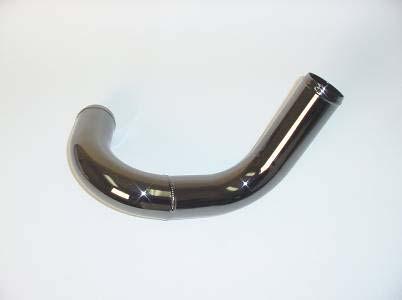
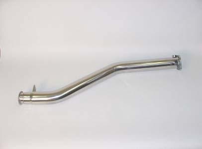
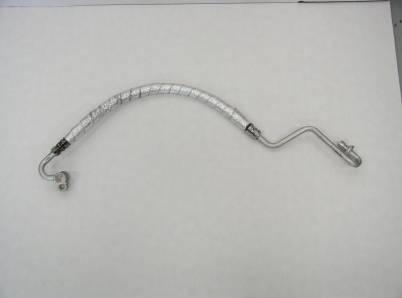
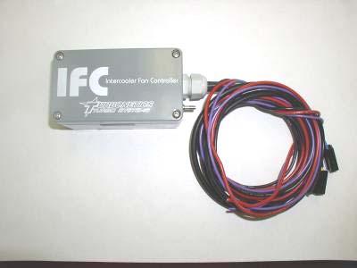
3 TORQUE RECOMMENDATION: When removing and re-installing factory fasteners, refer to the Infiniti / Nissan service manual for torque values. When installing fasteners included in this kit, refer to the following chart: Fastener Size Torque (Pound-Feet) 1/4" or 6mm /16 or 8mm Torque (Newton-Meters) 3/8 or 10mm NPT fittings 2-3 turns past finger tight TURBOCHARGER SYSTEM PARTS LIST: QTY P/N DESCRIPTION P/N P/N Turbocharger, 60-1 / Stg.5 / Ball Bearing X X Air to Air Intercooler, Spearco X X Wastegate, Evolution X X Blow-off Valve, Raptor X X IFC Kit Intercooler Fan Controller X X Hardware Kit, Hoses / Clamps X X Hardware Kit, Nuts / Bolts / Fittings X X Hardware Kit, Gaskets / Misc. X X Hardware Kit, Fuel Components X X Hose, Nitrile Close Radius 90 deg. X X ECU Return Box Kit X X Tube, Turbocharger to Intercooler X X Tube, Intercooler to MAF Sensor 1 X X Tube, Intercooler to MAF Sensor 2 X X Tube, Intercooler to MAF Sensor 3 X X Tube, MAF Sensor to Throttle Body X X Tube, Air filter to Turbocharger X Tube, Exhaust, Crossover X X X Tube, Exhaust, U-bend X X Tube, Exhaust, Y-pipe X X Tube, Exhaust, Turbine Hsg. Inlet X X Tube, Exhaust, Downpipe 1 X X Tube, Exhaust, Downpipe 2 X X Tube, Exhaust, Wastegate Discharge 1 X X Tube, Exhaust, Downpipe 3 (No Cat.) X Tube, Exhaust, Downpipe 3 (With Cat.) X Tube, Exhaust, Wastegate Discharge 2 X X Tube Assembly, Replacement A/C line X X Heat Shield, Tangential T4 housing X X Support Bracket, Downpipe - 3 X Air Filter, AEM Dry-Flow, 3.0 Inlet X X X Install Instructions X X 60154_revB Page 3 of 42
4 QTY P/N DESCRIPTION QTY P/N DESCRIPTION HARDWARE KIT# (HOSES / CLAMPS) PARTS LIST: 3 FT Oil Supply Hose, -3 Fittings Silicone Hose Coupling, Silicone Hose Coupling, Silicone Hump Connect, Silicone 45 Elbow, FT BK Silicone Vacuum Hose, 5/ T-bolt Band Clamp, T-bolt Band Clamp, V-band Clamp V-band Clamp Hose Clamp, 5/8 7 FT Hose, Oil Drain, 5/8 HARDWARE KIT# (NUTS / BOLTS / FITTINGS) PARTS LIST: Fitting, 3/8 NPT x 5/8 Hose, Straight Fitting, 1/8 NPT x 5/32 Hose, Straight Fitting, 1/8 NPT x 5/32 Hose, Elbow Fitting, 1/8 NPT x -3, Straight Fitting, 1/8 NPT x -3, Elbow Fitting, 1/8 NPT, M x M x F Fitting, 1/2" NPT x 5/8 Hose, Hex Bolt, 1/4-20 x 1/2" Lg Hex Bolt, 1/4-20 x 3/4" Lg Hex Bolt, 5/16-18 x 1.0" Lg Hex Bolt, M x 25mm Lg Hex Bolt, M x 20mm Lg Hex Bolt, 1/4-20 x 5/8 Lg Hex Bolt, M x 40mm Lg Hex Bolt, M x 20mm Lg Hex Bolt, M x 30mm Lg Flat Washer, 5/16 or M Flat Washer, M Flat Washer, 1/4" or M Lock Washer, 5/16 or M Lock Washer, M Lock Washer, 1/4 or M Hex Nut, 1/ Hex Nut, M Hex Nut, M Stud, M x 42mm Lg Stud, M x 30mm Lg Hex Plug for O2 Bung, M Socket Hd. Bolt, M x 50mm Lg. HARDWARE KIT# (GASKETS / MISC.) PARTS LIST: Gasket, W gate Disch.,Evolution Flange, Oil Drain, 1/2 NPT Flange, Wastegate Block Off P Disch. Horn, Raptor Support Bracket, Turbo Mounting Bracket, Intercooler Gasket, Oil Drain, T3/T Gasket, Turbine Inlet, T O-ring, Flange, Raptor Tap, 1/8 NPT Tap, 3/8 NPT Loop Strap, 1.0 dia., 1/4" hole 7.5 FT Heat Shield Wrap, 1.5 Wide HARDWARE KIT# (FUEL COMP TS) PARTS LIST: Spacer, Fuel Injector Adapter, Fuel Injector Fuel Injector, Upgrade Fuel Pump, Upgrade ECU RETURN BOX KIT# PARTS LIST: ECU Return Box Pair of Foam Inserts Fedex Return Label Serial No. Decal, White Electronic Mat l Decal, Red 60154_revB Page 4 of 42


5 P/N P/N 5-47 P/N P/N P/N P/N P/N P/N P/N P/N P/N P/N _revB Page 5 of 42


6 P/N P/N P/N P/N P/N P/N P/N P/N P/N P/N P/N P/N _revB Page 6 of 42


7 P/N P/N P/N P/N P/N P/N P/N _revB Page 7 of 42
8 THIS PAGE LEFT BLANK INTENTIONALLY 60154_revB Page 8 of 42


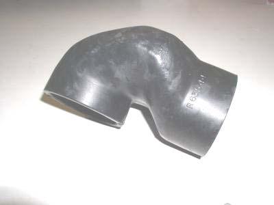
9 PREREQUISITE STEPS: Before getting your hands dirty while under the hood, there are 2 prerequisite steps. See the following 2 sections for detailed instructions regarding A/C Tube Replacement and ECU Removal & Shipping. A/C TUBE REPLACEMENT: The first prerequisite step is to have a replacement air conditioning tube assembly (included in the kit) installed by a professional A/C technician. This is necessary because the turbocharger is located very close to this A/C tube in its factory location, so a replacement shielded tube assembly is supplied to move it away from the hot turbocharger. HAZARDOUS: Do not attempt to perform this step without proper training or equipment. Take your car to a local auto repair shop that is capable of discharging and recharging the A/C system on your car, and have them perform the following 8 steps. Don t forget to bring the replacement part, P/N (FIGURE 1). 1. Turn the ignition switch to the OFF position & disconnect the battery. 2. Using factory recommended procedures, evacuate (discharge) the A/C system. 3. Remove factory air filter box assembly to provide easy access to the A/C tube being replaced. FIGURE 1 4. Remove factory A/C tube, as shown in FIGURES 3 and 4. Tube routes from the A/C compressor (front, driver s side of engine) on one end, towards the front-mount heat exchanger on the other end. FIGURE 3 FIGURE _revB Page 9 of 42

10 5. Install replacement A/C tube assembly (P/N 21213) in same location. See FIGURE 5. FIGURE 5 6. Using factory recommended procedures, re-fill (charge) the A/C system. Check for leaks. 7. Re-install the factory air filter box assembly, and reconnect the battery. 8. Start the car, turn on the A/C system & re-check for leaks. ECU REMOVAL & SHIPPING: Once the A/C tube is replaced and working properly, the 2nd prerequisite step is to remove the ECU (Engine Control Unit) from the car, and ship it to Turbonetics to load the new engine management program, tuned specifically for your car with this turbo setup. NOTE 1: You ll want to perform this step just before you are ready to start working on the car. When you receive your ECU back from Turbonetics, it will be re-programmed for a turbocharged engine and therefore will no longer work properly with your naturally aspirated stock engine. The included ECU return box kit (P/N 11103) includes a pre-paid Fedex shipping label for express shipping, so you can expect to receive your ECU back in 2-3 days. NOTE 2: If, in the future, you choose to remove the turbocharger system (for example, before selling the car), it is possible to re-program your ECU back to naturally aspirated stock specs. At that time, contact Turbonetics customer service staff for details. 9. Turn the ignition switch to the OFF position & disconnect the battery. 10. Remove the ECU, located behind the passenger-side lower dashboard. Refer to the Nissan / Infiniti service manual for more detailed instructions, but listed below is a general guideline on how to do this: Remove the bottom black plastic panel that is underneath the glove box by slowly pulling it downwards and pulling back straight at you (SEE FIGURE 6) _revB Page 10 of 42


 Upon removing")

11 FIGURE 6 FIGURE 7 Remove the passenger side kick panel by removing the plastic nut on the firewall. The nut should be lose enough to be removed with your fingers (SEE FIGURE 7). To remove the glove box, start by unscrewing two Phillips screws on the bottom of the glove box (SEE FIGURE 8) FIGURE 8 FIGURE 9 Open the glove box, and unscrew the four Phillips screws on the top (SEE FIGURE 9) Upon removing the last screw on the top, support the glove box from the bottom with one hand while unscrewing the last screw with the other Carefully set the glove box to the floorboard of the vehicle 60154_revB Page 11 of 42


.")

12 FIGURE 10 Locate the ECU and remove the electrical connectors & fasteners holding it in place. Unplug the ECU by pulling back on lever on the connector and slowly pull down on the connector (SEE FIGURE 11 & 12). FIGURE 11 FIGURE 12 Remove the 10mm nut on the top and bottom of the ECU bracket (SEE FIGURE 13 & 14) FIGURE 13 FIGURE _revB Page 12 of 42
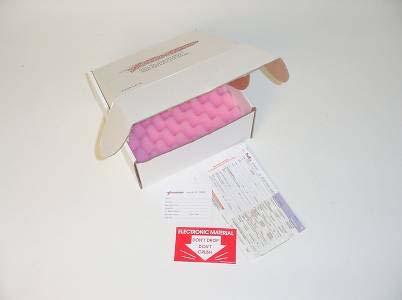
 to the ECU in the location pointed out in FIGURE 15, and fill out the information on the label with a permanent black pen or thin-tip marker.")
 Mailing Address (Where should we ship your ECU back to you?) Phone Number (How can we contact you, if any problems arise?")
13 11. Once removed from the car, attach the Serial No. decal (P/N 31039) to the ECU in the location pointed out in FIGURE 15, and fill out the information on the label with a permanent black pen or thin-tip marker. NOTE: All ECU s received with incomplete or illegible decals will be returned or discarded, so please print clearly and completely! First & Last Name (Who are you?) Mailing Address (Where should we ship your ECU back to you?) Phone Number (How can we contact you, if any problems arise?) Model Year / Manufacturer Name / Model Name (For example: 2003 Nissan 350Z Touring) Manufacture date of car (Located on driver side door jam; See FIGURE 16) Transmission Type (Manual or Automatic) V.I.N. number (Also located on driver side door jam; See FIGURE 16) FIGURE 15 FIGURE Package your ECU in the return box (P/N 31009), using the supplied foam packaging inserts (P/N 31011). Fill in your address on the Fedex return label (P/N 31038), and apply it to the outside of the box. Seal the box closed with the supplied Electronic Mat l decal (P/N 31043). 13. Logon to or to find the nearest Fedex package drop-off location, and ship your ECU return box to Turbonetics _revB Page 13 of 42
14 THIS PAGE LEFT BLANK INTENTIONALLY 60154_revB Page 14 of 42
 will make installation a lot easier.")
. B.")


15 TIME TO GET YOUR HANDS DIRTY: With the prerequisite steps done, and the car parked for a few days (without an ECU), its time to start working under the hood. The steps from this point forward will progress smoother if you are prepared with the supplies listed on page 2, and although not necessary, the ability to lift the vehicle more than a few feet (i.e. a hydraulic lift) will make installation a lot easier. NOTE: The following steps dictating removal of factory parts are purposely generic; refer to the Nissan factory service manual for more detailed instructions and torque specs for all fasteners. 14. Remove the factory fuel pump assembly. A. Remove the lower potion of the rear seat by using both hands and gently lifting up on the front part of the seat one side at a time. (SEE FIGURE 17). B. Remove metal access cover by unscrewing the four Phillips screw clockwise and temporarily push off to the side (SEE FIGURE 18). FIGURE 17 FIGURE 18 C. Remove 6 hex bolts, disconnect the electrical connection CAUTION: Fuel will squirt out during the removing process of the fuel hose. Make sure you have shop rag handy to cover the fuel hose prior to removal of the hose from the barb fitting. NOTE: Now would be a good time to extinguish your cigarette & remove any other flammable items from the area. D. Remove the fuel connection from the top of the pump assembly by depressing both clip on the hose connection simultaneously and pull back slowly (SEE FIGURE 19 & 20). E. Carefully pull out the fuel pump assembly (SEE FIGURE 21), and cover the exposed gas tank. FIGURE 19 FIGURE _revB Page 15 of 42


. D.")
16 FIGURE Sit down at a large open table, and prepare to disassemble the fuel pump assembly, per the following steps: (You will need a small flathead screwdriver, needle nose pliers, 7/64 and 3/8 drill bits and metal / wire cutters) A. Release the plastic clip that holds the 2 halves of the spring-loaded assembly together. Be careful not to stress or break any of the electrical wires. Set aside the coil springs. Unclip and release the electrical connector. B. Remove the plastic retainer clip (pointed out in FIGURE 22), black rubber damper, and fuel pump from the top half of the pump assembly. FIGURE 22 FIGURE 23 C. Remove the filter bag by releasing the metal retaining ring from the bottom of the fuel pump (pointed out in FIGURE 24). D. Break off the small plastic tabs on the topside of the new fuel pump (P/N 31002) as shown in FIGURE 25. This is necessary because the new fuel pump is slightly taller than the factory pump, and these tabs keep it from installing properly _revB Page 16 of 42

 and drill out the bottom orifice using a 7/64 drill bit, only until the drill breaks through the first thickness of sheetmetal (about 1/16")
 from your local Nissan dealership.")

17 FIGURE 24 FIGURE 25 E. Install the filter bag and metal retaining ring on the new fuel pump in the same location. F. Remove the rubber seal (pointed out in FIGURE 26) from the factory pump and install on the new pump in the same location. G. Install the new pump into the fuel pump assembly by reversing the previous few steps. H. Remove the factory fuel pressure regulator by removing the plastic retainer clip pointed out in FIGURE 27, and prying the regulator out with a small flathead screwdriver. I. Carefully hold the regulator in a bench vice (or similar) and drill out the bottom orifice using a 7/64 drill bit, only until the drill breaks through the first thickness of sheetmetal (about 1/16 deep) SEE FIGURE 28. This step is necessary because the orifice size restricts the flow capacity of the upgraded fuel pump. Deburr the hole, and thoroughly clean out any remaining metal chips. NOTE: Take special care during this step, as this regulator is not available (as a replacement part) from your local Nissan dealership. If you destroy this part, the dealership will only sell you the whole pump assembly! FIGURE 26 FIGURE 27 J. Remove & discard the yellow plastic fuel nozzle pointed out in FIGURE 29. Again, this step is necessary because the orifice size in this nozzle restricts the flow capacity of the upgraded fuel pump. K. Carefully hold the bottom half of the white plastic fuel pump housing in a bench vice (or similar) and drill (3) 3/8 diameter holes in the side of the housing, as shown in FIGURE 29. Location is not critical, as long as the holes are near the bottom edge of the housing. Note: It important the holes are drilled as close to the bottom as possible to allow fuel to reach the pump at all times _revB Page 17 of 42

. 20.")
.")

18 L. Re-assemble the fuel pump assembly by reversing the previous steps. FIGURE 28 FIGURE Re-install the factory fuel pump assembly into the car, by reversing step Remove the strut tower brace. 18. Remove factory air filter box assembly and intake tube. 19. Remove plastic intake cover (with the Infiniti logo). 20. Remove top half of upper intake plenum (FIGURE 30). 21. Remove bottom half of upper intake plenum (FIGURE 31). NOTE: Once complete, plug the 6 intake runner holes with a shop rag, so that loose nut & bolts don t fall into the engine You don t want to have to take the engine apart to retrieve lost parts! FIGURE 30 FIGURE Remove electrical connectors on all 6 fuel injectors, and push aside. 23. Remove the bolts holding down the fuel rail _revB Page 18 of 42
, and pull the injectors out of the fuel rail.")
 next to each other, and perform the following: A.")
 onto the top of the new injectors with the larger diameter facing down towards the body of the injector (pointed out")

19 24. Pull up on each side of the fuel rail to pull the injectors out of the lower intake plenum (SEE FIGURE 32). 25. Remove the metal retainer clips holding the fuel injectors to the fuel rail (pointed out in FIGURE 32), and pull the injectors out of the fuel rail. NOTE: There will be some residual fuel in the rail, so be prepared to get wet. FIGURE 32 FIGURE Sit down at a large open table, layout the 6 factory injectors and the 6 new injectors (P/N 31001) next to each other, and perform the following: A. Remove the o-ring seals from the bottom of the factory injectors, and slide them onto the bottom of the new injectors. B. Remove the o-ring seals and fuel-rail seals from the top of the new injectors. C. Install the injector adapters (Round aluminum part w/ 2 diameters; P/N 21211) onto the top of the new injectors with the larger diameter facing down towards the body of the injector (pointed out in FIGURE 33). D. Remove the o-ring seals from the top of the factory injectors, and slide them onto the top of the new injectors, over the adapters. The finished injectors should look like the one pointed out in FIGURE With all o-ring seals transferred to the new injectors, you re almost ready to install the new injectors back into the car. Install the round injector spacers (P/N 21210) into the injector holes in the lower intake plenum, so that the new injectors will sit on top of them (pointed out in FIGURE 34). 28. Carefully install the new injectors into the fuel rail, facing the same direction as the factory injectors. You will not re-use the factory metal retainer clips. FIGURE 34 FIGURE _revB Page 19 of 42
. 31. Cut a length of 5/8 I.D.")


, the front bumper cover, styrofoam bumper pad, aluminum front")
20 29. Re-install and bolt down both fuel rails, taking care while pressing each injector down into the lower intake plenum, to make sure each injector is properly seated on the injector spacers. Re-connect the electrical connectors to the injectors. 30. Remove the factory valve cover breather hose (pointed out in FIGURE 36). 31. Cut a length of 5/8 I.D. rubber hose (P/N 30827) to 5-1/2 feet. Install this hose in place of the factory hose removed in the previous step, re-using factory hose clamps on both ends. Temporarily route the hose towards the front drivers side of the car until later in the instructions. 32. Remove the driver s side exhaust manifold heat shield (pointed out in FIGURE 37). This is easier to accomplish from the topside of the engine. FIGURE 36 FIGURE Re-install both halves of the upper intake plenum, as well as any removed hoses, clamps or electrical connectors, reversing steps 20 & 21. Don t re-install the plastic intake cover or strut tower brace at this time. 34. Lift the front half of the car, and take all necessary safety precautions to secure the vehicle. 35. Remove the plastic splashguard from under the front bumper cover, the plastic inner fenders (in front of the wheels), the front bumper cover, styrofoam bumper pad, aluminum front bumper, and any remaining plastic fascia pieces (SEE FIGURES 38-40). Although not necessary, it is convenient to remove the front wheels. FIGURE 38 FIGURE _revB Page 20 of 42
.")

 to the right side of the cooler, rotated 180 degrees from its")
 inside the passenger side fender well (as shown in FIGURE 43 & 44) re-using the factory mounting hardware removed in step A.")
21 36. Relocate the power steering cooler to the passenger side inner fender well, per the following steps: A. Remove power steering cooler complete with mounting brackets from its mounting position, and disconnect the rubber hose connection (pointed out in FIGURE 39). NOTE: Be prepared with a drain pan to catch the used power steering fluid. FIGURE 40 FIGURE 41 B. Remove all metal tubing and rubber hoses, all the way back to the hose connection under the power steering fluid reservoir, in the passenger side inner fender well (circled in FIGURE 42). C. Remove both mounting brackets from the cooler, and re-mount the left bracket (pointed out in FIGURE 41) to the right side of the cooler, rotated 180 degrees from its original orientation. Look closely at FIGURE 44 to see the orientation of the bracket (pointed out by the arrows). D. Mount the cooler (with rotated bracket) inside the passenger side fender well (as shown in FIGURE 43 & 44) re-using the factory mounting hardware removed in step A. Re-use one of the factory tapped holes to fasten the bracket to the fender well sheet metal. E. Re-connect the rubber hoses (circled in FIGURE 42) to the cooler, using factory hose clamps. NOTE: It may be necessary to cut an inch or two off the length of one of the hoses; use best judgment. FIGURE 42 FIGURE _revB Page 21 of 42


. 41. Carefully thread the hole using the supplied 3/8 NPT tap. The tap only needs to go into the casting far enough to create full threads (approx.")

22 FIGURE 44 FIGURE Remove front sway bar mounting brackets (shown in FIGURE 45) connected to the frame rail, so that the sway bar dangles loosely under the car. This step is optional, but makes the next few steps easier. 38. Drain the engine oil, and remove the oil pan. 39. Using a center punch, mark and score the location of the oil drain. Hole should be centrally located between the cast ribs of the engine block as shown in FIGURE 46 & Using a step drill or 1/8 drill bit, drill a pilot hole into the engine block. Increase drill bit sizes in small increments up to 9/16 hole. NOTE: Be careful not to push too hard when drilling, so as to avoid hitting any internal engine components when the drill bit breaks thru the casting (use of a step drill will help prevent this from happening). 41. Carefully thread the hole using the supplied 3/8 NPT tap. The tap only needs to go into the casting far enough to create full threads (approx. 3/8 ), no further. NOTE: It is recommended to hand turn the tap, to avoid cross threading. This is a critical process you don t want to cross thread the engine block! FIGURE 46 FIGURE Deburr hole and thoroughly clean out any metal chips from inside of engine block. Install the 3/8 NPT x 5/8 hose barb fitting (P/N 30133), using NPT thread sealant. 43. Scrape off the excess factory sealant. Apply a new bead of high temp. RTV sealant to the oil pan sealing surface, and re-install the oil pan _revB Page 22 of 42
 to 5.0 feet. Wrap P/N 21184 (Exh. Tube Ass y, Turb. Housing Inlet) as seen in FIGURE 49.")

. Install P/N 21184 (Exh. Tube Ass y, Turb.")

23 44. Remove the factory exhaust system (SEE FIGURE 46) from the 3-bolt manifold-to-cat flange back to the 2- bolt flange (just before the first muffler). 45. Cut a length of heat shield wrap (P/N 31007) to 5.0 feet. Wrap P/N (Exh. Tube Ass y, Turb. Housing Inlet) as seen in FIGURE 49. The heat wrap is adhesive backed, so it should stay in place, but as an added measure you may want to secure the end with a zip tie or steel wire. FIGURE 48 FIGURE 49 NOTE: During the next few steps, only loosely secure the new exhaust tubes in place. Once all exhaust tubes are loosely installed, go thru and tighten all the hardware & clamps. 46. Loosen the left factory hex bolt and remove the right hex bolt holding the A/C compressor in place (pointed out in FIGURE 50). Install P/N (Exh. Tube Ass y, Turb. Housing Inlet) tube into position as shown in FIGURE 51, using the A/C bolts to loosely secure it in place. FIGURE 50 FIGURE 51 LEFT RIGHT 47. Either before or after loosely installing the Turb. Housing Inlet tube, install the Turbo Support Bracket (P/N 21202) circled in FIGURE 52, by loosening another of the A/C compressor bolts (on the driver s side top), and sliding the slotted end of the bracket under the loosened A/C bolt. The end of the bracket with the hole should line up with one of the holes in the turbocharger inlet flange (SEE FIGURE 52) _revB Page 23 of 42
 in its place.")
 into position shown in FIGURE 54, loosely securing it to the previous tube with v-band clamp P/N 31073.")
 into the boss in this U-bend tube, circled in FIGURE 54. Recommend using anti-seize lubricant on this connection. FIGURE 53 FIGURE 54 51.")
24 FIGURE Install P/N (Exh. Tube Ass y, Y-Pipe) into position shown in FIGURE 53, loosely securing it to the previous tube with v-band clamp P/N Remove factory O2 sensor near the 3-bolt flange on the driver s side exhaust manifold, and install the O2 sensor plug (P/N 30862) in its place. The (2) factory O2 sensors can be disconnected and set aside for now. They will be re-installed later in the instructions. 50. Install P/N (Exh. Tube Ass y, U-bend) into position shown in FIGURE 54, loosely securing it to the previous tube with v-band clamp P/N Attach & tighten the other end of the tube to the exhaust manifold, re-using one of the factory studs & nuts, and (2) M10 x 40mm hex bolts, lockwashers & nuts (Part Hardware Kit# 11098). Attach & tighten the O2 sensor (removed in the previous step) into the boss in this U-bend tube, circled in FIGURE 54. Recommend using anti-seize lubricant on this connection. FIGURE 53 FIGURE Install P/N (Exh. Tube Ass y, Downpipe 2) into position shown in FIGURE 55, loosely holding it in position with steel wire, not fastened to anything. This is done now, because it is more difficult to install later in the instructions. 52. Install both secondary O2 sensor as shown in FIGURE 51. It does not matter which sensor goes first or second _revB Page 24 of 42


 into position shown in")


.")
25 53. Wrap all the wires near the transmission that will come in contact with the cross over pipe with the supplied heat shield wrap as shown in FIGURE FIGURE 55 FIGURE 56 FIGURE 57 FIGURE Install P/N (Exh. Tube Ass y, Crossover) into position shown in FIGURE 60, loosely securing it to the Ypipe tube with v-band clamp P/N Attach & tighten the other end of the tube to the exhaust manifold, reusing one of the factory studs & nuts, and (2) M10 x 40mm hex bolts, lockwashers & nuts (P/Ns 31003, 30805, 30803). FIGURE 59 FIGURE _revB Page 25 of 42
 and light-yellow-colored tubing (behind it & closer to engine) towards the engine as far as possible, as seen in the picture. 57.")
 as shown in FIGURE 65.")
 around the A/C hose from the previous step, and secure it in the same place as the dipstick guide bracket, re-using the factory hex bolt.")
26 FIGURE Lower the front half of the car. 56. In order to provide clearance for the turbocharger, it is necessary to bend 2 of the aluminum A/C tubes out of the way. Bend the silver-colored tubing (pointed out in FIGURE 62) and light-yellow-colored tubing (behind it & closer to engine) towards the engine as far as possible, as seen in the picture. 57. Remove dipstick and dipstick guide bracket (pointed out in FIGURE 63). FIGURE 62 FIGURE 63 PUSH HERE AND HERE HEAT WRAP 58. In order to protect the A/C line from burning, it is critical to wrap the A/C hose pointed out in FIGURE 58 with heat shield wrap (P/N 31007) as shown in FIGURE 65. If you have extra heat wrap, you may want to doublewrap this hose. Secure the open end with a zip tie or steel wire. 59. Install the loop strap (P/N 31006) around the A/C hose from the previous step, and secure it in the same place as the dipstick guide bracket, re-using the factory hex bolt. All this, to keep these parts shielded from the turbocharger heat. 60. Remove (1) 10mm bolt as shown in FIGURE 59. Lift bracket and tuck A/C line behind bracket. Tighten bracket bolt _revB Page 26 of 42
 to it.")

 M10 x 42mm studs and (1) turbine inlet gasket (P/Ns 30806, 30263) onto the turbine inlet flange as circled in FIGURE 71. 63.")
27 FIGURE Install (2) M8 x 30mm studs into the wastegate flange on P/N (Exh. Tube Ass y, Downpipe 1). Install this tube into position shown in FIGURE 66, loosely securing it to the Downpipe 2 tube with v-band clamp P/N While in the car, connect P/N (Exh. Tube Ass y, W gate Disch.) to it. Attach & tighten the 2 parts together at the wastegate flange with (1) wastegate gasket, and (2) M8 lockwashers & nuts (P/Ns 20142, 30593, 30653). NOTE: It is not possible to bolt these 2 parts together beforehand, it must be done on the car. The W gate tube has the same flange on both ends, so the correct orientation will have the end with the bellows facing the ground. This tube is pointed out in FIGURE 71. FIGURE 65 FIGURE Install (3) M10 x 42mm studs and (1) turbine inlet gasket (P/Ns 30806, 30263) onto the turbine inlet flange as circled in FIGURE Place the turbocharger on a nearby open table, and install the following parts. Don t forget to use NPT thread sealant on all NPT fittings, and remove all protective covers and tags from the turbocharger. (1) Oil drain gasket, and (1) Oil drain flange (1) 1/2" x 5/8 hose barb 45-degree fitting (Orient the fitting as shown in FIGURE 72) (2) M8 x 20mm hex bolts, lockwashers & nuts (1) 1/8 NPT x 5/32 90-degree hose fitting (installed into the port on the compressor housing discharge, facing the same direction as the compressor discharge) 64. Install and orientate the nitrile hose connector to the inlet of the compressor housing and tighten using the 3.0 T-bolt (P/N ) that is supplied as shown in FIGURE _revB Page 27 of 42


28 FIGURE 67 FIGURE 68 FIGURE Notch plastic radiator core support on the upper core support area as shown in FIGURE 70. FIGURE 70 Remove 66. Bend aluminum A/C line slightly to make room for the turbocharger as necessary _revB Page 28 of 42
 5/8 hose clamps (P/N 30817), one clamp on each end of the hose. FIGURE 71 FIGURE 72 68.")


 will go thru the turbine housing, turbine inlet flange & previously installed turbo support bracket.")
29 67. Cut a length of 5/8 I.D. rubber hose (P/N 30827) 20 to 22. Attach & tighten this hose to the oil drain fitting from the previous step, using (2) 5/8 hose clamps (P/N 30817), one clamp on each end of the hose. FIGURE 71 FIGURE Bend the aluminum A/C tubing (pointed out in FIGURE 63) approx. 90 degrees downward over the frame rail as shown in the picture, just enough to provide adequate clearance for the turbocharger oil drain fitting. Temporarily install the turbocharger to check clearance, and bend more as needed. Note: It is important that you make sure the aluminum A/C line is not rubbing on anything. 69. Apply a bead of high temp. RTV sealant to the rectangular downpipe flange face, pointed out in FIGURE 68. FIGURE 73 FIGURE Attach & tighten the turbocharger to the turbine inlet flange, using (3) M10 flatwashers, lockwashers & nuts, and (1) M10 x 50mm socket head screw & flatwasher thru the 4 th hole. This 4 th fastener (pointed out in FIGURE 75) will go thru the turbine housing, turbine inlet flange & previously installed turbo support bracket. Tighten it using (1) M10 lockwasher & nut on the underside of the support bracket, and also tighten the factory (A/C compressor) hex bolt holding the turbo support bracket. Temporarily route the 5/8 oil drain hose down towards the fitting attached to the engine block. 71. Attach & tighten the Downpipe 1 (pointed out in FIGURE 76) tube to the turbocharger turbine housing, using (4) M x 20mm hex bolts & lockwashers. Tighten the v-band clamp between the Downpipe 1 and Downpipe 2 tubes _revB Page 29 of 42
 to that fitting, and temporarily route the hose down towards the bottom front of the engine. 73.")
, lock washers (P/N 30593), and flat washers (P/N 30589), secure the Evolution wastegate to the new turbo inlet pipe (P/N 21184 rev.b).")
 with the supplied block off plate (P/N 20251). Make sure there is a gasket (P/N 20142) between the flanges.")
30 FIGURE 75 FIGURE Install the 1/8 NPT x 3 90 degree oil fitting (P/N 30551) to the filter fitting atop the turbo center housing, using NPT thread sealant. Install the braided oil supply hose (P/N 10721) to that fitting, and temporarily route the hose down towards the bottom front of the engine. 73. Lift the front half of the car, and take all necessary safety precautions to secure the vehicle. 74. Using the supplied M bolts (P/N 31076), lock washers (P/N 30593), and flat washers (P/N 30589), secure the Evolution wastegate to the new turbo inlet pipe (P/N rev.b). SEE FIGURE 77 & 78 FIGURE 77 FIGURE Block off the original wastegate mounting flange on the turbo inlet pipe (P/N rev.b) with the supplied block off plate (P/N 20251). Make sure there is a gasket (P/N 20142) between the flanges. Secure the block off flange to the pipe using existing hardware. SEE FIGURE 77 & Mount the sway bar back onto the chassis and route the A/C line as shown in FIGURE _revB Page 30 of 42
, lock washers (P/N 30593), and flat washers (P/N 30589) making sure there is a gasket (P/N 20142) in between each flange.")
 using V-band clamp P/N 30232 to connect to the second downpipe, and (2) M10 x 40mm hex bolts,")
31 77. Bolt one side of the new supplied wastegate dump tube (P/N 21427) to the to discharge side of the wastegate and bolt the other side to the original wastegate dump tube (P/N 21200) using the supplied M bolts (P/N 31076), lock washers (P/N 30593), and flat washers (P/N 30589) making sure there is a gasket (P/N 20142) in between each flange. SEE FIGURE FIGURE 79 FIGURE 80 FIGURE Install the third Downpipe (P/N or 21204, depending on which turbocharger system you purchased) using V-band clamp P/N to connect to the second downpipe, and (2) M10 x 40mm hex bolts, flatwashers, lockwashers & nuts to connect to the 2-bolt flange. 79. Install P/N (Support Bracket, Downpipe 3), using the 2 factory transmission bolts pointed out in FIGURE 82 on one end, and (2) M8 x 25mm hex bolts, lockwashers & nuts to connect to the bracket on the downpipe on the other end. Use M8 flatwashers on both sides of the bracket, total of (4). 80. Install (2) O2 sensor plugs (P/N 30862) into the welded bosses near the rear of the downpipe, pointed out in FIGURE 83. These bosses are for optional O2 sensors _revB Page 31 of 42

 away from hot exhaust pipes, and secure with zip ties. If any heat shield wrap is left over, use as needed. 82.")
 A. Remove the electrical connector and the oil pressure sensor from the engine block (circled in FIGURE 84) B.")
 into the re-tapped hole (pointed out in FIGURE 85) D.")
32 FIGURE 82 FIGURE 83 NOTE: Now that all exhaust tubes are loosely installed, go thru and tighten all the hardware & clamps. 81. Install the bottom half of the 5/8 oil drain hose to the oil drain fitting in the block, and secure with the attached hose clamp. Cut the length of the hose to suit, so that no part of the hose is lower than the fitting in the block. Route the hose (downward from the turbocharger) away from hot exhaust pipes, and secure with zip ties. If any heat shield wrap is left over, use as needed. 82. Install the bottom half of the braided oil supply hose to the engine (pictures of bottom front of engine), per the following steps: (Be sure to use NPT thread sealant on all NPT connections) A. Remove the electrical connector and the oil pressure sensor from the engine block (circled in FIGURE 84) B. Using the supplied 1/8 NPT tap (P/N 30808), carefully re-tap the vacated hole in the engine block C. Install the 1/8 NPT Tee fitting (P/N 30562) into the re-tapped hole (pointed out in FIGURE 85) D. Re-install the pressure sensor into the opposite end of the Tee fitting E. Install the 1/8 NPT x 3 straight oil fitting (P/N 30544) into the third leg of the Tee fitting F. Install the braided oil supply line into the oil fitting from the previous step (SEE FIGURE 85). FIGURE 85 FIGURE _revB Page 32 of 42
 assembly to the car using the factory bolts, as shown in FIGURE 86 & 87. FIGURE 86 FIGURE 87 84.")

 and (1) 2-1/2 coupling hose (P/N 30172-4) and (4) T-bolt clamps (P/N 30275-250), as seen in FIGURE 80 & 81.")
 by removing the 2 factory hex bolts pointed out in FIGURE 90 & 91, and fastening the intercooler")
33 83. Install the mounting brackets (P/N 21203) to the intercooler end tanks, using (2) 1/4-20 x 1/2 hex bolts & lockwashers. Install the intercooler (P/N 5-312) assembly to the car using the factory bolts, as shown in FIGURE 86 & 87. FIGURE 86 FIGURE In the driver s side fender well, pull the factory wiring harness pointed out in FIGURE 80 away from the sheetmetal, to provide clearance for the intercooler tubing to fit under it. Install P/N (Tube Ass y, Turbo to I/C) from the turbocharger compressor discharge to the driver s side intercooler inlet, using (1) 2-1/2 hump hose (P/N ) and (1) 2-1/2 coupling hose (P/N ) and (4) T-bolt clamps (P/N ), as seen in FIGURE 80 & 81. Use the coupling hose at the intercooler connection. 85. Install P/N (Tube Ass y, I/C to MAFS 2) by removing the 2 factory hex bolts pointed out in FIGURE 90 & 91, and fastening the intercooler tube to the engine using these bolts. It may be convenient to install the 45- degree hose coupling (P/N ) and (2) T-bolt clamps (P/N ) to the upper end of the tube before installing it on the car. FIGURE 88 FIGURE _revB Page 33 of 42
 from the passenger side intercooler outlet to the tube from the previous step, using (1) 2-1/2 hump hose")


 3.0 hose coupling (P/N 30162-4) and (2) 3.0 T-bolt clamps (P/N 30275-300). FIGURE 94. 89. Carefully route the 5/8 I.D.")
34 FIGURE 90 FIGURE Install P/N (Tube Ass y, I/C to MAFS 1) from the passenger side intercooler outlet to the tube from the previous step, using (1) 2-1/2 hump hose (P/N ) and (1) 2-1/2 coupling hose (P/N ) and (4) T- bolt clamps (P/N ), as seen in FIGURE 92. Use the coupling hose at the intercooler connection. FIGURE 92 FIGURE Modify P/N (turbo heat shield) as shown in FIGURE 93, using sheet metal cutters or heavy-duty scissors. Install the shield over the turbocharger turbine housing, and secure with steel wire. 88. Install P/N (K&N air filter) to the P/N (Tube Ass y, Filter to Turbo) tube, and then install that subassembly to the turbocharger compressor inlet, using (1) 3.0 hose coupling (P/N ) and (2) 3.0 T-bolt clamps (P/N ). FIGURE Carefully route the 5/8 I.D. rubber hose (added in step# 31) along the engine bay inner fender, through the same hole that the first intercooler tube routes through, and connect to the 5/8 hose connection on the filter to turbo tube, re-using the factory hose clamps (pointed out in FIGURE 95). The hose can also be seen pointed out in FIGURE _revB Page 34 of 42
 tube to the factory throttle body, using (1) 3.")


 tube with the factory mass air flow sensor (MAFS)")
35 FIGURE 94 FIGURE Install P/N (Tube Ass y, MAFS to T/B) tube to the factory throttle body, using (1) 3.0 hose coupling (P/N ) and (2) T-bolt clamps (P/N ), as shown in FIGURE Remove the o-ring on the air flow meter flange and apply a small bead of silicone (around thick) in the groove. Make sure you do not over apply silicone. Apply only enough to seal the flange between the mass air sensor flange to the boost tube flange (SEE FIGURE 96 & 97). FIGURE 96 FIGURE Pre-assemble P/N (Tube Ass y, I/C to MAFS 3) tube with the factory mass air flow sensor (MAFS) housing, using (4) 1/4-20 x 3/4 hex bolts, flatwashers, lockwashers & nuts. Install a 3.0 hose coupling (P/N ) and (2) T-bolt clamps (P/N ) to the opposite end of the MAFS housing (SEE FIGURE 99) _revB Page 35 of 42


36 FIGURE 98 FIGURE Loosen the factory bolt from the front side of engine, pointed out in FIGURE 100, and install the previous tube assembly using this bolt, and connecting to the 45-degree hose coupling. The tube in FIGURE 100. Reconnect the electrical connector to the MAFS housing (it may be necessary to cut a factory zip tie, to provide enough slack in the wire harness to reach the new MAFS housing location). Installed assembly can be seen in FIGURE 101. FIGURE 100 FIGURE Install the polished discharge horn (P/N 20732P) into the discharge of the Raptor blow-off valve (P/N 10843) by simply pressing it into place. Mount the valve assembly to the swivel mount on the previous tube, using (1) O- ring (P/N 30468), and (2) 1/4-20 x 5/8 serrated head hex bolts. Orient the valve with the horn facing towards the front of the car and tighten the bolts _revB Page 36 of 42
 1/8 NPT x 5/32 hose fitting into the bottom port of the wastegate, and (1) 1/8 NPT x 5/32 hose")
, and route the hose from the upper intake plenum (port shown in")


37 FIGURE 102 FIGURE Install (1) 1/8 NPT x 5/32 hose fitting into the bottom port of the wastegate, and (1) 1/8 NPT x 5/32 hose fitting into the top port of the blow-off valve, pointed out in FIGURE Cut approx. 2.5 feet of 5/32 vacuum hose (P/N BK), and route the hose from the upper intake plenum (port shown in FIGURE 103) to the blow-off valve fitting. Cut approx. 2.5 feet of the same hose, and route it from the fitting on the wastegate to the fitting on the compressor housing (installed in step# 60). Loosely zip tie the hose as desired. NOTE: The operation of these turbocharger control devices rely on these hoses for pneumatic signals, so do NOT pinch or crimp the hose in any way. 97. Re-install aluminum bumper reinforcement bar and modify foam bumper insert as shown in FIGURE FIGURE 104 FIGURE 105 REMOVE 60154_revB Page 37 of 42


38 FIGURE Remove both foam inserts from the front bumper as shown in FIGURE 107. Re-install front bumper. FIGURE Re-install all factory hardware that can be re-installed: ECU, sway bar, intake cover, bodywork, etc INSTALLING THE IFC 1. Using the supplied double side taped, secure the IFC to the steel bumper support bracket. SEE FIGURE 108 FIGURE 108 FIGURE _revB Page 38 of 42


39 2. Route the leads from the IFC with the fan plugs to the intercooler and connect them to the intercooler. 3. Using the supplied T-fitting, install it between the vacuum signal from the manifold to the blow off valve. 4. Connect one end of the fitting to the signal to the blow off valve and connect the other to the IFC. Secure silicone hose to the fitting on the IFC with a zip tie. SEE FIGURE Remove the five plastic clip that secure the battery cover and remove cover. Remove the two plastic clips that secure the plastic cowl trim and remove trim. SEE FIGURE 110 FIGURE Route the wires from the IFC to the battery compartment as shown in FIGURE 111. FIGURE _revB Page 39 of 42
 Black Wire Negative (-) 8.")


40 7. Connect the red and black wires from the IFC to the terminals of the battery. SEE FIGURE 112 FIGURE 112 Red Wire Positive (+) Black Wire Negative (-) 8. Lift cover of the fuse box that is to the left of the battery by pulling upwards. SEE FIGURE 113 FIGURE 113 FIGURE Locate the windshield washer fuse, which is the forth fuse down on the right side. Using the supplied fuse tap, remove the fuse and slide one of the contacts onto the tap and re-insert the fuse into place. You may refer to the top of the fuse box lid to locate the fuse. 10. Route the purple wire from the IFC following the other factory wires to the fuse tap so you can re-install the cover. SEE FIGURE _revB Page 40 of 42
41 FINAL CHECKLIST: Review these instructions to make sure that all fasteners, clamps & electrical connections have been installed & torqued correctly. Check that all hose routings are free of any kinks or near any hot or abrasive surfaces, that may cause wear over time. Adjust or reroute as necessary to provide adequate slack for engine movement. Refill all fluids (oil & power steering) to factory recommended levels. The use of synthetic oil (with the factory recommended oil weight) is strongly recommended, as it will prolong the life of the turbocharger. Regardless of factory recommended intervals, the addition of a turbocharger requires that the oil be changed every 3000 miles. The use of premium octane unleaded fuel is required for proper engine performance and to reduce the possibility of internal engine damage from detonation. Cycle the ignition to the ON position several times to pressurize the fuel system & check for any leaks. Start the vehicle and check for any oil, power steering or air pressure leaks. It is recommended that you do not drive your vehicle aggressively if the fuel level is below ¼ tank. NOTE: It is normal for the vehicle to emit some amount of white smoke & a strange odor for an hour or two of operation, as the oils within the exhaust pipes burn off _revB Page 41 of 42
42 NO FAULT / NO HASSLE WARRANTY PROGRAM: TURBONETICS will repair or replace, at our expense, any new TURBONETICS / Spearco products that fail, including products used in racing or competition applications, for a period of one year from the original date of purchase. All turbocharger and cartridge assemblies have a factory installed inline oil filtration device. This filter device must remain in place if any warranty is to be considered under the No-Fault / No-Hassle program. Electrical components that fail due to misuse are not covered under the No-Fault / No-Hassle Warranty Program. Warranty is limited to TURBONETICS products and does not include progressive or subsequential damage and does not cover removal or installation labor or associated parts. No warranty is made for any other claims for special, indirect or consequential damages including but not limited to component removal or installation equipment downtime, prospective profits or other economic loss. Warranty will not be granted for recurring damage, malfunction, or failure due to improper installation, misuse, unauthorized repair or alterations, or externally induced physical damage. Warranty is non-transferable and must be processed via the original purchaser from TURBONETICS. Remanufactured units, performance upgraded units, and O.E.M. replacement units are covered by a 90-day warranty or the O.E. warranty period. TURBONETICS highly recommends that the installation of mechanical or electrical parts be performed by trained professionals. Improperly installed products may lead to unsafe and unreliable conditions. RETURN POLICY: Only unused and complete merchandise may be accepted for return subject to inspection and acceptance by TURBONETICS. No goods will be accepted without prior return authorization from TURBONETICS. Call for approval and RGA (Returned Goods Authorization) tracking number. No returns will be accepted without an RGA tracking number. No returns will be accepted after ninety (90) days from the original shipping date from TURBONETICS unless approved. All approved returns are subject to a 15% restocking charge NO EXCEPTIONS. The original invoice must accompany the return. Accepted warehouse / distributor and open account returns will be issued credit only. RETURNED GOODS AUTHORIZATION TRACKING NUMBER: TURBONETICS will only accept product returns, repair orders / upgrades, and warranty requests that have been approved and are returned with a corresponding RGA (Returned Goods Authorization) tracking number. Contact TURBONETICS for approval and the RGA number. Write the RGA number clearly on the outside of the package and include it inside the package. This is very important in allowing us to properly identify and process your request. Failure to comply with this requirement will result in the delay of processing or the product being returned to you _revB Page 42 of 42
INSTALLATION INSTRUCTIONS. Upgrade Front Intercooler BMW 335 Twin Turbo P/N 15179
 INSTALLATION INSTRUCTIONS Upgrade Front Intercooler 2007- BMW 335 Twin Turbo P/N 15179 Turbonetics, Inc. * 2255 Agate Court * Simi Valley, CA * 805-581-0333 * TurboneticsInc.com READ THIS FIRST: Study
INSTALLATION INSTRUCTIONS. TURBOCHARGER SYSTEMS: 2003 / 2004 Nissan 350Z VQ35 3.5L V6 Engine, Manual Transmission Only
 INSTALLATION INSTRUCTIONS TURBOCHARGER SYSTEMS: 2003 / 2004 Nissan 350Z VQ35 3.5L V6 Engine, Manual Transmission Only P/N 15134 (No Catalytic Converter) P/N 15136 (With Catalytic Converter) P/N 15138 (No
INSTALLATION INSTRUCTIONS. Upgrade Front Intercooler 2001 Early 2006 Chevrolet / GMC Duramax P/N 2-486
 INSTALLATION INSTRUCTIONS Upgrade Front Intercooler 2001 Early 2006 Chevrolet / GMC Duramax P/N 2-486 Turbonetics, Inc. * 2255 Agate Court * Simi Valley, CA * 805-581-0333 * TurboneticsInc.com READ THIS
Intercooler Upgrade Kit
 INSTALLATION INSTRUCTIONS Intercooler Upgrade Kit 04-06 Ford 6.0L P/N 70057 99-03 Ford 7.3L P/N 70058 Turbonetics, Inc. * 14399 Princeton Avenue * Moorpark, CA * 805-581-0333 * TurboneticsInc.com READ
Intercooler Upgrade Kit Kit p/n Mitsubishi Lancer EVO X
 INSTALLATION INSTRUCTIONS Intercooler Upgrade Kit Kit p/n 11647 Mitsubishi Lancer EVO X Turbonetics, Inc. * 2255 Agate Court * Simi Valley, CA * 805-581-0333 * TurboneticsInc.com READ THIS FIRST: Study
INSTALLATION INSTRUCTIONS. TURBOCHARGER SYSTEMS: 2003 / 2004 Nissan 350Z VQ35 3.5L V6 Engine, Manual Transmission Only
 INSTALLATION INSTRUCTIONS TURBOCHARGER SYSTEMS: 2003 / 2004 Nissan 350Z VQ35 3.5L V6 Engine, Manual Transmission Only P/N 15134 (No Catalytic Converter) P/N 15136 (With Catalytic Converter) P/N 15138 (No
Treadstone Performance Engineering Inc, Miami Fl
 INSTALLATION INSTRUCTIONS TURBOCHARGER SYSTEMS: 2007+ Nissan Sentra SER & Spec-V READ THIS FIRST: Study these instructions completely before proceeding. Engine and/or turbocharger damage may occur if any
INSTALLATION INSTRUCTIONS. TURBOCHARGER SYSTEMS: Nissan Spec V. P/N (No Catalytic Converter)
") INSTALLATION INSTRUCTIONS TURBOCHARGER SYSTEMS: 2002-2003 Nissan Spec V P/N 15173 (No Catalytic Converter) Turbonetics, Inc. * 2255 Agate Court * Simi Valley, CA * 805-581-0333 * TurboneticsInc.com READ
INSTALLATION INSTRUCTIONS TURBOCHARGER SYSTEMS: 2002-2003 Nissan Spec V P/N 15173 (No Catalytic Converter) Turbonetics, Inc. * 2255 Agate Court * Simi Valley, CA * 805-581-0333 * TurboneticsInc.com READ
03-04 Mach 1. Hellion Power Systems Mach 1 Kit Instructions
 Hellion Power Systems 03-04 Mach 1 Kit Instructions Part 1 Hellion recommends that the front suspension system be installed either by trained professionals or by 5.Remove rack bolts K-Member Installation
05-08 GT. Hellion Power Systems Mustang Kit Instructions
 Hellion Power Systems 05-08 Mustang Kit Instructions 1. Disconnect Battery 2. Drain Radiator, keep fluid for re-installation. 3. Remove air box and inlethoses. 6. Next, underneath, punch oil pan for turbo
3 October 2016 PN# V Dodge Twin Turbo Kit (I-00274) ½ D o d g e 2 4 v I S B
 ½ D o d g e 2 4 v I S B") 3 October 2016 PN#1045320 24V Dodge Twin Turbo Kit (I-00274) 1 DOWNLOAD ENHANCED INSTALL MANUALS AT dieselperformance.com BD Twin Turbo Kit 1998½- 2 0 0 2 D o d g e 2 4 v I S B Part# 1045320 PLEASE READ
3 October 2016 PN#1045320 24V Dodge Twin Turbo Kit (I-00274) 1 DOWNLOAD ENHANCED INSTALL MANUALS AT dieselperformance.com BD Twin Turbo Kit 1998½- 2 0 0 2 D o d g e 2 4 v I S B Part# 1045320 PLEASE READ
99-04 GT. Hellion Power Systems Mustang GT Kit Instructions
 Hellion Power Systems 99-04 Mustang GT Kit Instructions Part 1 Hellion recommends that the front suspension system be installed either by trained professionals or by 5.Remove rack bolts K-Member Installation
IAG Competition Series Air / Oil Separator (AOS) For 2017 STI
 For 2017 STI") P IAG Competition Series Air / Oil Separator (AOS) For 2017 STI Part# IAG-ENG-7251 Tools Required: Ratchet, torque wrench, extensions, needle nose pliers, hose cutter, snips/scissors, flat head screw driver,
P IAG Competition Series Air / Oil Separator (AOS) For 2017 STI Part# IAG-ENG-7251 Tools Required: Ratchet, torque wrench, extensions, needle nose pliers, hose cutter, snips/scissors, flat head screw driver,
IAG Air / Oil Separator (AOS) For STi
 For STi") IAG Air / Oil Separator (AOS) For 2008-14 STi Part# IAG-ENG-7000 Tools Required: Ratchet, torque wrench, extensions, needle nose pliers, hose cutter, snips/scissors Sockets: 10mm, 12mm 13mm Wrenches: 10mm,
IAG Air / Oil Separator (AOS) For 2008-14 STi Part# IAG-ENG-7000 Tools Required: Ratchet, torque wrench, extensions, needle nose pliers, hose cutter, snips/scissors Sockets: 10mm, 12mm 13mm Wrenches: 10mm,
PART NUMBER: MINI Cooper S L4-1.6L SEE * NOTE
 Equipped with AEM Dryflow Filter No Oil Required! INSTALLATION INSTRUCTIONS PART NUMBER: 21-699 2007-2010 MINI Cooper S L4-1.6L SEE * NOTE * NOTE: Legal in California only for racing vehicles which may
Procharger Stage II Intercooled Supercharger System (11-14 GT)
") Procharger Stage II Intercooled Supercharger System (11-14 GT) Installation Time: Approximately one day. Installed on 2012 Mustang GT 5.0/Manual Required Tools 3/8 Socket Set (Standard and Metric) 1/2
Procharger Stage II Intercooled Supercharger System (11-14 GT) Installation Time: Approximately one day. Installed on 2012 Mustang GT 5.0/Manual Required Tools 3/8 Socket Set (Standard and Metric) 1/2
INSTALL MANUAL D o d g e 1 2 v 6 B T A PLEASE READ ALL INSTRUCTIONS BEFORE INSTALLATION.
 PN#1045310 12V Dodge Twin Turbo Kit (I-00273) 1 INSTALL MANUAL BD Twin Turbo Kit 1994-1 9 9 8 D o d g e 1 2 v 6 B T A Part# 1045310 PLEASE READ ALL INSTRUCTIONS BEFORE INSTALLATION. * Picture as shown
96-04 tt. Hellion Power Systems Mustang Twin Turbo Kit Instructions
 96-04 tt Hellion Power Systems 1996-2004 Mustang Twin Turbo Kit Instructions 1. Disconnect battery and elevate front end of car on either Jack stands or a lift if available 2.Lock steering wheel and remove
4. Remove (4) 10mm and (1) 7mm bolt that holds fascia at front corners, on each side
 10mm and (1) 7mm bolt that holds fascia at front corners, on each side") 2010 Camaro LS3 1. Disconnect battery ground 2. Remove front wheels 3. Remove (5) push pins and (5) #20 torx screws on inner front wheel well liners and remove liners on each side 4. Remove (4) 10mm and
2010 Camaro LS3 1. Disconnect battery ground 2. Remove front wheels 3. Remove (5) push pins and (5) #20 torx screws on inner front wheel well liners and remove liners on each side 4. Remove (4) 10mm and
IAG Competition Series Air / Oil Separator (AOS) For WRX
 For WRX") P IAG Competition Series Air / Oil Separator (AOS) For 2015-16 WRX Part# IAG-ENG-7252 Tools Required: Ratchet, torque wrench, extensions, needle nose pliers, hose cutter, snips/scissors, flat head screw
P IAG Competition Series Air / Oil Separator (AOS) For 2015-16 WRX Part# IAG-ENG-7252 Tools Required: Ratchet, torque wrench, extensions, needle nose pliers, hose cutter, snips/scissors, flat head screw
INSTALLATION INSTRUCTIONS TURBOCHARGER SYSTEM: 2010/2011 Chevrolet Camaro SS Automatic P/N 15193
 www.turboneticsinc.com INSTALLATION INSTRUCTIONS TURBOCHARGER SYSTEM: 2010/2011 Chevrolet Camaro SS Automatic P/N 15193 This turbocharger kit is emissions legal per CARB E.O.: D-99-7 Turbonetics, Inc.
IAG Street Series Air / Oil Separator (AOS) For 2017 WRX
 For 2017 WRX") P IAG Street Series Air / Oil Separator (AOS) For 2017 WRX Part# IAG-ENG-7152 Tools Required: Ratchet, torque wrench, extensions, needle nose pliers, hose cutter, snips/scissors, flathead screwdriver,
P IAG Street Series Air / Oil Separator (AOS) For 2017 WRX Part# IAG-ENG-7152 Tools Required: Ratchet, torque wrench, extensions, needle nose pliers, hose cutter, snips/scissors, flathead screwdriver,
8 Zip Tie Zip Tie 1 Union Fitting 1 ½ ½ Union Reducer Fitting Union 1 5/8 ½ (For Plastic Intake Manifold Vehicles)
") P IAG Street Series Air / Oil Separator (AOS) For 2017 STI Part# IAG-ENG-7151 Tools Required: Ratchet, torque wrench, extensions, needle nose pliers, hose cutter, snips/scissors, flat head screw driver,
P IAG Street Series Air / Oil Separator (AOS) For 2017 STI Part# IAG-ENG-7151 Tools Required: Ratchet, torque wrench, extensions, needle nose pliers, hose cutter, snips/scissors, flat head screw driver,
2017+ L5P Duramax 3 ½ Down Pipe & EGR Fix Kit
 2017+ L5P Duramax 3 ½ Down Pipe & EGR Fix Kit Covers installation of PN s: WCF100630, WCF100829 Note: This Kit is for off road competition use only! Off Road Competition Use Tuning & Exhaust System is
Instant Chat off the main page of Or simply call our tech team at
 FRONT MOUNT INTERCOOLER 2015+ WRX 2017-07-07 Thank you for purchasing this PERRIN product for your car! Installation of this product should only be performed by persons experienced with installation of
INSTALLATION INSTRUCTIONS TURBOCHARGER SYSTEM: 2010/2015 Chevrolet Camaro SS P/N 15192
 www.turboneticsinc.com INSTALLATION INSTRUCTIONS TURBOCHARGER SYSTEM: 2010/2015 Chevrolet Camaro SS P/N 15192 This turbocharger kit is emissions legal per CARB E.O.: D-99-7 &D-99-8 Turbonetics, Inc. *
03-04 Cobra. Hellion Power Systems Mustang Cobra Kit Instructions
 Hellion Power Systems 03-04 Mustang Cobra Kit Instructions NECESSARY PARTS REQUIRED FOR INSTALLATION Necessary: 03-04 Cobra hellion Kit ONLY 99-01 Alternator #YR3210346AA Alternator Bracket #XR3Z-10153-AB
SLP Camaro ZL1 STAGE 3 (650 HP)
") SLP - 2012 Camaro ZL1 STAGE 3 (650 HP) PART #26002 PACKING LIST Before installation, use this check list to make sure all necessary parts have been included. ITEM QTY CHECK PART NUMBER DESCRIPTION 1. 1
SLP - 2012 Camaro ZL1 STAGE 3 (650 HP) PART #26002 PACKING LIST Before installation, use this check list to make sure all necessary parts have been included. ITEM QTY CHECK PART NUMBER DESCRIPTION 1. 1
Installation Manual v1.0: Aurora Plus Turbo Kit ( ) 5.9L Dodge. Please read all instructions before installation.
 5.9L Dodge. Please read all instructions before installation.") Installation Manual v1.0: Aurora Plus - 4000 Turbo Kit (2003-2007) 5.9L Dodge Please read all instructions before installation. Figure 1: Aurora Plus - 4000 Kit Contents 1 Figure 2: Aurora Plus Hardware
Installation Manual v1.0: Aurora Plus - 4000 Turbo Kit (2003-2007) 5.9L Dodge Please read all instructions before installation. Figure 1: Aurora Plus - 4000 Kit Contents 1 Figure 2: Aurora Plus Hardware
MAZDASPEED3 Intercooler Instructions
 MAZDASPEED3 Intercooler Instructions Congratulations on your purchase of the COBB Tuning Front Mount Intercooler System for your 2007-2009 Mazdaspeed3. The following instructions should assist you through
Corvette Stage X Twin Turbo Installation. Please read the entire instructions as we ve made many changes.
 Corvette Stage X Twin Turbo Installation Please read the entire instructions as we ve made many changes. Disconnect battery. Remove plastic fuel rail covers over the valve cover. Remove Air Box in front
IAG Street Series Air / Oil Separator (AOS) For WRX
 For WRX") P IAG Street Series Air / Oil Separator (AOS) For 2015-16 WRX Part# IAG-ENG-7152 Tools Required: Ratchet, torque wrench, extensions, needle nose pliers, hose cutter, snips/scissors, flat head screw driver,
P IAG Street Series Air / Oil Separator (AOS) For 2015-16 WRX Part# IAG-ENG-7152 Tools Required: Ratchet, torque wrench, extensions, needle nose pliers, hose cutter, snips/scissors, flat head screw driver,
Wrenches: ⅞, 8mm, 10mm, 13mm, 19mm P. allen, Other: Electrical Tape
 IAG Street Series Air / Oil Separator (AOS) For 2008-14 STI Part# IAG-ENG-7100 Tools Required: Ratchet, torque wrench, extensions, needle nose pliers, hose cutter, snips/scissors, flat head screw driver,
Scion FR-S ZN6. GTX2867R Gen2 (Internal Wastegate) Installation Instructions GPP P/N #
 Installation Instructions GPP P/N #") TURBO KIT Scion FR-S ZN6 Subaru BRZ ZC6 GTX2867R Gen2 (Internal Wastegate) Installation Instructions GPP P/N # 11518000 Vehicle Type Chassis Code Engine Code Transmission Model Year Scion FR-S DBA-ZN6
TURBO KIT Scion FR-S ZN6 Subaru BRZ ZC6 GTX2867R Gen2 (Internal Wastegate) Installation Instructions GPP P/N # 11518000 Vehicle Type Chassis Code Engine Code Transmission Model Year Scion FR-S DBA-ZN6
IAG Street Series Air / Oil Separator (AOS) For WRX & WRX STI
 For WRX & WRX STI") IAG Street Series Air / Oil Separator (AOS) For 2006-07 WRX & 2004-07 WRX STI Part# IAG-ENG-7100 Tools Required: Ratchet, torque wrench, extensions, needle nose pliers, hose cutter, snips/scissors, flat
IAG Street Series Air / Oil Separator (AOS) For 2006-07 WRX & 2004-07 WRX STI Part# IAG-ENG-7100 Tools Required: Ratchet, torque wrench, extensions, needle nose pliers, hose cutter, snips/scissors, flat
LML 3 Y-Bridge Kit or High Flow Intake Bundle Package
 2011-2016 LML 3 Y-Bridge Kit or High Flow Intake Bundle Package Covers installation of PN s: WCF100607, WCF100691, WCF100716, & WCF100353 Note: This Kit is for off road competition use only! Overview-
15-18 FORD MUSTANG GT
 15-18 FORD MUSTANG GT IMPORTANT! WARRANTY AND INSTALLATION INSTRUCTIONS Please Forward All Information to Consumer Be sure to review the enclosed instructions prior to beginning the installation process.
#TL T EA888 GEN 3 FUELING SYSTEM/ INSTALLATION INSTRUCTIONS
 #TL100069 2.0T EA888 GEN 3 FUELING SYSTEM/ INSTALLATION INSTRUCTIONS Notes: These instructions were written for a North American specification MkVII GTI. Other models, like the Golf R, are similar. When
PART NUMBER:
 Equipped with AEM Dryflow Filter No Oil Required! INSTALLATION INSTRUCTIONS PART NUMBER: 21-8020 2006 PONTIAC GTO V8-6.0L SEE * NOTE 2005 PONTIAC GTO V8-6.0L C.A.R.B. E.O. # D-670-2 * NOTE: Legal in California
JBR MAZDASPEED
 Page1 james Barone Racing Aftermarket Parts and Accessories JBR 2007 2009 MAZDASPEED 3 Front Mount Intercooler Piping Kit Installation Instructions for TR8 Intercooler Tooling: o Jack, Jack Stands, Ramps
Always wear safety glasses when working on your vehicle.
 90-93 MAZDA MIATA SUPERCHARGER KIT The KraftWerks 90-93 Mazda Miata Supercharger Kit was designed for easy installation. Competent mechanics with the appropriate tools will find the process to be relatively
DODGE DART 1.4L I-4 C.A.R.B. E.O. # D
 Equipped with AEM Dryflow Filter No Oil Required! INSTALLATION INSTRUCTIONS PART NUMBER: 21-722C (Gun Metal Grey Finish) 21-722P (Vacuum Metalized Chrome - VMC) 2013-2014 DODGE DART 1.4L I-4 C.A.R.B. E.O.
IAG Street Series Air / Oil Separator (AOS) For WRX & WRX STI
 For WRX & WRX STI") IAG Street Series Air / Oil Separator (AOS) For 2006-07 WRX & 2004-07 WRX STI Part# IAG-ENG-7150 Tools Required: Ratchet, torque wrench, extensions, needle nose pliers, hose cutter, snips/scissors, flat
IAG Street Series Air / Oil Separator (AOS) For 2006-07 WRX & 2004-07 WRX STI Part# IAG-ENG-7150 Tools Required: Ratchet, torque wrench, extensions, needle nose pliers, hose cutter, snips/scissors, flat
These instructions were written for reference only and the use of a factory service manual is recommended.
 Introducing the CorkSport High Pressure Fuel Line designed for the MZR DISI. This fuel line is designed to replace the OEM fuel line which are prone to failure at the brazed connection at the rail. The
IAG Street Series Air / Oil Separator (AOS) For WRX & WRX STI
 For WRX & WRX STI") IAG Street Series Air / Oil Separator (AOS) For 2006-07 WRX & 2004-07 WRX STI Part# IAG-ENG-7150 Tools Required: Ratchet, torque wrench, extensions, needle nose pliers, hose cutter, snips/scissors, flat
IAG Street Series Air / Oil Separator (AOS) For 2006-07 WRX & 2004-07 WRX STI Part# IAG-ENG-7150 Tools Required: Ratchet, torque wrench, extensions, needle nose pliers, hose cutter, snips/scissors, flat
Installation Manual v1.0: 10-Digit P/N: Aurora 3000 Turbo System L Powerstroke Ford
 Installation Manual v1.0: 10-Digit P/N: 202-930-3224 Aurora 3000 Turbo System 99-03 7.3L Powerstroke Ford Please read all instructions before installation. Figure 1 - Full Kit Photo 1. Park the vehicle
INSTALLATION INSTRUCTIONS PART NUMBER:
 Equipped with AEM Dryflow Filter No Oil Required! INSTALLATION INSTRUCTIONS PART NUMBER: 21-8500 2001-2003 NISSAN Frontier V6-3.3L C.A.R.B. E.O. # D-670 2001-2003 NISSAN Xterra V6-3.3L C.A.R.B. E.O. #
4 December 2017 PN# , , Dodge 6.7L Rumble B SXE (I-00400) 1. BD Rumble B SXE. D o d g e 6. 7 L H P C R Installation Instructions
 1. BD Rumble B SXE. D o d g e 6. 7 L H P C R Installation Instructions") 4 December 2017 PN#1045705, 1045706, 1045708 Dodge 6.7L Rumble B SXE (I-00400) 1 DOWNLOAD ENHANCED INSTALL MANUALS AT dieselperformance.com BD Rumble B SXE D o d g e 6. 7 L H P C R Installation Instructions
4 December 2017 PN#1045705, 1045706, 1045708 Dodge 6.7L Rumble B SXE (I-00400) 1 DOWNLOAD ENHANCED INSTALL MANUALS AT dieselperformance.com BD Rumble B SXE D o d g e 6. 7 L H P C R Installation Instructions
IMPORTANT WARRANTY & INSTALLATION INSTRUCTIONS ATTACHED TO ACTIVATE YOUR WARRANTY GO TO: CORSAPERFORMANCE.COM/WARRANTY STOP
 IMPORTANT WARRANTY & INSTALLATION INSTRUCTIONS ATTACHED Please Forward All Attached Information to Consumer Warranty Not Valid Unless Returned to CORSA Performance We ask that you take a few moments to
BD TrackMaster S D o d g e H P C R Installation Instructions
 7 July 2016 PN#1045701, 1045702, 1045704 Dodge 6.7L TMS400 (I-00361) 1 BD TrackMaster S400 2008-2012 D o d g e H P C R Installation Instructions 1045701 2008-2009 Dodge 6.7L TMS400 1045702 2010-2012 Dodge
Keeping You Cool Under Pressure
 Installation Instruction for 92-93 GM 6.5L Turbo Diesel Series 3500-4 Wheel Drive Pickup and Series 1500, 2500, 3500 4 Wheel Drive Suburban Intercooler System (Part No. 2-436) TOOLS REQUIRED: 1.) Normal
INSTALLATION INSTRUCTIONS AIR/OIL SEPARATOR KIT
 INSTALLATION INSTRUCTIONS AIR/OIL SEPARATOR KIT 2015+ SUBARU WRX (LHD ONLY) Document: 19-0136 Support: info@radiumauto.com This document covers the installation of the Radium brake master cylinder brace
Tools Required. Metric Wrench Set Screwdriver Set Metric Socket Set Pliers Heavy duty hydraulic Jack and Car Stands Box knife or similar Hacksaw WD40
 Subaru 2004+ Legacy GT & Outback XT For JDM 2.0 twinscroll turbo and USDM 2.5 turbo models Front Mount Intercooler Fitting Instructions PN# LEG-1348-000 You are now the proud owner of a highly tested and
Huron Speed Products Twin Turbo Install Gen 2 CTS-V (09-15)
") Huron Speed Products Twin Turbo Install Gen 2 CTS-V (09-15) The following install guide is simply that, a guide to help you with installation. It is by no means the exact method to perform installation,
Huron Speed Products Twin Turbo Install Gen 2 CTS-V (09-15) The following install guide is simply that, a guide to help you with installation. It is by no means the exact method to perform installation,
Rotated Tuner Kit for Garrett GT Turbos
 Rotated Tuner Kit for Garrett GT Turbos 031411 Thank you for purchasing the PERRIN performance rotated turbo kit. Installation of this turbo should only be performed by persons experienced in the installation
INSTALLATION INSTRUCTIONS
 Equipped with AEM Dryflow Filter No Oil Required! INSTALLATION INSTRUCTIONS PART NUMBER: 21-703C (Gun Metal Grey Finish) 21-703P (Vacuum Metalized Chrome - VMC) 2011-2013 FORD Fiesta L4-1.6L C.A.R.B. E.O.
INSTALLATION INSTRUCTIONS AOS-R (Air Oil Separator-Return) Turbo Subaru and STi Document# Support:
 Turbo Subaru and STi Document# Support:") INSTALLATION INSTRUCTIONS AOS-R (Air Oil Separator-Return) 02-14 Turbo Subaru and 2015+ STi Document# 19-0102 Support: info@radiumauto.com These instructions are based on a vehicle with an OEM turbocharger
INSTALLATION INSTRUCTIONS AOS-R (Air Oil Separator-Return) 02-14 Turbo Subaru and 2015+ STi Document# 19-0102 Support: info@radiumauto.com These instructions are based on a vehicle with an OEM turbocharger
INSTALLATION INSTRUCTIONS PART NUMBER:
 Equipped with AEM Dryflow Filter No Oil Required! INSTALLATION INSTRUCTIONS PART NUMBER: 21-469B (Blue Finish) 21-469C (Gun Metal Grey Finish) 21-469P (Vacuum Metalized Chrome-VMC) 21-469R (Red Finish)
INSTALLATION INSTRUCTIONS
 Equipped with AEM Dryflow Filter No Oil Required! INSTALLATION INSTRUCTIONS PART NUMBER: 21-8029 2011-2010 CHEVROLET Camaro V8-6.2L SEE * NOTE * NOTE: Legal in California only for racing vehicles which
Equipped with AEM Dryflow Filter No Oil Required! INSTALLATION INSTRUCTIONS PART NUMBER: C
 Equipped with AEM Dryflow Filter No Oil Required! INSTALLATION INSTRUCTIONS PART NUMBER: 21-721C 2011-2013 MINI Cooper S L4-1.6L SEE NOTE* 2011-2013 MINI Clubman S L4-1.6L SEE NOTE* 2011-2013 MINI Cooper
LEGAL IN CALIFORNIA ONLY FOR RACING VEHICLES WHICH MAY NEVER BE USED, REGISTERED OR LICENSED FOR USE UPON A HIGHWAY.
 Equipped with AEM Dryflow Filter No Oil Required! INSTALLATION INSTRUCTIONS PART NUMBER:21-8408 2010-2013 TOYOTA Tundra V8-4.6L 2007-2014 TOYOTA Tundra V8-5.7L LEGAL IN CALIFORNIA ONLY FOR RACING VEHICLES
Weistec M113K Supercharger System Installation Guide
 Weistec M113K Supercharger System Installation Guide WARNING! DO NOT HAVE YOUR ECU REPROGRAMMED ANYWHERE BUT AT WEISTEC FOR THIS SUPERCHARGER. THE AMG 55 USES AN ELECTRONIC THROTTLE CONTROL (ETC), WHICH
Instant Chat off the main page of Or simply call our tech team at
 08+ Rotated Tuner Kit for Garrett GT Turbos 2016-11-03 Thank you for purchasing this PERRIN product for your car! Installation of this product should only be performed by persons experienced with installation
Installation Manual v1.0: MST Turbo Kit ( ) 5.9L Dodge. Please read all instructions before installation.
 5.9L Dodge. Please read all instructions before installation.") Installation Manual v1.0: MST Turbo Kit (2003-2007) 5.9L Dodge Please read all instructions before installation. Figure 1: MST Kit Contents Figure 2: MST Hardware Kit Please make sure all of the components
Installation Manual v1.0: MST Turbo Kit (2003-2007) 5.9L Dodge Please read all instructions before installation. Figure 1: MST Kit Contents Figure 2: MST Hardware Kit Please make sure all of the components
INSTALLATION INSTRUCTIONS PART NUMBER: CHEVROLET Camaro V8-6.2L
 Equipped with AEM Dryflow Filter No Oil Required! INSTALLATION INSTRUCTIONS PART NUMBER: 21-8029 2010-2013 CHEVROLET Camaro V8-6.2L LEGAL IN CALIFORNIA ONLY FOR RACING VEHICLES WHICH MAY NEVER BE USED,
Subaru Front Mount Intercooler Kit STI Subaru Front Mount Intercooler Kit STI
 Subaru Front Mount Intercooler Kit STI 2008-2014 715500 Subaru Front Mount Intercooler Kit STI 2008-2014 Congratulations on your purchase of the Subaru Front Mount Intercooler Kit STI 2008-2014. The following
Installation Instructions for Chevrolet C5 Corvette Lingenfelter High Flow Fuel Pump Module
 Installation Instructions for 1997-2003 Chevrolet C5 Corvette Lingenfelter High Flow Fuel Pump Module PN: L710650197 Lingenfelter Performance Engineering 1557 Winchester Road Decatur, IN 46733 (260) 724-2552
INSTALLATION INSTRUCTIONS
 Equipped with AEM Dryflow Filter No Oil Required! INSTALLATION INSTRUCTIONS PART NUMBER 21-818C (GUN METAL GRAY FINISH) 2017 Nissan Sentra SR Turbo 1.6T 1 ITEM NO. PART NUMBER DESCRIPTION QTY. 1 21-2157DK
INSTALLATION INSTRUCTIONS
 Equipped with AEM Dryflow Filter No Oil Required! INSTALLATION INSTRUCTIONS PART NUMBER: 21-8028 2010 CHEVROLET Camaro V6-3.6L SEE * NOTE * NOTE: Legal in California only for racing vehicles which may
TABLE OF CONTENTS PARTS LIST
 TROUBLESHOOTING: Note: You will have a check engine light and/or other problems unless using this product with a compatible ECM calibration. H&S Motorsports provides compatible calibrations for H&S Performance
V1 Truck Manifold Turbo Kit for F-body
 V1 Truck Manifold Turbo Kit for 98-02 F-body Prep: -Remove all A/C Components, Alternator and brackets, tensioner, front bumper, front bumper foam, and front bumper support. Remove radiator and cooling
7 th Gen. Celica GTS Turbo Kit Installation Guide This kit has not been CARB approved and is intended for racing / offroad purposes only.
 7 th Gen. Celica GTS Turbo Kit Installation Guide This kit has not been CARB approved and is intended for racing / offroad purposes only. The purpose of this guide is to serve as a reference for use when
BEFORE BEGINNING INSTALLATION
 COMPLETE CHASSIS FUEL LINE KITS For 1996-2000 Honda Civic Equipped with B-Series Engine INSTALLATION INSTRUCTIONS PLEASE study these instructions carefully before beginning this installation. Most installations
INSTALLATION INSTRUCTIONS PART NUMBER:
 Equipped with AEM Dryflow Filter No Oil Required! INSTALLATION INSTRUCTIONS PART NUMBER: 21-547 2003-2006 NISSAN 350Z V6-3.5L C.A.R.B. E.O. # D-670 * NOTE: Legal in California only for racing vehicles
Z1 Motorsports 300zx 2.5 Upgraded piping & BA SMIC Install Guide
 Z1 Motorsports 300zx 2.5 Upgraded piping & BA SMIC Install Guide Congratulations on your new upgraded piping and intercooler kit, this kit has proven to provide the lowest intake air temps to date on our
INSTALLATION INSTRUCTIONS PART NUMBER:
 Equipped with AEM Dryflow Filter No Oil Required! INSTALLATION INSTRUCTIONS PART NUMBER: 21-8205 2003-2004 DODGE RAM 1500 Pickup V8-4.7L C.A.R.B. E.O. # D-392-29 * NOTE: Legal in California only for racing
Parts List See cover Page
 Thank you for purchasing the CorkSport Front Mount Intercooler Kit for the 2010-2013 Mazdaspeed 3. Keep your BAT s under check with the CorkSport FMIC Kit with the small or large intercooler. Please let
IAG Street Series Air / Oil Separator (AOS) For WRX
 For WRX") IAG Street Series Air / Oil Separator (AOS) For 2008-14 WRX Part# IAG-ENG-7100 Tools Required: Ratchet, extensions, needle nose pliers, hose cutter, snips/scissors, flat head screw driver, hose clamping
IAG Street Series Air / Oil Separator (AOS) For 2008-14 WRX Part# IAG-ENG-7100 Tools Required: Ratchet, extensions, needle nose pliers, hose cutter, snips/scissors, flat head screw driver, hose clamping
Trackspeed Engineering, LLC 1289 Reamwood Ave #A, Sunnyvale, CA
 Trackspeed Engineering, LLC 1289 Reamwood Ave #A, Sunnyvale, CA 94089 650-701-7223 info@trackspeedengineering.com Trackspeed DIY Turbocharger System Installation Instructions v1.00 (10/12/16) Thanks for
18SP680Rev3 EPA04 MBE 4000 Car Hauler Low Pressure Fuel Lines
 8SP680Rev3 EPA04 MBE 4000 Car Hauler Low Pressure Fuel Lines KIT DESCRIPTION These service kits include all necessary parts to replace the low pressure fuel lines between the fuel filter housing and fuel
2015 Corvette Supercharger System Instructions
 2015 Corvette Supercharger System Instructions These instructions are meant to serve as a guide to the installation of the ECS 2015 Corvette Supercharging system. Please be sure to use all safety equipment
INSTALLATION INSTRUCTIONS
 Equipped with AEM Dryflow Filter No Oil Required! INSTALLATION INSTRUCTIONS PART NUMBER: 21-8203 2003-2005 DODGE RAM 1500 Pickup V8-5.7L C.A.R.B. E.O. # D-670 2003-2005 DODGE RAM 2500 Pickup V8-5.7L C.A.R.B.
97-04 CHEVROLET CORVETTE C5
 97-04 CHEVROLET CORVETTE C5 IMPORTANT! WARRANTY AND INSTALLATION INSTRUCTIONS Please Forward All Information to Consumer Be sure to review the enclosed instructions prior to beginning the installation
INSTALLATION INSTRUCTIONS PART NUMBER:
 Equipped with AEM Dryflow Filter No Oil Required! INSTALLATION INSTRUCTIONS PART NUMBER: 22-547 2003-2006 NISSAN 350Z V6-3.5L C.A.R.B. E.O. # D-670 * NOTE: Legal in California only for racing vehicles
These instructions were written for reference only and the use of a factory service manual is recommended.
 Introducing the CorkSport High Pressure Fuel Line designed for the MZR DISI. This fuel line is designed to replace the OEM fuel line which are prone to failure at the brazed connection at the rail. The
Installation Instructions Z-Gate Shifter
 Installation Instructions Z-Gate Shifter Part Number 80681 1998, 2001 by B&M Racing and Performance Products The B&M Z-Gate shifter can be used in vehicles equipped with most popular three speed automatic
Z1 Motorsports 370Z/G37 Oil Cooler Kit Installation Manual
 Z1 Motorsports 2877 Carrollton Villa Rica Hwy Carrollton GA 30116 770.838.7777 Z1 Motorsports 370Z/G37 Oil Cooler Kit Installation Manual For 19, 25 and 34 Row Oil Cooler Kits Parts Included: 1 SETRAB
VW & Audi TDI CR140 ECO KIT Installation Guide
 VW & Audi TDI CR140 ECO KIT Installation Guide This guide is to help you install your new Rawtek DPF, EGR & Adblue Delete Exhaust ECO Kit on your (2009-2014) VW / Audi with 2.0l CR140 Diesel Engine. Note:
GT-R Alpha 10/12 Turbo Kit
 GT-R Alpha 10/12 Turbo Kit Instructions V6 The goal of AMS is to provide the highest quality, best performing products available. By utilizing research and development, and rigorous testing programs AMS
Equipped with AEM Dryflow Filter No Oil Required!
 Equipped with AEM Dryflow Filter No Oil Required! INSTALLATION INSTRUCTIONS PART NUMBER: 21-9210 1994-2002 DODGE Ram 2500 Pickup L6-5.9L DSL C.A.R.B. E.O. # D-670 1994-2002 DODGE Ram 3500 Pickup L6-5.9L
05-18 DODGE CHRYSLER CHALLENGER CHARGER 300 MAGNUM
 05-18 DODGE CHRYSLER CHALLENGER CHARGER 300 MAGNUM IMPORTANT! WARRANTY AND INSTALLATION INSTRUCTIONS Please Forward All Information to Consumer Be sure to review the enclosed instructions prior to beginning
LPE C5 Battery Relocation Kit
 LPE C5 Battery Relocation Kit The LPE C5 Corvette battery relocation kit improves vehicle weight distribution by moving weight to the rear of the vehicle. The improved weight distribution increases traction
INSTALLATION INSTRUCTIONS
 Equipped with AEM Dryflow Filter No Oil Required! INSTALLATION INSTRUCTIONS PART NUMBER: 21-8304 1991-1995 JEEP Wrangler L4-2.5L C.A.R.B. E.O. # D-670 * NOTE: Legal in California only for racing vehicles
INSTALLATION INSTRUCTIONS AOS-R (Air Oil Separator-Return) Turbo Subaru and STi Document# Support:
 Turbo Subaru and STi Document# Support:") INSTALLATION INSTRUCTIONS AOS-R (Air Oil Separator-Return) 02-14 Turbo Subaru and 2015+ STi Document# 19-0102 Support: info@radiumauto.com These instructions are based on a vehicle with an OEM turbocharger
INSTALLATION INSTRUCTIONS AOS-R (Air Oil Separator-Return) 02-14 Turbo Subaru and 2015+ STi Document# 19-0102 Support: info@radiumauto.com These instructions are based on a vehicle with an OEM turbocharger
Instructions For Trick Flow Track Heat 4.6L 2V SOHC Ford Intake Manifold System TFS-518B0002, TFS , TFS
 MADE IN U.S.A. Instructions For Trick Flow Track Heat 4.6L 2V SOHC Ford Intake Manifold System TFS-518B0002, TFS-51800002, TFS-51811002 1999-2004 FORD MUSTANG GT INSTALLATION INSTRUCTIONS 1 LIMITED WARRANTY
Owner smanual. Banks Techni-Cooler System Dodge 6.7L Cummins (24-valve) ISB Pickup Trucks (2500/3500) USE WITH SYSTEM P/N 25987
 ISB Pickup Trucks (2500/3500) USE WITH SYSTEM P/N 25987") Owner smanual with Installation Instructions Banks Techni-Cooler System 2013-16 Dodge 6.7L Cummins (24-valve) ISB Pickup Trucks (2500/3500) USE WITH SYSTEM P/N 25987 Gale Banks Engineering 546 Duggan Avenue
Owner smanual with Installation Instructions Banks Techni-Cooler System 2013-16 Dodge 6.7L Cummins (24-valve) ISB Pickup Trucks (2500/3500) USE WITH SYSTEM P/N 25987 Gale Banks Engineering 546 Duggan Avenue
2006 Honda Civic SI Supercharger Kit Installation Instruction Kit #
 2006 Honda Civic SI Supercharger Kit Installation Instruction Kit #350-091 3239 MONIER CIRCLE, STE.5 RANCHO CORDOVA, CA 95742 916.635.4550 FAX 916.635.4632 www.ct-engineering.com INS-157 VERSION: 3.25.2009
Z1 Motorsports 350Z / G35 Oil Cooler Kit Installation Manual
 Z1 Motorsports 2877 Carrollton Villa Rica Hwy Carrollton GA 30116 770.838.7777 Z1 Motorsports 350Z / G35 Oil Cooler Kit Installation Manual For 19, 25 and 34 Row Oil Cooler Kits Parts Included: 1 Aluminum
Instant Chat off the main page of Or simply call our tech team at
 FRONT MOUNT INTERCOOLER 2008-13 STI 2014-04- 08 Thank you for purchasing this PERRIN product for your car! Installation of this product should only be performed by persons experienced with installation
Included parts: 1 - BorgWarner SX-E Turbocharger 1 - SX-E 90-Degree Compressor Outlet Elbow 1 - HSM Cast Exhaust Manifold 1 - HSM Downpipe
 TROUBLESHOOTING: Please read and understand all installation instructions before proceeding with the installation. If you have questions during the installation of this product, please email H&S Motorsports