INSTALLATION INSTRUCTIONS TURBOCHARGER SYSTEM: 2010/2015 Chevrolet Camaro SS P/N 15192
|
|
|
- Bethanie Morris
- 5 years ago
- Views:
Transcription

1 INSTALLATION INSTRUCTIONS TURBOCHARGER SYSTEM: 2010/2015 Chevrolet Camaro SS P/N This turbocharger kit is emissions legal per CARB E.O.: D-99-7 &D-99-8 Turbonetics, Inc. * Priceton Ave. * Moorpark, CA * * TurboneticsInc.com
2 Read This First Study these instructions completely before proceeding. Engine and/or turbocharger damage may occur if any component within these instructions is improperly installed. Turbonetics, Inc or any of its distributors cannot be held responsible for damages as a result of negligent or improper installation. This complete turbocharger system can be installed using common tools and automotive procedures, but installer must have a thorough knowledge of automotive engine operation and feel comfortable working on the vehicle. If in doubt, contact Turbonetics technical support staff at , between the hours of 8:00AM and 5:00PM PST, Monday through Friday. Remove the turbocharger system from its carton and inspect for any obvious physical damage. All kit components are thoroughly inspected and carefully packaged prior to shipment from the factory. If any shipping damage is evident, contact your supplier and request that they process a claim with the shipper involved. Be sure to review the parts list on page 3 & 4 to verify that you have all necessary system components to proceed. If any components in the parts list are missing, contact Turbonetics customer service staff. INFORMATION REGARDING DIFFERENCES IN MODEL YEARS: This kit is currently released for 2010/2011 Model year only. The information contained in this publication was accurate and in effect at the time the publication was approved for printing and is subject to change without notice or liability. Turbonetics reserves the right to revise the information presented herein or to discontinue the production of parts described at any time. SAFETY REQUIREMENTS: It is recommended to follow these precautions. Always wear safety glasses & gloves. Turn the ignition switch to the OFF position & disconnect the battery. Always use properly rated jack stands when working under the vehicle. Prevent unexpected vehicle movement by using wheel chocks and/or parking brake. Operate the vehicle only in well ventilated areas. Do not smoke or use flammable items near or around the vehicle s fuel system. Keep hands, clothing and other objects away from moving parts when engine is running. SUPPLIES: It is recommended to have the following items before beginning installation. Factory service manual. A large table or bench and plenty of adjacent available workspace. Standard selection of automotive tools, primarily metric sizes. The ability to securely lift the vehicle at least a few feet off the ground. NPT thread sealant, Loctite threadlocker, High Temp. Sensor Safe RTV Sealant. Replacement engine oil and oil filter. Hammer Drill Bench Clamp Small Container Pinch Hose Clamp Pliers TORQUE RECOMMENDATION: When removing and re-installing factory fasteners, refer to the service manual for torque values. When installing fasteners included in this kit, refer to the following chart: Fastener Size Torque (Pound-Feet) Torque (Newton-Meters) 1/4" or 6mm /16 or 8mm /8 or 10mm NPT fittings 2-3 turns past finger tight 60203_revB Page 2 of 36
3 #15192 CAMARO TURBOCHARGER SYSTEM PARTS LIST: QTY P/N DESCRIPTION TURBO KIT# (COMPONENTS) Wastegate Ass'y, 6 Psi Adapter, Duo to Turbosmart BOV Turbosmart Pb38 BOV BB Turbo, T_Se-H76-68-Tund0_ Hardware Kit, Nuts/Bolts/Fittings Hardware Kit, Fuel Parts Hardware Kit, Clamps Hardware Kit, Hoses Hardware Kit, Gaskets Tube Ass'y, Intrclr to T-body Clamp, Air Filter, 2010 Camaro Coolant Reservoir, Camaro Tube Ass'y, Cat to Turbo Tube Ass'y, Cat to Turbo Tube Ass'y, Cat to Turbo Tube Ass'y, Exh. Downpipe Tube Ass'y, Exh. Downpipe Tube Ass'y, Exh. Downpipe Tube Ass'y, Exh. Downpipe Tube Ass'y, Intrclr to T-body Coolant Pipe, Upper, 1.38" Coolant Pipe, Lower, " Bracket, Cat to Turbo Bracket, Cat to Turbo Bracket, Cat to Turbo Bracket, Cat to Turbo Bracket, Turbo Downpipe Bracket, Turbo Downpipe Tube Ass'y, P.S. Waste Dump Tube Ass'y, D.S. Waste Dump Bracket, Air Filter position limiter License Frame - Turbonetics Heat Shield, T4, Tangential ECU Programmer, 2010 Camaro Instruction packet, Stickers Intercooler Assembly, 2010 HARDWARE KIT #11559 (FUEL COMP TS)PARTS: Decal, CARB Cert, Camaro Fuel Injector, 2010 Camaro Spark Plugs, TR6, Camaro HARDWARE KIT# (CLAMPS) PARTS LIST: -See page 4 for assembly components HARDWARE KIT #11561 (HOSES) PARTS LIST: -See page 4 for assembly components HARDWARE KIT #11562 (GASKETS) PARTS LIST: -See page 4 for assembly components HARDWARE KIT# (NUTS/BOLTS/FITTINGS) Fitting w/o-ring, a/c sensor Fitting, Tee, 5/8" Barb to -6AN Fitting, Tee, 3/4" Barb to -6AN Spacer, I"odx.41"idx.8"l Flange, 45 Oil Drain, 1/2" Npt Plate, Block off, MAF relocation Union, 1.5" Dia x 1.5"L, SS Fitting, 1/8" Npt X 5/32", Str Fitting, 1/8" Npt X 5/32", Fitting, T, 5/32 Hose Fitting, 1/8mnpt x 1/4" barb 90º Fitting, Oil Line 1/8" Npt X-4, 90º Bolt, 1/4-20 x 3/4 Hex Hd Locknut, 1/4-20, Nylon Washer, Flat - 1/4"I.D Washer, Lock, 5/16" or M Hex Nut, M8x Nut, Hex Nylock, M Bolt, M x 20mm, HHD Bolt, 5/16-18 x 1, HHD Nut, Hex, M Washer, Flat, M Washer, Split Lock, M Stud, M X 42mm Tap, 3/8 Npt Stud, M x 30mm Hex Plug, M18-1.5, O2 Sensor Bolt, HHD M x 30mm Bolt M x40mm HHD Screw, M4-0.7 x 10mm, BHCS Bolt, Banjo - 16mm Vibration Dampener, M8x Nut, Hex, M10x Set Screw, Duo Gate Fitting, 3/8 mnpt x 1/2" barb Fitting, ½ NPT x ½, Straight Fitting, 1/4 mnpt x 3/8" barb 90º Adapter, a/c quick connect to M Fitting, M male x 1/8 fnpt Washer, Rubber, M8,.093"Thk Fitting, 1/16 mnpt to 3/16 Barb Fitting, Tee, 1/2-1/2 Barb to 1/ Washer, Fender, 5/16" or M Bolt, HHD, M x 50mm Bolt, HHD, M x 60mm Check Valve, Pill, 1/4 OD Cap nut, M /16" Barb Hose Union /8" Pipe plug 60203_revB Page 3 of 36
4 #15197 CAMARO TURBOCHARGER SYSTEM PARTS LIST: QTY P/N DESCRIPTION TURBO KIT# (COMPONENTS) Wastegate Ass'y, 6 Psi Adapter, Duo to Turbosmart BOV Turbosmart Pb38 BOV BB Turbo, T_Se-H76-68-Tund0_ Hardware Kit, Nuts/Bolts/Fittings Hardware Kit, Fuel Parts Hardware Kit, Clamps Hardware Kit, Hoses Hardware Kit, Gaskets Tube Ass'y, Intrclr to T-body Clamp, Air Filter, 2010 Camaro Coolant Reservoir, Camaro Tube Ass'y, Cat to Turbo Tube Ass'y, Cat to Turbo Tube Ass'y, Cat to Turbo Tube Ass'y, Exh. Downpipe Tube Ass'y, Exh. Downpipe Tube Ass'y, Exh. Downpipe Tube Ass'y, Exh. Downpipe Tube Ass'y, Intrclr to T-body Coolant Pipe, Upper, 1.38" Coolant Pipe, Lower, " Bracket, Cat to Turbo Bracket, Cat to Turbo Bracket, Cat to Turbo Bracket, Cat to Turbo Bracket, Turbo Downpipe Bracket, Turbo Downpipe Tube Ass'y, P.S. Waste Dump Tube Ass'y, D.S. Waste Dump Bracket, Air Filter position limiter License Frame - Turbonetics Heat Shield, T4, Tangential ECU Programmer, 2010 Camaro Instruction packet, Stickers Intercooler Assembly, 2010 HARDWARE KIT #11559 (FUEL COMP TS)PARTS: Decal, CARB Cert, Camaro Fuel Injector, Camaro Spark Plugs, TR6, Camaro HARDWARE KIT# (CLAMPS) PARTS LIST: -See page 4 for assembly components HARDWARE KIT #11561 (HOSES) PARTS LIST: -See page 4 for assembly components HARDWARE KIT #11562 (GASKETS) PARTS LIST: HARDWARE KIT# (NUTS/BOLTS/FITTINGS) Fitting w/o-ring, a/c sensor Fitting, Tee, 5/8" Barb to -6AN Fitting, Tee, 3/4" Barb to -6AN Spacer, I"odx.41"idx.8"l Flange, 45 Oil Drain, 1/2" Npt Plate, Block off, MAF relocation Union, 1.5" Dia x 1.5"L, SS Fitting, 1/8" Npt X 5/32", Str Fitting, 1/8" Npt X 5/32", Fitting, T, 5/32 Hose Fitting, 1/8mnpt x 1/4" barb 90º Fitting, Oil Line 1/8" Npt X-4, 90º Bolt, 1/4-20 x 3/4 Hex Hd Locknut, 1/4-20, Nylon Washer, Flat - 1/4"I.D Washer, Lock, 5/16" or M Hex Nut, M8x Nut, Hex Nylock, M Bolt, M x 20mm, HHD Bolt, 5/16-18 x 1, HHD Nut, Hex, M Washer, Flat, M Washer, Split Lock, M Stud, M X 42mm Tap, 3/8 Npt Stud, M x 30mm Hex Plug, M18-1.5, O2 Sensor Bolt, HHD M x 30mm Bolt M x40mm HHD Screw, M4-0.7 x 10mm, BHCS Bolt, Banjo - 16mm Vibration Dampener, M8x Nut, Hex, M10x Set Screw, Duo Gate Fitting, 3/8 mnpt x 1/2" barb Fitting, ½ NPT x ½, Straight Fitting, 1/4 mnpt x 3/8" barb 90º Adapter, a/c quick connect to M Fitting, M male x 1/8 fnpt Washer, Rubber, M8,.093"Thk Fitting, 1/16 mnpt to 3/16 Barb Fitting, Tee, 1/2-1/2 Barb to 1/ Washer, Fender, 5/16" or M Bolt, HHD, M x 50mm Bolt, HHD, M x 60mm Check Valve, Pill, 1/4 OD Cap nut, M /16" Barb Hose Union /8" Pipe plug -See page 4 for assembly components 60203_revC Page 4 of 36
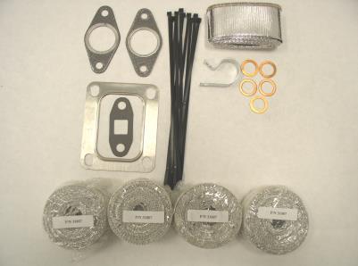
5 #15194 CAMARO TUNER KIT QTY P/N DESCRIPTION TUNER KIT# (COMPONENTS) Wastegate Ass'y, 9 Psi Adapter, Duo to Turbosmart BOV Turbosmart Pb38 BOV Hardware Kit, Nuts/Bolts/Fittings Hardware Kit, Clamps Hardware Kit, Hoses Hardware Kit, Gaskets Tube Ass'y, Intrclr to T-body Coolant Reservoir, Camaro Tube Ass'y, Cat to Turbo Tube Ass'y, Cat to Turbo Tube Ass'y, Cat to Turbo Tube Ass'y, Exh. Downpipe Tube Ass'y, Exh. Downpipe Tube Ass'y, Exh. Downpipe Tube Ass'y, Exh. Downpipe Tube Ass'y, Intrclr to T-body Coolant Pipe, Upper, 1.38" Coolant Pipe, Lower, " Bracket, Cat to Turbo Bracket, Cat to Turbo Bracket, Cat to Turbo Bracket, Cat to Turbo Bracket, Turbo Downpipe Bracket, Turbo Downpipe Tube Ass'y, P.S. Waste Dump Tube Ass'y, D.S. Waste Dump Instruction packet, Stickers Intercooler Assembly, 2010 HARDWARE KIT# (NUTS/BOLTS/FITTINGS) -See page 3 for assembly components Tuner Kit Notes: 1. The Turbonetics turbocharger of your choice is to be purchased along with this tuner kit. 2. This kit requires additional parts (primarily fuel system and air inlet) in order to complete the installation. 3. Some sections of this turbocharger kit instruction manual will not be applicable. 4. This kit is not legal for use in California and does not have a CARB EO#. HARDWARE KIT# (CLAMPS) PARTS LIST: Clamp V-Band Hose Clamp, T-Bolt Band Hose Clamp, Worm Drive, # Hose Clamp, Worm Drive, 5/8" Hose Clamp, Worm Drive, # Hose Clamp ½ Pinch Hose Clamp 3/8 Pinch Loop Clamp, 1.38",.28 hole Hose Clamp, Worm Drive, # Hose Clamp, Worm Drive, # Exhaust Band Clamp, 2.50" Exhaust Band Clamp, 3.00 HARDWARE KIT #11561 (HOSES) PARTS LIST: Oil Supply Hose Assy, -4X 36" Water Supply Hose, 52" Hose, Silicon 45º Elbow, Ø Hose, Silicone 90º Elbow, Ø Hose, Silicone 45º Elbow, Ø Silicone Hose Coupling, Hose, Silicone 3-4" Increaser 15' BK Silicone Vac. Hose, 5/32 2' BK Silicone Vac. Hose, 1/4 1.5' Hose, Oil Drain, 5/8" I.D Hose Coupler, Coolant, 1.5" ID 2' Hose, J30R9 1/2" I.D Breather hose, from Camaro auto Hose Coupler, Coolant, 1.38" ID HARDWARE KIT #11562 (GASKETS) PARTS LIST: Gasket, Deltagate/Evo Gasket, Oil Drain, T3/T Gasket, Turbine Inlet, T4 20' Heat Wrap, 1.0" Diam. 2' Safety Wire, S.S..035" Washer, Crush - 16mm O-ring, Duo Gate Heat Wrap, 2 x25 Roll Tie, Heat Wrap Cable Ties, Nylon - 8 1/2" O-ring, Viton OD 60203_revC Page 5 of 36


6 P/N P/N P/N P/N P/N P/N P/N P/N P/N P/N BB P/N P/N _revC Page 6 of 36


7 P/N P/N P/N P/N P/N P/N P/N P/N P/N P/N P/N P/N _revC Page 7 of 36


8 P/N P/N P/N P/N P/N P/N P/N P/N P/N P/N P/N P/N _revC Page 8 of 36


.")
9 PREPARING THE VEHICLE FOR TURBO KIT INSTALLTION 1. Jack the vehicle up to a workable height. Secure the vehicle with jack stands. 2. Remove the negative cable from the battery terminal. 3. Drain the engine coolant. FRONT END PREPARATION 1. Remove the six plastic clips and two 10mm headed screws from the top of the core support. 2. Remove the three T20 torx headed screws securing both front fender well liners. 3. Remove the two plastic fasteners securing the plastic fender liner to the fender well. 4. Remove the two 10mm headed screws on the underside. 5. Remove the three 10mm headed screws behind headlight and one on the fender edge (both sides). Remove 4 Screws (each side) 6. Unplug the light harness on passenger side. Remove the front bumper cover _revC Page 9 of 36


10 7. Remove 6 bolts securing the metal bumper (3 each side). 8. Remove 6 plastic clips and ambient air temp sensor from air guides and remove air guides. 9. Remove 4 bolts holding headlights. Unplug and remove headlights. ENGINE COMPARTMENT PREPARATION 1. Remove the plastic engine cover and the air filter top cover and set aside for later use. 2. Remove the remaining air filter housing and all ducting up to the throttle body. Set aside the two nuts for later use. 3. Remove the windshield washer reservoir from the vehicle. Set aside the w/w pump for later use. 4. Remove the coolant reservoir and upper and lower radiator hoses. 5. Remove the cover and the power cable from the fuse box on the passenger side. 6. Release the four clips and lift the fuse panel out of the way. 7. Remove the bolt holding the fuse box lower. 8. Slide the fuse box towards the rear of the vehicle approximately 2 to align with the hole in the tray. 9. Use factory bolt with the supplied flat washer and ny-lock nut to hold box in new location. 10. Replace the fuse panel and cover _revC Page 10 of 36


11 11. Disconnect the AC pressure sensor harness. Remove the sensor and O-ring. The shrader valve inside the AC line will prevent refrigerant from escaping. Install the supplied cap over the port. 12. Install the supplied a/c fitting into the quick connect adapter. Install the o-ring removed from the vehicle onto the small end of the a/c fitting. Install the pressure sensor onto the small end of the a/c fitting. Remove the plastic cap from the upper a/c tube and attach sensor. Plug in sensor as shown. Supplied o-ring Install o-ring FUEL INJECTOR INSTALLATION 1. Unplug the electrical connectors from all 8 of the fuel injectors. 2. With the engine cool, remove the gas cap to bleed any residual pressure. Bleed the pressurized fuel into a container by depressing the schrader valve located in the front of the driver side fuel rail. NOTE: Fuel is under pressure! Eye protection is a must. 3. Remove the 2 bolts securing each fuel rail. 4. Pull the fuel rail with injectors away from the engine. Hold them over the container. NOTE: Fuel may squirt out of the engine as the injectors are removed. 5. Using a flathead screw driver, metal injector clip off of the metal retainer on the fuel rail. Remove each fuel injector. Drain any fuel out of the rail and into the container. 6. Install the metal clips onto the supplied fuel injectors. 7. Lubricate the o-rings on the new injectors using motor oil or similar lubricant. Install the new injectors onto the fuel rail. Be sure that the plugs will face away from the engine. Seat the injectors into the cylinder head. Be sure they are properly seated in order to avoid any leaks. Re-secure the fuel rail with the original bolts. Plug the harness back on all the injectors _revC Page 11 of 36
 into the rear hose. Install the ¾ Tee (P/N 21652) into the forward hose. Secure using the supplied hose clamps (PN 30817). TURBO OIL DRAIN INSTALLATION 1.")

12 TURBO WATER LINE INSTALLATION 1. Locate the two heater hoses where they attach to the thermostat housing on the passenger side of the engine. Cut as shown. 2. Install the 5/8 Tee (P/N 21651) into the rear hose. Install the ¾ Tee (P/N 21652) into the forward hose. Secure using the supplied hose clamps (PN 30817). TURBO OIL DRAIN INSTALLATION 1. Drill an 1/8 hole in the oil pan approximately 2.5 up from the bottom as shown. Enlarge the hole to 9/16 using a drill packed with grease to absorb the metal chips. 2. Liberally grease the included tap (30809). Use it to tap the hole in the oil pan. The tap is tapered so check the hole with the included 3/8 NPT fitting before using more than half the threads on tap. Warning: Threading the tap all the way in will result in a hole that is too large and leaks oil! 3. Using thread sealant, coat the threads of the 3/8 NPT fitting and install it into the oil pan. 4. Drain the rest of the oil from the engine. 5. Thread the ½ NPT x ½ barb oil drain fitting (31286) into the supplied 45º oil drain flange (21956) with thread sealant. Install the oil drain flange onto the turbo using the supplied gasket so that the fitting points towards the turbine housing. 6. Cut the supplied 1/2 hose (31290) to a length of 22. Slide it over the oil drain fitting on turbo and secure with pinch clamp (31287) _revC Page 12 of 36


13 7. Install 12 of heat shielding over the oil drain hose and secure with zip ties. BATTERY CABLE / OIL FEED LINE INSTALLATION 1. Remove the bolt holding the battery cable to the terminal and replace it with the supplied nut. 2. Remove the power terminal from the driver side fender well and secure it to provide the most battery cable slack. 3. Remove the accessory belt from the alternator. 4. Remove the battery cable from the alternator and lower alternator out of mount. 5. Remove the socket head oil galley plug from the side of the engine block. 6. Using thread sealant, attach the 1/8 NPT to -4 90º fitting to the M16 adapter. Using engine oil on the o-ring, install the M16 adapter into the engine. Tighten both fittings and point the -4 fitting down and toward the rear of the vehicle as shown _revC Page 13 of 36


14 7. Install and tighten the -4 oil line (with heat shielding) to the fitting as shown, leaving the other end disconnected. 8. Replace the alternator and belt and reposition alternator cable to allow as much room as possible for the exhaust system. 9. Attach heat wrap to all alternator wiring, spark plug wires, a/c line and power steering hose as shown. Slit heat wrap as needed and secure with cable ties. 10. Secure the a/c line and battery cable as close to fender well as possible. EXHAUST PIPE REMOVAL 1. Loosen the lower part of the rear valance panel (black panel beneath the rear bumper that the tail pipes protrude through _revC Page 14 of 36


.")

15 2. Loosen the two nuts on each of the exhaust clamps connecting the cats to the cat back exhaust and slide passenger side back and driver side forward. 3. Remove the four bolts securing the brace and the remove the cat back exhaust. 4. Disconnect the oxygen sensors on the driver side catalytic converter (cat). 5. Loosen the two nuts securing each cat to the exhaust manifold. Remove the driver side cat. Leave the passenger side cat loose but in place. 6. Remove the alignment boss (twist or grind off) from the passenger side cat and smooth any burrs. Grind off boss 60203_revC Page 15 of 36
 to the cat to turbo #3 pipe (22127) flange using two M10-1.")


16 TURBOCHARGER INSTALLATION 1. Loosely attach the cat to turbo #3 bracket (22141) to the cat to turbo #3 pipe (22127) flange using two M x40mm bolts and flat washers as shown. Install the two M x42mm studs into the remaining two holes in the turbo flange. Use the supplied exhaust wrap to insulate the pipe and secure with the supplied exhaust ties 2. Remove the nut from the alternator bracket and attach the cat to turbo #3 bracket using the factory nut. M x 42 Studs M x 40 Bolts & Flat Washers Remove and replace nut 3. Remove the bolt from the engine behind the alternator (has small ground wire) and attach cat to turbo #2-3 bracket (22140) using the factory bolt in the lower location and the supplied M10 x 50mm bolt, lock washer and.8 spacer. Loosely install a 2.5 clamp over the pipe and the bracket..8 spacer Factory bolt Supplied bolt, bracket and spacer 4. Place the cat to turbo #2 pipe (22126) into the space between the driver side exhaust manifold and the steering shaft and insert it into the open end of cat to turbo #3 pipe _revC Page 16 of 36
 to the boss on the engine block behind the")


17 To Turbo Heat wrap this section 5. Attach cat to turbo #2 bracket (22139) to the boss on the engine block behind the exhaust manifold with the supplied M x 30mm bolt and lock washer. Loosely install a 2.5 clamp over the bracket. 6. Loosely re-install the driver side cat. 7. Using a banjo bolt (31155) and two crush washers (31156) connect one of the supplied braided water lines to the front of the turbo center housing. (There is better access at this time than after the turbo is installed.) 8. Place the supplied gasket onto the turbo mounting flange. Mount the turbo (guiding oil drain line under alternator) using four M nuts and lock washers. Installed water line 60203_revC Page 17 of 36
 and two crush washers (31156) connect the remaining braided water line to the back of the turbo center housing.")

18 9. Connect the oil drain line to the fitting previously installed in the oil pan and secure with a pinch clamp. 10. Using a banjo bolt (31155) and two crush washers (31156) connect the remaining braided water line to the back of the turbo center housing. Route both water lines down and across to the previously installed Tees in the coolant lines. 11. Thread the supplied 1/8 NPT x -4 90º fitting into the oil feed on the turbo. Slip heat sleeve over the oil feed line and attach the line to the turbo. TURBO EXHAUST INSTALLATION 1. Bend the forward transmission cooler lines (below a/c compressor pulley) down as far as possible. 2. Slide heat shield over the A/C clutch harness. 3. Bend the lower transmission cooler lines towards the transmission. 4. Using a pry bar, bend the A/C tubes against the A/C compressor _revC Page 18 of 36


19 5. Remove the two bolts from the rear of the A/C compressor. Install the supplied turbo downpipe 2-3 bracket (22142 for or for ) and re-install the A/C bolts. 6. Using the supplied exhaust wrap to insulate the Turbo downpipe #1 and #2 pipe. Secure with the exhaust ties. Exhaust tie 60203_revC Page 19 of 36
 into the space between the A/C compressor and the frame.")

 onto the original")

")
20 7. Install the turbo downpipe #2 pipe (22129 for or for ) into the space between the A/C compressor and the frame. The flared end should be facing the turbo as shown below. Loosely secure it with a 3 clamp. 8. Cut a 19 piece of 5/8 hose. Install an 8 piece of heat sleeve over hose as shown. Install the supplied 5/8 hose (with heat shielding) onto the original location where the upper radiator hose teed off to the bottom of the engine. Secure with a hose clamp. (This step is not required on models) 9. With a 3 clamp pre-installed, slide the turbo downpipe #1 pipe (22128) into the #2 pipe. Clamp it loosely onto the turbine housing outlet using a 3 v-band clamp (30242) _revC Page 20 of 36
 using the supplied M10-1.5 x 60mm bolt, washer, lock washer and nut. 12.")
 into the #3 pipe and loosely clamp using an additional 3 clamp. 14.")
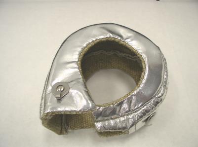
21 10. Install the supplied heat shield onto the turbine housing and secure with safety wire looped around the three metal hooks. 11. Remove the bolt in the rear passenger side of the transmission. Loosely install the turbo downpipe 2-3 bracket (22143) using the supplied M x 60mm bolt, washer, lock washer and nut. 12. Install the turbo downpipe #3 (22130 for or for ) into the #2 pipe and loosely secure it to the bracket using a 3 clamp. 13. Install the turbo downpipe #4 pipe (22131) into the #3 pipe and loosely clamp using an additional 3 clamp. 14. Remove the bolt from the driver side rear of the transmission and loosely install the cat to turbo #1 bracket (PN 22138). 15. Pre-position one 2 ½ clamp on each cat and two clamps (one for the bracket and one for the pipe joint) onto the cat to turbo #2 pipe. Slide the cat to turbo #1 pipe (22125) onto both cats and onto the #2 pipe _revC Page 21 of 36


22 Pre-position 2 ½ clamps Attach Bracket 16. Tighten the clamps just enough to be snug but still allow a little movement for alignment later WASTE GATE INSTALLATION NOTE: This vehicle is has dual waste gates and a relatively low boost setting (6.5 psi). In order to maintain boost control, the kit comes with smaller diameter valves installed in the waste gates. This flattens out the boost curve resulting in increased horsepower. The tuner kit maintains the larger valve in order to handle higher horsepower/boost applications. If you have any boost pressure stability issues, please contact Turbonetics for assistance. 1. Thread four M8 x 30mm studs (80860) into the waste gate flanges on the cat to turbo #1 pipe. 2. Thread 90º deg fittings into the waste gates with a small amount of sealant as shown. 3. Install two 1 ½ clamps ( ) over the female waste gate dump ports on the exhaust pipe and install the waste gate dump tubes loosely into the exhaust and orient for best fit _revC Page 22 of 36


23 4. Attach and tighten the base of the waste gates to the cat to turbo #1 pipe flanges using M8 nuts and lock washers. 5. Loosely bolt the dump tubes to the waste gates using gaskets, 5/16 x 1 bolts and lock washers. 6. Cut approximately 8 of 5/32 hose and attach it to the passenger side waste gate boost reference fitting. Cover with heat sleeve. Attach the supplied 3/16 T to the open end. 7. Cover approximately 38 of 5/32 hose with heat sleeve. Route the hose from driver side waste gate fitting, over the factory heat shield and attach it to the same 3/16 tee. Zip tie in place. 8. Cut approximately 80 of 5/32 hose. Cover 48 of hose with heat sleeve. Connect hose to 3/16 tee and route to the front of the car alongside the factory fuel lines. The open end of the hose will later be connected to the bottom of the intercooler. 9. Wrap exposed fuel lines with heat shielding as shown. 10. Cut the factory cat back exhaust 3 ½ behind crossover as shown and discard the crossover. Dress the cut ends _revC Page 23 of 36


 using a 1")
24 3 ½ Cut Here 11. Pre-install 2 ½ clamps onto the turbo exhaust. Slide the tail pipes through the rear valance. Line up the modified factory cat back and slide it forward into the turbo exhaust. Clamp loosely and reconnect all factory rubber hangers. 12. Check all pipes for proper clearance and tighten all clamps and brackets. RADIATOR HOSE INSTALLATION 1. Install the lower radiator tube (22135) using a 1 3/8 coupler on the bottom and a 1 ½ hose coupler on the top. Secure with four #24 clamps _revC Page 24 of 36
 3.")


25 2. Install the upper radiator tube (22134 for or for ) with two 1 3/8 couplers and #24 hose clamps. Connect the open end of the previously installed 5/8 hose to the upper radiator tube using a hose clamp. (Install ¼NPT plug to with thread sealant, for only) 3. Using thread sealant, install the supplied ¼ npt x 3/8 90º fitting and the 1/8 npt x ¼ 90º fitting into the bottom of the supplied reservoir so that they will both point towards the front of the vehicle. 4. Install the supplied radiator reservoir onto the two 6mm studs on the driver side fender well. Secure with the factory nuts removed with the air filter housing. 5. Trim and attach the 3/8 factory radiator surge hose to a 3/8 barbed fitting installed in the bottom of the reservoir. Attach the supplied ¼ hose to the remaining fitting and leave loose. 6. Install the factory radiator overflow tank cap and the windshield washer cap onto their respective locations on the reservoir. Clean recessed area with lacquer thinner and apply the supplied sticker _revC Page 25 of 36


26 7. Remove the windshield washer pump from the factory reservoir. Use the supplied loop clamp and 1/4 bolt to secure it as shown. Connect the factory windshield washer hose and the electrical plug to the top of the pump. Connect the pump inlet (bottom) to the previously installed ¼ hose from the reservoir. INTERCOOLER INSTALLATION 1. Bend the driver side sheet metal on the core support forward as shown. Thread two vibration dampeners (31160) into the two threaded holes below the hood latch _revC Page 26 of 36


27 2. Thread the supplied 1/8 npt to 5/32 hose fitting into the hole in the bottom of the intercooler. Thread a vibration dampener into long boss on bottom of intercooler and an M8 x 25mm stud into the short boss. 3. Install the bypass valve o-ring onto flange. Loosely attach the bypass valve to the intercooler. Test fit intercooler, clock bypass valve, and then tighten the set screws as shown BOV Adapter 4. Install the short end of the 2 ½ 45º compressor discharge sleeve onto the intercooler inlet. 5. Install the intercooler by sliding the inlet sleeve between the radiator and the core support and onto the compressor discharge elbow. Align the lower mounting studs with the lower core support slots. Mount the top of the intercooler to the vibration dampeners using M8 nuts and lock washers _revC Page 27 of 36


28 6. Mount the intercooler to the bottom of the core support as shown using large flat washers and the two M8 lock nuts. Connect the 5/32 silicone hose from the waste gates to the fitting on the intercooler using a zip tie. Supplied rubber washer under mounting boss and a M8 fender washer above and below core support. 7. Attach the factory air temperature sensor to the hole near the intercooler outlet. INTERCOOLER DUCTING INSTALLATION 1. Clamp the 3 4 step sleeve (30502) to the intercooler outlet using a #48 hose clamp. 2. Connect the intercooler to T-body #1 tube (22132) to the sleeve with a #64 hose clamp _revC Page 28 of 36

 using the supplied M4 screws. 5.")


29 3. Remove the Mass Air Flow (MAF) sensor from the factory air box lid. Maf sensor 4. Install the MAF into the supplied intercooler to T-body #2 tube (11563) using the supplied M4 screws. 5. Install the tube using two 4 sleeves and secure with #64 hose clamps. Connect the MAF harness to the MAF sensor. AIR INLET INSTALLATION 1. Install the supplied o-ring on the MAF block-off plate and attach it to the MAF boss on the air filter housing using the original fasteners _revC Page 29 of 36

 Attach the open end of the elbow to the compressor inlet. Orient for best fit and secure with #64 clamps.")

 electrical connector and hose and move out")
30 2. Do not remove the white pad from the air filter housing. Place the factory air filter onto the housing and secure by snapping on the supplied clamp as shown. 3. Install the 4 silicone elbow onto the air filter housing. (Lightly grease the elbow to aid installation.) Attach the open end of the elbow to the compressor inlet. Orient for best fit and secure with #64 clamps. 4. Use the supplied 1.5 tube to attach the bypass valve discharge to the air inlet elbow using the supplied º elbow. 5. Unplug the evap. purge solenoid (located on the front of the passenger side head) electrical connector and hose and move out of the way. Secure the heater hoses out of the way. 6. Disconnect the PCV hose from the intake manifold. Use a 1/4 drill bit to slightly enlarge the inside diameter of the plastic tube by hand turning the bit _revC Page 30 of 36


31 7. Clean the plastic, apply a small amount of sealant to the check valve and press it into the intake manifold. Remove excess sealant and reinstall the PCV hose. 8. Connect the valve cover breather to the air inlet elbow using the original breather tube and the supplied breather tube. Cut tubes as shown, heat the supplied 5/16 hose mender in an oven to 250ºF, and press the long plastic tubes onto the heated fitting. 9. Orient for best routing, protect with heat shield where it passes near the exhaust, and attach the plastic tube to the air inlet using the supplied pinch hose clamp _revC Page 31 of 36


. 2.")
32 10. Remove the vacuum hose from the brake booster reservoir. Using sealant, install the 1/16 npt to 3/16 barb fitting into the ½ barb x ½ barb x 1/16 female npt tee fitting. Clamp a 2 section of ½ hose to the tee using the supplied pinch clamp. Attach the tee to the factory vacuum hose using the original clamp. Attach the ½ hose to the brake booster reservoir and secure with pinch clamp. 11. Run 5/32 hose from the tee to the hose barb on the bypass valve. Secure away from the exhaust. RE-ASSEMBLY 1. Cut the stud off of the rear of the driver side headlight assembly where it would interfere with the inlet sleeve. Install the headlight. (Note: The headlight may still be adjusted after the stud is cut but range will be limited. If large changes in headlight adjustment are foreseen, leave stud as is and protect with a vacuum cap until after headlights are adjusted). 2. Install the front bumper and cover. 3. Install the engine cover. 4. Re-attach the rear valance body panel. CLEAN UP 1. Review these instructions to make sure that all fasteners, clamps & electrical connections have been installed and torqued correctly _revC Page 32 of 36
 to factory recommended levels.")
 unleaded fuel is required for proper engine performance and to reduce the possibility of internal engine damage from detonation. 5. Re-connect the battery.")
33 2. Check that all hose routings are free of any kinks or near any hot or abrasive surfaces that may cause wear over time. Adjust or reroute as necessary to provide adequate slack for engine movement. 3. Refill all fluids (oil, power steering, coolant and windshield washer) to factory recommended levels. The use of synthetic motor oil (with the factory recommended oil weight) is strongly recommended, as it will prolong the life of the turbocharger. 4. The use of premium octane (91+) unleaded fuel is required for proper engine performance and to reduce the possibility of internal engine damage from detonation. 5. Re-connect the battery. CARB EO, SPARK PLUG GAP, & FUEL DECAL 1. Included with each Turbonetics turbo kit, are adhesive backed decals with the CARB E.O number that is associated with this product, the spark plug gap spec, and the premium fuel required decal. Both the CARB E.O and spark plug gap spec decal is required to be adhered in the engine compartment that is visible and easily located by Smog Check and Service technicians. Turbonetics suggests cleaning and adhering the labels on the upper core support where the hood latch is located. CARB EO# Decal Spark Plug Gap Decal 2. Adhere the premium fuel required decal on the back side of the fuel door. Ensure surface is clean before adhering decal. Premium Fuel Required Decal 60203_revC Page 33 of 36


34 ECU RE-PROGRAMMING 1. Plug the included Diablosport up loader into the OBDII port located underneath the driver s side dash. 2. Turn the ignition to ON position, but do NOT start car. Read and agree to the directions stated on the boot-up screen. Touch YES to continue. Touch Tune Vehicle to begin _revC Page 34 of 36


35 3. Ensure the Key is in the RUN position as per the screen instructions, touch Continue to move on the next page. Next Touch the Advanced Tune button. 4. Next touch Install Standard Tune followed by selecting Turbonetics Performance Tune The programmer will now back up the Original calibration and install the custom one. Do not disconnect or power off vehicle during this process as this may cause serious ECU issues. *NOTE: Selecting Modify Tune is not suggested unless you are trying to correct a specific issue. 5. Start the vehicle and check for any oil or coolant leaks prior to a test drive. 6. Test drive the vehicle, check for oil/coolant leaks again, check all fluid levels and top off as necessary. If you are experiencing any issues of idling, bucking, running extremely rich, or poor performance, ensure that all hose clamps are tight and all hoses are installed properly and that there are no air leaks of any kind in the plumbing from turbo to intercooler to throttle body. If you need any support, our tech lines are 60203_revC Page 35 of 36
36 open Monday through Friday from 8am to 5pm at (805) , or go to our website at to our forums under Tech Support. CAMARO DRIVING NOTE: This vehicle is equipped with catalytic converters which take energy out of the exhaust in order to heat up. This slows the initial boost response until the CATs are warm. Subsequent full throttle performance is not as heavily affected. EMISSIONS NOTE: This vehicle is emissions legal only when the parts are installed as described in this instruction manual. Making changes to the kit or ECU programming voids the CARB exemption order making the vehicle illegal for use on California roads. NO FAULT / NO HASSLE WARRANTY PROGRAM: TURBONETICS will repair or replace, at our expense, any new TURBONETICS / Spearco products that fail, including products used in racing or competition applications, for a period of one year from the original date of purchase. All turbocharger and cartridge assemblies have a factory installed inline oil filtration device. This filter device must remain in place if any warranty is to be considered under the No-Fault / No-Hassle program. Electrical components that fail due to misuse are not covered under the No-Fault / No-Hassle Warranty Program. Warranty is limited to TURBONETICS products and does not include progressive or subsequential damage and does not cover removal or installation labor or associated parts. No warranty is made for any other claims for special, indirect or consequential damages including but not limited to component removal or installation equipment downtime, prospective profits or other economic loss. Warranty will not be granted for recurring damage, malfunction, or failure due to improper installation, misuse, unauthorized repair or alterations, or externally induced physical damage. Warranty is non-transferable and must be processed via the original purchaser from TURBONETICS. Remanufactured units, performance upgraded units, and O.E.M. replacement units are covered by a 90-day warranty or the O.E. warranty period. TURBONETICS highly recommends that the installation of mechanical or electrical parts be performed by trained professionals. Improperly installed products may lead to unsafe and unreliable conditions. RETURN POLICY: Only unused and complete merchandise may be accepted for return subject to inspection and acceptance by TURBONETICS. No goods will be accepted without prior return authorization from TURBONETICS. Call for approval and RGA (Returned Goods Authorization) tracking number. No returns will be accepted without an RGA tracking number. No returns will be accepted after ninety (90) days from the original shipping date from TURBONETICS unless approved. All approved returns are subject to a 15% restocking charge NO EXCEPTIONS. The original invoice must accompany the return. Accepted warehouse / distributor and open account returns will be issued credit only. RETURNED GOODS AUTHORIZATION TRACKING NUMBER: TURBONETICS will only accept product returns, repair orders / upgrades, and warranty requests that have been approved and are returned with a corresponding RGA (Returned Goods Authorization) tracking number. Contact TURBONETICS for approval and the RGA number. Write the RGA number clearly on the outside of the package and include it inside the package. This is very important in allowing us to properly identify and process your request. Failure to comply with this requirement will result in the delay of processing or the product being returned to you _revC Page 36 of 36
INSTALLATION INSTRUCTIONS TURBOCHARGER SYSTEM: 2010/2011 Chevrolet Camaro SS Automatic P/N 15193
 www.turboneticsinc.com INSTALLATION INSTRUCTIONS TURBOCHARGER SYSTEM: 2010/2011 Chevrolet Camaro SS Automatic P/N 15193 This turbocharger kit is emissions legal per CARB E.O.: D-99-7 Turbonetics, Inc.
INSTALLATION INSTRUCTIONS. Upgrade Front Intercooler BMW 335 Twin Turbo P/N 15179
 INSTALLATION INSTRUCTIONS Upgrade Front Intercooler 2007- BMW 335 Twin Turbo P/N 15179 Turbonetics, Inc. * 2255 Agate Court * Simi Valley, CA * 805-581-0333 * TurboneticsInc.com READ THIS FIRST: Study
Intercooler Upgrade Kit Kit p/n Mitsubishi Lancer EVO X
 INSTALLATION INSTRUCTIONS Intercooler Upgrade Kit Kit p/n 11647 Mitsubishi Lancer EVO X Turbonetics, Inc. * 2255 Agate Court * Simi Valley, CA * 805-581-0333 * TurboneticsInc.com READ THIS FIRST: Study
Intercooler Upgrade Kit
 INSTALLATION INSTRUCTIONS Intercooler Upgrade Kit 04-06 Ford 6.0L P/N 70057 99-03 Ford 7.3L P/N 70058 Turbonetics, Inc. * 14399 Princeton Avenue * Moorpark, CA * 805-581-0333 * TurboneticsInc.com READ
INSTALLATION INSTRUCTIONS. Upgrade Front Intercooler 2001 Early 2006 Chevrolet / GMC Duramax P/N 2-486
 INSTALLATION INSTRUCTIONS Upgrade Front Intercooler 2001 Early 2006 Chevrolet / GMC Duramax P/N 2-486 Turbonetics, Inc. * 2255 Agate Court * Simi Valley, CA * 805-581-0333 * TurboneticsInc.com READ THIS
Treadstone Performance Engineering Inc, Miami Fl
 INSTALLATION INSTRUCTIONS TURBOCHARGER SYSTEMS: 2007+ Nissan Sentra SER & Spec-V READ THIS FIRST: Study these instructions completely before proceeding. Engine and/or turbocharger damage may occur if any
03-04 Mach 1. Hellion Power Systems Mach 1 Kit Instructions
 Hellion Power Systems 03-04 Mach 1 Kit Instructions Part 1 Hellion recommends that the front suspension system be installed either by trained professionals or by 5.Remove rack bolts K-Member Installation
05-08 GT. Hellion Power Systems Mustang Kit Instructions
 Hellion Power Systems 05-08 Mustang Kit Instructions 1. Disconnect Battery 2. Drain Radiator, keep fluid for re-installation. 3. Remove air box and inlethoses. 6. Next, underneath, punch oil pan for turbo
99-04 GT. Hellion Power Systems Mustang GT Kit Instructions
 Hellion Power Systems 99-04 Mustang GT Kit Instructions Part 1 Hellion recommends that the front suspension system be installed either by trained professionals or by 5.Remove rack bolts K-Member Installation
BD TrackMaster S D o d g e H P C R Installation Instructions
 7 July 2016 PN#1045701, 1045702, 1045704 Dodge 6.7L TMS400 (I-00361) 1 BD TrackMaster S400 2008-2012 D o d g e H P C R Installation Instructions 1045701 2008-2009 Dodge 6.7L TMS400 1045702 2010-2012 Dodge
4 December 2017 PN# , , Dodge 6.7L Rumble B SXE (I-00400) 1. BD Rumble B SXE. D o d g e 6. 7 L H P C R Installation Instructions
 1. BD Rumble B SXE. D o d g e 6. 7 L H P C R Installation Instructions") 4 December 2017 PN#1045705, 1045706, 1045708 Dodge 6.7L Rumble B SXE (I-00400) 1 DOWNLOAD ENHANCED INSTALL MANUALS AT dieselperformance.com BD Rumble B SXE D o d g e 6. 7 L H P C R Installation Instructions
4 December 2017 PN#1045705, 1045706, 1045708 Dodge 6.7L Rumble B SXE (I-00400) 1 DOWNLOAD ENHANCED INSTALL MANUALS AT dieselperformance.com BD Rumble B SXE D o d g e 6. 7 L H P C R Installation Instructions
3 October 2016 PN# V Dodge Twin Turbo Kit (I-00274) ½ D o d g e 2 4 v I S B
 ½ D o d g e 2 4 v I S B") 3 October 2016 PN#1045320 24V Dodge Twin Turbo Kit (I-00274) 1 DOWNLOAD ENHANCED INSTALL MANUALS AT dieselperformance.com BD Twin Turbo Kit 1998½- 2 0 0 2 D o d g e 2 4 v I S B Part# 1045320 PLEASE READ
3 October 2016 PN#1045320 24V Dodge Twin Turbo Kit (I-00274) 1 DOWNLOAD ENHANCED INSTALL MANUALS AT dieselperformance.com BD Twin Turbo Kit 1998½- 2 0 0 2 D o d g e 2 4 v I S B Part# 1045320 PLEASE READ
4. Remove (4) 10mm and (1) 7mm bolt that holds fascia at front corners, on each side
 10mm and (1) 7mm bolt that holds fascia at front corners, on each side") 2010 Camaro LS3 1. Disconnect battery ground 2. Remove front wheels 3. Remove (5) push pins and (5) #20 torx screws on inner front wheel well liners and remove liners on each side 4. Remove (4) 10mm and
2010 Camaro LS3 1. Disconnect battery ground 2. Remove front wheels 3. Remove (5) push pins and (5) #20 torx screws on inner front wheel well liners and remove liners on each side 4. Remove (4) 10mm and
INSTALLATION INSTRUCTIONS. TURBOCHARGER SYSTEMS: 2003 / 2004 Nissan 350Z VQ35 3.5L V6 Engine, Manual Transmission Only
 INSTALLATION INSTRUCTIONS TURBOCHARGER SYSTEMS: 2003 / 2004 Nissan 350Z VQ35 3.5L V6 Engine, Manual Transmission Only P/N 15134 (No Catalytic Converter) P/N 15136 (With Catalytic Converter) P/N 15138 (No
Installation Manual v1.0: Aurora Plus Turbo Kit ( ) 5.9L Dodge. Please read all instructions before installation.
 5.9L Dodge. Please read all instructions before installation.") Installation Manual v1.0: Aurora Plus - 4000 Turbo Kit (2003-2007) 5.9L Dodge Please read all instructions before installation. Figure 1: Aurora Plus - 4000 Kit Contents 1 Figure 2: Aurora Plus Hardware
Installation Manual v1.0: Aurora Plus - 4000 Turbo Kit (2003-2007) 5.9L Dodge Please read all instructions before installation. Figure 1: Aurora Plus - 4000 Kit Contents 1 Figure 2: Aurora Plus Hardware
BD Twin Turbo Cobra Kit
 14 September 2017 1045780-94 Dodge Cobra Kit (I-00377) 1 BD Twin Turbo Cobra Kit 2003-2012 Dodge HPCR Machined BD turbochargers only BUILDERS KIT Installation reccomendations to aid asssembly Does not
Installation Manual v1.0: MST Turbo Kit ( ) 5.9L Dodge. Please read all instructions before installation.
 5.9L Dodge. Please read all instructions before installation.") Installation Manual v1.0: MST Turbo Kit (2003-2007) 5.9L Dodge Please read all instructions before installation. Figure 1: MST Kit Contents Figure 2: MST Hardware Kit Please make sure all of the components
Installation Manual v1.0: MST Turbo Kit (2003-2007) 5.9L Dodge Please read all instructions before installation. Figure 1: MST Kit Contents Figure 2: MST Hardware Kit Please make sure all of the components
Scion FR-S ZN6. GTX2867R Gen2 (Internal Wastegate) Installation Instructions GPP P/N #
 Installation Instructions GPP P/N #") TURBO KIT Scion FR-S ZN6 Subaru BRZ ZC6 GTX2867R Gen2 (Internal Wastegate) Installation Instructions GPP P/N # 11518000 Vehicle Type Chassis Code Engine Code Transmission Model Year Scion FR-S DBA-ZN6
TURBO KIT Scion FR-S ZN6 Subaru BRZ ZC6 GTX2867R Gen2 (Internal Wastegate) Installation Instructions GPP P/N # 11518000 Vehicle Type Chassis Code Engine Code Transmission Model Year Scion FR-S DBA-ZN6
96-04 tt. Hellion Power Systems Mustang Twin Turbo Kit Instructions
 96-04 tt Hellion Power Systems 1996-2004 Mustang Twin Turbo Kit Instructions 1. Disconnect battery and elevate front end of car on either Jack stands or a lift if available 2.Lock steering wheel and remove
Equipped with AEM Dryflow Filter No Oil Required! INSTALLATION INSTRUCTIONS PART NUMBER: DS (Plastic Intake Tube)
") Equipped with AEM Dryflow Filter No Oil Required! INSTALLATION INSTRUCTIONS PART NUMBER:21-8126DS (Plastic Intake Tube) 2011-2014 Ford F150 V6 3.5L ECOBOOST C.A.R.B. E.O. D-670-19 AEM Induction Systems
Equipped with AEM Dryflow Filter No Oil Required! INSTALLATION INSTRUCTIONS PART NUMBER:21-8126DS (Plastic Intake Tube) 2011-2014 Ford F150 V6 3.5L ECOBOOST C.A.R.B. E.O. D-670-19 AEM Induction Systems
INSTALLATION INSTRUCTIONS. TURBOCHARGER SYSTEMS: 2003 / 2004 Nissan 350Z VQ35 3.5L V6 Engine, Manual Transmission Only
 INSTALLATION INSTRUCTIONS TURBOCHARGER SYSTEMS: 2003 / 2004 Nissan 350Z VQ35 3.5L V6 Engine, Manual Transmission Only P/N 15134 (No Catalytic Converter) P/N 15136 (With Catalytic Converter) P/N 15138 (No
Procharger Stage II Intercooled Supercharger System (11-14 GT)
") Procharger Stage II Intercooled Supercharger System (11-14 GT) Installation Time: Approximately one day. Installed on 2012 Mustang GT 5.0/Manual Required Tools 3/8 Socket Set (Standard and Metric) 1/2
Procharger Stage II Intercooled Supercharger System (11-14 GT) Installation Time: Approximately one day. Installed on 2012 Mustang GT 5.0/Manual Required Tools 3/8 Socket Set (Standard and Metric) 1/2
PART NUMBER:
 Equipped with AEM Dryflow Filter No Oil Required! INSTALLATION INSTRUCTIONS PART NUMBER: 21-8020 2006 PONTIAC GTO V8-6.0L SEE * NOTE 2005 PONTIAC GTO V8-6.0L C.A.R.B. E.O. # D-670-2 * NOTE: Legal in California
INSTALL MANUAL D o d g e 1 2 v 6 B T A PLEASE READ ALL INSTRUCTIONS BEFORE INSTALLATION.
 PN#1045310 12V Dodge Twin Turbo Kit (I-00273) 1 INSTALL MANUAL BD Twin Turbo Kit 1994-1 9 9 8 D o d g e 1 2 v 6 B T A Part# 1045310 PLEASE READ ALL INSTRUCTIONS BEFORE INSTALLATION. * Picture as shown
IAG Competition Series Air / Oil Separator (AOS) For 2017 STI
 For 2017 STI") P IAG Competition Series Air / Oil Separator (AOS) For 2017 STI Part# IAG-ENG-7251 Tools Required: Ratchet, torque wrench, extensions, needle nose pliers, hose cutter, snips/scissors, flat head screw driver,
P IAG Competition Series Air / Oil Separator (AOS) For 2017 STI Part# IAG-ENG-7251 Tools Required: Ratchet, torque wrench, extensions, needle nose pliers, hose cutter, snips/scissors, flat head screw driver,
INSTALLATION INSTRUCTIONS. TURBOCHARGER SYSTEMS: Infiniti G35 VQ35 3.5L V6 Engine, Automatic Transmission Only
 INSTALLATION INSTRUCTIONS TURBOCHARGER SYSTEMS: 2003-2005 Infiniti G35 VQ35 3.5L V6 Engine, Automatic Transmission Only P/N 15165 (No Catalytic Converter) P/N 15166 (With Catalytic Converter) P/N 15165-T
Wrenches: ⅞, 8mm, 10mm, 13mm, 19mm P. allen, Other: Electrical Tape
 IAG Street Series Air / Oil Separator (AOS) For 2008-14 STI Part# IAG-ENG-7100 Tools Required: Ratchet, torque wrench, extensions, needle nose pliers, hose cutter, snips/scissors, flat head screw driver,
3.4L V6 SUPERCHARGER 7 TH INJECTOR KIT
 Part Number: 00602-17620-260 00602-17620-261 00602-17620-263 00602-17620-264 00602-17620-274 00602-17620-275 00602-17620-276 Section I Installation Preparation Kit Contents Item # Quantity Reqd. Description
PART NUMBER: MINI Cooper S L4-1.6L SEE * NOTE
 Equipped with AEM Dryflow Filter No Oil Required! INSTALLATION INSTRUCTIONS PART NUMBER: 21-699 2007-2010 MINI Cooper S L4-1.6L SEE * NOTE * NOTE: Legal in California only for racing vehicles which may
BD 6.7L Super B Special Turbo Kit For L Dodge -- I n s t a l l a t i o n I n s t r u c t i o n s -- PN#
 28 January 2014 1045140 6.7L Super B Special Turbo Installation (I-00266) 1 BD 6.7L Super B Special Turbo Kit For 2007.5-2012 6.7L Dodge -- I n s t a l l a t i o n I n s t r u c t i o n s -- PN# 1045140
JBR MAZDASPEED
 Page1 james Barone Racing Aftermarket Parts and Accessories JBR 2007 2009 MAZDASPEED 3 Front Mount Intercooler Piping Kit Installation Instructions for TR8 Intercooler Tooling: o Jack, Jack Stands, Ramps
BD Twin Turbo Cobra Kit
 17 March 2017 1045780-94 Dodge Cobra Kit (I-00377) 1 BD Twin Turbo Cobra Kit 2003-2012 Dodge HPCR Machined BD turbochargers only BUILDERS KIT Installation reccomendations to aid asssembly Does not include
Part# PLEASE READ ALL INSTRUCTIONS BEFORE INSTALLATION.
 16 November 2009 HPCR Dodge Twin Turbo Kit #1045430 1 BD Twin Turbo R700 Kit 2003-2007 Dodge HPCR ISBe Installation Instructions Part# 1045430 PLEASE READ ALL INSTRUCTIONS BEFORE INSTALLATION. UNLESS AN
03-04 Cobra. Hellion Power Systems Mustang Cobra Kit Instructions
 Hellion Power Systems 03-04 Mustang Cobra Kit Instructions NECESSARY PARTS REQUIRED FOR INSTALLATION Necessary: 03-04 Cobra hellion Kit ONLY 99-01 Alternator #YR3210346AA Alternator Bracket #XR3Z-10153-AB
INSTALLATION INSTRUCTIONS. TURBOCHARGER SYSTEMS: Nissan Spec V. P/N (No Catalytic Converter)
") INSTALLATION INSTRUCTIONS TURBOCHARGER SYSTEMS: 2002-2003 Nissan Spec V P/N 15173 (No Catalytic Converter) Turbonetics, Inc. * 2255 Agate Court * Simi Valley, CA * 805-581-0333 * TurboneticsInc.com READ
INSTALLATION INSTRUCTIONS TURBOCHARGER SYSTEMS: 2002-2003 Nissan Spec V P/N 15173 (No Catalytic Converter) Turbonetics, Inc. * 2255 Agate Court * Simi Valley, CA * 805-581-0333 * TurboneticsInc.com READ
BD Cobra Compound Turbo
 3 July 2018 1045780-98 Dodge Cobra Turbo Kit (I-00377) 1 DOWNLOAD COLOR INSTALL MANUALS AT www.dieselperformance.com BD Cobra Compound Turbo 2003-2018 Dodge Cummins Cobra 76 Cobra 80 Cobra 86 Cobra 88
Corvette Stage X Twin Turbo Installation. Please read the entire instructions as we ve made many changes.
 Corvette Stage X Twin Turbo Installation Please read the entire instructions as we ve made many changes. Disconnect battery. Remove plastic fuel rail covers over the valve cover. Remove Air Box in front
TURBOCHARGER L INSTALLATION GUIDE
 1 TURBOCHARGER INSTALLATION GUIDE TABLE OF CONTENTS Chapter Page 1 Intake and Cooling System Preparation 04 2 Intake Plenum and Manifold 08 3 Turbocharger Lubrication 11 4 Fuel Injectors 13 5 Re-installing
INSTALLATION INSTRUCTIONS PART NUMBER:
 Equipped with AEM Dryflow Filter No Oil Required! INSTALLATION INSTRUCTIONS PART NUMBER: 21-488 2006-2008 MAZDA 3 L4 2.3L SEE * NOTE 2004-2008 MAZDA 3 L4 2.0L SEE * NOTE 2004-2005 MAZDA 3 L4 2.3L C.A.R.B.
TURBO KIT INSTRUCTIONS
 Revision 12/20/10 TURBO KIT INSTRUCTIONS This turbo kit consists of the necessary parts to upgrade or add a turbo to your 22R/RE/RET. This kit may require some fabrication to address your particular application
Always wear safety glasses when working on your vehicle.
 90-93 MAZDA MIATA SUPERCHARGER KIT The KraftWerks 90-93 Mazda Miata Supercharger Kit was designed for easy installation. Competent mechanics with the appropriate tools will find the process to be relatively
BD 6.7L Super B Special Turbo Kit For L Dodge -- I n s t a l l a t i o n I n s t r u c t i o n s -- PN#
 26 September 2012 1045140 6.7L Super B Special Turbo Installation 1 BD 6.7L Super B Special Turbo Kit For 2007.5-2012 6.7L Dodge -- I n s t a l l a t i o n I n s t r u c t i o n s -- PN# 1045140 PLEASE
INSTALLATION INSTRUCTIONS
 Equipped with AEM Dryflow Filter No Oil Required! INSTALLATION INSTRUCTIONS PART NUMBER: 21-8304 1991-1995 JEEP Wrangler L4-2.5L C.A.R.B. E.O. # D-670 * NOTE: Legal in California only for racing vehicles
Equipped with AEM Dryflow Filter No Oil Required! INSTALLATION INSTRUCTIONS PART NUMBER:
 Equipped with AEM Dryflow Filter No Oil Required! INSTALLATION INSTRUCTIONS PART NUMBER:21-8125 2011-2012 Ford F150 V8 5.0L * NOTE: Legal in California only for racing vehicles which may never be used
8 Zip Tie Zip Tie 1 Union Fitting 1 ½ ½ Union Reducer Fitting Union 1 5/8 ½ (For Plastic Intake Manifold Vehicles)
") P IAG Street Series Air / Oil Separator (AOS) For 2017 STI Part# IAG-ENG-7151 Tools Required: Ratchet, torque wrench, extensions, needle nose pliers, hose cutter, snips/scissors, flat head screw driver,
P IAG Street Series Air / Oil Separator (AOS) For 2017 STI Part# IAG-ENG-7151 Tools Required: Ratchet, torque wrench, extensions, needle nose pliers, hose cutter, snips/scissors, flat head screw driver,
DODGE DART 1.4L I-4 C.A.R.B. E.O. # D
 Equipped with AEM Dryflow Filter No Oil Required! INSTALLATION INSTRUCTIONS PART NUMBER: 21-722C (Gun Metal Grey Finish) 21-722P (Vacuum Metalized Chrome - VMC) 2013-2014 DODGE DART 1.4L I-4 C.A.R.B. E.O.
Installation Instructions
 Approx. Install Time 3Hrs 00Min Installation Instructions Vehicle Application Year: 2013-2017 Make: Ram Model: 2500/3500 Diesel Engine: 6.7L Cummins Tools Required 7mm, 8mm, 10mm,& 13mm Wrench & Socket
INSTALLATION INSTRUCTIONS PART NUMBER:
 Equipped with AEM Dryflow Filter No Oil Required! INSTALLATION INSTRUCTIONS PART NUMBER: 21-469B (Blue Finish) 21-469C (Gun Metal Grey Finish) 21-469P (Vacuum Metalized Chrome-VMC) 21-469R (Red Finish)
IAG Competition Series Air / Oil Separator (AOS) For WRX
 For WRX") P IAG Competition Series Air / Oil Separator (AOS) For 2015-16 WRX Part# IAG-ENG-7252 Tools Required: Ratchet, torque wrench, extensions, needle nose pliers, hose cutter, snips/scissors, flat head screw
P IAG Competition Series Air / Oil Separator (AOS) For 2015-16 WRX Part# IAG-ENG-7252 Tools Required: Ratchet, torque wrench, extensions, needle nose pliers, hose cutter, snips/scissors, flat head screw
Included parts: 1 - BorgWarner SX-E Turbocharger 1 - SX-E 90-Degree Compressor Outlet Elbow 1 - HSM Cast Exhaust Manifold 1 - HSM Downpipe
 TROUBLESHOOTING: Please read and understand all installation instructions before proceeding with the installation. If you have questions during the installation of this product, please email H&S Motorsports
Always use fuel with a minimum octane rating of 93 (R+M)/2. (Equivalent to 98 RON).
/2. (Equivalent to 98 RON).") Before Commencing Installation Verify that you have all necessary tools as listed. Clean all air ducting prior to commencing installation. The sequence of installation of each part is very important. It
Before Commencing Installation Verify that you have all necessary tools as listed. Clean all air ducting prior to commencing installation. The sequence of installation of each part is very important. It
Includes: 1. High Flow Turbo Up-Pipe 1. J-Hook Block Off / Coolant Reroute 1. Coolant Hose 1. EGR Valve Block Off Plate 2. Hose Clamps 4.
 Includes: 1. High Flow Turbo Up-Pipe 1. J-Hook Block Off / Coolant Reroute 1. Coolant Hose 1. EGR Valve Block Off Plate 2. Hose Clamps 4. Bolts & Nuts WARNING: This product is not legal for sale or use
Instant Chat off the main page of Or simply call our tech team at
 FRONT MOUNT INTERCOOLER 2015+ WRX 2017-07-07 Thank you for purchasing this PERRIN product for your car! Installation of this product should only be performed by persons experienced with installation of
SLP Camaro ZL1 STAGE 3 (650 HP)
") SLP - 2012 Camaro ZL1 STAGE 3 (650 HP) PART #26002 PACKING LIST Before installation, use this check list to make sure all necessary parts have been included. ITEM QTY CHECK PART NUMBER DESCRIPTION 1. 1
SLP - 2012 Camaro ZL1 STAGE 3 (650 HP) PART #26002 PACKING LIST Before installation, use this check list to make sure all necessary parts have been included. ITEM QTY CHECK PART NUMBER DESCRIPTION 1. 1
DODGE SRT-4 PART NUMBER P (with Turbo Toys) P (without Turbo Toys) P (Stage 2 to Stage 3R Upgrade Kit)
 P (without Turbo Toys) P (Stage 2 to Stage 3R Upgrade Kit)") INFORMATION SHEET Stage 3R Turbo Upgrade Kit Components (1) Stage 3R PCM (4) 682 cc/min Fuel Injectors* (1) 3.0 bar MAP Sensor* (1) 3.0 bar TIP Sensor* (1) Block-off Connector for PCM (1) Mopar TD05HR
INFORMATION SHEET Stage 3R Turbo Upgrade Kit Components (1) Stage 3R PCM (4) 682 cc/min Fuel Injectors* (1) 3.0 bar MAP Sensor* (1) 3.0 bar TIP Sensor* (1) Block-off Connector for PCM (1) Mopar TD05HR
18SP680Rev3 EPA04 MBE 4000 Car Hauler Low Pressure Fuel Lines
 8SP680Rev3 EPA04 MBE 4000 Car Hauler Low Pressure Fuel Lines KIT DESCRIPTION These service kits include all necessary parts to replace the low pressure fuel lines between the fuel filter housing and fuel
Includes: 1. J-hook Block Off / Coolant Reroute 1. Coolant Hose 1. Turbocharger Up Pipe Block Off Disc 2. Hose clamps
 Includes: 1. J-hook Block Off / Coolant Reroute 1. Coolant Hose 1. Turbocharger Up Pipe Block Off Disc 2. Hose clamps WARNING: This product is not legal for sale or use on pollution controlled vehicles
INSTRUCTIONS PART NUMBER:
 Equipped with AEM Dryflow Filter No Oil Required! INSTALLATION INSTRUCTIONS PART NUMBER: 21-477 2006-2007 SUBARU Impreza WRX H4 2.5L Turbo C.A.R.B. E.O. # D-670-15 2004-2007 SUBARU Impreza WRX STi H4 2.5L
IAG Street Series Air / Oil Separator (AOS) For WRX & WRX STI
 For WRX & WRX STI") IAG Street Series Air / Oil Separator (AOS) For 2006-07 WRX & 2004-07 WRX STI Part# IAG-ENG-7100 Tools Required: Ratchet, torque wrench, extensions, needle nose pliers, hose cutter, snips/scissors, flat
IAG Street Series Air / Oil Separator (AOS) For 2006-07 WRX & 2004-07 WRX STI Part# IAG-ENG-7100 Tools Required: Ratchet, torque wrench, extensions, needle nose pliers, hose cutter, snips/scissors, flat
IAG Street Series Air / Oil Separator (AOS) For 2017 WRX
 For 2017 WRX") P IAG Street Series Air / Oil Separator (AOS) For 2017 WRX Part# IAG-ENG-7152 Tools Required: Ratchet, torque wrench, extensions, needle nose pliers, hose cutter, snips/scissors, flathead screwdriver,
P IAG Street Series Air / Oil Separator (AOS) For 2017 WRX Part# IAG-ENG-7152 Tools Required: Ratchet, torque wrench, extensions, needle nose pliers, hose cutter, snips/scissors, flathead screwdriver,
INSTALLATION INSTRUCTIONS
 Equipped with AEM Dryflow Filter No Oil Required! INSTALLATION INSTRUCTIONS PART NUMBER: 21-9034 YEAR MAKE MODEL Engine Info 2006-2007 CHEVROLET 2500HD Classic V8-6.6L DSL C.A.R.B. E.O. D-670-13 2006-2007
COLD AIR INTAKE SYSTEM
 COLD AIR INTAKE SYSTEM Installation Instructions for: Part Number 21-491 2005-2008 Mazda 6i 2.3L NON-PZEV Do not install a bypass valve on this intake system! ADVANCED ENGINE MANAGEMENT INC. 2205 126 TH
Instant Chat off the main page of Or simply call our tech team at
 FRONT MOUNT INTERCOOLER 2008-13 STI 2014-04- 08 Thank you for purchasing this PERRIN product for your car! Installation of this product should only be performed by persons experienced with installation
IAG Street Series Air / Oil Separator (AOS) For WRX
 For WRX") P IAG Street Series Air / Oil Separator (AOS) For 2015-16 WRX Part# IAG-ENG-7152 Tools Required: Ratchet, torque wrench, extensions, needle nose pliers, hose cutter, snips/scissors, flat head screw driver,
P IAG Street Series Air / Oil Separator (AOS) For 2015-16 WRX Part# IAG-ENG-7152 Tools Required: Ratchet, torque wrench, extensions, needle nose pliers, hose cutter, snips/scissors, flat head screw driver,
INSTALLATION INSTRUCTIONS
 Equipped with AEM Dryflow Filter No Oil Required! INSTALLATION INSTRUCTIONS PART NUMBER: 21-696 2009-2010 DODGE Challenger V6-3.5L SEE * NOTE * NOTE: Legal in California only for racing vehicles which
IAG Air / Oil Separator (AOS) For STi
 For STi") IAG Air / Oil Separator (AOS) For 2008-14 STi Part# IAG-ENG-7000 Tools Required: Ratchet, torque wrench, extensions, needle nose pliers, hose cutter, snips/scissors Sockets: 10mm, 12mm 13mm Wrenches: 10mm,
IAG Air / Oil Separator (AOS) For 2008-14 STi Part# IAG-ENG-7000 Tools Required: Ratchet, torque wrench, extensions, needle nose pliers, hose cutter, snips/scissors Sockets: 10mm, 12mm 13mm Wrenches: 10mm,
Instant Chat off the main page of Or simply call our tech team at
 02-07 WRX/STI Air Oil Separator for Top Mounted Intercooler Setups 2013-02- 27 Thank you for purchasing this PERRIN product for your car! Installation of this product should only be performed by persons
INSTALLATION INSTRUCTIONS
 Equipped with AEM Dryflow Filter No Oil Required! INSTALLATION INSTRUCTIONS PART NUMBER: 21-8203 2003-2005 DODGE RAM 1500 Pickup V8-5.7L C.A.R.B. E.O. # D-670 2003-2005 DODGE RAM 2500 Pickup V8-5.7L C.A.R.B.
Dodge 5.9L Cummins 24v ISBe
 15 December 2011 Part # 1045160 Killer B Dodge 2003-07 - 1 - BD Killer B Single Turbo 2003-2007 Dodge 5.9L Cummins 24v ISBe Part #1045160 PLEASE READ ALL INSTRUCTIONS BEFORE INSTALLATION. UNLESS AN EO#
Equipped with AEM Dryflow Filter No Oil Required! INSTALLATION INSTRUCTIONS PART NUMBER:
 Equipped with AEM Dryflow Filter No Oil Required! INSTALLATION INSTRUCTIONS PART NUMBER: 21-9032 Year Make Model Engine Info CARB E.O. # 2012 Chevrolet Silverado 2500HD/3500 HD V8-6.6L DSL D-670-13 2012
INSTALLATION INSTRUCTIONS
 Equipped with AEM Dryflow Filter No Oil Required! INSTALLATION INSTRUCTIONS PART NUMBER:21-8402 1999-2004 TOYOTA Tacoma V6-3.4L C.A.R.B. E.O. # D-670 1999-2002 TOYOTA 4Runner V6-3.4L C.A.R.B. E.O. # D-670
INSTALLATION INSTRUCTIONS: P/N: / D
 INSTALLATION INSTRUCTIONS: P/N: 75-5104 / 75-5104D 15461 SLOVER AVE., FONTANA, CA 92337 PH: 909.947.0015, FAX: 909.947.0603 WWW.SBFILTERS.COM Thank You! for purchasing your new S&B Filters intake kit.
2017+ L5P Duramax 3 ½ Down Pipe & EGR Fix Kit
 2017+ L5P Duramax 3 ½ Down Pipe & EGR Fix Kit Covers installation of PN s: WCF100630, WCF100829 Note: This Kit is for off road competition use only! Off Road Competition Use Tuning & Exhaust System is
Installation Manual v1.0: P/N 202-A Aurora 3000/5000 Compound Turbo Kit Dodge Cummins 5.9
 Installation Manual v1.0: P/N 202-A35-2272 Aurora 3000/5000 Compound Turbo Kit 2003-2007 Dodge Cummins 5.9 Please read all instructions before installation. Figure 1. Figure 2. Figure 3. Figure 4. 1. Install
INSTALLATION INSTRUCTIONS PART NUMBER:
 Equipped with AEM Dryflow Filter No Oil Required! INSTALLATION INSTRUCTIONS PART NUMBER: 21-447 1998-2001 CHEVROLET Cavalier L4-2.2L Manual trans. requires 20-455 C.A.R.B. E.O. # D-670 2000-2002 PONTIAC
INSTALLATION INSTRUCTIONS
 Equipped with AEM Dryflow Filter No Oil Required! INSTALLATION INSTRUCTIONS PART NUMBER: 21-8028 2010 CHEVROLET Camaro V6-3.6L SEE * NOTE * NOTE: Legal in California only for racing vehicles which may
Included parts: 1 - BorgWarner SX-E Turbocharger 1 - SX-E 90-Degree Compressor Outlet Elbow 1 - HSM Cast Exhaust Manifold 1 - HSM Downpipe
 TROUBLESHOOTING: Please read and understand all installation instructions before proceeding with the installation. If you have questions during the installation of this product, please email H&S Motorsports
Instant Chat off the main page of Or simply call our tech team at
 Subaru WRX/STI Air Oil Separator for Front Mounted Intercooler Setups 2013-02- 22 Thank you for purchasing this PERRIN product for your car! Installation of this product should only be performed by persons
ENGINE ASSEMBLY STOCK TO 250 HP
 GM SPORT COMPACT Performance Build Book 25 ENGINE ASSEMBLY STOCK TO 250 HP Fig. 3 The stock ECOTEC engine has proven reliable to 250 hp.(fig. 3) Performance upgrades are available from GM Performance Parts
Installation Manual v1.0: 10-Digit P/N: Aurora 3000 Turbo System L Powerstroke Ford
 Installation Manual v1.0: 10-Digit P/N: 202-930-3224 Aurora 3000 Turbo System 99-03 7.3L Powerstroke Ford Please read all instructions before installation. Figure 1 - Full Kit Photo 1. Park the vehicle
INSTALLATION INSTRUCTIONS
 Equipped with AEM Dryflow Filter No Oil Required! INSTALLATION INSTRUCTIONS PART NUMBER: 21-9024 2006-2007 CHEVROLET Silverado 2500 HD Classic V8-6.6L DSL C.A.R.B. E.O. # D-670 2006-2007 CHEVROLET Silverado
2015+ SUBARU STI FRONT-MOUNT INTERCOOLER PARTS LIST AND INSTALLATION GUIDE INSTALL DIFFICULTY DISCLAIMER CAUTION INSTALL PROCEDURE TOOLS NEEDED
 PARTS LIST AND PARTS INCLUDED 1PC ALUMINUM INTAKE PIPE 1PC BAR-AND-PLATE INTERCOOLER 1PC STEEL CRASH BAR W/ MOUNTING HARDWARE 2PC HOT-SIDE INTERCOOLER PIPES 2PC COLD-SIDE INTERCOOLER PIPES 1PC BPV FLANGE
Instant Chat off the main page of Or simply call our tech team at
 08+ Rotated Tuner Kit for Garrett GT Turbos 2016-11-03 Thank you for purchasing this PERRIN product for your car! Installation of this product should only be performed by persons experienced with installation
INSTALLATION INSTRUCTIONS PART NUMBER:
 Equipped with AEM Dryflow Filter No Oil Required! INSTALLATION INSTRUCTIONS PART NUMBER: 21-8013 2001-2004 CHEVROLET Silverado 2500 HD V8-6.6L DSL C.A.R.B. E.O. # D-670-2 2001-2004 CHEVROLET Silverado
Installation Instructions for: TOYOTA 4.5L SUPERCHARGER SYSTEM
 Installation Instructions for: TOYOTA 4.5L SUPERCHARGER SYSTEM 1995-1997 Land Cruiser * PREMIUM FUEL REQUIRED * Magnuson Products LLC 1990 Knoll Drive, Bldg A, Ventura, CA 93003 (805) 642-8833 phone *
Equipped with AEM Dryflow Filter No Oil Required! INSTALLATION INSTRUCTIONS
 Equipped with AEM Dryflow Filter No Oil Required! INSTALLATION INSTRUCTIONS PART NUMBER: 21-8223DC (Gun Metal Grey Finish) 21-8223DP (Vacuum Metalized Chrome - VMC) 2008-2010 DODGE Challenger V8-6.1L C.A.R.B.
Ford 6.7 EGR Delete Kit
 Fits: 2011 12 Powerstroke 6.7L Read instructions thoroughly before proceeding! ***This kit may void factory warranty please check with manufacturer.*** ***This kit is intended for off road use only.***
Twin Turbo Installation Instructions
 Twin Turbo Installation Instructions Pacific Performance Engineering 303 N Placentia Ave. Fullerton, CA 92831 www.ppediesel.com Legal in California only for racing vehicles which may never be used on the
V1 Truck Manifold Turbo Kit for F-body
 V1 Truck Manifold Turbo Kit for 98-02 F-body Prep: -Remove all A/C Components, Alternator and brackets, tensioner, front bumper, front bumper foam, and front bumper support. Remove radiator and cooling
Equipped with AEM Dryflow Filter No Oil Required! INSTALLATION INSTRUCTIONS PART NUMBER: DS
 Equipped with AEM Dryflow Filter No Oil Required! INSTALLATION INSTRUCTIONS PART NUMBER:21-8126DS 2011-2013 Ford F150 V6 3.5L ECOBOOST * NOTE: Legal in California only for racing vehicles which may never
INSTALLATION INSTRUCTIONS PART NUMBER:
 Equipped with AEM Dryflow Filter No Oil Required! INSTALLATION INSTRUCTIONS PART NUMBER: 24-6110 2003-2006 HONDA Accord V6-3.0L C.A.R.B. E.O. # D-670 Excludes 2006 MY LEV II SULEV 6HNXV03.0WMC model year
INSTALLATION INSTRUCTIONS PART NUMBER:
 Equipped with AEM Dryflow Filter No Oil Required! INSTALLATION INSTRUCTIONS PART NUMBER: 21-8500 2001-2003 NISSAN Frontier V6-3.3L C.A.R.B. E.O. # D-670 2001-2003 NISSAN Xterra V6-3.3L C.A.R.B. E.O. #
Equipped with AEM Dryflow Filter No Oil Required! INSTALLATION INSTRUCTIONS PART NUMBER: DS (Plastic tube)
") Equipped with AEM Dryflow Filter No Oil Required! INSTALLATION INSTRUCTIONS PART NUMBER: 21-8316DS (Plastic tube) 2012-2016 Jeep Wrangler V6 3.6L C.A.R.B E.O. # D-670-24 Not legal for sale or use on any
Equipped with AEM Dryflow Filter No Oil Required! INSTALLATION INSTRUCTIONS PART NUMBER: 21-8316DS (Plastic tube) 2012-2016 Jeep Wrangler V6 3.6L C.A.R.B E.O. # D-670-24 Not legal for sale or use on any
COLD AIR INTAKE SYSTEM
 COLD AIR INTAKE SYSTEM Installation Instructions for: Part Number 21-488 2004-2008 Mazda 3 s 2.3L 4cyl Congratulations! You have just purchased the finest Air Induction & Filtration system for your car
IAG Street Series Air / Oil Separator (AOS) For WRX
 For WRX") IAG Street Series Air / Oil Separator (AOS) For 2008-14 WRX Part# IAG-ENG-7100 Tools Required: Ratchet, extensions, needle nose pliers, hose cutter, snips/scissors, flat head screw driver, hose clamping
IAG Street Series Air / Oil Separator (AOS) For 2008-14 WRX Part# IAG-ENG-7100 Tools Required: Ratchet, extensions, needle nose pliers, hose cutter, snips/scissors, flat head screw driver, hose clamping
Weistec M157 WMI System
 Weistec M157 WMI System Installation Guide 2012-2013 E63 2014+ E63 4matic(S) 2011-2013 CLS63 2014+ CLS63 4matic(S) 2015+ S63 AMG (Without ABC Suspension) This product is legal in California for racing
INSTALLATION INSTRUCTIONS PART NUMBER: CHEVROLET Camaro V8-6.2L
 Equipped with AEM Dryflow Filter No Oil Required! INSTALLATION INSTRUCTIONS PART NUMBER: 21-8029 2010-2013 CHEVROLET Camaro V8-6.2L LEGAL IN CALIFORNIA ONLY FOR RACING VEHICLES WHICH MAY NEVER BE USED,
Equipped with AEM Dryflow Filter No Oil Required!
 Equipped with AEM Dryflow Filter No Oil Required! INSTALLATION INSTRUCTIONS PART NUMBER: 21-491B (Blue Finish) 21-491C (Gun Metal Grey Finish) 21-491P (Vacuum Metalized Chrome-VMC) 21-491R (Red Finish)
Step 6: Remove and save the MAP sensor for later use. Step 7: Remove the passenger side intercooler pipe and the EGR intake manifold.
 LBZ Twin kit Install Step 1: Disconnect both batteries. Step 2: Drain coolant and oil also remove passenger side inner fender. Step 3: Remove intake box and piping. (Remove and save the MAF sensor in the
Equipped with AEM Dryflow Filter No Oil Required!
 Equipped with AEM Dryflow Filter No Oil Required! INSTALLATION INSTRUCTIONS PART NUMBER: 21-9210 1994-2002 DODGE Ram 2500 Pickup L6-5.9L DSL C.A.R.B. E.O. # D-670 1994-2002 DODGE Ram 3500 Pickup L6-5.9L