Document No.: VWI This document is electronically controlled. Printed versions are uncontrolled and for reference only.
|
|
|
- Annis Wilcox
- 5 years ago
- Views:
Transcription


1 S-86-JN-2, -5, & -15 Boosters Assembly and Testing Procedures Prepared By: M. Dacar Manufacturing Approval: Quality Approval: Revision Date: July 15, 2008 Related documents: Document No.: VWI STEP 1 Step Instructions Step Instructions ANSI approved eye protection, with side shields, is required at all times on the shop floor see ANSI Z80.7 for specific criteria STEP 2 Do not use these grey shaded cells Do not use these grey shaded cells before starting any assembly or subassembly, ensure the work area is clean and free of dirt and debris STEP 3 review Production Order for appropriate parts and part numbers check print with latest revision number as listed on Production Order K:\Data\Visual Work Instructions\VWI S-86 (2-15) Booster.xls Page 1 of 31


 STEP 15 lubricate the inside of the Air")

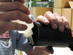
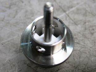
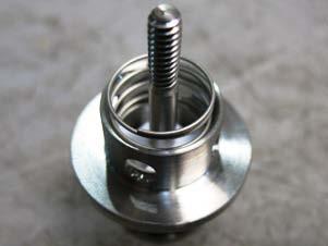
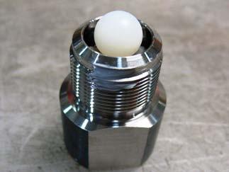
2 soak the Seal (P/N 92509) in a cup of hot water to make it more flexible for assembly STEP 13 fold the Stop Ring (P/N S ) as shown to facilitate installation STEP 14 install the Stop Ring into the groove in the Air Valve Body (P/N ) STEP 15 lubricate the inside of the Air Valve Body with Molykote 55 or equivalent K:\Data\Visual Work Instructions\VWI S-86 (2-15) Booster.xls Page 2 of 31

 O-Ring (P/N 79552-5) around each of two (2) Bolts (P/N")
 Detent Pin (P/N 82871) into each Bolt over the Spring")
 Booster.")
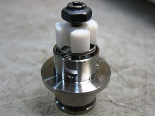
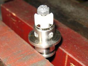
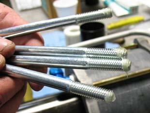
3 STEP 16 lubricate the Shuttle Assembly with Molykote 55 or equivalent STEP 17 install the Shuttle Assembly into the Air Valve Body ensure the end marked "Top" is up STEP 34 install one (1) O-Ring (P/N ) around each of two (2) Bolts (P/N 78238) install one (1) Spring (P/N 88543) into each Bolt install one (1) Detent Pin (P/N 82871) into each Bolt over the Spring coat the tips of the Detent Pins with Molykote 55 or equivalent K:\Data\Visual Work Instructions\VWI S-86 (2-15) Booster.xls Page 3 of 31
 lubricate O-Ring (P/N 91417-256) with Molykote")
 install Retaining Clips (P/N 005-706) and Air")
")
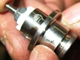
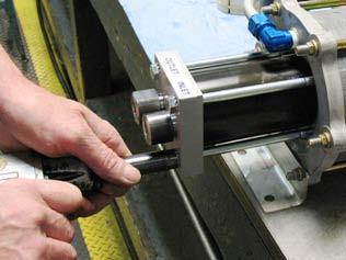
4 STEP 35 thread the Detent assemblies into the Upper Housing assembly use wrench or pneumatic gun to tighten completely (must be able to remove in field using standard tools) lubricate O-Ring (P/N ) with Molykote 55 or equivalent place O-Ring (P/N ) on Air Motor Cover lubricate O-Ring (P/N ) with Molykote 55 or equivalent place O-Ring in Air Motor Cover (P/N ) install Retaining Clips (P/N ) and Air Valve assembly (P/N ) onto Air Motor Cover ensure the lettering on the Air Motor Cover is aligned correctly with the Inlet Port of the Air Valve assembly K:\Data\Visual Work Instructions\VWI S-86 (2-15) Booster.xls Page 4 of 31
 Hex Head Screws (P/N MS90725-3)")

 in a vise install the Cover (P/N")
 Booster.")
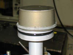
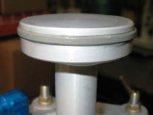
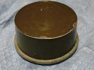
5 place one (1) Lock Washer (P/N MS ) over each of six (6) Hex Head Screws (P/N MS ) thread six (6) Hex Head Screws (P/N MS ) through Retaining Clips into the Air Motor Cover; tighten completely secure the Piston (P/N 88622) in a vise install the Cover (P/N 88623) over the Piston K:\Data\Visual Work Instructions\VWI S-86 (2-15) Booster.xls Page 5 of 31
 install Air Pump Piston")
 and Nut (P/N MS51968-15) onto Piston")

")
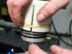
6 install O-Ring (P/N ) into the groove in the Air Pump Piston (P/N ) install Air Pump Piston subassembly onto End Cap subassembly install Washer (P/N AN ) and Nut (P/N MS ) onto Piston install the Seal (P/N 92508) onto the Air Pump Piston over the O-ring the Seal System should fit completely into the groove around the Air Pump Piston K:\Data\Visual Work Instructions\VWI S-86 (2-15) Booster.xls Page 6 of 31
 with the")


 Booster.")
7 thread the Shifting Nut (P/N 78259) onto the end of the Connecting Rod (P/N ) with the longer threads place Lock Washer (P/N MS ) over Connecting Rod screw Connecting Rod into Air Motor Piston and tighten do not over-tighten place a small amount of Loctite 271 onto the threads of the Connecting Rod K:\Data\Visual Work Instructions\VWI S-86 (2-15) Booster.xls Page 7 of 31

 over Connecting Rod install the Air")

")
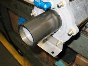
8 STEP 25 install Air Pump Cylinder (P/N 88191) around Air Motor Piston subassembly at a 45 angle ensure the Cylinder lies flat against the End Cap subassembly place Stop Sleeve (P/N ) over Connecting Rod install the Air Motor Cover over the Connecting Rod and onto the Cylinder ensure the Connecting Rod goes through the center of the Guide Sleeve (P/N 92249) in the Air Valve Assembly K:\Data\Visual Work Instructions\VWI S-86 (2-15) Booster.xls Page 8 of 31
 Washer (P/N ) onto each of the six (6) Bolts (P/N 91661) install Mounting")

 Booster.")
9 ensure the air inlet port on the Air Valve Body is aligned with the air transfer port on the End Cap install one (1) Washer (P/N ) onto each of the six (6) Bolts (P/N 91661) install Mounting Bracket (P/N 88187) onto Air Motor Cover with two (2) Bolts the head of the Bolts should be on the same side as the Air Valve assembly and the Mounting Bracket should be opposite the lettering on the Air Motor Cover insert four (4) Bolts with Washers (P/N AN L) and Nuts (P/N MS ) into the remaining bolt holes K:\Data\Visual Work Instructions\VWI S-86 (2-15) Booster.xls Page 9 of 31


 onto Air Valve Assembly secure with")

10 install Self-Locking Nut (P/N 90686) onto the Connecting Rod lubricate Packing O-Ring ( ) with Molykote 55 or equivalent install Packing O-Ring into the groove in the Air Valve Body install Air Valve Cover (P/N ) onto Air Valve Assembly secure with four (4) Hex Head Screws (P/N MS ) K:\Data\Visual Work Instructions\VWI S-86 (2-15) Booster.xls Page 10 of 31


 on each Bolt")

11 lubricate the threads on each Bolt with Petroleum Jelly place the other Mounting Bracket on the End Cap and secure with a Washer (P/N AN L) and Nut (P/N MS ) on each Bolt K:\Data\Visual Work Instructions\VWI S-86 (2-15) Booster.xls Page 11 of 31

 thread one 90 Elbow into the air transfer port of the Air")
 Booster.")
12 secure Bolts with a Washer (P/N AN L) and Nut (P/N MS ) on each Bolt tighten each Nut with a 9/16" wrench torque to ft. lbs. tape and lubricate the square male side of the 90 Elbow (P/N MS D) thread one 90 Elbow into the air transfer port of the Air Valve Body thread one 90 Elbow into the air transfer port of the End Cap K:\Data\Visual Work Instructions\VWI S-86 (2-15) Booster.xls Page 12 of 31


13 K:\Data\Visual Work Instructions\VWI S-86 (2-15) Booster.xls Page 13 of 31


")
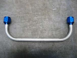
14 install the 3/8" tubing assembly onto the 90 Elbows in the air transfer ports of the Air Valve Body and End Cap install the 5/8" tubing assembly onto the 90 Elbows in the exhaust port of the Air Valve Body and the 90 Elbow in the Cooling Jacket K:\Data\Visual Work Instructions\VWI S-86 (2-15) Booster.xls Page 14 of 31
15 K:\Data\Visual Work Instructions\VWI S-86 (2-15) Booster.xls Page 15 of 31


16 K:\Data\Visual Work Instructions\VWI S-86 (2-15) Booster.xls Page 16 of 31

17 K:\Data\Visual Work Instructions\VWI S-86 (2-15) Booster.xls Page 17 of 31

18 K:\Data\Visual Work Instructions\VWI S-86 (2-15) Booster.xls Page 18 of 31


19 K:\Data\Visual Work Instructions\VWI S-86 (2-15) Booster.xls Page 19 of 31

20 K:\Data\Visual Work Instructions\VWI S-86 (2-15) Booster.xls Page 20 of 31


21 K:\Data\Visual Work Instructions\VWI S-86 (2-15) Booster.xls Page 21 of 31

22 K:\Data\Visual Work Instructions\VWI S-86 (2-15) Booster.xls Page 22 of 31

23 K:\Data\Visual Work Instructions\VWI S-86 (2-15) Booster.xls Page 23 of 31


 Booster.")
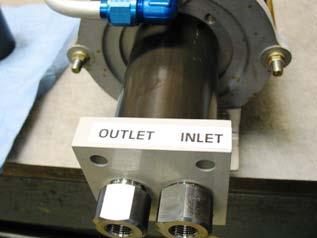
24 STEP 61 visually examine the booster for workmanship refer to the Pressure Rating Table to determine the appropriate Inlet Precharge and Minimum Outlet Pressures STEP 62 i install hose adaptor into the air valve inlet K:\Data\Visual Work Instructions\VWI S-86 (2-15) Booster.xls Page 24 of 31


25 install hose adaptor into the Inlet Check Valve Body install Test Muffler STEP 63 install the Discharge Pressure Gage into the Outlet Check Valve K:\Data\Visual Work Instructions\VWI S-86 (2-15) Booster.xls Page 25 of 31
 to the air valve inlet STEP 69 close")
 Booster.")
26 STEP 67 connect the precharge hose to the Inlet Check Valve port STEP 68 connect the driving air supply (shop air at 100 PSI driving air pressure) to the air valve inlet STEP 69 close the Bleed Valve open the Air Shut Off Valve STEP 70 slowly raise the Precharge to the appropriate pressure K:\Data\Visual Work Instructions\VWI S-86 (2-15) Booster.xls Page 26 of 31

 Booster.")
27 STEP 71 once the Precharge reaches the appropriate minimum pressure, verify that the rated Outlet Pressure has been obtained STEP 72 stall the booster to verify the Inlet Check Valve performance close the Air Shut Off Valve STEP 73 disconnect the driving air supply hose to verify the Outlet Check Valve performance the gage should continue to read the appropriate rated Outlet Pressure STEP 74 for the booster to be acceptable, there should be no indication of external leakage or check valve leakage the booster should operate smoothly without sticking, binding, or hesitation at all pressures K:\Data\Visual Work Instructions\VWI S-86 (2-15) Booster.xls Page 27 of 31
28 STEP 75 open the Bleed Valve STEP 76 open the Precharge Valve STEP 77 disconnect the precharge hose from the Inlet Check Valve port release the pressure in the booster by turning the red handle on the Discharge Pressure Gage K:\Data\Visual Work Instructions\VWI S-86 (2-15) Booster.xls Page 28 of 31
29 K:\Data\Visual Work Instructions\VWI S-86 (2-15) Booster.xls Page 29 of 31


")
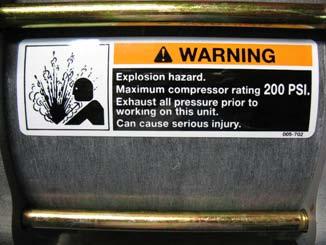
30 STEP 78 unscrew and remove the test muffler remove the Discharge Pressure Gage and all remaining adaptors STEP 79 install thread protector plugs into all of the ports STEP 80 make Nameplate add Nameplate to the front of the booster add sticker to the front of the booster K:\Data\Visual Work Instructions\VWI S-86 (2-15) Booster.xls Page 30 of 31

 Booster.")
31 STEP 81 make appropriate cardboard box ( x x ) write the model number, the part number, the serial number, and the date code onto the box STEP 82 place completed booster in box include an Operation and Maintenance Manual, a Warranty Tracking Form, the Illustrated Parts Breakdown, and the Rear Support in the box DO NOT staple the box closed; it will be "foamed" in shipping to eliminate movement Comments: K:\Data\Visual Work Instructions\VWI S-86 (2-15) Booster.xls Page 31 of 31
Relief Valve Assembly and Testing Procedures
 Template Systems2win.com. Licensed for use only by Curtiss Wright Flow Control - Farris Group (4 locations) Prepared By: M. Dacar Engineering Approval: B. Smith Quality Approval: J. Kabat Revision Date:
INSTALLATION INSTRUCTIONS FOR THE TRUCK MOUNTED VIPER ADDITIVE INJECTION SYSTEM GTP-8776C
 INSTALLATION INSTRUCTIONS FOR THE TRUCK MOUNTED VIPER ADDITIVE INJECTION SYSTEM GTP-8776C This additive injection system was designed to be used with five gallon jug of additive. The system is supplied
H2O-C14 AAA FINE FINISH SERIES PUMP OUTFIT
 PRODUCT INFORMATION H2O-C14 AAA FINE FINISH SERIES PUMP OUTFIT The H2O-C14 AAA pump system is an air assisted airless unit which combines airless and conventional or HVLP air atomization technologies to
Maintenance Information
 45761848 Edition 3 February 2014 Air Die Grinder AC4A, SC4A and XC4A Series Maintenance Information Save These Instructions Product Safety Information WARNING Failure to observe the following warnings,
1.28 ACCESSORY DRIVE. Accessory Drive Assembly Related Parts (Former Design) SERIES 60 SERVICE MANUAL. 1. Locknut 8. Drive Gear
 SERIES 60 SERVICE MANUAL. 1. Locknut 8. Drive Gear") SERIES 60 SERVICE MANUAL 1.28 ACCESSORY DRIVE The accessory drive assembly is mounted to the front of the gear case cover and utilizes a two-groove pulley to drive the alternator. See Figure 1-413, and
SERIES 60 SERVICE MANUAL 1.28 ACCESSORY DRIVE The accessory drive assembly is mounted to the front of the gear case cover and utilizes a two-groove pulley to drive the alternator. See Figure 1-413, and
NUMBER: S.M. REF.: Listed in Table ENGINE: EPA07 Series 60 DATE: October 2012 SUBJECT: REFERENCES TO THE TURBOCHARGER PURGE ROUTINE
 NUMBER: 10 01 12 S.M. REF.: Listed in Table ENGINE: EPA07 Series 60 DATE: October 2012 SUBJECT: REFERENCES TO THE TURBOCHARGER PURGE ROUTINE ADDITIONS, REVISIONS, OR UPDATES Publication Number Platform
B14 AAA FINE FINISH SERIES PUMP OUTFIT
 PRODUCT INFORMATION B14 AAA FINE FINISH SERIES PUMP OUTFIT The B14 AAA pump system is an air assisted airless unit which combines airless and conventional or HVLP air atomization technologies to produce
B14 AAA FINE FINISH SERIES PUMP OUTFIT
 PRODUCT INFORMATION B14 AAA FINE FINISH SERIES PUMP OUTFIT The B14 AAA pump system is an air assisted airless unit which combines airless and conventional or HVLP air atomization technologies to produce
Operation and Maintenance Manual
 Operation and Maintenance Manual MODEL S-216-J-( ) Series AIR-DRIVEN HYDRAULIC PUMP ISSUED NOVEMBER 1994 Revised February 2005 Sprague Products Division of Curtiss-Wright Flow Control Corporation 10195
Maintenance Manual 4½-INCH INTERNAL VALVE F635 SERIES
 Maintenance Manual 4½-INCH INTERNAL VALVE F635 SERIES REVISION 1.0 11/01/2004 LIST OF EFFECTIVE PAGES On a revised page, the portion of text or illustrations affected by the change is indicated by a vertical
RELEASING PRESSURE IN THE HYDRAULIC SYSTEM,
 Testing And Adjusting Introduction NOTE: For Specifications with illustrations, make reference to SPECIFICATIONS for 225 EXCAVATOR HYDRAULIC SYSTEM, Form No. SENR7734. If the Specifications are not the
AIR/HYDRAULIC INJECTION GUN MODEL INSTRUCTIONS
 I. OPERATION & DESCRIPTION The Air / Hydraulic Injection Gun is a high-pressure tool that should be used with caution and according to these instructions. IMPORTANT: The Gun is 0,000 psi rated. Do not
Maintenance Information
 51984144 Edition 6 May 2014 Air Paving Breaker MX60 & MX90 Maintenance Information Save These Instructions Product Safety Information WARNING Failure to observe the following warnings, and to avoid these
Hydraulics. Part B, Section 1. This section covers the following unit configurations. 3700V 3800V 3900V
 Part B, Section 1 Model Voltage Pump Manifold Control This section covers the following unit configurations. 3500V 3700V 3800V 3900V All Piston (F) 4-Port (A) 6-Port (B or C) -Port (S or T) Vista Standard
Installing the Integral Platen Blow Off Valve
 Instruction Sheet Installing the Integral Platen Blow Off Valve WARNING: Allow only qualified personnel to perform the following tasks. Observe and follow the safety instructions in this document and all
3 Inch & 4 Inch Digital Bypass Pressure Control Valves
 SM64505 September 2008 Aerospace Group Conveyance Systems Division Carter Brand Ground Fueling Applicable addition manuals: None Maintenance & Repair Manual 3 Inch & 4 Inch Digital Bypass Pressure Control
WARNING DYNABRADE. Air Powered Abrasive Belt Machine
 For Serial No.9I1001 and Higher Parts Page Reorder No. PD00 50 Effective June, 2000 Supercedes PD96 16 66402 Tool Post Grinder Instruction Manual Air Powered Abrasive Belt Machine! WARNING Always operate,
DP5 Pump. 5:1, Air-operated, Heavy Duty, Oil. General. Operation. Technical Data. Installation R1 09/10
 DP5 Pump 5:1, Air-operated, Heavy Duty, Oil General The DP5 Pump is a compressed air-operated reciprocating piston medium pressure pump. These pumps are suitable for distribution of all types of light
6200 Series. Specifications. Fluid End Power End Models 6211, 6212, 6221, & 6222 Models 6241 & 6242 Part Material Part Material Part Material
 5.2018.12.i 6200 Series Specifications The Flomore 6200 Series Pump line consists of a series of basic pump options all developed from a modular power unit. All units are pneumatically driven positive
DP3 Pump. 3:1, Air-operated, Oil. General. Operation. Technical Data. Installation R0 10/09. 35a 35b 35c
 DP3 Pump 3:1, Air-operated, Oil General The DP3 Pump is a compressed air-operated piston reciprocating medium pressure pump. Suitable for medium flow transfer of high viscosity lubricants and for oil delivery
DP556 Pump. 55:1, Air-operated, Grease. General. Operation. Technical Data. Installation. Mounting with Reinforced Cover (Recommended)
") DP556 Pump 55:1, Air-operated, Grease General The DP556 Pump is a compressed air-operated reciprocating piston pump. This high capacity demand pump is compatible with mineral and synthetic grease and suitable
DP556 Pump 55:1, Air-operated, Grease General The DP556 Pump is a compressed air-operated reciprocating piston pump. This high capacity demand pump is compatible with mineral and synthetic grease and suitable
ANDERSON GREENWOOD SERIES 500 PILOT OPERATED SAFETY RELIEF VALVES INSTALLATION AND MAINTENANCE INSTRUCTIONS
 Before installation these instructions must be fully read and understood TABLE OF CONTENTS 1. General valve description and start-up... 1 2. Main valve maintenance... 1 3. Pilot maintenance... 5 4. Pilot
Baumann Mikroseal Control Valve
 Instruction Manual 81000 Valve Baumann 81000 Mikroseal Control Valve Contents Introduction... 1 Scope of Manual... 1 Safety Precautions... 2 Maintenance... 3 Installation... 3 Air Piping... 4 Flow Direction...
Paint Pumps INST Manual
 OP Series Air Motor Paint Pumps INST Manual OPERATING MANUAL WITH PARTS IDENTIFICATION IPM INC. Manufactured by International Pump Manufacturing, Inc. Covers models: IP22, IP23 and IP24. Manual Number:
SINGLE ACTION FLUID PUMP
 SINGLE ACTION FLUID PUMP MODELS 4490, 4491, 4492 S SERIES A Model 4492 (Stub Pump) Model 4491 (250-275 Gal) Model 4490 (16-55 Gal) Model A52347R-248 (250-275 Gal NOV - 2006 Section -A6 Page -63A Table
CL Series Impeller Shaft Assembly Service Parts List
 Document Number Issue Date 08/91 Rev. Date 10/17/11 CL Series Impeller Shaft Assembly Service Parts List Index: See Pages Pump Model Component Mechanical Seal Packing Heater Jacket Option Previous Seal
Air Driven Gas Boosters
 Features & Benefits Sprague Products pneumatic boosters offer a cost effective way to compress shop air or bottled gas to meet various requirements for higher pressure, lower volume air or gas. Industrial
INSTALLATION/OPERATION/MAINTENANCE INSTRUCTIONS FOR ARCHON MODELS WD2010L, WD2010, WD2010H WASHDOWN STATIONS. ARCHON Industries, Inc.
 ARCHON Industries, Inc. Washdown Stations Models WD2010L, WD2010, WD2010H Installation / Operation / Maintenance Instructions 1 This manual has been prepared as an aid and guide for personnel involved
SM64052 Maintenance & Repair Manual Commercial 2" Unisex Coupling - Valved Model 64052
 Aerospace Group Conveyance Systems Division Carter Brand Ground Fueling Equipment SM64052 July 2004 Applicable additional manuals: SM64051 Commercial 2" Unisex Coupling, Non-Valved Maintenance & Repair
EQUALIZER International Limited 10T(I) Integral Hydraulic Spreading Wedge Repair Instruction Manual
 Integral Hydraulic Spreading Wedge Repair Instruction Manual") EQUALIZER International Limited 10T(I) Integral Hydraulic Spreading Wedge Repair Instruction Manual INDEX THE EQUALIZER 10T(I) Integral Hydraulic Wedge SECTION CONTENTS PAGE NO (S) 03 04 05 06 07 08 09
EQUALIZER International Limited 10T(I) Integral Hydraulic Spreading Wedge Repair Instruction Manual INDEX THE EQUALIZER 10T(I) Integral Hydraulic Wedge SECTION CONTENTS PAGE NO (S) 03 04 05 06 07 08 09
Instructions for Installation, Operation Care and Maintenance
 Model A Dry Pipe Valve Bulletin 353 Rev.K Bulletin 353 Rev.K Instructions for Installation, Operation Care and Maintenance 2 1 2 (65mm) Valve With Model A Trim Listed by Underwriters Laboratories, Inc.
3 Inch & 4 Inch Fuel Operated Bypass Pressure Control Valves. Models & 64513
 SM64503 September 2008 Aerospace Group Conveyance Systems Division Carter Brand Ground Fueling Equipment Applicable addition manuals: None Maintenance & Repair Manual 3 Inch & 4 Inch Fuel Operated Bypass
Anderson Greenwood Series 800 POSRV Installation and Maintenance Instructions
 Before installation these instructions must be fully read and understood Table of contents 1. General valve description and start-up... 1 2. Main valve maintenance... 2 3. Pilot maintenance... 6 4. Pilot
Instructions for Installation, Operation, Care and Maintenance
 Model D Dry Pipe Valve Bulletin 350 Rev. S Bulletin 350 Rev. S Instructions for Installation, Operation, Care and Maintenance 4 (100mm) 6 (150mm) Valve With Model D Trimmings Listed by Underwriters Laboratories,
Property of American Airlines
 Date: September, 00 MALABAR INTERNATIONAL AIRCRAFT MAINTENANCE & SUPPORT EQUIPMENT READ AND SAVE THIS INSTRUCTION MANUAL OWNER'S MANUAL FOR MALABAR MODEL A SINGLE STAGE VARIABLE HEIGHT HYDRO - MECHANICAL
PNEUMATIC SLIDING VALVE
 INSTALLATION, OPERATION, & #: MM-SV001 6-23-09 Rev. A Page 1 of 8 PNEUMATIC SLIDING VALVE PART NUMBERS (Including, but not inclusive) SV704MSTS, SV714MSTS, SV754MSTS, SV764MSTS, SV774MSTS, SV706MSTS, SV716MSTS,
TOYOTA Runner (17 Beadlock ) ALLOY WHEEL Preparation
 ALLOY WHEEL Preparation") Preparation Part Number: PTR45-35010 Kit Contents Item # Quantity Reqd. Description 1 1 Forged Al Wheel 17 x7.5 x 6mm Hardware Bag Contents Item # Quantity Reqd. Description 1 1 per wheel TRD Center Cap
Preparation Part Number: PTR45-35010 Kit Contents Item # Quantity Reqd. Description 1 1 Forged Al Wheel 17 x7.5 x 6mm Hardware Bag Contents Item # Quantity Reqd. Description 1 1 per wheel TRD Center Cap
INSTALLATION, OPERATION, AND MAINTENANCE MANUAL WELKER SAMPLE / INJECTION PUMP
 INSTALLATION, OPERATION, AND MAINTENANCE MANUAL WELKER SAMPLE / INJECTION PUMP MODEL SSO-9MED DRAWING NUMBERS AD243DI AD243DK AD243DK.K1 MANUAL NUMBER IOM-175 REVISION Rev. B, 3/21/2017 TABLE OF CONTENTS
Firehawk Second Stage Regulator Fire Service
 Firehawk Second Stage Regulator Fire Service MAINTENANCE AND REPAIR TAL 1701 (L) Rev. 2 MSA 2017 Prnt. Spec. 10000005389(I) Mat. 10147454 Doc. 10147454 TAL 1701 (L) Rev. 2-10147454 2 NON-CBRN FIREHAWK
Maintenance Information
 80234313 Edition 2 May 2014 Air Grinder, Die Grinder, Sander and Belt Sander Series G1 (Angle) Maintenance Information Save These Instructions Product Safety Information WARNING Failure to observe the
Disassembly Instructions hp. Dynafile II Models: 40352, 40353
 Disassembly Instructions - 0.4 hp. Dynafile II Models: 40352, 40353 Important: Use these instructions along with the tool parts page or manual. Notice: Shut off the air supply and depress throttle lever
Air / Hydraulic Under Axle Jack
 655 Eisenhower Drive Owatonna, MN 55060-0995 USA Phone: (507) 455-7000 Tech. Serv.: (800) 533-6127 Fax: (800) 955-8329 Order Entry: (800) 533-6127 Fax: (800) 283-8665 International Sales: (507) 455-7223
USER MANUAL. LP Unit 5000 PSI. HP Unit 7500 ALL - IN - ONE ALL - IN - ONE ALL - IN - ONE. 4" Drive Handles. LP Units Available in 12" Insertion Length
 LP Unit 5000 PSI Flow Innovations MADE IN USA USER HP Unit 7500 PSI MANUAL Flow Innovations MADE IN USA ATOMIZER ATOMIZER COUPON HOLDER 4" Drive Handles COUPON HOLDER INJECTION QUILL INJECTION QUILL LP
Vickers. Overhaul Manual. Transmissions. Adjustable Speed Hydraulic Drives. TR3, PTR3 and MTR3 Series -20 Design
 Overhaul Manual Vickers Transmissions Adjustable Speed Hydraulic Drives TR3, PTR3 and MTR3 Series -20 Design Revised 9/1/87 I-1820-S 2 Eaton Hydraulics, Incorporated 2000 All Rights Reserved Table of Contents
Maintenance Manual 6-INCH INTERNAL VALVE F620 SERIES
 Maintenance Manual 6-INCH INTERNAL VALVE F620 SERIES REVISION 1.1 03/15/2002 LIST OF EFFECTIVE PAGES On a revised page, the portion of text or illustrations affected by the change is indicated by a vertical
HOW THE SPRAGUE PRODUCTS BOOSTERS WORK
 SUPERCHARGE SHOP AIR OR BOTTLED GAS WITH SPRAGUE PRODUCTS GAS BOOSTER Sprague Products pneumatic boosters offer a cost effective way to compress shop air or bottled gas to meet various requirements for
Models & Inch & 4 Inch Digital Inline Pressure Control Valves SM64504
 SM64504 September 2008 Aerospace Group Conveyance Systems Division Carter Brand Ground Fueling Equipment Applicable addition manuals: None Maintenance & Repair Manual 3 Inch & 4 Inch Digital Inline Pressure
INSTALLATION MANUAL. MB-250, MB-280 and MB-320 Motor Brake INSTALLATION. Force Control Industries, Inc. DESCRIPTION OPERATION
 MB-250, MB-280 and MB-320 Motor Brake INSTALLATION MANUAL 512-250-001-00 DESCRIPTION Posistop Motor Brakes are multiple surface, spring activated, pneumatic release braking devices that effectively dissipate
Model 8317 Combination Shower Eye/Face Wash
 INSTALLATION, OPERATION & MAINTENANCE INSTRUCTIONS 1455 Kleppe Lane Sparks, NV 89431-6467 (775) 359-4712 Fax (775) 359-7424 E-mail: haws@hawsco.com website: www.hawsco.com Model 8317 Combination Shower
Servicing the Tool. Service Kit SERVICE KIT. For all servicing we recommend the use of the service kit (part number (S)).
).") Servicing the Tool Service Kit For all servicing we recommend the use of the service kit (part number 07900-04750(S)). SERVICE KIT ITEM PART Nº DESCRIPTION Nº OFF ITEM PART Nº DESCRIPTION Nº OFF 07900-00002
Servicing the Tool Service Kit For all servicing we recommend the use of the service kit (part number 07900-04750(S)). SERVICE KIT ITEM PART Nº DESCRIPTION Nº OFF ITEM PART Nº DESCRIPTION Nº OFF 07900-00002
Maintenance Manual Reduced Pressure Assembly Models 860 & 880V 2 1 /2" 10"
 IOM-F-860_880V INSTALLATION, OPERATION, MAINTENANCE Maintenance Manual Reduced Pressure Assembly Models 860 & 880V 2 1 /2" 10" 860 880V Standard Configuration 880V Vertical Configuration INDEX Vandalism..............................................
SW14.5TI INTEGRAL HYDRAULIC FLANGE SPREADING WEDGE. Repair Manual INNOVATION IN ITS MOST FUNCTIONAL FORM
 SW14.5TI INTEGRAL HYDRAULIC FLANGE SPREADING WEDGE Repair Manual info@equalizerinternational.com www.equalizerinternational.com INNOVATION IN ITS MOST FUNCTIONAL FORM INDEX SECTION CONTENTS PAGE NO. 1
Implement and Steering/Hydraulic System Testing and Adjusting
 Page 1 of 64 Testing And Adjusting Introduction Reference: This supplement contains the Specifications, Systems Operation, and Testing And Adjusting for the components and systems that are different than
LOW PRESSURE BALANCED VALVE DIAPHRAGM BALANCED
 DIAPHRAGM BALANCED All Rights Reserved. All contents of this publication including illustrations are believed to be reliable. And while efforts have been made to ensure their accuracy, they are not to
Disassembly Instructions hp. Mini-Dynafile II
 Disassembly Instructions - 0.4 hp. Mini-Dynafile II Important: Use these instructions along with the tool parts page or manual. Notice: Shut off the air supply and depress throttle lever to deplete the
INSTALLATION, OPERATION, & MAINTENANCE MANUAL
 Environmental Performance for Industry! F70VP SERIES VACUUM RELIEF VALVE INSTALLATION, OPERATION, & Revision: A Date of Issue: Oct. 31, 2003 Approved by: Design Engineer Service Manager Engineering Manager
Maintenance Information
 04581245 Edition 2 May 2014 Air Grinder, Die Grinder and Sander Series G2 (Angle) Maintenance Information Save These Instructions Product Safety Information WARNING Failure to observe the following warnings,
Property of American Airlines
 Date: November 22, 1999 MALABAR INTERNATIONAL AIRCRAFT MAINTENANCE & SUPPORT EQUIPMENT READ AND SAVE THIS INSTRUCTION MANUAL OWNER'S MANUAL FOR MALABAR MODEL 60P10 TWO STAGE HYDRAULIC AVIATION FLOATING
Air Assist Bottle Jack Max. Capacity: 12 Tons (4313C) & 20 Tons (4321C) Operating Range: psi
 & 20 Tons (4321C) Operating Range: psi") R SPX Division 655 Eisenhower Drive Owatonna MN 55060 Phone: (507) 455-7000 Tech. Serv.: (800) 533-6127 Fax: (800) 955-8329 Order Entry: (800) 533-6127 Fax: (800) 283-8665 International Sales: (507) 455-7223
R SPX Division 655 Eisenhower Drive Owatonna MN 55060 Phone: (507) 455-7000 Tech. Serv.: (800) 533-6127 Fax: (800) 955-8329 Order Entry: (800) 533-6127 Fax: (800) 283-8665 International Sales: (507) 455-7223
Section 8. Parts A Issued 7/00. Manual V -MA -01 (formerly 7-505/6V -MA -01) E 2000 Nordson Corporation All rights reserved
 E 2000 Nordson Corporation All rights reserved") Section 8 E 000 Nordson Corporation 00 497A Manual 47-506V -MA -0 (formerly 7-505/6V -MA -0) 8-0 Manual 47-506V -MA -0 (formerly 7-505/6V -MA -0) 00 497A E 000 Nordson Corporation 8- Section 8. Introduction
Section 8 E 000 Nordson Corporation 00 497A Manual 47-506V -MA -0 (formerly 7-505/6V -MA -0) 8-0 Manual 47-506V -MA -0 (formerly 7-505/6V -MA -0) 00 497A E 000 Nordson Corporation 8- Section 8. Introduction
Maintenance Manual. 3-Inch Internal Valve. F660 Series
 3-Inch Internal Valve F660 Series LIST OF EFFECTIVE PAGES On a revised page, the portion of text or illustrations affected by the change is indicated by a vertical line in the outer margin of the page.
Operating and Maintenance Manual Gas & Diesel Engine Powered Self-Priming Trash Pumps Series
 Operating and Maintenance Manual Gas & Diesel Engine Powered Self-Priming Trash Pumps 3200 Series Operating Manual Contents: Model Number/Serial Number/Safety Information Pg. 1 Safety Information (Con
Maintenance Manual 3-INCH INTERNAL VALVE F660 SERIES
 Maintenance Manual 3-INCH INTERNAL VALVE F660 SERIES REVISION 1.1 03/15/2002 LIST OF EFFECTIVE PAGES On a revised page, the portion of text or illustrations affected by the change is indicated by a vertical
Telephone:(925) Fax:(925) Lawrence Drive, Livermore, CA
 Fax:(925) Lawrence Drive, Livermore, CA") Telephone:(95)5-9500 Fax:(95)5-950 5 Lawrence Drive, Livermore, CA 955 www.fabcoautomotive.com Table of Contents This manual covers single and dual rear output versions of the TC- two-speed transfer case
Telephone:(95)5-9500 Fax:(95)5-950 5 Lawrence Drive, Livermore, CA 955 www.fabcoautomotive.com Table of Contents This manual covers single and dual rear output versions of the TC- two-speed transfer case
PowrTwin 6900GHD Insert Sheet
 For professional use only PowrTwin 00GHD Insert Sheet Parts Lists and Service Instructions Main Assembly Model Numbers: Gas Bare -0 Gas Complete -0 Gas/Electric Complete -0 0V Electric International -0
Air Assist Bottle Jack Max. Capacity: 12 Tons (4313C) & 20 Tons (4321C) Operating Range: psi
 & 20 Tons (4321C) Operating Range: psi") Form No. 545742 Parts List and Operating Instructions for: 4313C 4321C Air Assist Bottle Jack Max. Capacity: 12 Tons (4313C) & 20 Tons (4321C) Operating Range: 40 150 psi 45 44 43 42 41 40 39 22 1 37 28
Form No. 545742 Parts List and Operating Instructions for: 4313C 4321C Air Assist Bottle Jack Max. Capacity: 12 Tons (4313C) & 20 Tons (4321C) Operating Range: 40 150 psi 45 44 43 42 41 40 39 22 1 37 28
SERIES 270A HIGH SIDE FLOAT VALVES BULLETIN 270A-SB11-02 SERVICE BULLETIN
 VALVES VESSELS SYSTEMS CONTROLS SERIES 270A HIGH SIDE FLOAT VALVES BULLETIN 270A-SB11-02 SERVICE BULLETIN System drawings shown in this bulletin are for illustration purposes only. Refrigeration systems
ASSEMBLY. Transmission Automatic Transmission 5R44E and 5R55E. Special Tool(s)
") 307-01-1 Automatic Transmission 5R44E and 5R55E 307-01-1 ASSEMBLY Transmission Special Tool(s) Holding Fixture, Transmission 307-262 (T93T-77002-AH) Special Tool(s) Installer, Transmission Extension Housing
307-01-1 Automatic Transmission 5R44E and 5R55E 307-01-1 ASSEMBLY Transmission Special Tool(s) Holding Fixture, Transmission 307-262 (T93T-77002-AH) Special Tool(s) Installer, Transmission Extension Housing
Baumann Sanitary Angle Control Valve
 Baumann 83000 Sanitary Angle Control Valve Contents Introduction... 1 Scope of Manual... 1 Safety Precautions... 2 Educational Services... 2 Maintenance... 3 Installation... 3 Air Piping... 4 Flow Direction...
I N S T R U C T I O N M A N U A L
 I N S T R U C T I O N M A N U A L M E T E R I N G P U M P S LINC84T-17, 18 & 20 Series Chemical Metering Pump Pneumatic Plunger T A B L E O F C O N T E N T S Contents - 84T-17, -18 & -20 Pump Manual...
2. Disconnect negative battery cable to avoid possible fuel discharge if an accidental attempt is made to start the engines.
 PART #25001 LT1 Adjustable Fuel Pressure Regulator, 1994-1997 PACKING LIST Before installation, use this check list to make sure all necessary parts have been included. ITEM QTY CHECK PART NUMBER DESCRIPTION
Maintenance Information
 80234313 Edition 1 June 2006 Air Grinder, Die Grinder, Sander and Belt Sander Series G1 (Angle) Maintenance Information Save These Instructions WARNING Always wear eye protection when operating or performing
 Page 1 of 22 SECTION 307-01: Automatic Transaxle/Transmission 4R70E/4R75E ASSEMBLY Procedure revision date: 05/29/2009 Transmission Printable View (1554 KB) Special Tool(s) Air Test Plate, Transmission
Horton DriveMaster Fan Clutch 20.06
 Horton DriveMaster Fan Clutch 0.06 Fan Clutch Major Rebuild 4 4 5 06/05/00 f0057. Spring Housing/Piston ssembly. Cage Nut. Friction Lining 4. Torx-Head Screws Fig. 4, Friction Lining Removal and Installation
JARVIS. Models USSS -1, USSS -2 and USSS -2A Pneumatic Stunners
 \ Models USSS -1, USSS -2 and USSS -2A Pneumatic Stunners Rear Handle for Knocker Box USSS--2A Side Handle for Knocker Box USSS--1 U.S. Patent No. 6,135,871 Patents Pending Worldwide Rear Handle for V
PISTON ACCUMULATOR INSTALLATION, OPERATION & CARE
 PISTON ACCUMULATOR INSTALLATION, OPERATION & CARE www.accumulators.com The user is the sole responsible party to ensure proper selection, installation, operation and maintenance of these products and to
Warning and Safety Precautions
 EXPRESS WARRANTY AND DISCLAIMER OF IMPLIED WARRANTIES Lily Corporation unconditionally guarantees its products to be free of defects in material or workmanship and further warrants that, for a period of
Tech. Services: (800) Fax: (800) Order Entry: (800) Fax: (800) MODEL F AIR HYDRAULIC PUMP
 Fax: (800) Order Entry: (800) Fax: (800) MODEL F AIR HYDRAULIC PUMP") Form No. 08 SPX Corporation 88 th Street Rockford, IL 09-99 USA Internet Address: http://www.hytec.com Tech. Services: (800) 477-8 Fax: (800) 7-8 Order Entry: (800) 4-48 Fax: (800) 88-70 Parts List for:
Form No. 08 SPX Corporation 88 th Street Rockford, IL 09-99 USA Internet Address: http://www.hytec.com Tech. Services: (800) 477-8 Fax: (800) 7-8 Order Entry: (800) 4-48 Fax: (800) 88-70 Parts List for:
Air / Hydraulic Pump
 Form No. 538016 Parts List & Operating Instructions for: 2510A Original Instructions Air / Hydraulic Pump Maximum Capacity: 690 bar (10,000 psi) Description: The 2510A air/hydraulic pump is designed to
Wheel Angle Sensor Kit Installation
 Wheel Angle Sensor Kit Installation Item Component Part Number Qty 1. WAS Bracket Kit 200-0247-02 1 2. WAS Assembly Kit 200-0468-01 1 3. Instruction Guide 602-0401-01 1 602-0401-01-A Overview Always shut
CROSBY SERIES BP OMNI-TRIM PRESSURE RELIEF VALVES INSTALLATION, MAINTENANCE AND ADJUSTMENT INSTRUCTIONS
 Before installation these instructions must be read fully and understood cause misalignment of the valve parts. It is recommended that the valves be left in their original shipping containers and that
Inverted High Pressure Fluid Filters
 Instruction Sheet P/N 33290-03 Description See Figure. Nordson high-pressure fluid filters prevent nozzle-plugging by filtering contaminants out of coating materials. These stainless steel, wall-mounted
INSTALLATION INSTRUCTIONS
 INSTALLATION INSTRUCTIONS BIG ROTOR / CALIPER RELOCATION REAR KIT SUM-BK1423 1999-2009 GM 1/2 Ton Trucks & SUVs Thank you for choosing SUMMIT RACING for your braking needs. Pleases take the time to read
Operation and Maintenance Manual
 BM / BMA Hydrometers ½ Operation and Maintenance Manual i This manual is intended for use by the users of this equipment. The information contained herein is the property of the Arad Ltd. Dalia and may
FlexJet - Flex Cable Replacement
 P/N: 109515R0 14140 NE 200th St. Woodinville, WA. 98072 PH: (425) 398-8282 FX: (425) 398-8383 FlexJet - Flex Cable Replacement Notices: Warning! Ensure that all AC power cables are removed from the printer
Anderson Greenwood Series 400 Piston Pilot POPRV Installation and Maintenance Instructions
 Before installation these instructions must be fully read and understood As capacity relief of the system is satisfied, system pressure will begin to decrease. When it does, the pilot will actuate and
Bottom Loading & Recirculation Adapters
 SM60373 January 2002 Aerospace Group Conveyance Systems Division Carter Brand Ground Fuelin Equipment Applicable additional manuals: None Maintenance Manual Bottom Loading & Recirculation Adapters Models
SERVICE PARTS LIST SPECIFY CATALOG NO. AND SERIAL NO. WHEN ORDERING PARTS 1" D-HANDLE ROTARY HAMMER SERIAL NUMBER G43A See page 6.
 00 0 CATALOG NO. EXAMPLE: Component Parts (Small #) Are Included When Ordering The Assembly (Large #). = Component of the 14-4-525 522-21 Maintenance Service Kit SEE PAGE TWO FOR THE PROCEDURE ON CHECKING
270A SERIES HIGH-SIDE FLOAT VALVES BULLETIN 270A-SB13-01 SERVICE BULLETIN
 VALVES VESSELS SYSTEMS CONTROLS 270A SERIES HIGH-SIDE FLOAT VALVES BULLETIN 270A-SB13-01 SERVICE BULLETIN System drawings shown in this bulletin are for illustration purposes only. Refrigeration systems
28-A DOUBLE CHECK VALVE PORTION, Pc. No
 28-A DOUBLE CHECK VALVE PORTION, Pc. No. 650143 NOVEMBER, 1989 Supersedes issue dated January, 1989 NOTE: The following description and operation is based on this device and its components being new or
18SP631 MBE 4000 Oil Gallery Threaded Plug Installation
 18SP631 MBE 4000 Oil Gallery Threaded Plug Installation KIT DESCRIPTION A new service kit (P/N: 23536501) is now available to install two threaded plugs in place of cup plugs in the rear oil gallery on
REFILL STATION REBUILD KIT P/N 14270NOS
 REFILL STATION REBUILD KIT P/N 14270NOS INSTRUCTION SHEET P/N 199R10338 1.0 DISASSEMBLY This procedure describes the removal of the air module from the fluid module and complete disassembly of the pump.
REMOVAL & INSTALLATION
 REMOVAL & INSTALLATION CAUTION: This application is an interference engine. Do not rotate camshaft or crankshaft when timing belt is removed, or engine damage may occur. TIMING BELT Removal 1. Raise and
GH-BETTIS SERVICE INSTRUCTIONS DISASSEMBLY & REASSEMBLY FOR MODELS HD521-M4, HD721-M4 AND HD731-M4 DOUBLE ACTING SERIES PNEUMATIC ACTUATORS
 GH-BETTIS SERVICE INSTRUCTIONS DISASSEMBLY & REASSEMBLY FOR MODELS HD521-M4, HD721-M4 AND HD731-M4 DOUBLE ACTING SERIES PNEUMATIC ACTUATORS WITH HYDRAULIC CONTROL PACKAGE PART NUMBER: SE-023 REVISION:
Material required for drilled well application (indoor use only)
") SAFETY INSTRUCTIONS: This fine pump that you have just purchased is designed from the latest in material and workmanship. Before installation and operation, we recommend the following procedures: A B C
SAFETY INSTRUCTIONS: This fine pump that you have just purchased is designed from the latest in material and workmanship. Before installation and operation, we recommend the following procedures: A B C
Baumann Series Flexsleev Control Valve Instructions
 Instruction Baumann 86000 Series Instructions Baumann 86000 Series Flexsleev Control Valve Instructions Contents Introduction...1 Scope...1 Safety Precautions...1 Maintenance...2 Installation...3 Air Piping...3
Atlas PV-9WP Addendum
 Atlas PV-9WP Addendum 9,000 lb. Capacity Two-Post Overhead Lift The Atlas PV-9WP above ground hoist is 6 inches wider than the Atlas PV-9P, giving it an overall width of 141 (11 9 ) and a drive thru width
OPERATING INSTRUCTIONS & SERVICE MANUAL BLUE MAX II HYDROSTATIC TEST PUMP
 PAGE 1 OF 10 OPERATING INSTRUCTIONS & SERVICE MANUAL BLUE MAX II HYDROSTATIC TEST PUMP EFFICIENT, EASY OPERATION Air operated pump Wide range of pressures and volumes Easy to operate controls Output pressure
AUTOMATIC TRANSAXLE AUTOMATIC TRANSAXLE SYSTEM... COMPONENT PARTS...
 SYSTEM....... COMPONENT PARTS.................... OIL PUMP.............................. DIRECT CLUTCH........................ FORWARD CLUTCH..................... SECOND BRAKE........................ UNDERDRIVE
Hydraulics. Part B, Section 1. This section covers the following unit configurations. 3400V 3500V 3700V
 Part B, Section 1 This section covers the following unit configurations. Model Voltage Pump Manifold Control 3100V 3400V 3500V 3700V All Piston (E) 4-Port (A) 6-Port (B or C) 2-Port (S or T) Vista Standard