UTS SERIES. Waterproof Plastic Connectors. IP68 and IP69K
|
|
|
- Belinda Mitchell
- 5 years ago
- Views:
Transcription

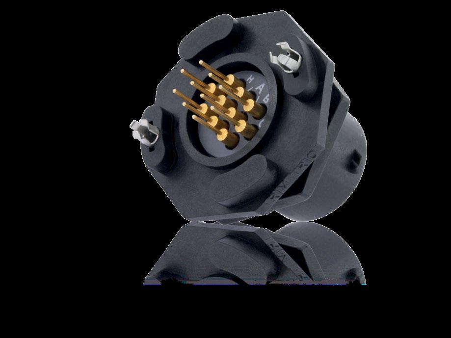
1 UTS SERIES Waterproof Plastic Connectors IP68 and IP69K
2


3 UTS Series Overview Typical Applications Features & Benefits Range Overview Layouts General Technical Characteristics Connector Overmolded Cable Assembly contacts ground contacts contacts ground contacts contacts contacts contacts ground contacts contacts contacts contacts contacts contacts contacts contacts contacts contacts contacts LC (Fiber Optic) MPO (Fiber Optic) Contents Contacts Description Contact Plating Selector Guide Contact Selector Guide Packaging Crimp Contacts #16 Coaxial Contacts PCB Contacts Fiber Optic Contacts Technical Information Tooling Stripping & Crimping Instructions Handle & Interchangeable Heads Insertion & Extraction Tools Overmolded Cable Assembly Dimensions Assembly Instructions Mated Connector Lengths Mating Procedure Rated Current & Working Voltage UV Resistance UL94 + UL IEC & IP Codes Explained IEC Explained What is NEMA Rating? Ethernet for the Layman Appendices #16 Coaxial Contacts/Cabling Notices Glossary of Terms Discrimination/Keying Methods Part Number Index Appendices Technical Information Contacts Connector Overview 3
4 UTS SERIES 2015 SOURIAU - SOURIAU is a registered trademark
5 UTS Series Overview Typical Applications Features & Benefits Range Overview Layouts General Technical Characteristics


6 UTS Series Overview Typical Applications Energy - Power Vibe Images / Fotolia Off-Road - Mining - Railway Sergey Milovidov / Fotolia Building Automation & Control Volodymyr Kyrylyuk / Fotolia Instrumentation - Measurement krungchingpixs / Fotolia Telecom - Data infrastructure Olivier Tuffé / Fotolia cachoudesign / Fotolia Stage - Light 6
7 UTS Series Overview Features & Benefits WATER PROOF UV RESISTANT Dynamic Mated & Unmated Ideal for outdoor and indoor dynamic applications requiring continuous underwater immersion, routine pressure washing and dust protection. No Degradation Over Time No mechanical deterioration or important color variation after 5 years of exposure in natural environment (equivalent exposure to sun and moisture as per ISO4892) and F1 rated per UL 746C. Overview UL/IEC COMPLIANT Qualified & Certified In accordance with: - UL Certificate ECBT2, File number: E CSA C22.2 n Certificate ECBT8, File number: E quick mating 1/3 Bayonet Coupling With only 1/3 twist of the bayonet coupling system, connectors are mated with audible "click" and tactile feel to confirm proper mating. This mating feature eliminates connection uncertainty and reduces time and labor during installation. Cost savings Mixed Power & Signal Layouts Power supply and signal transmission can be combined in a unique interconnect solution to reduce system complexity and minimize component and installation costs. 7


 Choice")


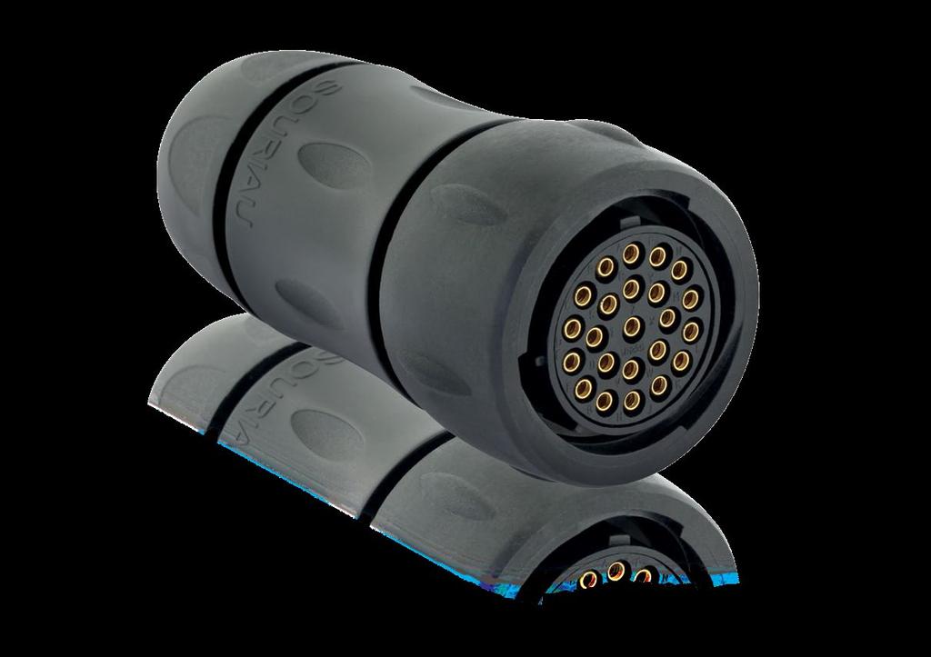
8 UTS Series Overview Range UTS Series UTS Standard Cable Sealed Single Wire Sealed Sealed mated: dynamic UV resistant UL/IEC compliant Corrosion-proof Plastic housing UTS Backshells Contacts Supplied Separately Cable Sealing Double Sealing (Wires + Cable) Choice of Crimp Contacts Machined Stamped and Formed Coaxial PCB Contacts Fiber Optic Contacts Loaded Screw Termination Plug Single Wire Sealed Grommet Contacts Loaded Handsolder Flexible conduit adaptors UTS Sealed Unmated Contact us for more information Overmolded Cable Assembly Sealed Unmated: dynamic MIL-C compatible UV resistant UL/IEC compliant Corrosion-proof Plastic housing 8

 In-line Choice of Crimp")


9 UTS Series Overview Overview UTS Standard Receptacle Contacts Supplied Separately Square Flange Choice of Crimp Contacts Machined Stamped and Formed Coaxial PCB Contacts UTS Backshells Cable Sealing Overview Threaded Receptacle Fiber Optic Contacts Supplied Separately Double Sealing (Wires + Cable) In-line Choice of Crimp Contacts Machined Stamped and Formed Coaxial PCB Contacts Fiber Optic Grommet Single Wire Sealed Jam Nut Contacts Loaded Screw Termination PCB Flexible conduit adaptors UTS Sealed Unmated Receptacle Contact us for more information UTS PCB Contacts Jam Nut Contacts Loaded Handsolder PCB Stand-offs to allow cleaning after soldering Metal hold down clips - to lock the connector easily on the PCB and to release stress on solder joints - suitable for soldering in a metallic hole Square Flange Low profile housing to limit space between panel and PCB Pre-assembled PCB contacts - machined or stamped versions available - different solder tails lengths possible - different plating options 9
10 UTS Series Overview Layouts Shell Size (Electrical parameter according to UL1977) Contact #16 (Ø 1.6mm) Contact #20 (Ø 1.0mm) 8E2/8D2(1) 8E3/8D3(1) Page 20 Page 36 8E3A/8D3A(1) 8E98/8D98(1) Page 40 Page 40 8E33/8D33(1) 8E4*/8D4*(1) Page 44 Page 60 7A 250V 3 contacts 7A 250V 3 contacts A 500V 4 contacts 6A 250V 6 contacts Page 28 Page 68 Page 84 12E2/12D2 13A 650V 2 contacts Page W2 10E98/10D98 10E7(1)/10D7 Page 88 Page 96 12E3/12D3 13A 600V 3 contacts 103W3 20A 500V 4 contacts 10A 500V 6 contacts 2xØ2.4 (#12) 2xØ1.0 (#20) 3xØ1.6 (#16) 3xØ1.0 (#20) Page 64 Page 80 6A 250V 7 contacts 1210* 12E10*/12D10* 5A 250V 10 contacts Page 48 Page E4/12D4 (4) 128(1) (3) 10A 500V 3+ground 10A 500V 8 contacts Page 52 Page 100 1: M12, M16 and M20 threaded receptacle available 10 7A 250V 4 contacts 10A 500V 2+ground 6A 250V 6 contacts 12 7A 250V 3 contacts 106* 10E6*(1)/10D6* 104*(3) Hybrid & others 7A 250V 3 contacts 7A 250V 2 contacts 8 Contact #8 (Ø 3.6mm) 2: NPT available 12E8/12D8 12E14/12D14 Page 104 Page A 250V 8 contacts 4.5A 250V 14 contacts 3: Discrete wire grommet option 4: Screw termination contacts * Ethernet compatible: see pages 195 & 196
11 UTS Series Overview Shell Size Contacts #16: from AWG 30 to to 2.5 mm² Contact #16 (Ø 1.6mm) 14E5/14D (3) (4) 14E7/14D7 12A 600V 5 contacts 10A 500V 6+ground Page 72 Page (3) 1492(3) 10A 500V 12 contacts 10A 600V 12 contacts Contacts #12: from AWG 22 to to 4 mm² Contacts #8: from AWG 16 to to 10 mm² Contact #20 (Ø 1.0mm) Contact #8 (Ø 3.6mm) 14E18/14D18 Hybrid & others G1(2) 4A 250V 18 contacts 44A 600V 2+ground Page 136 Page 32 25A 250V 8 contacts 4xØ1.6 (#16)+4xØ2.4 (#12) Overview Contacts #20: from AWG 26 to to 0.93 mm² Page E12/14D12 4.5A 250V 12 contacts E19/14D19 4xØ1.6 (#16)+8xØ1.0 (#20) 5A 250V 19 contacts Page 120 Page E15/14D15 Page A 600V 15 contacts Page 140 1xØ1.6 (#16)+14xØ1.0 (#20) Page A 500V 23 contacts E32 5A 250V 32 contacts 183G1(2) 18X2M3(2) 44A 600V 3+ground 44A 600V 5 contacts 3xØ1.6 (#16) + 2xØ3.6 (#8) Page 144 Page 148 Page Page 763 LC 18 Page 156 MPO Page 160 XXXXXX blue highlighted items: UTS Sealed in Unmated Condition 11

 see page 188 - UL94 HB (UTS Sealed Unmated version only) see page 188 - I2F3 according to NFF 16101 & NFF 16102 Salt spray: 500")
 and F1 rated per UL 746C Sealing: - UTS Standard: IP68/IP69K dynamic (mated) - UTS Sealed Unmated version: IP68/IP69K dynamic (unmated) - UTS Single Wire Sealed:")

: Sinusoidal vibrations per IEC 60512-4 - from 10 to 2000 Hz Thermal shock: 5 cycles 30")
12 UTS Series Overview General Technical Characteristics Materials Body connector + Backshell: Thermoplastic Insert: - UTS Standard, UTS Single Wire Sealed, UTS Screw Termination Contacts: Thermoplastic - UTS Sealed Unmated Handsolder & UTS Sealed Unmated with PC Tails Contacts: Elastomer Nut: Metal Contacts: See page 161 Halogen free RoHS compliant & conforms to the Chinese standard SJ/T (Chinese RoHS equivalent) Environmental Operating temperature: from -40 C to +105 C 40/100/21 per NFF Flammability rating: - UL94 V-0 (all UTS except the Sealed Unmated version) see page UL94 HB (UTS Sealed Unmated version only) see page I2F3 according to NFF & NFF Salt spray: 500 hours per EIA-026A UV resistant: No mechanical degradation or important color variation after 5 years of exposure in natural environment (equivalent exposure to sun and moisture as per ISO 4892) and F1 rated per UL 746C Sealing: - UTS Standard: IP68/IP69K dynamic (mated) - UTS Sealed Unmated version: IP68/IP69K dynamic (unmated) - UTS Single Wire Sealed: IP67/69K (up to IP68 with double sealing backshell) - UTS Screw Termination Contacts: IP68/IP69K dynamic (mated) Note: IP68=10 m underwater during 1 week Fluid resistance: - Gas and Oil - Mineral Oil - Acid Bath - Basic Bath Electrical In accordance with: - UL 1977: Certificate ECBT2 File number: E CSA C22.2 n 182.3: Certificate ECBT8 File number: E Also see pages 10 & 11 Optical Please consult us for more information about UTSLC and UTSMPO Mechanical Durability: 250 matings & unmatings per MIL-C Vibration resistance (all UTS versions except UTS Screw Termination contacts): Sinusoidal vibrations per IEC from 10 to 2000 Hz Thermal shock: 5 cycles 30 min. from -40 C to 105 C per MIL-STD-1344 method
13 UTS Series Overview Notes Overview 13
14 UTS SERIES 2015 SOURIAU - SOURIAU is a registered trademark
15 UTS Series Connector Overmolded Cable Assembly contacts 8E2/8D2: 7A 250V E2/12D2: 13A 650V contacts + ground 103: 10A 500V G1: 44A 600V contacts 8E3/8D3: 7A 250V E3A/8D3A - 8E98/8D98: 7A 250V E33/8D33: 7A 250V E3/12D3: 13A 600V contacts + ground E4/12D4: 10A 500V G1: 44A 600V contacts 8E4/8D4*: 7A 250V W2: 20A 500V *: 10A 500V contacts 14E5/14D5: 12A 600V X2M3: 44A 600V contacts 103W3: 10A 500V * - 10E6*/10D6*: 6A 250V E98/10D98: 6A 250V contacts + ground E7/14D7: 10A 500V contacts 10E7/10D7: 6A 250V contacts 128: 10A 500V E8/12D8: 4.5A 250V : 25A 250V contacts 1210* - 12E10*/12D10*: 5A 250V contacts 1412: 10A 500V E12/14D12: 4.5A 250V : 10A 600V contacts 12E14/12D14: 4.5A 250V contacts 14E15/14D15: 12A 600V contacts 14E18/14D18: 4A 250V contacts E19/14D19: 5A 250V contacts 1823: 10A 500V contacts E32: 5A 250V LC MPO Electrical parameters according to UL * Ethernet compatible see pages 195 &

16 Overmolded Cable Assembly SOURIAU has provided connectors for various applications for more than 90 years and has been used in the most extreme environments. Conscious about the difficulty in finding a quick and reliable harness manufacturer, we began our own in-house cable assembly production. It allows customers to reduce the number of suppliers and to take advantage of the best in class quality of the SOURIAU group. Overmolding is a process that further enhances the sealing properties and helps to minimize stress on the cable termination to the connector. In addition, the wires are encapsulated inside the molding which creates a barrier preventing liquid/moisture from entering the equipment through the connector or cable jacket if breached. How to choose the outer jacket material Please consult us Cleaner, chlorine TPE Static installation SILICON Static installation Chemical aggression Wet Immersed OUTDOOR (black outer jacket) PUR Static or dynamic installation INDOOR FEP Static installation PTFE Static installation UV resistance PVC Static or dynamic installation -40 C +80 C Ambient temperature 16


17 Overmolding Description Thermoplastic or elastomer insert Compound O-ring Overmolding adapter PVC or PUR overmolding Connector Connector with cable gland backshell If cable jacket is breached... GOOD...water ingress unhampered, leading to damage. Overmolded connector If cable jacket is breached... BEST...prevents water ingress via capillary action. 17

 Applications Industrial Controls Electronics Controlled")


18 UTS Waterproof Plastic Overmold Description Cable PVC Jacket (Black) 16 AWG conductors Multi-conductor 4, 8 or V Unshielded Flammability rating UL 1685 (UL1581 Sec.1160) Applications Industrial Controls Electronics Controlled Environment Equipment LED Lighting Overmolding Specifications PLATING SALT SPRAY TEMPERATURE* WATERPROOF* MECHANICAL No plating 500 H -30 C up to +50 C IP68/IP69K dynamic (mated) 250 matings/unmatings * With appropriate cable and overmolding Example of Customized Cable Assemblies Overmolding on Curly Cable Overmolding with Double Ends Harness for PCB Connection To define your customized cable assembly needs, please contact our Technical Service Team for support. 18
19 Cable Information Range of temperature: -30 C +50 C Rated voltage: U0/U: 300/500V Wire section : Harmonized reference: Layouts with #16 contact: wire section 1.5 mm² / 16AWG H05 VV - F XX Standardization of American Cable Nomenclature Key S: Service Grade (also means extra hard service when not followed by J, V, or P) J: Hard Service V: Vacuum cleaner cord (also light duty cable) P: Parallel cord (also known as zip cord) Always light duty E: Thermoplastic Elastomer (UL/NEC designation ONLY) O: Oil Resistant outer jacket OO: Oil Resistant outer jacket and insulation T: Thermoplastic W: Outdoor-includes sunlight resistant jacket and wet location rated conductors (formerly "W-A") H: Heater cable VW-1: Flame retardant (vertical grade) FT2: Flame retardant (horizontal grade) Definitions of Cable Types SVT: Thermoplastic insulated vacuum cleaner cord, with or without 3rd conductor for grounding purposes; 300V (PVC) SJT: Junior hard service, thermoplastic insulated conductors and jacket. 300V (PVC) SJTW: Same as SJT except outdoor rated. (PVC) SJTO: Same as SJT but oil resistant outer jacket. (PVC) SJTOW: Same as SJTO except outdoor rated. (PVC) ST: Hard service cord with all thermoplastic construction, 600V (PVC) STW: Same as ST except outdoor rated. (PVC) STO: Same as ST but with oil resistant outer jacket. (PVC) STOW: Same as STO except outdoor rated. (PVC) Connector 19
 UTS08E2P UTS08E2S Without (Fig. 7) UTS68E2P UTS68E2S Cable gland (Fig.")
20 8E2/8D2 (Shell size 8, 2x#20) OR OR OR Layout WITH Connector Part Numbers Contact type Connector type Backshell Handsolder electrical contacts loaded see page 23 PCB contacts loaded see page 23 Square flange receptacle Plug Jam nut receptacle Male insert Female insert Without (Fig. 1) UTS08E2P UTS08E2S Without (Fig. 7) UTS68E2P UTS68E2S Cable gland (Fig. 8) UTS6JC8E2P UTS6JC8E2S Without (Fig. 4) UTS78E2P UTS78E2S M12 threaded receptacle Without (Fig. 3) UTS78E2PM12 UTS78E2SM12 Square flange receptacle Jam nut receptacle with stand off and with hold down clips Jam nut receptacle with stand off and without hold down clips Without (Fig. 2) UTS08D2P UTS08D2S Without (Fig. 6) UTS78D2P32 UTS78D2S32 Without (Fig. 5) UTS78D2P UTS78D2S M12 threaded receptacle Without (Fig. 3) UTS78D2PM12 UTS78D2SM12 Possibilities of discrimination/keying methods see page 208 Sealed unmated 20

21 2 contacts 7A/250V per UL E2/8D2 (Shell size 8, 2x#20) Dimensions 2 Square Flange Receptacle - UTS0 M12 Threaded Receptacle - UTS " 0.295" Fig " 0.342" 0.303" 0.866" Ø0.472" 0.602" Ø0.472" 0.275" mini M12x " Ø0.125" 0.196" Fig. 2 Front view Fig. 3 Front view Jam Nut Receptacle - UTS " 0.133" 0.708" 0.133" 0.145" mini 0.708" 0.133" 0.165" 0.952" Ø0.472" Ø0.472" Ø0.472" 0.952" 0.137" 0.137" 0.137" Fig. 4 Fig. 5 Fig. 6 Front view 0.996" Plug - UTS6 Fig. 7 Mated Connector Lengths 2.405" UTS0 Ø0.885" UTS7 Square Flange Receptacle - UTS " Ø0.129" 0.602" 2.126" Fig. 8 Panel Cut Out Front mounting Ø0.492" Rear mounting Ø0.570" 0.574" Jam Nut Receptacle - UTS " 2.622" Drilling Pattern 15 Ø0.122" Ø0.696" Ø0.531" Ø0.157" Ø0.866" 0.059" 0.059" Hole size: 0.035" 15 Note: all dimensions are in inches 21
22 8E2/8D2 (Shell size 8, 2x#20) Accessories Jam Nut or M12 Threaded Receptacle Sealing Caps Square Flange Sealing Cap Plug Protective Cap Metal terminal Metal terminal IP40 UTS8DCG UTS8DCGR UTS8DCGE UTS68C Plastic Protective Cap Gasket Color Coding Rings G for Green s Receptacles Plugs s s Y for Yellow R for Red UTS78CCRR UTS78CCRY UTS78CCRG UTS68CCRR UTS68CCRY UTS68CCRG Receptacle cap Plug cap UTFD11B A
 Min 0.4µ gold over 0.")
23 2 contacts 7A/250V per UL E2/8D2 (Shell size 8, 2x#20) Contacts 2 #20 Contact type Plating Cable acceptance (AWG) Wire stripping length Handsolder Loaded in the connector Min 0.4µ gold over 0.8µ Ni 22 to " PCB Machined, loaded in the connector (1) Min 0.4µ gold over 0.8µ Ni - - (1): For dimensions see page 169 Electrical Characteristics UL 7A 250V UL94 HB CSA 7A 250V UL94 HB IEC 7A 32V 1.5kV 3 Test conditions Contact used: Machined contacts Wires used: 0.518mm² UTS 8E2/8D2 Derating Curves Current (A) Ambient Operating Temperature ( C) Current use Limited use Not recommended use 23
24 12E2/12D2 (Shell size 12, 2x#16) OR OR Layout WITH Connector Part Numbers Contact type Connector type Backshell Handsolder electrical contacts loaded see page 27 PCB contacts loaded see page 27 Square flange receptacle Plug Jam nut receptacle Square flange receptacle Jam nut receptacle with stand off and with hold down clips Jam nut receptacle with stand off and without hold down clips Male insert Female insert Without (Fig. 1) UTS012E2P UTS012E2S Without (Fig. 6) UTS612E2P UTS612E2S Cable gland (Fig. 7) UTS6JC12E2P UTS6JC12E2S Without (Fig. 3) UTS712E2P UTS712E2S Without (Fig. 2) UTS012D2P UTS012D2S Without (Fig. 5) UTS712D2P32 UTS712D2S32 Without (Fig. 4) UTS712D2P UTS712D2S Sealed unmated 24
25 2 contacts 13A/650V per UL E2/12D2 (Shell size 12, 2x#16) Dimensions 2 Square Flange Receptacle - UTS " 0.295" 0.444" 0.295"0.318" 1.039" mini Ø0.748" Ø0.748" 0.818" Ø0.125" 0.090" 0.090" Fig. 1 Fig. 2 Front view Jam Nut Receptacle - UTS " 0.118" 0.185" 0.118" 0.708" 0.708" mini 0.708" 0.165" 1.070" Front view 0.996" Plug - UTS6 Fig. 6 Mated Connector Lengths 3.055" UTS0 Ø1.185" Ø0.748" Ø0.748" Ø0.748" 1.255" Fig " 0.137" 0.137" Fig. 4 Fig. 5 UTS " Fig " Square Flange Receptacle - UTS0 Ø0.129" Panel Cut Out Jam Nut Receptacle - UTS7 Drilling Pattern 22 Hole size: 68 Ø0.122" 0.051" 0.818" 0.818" Front mounting Ø0.720" Rear mounting Ø0.877" 0.875" 0.826" Ø1.031" Ø0.866" 0.393" 0.090" 0.090" 0.055" Ø1.200" 30 Note: all dimensions are in inches 25
26 12E2/12D2 (Shell size 12, 2x#16) Accessories Jam Nut Sealing Caps Plug Sealing Cap Square Flange Sealing Cap Metal terminal Metal terminal UTS12DCG UTS12DCGR UTS612DCG UTS12DCGE Plastic Protective Cap Gasket Color Coding Rings G for Green s Receptacles Plugs s s Y for Yellow R for Red UTS712CCRR UTS712CCRY UTS712CCRG UTS612CCRR UTS612CCRY UTS612CCRG Receptacle cap Plug cap UTFD13B A
 Min 0.4µ gold over 0.8µ Ni - - (1): For dimensions see page 169 Electrical Characteristics UTS 12E2/12D2 Derating Curves UL 13A 650V UL94 HB CSA 13A 600V UL94 HB IEC 16A 150V 2.")
27 2 contacts 13A/650V per UL E2/12D2 (Shell size 12, 2x#16) Contacts 2 #16 Contact type Plating Cable acceptance (AWG) Wire stripping length Handsolder Loaded in the connector Min 0.4µ gold over 0.8µ Ni 18 to " PCB Machined, loaded in the connector (1) Min 0.4µ gold over 0.8µ Ni - - (1): For dimensions see page 169 Electrical Characteristics UTS 12E2/12D2 Derating Curves UL 13A 650V UL94 HB CSA 13A 600V UL94 HB IEC 16A 150V 2.5kV 3 Test conditions Contact used: Machined contacts Wires used: 1.31mm² Current (A) Ambient Operating Temperature ( C) Current use Limited use Not recommended use 27
 UTS1JC103P UTS1JC103S Without (Fig. 2) UTS6103P UTS6103S Cable gland (Fig. 3) UTS6JC103P UTS6JC103S Jam nut receptacle Without (Fig.")
28 103 (Shell size 10, 2 + ground, 3x#16) OR OR Layout WITH Connector Part Numbers Contact type Connector type Backshell Crimp contacts supplied separately see page 31 Free hanging receptacle Plug Male insert Female insert Cable gland (Fig. 1) UTS1JC103P UTS1JC103S Without (Fig. 2) UTS6103P UTS6103S Cable gland (Fig. 3) UTS6JC103P UTS6JC103S Jam nut receptacle Without (Fig. 4) UTS7103P UTS7103S PCB contacts supplied separately see page 31 Jam nut receptacle Without (Fig. 4) UTS7103P UTS7103S 28


29 2 + ground 10A/500V per UL (Shell size 10, 2 + ground, 3x#16) Dimensions 2 + Free Hanging - UTS " Ø0.594" Fig. 1 Plug - UTS " 2.488" Male Ø1.031" Female Ø1.031" 0.996" Fig. 2 Fig. 3 Jam Nut Receptacle - UTS " 1.070" 0.720" Mated Connector Length - UTS7 Ø0.594" 0.137" Fig " 3.043" 0.686" Panel Cut Out Jam Nut Receptacle - UTS " 0.059" 0.118" Drilling Pattern 0.102" 0.102" Hole size: 0.051" Note: all dimensions are in inches 29
 Plastic Protective Cap Receptacle cap s Plug cap 85005586A 85005595 G for Green Y for Yellow UTS610DCG Color Coding Rings R for Red / Polyamide 6.")
30 103 (Shell size 10, 2 + ground, 3x#16) Accessories and Tooling Jam Nut Sealing Caps Handle (without Head) Tool Kit Metal terminal UTS10DCG UTS10DCGR Shandles Toolkit Plug Sealing Cap Dummy Contact #16 Crimp Tooling (without Shandles) Plastic Protective Cap Receptacle cap s Plug cap A G for Green Y for Yellow UTS610DCG Color Coding Rings R for Red / Polyamide 6.6 SMSPKE0 See page 212 for more information Extraction Tool #16 Receptacles UTS710CCRR UTS710CCRY UTS710CCRG RX2025GE1 s Plugs UTS610CCRR UTS610CCRY UTS610CCRG Contacts RM/RC 28M1K (1) RM/RC 24M9K (1) RM/RC 20M13K (1) RM/RC 20M12K (1) RM/RC 16M23K (1) RM/RC 14M30K (1) SM/SC 24ML1TK6 (1) SM/SC 20ML1TK6 (1) SM/SC 16ML1TK6 (1) SM/SC 14ML1TK6 (1) SM/SC 16ML11TK6 (1) RMDXK10D28K RCDXK1D28K RM/RC DX60xxD28K RM/RC DXK10D28 + york090 RM/RC DX60xxD28 Contact size Standard contacts #16 Ø 1.6 mm Coaxial contacts (1): Example of plating, for other plating options see page 164 * Heads to be used with handle PN: SHANDLES + = of head S16RCM20* S16RCM20* S16RCM20* S16RCM20* S16RCM16* S16RCM14* S16SCM20* S16SCM20* S16SCML1* S16SCML1* S16SCML11* M10S1J with die set & stop bushing see page 202 to 205 Handle Head Complete set 30
31 2 + ground 10A/500V per UL (Shell size 10, 2 + ground, 3x#16) Contacts 2 + #16 Contact type Crimp Machined Stamped & Formed reeled contacts See note (2) for loose piece Wire size Max Max AWG mm² Male Female wire Ø insulator Ø RM28M1K (1) RC28M1K (1) 0.021" 0.039" RM24M9K (1) RC24M9K (1) 0.031" 0.062" RM20M13K (1) RC20M13K (1) 0.045" 0.070" RM20M12K (1) RC20M12K (1) 0.045" 0.086" RM16M23K (1) RC16M23K (1) 0.070" 0.125" RM14M30K (1) RC14M30K (1) 0.090" 0.125" SM24M1TK6 (1)(2) SC24M1TK6 (1)(2) "-0.062" SM20M1TK6 (1)(2) SC20M1TK6 (1)(2) "-0.082" SM16M1TK6 (1)(2) SC16M1TK6 (1)(2) " SM16M11TK6 (1)(2) SC16M11TK6 (1)(2) " SM14M1TK6 (1)(2) SC14M1TK6 (1)(2) " PCB Machined (3) - - RM20M12E83K (1) RC20M12E84K (1) - - Coaxial Cable Multipiece RMDXK10D28 RCDXK1D Cable Monocrimp see pages 167, RMDX60xxD28 RCDX60xxD Twisted pair Multipiece 200 to RMDXK10D28 + york090 RCDXK1D28 + york090 Twisted pair Monocrimp RMDX60xxD28 RCDX60xxD Fiber optic POF contacts (Plastic Optical Fiber) see page 170 (1): Example of plating, for other plating see page 164 (2): For loose piece contact packaging, place "L" in part number. Example: SM20ML1TK6 (3): For dimensions see page 172 RMPOF1000 RCPOF1000B - - Note: all dimensions are in inches Electrical Characteristics UL 10A 500V UL94 V-0 CSA 7A 500V UL94 V-0 IEC 16A 300V 4kV 3 Temperature elevation: 50 C Test conditions Contact used: Machined contacts Wires used: 1.31mm² UTS 103 Derating Curves Current (A) Ambient Operating Temperature ( C) Current use Limited use Not recommended use
 UTS0142G1P - Free hanging receptacle Plug Jam nut receptacle NPT 1/2\" threaded receptacle Cable gland (Fig.")
32 142G1 (Shell size 14, 2 + ground, 3x#8) OR OR OR OR Layout WITH Connector Part Numbers Contact type Connector type Backshell Crimp contacts supplied separately see page 35 PCB contacts supplied separately see page 35 Male insert Female insert Square flange receptacle Without (Fig. 1) UTS0142G1P - Free hanging receptacle Plug Jam nut receptacle NPT 1/2" threaded receptacle Cable gland (Fig. 6) UTS1JC142G1P UTS1JC142G1S Without (Fig. 3) UTS6142G1P UTS6142G1S Cable gland (Fig. 4) UTS6JC142G1P UTS6JC142G1S Without (Fig. 2) UTS7142G1P UTS7142G1S Without (Fig. 5) - UTS7142G1SNPT Square flange receptacle Without (Fig. 1) UTS0142G1P - Jam nut receptacle NPT 1/2" threaded receptacle NPT 1/2" threaded receptacle with nut Without (Fig. 2) UTS7142G1P UTS7142G1S Without (Fig. 5) - UTS7142G1SNPT Without (Fig. 5) - UTS7142G1SNPTNUT 32


33 2 + ground 44A/600V per UL G1 (Shell size 14, 2 + ground, 3x#8) Dimensions Square Flange Receptacle - UTS " 0.862" 1.133" Jam Nut Receptacle - UTS " 1.381" 0.708" 2 + Ø0.877" 0.913" Ø0.877" 0.090" Fig. 1 Fig. 1 Ø0.125" Front view 0.137" Fig " Plug - UTS6 NPT Threaded Receptacle - UTS " 2.755" 1.389" 1.000" Male Ø1.381" Female Ø0.877" 1.000" 1.263" Fig. 3 Fig " NPT - 1/2 Fig. 5 Free Hanging - UTS " Mated Connector Lengths 2.952" Ø0.877" UTS0 UTS " Fig " Jam Nut Receptacle - UTS7 Panel Cut Out 0.948" NPT 0.740" NPT 1/2" 0.082" 0.165" Drilling Pattern 0.141" 0.141" Hole size: 0.129" Note: all dimensions are in inches 33

34 142G1 (Shell size 14, 2 + ground, 3x#8) Accessories and Tooling Jam Nut or NPT Threaded Receptacle Sealing Caps Hand Tool Metal terminal UTS14DCG Plug Sealing Cap UTS14DCGR M317 Positioner + Locator Setting #8 UTS614DCG Plastic Protective Cap Gasket VGE10078A Receptacle cap s Plug cap A s UTFD14B Extraction Tool #8 Color Coding Rings G for Green Y for Yellow R for Red s Receptacles Plugs UTS714CCRR UTS614CCRR UTS714CCRY UTS614CCRY UTS714CCRG UTS614CCRG

35 2 + ground 44A/600V per UL G1 (Shell size 14, 2 + ground, 3x#8) Contacts 2 + #8 Contact type Crimp Machined Wire size Max AWG mm² Male Female wire Ø A A 0.067" A A 0.087" A A 0.111" A A 0.137" A A 0.171" Max insulator Ø 0.255" PCB Machined (1) NPC NPC - - (1): For dimensions see page 168 Note: all dimensions are in inches Electrical Characteristics UL 44A 600V UL94 V-0 CSA 30A 600V UL94 V-0 IEC 40A 300V 4kV 3 Test conditions Contact used: Machined contacts Wires used: 6mm² UTS 142G1 Derating Curves Current (A) Ambient Operating Temperature ( C) Current use Limited use Not recommended use 35
36 8E3/8D3 (Shell size 8, 3x#20) OR OR OR Layout WITH Connector Part Numbers Contact type Connector type Backshell Handsolder electrical contacts loaded see page 39 PCB contacts loaded see page 39 Square flange receptacle Plug Jam nut receptacle Male insert Female insert Without (Fig. 1) UTS08E3P UTS08E3S Without (Fig. 7) UTS68E3P UTS68E3S Cable gland (Fig. 8) UTS6JC8E3P UTS6JC8E3S Without (Fig. 4) UTS78E3P UTS78E3S M12 threaded receptacle Without (Fig. 3) UTS78E3PM12 UTS78E3SM12 Square flange receptacle Jam nut receptacle with stand off and with hold down clips Jam nut receptacle with stand off and without hold down clips Without (Fig. 2) UTS08D3P UTS08D3S Without (Fig. 6) UTS78D3P32 UTS78D3S32 Without (Fig. 5) UTS78D3P UTS78D3S M12 threaded receptacle Without (Fig. 3) UTS78D3PM12 UTS78D3SM12 Possibilities of discrimination/keying methods see page 208 Sealed unmated 36
37 3 contacts 7A/250V per UL E3/8D3 (Shell size 8, 3x#20) Dimensions Square Flange Receptacle - UTS0 M12 Threaded Receptacle - UTS " 0.295" Fig " 0.342" 0.303" 0.866" 3 Jam Nut Receptacle - UTS " 0.133" 0.708" 0.133" 0.145" mini 0.708" 0.133" 0.165" 0.952" Ø0.472" Ø0.472" Ø0.472" 0.952" Ø0.472" 0.602" Ø0.472" 0.275" mini M12x " Ø0.125" 0.196" Fig. 2 Front view Fig. 3 Front view 0.137" Fig " 0.137" Fig. 5 Fig. 6 Front view 0.996" Plug - UTS6 Fig. 7 Mated Connector Lengths 2.405" UTS0 Ø0.885" UTS " Fig " Square Flange Receptacle - UTS0 Ø0.129" Panel Cut Out Jam Nut Receptacle - UTS " Drilling Pattern 15 Ø0.122" Ø0.866" Hole size: 0.035" " 0.602" Front mounting Ø0.492" Rear mounting Ø0.570" 0.574" 0.541" Ø0.157" Ø0.531" Ø0.696" 0.062" 0.062" 0.074" Note: all dimensions are in inches 37
38 8E3/8D3 (Shell size 8, 3x#20) Accessories Jam Nut or M12 Threaded Receptacle Sealing Caps Square Flange Sealing Cap Plug Protective Cap Metal terminal Metal terminal IP40 UTS8DCG UTS8DCGR UTS8DCGE UTS68C Plastic Protective Cap Gasket Color Coding Rings G for Green s Receptacles Plugs s s Y for Yellow R for Red UTS78CCRR UTS78CCRY UTS78CCRG UTS68CCRR UTS68CCRY UTS68CCRG Receptacle cap Plug cap UTFD11B A
39 3 contacts 7A/250V per UL E3/8D3 (Shell size 8, 3x#20) Contacts #20 Contact type Plating Cable acceptance (AWG) Wire stripping length Handsolder Loaded in the connector Min 0.4µ gold over 0.8µ Ni 22 to " 3 PCB Machined, loaded in the connector (1) Min 0.4µ gold over 0.8µ Ni - - (1): For dimensions see page 169 Electrical Characteristics UTS 8E3/8D3 Derating Curves Current (A) 18 UL 7A 250V UL94 HB CSA 7A 250V UL94 HB IEC 7A 32V 1.5kV 3 Test conditions Contact used: Machined contacts Wires used: 0.518mm² Ambient Operating Temperature ( C) Current use Limited use Not recommended use 39
40 8E3A/8D3A - 8E98/8D98 (Shell size 8, 3x#20) OR OR OR Layout WITH Connector Part Numbers Contact type Connector type Backshell Handsolder electrical contacts loaded see page 43 PCB contacts loaded see page 43 Square flange receptacle Plug Jam nut receptacle Without (Fig. 1) Without (Fig. 7) Cable gland (Fig. 8) Without (Fig. 4) M12 threaded receptacle Without (Fig. 3) Square flange receptacle Jam nut receptacle with stand off and with hold down clips Jam nut receptacle with stand off and without hold down clips Without (Fig. 2) Without (Fig. 6) Without (Fig. 5) Male insert Female insert UTS08E3AP UTS08E3AS UTS08E98P UTS08E98S UTS68E3AP UTS68E3AS UTS68E98P UTS68E98S UTS6JC8E3AP UTS6JC8E3AS UTS6JC8E98P UTS6JC8E98S UTS78E3AP UTS78E3AS UTS78E98P UTS78E98S UTS78E3APM12 UTS78E3ASM12 UTS78E98PM12 UTS78E98SM12 UTS08D3AP UTS08D3AS UTS08D98P UTS08D98S UTS78D3AP32 UTS78D3AS32 UTS78D98P32 UTS78D98S32 UTS78D3AP UTS78D3AS UTS78D98P UTS78D98S Possibilities of discrimination/keying methods see page 208 M12 threaded receptacle Without (Fig. 3) UTS78D3APM12 UTS78D98PM12 UTS78D3ASM12 UTS78D98SM12 Sealed unmated 40
41 3 contacts 7A/250V per UL E3A/8D3A - 8E98/8D98 (Shell size 8, 3x#20) Dimensions Square Flange Receptacle - UTS0 M12 Threaded Receptacle - UTS " 0.295" Fig " 0.342" 0.303" 0.866" " 0.118" 0.708" Jam Nut Receptacle - UTS " 0.708" 0.118" 0.165" 0.952" Ø0.472" Ø0.472" Ø0.472" 0.952" 0.137" Fig " 0.137" Fig. 5 Fig. 6 Front view Plug - UTS6 Mated Connector Lengths 0.996" Fig " UTS0 Ø0.885" Ø0.472" 0.602" Ø0.472" 0.275" mini M12x " Ø0.125" 0.196" Fig. 2 Front view Fig. 3 Front view 0.145" mini UTS " Fig " Square Flange Receptacle - UTS0 Ø0.129" Panel Cut Out Jam Nut Receptacle - UTS " Drilling Pattern 15 Ø0.122" Ø0.866" Hole size: 0.035" " 0.602" Front mounting Ø0.492" Rear mounting Ø0.570" 0.574" 0.541" Ø0.157" Ø0.531" Ø0.696" 0.062" 0.062" 0.074" Note: all dimensions are in inches 41
42 8E3A/8D3A - 8E98/8D98 (Shell size 8, 3x#20) Accessories Jam Nut or M12 Threaded Receptacle Sealing Caps Square Flange Sealing Cap Plug Protective Cap Metal terminal Metal terminal IP40 UTS8DCG UTS8DCGR UTS8DCGE UTS68C Plastic Protective Cap Gasket Color Coding Rings G for Green s Receptacles Plugs s s Y for Yellow R for Red UTS78CCRR UTS78CCRY UTS78CCRG UTS68CCRR UTS68CCRY UTS68CCRG Receptacle cap Plug cap UTFD11B A
43 3 contacts 7A/250V per UL E3A/8D3A - 8E98/8D98 (Shell size 8, 3x#20) Contacts #20 Contact type Plating Cable acceptance (AWG) Wire stripping length Handsolder Loaded in the connector Min 0.4µ gold over 0.8µ Ni 22 to " 3 PCB Machined, loaded in the connector (1) Min 0.4µ gold over 0.8µ Ni - - (1): For dimensions see page 169 Electrical Characteristics UTS 8E3A/8D3A - 8E98/8D98 Derating Curves Current (A) 18 UL 7A 250V UL94 HB CSA 7A 250V UL94 HB IEC 7A 50V 1.5kV 3 Test conditions Contact used: Machined contacts Wires used: 0.518mm² Ambient Operating Temperature ( C) Current use Limited use Not recommended use 43
 UTS08E33P UTS08E33S Without (Fig. 7) UTS68E33P UTS68E33S Cable gland (Fig.")
44 8E33/8D33 (Shell size 8, 3x#20) OR OR OR Layout WITH Connector Part Numbers Contact type Connector type Backshell Handsolder electrical contacts loaded see page 47 PCB contacts loaded see page 47 Square flange receptacle Plug Jam nut receptacle Male insert Female insert Without (Fig. 1) UTS08E33P UTS08E33S Without (Fig. 7) UTS68E33P UTS68E33S Cable gland (Fig. 8) UTS6JC8E33P UTS6JC8E33S Without (Fig. 4) UTS78E33P UTS78E33S M12 threaded receptacle Without (Fig. 3) UTS78E33PM12 UTS78E33SM12 Square flange receptacle Jam nut receptacle with stand off and with hold down clips Jam nut receptacle with stand off and without hold down clips Without (Fig. 2) UTS08D33P UTS08D33S Without (Fig. 6) UTS78D33P32 UTS78D33S32 Without (Fig. 5) UTS78D33P UTS78D33S M12 threaded receptacle Without (Fig. 3) UTS78D33PM12 UTS78D33SM12 Possibilities of discrimination/keying methods see page 208 Sealed unmated 44


45 3 contacts 7A/250V per UL E33/8D33 (Shell size 8, 3x#20) Dimensions Square Flange Receptacle - UTS0 M12 Threaded Receptacle - UTS " 0.295" Fig " 0.342" 0.303" 0.866" " 0.133" 0.708" Jam Nut Receptacle - UTS " 0.133" 0.708" 0.165" 0.952" Ø0.472" Ø0.472" Ø0.472" 0.952" Ø0.472" 0.602" Ø0.472" 0.275" mini M12x " Ø0.125" 0.196" Fig. 2 Front view Fig. 3 Front view 0.145" mini 0.137" Fig " 0.137" Fig. 5 Fig. 6 Front view 0.996" Plug - UTS6 Fig. 7 Mated Connector Lengths 2.405" UTS0 Ø0.885" UTS " Fig " Square Flange Receptacle - UTS0 Ø0.129" Panel Cut Out Jam Nut Receptacle - UTS " Drilling Pattern Ø0.122" Ø0.866" 15 Hole size: 0.035" " 0.602" Front mounting Ø0.492" Rear mounting Ø0.570" 0.574" 0.541" Ø0.157" Ø0.531" Ø0.696" 0.062" 0.062" 0.035" Note: all dimensions are in inches 45
46 8E33/8D33 (Shell size 8, 3x#20) Accessories Jam Nut or M12 Threaded Receptacle Sealing Caps Square Flange Sealing Cap Plug Protective Cap Metal terminal Metal terminal IP40 UTS8DCG UTS8DCGR UTS8DCGE UTS68C Plastic Protective Cap Gasket Color Coding Rings G for Green s Receptacles Plugs s s Y for Yellow R for Red UTS78CCRR UTS78CCRY UTS78CCRG UTS68CCRR UTS68CCRY UTS68CCRG Receptacle cap Plug cap UTFD11B A
47 3 contacts 7A/250V per UL E33/8D33 (Shell size 8, 3x#20) Contacts #20 Contact type Plating Cable acceptance (AWG) Wire stripping length Handsolder Loaded in the connector Min 0.4µ gold over 0.8µ Ni 22 to " 3 PCB Machined, loaded in the connector (1) Min 0.4µ gold over 0.8µ Ni - - (1): For dimensions see page 169 Electrical Characteristics UTS 8E33/8D33 Derating Curves Current (A) 18 UL 7A 250V UL94 HB CSA 7A 250V UL94 HB IEC 7A 50V 1.5kV 3 Test conditions Contact used: Machined contacts Wires used: 0.518mm² Ambient Operating Temperature ( C) Current use Limited use Not recommended use 47
48 12E3/12D3 (Shell size 12, 3x#16) OR OR Layout WITH Connector Part Numbers Contact type Connector type Backshell Handsolder electrical contacts loaded see page 51 PCB contacts loaded see page 51 Square flange receptacle Plug Jam nut receptacle Square flange receptacle Jam nut receptacle with stand off and with hold down clips Jam nut receptacle with stand off and without hold down clips Male insert Female insert Without (Fig. 6) UTS012E3P UTS012E3S Without (Fig. 1) UTS612E3P UTS612E3S Cable gland (Fig. 2) UTS6JC12E3P UTS6JC12E3S Without (Fig. 3) UTS712E3P UTS712E3S Without (Fig. 7) UTS012D3P UTS012D3S Without (Fig. 5) UTS712D3P32 UTS712D3S32 Without (Fig. 4) UTS712D3P UTS712D3S Possibilities of discrimination/keying methods see page 208 Sealed unmated 48
49 3 contacts 13A/600V per UL E3/12D3 (Shell size 12, 3x#16) Dimensions Plug - UTS " 2.626" 3 Fig. 1 Fig. 2 Jam Nut Receptacle - UTS " 0.118" 0.185" 0.118" 0.708" 0.708" mini 0.708" 0.165" 1.070" Ø0.748" Ø0.748" Ø0.748" 1.255" Ø1.185" 0.137" 0.137" 0.137" Fig. 3 Square Flange Receptacle - UTS0 Fig " 0.444" 0.295" mini Fig. 4 Fig " UTS0 Front view Mated Connector Lengths 3.055" Ø0.748" 0.818" UTS " Fig. 6 Ø0.125" Front view 3.216" Square Flange Receptacle - UTS0 Ø0.129" Panel Cut Out Jam Nut Receptacle - UTS7 Drilling Pattern 22 Ø0.122" 68 Hole size: 0.051" 0.818" 0.818" Front mounting Ø0.720" Rear mounting Ø0.877" 0.875" 0.826" Ø1.031" Ø0.866" 0.393" Ø1.200" 0.090" 0.090" 0.110" 0.055" 30 Note: all dimensions are in inches 49
50 12E3/12D3 (Shell size 12, 3x#16) Accessories Jam Nut Sealing Caps Plug Sealing Cap Square Flange Sealing Cap Metal terminal Metal terminal UTS12DCG UTS12DCGR UTS612DCG UTS12DCGE Plastic Protective Cap Gasket Color Coding Rings G for Green s Receptacles Plugs s s Y for Yellow R for Red UTS712CCRR UTS712CCRY UTS712CCRG UTS612CCRR UTS612CCRY UTS612CCRG Receptacle cap Plug cap UTFD13B A
51 3 contacts 13A/600V per UL E3/12D3 (Shell size 12, 3x#16) Contacts #16 Contact type Plating Cable acceptance (AWG) Wire stripping length Handsolder Loaded in the connector Min 0.4µ gold over 0.8µ Ni 18 to " 3 PCB Machined, loaded in the connector (1) Min 0.4µ gold over 0.8µ Ni - - (1): For dimensions see page 169 Electrical Characteristics UL 13A 600V UL94 HB CSA 13A 600V UL94 HB IEC 16A 150V 2.5kV 3 Test conditions Contact used: Machined contacts Wires used: 1.31mm² UTS 12E3/12D3 Derating Curves Current (A) Ambient Operating Temperature ( C) Current use Limited use Not recommended use 51

52 124-12E4/12D4 (Shell size 12, 3 + ground, 4x#16) Layout OR WITH Connector Part Numbers Contact type Connector type Backshell Crimp contacts supplied separately see page 55 Screw contacts loaded PCB contacts supplied separately see page 55 Handsolder electrical contacts loaded see page 55 PCB contacts loaded see page 55 Male insert Female insert Square flange receptacle Without (Fig. 1) UTS0124P - Jam nut receptacle Without (Fig. 4) UTS7124P UTS7124S Free hanging receptacle Cable gland (Fig. 12) UTS1JC124P UTS1JC124S Plug Without (Fig. 10) UTS6124P UTS6124S Cable gland (Fig. 11) UTS6JC124P UTS6JC124S Jam nut receptacle Without (Fig. 6 & 7) UTS7124PSCR UTS7124SSCR Plug Without (Fig. 10) UTS6124PSCR UTS6124SSCR Cable gland (Fig. 11) UTS6JC124PSCR UTS6JC124SSCR Free hanging receptacle Cable gland (Fig. 12) UTS1JC124PSCR - Square flange receptacle Without (Fig. 3) UTS0124P - Jam nut receptacle Without (Fig. 5) UTS7124P UTS7124S Square flange receptacle Without (Fig. 2) UTS012E4P UTS012E4S Jam nut receptacle Without (Fig. 9) UTS712E4P UTS712E4S Plug Without (Fig. 10) UTS612E4P UTS612E4S Plug Cable gland (Fig. 11) UTS6JC12E4P UTS6JC12E4S Square flange receptacle Without (Fig. 3) UTS012D4P UTS012D4S Jam nut receptacle with stand off and without hold down clips Jam nut receptacle with stand off and with hold down clips Without (Fig. 9) UTS712D4P UTS712D4S Without (Fig. 8) UTS712D4P32 UTS712D4S32 Sealed unmated 52


53 3 + ground 10A/500V per UL E4/12D4 (Shell size 12, 3 + ground, 4x#16) Dimensions 0.444" 0.295" Square Flange Receptacle - UTS " 0.444" 0.295" 0.444" 0.295" mini 1.039" 3 + Jam Nut Receptacle - UTS7 Fig. 4 Fig. 6 Fig " 0.094" 0.708" 0.094" 0.708" Male 0.165" Hold down clip 1.070" Ø0.748" Ø0.748" Ø0.748" 1.255" Ø0.748" Ø0.748" Ø0.748" 0.818" 0.090" Fig " Fig " Fig. 3 Ø0.125" Front view 0.137" 0.137" Female 0.137" 0.118" Fig. 5 Fig. 7 Fig. 9 Front view Free Hanging - UTS1 / Plug - UTS6 Fig " Fig " UTS0 Mated Connector Lengths 3.055" Ø1.185" UTS " Fig " Square Flange Receptacle - UTS0 Ø0.129" 0.818" 0.818" Panel Cut Out Front mounting Ø0.720" Rear mounting Ø0.877" 0.875" Jam Nut Receptacle - UTS " Drilling Pattern 22 Hole size: " Ø0.122" Ø1.031" Ø0.866" 0.393" Ø1.200" " 0.122" 0.122" 0.122" Note: all dimensions are in inches 53
 Metal terminal Receptacle cap G for Green Y for Yellow UTS612DCG Plastic Protective Cap s Plug cap 85005587A 85005596 Color Coding Rings R for Red")
 RM/RC 24M9K (1) RM/RC 20M13K (1) RM/RC 20M12K (1) RM/RC 16M23K (1) RM/RC 14M30K (1) SM/SC 24ML1TK6 (1) SM/SC 20ML1TK6 (1) SM/SC 16ML1TK6 (1) SM/SC 14ML1TK6 (1) SM/SC")
54 124-12E4/12D4 (Shell size 12, 3 + ground, 4x#16) Accessories and Tooling Jam Nut Sealing Caps Handle (without Head) Tool Kit Metal terminal UTS12DCG UTS12DCGR Shandles Toolkit Plug Sealing Cap Square Flange Sealing Cap Crimp Tooling (without Shandles) Metal terminal Receptacle cap G for Green Y for Yellow UTS612DCG Plastic Protective Cap s Plug cap A Color Coding Rings R for Red Receptacles UTS712CCRR UTS712CCRY UTS712CCRG UTS12DCGE Gasket s UTFD13B s Plugs UTS612CCRR UTS612CCRY UTS612CCRG Extraction tool #16 (RX2025GE1) see page 179. Dummy contact (SMSPKE0) see page 208. Contacts RM/RC 28M1K (1) RM/RC 24M9K (1) RM/RC 20M13K (1) RM/RC 20M12K (1) RM/RC 16M23K (1) RM/RC 14M30K (1) SM/SC 24ML1TK6 (1) SM/SC 20ML1TK6 (1) SM/SC 16ML1TK6 (1) SM/SC 14ML1TK6 (1) SM/SC 16ML11TK6 (1) RMDXK10D28K RCDXK1D28K RM/RC DX60xxD28K RM/RC DXK10D28 + york090 RM/RC DX60xxD28 Contact size Standard contacts #16 Ø 1.6 mm Coaxial contacts (1): Example of plating, for other plating options see p. 168 * Heads to be used with handle PN: SHANDLES + = of head S16RCM20* S16RCM20* S16RCM20* S16RCM20* S16RCM16* S16RCM14* S16SCM20* S16SCM20* S16SCML1* S16SCML1* S16SCML11* M10S1J with die set & stop bushing see page 202 to 205 Coaxial contacts available see pages 167, 200 to 206 Handle Head Complete set 54
55 3 + ground 10A/500V per UL E4/12D4 (Shell size 12, 3 + ground, 4x#16) Contacts for 124 #16 Contact type Crimp Machined Stamped & Formed reeled contacts See note (2) for loose piece Wire size Max AWG mm² Male Female wire Ø Max insulator Ø RM28M1K (1) RC28M1K (1) 0.021" 0.039" RM24M9K (1) RC24M9K (1) 0.031" 0.062" RM20M13K (1) RC20M13K (1) 0.045" 0.070" RM20M12K (1) RC20M12K (1) 0.045" 0.086" RM16M23K (1) RC16M23K (1) 0.070" 0.125" RM14M30K (1) RC14M30K (1) 0.090" 0.125" SM24M1TK6 (1)(2) SC24M1TK6 (1)(2) "-0.062" SM20M1TK6 (1)(2) SC20M1TK6 (1)(2) "-0.082" SM16M1TK6 (1)(2) SC16M1TK6 (1)(2) " SM16M11TK6 (1)(2) SC16M11TK6 (1)(2) " SM14M1TK6 (1)(2) SC14M1TK6 (1)(2) " 3 + PCB Coaxial Machined (3) - - RM20M12E83K (1) RC20M12E84K (1) - - Cable Multipiece RMDXK10D28 RCDXK1D Cable Monocrimp see pages 167, RMDX60xxD28 RCDX60xxD Twisted pair Multipiece 200 to RMDXK10D28 + york090 RCDXK1D28 + york090 Twisted pair Monocrimp RMDX60xxD28 RCDX60xxD Fiber optic POF contacts (Plastic Optical Fiber) see page 170 RMPOF1000 RCPOF1000B - - Loaded in the connector (1): Example of plating, for other plating see page 168 (2): For loose piece contact packaging, place "L" in part number. Example: SM20ML1TK6 (3): For dimensions see page 168 Note: all dimensions are in inches Contacts for 12E4/12D4 #16 Contact type Plating Cable acceptance (AWG) Wire stripping length Handsolder Handsolder Loaded in the connector Min 0.4µ gold over 0.8µ Ni 18 to " PCB Machined, loaded in the connector (1) Min 0.4µ gold over 0.8µ Ni - - (1): For dimensions see page 169 Electrical Characteristics UTS 124 UL 10A 500V UL94 V-0 CSA 7A 500V UL94 V-0 UTS 12E4/12D4 UL 10A 500V UL94 HB CSA 7A 500V UL94 HB IEC 16A 300V 4kV 3 Temperature elevation: 50 C UTS E4/12D4 Derating Curves Test conditions Contact used: Machined contacts Wires used: 1.31mm² Current (A) Ambient Operating Temperature ( C) Current use Limited use Not recommended use 55
 - UTS7183G1SNPT Plug Without (Fig. 2) UTS6183G1P - Plug Cable gland (Fig.")
56 183G1 (Shell size 18, 3 + ground, 4x#8) Layout WITH Connector Part Numbers Contact type Connector type Backshell Crimp contacts supplied separately see page 59 PCB contacts supplied separately see page 59 NPT 3/4" threaded receptacle Male insert Female insert Without (Fig. 1) - UTS7183G1SNPT Plug Without (Fig. 2) UTS6183G1P - Plug Cable gland (Fig. 3) UTS6JC183G1P - NPT 3/4" threaded receptacle Without (Fig. 1) - UTS7183G1SNPT Plug Without (Fig. 2) UTS6183G1P - 56

57 3 + ground 44A/600V per UL G1 (Shell size 18, 3 + ground, 4x#8) Dimensions NPT Threaded Receptacle - UTS " 0.570" 1.252" 3 + Ø1.126" Ø0.771" NPT - 3/4 Fig. 1 Plug - UTS " 3.200" Ø1.653" Fig. 2 Fig. 3 Mated Connector Length - UTS6JC 3.563" Panel cut NPT 0.921" 3/4 NPT Drilling Pattern 0.200" 0.200" 0.200" 0.200" Hole size: 0.129" Note: all dimensions are in inches 57
58 183G1 (Shell size 18, 3 + ground, 4x#8) Accessories and Tooling Jam Nut or NPT Threaded Receptacle Sealing Caps Hand Tool Metal terminal UTS18DCG Plug Sealing Cap UTS18DCGR M317 Positioner + Locator Setting #8 UTS618DCG Plastic Protective Cap Gasket VGE10078A Receptacle cap s Plug cap A s UTFD16B Extraction Tool #8 Color Coding Rings G for Green s Receptacles Plugs Y for Yellow R for Red UTS718CCRR UTS718CCRY UTS718CCRG UTS618CCRR UTS618CCRY UTS618CCRG 58
59 3 + ground 44A/600V per UL G1 (Shell size 18, 3 + ground, 4x#8) Contacts #8 Contact type Wire size Max AWG mm² Male Female wire Ø Max insulator Ø A A 0.067" Crimp Machined A A 0.087" A A 0.111" A A 0.137" 0.255" A A 0.171" PCB Machined (1) NPC NPC - - (1): For dimensions see page 168 Note: all dimensions are in inches Electrical Characteristics UTS 183G1 Derating Curves UL 44A 600V UL94 V-0 CSA 26A 600V UL94 V-0 IEC 32A 300V 4kV 3 Test conditions Contact used: Machined contacts Wires used: 6mm² Current (A) Ambient Operating Temperature ( C) 120 Current use Limited use Not recommended use 59
 UTS08E4P UTS08E4S Without (Fig. 7) UTS68E4P UTS68E4S Cable gland (Fig.")
60 8E4/8D4 (Shell size 8, 4x#20) Layout OR OR OR WITH Connector Part Numbers Contact type Connector type Backshell Handsolder electrical contacts loaded see page 63 PCB contacts loaded see page 63 Square flange receptacle Plug Jam nut receptacle Male insert Female insert Without (Fig. 1) UTS08E4P UTS08E4S Without (Fig. 7) UTS68E4P UTS68E4S Cable gland (Fig. 8) UTS6JC8E4P UTS6JC8E4S Without (Fig. 4) UTS78E4P UTS78E4S M12 threaded receptacle Without (Fig. 3) UTS78E4PM12 UTS78E4SM12 Square flange receptacle Jam nut receptacle with stand off and with hold down clips Jam nut receptacle with stand off and without hold down clips Without (Fig. 2) UTS08D4P UTS08D4S Without (Fig. 6) UTS78D4P32 UTS78D4S32 Without (Fig. 5) UTS78D4P UTS78D4S Possibilities of discrimination/keying methods see page 208 Sealed unmated 60

61 4 contacts 7A/250V per UL E4/8D4 (Shell size 8, 4x#20) Dimensions Square Flange Receptacle - UTS0 M12 Threaded Receptacle - UTS " 0.295" Fig " 0.342" 0.303" 0.866" Ø0.472" 0.602" Ø0.472" " mini M12x " Ø0.125" 0.196" Fig. 2 Front view Fig. 3 Front view Jam Nut Receptacle - UTS " 0.133" 0.708" 0.133" 0.145" mini 0.133" 0.708" 0.165" 0.952" Ø0.472" Ø0.472" Ø0.472" 0.952" 0.137" Fig " 0.137" Fig. 5 Fig. 6 Front view 0.996" Plug - UTS6 Fig. 7 Mated Connector Lengths 2.405" Ø0.885" UTS0 UTS " Fig " Square Flange Receptacle - UTS0 Ø0.129" Panel Cut Out Jam Nut Receptacle - UTS " Drilling Pattern 15 Ø0.122" Ø0.866" Hole size: 0.035" " 0.602" Front mounting Ø0.492" Rear mounting Ø0.570" 0.574" 0.541" Ø0.157" Ø0.531" Ø0.696" 0.055" 0.055" 0.055" Note: all dimensions are in inches 61

62 8E4/8D4 (Shell size 8, 4x#20) Accessories Jam Nut or M12 Threaded Receptacle Sealing Caps Square Flange Sealing Cap Plug Protective Cap Metal terminal Metal terminal IP40 UTS8DCG UTS8DCGR UTS8DCGE UTS68C Plastic Protective Cap Gasket Color Coding Rings G for Green s Receptacles Plugs s s Y for Yellow R for Red UTS78CCRR UTS78CCRY UTS78CCRG UTS68CCRR UTS68CCRY UTS68CCRG Receptacle cap Plug cap UTFD11B A
63 4 contacts 7A/250V per UL E4/8D4 (Shell size 8, 4x#20) Contacts #20 Contact type Plating Cable acceptance (AWG) Wire stripping length Handsolder Loaded in the connector Min 0.4µ gold over 0.8µ Ni 22 to " PCB Machined, loaded in the connector (1) Min 0.4µ gold over 0.8µ Ni - - (1): For dimensions see page Electrical Characteristics UTS 8E4/8D4 Derating Curves Current (A) 18 UL 7A 250V UL94 HB CSA 7A 250V UL94 HB IEC 7A 32V 1.5kV 3 Test conditions Contact used: Machined contacts Wires used: 0.518mm² Ambient Operating Temperature ( C) Current use Limited use Not recommended use 63
 UTS1JC102W2P UTS1JC102W2S Plug Without (Fig. 2) UTS6102W2P UTS6102W2S Plug Cable gland (Fig. 3) UTS6JC102W2P UTS6JC102W2S Jam nut receptacle Without (Fig.")
64 102W2 (Shell size 10, 2x#20, 2x#12) Layout WITH Connector Part Numbers Contact type Connector type Backshell Crimp contacts supplied separately see page 67 Free hanging receptacle Male insert Female insert Cable gland (Fig. 1) UTS1JC102W2P UTS1JC102W2S Plug Without (Fig. 2) UTS6102W2P UTS6102W2S Plug Cable gland (Fig. 3) UTS6JC102W2P UTS6JC102W2S Jam nut receptacle Without (Fig. 4) UTS7102W2P UTS7102W2S 64


65 4 contacts 20A/500V per UL W2 (Shell size 10, 2x#20, 2x#12) Dimensions Free Hanging - UTS " Ø0.594" 4 Fig. 1 Plug - UTS " 0.996" 2.488" Ø1.031" Ø1.031" Fig. 2 Male Fig. 2 Female Fig. 3 Jam Nut Receptacle - UTS " 0.094" 1.070" Mated Connector Length - UTS7 Ø0.594" 0.137" Fig " 3.043" 0.686" Panel Cut Out Jam Nut Receptacle - UTS " Drilling Pattern 0.118" 0.118" 0.118" 0.118" Note: all dimensions are in inches 65
 RM/RC 20W3K (1) Contact size Standard contacts of head S20RCM*")
: Example of plating, for other plating options see page 164 (2): loose contact * Heads to be used with handle")

66 102W2 (Shell size 10, 2x#20, 2x#12) Accessories and Tooling Jam Nut Sealing Caps Crimp Tooling #20 Metal terminal UTS10DCG UTS10DCGR Shandles Toolkit Plug Sealing Cap Extraction Tool #20 UTS610DCG RX20D44 Contacts RM/RC 24W3K (1) RM/RC 20W3K (1) Contact size Standard contacts of head S20RCM* S20RCM* Plastic Protective Cap Gasket RM/RC 18W3K (1) SM/SC 24WL3 (1)(2) SM/SC 20WL3 (1)(2) #20 Ø 1.0 mm S20RCM* S20SCM20* S20SCM20* (1): Example of plating, for other plating options see page 164 (2): loose contact * Heads to be used with handle PN: SHANDLES + = s Receptacle Plug cap cap A s UTFD12B Handle Head Complete set Crimp Tooling #12 Extraction Tool #12 Color Coding Rings G for Green Y for Yellow R for Red s Receptacles Plugs UTS710CCRR UTS610CCRR UTS710CCRY UTS610CCRY UTS710CCRG UTS610CCRG hand tool M317 positioner + locator setting extraction tool VGE10078A 66
67 4 contacts 20A/500V per UL W2 (Shell size 10, 2x#20, 2x#12) Contacts #20 Contact type Crimp Machined Stamped & Formed reeled contacts See note (2) for loose piece Wire size Max AWG mm² Male Female wire Ø Max insulator Ø RM24W3K RC24W3K 0.031" 0.062" RM20W3K RC20W3K 0.045" 0.062" RM18W3K RC18W3K 0.051" 0.082" SM24W3TK6 (1)(2) SC24W3TK6 (1)(2) "-0.062" SM24W3S26 (1)(2) SC24W3S25 (1)(2) "-0.062" SM20W3TK6 (1)(2) SC20W3TK6 (1)(2) "-0.082" SM20W3S26 (1)(2) SC20W3S25 (1)(2) "-0.082" 4 #12 Crimp Machined (1): Example of plating, for other plating see page 164 (2): For loose piece contact packaging, place "L" in part number. Example: SM20WL3TK NA A 0.034" NA A 0.044" NA A 0.055" NA A 0.067" NA A 0.087" NA A 0.111" 0.192" Note: all dimensions are in inches Electrical Characteristics UL 20A 500V UL94 V-0 CSA 18A 500V UL94 V-0 IEC 25A 150V 2.5kV 3 Temperature elevation: 50 C Test conditions Contact used: Machined contacts Wires used: 0.518mm² UTS 102W2 Derating Curves Current (A) Ambient Operating Temperature ( C) Current use Limited use Not recommended use

 UTS1JC104P UTS1JC104S Plug Without (Fig. 4) UTS6104P UTS6104S Plug Cable gland and grommet* (Fig. 5) - UTS6GJC104S Plug Nut and grommet* (Fig. 6) - UTS6GN104S Plug Cable gland (Fig.")
68 104 (Shell size 10, 4x#16) Layout OR OR OR OR WITH Connector Part Numbers Contact type Connector type Backshell Crimp contacts supplied separately see page 71 PCB contacts supplied separately see page 71 Possibilities of discrimination/keying methods see page 208 * Grommet for discrete wire sealing Square flange receptacle Free hanging receptacle Free hanging receptacle Free hanging receptacle Male insert Female insert Without (Fig. 1) UTS0104P UTS0104S Cable gland and grommet* (Fig. 2) UTS1GJC104P - Nut and grommet* (Fig. 3) UTS1GN104P - Cable gland (Fig. 2) UTS1JC104P UTS1JC104S Plug Without (Fig. 4) UTS6104P UTS6104S Plug Cable gland and grommet* (Fig. 5) - UTS6GJC104S Plug Nut and grommet* (Fig. 6) - UTS6GN104S Plug Cable gland (Fig. 5) UTS6JC104P UTS6JC104S Jam nut receptacle Jam nut receptacle Jam nut receptacle Jam nut receptacle Without (Fig. 7) UTS7104P UTS7104S Cable gland and grommet* (Fig. 9) UTS7GJC104P - Nut and grommet* (Fig. 8) UTS7GN104P - Without (Fig. 7) UTS7104P UTS7104S Overmolded Cable Assembly Part Numbers Overmolding type Description Wire size (length: 3 ft)* D/E assembly 1 male plug & 1 female plug 16 AWG UTS6V1004PS03FT00 Overmolded harnesses, straight ending S/E assembly 1 female plug 16 AWG UTS6V1004S03FT00 S/E assembly 1 male plug 16 AWG UTS6V1004P03FT00 * Other lengths available: 3, 6, 12 feet only: e.g. UTS6V1004PS06FT00 for a 6 feet version 68

69 4 contacts 10A/500V per UL (Shell size 10, 4x#16) Dimensions Square Flange Receptacle - UTS " 0.413" 0.944" Free Hanging - UTS1 Fig " Ø0.594" 0.728" Ø0.594" " Ø0.125" Fig. 1 Front view 1.610" Fig. 3 Male Plug - UTS " 2.488" 1.279" Ø1.031" Female 0.996" Fig. 4 Fig. 5 Fig " Jam Nut Receptacle - UTS " 1.614" 0.720" Fig. 8 Mated Connector Lengths 2.791" Ø27.2 Ø0.594" UTS0 UTS " 0.137" Fig. 7 Fig " 3.043" Square Flange Receptacle - UTS0 Ø0.129" Panel Cut Out Jam Nut Receptacle - UTS7 Drilling Pattern Hole size: 0.051" 0.728" 0.118" 0.728" Front mounting Ø0.598" Rear mounting Ø0.704" 0.686" 0.651" 0.118" 0.118" 0.118" Note: Overmolded cable assembly dimensions available page 179. Note: all dimensions are in inches 69
70 104 (Shell size 10, 4x#16) Accessories and Tooling Jam Nut Sealing Caps Handle (without Head) Tool Kit Metal terminal UTS10DCG UTS10DCGR Shandles Toolkit Plug Sealing Cap Square Flange Sealing Cap Crimp Tooling (without Shandles) Metal terminal UTS610DCG UTS10DCGE Plastic Protective Cap Receptacle cap G for Green Y for Yellow s Plug cap A Color Coding Rings R for Red Receptacles UTS710CCRR UTS710CCRY UTS710CCRG Gasket s UTFD12B s Plugs UTS610CCRR UTS610CCRY UTS610CCRG Extraction tool #16 (RX2025GE1) see page 179. Dummy contact (SMSPKE0) see page 208. Contacts RM/RC 28M1K (1) RM/RC 24M9K (1) RM/RC 20M13K (1) RM/RC 20M12K (1) RM/RC 16M23K (1) RM/RC 14M30K (1) SM/SC 24ML1TK6 (1) SM/SC 20ML1TK6 (1) SM/SC 16ML1TK6 (1) SM/SC 14ML1TK6 (1) SM/SC 16ML11TK6 (1) RMDXK10D28K RCDXK1D28K RM/RC DX60xxD28K RM/RC DXK10D28 + york090 RM/RC DX60xxD28 Contact size Standard contacts #16 Ø 1.6 mm Coaxial contacts (1): Example of plating, for other plating options see p. 168 * Heads to be used with handle PN: SHANDLES + = of head S16RCM20* S16RCM20* S16RCM20* S16RCM20* S16RCM16* S16RCM14* S16SCM20* S16SCM20* S16SCML1* S16SCML1* S16SCML11* M10S1J with die set & stop bushing see page 202 to 205 Handle Head Complete set 70
71 4 contacts 10A/500V per UL (Shell size 10, 4x#16) Contacts #16 Contact type Crimp Machined Stamped & Formed reeled contacts See note (2) for loose piece Wire size Max AWG mm² Male Female wire Ø Max insulator Ø RM28M1K (1) RC28M1K (1) 0.021" 0.039" RM24M9K (1) RC24M9K (1) 0.031" 0.062" RM20M13K (1) RC20M13K (1) 0.045" 0.070" RM20M12K (1) RC20M12K (1) 0.045" 0.086" RM16M23K (1) RC16M23K (1) 0.070" 0.125" RM14M30K (1) RC14M30K (1) 0.090" 0.125" SM24M1TK6 (1)(2) SC24M1TK6 (1)(2) "-0.062" SM20M1TK6 (1)(2) SC20M1TK6 (1)(2) "-0.082" SM16M1TK6 (1)(2) SC16M1TK6 (1)(2) " SM16M11TK6 (1)(2) SC16M11TK6 (1)(2) " SM14M1TK6 (1)(2) SC14M1TK6 (1)(2) " 4 PCB Machined (3) - - RM20M12E83K (1) RC20M12E84K (1) - - Coaxial Cable Multipiece RMDXK10D28 RCDXK1D Cable Monocrimp RMDX60xxD28 RCDX60xxD see pages 167, Twisted pair Multipiece 200 to RMDXK10D28 + york090 RCDXK1D28 + york090 Twisted pair Monocrimp RMDX60xxD28 RCDX60xxD Fiber optic POF contacts (Plastic Optical Fiber) see page 170 (1): Example of plating, for other plating see page 164 (2): For loose piece contact packaging, place "L" in part number. Example: SM20ML1TK6 (3): For dimensions see page 168 RMPOF1000 RCPOF1000B - - Note: all dimensions are in inches Electrical Characteristics UL 10A 500V UL94 V-0 CSA 7A 500V UL94 V-0 IEC 13A 150V 2.5kV 3 Test conditions Contact used: Machined contacts Wires used: 1.31mm² UTS 104 Derating Curves Current (A) Ambient Operating Temperature ( C) Current use Limited use Not recommended use

72 14E5/14D5 (Shell size 14, 5x#16) Layout OR OR WITH Connector Part Numbers Contact type Connector type Backshell Handsolder electrical contacts loaded see page 75 PCB contacts loaded see page 75 Possibilities of discrimination/keying methods see page 208 Square flange receptacle Plug Jam nut receptacle Square flange receptacle Jam nut receptacle with hold down clips Jam nut receptacle with stand off and without hold down clips Male insert Female insert Without (Fig. 6) UTS014E5P UTS014E5S Without (Fig. 1) UTS614E5P UTS614E5S Cable gland (Fig. 2) UTS6JC14E5P UTS6JC14E5S Without (Fig. 3) UTS714E5P UTS714E5S Without (Fig. 6) UTS014D5P UTS014D5S Without (Fig. 5) UTS714D5P32 UTS714D5S32 Without (Fig. 4) UTS714D5P UTS714D5S Sealed unmated 72


73 5 contacts 12A/600V per UL E5/14D5 (Shell size 14, 5x#16) Dimensions 0.996" Plug - UTS " Fig. 1 Fig. 2 Jam Nut Receptacle - UTS " 0.118" 0.118" 0.708" 0.165" 1.196" Ø0.877" Ø0.877" 1.381" Ø1.381" " 0.188" 0.708" mini Ø0.877" 0.137" 0.137" 0.137" Fig. 3 Fig. 4 Fig. 5 Front view Square Flange Receptacle - UTS " 1.133" 0.444" 0.295" mini Mated Connector Lengths 2.952" Ø0.877" 0.913" UTS0 UTS " Fig. 6 Ø0.125" Front view 3.228" Square Flange Receptacle - UTS0 Ø0.129" Panel Cut Out Jam Nut Receptacle - UTS7 Drilling Pattern Ø0.122" Hole sizes: 0.051" 0.913" 0.913" Front mounting Ø0.846" Rear mounting Ø0.988" 1.005" 0.950" Ø1.031" Ø0.866" 0.393" Ø1.200" 0.157" 0.090" 0.023" 0.098" 0.145" 30 Note: all dimensions are in inches 73
74 14E5/14D5 (Shell size 14, 5x#16) Accessories and Tooling Jam Nut Sealing Caps Plug Sealing Cap Square Flange Sealing Cap Metal terminal Metal terminal UTS14DCG UTS14DCGR UTS614DCG UTS14DCGE Plastic Protective Cap Gasket Color Coding Rings G for Green s Receptacles Plugs s s Y for Yellow R for Red UTS714CCRR UTS714CCRY UTS714CCRG UTS614CCRR UTS614CCRY UTS614CCRG Receptacle cap Plug cap UTFD14B A
75 5 contacts 12A/600V per UL E5/14D5 (Shell size 14, 5x#16) Contacts #16 Contact type Plating Cable acceptance (AWG) Wire stripping length Handsolder Loaded in the connector Min 0.4µ gold over 0.8µ Ni 18 to " PCB Machined, loaded in the connector (1) Min 0.4µ gold over 0.8µ Ni - - (1): For dimensions see page Electrical Characteristics UTS 14E5/14D5 Derating Curves Current (A) 30 UL 12A 600V UL94 HB CSA 12A 600V UL94 HB IEC 16A 150V 2.5kV 3 Test conditions Contact used: Machined contacts Wires used: 1.31mm² Ambient Operating Temperature ( C) Current use Limited use Not recommended use 75
 UTS718X2M3PNPT UTS718X2M3SNPT Plug Without (Fig. 2) UTS618X2M3P UTS618X2M3S Plug Cable gland (Fig.")
76 18X2M3 (Shell size 18, 3x#16, 2x#8) Layout OR OR WITH Connector Part Numbers Contact type Connector type Backshell Crimp contacts supplied separately see page 79 PCB contacts supplied separately see page 79 NPT 3/4" threaded receptacle Male insert Female insert Without (Fig. 1) UTS718X2M3PNPT UTS718X2M3SNPT Plug Without (Fig. 2) UTS618X2M3P UTS618X2M3S Plug Cable gland (Fig. 3) UTS6JC18X2M3P UTS6JC18X2M3S NPT 3/4" threaded receptacle Without (Fig. 1) UTS718X2M3PNPT UTS718X2M3SNPT 76
77 5 contacts 44A/600V per UL X2M3 (Shell size 18, 3x#16, 2x#8) Dimensions NPT Threaded Receptacle - UTS " 0.566" 1.252" Ø1.122" Ø0.767" 1.252" NPT - 3/4 Fig. 1 5 Plug - UTS " 3.200" Ø1.563" Ø0.846" Fig. 2 Fig. 3 Mated Connector Length - UTS6JC 3.563" Panel cut NPT 0.232" Drilling Pattern #16 Hole sizes: 0.051" 0.921" NPT - 3/4 #8 Hole sizes: 0.129" 0.255" Note: all dimensions are in inches 77


 SM/SC 16ML1TK6 (1) SM/SC 14ML1TK6 (1) SM/SC 16ML11TK6 (1) RMDXK10D28K RCDXK1D28K RM/RC DX60xxD28K RM/RC DXK10D28")
: Example of plating, for other plating options see p.")

78 18X2M3 (Shell size 18, 3x#16, 2x#8) Accessories and Tooling Jam Nut or NPT Threaded Receptacle Sealing Caps Crimp Tooling #16 UTS18DCG UTS18DCGR Metal terminal Shandles Toolkit RX2025GE1 Plug Sealing Cap Dummy Contact #16 Plastic Protective Cap Receptacle cap UTS618DCG s Plug cap A Color Coding Rings / Polyamide 6.6 See page 208 for more information Extraction Tool RX2025GE1 SMSPKE s # 16 # 8 RX2025GE Contacts RM/RC 28M1K (1) RM/RC 24M9K (1) RM/RC 20M13K (1) RM/RC 20M12K (1) RM/RC 16M23K (1) RM/RC 14M30K (1) SM/SC 24ML1TK6 (1) SM/SC 20ML1TK6 (1) SM/SC 16ML1TK6 (1) SM/SC 14ML1TK6 (1) SM/SC 16ML11TK6 (1) RMDXK10D28K RCDXK1D28K RM/RC DX60xxD28K RM/RC DXK10D28 + york090 RM/RC DX60xxD28 Contact size Standard contacts #16 Ø 1.6 mm Coaxial contacts (1): Example of plating, for other plating options see p. 168 * Heads to be used with handle PN: SHANDLES of head S16RCM20* S16RCM20* S16RCM20* S16RCM20* S16RCM16* S16RCM14* S16SCM20* S16SCM20* S16SCML1* S16SCML1* S16SCML11* M10S1J with die set & stop bushing see page 202 to 205 G for Green s Receptacles Plugs Crimp Tooling #8 Y for Yellow R for Red UTS718CCRR UTS718CCRY UTS718CCRG UTS618CCRR UTS618CCRY UTS618CCRG hand tool positioner + locator setting M317 VGE10078A 78
79 5 contacts 44A/600V per UL X2M3 (Shell size 18, 3x#16, 2x#8) Contacts #16 Contact type Crimp Machined Stamped & Formed reeled contacts See note (2) for loose piece Wire size Max AWG mm² Male Female wire Ø Max insulator Ø RM28M1K RC28M1K 0.021" 0.039" RM24M9K RC24M9K 0.031" 0.062" RM20M13K RC20M13K 0.045" 0.070" RM20M12K RC20M12K 0.045" 0.086" RM16M23K RC16M23K 0.070" 0.125" RM14M30K RC14M30K 0.090" 0.125" SM24M1TK6 (1)(2) SC24M1TK6 (1)(2) "-0.062" SM20M1TK6 (1)(2) SC20M1TK6 (1)(2) "-0.082" SM16M1TK6 (1)(2) SC16M1TK6 (1)(2) " SM16M11TK6 (1)(2) SC16M11TK6 (1)(2) " SM14M1TK6 (1)(2) SC14M1TK6 (1)(2) " 5 PCB Coaxial Machined (3) - - RM20M12E83K (1) RC20M12E84K (1) - - Cable Multipiece RMDXK10D28 RCDXK1D Cable Monocrimp see pages 167, RMDX60xxD28 RCDX60xxD Twisted pair Multipiece 200 to RMDXK10D28 + york090 RCDXK1D28 + york090 Twisted pair Monocrimp RMDX60xxD28 RCDX60xxD Fiber optic POF contacts (Plastic Optical Fiber) see page 170 RMPOF1000 RCPOF1000B - - # A A 0.067" Crimp Machined A A 0.087" A A 0.111" A A 0.137" 0.255" A A 0.171" PCB Machined (3) NPC (1) NPC (1) - - (1): Example of plating, for other plating see page 168 (2): For loose piece contact packaging, place "L" in part number. Example: SM20ML1TK6 (3): For dimensions see page 168 Note: all dimensions are in inches Electrical Characteristics UTS 18X2M3 Derating Curves UL 44A 600V UL94 V-0 CSA 34A 600V UL94 V-0 IEC 32A 300V 4kV 3 Test conditions Contact used: Machined contacts Wires used: 8.37mm² Current (A) Ambient Operating Temperature ( C) 120 Current use Limited use Not recommended use 79
 UTS1JC103W3P UTS1JC103W3S Plug Without (Fig. 2) UTS6103W3P UTS6103W3S Plug Cable gland (Fig.")
80 103W3 (Shell size 10, 3x#20, 3x#16) Layout OR OR WITH Connector Part Numbers Contact type Connector type Backshell Crimp contacts supplied separately see page 83 PCB contacts supplied separately see page 83 Free hanging receptacle Male insert Female insert Cable gland (Fig. 1) UTS1JC103W3P UTS1JC103W3S Plug Without (Fig. 2) UTS6103W3P UTS6103W3S Plug Cable gland (Fig. 3) UTS6JC103W3P UTS6JC103W3S Jam nut receptacle Jam nut receptacle with stand off and without hold down clips Without (Fig. 4) UTS7103W3P UTS7103W3S Without (Fig. 4) UTS7103W3P UTS7103W3S 80


81 6 contacts 10A/500V per UL W3 (Shell size 10, 3x#20, 3x#16) Dimensions Free Hanging - UTS " Plug - UTS " 0.996" 2.488" Ø1.031" Ø1.031" Fig. 2 Male Fig. 2 Female Fig. 3 Jam Nut Receptacle - UTS " 1.070" 0.720" Mated Connector Length - UTS7 Ø0.594" Ø0.594" Fig " Fig " 3.043" 0.686" Panel Cut Out Jam Nut Receptacle - UTS " 0.098" Drilling Pattern 0.118" 0.098" Hole sizes: #20:0.035" #16:0.051" 0.027" 0.031" Note: all dimensions are in inches 81
82 103W3 (Shell size 10, 3x#20, 3x#16) Accessories and Tooling Jam Nut Sealing Caps Handle Tool Kit Metal terminal UTS10DCG UTS10DCGR Shandles Toolkit Plug Sealing Cap Square Flange Sealing Cap Crimp Tooling Metal terminal Receptacle cap G for Green Y for Yellow UTS610DCG Plastic Protective Cap s Plug cap A Color Coding Rings R for Red Receptacles UTS710CCRR UTS710CCRY UTS710CCRG UTS10DCGE Gasket s UTFD12B s Plugs UTS610CCRR UTS610CCRY UTS610CCRG Extraction tool #16 (RX2025GE1) see page 179. Dummy contact (SMSPKE0) see page 208. Contacts RM/RC 28M1K RM/RC 24M9K RM/RC 20M13K RM/RC 20M12K RM/RC 16M23K RM/RC 14M30K SM/SC 24ML1TK6 (1) SM/SC 20ML1TK6 (1) SM/SC 16ML1TK6 (1) SM/SC 14ML1TK6 (1) SM/SC 16ML11TK6 (1) RMDXK10D28 RCDXK1D28 RMDX60xxD28 RCDX60xxD28 RM/RC DXK10D28 + york090 RM/RC 24W3K (1) RM/RC 20W3K (1) RM/RC 18W3K (1) SM/SC 24WL3S SM/SC 20WL3S Contact size Standard contacts #16 Ø 1.6 mm Coaxial contacts Standard contacts #20 Ø 1.0 mm (1): Example of plating, for other plating see page 164 *: Heads to be used with handle PN: shandles of head S16RCM20* S16RCM20* S16RCM20* S16RCM20* S16RCM16* S16RCM14* S16SCM20* S16SCM20* S16SCML1* S16SCML1* S16SCML11* M10S1J with die set & stop bushing see page 202 to 205 S20RCM* S20RCM* S20RCM* S20SCM20* S20SCM20* 82
83 6 contacts 10A/500V per UL W3 (Shell size 10, 3x#20, 3x#16) Contacts #16 Contact type Crimp PCB Machined Stamped & Formed reeled contacts See note (2) for loose piece Wire size Max AWG mm² Male Female wire Ø Max insulator Ø RM28M1K RC28M1K 0.021" 0.039" RM24M9K RC24M9K 0.031" 0.062" RM20M13K RC20M13K 0.045" 0.070" RM20M12K RC20M12K 0.045" 0.086" RM16M23K RC16M23K 0.070" 0.125" RM14M30K RC14M30K 0.090" 0.125" SM24M1TK6 (1)(2) SC24M1TK6 (1)(2) "-0.062" SM20M1TK6 (1)(2) SC20M1TK6 (1)(2) "-0.082" SM16M1TK6 (1)(2) SC16M1TK6 (1)(2) " SM16M11TK6 (1)(2) SC16M11TK6 (1)(2) " SM14M1TK6 (1)(2) SC14M1TK6 (1)(2) " Machined (3) - - RM20M12E83K (1) RC20M12E84K (1) Coaxial Cable Multipiece RMDXK10D28 RCDXK1D Cable Monocrimp RMDX60xxD28 RCDX60xxD see pages 167, Twisted pair Multipiece 200 to 206 RMDXK10D28 + RCDXK1D york090 york090 Twisted pair Monocrimp RMDX60xxD28 RCDX60xxD Fiber optic POF contacts (Plastic Optical Fiber) see page 170 RMPOF1000 RCPOF1000B - - #20 Crimp Machined Stamped & Formed reeled contacts See note (2) for loose piece RM24W3K (1) RC24W3K (1) 0.031" 0.062" RM20W3K (1) RC20W3K (1) 0.045" 0.062" RM18W3K (1) RC18W3K (1) 0.051" 0.082" SM24W3TK6 (2) SC24W3TK6 (2) "-0.062" SM24W3S26 (2) SC24W3S25 (2) "-0.062" SM20W3TK6 (2) SC20W3TK65 (2) "-0.082" SM20W3S26 (2) SC20W3S25 (2) "-0.082" PCB Machined (3) - - RMW5016K RCW5016K - - (1): Example of plating, for other plating see page 168 (2): For loose piece contact packaging, place "L" in part number. Example: SM20ML1TK6 (3): For dimensions see page 168 Note: all dimensions are in inches Electrical Characteristics UTS 103W3 Derating Curves UL 10A 500V UL94 V-0 CSA 7A 500V UL94 V-0 IEC 5A 32V 1.5kV 3 Temperature elevation: 50 C Current (A) Test 23 conditions Contact used: Machined contacts Wires used: mm² mm² Ambient Operating Temperature ( C) Current use Limited use Not recommended use 83

 UTS7106P UTS7106S Jam nut receptacle Without (Fig. 4) UTS7106P UTS7106S Square flange receptacle Without (Fig. 10) UTS010E6P UTS010E6S Plug Without (Fig. 2) UTS610E6P UTS610E6S Cable gland (Fig.")
84 106-10E6/10D6 (Shell size 10, 6x#20) Layout OR OR OR OR WITH Connector Part Numbers Contact type Connector type Backshell Crimp contacts supplied separately see page 87 PCB contacts supplied separately see page 87 Handsolder electrical contacts loaded see page 87 Handsolder electrical contacts loaded see page 87 PCB contacts loaded see page 87 Male insert Female insert Free hanging receptacle Cable gland (Fig. 1) UTS1JC106P UTS1JC106S Plug Without (Fig. 2) UTS6106P UTS6106S Plug Cable gland (Fig. 3) UTS6JC106P UTS6JC106S Jam nut receptacle Without (Fig. 4) UTS7106P UTS7106S Jam nut receptacle Without (Fig. 4) UTS7106P UTS7106S Square flange receptacle Without (Fig. 10) UTS010E6P UTS010E6S Plug Without (Fig. 2) UTS610E6P UTS610E6S Cable gland (Fig. 3) UTS6JC10E6P UTS6JC10E6S Jam nut receptacle Without (Fig. 5) UTS710E6P UTS710E6S M16 threaded receptacle Without (Fig. 8) UTS710E6PM16 UTS710E6SM16 Square flange receptacle Without (Fig. 9) UTS010D6P UTS010D6S Jam nut receptacle with stand off and with hold down clips Jam nut receptacle with stand off and without hold down clips Without (Fig. 7) UTS710D6P32 UTS710D6S32 Without (Fig. 6) UTS710D6P UTS710D6S Possibilities of discrimination/keying methods see page 208 Sealed unmated 84

85 6 contacts 6A/250V per UL E6/10D6 (Shell size 10, 6x#20) Dimensions Free Hanging - UTS " Plug - UTS " 2.488" Male Ø0.594" Ø1.031" Female 0.996" Fig. 1 Fig. 2 Fig. 3 Jam Nut Receptacle - UTS7 Fig. 4 Fig " 0.094" 0.720" 0.720" mini 0.885" M16 Threaded Receptacle - UTS " 0.196" 0.944" 6 Ø0.594" 1.070" Ø0.594" 0.137" 0.118" 0.137" Fig. 5 Fig " Front view 0.547" M16x0.059" Fig. 8 Front view Square Flange Receptacle - UTS0 Fig " 0.444" 0.295" 0.318" mini UTS0 Mated Connector Lengths 2.791" Ø0.594" 0.728" UTS " Fig. 10 Ø0.125" Front view 3.043" Square Flange Receptacle - UTS " Ø0.129" 0.728" Panel Cut Out Front mounting Ø0.598" Rear mounting Ø0.704" Jam nut receptacle UTS " 0.651" M16 Chf.45 x0.104" M16x0.059" 0.771" Drilling Pattern 15 Hole size: Ø0.122" 0.035" 15 Ø0.696" Ø0.531" Ø0.157" Ø0.866" 0.110" 0.129" 0.062" Note: all dimensions are in inches 85
86 106-10E6/10D6 (Shell size 10, 6x#20) Accessories and Tooling Jam Nut or M16 Threaded Receptacle Sealing Caps Handle (without Head) Tool Kit Metal terminal UTS10DCG UTS10DCGR Shandles Toolkit Plug Sealing Cap Square Flange Sealing Cap Crimp Tooling (without Shandles) Metal terminal UTS610DCG UTS10DCGE Plastic Protective Cap Gasket Contacts Contact size of head RM/RC 24W3K (1) RM/RC 20W3K (1) Standard contacts S20RCM* S20RCM* Receptacle cap s Plug cap s UTFD12B RM/RC 18W3K (1) SM/SC 24WL3S SM/SC 20WL3S #20 Ø 1.0 mm (1): Example of plating, for other plating see page 164 *: Heads to be used with handle PN: shandles S20RCM* S20SCM20* S20SCM20* A = Handle Head Complete set Color Coding Rings G for Green s Extraction Tool #20 Receptacles Plugs Y for Yellow R for Red UTS710CCRR UTS710CCRY UTS710CCRG UTS610CCRR UTS610CCRY UTS610CCRG RX20D44 86
87 6 contacts 6A/250V per UL E6/10D6 (Shell size 10, 6x#20) Contacts for 106 #20 Contact type Crimp Machined Stamped & Formed reeled contacts See note (2) for loose piece Wire size Max AWG mm² Male Female wire Ø Max insulator Ø RM24W3K (1) RC24W3K (1) 0.031" 0.062" RM20W3K (1) RC20W3K (1) 0.045" 0.062" RM18W3K (1) RC18W3K (1) 0.051" 0.082" SM24W3TK6 (2) SC24W3TK6 (2) "-0.062" SM24W3S26 (2) SC24W3S25 (2) "-0.062" SM20W3TK6 (2) SC20W3TK6 (2) "-0.082" SM20W3S26 (2) SC20W3S25 (2) "-0.082" PCB Machined (3) - - RMW5016K RCW5016K - - (1): Example of plating, for other plating see page 164 (2): For loose piece contact packaging, place "L" in part number. Example: SM20WL3TK6 (3): For dimensions see page 168 Note: all dimensions are in inches 6 Contacts for 10E6/10D6 #20 Contact type Plating Cable acceptance (AWG) Wire stripping length Handsolder Loaded in the connector Min 0.4µ gold over 0.8µ Ni 22 to " PCB Machined, loaded in the connector (1) Min 0.4µ gold over 0.8µ Ni - - (1): For dimensions see page 169 Electrical Characteristics UTS 106 UL 6A 250V UL94 V-0 CSA 4A 250V UL94 V-0 IEC 7A 32V 1.5kV 3 UTS 10E6/10D6 UL 6A 250V UL94 HB CSA 6A 250V UL94 HB UTS E6/10D6 Derating Curves Test conditions Current (A) Contact used: Machined contacts Wires used: mm² Ambient Operating Temperature ( C) Current use Limited use Not recommended use 87

88 10E98/10D98 (Shell size 10, 6x#20) Layout OR OR WITH Connector Part Numbers Contact type Connector type Backshell Handsolder electrical contacts loaded see page 91 PCB contacts loaded see page 91 Square flange receptacle Plug Jam nut receptacle Square flange receptacle Jam nut receptacle with stand off and with hold down clips Jam nut receptacle with stand off and without hold down clips Male insert Female insert Without (Fig. 6) UTS010E98P UTS010E98S Without (Fig. 1) UTS610E98P UTS610E98S Cable gland (Fig. 2) UTS6JC10E98P UTS6JC10E98S Without (Fig. 3) UTS710E98P UTS710E98S Without (Fig. 7) UTS010D98P UTS010D98S Without (Fig. 4) UTS710D98P32 UTS710D98S32 Without (Fig. 5) UTS710D98P UTS710D98S Possibilities of discrimination/keying methods see page 208 Sealed unmated 88
89 6 contacts 6A/250V per UL E98/10D98 (Shell size 10, 6x#20) Dimensions 0.996" Plug - UTS " Ø1.031" Fig. 1 Fig " 0.118" Jam Nut Receptacle - UTS " 0.118" 0.720" 0.165" 0.720" 0.185" mini 0.881" 6 Ø0.594" Ø0.594" Ø0.594" 1.070" 0.137" Fig " 0.137" Fig. 4 Fig. 5 Front view Square Flange Receptacle - UTS0 Fig " 0.444" 0.295"0.318" mini UTS0 Mated Connector Lengths 2.791" Ø0.594" 0.728" UTS " Fig. 6 Ø0.125" Front view 3.043" Square Flange Receptacle - UTS " Ø0.129" 0.728" Panel Cut Out Front mounting Ø0.598" Rear mounting Ø0.704" 0.686" Jam Nut Receptacle - UTS " Drilling Pattern Ø0.122" Ø0.696" Ø0.531" 0.393" Ø0.866" 0.129" 0.062" Hole size: 0.035" 0.110" 0.129" 30 Note: all dimensions are in inches 89
90 10E98/10D98 (Shell size 10, 6x#20) Accessories and Tooling Jam Nut Sealing Caps Plug Protective Cap Square Flange Sealing Cap Metal terminal Metal terminal UTS10DCG UTS10DCGR UTS610DCG UTS10DCGE Plastic Protective Cap Gasket Color Coding Rings G for Green s Receptacles Plugs s s Y for Yellow R for Red UTS710CCRR UTS710CCRY UTS710CCRG UTS610CCRR UTS610CCRY UTS610CCRG Receptacle cap Plug cap UTFD12B A
91 6 contacts 6A/250V per UL E98/10D98 (Shell size 10, 6x#20) Contacts #20 Contact type Plating Cable acceptance (AWG) Wire stripping length Handsolder Loaded in the connector Min 0.4µ gold over 0.8µ Ni 22 to " PCB Machined, loaded in the connector (1) Min 0.4µ gold over 0.8µ Ni - - (1): For dimensions see page Electrical Characteristics UL 6A 250V UL94 HB CSA 6A 250V UL94 HB IEC 7A 50V 1.5kV 3 Test conditions UTS 10E98/10D98 Derating Curves Contact used: Machined contacts Wires used: 0.518mm² Current (A) Ambient Operating Temperature ( C) Current use Limited use Not recommended use 91

 UTS1JC147P UTS1JC147S Plug Without (Fig. 6) UTS6147P UTS6147S Plug Cable gland and grommet* (Fig. 7) - UTS6GJC147S Plug Nut and grommet* (Fig. 8) - UTS6GN147S Plug Cable gland (Fig.")
92 147-14E7/14D7 (Shell size 14, 6 + ground, 7x#16) Layout OR OR OR OR OR WITH Connector Part Numbers Contact type Connector type Backshell Crimp contacts supplied separately see page 95 PCB contacts supplied separately see page 95 Screw contacts loaded Handsolder electrical contacts loaded see page 95 PCB contacts loaded see page 95 Male insert Female insert Square flange receptacle Without (Fig. 1) UTS0147P UTS0147S Free hanging receptacle Cable gland and grommet* (Fig. 4) UTS1GJC147P - Free hanging receptacle Nut and grommet* (Fig. 5) UTS1GN147P - Free hanging receptacle Cable gland (Fig. 4) UTS1JC147P UTS1JC147S Plug Without (Fig. 6) UTS6147P UTS6147S Plug Cable gland and grommet* (Fig. 7) - UTS6GJC147S Plug Nut and grommet* (Fig. 8) - UTS6GN147S Plug Cable gland (Fig. 7) UTS6JC147P UTS6JC147S Jam nut receptacle Without (Fig. 9) UTS7147P UTS7147S Jam nut receptacle Cable gland and grommet* (Fig. 11) UTS7GJC147P - Jam nut receptacle Nut and grommet* (Fig. 10) UTS7GN147P - Jam nut receptacle with stand off and hold down clips Without (Fig. 12) UTS7147PSEK9 - Jam nut receptacle Without (Fig. 9) UTS7147PSCR UTS7147SSCR Free hanging receptacle Cable gland (Fig. 4) UTS1JC147PSCR - Plug Cable gland (Fig. 6) UTS6JC147PSCR UTS6JC147SSCR Square flange receptacle Without (Fig. 3) UTS014E7P UTS014E7S Plug Cable gland (Fig. 7) UTS6JC14E7P UTS6JC14E7S Jam nut receptacle Without (Fig. 9) UTS714E7P UTS714E7S Square flange receptacle Without (Fig. 2) UTS014D7P UTS014D7S Jam nut receptacle with stand off and hold down clips Jam nut receptacle with stand off and without hold down clips Without (Fig. 12) UTS714D7P32 UTS714D7S32 Without (Fig. 12) UTS714D7P UTS714D7S * Grommet for discrete wire sealing Sealed unmated 92

93 6 + ground 10A/500V per UL E7/14D7 (Shell size 14, 6 + ground, 7x#16) Dimensions Square Flange Receptacle - UTS " 0.862" Fig " 1.145" 1.133" Male Ø0.877" Female Ø0.877" 0.913" 0.090" 0.413" Fig " 0.866" Fig. 3 Ø0.125" Front view Free Hanging - UTS1 Fig " 1.299" Plug - UTS6 Fig " 6 + Male Ø0.877" Ø1.381" Female 0.996" 1.259" 1.692" Fig. 5 Fig. 6 Fig. 8 Jam Nut Receptacle - UTS7 Mated Connector Lengths Fig " 0.062" Fig " 0.708" UTS " Ø31.8 Ø0.877" UTS " 0.137" 0.137" 0.118" 2.783" Fig. 12 Fig " Square Flange Receptacle - UTS0 Ø0.129" Panel Cut Out Jam Nut Receptacle - UTS7 Drilling Pattern Ø0.122" Hole size: 0.051" Ø0.696" Ø0.531" 0.913" 0.913" Front mounting Ø0.846" Rear mounting Ø0.988" 1.005" 0.950" 0.393" Ø0.866" 0.251" 0.125" 0.204" Note: all dimensions are in inches 93
94 147-14E7/14D7 (Shell size 14, 6 + ground, 7x#16) Accessories and Tooling Jam Nut Sealing Caps Handle (without Head) Tool Kit Metal terminal UTS14DCG UTS14DCGR Shandles Toolkit Plug Sealing Cap Square Flange Sealing Cap Crimp Tooling (without Shandles) Metal terminal Receptacle cap G for Green Y for Yellow UTS614DCG Plastic Protective Cap s Plug cap A Color Coding Rings R for Red Receptacles UTS714CCRR UTS714CCRY UTS714CCRG UTS14DCGE Gasket s UTFD14B s Plugs UTS614CCRR UTS614CCRY UTS614CCRG Extraction tool #16 (RX2025GE1) see page 179. Dummy contact (SMSPKE0) see page 208. Contacts RM/RC 28M1K (1) RM/RC 24M9K (1) RM/RC 20M13K (1) RM/RC 20M12K (1) RM/RC 16M23K (1) RM/RC 14M30K (1) SM/SC 24ML1TK6 (1) SM/SC 20ML1TK6 (1) SM/SC 16ML1TK6 (1) SM/SC 14ML1TK6 (1) SM/SC 16ML11TK6 (1) RMDXK10D28K RCDXK1D28K RM/RC DX60xxD28K RM/RC DXK10D28 + york090 RM/RC DX60xxD28 Contact size Standard contacts #16 Ø 1.6 mm Coaxial contacts (1): Example of plating, for other plating options see page 164 * Heads to be used with handle PN: SHANDLES + = of head S16RCM20* S16RCM20* S16RCM20* S16RCM20* S16RCM16* S16RCM14* S16SCM20* S16SCM20* S16SCML1* S16SCML1* S16SCML11* M10S1J with die set & stop bushing see page 202 to 205 Handle Head Complete set 94
95 6 + ground 10A/500V per UL E7/14D7 (Shell size 14, 6 + ground, 7x#16) Contacts for 147 #16 Contact type Crimp Machined Stamped & Formed reeled contacts See note (2) for loose piece Wire size Max AWG mm² Male Female wire Ø Max insulator Ø RM28M1K (1) RC28M1K (1) 0.021" 0.039" RM24M9K (1) RC24M9K (1) 0.031" 0.062" RM20M13K (1) RC20M13K (1) 0.045" 0.070" RM20M12K (1) RC20M12K (1) 0.045" 0.086" RM16M23K (1) RC16M23K (1) 0.070" 0.125" RM14M30K (1) RC14M30K (1) 0.090" 0.125" SM24M1TK6 (1)(2) SC24M1TK6 (1)(2) "-0.062" SM20M1TK6 (1)(2) SC20M1TK6 (1)(2) "-0.082" SM16M1TK6 (1)(2) SC16M1TK6 (1)(2) " SM16M11TK6 (1)(2) SC16M11TK6 (1)(2) " SM14M1TK6 (1)(2) SC14M1TK6 (1)(2) " PCB Coaxial Machined (3) - - RM20M12E83K (1) RC20M12E84K (1) - - Cable Multipiece RMDXK10D28 RCDXK1D Cable Monocrimp see pages 167, RMDX60xxD28 RCDX60xxD Twisted pair Multipiece 200 to RMDXK10D28 + york090 RCDXK1D28 + york090 Twisted pair Monocrimp RMDX60xxD28 RCDX60xxD Fiber optic POF contacts (Plastic Optical Fiber) see page 170 RMPOF1000 RCPOF1000B - - (1): Example of plating, for other plating see page 168 (2): For loose piece contact packaging, place "L" in part number. Example: SM20ML1TK6 (3): For dimensions see page 168 Note: all dimensions are in inches Contacts for 14E7/14D7 #16 Contact type Plating Cable acceptance (AWG) Wire stripping length Handsolder Loaded in the connector Min 0.4µ gold over 0.8µ Ni 18 to " PCB Machined, loaded in the connector (1) Min 0.4µ gold over 0.8µ Ni - - (1): For dimensions see page 169 Electrical Characteristics UTS 147 UL 10A 500V UL94 V-0 CSA 7A 500V UL94 V-0 UTS 14E7/14D7 UL 10A 500V UL94 HB CSA 7A 500V UL94 HB IEC 16A 300V 4kV 3 Temperature elevation: 50 C UTS E7/14D7 Derating Curves Test conditions Contact used: Machined contacts Wires used: 1.31mm² Current (A) Ambient Operating Temperature ( C) Current use Limited use Not recommended use 95

96 10E7/10D7 (Shell size 10, 7x#20) OR OR OR Layout WITH Connector Part Numbers Contact type Connector type Backshell Handsolder electrical contacts loaded see page 99 PCB contacts loaded see page 99 Square flange receptacle Plug Jam nut receptacle M16 threaded receptacle Square flange receptacle Jam nut receptacle with stand off and hold down clips Jam nut receptacle with stand off and without hold down clips Male insert Female insert Without (Fig. 1) UTS010E7P UTS010E7S Without (Fig. 2) UTS610E7P UTS610E7S Cable gland (Fig. 3) UTS6JC10E7P UTS6JC10E7S Without (Fig. 4) UTS710E7P UTS710E7S Without (Fig. 7) UTS710E7PM16 UTS710E7SM16 Without (Fig. 1) UTS010D7P UTS010D7S Without (Fig. 5) UTS710D7P32 UTS710D7S32 Without (Fig. 6) UTS710D7P UTS710D7S Possibilities of discrimination/keying methods see page 208 Sealed unmated 96


97 7 contacts 6A/250V per UL E7/10D7 (Shell size 10, 7x#20) Dimensions Square Flange Receptacle - UTS " 0.295" 0.944" 0.318" mini 0.996" Plug - UTS " Ø0.594" 0.728" Ø1.031" 0.090" Fig. 1 Ø0.125" Front view Fig. 2 Fig. 3 Jam Nut Receptacle - UTS " 0.185" 0.118" 0.720" 0.720" mini 0.720" 0.881" Ø0.594" Ø0.594" Ø0.594" 1.070" " 0.137" 0.137" Fig. 4 Fig " Fig. 6 Front view M16 Threaded Receptacle - UTS " 0.944" Mated Connector Lengths 2.791" Ø0.594" UTS " 0.196" M16x0.059" Fig. 7 UTS " Square Flange Receptacle - UTS " Ø0.129" 0.728" Panel Cut Out Front mounting Ø0.598" Rear mounting Ø0.704" Jam nut receptacle UTS " 0.651" M16 Chf.45 x0.104" M16x0.059" 0.771" 0.062" Ø0.157" Ø0.531" Ø0.696" 0.110" Drilling Pattern 15 Ø0.122" Ø0.866" Hole size: 0.035" 0.129" 15 Note: all dimensions are in inches 97
98 10E7/10D7 (Shell size 10, 7x#20) Accessories and Tooling Jam Nut or M16 Threaded Receptacle Sealing Caps Plug Sealing Cap Square Flange Sealing Cap Metal terminal Metal terminal UTS10DCG UTS10DCGR UTS610DCG UTS10DCGE Plastic Protective Cap Gasket Color Coding Rings G for Green s Receptacles Plugs s s Y for Yellow R for Red UTS710CCRR UTS710CCRY UTS710CCRG UTS610CCRR UTS610CCRY UTS610CCRG Receptacle cap Plug cap UTFD12B A
99 7 contacts 6A/250V per UL E7/10D7 (Shell size 10, 7x#20) Contacts #20 Contact type Plating Cable acceptance (AWG) Wire stripping length Handsolder Loaded in the connector Min 0.4µ gold over 0.8µ Ni 22 to " PCB Machined, loaded in the connector (1) Min 0.4µ gold over 0.8µ Ni - - (1): For dimensions see page Electrical Characteristics UL 6A 250V UL94 HB CSA 6A 250V UL94 HB IEC 7A 50V 1.5kV 3 Test conditions Contact used: Machined contacts Wires used: 0.518mm² UTS 10E7/10D7 Derating Curves Current (A) Ambient Operating Temperature ( C) Current use Limited use Not recommended use 99

 UTS7128PM20NUT UTS7128SM20NUT Gasket (Fig. 9) UTS7128PM20 UTS7128SM20 Cable gland (Fig. 2) UTS1JC128P UTS1JC128S Plug Without (Fig. 10) UTS6128P UTS6128S Plug Cable gland and grommet* (Fig.")
100 contacts loaded see page 128 (Shell size 12, 8x#16) Layout OR OR OR OR OR OR WITH Connector Part Numbers Contact type Connector type Backshell Crimp contacts supplied separately see page 103 PCB contacts loaded see page 103 Possibilities of discrimination/keying methods see page 208 Square flange receptacle Free hanging receptacle Free hanging receptacle M20 threaded receptacle Free hanging receptacle Male insert Female insert Without (Fig. 1) UTS0128P UTS0128S Cable gland and grommet* (Fig. 2) UTS1GJC128P - Nut and grommet* (Fig. 3) UTS1GN128P - Gasket and nut (Fig. 8) UTS7128PM20NUT UTS7128SM20NUT Gasket (Fig. 9) UTS7128PM20 UTS7128SM20 Cable gland (Fig. 2) UTS1JC128P UTS1JC128S Plug Without (Fig. 10) UTS6128P UTS6128S Plug Cable gland and grommet* (Fig. 11) - UTS6GJC128S Plug Nut and grommet* (Fig. 12) - UTS6GN128S Plug Cable gland (Fig. 11) UTS6JC128P UTS6JC128S Jam nut receptacle Jam nut receptacle Jam nut receptacle Jam nut receptacle with stand off and hold down clips Without (Fig. 4) UTS7128P UTS7128S Cable gland and grommet* (Fig. 7) UTS7GJC128P - Nut and grommet* (Fig. 6) UTS7GN128P - Without (Fig. 5) UTS7128PSEK9 - * Grommet for discrete wire sealing Overmolded Cable Assembly Part Numbers Overmolding type Description Wire size (length: 3 ft)* D/E assembly 1 male plug & 1 female plug 16 AWG UTS6V1208PS03FT00 Overmolded harnesses, straight ending S/E assembly 1 female plug 16 AWG UTS6V1208S03FT00 S/E assembly 1 male plug 16 AWG UTS6V1208P03FT00 * Other lengths available: 3, 6, 12 feet only: e.g. UTS6V128PS06FT00 for a 6 feet version 100


101 8 contacts 10A/500V per UL (Shell size 12, 8x#16) Dimensions Square Flange Receptacle - UTS " 0.712" 1.039" Free Hanging - UTS1 Fig " Ø0.751" 0.818" Ø0.751" 0.090" 0.413" Fig. 1 Ø0.125" Front view 1.610" Fig " 0.062" Fig. 4 Jam Nut & M20 Threaded Receptacle - UTS " 0.708" Panel gasket Fig. 6 Fig " Ø1.255" 0.137" Fig " 0.118" Ø0.751" 0.137" 2.933" Fig " Ø0.751" Fig " 1.259" 1.063" M20X0.059" " Plug - UTS6 Fig " UTS0 Mated Connector Lengths 3.055" Male Ø1.185" Female UTS " 0.996" 1.299" Fig. 10 Fig. 12 Square Flange Receptacle - UTS0 Ø0.129" 0.818" Panel Cut Out Front mounting Ø0.720" Rear mounting Ø0.877" Note: Overmolded cable assembly dimensions available page " Jam Nut Receptacle - UTS " 0.177" 0.157" 3.216" Drilling Pattern 0.078" 0.173" 0.133" Hole size: 0.051" 0.110" 0.035" Note: all dimensions are in inches 101
102 128 (Shell size 12, 8x#16) Accessories and Tooling Jam Nut or M20 Threaded Receptacle Sealing Caps Handle (without Head) Tool Kit Metal terminal UTS12DCG UTS12DCGR Shandles Toolkit Plug Sealing Cap Square Flange Sealing Cap Crimp Tooling (without Shandles) Metal terminal Receptacle cap G for Green Y for Yellow UTS612DCG Plastic Protective Cap s Plug cap A Color Coding Rings R for Red Receptacles UTS712CCRR UTS712CCRY UTS712CCRG UTS12DCGE Gasket s UTFD13B s Plugs UTS612CCRR UTS612CCRY UTS612CCRG Extraction tool #16 (RX2025GE1) see page 179. Dummy contact (SMSPKE0) see page 208. Contacts RM/RC 28M1K (1) RM/RC 24M9K (1) RM/RC 20M13K (1) RM/RC 20M12K (1) RM/RC 16M23K (1) RM/RC 14M30K (1) SM/SC 24ML1TK6 (1) SM/SC 20ML1TK6 (1) SM/SC 16ML1TK6 (1) SM/SC 14ML1TK6 (1) SM/SC 16ML11TK6 (1) RMDXK10D28K RCDXK1D28K RM/RC DX60xxD28K RM/RC DXK10D28 + york090 RM/RC DX60xxD28 Contact size Standard contacts #16 Ø 1.6 mm Coaxial contacts (1): Example of plating, for other plating options see page 164 * Heads to be used with handle PN: SHANDLES + = of head S16RCM20* S16RCM20* S16RCM20* S16RCM20* S16RCM16* S16RCM14* S16SCM20* S16SCM20* S16SCML1* S16SCML1* S16SCML11* M10S1J with die set & stop bushing see page 202 to 205 Handle Head Complete set 102
103 8 contacts 10A/500V per UL (Shell size 12, 8x#16) Contacts #16 Contact type Crimp Machined Stamped & Formed reeled contacts See note (2) for loose piece Wire size Max AWG mm² Male Female wire Ø Max insulator Ø RM28M1K (1) RC28M1K (1) 0.021" 0.039" RM24M9K (1) RC24M9K (1) 0.031" 0.062" RM20M13K (1) RC20M13K (1) 0.045" 0.070" RM20M12K (1) RC20M12K (1) 0.045" 0.086" RM16M23K (1) RC16M23K (1) 0.070" 0.125" RM14M30K (1) RC14M30K (1) 0.090" 0.125" SM24M1TK6 (1)(2) SC24M1TK6 (1)(2) "-0.062" SM20M1TK6 (1)(2) SC20M1TK6 (1)(2) "-0.082" SM16M1TK6 (1)(2) SC16M1TK6 (1)(2) " SM16M11TK6 (1)(2) SC16M11TK6 (1)(2) " SM14M1TK6 (1)(2) SC14M1TK6 (1)(2) " PCB Machined (3) - - RM20M12E83K (1) RC20M12E84K (1) - - Coaxial Cable Multipiece RMDXK10D28 RCDXK1D Cable Monocrimp RMDX60xxD28 RCDX60xxD see pages 167, Twisted pair Multipiece 200 to RMDXK10D28 + york090 RCDXK1D28 + york090 Twisted pair Monocrimp RMDX60xxD28 RCDX60xxD Fiber optic POF contacts (Plastic Optical Fiber) see page 170 RMPOF1000 RCPOF1000B - - (1): Example of plating, for other plating see page 164 (2): For loose piece contact packaging, place "L" in part number. Example: SM20ML1TK6 (3): For dimensions see page 172 Note: all dimensions are in inches Electrical Characteristics UL 10A 500V UL94 V-0 CSA 7A 500V UL94 V-0 IEC 10A 80V 1.5kV 3 Test conditions Contact used: Machined contacts Wires used: 1.31mm² UTS 128 Derating Curves Current (A) Ambient Operating Temperature ( C) Current use Limited use Not recommended use

104 12E8/12D8 (Shell size 12, 8x#20) OR OR Layout WITH Connector Part Numbers Contact type Connector type Backshell Handsolder electrical contacts loaded see page 107 PCB contacts loaded see page 107 Square flange receptacle Plug Jam nut receptacle Square flange receptacle Jam nut receptacle with stand off and with hold down clips Jam nut receptacle with stand off and without hold down clips Male insert Female insert Without (Fig. 6) UTS012E8P UTS012E8S Without (Fig. 1) UTS612E8P UTS612E8S Cable gland (Fig. 2) UTS6JC12E8P UTS6JC12E8S Without (Fig. 3) UTS712E8P UTS712E8S Without (Fig. 7) UTS012D8P UTS012D8S Without (Fig. 4) UTS712D8P32 UTS712D8S32 Without (Fig. 5) UTS712D8P UTS712D8S Possibilities of discrimination/keying methods see page 208 Sealed unmated 104
105 8 contacts 4.5A/250V per UL E8/12D8 (Shell size 12, 8x#20) Dimensions 0.996" Plug - UTS " Fig. 1 Fig. 2 Jam Nut Receptacle - UTS " 0.118" 0.708" 0.122" 0.165" 0.708" 0.118" 0.185" mini 1.070" Ø0.748" Ø0.748" Ø0.748" 1.255" Ø1.185" 0.137" Fig " 0.137" Fig. 4 Fig. 5 Front view 8 Square Flange Receptacle - UTS0 Fig " 0.295" 0.318" mini 1.039" UTS0 Mated Connector Lengths 3.055" Ø0.748" 0.818" UTS " Fig. 6 Ø0.125" Front view 3.216" Square Flange Receptacle - UTS " Ø0.129" 0.818" Panel Cut Out Front mounting Ø0.720" Rear mounting Ø0.877" 0.875" Jam Nut Receptacle - UTS " Ø1.031" Ø0.866" 0.393" Ø1.200" Drilling Pattern Hole sizes: Ø0.122" 0.035" 0.062" 0.169" 0.118" 0.043" 0.153" 0.118" 0.169" 30 Note: all dimensions are in inches 105
106 12E8/12D8 (Shell size 12, 8x#20) Accessories and Tooling Jam Nut Sealing Caps Plug Sealing Cap Square Flange Sealing Cap Metal terminal Metal terminal UTS12DCG UTS12DCGR UTS612DCG UTS12DCGE Plastic Protective Cap Gasket Color Coding Rings G for Green s Receptacles Plugs s s Y for Yellow R for Red UTS712CCRR UTS712CCRY UTS712CCRG UTS612CCRR UTS612CCRY UTS612CCRG Receptacle cap Plug cap UTFD13B A
107 8 contacts 4.5A/250V per UL E8/12D8 (Shell size 12, 8x#20) Contacts #20 Contact type Plating Cable acceptance (AWG) Wire stripping length Handsolder Loaded in the connector Min 0.4µ gold over 0.8µ Ni 22 to " PCB Machined, loaded in the connector (1) Min 0.4µ gold over 0.8µ Ni - - (1): For dimensions see page Electrical Characteristics UL 4.5A 250V UL94 HB CSA 4.5A 250V UL94 HB IEC 6A 32V 1.5kV 3 Test conditions Contact used: Machined contacts Wires used: 0.518mm² UTS 12E8/12D8 Derating Curves Current (A) Ambient Operating Temperature ( C) Current use Limited use Not recommended use 107

 UTS6148P UTS6148S Plug Cable gland (Fig.")
108 148 (Shell size 14, 4x#16, 4x#12) OR OR Layout WITH Connector Part Numbers Contact type Connector type Backshell Crimp contacts supplied separately see page 111 Free hanging receptacle Male insert Female insert Cable gland (Fig. 1) UTS1JC148P UTS1JC148S Plug Without (Fig. 2) UTS6148P UTS6148S Plug Cable gland (Fig. 3) UTS6JC148P UTS6JC148S Jam nut receptacle Without (Fig. 4) UTS7148P UTS7148S 108

109 8 contacts 25A/250V per UL (Shell size 14, 4x#16, 4x#12) Dimensions Free Hanging - UTS " Ø1.381" Fig. 1 Plug - UTS " 0.996" 2.815" Ø1.381" Ø1.381" 8 Fig. 2 Male Fig. 2 Female Fig. 3 Jam Nut Receptacle - UTS " 1.381" 0.708" Mated Connector Length - UTS7 Ø0.877" 0.137" Fig " 3.228" Panel Cut Out Jam Nut Receptacle - UTS7 Drilling Pattern 0.200" 0.216" 0.177" 0.102" 0.102" 0.015" 1.005" 0.950" 0.177" 0.011" 0.122" 0.007" 0.173" 0.031" 0.137" 0.220" Note: all dimensions are in inches 109

110 148 (Shell size 14, 4x#16, 4x#12) Accessories and Tooling Jam Nut Sealing Caps Crimp Tooling #16 Metal terminal UTS14DCG UTS14DCGR Shandles (without Head) Toolkit Plug Sealing Cap Square Flange Sealing Cap Metal terminal Plastic Protective Cap Receptacle cap UTS614DCG s Plug cap A Color Coding Rings UTS14DCGE Gasket s UTFD14B Contacts RM/RC 28M1K RM/RC 24M9K RM/RC 20M13K RM/RC 20M12K RM/RC 16M23K RM/RC 14M30K SM/SC 24ML1TK6 (1) SM/SC 20ML1TK6 (1) SM/SC 16ML1TK6 (1) SM/SC 14ML1TK6 (1) SM/SC 16ML11TK6 (1) HEAD (without Shandles) Contact size Standard contacts #16 Ø 1.6 mm (1): Example of plating, for other plating see page 164 *: Heads to be used with handle PN: shandles of head S16RCM20* S16RCM20* S16RCM20* S16RCM20* S16RCM16* S16RCM14* S16SCM20* S16SCM20* S16SCML1* S16SCML1* S16SCML11* Coaxial contacts available see pages 167, 200 to 206 G for Green s Y for Yellow R for Red Receptacles UTS714CCRR UTS714CCRY UTS714CCRG Plugs UTS614CCRR UTS614CCRY UTS614CCRG + = Handle Head Complete set Crimp Tooling #12 Extraction Tool Extraction tool #12 M317 Extraction tool #16 RX2025GE1 hand tool M317 positioner + locator setting VGE10078A Dummy contact (SMSPKE0) see page
 RC28M1K (1) 0.021\" 0.039\" 26-24 0.13-0.20 RM24M9K (1) RC24M9K (1) 0.031\" 0.062\" 22-20 0.32-0.52 RM20M13K (1) RC20M13K (1) 0.045\" 0.")
111 8 contacts 25A/250V per UL (Shell size 14, 4x#16, 4x#12) Contacts #16 Contact type Crimp Machined Stamped & Formed reeled contacts See note (2) for loose piece Wire size Max AWG mm² Male Female wire Ø Max insulator Ø RM28M1K (1) RC28M1K (1) 0.021" 0.039" RM24M9K (1) RC24M9K (1) 0.031" 0.062" RM20M13K (1) RC20M13K (1) 0.045" 0.070" RM20M12K (1) RC20M12K (1) 0.045" 0.086" RM16M23K (1) RC16M23K (1) 0.070" 0.125" RM14M30K (1) RC14M30K (1) 0.090" 0.125" SM24M1TK6 (1)(2) SC24M1TK6 (1)(2) "-0.062" SM20M1TK6 (1)(2) SC20M1TK6 (1)(2) "-0.082" SM16M1TK6 (1)(2) SC16M1TK6 (1)(2) " SM16M11TK6 (1)(2) SC16M11TK6 (1)(2) " SM14M1TK6 (1)(2) SC14M1TK6 (1)(2) " Coaxial Fiber optic Cable Multipiece RMDXK10D28 RCDXK1D Cable Monocrimp RMDX60xxD28 RCDX60xxD see pages 167, Twisted pair Multipiece 200 to RMDXK10D28 + york090 RCDXK1D28 + york090 Twisted pair Monocrimp RMDX60xxD28 RCDX60xxD POF contacts (Plastic Optical Fiber) see page 170 RMPOF1000 RCPOF1000B #12 Crimp NA (1) A (1) 0.034" NA (1) A (1) 0.044" Machined NA (1) A (1) 0.055" NA (1) A (1) 0.067" 0.192" NA (1) A (1) 0.087" NA (1) A (1) 0.111" (1): Example of plating, for other plating see page 168 (2): For loose piece contact packaging, place "L" in part number. Example: SM20ML1TK6 Note: all dimensions are in inches Electrical Characteristics UL 25A 250V UL94 V-0 CSA 17A 230V UL94 V-0 IEC 17A 230V 1.5kV 3 Test conditions Contact used: Machined contacts Wires used: 1.31mm² UTS 148 Derating Curves Current (A) Ambient Operating Temperature ( C) Current use Limited use Not recommended use
112 E10/12D10 (Shell size 12, 10x#20) Layout OR OR OR WITH Connector Part Numbers Contact type Connector type Backshell Crimp contacts supplied separately see page 115 Handsolder electrical contacts loaded see page 115 PCB contacts loaded see page 115 Possibilities of discrimination/keying methods see page 208 Free hanging receptacle Male insert Female insert Cable gland (Fig. 1) UTS1JC1210P UTS1JC1210S Plug Without (Fig. 2) UTS61210P UTS61210S Plug Cable gland (Fig. 3) UTS6JC1210P UTS6JC1210S Jam nut receptacle Without (Fig. 4) UTS71210P UTS71210S Square flange receptacle Without (Fig. 8) UTS012E10P UTS012E10S Plug Without (Fig. 2) UTS612E10P UTS612E10S Cable gland (Fig. 3) UTS6JC12E10P UTS6JC12E10S Jam nut receptacle Without (Fig. 5) UTS712E10P UTS712E10S Square flange receptacle Without (Fig. 8) UTS012D10P UTS012D10S Jam nut receptacle with stand off and with hold down clips Jam nut receptacle with stand off and without hold down clips Without (Fig. 6) UTS712D10P32 UTS712D10S32 Without (Fig. 7) UTS712D10P UTS712D10S Sealed unmated 112

113 10 contacts 5A/250V per UL E10/12D10 (Shell size 12, 10x#20) Dimensions Free Hanging - UTS1 Plug - UTS " 1.299" 2.626" Male Ø0.751" Ø1.185" Female Fig " Fig. 2 Fig. 3 Jam Nut Receptacle - UTS7 Fig " 0.484" 0.708" 0.122" 0.165" 0.708" 0.118" 0.185" mini 1.070" Ø0.751" Ø0.751" Ø0.751" 1.255" 0.137" 0.118" 0.137" 0.137" Fig. 5 Fig. 6 Fig. 7 Front view Square Flange Receptacle - UTS0 Mated Connector Lengths 0.318" 1.039" 0.444" 0.295" mini 3.055" 10 UTS0 Ø0.751" 0.818" UTS " Fig. 8 Ø0.125" Front view 3.216" Square Flange Receptacle - UTS0 Ø0.129" 0.818" 0.818" Panel Cut Out Front mounting Ø0.720" Rear mounting Ø0.877" 0.875" Jam Nut Receptacle - UTS " Ø1.031" Ø0.866" 0.393" Drilling Pattern 22 Ø0.122" 0.062" 0.129" " Hole size: 0.035" 0.118" Ø1.200" 30 Note: all dimensions are in inches 113
 Metal terminal UTS612DCG UTS12DCGE Plastic Protective Cap Receptacle cap s Plug cap 85005587A 85005596 Color Coding Rings Gasket s UTFD13B Contacts RM/RC")
114 E10/12D10 (Shell size 12, 10x#20) Accessories and Tooling Jam Nut Sealing Caps Handle (without Head) Tool Kit Metal terminal UTS12DCG UTS12DCGR Shandles Toolkit Plug Sealing Cap Square Flange Sealing Cap Crimp Tooling (without Shandles) Metal terminal UTS612DCG UTS12DCGE Plastic Protective Cap Receptacle cap s Plug cap A Color Coding Rings Gasket s UTFD13B Contacts RM/RC 24W3K (1) RM/RC 20W3K (1) RM/RC 18W3K (1) SM/SC 24WL3S SM/SC 20WL3S Contact size Standard contacts #20 Ø 1.0 mm (1): Example of plating, for other plating see page 164 *: Heads to be used with handle PN: shandles + = of head S20RCM* S20RCM* S20RCM* S20SCM20* S20SCM20* Handle Head Complete set G for Green s Receptacles Plugs Extraction Tool #20 Y for Yellow R for Red UTS712CCRR UTS712CCRY UTS712CCRG UTS612CCRR UTS612CCRY UTS612CCRG RX20D44 114
115 10 contacts 5A/250V per UL E10/12D10 (Shell size 12, 10x#20) Contacts for 1210 #20 Contact type Crimp Machined Stamped & Formed reeled contacts See note (2) for loose piece (1): Example of plating, for other plating see page 164 (2): For loose piece contact packaging, place "L" in part number. Example: SM20WL3TK6 Wire size Max AWG mm² Male Female wire Ø Max insulator Ø RM24W3K (1) RC24W3K (1) 0.031" 0.062" RM20W3K (1) RC20W3K (1) 0.045" 0.062" RM18W3K (1) RC18W3K (1) 0.051" 0.082" SM24W3TK6 (2) SC24W3TK6 (2) "-0.062" SM24W3S26 (2) SC24W3S25 (2) "-0.062" SM20W3TK6 (2) SC20W3TK6 (2) "-0.082" SM20W3S26 (2) SC20W3S25 (2) "-0.082" Contacts for 12E10/12D10 #20 Contact type Plating Cable acceptance (AWG) Wire stripping length Handsolder PCB Loaded in the connector Min 0.4µ gold over 0.8µ Ni 22 to " Machined, loaded in the connector (1) Min 0.4µ gold over 0.8µ Ni (1): For dimensions see page 169 Note: all dimensions are in inches Electrical Characteristics UTS 1210 UL 5A 250V UL94 V-0 CSA 4A 250V UL94 V-0 IEC 6A 50V 1.5kV 3 UTS 12E10/12D10 UL 4.5A 250V UL94 HB CSA 4.5A 250V UL94 HB UTS E10/12D10 Derating Curves Test conditions Contact used: Machined contacts Wires used: 0.518mm² Current (A) Ambient Operating Temperature ( C) Current use Limited use Not recommended use

 UTS61412P UTS61412S Plug Cable gland and grommet* (Fig. 5) - UTS6GJC1412S Plug Nut and grommet* (Fig. 6) - UTS6GN1412S Plug Cable gland (Fig.")
116 1412 (Shell size 14, 12x#16) Layout OR OR OR OR OR WITH OR Connector Part Numbers Contact type Connector type Backshell Crimp contacts supplied separately see page 119 PCB contacts supplied separately see page 119 Possibilities of discrimination/keying methods see page 208 Square flange receptacle Free hanging receptacle Free hanging receptacle Free hanging receptacle Male insert Female insert Without (Fig. 1) UTS01412P UTS01412S Cable gland and grommet* (Fig. 2) UTS1GJC1412P - Nut and grommet* (Fig. 3) UTS1GN1412P - Cable gland (Fig. 2) UTS1JC1412P UTS1JC1412S Plug Without (Fig. 4) UTS61412P UTS61412S Plug Cable gland and grommet* (Fig. 5) - UTS6GJC1412S Plug Nut and grommet* (Fig. 6) - UTS6GN1412S Plug Cable gland (Fig. 5) UTS6JC1412P UTS6JC1412S Jam nut receptacle Without (Fig. 7) UTS71412P UTS71412S Jam nut receptacle Cable gland and grommet* (Fig. 9) UTS7GJC1412P - Jam nut receptacle Nut and grommet* (Fig. 8) UTS7GN1412P - Square flange receptacle Without (Fig. 1) UTS01412P UTS01412S Jam nut receptacle Without (Fig. 7) UTS71412P UTS71412S * Grommet for discrete wire sealing Overmolded Cable Assembly Part Numbers Overmolding type Description Wire size (length: 3 ft)* D/E assembly 1 male plug & 1 female plug 16 AWG UTS6V1412PS03FT00 Overmolded harnesses, straight ending S/E assembly 1 female plug 16 AWG UTS6V1412S03FT00 S/E assembly 1 male plug 16 AWG UTS6V1412P03FT00 * Other lengths available: 3, 6, 12 feet only: e.g. UTS6V1412PS06FT00 for a 6 feet version 116
117 12 contacts 10A/500V per UL (Shell size 14, 12x#16) Dimensions Square Flange Receptacle - UTS " 0.862" 1.133" Free Hanging - UTS1 Fig " Male Ø0.877" Female 0.913" Ø0.877" 0.090" 0.413" Fig. 1 Ø0.125" Front view 1.692" Fig. 3 Male Plug - UTS " 2.755" 1.259" Ø1.381" Female 0.996" Fig. 4 Fig. 5 Fig " Jam Nut Receptacle - UTS " 1.929" 0.708" Fig. 8 UTS0 Mated Connector Lengths 2.952" 12 Ø0.877" Ø0.877" 0.137" 0.137" 2.783" Fig. 7 Fig. 9 UTS " Square Flange Receptacle - UTS0 Ø0.129" 0.913" 0.913" Panel Cut Out Front mounting Ø0.846" Rear mounting Ø0.988" Note: Overmolded cable assembly dimensions available page " Jam Nut Receptacle - UTS " 0.216" 0.232" 0.011" 0.086" Drilling Pattern 0.200" 0.078" 0.055" 0.039" 0.039" 0.114" 0.177" 0.086" 0.027" 0.149" 0.228" Hole size: 0.051" Note: all dimensions are in inches 117
118 1412 (Shell size 14, 12x#16) Accessories and Tooling Jam Nut Sealing Caps Handle (without Head) Tool Kit Metal terminal UTS14DCG UTS14DCGR Shandles Toolkit Plug Sealing Cap Square Flange Sealing Cap Crimp Tooling (without Shandles) Metal terminal Receptacle cap G for Green Y for Yellow UTS614DCG Plastic Protective Cap s Plug cap A Color Coding Rings R for Red Receptacles UTS714CCRR UTS714CCRY UTS714CCRG UTS14DCGE Gasket s UTFD14B s Plugs UTS614CCRR UTS614CCRY UTS614CCRG Extraction tool #16 (RX2025GE1) see page 179. Dummy contact (SMSPKE0) see page 208. Contacts RM/RC 28M1K (1) RM/RC 24M9K (1) RM/RC 20M13K (1) RM/RC 20M12K (1) RM/RC 16M23K (1) RM/RC 14M30K (1) SM/SC 24ML1TK6 (1) SM/SC 20ML1TK6 (1) SM/SC 16ML1TK6 (1) SM/SC 14ML1TK6 (1) SM/SC 16ML11TK6 (1) RMDXK10D28K RCDXK1D28K RM/RC DX60xxD28K RM/RC DXK10D28 + york090 RM/RC DX60xxD28 Contact size Standard contacts #16 Ø 1.6 mm Coaxial contacts (1): Example of plating, for other plating options see page 164 * Heads to be used with handle PN: SHANDLES + = of head S16RCM20* S16RCM20* S16RCM20* S16RCM20* S16RCM16* S16RCM14* S16SCM20* S16SCM20* S16SCML1* S16SCML1* S16SCML11* M10S1J with die set & stop bushing see page 202 to 205 Handle Head Complete set 118
119 12 contacts 10A/500V per UL (Shell size 14, 12x#16) Contacts #16 Contact type Crimp Machined Stamped & Formed reeled contacts See note (2) for loose piece Wire size Max AWG mm² Male Female wire Ø Max insulator Ø RM28M1K (1) RC28M1K (1) 0.021" 0.039" RM24M9K (1) RC24M9K (1) 0.031" 0.062" RM20M13K (1) RC20M13K (1) 0.045" 0.070" RM20M12K (1) RC20M12K (1) 0.045" 0.086" RM16M23K (1) RC16M23K (1) 0.070" 0.125" RM14M30K (1) RC14M30K (1) 0.090" 0.125" SM24M1TK6 (1)(2) SC24M1TK6 (1)(2) "-0.062" SM20M1TK6 (1)(2) SC20M1TK6 (1)(2) "-0.082" SM16M1TK6 (1)(2) SC16M1TK6 (1)(2) " SM16M11TK6 (1)(2) SC16M11TK6 (1)(2) " SM14M1TK6 (1)(2) SC14M1TK6 (1)(2) " PCB Machined (3) - - RM20M12E83K (1) RC20M12E84K (1) - - Coaxial Cable Multipiece RMDXK10D28 RCDXK1D Cable Monocrimp RMDX60xxD28 RCDX60xxD see pages 167, Twisted pair Multipiece 200 to RMDXK10D28 + york090 RCDXK1D28 + york090 Twisted pair Monocrimp RMDX60xxD28 RCDX60xxD Fiber optic POF contacts (Plastic Optical Fiber) see page 170 (1): Example of plating, for other plating see page 164 (2): For loose piece contact packaging, place "L" in part number. Example: SM20WL3TK6 (3): For dimensions see page 172 RMPOF1000 RCPOF1000B - - Note: all dimensions are in inches 12 Electrical Characteristics UL 10A 500V UL94 V-0 CSA 7A 500V UL94 V-0 IEC 10A 63V 1.5kV 3 Test conditions Contact used: Machined contacts Wires used: 1.31mm² UTS 1412 Derating Curves Current (A) Ambient Operating Temperature ( C) Current use Limited use Not recommended use

 UTS714E12P UTS714E12S Without (Fig. 6) UTS014D12P UTS014D12S Without (Fig. 4) UTS714D12P32 UTS714D12S32 Without (Fig.")
120 14E12/14D12 (Shell size 14, 8x#20, 4x#16) Layout OR OR OR WITH Connector Part Numbers Contact type Connector type Backshell Handsolder electrical contacts loaded see page 123 PCB contacts loaded see page 123 Square flange receptacle Plug Jam nut receptacle Square flange receptacle Jam nut receptacle with stand off and with hold down clips Jam nut receptacle with stand off and without hold down clips Male insert Female insert Without (Fig. 6) UTS014E12P UTS014E12S Without (Fig. 1) UTS614E12P UTS614E12S Cable gland (Fig. 2) UTS6JC14E12P UTS6JC14E12S Without (Fig. 3) UTS714E12P UTS714E12S Without (Fig. 6) UTS014D12P UTS014D12S Without (Fig. 4) UTS714D12P32 UTS714D12S32 Without (Fig. 5) UTS714D12P UTS714D12S Possibilities of discrimination/keying methods see page 208 Sealed unmated 120
121 12 contacts 4.5A/250V per UL E12/14D12 (Shell size 14, 8x#20, 4x#16) Dimensions 0.996" Plug - UTS " Fig. 1 Fig. 2 Jam Nut Receptacle - UTS " 0.118" 0.708" 0.118" 0.165" 0.708" 0.118" 0.188" mini 1.196" Ø0.877" Ø0.877" Ø0.877" 1.381" Ø1.381" 0.137" Fig " 0.137" Fig. 4 Fig. 5 Front view Square Flange Receptacle - UTS " 0.318" 0.295" mini 1.133" Mated Connector Lengths 2.952" 12 Ø0.877" 0.913" UTS " Fig. 6 Ø0.125" Front view UTS " Square Flange Receptacle - UTS " Ø0.129" 0.913" Panel Cut Out Front mounting Ø0.846" Rear mounting Ø0.988" 1.005" Jam Nut Receptacle - UTS " Ø1.031" Ø0.866" Drilling Pattern 22 Hole sizes: 68 #20:0.035" Ø0.122" #16:0.051" Ø1.200" 0.393" 0.161" 0.177" 0.062" 0.090" 0.177" " Note: all dimensions are in inches 121
122 14E12/14D12 (Shell size 14, 8x#20, 4x#16) Accessories and Tooling Jam Nut Sealing Caps Plug Sealing Cap Square Flange Sealing Cap Metal terminal Metal terminal UTS14DCG UTS14DCGR UTS614DCG UTS14DCGE Plastic Protective Cap Gasket Color Coding Rings G for Green s Receptacles Plugs s s Y for Yellow R for Red UTS714CCRR UTS714CCRY UTS714CCRG UTS614CCRR UTS614CCRY UTS614CCRG Receptacle cap Plug cap UTFD14B A
123 12 contacts 4.5A/250V per UL E12/14D12 (Shell size 14, 8x#20, 4x#16) Contacts #16 Contact type Plating Cable acceptance (AWG) Wire stripping length Handsolder Loaded in the connector Min 0.4µ gold over 0.8µ Ni 18 to " PCB Machined, loaded in the connector (1) Min 0.4µ gold over 0.8µ Ni - - #20 Contact type Plating Cable acceptance (AWG) Wire stripping length Handsolder Loaded in the connector Min 0.4µ gold over 0.8µ Ni 22 to " PCB Machined, loaded in the connector (1) Min 0.4µ gold over 0.8µ Ni - - (1): For dimensions see page Electrical Characteristics UTS 14E12/14D12 Derating Curves Current (A) UL 4.5A 250V UL94 HB CSA 4.5A 250V UL94 HB IEC 4A 50V 1.5kV 3 Test conditions Contact used: Machined contacts Wires used: 0.518mm² Ambient Operating Temperature ( C) Current use Limited use Not recommended use 123
 UTS1JC1492P UTS1JC1492S Plug Without (Fig.")
124 1492 (Shell size 14, 12x#16) Layout OR OR WITH Connector Part Numbers Contact type Connector type Backshell Crimp contacts supplied separately see page 127 PCB contacts supplied separately see page 127 Possibilities of discrimination/keying methods see page 208 Free hanging receptacle Male insert Female insert Cable gland (Fig. 1) UTS1JC1492P UTS1JC1492S Plug Without (Fig. 2) UTS61492P UTS61492S Plug Cable gland (Fig. 3) UTS6JC1492P UTS6JC1492S Jam nut receptacle Without (Fig. 4) UTS71492P UTS71492S Jam nut receptacle Without (Fig. 4) UTS71492P UTS71492S 124

125 12 contacts 10A/600V per UL (Shell size 14, 12x#16) Dimensions Free Hanging - UTS1 Fig " Plug - UTS " 2.755" Male Ø1.381" Female 0.996" Fig. 2 Fig. 3 Jam Nut Receptacle - UTS " 0.062" UTS7 Mated Connector Lengths Ø1.381" Ø0.877" 12 Fig " 3.228" Panel Cut Out Jam Nut Receptacle - UTS " 0.031" Drilling Pattern 0.224" 0.141" 0.074" 0.055" Hole size: 0.051" 0.181" 1.005" 0.950" 0.094" 0.090" 0.102" 0.208" 0.200" Note: all dimensions are in inches 125
126 1492 (Shell size 14, 12x#16) Accessories and Tooling Jam Nut Sealing Caps Handle (without Head) Tool Kit Metal terminal UTS14DCG UTS14DCGR Shandles Toolkit Plug Sealing Cap Square Flange Sealing Cap Crimp Tooling (without Shandles) Metal terminal Receptacle cap G for Green Y for Yellow UTS614DCG Plastic Protective Cap s Plug cap A Color Coding Rings R for Red Receptacles UTS714CCRR UTS714CCRY UTS714CCRG UTS14DCGE Gasket s UTFD14B s Plugs UTS614CCRR UTS614CCRY UTS614CCRG Extraction tool #16 (RX2025GE1) see page 179. Dummy contact (SMSPKE0) see page 208. Contacts RM/RC 28M1K (1) RM/RC 24M9K (1) RM/RC 20M13K (1) RM/RC 20M12K (1) RM/RC 16M23K (1) RM/RC 14M30K (1) SM/SC 24ML1TK6 (1) SM/SC 20ML1TK6 (1) SM/SC 16ML1TK6 (1) SM/SC 14ML1TK6 (1) SM/SC 16ML11TK6 (1) RMDXK10D28K RCDXK1D28K RM/RC DX60xxD28K RM/RC DXK10D28 + york090 RM/RC DX60xxD28 Contact size Standard contacts #16 Ø 1.6 mm Coaxial contacts (1): Example of plating, for other plating options see page 164 * Heads to be used with handle PN: SHANDLES + = of head S16RCM20* S16RCM20* S16RCM20* S16RCM20* S16RCM16* S16RCM14* S16SCM20* S16SCM20* S16SCML1* S16SCML1* S16SCML11* M10S1J with die set & stop bushing see page 202 to 205 Handle Head Complete set 126
127 12 contacts 10A/600V per UL (Shell size 14, 12x#16) Contacts #16 Contact type Crimp Machined Stamped & Formed reeled contacts See note (2) for loose piece Wire size Max AWG mm² Male Female wire Ø Max insulator Ø RM28M1K (1) RC28M1K (1) 0.021" 0.039" RM24M9K (1) RC24M9K (1) 0.031" 0.062" RM20M13K (1) RC20M13K (1) 0.045" 0.070" RM20M12K (1) RC20M12K (1) 0.045" 0.086" RM16M23K (1) RC16M23K (1) 0.070" 0.125" RM14M30K (1) RC14M30K (1) 0.090" 0.125" SM24M1TK6 (1)(2) SC24M1TK6 (1)(2) "-0.062" SM20M1TK6 (1)(2) SC20M1TK6 (1)(2) "-0.082" SM16M1TK6 (1)(2) SC16M1TK6 (1)(2) " SM16M11TK6 (1)(2) SC16M11TK6 (1)(2) " SM14M1TK6 (1)(2) SC14M1TK6 (1)(2) " PCB Machined (3) - - RM20M12E83K (1) RC20M12E84K (1) - - Coaxial Cable Multipiece RMDXK10D28 RCDXK1D Cable Monocrimp RMDX60xxD28 RCDX60xxD see pages 167, Twisted pair Multipiece 200 to RMDXK10D28 + york090 RCDXK1D28 + york090 Twisted pair Monocrimp RMDX60xxD28 RCDX60xxD Fiber optic POF contacts (Plastic Optical Fiber) see page 170 (1): Example of plating, for other plating see page 164 (2): For loose piece contact packaging, place "L" in part number. Example: SM20WL3TK6 (3): For dimensions see page 172 RMPOF1000 RCPOF1000B - - Note: all dimensions are in inches 12 Electrical Characteristics UL 10A 600V UL94 V-0 CSA 7A 500V UL94 V-0 IEC 10A 63V 1.5kV 3 Test conditions Contact used: Machined contacts Wires used: 1.31mm² UTS 1492 Derating Curves Current (A) Ambient Operating Temperature ( C) Current use Limited use Not recommended use

128 12E14/12D14 (Shell size 12, 14x#20) Layout OR OR WITH Connector Part Numbers Contact type Connector type Backshell Handsolder electrical contacts loaded see page 131 PCB contacts loaded see page 131 Square flange receptacle Plug Jam nut receptacle Square flange receptacle Jam nut receptacle with stand off and with hold down clips Jam nut receptacle with stand off and without hold down clips Male insert Female insert Without (Fig. 6) UTS012E14P UTS012E14S Without (Fig. 1) UTS612E14P UTS612E14S Cable gland (Fig. 2) UTS6JC12E14P UTS6JC12E14S Without (Fig. 3) UTS712E14P UTS712E14S Without (Fig. 7) UTS012D14P UTS012D14S Without (Fig. 4) UTS712D14P32 UTS712D14S32 Without (Fig. 5) UTS712D14P UTS712D14S Possibilities of discrimination/keying methods see page 208 Sealed unmated 128
129 14 contacts 4.5A/250V per UL E14/12D14 (Shell size 12, 14x#20) Dimensions 0.996" Plug - UTS " Fig. 1 Fig. 2 Jam Nut Receptacle - UTS " 0.118" 0.708" 0.122" 0.165" 0.708" 0.118" 0.149" mini 1.070" Ø0.748" Ø0.748" Ø0.748" 1.255" Ø1.185" 0.137" Fig " 0.137" Fig. 4 Fig. 5 Front view Square Flange Receptacle - UTS0 Fig " 0.444" 0.295"0.318" mini UTS0 Mated Connector Lengths 3.055" 14 Ø0.748" 0.818" UTS " Fig. 6 Ø0.125" Front view 3.216" Square Flange Receptacle - UTS " Ø0.129" 0.818" Panel Cut Out Front mounting Ø0.720" Rear mounting Ø0.877" 0.875" Jam Nut Receptacle - UTS " 22 Ø0.122" Ø1.031" Ø0.866" 0.393" Ø1.200" 0.173" Drilling Pattern Hole size: " 0.078" " 0.070" 0.055" 0.185" 0.149" Note: all dimensions are in inches 129
130 12E14/12D14 (Shell size 12, 14x#20) Accessories and Tooling Jam Nut Sealing Caps Plug Sealing Cap Square Flange Sealing Cap Metal terminal Metal terminal UTS12DCG UTS12DCGR UTS612DCG UTS12DCGE Plastic Protective Cap Gasket Color Coding Rings G for Green s Receptacles Plugs s s Y for Yellow R for Red UTS712CCRR UTS712CCRY UTS712CCRG UTS612CCRR UTS612CCRY UTS612CCRG Receptacle cap Plug cap UTFD13B A
131 14 contacts 4.5A/250V per UL E14/12D14 (Shell size 12, 14x#20) Contacts #20 Contact type Plating Cable acceptance (AWG) Wire stripping length Handsolder Loaded in the connector Min 0.4µ gold over 0.8µ Ni 22 to " PCB Machined, loaded in the connector (1) Min 0.4µ gold over 0.8µ Ni - - (1): For dimensions see page Electrical Characteristics UTS 12E14/12D14 Derating Curves Current (A) UL 4.5A 250V UL94 HB CSA 4.5A 250V UL94 HB IEC 5A 32V 1.5kV 3 Test conditions Contact used: Machined contacts Wires used: 0.518mm² Ambient Operating Temperature ( C) Current use Limited use Not recommended use 131

132 14E15/14D15 (Shell size 14, 14x#20, 1x#16) OR OR Layout WITH Connector Part Numbers Contact type Connector type Backshell Handsolder electrical contacts loaded see page 135 PCB contacts loaded see page 135 Square flange receptacle Plug Jam nut receptacle Square flange receptacle Jam nut receptacle with stand off and with hold down clips Jam nut receptacle with stand off and without hold down clips Male insert Female insert Without (Fig. 6) UTS014E15P UTS014E15S Without (Fig. 1) UTS614E15P UTS614E15S Cable gland (Fig. 2) UTS6JC14E15P UTS6JC14E15S Without (Fig. 3) UTS714E15P UTS714E15S Without (Fig. 7) UTS014D15P UTS014D15S Without (Fig. 4) UTS714D15P32 UTS714D15S32 Without (Fig. 5) UTS714D15P UTS714D15S Possibilities of discrimination/keying methods see page 208 Sealed unmated 132
133 15 contacts 12A/600V per UL E15/14D15 (Shell size 14, 14x#20, 1x#16) Dimensions 0.996" Plug - UTS " Fig. 1 Fig " 0.118" 0.708" Jam Nut Receptacle - UTS " 0.165" 0.708" 0.118" 0.188" mini 1.196" Ø0.877" Ø0.877" Ø0.877" 1.381" Ø1.381" 0.137" Fig " 0.137" Fig. 4 Fig. 5 Front view Square Flange Receptacle - UTS0 Fig " 0.444" 0.295"0.318" mini UTS0 Mated Connector Lengths 2.952" Ø0.877" 0.913" UTS " Fig. 6 Ø0.125" Front view 3.228" Square Flange Receptacle - UTS0 Ø0.129" Panel Cut Out Jam Nut Receptacle - UTS " 0.039" 0.011" Drilling Pattern " 0.098" 0.106" " 0.913" 0.913" Front mounting Ø0.846" Rear mounting Ø0.988" 1.005" 0.950" 0.074" Hole sizes: #20: 0.035" 0.125" #16: 0.051" 0.216" 0.200" 0.110" 0.208" 0.244" 30 Note: all dimensions are in inches 133
134 14E15/14D15 (Shell size 14, 14x#20, 1x#16) Accessories and Tooling Jam Nut Sealing Caps Plug Sealing Cap Square Flange Sealing Cap Metal terminal Metal terminal UTS14DCG UTS14DCGR UTS614DCG UTS14DCGE Plastic Protective Cap Gasket Color Coding Rings G for Green s Receptacles Plugs s s Y for Yellow R for Red UTS714CCRR UTS714CCRY UTS714CCRG UTS614CCRR UTS614CCRY UTS614CCRG Receptacle cap Plug cap UTFD14B A
135 15 contacts 12A/600V per UL E15/14D15 (Shell size 14, 14x#20, 1x#16) Contacts #16 Contact type Plating Cable acceptance (AWG) Wire stripping length Handsolder Loaded in the connector Min 0.4µ gold over 0.8µ Ni 18 to " PCB Machined, loaded in the connector (1) Min 0.4µ gold over 0.8µ Ni - - #20 Contact type Plating Cable acceptance (AWG) Wire stripping length Handsolder Loaded in the connector Min 0.4µ gold over 0.8µ Ni 22 to " PCB Machined, loaded in the connector (1) Min 0.4µ gold over 0.8µ Ni - - (1): For dimensions see page Electrical Characteristics UL 12A 600V UL94 HB CSA 12A 600V UL94 HB IEC 4A 50V 1.5kV 3 UTS 14E15/14D15 Derating Curves Current (A) Test conditions Contact used: 13 Machined contacts 10 Wires used: 1.31mm² Ambient Operating Temperature ( C) Current use Limited use Not recommended use 135

136 14E18/14D18 (Shell size 14, 18x#20) OR OR Layout WITH Connector Part Numbers Contact type Connector type Backshell Handsolder electrical contacts loaded see page 139 PCB contacts loaded see page 139 Square flange receptacle Plug Jam nut receptacle Square flange receptacle Jam nut receptacle with stand off and with hold down clips Jam nut receptacle with stand off and without hold down clips Male insert Female insert Without (Fig. 6) UTS014E18P UTS014E18S Without (Fig. 1) UTS614E18P UTS614E18S Cable gland (Fig. 2) UTS6JC14E18P UTS6JC14E18S Without (Fig. 3) UTS714E18P UTS714E18S Without (Fig. 7) UTS014D18P UTS014D18S Without (Fig. 4) UTS714D18P32 UTS714D18S32 Without (Fig. 5) UTS714D18P UTS714D18S Possibilities of discrimination/keying methods see page 208 Sealed unmated 136
137 18 contacts 4A/250V per UL E18/14D18 (Shell size 14, 18x#20) Dimensions 0.996" Plug - UTS " Fig. 1 Fig " 0.118" 0.708" Jam Nut Receptacle - UTS " 0.165" 0.708" 0.118" 0.188" mini 1.196" Ø0.877" Ø0.877" Ø0.877" 1.381" Ø1.381" 0.137" Fig " 0.137" Fig. 4 Fig. 5 Front view Square Flange Receptacle - UTS0 Fig " 0.444" 0.295" 0.318" mini UTS0 Mated Connector Lengths 2.952" Ø0.877" 0.913" UTS " Fig. 6 Ø0.125" Front view 3.228" 18 Square Flange Receptacle - UTS " Ø0.129" 0.913" Panel Cut Out Front mounting Ø0.846" Rear mounting Ø0.988" 1.005" Jam Nut Receptacle - UTS " 22 Ø0.122" Ø1.200" Ø1.031" Ø0.866" 0.393" 0.062" 0.129" 0.240" Drilling Pattern " Hole size: 0.035" 0.251" 0.110" 0.224" Note: all dimensions are in inches 137
138 14E18/14D18 (Shell size 14, 18x#20) Accessories and Tooling Jam Nut Sealing Caps Plug Sealing Cap Square Flange Sealing Cap Metal terminal Metal terminal UTS14DCG UTS14DCGR UTS614DCG UTS14DCGE Plastic Protective Cap Gasket Color Coding Rings G for Green s Receptacles Plugs s s Y for Yellow R for Red UTS714CCRR UTS714CCRY UTS714CCRG UTS614CCRR UTS614CCRY UTS614CCRG Receptacle cap Plug cap UTFD14B A
 Min 0.4µ gold over 0.8µ Ni - - (1): For dimensions see page 169 Electrical Characteristics UL 4A 250V UL94 HB CSA 4A 250V UL94 HB IEC 5A 50V 1.")
139 18 contacts 4A/250V per UL E18/14D18 (Shell size 14, 18x#20) Contacts #20 Contact type Plating Cable acceptance (AWG) Wire stripping length Handsolder Loaded in the connector Min 0.4µ gold over 0.8µ Ni 22 to " PCB Machined, loaded in the connector (1) Min 0.4µ gold over 0.8µ Ni - - (1): For dimensions see page 169 Electrical Characteristics UL 4A 250V UL94 HB CSA 4A 250V UL94 HB IEC 5A 50V 1.5kV 3 Test conditions UTS 14E18/14D18 Derating Curves Contact used: Machined contacts Wires used: 0.518mm² Current (A) Ambient Operating Temperature ( C) Current use Limited use Not recommended use

140 E19/14D19 (Shell size 14, 19x#20) OR OR OR Layout WITH Connector Part Numbers Contact type Connector type Backshell Crimp contacts supplied separately see page 143 PCB contacts supplied separately see page 143 Handsolder electrical contacts loaded see page 143 PCB contacts loaded see page 143 Male insert Female insert Free hanging receptacle Cable gland (Fig. 1) UTS1JC1419P UTS1JC1419S Plug Without (Fig. 2) UTS61419P UTS61419S Plug Cable gland (Fig. 3) UTS6JC1419P UTS6JC1419S Jam nut receptacle Without (Fig. 4) UTS71419P UTS71419S Jam nut receptacle Without (Fig. 4) UTS71419P UTS71419S Square flange receptacle Without (Fig. 8) UTS014E19P UTS014E19S Plug Without (Fig. 2) UTS614E19P UTS614E19S Cable gland (Fig. 3) UTS6JC14E19P UTS6JC14E19S Jam nut receptacle Without (Fig. 5) UTS714E19P UTS714E19S Square flange receptacle Without (Fig. 9) UTS014D19P UTS014D19S Jam nut receptacle with stand off and with hold down clips Jam nut receptacle with stand off and without hold down clips Without (Fig. 6) UTS714D19P32 UTS714D19S32 Without (Fig. 7) UTS714D19P UTS714D19S Possibilities of discrimination/keying methods see page 208 Sealed unmated 140

141 19 contacts 5A/250V per UL E19/14D19 (Shell size 14, 19x#20) Dimensions Free Hanging - UTS " 1.299" Plug - UTS " Male Ø0.877" Ø1.381" Female Fig " Fig. 2 Fig. 3 Jam Nut Receptacle - UTS7 Fig " 0.484" 0.118" 0.708" 0.165" 0.708" 0.118" 0.188" mini 1.196" Ø0.877" Ø0.877" Ø0.877" 1.381" 0.137" 0.118" Fig " 0.137" Fig. 6 Fig. 7 Front view Square Flange Receptacle - UTS0 Fig " 0.295"0.318" mini 1.133" UTS0 Mated Connector Lengths 2.952" Ø0.877" 0.913" UTS " 0.090" Fig. 8 Square Flange Receptacle - UTS0 Ø0.129" 0.913" Ø0.125" Front view Panel Cut Out Front mounting Ø0.846" Rear mounting Ø0.988" 1.005" Jam Nut Receptacle - UTS " 22 Ø0.122" Ø1.200" Ø1.031" Ø0.866" 0.393" 3.228" 0.062" 0.192" Drilling Pattern Hole size: " 0.110" 0.224" " 0.259" Note: all dimensions are in inches
142 E19/14D19 (Shell size 14, 19x#20) Accessories and Tooling Jam Nut Sealing Caps Handle (without Head) Tool Kit Metal terminal UTS14DCG UTS14DCGR Shandles Toolkit Plug Sealing Cap Square Flange Sealing Cap Crimp Tooling (without Shandles) Metal terminal UTS614DCG UTS14DCGE Plastic Protective Cap Gasket Contacts Contact size of head RM/RC 24W3K (1) RM/RC 20W3K (1) Standard contacts S20RCM* S20RCM* Receptacle cap s Plug cap s UTFD14B RM/RC 18W3K (1) SM/SC 24WL3S SM/SC 20WL3S #20 Ø 1.0 mm (1): Example of plating, for other plating see page 164 *: Heads to be used with handle PN: shandles S20RCM* S20SCM20* S20SCM20* A = Handle Head Complete set Color Coding Rings G for Green s Extraction Tool #20 Receptacles Plugs Y for Yellow R for Red UTS714CCRR UTS714CCRY UTS714CCRG UTS614CCRR UTS614CCRY UTS614CCRG RX20D44 142
143 19 contacts 5A/250V per UL E19/14D19 (Shell size 14, 19x#20) Contacts for 1419 #20 Contact type Crimp Machined Stamped & Formed reeled contacts See note (2) for loose piece Wire size Max Max AWG mm² Male Female wire Ø insulator Ø RM24W3K (1) RC24W3K (1) 0.031" 0.062" RM20W3K (1) RC20W3K (1) 0.045" 0.062" RM18W3K (1) RC18W3K (1) 0.051" 0.082" SM24W3TK6 (2) SC24W3TK6 (2) "-0.062" SM24W3S26 (2) SC24W3S25 (2) "-0.062" SM20W3TK6 (2) SC20W3TK6 (2) "-0.082" SM20W3S26 (2) SC20W3S25 (2) "-0.082" PCB Machined (3) - - RMW5016K RCW5016K - - (1): Example of plating, for other plating see page 164 (2): For loose piece contact packaging, place "L" in part number. Example: SM20WL3TK6 (3): For dimensions see page 172 Contacts for 14E19/14D19 #20 Contact type Plating Cable acceptance (AWG) Wire stripping length Handsolder Loaded in the connector Min 0.4µ gold over 0.8µ Ni 22 to " PCB Machined, loaded in the connector (1) Min 0.4µ gold over 0.8µ Ni - - (1): For dimensions see page 169 Electrical Characteristics UTS 1419 UL 5A 250V UL94 V-0 CSA 4A 250V UL94 V-0 IEC 5A 32V 1.5kV 3 UTS 14E19/14D19 UL 4A 250V UL94 HB CSA 4A 250V UL94 HB UTS E19/14D19 Derating Curves Test conditions Contact used: Machined contacts Wires used: 0.518mm² Current (A) Ambient Operating Temperature ( C) Current use Limited use Not recommended use

 UTS6JC1823P UTS6JC1823S Jam nut receptacle Square flange receptacle Jam nut receptacle Without (Fig. 5) UTS71823P UTS71823S Without (Fig.")
144 1823 (Shell size 18, 23x#16) Layout OR OR OR WITH Connector Part Numbers Contact type Connector type Backshell Crimp contacts supplied separately see page 147 PCB contacts supplied separately see page 147 Possibilities of discrimination/keying methods see page 208 Square flange receptacle Free hanging receptacle Male insert Female insert Without (Fig. 1) UTS01823P UTS01823S Cable gland (Fig. 2) UTS1JC1823P UTS1JC1823S Plug Without (Fig. 3) UTS61823P UTS61823S Plug Cable gland (Fig. 4) UTS6JC1823P UTS6JC1823S Jam nut receptacle Square flange receptacle Jam nut receptacle Without (Fig. 5) UTS71823P UTS71823S Without (Fig. 1) UTS01823P UTS01823S Without (Fig. 5) UTS71823P UTS71823S 144

145 23 contacts 10A/500V per UL (Shell size 18, 23x#16) Dimensions Square Flange Receptacle - UTS " 0.744" 1.318" Free Hanging - UTS " Male Ø1.126" Female 1.066" Ø1.126" 0.098" 0.405" Fig. 1 Ø0.125" Front view Fig. 2 Plug - UTS " 3.200" Male Ø1.653" Female Ø1.653" 0.996" Fig. 3 Fig. 4 Jam Nut Receptacle - UTS " 0.484" 1.452" Mated Connector Lengths 3.311" UTS0 Ø1.126" 1.633" Fig " Front view UTS " Square Flange Receptacle - UTS " Ø0.129" 1.066" Panel Cut Out Front mounting Ø1.098" Rear mounting Ø1.255" 1.253" Jam Nut Receptacle - UTS " 0.303" 0.326" 0.196" 0.338" Drilling Pattern 0.137" 0.263" 0.145" 0.074" 0.133" Hole size: 0.051" 0.212" 0.188" Note: all dimensions are in inches
146 1823 (Shell size 18, 23x#16) Accessories and Tooling Jam Nut Sealing Caps Handle (without Head) Tool Kit Metal terminal UTS18DCG UTS18DCGR Shandles Toolkit Plug Sealing Cap Square Flange Sealing Cap Crimp Tooling (without Shandles) Metal terminal Receptacle cap UTS618DCG Plastic Protective Cap s Plug cap A G for Green Y for Yellow Color Coding Rings R for Red Receptacles UTS718CCRR UTS718CCRY UTS718CCRG UTS18DCGE Gasket s UTFD16B s Plugs UTS618CCRR UTS618CCRY UTS618CCRG Extraction tool #16 (RX2025GE1) see page 179. Dummy contact (SMSPKE0) see page 208. Contacts RM/RC 28M1K (1) RM/RC 24M9K (1) RM/RC 20M13K (1) RM/RC 20M12K (1) RM/RC 16M23K (1) RM/RC 14M30K (1) SM/SC 24ML1TK6 (1) SM/SC 20ML1TK6 (1) SM/SC 16ML1TK6 (1) SM/SC 14ML1TK6 (1) SM/SC 16ML11TK6 (1) RMDXK10D28K RCDXK1D28K RM/RC DX60xxD28K RM/RC DXK10D28 + york090 RM/RC DX60xxD28 Contact size Standard contacts #16 Ø 1.6 mm Coaxial contacts (1): Example of plating, for other plating options see page 164 * Heads to be used with handle PN: SHANDLES + = of head S16RCM20* S16RCM20* S16RCM20* S16RCM20* S16RCM16* S16RCM14* S16SCM20* S16SCM20* S16SCML1* S16SCML1* S16SCML11* M10S1J with die set & stop bushing see page 202 to 205 Handle Head Complete set 146
 RC28M1K (1) 0.021\" 0.039\" 26-24 0.13-0.20 RM24M9K (1) RC24M9K (1) 0.031\" 0.062\" 22-20 0.32-0.52 RM20M13K (1) RC20M13K (1) 0.045\" 0.070\" 22-20 0.32-0.52 RM20M12K (1) RC20M12K (1) 0.")
147 23 contacts 10A/500V per UL (Shell size 18, 23x#16) Contacts #16 Contact type Crimp Machined Stamped & Formed reeled contacts See note (2) for loose piece Wire size Max AWG mm² Male Female wire Ø Max insulator Ø RM28M1K (1) RC28M1K (1) 0.021" 0.039" RM24M9K (1) RC24M9K (1) 0.031" 0.062" RM20M13K (1) RC20M13K (1) 0.045" 0.070" RM20M12K (1) RC20M12K (1) 0.045" 0.086" RM16M23K (1) RC16M23K (1) 0.070" 0.125" RM14M30K (1) RC14M30K (1) 0.090" 0.125" SM24M1TK6 (1)(2) SC24M1TK6 (1)(2) "-0.062" SM20M1TK6 (1)(2) SC20M1TK6 (1)(2) "-0.082" SM16M1TK6 (1)(2) SC16M1TK6 (1)(2) " SM16M11TK6 (1)(2) SC16M11TK6 (1)(2) " SM14M1TK6 (1)(2) SC14M1TK6 (1)(2) " PCB Machined (3) - - RM20M12E83K (1) RC20M12E84K (1) - - Coaxial Cable Multipiece RMDXK10D28 RCDXK1D Cable Monocrimp RMDX60xxD28 RCDX60xxD see pages 167, Twisted pair Multipiece 200 to RMDXK10D28 + york090 RCDXK1D28 + york090 Twisted pair Monocrimp RMDX60xxD28 RCDX60xxD Fiber optic POF contacts (Plastic Optical Fiber) see page 170 RMPOF1000 RCPOF1000B - - (1): Example of plating, for other plating see page 164 (2): For loose piece contact packaging, place "L" in part number. Example: SM20WL3TK6 (3): For dimensions see page 172 Note: all dimensions are in inches Electrical Characteristics UL 10A 500V UL94 V-0 CSA 7A 500V UL94 V-0 IEC 9A 63V 1.5kV 3 Test conditions Contact used: Machined contacts Wires used: 1.31mm² UTS 1823 Derating Curves Current (A) Ambient Operating Temperature ( C) Current use Limited use Not recommended use

 UTS6JC1832P UTS6JC1832S Jam nut receptacle Jam nut receptacle Square flange receptacle Without (Fig. 5) UTS71832P UTS71832S Without (Fig.")
148 E32 (Shell size 18, 32x#20) Layout OR OR OR WITH Connector Part Numbers Contact type Connector type Backshell Crimp Contact supplied separately see page 151 PCB contacts supplied separately see page 151 Handsolder electrical contacts loaded see page 151 Free hanging receptacle Male insert Female insert Cable gland (Fig. 2) UTS1JC1832P UTS1JC1832S Plug Without (Fig. 3) UTS61832P UTS61832S Plug Cable gland (Fig. 4) UTS6JC1832P UTS6JC1832S Jam nut receptacle Jam nut receptacle Square flange receptacle Without (Fig. 5) UTS71832P UTS71832S Without (Fig. 5) UTS71832P UTS71832S Without (Fig. 1) UTS018E32P - Possibilities of discrimination/keying methods see page 208 Sealed unmated 148


149 32 contacts 5A/250V per UL E32 (Shell size 18, 32x#20) Dimensions Square Flange Receptacle - UTS " 0.744" 1.318" Free Hanging - UTS " Male Ø1.126" Female 1.066" Ø1.126" 0.098" 0.405" Fig. 1 Ø0.125" Front view Fig. 2 Plug - UTS " 3.200" Male Ø1.653" Ø1.653" Female 0.996" Fig. 3 Fig. 4 Jam Nut Receptacle - UTS7 Mated Connector Lengths 0.708" 0.484" 1.452" 3.311" UTS0 Ø1.126" 1.633" Fig " Front view UTS " Panel Cut Out Square Flange Receptacle - UTS0 Jam Nut Receptacle - UTS " Drilling Pattern 0.208" 0.342" 0.122" 0.283" 0.094" 0.188" Hole size: 0.035" 1.066" Front mounting Ø1.098" Rear mounting Ø1.255" Ø0.129" 1.253" 1.195" 0.358" 0.228" 0.220" 0.192" 0.149" 0.094" 0.094" 0.216" 0.031" 0.157" 0.062" 0.129" 0.173" 0.240" 0.224" 0.381" 0.318" 0.303" 0.263" 0.350" 0.334" 32 Note: all dimensions are in inches 149
150 E32 (Shell size 18, 32x#20) Accessories and Tooling Jam Nut Sealing Caps Handle (without Head) Tool Kit Metal terminal UTS18DCG UTS18DCGR Shandles Toolkit Plug Sealing Cap Square Flange Sealing Cap Crimp Tooling (without Shandles) Metal terminal UTS618DCG UTS18DCGE Plastic Protective Cap Gasket Contacts Contact size of head RM/RC 24W3K (1) RM/RC 20W3K (1) Standard contacts S20RCM* S20RCM* Receptacle cap s Plug cap s UTFD16B RM/RC 18W3K (1) SM/SC 24WL3S SM/SC 20WL3S #20 Ø 1.0 mm (1): Example of plating, for other plating see page 164 *: Heads to be used with handle PN: shandles S20RCM* S20SCM20* S20SCM20* A = Handle Head Complete set Color Coding Rings G for Green s Extraction Tool #20 Receptacles Plugs Y for Yellow R for Red UTS718CCRR UTS718CCRY UTS718CCRG UTS618CCRR UTS618CCRY UTS618CCRG RX20D44 150
151 32 contacts 5A/250V per UL E32 (Shell size 18, 32x#20) Contacts #20 Contact type Crimp Machined Stamped & Formed reeled contacts See note (2) for loose piece Wire size Max AWG mm² Male Female wire Ø Max insulator Ø Wire stripping length RM24W3K (1) RC24W3K (1) 0.031" 0.062" 0.188" RM20W3K (1) RC20W3K (1) 0.045" 0.062" 0.188" RM18W3K (1) RC18W3K (1) 0.051" 0.082" 0.188" SM24W3TK6 (2) SC24W3TK6 (2) "-0.062" 0.157" SM24W3S6 (2) SC24W3S25 (2) "-0.062" 0.157" SM20W3TK6 (2) SC20W3TK6 (2) "-0.082" 0.157" SM20W3S6 (2) SC20W3S25 (2) "-0.082" 0.157" PCB Machined (3) - - RMW5016K RCW5016K (1): Example of plating, for other plating see page 164 (2): For loose piece contact packaging, place "L" in part number. Example: SM20WL3TK6 (3): For dimensions see page 172 Note: all dimensions are in inches #20 Contact type Plating Cable acceptance (AWG) Wire stripping length Handsolder Loaded in the connector Min 0.4µ gold over 0.8µ Ni 22 to " Electrical Characteristics UL 5A 250V UL94 V-0 CSA 4A 250V UL94 V-0 IEC 4A 32V 1.5kV 3 Test conditions UTS E32 Derating Curves Contact used: Machined contacts Wires used: 0.518mm² Current (A) Ambient Operating Temperature ( C) Current use Limited use Not recommended use

 UTS1JC18LCN - Plug Cable gland (Fig.")
 UTS718LCN - LC contacts not included For IP rating")
152 LC (Fiber Optic) OR OR WITH Connector Part Numbers Connector type Backshell Male insert Female insert Free hanging receptacle Cable gland (Fig. 1) UTS1JC18LCN - Plug Cable gland (Fig. 2) - UTS6JC18LCN Jam nut receptacle Without (Fig. 3) UTS718LCN - LC contacts not included For IP rating and general details please consult us 152
153 LC (Fiber Optic) Dimensions Free Hanging Receptacle -UTS1JC18LCN 4.803" max Ø 0.236" max Ø 0.118" min 1.653" maxi Fig. 1 Plug - UTS6JC18LCN 4.409" max 1.653" maxi Ø 0.236" max Ø 0.118" min Fig. 2 Jam Nut Receptacle - UTS718LCN 0.728" max 0.688" max Mated Connector Length - UTS " Ø 1.791" max 0.196" max Fig. 3 Panel Cut Out Jam Nut Receptacle - UTS " 1.253" LC 153
154 LC (Fiber Optic) Accessories Sealing Caps For UTS6JC18LCN For UTS1JC18LCN & UTS718LCN UTS618DCG2 UTS18DCG2 154
155 LC 155


 UTS718MPN - LC contacts")

156 MPO (Fiber Optic) OR OR WITH Connector Part Numbers Connector type Backshell Male insert Female insert Free hanging receptacle Cable gland (Fig. 1) UTS1JC18MPN - Plug Cable gland (Fig. 2) - UTS6JC18MPN Jam nut receptacle Without (Fig. 3) UTS718MPN - LC contacts not included For IP rating and general details please consult us 156
157 MPO (Fiber Optic) Dimensions Free Hanging Receptacle -UTS1JC18MPN 4.803" max Ø 0.236" max Ø 0.118" min 1.653" maxi Fig. 1 Plug - UTS6JC18MPN 4.409" max 1.653" maxi Ø 0.236" max Ø 0.118" min Fig. 2 Jam Nut Receptacle - UTS718MPN 0.728" max 0.688" max Mated Connector Length - UTS " Ø 1.791" max 0.196" max Fig. 3 Panel Cut Out Jam Nut Receptacle - UTS " 1.253" MPO 157


158 MPO (Fiber Optic) Accessories Sealing Caps For UTS6JC18MPN For UTS1JC18MPN & UTS718MPN UTS618DCG2 UTS18DCG2 158
159 MPO 159
160 UTS SERIES 2015 SOURIAU - SOURIAU is a registratred trademark
161 UTS Series Contacts Description Contact Plating Selector Guide Contact Selector Guide Packaging Crimp Contacts #16 Coaxial Contacts PCB Contacts Fiber Optic Contacts
.")
162 UTS Series Contacts Contacts Description The UTS series is delivered with (solder, PCB versions and screw termination) or without contact (crimp version) and offers the unique feature to use the same contact style in any layout with the same active part size (i.e. #20, #16, #12, etc.). This provides our customers with an easy solution to buy only one type of contact to equip all their connectors even if housings/shell sizes are different. This provides the benefit of standardization and subsequent reduced inventory costs. In addition, it eliminates the need for added tooling and simplifies the assembly process. Souriau contacts are designed for simple snap-in installation and further eliminate the need for insertion tooling. In addition to the below crimp style contact options, the UTS series can also be equipped with PCB contacts. Crimp contacts are available in different versions: Machined Stamped & Formed Coaxial Fiber Optic 162


163 UTS Series Contacts Contact Plating Selector Guide Once the contact size has been selected, the next step is to decide on which type to use. Souriau offers two main types of electrical contacts: Machined Stamped & Formed Machined contacts are generally chosen as a better solution for power applications or when lower quantities are needed. Stamped & Formed contacts offer the ability to be crimped automatically which makes them more suitable for high volume production applications. The next decision to make is: What plating should I choose? The graph below can help guide you to plating recommendations based on application, mating cycles and current/voltage needs. Note: To avoid galvanic couples, fretting corrosion and at the end interruption of electrical signal do not mix different platings (i.e. tin plated pin contacts with gold plated socket contacts). If customer mixes different contact platings, Souriau can t guarantee electrical performances. Vibration Number of cycles 250 Gold flash μm of gold min Silver Contacts Tin 1Amp 5mV Current / Voltage Contact size #20 #12 #16 #8 163


 Min 0.4μ gold over 0.")
 & #16 (Ø1.")
164 UTS Series Contacts Contact Selector Guide Contacts supplied separately Electrical characteristics: contact resistance #20 Ø1.0mm #16 Ø1.6mm #12 Ø2.4mm #8 Ø3.6mm Contact preloaded Machined Stamped & Formed Machined Stamped & Formed Machined Machined < 6mΩ < 6mΩ < 3mΩ < 6mΩ < 5mΩ < 5mΩ Electrical characteristics: contact resistance #20 Ø1.0mm Machined < 4mΩ #16 Ø1.6mm Machined < 3mΩ A J K S31 S18 S25 S26 TK6 D70 S6 Available platings (contacts supplied separately) 2μ Ni + 2μ Ag Gold flash over 2μ Ni Min 0.4μ gold over 2μ Ni Active part: Gold flash over Ni Crimp area: Nickel Active part: 0.75μ gold min over 2μ Ni Crimp area: 1.3µ tin over Ni Other: Nickel Active part: 0.75μ Au over Ni Crimp area: flash Au over Ni 2-5μ Sn pre-plated Superseded by S31 Superseded by S18 Other platings on request (contacts supplied separately) T: 2μm Ni mini all over + T 3 to 5 μm Sn all over D μ gold over Ni NPC 2 μm Ni Available plating (contact preloaded) Min 0.4μ gold over 0.8μ Ni Packaging Due to the wide variety of applications, contact packaging is offered for small series (bulk package) and high volume production (reeled contacts): Size contacts #20 (Ø1.0mm) & #16 (Ø1.6mm) 25 pieces loose package (Stamped & Formed contacts) 50 pieces bulk package (Machined contacts) 1,000 pieces bulk package (Machined contacts) 3,000 pieces reeled (Stamped & Formed contacts) 2,000 pieces reeled (Machined contacts) Size contacts #12 (Ø2.4mm) & #8 (Ø3.6mm) 100 pieces bulk package (Machined contacts) Note: 1,000 pieces bulk package available by adding 1000 at the end of the part number: e.g. RC16M23K1000 2,000 pieces reeled package available by adding K at the beginning of the part number: e.g. KRC16M23K 164
 SC24W3- (1) - SM24WL3- (2) SC24WL3- (2) - 0.")
 S26 (male) Machined 20-18 0.52-0.80 RM18W3K RC18W3K 0.082\" max K Machined 30-28 0.05-0.08 RM28M1- RC28M1-0.021\" 0.043\" K, J Machined 26-24 0.13-0.20 RM24M9- RC24M9-0.031\" 0.")
165 UTS Series Contacts Crimp Contacts Standard Version Contact size #20 Ø1.0mm Ø0.039" #16 Ø1.6mm Ø0.062" #12 Ø2.4mm Ø0.094" #8 Ø3.0mm Ø0.141" Type Wire size (1) contact reeled (2) loose contact Exemple: RM24W3K - Size #20, Machined, AWG24 wire. AWG mm² Male Female Max wire Ø Max insulator Ø Available plating see page 164 Machined RM24W3K RC24W3K " max K Stamped & Formed SM24W3- (1) SC24W3- (1) - SM24WL3- (2) SC24WL3- (2) "-0.062" TK6 S25 (female) S26 (male) Machined RM20W3K RC20W3K " max K Stamped & Formed SM20W3- (1) SC20W3- (1) - SM20WL3- (2) SC20WL3- (2) "-0.081" TK6 S25 (female) S26 (male) Machined RM18W3K RC18W3K 0.082" max K Machined RM28M1- RC28M " 0.043" K, J Machined RM24M9- RC24M " 0.062" K, J Stamped & Formed Machined Stamped & Formed SM24M1- (1) SC24M1- (1) SM24ML1- (2) SC24ML1- (2) 0.035"-0.050" RM20M13- RC20M " Insulation grip 0.070" RM20M12- RC20M " SM20M1- (1) SM20ML1- (2) SC20M1- (1) SC20ML1- (2) 0.046"-0.081" Insulation grip S31, S18, TK6 K, J S31, S18, TK6 Machined RM16M23- RC16M " 0.125" K, J Stamped & Formed Stamped & Formed SM16M1- (1) SC16M1- (1) SM16ML1- (2) SC16ML1- (2) 0.118" SM16M11- (1) SC16M11- (1) SM16ML11- (2) SC16ML11- (2) 0.078"-0.118" No insulation grip Insulation grip S31, S18, TK6 S31, S18, TK6 Machined RM14M30- RC14M " 0.125" K, J Stamped & Formed Machined Machined SM14M1- (1) SC14M1- (1) SM14ML1- (2) SC14ML1- (2) 0.125" N N N N N N A A A A A A A A A A No insulation grip S31, S18, TK " A, K " A Note: all dimensions are in inches, other wise noted Contacts 165
166 UTS Series Contacts Crimp Contacts (Continued) First Mate Last Break Contacts Contact size #16 Ø0.062" Longer male contact (+0.039") #16 Ø0.062" Shorter female contact (-0.027") Type Machined Machined Wire size Max wire Ø (mm) Max insulator Ø (mm) Color band AWG mm² Male Female Front Rear RM28M1GE1K 0.021" 0.043" - Red RM24M9GE1K 0.031" 0.062" Red Red RM20M13GE1K 0.070" Black Red " RM20M12GE1K 0.086" Blue Red RM16M23GE1K 0.070" 0.125" - Red RM14M30GE1K Red RC28M1GE7K 0.021" 0.043" - Blue RC24M9GE7K 0.031" 0.062" Red Blue RC20M13GE7K 0.070" Black Blue 0.046" RC20M12GE7K 0.086" Blue Blue RC16M23GE7K 0.070" 0.125" - Blue RC14M30GE7K 0.089" - - Blue Available plating see p. 164 K K How to make FMLB / LMFB connection Contact 2 Contact 1 Standard male contact Standard male contact Standard female contact Longer male contact First Mate Last Break contacts should be chosen only if the cavity is not marked with the ground symbol. For cavities marked with the ground symbol, standard contacts will fulfill the same role as a first mate, last break contact used in a standard cavity. Standard female contact FMLB Shorter female contact LMFB Ground symbol Note: all dimensions are in inches 166
167 UTS Series Contacts #16 Coaxial Contacts Coaxial Contact Range souriau provides 2 types of coaxial contacts suitable for 50 or 75Ω, coaxial cable or twisted pair cable. Monocrimp coaxial contact The monocrimp one-piece coaxial contacts offer high reliability plus the economic advantage of a 95% reduction in installation time over conventional assembly methods. This economy is achieved by simultaneously crimping both the inner conductor and outer braid or drain wire. Multipiece crimp coaxial contact The inner conductor and outer braid is crimped individually. The thermoplastic insulating bushing in the outer body is designed to accept and permanently retain the inner contact. An outer ferrule is used to connect the braid to the outer contact and provide cable support to ensure against bending and vibration. Suitable for coaxial cable or twisted cable For jacket diameter from 0.070" to 0.120" Inner conductor up to 0.096" diameter For jacket diameter from 0.025" to 0.057" Inner conductor from AWG30 to AWG24 Contacts Contacts for coaxial cable summary Contact type Male contact Contact range Female contact Contact part number with cable combination Cabling notice Multipiece RMDXK10D28 RCDXK1D28 See pages 204 & 205 See page 200 Monocrimp RMDX60xxD28 RCDX60xxD28 See page 206 Contacts for twisted pairs cable summary Contact type Multipiece Contact range Male contact Female contact RMDXK10D28 + YORK090 Contact part number with cable combination RCDXK1D28 + YORK090 See page 201 Cabling notice See page 202 Monocrimp RMDX60xxD28 RCDX60xxD28 See page

 G Dimension of dipsolder contacts out of connector (contacts to be ordered separately).")
168 UTS Series Contacts PCB Contacts PCB soldering PCB Contacts Supplied Separately - UTS Standard Series The UTS Series can be used in a wave soldering process, but not reflow soldering process. All high temperature processes are prohibited. Contact size #20 Ø0.039" #16 Ø0.062" #8 Ø0.141" Male RMW50A7K RMW5016K RM20M12E8K RM20M12E83K RM20M12E84K Female RCW50A7K RCW5016K RC20M12E8K RC20M12E83K RC20M12E84K RC20M12E85K RC20M12E86K RC20M12E87K Plating see page NPC NPC 2 μm Ni K K Nominal length G (inches) G Dimension of dipsolder contacts out of connector (contacts to be ordered separately). * Plating indication see page 164 Note: all dimensions are in inches 168 UTS0 with PCB contacts #16 Pin contact Socket contact Connector size RM20M 12E8K* RM20M 12E83K* RM20M 12E84K* RC20M 12E8K* RC20M 12E83K* RC20M 12E84K* RC20M 12E87K* " 0.370" 0.507" 0.165" 0.370" 0.507" 0.255" " 0.346" 0.484" 0.165" 0.370" 0.507" 0.255" " 0.334" 0.472" 0.102" 0.307" 0.444" 0.192" " 0.366" 0.507" 0.165" 0.370" 0.507" 0.255" UTS7 with PCB contacts #20 and #16 Pin contact Socket contact Connector size RM20M 12E83K* RM20M 12E84K* RMW 50A7K* RMW 5016K* RC20M 12E84K* RCW 50A7K* RCW 5016K* " 0.425" 0.330" 0.366" 0.141" 0.330" 0.366" " 0.425" 0.330" 0.366" 0.153" 0.330" 0.366" " 0.425" 0.330" 0.366" 0.141" " 0.456" 0.330" 0.366" 0.141" - - UTS7 with PCB contacts #16 and #8 Connector type Pin contact Socket contact RM20M12E83K* NPC* RC20M12E87K* NPC* UTS7142G1P " - - UTS7142G1S " UTS7142G1SNPT " " UTS718X2M " 0.177" 0.114" 0.204" UTS7183G1SNPT "
 Dimension of dipsolder contacts out of connector (contacts to be ordered separately).")

169 UTS Series Contacts PCB soldering PCB Contacts Loaded - UTS Sealed Unmated Series The UTS Series can be used in a wave soldering process, but not reflow soldering process. All high temperature processes are prohibited. UTS0 G UTS7 G Nominal length G (inches) Dimension of dipsolder contacts out of connector (contacts to be ordered separately). UTS0 Connector size Connector Part Number Pin contact Socket contact G mini G maxi G mini G maxi 8D2-8D3 8D " 0.362" 0.275" 0.354" 8D3A/8D98 8D " 0.409" 0.318" 0.397" 10D6-10D98 10D " 0.401" 0.318" 0.405" 12D2-12D3 12D8-12D " 0.401" 0.318" 0.405" 12D " 0.393" 0.318" 0.405" 12D " 0.354" 0.279" 0.362" 14D5-14D12-14D15 14D18-14D " 0.401" 0.318" 0.405" 14D " 0.393" 0.318" 0.405" Contacts UTS7 Connector size Connector Part Number Pin contact Socket contact G mini G maxi G mini G maxi 8D2-8D3 8D " 0.240" 0.145" 0.232" 8D3A/8D98 8D " 0.287" 0.185" 0.275" 10D6-10D98 10D " 0.287" 0.185" 0.275" 12D2-12D3 12D8-12D " 0.287" 0.185" 0.275" 12D " 0.279" 0.185" 0.275" 12D " 0.232" 0.149" 0.232" 14D5-14D12-14D15 14D18-14D " 0.287" 0.192" 0.275" 14D " 0.279" 0.192" 0.275" Note: all dimensions are in inches 169
170 UTS Series Contacts Fiber Optic Contacts Description Size 16 fiber optic contacts for UTS and other TRIM TRIO connectors Size 16 fiber optic contacts are designed for the integration of optical links in UTS and other TRIM TRIO cable connectors. The Fiber optic contacts are designed to accommodate: Plastic Optical Fiber (POF) 0.039" core and 0.086" jacket Typical features and benefits are: Socket contact is spring loaded to avoid any air gap between the two optical faces. Low insertion loss is provided by high precision pieces. Single jumpers, multiway harness and active device housings can be supplied regarding customer requirement. Technical Characteristics Performance Fiber type:... POF Wave length: nm Optical insertion loss (typ.):... 2 db max. Jacketed external diameter: " Temperature range: C to +70 C Cable retention:... 49N Mating cycles without cleaning: Max. mating cycles: Construction Contact body: Copper alloy Connector accommodation Any TRIM TRIO size 16 contact can be used in any contact position in any connector in the TRIM TRIO size 16 interconnection system: UTP, UTS, UTG, UTO, UTL. 170
171 UTS Series Contacts Ordering Information POF Contacts (Plastic Optical Fiber) Male contact... RMPOF1000 Female contact... RCPOF1000B POF Contact (Plastic Optical Fiber) STANDARD TOOLING KIT - P/N 80MS0004 The standard tooling kit is made of the part numbers below that can be ordered separately as well. SPECIFIC TOOLING LIST - Can only be ordered separately s Descriptions s Descriptions 80WD0005 Stripping tool 80WG0010 Needle 80WD WM WP WP WP WP0018 Automatic stripping tool for Ø 0.019", 0.023", " & 0.149" Ruler Polishing plate Non slip base (to hold the polishing plate) Polishing disk (grain size 9µm) Polishing tool 80WG WG WN WN WN WN0008 Capsule Syringe Dry air spray Optical paper Dropper bottle Wiping solvent 80WP0019 Polishing disk (grain size 30µm) 80WS0002 Crimping plier Contacts 171
172 UTS SERIES 2015 SOURIAU - SOURIAU is a registratred trademark
173 UTS Series Technical Information Tooling Stripping & Crimping Instructions Handle & Interchangeable Heads Insertion & Extraction Tools Overmolded Harnesses Dimensions Assembly Instructions Mated Connector Lengths Mating Procedure Rated Current & Working Voltage UV Resistance UL94 + UL IEC & IP Codes Explained IEC Explained What is NEMA Rating? Ethernet for the Layman


174 UTS Series Technical Information Automatic Crimping Tools Mecal is a leader in manufacturing tooling for crimping terminals over a stripped wire. Established in 1976, Mecal has become one of the world's leading companies dedicated to the design and manufacture of semi automatic production tools for strip fed, open barrel crimp terminals, serving the Automotive, Telecom and Datacom industries. The extreme environment interconnect specialist from deep sea to deep space. SOURIAU designs, manufactures and markets high performance interconnect solutions for severe environments dedicated to the aerospace, defense, light and heavy industry markets. SOURIAU has been working in partnership with Mecal for many years. With sales offices located in all major industrial regions of the world, the combined strengths of both organizations has resulted in a truly global solution to all your production tooling needs. Mini Applicator Stripper Presses Mecal sales network: 174
175 UTS Series Technical Information Tooling Standard contacts Crimp Tool Table Contact size Head* Handles* Extraction tools RM/RC 24W3K RM/RC 20W3K S20RCM #20 RM/RC 18W3K Ø0.039" SM 24WL3S* (1) RX20D44 SC 24WL3S* (1) S20SCM20 SM/SC 20WL3S* (1) RM/RC 28M1* RM/RC 24M9* S16RCM20 RM/RC 20M13* SHANDLES RM/RC 20M12* #16 Ø0.062" (1) loose contact * endurance of SHANDLES & Head tools = 50,000 cycles Contact size #12 Ø0.094" #8 Ø0.141" Tool with separate locator Hand tool Positioner + locator setting N* / * N* / * N* / * 2 M317 VGE10077A N* / * N* / * N* / * A / A A / A A / A M317 VGE10078A A / A A / A 6/7 Specific contacts (First mate Last break contacts) Contact size #16 Ø0.062" Longer RM contact #16 Ø0.062" Shorter RC contact RM/RC 16M23* RM/RC 14M30* SM/SC 24ML1* (1) SM/SC 20ML1* (1) SM/SC 16ML1* (1) SM/SC 14ML1* (1) SM/SC 16ML11* (1) * see page 165 for plating options and other contact details * RM28M1GE1K * see page 164 for plating options and other contact details S16RCM16 S16RCM14 S16SCM20 S16SCML1 S16SCML11 Hand tools (SHANDLES) head Hand tool Tool with separate locator Positioner + locator setting RM24M9GE1K S16RCM RM20M13GE1K RM16M23GE1K RM20M12GE1K S16RCM16 MH860 MH /8 RM14M30GE1K S16RCM RC28M1GE7K 4/6 RC24M9GE7K S16RCM20 5/6 RC20M13GE7K MH860 MH86164G RC20M12GE7K 5/7 RC16M23GE7K S16RCM16 6/8 RC14M30GE7K S16RCM14 M317 UH25 3 RX2025GE1 Extraction tools Extraction tools RX2025GE1 Technical Information Coaxial contacts See coax contacts details on page 167 and cabling notice pages 202 to

 RC28M1- / RC24M9- RC20M13- / RC20M12- Stripping length L (inches) 0.188\" 0.188\" RM16M23- /RM14M30- RC16M23- /RC14M30-0.279\" #8 (Ø0.")
 SM24M1- / SM24ML1- SC24M1- / SC24ML1- SM20M1- / SM20ML1- SC20M1- / SC20ML1-0.157\" SM16M11- / SM16ML11- SC16M11- / SC16ML11-0.183\" #20 (Ø0.")

 82911456- / 82911458-82911460- / 82911462-82911464- / 82911466- #8 (Ø0.141\") 82913600- / 82913602-82913604- / 82913606-82913608- 0.275\" to 0.314\" 0.")
176 UTS Series Technical Information Stripping & Crimping Instructions Wire Stripping Crimp Version Machined contact L Stamped & Formed With insulation support L Without insulation support L Power Contacts Machined L L Note: See page 165 for plating options and other contact details Male RM24W3- / RM20W3- RM18W3- RM28M1- / RM24M9- RM20M13- / RM20M12- Female #20 (Ø0.039") RC24W3- / RC20W3- RC18W3- #16 (Ø0.062") RC28M1- / RC24M9- RC20M13- / RC20M12- Stripping length L (inches) 0.188" 0.188" RM16M23- /RM14M30- RC16M23- /RC14M " #8 (Ø0.141") / / / / " to 0.295" #16 (Ø0.062") SM24M1- / SM24ML1- SC24M1- / SC24ML1- SM20M1- / SM20ML1- SC20M1- / SC20ML " SM16M11- / SM16ML11- SC16M11- / SC16ML " #20 (Ø0.039") SM24W3- / SM24WL3- SC24W3- / SC24WL3- SM20W3- / SM20WL3- SC20W3- / SC20WL " #16 (Ø0.062") SM16M1- / SM16ML1- SC16M1- / SC16ML " SM14M1- / SM14ML1- SC14M1- / SC14ML " / / / / / #12 (Ø0.094") / / / #8 (Ø0.141") / / " to 0.314" 0.255" to 0.295" Wire Stripping Solder and Screw Versions Solder contact delivered with connector L #16 (Ø0.062") & #20 (Ø0.039") Stripping length L 0.196" Screw contact delivered with connector #16 (Ø0.062") L 0.228" Note: all dimensions are in inches 176

177 UTS Series Technical Information Crimping One of the key factors which affects the performance of a connector is the way contacts are terminated. Crimped connections are nowadays seen as the best solution to ensure quality throughout the lifetime of the product. Here are some reasons why we recommend this method of termination for UTS connectors: Advantages (Extract from the IEC ): - Efficient processing of connections at each production level - Processing by fully-automatic or semi- automatic crimping machines, or with hand operated tools - No cold-soldered joints - No degradation of the spring characteristic of female contacts by the soldering temperature - No health risk from heavy metal and flux steam - Preservation of conductor flexibility behind the crimped connection - No burnt, discolored and overheated wire insulation - Good connections with reproducible electrical and mechanical performances - Easy production control. To ensure that the crimp tooling is performing according to original specifications, it is important to carry out regular checks. A common way to check the performance of tooling is with a simple pull test, ideally using a dedicated electric pull tester. Minimum recommended pull forces are indicated in the tables below: Machined contact W H W H Stamped & Formed contact Active contact part Machined contacts size #20 Ø0.039" S & F contacts size #20 Ø0.039" Machined contacts size #16 Ø0.062" S & F contacts size #16 Ø0.062" Contact type RM24W3K RC24W3K RM20W3K RC20W3K RM18W3K RC18W3K SM24WL3TK6* SC24WL3TK6* SM20WL3TK6* SC20WL3TK6* RM28M1K* RC28M1K* RM24M9K* RC24M9K* RM20M13K* RC20M13K* RM20M12K* RC20M12K* RM16M23K* RC16M23K* RM14M30K* RC14M30K* SM24ML1TK6* SC24ML1TK6* SM20ML1TK6* SC20ML1TK6* SM16ML11TK6* SC16ML11TK6* SM16ML1TK6* SC16ML1TK6* SM14ML1TK6* SC14ML1TK6* * example of plating options, for other plating see page 164 Die location on heads Wire section range Section (inches²) Tensile straight test (mini) Height (inches) H (±0.002") Width (inches) W (±0.002") 26/24 AWG " min 15 N AWG " max 32 N 0.037" 0.050" 22/20 AWG " min 40 N AWG " max 60 N 0.049" 0.070" 20/18 AWG " max 60 N AWG " max 90 N 0.053" 0.073" 26/24 AWG " min 15 N AWG " max 32 N 0.031" 0.058" 22/20 AWG " min 40 N AWG " max 60 N 0.039" 0.060" 30/28 AWG " min 11 N AWG max 11 N 0.044" 0.055" 26/24 AWG " min 15 N AWG " max 32 N 0.045" 0.055" AWG " min 40 N 22/20 AWG " max 60 N AWG " min 40 N 0.049" 0.069" AWG " max 60 N 20 AWG " max 60 N 0.065" 0.085" 18 AWG " max 90 N 0.070" 0.089" 16 AWG " max 150 N 0.077" 0.095" 16 AWG " min 150 N 0.082" 0.105" 14 AWG " min 230 N 0.090" 0.109" 26/24 AWG " min 15 N AWG " max 32 N 0.033" 0.059" 22/20 AWG " min 40 N AWG " max 60 N 0.040" 0.060" 18 AWG " min 90 N 0.051" 0.082" 16 AWG " max 150 N 0.053" 0.082" 18 AWG " min 90 N 0.058" 0.079" 16 AWG " max 150 N 0.066" 0.080" 14 AWG " max 230 N 0.070" " Tooling head p/n S20RCM S20SCM20 S16RCM20 S16RCM16 S16RCM14 S16SCM20 S16SCML11 S16SCML1 Technical Information 177
 Fully close")


 Close the two pins simultaneously to maintain")
 Strip the cable properly check the recommended")
 Place conductors, with no")


178 UTS Series Technical Information Handle & Interchangeable Heads User Guide 1) Fully close then release the tool, keep it open. Open the 2 pins. 2) Choose the adapter head (sold separately), keep vertical and slide it into the handle until the mechanical end. 3) Close the two pins simultaneously to maintain the head. 4) Strip the cable properly check the recommended size in the catalog on page 180. GOOD WRONG WRONG 5) Place conductors, with no deteriorations, in the bucket contact. All strands to be located in the crimp bucket. 6) Position the contact in the bottom of the tool by checking its orientation. 7) To crimp contact assembly-cable, tighten sharply the clip to the end of the mechanism (maxi 175N). 8) To control crimp quality, slighty pull cable with two fingers to control retention. 178


179 UTS Series Technical Information Insertion & Extraction Tools Contact size #20 Ø0.039" Insertion tool RTM205 RX2025GE1 RTM205 #16 Ø0.062" RTM205 Contact size Extraction tools #20 Ø0.039" #16 Ø0.062" #12 Ø0.094" RX20D44 RX2025GE RX20D #8 Ø0.141" Contact extraction instruction Place the tool into the cavity from front face of the connector, push on the handle, then remove the contact. Overmolded Cable Assembly Dimensions L L1 UTS7 UTS0 Shell size UTS0 UTS7 L max L1 max L max L1 max " 3.2" 3.67" 3.2" " 3.3" 3.79" 3.3" " 3.6" 4.08" 3.6" Technical Information L Note: all dimensions are in inches 179
 Insert contacts into connector cavities")
 Tighten screws: M2.")
.")
 Optional coding ring Gasket (optional) Optional coding ring Front mounting: Solder")
 3 3mm max 3 Receptacle flange 0.118\" max Receptacle flange Panel Panel thickness: 0.")
180 UTS Series Technical Information Assembly Instructions UTS0 Assembly (Mounting Suggestion) Strip wires, crimp or solder contacts (see pages 176 & 177) Insert contacts into connector cavities (insert manually or use tool RTM205 crimp contacts) Place receptacle in the panel cut-out Secure receptacle with screws (not supplied) Tighten screws: M2.5 (recommended torque: see table below) For complete sealing of the system use optional gasket and sealed screw solution (not sold by Souriau). Front mounting: Crimp version 1 1 Rear mounting: Crimp version Optional coding ring Gasket (optional) Optional coding ring Gasket (optional) Optional coding ring Front mounting: Solder version 2 2 Gasket (optional) Optional coding ring Rear mounting: Solder version Gasket (optional) 3 3mm max 3 Receptacle flange 0.118" max Receptacle flange Panel Panel thickness: 0.098" max Shell size Screw tightening torque (Nm) 0.30/ / / / /
 Seat o-ring, place receptacle in the panel cut-out Tighten jam nut Crimp or solder version O-ring Optional coding ring Shell size Jam nut torque (Nm) maxi Exterior jam nut dim.")
 maxi Threading P mini (mm) 8 2.5 M12 x 1.5 0.303\" 10 3.75 M16 x 1.5 0.303\" 12 3.75 M20 x 1.5 0.409\" 14 4.18 1/2\" 0.326\" 18 4.76 3/4\" 0.")
.")
181 UTS Series Technical Information UTS7 Assembly (Mounting Suggestion) Strip wires and crimp contacts (see pages 176 & 177) Insert contacts into connector cavities (insert manually or use tool RTM205 crimp contacts ) Seat o-ring, place receptacle in the panel cut-out Tighten jam nut Crimp or solder version O-ring Optional coding ring Shell size Jam nut torque (Nm) maxi Exterior jam nut dim. (inches) Standard version Ø Wire Discrete wire sealing " " " " " 0.125" max. From 0.066" to 0.118" Jam nut Threaded version Panel thickness: 3.2mm max Threaded receptacle Shell size Jam nut torque (Nm) maxi Threading P mini (mm) M12 x " M16 x " M20 x " /2" 0.326" /4" 0.456" Receptacle P Panel thickness UTS6 or UTS7 with GN Backshell Assembly Strip wires and crimp contacts (see pages 176 & 177) Insert first contact into the grommet (first contact in cavity A, no tool is required). Then insert the contact in the connector cavity A (insert manually or use tool RTM205) Insert the other contacts Tighten the nut to rear of either UTS6 or UTS7 (recommended torque values to be applied according to the table below). UTS6 Technical Information Shell size layout Nut tightening torque (Nm) Ø Wire From 0.066" to 0.118" UTS7 Optional coding ring Grommet + Compression ring Nut 181

 Tighten adapter with plug UTS6 or receptacle UTS1, choose right seal (waste the other seal) Tighten the nut to rear of either UTS1 or UTS6 (recommended torque values to be applied according")
 Male Female Adapter tightening torque (Nm) Coding ring (optional) Nut tightening torque (Nm) Ø Cable range Standard seal (inches) Cable range")
182 UTS Series Technical Information Assembly Instructions (Continued) UTS1JC or UTS6JC Assembly: Crimp Version Slide accessories onto the cable Adapter + mounted gasket UTS6 Make sure the seal is positioned as shown. Mate the plug with a corresponding counter part Strip external cable jacket Strip wires and crimp contacts (see pages 176 & 177) Insert contacts into connector cavities (insert manually or use tool RTM205) Tighten adapter with plug UTS6 or receptacle UTS1, choose right seal (waste the other seal) Tighten the nut to rear of either UTS1 or UTS6 (recommended torque values to be applied according table to the right) Caution: only one of both delivered gasket should be used! Shell size UTS1 Recommended jacket strip length (inches) Male Female Adapter tightening torque (Nm) Coding ring (optional) Nut tightening torque (Nm) Ø Cable range Standard seal (inches) Cable range Reducing Ø Cable range Reducing seal (inches) Ø Wire (inches) " 1.141" "/0.0314" 0.059"/0.196" From " 1.299" "/0.472" 0.118"/0.354" 0.066" " 1.417" "/0.551" 0.196"/0.472" to " 1.771" "/0.708" 0.275"/0.629" 0.118" Nut Cable ranges Standard UTS6JC Assembly: Solder Version Slide accessories onto the cable Adapter + mounted gasket Make sure the seal is positioned as shown. Cable range Reducing Nut Standard Mate the plug with a corresponding receptacle Strip external cable jacket Strip wires and crimp contacts (see pages 176 & 177) Insert contacts into connector cavities (insert manually or use tool RTM205) Tighten adapter with plug, choose right seal (waste the other seal) Tighten the nut to rear of either UTS6 (recommended torque values to be applied according table to the right) Caution: only one of both delivered gasket should be used! Shell size Recommended jacket strip length (inches) Male Adapter tightening torque (Nm) Coding ring (optional) Nut tightening torque (Nm) Ø Cable range Standard seal (inches) Cable ranges Ø Cable range Reducing seal (inches) Ø Wire (inches) " "/0.255" 1.5/0.196" From " "/0.314" 1.5/0.196" 0.066" " "/0.472" 0.118"/0.354" to " "/0.551" 0.196"/0.472" 0.118" Note: all dimensions are in inches 182


 (cables should not turn into the backshell during this operation).")
 Nut tightening torque (Nm) Ø Cable range Standard seal (inches) Ø Cable range")
183 UTS Series Technical Information UTS6JC Screw Termination Assembly Mate the plug with a corresponding receptacle equiped with its contacts Choose and place right seal depending on cable diameter (see table below) Slide accessories on the cable Strip external jacket (see table below). 1 Receptacle 2 Plug Nut Strip the wires (strip length 0.228") 3 Place the conductors in the contact barrel. Make sure all conductor strands are inside the barrel Tight the contact screws, advised torque 20 Ncm " Torque: 20Ncm Head dimension 0.157"x 0.078" Check the mechanical cable retention, by gently pulling the cable with 2 fingers Tighten adapter with the plug (recommended torque: see table) 5 Tighten backshell nut with adapter (recommended torque: see table below) (cables should not turn into the backshell during this operation). 6 Technical Information Shell size Recommended jacket strip length (inches) Male Female Adapter tightening torque (Nm) Nut tightening torque (Nm) Ø Cable range Standard seal (inches) Ø Cable range Reducing seal (inches) Ø Wire (inches) " max 0.594" max "/0.472" 0.118"/0.354" From 0.066" to 0.118" " max 0.74" max "/0.551" 0.196"/0.472" Note: all dimensions are in inches 183
 Insert first contact into the grommet (first contact in cavity A, no tool is required).")
 Tighten the nut to rear of either UTS1 or UTS6 (recommended torque values to be applied according to the table right).")
 Nut tightening torque (Nm) Ø Cable range Standard seal (inches) Ø Cable range Reducing seal (inches) Ø Wire (inches) 10 0.826\" 1.141\" 1.5 2 0.098\"/8.0 0.059\"/0.")
184 UTS Series Technical Information Assembly Instructions (Continued) UTS1GJC or UTS6GJC Assembly Slide accessories onto the cable (make sure to keep compression ring on the grommet) Strip external cable jacket Strip wires and crimp contacts (see pages 176 & 177) Insert first contact into the grommet (first contact in cavity A, no tool is required). Then insert the contact in the connector cavity A (insert manually or use tool RTM205) Place the grommet and compression ring on the insulator Insert the other contacts Tighten adapter with plug UTS6 or receptacle UTS1, choose right seal (waste the other seal) Tighten the nut to rear of either UTS1 or UTS6 (recommended torque values to be applied according to the table right). UTS6 UTS1 Adapter + mounted gasket Coding ring (optional) Grommet + Compression ring Cable range Reducing Cable ranges Nut Standard Shell size Recommended jacket strip length (inches) Male Female Adapter tightening torque (Nm) Nut tightening torque (Nm) Ø Cable range Standard seal (inches) Ø Cable range Reducing seal (inches) Ø Wire (inches) " 1.141" "/ "/0.196" From " 1.299" "/0.472" 0.118"/0.354" 0.066" to " 1.417" "/0.551" 0.196"/0.472" 0.118" Mated Connector Lengths UTS0 + UTS6 UTS6JC or UTS6GJC UTS7 + UTS6 UTS6JC or UTS6GJC UTS0 UTS7 UTS6GN UTS6GN B A D C Shell size UTS0 + UTS6JC or UTS6GJC UTS0 + UTS6GN UTS7 + UTS6JC or UTS6GJC UTS7 + UTS6GN A max B max C max D max " " " 1.559" 3.043" 1.720" " 1.551" 3.216" 1.712" " 1.574" 3.448" 1.736" " " - Note: all dimensions are in inches 184


185 UTS Series Technical Information Mating Procedure UTS Coupling Procedure The pictures below provide step by step instructions on how to mate a plug and receptacle connector in order to avoid damaging any of the contacts. Identify the primary key of each connector. 1 Align the primary keys of the connectors. 2 Incorrect positioning: 3 Offer the plug to the receptacle. 4 7 Turn coupling ring until you hear a 'click' 5 If the cable is free, a mechanical stress can appear on the plug and receptacle, at the end you can have a break of the plug or receptacle if there is a high vibration level. 6 Technical Information Example of installation 185
186 UTS Series Technical Information Rated Current & Working Voltage Current Carrying Capacity The current carrying capacity of a connector is limited by the thermal properties of materials used in its construction. The amount of current that can be handled depends on the size of cable used, the ambient temperature and the heat that is generated inside the connector. Part 3 of the IEC standard determines through a derating curve, the maximum current permissible, which varies from one layout to another (Fig.1 & Fig.2). Wire size plays an important role in dissipating heat and avoid overheating (Fig.1 & Fig.3). Please note that the curve should be adjusted when dealing with potential hot spots, which can occur as a result of unequal loading of current across a number of contacts. As a general rule, it is best to avoid placing power handling contacts in the middle of the connector; try to locate them towards the edge where heat can be dissipated more effectively. Eventually you should find a level which represents the permissible operating range: Current (A) 30 Fig.1: UTS mm² wires Ambient Operating Temperature ( C) Current (A) 30 Fig.2: UTS mm² wires Ambient Operating Temperature ( C) Current (A) Fig.3: UTS mm² wires Ambient Operating Temperature ( C) Current use Limited use Not recommended use The rated current is defined as uninterrupted continuous current that a connector can take when all contacts are energized simultaneously without exceeding the maximum limit of temperature. The earth contact is never loaded. 186

187 UTS Series Technical Information UV Resistance Exposure in Natural Environment Solar radiation affects all materials, but plastics can be susceptible to extreme degradation over time. The choice of materials for the UTS series was therefore a critical consideration. All over the world we are not exposed to the same amount of energy given by the sun. The chart shown here clearly illustrates this. So we performed test according to the ISO and simulated 5 years exposure to outdoor environments (temperature, humidity, etc.) Yearly mean of daily irradiation in UV ( nm) on horizontal plane (J/cm²) ( ) After this period there was no significant colour variation, no crazing, no cracking and no major variation of mechanical properties. In addition, we asked UL to perform UV test per the UL746C. Our material has been rated F1 which is the highest level in this standard J/cm² Technical Information

188 UTS Series Technical Information UL94 + UL1977 There are two main standards for industrial connectors: UL94 & UL1977 UL94 Underwriter Laboratories This standard is dedicated to plastics flammability. It characterises how the material burns in various orientation and thicknesses. The UTS series has been rated at V-0 for UTS sealed mated & HB for UTS sealed unmated. Procedure: A specimen is supported in a vertical or horizontal position and a flame is applied to the bottom of the specimen. The flame is applied for ten seconds and then removed until flaming stops, at which time the flame is reapplied for another ten seconds and then removed. Two sets of five specimens are tested. 13 ±0.5 mm V-0 Vertical burning: Specimens must not burn with flaming combustion for more than 10 seconds after each test flame application Total flaming combustion time must not exceed 50 seconds for each set of 5 specimens Specimens must not burn with flaming or glowing combustion up to the specimen holding clamp Specimens must not drip flaming particles that ignite the cotton No specimen can have glowing combustion remain for longer than 30 seconds after removal of the test flame. 125 ±1 mm Material ±1 mm ~ Cotton HB Horizontal burning: A material classified HB shall not have a burning rate exceeding 40 mm per minute over a 75 mm span for specimens having a thickness of 3.0 to 13 mm A material classified HB shall not have a burning rate exceeding 75 mm per minute over a 75 mm span for specimens having a thickness less than 3.0 mm A material classified HB shall cease to burn before the 100 mm reference mark. 100 ±1 mm 25 ±1 mm 13 ±0.5 mm Wire gauze 45 Material ±1 mm Wire gauze 188
189 UTS Series Technical Information UL1977 Underwriter Laboratories There are several standards which deal with plug and receptacle. Each of them is only for a small area of applications. It could be telecommunication, etc. The UL 1977 covers single and multipole connectors intended for factory assembly. Requirements apply to devices taking into account intensity and voltage. The categories are as follows: 0 30 V (42 V peak) 600 V 0 Type 0 Type 1A Type 2 31 A Tybe 1B Type A Type 4 According to above table, the level of performance that has to be reached could be different. Most of them are explained in the following page. Insulating materials: Material uses for electrical insulation, as a minimum, have to comply with the characteristics shown below: Minimum ratings for polymeric materials Type Flame rating Relative thermal index (RTI) Electrical/mechanical w/o impact * / ** 0-50/50 1A HB 50/50 1B HB 50/50 2 HB 50/50 3 HB 50/50 4 HB 50/50 * The RTI of the material shall not be lower than the temperature measured during the Temperature Test. ** For a thickness less than that for which a value has been established, the RTI of the minimum thickness with an established value shall be used. Technical Information Assembly: Connector has to be keyed to prevent any mismating that can damage the machine or hurt the user. In the same way, plugs and sockets have to be equipped to protect persons against contact with live parts. Finally the identified grounding contact shall be located so that the corresponding electrical continuity has to be completed before any other contact. 189
190 UTS Series Technical Information UL94 + UL1977 (Continued) UL1977 Spacing: Underwriter Laboratories For a 250V max connector, distance through air or over material shall be 1.2mm whereas from 250V to 600V connector the spacing is 3.2mm minimum. These distances have to be taken between uninsulated live parts as shown in the matrix below: Applicability of spacing requirements Type Uninsulated live part - uninsulated live part of opposite polarity An alternative way to determine voltage rating is with the Dielectric-Withstand test. If during one minute there is no arc-over or breakdown the rated voltage is given as shown below: a) 500 volts for a type 1B device b) 1000 volts plus twice rated voltage for types 1A, 2, 3 and 4 devices. Uninsulated live part - uninsulated grounded metal part Uninsulated live part - exposed dead metal part 0 No No No 1A Yes Yes Yes 1B Yes Yes No 2 Yes Yes Yes 3 Yes Yes Yes 4 Yes Yes Yes Marking: A device shall be legibly marked with the manufacturer's trade name, trade mark, or other descriptive marking by which the organization responsible for the product may be identified. (Exception: If the device is too small, or where the legibility would be difficult to attain, the manufacturer s name, trademark, or other descriptive marking may appear on the smallest unit container or carton) The following shall be marked on the device or on the smallest unit container or carton or on a stuffer sheet in the smallest unit container or carton: a) The catalog number or an equivalent designation b) The electrical rating in both volts and amperes, if assigned c) Whether ac or dc, if restricted d) Flammability class, if identified Example - Marking for the arrangement 10-3: 10A 500V UL94 V-0 190
191 UTS Series Technical Information IEC & IP Codes Explained IEC The norm is dedicated to connectors with rated voltage above 50V and up to 1000V and rated currents up to 125A per contact. Depending on your application connectors should be compliant with another standard. This has to be double checked with the customer. There are a lot of constructional requirements and performances specified in that standard. Most of them are illustrated in greater details hereafter. Provisions for earthing: The UTS connector is intended to be used on Class I or Class III (see IEC 61140) systems. Even if the purpose of our connector is not to interrupt current, there is a need to add a protective earth contact. This one shall be a First mate, last break style. Critically, among all of the normal assumptions we make in designing a connector, this contact has to be considered as a live part and must be protected attached to the ground wire. IP Code: IP is a coding system defined by the IEC to indicate the degrees of protection provided by an enclosure. The aim of this is to give information regarding the accessibility of live parts against ingress of water and other foreign bodies. Code letters (international Protection) First digit (foreign bodies protection) IP 6 8 Second digit (water protection) 1 st digit Degree of protection 2 nd digit Degree of protection 0 No protection against accidental contact. 0 No protection against water. No protection against solid foreign bodies. 1 Protection against contact with any large area by hand and against large solid foreign bodies with a diameter bigger than 50 mm. 2 Protection against contact with the fingers. Protection against solid foreign bodies with a diameter bigger than 12 mm. 3 Protection against tools, wires or similar objects with a diameter bigger than 2.5 mm. Protection against small solid bodies with a diameter bigger than 2.5 mm. 1 Drip-proof. Protection against vertical water drips. 2 Drip-proof. Protection against water drips up to a 15 angle. 3 Spray-proof. Protection against diagonal water drips up to a 60 angle. 4 Same as 3 however diameter is bigger than 1 mm. 4 Splash-proof. Protection against splashed water from all directions. 5 Full protection against contact. Protection against interior injurious dust deposits. 6 Total protection against contact. Protection against penetration of dust. UTS offers high sealing performance IP68 / 69K Even in dynamic situations. 5 Hose-proof. Protection against water (out of a nozzle) from all directions. 6 Protection against temporary flooding. 7 Protection against temporary immersions. 8 Protection against water pressure. Pressure to be specified by supplier. In addition to the IEC we conjointly use the DIN part 9 which are dedicated to road vehicles. The main differences are: First digit: 5 replaced by 5K, 6 by 6K. In the DIN the tested equipment is not depressurized as it is in the IEC. Second digit: 5K and 6K has been added and are equivalent respectively to 5 and 6 but with higher pressure. 9K which represents the High pressure cleaning. Technical Information 9K High pressure hose-proof. Protection against high pressure water (out of a nozzle) from all directions. IEC ed.2.0 Copyright 2008 IEC Geneva, Switzerland. IEC ed.2.0 Copyright 2007 IEC Geneva, Switzerland. 191
192 UTS Series Technical Information IEC & IP Codes Explained (Continued) IEC Overvoltage UTS connectors are qualified to be used on systems rated at Overvoltage category III Per the IEC (formely VDE 0110) each category is linked to the end application and where the device will be implemented: Category IV (primary overcurrent protection equipment): Origin of the installation Category III (any fixed installation with a permanent connection) Fixed installation and equipment and for cases where the reliability and the availability is subject to special requirements Category II (domestic appliances): Energy consuming equipment to be supplied from the fixed installation Category I (protected electronic circuit): For connection to circuit in which measures are taken to limit transient overvoltage. Pollution degree Per the IEC (formerly VDE 0110) the environment affects the performance of the insulation. Particles can build a bridge between two metal parts. As a rule dust mixed with water can be conductive and more generally speaking metal dust is conductive. Finally, the standard defines 4 levels of pollution: Degree 1 (Air conditioned dry room): No pollution or only dry, non conductive pollution occurs. The pollution has no influence. Degree 2 (Personal computer in a residential area): Only non conductive pollution occurs except that occasionally a temporary conductivity caused by condensation is to be expected. Degree 3 (Machine tools): Conductive pollution occurs or dry non-conductive pollution occurs which becomes conductive due to condensation which is to be expected. Degree 4 (Equipments on roof, locomotives): Continuous conductivity occurs due to conductive dust, rain or other wet conditions. Finally, the harsher the environment is, the longer clearance and creepage distances should be. Nonetheless, according the IEC 61984, enclosure rated at IP54 or higher can be dimensioned for a lower pollution degree. This applies to mated connectors disengaged for test and maintenance. Marking The marking should give enough details to the user to know what the main characteristics are and without going deep in technical documentation. Below examples identify the suitability of the connector: Example 1: Marking of a connector with rated current 16A, rated voltage 400V, rated impulse voltage 6kV and pollution degree 3, 2 and 1 for use in any system, preferably unearthed or delta-earthed systems: 16A 16A 400V 400V 6kV 6kV 3 3 Example 2: Marking of a connector with rated current 16A, rated insulation voltages line-to-earth 250V, line-to-line 400V, rated impulse voltage 4kV and pollution degree 3, 2 and 1 for use in earthed systems: 16A 250V 400V 4kV 3 16A 250V 400V 4kV 3 192
193 UTS Series Technical Information IEC Explained IEC On a daily basis, we are using many electrical appliances, some are grounded, and some are not. The levels of grounding protection are clearly defined by the International Electrotechnical Commission standard IEC 61140, a standard that has an influence on our connectors and how they should be used; our customers therefore need to pay particular attention to the three categories defined within this standard to ensure compatibility with their system. Everything explained hereafter is valid for connectors not intended to interrupt current. Class I: Devices which belong to this category have their chassis grounded via the ground wire (green/yellow in Europe, green in the US, Canada and Japan). A fault in the appliance might cause a live conductor to energize the casing. In this case, the current flows to the ground conductor and the circuit interrupter will cut off the power supply. In case of the UTS series, it means the envelope (coupling ring, backshell and housing) may become live, therefore, care needs to be taken to attach the connector to the ground. This is usually done via the ground conductor using a splice between the ground contact and the housing. Class II: Products in this category have reinforced insulation, meaning that the casing does not need to be connected to ground. In this case, the possibility of electric shock has been removed. Most of the time, reinforced insulation means double insulation, i.e. the second layer will take over the first one in case the first one fails. The UTS series is not designed to comply with this standard, so we cannot recommend it for this product category. Note: UL 1310 also defines a class II device, but in that case this is just to set the upper limit of use, like a wall charger for our cell phone. Class III: In this category, electrical appliances are fed by a low voltage source (<48VAC or < 120VDC). In normal conditions live conductors can be accessible without any risk for the end user. No particular attention needs to be taken in regards to UTS series when it comes to a class III device. Conclusion: UTS series can be used in class I and class III environments, but each category affects the product performance. Throughout the catalog, current and voltage ratings have been given for class I devices keeping in mind the ground conductor needs to be attached according to recommended wiring instructions. Note: Special applications like recreational vehicles are not under the scope of the IEC Technical Information 193
194 UTS Series Technical Information What is NEMA Rating? NEMA ratings vs IP ratings Whereas IP ratings only consider protection against ingress of foreign bodies (first digit) and ingress of water (second digit), NEMA ratings consider these but also verify protection from external ice, corrosive materials, oil immersion, etc. The correlation between NEMA & IP being limited only to dust and water, we can state that a NEMA type is equivalent to an IP rating but it is not possible to say the contrary. Below a list of some NEMA standards: Enclosure rating Type 1 Type 3 Type 3R Type 3S Type 4 Type 4X Type 6 Type 6P Type 12 Type 13 indicates compliance IP20 IP22 IP55 IP64 IP65 IP66 IP67 IP68 Type 6 rating can be either Type 6 or Type 6P - please see below: 6 IP67 Enclosures constructed for either indoor or outdoor use to provide a degree of protection to personnel against incidental contact with the enclosed equipment, falling dirt, hose-directed water, the entry of water during occasional temporary submersion at a limited depth and damage from external ice formation. 6P IP68 Enclosures constructed for either indoor or outdoor use to provide a degree of protection to personnel against incidental contact with the enclosed equipment, falling dirt, hose-directed water, the entry of water during prolonged submersion at a limited depth and damage from external ice formation. 194

195 UTS Series Technical Information Ethernet for the Layman In order to explain basic Ethernet theory, we can use a functional comparison to a busy city with highways, buildings and cars. To illustrate this, the table below provides correlation between the different components/pieces/links that encompass Ethernet network connectivity, and the larger scale infrastructure of a metropolitan city. City: The network itself Buildings: End equipment, PC, server, etc. Roads: Ethernet cabling Cars: Data packets, datagrams, bits, bytes, etc. Tolls: Firewalls Bridges: Connectors Traffic laws: Protocol/communication specifications Ethernet Basics Ethernet is a widely used communications protocol that is used to transmit data packets (datagrams) between network devices. Imagine a highway in a large metropolitan area six lanes wide at rush hour. The vehicles on the highway need rules to follow so that they get to their destination without crashing into each other. In an Ethernet network link, there could be 100 million bits of information transmitted in one second. In the Ethernet standard, there exist rules to govern packet structure, transmission requirements, error correction, communication with end equipment, etc. Examining the differences between 100Mhz, 100 Base TX, Cat5e/Cat6. What does it all mean? When discussing connectors and Ethernet, there are a few key details to be aware of: 100Mhz is a measurement of Frequency for the signal - Comparable to the Speed Limit of a highway 100BaseTX (or Fast Ethernet) is an Ethernet link standard and identifies available link bandwidth. The bandwidth is measured in units of MBits/S (megabits per second) - Comparable to the number of cars that pass a point in one second Cat5e/Cat6 are an EIA/TIA standard for performance and physical characteristics for cables and connectors - Comparable to performance specifications of the car and highway. Technical Information In connectors and cables, Fast Ethernet uses 2 pairs. One for transmit and one for receive. This way data traffic can flow in both directions simultaneously. 195
 Ã A 2 (Pair 1) Ã C 3 (Pair 2) Ã B 4 (Pair 2) Ã D 8E4/8D4 4 Ø 0.")
 Ã C 2 (Pair 1) Ã B 3 (Pair 2) Ã G 4 (Pair 2) Ã H UTS size 12, 10 contacts 1210/12E10/12D10 10 Ø 0.039\" (#20) What about using coax contacts?")
196 UTS Series Technical Information Ethernet for the Layman (Continued) Souriau offering: Standard solutions. UTS Hi seal size 8, 4 contacts 1 (Pair 1) Ã A 2 (Pair 1) Ã C 3 (Pair 2) Ã B 4 (Pair 2) Ã D 8E4/8D4 4 Ø 0.039" (#20) 1 (Pair 1) Ã A 2 (Pair 1) Ã B 3 (Pair 2) Ã E 4 (Pair 2) Ã D UTS size 10, 6 contacts 106/10E6/10D6 6 Ø 0.039" (#20) Shielding continuity done in cavity C&F. Note: Shielding can be replaced by DC power. 1 (Pair 1) Ã C 2 (Pair 1) Ã B 3 (Pair 2) Ã G 4 (Pair 2) Ã H UTS size 12, 10 contacts 1210/12E10/12D10 10 Ø 0.039" (#20) What about using coax contacts? Ethernet twisted pairs carry a symmetrical (balanced) signal. Once terminated into a coax contact, the inner core will be protected by a shield - but not the outer contact. Because of EMI issues, the signal will no longer be balanced. Conclusion - it does not work and is not recommended. What about using Quadrax contacts? The Quadrax contact is used in railway applications because of the use of quad cable. In this specific market, the standard Ethernet twisted pairs wires cannot be offered, they are too thin and often solid (not stranded). In the rest of industry, UTP (Unshielded Twisted Pairs) cables are widely used. The Quadrax contact is not designed to terminate them. And thus, are not advised for industrial applications. Conclusion To carry 100Mb/s data signal, 100BaseTX or Fast Ethernet recommends the use of Cat5e connectors as well as Cat5e cable with the support of a 100MHz signal. Nevertheless, a 100Mb/s signal can be transmitted in certain conditions (short distance, only one connector, lower frequency but a different code) thru many other connection materials - not necessarily Cat5e rated. 196
197 UTS Series Technical Information Technical Information 197
198 UTS SERIES 2015 SOURIAU - SOURIAU is a registratred trademark
199 UTS Series Appendices #16 Coaxial Contacts/Cabling Notices Glossary of Terms Discrimination/Keying Methods Part Number Index
200 UTS Series Appendices #16 Coaxial Contacts Coaxial Cable - Contact Monocrimp and Multipiece Cable type Impedance RG161/U 75 Contact type Ø over jacket Ø over dielectric inch mm inch mm Inner cond size Ext. Ø mm Ø outer braid RG187/U " 2.79 max 0.06" RG188/U 50 Multi piece 0.11" 2.79 max 0.06" " 1.98 max RG174/U " " " 2.24 max inch 0.09" " RG179A/U " " " 2.13 max RG179B/U " " " 2.13 max AMPHENOL " " RG196/U " 2.03 max 0.034" RG178A/U " " " 1.37 max RG/188A/U 50 KX21TVT (europe) RG178 B/U mm Male contact kit for coaxial cable RMDXK10D28 Female contact kit for coaxial cable RCDXK1D " " " 1.98 max RMDX6036D28 RCDX6036D " " " 1.37 max RMDX6034D28 RCDX6034D28 RG178 / BU " " " 1.37 max RMDX6050D28 RCDX6016D28 RG174/U 50 Mono 0.115" " " 2.24 max RMDX6032D28 RCDX6032D28 crimp RG188A/U " " " 1.98 max RMDX6036D28 RCDX6036D28 RG316/U " " " 2.05 max RMDX6036D28 RCDX6036D28 raychem 5024A " " " 2.46 RMDX6052D28 RCDX6052D28 raychem 5026e " " " 1.7 RMDX6036D28 RCDX6036D28 surprenant pn PRD PN 247AS- C Multi piece 0.1" " RMDXK10D28 RCDXK1D " " " 1.98 RMDX6018D28 RCDX6018D28 PRD PN 247AS-C " " " 1.7 RMDX6018D28 RCDX6018D28 JUDD C " " " 1.67 RMDX6036D28 RCDX6036D28 CDC PIN " " " 1.63 RMDX6046D28 RCDX6016D28 CDC PIN " " " 1.63 RMDX6050D28 RCDX6016D28 CDC PIN " " " 2.11 RMDX6050D28 RCDX6016D28 ampex - Mono 0.114" " " 1.29 RMDX6032D28 RCDX6032D28 TI PN crimp 0.7" " v 1.37 RMDX6024D28 RCDX6024D28 Honeywell PN " " solid 0.096" 2.44 RMDX6026D28 RCDX6026D " " RMDX6050D " " RMDX6050D " " RMDX6032D28 RCDX6032D " " RMDX6024D28 RCDX6024D " " RMDX6026D28 RCDX6026D28 200
201 UTS Series Appendices Twisted Cable - Contact Monocrimp and Multipiece Cable type Contact type Inner AWG cond Ø over jacket (single wire) Inner cond size inch mm Stranded definition Ext. Ø mm inch Ø outer braid mm Male contact kit for coaxial cable Female contact kit for coaxial cable 2#24 stranded mil-w type B " 2 #24 solid mil-w-76 type LW " 2 #26 stranded mil-w-76 type LW or mil-w type b&e Multi " piece 2 #28 solid mil-w-81822/ " Twisted pair 1/.201 solid mil-w-76 type LW or mil-w " Twisted pair solid mil-w-81822/ " #28 7/.0036 per Hitachi spec ec-711 ( ) 1.24 max 1.12 max 1.09 max 0.71 max 1.12 max 0.71 max Mono #24 7/ " / crimp 7/ RMDXK10D28 RCDXK1D28 1/ RMDXK10D28 RCDXK1D28 7/ RMDXK10D28 RCDXK1D RMDXK10D28 RCDXK1D28 1/ RMDXK10D28 RCDXK1D28 1/ RMDXK10D28 RCDXK1D " / " #30 solid " #26 7/ " / #26 19/ " / #24 19/ " / x x0.2 RMDX6031D28 + YORX090 RMDX6031D28 + YORX090 RMDX6015D28 + YORX090 RMDX6031D28 + YORX090 RMDX6019D28 + YORX090 RMDX6019D28 + YORX090 RMDX6019D28 + YORX090 RMDX6019D28 + YORX090 RMDX6019D28 + YORX x0.13 RMDX6019D28 + YORX x0.16 RMDX6031D28 + YORX090 RCDX6031D28 + YORX090 RCDX6031D28 + YORX090 RCDX6015D28 + YORX090 RCDX6031D28 + YORX090 RCDX6019D28 + YORX090 RCDX6019D28 + YORX090 RCDX6019D28 + YORX090 RCDX6019D28 + YORX090 RCDX6019D28 + YORX090 RCDX6019D28 + YORX090 RCDX6031D28 + YORX090 Appendices 201
202 UTS Series Appendices #16 Coaxial Contacts (Continued) Twisted Pair Cable Multipiece Contact Cabling Cable reference 2#24 stranded mil w type B 2 #24 solid mil-w-76 type LW 2 #26 stranded mil w 76 type LW or mil w16878 type B & E 2 #28 solid mil-w-81822/3 twisted pair 1/.201 solid mil w 76 type LW or mil w twisted pair solid mil w 81822/3 Contact type Multi piece Male contact Female contact Crimp tool Die set Stop bushing Cable strip length Inner conductor crimp Braid crimp A B C g dim t dim g dim t dim RMDXK10D28 RCDXK1D28 M10S1J - - See assembly notice Female contact Strip lengths of cable 6.35 ±0.41 Outer hyring YOC074 Twisted pair adapter YORK-090 Inner supporting sleeve RCDXB Inner pin RMD26L-1 Outer female contact RCDX ±0.41 Conductor "W" ±0.41 Conductor "X" Step 1: Step 2: Step 3: Twisted pair adapter Outer hyring Supporting sleeve Male contact Outer male contact RMDX60-2 Inner socket RFD26L-1 Inner supporting sleeve RMDXB Twisted pair adapter YORK-090 Outer hyring YOC074 Conductor "Y" 7.95 ±0.41 Strip lengths of cable Conductor "Z" 7.95 ± ±0.41 Step 1: Step 2: Step 3: Twisted pair adapter Locking louver typical ±0.41 Inner supporting sleeve Outer hyring Grounding louver typical 0.25 ± ±0.41 When using solid wire flatten conductor "X" and "Z" using N24FL-1 die as shown 7.95 ± ±0.41 Note : all dimensions are in mm 202
203 UTS Series Appendices Twisted Pair Cable Monocrimp Contact Cabling Cable reference #28 7/.0036 per Hitachi spec ec-711 ( ) Contact type Male contact Female contact Crimp tool Die set Stop bushing Cable strip length S80 SL S80 SL #30 solid S83 SL #26 7/.0063 S80 SL #26 19/.004 Mono RMDX6031D28 RCDX6031D M10S1J crimp + YORX090 + YORX090 M10SG8 ASSY'Y #24 7/.008 TOOL DIE SET STOP BUSHING M10S1J TOOL #24 19/ AWG26 (19x0.1) M10SG8 AWG24 (7x0.2) crimping kit AWG24 (19x0.13) AWG26 (7x0.16) S80 SL105 Inner conductor crimp Braid crimp A B C g dim t dim g dim t dim 1.30 to to to to to to to to to to to to to to to to to to to to to to to to to to to to 2.97 Select appropriate monocrimp coax twisted pair contact and cable combination. Select appropriate crimp tooling (hand tool, S-die set, stop bushing). Strip the twisted pair cable to the designated wire strip lengths. Insert the stripped cable into the contact. One cable is to be inserted into the inside diameter of hyring, and pushed forward into the inner contact. The second cable is to be inserted between the outside diameter of hyring and the inside diameter of the outer contact body. Crimp the contact. See cable strip lengths Cable strip length B C RCDX60 Female coax contact RMDX60 Male coax contact A 16 min. G G Braid crimp (G) to be measured with die set fully closed Inner conductor crimp (G) to be measured with die set fully closed Appendices Note : all dimensions are in mm 203
204 UTS Series Appendices #16 Coaxial Contacts (Continued) Multipiece Male Contact with Coax Cable Cable reference Contact Hyring complementary compoments Outer contact crimp tool Crimp tool M10S1J Inner contact crimp tool Crimp tool M10S1J Cable strip length Die set Stop bushing Die set Stop bushing A B C RG161U RG179 S23D RG187U YOC RG188/U S26D2 RG174/U Male: RG178A/U YOC074 + S221 SL471 SL46D RMDXK10D28 S23D2 RG196U RMDXB AMPHENOL surprenant pn 8134 YOC Multipiece kit details Cable strip length RMDX602D28 Outer contact RMDXK10D28 includes RFD26L1D28 YOC074 RMDXB0553 Inner contact Outer hyring Inner supporting sleeve Dielectric diameter A B C Contact assembly with dielectric diameter over 1.4mm - without inner supporting sleeve Outer male contact RMDX60-2 Inner socket RFD26L-1 Outer hyring YOC ± ± ±0.41 Strip lengths of cable Step 1: - Assemble outer hyring onto cable - Assemble inner socket to inner conductor and crimp Step 2: - Insert the assembly into the outer male contact until the inner socket snaps into place - The cable braid (shield) should now cover the barrel of the outer male contact as shown Step 3: - Slide outer hyring forward against spring and crimp in place as shown Locking louver typical Grounding louver typical Contact assembly with dielectric diameter under 1.4mm - with inner supporting sleeve Outer male contact RMDX60-2 Inner socket RFD26L-1 Inner supporting sleeve RMDXB Outer hyring YOC ± ± ±0.41 Strip lengths of cable Step 1: - Assemble outer hyring onto cable - Assemble supporting sleeve over dielectric and under braid - Assemble inner socket to inner conductor, push back against sleeve and crimp Step 2: - Insert the assembly into the outer male contact until the inner socket snaps into place - The cable braid (shield) should now cover the barrel of the outer male contact as shown Step 3: - Slide outer hyring forward against spring and crimp in place as shown Locking louver typical Supporting sleeve Outer hyring Grounding louver typical Note : all dimensions are in mm 204
205 UTS Series Appendices Multipiece Female Contact with Coax Cable Cable reference Contact Hyring complementary compoments Outer contact crimp tool Crimp tool M10S1J Inner contact crimp tool Crimp tool M10S1J Cable strip length Die set Stop bushing Die set Stop bushing A B C RG161U RG179 S23D RG187U YOC RG188/U S26D2 RG174/U Female: RG178A/U YOC074 + S221 SL471 SL46D RCDXK1D28 S23D2 RG196U RMDXB AMPHENOL YOC074 surprenant pn Multipiece kit details Cable strip length RCDX602D28 Outer contact RCDXK1D28 includes RMD26L1D28 YOC074 RCDXB0553 Inner contact Outer hyring Inner supporting sleeve Dielectric diameter A B C Contact assembly with dielectric diameter over 1.4mm - without inner supporting sleeve Strip lengths of cable ± ±0.41 Outer hyring YOC074 Inner pin RMD26L-1 Outer female contact RCDX60-2 Step 1: - Assemble outer hyring onto cable - Assemble inner pin to inner conductor and crimp Step 2: - Insert the assembly into the outer female contact until the inner pin snaps into place - The cable braid (shield) should now cover the barrel of the outer female contact as shown Step 3: - Slide outer hyring forward against spring and crimp in place as shown Contact assembly with dielectric diameter under 1.4mm - with inner supporting sleeve Strip lengths of cable ± ±0.41 Outer hyring YOC074 Supporting sleeve RCDXB Inner pin RMD26L-1 Outer female contact RCDX Step 1: - Assemble outer hyring onto cable - Assemble supporting sleeve over dielectric and under braid - Assemble inner pin to inner conductor, push back against sleeve and crimp Outer hyring Supporting sleeve Step 2: - Insert the assembly into the outer female contact until the inner pin snaps into place - The cable braid (shield) should now cover the barrel of the outer female contact as shown Step 3: - Slide outer hyring forward against spring and crimp in place as shown Appendices Note : all dimensions are in mm 205
206 UTS Series Appendices #16 Coaxial Contacts (Continued) Coax Cable with Monocrimp Contact Cabling Cable reference Male contact Female contact Crimp tool Die set Stop bushing Inner conductor Cable strip length Braid crimp crimp A B C g dim t dim g dim t dim CDC PIN RMDX6046D28 RCDX6016D28 S80 SL / / / /2.84 CDC PIN RMDX6046D28 RCDX6016D28 S87 SL / / / /2.84 CDC PIN RMDX6050D28 RCDX6016D28 S80 SL / / / /2.95 KX21TVT (europe) RG178 B/U RMDX6034D28 RCDX6034D28 S82 SL / / / /2.9 RG178 / BU RMDX6050D28 RCDX6016D28 S87 SL / / / /2.84 ampex RMDX6032D28 RCDX6032D28 S80 SL / / / /2.95 TI PN RMDX6024D28 RCDX6024D28 S82 SL / / / /2.9 RG174/U RMDX6032D28 RCDX6032D28 S80 SL / / / /2.95 Honeywell PN RMDX6026D28 RCDX6026D28 S82 SL / / / /2.9 RG188A/U RMDX6036D28 RCDX6036D28 S80 SL / / / /2.95 RG316/U RMDX6036D28 RCDX6036D28 S80 SL / / / /2.95 PRD PN M10SG8 ASSY'Y RMDX6018D28 RCDX6018D28 247AS-C TOOL DIE SET / / / /2.97 PRD PN 247AS-C1251 RMDX6018D28 RCDX6018D28 M10S1J STOP BUSHING M10S1J TOOL / / / /2.97 raychem 5024A3111 RMDX6052D28 RCDX6052D28 S88 SL / / /2.79 raychem 5026e1614 RMDX6036D28 RCDX6036D28 M10SG8 ASSY'Y / / / /2.97 JUDD C RMDX6036D28 RCDX6036D28 TOOL DIE SET STOP BUSHING M10S1J TOOL / / / /2.97 inner cond. #30, braid diam 2.64 RMDX6050D28 - S80 SL inner cond. #30, braid diam 2.29 RMDX6050D28 - S87 SL inner cond. #28, braid diam 2.9 RMDX6032D28 RCDX6032D28 S80 SL inner cond. #26, braid diam 1.78 RMDX6024D28 RCDX6024D28 S82 SL inner cond. #26, braid diam 3.05 RMDX6026D28 RCDX6026D28 S82 SL Select appropriate cable and contact combination. Select appropriate crimp tooling (hand tool, S-die set, stop bushing). Strip coax cable to the designated wire strip lengths. Insert the stripped coax into the rear of the contact. Crimp the contact. See cable strip lengths Cable strip length RMDX60 Male coax contact A B C RCDX60 Female coax contact Note : all dimensions are in mm 206

207 UTS Series Appendices Glossary of Terms Clearance Per the IEC it is the shortest distance between two conductive parts even over the air. Creepage distance Per the IEC it represents the shortest distance along the surface of the insulating material between two conductive parts. Air gap Creepage distance Working voltage Per the IEC it is the highest r.m.s. value of A.C. or D.C. voltage across any particular insulation which can occur when the equipment is supplied at rated voltage. Rated impulse voltage Impulse withstands voltage value assigned by the manufacturer to the equipment or to a part of it characterizing the specified withstand capability of its insulation against transient overvoltage. Working current It is the maximum continuous and not interrupted current able to be carried by all contacts without exceeding the maximum temperature of the insulating material. CTI (Comparative Tracking Index) The CTI value is commonly used to characterise the electrical breakdown properties of an insulating material. It allows users to know the tendency to create creepage paths. This value represents the maximum voltage after 50 drops of ammonium chloride solution without any breakdown. RTI (Relative temperature Index): Extract from ULs website: Maximum service temperature for a material, where a class of critical property will not be unacceptably compromised through chemical thermal degradation, over the reasonable life of an electrical product, relative to a reference material having a confirmed, acceptable corresponding performance defined RTI. - RTI Elec: Electrical RTI, associated with critical electrical insulating properties. - RTI Mech Imp: Mechanical Impact RTI, associated with critical impact resistance, resilience and flexibility properties. - RTI Mech Str: Mechanical Strength (Mechanical without Impact) RTI, associated with critical mechanical strength where impact resistance, resilience and flexibility are not essential. Transient voltage Extract from the IEC : Short duration overvoltage of a few millisecond or less, oscillatory or non-oscillatory, usually highly damped. Appendices 207

208 UTS Series Appendices Discrimination/Keying Methods In applications where similar connectors are used next to each other, mismatching can cause disturbances, system failure or even danger to operating personnel. To eliminate mismatching, some Trim Trio connectors are offered with discrimination keys to avoid interconnection system errors. In addition, the connector insert can also be rotated inside the shell to create custom keying options. N (Normal) Connectors with rotated inserts can be ordered by adding the suffix W, X, Y or Z to the standard part number. e.g. UTS6JC104S (N key) UTS6JC104SW (W key) Consult us for overmolded harnesses. Other keys Note: Insert rotated in body (viewed from front face of male insert) Shell size Layout Discrimination keys degrees W X Y Z 8E2/8D E3/8D3 8E3A/ 8D3A 8E98/8D E4/8D E33/8D W2/103W E6/10D E7/10D E98/ 10D E2/12D E3/12D E4/12D E8/12D E10/12D E14/12D E5/14D G E7/14D E12/14D E15/14D E18/14D E19/14D G X2M E SMSPKE0 (only for UTS layouts using #16 contacts) When one of these dummy contacts is used, the UTS connector will only mate with a connector which has a vacant cavity at the corresponding position. The material used is polyamide 6.6. SMSPKE0 208
209 UTS Series Appendices Part Number Index Connectors UTS0104P... P. 68 UTS0104S... P. 68 UTS010D6P... P. 84 UTS010D6S... P. 84 UTS710D6P... P. 84 UTS710D6P32... P. 84 UTS710D6S... P. 84 UTS710D6S32... P. 84 UTS010D98P... P. 88 UTS010D98S... P. 88 UTS010E6P... P. 84 UTS010E6S... P. 84 UTS010D7P... P. 96 UTS010D7S... P. 96 UTS010E7P... P. 96 UTS010E7S... P. 96 UTS010E98P... P. 88 UTS010E98S... P. 88 UTS0124P... P. 52 UTS0128P... P. 100 UTS0128S... P. 100 UTS012D10P... P. 112 UTS012D10S... P. 112 UTS012D14P... P. 128 UTS012D14S... P. 128 UTS012D2P... P. 24 UTS012D2S... P. 24 UTS012D3P... P. 48 UTS012D3S... P. 48 UTS012D4P... P. 52 UTS012D4S... P. 52 UTS012D8P... P. 104 UTS012D8S... P. 104 UTS012E10P... P. 112 UTS012E10S... P. 112 UTS012E14P... P. 128 UTS012E14S... P. 128 UTS012E2P... P. 24 UTS012E2S... P. 24 UTS012E3P... P. 48 UTS012E3S... P. 48 UTS012E4P... P. 52 UTS012E4S... P. 52 UTS012E8P... P. 104 UTS012E8S... P. 104 UTS01412P... P. 116 UTS01412S... P. 116 UTS0142G1P... P. 32 UTS0147P... P. 92 UTS0147S... P. 92 UTS014D7P... P. 92 UTS014D7S... P. 92 UTS014D12P... P. 120 UTS014D12S... P. 120 UTS014D15P... P. 132 UTS014D15S... P. 132 UTS014D18P... P. 136 UTS014D18S... P. 136 UTS014D19P... P. 140 UTS014D19S... P. 140 UTS014D5P... P. 72 UTS014D5S... P. 72 UTS014E12P... P. 120 UTS014E12S... P. 120 UTS014E15P... P. 132 UTS014E15S... P. 132 UTS014E18P... P. 136 UTS014E18S... P. 136 UTS014E19P... P. 140 UTS014E19S... P. 140 UTS014E5P... P. 72 UTS014E5S... P. 72 UTS014E7P... P. 92 UTS014E7S... P. 92 UTS01823P... P. 144 UTS01823S... P. 144 UTS018E32P... P. 148 UTS08D2P... P. 20 UTS08D2S... P. 20 UTS08D33P... P. 44 UTS08D33S... P. 44 UTS08D3AP... P. 40 UTS08D3AS... P. 40 UTS08D3P... P. 36 UTS08D3S... P. 36 UTS08D4P... P. 60 UTS08D4S... P. 60 UTS08D98P... P. 40 UTS08D98S... P. 40 UTS08E2P... P. 20 UTS08E2S... P. 20 UTS08E33P... P. 44 UTS08E33S... P. 44 UTS08E3AP... P. 40 UTS08E3AS... P. 40 UTS08E3P... P. 36 UTS08E3S... P. 36 UTS08E4P... P. 60 UTS08E4S... P. 60 UTS08E98P... P. 40 UTS08E98S... P. 40 UTS1GJC104P... P. 68 UTS1GJC128P... P. 100 UTS1GJC1412P... P. 116 UTS1GJC147P... P. 92 UTS1GN104P... P. 68 UTS1GN128P... P. 100 UTS1GN1412P... P. 116 UTS1GN147P... P. 92 UTS1JC102W2P... P. 64 UTS1JC102W2S... P. 64 UTS1JC103P... P. 28 UTS1JC103S... P. 28 UTS1JC103W3P... P. 80 UTS1JC103W3S... P. 80 UTS1JC104P... P. 68 UTS1JC104S... P. 68 UTS1JC106P... P. 84 UTS1JC106S... P. 84 UTS1JC1210P... P. 112 UTS1JC1210S... P. 112 UTS1JC124P... P. 52 UTS1JC124PSCR... P. 52 UTS1JC124S... P. 52 UTS1JC128P... P. 100 UTS1JC128S... P. 100 UTS1JC1412P... P. 116 UTS1JC1412S... P. 116 UTS1JC1419P... P. 140 UTS1JC1419S... P. 140 UTS1JC142G1P... P. 32 UTS1JC142G1S... P. 32 UTS1JC147P... P. 92 UTS1JC1492P... P. 124 UTS1JC1492S... P. 124 UTS1JC147PSCR... P. 92 UTS1JC147S... P. 92 UTS1JC148P... P. 108 UTS1JC148S... P. 108 UTS1JC1823P... P. 144 UTS1JC1823S... P. 144 UTS1JC1832P... P. 148 UTS1JC1832S... P. 148 UTS1JC18LCN... P. 152 UTS1JC18MPN... P. 156 UTS6102W2P... P. 64 UTS6102W2S... P. 64 UTS6103P... P. 28 UTS6103S... P. 28 UTS6103W3P... P. 80 UTS6103W3S... P. 80 UTS6104P... P. 68 UTS6104S... P. 68 UTS6106P... P. 84 UTS6106S... P. 84 UTS610E6P... P. 84 UTS610E6S... P. 84 UTS610E7P... P. 96 UTS610E7S... P. 96 UTS610E98P... P. 88 UTS610E98S... P. 88 Appendices 209
210 UTS Series Appendices Part Number Index (Continued) UTS61210P... P. 112 UTS61210S... P. 112 UTS6124P... P. 52 UTS6124PSCR... P. 52 UTS6124SSCR... P. 52 UTS6128P... P. 100 UTS6128S... P. 100 UTS612E10P... P. 112 UTS612E10S... P. 112 UTS612E14P... P. 128 UTS612E14S... P. 128 UTS612E2P... P. 24 UTS612E2S... P. 24 UTS612E3P... P. 48 UTS612E3S... P. 48 UTS612E4P... P. 52 UTS612E4S... P. 52 UTS612E8P... P. 104 UTS612E8S... P. 104 UTS61412P... P. 116 UTS61412S... P. 116 UTS61419P... P. 140 UTS61419S... P. 140 UTS6142G1P... P. 32 UTS6142G1S... P. 32 UTS6147P... P. 92 UTS6147S... P. 92 UTS6148P... P. 108 UTS6148S... P. 108 UTS61492P... P. 124 UTS61492S... P. 124 UTS614E12P... P. 120 UTS614E12S... P. 120 UTS614E15P... P. 132 UTS614E15S... P. 132 UTS614E18P... P. 136 UTS614E18S... P. 136 UTS614E19P... P. 140 UTS614E19S... P. 140 UTS614E5P... P. 72 UTS614E5S... P. 72 UTS61823P... P. 144 UTS61823S... P. 144 UTS61832P... P. 148 UTS61832S... P. 148 UTS6183G1P... P. 56 UTS618X2M3P... P. 76 UTS618X2M3S... P. 76 UTS68E2P... P. 20 UTS68E2S... P. 20 UTS68E33P... P. 44 UTS68E33S... P. 44 UTS68E3AP... P. 40 UTS68E3AS... P. 40 UTS68E3P... P. 36 UTS68E3S... P. 36 UTS68E4P... P. 60 UTS68E4S... P. 60 UTS68E98P... P. 40 UTS68E98S... P. 40 UTS6GJC104S... P. 68 UTS6GJC128S... P. 100 UTS6GJC1412S... P. 116 UTS6GJC147S... P. 92 UTS6GN104S... P. 68 UTS6GN128S... P. 100 UTS6GN1412S... P. 116 UTS6GN147S... P. 92 UTS6JC102W2P... P. 64 UTS6JC102W2S... P. 64 UTS6JC103P... P. 28 UTS6JC103S... P. 28 UTS6JC103W3P... P. 80 UTS6JC103W3S... P. 80 UTS6JC104P... P. 68 UTS6JC104S... P. 68 UTS6JC106P... P. 84 UTS6JC106S... P. 84 UTS6JC10E6P... P. 84 UTS6JC10E6S... P. 84 UTS6JC10E7P... P. 96 UTS6JC10E7S... P. 96 UTS6JC10E98P... P. 88 UTS6JC10E98S... P. 88 UTS6JC1210P... P. 112 UTS6JC1210S... P. 112 UTS6JC124P... P. 52 UTS6JC124PSCR... P. 52 UTS6JC124S... P. 52 UTS6JC124SSCR... P. 52 UTS6JC128P... P. 100 UTS6JC128S... P. 100 UTS6JC12E10P... P. 112 UTS6JC12E10S... P. 112 UTS6JC12E14P... P. 128 UTS6JC12E14S... P. 128 UTS6JC12E2P... P. 24 UTS6JC12E2S... P. 24 UTS6JC12E3P... P. 48 UTS6JC12E3S... P. 48 UTS6JC12E4P... P. 52 UTS6JC12E4S... P. 52 UTS6JC12E8P... P. 104 UTS6JC12E8S... P. 104 UTS6JC1412P... P. 116 UTS6JC1412S... P. 116 UTS6JC1419P... P. 140 UTS6JC1419S... P. 140 UTS6JC142G1P... P. 32 UTS6JC142G1S... P. 32 UTS6JC147P... P. 92 UTS6JC147PSCR... P. 92 UTS6JC147S... P. 92 UTS6JC147SSCR... P. 92 UTS6JC1492P... P. 124 UTS6JC1492S... P. 124 UTS6JC148P... P. 108 UTS6JC148S... P. 108 UTS6JC14E12P... P. 120 UTS6JC14E12S... P. 120 UTS6JC14E15P... P. 132 UTS6JC14E15S... P. 132 UTS6JC14E18P... P. 136 UTS6JC14E18S... P. 136 UTS6JC14E19P... P. 140 UTS6JC14E19S... P. 140 UTS6JC14E5P... P. 72 UTS6JC14E5S... P. 72 UTS6JC14E7P... P. 92 UTS6JC14E7S... P. 92 UTS6JC1823P... P. 144 UTS6JC1823S... P. 144 UTS6JC1832P... P. 148 UTS6JC1832S... P. 148 UTS6JC183G1P... P. 56 UTS6JC18LCN... P. 152 UTS6JC18MPN... P. 156 UTS6JC18X2M3P... P. 76 UTS6JC18X2M3S... P. 76 UTS6JC8E2P... P. 20 UTS6JC8E2S... P. 20 UTS6JC8E33P... P. 44 UTS6JC8E33S... P. 44 UTS6JC8E3AP... P. 40 UTS6JC8E3AS... P. 40 UTS6JC8E3P... P. 36 UTS6JC8E3S... P. 36 UTS6JC8E4P... P. 60 UTS6JC8E4S... P. 60 UTS6JC8E98P... P. 40 UTS6JC8E98S... P. 40 UTS7102W2P... P. 64 UTS7102W2S... P. 64 UTS7103P... P. 28 UTS7103S... P. 28 UTS7103W3P... P. 80 UTS7103W3S... P. 80 UTS7104P... P. 68 UTS7104S... P. 68 UTS7106P... P. 84 UTS7106S... P. 84 UTS710D98P... P

211 UTS Series Appendices UTS710D98P32... P. 88 UTS710D98S... P. 88 UTS710D98S32... P. 88 UTS710E6P... P. 84 UTS710E6S... P. 84 UTS710E6PM16... P. 84 UTS710E6SM16... P. 84 UTS710D7P... P. 96 UTS710D7P32... P. 96 UTS710D7S... P. 96 UTS710D7S32... P. 96 UTS710E7P... P. 96 UTS710E7S... P. 96 UTS710E7PM16... P. 96 UTS710E7SM16... P. 96 UTS710E98P... P. 88 UTS710E98S... P. 88 UTS71210P... P. 112 UTS71210S... P. 112 UTS7124P... P. 52 UTS7124PSCR... P. 52 UTS7124S... P. 52 UTS7124SSCR... P. 52 UTS7128P... P. 100 UTS7128PM20... P. 100 UTS7128PM20NUT... P. 100 UTS7128PSEK9... P. 100 UTS7128S... P. 100 UTS7128SM20... P. 100 UTS7128SM20NUT... P. 100 UTS712D10P... P. 112 UTS712D10P32... P. 112 UTS712D10S... P. 112 UTS712D10S32... P. 112 UTS712D14P... P. 128 UTS712D14P32... P. 128 UTS712D14S... P. 128 UTS712D14S32... P. 128 UTS712D2P... P. 24 UTS712D2P32... P. 24 UTS712D2S... P. 24 UTS712D2S32... P. 24 UTS712D3P... P. 48 UTS712D3P32... P. 48 UTS712D3S... P. 48 UTS712D3S32... P. 48 UTS712D4P... P. 52 UTS712D4P32... P. 52 UTS712D4S... P. 52 UTS712D4S32... P. 52 UTS712D8P... P. 104 UTS712D8P32... P. 104 UTS712D8S... P. 104 UTS712D8S32... P. 104 UTS712E10P... P. 112 UTS712E10S... P. 112 UTS712E14P... P. 128 UTS712E14S... P. 128 UTS712E2P... P. 24 UTS712E2S... P. 24 UTS712E3P... P. 48 UTS712E3S... P. 48 UTS712E4P... P. 52 UTS712E4S... P. 52 UTS712E8P... P. 104 UTS712E8S... P. 104 UTS71412P... P. 116 UTS71412S... P. 116 UTS71419P... P. 140 UTS71419S... P. 140 UTS7142G1P... P. 32 UTS7142G1S... P. 32 UTS7142G1SNPT... P. 32 UTS7147P... P. 92 UTS7147PSCR... P. 92 UTS7147PSEK9... P. 92 UTS7147S... P. 92 UTS71492P... P. 124 UTS71492S... P. 124 UTS7147SSCR... P. 92 UTS714D7P... P. 92 UTS714D7P32... P. 92 UTS714D7S... P. 92 UTS714D7S32... P. 92 UTS714D12P... P. 120 UTS714D12P32... P. 120 UTS714D12S... P. 120 UTS714D12S32... P. 120 UTS714D15P... P. 132 UTS714D15P32... P. 132 UTS714D15S... P. 132 UTS714D15S32... P. 132 UTS714D18P... P. 136 UTS714D18P32... P. 136 UTS714D18S... P. 136 UTS714D18S32... P. 136 UTS714D19P... P. 140 UTS714D19P32... P. 140 UTS714D19S... P. 140 UTS714D19S32... P. 140 UTS714D5P... P. 72 UTS714D5P32... P. 72 UTS714D5S... P. 72 UTS714D5S32... P. 72 UTS714E12P... P. 120 UTS714E12S... P. 120 UTS714E15P... P. 132 UTS714E15S... P. 125 UTS714E18P... P. 136 UTS714E18S... P. 136 UTS714E19P... P. 140 UTS714E19S... P. 140 UTS714E5P... P. 72 UTS714E5S... P. 72 UTS714E7P... P. 92 UTS714E7S... P. 92 UTS71823P... P. 144 UTS71823S... P. 144 UTS71832P... P. 148 UTS71832S... P. 148 UTS7183G1SNPT... P. 56 UTS718LCN... P. 152 UTS718MPN... P. 156 UTS718X2M3PNPT... P. 76 UTS718X2M3SNPT... P. 76 UTS78D2P... P. 20 UTS78D2P32... P. 20 UTS78D2S... P. 20 UTS78D2S32... P. 20 UTS78D33P... P. 44 UTS78D33P32... P. 44 UTS78D33S... P. 44 UTS78D33S32... P. 44 UTS78D3AP... P. 40 UTS78D3AP32... P. 40 UTS78D3AS... P. 40 UTS78D3AS32... P. 40 UTS78D3P... P. 36 UTS78D3P32... P. 36 UTS78D3S... P. 36 UTS78D3S32... P. 36 UTS78D4P... P. 60 UTS78D4P32... P. 60 UTS78D4S... P. 60 UTS78D4S32... P. 60 UTS78D98P... P. 40 UTS78D98P32... P. 40 UTS78D98S... P. 40 UTS78D98S32... P. 40 UTS78E2P... P. 20 UTS78E2S... P. 20 UTS78E33P... P. 44 UTS78E33S... P. 44 UTS78E3AP... P. 40 UTS78E3AS... P. 40 UTS78E3P... P. 36 UTS78E3S... P. 36 UTS78E4P... P. 60 UTS78E4S... P. 60 UTS78E98P... P. 40 UTS78E98S... P. 40 UTS7GJC104P... P. 68 Appendices 211
UTS Series. Dynamic IP68/69K UV Resistant UL/IEC Compliant
 Dynamic IP68/69K UV Resistant UL/IEC Compliant Overview How to read our catalogue... 06 UTS range overview... 07 General technical characteristics... 10 Mechanics Cable assembly... 14 2 contacts... 20
UTS Series Dynamic IP68/69K UV Resistant UL/IEC Compliant
 www.souriau.com www.souriau-industrial.com contactindustry@souriau.com INDUTSCAUS6EN Copyright SOURIAU November 2 - All information in this document presents only general particulars and shall not form
UTS In-line receptacle
 Description A cable-to-cable solution Intended for cable-to-cable applications, UTS In-line connector guaranties an excellent sealing level rated up to Dynamic IP68/69K. Applications s can be used in applications
Lightweight and sealed
 ightweight and sealed The solution for indoor applications using 1 standard AWG16 contact Secure for indoor applications Water jet & underwater proof Flame retardant material IP68/IP69K Easy to handle
MICRO-CON-X 2-7 NEW PRODUCT BULLETIN C708
 FEATURES & BENEFITS Up to 7 contacts in compact design IP-67 rating, at the face (when mated) IP-67 molded cable assemblies (when mated) All plastic design is light weight Variety of standard options to
Featuring Radsok Technology. eco mate rm. Rugged Metal Shielded Connectors RELIABLE SIGNAL AND POWER SOLUTIONS
 Featuring Radsok Technology eco mate rm Rugged Metal Shielded Connectors RELIABLE SIGNAL AND POWER SOLUTIONS www.amphenol-sine.com +1 800 394 7732 2 2015 Amphenol Sine Systems Corporation. Every effort
CONEC provides reliable and effective solutions to OEM, EMS and cable houses.
 CONEC CANADA USA CONEC designs and manufactures products in modern facilities. The products are made in accordance to the highest quality standards and industry specifications. CONEC provides reliable
about us In 2011, Switchcraft was acquired by HEICO Corporation and became part of their Electronic Technologies Group.
 table of contents 2 about us 3 custom products circular connectors & cable assemblies 6 en2 0.53 [13mm] od - 2-7 contacts 10 micro-con-x 0.53 [13mm] od - 2-7 contacts 16 en3 0.71 [18mm] od - 2-18 contacts
UTS series IP68 / IP69K Plastic Connectors. Part of the TRIM TRIO interconnect system
 UTS series IP68 / IP69K Plastic Connectors Part of the TRIM TRIO interconnect system Company Profile SOURIAU The extreme environment interconnect specialist «from deep sea to deep space» The company designs,
Luminus Series Amphenol Pcd
 Luminus Series Amphenol Pcd Amphenol Pcd Pcd is is one one of of the the world s leading suppliers of of interconnect products for for Military, Commercial Aerospace and and Industrial applications. Located
DATA-CON-X : SEALED USB TYPE A & B CONNECTORS
 FEATURES & BENEFITS Sealed to IP67 & IP68 NEMA 250 (6P) (when mated) Feed-thru termination on the panel for easy field installation Field installable design is easy to assemble Quick connect bayonet or
EN3716 SAE AS81659 ARINC
 6 DSX RTX Series series SAE AS81659 EN3716 ARINC 404 Page Introduction... 6-4 Applications... 6-5 DSX SAE AS81659 Product overview... 6-6 Technical characteristics :... 6-7 & 6-8 Electrical... 6-7 Mechanical
FISCHER FREEDOM TM SERIES
 K CHAPTER FISCHER TM SERIES EASY MATING EASY CLEANING EASY INTEGRATION KEY FEATURES No key code: 360 mating freedom & optimized cable management Membrane-sealed contacts (patent pending) Low profile IP68
HERMETIC. Hermetic Connectors. High Performance Sealing Solutions
 HERMETIC Hermetic Connectors High Performance Sealing Solutions Hermetic Connectors 38999 QPL Qualified Presentation Based on glass to metal seal technology, SOURIAU offers hermetic connectors to cover
K CHAPTER FREEDOM TM SERIES EASY MATING EASY CLEANING EASY INTEGRATION FISCHER KEY FEATURES
 K CHAPTER FISCHER TM SERIES EASY MATING EASY CLEANING EASY INTEGRATION KEY FEATURES No key code: 360 mating freedom & optimized cable management Membrane-sealed contacts (patent pending) Low profile IP68
8STA/8TA Series. Compact Circular Connectors Derived from MIL-DTL & JN1003. Connection Technologies
 8STA/8TA Series Compact Circular Connectors Derived from MIL-DTL-38999 & JN1003 Connection Technologies 8STA/8TA Series Contents Overview Presentation... 06 Applications... 06 Features & benefits... 07
Contacts. UTS : Your first choice in waterproof connectors! Description
 Contacts Description TRIM TRIO contacts are a wide and versatile range that are offering many options for crimp, coax and fiber optic applications. 1. Size 16 contacts (1.6mm) - RM/RC - High performance
SERIES MHV (H4) HIGH VOLTAGE CONNECTORS
 HIGH VOLTAGE CONNECTORS") SERIES MHV (H4) HIGH VOLTAGE CONNECTORS DESCRIPTION CONTENTS PAGE HUBER+SUHNER MHV connectors are coaxial miniature high voltage (MHV = Miniature High Voltage) connectors with 5 kv rms test voltage (mated
SERIES MHV (H4) HIGH VOLTAGE CONNECTORS DESCRIPTION CONTENTS PAGE HUBER+SUHNER MHV connectors are coaxial miniature high voltage (MHV = Miniature High Voltage) connectors with 5 kv rms test voltage (mated
DIN WIRE APPLICATIONS Housings for wire applications are delivered without contacts. Contacts have to be ordered separately.
 /Trim trio Description The PI 43 series is a 43 position two part plug and receptacle connector system designed to style C dimensions. It can be use in wire applications as well as in board applications
Operating voltage from 10 KVDC to 15 kvdc. Operating current up to 13 A. 2-5 HV contacts. For cable sizes AWG 26-14
 Operating voltage from 10 KVDC to 15 kvdc Operating current up to 1 A 2-5 HV contacts For cable sizes AWG 26-14 Overview Series MC P/N Description Plug Receptacle Cable mount Panel mount Coupling HV-pins
6000 Series Buccaneer. Secure, quick connector mating and release. 30 twist locking Tamperproof lock prevents accidental un-mating
 circular that combine the ease of use of a push/pull coupling mechanism with proven environmental sealing. Available with metal or plastic bodies, the range supports both data (USB and Ethernet), signal
Mini USB and USB 2.0-IP67 Connector System
 Mini USB and USB 2.0-IP67 Connector System Section 12 Mini USB and USB 2.0-IP67 Connector System CONEC has added the Mini-USB connector. This Mini-USB IP67 receptacle and plug family, feature a bayonet
8N45S NC Series Non-safety classified connectors for EPR reactors
 Description Quick-connect ¼ turn bayonet coupling mechanism Straight backshell with sealing gland and cable clamp Integrated 60 ground termination mechanism compliant with EPR reactors wiring specifications
REP Series. Environmentally-Sealed Rectangular Plastic Connectors
 Environmentally-Sealed Rectangular Plastic Connectors REP Series Environmentally - Sealed Rectangular Plastic Connectors Optimised for use in rail and embedded applications Smiths Interconnectors REP Series,
4000 Series Buccaneer
 Sealed to IP66 IP6 and IP69K when mated IP6 rating tested at 1.054kg/sq cm (15lb/sq in) m depth for 2 weeks, & pole configuration Power ratings up to 1A, 600V Cable range from to 7mm Diameter over coupling
Cannon Trident Connectors
 Neptune is a range of circular connectors specifically designed for harsh environment applications. They come with membrane wire seals that meet the requirements for IP67 and do not require blanking plugs
7000 Series Buccaneer
 Robust, rapid connections for harsh environments The all plastic construction 7000 Series Buccaneer - circular that combine the ease of use of a quick coupling mechanism with proven environmental sealing
CATENARY ACCESSORIES INSTRUCTIONS. Power Management. Quick Connect Voltage Separation Box AY-QCVSB. Sheet 5. Suspension Accessories
 CATENARY ACCESSORIES INSTRUCTIONS Quick Connect Jumper Cord AY-QC7P6-X Sheet 2 Quick Connectors AY-QC7SET Sheet 3 3/32" Stainless Steel Cable AY-CBL3/32-50 Power Cord AY-P6-50 Power Cord Ties AY-WT-100
*HDMI-STYLE WEATHERTIGHT CONNECTORS *HDMI-STYLE WEATHERTIGHT CONNECTORS NPB C714
 601 E WILDWOOD VILLA PARK, IL 60181 P: 630.834.7504 F: 630.834.8540 WWW.CONXALL.COM FEATURES & BENEFITS Sealed to IP67 & IP68 NEMA 250 (6P) (when panel connector is rear mounted and mated to the cable)
Ethernet Buccaneer BUCCANEER DATA. bulgin
 BUCCANEER FOR DATA bulgin Coupling ring, screw thread provides secure cable coupling Shroud for RJ45 provides protection against damage through mis-use and positive alignment for mating of Panel maintains
SCE. Snatch Connector Electrical Series
 SCE Snatch Connector Electrical Series SCE is a miniature product with a silent push to mate and pull to release design across two styles of cable receptacles. All inserts and contacts are moulded in place,
SRC SERIES. Signal Connectors with bayonet locking system. Derived from VG95234 & in accordance with the NF F standard
 SERIES Signal Connectors with bayonet locking system Derived from VG9523 & in accordance with the NF F 61-030 standard SERIES /// SIGNAL CONNECTORS Contents Main Characteristics... 2 Synoptic...3- Synoptic:
nterconnect compatibility new SEALED CONNECTORS harsh environment dual seals for harsh environments ergonomic locking tab for easier mating
 new harsh environment SEALED CONNECTORS nterconnect dual seals for harsh environments ergonomic locking tab for easier mating compatibility AT Series plug wedges ensure a proper seal placement and contact
K2 Qualified Connectors for EPR Reactor
 Reactor Class 1E connector with quick connect 1/4 turn bayonet coupling and shielding continuity designed to operate during normal & seismic conditions. K2 Qualified / RCC-E 2005 Compliant with EPR wiring
M8 Series. Key features: BUCCANEER
 Bulgin s M8 circular connectors and overmolded cables are designed to fulfil the ever growing demand for sensor, actuator and data connections in process control, industrial machinery and factory automation
Amphenol-Tuchel Electronics 44 Series
 44 Series Amphenol-Tuchel Electronics 44 Series Cost-effective environmental sealing Amphenol Tuchel 44 series connectors offer cost-effective performance for applications requiring environmental sealing.
PEGASUS SERIES. Amphenol Pcd. Amphenol Pcd
 PEGASUS SERIES Amphenol Pcd Amphenol Pcd is one of the world s leading suppliers of interconnect products for Military, Commercial Aerospace and Industrial applications. Located north of Boston in Beverly,
400 Series Buccaneer BUCCANEER POWER. bulgin
 bulgin BUCCANEER FOR POWER Contact Retainer Sealing Gasket O Ring Contacts Locking Ring Retaining Nut Panel Body Contacts Contact Carrier O Ring Main Body Cable Gland Collet Gland Nut Sealed to IP68 when
SMB LOCK Introduction Characteristics Straight plugs Right angle plugs SMB limited detent (SMB-A) Receptacles...
 Receptacles...") CONTENTS PAGE SMB Introduction... 4 General... 5 Finder guide... 6 Interface... 7 Characteristics...8-9 Straight plugs...0- Right angle plugs...- Jacks... 3 Bulkhead jacks...4-5 Receptacles...6-7 PCB receptacles...
CONTENTS PAGE SMB Introduction... 4 General... 5 Finder guide... 6 Interface... 7 Characteristics...8-9 Straight plugs...0- Right angle plugs...- Jacks... 3 Bulkhead jacks...4-5 Receptacles...6-7 PCB receptacles...
Clipper. Industrial Plastic Connectors
 Clipper Industrial Plastic Connectors Connectors and interconnect systems harsh environments The company designs, manufactures and markets high permance interconnect solutions severe environments from
7000 Series Buccaneer
 The all plastic and metal construction of the - circular that combine the ease of use of a quick coupling mechanism with proven environmental sealing for signal and mains power. Designed and independently
MMC RTX series EN3716
 MMC RTX series EN3716 7 CONTENTS Page Introduction... 7-4 Application 7-4 Features... 7-4 Product overview... 7-5 Electrical characteristics... 7-6 Mechanical & environmental characteristics... 7-6 Products
General characteristics and technical data Series MCS
 MOD M MC MCS VP 100 S Operating voltage up to 5 kvdc Operating current up to 4,5 A 2-6 high voltage contacts Quick and easy assembling Protection class IP68 acc. DIN EN 60529 General characteristics and
DTP Series : Contacts (Open Barrel) Type Barrel Type GA Size
 Type Barrel Type GA Size") Deutsch Connectors DTP Series Deutsch s DTP Series connectors are the solution for your power application requirements. Building on both the DT and DTM design strengths, the DTP connector line was developed
Deutsch Connectors DTP Series Deutsch s DTP Series connectors are the solution for your power application requirements. Building on both the DT and DTM design strengths, the DTP connector line was developed
THREADED & BAYONET CONNECTORS FOR DEMANDING ENVIRONMENTS
 MILITARY AND COMMERCIAL AVIATION MIL - DTL - 83723 SERIES III THREADED & BAYONET CONNECTORS FOR DEMANDING ENVIRONMENTS CONNECTORS FOR DEMANDING ENVIRONMENTS THREADED AND BAYONET MILITARY AND COMMERCIAL
Ethernet Buccaneer IP68 BUCCANEER FOR DATA BUCCANEER DATA
 IP68 Coupling ring, screw thread provides secure cable coupling Shroud for RJ45 provides protection against damage through mis-use and positive alignment for mating of Panel maintains IP68 seal to panel
PPT 802, Proximity Probe Transducer System
 PPT 802, Proximity Probe Transducer System PPH 080 : Proximity Probe Head PEC 036 : Probe Extension Cable PRD 020 : Proximity Probe Driver Feature Non-contacting measurement system based on eddy current
General characteristics
 Multipole Industrial Connectors General characteristics The multipole connectors for industrial purposes are used in electric and electronic machinery, robots, electric panels, control equipments and wherever
UTG. Plastic connector with metal coupling system
 UTG Plastic connector with metal coupling system Description UTG Metalok Bantam plastic industrial circular connectors with metal coupling are a range of multiway connectors to provide the complete answer
RJF TV. Amphenol ROHS. Ethernet Connection System for Harsh Environment. Part Number Code RJF TV
 RJF TV Ethernet Connection System for Harsh Environment ROHS compliant N & BZ RJFTV allows you to use an Ethernet Class D / Cat. 5e connection for 10 BaseT, 100 BaseTx or 1000 BaseT networks in harsh environments.
AMPLIMITE.050 Series Cable Assemblies, Series III
 Cable Assemblies, Series III To meet Standard Applications the following 106 ohm, black jacketed cable assemblies are available. For AMPLIMITE Series cable assemblies that meet other impedance requirements
AMPHENOL PCD SHENZHEN ASGTC. Ruggedized Connector Series for Rail & Mass Transit and Other Harsh Environmental Applications.
 AMPHENOL PCD SHENZHEN ASGTC Ruggedized Connector Series for Rail & Mass Transit and Other Harsh Environmental Applications 1 www.amphenolpcd.com.cn CONTENT CONTENT ASGTC Series Connector structure.........
Operating voltage up to 5 kvdc Operating current up to 4,5 A 2-6 high voltage contacts Quick and easy assembling Protection class IP68 acc.
 Operating voltage up to 5 kvdc Operating current up to 4,5 A 2-6 high voltage contacts Quick and easy assembling Protection class IP68 acc. DIN EN 60529 General characteristics and technical data Series
DT04 08P + W8P
 Deutsch Connector Assortment Flip Kit *763354 This assortment contains 574 pieces/sets of widely used Deutsch Connectors. Flip Kits are handy both in the shop and the service vehicle. They are portable,
6000 Series Ethernet Buccaneer
 Thermo-plastic version Patch Cord Flex Connector - Pur Jacket Cable PXP6037 Mates with PXP6033TP type panel mounting Overmoulded patchcords with IP rated connector Supplied with shielded RJ45 plug Single
38999 All In One! Series III Integrated Backshell
 38999 Series III Integrated Backshell 38999 All In One! Plug with integrated backshell: all the features and the benefits of 38999 Series III connectors now ready to use. Embedded backshell EMI backshell
38999 Series III Composite Connectors
 8D Series Composite 38999 Series III Composite Connectors The RoHS connector with the best performance in weight saving and corrosion resistance for MilAero applications. MIL-DTL-38999 Standard Versatility
D-Subminiature EMI/RFI Shielding Interconnection Systems
 Amphenol Amphenol PCD Shenzhen D-Subminiature EMI/RFI Shielding Interconnection Systems www.amphenolpcd.com.cn Product profile RR-HR D-Sub connectors - stamped and formed contacts REAR RELEASE CRIMP CONNECTORS
NTC Thermistor Assemblies
 FEATURES Standard and custom assemblies are available in a variety of configurations Assemblies can conveniently attach to or be an integral part of any system to monitor or control temperature No added
CLIPPER Industrial Plastic Connectors
 Industrial Plastic Connecrs File No. 6996 File No. LR9_C9 Table of Contents Description/Features/Presentation... Square flange receptacle and in-line receptacle... Plug and backnut... 5 Electrical thread
Operating voltage up to 5 kvdc Operating current up to 4,5 A 2-6 High voltage contacts Quick and easy assembling Protection class IP68 acc.
 Operating voltage up to 5 kvdc Operating current up to 4,5 A 2-6 High voltage contacts Quick and easy assembling Protection class IP68 acc. DIN EN 60529 General characteristics and technical data Series
DRILL CORD. Insulation Nominal Size. Approximate Amps Anixter. Number Number Thickness O.D.
 DRILL CORD Synthetic Rubber Insulation 75 C, 600 Volts For use on drills and other mining equipment. For use on circuits not exceeding 600 volts at a maximum conductor temperature 75 C. 1. CONDUCTOR: Flexible,
9316 series Underwater applications Explosion proof Hermetically sealed
 Branche Connecteurs Offshore 9316 series Underwater applications Explosion proof Hermetically sealed Summary 9316 1 Introduction 2 Presentation 3 Technical characteristics 4 Synopsis 5 Part-numbering system
Wedge in Plugs Stock No
 Amphenol Connectors Description Plugs Stock No. Receptacles Stock No. 2-way 38170 38171 3-way 38172 38173 4-way 38174 38175 6-way 38176 38177 8-way 38178 38179 12-way 38180 38181 Wedge in Plugs Stock No.
Series 80 Mighty Mouse Technical Reference Complete Product Specification
 Summary Performance Specifications Current Rating (Maximum): Size #23 Contact: 5 A., Size #20 contact: 7.5 A., Size #16 contact: 13 A., Size #12 contact: 23 A. Test Voltage (Dielectric Withstanding Voltage)
R49 SERIES TABLE OF CONTENTS
 PRODUCT GUIDE R49 SERIES TABLE OF CONTENTS 3 Product Overview 4 Features Spotlight 5 Code Logic 6 Panel Mount Receptacle Female 7 Panel Mount Receptacle Male 8 Cable Mount Receptacle 9 Bulkhead Mount Receptacle
FISCHER ULTIMATE TM SERIES RUGGED COMPACT LIGHTWEIGHT KEY FEATURES
 H CHAPTER PAGES FISCHER TM SERIES RUGGED COMPACT LIGHTWEIGHT KEY FEATURES IP68 to -0m / IP69 / Hermetic 60 EMC shielding High corrosion resistance 0,000 mating cycles H - FISCHER TM SERIES Table of contents
for Quadrax and ELIO 8
 1 - CHARACTERISTICS Mechanical Current ratings, continuous: Endurance: 500 matings Insertion and extraction forces, max: - shell size 1: 120 N (27 Ibs) - shell size 2: 267 N (60 Ibs) - shell size 3: 467
Technical Data, High Power 2-way* Cannon APD / ISO Connectors. Electrical Data. Mechanical Data. Environmental Data (acc.
 Technical Data, High Power 2-way* Electrical Data Operating Voltage Operating Current Contact Resistance Voltage Proof Insulation Resistance Mechanical Data 48 VDC* see derating curve 2 mω max. 1000 VAC,
HYDROCON Standard Sealed Connectors
 HYDROCON Standard Sealed Connectors Ratings: 2 & 3 Pole 10A 250V AC/DC 4 Pole 6A 250V AC/DC 6 & 7 Pole 3A 250V AC/DC 9 Pole 5A 150V AC/DC 25 Pole 1A 50V AC/DC Contact Resistance:
06. har-mik INTERFACE CONNECTORS
 . INTERFACE CONNECTORS Miniature D connectors are a must in various cableto-board applications where space saving and high data transfer rates are required. For the purposes of miniaturization and speed,
CMC/CPP/CMB SERIES. Power & signal connectors with screw locking system. Human photo. Can be environmental/ documentaty style or portrait of engineer.
 Human photo. Can be environmental/ documentaty style or portrait of engineer. CMC/CPP/CMB SERIES Power & signal connectors with screw locking system CMC/CPP/CMB SERIES /// POWER & SIGNAL CONNECTORS Contents
Fire & Smoke Resistant Connector
 Fire & Smoke Resistant onnector The plastic rectangular solution offering an excellent fire and smoke resistance for Railway indoor applications. ompliant to railway standards Tested according to N 50
EPIC. Pin & Sleeve Connectors PIN & SLEEVE CONNECTORS
 PIN & SLEEVE CONNECTORS Reference Pin & Sleeve Overview 461 Pin & Sleeve Products Overview 462 CEE series, MULTIMAX series, ULYSSE series, ALUPRES series Pin & Sleeve Construction 464 MULTIMAX Installation
MILITARY MOTORSPORT INDUSTRIAL PRODUCT RANGE
 MILITARY MOTORSPORT INDUSTRIAL PRODUCT RANGE ABOUT US VGL Impex Pty Ltd, trading as Allied Connectors, is an Australian based distributor of industrial electrical components and complementary products.
Ethernet 100 Mbps Quadrax
 Ethernet 100 Mbps Quadrax Quadrax Contact Today s technology for Airbone and Military equipment is more and more complex, requiring the management of an increasing flow of information at greater speeds.
Cable Management Solutions. HelaGuard. Non-Metallic Conduits and Fittings
 Cable Management Solutions HelaGuard Non-Metallic Conduits and Fittings Table of Contents Page HelaGuard Overview 4 Conduit Application Overview 6 Mounting & Removing HelaGuard Non-Metallic Fittings 7
Data sheet E-DAT Industry patch cord V6 IP67 - RJ m
 Illustrations Dimensional drawing Page 1/6 See enlarged drawings at the end of document Product specification fully shielded Cat.6 patch cable AWG 26/7 S/FTP with PUR cable sheath 1 x RJ45 and 1 x RJ45-IP67-V6
Picoflex. 1.27mm IDT Connector System for Ribbon Cable Applications
 Picoflex 1.27mm IDT Connector System for Ribbon Cable Applications Picoflex Markets & Applications The versatile Picoflex IDT connector system is ideal for a broad range of applications across all market
PRESSURE TRANSDUCERS. Specifications. Individual Specifications
 GEMS COMPLIANT 00 Series and 00 Heavy Duty Series Compact OEM Pressure Transmitters 0 00 psi to 0-0,000 psi ranges (0- bar to 0-,00 bar) High Proof Pressures Broad Choice of Outputs RoHS Compliant For
Conectores Rectangulares
 Conectores Rectangulares Serie G SUMINISTROS INDustriales MP4 S.L. TEL. +34 93 590 94 77 c/adrià Gual, 10 local 2 08173 Sant Cugat del Vallès Barcelona (Spain) www.suministros-industriales.es e-mail: mp4@suministros-industriales.es
HelaGuard. Non-Metallic Conduit & Fittings
 HelaGuard Non-Metallic Conduit & Fittings HelaGuard Non-Metallic Conduit Systems Page HelaGuard Overview 3 Conduit Application Overview 4 Mounting & Removing HelaGuard Non-Metallic Fittings 5 HelaGuard
HV HV Series Connector and cable assembly
 Amphenol Amphenol PCD Shenzhen HV HV Series Connector and cable assembly www.amphenolpcd.com.cn CONTENT HV Series connector and cable assembly PRODUCT INTRODUCTION............ 2 HOW TO ORDER: RECEPTACLE.........
Excel Mate Mono High Voltage with Inter-Lock
 Amphenol Amphenol PCD Shenzhen Excel Mate Mono High Voltage with Inter-Lock AMPHENOL PCD SHENZHEN www.amphenolpcd.com.cn CONTENT ExcelMate Mono (HVBI) PRODUCT INTRODUCTION............ 2 HOW TO ORDER: RECEPTACLE......
900 Series Buccaneer BUCCANEER FOR POWER. IP68 rating tested at 1.054kg/sq cm (15lb/sq in) 10m depth for 2 weeks. Trailing Neutral on 5 pole
 10m depth for 2 weeks. Trailing Neutral on 5 pole") IP68 rating tested at 1.054kg/sq cm (15lb/sq in) 10m depth for 2 weeks 32A, 600V ac/dc rating 2, 3, 4, 5, 7 and 10 pole Plug or socket connection in each body style Water and dustproof to IP68 when mated
IP68 rating tested at 1.054kg/sq cm (15lb/sq in) 10m depth for 2 weeks 32A, 600V ac/dc rating 2, 3, 4, 5, 7 and 10 pole Plug or socket connection in each body style Water and dustproof to IP68 when mated
Amphenol Amphenol PCD Shenzhen. Xcel Power Mate TM.
 Amphenol Amphenol PCD Shenzhen Xcel Power Mate TM www.amphenolpcd.com.cn PRODUCT PROFILE Xcel Power Mate TM Auto-latch mating mechanism provides fast and reliable connection with audible and tactile feedback
HD30 & HDP20 Series. Contents. Mounting 88. Overview. Dimensions 80. How To Instructions Part Numbering System 81. Configurations 82-83
 HD30 & HDP20 Series Contents HD30 & HDP20 Series Overview 80 Mounting 88 Dimensions 80 How To Instructions 89-90 Part umbering System 81 Configurations 82-83 Wire Insulation 83 Special Modifications 84-85
KVBS Reverse bayonet connectors for railway applications
 Reverse bayonet connectors for railway applications KVBS connector series derives from the RF CVBS one and it is based on Mil-DTL-5015 and VG95234 specs. The most important advantages are the simpler and
Amphenol. eries SJT. Series SJT. VG 96912, Series 1 PAN JN 1003
 Amphenol eries SJT Series SJT VG 96912, Series 1 PAN 6433-2 JN 1003 Ordering information Ordering example: SJT G 06 RT 14-35 P A 014 Series (p. 9, 15, 18) SJT Scoop proof (100% scoop-proof) Junior (Miniature
WILDCAT CONNECTORS
 UTSCH WILCAT 38999 CONNCTORS Higher contact densities in a familiar MIL-TL-38999 form factor AROSPAC, FNS & MARIN /// UTSCH WILCAT 38999 CONNCTORS 60 0 80 36 65 88 5 5 8 0 90 70 UTSCH WILCAT 38999 CONNCTORS
PRODUCT SPECIFICATION
 MultiCat TM In-line Power Connector System WIRE-TO-WIRE AND WIRE-TO-BOARD MALE CRIMP CONTACT (201845-00X0) FEMALE CRIMP CONTACT (201846-00X0) PLUG HOUSING (201840-00XX) RECEPTACLE HOUSING (201841-00XX)
DISPOSABLE COST-EFFECTIVE EASY TO USE MODULAR KEY FEATURES
 B10 CHAPTER FISCHER CORE SERIES DISPO COST-EFFECTIVE EASY TO USE MODULAR KEY FEATURES Sterilizable (EtO), gamma) Color-coded for easy integration Single or two-piece shell Lightweight and shock resistant
Coupling ring, screw thread provides secure cable coupling. Shielded Cat 5e coupler maintains screening. Retaining Nut
 Coupling ring, screw thread provides secure cable coupling Shroud for RJ45 provides protection against damage through mis-use and positive alignment for mating of connectors Panel gasket maintains IP68
TE Connectivity DEUTSCH Single Module EN4165 connectors
 Applications Cabin and avionic systems High-performance military aircraft Commercial airlines Communications equipment Missiles Military Railway TE Connectivity DEUTSCH Single Module EN4165 Connectors
µcom-10gb + Harsh Environment 10Gb Ethernet Micro Connectors
 Harsh Environment 10Gb Ethernet Micro onnectors 15mm Description µom-series is a new range of connectors designed to address the latest trends of the industry : miniaturization and high speed, with the
Shell material Insulator Contacts Sealing Temperature Mating Protection
 Technical Data Shell material Machined components: die cast components: Shell plating: Cable entry: Copper-Zinc alloy (CuZn) Zinc (GD-Zn) Nickel (Ni) plated max. 10 mm Insulator Connector inserts: Polyamid
Approvals (Norm references)
") ÖLFLEX ROBUST 200 Robust and weatherproofed Wide range of application opportunities Machine tool manufacture, medical technology, laundries, car washing equipment, chemical industry, composting plants,
ÖLFLEX ROBUST 200 Robust and weatherproofed Wide range of application opportunities Machine tool manufacture, medical technology, laundries, car washing equipment, chemical industry, composting plants,
SMA CONTENTS PAGE 9-3
 CONTENTS PAGE SMA Introduction... 4 General... 5 Finder guide...6-7 Interface... 8 Characteristics...9-10 Straight plugs...11-12 Right angle plugs...13-14 Straight jacks... 14 Straight flange jacks...14-15
Standard Buccaneer IP68 BUCCANEER FOR POWER BUCCANEER POWER
 IP68 Castellated/Hex Nut Seals Snap-on Connection for Flexible Straps & Covers Insert Retaining Ring Insert Retaining Ring Contact Insert Locking Ring Flex Body Moulding Contact Insert Sealing Cap Clip