Information of QSRC Hubs Assembling
|
|
|
- Darrell Horn
- 5 years ago
- Views:
Transcription
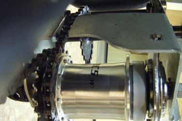
1 Information of QSRC Hubs Assembling


2 Top Right Front Left Bottom
3 Transmission General Arrangement Cog on Drive Shaft Cog on Hub Shell Cog Drive Shaft Chain to Drive Shaft Hub Chain to Crankset
4 System Moving Forward UP Front

5 System Moving Backward UP Front
6 Hub General Arrangement Detail A Gear Selector Guide Nut Detail C Detail B Nut Inside of the Gear Selector Guide Fulcrum Lever Lock washer Hub Lock washer

7 Detail A Lever end must be fastened

8 Detail B Nut Lock washer

9 Detail C Indicator Nut Fulcrum Lever Lock washer
10 Part List: QS-RC3 Three Speed Hub 2013/ Item Sales Item Sales Item Sales Description Description No. No. No. No. No. No. Description 1 HMN405 Cone Locknut-4.8t 29 HSA438 Ball Cage Assembly 49 HSL884 Cover for Short Guide Nut Black 2 HSH499 Reversible Coaster Clutch 30 HSA407 Driver Assembly HSL906 Cover for Short Guide Nut Silver 3 HSH500 Bracket for Reversible Coaster 31 HSA102 Outer Dustcap 50 HMN129 Guide Nut Standard Clutch 32 HSA284 Ball Cage Assembly R.H. 51 HSL711 Indicator Guard 4 HMB424 Screw M5*L off 33 HSL871 Plastic Sprocket Dustcap 52 HSJ943 DLS30 Shifter w/cable 5 HMW522 Spacer 2mm 34 HSL 854 Sprocket 13T(Chrome) 53 HSJ978 TSS37 Shifter w/cable 6 HSA101 Cone HSL 852 Sprocket 14T(Chrome) 54 HSJ977 TSS36 Shifter w/cable 7 HSH506 Coaster Cone Dustcap HSL 850 Sprocket 15T(Chrome) 55 HSJ939 TSS33 Shifter w/cable 8 HSH501 QS-RC Coaster Cone HSL 848 Sprocket 16T(Chrome) 56 HSJ823 SLS3N Thumb Shifter 9 HSA164 L.H. Ball Cage Assembly HSL 846 Sprocket 17T(Chrome) 57 HSJ762 SLS3C Trigger Shifter 10 HSH502 QS-RC Brake Shoes HSL 844 Sprocket 18T(Chrome) 58 HSJ963 SLS30(B-type) Shifter w/ Cable 11 HMN382 Axle Nut HSL 836 Sprocket 19T(Chrome) 59 HSJ981 SLS30(S-type) Shifter w/ Cable 12 HSH503 QS-RC Brake Actuator Drag HSL 834 Sprocket 20T(Chrome) 60 HSJ962 SLS30(T-type) Shifter w/ Cable Spring Stopper HSL 832 Sprocket 21T(Chrome) 61 HSJ995 SLS30(H-type) Shifter w/ Cable 13 HSH502 QS-RC Brake Actuator Assy. HSL 830 Sprocket 22T(Chrome) HSJ993 SLS30(P-type) Shifter w/ Cable 14 HSH504 QS-RC Brake Actuator Drag 35 HSL721 Sprocket Circlip 62 HSJ947 CLS3M Shifter Spring 36 HMN388 Dome Nut-13/32 HSJ945 CLS30 Shifter 15 HSH476 Brake Actuator HMN128 Axle Nut L.H. 63 HSL759 Cable Anchorage 16 HSH494 Brake Actuator Pawl Spring 37 HMW518 Lockwasher 4.0t 9.5mm Slot 64 HSJ553 Chainstay Fulcrum Clip ø15.9mm 17 HSH493 Brake Actuator Pawl HMW515 Lockwasher 1.8t 9.5mm Slot HSJ548 Chainstay Fulcrum Clip ø17.9mm 18 HSA836 TS/QS Hub Shell Assembly 38 HSA645 Axle 175mm HSJ753 Chainstay Fulcrum Clip ø19.1mm 19 HSA402 Planet Cage 39 HSA295 Axle Key 65 HSJ102 SLS3C Shifter Cable w/anchorage 20 HSA292 Planet Pinion 40 HSA536 Clutch & 1450mm Black Casing 21 HSA401 Pinion Pin 41 HSA128 Clutch Spring 66 HSJ802 SLS3N Shifter Cable w/anchorage 22 HSA554 Gear Ring Assembly 42 HSA129 Cap for Clutch Spring & 1400mm Black Casing 23 HSA558 Gear Ring 43 HSA420 Indicator (Mark 5) 67 HSJ887 Twist Shifter Cable w/anchorage & 24 HSA119 Pawl for Gear Ring 44 HSJ905 Fulcrum Lever w/locating Washer 1420mm Black Casing 25 HSA120 Pawl Spring 45 HMN128 L.H. Axle Nut 68 HSX172 QS-RC3 Internal Assembly 26 HSA415 Pawl Pin 46 HSA650 Gear Selector Guide 27 HSA542 Drag Spring 47 HSA620 Gear Selector Guide Full Cover 28 HSA437 Ball Ring 48 HMN420 Guide Nut Short Sun Race Sturmey-Archer Inc. No.51. Hai-Shan-Jung St., Hai-Hu Village, Lu-Ju City, Taoyuan County 338, Taiwan Tel: +886(3) , Fax: +886(3) http: // ; info@sunrace.com Sun Race Sturmey-Archer Europe Keienbergweg 79, 1101 GE Amsterdam, The Netherlands Tel: +31(20) , Fax: +31(20) http: // ; info@sunrace.nl Sun Race Sturmey-Archer USA 1436 Second Street #409, Napa, CA USA Tel: +1(707) , Fax: +1(707) http: // ; info@sunrace.com
11 Instructions for 3-speed Internal Gear Hub QS-RC3 1. GENERAL INFORMATION 1.1 Scope of this leaflet Congratulations on your purchase of a Sturmey-Archer internal gear hub. For the best performance, please follow instructions in this leaflet. Please contact your dealer if any problems are experienced with these products. Riding the gear hub out of the adjustment may cause damage to the internal parts and possible malfunction! This leaflet refers to the QS- RC3 gear hub with reverse drive. 1.2 Lubrication No routine lubrication is required. During a major service, the hub greases should be replenished or replaced especially for transmission parts of internal hub. Please contact your Sturmey-Archer dealer who is equipped to carry this out. 1.3 Gear Changing Continue pedaling, but ease pressure on the pedals and select the gear required. If the bicycle is stationary simply select gear required. 1.4 Gear Ratio 1 st Gear nd Gear rd Gear Back pedaling Pedal backwards when the vehicle has come to a standstill and then the vehicle will move backwards. Reverse gear is direct drive. It is normal that a click from inside the hub when back pedaling in gear 3.,! Do not pedal back suddenly while the vehicle is moving forward. 6. Tighten both axle nuts to 28Nm. 7. Fit the indicator rod (7) into the axle and screw it finger tight. Put the indicator cover (10) on if necessary but not snap on at this point. 8. Ensure components are fitted to the right side of axle. Unscrew the indicator by up to half a turn if necessary to ensure easy fitment over the guide unit. Connect the indicator (7A) to the cable connector (8). 2. INSTALLATION 1. Fit the sprocket (1) circlip (2) onto the hub driver. Make sure that the circlip is set in the groove of the driver completely. 2. Set the chain and internal gear hub into the frame. 3. Put the left side of the axle into the oval hole of the frame (Fig. A). Set the bracket of the reverse clutch into the hole in the bottom of the frame (Fig. B), then put the right side the axle into the slot (Fig. C) 3. GEAR ADJUSTMENT 1. Move the indicator cover (10) for easy gear adjustment. 2. Make sure that no more than 2.5mm of axle protrudes from the axle hex nut. 3. Select 2 nd gear and turn the pedal crank forward to ensure the gear is engaged. Turn the cable adjuster (9) or cable connector (8) until the end of the indicator rod is level with the end of the axle, as show in diagram. Left side Right side 4. Tighten the cable-adjusting locknut (9A) and indicator locknut (7A) to lock in adjustment. 5. Select 3 rd gear position, rotate the pedal crank, change back to 2 nd gear and check adjustment. Retry the stages above if the gear changing is not correct. 6. If there is an indicator cover (10), snap it firmly onto the guide pulley set (6). 4. BRAKE ADJUSTMENT 4. Fit the lock-washer (3) hex nut (5) on the left side of the axle. Screw the nut finger tight. 5. Locate the lock-washer (3) fulcrum lever (4) hex nut (5) and guide pulley set (6) on the right side, Do not tighten nuts at this point. Align the wheel, tension the chain and ensure the fulcrum lever (4) is parallel with the chainstay. May Sun Race Sturmey-Archer Inc.
Technical Infor m ation and Parts List. Hub Brakes (90mm) AB/C - BF/C
 AB/C - BF/C") Technical Infor m ation and Parts List Hub Brakes (90mm) AB/C - BF/C Technical Information- 90mm Hub Brakes Part 1 GENERAL INFORMATION The information contained in this manual relates specifically to the
Technical Infor m ation and Parts List Hub Brakes (90mm) AB/C - BF/C Technical Information- 90mm Hub Brakes Part 1 GENERAL INFORMATION The information contained in this manual relates specifically to the
Technical Infor m ation and Parts List. Sprinter Coaster Five Speed Hub Brake
 Technical Infor m ation and Parts List Sprinter Coaster Five Speed Hub Brake Part 1 GENERAL INFORMATION 1.1 SCOPE OF THIS LEAFLET Congratulations upon your purchase of a Sturmey-Archer SPRINTER COASTER
Technical Infor m ation and Parts List. Sprinter and Sprinter Elite Five Speed Hubs
 Technical Infor m ation and Parts List Sprinter and Sprinter Elite Five Speed Hubs Part 1 GENERAL INFORMATION 1.1 SCOPE OF THIS LEAFLET Congratulations upon your purchase of a Sturmey-Archer SPRINTER 5-SPEED
Elite Alloy Hub Brakes
 Technical Infor m ation and Parts List Elite Alloy Hub Brakes V T - ST - AT 3 Technical Information- Elite Alloy Hubs Part 1 GENERAL INFORMATION Fig. 1 - Gear Adjustment Fig. 2 HMN 132 The information
~ ~j)~~ @) A WC (after 5/91) STURMEY ARCHER 3 SPEED COASTER BRAKE S3C
~~ @) A WC (after 5/91) STURMEY ARCHER 3 SPEED COASTER BRAKE S3C") STURMEY ARCHER 3 SPEED COASTER BRAKE A WC (after 5/91) ~ ~j)~~ @@ ~~@~~ @) @@ S3C «~ @OOlQj@l~ 'The lockwasher, brake arm nut and brake arm as a unit may be interchanged. 2Same as AW. 3HSA 469 replaces
STURMEY ARCHER 3 SPEED COASTER BRAKE A WC (after 5/91) ~ ~j)~~ @@ ~~@~~ @) @@ S3C «~ @OOlQj@l~ 'The lockwasher, brake arm nut and brake arm as a unit may be interchanged. 2Same as AW. 3HSA 469 replaces
Introduction. The Original And Best Since 1902
 Introduction The Original And Best Since 1902 For 114 years, Sturmey-Archer have been pioneers in the design and manufacture of internal gear hubs, hub brakes and dynohub lighting. This is a history of
1 HR-301/D Parts Manual. Table Of Contents
 Table Of Contents 301/D Parts Manual 3 Point Hitch...2 Pull-Type Hitch...4 Main Frame...6 Angle Adjuster - Serial Number 44982 & Prior...8 Rotor Assembly - Serial Number 44982 & Prior...10 Rotor Assembly
1 RS-300/D 320/D 340/D 350H Parts Manual
 300/D 320/D 340/D 350H Parts Manual Table Of Contents Three Point Hitch / Hitch Frame Assembly... 3 Tongue Pull Hitch Assembly... 7 Main Gearbox... 11 Crank Handle & Gear... 13 Hydraulic Lift... 15 Rotor
CK-5000T Metropolis Patterson Transmission Crankset Installation Instructions Published Jul, ZSP001.v3 Full Speed Ahead
 CK-5000T Metropolis Patterson Transmission Crankset Installation Instructions Published Jul, 2011. ZSP001.v3 Full Speed Ahead Introduction Congratulations on your Full Speed Ahead product. Please read
MailStar Maintenance and Adjustment March 2002
 MailStar Maintenance and Adjustment March 2002 The MailStar bicycle incorporates many new features to ease maintenance and improve handling and performance. The majority of components are similar to those
1 KW-550T Parts Manual. Table Of Contents
 KW-550T Parts Manual Table Of Contents Drawbar... 2 Central Gearbox - Serial No. 523800-554988... 4 Central Gearbox - Serial No. 523800-554988... 6 Central Gearbox - Serial No. 554989-... 8 Central Gearbox
SERVICE SHEET No. 515
 SERVICE SHEET No. 515 MODEL D7 DISMANTLING AND REASSEMBLY OF HUBS AND BRAKES Both wheels are fitted with ball journal bearings which do not require adjustment. The bearings are packed with grease during
MODEL S-32, 3200, ALL AMERICAN
 MODEL S-32, 3200, ALL AMERICAN 1. 1 3201-7001 Chassis Weldment 2. 1 3204-7010 Bell Crank Weld 3. 1 3204-7009 Seconday Lift Weld 4. 1 3204-2018 Primary Lift Arm 6. 1 340-3025-S0 Seat Spring 6. 3 847-2803
Specification Item Number / Model Name CK-5001T / Metropolis Patterson Transmission Crankset
 CK-5001T Metropolis Patterson Transmission Crankset Installation Instructions Published May, 2015. ZSP001.v4 Full Speed Ahead Introduction Congratulations on your Full Speed Ahead product. Please read
62 Deck Idler Kit High Speed
 Part No. 00 FORM NO. -899 6 Deck Idler Kit High Speed For Model 70 Serial No. 99000 to 99000 For Model 7 Serial No. 9900 to 99000 INSTALLATION INSTRUCTIONS Loose Parts Note: Use the chart below to identify
CONTENTS GEAR HUB SYSTEMS
 CONTENTS GEAR HUB SYSTEMS GEAR HUBS AND SHIFTERS DualDrive Spectro S7 Spectro P CARGO Spectro P Cargo 9 Spectro T 7 Sparc SPECTRO SYSTEM COMPONENTS i-brake Two-Axis Brake Lever SmartBar Power Chain 7 SUPPORT
HUDSON CHASSIS PARTS LIST
 1940-1951 HUDSON CHASSIS PARTS LIST 5 HUDSON CHASSIS PARTS - 1940-1951 Front Suspension See Fig. 1 1 - Upper Support Arm & Pivot Assembly 159728-1940, 1941, first type 1942 (forged piece) (R.H.). 159729-1940,
PARTS CATALOGUE. Rockford Motors inc.
 PARTS CATALOGUE Rockford Motors inc. INSTRUCTIONS FOR USING THE PARTS CATALOGUE 1. This catalogue covers all the items of genuine parts and tools of BRIDGESTONE 350 GTR and 350 GTO motorcycles. 2. Please
DM-SG (English) Dealer s Manual. Nexus. Inter-8 Inter-7 Inter-5
 Dealer s Manual. Nexus. Inter-8 Inter-7 Inter-5") (English) DM-SG0003-06 Dealer s Manual Nexus Inter-8 Inter-7 Inter-5 CONTENTS MODELS COVERED BY THIS DEALER S MANUAL...4 IMPORTANT NOTICE...5 TO ENSURE SAFETY...6 LIST OF TOOLS TO BE USED...12 INSTALLATION...14
(English) DM-SG0003-06 Dealer s Manual Nexus Inter-8 Inter-7 Inter-5 CONTENTS MODELS COVERED BY THIS DEALER S MANUAL...4 IMPORTANT NOTICE...5 TO ENSURE SAFETY...6 LIST OF TOOLS TO BE USED...12 INSTALLATION...14
REPAIR PARTS SNOW THROWER -- MODEL NUMBER PR5524ESNHL ( ) AUGER HOUSING / IMPELLER ASSEMBLY
 AUGER HOUSING / IMPELLER ASSEMBLY") REPAIR S SNOW THROWER -- MODEL NUMBER PRESNHL (9900700) AUGER HOUSING / IMPELLER ASSEMBLY 7 0 7 9 0 9 7 0 (EXPLODED) 9 0.07.00-B NOTE: All component dimensions given in U.S. inches. inch =. mm 0 REPAIR
REPAIR S SNOW THROWER -- MODEL NUMBER PRESNHL (9900700) AUGER HOUSING / IMPELLER ASSEMBLY 7 0 7 9 0 9 7 0 (EXPLODED) 9 0.07.00-B NOTE: All component dimensions given in U.S. inches. inch =. mm 0 REPAIR
Chain Box and Knife. Item # Description Part Number 180-D & GS
 Chain Box and Knife Item # Description Part Number 180-D & GS 1 Groove pin 2275-03160 2 Hex cap screw 2175-03061 3 Washer 2275-03060 4 Setscrew 2175-07163 5 Chain box 4975-00355 6 Berkel logo 3175-00152
Double Master Plus Combine
 Pickup Head Section 3 Pickup Head Straight Pull (2001 20)... 2-7 Pickup Head DMP SP2 (2006 2008)... 8-10 Pickup Head DMP SP2 (20 2014)... 11-13 Pickup Head DMP & DMP SP (2010 2014)... 14-16 Pickup Head
SPARE PARTS LIST POLE PRUNER/POLE SAWS 327 P4
 SPARE PARTS LIST POLE PRUNER/POLE SAWS ACCESSORIES ACCESSORIES Ref Part No Description Remark QTY KIT 1 537 04 07-10 ACCESSORY BAG 1 2 501 69 17-01 COMBINATION WRENCH 1 3 502 21 58-01 WRENCH 1 4 503 97
1. Remove the parking brake assembly. 2. Remove the 4 bolts holding the yoke flange and drum. Remove the yoke flange and drive.
 Disassembly NOTE: To replace the brake assembly, brake shoe and lining assemblies, or other operational components the complete parking brake assembly must be removed from the vehicle. 1. Remove the parking
MODEL NUMBER ST230E PRODUCT NUMBER MFG. ID. NUMBER
 ILLUSTRATED PARTS LIST MODEL NUMBER ST0E PRODUCT NUMBER 0000 MFG. ID. NUMBER 00-0 - AUGER HOUSING / IMPELLER ASSEMBLY SNOW THROWER - MODEL NO. ST0E (0000), PRODUCT NO. 00-0 0 0 (EXPLODED) 0.0.0-F NOTE:
B B B
 FIG CYLINDER Suzuki Worldwide Motorcycle-ATV Page: of -0B00-00 0-00 0-000 0-00 0-0B0-0B0 0-0 0-0 Head, Cylinder Gasket, Cylinder Head Spark Plug (ngk,bphs) Spark Plug (nd,wfp-u) Cylinder Gasket, Cylinder
CYLINDER - CRANKCASE. Ref. Part No. Number Description Qty Remarks
 A1 CYLINDER - CRANKCASE 1 (374-15111-00-00) CRANKCASE 1............ 1 2 374-15121-02-00 CRANKCASE 2............ 1 3 99510-12016-00 PIN, DOWEL.............. 2 4 98580-06550-00 SCREW PAN HEAD (92503-06050).............
Printed from CyberCat-STIGA Section: GARDEN ELECTRICAL SYSTEM
 Section: GARDEN ELECTRICAL SYSTEM Section: GARDEN ELECTRICAL SYSTEM 2312 2333 1 1 1134-3625-01 Harness 2 1 1134-3623-02.Interlock module 4 2 9849-8013-16 Screw 5 2 1134-3132-01 Cable holder 6 2 1134-3204-01
AllCropHarvester.com. New/New Old Stock List as of 03/04/2016
 AllCropHarvester.com New/New Old Stock List as of 03/04/2016 If your part is not listed, please contact us. We may be able to get it, and/or have it as a used part. Contact us for prices not listed/used.
SPARE PARTS LIST. POLE PRUNER/POLE SAWS 327 P5x
 SPARE PARTS LIST POLE PRUNER/POLE SAWS ACCESSORIES ACCESSORIES Ref Part No Description Remark QTY KIT 1 537 04 07-10 ACCESSORY BAG 1 2 501 69 17-01 COMBINATION WRENCH 1 3 502 21 58-01 WRENCH 1 4 503 98
1. General Description
 1. General Description A: SPECIFICATION 1. MANUAL TRANSMISSION AND FRONT DIFFERENTIAL Type Transmission gear ratio Front reduction gear Rear reduction gear Front differential Center differential Final
CONVERSION KIT. User Manual AKLO. English. Please read through carefully before beginning your conversion
 CONVERSION KIT User Manual AKLO English Please read through carefully before beginning your conversion INSTALLATION PROCESS Before beginning your conversion, there are a couple things you can do that will
SPARE PARTS LIST RIDERS RIDER 111 B, , , , ,
 SPARE PARTS LIST RIDERS RIDER 111 B, 965996801, 965996885, 966663185, 967186501, 2011-02 CHASSIS & ENCLOSURES RIDER 111 B, 965996801, 965996885, 966663185, 967186501, 2011-02 CHASSIS & ENCLOSURES RIDER
PARTS LISTING a WR
 7 CRT 3 2.1 PARTS LISTING 54140066a WR 02-1- HANDLE ASSEMBLY 1 711100 Screw, Pan Hd. #10-24 UNC 2 53212656 Panel, Control 3 532104164 Tie, Cable 4 53212477 Grip, Handle 5 5321247 Clip, Hairpin 6 5320132
Eye-bolt for front chain adjustment, Pre-49 singles, twins, 1958-on CS singles
 Part No. AJS & MATCHLESS GEARBOX & CLUTCH - NEW PARTS Price (20% VAT) Price (excl VAT) Tool for adjusting clutch spring nuts (heavier duty than 017254 spanner) 5.00 4.17 017254 Spanner, single end, dynamo
PARTS LIST. BRC Racing BRC 250 FE SERIAL NO: BRC Racing
 BRC Racing PARTS LIST BRC 20 FE SERIAL NO: BRC Racing A Division of BRC Engineering Ltd. # - 2nd Ave NE Calgary, Alberta Canada T2E S1 Tel: 0-21-00 Fax: 0-21-0 Web: www.brceng.com RELEASE DATE: 01-200
Spare Parts B WR
 7 CRT 52 1.1997 Spare Parts 954 14 00-20B WR 01-07-98 HANDLE ASSEMBLY 1 871191008 Screw, Phd. #10-24 UNC 2 532126956 Panel, Control 3 532104164 Tie, Cable 4 532124797 Grip, Handle 5 532124788 Clip, Hairpin
Ilustrated Parts List
 Spicer Drive Axles Ilustrated Parts List Spicer All Wheel 4 x 4 Drive System AXIP-0400 November 1999 Page to Insert The Spicer 4x4 Drive System Axle models and other equipment covered in this publication
INSTRUCTIONS. Disassembly. Shifter Cam Assembly. Shifter Forks
 INSTRUCTIONS Disassembly To protect against accidental start-up of vehicle, always disconnect the negative battery cable before working on the motorcycle. Failure to disconnect the battery cable could
Main Frame (1,676 MM (5-1/2 FT.) Hay Pickup)
 Hay Pickup)") Main Frame (,676 MM (5-/2 FT.) Hay Pickup) 2 E34250 STRIPPER 2-3000 AUGER E66297 ANGLE 2 300- AUGER, (SUB FOR E34496) (SUB E9572) E9572 ANGLE 2 AUGER E6905 TUBE 59400-86 Pickup Heads Strippers (,676 MM
Main Frame (,676 MM (5-/2 FT.) Hay Pickup) 2 E34250 STRIPPER 2-3000 AUGER E66297 ANGLE 2 300- AUGER, (SUB FOR E34496) (SUB E9572) E9572 ANGLE 2 AUGER E6905 TUBE 59400-86 Pickup Heads Strippers (,676 MM
I Illustrated Parts List CRT B. Tiller. Repair Parts Manual
 Illustrated Parts List 15-12 I502012 CRT 1 54001152B Repair Parts Manual Tiller HANDLE ASSEMBLY 1 711100 Screw, Pan Hd. #10-24 UNC 2 53212656 Panel, Control 3 532104164 Tie, Cable 4 53212477 Grip, Handle
MT (10/19/07) Rev. 02 PARTS MANUAL
 Rev. 02 PARTS MANUAL") MT1741210 (10/19/07) Rev. 02 PARTS MANUAL Table Of Contents PRODUCT COMPONENTS PAGES Engine... 4 Frame... 6 Drive... 8 Auger Housing... 10 Discharge Chute... 12 Handle Assembly... 14 Shift Yoke... 16
MT1741210 (10/19/07) Rev. 02 PARTS MANUAL Table Of Contents PRODUCT COMPONENTS PAGES Engine... 4 Frame... 6 Drive... 8 Auger Housing... 10 Discharge Chute... 12 Handle Assembly... 14 Shift Yoke... 16
REPAIR PARTS SNOW THROWER - - MODEL NO. PR827ES ( ) AUGER HOUSING / IMPELLER ASSEMBLY
 AUGER HOUSING / IMPELLER ASSEMBLY") REPAIR PARTS SNOW THROWER - - MODEL NO. PR8ES (00000) AUGER HOUSING / IMPELLER ASSEMBLY (x) (x) 0.0.00-A 0X8 AUGER HOUSING 0X SCRAPER BAR 00 CARRIAGE BOLT / 8 X. NUT / 8 0.0.0-B 08 AUGER BEARING BEARING
REPAIR PARTS SNOW THROWER - - MODEL NO. PR8ES (00000) AUGER HOUSING / IMPELLER ASSEMBLY (x) (x) 0.0.00-A 0X8 AUGER HOUSING 0X SCRAPER BAR 00 CARRIAGE BOLT / 8 X. NUT / 8 0.0.0-B 08 AUGER BEARING BEARING
Illustrated Parts List / / 924 SB
 9SB Illustrated Parts List / 990000 / 9 SB AUGER HOUSING / IMPELLER ASSEMBLY SNOW THROWER - MODEL 9SBb (990000), PRODUCT 9 9 00-0 9 0 9 0 (EXPLODED) 9 0.0.00-B NOTE: All component dimensions given in U.S.
Spearhead STARCUT 500 STARCUT 500. Edition Jan 2013 Post Serial No. S Part No
 STARCUT 500 Edition 2.0 - Jan 2013 Post Serial No. S136498 Part No. 8999040 1 Contents Ordering Your Parts 3 Centre Section 4 Wing Section 6 Centre Axle 8 Wing Axle 10 Std Drawbar 12 Tie-Bar Assembly 14
Owner and Parts Manual for
 ( ( Speedex Owner and Parts Manual for Model 832 Tractor Speedex Tractor Company ,/' Sheet Metal Group Hood 3439-7502 2 Model 832 Decal 42-0832 2 3 Speedex Script Decal 42-04 2 4 '/4-20 Locknut 99-2600
PARTNER 5.5 HP 17" REAR TINE TILLER MODEL NO. 511 (PRT5N)
") ILLUSTRATED PARTS BREAKDOWN PARTNER 5.5 HP 17" REAR TINE TILLER MODEL NO. 511 (PRT5N) 954 00 13-81 171280 1.3.00 TR HANDLES 1 532127012 Throttle, Control 2 532141406 Grip, Handle 3 532110673 Grommet, Handle
ILLUSTRATED PARTS BREAKDOWN PARTNER 5.5 HP 17" REAR TINE TILLER MODEL NO. 511 (PRT5N) 954 00 13-81 171280 1.3.00 TR HANDLES 1 532127012 Throttle, Control 2 532141406 Grip, Handle 3 532110673 Grommet, Handle
ILLUSTRATED PARTS LIST MODEL NUMBER 14527E PRODUCT NUMBER MFG. ID. NUMBER
 ILLUSTRATED S LIST MODEL NUMBER E PRODUCT NUMBER 00- MFG. ID. NUMBER 000 0 0 - AUGER HOUSING / IMPELLER ASSEMBLY SNOW THROWER - MODEL E (000), PRODUCT 00-0 0 0 (EXPLODED) 0.0.0-F NOTE: All component dimensions
Edition October 2014 Part No
 Edition 1.3 - October 2014 Part No. 8999076 1 Contents Ordering Your Parts... 3 Centre Section - S180025.70... 5 Wing Section - S180025.71/72...7 Centre Axle - S180025.110... 9 Wing Axle - S180025.111...10
1 KW-880 Parts Manual
 Headstock... 2 Hitch Beam... 4 Central Gearbox... 6 Central Gearbox... 8 Intermediate Beam... 10 Intermediate Beam... 12 Intermediate Beam Outside... 14 Intermediate Beam Outside... 16 Outer Support Tube...
REPLACEMENT TP LT-R
 REPLACEMENT PARTS FACTORY CUSTOMER MODEL: 552544 MODEL: 385002x190A 1740360 Table Of Contents PRODUCT COMPONENTS PAGES Steering... 4 Engine Mount... 6 Motion Drive... 8 Electrical System... 12 Chassis
MODEL NUMBER 11524E PRODUCT NUMBER MFG. ID. NUMBER
 ILLUSTRATED PARTS LIST MODEL NUMBER E PRODUCT NUMBER 000 MFG. ID. NUMBER 00-0 0 - AUGER HOUSING / IMPELLER ASSEMBLY SNOW THROWER - MODEL NO. E (000), PRODUCT NO. 00-0 0 0 (EXPLODED) 0.0.0-F AUGER HOUSING
SPARE PARTS BOOK Ride-on mower with front-mounted, mulching cutter deck GTM 1350DL
 SPARE PARTS BOOK Ride-on mower with front-mounted, mulching cutter deck GTM 1350DL 1 GTM1350 REMARKS ON THIS SPARE PARTS CATALOGUE * This spare part catalogue contains all spare parts for the GTM1350
MODEL NUMBER 14527SB-LS PRODUCT NUMBER MFG. ID. NUMBER
 ILLUSTRATED S LIST MODEL NUMBER SB-LS PRODUCT NUMBER 9 9 00-9 MFG. ID. NUMBER 9900900 009-0 -90 Rev. 0.09.09 SR AUGER HOUSING / IMPELLER ASSEMBLY SNOW THROWER - MODEL SB-LS (9900900), PRODUCT 9 9 00-9
G85CS Parts list. Frank Kyul, Netherlands
 G85CS Parts list Frank Kyul, Netherlands http://home.wanadoo.nl/fxkuyl/ CYLINDER BARREL & HEAD 022298 Barrel Cylinder 1 022515 Washer Cylinder Base 1 015351 Nut. Sleeve Cylinder Head 4 042157 Washer Sleeve
cc Fun Kart. Illustrated Parts Manual RECOMMENDED MINIMUM OPERATOR AGE: 12
 Illustrated Parts Manual 6150 150cc Fun Kart RECOMMENDED MINIMUM OPERATOR AGE: 12 THIS VEHICLE IS FOR OFF-ROAD USE ONLY THIS VEHICLE IS NOT DESIGNED FOR USE ON RENTAL TRACKS OR RACING BEFORE OPERATING
SPARE PARTS LIST FRONTRIDERS FR2312 MA, , ,
 SPARE PARTS LIST FRONTRIDERS FR2312 MA, 966639801, 966639885, 2011-02 CHASSIS & ENCLOSURES FR2312 MA, 966639801, 966639885, 2011-02 CHASSIS & ENCLOSURES FR2312 MA, 966639801, 966639885, 2011-02 Ref Part
Reproduction. Not for. Mid Frame Dual Stage Snowthrower. Parts Manual
 Parts Manual Attachment Mfg. No. Description 1695994 (I924EX), 9TP 24" Snowthrower (CE/Export) Mid Frame Dual Stage Snowthrower Not for Reproduction Manual Part No. Revision - Rev. Date: 7/20/2011 Table
PARTS MANUAL FOR R22N/H REAR AXLE
 PARTS MANUAL FOR REAR AXLE MARMON-HERRINGTON ALL-WHEEL DRIVE 13001 Magisterial Drive Louisville, KY 40223 TABLE OF CONTENTS REPLACEMENT PARTS & WARRANTY CLAIM PROCEDURE......... 3 DIFFERENTIAL CARRIER
REAR AXLE PARTS.BOOK SS-842 DATE: SPICER PS-7036 AXLE USED WITH PS-1350 AXLE STEERING CYLINDER & steering CYLINDER
 :. :. :. - I _ REAR AXLE PARTS.BOOK SS-8 o DATE: 7--9 SPICER PS-703 AXLE USED WITH PS-350 AXLE 7-9-30 STEERING CYLINDER & 7-9-3 steering CYLINDER o BARAGA PRODUCTS, INC. 55 N. Superior AYe. Baraga. Ul
250P Manure Spreader
 0P Manure Spreader Illustrated Parts Breakdown Page - Page Page Page Page Page Page Page Page Page Page Page Page Page Page - Page Page Page 0 Complete Front End PTO/Jack/Hitch Assembly Front Pulley Assembly
Spearhead Trident Trident 6000 Flail Mower
 Trident 6000 Flail Mower 8999094 Edition 1.0 May 2015 1 Contents Ordering Your Part s 3 S180015.130 Main Frame Assy - Mounted 4 S180015.131 Rear Linkage Assy 6 S180015.132 Trident 6000 LH Wing Arm Assy
CYLINDER HEAD CONTINUED ON NEXT FRAME. Ref. Part No. Number Description Qty Remarks
 A1 A2 A3 A4 CYLINDER HEAD 1 3TB-11101-02-00 CYLINDER HEAD ASSY...... 1 2 4H7-11133-10-00. GUIDE, INTAKE VALVE..... 4 3 93440-12052-00. CIRCLIP................. 4 4 90116-06475-00. BOLT, STUD.............
TION AND OPERATION Procedure revision date: 01/22/1999
 TION AND OPERATION Procedure revision date: 01/22/1999 Main Components and Functions AX4S Main Components http://www.fordtechservice.dealerconnection.com/pubs/content/~wsww/~mus~len/20/sww71006.htm (1
MODEL NUMBER 12527HV PRODUCT NUMBER MFG. ID. NUMBER
 ILLUSTRATED S LIST MODEL NUMBER HV PRODUCT NUMBER 00- MFG. ID. NUMBER 000 0 - Rev REPAIR S AUGER HOUSING / IMPELLER ASSEMBLY SNOW THROWER - MODEL HV (000), PRODUCT 00-0 0 0 (EXPLODED) 0.0.0-F NOTE: All
Speedex Owner and Parts Manual for
 Speedex Owner and Parts Manual for S'---.. Model 1631 Tractor Speedex Tractor Company Frame Group Item Description 1. FrameWeldment 2. 3/8"-16"xl W' Hx. Hd. CpoScrew 3. 3/8-16" Hex Nut 4. 3/8" Lock Washer
Reproduction. Not for. Walk Behind Mowers 19" & 21" Parts Manual. Attachments
 Parts Manual Attachments Walk Behind Mowers 19" & 21" Mfg. No. Description 881633 ESPV19875EXAL, 19" Self Propelled Walk Mower (Export) 881634 ESPV21875EXAL, 21" Self Propelled Walk Mower (Export) Manual
PR6R24 ILLUSTRATED PARTS LIST MODEL NUMBER: SNOW THROWER
 IMPORTANT MANUAL Do Not Throw Away ILLUSTRATED S LIST MODEL NUMBER: PRR SNOW THROWER WARNING: Read the Owner's Manual and fol low all Warnings and Safety In struc tions. Fail ure to do so can result in
MODEL NUMBER 1830HV PRODUCT NUMBER MFG. ID. NUMBER
 ILLUSTRATED S LIST MODEL NUMBER 0HV PRODUCT NUMBER 00- MFG. ID. NUMBER 000 0 0-0 AUGER HOUSING / IMPELLER ASSEMBLY SNOW THROWER - MODEL 0HV (000), PRODUCT 00-0 0 0 (EXPLODED) 0.0.0-F NOTE: All component
CYLINDER HEAD CONTINUED ON NEXT FRAME. Ref. Part No. Number Description Qty Remarks
 A1 A2 A3 A4 CYLINDER HEAD 1 3TB-11101-02-00 CYLINDER HEAD ASSY...... 1 2 4H7-11133-10-00. GUIDE, INTAKE VALVE..... 4 3 93440-12052-00. CIRCLIP................. 4 4 90116-06475-00. BOLT, STUD.............
CYLINDER HEAD CONTINUED ON NEXT FRAME. Ref. Part No. Number Description Qty Remarks
 A1 CYLINDER HEAD 1 4JY-11111-00-00 HEAD, CYLINDER 1 (4JY-11111-01-00).......... 1 2 90116-08394-00 BOLT, STUD.............. 5 3 90176-08026-00 NUT, CROWN............. 5 4 90201-08087-00 WASHER, PLATE...........
Technical Support (707)
") Installation Instructions CONSOLE MEGASHIFTER Fits: 1982-1992 Camaro & Firebird w/automatic Transmission *except 1988-1992 Firebird Formula Model Catalog # 80692 WORK SAFELY! For maximum safety, perform
Installation Instructions CONSOLE MEGASHIFTER Fits: 1982-1992 Camaro & Firebird w/automatic Transmission *except 1988-1992 Firebird Formula Model Catalog # 80692 WORK SAFELY! For maximum safety, perform
REPAIR PARTS SNOW THROWER - MODEL NUMBER AUGER HOUSING / IMPELLER ASSEMBLY
 REPAIR PARTS SNOW THROWER - MODEL NUMBER 0000 AUGER HOUSING / IMPELLER ASSEMBLY 3 7 8 7 3 37 7 38 7 0 3 3 7 8 33 8 3 3 3 0 3 8 3 8 0 7 7 30 8 0 7 38 REPAIR PARTS SNOW THROWER - MODEL NUMBER 0000 AUGER
=-=-===~-~", Speedex. Owners and Parts Manual for. Model 1732
 -------------=-=-===~-~", Speedex Owners and Parts Manual for Model 1732 FRONT END tem Description Part No. 1. 4 x 12 tire 0041-2412 2. 4 x 12 tube 0041-1412 3. 1/2 x 20 cone nut 0914-3500 4. 4x 12 rim
IPL, ST276 EP, , ST276 EP
 IPL, ST EP, 00, 0- ST EP Spare parts Ersatzteile Pièces détachées Reserve onderdelen Repuestos Reservdelar AUGER HOUSING / IMPELLER ASSEMBLY 0 0 (EXPLODED) 0.0.0-D NOTE: All component dimensions given
AmTryke Adult Recumbent Model JT2000 #50-FC-2000
 AmTryke Adult Recumbent Model JT2000 #50-FC-2000 TOOLS Needed for Assembly 5 mm Allen Wrench 8 mm Socket or Wrench 10 mm Socket or Wrench 14 mm Socket or Wrench 15 mm Socket or Wrench 22 mm Socket or Adjustable
One Step Rod Cutter Rear Pull
 One Step Rod Cutter Rear Pull Drivelines Section 13 Model Years 1988 1991 (Secondary Driveline) 1 Solid Shaft... 2-5 Model Years 1988 1992 (Primary Driveline) G & G... 6-11 Model Year 1992 (Secondary Driveline)
ILLUSTRATED PARTS LIST MODEL NUMBER 15530SB-LS PRODUCT NUMBER MFG. ID. NUMBER TH
 ILLUSTRATED PARTS LIST MODEL NUMBER SB-LS PRODUCT NUMBER 00- MFG. ID. NUMBER 000-0.0.0 TH AUGER HOUSING / IMPELLER ASSEMBLY 0 0 (EXPLODED) 0.0.0-C NOTE: All component dimensions given in U.S. inches. inch
Bag 1. Bag 1. Center Pivot. Center Pivot
 8 00734 01901 5 Center Pivot Bag 1 3374 - Center Pivot Socket 4019 - Alum Pivot ball 3254-2-56 Button Head *Note - Sometimes it is helpful to slightly over-tighten the top clamp screws, then work the ball
Sharpener Assembly Parts List
 Sharpener Assembly Parts List Item Description Part Number sharpener assy. w/o cover 4675-00851 N/S sharpener assy. w/ cover assy. no upper guard 4675-00853 **sharpener assy. w/ cover assy. & upper guard
CYLINDER HEAD CONTINUED ON NEXT FRAME. Ref. Part No. Number Description Qty Remarks
 A1 CYLINDER HEAD 1 4JY-11111-00-00 HEAD, CYLINDER 1 (4JY-11111-01-00).......... 1 2 90116-08394-00 BOLT, STUD.............. 5 3 90176-08026-00 NUT, CROWN............. 5 4 90201-08087-00 WASHER, PLATE...........
Parts List. Model Revision 00 TP LT-R
 Parts List Model 7800276 Revision 00 Rev. Date 03/2008 Table Of Contents PRODUCT COMPONENTS PAGES Steering... 4 Engine Mount... 6 Motion Drive... 8 Electrical System... 12 Chassis & Hood... 14 Decals...
Suggested Spares Guide
 Suggested Spares Guide 380 Side Feed Baler Module 14, 15, 16 Chambers A Product of Sherwood, Oregon USA Rev: 11-2013 Section 1 - Front End HTH0021097 Hitch 1 HTH0031000 Hitch Ball W/Nut & Washer 1 F000000440
ROTARY TILLER. Operation, Service & Parts Manual For "AS" Series. FORM: ASTillerBook.QXD
 ROTARY TILLER Operation, Service & Parts Manual For "AS" Series FORM: ASTillerBook.QXD April 2002 TABLE OF CONTENTS Preparation......................................1 Assembly Instructions.............................2
DOMESTIC ROTARY MOWERS. Part Numbers Maxicut SP Combo Quantum XTE 55i Maxicut SP Combo H Honda GCV 160. From Serial Number
 Issue A October 2002 REF # 783903 DOMESTIC ROTARY MOWERS Part Numbers 983903 Quantum XTE 55i 983904 H Honda GCV 160 From Serial Number 1297215 Month and Year of Manufacture: November 2001 Issue A October
1822-I/1822-IC. Spindle Assembly. Pipe & Bolt Threading Machine. Ridge Tool Company/Elyria, Ohio, U.S.A. 2* 3 4 5* *
 -I/-IC Spindle Assembly * * * 0 * * * 0 * * 0* * * Rear Cover * Screw () * Washer () Top Cover w/clips (Includes,, ) * J Clip () Front Cover * Screw () Pivot Rod Support () Pivot Rod () 0 Shoulder Screw
 Page 1 of 22 SECTION 307-01: Automatic Transaxle/Transmission 4R70E/4R75E ASSEMBLY Procedure revision date: 05/29/2009 Transmission Printable View (1554 KB) Special Tool(s) Air Test Plate, Transmission
Brake System H TX, H2.0TXS [B475]; H TX [B466] Safety Precautions Maintenance and Repair
![Brake System H TX, H2.0TXS [B475]; H TX [B466] Safety Precautions Maintenance and Repair](/thumbs/86/93834005.jpg "Brake System H TX, H2.0TXS [B475]; H TX [B466] Safety Precautions Maintenance and Repair") HMM180001 Brake System H1.5-1.8TX, H2.0TXS [B475]; H2.5-3.5TX [B466] Safety Precautions Maintenance and Repair When lifting parts or assemblies, make sure all slings, chains, or cables are correctly fastened,
HMM180001 Brake System H1.5-1.8TX, H2.0TXS [B475]; H2.5-3.5TX [B466] Safety Precautions Maintenance and Repair When lifting parts or assemblies, make sure all slings, chains, or cables are correctly fastened,
SERIES DOMESTIC ROTARY MOWERS. Part Numbers Maxicut SP Quantum XTE Maxicut SP H Honda GCV 160. From Serial Number
 Issue A February 2001 IPL Part # 782614 DOMESTIC ROTARY MOWERS Part Numbers 982614 Quantum XTE 55 982642 H Honda GCV 160 From Serial Number 1159000 Issue A February 2001 IPL Part # 782614 H Determine right
CYLINDER HEAD CONTINUED ON NEXT FRAME. Ref. Part No. Number Description Qty Remarks
 A1 CYLINDER HEAD 1 15A-11110-01-00 CYLINDER HEAD ASSEMBLY. 1 2 93440-10085-00. CIRCLIP................. 2 3 90153-06045-00. SCREW, HEXAGON........ 1 4 90430-06014-00. GASKET................ 1 5 5H0-11133-10-00.
Reproduction. Not for. Mid Frame Dual Stage Snowthrowers. Parts Manual
 Parts Manual Attachment Mfg. No. Description 1695821 (I1224E), 11.5TP 24" Dual Stage Snowthrower 1695842 (I924EX), 9TP 24" Snowthrower (CE/Export) Mid Frame Dual Stage Snowthrowers Not for Reproduction
TRANSFER CASE Mitsubishi Montero APPLICATION DESCRIPTION TESTING 4WD INDICATOR CONTROL UNIT (MONTERO) DETECTION SWITCH
 DETECTION SWITCH") TRANSFER CASE 1993 Mitsubishi Montero 1991-94 TRANSFER CASES Mitsubishi Dodge; Ram-50 Mitsubishi; Pickup, Montero APPLICATION TRANSFER CASE APPLICATIONS TABLE Application (1) Transmission Model Dodge 1991-93
TRANSFER CASE 1993 Mitsubishi Montero 1991-94 TRANSFER CASES Mitsubishi Dodge; Ram-50 Mitsubishi; Pickup, Montero APPLICATION TRANSFER CASE APPLICATIONS TABLE Application (1) Transmission Model Dodge 1991-93
PR624ES OWNER'S MANUAL MODEL NUMBER: SNOW THROWER
 IMPORTANT MANUAL Do Not Throw Away OWNER'S MANUAL MODEL NUMBER: PRES SNOW THROWER WARNING: Read the Owner's Manual and fol low all Warnings and Safety In struc tions. Fail ure to do so can result in serious
Tel/Fax: Replacement parts for : MULTI 1210, 1250OS, 1250W, 1250N, 1250DOM.
 Replacement parts for : MULTI 1210, 1250OS, 1250W, 1250N, 1250DOM., 1215CD, VARIABLE SPEED PULLEY 1250 O.S. - 1/2 Shaft P-1629 1250 N.S. - 5/8 Shaft P-1649 V-BELTS 35 Motor to printing head P-4904 33 Pump
FX140 & FX140R Skidding Winch Parts Manual
 EMB Manufacturing Inc. 4144 Boomer Line St. Clements, On N0B 2M0 Canada Ph: (519) 699-9283 Fax: (519) 699-4146 www.wallensteinequipment.com FX140 & FX140R Skidding Winch Parts Manual S/N 514094 & After
XT11530ES ILLUSTRATED PARTS LIST MODEL NUMBER: SNOW THROWER
 IMPORTANT MANUAL Do Not Throw Away ILLUSTRATED S LIST MODEL NUMBER: XT0ES SNOW THROWER WARNING: Read the Owner's Manual and fol low all Warnings and Safety In struc tions. Fail ure to do so can result
Model Series E6A5E, E645E & E665E
 Model Series EAE, EE & EE 0. -0 Housing R.H. -0 Housing L.H.. 0-0 Hex Screw /- x.. -0A Spiral Axle -00A Spiral Axle. -0 Key. -0 Pin-Spiral. -0 Shaft-Worm. -0 Gear-Worm. -0 Collar-Thrust. -0 Plug 0. -0
Printed from CyberCat-STIGA Section: VILLA ACCESSORY BAG
 Section: VILLA ACCESSORY BAG Section: VILLA ACCESSORY BAG Pos. Quantity Spare part No Description Kit Notes New 2721 2722 2723 2724 0 1 1134-4664-01 Accessory bag assy 1 1 9595-0262-00.Locating pin 2A
Fichtel and Sachs Old Torpedo Duomatic Re-assembly
 Fichtel and Sachs Old Torpedo Duomatic Re-assembly Inspection and assessment Refer to the final photograph in the dismantling instructions to see how all the parts should look cleaned up. This hub came
RIDE ON MOWERS Model # Mini Rider. Issue A.0 ECN Sept 2014 PB Ref #
 RIDE ON MOWERS Model # Mini Rider ECN 11649 Contents Frame & Fender............... Page 3 Drive System................. Page 4 Seat & Electrical......... Page 5 Front End Steering.............. Page 6