~ ~j)~~ @) A WC (after 5/91) STURMEY ARCHER 3 SPEED COASTER BRAKE S3C
|
|
|
- William Richard
- 5 years ago
- Views:
Transcription
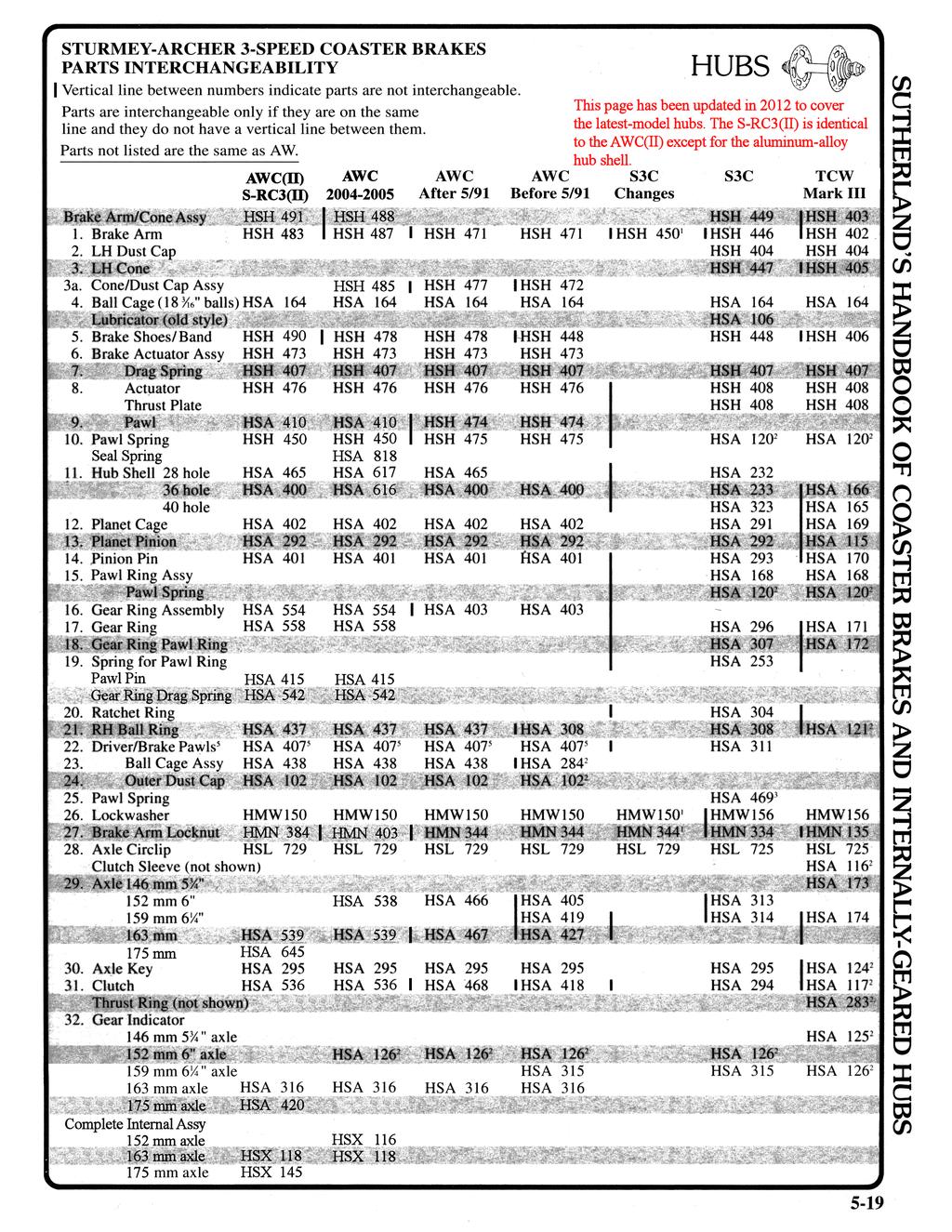
1 STURMEY ARCHER 3 SPEED COASTER BRAKE A WC (after 5/91) ~ ~~@~~ S3C 'The lockwasher, brake arm nut and brake arm as a unit may be interchanged. 2Same as AW. 3HSA 469 replaces HSA 302 (see Subassembly text). 4If thrust ring has same size opening at both ends, a thrust washer must be installed. This occurs only on older models. 5Hub shells marked 88-8 (August 1988) or earlier have 2 pawl drivers. Replace 2 pawl driver assembly and clutch together. 5 18
2
3 STURMEY-ARCHER S3C DISASSEMBL Y AND ASSEMBLY o DISASSEMBLY I Loosen but do not remove cone locknut and brake arm nut. 0DISASSEMBLY I brake arm nut Adjust bearing and lock brake arm nut in place with locknut. I ASSEMBLY. The right-hand ball ring may have a double start thread. If the ball ring is replaced in the opposite position, the wheel may need retruing. To facilitate proper reassembly, mark the ball ring at the point nearest the lubricator. drift punch Tighten right-hand ball ring with a hammer and drift punch. I ASSEMBLY. Place a drift punch as shown and loosen the ball ring by rapping the punch firmly with a hammer. Do not try to unscrew it completely. o DISASSEMBLY I Remove cone locknut, lock washer, and brake arm nut. The brake arm, dust cap and left-hand cone may come off separately or as a unit. They can easily be pressed apart if required. Remove ball retainer. Next Page cone locknut, lock washe~ brake nut~ Install brake arm nut, lock washer and cone locknut finger tight.. brake arm~ ~ dmt ca~ Replace ball retainc< flat,ide up. If retainer will not seat properly, check left-hand a thrust plate and pawl ring installation cone (step 3). Install cone, dust cover and ball / " brake arm (brand name facing out). retainer The inward face of the cone has three slots; the two wide slots engage the brake band tabs, the narrow slot engages the brake actuating spring. It may be necessary to rotate the spring before installing the cone. I ASSEMBLY. 5-20

4 STURMEY-ARCHER S3C DISASSEMBL Y AND ASSEMBLY o DISASSEMBLY I Unscrew right-hand ball ring from the bottom of hub shell and remove cartridge. hub right-hand ball. * HUBS Preceding Page Without inverting cartridge, slip it into the l;l.ub shell and thread ball ring finger tight. If the mark made during disassembly is not beside the lubricator, remove and restart cartridge. Do not tip or invert hub until left-hand locknut has been installed in the next step. I ASSEMBLY. 0DISASSEMBLY I Remove brake band, thrust plate and planet cage pawl ring. If required brake actuating spring can be pried off thrust plate with a thin-bladed screwdriver. brake pinion pin end. Turn assembly over. Install brake actuating spring on thrust plate if it was removed: Viewed as shown hooked end of spring must be clockwise from gap. Incorrect installation will cause excessive drag and wear. Rotate pinion pins so the flats face outwards. Insert tabs of planet cage pawl ring into slots on thrust plate. Screw the pawl ring and thrust plate onto the planet cage until pawl ring seats on the planet cage. Install brake band, tabs up. G)DISASSEMBLY I Hold down ball ring while removing right-hand locknut, lock washer, cone clutch spring, spring cap and driver! (rotate driver to disengage driver pawls). If driver catches on ball ring, remove both parts together; be careful not to damage pawl springs when separating them. Lift off ball ring, ratchet ring and gear ring pawl ring. ratchet rin beveled edge--!~.~/r:j gear ring tab keyway. Install ball ring. Push pawls in and rotate ring until seated over pawls. Install driver.! Push pawls in and turn driver clockwise until it seats in ball ring. Install spring and spring cap.! Install cone, lock washer and locknut. Adjust bearing. If bearing runs rough, check spring cap.! Replace gear ring pawl ring beveled edge down. Pawls must point clockwise when viewed from above. Top face of ring should be flush with top of gear ring tabs. Install ratchet ring. Ratchet ring keys must be engaged in keyways of the gear ring tabs. If the keys are positioned beside the gear ring tabs, low gear may not engage properly. ASSEMBLY!Old model spring caps are too l ~rge to fitthrough the driver. On these hubs, the spring and cap are removed after and installed before the driver. Otherwise the spring cap will be compressed between the cone and the bearing with damage to both. Upon installation the driver must be held in place against the spring until the cone is installed. 5-21
5 * HUBS 0DISASSEMBLY I Remove gear ring, clutch and axle key. Push out pinion pins and remove pinions. Pry off planet cage circlip and remove planet cage. ge.,'ingd clutch Preceding Page STURMEY-ARCHER S3C DISASSEMBLY AND ASSEMBLY (cont.) Slide planet cage over left end of axle past circlip groove and replace circlip. Replace pinions and pinion pins. Orient the pins as shown. Center axle key in the bottom of the axle slot with threaded hole parallel to axle. Slide clutch over axle key. Clutch should contact face of planet cage and engage pinion pins. Install gear ring. circlip-o IDISASSEMBLY I Ball Ring, Driver and Pawl Rings Bearings. Remove dust cover with a thin-bladed screwdriver. Work slowly around cover to avoid deforming it. Lift out balls or ball retainer. Pawls. Pawl springs can be removed with the pawls in place, although some deformation usually results. Ease the hooked end of the spring over the side or long end of pawl to the other side. Spread the ends of spring < SUBASSEMBLIES dust cap ball retainer balls Ball Ring, Driver and Pawl Rings Bearings. Install balls or ball retainer. Orient retainer as shown. Start dust cover straight by hand and tap home with a soft hammer. ballring~ Pawls. If only pawl springs have been driver removed, springs may be fitted with pawl Va pawls in place. Use only new style pawl springs. Early types tend to break. Holding spring by hooked end, hook Driver Pawl Springs straight end around pawl pin beside current obsolete styles pawl. Ease hooked end over the side style (breakage prone) or long end of pawl. Straight end must come to bear on piece body and hooked end on inside surface of pawl slightly behind driving edge. and slide out. bright finish dull bright HSA 469 finish finish If pawls were removed, install pawl, If pawls are to be removed, pawl spring and pin together. Make sure Q springs are best removed at I pawls are oriented as shown. Straight. h. R' d I ' P anet cage gear ring t at time. IVete paw pms pawl ring pawl ring solid pins must be lightly riveted over. can be removed only by File end of pin flush. Hollow pins are drilling. Hollow pawl pins can ~ ~ driven in with a soft hammer. Grooved be driven out with the correct o~ ~_. /6' ~river pawl pins are installed groove first size drift punch. Some drivers. and retained by a circlip around the use removable pawl pins held driver. in place by a circlip. Do not I pawl I mix up pawl sprin'es. --=:::::::, I ASSEMBLY I s prlngs ~ HSA 253 HSA
6 STURMEY-ARCHER S3C DISASSEMBLY AND ASSEMBLY (cont.) CLEANING Clean all parts, including outside of hub shell and axle bore, in a suitable solvent. Be very careful not to introduce dirt or grit after cleaning. POINTS TO CHECK Part numbers followed by * refer to A W parts chart, others to S3C or TCW-III parts chart. I. Clutch (26) and gear ring dogs (14) for rounded or chipped driving edges (rounqing to a radius of even \164" (0.4 mm) at the corners can cause hub to slip out of gear) 2. Pawls (12*, 19,21*), ball ring (18), lefthand ball cup (5) and ratchet ring (17) for rounded or chipped driving edges 3. Sun pinion (24), planet pinions (II) and gear ring (14) for worn or chipped teeth 4. Bearing surfaces of left-hand cone (3), left-hand ball cup (5), ball ring (18), driver (19), right-hand cone (5*) and pinion pins (12) for wear and pitting 5. Axle key (25) and indicator for stripped threads 6. Clutch spring (32*) and brake actuating spring (7) for size and tension 7. Dustcaps and ball retainers for straightness 8. All threaded parts for worn or damaged threads 9. Axle (24) for straightness 10. Planet cage (13) and thrust plate (8) threads for wear or roughness II. Thrust plate (8) and brake band (6) serrations for wear 12. Brake band (6) and hub shell (5) for wear or glazing LUBRICATION Lubricate ball retainers by filling the spaces between balls with grease. Lubricate hub shell and brake band liberally with a hightemperature grease. Be careful not to grease pawls. Lightly oil other internal parts with a good cycle oil. (WD-40 is too light for lasting lubrication, 3-in-1 Oil gums up with age.) Add about two teaspoons (8 ml) of oil when assembled. 5-23
7 ~HUBS ~ STURMEY-ARCHER AWC DISASSEMBLY AND ASSEMBLY C!:)DISASSEMBLY 1 locknut ~----t.!~ lockwasher -----{ brake arm nut ,.~.l brake arm ---) dustcap and cone assembly --~~~~~ Remove left-hand locknut, lockwasher, brake arm nut and brake arm. Remove cone and dustcap assembly and ball retainer. For hubs manufactured 5/91 and after, cone and dustcap assembly are one piece. Tum upside down so the brake shoes fall out. <!) DISASSEMBLY I The right-hand ball ring has a double start thread. If the ball ring is replaced in the opposite position, the wheel may need retruing. To facilitate proper reassembly, mark the ball ring and hub shell. Place a drift punch as shown and loosen the ball ring by rapping the punch firmly with a hammer. Next Page brake shoes -~l~il~ ball retainer --(o~~ Iid~ Space the brake shoe segments evenly between brake actuator assembly and hub shell. Slotted edge of shoe segments should be facing up. Place ball cage assembly (ballside down) inside the hub. Note the slot in the brake cone and align it with the drag spring on the brake actuator. Gently place dustcap and cone assembly onto the hub, turning gently so that shoe segments will line up into proper position, allowing a tight fit without forcing it. Attach brake arm (label face up) into slot on dustcap. Screw on brake arm nut, lock washer and locknut. - drift punch.:--. ""',.----\-4\-- ball ring 1 ASSEMBLY. Tighten right-hand ball ring with a hammer arid drift punch. 1 ASSEMBLY 5-24
8 STURMEY-ARCHER AWC DISASSEMBLY AND ASSEMBLY (cont.) <!)DISASSEMBLY I Unscrew right hand ball ring and remove the entire internal gear assembly. Remove the brake actuator assembly by turning it counterclockwise. HUBS~ ~ Preceding Page drag spring --'7~~~ planet cage ;MI--.lor77&. gear ring assembly ---t',~,,------,9-- Turn the cartridge over. Screw brake actuator assembly clockwise onto planet cage. Slide axle assembly into the hub shell, then screw ballring to hub shell. G) DISASSEMBLY I Turn cartridge over. Remove right hand locknut, spacers (if any), lockwasher, cone, clutch spring and cap from axle. Remove driver assembly, ball cage/dust cap assembly as one unit from axle. Depress the pawls in the driver. assembly to release the driver assembly from ball cage assembly and ball ring. ~IOCknut ~ cone spacer lockwasher cap \.J'"---- clutch spring "'-"l---driver assembly ball cage assembly I ASSEMBLY Next Page ball ring gear ring assembly ---V planet cage ---~vu:::~r- Place ball ring on gear ring assembly. Seat ball cage assembly (ball side down) into ball ring. Using a screwdriver, depress pawls of driver assembly so the driver assembly seats in the ball ring. Place tht< dutch spring and cap, over axle as shown. Screw on cone, lockwasher, spacer, if any, and locknut. I ASSEMBLY. 5-25
9 G) DISASSEMBLY I Remove the gear ring assembly. Remove the clutch and axle key from axle. Remove pinion pins to release planet pinions from the planet cage. Using snap ring-pliers, remove planet cage circlip and remove planet cage. planet cage ---\ STURMEY-ARCHER AWC DISASSEMBLY AND ASSEMBLY (cont.) Preceding Page gear ring assembly (1---- clutch r-q- pinion pin ~ planet pinion axle circlip ---~~ Slide planet cage assembly over left end of axle (side without axle key slot) over circlip groove and install new circlip. Clamp left end of axle in a vise (axle key slot up). Replace pinions and pinion pins. Orient the pins as shown. Center axle key into bottom of axle slot with threaded hole visible when looking down into slot. Install clutch over end of axle. Install gear ring assembly so that planet pinions mesh with the gear ring. I ASSEMBLY. 5-26
10 STURMEY-ARCHER AWC DISASSEMBLY AND ASSEMBLY (cont.) HUBS~ ~ CLEANING Clean all parts, including outside of hub shell and axle bore, in a suitable solvent. Be very careful not to introduce dirt or grit after cleaning. POINTS TO CHECK 1. All threaded parts for worn or damaged threads. If hub shell is marked 88-8 or earlier, both clutch and driver assembly must be replaced at the same time. 2. Pinions (13), axle (29) and gear ring assembly (16) for worn gear teeth. 3. Axle (29) for straightness. 4. Gear ring assembly (16) and driver assembly (22) for wear and chipping. Drag spring on gear ring assembly assembly should move freely. Clutch (31) should slide easily into driver assembly. Manufacturer recommends replacing either assembly entirely with new factory-fitted assembly if any part of subassembly is not suitable. 5. Hub shell (11) for condition of LH ball track, ratchet and braking surface. 6. Ball cage assembly (4) should have 24 bearings if assembly is separate from dustcap, 14 bearings if ball cage and dustcap seal are integral. 7. Pawl (9) and pawl spring (10) in brake actuator assembly (6). Drag spring (7) should easily turn clockwise and have great resistance when rotated counterclockwise. 8. Brake arm (1). Replace if damaged. 9. Brake band or shoe segments (5) for wearing and glazing. LUBRICATION Lubricate ball retainers by filling the spaces between balls with grease. Lubricate hub shell and brake shoes liberally with a high-temperature grease. Be careful not to grease the pawls. Lightly oil other internal parts with a good cycle oil, (WD-40 is too light for lasting lubrication, 3-in-l Oil gums up with age.) Add about two teaspoons (8 ml) of oil when assembled. 5-27
Maintenance Information
 16572679 Edition 2 May 2014 Air Drill QP Series Maintenance Information Save These Instructions Product Safety Information WARNING Failure to observe the following warnings, and to avoid these potentially
Technical Infor m ation and Parts List. Sprinter Coaster Five Speed Hub Brake
 Technical Infor m ation and Parts List Sprinter Coaster Five Speed Hub Brake Part 1 GENERAL INFORMATION 1.1 SCOPE OF THIS LEAFLET Congratulations upon your purchase of a Sturmey-Archer SPRINTER COASTER
Technical Infor m ation and Parts List. Hub Brakes (90mm) AB/C - BF/C
 AB/C - BF/C") Technical Infor m ation and Parts List Hub Brakes (90mm) AB/C - BF/C Technical Information- 90mm Hub Brakes Part 1 GENERAL INFORMATION The information contained in this manual relates specifically to the
Technical Infor m ation and Parts List Hub Brakes (90mm) AB/C - BF/C Technical Information- 90mm Hub Brakes Part 1 GENERAL INFORMATION The information contained in this manual relates specifically to the
Maintenance Information
 80234313 Edition 1 June 2006 Air Grinder, Die Grinder, Sander and Belt Sander Series G1 (Angle) Maintenance Information Save These Instructions WARNING Always wear eye protection when operating or performing
Maintenance Information
 80234313 Edition 2 May 2014 Air Grinder, Die Grinder, Sander and Belt Sander Series G1 (Angle) Maintenance Information Save These Instructions Product Safety Information WARNING Failure to observe the
REPAIR MANUAL URW SERIES. URW-6, 8, 9, 10 & 12 Series Repair Manual
 REPAIR MANUAL URW SERIES URW-6, 8, 9, 10 & 12 Series Repair Manual Contents Page 1. Tools Needed for Repair 1 2. Disassembly and Reassembly of the Cam Casing 2-4 3. Disassembly and Reassembly of the Gear
Maintenance Information
 04581245 Edition 2 May 2014 Air Grinder, Die Grinder and Sander Series G2 (Angle) Maintenance Information Save These Instructions Product Safety Information WARNING Failure to observe the following warnings,
Maintenance Information
 16575219 Edition 4 October 2013 Air Screwdrivers QP1P, QP1S and QP1T Series Maintenance Information Save These Instructions Product Safety Information WARNING Failure to observe the following warnings,
Maintenance Information
 45528270 Edition 1 June 2007 Barring Motor T480 Series Maintenance Information Save These Instructions WARNING Always wear eye protection when operating or performing maintenance on this Barring Motor.
MAINTENANCE ROAD 2013 WHEELS TECHNICAL MANUAL
 2013 WHEELS TECHNICAL MANUAL ROAD CYCLOCROSS PISTA GROUPSET TYPE OPERATION REVISION DESCRIPTION ROAD GROUPSETS CONE / CUP MOVEMENT 002 1/2011 SERVICING FRONT HUB ASSEMBLY PRODUCTS ON WHICH THE PROCEDURE
Technical Infor m ation and Parts List. Sprinter and Sprinter Elite Five Speed Hubs
 Technical Infor m ation and Parts List Sprinter and Sprinter Elite Five Speed Hubs Part 1 GENERAL INFORMATION 1.1 SCOPE OF THIS LEAFLET Congratulations upon your purchase of a Sturmey-Archer SPRINTER 5-SPEED
Maintenance Information
 16584062 Edition 3 December 2013 High Torque Reversible Angle Screwdrivers and Angle Wrenches QA1L High Torque Series Maintenance Information Save These Instructions Product Safety Information WARNING
Information of QSRC Hubs Assembling
 Information of QSRC Hubs Assembling Top Right Front Left Bottom Transmission General Arrangement Cog on Drive Shaft Cog on Hub Shell Cog Drive Shaft Chain to Drive Shaft Hub Chain to Crankset System Moving
Maintenance Information
 Form 04584058 Edition 1 November 2004 Air Impactool 2141P and 2141PSP Maintenance Information Save These Instructions Disassembly General Instructions 1. Do not disassemble the tool any further than necessary
Elite Alloy Hub Brakes
 Technical Infor m ation and Parts List Elite Alloy Hub Brakes V T - ST - AT 3 Technical Information- Elite Alloy Hubs Part 1 GENERAL INFORMATION Fig. 1 - Gear Adjustment Fig. 2 HMN 132 The information
Maintenance Information
 16575243 Edition 2 October 2013 Air Screwdrivers 1R Series Maintenance Information Save These Instructions Product Safety Information WARNING Failure to observe the following warnings, and to avoid these
Maintenance Information
 16573347 Edition 2 February 2014 Air Grinder Series 88H Maintenance Information Save These Instructions Product Safety Information WARNING Failure to observe the following warnings, and to avoid these
UOW Series Repair Manual UOW-11 & UOW-T60 Series
 UOW Series Repair Manual UOW-11 & UOW-T60 Series 100000 SE Pine St., Portland, OR 97216 800-852-1368 503-254-6600 www.aimco-global.com Contents Page 1. Tools Needed for Repair 2 2. Disassembly and Reassembly
Maintenance Instructions
 General Note These instructions contain information common to more than one model of Bevel Gear Drive. To simplify reading, similar models have been grouped as follows: GROUP 1 Models 11, 0, 1,, (illustrated),,
FOR FUTURE REFERENCE SERIES 93HPS
 Hypro Series 93HPS Hydraulically Driven Wetseal Multistage Pumps Repair Manual KEEP FOR FUTURE REFERENCE Form L-1578R Rev. A SERIES 93HPS Hydraulically Driven Stainless Steel Multistage Centrifugal Pumps
Transmission Overhaul Procedures-Bench Service
 How to Assemble the Lower Reverse Idler Gear Assembly Special Instructions In 1996 Eaton changed the reverse idler system design. In the nut design, the reverse idler bearing was lubricated through a hole
Sub Section Title Page No.
 Sub Section Title Page No. 1 Introduction 3 2 Routine Maintenance 3 3 Disassembly 4 3.1 Disassembly of Double Crank Design 4 3.2 Disassembly of Scotch Yoke Design 5 3.3 Disassembly of Actuator Cylinder
3.2 DRIVE TORQUE HUB. Roll, Leak and Brake Testing SECTION 3 - CHASSIS & TURNTABLE. 3-2 JLG Lift
 3.2 DRIVE TORQUE HUB Roll, Leak and Brake Testing 10 LUG PATTERN Torque-Hub units should always be roll and leak tested before disassembly and after assembly to make sure that the unit's gears, bearings
Amarillo PUMP DRIVES (250 HP THROUGH 350 HP) INSTRUCTIONS FOR REPAIRING MODELS 250, 300, and 350
 INSTRUCTIONS FOR REPAIRING MODELS 250, 300, and 350") Amarillo PUMP DRIVES (250 HP THROUGH 350 HP) INSTRUCTIONS FOR REPAIRING MODELS 250, 300, and 350 Amarillo Right Angle Pump Drives, if properly installed and maintained, should provide years of service
Amarillo PUMP DRIVES (250 HP THROUGH 350 HP) INSTRUCTIONS FOR REPAIRING MODELS 250, 300, and 350 Amarillo Right Angle Pump Drives, if properly installed and maintained, should provide years of service
Maintenance Information
 16575128 Edition 2 May 2014 Air Grinder, Sander or Polisher 77A Series Maintenance Information Save These Instructions Product Safety Information Failure to observe the following warnings, and to avoid
UAN Series Pneumatic Nutrunner Repair Manual
 UAN Series Pneumatic Nutrunner Repair Manual PO Box 16460, Portland, OR 97292-0460 503-254-6600 Fax 503-255-2615 www.aimco-global.com Contents Page 1. Tools Needed for Repair of UAN Series Pneumatic Nutrunner
DRIVE AXLE Volvo 960 DESCRIPTION & OPERATION AXLE IDENTIFICATION DRIVE AXLES Volvo Differentials & Axle Shafts
 DRIVE AXLE 1994 Volvo 960 1994 DRIVE AXLES Volvo Differentials & Axle Shafts 960 DESCRIPTION & OPERATION All 960 station wagon models use type 1041 rear axle assembly. All 960 4-door models use type 1045
Fichtel and Sachs Old Torpedo Duomatic Re-assembly
 Fichtel and Sachs Old Torpedo Duomatic Re-assembly Inspection and assessment Refer to the final photograph in the dismantling instructions to see how all the parts should look cleaned up. This hub came
1989 Jeep Cherokee. STEERING COLUMN' '1989 STEERING Jeep Steering Columns STEERING COLUMN STEERING Jeep Steering Columns
 STEERING COLUMN 1989 STEERING Jeep Steering Columns DESCRIPTION All models use collapsible steering columns. All columns have integral ignition switch and locking device. Optional tilt wheel is available
12 L * OH**
 Parts Manual Ersatzteil--Liste 12L27.. series 0.9 hp ERGO Short Coupled Low Profile Grinders & Sanders 45--8175 TOOL CLASSIFICATION 12 = ERGO Grinder/Sander 12 L 2 7 12 27 08* OH** -- TYPICAL MODEL THROTTLE
This file is available for free download at
 This file is available for free download at http://www.iluvmyrx7.com This file is fully text-searchable select Edit and Find and type in what you re looking for. This file is intended more for online viewing
Steering Column. Disassembly. 1. Remove instrument panel cover and reinforcement from vehicle as described in this section.
 Page 1 of 14 Section 11-04A: Steering Column, Ranger 1997 Aerostar/Ranger Workshop Manual DISASSEMBLY AND ASSEMBLY Procedure revision date: 05/17/2000 Steering Column Disassembly 1. Remove instrument panel
Discount-Equipment.com
 REQUIRED TOOLS LS Series Remix Shaft Installation Instructions /8", /6", /2" Allen Wrenches Snap Ring Pliers (Light Duty) /" Combination Wrench Loctite #22 Blue /" Socket w/ /8" Ratchet Electric Drill
Transaxle. 1. Mount the transaxle to Bench Mounted Holding Fixture T57L-500-B.
 «1997 Aspire Table of Contents» «Group 07: TRANSAXLE» «Section 07-01: Transaxle, Automatic» «DISASSEMBLY» Transaxle CAUTION: To prevent dirt from entering the transaxle, it should be disassembled and kept
Maintenance Information
 16573370 Edition 2 February 2014 Air Grinder 99V Series Maintenance Information Save These Instructions Product Safety Information WARNING Failure to observe the following warnings, and to avoid these
1984 Dodge W250 PICKUP
 1984 Dodge W250 PICKUP Submodel: Engine Type: V8 Liters: 5.2 Fuel Delivery: CARB Fuel: GAS Dana 44 MODELS THROUGH 1984 2. Raise and safely support the vehicle, then remove the wheel hub and bearings as
Discount-Equipment.com
 LS40D, LS40TD, LS50TD, LS60TD LS-Series Remix Shaft Coupler Retrofit Kit Installation Instructions The following instructions are intended to assist the user in the installtion of the LS-Series Remix Shaft
Genesis Double Adjustable Shock Assembly and Repair
 Genesis Double Adjustable Shock Assembly and Repair General Operating Description The Genesis Adjustable Shock is adjusted by moving one or both of two bypassing sliding valves. These valves slide longitudinally
LIFT TRUCK SERIES: G35S-2 G40S-2 G45S-2 G40SC-2 G45SC-2 G50SC-2. November 15, 2000 CODE 3150 LT3150-L0 SUBJECT: NEW DRIVE AXLE
 LIFT TRUCK SERIES: G35S-2 G40S-2 G45S-2 G40SC-2 G45SC-2 G50SC-2 November 15, 2000 CODE 3150 LT3150-L0 SUBJECT: NEW DRIVE AXLE A new drive axle has been introduced in the above model lift trucks. The purpose
DISASSEMBLY AND ASSEMBLY
 205-03-1 Front Drive Axle/Differential Ford 8.8-Inch Ring Gear 205-03-1 DISASSEMBLY AND ASSEMBLY Axle Front Drive Special Tool(s) 2-Jaw Puller 205-D072 (D97L-4221-A) Special Tool(s) Carrier Bearing Replacer
Maintenance Information
 Form 16573321 Edition 1 July 2004 Air Grinder Series 61H Maintenance Information Save These Instructions Always wear eye protection when operating or performing maintenance on this tool. Always turn off
OPERATING INSTRUCTIONS AND SERVICE MANUAL
 OPERATING INSTRUCTIONS AND SERVICE MANUAL 55NAL--270-4 55NL--724-4 55RNL-2-LS-4- COMPLETE TOOL MODEL NO. CODE NO. 55NAL--270-4 20270 55NL--724-4 220724 READ SAFETY RECOMMENDATIONS 55RNL-2-LS-4-24089 BEFORE
Section 13. Tail Rotor Drive. RotorWay International A600 TALON Construction Manual. Section 13. Page A
 RotorWay International Page A Tail Rotor Drive Procedures covered in this section: Install driveshafts and gearboxes; install drive belt and tensioner; fabricate and install tail rotor pitch actuator arms;
BRAKE SYSTEM Nissan 240SX DESCRIPTION BRAKE BLEEDING * PLEASE READ FIRST * BLEEDING PROCEDURES ADJUSTMENTS BRAKE PEDAL HEIGHT SPECS TABLE
 BRAKE SYSTEM 1990 Nissan 240SX 1990 BRAKE SYSTEMS Nissan Disc & Drum Axxess, Maxima, Pathfinder, Pickup, Pulsar NX, Sentra, Stanza, 240SX, 300ZX DESCRIPTION All brake systems are hydraulically operated
A/C COMPRESSOR SERVICING Article Text 1991 Saab 9000 For Copyright 1997 Mitchell International Friday, October 15, :22PM
 Article Text ARTICLE BEGINNING 1991 GENERAL SERVICING Compressor Service * PLEASE READ THIS FIRST * CAUTION: When discharging air conditioning system, use only approved refrigerant recovery/recycling equipment.
Torqueflite Manual/Automatic Valve Body
 TCI 122400 Torqueflite Manual/Automatic Valve Body This valve body can be installed in a few hours by carefully following directions. Read all instructions first to familiarize yourself with the parts
Mandatory X Information Recommended Change. Series/Parts Affected: LS40D, LS40TD, LS50TD and LS60TD Concrete Pumps
 Service Bulletin No. CP20060428 Subject: Remix Shaft Coupler Retrofit Kit Model: LS40D, LS40TD, LS50TD & LS60TD Product Group: Concrete Pump Date: April 28, 2006 SERVICE BULLETIN Group: CP Mandatory X
DRIVE AXLE Nissan 240SX DESCRIPTION & OPERATION AXLE RATIO & IDENTIFICATION AXLE SHAFT & BEARING R & I DRIVE SHAFT R & I
 DRIVE AXLE 1990 Nissan 240SX 1990 DRIVE AXLES Rear Axle - R200 240SX, 300ZX DESCRIPTION & OPERATION The axle assembly is a hypoid type gear with integral carrier housing. The pinion bearing preload adjustment
TECHNICAL BULLETIN. TP Issued Servicing Rockwell s TB Series Trailer Axles with Unitized Hub Assemblies
 TECHNICAL BULLETIN TP-96175 Issued 12-96 Servicing Rockwell s TB Series Trailer Axles with Unitized Hub Assemblies TB Series Trailer Axles Introduction Rockwell s TB series trailer axle features a permanently
Service Manual. Example Part Number. Motor Supplier. Motor Number. Model. Bail Boss. Ratio. Shaft
 Service Manual 50 Series Digger models Example Part Number 50 05 f 54 Model Ratio Shaft Bail Boss Motor Supplier Motor Number This service manual is effective: S/N: 58670 to current date: 9-003 to CURRENT
Transmission Overhaul Procedures-Bench Service
 How to Install the Auxiliary Countershaft Assembly Special Instructions To make auxiliary section assembly easier, you can make an auxiliary section fixture out of a 2" x 12" piece of wood. 3' 1' 3" 4.56"
Maintenance Information
 16573321 Edition 3 February 2014 Air Grinder Series 61H Maintenance Information Save These Instructions Product Safety Information WARNING Failure to observe the following warnings, and to avoid these
2001 Dodge RAM 3500 PICKUP
 1 of 76 9/14/2012 7:02 PM 2001 Dodge RAM 3500 PICKUP Submodel: Engine Type: L6 Liters: 5.9 Fuel Delivery: FI Fuel: DIESEL Subarticles MANUAL- NV3500 - DISASSEMBLY MANUAL- NV3500 - DISASSEMBLY MANUAL -
CLUTCH CONTENTS SERVICE DIAGNOSIS. (a) Worn or damaged disc assembly. (b) Grease or oil on disc facings. (c) Improperly adjusted cover assembly.
 Worn or damaged disc assembly. (b) Grease or oil on disc facings. (c) Improperly adjusted cover assembly.") CLUTCH CONTENTS -GROUP 6 Page CLUTCH HOUSING ALIGNMENT... 6 CLUTCH PEDAL FREE PLAY 1 CLUTCH RELEASE BEARING 5 CLUTCH RELEASE FORK... 5 CLUTCH SERVICING 2 PILOT BUSHING CRANKSHAFT TO TRANSMISSION DRIVE
CLUTCH CONTENTS -GROUP 6 Page CLUTCH HOUSING ALIGNMENT... 6 CLUTCH PEDAL FREE PLAY 1 CLUTCH RELEASE BEARING 5 CLUTCH RELEASE FORK... 5 CLUTCH SERVICING 2 PILOT BUSHING CRANKSHAFT TO TRANSMISSION DRIVE
1999 F-150/250 Workshop Manual
 Page 1 of 30 SECTION 205-03: Front Drive Axle/Differential Ford 8.8-Inch Ring Gear 1999 F-150/250 Workshop Manual DISASSEMBLY AND ASSEMBLY Procedure revision date: 01/08/2003 Axle Front Drive Special Tool(s)
STERNDRIVE UNIT 3 B GEAR HOUSINGS MR/ALPHA ONE/ALPHA ONE SS
 STERNDRIVE UNIT 3 B 23146 GEAR HOUSINGS MR/ALPHA ONE/ALPHA ONE SS Table of Contents Page Identification........................... 3B-1 Specifications.......................... 3B-1 Torque Specifications................
MODELS 3100,3130,3160, 1300, 1330,1360 EXHAUST SYSTEM
 MODELS 3100,3130,3160, 1300, 1330,1360 EXHAUST SYSTEM WALBRO CARBURETOR "WA" SERIES MUFFLER REMOVAL CARBURETOR REMOVAL The muffler assembly should beremoved periodically to inspect for excessive carbon
Brake System H TX, H2.0TXS [B475]; H TX [B466] Safety Precautions Maintenance and Repair
![Brake System H TX, H2.0TXS [B475]; H TX [B466] Safety Precautions Maintenance and Repair](/thumbs/86/93834005.jpg "Brake System H TX, H2.0TXS [B475]; H TX [B466] Safety Precautions Maintenance and Repair") HMM180001 Brake System H1.5-1.8TX, H2.0TXS [B475]; H2.5-3.5TX [B466] Safety Precautions Maintenance and Repair When lifting parts or assemblies, make sure all slings, chains, or cables are correctly fastened,
HMM180001 Brake System H1.5-1.8TX, H2.0TXS [B475]; H2.5-3.5TX [B466] Safety Precautions Maintenance and Repair When lifting parts or assemblies, make sure all slings, chains, or cables are correctly fastened,
AMARILLO PUMP DRIVES MODEL 1 OOOA, 1200, 1500, 1800
 AMARILLO PUMP DRIVES MODEL 1 OOOA, 1200, 1500, 1800 INSTRUCTIONS FOR REPAIRING MARCH 1, 1993 AMARILLO GEAR COMPANY Post Office Box 1789, Amarillo, Texas 79105 806 / 622-1273 FAX 806 / 622-3258 INSTRUCTIONS
Return to Instruction Sheet index TCI Torqueflite Trans-Scat Kit
 Page 1 of 11 Return to Instruction Sheet index TCI 220000 Torqueflite Trans-Scat Kit This kit can be installed in a few hours by carefully following directions. Read all instructions first to familiarize
INSTALLATION INSTRUCTIONS
 INSTALLATION INSTRUCTIONS WARNING: NEVER EXCEED YOUR VEHICLE MANUFACTURER'S RECOMMENDED TOWING CAPACITY PIN-STYLE TRUNNION BAR WEIGHT DISTRIBUTION KIT MAINTENANCE Keep the socket-mounted ends of the spring
Maintenance Information
 16606022 Edition 3 May 2014 Air Drill 728 Series Maintenance Information Save These Instructions Product Safety Information WARNING Failure to observe the following warnings, and to avoid these potentially
INSTALLATION GUIDE. Kawasaki KLR Manual Revision:
 REKLUSE MOTOR SPORTS The z-start Pro Clutch INSTALLATION GUIDE Kawasaki KLR650 191-640 Manual Revision: 030308 2007 Rekluse Motor Sports Rekluse Motor Sports, Inc. 110 E. 43rd Street Boise, Idaho 83714
MAIN PRICE LIST. - B 487 Perforated Strip 2 1/2" B 488 Perforated Strip 3 1/2" B 482 Perforated Strip 4 1/2" 9 1.
 PERFORATED STRIPS LENGTH HOLES GBP 1 Perforated Strip 12 1/2" 25 1.63 1 a Perforated Strip 9 1/2" 19 1.51 1 b Perforated Strip 7 1/2" 15 1.39 2 Perforated Strip 5 1/2" 11 0.90 2 a Perforated Strip 4 1/2"
INSTRUCTIONS FOR OVERHAUL OF RAMEY RE SERIES WINCH
 INSTRUCTIONS FOR OVERHAUL OF RAMEY RE 12000 SERIES WINCH DISASSEMBLY 1. Drain oil from gear housing by removing plug # from bottom of gear housing. Remove relief fitting # and reducer # from top of gear
TRANSMISSION 6.7 GENERAL HOME. See Figure The transmission is a five-speed constantmesh type housed in an extension of the crankcase.
 TRANSMISSION 6.7 GENERAL See Figure 6-45. The transmission is a five-speed constantmesh type housed in an extension of the crankcase. Mainshaft Neutral Mainshaft st Gear b06x6x Countershaft 4 Out 5 Countershaft
Torqueflite Trans-Scat Kit
 TCI 220000 Torqueflite Trans-Scat Kit This kit can be installed in a few hours by carefully following directions. Read all instructions first to familiarize yourself with the parts and procedures. Work
1 Green Pressure Regulator Spring Automatic transmissions operate at temperatures between 150ºF and
 Installation Instructions for 603107 Valve Body Kit C-4 1970 & Later Tools Required Speed Handle or Ratchet 3/8 Drive 1/2 Socket 3/8 Drive 7/16 Socket 3/8 Drive 5/16 Socket 3/8 Drive Small Screwdriver
Service Manual Air Tech Second Stage
 Service Manual Air Tech Second Stage Copyright 2002, Cressi-sub Revised 3/2002 2 Air Tech Second Stage Service Manual Contents BEFORE STARTING... 3 DISASSEMBLY... 3 PARTS CLEANING AND LUBRICATION... 9
MailStar Maintenance and Adjustment March 2002
 MailStar Maintenance and Adjustment March 2002 The MailStar bicycle incorporates many new features to ease maintenance and improve handling and performance. The majority of components are similar to those
2003 Dodge Pickup R DRIVE AXLES' 'Axle Shafts - Front - Ram Pickup WD DRIVE AXLES
 2002-04 DRIVE AXLES Axle Shafts - Front - Ram Pickup 1500 4WD DESCRIPTION Vehicles equipped with 4WD and C205F front axle assembly use equal length axle shaft system to deliver power from front differential
FRONT AXLE SECTION FAX CONTENTS DRIVELINE/AXLE FAX-1 SERVICE INFORMATION... 2
 DRIVELINE/AXLE SECTION FAX A FRONT AXLE B C FAX CONTENTS E SERVICE INFORMATION... 2 PRECAUTIONS... 2 Caution...2 PREPARATION... 3 Special Service Tool...3 Commercial Service Tool...3 NOISE, VIBRATION AND
Valtek Auxiliary Handwheels and Limit Stops
 Valtek Auxiliary s and Limit Stops Table of Contents Page 1 General information 2 Installation 2 Side-mounted handwheels, size 25 and 50 (linear actuators) 3 Side-mounted handwheels, size 100 and 200 (linear
Actuator Maintenance Manual, E-Type size 8 to 150
 English Actuator Maintenance Manual, E-Type size 8 to 150 Precautions - Warning Always take care to follow this manual in order to correctly maintain the TruTorq actuators. Before removing the actuator,
This file is available for free download at
 This file is available for free download at http://www.iluvmyrx7.com This file is fully text-searchable select Edit and Find and type in what you re looking for. This file is intended more for online viewing
1. Remove the parking brake assembly. 2. Remove the 4 bolts holding the yoke flange and drum. Remove the yoke flange and drive.
 Disassembly NOTE: To replace the brake assembly, brake shoe and lining assemblies, or other operational components the complete parking brake assembly must be removed from the vehicle. 1. Remove the parking
SD Bendix Manual Slack Adjusters DESCRIPTION ADJUSTING MECHANISM OPERATION
 SD-05-1200 Bendix Manual Slack Adjusters WORM SHAFT (LOCK SCREW) FIGURE 1 - POSITIVE LOCK TYPE SLACK ADJUSTER DESCRIPTION In an s-cam type foundation brake, the final link between the pneumatic system
LS Series. Remix Shaft Installation Instructions REQUIRED TOOLS PARTS WORK SAFELY! PREPARATION/SAFETY PROCEDURES
 REQUIRED TOOLS LS Series Remix Shaft Installation Instructions /8", /6", /2" Allen Wrenches Snap Ring Pliers (Light Duty) /" Combination Wrench Loctite #22 Blue /" Socket w/ /8" Ratchet Electric Drill
MAINTENANCE WEIGHT RATINGS WARNINGS. warning: never exceed your vehicle manufacturer's recommended towing capacity
 Installation instructions warning: never exceed your vehicle manufacturer's recommended towing capacity Round Bar WEIGHT DISTRIBUTION kit MAINTENANCE Keep the socket-mounted ends of the spring bars and
LIMITED SLIP DIFFERENTIAL INSTALLATION
 Installation of the limited slip gear can be done with axle out of car or with car lifted to gain access from underneath. Refer to repair manual for proper lifting instructions if car is to be lifted.
DISASSEMBLY. Transmission. All vehicles
 307-01-1 Automatic Transmission 5R44E and 5R55E 307-01-1 DISASSEMBLY Transmission Special Tool(s) Holding Fixture, Transmission 307-262 (T93T-77002-AH) Special Tool(s) Remover, Servo 307-347 (T97T-7D021-A)
REPAIR PROCEDURES MANUAL
 REPAIR PROCEDURES MANUAL PVX Series Vane Pumps A Design Series Step-by-Step Guide to Troubleshooting and Repairing PVX Series Vane Pumps Introduction Thank you for choosing Continental Hydraulics PVX Vane
DelTech Controls L.L.C.
 DelTech Controls L.L.C. DelTorq Series 20 ACTUATORS TECHNICAL DATA SHEET T.D.S. NO. 20 105 / R1 ISSUE DATE : NOV 2004 INSTALLATION, OPERATION AND MAINTENANCE MANUAL Guarantee : ( Please read the entire
2002 F-Super Duty /Excursion Workshop Manual
 Page 1 of 25 SECTION 307-01: Automatic Transaxle/Transmission 2002 F-Super Duty 250-550/Excursion Workshop Manual ASSEMBLY Procedure revision date: 05/23/2001 Transmission Special Tool(s) Remover, O-Ring
1988 Chevrolet Pickup V SUSPENSION - FRONT (4WD)' 'Front Suspension - "V" Series 1988 SUSPENSION - FRONT (4WD) Front Suspension - "V" Series
' 'Front Suspension - V Series 1988 SUSPENSION - FRONT (4WD) Front Suspension - V Series") 1988 SUSPENSION - FRONT (4WD) Front Suspension - "V" Series DESCRIPTION NOTE: Vehicle serial numbers used in this article has been abbreviated for common reference to Chevrolet and GMC models. Chevrolet
1988 SUSPENSION - FRONT (4WD) Front Suspension - "V" Series DESCRIPTION NOTE: Vehicle serial numbers used in this article has been abbreviated for common reference to Chevrolet and GMC models. Chevrolet
Service Manual. #19 Gearmatic Winch
 Allis Chalmers Service Manual #19 Gearmatic Winch Service Manual THIS IS A MANUAL PRODUCED BY JENSALES INC. WITHOUT THE AUTHORIZATION OF ALLIS CHALMERS OR IT S SUCCESSORS. ALLIS CHALMERS AND IT S SUCCESSORS
TC20 Chain Driven Power Take-Off Overhaul Instructions
 TC20 Chain Driven Power Take-Off Overhaul Instructions Table of Contents Section Page Introduction 4 Ordering Repair Parts 4 General Information 5 Special Tools 6 Disassembly See Page 2 Reassembly See
INTEGRAL POWER STEERING GEAR FORD Applies to F-100 F-350 (4X2), F-150 F-250 (4X4) And Bronco
, F-150 F-250 (4X4) And Bronco") Rockcrawler Steering Shop Manual page1 The following is from the Ford 1978 Truck Shop Manual, Volume 1 Chassis. It is provided here as a courtesy to classic Ford owners who would like to perform their
Rockcrawler Steering Shop Manual page1 The following is from the Ford 1978 Truck Shop Manual, Volume 1 Chassis. It is provided here as a courtesy to classic Ford owners who would like to perform their
Steering Gear: Service and Repair POWER STEERING GEAR BOX
 2003 Kia Truck Sorento V6-3.5L Copyright 2013, ALLDATA 10.52 Page 1 Steering Gear: Service and Repair POWER STEERING GEAR BOX COMPONENTS REMOVAL 1. Drain the power steering fluid. 2. Disconnect the pressure
REMOVAL & INSTALLATION
 REMOVAL & INSTALLATION Removal 1. Center steering wheel. Disconnect negative battery cable. Remove steering coupling shield (if equipped). Disconnect steering shaft at flexible coupling or pot joint. Note
Maintenance Information
 Form 16575334 Edition 1 April 2005 Electric Screwdrivers EL, EP and ET 34V DC Series Maintenance Information Save These Instructions WARNING Maintenance procedures have the potential for severe shock hazard
Reverse Idler Gear Shaft
 «1993 Thunderbird/Cougar Table of Contents» «Group 07: TRANSMISSION» «Section 07-03: Transmission, Manual--M5R2» «DISASSEMBLY AND ASSEMBLY» Reverse Idler Gear Shaft Disassembly Remove the following parts
TABLE OF CONTENTS. Cordless Drill & Driver / Cordless Hammer Drill & Driver. (Cordless Drill & Driver) (Cordless Hammer Drill & Driver)
 (Cordless Hammer Drill & Driver)") Order Number PTD1007X51CE Cordless Drill & Driver / Cordless Hammer Drill & Driver Model No. EY7441 (Cordless Drill & Driver) Model No. EY7940 (Cordless Hammer Drill & Driver) Europe and Oceania TABLE
Order Number PTD1007X51CE Cordless Drill & Driver / Cordless Hammer Drill & Driver Model No. EY7441 (Cordless Drill & Driver) Model No. EY7940 (Cordless Hammer Drill & Driver) Europe and Oceania TABLE
TRANSMISSION 6.7 GENERAL HOME. See Figure The transmission is a five-speed constantmesh type housed in an extension of the crankcase.
 TRANSMISSION 6.7 GENERAL See Figure 6-46. The transmission is a five-speed constantmesh type housed in an extension of the crankcase. b06x6x Neutral st Gear Mainshaft Mainshaft 4 5 4 5 Countershaft Out
HYDRAULICS. TX420 & & lower. Hydraulic Tandem Pump Removal. 4. Remove the LH side panel (Fig. 0388).
.") TX420 & 425 240000299 & lower 4. Remove the LH side panel (Fig. 0388). Hydraulic Tandem Pump Removal Note: Cleanliness is a key factor in a successful repair of any hydraulic system. Thoroughly clean all
TX420 & 425 240000299 & lower 4. Remove the LH side panel (Fig. 0388). Hydraulic Tandem Pump Removal Note: Cleanliness is a key factor in a successful repair of any hydraulic system. Thoroughly clean all
Off-Highway Axle Planetary Wheel Ends
 Maintenance Manual MM-1189 Off-Highway Axle Planetary Wheel Ends Revised 06-16 Service Notes About This Manual This manual provides service and repair procedures for planetary wheel ends on off-highway
Instructions for 4616 KYB shock rebuild and valve installation:
 The goals of any suspension builder should be the same. That is to precisely build suspension in a repeatable, and efficient manner. All components must be modified so as to not threaten long-term component
REFILL STATION REBUILD KIT P/N 14270NOS
 REFILL STATION REBUILD KIT P/N 14270NOS INSTRUCTION SHEET P/N 199R10338 1.0 DISASSEMBLY This procedure describes the removal of the air module from the fluid module and complete disassembly of the pump.
TROUBLESHOOTING SPECIAL TOOL ASSEMBLY AND ADJUSTMENT
 1 INDEX Models FD, FE, FF and SG REAR AXLE 10-1 10-108E-07 CHAPTER 10 REAR AXLE Models FD, FE, FF and SG TROUBLESHOOTING...10-2 10 SPECIAL TOOL...10-3 WHEEL HUB AND RELATED PARTS DISASSEMBLY...10-7 INSPECTION...10-9
NOTE: Visit our website at for video repair procedures, under the Tools section.
 Repair Instructions Hypro Repair Tools: Tool Box No. 3010-0168 1/4" Allen Wrench No. 3020-0008 Support Bars (2) No. 3010-0064 Port Brush No. 3010-0066 1/16" Allen Wrench No. 3020-0009 Brush Holder No.