Flow Meter & Control Catalog
|
|
|
- Dortha Kelly
- 5 years ago
- Views:
Transcription


1 2013 Flow Meter & Control Catalog
 872-0284 Fax: (253) 872-0285 email: sales@seametrics.")
2 Seametrics Products are covered by a Two Year Limited Warranty policy. Please visit the Downloads section of our website for more information. Technology with a Mission Saving Time Saving Money Conserving Resources nd Ave. S. Kent, WA Phone: (253) Fax: (253) sales@seametrics.com
3 Table of Contents Controls AO55 Blind Analog Transmitter... 2 DL76 Data Logger... 6 FT400-Series Rate/Total Indicator...10 FT500-Series Batch Controller...14 PD10 Pulse Divider...18 PS40 Pulse Splitter...22 RSP5 Solar Panel...24 Insertion Meters EX80-Series Insertion Electromagnetic Flow Sensor...28 EX100/200-Series Insertion Electromagnetic Flow Sensor...32 IP80-Series Insertion Paddlewheel Flow Sensor...36 IP100/200-Series Insertion Paddlewheel Flow Sensor...40 TX80-Series Insertion Turbine Flow Sensor...44 TX100/200-Series Insertion Turbine Flow Sensor...48 Pulse Meters MJ-Series Pulse Meter...52 Flanged Meters WJ-Series Pulse Meter...56 WMP-Series Plastic Bodied Magmeter...60 WMX-Series Flanged Magmeter...64 WT-Series Turbine Meter...68 Low Flow Meters PE-Series Low Flow Magmeter...72 SEB Low Flow Meter SES Stainless Low Flow Meter...78 S-Series, SPT, SPX Low Flow Meters...82 Please Note: This catalog is for reference only. Please visit for the most current product specifications.
4 AO55 Blind Analog Transmitter FEATURES Pulse-to-analog converter Current loop powered Smooth output signal Easy set-up Durable APPLICATIONS Telemetry/SCADA Distributed control systems Programmable controllers Chart recording Data logging GENERAL INFORMATION The Seametrics AO55 is a blind (non-indicating) 4-20 ma transmitter, designed for use with almost all Seametrics flow sensors. It accepts a pulse frequency input from the flow sensor, and converts this input into a continuous analog output signal. Power for the transmitter is taken from the current loop itself, so only two wires are required. The digital design makes it possible to span the unit in the field without tools. The frequency at which 20 ma is desired is entered on a set of rotary switches, and an internal microcontroller automatically scales all other values accordingly. An additional benefit of the microcontroller is its ability to average inputs, for smoothing of the output signal. The degree of averaging can be selected in the field, from 2 to 16 seconds. For maximum environmental protection, the electronic components are encased in a special semi-flexible urethane potting material. The housing is cast from aluminum and fuse-coated. The clamshell housing is connected directly to the flow sensor or, in the wall mount version, provided with mounting feet. The AO55 will operate on a relatively wide range of current loop voltages, 24 to 36 Vdc. Lower voltages limit the load that can be applied to the loop without distortion of the signal. (See Load/Supply chart if there is a question regarding voltage vs. load.) A built-in power regulator supplies the appropriate power to the flow sensor. Typical applications for this transmitter are telemetry (or SCADA), distributed control systems, programmable controllers, data logging, and chart recording. 2
5 Fusion coated cast aluminum housing Easy to use rotary switches for frequency setting Potted for moisture protection Loop power indicator light 4-20 ma adjustment switches Averaging time switches AO55 Wall Mount Shown (meter mount also available) SPECIFICATIONS* Power Temperature Input Input Averaging Response Time Vdc F (0-55 C) Open-collector solid state sensor 2-16 seconds (switch selectable) 2-60 seconds; 90% of full scale (dependent on input averaging) Frequency Output Minimum Maximum Setting 10 Hz (@20 ma) Hz 4 Rotary DIP switches Proportional 4-20 ma *Specifications subject to change Please consult our website for current data ( 3
6 AO55 Blind Analog Transmitter Load vs. Supply Voltage Loop Power (Vdc) Operating Region Load Resistance (Ohms) 1500 MOUNTING The AO55 can be ordered factory-mounted on the meter, or in a wall mount style housing. If needed, it can later be field-converted from one mounting style to the other by use of Seametrics mounting kits MK10 (for wall to meter conversion) or MK20 (for meter to wall conversion). DIMENSIONS AO55W (Wall Mount) AO55M (Meter Mount) 3.93" 2.06" 3.93" 3.93" 2.78" 3.93" 4.52" 2.57" 1/2" Female NPT 4
7 ORDERING INFORMATION MODEL AO55 MOUNTING Meter mount = M Wall mount = W AO55 ACCESSORIES Wall-to-Meter Mount conversion kit = MK10 Meter-to-Wall Mount conversion kit = MK20 5


8 DL76 Data Logger FEATURES Easy to set-up, easy to use Weeks/months/years of data storage User-selected sampling interval Data retrieval with laptop computer Single data retrieval device serves multiple data loggers APPLICATIONS Water usage monitoring, reporting, and management Custody transfer regulation Peak demand monitoring GENERAL INFORMATION The DL76 is a battery-powered data logger that can be used with any Seametrics flowmeter. It stores pulses for up to 3 years, depending on the user-selected frequency of reading. Indicator lights on the unit flash to indicate when it is functioning and when the battery is low. The DL76 can be factory-mounted on the meter or remotely mounted. Housings are rugged cast aluminum, gasketed for environmental protection. When a DL76 logger is placed into operation, it is easily set up using a laptop computer. Data is also retrieved from the DL76 by means of a laptop and can be analyzed on the laptop or easily loaded on a desktop computer for analysis. *FlowInspector version 2 software (ordered separately) is required for the downloading, storing, viewing, graphing, charting and printing of data in several formats. FlowInspector requires a PC with Windows 98, NT, 2000, XP, Vista or Windows 7; CD-Rom drive; 800 x 600 screen resolution; serial port or USB/serial adapter; and a Seametrics DC3 data cable. FlowInspector can be used with an unlimited number of data loggers. *Older versions of FlowInspector are not compatible with the DL76. 6
9 DL76 Data Logger Data port connector for Seametrics DC3 data collection cable Data Port Active Replace Battery Bright status LEDs flash to indicate logger activity and battery life Sturdy gasketed cover with potted electronics Removable foot brackets for remote mounting (wall mount model only) Protective data port cap (shown open) Cable to meter (wall mount only) SPECIFICATIONS* Power Battery Life Temperature Rate Units Total Units Volume Time Size C 3.6 Vdc lithium battery (included) ~3 years (varies with sampling interval) 0 to 130 F (-18 to 54 C) ml, liter, gallon, Imperial gallon, cubic foot, cubic meter, million gallon Seconds, minutes, hours, days Liter, gallon, Imperial gallon, cubic foot, cubic meter, million gallon, acre-foot, acre-inch, megaliter, thousand-gallon Data Storage Capacity Capacity at Sampling Interval 11 days at 15 seconds 22 days at 30 seconds 44 days at 60 seconds 6 months at 240 seconds 1 year at 480 seconds 3 years at 1450 seconds Maximum Input Frequency Indicators Memory Wraparound Clock Accuracy 500 Hz Low battery; Power Selectable options (Stop or Overwrite) 10 minutes/month (.02%) *Specifications subject to change Please consult our website for current data ( 7
 is required for setup and operation of the DL76, including data retrieval (with a laptop computer), storage, and")
10 DL76 Data Logger DIMENSIONS DL76W (WALL MOUNT) DL76M (METER MOUNT) DL76 Data Logger 3 16 Data Port Active Replace Battery FlowInspector SOFTWARE FlowInspector version 2 software (ordered separately) is required for setup and operation of the DL76, including data retrieval (with a laptop computer), storage, and analysis. (NOTE: Older versions of FlowInspector are not compatible with the DL76.) FlowInspector Capabilities: Manage multiple loggers Record up to 3 years of data (depending on sampling interval) View current rate and total Download files to laptop Download files stored on the laptop Display flow information as a graph Display average and maximum/ minimum flow rate for any selected time period Zoom in to graph any time period Show daily flow totals in table format Append multiple files Print graphs and tables Export data to an Excel spreadsheet (.csv) or simple text (.txt) file 8
11 ORDERING INFORMATION MODEL MOUNTING SOFTWARE Data Logger = DL76 Mechanical meter mount = M Insertion magmeter mount = ME Wall mount = W Fl-SW Version 2 DL76 ACCESSORIES Data Logger Cable for Laptop = DC3 NOTE: If used with a laptop configured with a USB port, a serialto-usb converter cable is required. Four cables have been tested and proven compatible: IO Gear UC-232A; Keyspan USA-19HS; Airlink101 AC-USBS; and Goldx GXMU NOTE: FlowInspector software is provided at no charge but must be ordered as a seperate line item. 9


12 FT400-SERIES Rate/Total Indicator FEATURES Simple Setup Battery (FT415) or Loop Powered (FT420) Remote or Flow Sensor Mounted Indicator Rugged Metallic Housing Non-volatile Memory APPLICATIONS Water Treatment Water Utility Industrial Chemical Handling GENERAL INFORMATION The FT400-Series flow computers are microcontroller-based indicator/transmitters that display flow rate and total and provide output signals. The FT415 is battery-powered and provides a scalable pulse output. The FT420 is powered by external DC voltage and has both pulse and 4-20 ma analog outputs. When the FT420 is being used in the 4-20 ma mode, it is a two-wire or loop-powered device, meaning that the 4-20 ma output signal doubles as its power supply. The addition of a dual-relay output board (FT420 only) allows for certain applications requiring contact output isolation (e.g., certain metering pumps and water treatment controls). Dual solid state relays provide exactly the same pulse output as the standard unit, and each can signal one external device. A non-resettable total is also available. The FT420 can be ordered in a plastic enclosure with a 115 Vac power supply for use with mechanical meters, or with a built-in 115 Vac/12-24 Vdc dual power supply for magmeters. 10 Both the FT415 and the FT420 can be factory-mounted on the meter (-M) or remotely wall mounted with the brackets provided (-W). The FT420 is also available as a panel mount (-P) with an open back for easy installation in the user s own electrical enclosure. Most FT400 s can be converted from wall-to-meter or meter-to-wall mount configurations after installation if needed. Housings for the -W and -M models are rugged cast aluminum, potted and gasketed for maximum environmental protection. A membrane keypad allows settings to be changed without removing the cover. (Password protection, a standard feature, can be used to prevent settings from being changed.)


13 FEATURES Display Electronics Module Setup Keys** Cover Screws Lower Housing Strain Relief Wall-Mount Brackets **Includes password protection for tamper prevention when needed FT420 with -27 or -65 Option SPECIFICATIONS* FT415 FT420 Power Lithium "C", 3.6 Vdc, replaceable. Estimated life is 3-5 years depending on usage Vdc, 4mA (4-20 ma when loop-powered) Display Rate 6-digit autorange, 1/2" character height 6-digit autorange, 1/2" character height Total 8-digit, 5/16" character height 8-digit, 5/16" character height Outputs Current Sinking Pulse Scaled Pulse output (0.1 sec duration 6.1 Hz max) (or High Alarm output or Low Alarm output) Sensor pass-through Pulse output (unscaled) Analog Pulse Output Range Input Input Range K-Factor Range Flow Alarm Output Range Operating Temperature Environmental Regulatory None units/pulse Micropower GMR Sensor (square wave) pulses/second to 65 C (-22 to 148 F) NEMA 4X, IP66 None 4-20 ma loop; Vdc units/pulse 5V pulse or contact closure 1.0-1,500 pulses/second to 65 C (-22 to 148 F) NEMA 4X, IP66 Mark *Specifications subject to change Please consult our website for current data ( 11
14 FT400-SERIES Rate/Total Indicator DIMENSIONS FT415/FT420 Sensor Mount FT415/FT420 with Wall Mount Brackets FT420 Panel Mount R.38 Max, Typ. Panel Cutout /-.00 Typ 2.97" " 3.93".70 x.18 Clamp Area, Typ 3.85 Typ SET 3.93" SE 4.60" Max. Panel Thickness " POSSIBLE APPLICATIONS Electronic Metering Pump SET Flow Sensor Flow Sensor Input Scaled Pulse Output FT420 ONLY 4-20 ma Output Remote Display or PLC ma Device Analog Output Vdc Loop Power Supply Pulse Pass-Through 12
15 ORDERING INFORMATION MODEL MOUNTING OPTIONS Battery-powered indicator = FT415 Loop-powered indicator/transmitter = FT420 Premounted on meter = M Wall mount = W Panel mount = P Built-in 115 Vac/12-24 Vdc dual power supply (FT420W only, use with magmeters) = -27 Tamper-evident = -32 Non-resettable total = -64 Built-in 115 Vac power supply (FT420W only, use with mechanical meters) = -65 Dual relay output (FT420 only) = -98 ACCESSORIES Data logger (wall mount) = DL76W Power converter, plug-in, 115 Vac, 24 Vdc = PC3 Dual power supply, plug-in, 115 Vac, 12/24 Vdc = PC42 Protective cover, hinged = Mounting kit, wall-to-meter conversion = MK10 Mounting kit, meter-to-wall conversion = MK20 LMI pump power cable = LMI pulse out cable =

16 FT500-SERIES Batch Controller FEATURES Batch control Regeneration control High/low flow rate monitoring Water usage monitoring APPLICATIONS Cosmetics manufacturing Water treatment system maintenance Water leakage detection Precision refill of cooling towers & tanks GENERAL INFORMATION The FT500-Series is a batching flow processor with additional output controls. It is designed for use with Seametrics flow meters and flow sensors, as well as other manufactuer s products which have frequency output proportional to flow. In addition to batch functions, the FT500-Series indicates flow rate, and other data in large 3/8 (9.66 mm) digits on an easily-read, backlit display. Units of measure are user selectable, and range from milliliters per second to millions of gallons per day. The unit can be 110 Vac powered with a standard 3-wire cord (included), 220 Vac powered (optional), or DC powered through an internal terminal strip (battery not included). An analog output of 4-20 ma is available both in active and passive loop configuration, and in 0-5 Vdc or 0-10 Vdc outputs, and can be used in applications such as flow rate logging. Two programmable pulse scaled outputs are also standard, and can be used, for example, to provide proportional chemical feed with a pulse-responsive metering pump. The housing is supplied with two brackets for wall-mount applications, or the top/bottom housings can be easily separated and reassembled for panel-mount. 14
 32-130 F (0-55 C) Precision cast aluminum, NEMA 4X,")
17 Cover Screws* Display Setting Keys Indicator Lights *Can be ordered cross-drilled for seal wire SPECIFICATIONS* Power Temperature Enclosure Batch Outputs Max Pulse Output Memory Type Sensor Power Display Units Analog Output Sensor Input Environmental Setup Memory 115 Vac, 50/ ma, ma or Vdc (220 Vac optional) F (0-55 C) Precision cast aluminum, NEMA 4X, panel or wall mount configuration Two form C (SPDT) relays, 115 Vac 6A max 100 ma at 60 Vac/Vdc, opto-isolated, open-collector Non-volatile EEPROM with auto-backup 12 Vdc, 10 ma Totalizer = 8 digit Rate = 5 digit, backlit Volume = Gallons, cubic feet, cubic meters, millions of gallons, milliliters, fluid ounces, pounds, liters Time = Seconds, minutes, hours, days 4-20 ma passive opto-isolated; 4-20 ma active; 0-5 Vdc, or 0-10 Vdc Hz, ESD protected, interfaces to current sinking sensor output NEMA 4X Non-volatile EEPROM, auto-backup *Specifications subject to change Please consult our website for current data ( 15
18 FT500-SERIES Batch Controller > FT520 Batch Controller In Batch Processing Mode, the display indicates a flow rate on the top line, and one of three configurations on the bottom line: an accumulated total flow (resettable), accumulated batch flow, or batch process bar graph. The batch output is controlled via two relays. The main relay starts and stops the batch as a set, or the auxiliary prewarn relay can be used to operate a second valve. This allows increased accuracy by engaging a staged shut off at the end of the batch. Settings are: - SET Batch Size - SET Prewarn Size - SET Flow volume units - SET Rate of flow in time base - SET Decimal from whole numbers, to tenths, to hundreths - SET K-factor - SET Pulse (scaled) Output 1 - SET Pulse (scaled) Output 2 - SET 20 ma Rate for maximum estimated flow - Clear Total > FT Filter Regeneration In Filter Regeneration Mode, the display indicates a flow rate on the top line, and one of two configurations on the bottom line: an accumulated total flow (resettable), or batch process remainder. The regeneration process is initiated by setting a target volume, a set value for regeneration time as well. A single relay or alternate relay setting allows control of either single tank or alternating dual tank systems. Settings are: - SET Flow volume units - SET Rate of flow in time base - SET Decimal for rate and total to two decimals - SET K-factor - SET Pulse (scaled) Output 1 - SET Pulse (scaled) Output 2 - SET 20 ma Rate for maximum estimated flow - SET Regeneration Volume - SET Regeneration Time in seconds (3 digits) - SET Relay Mode to one or alternate relays - Clear Total > FT Flowrate Alarm In Flowrate Alarm Mode, the display indicates a flow rate on the top line, and on the bottom line, an accumulated total flow (resettable). The user sets a minimum and maximum flow rate, and if the flow exceeds the min/max paramenter, relay1 or relay2 will close. The output relay will stay latched until the flow rate increases/decreases back between the min/max settings. Settings are: - SET Flow volume units - SET Rate of flow in time base - SET Decimal for rate and total to two decimals - SET K-factor - SET Pulse (scaled) Output 1 - SET Pulse (scaled) Output 2 - SET 20 ma Rate for maximum estimated flow - SET Low Flow Alarm - SET Hi Flow Alarm - Clear Total > FT522 Usage Monitor In Usage Monitor Mode, the display indicates one of two configurations: an elapsed time and elapsed flow, and a flow rate and accumulated total flow (resettable). A time period is set to monitor for a set maximum total flow. If the total flow is reached within the set time, an output relay is closed. The output relay stays latched until the system either resets automatically after the set time, or is reset manually via Stop/ Start. A reset condition clears the elapsed time and flow, but not the accumulated total flow. Settings are: - SET Flow volume units - SET Rate of flow in time base - SET Decimal for rate and total to two decimals - SET K-factor - SET Pulse (scaled) Output 1 - SET Pulse (scaled) Output 2 - SET Time Period from hours - SET Alarm Reset to automatic or manual - SET Alarm Point in Flow (8 digits) - SET 20 ma Rate for maximum estimated flow - Clear Total 16
19 DIMENSIONS 6.42" 1/2" NPT 6.42" 5.67" 4.65" TYPICAL DUAL FLOW BATCH APPLICATION ALTERNATING TANKS APPLICATION FT520 High-Flow Valve TX Flow Sensor Low-Flow Valve Staged shut-off at end of batch Tank ORDERING INFORMATION MODEL MOUNTING OPTIONS AC/DC Power, Rate/Total/Batch Indicator = FT520 Usage Monitor = FT522 Wall mount = W Regeneration Control = -84 (FT520 Only) Alarm Relay Output = -86 (FT520 Only) 220 vac Input =

20 PD10 Pulse Divider FEATURES Easily adjustable rotary switches Mates with LMI and other common metering pumps Flexible relay contact output APPLICATIONS Pace electronic metering pumps Boiler/cooling tower feed and bleed Lower frequency output of high frequency meters GENERAL INFORMATION Designed for use as a meter accessory, the PD10 divider is used primarily for pacing electronic metering pumps. Any number from one to 9999 can be set on rotary switches. Each time the divider has received the set number of pulses from the meter, it puts out one pulse to stroke the pump. The PD10 is also useful in boiler and cooling tower feed and bleed operations, and for lowering frequency output of high frequency meters. Compatible with all Seametrics flow meters, the PD10 creates a programmable pulse meter with an easily adjustable pulse rate. The PD10 comes in two different housings: an enclosure that can be mounted near the pump, and a watertight housing for mounting on the meter. Power for the PD10 can be supplied by the metering pump if the pump has a sensor power supply. This is the case with LMI externally-paced metering pumps. Some pumps require an external power supply, available from Seametrics. LMI and Seametrics connectors are available. 18
 Seametrics connector for plug-in meter connection To leads or metering pump connector SPECIFICATIONS* Enclosure Temperature Divider Range Setting Mechanism Power Wall (Pump) Mount Meter")
 8 Hz (pulses/second) Solid state relay; 0-250 V, 170 ma max AC/DC 0.")
21 Protective cover Rotary Switches (4) Mounting Holes: (Double-backed pressure-sensitive tape also supplied standard) Potted for environmental protection Wall (Pump) housing (Meter mount also available) Seametrics connector for plug-in meter connection To leads or metering pump connector SPECIFICATIONS* Enclosure Temperature Divider Range Setting Mechanism Power Wall (Pump) Mount Meter Mount Epoxy-encapsulated ABS housing with cover Cast aluminum sealed housing 0 to 130 F (-18 to 55 C) 1 to 9999 Rotary switches ma Maximum Sensor Load Maximum Input Frequency Maximum Output Frequency Output Output Pulse Width 20 ma 350 Hz (pulses/second) 8 Hz (pulses/second) Solid state relay; V, 170 ma max AC/DC 0.1 second Input Connection Output Connection Wall Mount Meter Mount Wall Mount Meter Mount Seametrics connector Terminal Pump connector on 24 inch lead Comes with 18 foot lead *Specifications subject to change Please consult our website for current data ( 19
22 PD10 Pulse Divider DIMENSIONS PD10W 5.1" 1" 2.7" PD10 To adjust divider, disconnect from power then remove cover and set switches 4.625" PD10M 3.89" 2.57" 1/2" Female NPT ROTARY SWITCHES The PD10 allows very easy changing of pulse rates using rotary switches. The four numbered rotary switches marked "1000", "100", "10", and "1" control the ratio of meter pulses to pump strokes, simply by rotating the dials to the appropriate setting. In the examples below, the pumps would stroke once when the meter pulses 1521 times, or 8 times, respectively (Set Leading Switches To Zero)
23 ORDERING INFORMATION MODEL MOUNTING OPTIONS PD10 Meter Mount = M Wall Mount = W LMI pump connector, 4 pin = -06 LMI pump connector, 5 pin = -106 ACCESSORIES Plug-in power converter, Vac, 24 Vdc (powered applications only) = PC3 Cable, 2 connector, LMI pump, 12 feet (PD10M only) =

24 PS40 Pulse Splitter FEATURES Rugged ABS plastic housing Optoisolated Transistor and relay outputs APPLICATIONS Cooling tower/boiler water treatment Pacing chemical metering pumps Driving multiple pumps, counter timers, remote totalizers FLOW METER OUTPUT Red + Pulse Black - Pulse PS40 Red VDC Black - Ground INPUT OUTPUT Red + Pulse Black - Pulse GENERAL INFORMATION DIMENSIONS The PS40 is a low-voltage device that allows a Seametrics flow sensor to drive multiple (up to four) pulseresponsive devices, such as solenoid-driven chemical metering pumps, counter timers, or remote totalizers. It requires an external DC power supply for operation and can provide power to a single low power Seametrics flow sensor, such as an MJE meter. It can also be used with a dry contact sensor, such as the MJR reed switch meter [113.33mm] [117.48mm] [04.83mm] [28.12mm] [72.26mm] SPECIFICATIONS* [130.30mm] Power Relay Optoisolation Outputs Vdc Operational frequency = 50 Hz max Contacts = 250 ma max, 36 Vdc max, 3W max 10 ma 30 Vdc max Three open collector optoisolated One Form C relay *Specifications subject to change Please consult our website for current data (
25 Connections. Remove the PS40 cover to access the terminals. Follow the Connections diagram. Use the included nuts to secure the strain reliefs on the inside of the enclosure before connecting to the terminals. Power. A DC power supply of 10 to 32 Vdc is required. Connect the +V and -V terminals to the DC + and - as shown. Sensor. If using a two-wire (e.g., MJR meter), note which two of the three terminals are to be used. Either of the sensor wires can be connected to either of these two terminals. Three-wire sensors (e.g., MJE meters) are polarity-sensitive and must be connected to the appropriate terminals by standard Seametrics color code: red is +, black is -, and white is Signal. Output. Three of the outputs are transistor, the fourth is relay. The transistor outputs will operate almost all pulseresponsive metering pumps and all Seametrics controls, provided that the polarity is correct. The relay output is identified by its terminals marked NO (normally open), COM (common), and NC (normally closed). The relay output will operate essentially everything, including the very rare pump or control that will only work with dry contact. Caution: The relay output is designed for electronic controls only. Maximum current load is 250 ma. High Speed Input. It may be occasionally desirable to use the PS40 with a high-speed input, such as an IP80 paddlewheel flow sensor. If the sensor will be putting out more than 50 pulses per second, it is necessary to disable the relay output, which cannot operate at such high speeds. To do this, clip the jumper marked JP1 (see diagram). Note that the relay output terminals cannot be used in this case. CONNECTIONS Vdc power supply MJE METER GND SIG +12V -Vdc +Vdc JP1 MJR METER- TWO-WIRE CONNECTION GND SIG +12V JP1 Clip this jumper for high speed operation Do not use for high speed operation NC COM NO +OP -OP +OP -OP +OP -OP RED BLACK RED BLACK RED BLACK RED BLACK 23

. It comes standard with a charge controller and corrossion-resistant mounting hardware.")
26 RSP5 Solar Panel FEATURES Includes 5 watt solar panel, mounting hardware, and 12V solar charge controller Reliable, maintenance-free operation Powers most Seametrics products with the addition of a low cost Amp-hour Sealed Lead Acid battery APPLICATIONS Remote metering applications where electricity is unavailable Back-up power supply for uninterrupted operation GENERAL INFORMATION The RSP5 solar panel makes it possible to use Seametrics flowmeters in remote applications where a reliable source of electricity is not available or practical. The RSP5 is intended for use with a standard 12V, Amp-hour Sealed Lead Acid battery (not included). It comes standard with a charge controller and corrossion-resistant mounting hardware. The RSP5 can also be used to provide up to a 40-day back-up power supply for periods of darkness. 24
27 BATTERY SELECTION For powering Seametrics mechanical meters along with display electronics, use a 12V Sealed Lead Acid (SLA) deep-cycle battery with a minimum capacity of 22 Amp-hours. This should provide a conservative 40 day backup with maximum battery service life. Marine/RV grade deep-cycle batteries or automotive batteries may be used but must be upsized in Amp-hour capacity by two times and four times respectively to achieve the same battery service life in most applications. For powering Seametrics low power (<50mA) magnetic flow meters (AG2000, WMP, WMX and low power EX-Series, etc.) use only deep-cycle SLA batteries (not marine/rv or automotive grade batteries) with a minimum capacity of 33 Amp-hours. In climates where meters are operating in full pipe mode much of the time with extended periods of cloudy days, operating continuously through the year, or in latitudes above 50 degrees, the required battery Amp-hour capacity should be reviewed before selection. To learn more, consult the Appendix in our solar power application note found at In summary, the minimum recommended battery capacity, as described above, will be adequate in most climates and applications. However, under marginal conditions, a larger capacity battery may provide superior reliability, better battery service life and lower life-cycle costs. LOCATION The solar panel should oriented as much as possible toward the midday sun. Locate where there is no significant shading of the solar panel. The Solar Charge Controller and Sealed Lead Acid (SLA) battery should be located in close physical and thermal proximity. Both must be shaded from direct sunlight to minimize temperature differences between them which will greatly diminish the battery service life. Also insulate the bottom of the battery if heat could be absorbed from the surface (concrete, metal etc.) on which the battery is resting. Also take measures to prevent accumulation of moisture (rain, snow, ice, flooding) between the battery terminals which could discharge the battery. If the battery and Solar Charge Controller are housed in an enclosure, the outside must be white or shiny metallic to minimize solar heat build up inside that is seriously detrimental to the service life of the battery. Even light colors (such as the standard ANSI 61 Gray) can elevate the interior of the enclosure by 40F (22C.) If other colors are used, the enclosure must be shaded from direct sunlight or painted glossy white. In addition, because even sealed batteries could vent if the Solar Charge Controller fails, for safety reasons the enclosure should be vented, particularly if it contains other electrical equipment. SPECIFICATIONS* Electrical Current Voltage Dimensions Height Width Weight Mounting Operating Temperature Range Change Controller 290 ma (typical at design operating point) 17 V (typical at design operating point) pounds (solar panel and mounting bracket) Bracket, band clamps and mounting hardware for 1-1/2 or 2 inch vertical pipe -40 F to +158 F (-40 C to +70 C) High efficiency series PWM regulator with temperature compensation and built-in lightning protection *Specifications subject to change Please consult our website for current data ( 25
28 RSP5 Solar Panel INSTALLATION The solar panel is designed to mount to a either a 1-1/2 to 2 inch diameter vertical pipe. First attach the 45 degree angle bracket to the panel with the two M6 bolts, flat washers and nuts provided as shown. Before tightening the bolts. Be sure to position the bracket to the side of the black cable cover rather than over it to avoid stressing the panel. (At latitudes above 50 degrees performance may be improved by bending the bracket so that the angle of the panel to the horizontal is increased to approximately the local latitude plus 15 degrees. To avoid damage to the panel, do this before bolting the bracket to the panel). Next use the two sets of ¼-20 bolts, nuts, flat and lock washers to attach the angle bracket to the pipe mount C-channel. Then attach the entire assembly to the pipe using the two band clamps as shown. Turn the panel to face true (not magnetic) south in the northern hemisphere or north in the southern hemisphere before tightening the clamps securely. Connect the solar charge controller, flow meter and battery as shown in the wiring diagram. Clean battery terminals and secure connections to the battery using grease or other means of preventing corrosion. For safety, an in-line fuse holder should be installed at the positive battery connection with a 1 Amp time lag (slow-blow) fuse. In unprotected locations a weatherproof fuse holder (such as Bussmann HFB-R) and outdoor-rated wirenuts should be used. 1-1/2 to 2 inch pipe 1/4-20 hardware C-channel band clamps solar panel M6 hardware 26
29 WIRING DIAGRAM wirenut connector s, 4 places red black Flow Sensor or Display black black red yellow SOLAR black black BATTERY red fuse holder with 1A fuse red Solar Char ge Controller 12V SLA Battery MAINTENANCE Periodic cleaning of the solar panel glass is recommended to remove dust accumulation. Snow and ice may need removal if it remains more than 2 weeks. Installing the panel at a steeper than 45 degree angle may make this unnecessary in most areas. Battery service life for good quality SLA batteries should be 4-6 years. Actual maintenance replacement interval will depend on local conditions and criticality of data. ORDERING INFORMATION MODEL Solar Panel Kit = RSP5 27


30 EX80-SERIES Insertion Electromagnetic Flow Sensor APPLICATIONS Conductive fluids Small pipe applications (1-12 ) Industrial processes Chemical metering pumps Fertigation FEATURES No moving parts Economical Durable Easy to install Easy to maintain GENERAL INFORMATION EX80-Series insertion electromagnetic flowmeters are designed for use with conductive liquids in 1 to 12 pipe. A choice of materials (stainless steel, brass, and PVC) allows the meter to adapt to a range of temperature, pressure, and corrosive environments. The EX80 is highly suitable for difficult applications with changing viscosities and pulsating flows, such as air-driven diaphragm pumps. With no moving parts, these meters can be used in dirty applications where debris would foul a mechanical meter. Like all magmeters, when used in chemical injection applications, these meters should be installed upstream of the chemical line (or far enough downstream to allow complete mixing of fluids before the meter). Designed for modularity and versatility, the EX80-Series has a current-sinking pulse output that can be combined with the appropriate transmitter or indicator for the application. For 28 analog output and display of rate and total, an FT420 can be used. Blind analog output is provided by the AO55. The PD10 can be used to divide the pulse for pacing chemical metering pumps and the DL76 (data logger) is also compatible. Modules can be wall- or meter- mounted. If the EX80 meter is used with a programmable controller, the output signal can be fed direct, with no other conditioning required. EX80-Series fixed depth insertion meters require special fittings. Factory installation in the fitting ensures correct depth placement in the pipe. The EX80-Series meter can be ordered in a full power model when a source of electricity is available, or in a low power model that can run on an external battery with solar panel. Reverse flow output and immersibility are optional.

31 Cover, or electronics module Powder-coated aluminum housing Power cord strain relief O-ring, EPDM (Viton optional) Sensor body (Stainless, Brass, PVC) PVDF electrode cap Hastelloy electrodes SPECIFICATIONS* Pipe Size Materials Power Flow Rate Temperature Pressure Mechanical Electrodes Housing Electrode Cap O-Ring Full Power Low Power Ambient Temp Fluid Temp : Brass/SS Fluid Temp: PVC Brass/SS PVC 1 to SS/Brass/PVC Hastelloy Cast powder-coated aluminum PVDF (Kynar) EPDM standard (Viton optional) Vdc, 250 ma Vdc, 40 ma average with 250 ma peaks ft/sec ( m/sec) 0 to 160 F (-17 to 72 C) 32 to 200 F (0 to 93 C) 32 to 130 F (0 to 55 0 psi 200 psi (13.8 bar) 150 psi (10 75 F Minimum Conductivity Calibration Accuracy Output Empty Pipe Detection Regulatory 20 microsiemens/cm +/- 1% of full scale Square wave pulse, opto isolated, ft/sec Software, defaults to zero flow Mark (Stainless Steel, Brass and Standard Power Only) *Specifications subject to change Please consult our website for current data ( 29
32 EX80-SERIES Insertion Electromagnetic Flow Sensor DIMENSIONS EX EX EX (TOP OF TEE) PRESSURE VS. TEMPERATURE (PVC) Temperature F P.S. I FLOW RANGE (in GPM) Nominal Pipe Size 1 1-1/ Min Max

33 EX80-COMPATIBLE FITTINGS Variety of Fittings Tee Saddle Weld/Braze Sweat Tee Bronze 1-4" 3-4" 3-12" 1-4" PVC 1-2" 3-8" x x Stainless Steel 1-2" x 3-12" x Carbon Steel 1-2" x 3-12" x Ductile Iron x 3-12" x x SIZE 1/2" 3/4" 1" Dim A Dim B B A SIZE 1-1/2" 2" Dim C ORDERING INFORMATION C MODEL MATERIAL OPTIONS FITTINGS 1-3 pipe = EX pipe = EX82 PVC = P Brass = B Reverse flow output = -15 *Immersible = -40 Select from chart above (Fitting Type and Material) 12 pipe = EX Stainless = S Low power = -50 Viton O-ring = -125 *Consult factory for suitable applications ACCESSORIES Rate and Total Indicator = FT420 Extra Cable (specify length) = Blind 4-20 ma Converter = AO55 Power Converter, Plug-In, 115 Vac, 24 Vdc = PC3 Data Logger = DL76 Dual Power Supply, 115 Vac, 12/24 Vdc = PC42 Pulse Divider = PD10 Solar Panel Kit, 5 Watt = RSP5 31
34 EX100/200-SERIES Insertion Electromagnetic Flow Sensor FEATURES No moving parts Durable Adjustable depth Hot-tap available Brass or stainless steel Immersibility available Reverse flow output available APPLICATIONS 3-48 pipe (up to 72 optional) Clean or dirty liquids Conductive liquids Municipal Industrial Irrigation GENERAL INFORMATION The complete lack of moving parts of the EX100/200-Series insertion flow sensor is the source of its reliability. Brass and stainless steel models withstand a variety of temperature, pressure, and chemical conditions. The EX-Series has no rotor to stop turning in dirty water and there are no bearings to wear out. Like all magmeters, when used in chemical injection applications, these meters should be installed upstream of the chemical line (or far enough downstream to allow complete mixing of fluids before the meter). A rapidly reversing magnetic field is produced in the lower housing. As the fluid moves through this field, a voltage is generated that is measured and translated into a frequency signal proportional to flow rate. This square wave signal can be sent directly to a PLC or other control or can be converted using any of the Seametrics family of indicators and converters. A modular system of electronics can be attached directly to the flow sensor or remotely mounted. The Seametrics FT420 provides full indication of rate and total, plus 4-20 ma output. The AO55 provides blind 4-20 ma output, and the DL76 is a battery-powered data logger. The adapter fitting of the EX sensor is standard male NPT, and can be directly threaded into ordinary saddles or threaded weld fittings. The EX115 and 215 include an isolation valve, allowing hot-tap installation, or installation and removal under pressure; a bronze ball valve is standard, with a 316 stainless steel valve option if needed. Reverse flow output and immersibility are optional. 32
 Valve assembly for hot-tap installation 2 Male")
 O-Ring (115/215 Only) Full Power Low Power Ambient Fluid 3 to 48 (up to 72 optional) 316 SS or Brass Hastelloy PVDF Cast powder-coated aluminum Bronze (stainless")
35 Cable Strain Relief Cover or Electronics Module Housing Screw (connect ground to one) Powder-Coated Aluminum Housing Brass or 316 SS Shaft Compression Nut Adapter Fitting 1 1/2 Male NPT threads EX101/201 Sensor housing Electrodes and Cap EX115/215 Compression Nut & Locking Collar for easy adjustment 2 Adapter (removes to mount hot-tap machine) Valve assembly for hot-tap installation 2 Male NPT threads 3/4 tubing Low insertion force (typically no tool required) SPECIFICATIONS* Pipe Sizes Materials Power Flow Range Fitting Size Temperature Pressure Shaft/Fitting Electrodes Electrode Cap Housing Valve Assembly (115/215 Only) O-Ring (115/215 Only) Full Power Low Power Ambient Fluid 3 to 48 (up to 72 optional) 316 SS or Brass Hastelloy PVDF Cast powder-coated aluminum Bronze (stainless optional) with bronze ball valve EPDM Vdc, 250 ma Vdc, 40 ma average with 250 ma peaks 0.28 to 20 ft/sec ( m/sec) EX101/201 EX115/ /2 Male NPT 2 Male NPT 0 to 160 F (-17 to 72 C) 32 to 200 F (0 to 93 C) 200 psi (13.8 bar) Minimum Conductivity Calibration Accuracy Output Empty Pipe Detection 20 microsiemens/cm +/- 1% of full scale Square wave pulse, opto isolated, ft/sec 6 ma max, 30 Vdc forward flow standard; reverse flow optional Software, defaults to zero flow Regulatory Mark *Specifications subject to change Please consult our website for current data ( 33
36 EX100/200-SERIES Insertion Electromagnetic Flow Sensor DIMENSIONS EX101 = 11-3/4 in. EX201 = 16-3/4 in. EX115 = 18-3/4 in. EX215 = 22-3/4 in. 2 Male NPT threads Adapter fitting with 1-1/2 Male NPT threads 2 Male NPT threads EX101 and EX201 EX115 and EX215 Nominal Pipe Size Flow Range (GPM) Min. Flow Max. Flow 3.89" , ,133 4, " , , , , , ,200 44, " , , ,804 34
37 ORDERING INFORMATION MODEL MATERIAL OPTIONS 3-10 pipe size = EX pipe size = EX hot tap = EX hot tap = EX215 Brass = B 316 stainless steel = S Adapter fitting, 2 threads (101/201 only) = -02 Stainless valve assembly (115/215 only) = -08 No valve assembly (115/215 only) = -09 Reverse flow output = -15 *Immersible = -40 Low power option = extension (201 & 215 only) = -72 *Consult factory for suitable applications ACCESSORIES Rate & Total Indicator w/4-20 ma output = FT420 Blind 4-20 ma Transmitter = AO55 Pulse Divider = PD10 Data Logger = DL76 Saddle Fittings = Consult Factory Dual Power Supply, Vac, 24 Vdc = PC42 35

38 IP80-SERIES Insertion Paddlewheel Flow Sensor FEATURES Low-friction, long-life jewel bearings One moving part Fully field-repairable Choice of materials for compatibility with variety of chemicals Fits 1/2 to 8 pipe Fixed depth in fitting ensures proper placement in pipe APPLICATIONS Industrial water/wastewater treatment Cooling water monitoring Industrial fluid control Chemical proportioning GENERAL INFORMATION The IP80-Series are impeller (or paddlewheel ) insertion meters designed for use with a wide variety of liquids in pipe sizes 1/2" to 8". Sensors are available in brass, 316 stainless steel, PVC, and polypropylene. Bodies are machined from a solid rod for maximum precision. High-quality jewel bearings and nickel-bound tungsten carbide shafts are used for extreme low friction and long life. Low-flow performance is good, although other Seametrics flow meters are recommended where extremely low flows are being measured. The rotation of the rotor is detected by a non-drag Hall-effect sensor. Output is a current-sinking pulse (square wave), which can be sent long distances (up to 2,000 feet) without a transmitter. This signal can be connected directly to PLC's, counters, and computer cards, as well as a variety of Seametrics controls and displays. Seametrics IP meters are ideal for chemical proportioning applications. If no display is required, a simple divider such as the PD10 provides adjustable pump pacing. For rate and total display, the FT415 (battery powered) or FT420 (loop powered) flow indicator can be mounted directly on the IP80-Series meter, or remotely on a wall or panel. The AO55 blind analog transmitter can be used to convert to a 4-20 ma output. IP meters are also compatible with the DL76 data logger and FT520 batch processor. The IP80-Series require special fittings that ensure correct depth placement in the pipe. Fittings come in a variety of materials for compatibility with specific applications. Tee fittings are individually wet-calibrated at the factory and marked with the K-factor (pulses per gallon). Saddle fittings must be field-installed on the pipe and do not come wet-calibrated. K-factors for saddles are based on factory-testing. 36

39 Cover or Optional Control/Display Housing Screw (connect ground wire to one) Cable-Seal Strain Relief Lower Housing (optional) Retaining Slot (for U-Clip) For easy installation at correct depth setting O-Ring Jewel Bearings for superior low-flow performance Rotor SPECIFICATIONS* Materials Rotor Pickup Sensor Body Rotor Shaft Bearings O-Ring Brass, 316 Stainless Steel, PVC, or Polypro PVDF Nickel-bonded tungsten carbide (Ceramic optional) Ruby jewel EPDM (Viton optional) GMR (Giant Magnetoresistive) Sensor Maximum Pressure Maximum Temperature Flow Range Accuracy Signal Power Maximum Current Cable Regulatory Brass 316 SS PVC or Polypro (See Pressure vs. Temp. Chart) 200 PSI (14 bar) 200 PSI (14 bar) 175 PSI (12 75 F 200 F (93 C) 200 F (93 C) 130 F (55 C) ft./sec. +/- 1.5% of full scale Hall effect current sinking pulse 6-24 Vdc, 2 ma 20 ma #22 AWG, 3 Cond, 18 foot (maximum 2000 run) Mark (Stainless Steel, Brass and Standard Power Only) *Specifications subject to change Please consult our website for current data ( 37
40 IP80-SERIES Insertion Paddlewheel Flow Sensor DIMENSIONS NOTE: Housing Optional 3.95 PRESSURE VS. TEMPERATURE (PVC/Polypro) P.S.I IP81 = 6.7 IP82 = TOP OF TEE FLOW RANGE (In Gallons Per Minute) 1/2" 3/4" 1" 1-1/2" 2" 3" 4" 6" 8" Min Max AVAILABLE FITTINGS Bronze Tee Saddle Weld Braze 1/2-4" 3-4" x Sweat Tee 3-8" 1/2-4" PVC BLOCK TEE FITTING SIZE 1/2" 3/4" 1" Dim A Dim B PVC 1/2-2" 3-8" x x x Stainless Steel 1/2-2" 304SS x 3-8" 316SS x x B Carbon Steel 1/2-2" x 3-8" x x A Ductile Iron x 3-8" x x x PVC TEE FITTINGS SIZE 1-1/2" 2" Dim C C 38
41 ORDERING INFORMATION MODEL MATERIAL OPTIONS FITTINGS 1/2-3 = IP = IP82 Brass = B 316 Stainless Steel = S PVC = P Polypro = Y Ceramic Shaft = -01 Micropower Pickup = -04 (Use with FT415 or DL76) LMI Pump Connector = -06 Select from chart above (Fitting Type and Material) Seametrics Control Connector = -07 Viton O-Ring = -60 ACCESSORIES Rate and Total Indicator with pulse & 4-20 ma outputs = FT420 Rate and Total Indicator, battery powered = FT415 Analog transmitter, blind 4-20 ma converter = AO55 Power converter, plug-in, Vac, 24 Vdc = PC3 Pulse divider = PD10 Data logger = DL76 Mounting kit, converts wall to meter mount = MK10 Mounting kit, converts meter to wall mount = MK20 39


42 IP100/200-SERIES Insertion Paddlewheel Flow Sensor FEATURES Wide flow range One moving part Hot tap available Modular electronics compatible Easily depth adjustable for 3-40 pipe APPLICATIONS Clean water Large pipes Aquariums, water parks Water & wastewater monitoring GENERAL INFORMATION The IP100/200-Series are adjustable depth insertion paddlewheels that come in brass, PVC or 316 stainless models to fit 3 to 40 pipe. Installation fittings are standard 1-1/2" (101/201) or 2 (115/215 or PVC101/201) NPT. Fittings such as saddles and weldolets may be purchased either locally or from Seametrics. Ruby bearings and a non-drag Hall-effect sensor give these meters the widest flow range of any of the paddlewheel types. A sensor detects the passage of miniature magnets in the six rotor blades. The resulting square-wave signal can be sent for hundreds of feet over unshielded cable without a transmitter and connected directly to many PLC s and other controls without any additional electronics. If desired, a modular system of electronics can be installed directly on the flow sensor or mounted remotely. The FT415 (battery powered) or FT420 (loop powered) flow indicator provides digital rate and total display, as well as programmable pulse output; the FT420 also provides a 4-20 ma analog output. If a display is not required, the AO55 provides 4-20 ma analog output, and the PD10 provides a programmable pulse for pump pacing. The hot-tap models (IP115/215) can be installed or serviced without shutting down the line by means of a 2 full-port isolation valve that comes with a nipple for installation on the pipe fitting. In most circumstances, no special tool is required. 40

 Nickel-bound tungsten carbide (zirconia ceramic optional) Bearings")
43 Modular electronics (optional) rate/total/pulse/4-20 ma blind 4-20 transmitter pulse divider 18 Foot Cable Rugged cast aluminum housing Compression nut for easy adjustment, secure locking Adapter fitting with 1-1/2 NPT threads 3/4 diameter tubing for low insertion force 2 Adapter removes to mount hot-tap machine Full-port 2 ball valve for sensor removal Adapter fitting with 2 NPT threads Locking collar Rotor housing Removable jewel bearings Rotor IP101/201 IP115/215 SPECIFICATIONS* Pipe Size Sensor IP101/115 IP201/215 3 to 12 (50-300mm) 12 to 40 ( mm) Hall Effect sensor, 12 Vdc current sinking pulse IP115/215 PVC Materials Housing Sensor Body Rotor Shaft Cast aluminum Brass or 316 SS PVDF (Kynar) Nickel-bound tungsten carbide (zirconia ceramic optional) Bearings Isolation Valve Fitting Size Flow Range Accuracy Maximum Temperature Maximum Pressure Insertion Force Power Cable Regulatory Ruby jewel IP101/201 IP115/215 None Bronze (316SS optional) 1.5 NPT 2 NPT feet/sec (0.1-9 meter/sec) +/- 1.5% of full scale 200 F (93 C) 200 psi (14 bar) 0.44 x pressure in pipe 5-24 Vdc, 1.5 ma #22 AWG 3-con, 18 (6m); 2,000 (650m) maximum cable run Mark (Standard Power Only) *Specifications subject to change. Please consult our website for the most current data ( 41
44 IP100/200-SERIES Insertion Paddlewheel Flow Sensor DIMENSIONS IP101 = (11.88 PVC) IP201 = (16.88 PVC) IP115 = 17.75" (18.75 PVC) IP215 = 21.75" (22.75 PVC) HOT TAP INSTALLATION Insertion and removal under pressure is possible due to the 2 full-port isolation valve, which comes with a nipple for installation on the pipe fitting. If it is necessary to do the initial installation under pressure, any standard hot tap drilling machine with 2 NPT adapter, such as a Transmate or a Mueller, can be used. Ordinarily, it is not necessary to use an installation tool, since the smalldiameter tube can be controlled by hand at all but the highest pressures. HOT TAP REMOVAL FLOW RANGE (Gallons Per Minute) Pipe Size Min. (.3 ft/sec) ,110 Max. (30 ft/sec) 691 1,190 2,700 4,680 7,370 10,470 16,520 20,900 37,600 62,505 87, ,000 Approximations based on Schedule 40 pipe. 42
45 ORDERING INFORMATION MODEL MATERIAL OPTIONS 3-12 = IP hot tap = IP = IP hot tap = IP215 Brass = B PVC = P 316 Stainless = S Ceramic Shaft = -01 Adapter Fitting, 2 Threads = -02 Micropower Pickup (FT415 & DL76 Only) = -04 LMI Pump Connector = -06 Seametrics Control Connector = -07 Stainless Valve Assembly (115/215 only) = -08 No Valve Assembly (115/215 only) = -09 *Immersibility = Extension (200-Series Brass & SS only) = -72 *Consult factory for suitable applications ACCESSORIES Rate & Total Indicator w/4-20 ma Output = FT420 Battery Operated Rate/Totalizer = FT415 Blind 4-20 ma Transmitter = AO55 Power Supply = PC3 Data Logger = DL76 Pulse Divider = PD10 Saddle Fittings = Consult Factory 43

46 TX80-SERIES Insertion Turbine Flow Sensor FEATURES Low-friction, long-life jewel bearings One moving part Field repairable Choice of materials for chemical compatibility Fits 1-1/2 to 8 pipe Fixed depth in fitting ensures correct depth in pipe APPLICATIONS Water treatment Industrial wastewater treatment Cooling water monitoring Industrial fluid control GENERAL INFORMATION The TX80-Series are insertion turbine meters designed for use in 1-1/2" to 8" pipe. High-quality jewel bearings and precision shafts ensure long life and low friction. Available in 316 stainless steel, brass and PVC, sensor bodies are machined from solid rod for maximum low-flow performance. The TX80- Series use special fittings that ensure ease of installation and correct depth setting in the pipe. 44 The rotation of the turbine is detected by a non-drag Hall-effect sensor. Output is a pulse-type square wave, which can be sent long distances (up to 2,000 feet) without a transmitter. This signal can be connected directly to Seametrics controls and displays, as well as PLC's, counters, and computer cards. Seametrics TX80 meters are ideal for chemical proportioning applications. If no display is required, a simple divider such as the PD10 provides adjustable pump pacing. For rate and total display, as well as pump pacing, the FT420 flow indicator can be mounted directly on the TX80-Series, or remotely on a wall or panel. The FT415 offers a battery-operated rate/totalizer where power is not available.

47 Optional meter mounted electronics Rate/total display Battery rate/total 4-20 ma blind transmitter Pulse divider Cable-Seal Strain Relief U-Clip Insertion Point O-Ring Fitting Fixed depth in fitting ensures correct depth placement in pipe Bearing Housing Rotor SPECIFICATIONS* Materials Rotor Pickup Maximum Body Rotor Assembly Bearings O-Ring PVC, brass or stainless steel PVDF rotor/carbide shaft Ruby jewel EPDM (Viton optional) GMR (Giant Magnetoresistive Sensor) Brass 316 SS PVC (See Pressure vs. Temp. Chart) Pressure High Pressure Temperature Flow Range Calibrated Accuracy Signal Power Cable 200 psi (14 bar) 200 psi (14 bar) 175 psi (12 bar) at 75 Not Available 400 psi (28 bar) Not Available 200 F (93 C) 130 F (55 C) at 0 psi 0.5 to 30 ft./sec. ( meter/sec) +/- 2.5% of full scale Current sinking pulse, 20 ma max, 30 Vdc max (Micropower option: Pulse output swings between supply voltage and 0 Vdc) ma (Micropower option: ma max) 22 AWG, 3 Con, 18 ; 2000 max run Regulatory Mark (Stainless Steel, Brass and Standard Power Only) *Specifications subject to change. Please consult our website for the most current data ( 45
48 TX80-SERIES Insertion Turbine Flow Sensor DIMENSIONS NOTE: Top Housing Optional PRESSURE VS. TEMPERATURE (PVC) P.S.I Fahrenheit TX81 = 7.5 TX82 = TOP OF TEE AVAILABLE FITTINGS Bronze PVC Stainless Steel Carbon Steel Tee Saddle Weld Braze 1-1/2"-4" 1-1/2"-2" 1-1/2"-2" 304SS 1-1/2"-2" 3"-8" 3"-8" x x x x 3"-8" 316SS 3"-8" x x x Sweat Tee 3"-8" 1-1/2"-4" x x x FLOW RANGE (in Gallons Per Minute) 1-1/2" 2" 3" 4" 6" 8" Min Max Ductile Iron x 3"-8" x x x PVC TEE FITTING 46 20
49 ORDERING INFORMATION MODEL MATERIAL OPTIONS FITTINGS 1-1/2-3 = TX = TX82 Brass = B 316SS = S PVC = P Micropower Pickup = -04 (Use with FT415 or DL76) LMI Pump Connector = -06 Select from chart above (Fitting Type and Material) Seametrics Control Connector = -07 *Immersibility = -40 Viton O-Ring = -60 **High Pressure (Stainless Only) = -HP *Consult factory for suitable applications **Requires appropriate fitting. ACCESSORIES Rate and Total Indicator with pulse & 4-20 ma outputs = FT420 Rate and Total Indicator, battery powered = FT415 Analog transmitter, blind 4-20 ma converter = AO55 Power converter, plug-in, Vac, 24 Vdc = PC3 Pulse divider = PD10 Data logger = DL76 Mounting kit, converts wall to meter mount = MK10 Mounting kit, converts meter to wall mount = MK20 47


50 TX100/200-SERIES Insertion Turbine Flow Sensor FEATURES Wide flow range One moving part Hot tap available Modular electronics compatible Easily depth adjustable for 3-40 pipe APPLICATIONS Clean water Large pipes Aquariums, water parks Water & wastewater monitoring GENERAL INFORMATION The TX100/200-Series are adjustable depth insertion turbines that come in brass or 316 stainless models to fit 3 to 40 pipe. Installation fittings are standard 1-1/2" (101/201) or 2 (115/215) FNPT. Fittings such as saddles and weldolets may be purchased either locally or from Seametrics. Ruby bearings and a non-drag pickoff give these adjustable insertion turbine flow sensors a wide flow range and long life. A sensor detects the passage of miniature magnets in the rotor blades. The resulting square-wave signal can be sent for hundreds of feet without a transmitter, over unshielded cable. This signal can be connected directly to many PLC s and other controls without any additional electronics. If desired, a modular system of electronics can be installed directly on the flow sensor or mounted remotely. The FT415 (battery powered) or FT420 (loop powered) provides digital rate and total display, as well as programmable pulse; the FT420 also provides a 4-20 ma analog output. The AO55 is a blind analog (4-20 ma) transmitter. Programmable pulse for pump pacing is available with the PD10. The hot-tap models (TX115/215) can be installed or serviced without shutting down the line by means of a 2 full-port isolation valve that comes with a nipple for installation on the pipe fitting. In most circumstances, no special tool is required. 48


51 Modular electronics (optional) rate/total/pulse/4-20 ma blind 4-20 transmitter pulse divider 18 Foot Cable Rugged cast aluminum housing Compression nut for easy adjustment, secure locking Adapter fitting with 1-1/2 NPT threads Rotor housing Removable jewel bearings Rotor TX101/201 3/4 diameter tubing for low insertion force 2 Adapter removes to mount hot-tap machine Adapter fitting with 2 NPT threads TX115/215 Locking collar Full-port 2 ball valve for sensor removal SPECIFICATIONS* Power Source Standard Micropowered (-04 Option) Sensor Supply Voltage/Current Type Output Sinking Current External Pull-up Resistor 6-40 Vdc/< 2 ma Vdc/ Vdc Magnetoresistive Magnetoresistive Current Sinking Pulse Current Sinking Pulse 100 ma max 2 ma max 3-40 Vdc Supply Voltage Pipe Size Materials Fitting Size Flow Range Accuracy Housing Sensor Body Rotor Shaft/Bearings Isolation Valve Maximum Temperature Maximum Pressure Insertion Force Cable Regulatory TX101/115 TX201/ (50-300mm) ( mm) Cast aluminum Brass or 316 SS PVFD Standard Nickel-bound tungsten carbide/ruby TX101/201 TX115/215 None Bronze (316SS optional) 1-1/2 NPT 2 NPT feet/sec ( meter/sec) +/-1.5% of full scale 200 F (93 C) 200 psi (14 bar) 0.44 x pressure in pipe #22 AWG 3-con, 18 (6m); 2,000 (650m) maximum cable run Mark (Standard Power Only) *Specifications subject to change. Please consult our website for the most current data ( 49
52 TX100/200-SERIES Insertion Turbine Flow Sensor DIMENSIONS TX101 = 11.5 TX201 = 16.5 TX115 = 18.5 TX215 = HOT TAP INSTALLATION Insertion and removal under pressure is possible due to the 2 full-port isolation valve, which comes with a nipple for installation on the pipe fitting. If it is necessary to do the initial installation under pressure, any standard hot tap drilling machine with 2 NPT adapter, such as a Transmate or a Mueller, can be used. Ordinarily, it is not necessary to use an installation tool, since the smalldiameter tube can be controlled by hand at all but the highest pressures. HOT TAP REMOVAL FLOW RANGE (Gallons Per Minute) Pipe Size Min ,100 1,585 1,960 Max ,190 2,700 4,680 7,370 10,470 16,520 20,900 37,600 62,505 87, ,500 Approximations based on Schedule 40 pipe. 50
53 ORDERING INFORMATION MODEL MATERIAL OPTIONS 3-12 = TX Hot tap = TX = TX Hot tap = TX215 Brass = B 316 Stainless = S Adapter Fitting, 2 Threads = -02 *Bi-Directional = -03 Micropower Pickup (FT415 & DL76 Only) = -04 LMI Pump Connector = -06 Seametrics Control Connector = -07 Stainless Valve Assembly (115/215 only) = -08 No Valve Assembly (115/215 only) = -09 **Immersibility = Extension (200-Series only) = -72 ACCESSORIES *Not available with -04 or -07 options **Consult factory for suitable applications Rate & Total Indicator w/4-20 ma Output = FT420 Battery Operated Rate/Totalizer = FT415 Blind 4-20 ma Transmitter = AO55 Power Supply = PC3 Data Logger = DL76 Pulse Divider = PD10 Saddle Fittings = Consult Factory 51


54 MJ-SERIES Pulse Meter FEATURES Dry top multi-jet design Tolerates low quality water Simple pulse output Cold or hot water models APPLICATIONS Cooling tower chemical control Industrial water treatment Deduct metering Cold Water Hot Water GENERAL INFORMATION MJ-Series meters use the multi-jet principle, which has been an internationally-accepted standard for many years. This type of meter is known for its wide range, simplicity, and accuracy in low-quality water. Seametrics offers cold or hot water models. The impeller is centered in a ring of jets, with inlet jets on one level and outlet jets on another. A gear train drives the register totalizer dials. For pulse output, one of the pointers is replaced by a magnet, which is detected by an encapsulated sensor attached to the outside of the lens. Pulse rate is determined by the dial on which the magnet is placed, and by the number of sensors (single or double). Changing the pulse rate requires no special tools and can be done in the field. Mechanically, all MJ-Series meters are the same. The difference among *MJE/MJHE, *MJR/MJHR and *MJT/MJHT meters is in the sensor. MJE/MJHE meters use a solid-state, long-lasting Halleffect sensor, which requires power. It is suited for use with Seametrics controls and metering pumps (LMI for instance) that have sensor power. MJR/MJHR meters use a two-wire reed switch. They provide a dry contact closure and do not require power. MJT/MJHT meters totalize only and do not have a sensor. *Note on Nomenclature: Meter names that include H are hot water models. Without the H = cold water models. 52

55 Available in cold or hot water models Either MJE/MJHE or MJR/MJHR sensor fastens to lens without removing top Calibration plug seal wire for tamper evidence Cast bronze body Union end couplings for easy service SPECIFICATIONS* Power Temperature Pressure Materials Accuracy Pulse Output Cable Length Cold Water Model Hot Water Model Body Internals Magnet Sensor Max Current Max Voltage 6 ma at 12 Vdc (MJE/MJHE only) 105 F (40 C) max 194 F (90 C) max 150 psi operating Cast bronze, epoxy powder coated inside and out Engineered thermoplastic Alnico +/- 1.5% of reading MJE/MJHE MJR/MJHR MJT/MJHT Hall-effect device Reed switch Totalizer only 20 ma 20mA n/a 24 Vdc 24 Vdc or Vac n/a 12 (4 m) standard (2000 maximum run) Flow Rates (GPM) Minimum Maximum 3/ / *Specifications subject to change Please consult our website for current data ( 53
56 MJ-SERIES Pulse Meter DIMENSIONS PULSE RATES 3/ /2 2 C D Pulse per Gallon Gallons per Pulse 20 * * 2 * 2 * 2* * 5 * 5 * 5* * 50 * 50 * 50* A B Cubic Feet per Pulse * 5 * 5 * 5* A (body) B (w/couplings) C (IPS thread) D (NPT thread) 3/ / /2 10-1/4 11-3/4 11-3/4 12-5/8 15-5/8 17-5/8 17-5/ / /2 3/ /2 2 *These pulse rates available in MJR and MJHR dual reed switch meters only. This pulse rate available in MJR and MJHR single reed switch meters only. FLOW RATES (GPM) 3/ /2 2 Minimum Maximum PRESSURE DROP CURVE Pressure drop in P.S.I /4" 1" 1-1/2" 2" Rate of flow in gallons per minute (GPM) 54
57 ORDERING INFORMATION MODEL SIZE PULSE RATE OPTIONS Cold water, Reed switch = MJR Cold water, Hall-effect sensor = MJE Cold water, Totalizer only = MJT Hot water, Reed switch = MJHR Hot water, Hall-effect sensor = MJHE Hot water, Totalizer only = MJHT 3/4 = = /2 = = -200 *20 Pulse/Gal = 20P 10 Pulse/Gal = 10P *4 Pulse/Gal = 4P *2 Pulse/Gal = 2P 1 Gal/Pulse = 1G *5 Gal/Pulse = 5G 10 Gal/Pulse = 10G *50 Gal/Pulse = 50G 100 Gal/Pulse = 100G 1 CF/Pulse = 1CF *5 CF/P = 5CF 10 CF/P = 10CF LMI pump connector = -06 Seametrics control connector = -07 3/4 Only *MJR and MJHR Meters Only ACCESSORIES Pulse divider = PD10 Pulse splitter = PS40 Pulse timer = PT35 55


58 WJ-SERIES Pulse Meter FEATURES Non-resettable mechanical totalizer 2, 3, 4, 6, 8 pipe sizes Optional pulse output Rugged construction Accurate and economical APPLICATIONS Remote totalizing Pacing electronic metering pumps Cooling water monitoring Industrial fluid control Water/Wastewater treatment 3 Meter 6 Meter GENERAL INFORMATION WJ-Series turbine meters are dry-register mechanical totalizers that offer accurate, economical reading of high flows with low pressure loss. The horizontal-axis turbine drives a vertical shaft, which is magnetically coupled to the sealed register. In addition to mechanical totalizing, registers can be equipped with magnetic pulse reed sensors well suited for remote totalizing, pacing of electronic metering pumps, and water treatment applications. Bodies are manufactured of tough cast iron and epoxy-coated for protection. Tungsten steel shafts and jewel bearings further enhance the durability of these meters. Simple removal of the top flange brings out all parts for inspection, repair, or replacement. The meter has a tamper-evident seal to call attention to unauthorized access. Compatible Seametrics controls include the PT35 pulse timer, the PD10 pulse divider, and the PS40 pulse splitter for running multiple pulse-responsive devices (e.g. pumps, counter timers and remote totalizers) with a single WJ meter. 56


59 Register seal Lid Security bolt & seal Display Security Seals 150 lb. ANSI drilling flange Epoxy-coated cast iron body 3 Meter Gaskets included SPECIFICATIONS* Materials Flanges Meter Body Register Plate Drive Magnet Turbine Turbine Shafts Bearings Cast iron, epoxy coating ABS plastic Alnico Plastic Tungsten steel Jewel 150 lb. ANSI drilling Maximum Pressure Maximum Temperature Accuracy* Above Transition Below Transition Reed Switch 200 psi (14 bar) 105 F (40 C) +/-2% of reading +/-5% of reading Vac/dc *Specifications subject to change. Please consult our website for current data ( 57
60 WJ-SERIES Pulse Meter DIMENSIONS H H1 H2 2, 3, 4 Dimensions L H H1 H2 Wt. 2" 3" 4" 7.87" 8.86" 9.84" 10.08" 10.87" 11.26" 12.91" 13.70" 14.09" 15.75" 15.75" 15.75" 26.5 lbs lbs lbs. H1 = Lid clearance for reading display H2 = Head clearance for replacing turbine insert L 2", 3", 4" H H1 H2 6, 8 Dimensions L H H1 H2 Wt. 6" 8" 11.81" 13.78" 13.60" 14.67" 16.44" 17.50" lbs. 141 lbs. H1 = Lid clearance for reading display H2 = Head clearance for replacing turbine insert L 6", 8" 58
61 FLOW RANGE (GPM) Minimum Max. Continuous Transition* 2" 3" 4" *The flow rate at which accuracy changes from +/-2% of reading (above Transition) to +/-5% of reading (below Transition) PRESSURE LOSS PSI FLOW RATE GPM ORDERING INFORMATION MODEL SIZE OPTIONS PULSE RATE (Select with Option -17 Only) WJ 2 = -200 Pulse Output/Reed Switch = -17 Meter Size Pulse Rate 3 = -300 (Select pulse rate at right) 2" 10 Gal/Pulse = 10 G 4 = /3 /4 /6 100 Gal/Pulse = 100 G 6 = /4 /6 / Gal/Pulse = 1,000 G 8 = ,000 Gal/Pulse = 10,000 G WJ ACCESSORIES Pulse Timer = PT35 Pulse Divider = PD10 Pulse Splitter = PS40 59
 3 inch Unobstructed Flow 2 inch 1 inch GENERAL INFORMATION The WMP-Series is a full-bore,")


62 WMP-SERIES Plastic Bodied Magmeter APPLICATIONS Usage monitoring, such as: Industrial wastewater discharge Grey water Well monitoring Irrigation FEATURES No moving parts Minimal straight pipe required Battery powered Built-in rate & total indicator Corrosion resistant Pulse output (WMP101 only) 3 inch Unobstructed Flow 2 inch 1 inch GENERAL INFORMATION The WMP-Series is a full-bore, plastic-bodied electromagnetic flow meter designed for flow and usage monitoring applications in 1, 2 and 3 inch pipe. The polypropylene flow tube offers corrosion resistance to a wide range of chemicals and fertilizers. It is light weight and easy to install or remove from the pipe for inspection*. With no moving parts, the magmeter permits unobstructed flow, minimizing flow disturbances and straight pipe requirements. The WMP-Series can be used in piping configurations where there is little space between the meter and an elbow or valve. The WMP-Series is resistant to wear from sand and debris found in ground or surface water. Since there are no bearings or propeller to wear out, maintenance and repair costs are kept to a minimum and it tolerates high flows without damage. A hinged polyethylene cover is included that protects from dust and UV rays, while permitting easy access to the flow rate and total display. The electronics housing can be fitted with crossdrilled screws and seal wire for tamper-evidence. Flow rate and total can be displayed in a variety of units, customer-selected and factory-set. The WMP-Series is used for tracking flow rate and total flow in usage monitoring applications including wells, industrial wastewater, heap leach mining discharge, cooling tower deduct, turf, landscape, and other water reclamation applications. In the event of DC power loss, or when changing batteries, the WMP will retain internal settings and flow total. The WMP101 is externally powered via a 5-pin connector cable (20ft/6m) which also provides pulse output for use with a variety of Seametrics and other displays and controls for remote reading, data logging, pulse-to-analog conversion, and telemetry applications. The WMP104 is a battery-operated unit for use when pulse output is not required. The standard batteries are user replaceable with an approximate 1-2 year life depending on usage. An extended battery life option offers an estimated 2-4 year life depending on usage. *Includes Seametrics NPT fitting kit on 2 and 3 models. 60


63 Polyethylene protective cover LCD rate and total indicator Powder-coated diecast-aluminum electronics housing Cross-drilled screws (2) for tamper-evidence Seametrics Fitting Kit for 2 inch model 316SS electrodes Corrosion-resistant glass-filled polypropylene body Lightweight for easy handling SPECIFICATIONS* Pipe Size Fittings Pressure Operating Temperature Range Accuracy Flow Range Minimum Materials Display Security Power Maximum Body Electrodes Electronics Housing Display Cover Digits Units WMP101 WMP104 Pulse Output (WMP101 Only) Signal Standard Pulse Rate High Frequency (Optional) Pulse/Unit 1, 2 or 3 inch full port 2 inch 1 inch NPTF, 2 or 3 inch flange clamps with 2 or 3 inch NPTF fitting kit 150 psi or 10.3 bar working 70 F 10 to 130 F (-12 to 54 C) operating, -40 to 176 F (-40 to 80 C) non-operating +/-1% of reading (between 10% and 100% of max flow) +/-3% of reading (between cutoff and 10% of max flow) 1 inch: 2.3 GPM (.145 LPS) 2 inch: 6 GPM (.38 LPS) 3 inch: 14 GPM (.88 LPS) 1 inch: 110 GPM (6.94 LPS) 2 inch: 300 GPM (18.9 LPS) 3 inch: 670 GPM (42.3 LPS) Glass-filled polypropylene 316 stainless steel Diecast aluminum, powder-coated Polyethylene Rate Total 6 8 Gallons/Minute, Cubic Feet/Second, Acre-Feet, Acre-Inch, Gallons, Gallons x 1000, Cubic Feet/Minute, Liters/Second Cubic Feet, Liters, Megaliters, Cubic Meters Liters/Minute, Cubic Meters/Minute Cross-drilled screws and tamper-evident seal (optional) ma max (15 ma average) NOTE: Using an unregulated power supply >18 Vdc may damage the meter due to AC line input voltage fluctuation 6 each AA alkaline cells, replaceable. Estimated life is 1-2 years depending on usage (standard) 2 each C lithium batteries, replaceable. Estimated life is 2-4 years depending on usage (Extended battery life option) Current sinking pulse, opto isolated, 32 Vdc max at 10 ma max 1 unit/pulse out, pulse width of 10ms depending on unit selection Pulse width 1.1 ms, min - max frequency, hz Empty Pipe Detection Conductivity Environmental Electrical Connection (WMP101 Only) Hardware/software, conductivity-based >20 microsiemens/cm NEMA 4X standard 5 pin male circular connector, mates to industry standard cable (20ft/6m) *Specifications subject to change Please consult our website for current data ( 61
64 WMP-SERIES Plastic Bodied Magmeter DIMENSIONS Power/Output Cable - WMP101 Only Seametrics WMP Fitting Kit (Not Shown) 1 Inch 2 Inch 3 Inch STRAIGHT PIPE RECOMMENDATIONS 2X 1X Minimal straight pipe required between elbows. For other piping configurations, consult factory. FLOW RANGE Minimum Maximum Gal/Min Liter/Sec Gal/Min Liter/Sec Gal/Min Liter/Sec
65 ORDERING INFORMATION MODEL SIZE OPTIONS UNITS External Power = WMP101 Battery Power = WMP104 1 = = = -300 Tamper-evident seal, screws, and wire = -32 Extended Battery Life = -133 (WMP104 Only) *High frequency output = -HF (WMP101 Only) BSP fittings = -93 RATE ORDER Gal/Min = GPM Liters/Sec = LPS Liter/Min = LPM Cu Ft/Sec = CFS Cu Ft/Min = CFM Cu Met/Min = CMM TOTAL Gal Gal x 1000 Cubic Feet Acre Inch Acre Feet Liter Mega Liters Cubic Meters ORDER = G = GT = CF = AI = AF = L = ML = CM *See specifications for default. Consult factory for additional units. ACCESSORIES Remote 4-20 ma (analog) signal = AO55W (-HF Option Required, WMP101 Only) Remote Rate and Total Indicator = FT420W (-HF Option Required, WMP101 Only) Remote Data Logger = DL76W (WMP101 Only) 63
 WMX104 WMX101-168 WMX104-300")


66 WMX-SERIES Flanged Magmeter APPLICATIONS Filtration systems Pump stations Municipal water/wastewater Industrial water/wastewater Unobstructed Flow Cooling tower water treatment Packaged plants FEATURES No moving parts Built-in pulse output for data logging or telemetry Minimal straight pipe required Continuous battery or external power IP68 submersible (option) WMX104 WMX WMX GENERAL INFORMATION The WMX-Series are flanged electromagnetic flowmeters for use in 3 to 10 pipe in municipal or industrial water and wastewater applications where propeller meters have typically been used in the past. Because the WMX has no moving parts and has electrodes designed to discourage fouling, this magmeter performs well and requires much less frequent maintenance in applications where debris would impede propeller meters. There is no rotor to stop turning or bearings to wear out. Minimal straight pipe requirements allow WMX- Series meters to be used in piping configurations where there is little space between the meter and an elbow. In chemical injection applications, the chemical injection point must be placed downstream of the magmeter OR far enough upstream for complete mixing to occur before the fluid reaches the meter. The submersible units, -168 option, are rated IP68 (NEMA 6P) for applications where the meter may be under water up to a depth of 3 meters for prolonged periods of time. Rate and total indication are standard on both models. Units are customer-selected and factory-set. No set-up is required. The WMX101 is externally powered with 8-32 Vdc at 30 ma max (see NOTE in Specifications). Two Lithium 3.6V AA batteries provide auxiliary power during power failures, allowing the meter to continue recording flow rate and total without interruption for the duration of the outage. Where external power loss is infrequent, battery life exceeds 10 years. The 20-foot power cable also provides pulse output for use with a variety of Seametrics and other displays and controls for remote reading, data logging, pulse-to-analog conversion, and telemetry applications. High frequency pulse rate (required for use with 4-20 ma converters) is standard; additional pulse rates are optional. The WMX104 is a battery-operated unit for use when pulse output is not required. Two Lithium 3.6V D batteries provide power and are replaceable with an approximate 1-year life under continuous use, or more depending on the duty cycle. An optional input/output cable can be installed post-factory if needed for changing applications. FLOW RANGE (3-10 ) Meter Size Gal/Min Liter/Sec Gal/Min Liter/Sec Gal/Min Liter/Sec Gal/Min Liter/Sec Gal/Min Liter/Sec Minimum Maximum , , , ,
 Equalization lug Welded steel epoxy-coated flow tube 316SS electrodes Dual durometer rubber liner Flanges, ANSI")
 for tamper-evidence Power/Output cable port access, tamper-sealed (NOTE: WMX101 comes with standard 20")
 for tamper-evidence Power/Output cable port access, tamper-sealed (NOTE: WMX101 comes with standard 20 cable installed) Internal Data Logger")
67 Rate and total indicator Powder-coated diecast-aluminum electronics housing Tamper-evident security seal & cross-drilled screws (2) for tamper-evidence Internal Data Logger (Optional) Power/Output cable port access, tamper-sealed (NOTE: WMX101 comes with standard 20 cable installed) Equalization lug Welded steel epoxy-coated flow tube 316SS electrodes Dual durometer rubber liner Flanges, ANSI 150 lb. drilling WMX104 Rate and total indicator Tamper-evident security seal & cross-drilled screws (2) for tamper-evidence Power/Output cable port access, tamper-sealed (NOTE: WMX101 comes with standard 20 cable installed) Internal Data Logger (Optional) Powder-coated ductile cast iron electronics housing IP68 Housing Option (For 4-10 meter; standard for 3 models) Rate and total indicator Tamper-evident security seal & cross-drilled screws (2) for tamper-evidence Power/Output cable port access, tamper-sealed (NOTE: WMX101 comes with standard 20 cable installed) Internal Data Logger (Optional) Powder-coated ductile cast iron body & electronics housing Glass filled molded plastic liner 316SS electrodes Flanges, ANSI 150 lb. drilling WMX Equalization lug (IP68 housing standard for 3 model) 65
68 WMX-SERIES Flanged Magmeter SPECIFICATIONS* Pipe Sizes Fittings Pressure Temperature Accuracy Materials Operating Non-Operating Body (3 Only) Body (4-10 ) Liner (3 Only) Liner (4-10 ) Electronics Housing Electrodes 3,4, 6, 8, 10 ANSI 150 lb. drilling 150 psi (10.3 bar) working pressure 10 to 130 F (-12 to 54 C) -40 to 158 F (-40 to 70 C) +/- 1% of reading for flow between 10% to 100% of max flow +/- 2% of reading for flow from cutoff to 10% of max flow Ductile cast iron, powder coated w/nsf61 listed epoxy powder Welded steel, epoxy-coated Noryl Dual durometer rubber Diecast aluminum, powder-coated (non-ip68) Ductile Cast Iron (IP68) 316 stainless steel Display Power Pulse Output Conductivity O-ring (3 Only) Digits Units Empty Pipe Detection Environmental Signal Pulse Rates High Frequency (pulse/gal) EPDM Rate 5 8 Gallon/Minute, Liter/Minute, Liter/Second, Gallon, Gallon x 1000, Liter, Liter x 1000, Mega Liter, Cubic Feet/Minute, Cubic Meter/Hour, Cubic Meters, Cubic Meter x 1000, Cubic Feet, Million Gallon/Day, Mega Liter/Day Cubic Feet x 1000 WMX101: 8-32 Vdc at 30 ma max, with auxiliary battery for continuous operation during power failures NOTE: Using an unregulated power supply >18 Vdc may damage the meter due to AC line input voltage fluctuation Total WMX104: 2 Lithium 3.6V D batteries, replaceable, 1 year life under continuous use. WMX101: Current sinking pulse, opto-isolated, 30 Vdc at 10 ma max WMX104: Pulse output available only with addition of post-factory output cable High Frequency (default); 10 units/pulse; 100 units/pulse; 1000 units/pulse >20 microsiemens/cm Hardware/software, conductivity-based NEMA 4X Standard (IP68/NEMA 6P Option) *Specifications subject to change. Please consult our website for the most current data ( DIMENSIONS H (Metal Flange) T H T (Metal Flange) H T (Metal Flange) L L (Including Rubber Gaskets) L (Including Rubber Gaskets) WMX Shown (3 ) WMX Shown (4-10 ) (IP68 Housing) WMX104 Shown (4-10 ) 66
69 WMX / (IP68 Housing) IP68 WMX Meter Size inch L mm inch H mm inch T mm inch ID mm Shipping Weight IP68 Version pounds Flanges Standard ANSI 150 lb. drilling Cable (WMX 101) 1 lb. Kg WMX101/104 (Standard Housing) Standard WMX Meter Size inch L mm inch H mm inch T mm inch ID mm Shipping Weight Standard pounds Flanges Standard ANSI 150 lb. drilling Cable (WMX 101) 1 lb. Kg ORDERING INFORMATION MODEL SIZE OPTIONS FLOW MEASUREMENT UNITS External power = WMX101 Battery power = WMX104 3 = -300* 4 = = = = High Frequency = -HF 10 Units**/Pulse = -PxX 100 Units**/Pulse = -PxH 1000 Units**/Pulse = -PxK Internal Data Logger = -127 IP68 Submersible = -168 RATE ORDER Gal/Min = GPM Liter/Min = LPM Liters/Sec = LPS Cu Ft/Min = CFM Cu Meter/Hr = CMH Mil Gal/Day = MGD Meg Lit/Day = MLD TOTAL Gal Gal x 1000 Liter Liter x 1000 Mega Liters Cubic Meters Cu Met x 1000 Cubic Feet Cu Feet x 1000 ORDER = G = GT = L = LT = ML = CM = CMT = CF = CFT *-300 available in IP68 only **Units = Gal or Liter depending on Rate/Total unit selection Consult factory for additional units Any rate selection can be combined with any total selection ACCESSORIES Remote 4-20 ma (analog) signal = AO55W Remote Rate and Total Indicator (Battery) = FT415W Remote Rate and Total Indicator (Powered) = FT420W Remote Data Logger = DL76W Dual Power Supply, 115 Vac, 12/24 Vdc = PC42 (Use with High Frequency pulse rate) Replacement Battery Pack for WMX101 = Replacement Battery Pack for WMX104 = Post-Factory 20-ft. Power/Output Cable (WMX104 Standard Housing Only) = DC30 Post-Factory 50-ft. Power/Output Cable (WMX104 Standard Housing Only) = DC35 Post-Factory 20-ft. Power/Output Cable (WMX104 IP68 Housing Only) = DC30S Post-Factory 50-ft. Power/Output Cable (WMX104 IP68 Housing Only) = DC35S Grounding Rings (not needed for most applications): 3 = = = = =


70 WT-SERIES Turbine Meter FEATURES One moving part Low friction jewel bearings Field repairable without removal from the line Choice of materials for chemical compatibility Variety of displays and controls APPLICATIONS Water treatment Wastewater treatment Cooling water monitoring Industrial fluid control WTS WTP WTC GENERAL INFORMATION This unique system of 2" to 8" turbine meters uses just one moving part, a precision helical rotor. Rotation of the rotor is electronically detected and processed. The high-quality jewel bearings and shafts minimize friction while providing long wear life in non-lubricating fluids. The entire rotor assembly can be easily removed for field service without removing the meter from the pipe. WTP bodies are fabricated from Schedule 80 PVC fittings, WTC bodies from carbon steel tubing, and WTS bodies from stainless steel tubing. The turbine insert on WTC and WTS meters is machined from a stainless steel casting. The WTP turbine insert is machined from a solid piece of PVC. Turbine rotors on all models are Kynar (PVDF). WT meters can be ordered with various output options. The basic model (100) comes with pulse output only. An electronic display (Seametrics FT420) is mounted on the 101 model to display flow rate and total (resettable or non-resettable), and provide a programmable pulse or 4-20 ma output. Other electronics options include a blind 4-20 ma transmitter (AO55) on the 102 model and a battery-powered (FT415) rate/totalizer plus pulse output for applications that lack power (104 model). All of these controls/displays can be mounted on the meter or remotely mounted on a wall or panel up to 2,000 feet away. WT- Series meters are compatible for use with most other remote-mount Seametrics displays and controls as well. 68
71 FEATURES Modular electronics for a wide range of applications (available as meter or remote mount) Pulse output only (100 model) Rate/total and 4-20mA output (101 model) Analog 4-20 ma transmitter (102 model) Battery-powered rate/totalizer and programmable pulse output (104 model) Rugged cast control housing Rotor is the only moving part Cast stainless steel (WTC & WTS) or PVC (WTP) insert removes easily for service Jewel bearings for long life and low friction resulting in lower minimum flows 150 lb. drilling flanges or female NPT threaded (depends on model and size) Schedule 80 PVC (WTP); Fabricated carbon steel (WTC); or stainless steel (WTS) SPECIFICATIONS* WTP WTC WTS Pipe Sizes 2, 3, 4, 6 2, 3, 4, 6, 8 2, 3, 4, 6, 8 Materials Meter Body PVC Schedule 80 fittings Painted carbon steel 304 Stainless steel (316 SS optional) Turbine Insert PVC CF8M cast stainless CF8M cast stainless Rotor Kynar (PVDF) Kynar (PVDF) Kynar (PVDF) Shaft Zirconia ceramic 3-6 Zirconia ceramic 3-8 Zirconia ceramic 3-8 Shaft Tungsten Carbide 2 Tungsten Carbide 2 Tungsten Carbide 2 Bearings Sapphire journal, ruby endstone Sapphire journal, ruby endstone Sapphire journal, ruby endstone Cable #22 AWG, 2000 max #22 AWG, 2000 max #22 AWG, 2000 max Flanges Optional (See Dimensions) 150 lb. drilling (3-8 only) 150 lb. drilling (3-8 only) Maximum Pressure F (10 24 C) (see chart) 200 psi (14 bar) 200 psi (14 bar) Maximum Temperature 120 F (50 C) (see chart) 200 F (93 C) 200 F (93 C) Accuracy Flow Range (GPM) Minimum Maximum +/- 1% of full scale +/- 2.5% of full scale /- 1% of full scale +/- 2.5% of full scale +/- 1% of full scale +/- 2.5% of full scale Electronic Options Specifications* WT100 (Pulse Output Only) WT102 (Blind 4-20 Transmitter) (e.g. AO55) Power 6-24 Vdc Power Vdc (isolated) Pulse Output pulse/second current sinking Analog Output 4-20 ma loop Regulatory Mark Response Time 2-60 seconds, 90% of full scale WT101 (Powered Rate/Totalizer) (e.g. FT420) (depends on input averaging) Power Vdc (for 4 ma DC min); WT104 (Battery-powered Rate/Totalizer) (e.g. FT415) Vdc (for accuracy of 4-20 ma loop) Power 3.6 Vdc Lithium battery Rate 6-digit autorange replaceable, 3-5 year life Total 8-digit Rate 6-digit auto range Memory Non-volatile (no battery needed) Total 8-digit Pulse Output 0.1 second open collector (scaled); 0-75 pulse/second passthrough Pulse Output 0.1 second open collector (scaled); (unscaled); High alarm or low alarm 0-75 pulse/second passthrough Analog Output 4-20 ma loop (24-32 Vdc required) (unscaled); High alarm or low alarm Regulatory Mark *Specifications subject to change Please consult our website for current data ( 69
72 WT-SERIES Turbine Meter DIMENSIONS WTP METER B Optional Flanges Meter Dim Dim Size A B 2 10" 7.5" 3" 12" 6.5" 4" 14" 7.0" 6" 18" 8.5" A Note: Flange option face-to-face dimension ("A") is the same as plain ends. WTC and WTS METERS A 2" Meter Female NPT threaded ends standard. Flange ends available. A 3"- 8" Meter Flange 150 lb drilling Meter Size Dim A 2" * 8"/ 10" 3" 12" 4" 14" 6" 18" 8" 20" *Without flange With flange PRESSURE and TEMPERATURE PRESSURE LOSS CHART (ALL) PRESSURE VS. TEMPERATURE (WTP Only) P.S.I " 3" 4" 6" 8" P.S.I WTC & WTS Only GPM F 70
73 TYPICAL APPLICATION FT420W Flow Computer Metering Pump Treatment Chemical 4-20mA Device SET K RESET SET GPM 4-20 ma Loop (also powers FT420) Static Mixer FLOW WTP METER ORDERING INFORMATION MODEL ELECTRONICS SIZE OPTIONS Carbon Steel = WTC PVC = WTP Stainless Steel = WTS Pulse Output = 100 Rate+Total/Pulse/4-20 ma = ma only = 102 Battery-Powered Rate+Total/Pulse = = = = = = -800 (WTC & WTS Only) Micropower Sensor = -04 (For use with FT415W) 316 SS (WTS only) = -14 Flanged Ends (WTP) = -18 Flanged Ends (2 WTS) = -20 Flanged Ends (2 WTC) = -34 Carbide Shaft (3-8 ) = -119 ACCESSORIES Remote Rate and Total Indicator = FT420W Remote Blind 4-20 ma Converter = AO55W Remote Battery-Operated Rate/Totalizer = FT415W Remote Pulse Divider = PD10W 71

74 PE102 Low Flow Magmeter APPLICATIONS Chemical injection Corrosive materials Low flow applications Pulsating flows (e.g., metering pump) FEATURES No moving parts Requires no straight pipe Pulse and/or 4-20 ma output Chemical and corrosion resistant Insensitive to fluid density and fluid viscosity changes GENERAL INFORMATION The PE102 magmeter is designed for low-flow chemical injection or difficult-to-meter applications with pulsating metering pumps in 3/4 to 1/4 pipe/tube. The housing is made of sturdy splashproof HDPE plastic. With no moving parts, the PE102 can handle fluids containing particulate matter without clogging or jamming, keeping maintenance at a minimum. With no metallic parts (100% PVDF body and PVDF carbon fiber-filled electrodes), the meter is corrosion-resistant and compatible with a wide range of chemicals. Accuracy is maintained with conductive fluids (>20 microsiemens) of varying viscosities and densities. The PE meter is compact enough to fit most pump/injection systems. With zero straight pipe required after an elbow, it can be easily mounted in tight spaces. The mounting bracket adds stability. The PE meter has optocoupled current sinking or current sourcing pulse output that can be connected to the Seametrics FT420 rate/total display or FT520 batch processor, as well as a 4-20 ma loop for powering analog devices. Outputs and power are provided through a cable with 8-pin female circular connector. 72
 SPECIFICATIONS* Pipe Size Fittings Materials Body Electrodes Ground Housing Fittings (FlareTek) Adapters (NPT) Temperature Ambient Fluid Pressure")
 32 to 200 F (0 to 93 C) 150 psi 20 GPM Max. (0.2 GPM cut off) 3 GPM Max. (0.03 GPM cut off) +/- 1%, +/- 0.")
75 FEATURES 8-pin circular bulkhead connector Internals made of chemical and corrosion-resistant PVDF Sturdy HDPE housing FlareTek fittings are standard Mounting bracket Threaded NPT adapters can be purchased separately (available in PVC or PVDF) SPECIFICATIONS* Pipe Size Fittings Materials Body Electrodes Ground Housing Fittings (FlareTek) Adapters (NPT) Temperature Ambient Fluid Pressure O-Rings (for NPT) Flow Range Accuracy /4, 1/2, 3/8, 1/4 ** FlareTek fittings standard in 3/4 or 3/8 flowbody; NPT threaded adapters also available PVDF PVDF carbon fiber-filled PVDF carbon fiber-filled HDPE with glass fiber PVDF PVC or PVDF EPDM or Viton 0 to 130 F (-18 to 54 C) 32 to 200 F (0 to 93 C) 150 psi 20 GPM Max. (0.2 GPM cut off) 3 GPM Max. (0.03 GPM cut off) +/- 1%, +/ GPM of reading across rated range +/- 1%, +/ GPM of reading across rated range Output Signal -075 Power Conductivity Empty Pipe Detection Environmental -038 Optocoupled current sinking or current sourcing pulse output: 30 Vdc, 5 ma max 4-20 ma current loop: 7 Vdc plus load voltage drop min; 50 Vdc max PE : 500 pulses/liter (1892 pulses/gallon), PE : 1,000 pulses/liter (3785 pulses/gallon) Vdc, 150 ma (linear power supply recommended) >20 microsiemens Hardware/software, conductivity-based NEMA 4X standard; IP 66 Splashproof standard *Specifications subject to change Please consult our website for current data ( **Requires adaptors 73
76 PE102 Low Flow Magmeter DIMENSIONS NPT Threaded Adapters FlareTek Fittings Mounting Bracket PRESSURE DROP CURVE PE with 3/4 adapters. PE with 3/8 adapters. Actual curve dependant on pipe size/fittings 74
77 ORDERING INFORMATION MODEL SIZE FITTINGS PE102 3/4 = /8 = -038 Meter comes standard with FlareTek fittings. NPT Adapters can be added. See below to choose Accessories required with your fitting choice. ACCESSORIES Rate and Total Indicator = FT420 Batch Flow Processor = FT520 6 meter cable with 8-pin female circular connector = Required with FlareTek fittings: -075: 3/4 FlareTek tubing nut (2 req) = Flare tool, 3/4 fitting = : 3/8 FlareTek tubing nut (2 req) = Flare tool, 3/8 fitting = Required with NPT adapters (must choose adapter PLUS O-ring material): -075: 3/4 MNPT adapter, PVC (2 req) = /4 MNPT adapter, PVDF (2 req) = /2 MNPT adapter, PVC (2 req) = /2 MNPT adapter, PVDF (2 req) = O-ring, EPDM (2 required) = O-ring, Viton (2 required) = : 3/8 MNPT adapter, PVC (2 req) = /8 MNPT adapter, PVDF (2 req) = /4 MNPT adapter, PVC (2 req) = /4 MNPT adapter, PVDF (2 req) = O-ring, EPDM (2 required) = O-ring, Viton (2 required) =
78 SEB Low Flow Meter FEATURES Single-jet meter Compact brass body Union couplings Easy installation and maintenance Interfaces with many controls and displays APPLICATIONS Industrial control operations Low flow situations Clean water GENERAL INFORMATION The SEB is a plated brass low flow meter suited for clean water. It is available in 1/2 and 3/4 thread, with uniontype meter couplings for easy installation and service. This meter is ideal for flow rates between 0.2 and 18 GPM. The SEB has only one moving part, the propeller. A 5-30 Vdc square wave output makes the SEB ideal for many industrial control applications. This signal interfaces easily with programmable logic controllers and computer input boards. SEB meters can also be used in conjunction with the Seametrics FT420 flow computer for reading flow rate and total flow, or AO55 for 4-20 ma output. For metering pump pacing applications, a standard PD10 pulse divider is recommended. SPECIFICATIONS* Sensor Fittings Materials Body Rotor Chamber Rotor Shaft Bearings Maximum Temperature Maximum Pressure Cable Flow Range Standard K-Factor Accuracy Regulatory GMR 5-30 Vdc current sinking pulse 1/2, 3/4 male NPT union couplings Nickel-plated brass Brass Thermoplastic Tungsten carbide Water-cooled thermoplastic 185 F (85 C) 175 psi (12 bar) #22 AWG 3-cond, 12 Maximum run 2,000 (610 m) 1/2 : gallons per minute 3/4 : gallons per minute 1/2 : 550 pulses per gallon 3/4 : 330 pulses per gallon +/- 1% of full scale Mark 76 *Specifications subject to change. Please consult our website for the most current data (

79 Hall-effect 12 Vdc signal interfaces with a variety of electronics Removeable top contains electronics, isolated from fluid Union ends with couplings Easy installation and service Compact nickel-plated body INSTALLATION and MAINTENANCE Installation. Single-jet meters like the SEB are somewhat insensitive to upstream and downstream flow conditions. For best results, however, upstream and downstream straight pipe of five pipe diameters is recommended. Maintenance. The SEB s Hall-effect sensor and cap are field-replaceable. DIMENSIONS SENSOR CONNECTION A D 12 ft. cable E (Meter Thread, Male BSPP) (White) (Black) (Red) Signal (-) (+) Power 5-30Vdc Dim. 1/2 Inch 3/4 Inch A B (with fittings) B C F (Male NPT) D E 3/4 in. BSPP 1 in. BSPP F 1/2 NPT 3/4 NPT ORDERING INFORMATION MODEL SEB SEB SIZE 1/2 = /4 = -075 ACCESSORIES Remote rate and total display = FT420W Pulse divider = PD ma output = AO55W 77

80 SES Stainless Low Flow Meter FEATURES Accurate at low flows Simple and durable Rugged body High tolerance for problem fluids APPLICATIONS Low flow monitoring Chemical batching Proportional chemical injection Fertilizer injection GENERAL INFORMATION The SES low flow meter provides accurate, wide range flow metering in an extremely rugged stainless steel package. Single-jet simplicity combined with high quality jewel bearings results in long life and relatively high tolerance for problem fluids. Typical applications are chemical batching, proportional chemical injection, fertilizer injection, proportioning of spray chemicals, and general flow rate monitoring. The sensor is easily replaced from outside the meter, and is compatible with most of the Seametrics indicators and transmitters, as well as most controls and PLC s that accept DC inputs. The standard rotor is PVDF (Kynar) and the shaft is a special nickel-bonded tungsten carbide. The optional ceramic shaft increases resistance to some concentrated chemicals. The standard O-ring is Teflon-coated Viton, with EPDM and Kalrez optional for compatibility with a variety of chemicals. 78
 Teflon-coated Viton O-Ring (EPDM or Kalrez optional) SPECIFICATIONS* Connection Ports Sensor Cable 1/2, 3/4, and 1 female NPT")
 Materials Body Rotor Shaft Bearings O-Ring Cover 316 stainless steel PVDF (Kynar) Nickel-bonded tungsten carbide (ceramic optional) Ruby ring and ball Teflon-coated Viton (EPDM or Kalrez optional)")
81 18 Sensor Cable Thread-in Sensor, Field Replaceable, 6-24 Vdc pulse FIELD REPLACEMENT OF SENSOR 316 Stainless Steel Body Female NPT thread (SAE optional) Removeable 316SS Cover Hex Screws (Internal) Jewel Bearings Kynar/Carbide Rotor Assembly (Kynar/Ceramic optional) Teflon-coated Viton O-Ring (EPDM or Kalrez optional) SPECIFICATIONS* Connection Ports Sensor Cable 1/2, 3/4, and 1 female NPT thread (SAE optional) 18 feet standard (Maximum cable run 2000 ft.) Materials Body Rotor Shaft Bearings O-Ring Cover 316 stainless steel PVDF (Kynar) Nickel-bonded tungsten carbide (ceramic optional) Ruby ring and ball Teflon-coated Viton (EPDM or Kalrez optional) 316 stainless steel Maximum Temperature Maximum Pressure Accuracy Power Outputs Regulatory 200 F (93 C) 500 psi (35 bar) +/- 1% of full scale 5-24 Vdc, 2 ma min Current sinking pulse, 6-24 Vdc Mark (Standard Power Only) *Specifications subject to change Please consult our website for current data ( 79
82 SES Stainless Low Flow Meter FLOW RANGE Model # *K-Factor Gal/Min Liter/Min (pulses/gal) *Nominal K-factors (based on averages) for standard 2-magnet model. High resolution (6-magnet) K-factors are approximately tripled. PRESSURE DROP CURVES 15 PRESSURE DROP (PSIG) /2" 3/4" 1" DIMENSIONS A FLOW (GPM) B 2.00 C 3.26 Female NPT thread size varies with size: see chart below 18 Foot Sensor Cable Size NPT Thread Size A B C /2 inch 3/4 inch 1/2 inch 3/4 inch inch 1 inch
83 ORDERING INFORMATION MODEL SIZE OPTIONS SES 1/2 ( GPM) = /4 ( GPM) = ( GPM) = -100 Ceramic shaft = -01 Micropower pickup (Use w/ft415 or DL76 only) = -04 High resolution rotor = -13 Kalrez O-ring = -59 Silicon carbide shaft = -68 EPDM O-ring = -69 SES ACCESSORIES Rate and Total Indicator, DC powered = FT420 Rate and Total Indicator, Battery powered = FT415 Blind Analog Transmitter (4 to 20 ma) = AO55 Batch Flow Processor = FT520 Data Logger = DL76 Plug-in Power Converter, Vac, 24 Vdc = PC3 Panel Mount Plug-in Power Converter, Vac, 24 Vdc = PC2 81

84 S-SERIES SPT, SPX Low Flow Meters FEATURES Accurate at low flows Simple and durable Compatible with a variety of chemicals Visual flow monitoring (SPX Only) APPLICATIONS Low flow monitoring Chemical batching Proportional chemical injection Fertilizer injection SPX SPT GENERAL INFORMATION These versatile impeller flowmeters are availalble in 3/8", 1/2, 3/4, and 1" nominal pipe sizes with female NPT threads (SAE optional). They employ jewel bearings to allow for very low minimum flow rates and superior life. With a body material of polypropylene, the SPX is an economical choice for metering water or low corrosion fluids. The lens cover is available in a choice of materials: acrylic for visual flow indication of low-corrosion fluids; polypropylene when more corrosion resistance is needed. The standard rotor assembly is Kynar with tungsten carbide shaft (ceramic shaft optional). The O-ring is EPDM. The SPT offers greater chemical resistance with a Teflon body and cover, Teflon-coated Viton O-ring, and standard Kynar/ ceramic rotor assembly (silicon carbide shaft optional). The pulse output of these meters is compatible with many different types of controls, including a full range of Seametrics rate displays and controls. The Seametrics FT420 provides flow rate and total flow indication, with 4-20 ma output capability. The FT415 is a battery-operated rate & total display. For metering pump pacing or interfacing with lowspeed counters, the PD10 pulse divider is recommended. The AO55 may be used for blind 4-20mA transmission. 82
 or Teflon-coated Viton (SPT) O-ring FIELD REPLACEMENT OF SENSOR SPECIFICATIONS* Connection Ports Sensor Cable SPX 3/8, 1/2, 3/4, 1, Female NPT")
85 Thread-in Sensor, Field Replaceable, 6-24 Vdc pulse SPX 18 Sensor Cable Removeable Lens Assembly Standard Acrylic Top (SPX) Hex Screws Female NPT Ports (SAE optional) (Internal) Jewel bearings Kynar/Carbide or Kynar/Ceramic Rotor Assembly EPDM (SPX) or Teflon-coated Viton (SPT) O-ring FIELD REPLACEMENT OF SENSOR SPECIFICATIONS* Connection Ports Sensor Cable SPX 3/8, 1/2, 3/4, 1, Female NPT thread (SAE optional) 18 feet standard (Maximum cable run 2000 ft.) SPT 3/8, 1/2, 3/4, 1, Female NPT thread (SAE optional) 18 feet standard (Maximum cable run 2000 ft.) Materials Body Polypropylene TFE Teflon Rotor PVDF (Kynar) PVDF (Kynar) Shaft Nickel tungsten carbide (zirconia ceramic optional) Zirconia ceramic (silicon carbide optional) O-Ring EPDM (Kalrez or Teflon-coated Viton optional) Teflon-coated Viton (EPDM or Kalrez optional) Bearings Ruby ring and ball Ruby ring and ball Cover Acrylic (Polypro optional) TFE Teflon Maximum Temperature Maximum Pressure Accuracy Power Outputs 160 F (70 C) 150 PSI (10 bar) +1% of full scale 5-24 Vdc, 2 ma min Current sinking pulse, 6-24 Vdc 180 F (82 C) 150 PSI (10 bar) +1% of full scale 5-24 Vdc, 2 ma min Current sinking pulse, 6-24 Vdc Regulatory Mark (Standard Power Only) *Specifications subject to change Please consult our website for current data ( Mark (Standard Power Only) 83
86 S-SERIES SPT, SPX Low Flow Meters FLOW RANGE *K-Factor Model # (pulses/gal) Gal/Min Liter/Min SPT SPX *Nominal K-factors (based on averages) for standard 2-magnet SPT and SPX. High resolution (6-magnet) K-factors are approximately tripled. PRESSURE DROP CURVES 20 Pressure Drop (PSI) /8" 1/2" 3/4" 1" Flow (GPM) DIMENSIONS (SPT)* 2.10 (SPX) 2.20 *NOTE: SPT cover screws are not recessed Ft. Cable (standard) Female NPT thread size varies with model #. See chart below Model # NPT Thread Size / / /
87 ORDERING INFORMATION MODEL SIZE OPTIONS Polypro/Acrylic = SPX 3/8 ( GPM) = -038 Ceramic shaft (SPX) = -01 TFE Teflon = SPT 1/2 ( GPM) = -050 Micropower pickup (use with FT415 or DL76 only) = -04 3/4 ( GPM) = -075 Polypro cover (SPX) = ( GPM) = -100 High resolution rotor = -13 Teflon-coated Viton O-ring (SPX) = -25 Kalrez O-ring = -59 Silicon carbide shaft = -68 EPDM O-ring (SPT) = -69 ACCESSORIES Rate and Total Indicator, DC powered = FT420 Rate and Total Indicator, Battery powered = FT415 Blind Analog Transmitter (4 to 20 ma) = AO55 Batch Flow Processor = FT520 Data Logger = DL76 Plug-in Power Converter, Vac, 24 Vdc = PC3 Panel Mount Plug-in Power Converter, Vac, 24 Vdc = PC2 85


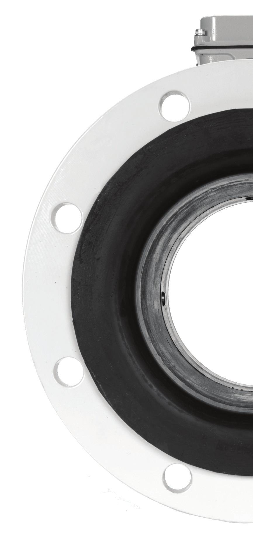

88 g Resources n i v r e s n o Saving Time Saving Money C Technology with a Mission info@seametrics.com nd Avenue South, Kent, Washington fax: LT /1/ Seametrics, Inc. Printed in the U.S.A
SeaMetrics Flow Meters and Flow Computers
 Distributed Products Fact Sheet and Flow Computers WTP-PVC body turbine flow meter WT-S Stainless steel body turbine flow meter TX115/215 Hottap insertion turbine flow meter FT420 Looppowered flow computer
IP80-Series FLOW SENSOR INSTRUCTIONS IP81 IP :2008 ISO CERTIFIED COMPANY IP80-SERIES FLOW SENSOR INSTRUCTIONS
 IP80-SERIES FLOW SENSOR INSTRUCTIONS IP80-Series FLOW SENSOR INSTRUCTIONS IP81 IP82 9 001:2008 ISO CERTIFIED COMPANY TABLE OF CONTENTS General Information Features, Specifications...Page 3 Installation
IP800-Series FLOW SENSOR INSTRUCTIONS IP810 IP :2008 ISO CERTIFIED COMPANY IP80-SERIES FLOW SENSOR INSTRUCTIONS
 IP80-SERIES FLOW SENSOR INSTRUCTIONS IP800-Series FLOW SENSOR INSTRUCTIONS IP810 IP820 9001:2008 ISO CERTIFIED COMPANY TABLE OF CONTENTS General Information Features, Specifications...Page 3 Installation
IP800-Series FLOW SENSOR INSTRUCTIONS IP810 IP :2008 ISO CERTIFIED COMPANY IP800-SERIES FLOW SENSOR INSTRUCTIONS
 -SERIES FLOW SENSOR INSTRUCTIONS -Series FLOW SENSOR INSTRUCTIONS IP810 IP820 9001:2008 ISO CERTIFIED COMPANY TABLE OF CONTENTS General Information Features, Specifications...Page 3 Installation Insertion
TX80-Series FLOW SENSOR INSTRUCTIONS TX81 TX :2008 ISO CERTIFIED COMPANY TX80-SERIES FLOW SENSOR INSTRUCTIONS
 TX80-SERIES FLOW SENSOR INSTRUCTIONS TX80-Series FLOW SENSOR INSTRUCTIONS TX81 TX82 9 001:2008 ISO CERTIFIED COMPANY TABLE OF CONTENTS General Information Specifications, Features...Page 1 Installation
IP800-Series. Insertion Paddlewheel Flow Sensor Instructions PROUDLY MADE IN THE USA
 IP800-Series Insertion Paddlewheel Flow Sensor Instructions PROUDLY MADE IN THE USA ISO 9001:2008 Certified Company TABLE OF CONTENTS General Information General Information...Page 3 Features...Page 3
IP800-Series. Insertion Paddlewheel Flow Sensor Instructions PROUDLY MADE IN THE USA
 IP800-Series Insertion Paddlewheel Flow Sensor Instructions PROUDLY MADE IN THE USA ISO 9001:2008 Certified Company TABLE OF CONTENTS General Information General Information...Page 3 Features...Page 3
TX800-Series FLOW SENSOR INSTRUCTIONS. TX81x TX82x 9 001:2008 ISO CERTIFIED COMPANY TX800-SERIES FLOW SENSOR INSTRUCTIONS
 TX800-SERIES FLOW SENSOR INSTRUCTIONS TX800-Series FLOW SENSOR INSTRUCTIONS TX81x TX82x 9 001:2008 ISO CERTIFIED COMPANY TABLE OF CONTENTS General Information Generial Information, Features...Page 3 Specifications...Page
TX101/201 Insertion Turbine Instructions
 TX101/201 Insertion Turbine Instructions General Information Ruby bearings and a non-drag pick-off give these adjustable insertion turbine flow sensors a wide flow and long life. A sensor detects the passage
EX80-Series ELECTROMAGNETIC FLOW SENSOR INSTRUCTIONS EX81 EX82 EX :2008 ISO CERTIFIED COMPANY
 EX80- SERIES ELECTROMAGNETIC FLOW SENSOR INSTRUCTIONS EX80-Series ELECTROMAGNETIC FLOW SENSOR INSTRUCTIONS EX81 EX82 EX83 9 001:2008 ISO CERTIFIED COMPANY TABLE OF CONTENTS General Information Features,
TX101/201 Insertion Turbine Instructions
 TX101/201 Insertion Turbine Instructions General Information Sapphire bearings and a non-drag pick-off give these adjustable insertion turbine flow sensors a wide flow and long life. A Hall-effect device
TX115/215 Hot-tap Insertion Turbine Instructions
 TX115/215 Hot-tap Insertion Turbine Instructions General Information These hot tap versions of the proven TX insertion flow sensors are designed to install or be serviced without depressurizing the pipe.
TX 115/215 Hot-tap Insertion Turbine Instructions
 TX 115/215 Hot-tap Insertion Turbine Instructions General Information These hot tap versions of the proven TX insertion flow sensors are designed to install or be serviced without depressurizing the pipe.
TX100/200-SERIES INSERTION TURBINE INSTRUCTIONS TX101/201 TX115/215 ISO 9001:2008 CERTIFIED COMPANY
 TX100/200-SERIES INSERTION TURBINE INSTRUCTIONS TX100/200-SERIES INSERTION TURBINE INSTRUCTIONS TX101/201 TX115/215 ISO 9001:2008 CERTIFIED COMPANY TABLE OF CONTENTS General Information Features, Specifications...Page
EM101 LOW FLOW MAGNETIC FLOWMETER INSTRUCTIONS
 Spec Tech Industrial 203 Vest Ave. Valley Park, MO 63088 Phone: 888 SPECTECH Email: sales@spectechind.com www.spectechind.com EM101 EM101 LOW FLOW MAGNETIC FLOWMETER INSTRUCTIONS LOW FLOW MAGNETIC FLOWMETER
EM 101 EM EM EM GENERAL INFORMATION. SPECIFICATIONS MATERIALS Wetted Materials - FLOW RANGE
 EM101 LOW FLOW MAGNETIC FLOW METER INSTRUCTIONS EM 101 LOW-FLOW MAGNETIC FLOW METER INSTRUCTIONS EM 101-025 EM 101-038 EM 101-050 GENERAL INFORMATION The EM101 is a small plastic-bodied electromagnetic
PSF50 Paddle flow switch
 Paddle Flow Switch Paddle Flow Switch PSF50 Paddle flow switch Paddle flap flow / no flow switch Economically priced flow/no flow paddle operated flow switch. Simple and reliable design for liquids up
WMX-series MUNICIPAL/INDUSTRIAL MAGMETER INSTRUCTIONS
 -series MUNICIPAL/INDUSTRIAL MAGMETER INSTRUCTIONS -SERIES MUNICIPAL/INDUSTRIAL MAGMETER INSTRUCTIONS 101 104 The Leader in Flow Meter Value Table of Contents General Information General Information,
SERIES TBS INSERTION TURBINE TBS-0XX TBS-1XX
 F- SERIES INSERTION TURBINE instructions -0XX -1XX Table of Contents GENERAL INFORMATION General Information Features, Specifications... Page 1 Installation Piping, Immersion, Positioning the Meter...
EX100/200-Series INSERTION MAGNETIC FLOW METER INSTRUCTIONS EX110 EX210 EX150 EX :2008 ISO CERTIFIED COMPANY
 EX100/200-SERIES INSERTION MAGNETIC FLOW METER INSTRUCTIONS EX100/200-Series INSERTION MAGNETIC FLOW METER INSTRUCTIONS EX110 EX210 EX150 EX250 9 001:2008 ISO CERTIFIED COMPANY TABLE OF CONTENTS General
TX100/200-SERIES INSERTION TURBINE. T X / S E R I E S I N S E R T I O N T U R B I N E instru c tions TX101/201 TX115/215
 INSERTION TURBINE instructions T X 1 0 0 / 2 0 0 - S E R I E S I N S E R T I O N T U R B I N E instru c tions AR CH IV ED TX100/200-SERIES TX101/201 TX115/215 Table of Contents General Information Features,
EX80 Series EX81 EX82. E X 8 0 S E R I E S E l e c t r o m a g n e t i C F l o w s e n s o r i n s t r u c t i o n s. The Leader in Flow Meter Value.
 E X S E R I E S E l e c t r o m a g n e t i C F l o w s e n s o r i n s t r u c t i o n s EX Series Electromagnetic FLOW SENSOR instructions EX EX The Leader in Flow Meter Value. Table of Contents General
ARCHIVED. EX80 Series. (Includes Dates 6/28/05 to 10/06) EX81 EX82
 EX81 EX82") E X S E R I E S E l e c t r o m a g n e t i C F l o w s e n s o r i n s t r u c t i o n s EX Series Electromagnetic FLOW SENSOR instructions EX EX The Leader in Flow Meter Value. Table of Contents General
E X S E R I E S E l e c t r o m a g n e t i C F l o w s e n s o r i n s t r u c t i o n s EX Series Electromagnetic FLOW SENSOR instructions EX EX The Leader in Flow Meter Value. Table of Contents General
S-Series. Low Flow Meter Instructions SPX SPT. Precision Flow Measurement An ONICON Brand PROUDLY MADE IN THE USA
 S-Series Low Flow Meter Instructions Precision Flow Measurement An ONICON Brand PROUDLY MADE IN THE USA ISO 9001:2008 Certified Company TABLE OF CONTENTS General Information General Information...Page
TURBINE METERS - WP Series
 TURBINE METERS - WP Series Operating Pressure 150 psi Maximum Operating Temperature Cold Water 105 F (40 ) 3 Layers Epoxy Coating SIZE 2" 3" 4" 6" 8" Max. Flow Rate GPM 400 850 1100 2600 4400 Transition
Seametrics. Flow Meter & Control Catal0. Aqua Technology Group Meters I Controls 'Equipment I Service
 Seametrics Flow Meter & Control Catal0 Distributed / Serviced By: Phone: (800) 513-89931 +1 (513) 298-1183 Seametncs Seametrics Products are covered by a Two Year Limited Warranty policy. Please visit
G2 Industrial Grade Meters
 G2 Industrial Grade Meters The unique modular approach of the Industrial Grade Meter line allows you to section 2: g2 industrial grade meters design a meter to match your specific application. Turbine
WMX-SERIES Flanged Magmeter
 9001:2008 ISO CERIFIED COMPANY FEAURES NSF/ANSI 61 Available (3 only) Built-in pulse output for data logging or telemetry Minimal straight pipe required Continuous battery or external power IP68 submersible
imag 4700 SERIES FLANGED MAGMETER
 SERIES r (Remote Display) p Features Easy setup Minimal straight pipe Mounted or remote rate & total Tamper-evident seal NSF-61 approved IP68 rated Right meter for Water & Wastewater Treatment Municipal
WMP-Series PLASTIC-BODIED MAGMETER INSTRUCTIONS 9001:2008 ISO CERTIFIED COMPANY WMP-SERIES PLASTIC-BODIED MAGMETER INSTRUCTIONS. 3 inch.
 -SERIES PLASTIC-BODIED MAGMETER INSTRUCTIONS -Series PLASTIC-BODIED MAGMETER INSTRUCTIONS 3 inch 2 inch 1 inch 9001:2008 ISO CERTIFIED COMPANY GENERAL INFORMATION and FEATURES GENERAL INFORMATION The -Series
SES. Stainless Single-Jet Meter Instructions PROUDLY MADE IN THE USA
 SES Stainless Single-Jet Meter Instructions PROUDLY MADE IN THE USA ISO 9001:2008 Certified Company TABLE OF CONTENTS General Information General Information...Page 3 Features...Page 3 Specifications...Page
AG2000 Irrigation Magmeter
 9001:2008 ISO CERIFIED COMPANY APPICAIONS Irrigation Chemigation Agricultural automation Well usage monitoring Dairy agoons FEAURES Simple as a mechanical meter No moving parts Minimal straight pipe required
SERIES FLMG MUNICIPAL/INDUSTRIAL MAGMETER INSTRUCTIONS
 F- SERIES MUNICIPAL/INDUSTRIAL MAGMETER INSTRUCTIONS TABLE OF CONTENTS General Information General Information, Features... Page 1 Specifications Specifications, Flow Range... Page 2 Installation and
EX100/200 Series. Insertion Magnetic Flow Meter Instructions. EX11x EX21x. EX15x EX25x PROUDLY MADE IN THE USA
 EX100/200 Series Insertion Magnetic Flow Meter Instructions EX11x EX21x EX15x EX25x PROUDLY MADE IN THE USA ISO 9001:2008 Certified Company TABLE OF CONTENTS General Information General Information...Page
ProSeries NEMA 4X SONIC-PRO. Engineering and Technical Data. Transit Time Ultrasonic Flowmeter. Industries, Ltd. s Ultrasonic Flow Meters
 ProSeries by Blue-White Industries, Ind. Ltd. Industries, Ltd. s SNIC-PR s SNIC-PR s S4 Transit Time Ultrasonic Flowmeter ½ thru 2 diameter Pipe Sizes Inline spool piece Advanced communications Data logging
ISTEC MAGNETIC METERS
 ISTEC MAGNETIC METERS MEASURE ANY CONDUCTIVE LIQUIDS OR SLURRIES (EVEN ABRASIVE OR CORROSIVE) WITH THE NEW MICROPROCESSOR-BASED MAGNETIC METER -- A QUALITY PRODUCT - SIMPLE - RELIABLE - AT AN AFFORDABLE
Positive Displacement Flowmeters
 Positive Displacement Flowmeters SRZ series Helical screw positive displacement flowmeters Positive Displacement Flowmeters Two highly accurate cycloid-shaped screw spindles mesh and rotate inside a cylindrical
Flow Meters & Instruments. Insertion Paddle Wheel & Magnetic Flow Meters Flow & Anaytical Instruments. Technical Catalogue
 Flow Meters & Instruments Insertion Paddle Wheel & Magnetic Flow Meters Flow & Anaytical Instruments Technical Catalogue PDF Published October 19, 2017 flow sensors Type F3.01 Direct Mount Flow Sensors
AG2000 IRRIGATION MAGMETER INSTRUCTIONS
 AG2000 IRRIGATION MAGMETER INSTRUCTIONS AG2000 IRRIGATION MAGMETER INSTRUCTIONS FEATURES Rate and total indicator Powder-coated diecast-aluminum electronics housing Cross-drilled screws (2) for tamper-evidence
FT430/440/450 RATE/TOTAL INDICATOR INSTRUCTIONS
 FT430/440/450 RATE/TOTAL INDICATOR INTRUCTION FT430/440/450 RATE/TOTAL INDICATOR INTRUCTION Optional Protective Cover Closed 9001:2008 IO CERTIFIED COMPANY PROUDLY MADE IN THE UA TABLE OF CONTENT General
Appendix. Clearance. Skewed profiles. Application Schematics
 Appendix Application Schematics The purpose of the application schematics is to show different applications and the best sensor location for a particular application. Clearance Because the sensor will
A1 Commercial Grade Meters
 A1 Commercial Grade Meters Commercial Grade Meters are designed as self-contained, battery powered units. These indicating meters come in Aluminum or Nylon only. A1 Meters are not field serviceable like
MFM220 & MFM220DC Plastic-Bodied Magmeter
 APPLICATIONS Usage monitoring, such as: Industrial wastewater discharge monitoring Cooling tower deduct metering Heap leach mining discharge monitoring Well monitoring Turf and landscape water monitoring
FPI Mag FULL PROFILE INSERTION ELECTROMAGNETIC FLOW METER MODELS 394L AND 395L MAG METER SUBMITTAL
 FPI Mag FULL PROFILE INSERTION ELECTROMAGNETIC FLOW METER MODELS 394L AND 395L MAG METER SUBMITTAL From McCROMETER 3255 WEST STETSON AVENUE HEMET, CA 92545 Phone (95) 652-68 Toll Free (800) 220-2279 Fax
2100 Turbine Flow Sensor
 200 Turbine Flow Sensor Description Engineered specifically for small pipe diameter applications, the Signet 200 Turbine Flow Sensor provides accurate readings in two flow ranges: 0.3 to 3.8 lpm and 3
Signet 2551 Magmeter Flow Sensor
 Signet 2551 Magmeter Flow Sensor Available in a variety of wetted materials and ideal for pipe sizes up to DN900 (36 in.) Features Test certificate included for -X0, -X1 Patented Magmeter technology No
Electromagnetic Flowmeters. Product Overview.
 Electromagnetic Flowmeters Product Overview www.lcmeter.com Premier products, premier performance Liquid Controls offers a broad selection of electromagnetic (Mag) flow meters for industrial and water
Rosemount 8750WA Magnetic Flowmeter System For Water and Wastewater Industries
 Product Data Sheet January 214 813-1-475, Rev FA Rosemount 875WA Magnetic Flowmeter System For Water and Wastewater Industries THE 875WA MAGNETIC FLOWMETER Rosemount reliability in a customized offering
flow x3 flow monitoring
 flow x3 flow monitoring The FlowX3 System includes a complete range of paddle wheel flow sensors, instruments and sensor installation fittings. Also included are insertion type electromagnetic flow transmitters.
Hydro-Flow 2200 Fixed Insertion Vortex Flow Meter
 A trademark of Spirax Sarco, Inc. Hydro-Flow 2200 Fixed Insertion Vortex Flow Meter Description The Hydro-Flow Model 2200 fixed insertion vortex flow meter was designed specifically for water flow measurement,
Flow meter Type Recordall (RCDL)
") Badger Meter Europa GmbH Nürtinger Str. 76 72639 Neuffen (Germany) Tel. +49-7025-9208-0 Fax +49-7025-9208-15 www.badgermeter.de badger@badgermeter.de Flow meter Type Recordall (RCDL) Bronze model Features
Badger Meter Europa GmbH Nürtinger Str. 76 72639 Neuffen (Germany) Tel. +49-7025-9208-0 Fax +49-7025-9208-15 www.badgermeter.de badger@badgermeter.de Flow meter Type Recordall (RCDL) Bronze model Features
A1 Commercial Grade Meters
 A1 Commercial Grade Meters Commercial Grade Meters are designed as self-contained, battery powered units. These indicating meters come in Aluminum or Nylon only. A1 Meters are not field serviceable like
Instructions EM 101 Low Flow Electromagnetic Flow Meters
 PDF Published June 3, 2004 Instructions EM 101 Low Flow Electromagnetic Flow Meters Installation Mounting The EM 101 model has a flow meter unit and a separate control unit containing a LCD display. The
INDUSTRIAL METER CATALOG version seven
 INDUSTRIAL METER CATALOG version seven TABLE OF CONTENTS G Series Precision Meters... Build-Your-Own... 4 G Series Meter Number Reference... 5 Stainless Steel GBT, GIT & GNT... 6 Stainless Steel GBP, GIP
A1 SERIES COMMERCIAL GRADE METERS A1 SERIES COMMERCIAL GRADE METERS
 COMMERCIAL GRADE METERS Look for the silver label! Look for the silver label! COMMERCIAL GRADE METERS Commercial Grade Meters are designed as self-contained, battery powered units. These indicating meters
FLS F6.60 MAGMETER FLOW SENSOR INSERTION FLOW SENSORS APPLICATIONS MAIN FEATURES
 FLS F6.60 MAGMETER FLOW SENSOR The new F6.60 and F6.63 are flow meters without moving mechanical parts which can be applied for the measurement of dirty liquids so long as they are conductive and homogeneous.
The full WeatherTRAK Flow3 Installation and Maintenance Manual is available online at
 Installation Manual INTRODUCTION The full WeatherTRAK Flow Installation and Maintenance Manual is available online at www.weathertrak.com General Description A WeatherTRAK Flow combines a hydraulic master
Industrial Meter Catalog
 Industrial Meter Catalog SEE INSIDE FOR THESE NEW PRODUCTS: GBM Series Mini Batcher... page 66 LM50M Mechanical Lube Meter... page 52 TM Digital Pulse Meter... page 53 VERSION 6 2008 888-996-3837 www.gpi.net
M SERIES Multi-Jet Cold Water Meter
 M SERIES Multi-Jet Cold Water Meter /4 1 1-1/2" 2" Maximum Flow GPM 0 0 1 Minimum Flow GPM.2.7 1. 2.0 Maximum Operating Pressure 0 psi Maximum Operating Temperature F ( C) Also Available in Hot Water Applications
Propeller. Flowmeter. Technology. For the Real World.
 Propeller Flowmeter Technology For the Real World. Propeller Flowmeters Long-lasting Stainless Steel Ball Bearings. Factory lubricated and protected from flow stream. Epoxy-Coated Carbon Steel Body. All
Industrial OG meter series IOG Inline and flanged oval gear meter
 Badger Meter Europa GmbH Nürtinger Str. 76 72639 Neuffen (Germany) Tel. +49-7025-9208-0 Fax +49-7025-9208-15 www.badgermeter.de badger@badgermeter.de Industrial OG meter series IOG Inline and flanged oval
F-2000 MODEL RT INSTRUCTION MANUAL. Blue-White. Industries, Ltd.
 F-2000 MODEL RT INSTRUCTION MANUAL Blue-White Industries, Ltd. R PT Sarana Prima Enguna Jl.Gunung Sahari Raya 84 C - Jakarta 10610 Phone: 021-420-0045 Fax: 021-420-0483 E mail: info@spe.co.id Website:
Distributed by: M&M Control Service, Inc MICRO-FLO MICRO-FLO
 Digital Paddlewheel Flow meter Operating Manual Blue-White Industries, Ltd. Page 2 TABLE OF CONTENTS 1...Introduction...2 2...Features...3 3...Model number matrix...3 4...Specifications...4 4.1..Temperature
digital flow meters BW Digi-Meter F-1000
 F-1000 Series paddle wheel flow meters provide the performance and features of electronic meters, without the need for an external electricity supply. A large range of installation tees and saddles enables
RESISTIVITY MONITOR/CONTROLLERS
 RESISTIVITY MONITOR/CONTROLLERS Installation Operation Maintenance User Manual for Models: 750, 752, 753, 762 2450 Impala Drive Carlsbad, CA 92010-7226 USA Tel: 1-760-438-2021 Fax: 1-800-869-7668 / 1-760-931-9189
BI-DIRECTIONAL INSERTION FLOW TRANSDUCER
 DUALPULSE BI-DIRECTIONAL INSERTION FLOW TRANSDUCER INSTRUCTION MANUAL DUALPULSE LOCK 1.1 General arrangement Thank you for purchasing a Dualpulse Flowmeter. It is important that you read this manual to
INSTRUMENTATION & CONTROL
 Irrigation Controller.................... 172 Window Controller.................... 174 Water Meter Controller.................. 176 Digital Level Switch.................... 177 Filtration Controller Set..................
UTM10 Series Ultrasonic Transit-time Flowmeters
 Page 1 of 5 TI-P197-01 MI Issue 1 UTM10 Series Ultrasonic Transit-time Flowmeters Description UTM10 ultrasonic flow and energy meters clamp onto the outside of pipes and do not make contact with the internal
CONTROLLERS & SPECIAL VALVES
 CONTROLLERS & SPECIAL VALVES G75-C 1, 2 & 4 Valve Controllers.... 70 G75-C-1W & 1W+ Window Controller... 72 G75-DP Differential Pressure Switch.....................................................................
FPI-X FULL PROFILE INSERTION ELECTROMAGNETIC FLOW METER MODEL 395X MAG METER SUBMITTAL
 FPI-X FULL PROFILE INSERTION ELECTROMAGNETIC FLOW METER MODEL 395X MAG METER SUBMITTAL From McCROMETER 3255 WEST STETSON AVENUE HEMET, CA 92545 Phone (951) 652-6811 Toll Free (800) 220-2279 Fax (951) 652-3078
EX800-Series. Electromagnetic Flow Sensor Instructions PROUDLY MADE IN THE USA
 EX800-Series Electromagnetic Flow Sensor Instructions PROUDLY MADE IN THE USA ISO 9001:2008 Certified Company TABLE OF CONTENTS General Information General Information...Page 3 Features...Page 3 Specifications...Page
KEL DIFFERENTIAL PRESSURE FLOWMETERS
 KEL DIFFERENTIAL PRESSURE FLOWMETERS Flow Pressure Level Temperature measurement monitoring control Rugged Metal Construction Flow Rate to 2000 GPM Linear Scale For Horizontal or Vertical Pipes Threaded
The Vario motor-driven pump series from ProMinent Adaptable to a wide range of applications VARIO METERING PUMP
 The Vario motor-driven pump series from ProMinent Adaptable to a wide range of applications VARIO METERING PUMP ProMinent Modular design allows selection of the features you need Three diaphragm sizes
Sidel Therm & CO 2 Counter Instruction & Installation Manual
 Sidel Therm & CO 2 Counter Instruction & Installation Manual P.O. Box 1868 Atascadero, CA 93423 800-668-5003 Fax: 805-464-0504 Sid Abma, President www.sidelsystems.com Table Of Contents System Overview..............................
LEVEL AND FLOW MEASUREMENT WS131 FLOW METER USER MANUAL.
 LEVEL AND FLOW MEASUREMENT WS131 FLOW METER USER MANUAL www.enoscientific.com Eno Scientific PO Box 1586 Hillsborough, NC 27278 USA www.enoscientific.com 910-778-2660 Copyright Notice Copyright 2015 Eno
Pipe fi ttings MUST be installed by a certifi ed welder only. Signet will not assume liability of any kind for improper fi tting installations.
 Signet 50 High Performance Flow Sensor English *3-50.090* 3-50.090 C 05/06 English SAFETY INSTRUCTIONS 1. Do not remove from pressurized lines.. Do not exceed maximum temperature/pressure specifi cations.
Turbidity and Suspended Solids Transmitter
 Data Sheet 5.1 We reserve the right to continuously improve our products and make any change in the stated specifications and dimensions without prior notice. DK: NO: SE: NL: USA: AUS: +45 45 56 06 56
Model TUR-200D Turbine Flowmeter
 General Specifications Model TUR-200D Turbine Flowmeter Liquid flows through the turbine housing causing an internal rotor to spin. As the rotor spins, an electrical signal is generated in the pickup coil.
Pipe fittings MUST be installed by a certified welder only. +GF+ SIGNET will not assume liability of any kind for improper fitting installations.
 +GF+ SIGNET 0 High Performance Flow Sensor (English) -0.090- F-/99 English SAFETY INSTRUCTIONS. Do not remove from pressurized lines.. Do not exceed maximum temperature/pressure specifications.. Do not
Installation & Operation Manual
 SDI Series Insert Style Flow Sensors Installation & Operation Manual BadgerMeter, Inc. PN# 72034 1-09 Rev B8 (This page intentionally left blank.) 2 Introduction The Data Industrial SDI Series impeller
EGM1100C MAGMAX. Compact Electromagnetic Flowmeter GENERAL FEATURES STANDARD SPECIFICATION. General Specification
 EGMC Compact Electromagnetic Flowmeter GENERA MAGMAX EGMC is the compact type electromagnetic flowmeter with a converter EGC mounted integrally on a primary head EGS lined with fluorocarbon resin PFA.
Low Profile Insertion Vortex
 Low Profile Insertion Vortex Product Features The same insertion meter can measure Steam, Gases or Liquids. Standardize on an insertion bar that can measure line sizes 2 24 Heavy Duty & Maintenance Free
KEL. Heavy Duty Differential Pressure Flowmeters
 Heavy Duty Differential Pressure Flowmeters measuring monitoring analyzing KEL Rugged Metal Construction Flow Rates up to 2000 GPM Linear Scales For Horizontal or Vertical s Threaded or Wafer Style s Able
Ultra Mag SUBMITTAL PACKAGE
 SUBMITTAL PACKAGE Date: McCROMETER, INC. 3255 WEST STETSON AVENUE HEMET, CA 92545 PHONE (951) 652-6811 TOLL FREE (800) 800-8804 FAX (951) 652-3078 www.mccrometer.com 3255 WEST STETSON AVENUE HEMET, CALIFORNIA
Conductivity meter. PLC Solenoid valve. Type Type On/Off Diaphragm valve. Valve islands
 Conductivity meter Configurable outputs: two transistor and single or dual analog 4... 20 ma Removable backlighted display Universal process connection Type can be combined with... Three cell constants
Insertion turbine INSTRUCTION SHEET. TECHNICAL PRODUCT
 TECHNICAL PRODUCT INSTRUCTION SHEET Insertion turbine OVERVIEW These insertion flow transducers provide a cost effective and simple means of measuring the flow of a wide range of low viscosity liquids.
Model FVP General Specification. Flanged Vortex Plate. Product Features
 Flanged Vortex Plate Product Features Our Inline meters can measure Steam, Gases or Liquids. Measures two times lower than any other Vortex Meter. Heavy Duty & Maintenance Free Design C&C Machined from
RCM - Direct Reading Flowmeters
 Compact Design Easy to Install Horizontal or Vertical Installation Flow Rates up to 3000 GPM (Liquid) or 20000 SCFM (Gas) Low Pressure Drop Optional Alarms and Output Signals Accuracy: ± 3% of full scale
SOLAR LIGHTING CONTROLLER SUNLIGHT MODELS INCLUDED IN THIS MANUAL SL-10 SL-10-24V SL-20 SL-20-24V
 SOLAR LIGHTING CONTROLLER OPERATOR S MANUAL SUNLIGHT MODELS INCLUDED IN THIS MANUAL SL-10 SL-10-24V SL-20 SL-20-24V 10A / 12V 10A / 24V 20A / 12V 20A / 24V 1098 Washington Crossing Road Washington Crossing,
Features/Benefits INSTALL IT & FORGET IT FEATURES & BENEFITS
 Features/Benefits INSTALL IT & FORGET IT The ForceMeter TM offers the same rugged design for which the Niagara Meters brand is known. The ForceMeter is ideal for applications including water, compressed
SECTION ELECTRONIC ACTUATED PRESSURE REDUCING VALVES AND ACCESSORIES
 SECTION 33 12 16.05 REDUCING VALVES AND ACCESSORIES PART 1 - GENERAL 1.1 THE REQUIREMENT A. The Electronic Actuated Pressure Reducing Valve (PRV) shall maintain a constant downstream pressure regardless
User Manual. T6 Tachometer. Online: Telephone: P.O. Box St. Petersburg, Florida 33736
 User Manual T6 Tachometer Online: www.phareselectronics.com Telephone: 727-623-0894 P.O. Box 67251 St. Petersburg, Florida 33736 Table of Contents Overview... 1 Description... 1 Wiring... 1 T6 Tachometer
SOLENOID DRIVEN DOSING PUMPS MX series
 SOLENOID DRIVEN DOSING PUMPS MX series www.fwtsystems.it INTRODUCING MX SERIES FWT is pleased to introduce MX solenoid driven dosing pumps, a new series which will enable to widen the product range covering
Cerama~Flow CF900. Wear Resistant Magnetic Slurry Flowmeter. Superior Measurement Systems.
 Cerama~Flow CF900 Wear Resistant Magnetic Slurry Flowmeter Superior Measurement Systems www.hmagroup.com.au Technical Specification NautiFlow NF-1 Battery Powered Electromagnetic flowmeter Intelligent
Signet 2517 Brass Paddlewheel Flow Sensor * *
 Signet 2517 Brass Paddlewheel Flow Sensor -250.090 English -2517.090 Rev. F 11/06 English SAFETY INSTRUCTIONS 1. Do not remove from pressurized lines. 2. Do not exceed maximum temperature/pressure specifi
Water and Chemical Batching. Precision Measurement for Ready-Mix and Concrete Batch Plants. Concrete Meter Overview
 Water and Chemical Batching. Precision Measurement for Ready-Mix and Concrete Batch Plants. Concrete Meter Overview Every drop counts. Measure and precisely control the amount of water and chemical additives
Product Data Sheet. Flow Sensors. Insert Style Flow Sensors SDI Series DESCRIPTION HOT TAP SENSORS (OPTIONAL) APPLICATIONS FUNCTIONALITY
 APPLICATIONS FUNCTIONALITY") DESCRIPTION Flow Sensors Insert Style Flow Sensors SDI Series The Data Industrial SDI Series insert flow sensors from Badger Meter offer accurate liquid flow measurement in closed pipe systems in an easy
DESCRIPTION Flow Sensors Insert Style Flow Sensors SDI Series The Data Industrial SDI Series insert flow sensors from Badger Meter offer accurate liquid flow measurement in closed pipe systems in an easy
Rosemount 8750WB Magnetic Flowmeter System
 Rosemount 8750WB Magnetic Flowmeter System for Utility, Water, and Wastewater Applications Product Data Sheet 00813-0200-4750 Rev AA THE 8750W MAGNETIC FLOWMETER Rosemount reliability customized for Water,
Options guide. Electromagnetic flowmeters. M9xx
 Options guide Electromagnetic flowmeters M9xx Ordering codes Model Description M 910 -V0 0 0 0 DN50 PN16 Example Sensor M Basic Ex Ex certified (remote version only) Transmitter 910E Economic version 910
F-2700 SERIES INSERTION VORTEX FLOW METER
 F-2700 SERIES INSERTION VORTEX FLOW METER APPLICATIONS Saturated steam Hot water to 500 F (260 C) standard 750 F (400 C) optional Applications with optional pressure sensor Superheated steam to 500 F (260