INDEX Welcome 1.2 Contacting Powergrid Solutions, Inc. 1.3 Terms Of Usage 1.4 Product Codes and Descriptions
|
|
|
- Rosalyn Preston
- 5 years ago
- Views:
Transcription
1 INDEX SECTION 1 INTRODUCTION 1.1 Welcome 1.2 Contacting Powergrid Solutions, Inc. 1.3 Terms Of Usage 1.4 Product Codes and Descriptions SECTION 2 PADMOUNTED ENCLOSURES/CABLE SWITCHING/TERMINATING GEAR 2.1 Padmounted Enclosures, Model SECL 2.2 Padmounted Sectionalizer Enclosure, Model SSED 2.3 Padmounted Cable Switching Gear (Deadfront), Model SCSD 2.4 Padmounted Cable Terminating Gear, Models STEN, STEI, STMV, SECTION 3 PADMOUNTED FUSEGEAR / SWITCHGEAR 3.1 Padmounted Fuse Gear (Deadfront), Model SFGD 3.2 Padmounted Fuse Gear (Livefront), Model SFGL 3.3 Padmounted Switchgear (Deadfront), Model SPD (2/4 Circuit) 3.4 Padmounted Switchgear (Livefront), Model SPL, (2/4 Circuit) 3.5 Padmounted Switchgear (Deadfront), Model SSGD (6/8 Circuit) 3.6 Padmounted Switchgear (Livefront), Model SSGL, (6/8 Circuit) SECTION 4 PADMOUNTED PRIMARY METERING GEAR 4.1 Padmounted Primary Metering (Deadfront), Models SPMD and SPMG 4.2 Padmounted Primary Metering (Livefront), Model SPML SECTION 5 CAPACITOR BANKS 5.1 Padmounted Capacitor Banks (Deadfront and Livefront), Models SCBD and SCBL 5.2 Metal-Enclosed Capacitor Banks, Model SCBM, Types M1 and M2 5.3 Metal-Enclosed Multi-Step Capacitor Banks, Model SCBM, Types S1 and S2 SECTION 6 SWITCHGEAR / PARALLELING SWITCHGEAR 6.1 Metal-Enclosed Switchgear, Model SMEG 6.2 Metal-Clad Switchgear, Model SMCG 6.3 Hybrid Switchgear, Model SMECG 6.4 Paralleling Switchgear, Model MVPS 6.5 Relay and Control Panels 6.6 Low Voltage Switchgear 6.7 Powergrid Solutions FlexAisle SECTION 7 REFERENCES 7.1 Terms and Conditions 7.2 Glossary 7.3 ANSI / IEEE Device Numbers 7.4 Disclaimer 1.0.0
2 WELCOME to POWERGRID SOLUTIONS INC. s PRODUCT CATALOG To confirm you are looking at the most recent version of the Powergrid Solutions product catalog or to find a listing of your Powergrid Solutions representative, please log on to Welcome: Thank you for reviewing Powergrid Solutions Inc. s Product Catalog that contains our fine line of equipment for the following applications: Power Generation Power Reliability Power Quality Power Transmission and Distribution T & D Powergrid Solutions Inc. has been in business for over 30 years. All of our products are produced in our new, state of the art production facility located in Oshkosh, WI. We serve a broad base of customers ranging from Commercial and Industrial accounts, Utilities, to Alternative Energy markets. Our staff has the training and experience working with a variety of components to meet all your medium and low voltage needs. We pride ourselves on knowing our customers, taking an active interest in their needs and providing quality equipment. These are just a few of the reasons we have such a high level of repeat business. Catalog Doc. Number SICO1028A 1.1.1
3 CONTACTING POWERGRID SOLUTIONS INC. Powergrid Solutions Inc. HQ: 3110 Progress Drive Oshkosh, WI PH: PH: FX: E-M: Web:
4 TERMS of USAGE This catalog and the information contained within is the exclusive copyright material of: Powergrid Solutions Inc Progress Drive Oshkosh, WI Or the appropriate copyright owner of the documents as indicated. Your usage of the contents of this catalog in any format or media is conditional upon your acceptance of the following terms. If you do not accept the terms, refrain from using any of the contents, documents and/or information. Any unauthorized duplication or reproduction of this material without the express written consent of Powergrid Solutions Inc. is strictly prohibited under penalty of law. All information, documents, graphics, white papers, brochures, software, etc. (collectively referred to as documents ) located in this catalog in any form or media format are copyrighted by the applicable companies as indicated on the documents. Documents are the intellectual property of their creators and all rights are reserved by the appropriate companies unless noted otherwise. You are permitted to view the documents for conducting your normal course of business however all copyright notices shall remain intact. You may not re-distribute the documents in any way that may conflict with the copyright laws and notices. You may not use the documents in competition with, or to reverse engineer the products or services of Powergrid Solutions Inc. The documents are provided as is. Documents are considered to be recommended guidelines. Documents may contain errors or omissions, and Powergrid Solutions Inc., their employees, and other companies creating the documents do not make any warranty, express or implied, or assume any legal liability or responsibility for the correctness, accuracy, completeness, or usefulness of the documents or any information they contain. Powergrid Solutions Inc. reserves the right to change the specifications in their respective documents or their contents from time to time without notice
5 PRODUCT CODES AND DESCRIPTIONS SECTION 2 SECL SSED SCSD STEN STEN-EZ STMV SECTION 3 SFGD SFGL SPD SPL SSGD SSGL SECTION 4 SPMD SPMG SPML SECTION 5 SCBD SCBL SCBM-M1 SCBM-M2 SCBM-S1 SCBM-S2 SECTION 6 SMEG SMCG SMECG LVSG LVPS MVPS RCP MISC PADMOUNTED ENCLOSURES/CABLE SWITCHING/TERMINATING GEAR Padmount Medium Voltage Enclosure Padmount Sectionalizer Enclosure Padmount Cable Switching Enclosure Deadfront Padmount Termination Enclosure 600V w/o CT s Padmount Termination Enclosure Padmount Termination Enclosure Medium Voltage 5-35kV PADMOUNTED FUSEGEAR / SWITCHGEAR Padmount Fusegear Deadfront Padmount Fusegear Livefront Padmount Switchgear Deadfront Padmount Switchgear Livefront Padmount Switchgear Deadfront 6 Bay Padmount Switchgear Livefront 6 Bay PADMOUNTED PRIMARY METERING GEAR Padmount Primary Metering Deadfront Padmount Primary Metering Deadfront with GE Transformer Padmount Primary Metering Livefront CAPACITOR BANKS / POWER FACTOR CORRECTION Padmount Capacitor Bank Deadfront Padmount Capacitor Bank Livefront Metal-Enclosed Capacitor Bank with Single Side Access Metal-Enclosed Capacitor Bank with Double Side Access Multi-Step Capacitor Bank with Single Side Access Multi-Step Capacitor Bank with Double Side Access SWITCHGEAR / PARALLELING SWITCHGEAR Metal-Enclosed Switchgear Metal-Clad Switchgear Metal-Enclosed / Metal-Clad Switchgear Low Voltage Switchgear Low Voltage Paralleling Switchgear Medium Voltage Paralleling Switchgear Relay & Control Panels Miscellaneous 1.4.1
6 PADMOUNTED ENCLOSURE Model SECL. SIDE VIEW FRONT VIEW Application: BASE PLAN Powergrid Solutions (PSI) padmount enclosures are perfect for enclosing components that need protection from the environment. Our padmount enclosures usually feature a completely open bottom which makes them ideal for installing over a ground sleeve or concrete pad in an underground power system. The main purpose of an enclosure is to house and protect electrical switchgear components that must be out of the elements. The enclosures are available in almost any size and we offer options for mounting strut in the bottom of the enclosure to allow for secure mounting of components. A door or multiple doors gives access to the interior allowing the flexibility of wiring components. It s available in a variety of metals to deal with any environmental issues. The PSI design fully meets and exceeds all IEEE and ANSI standards


7 PADMOUNTED ENCLOSURE CONSTRUCTION FEATURES Lifting provisions with removable lifting plates and blind-tapped bolt holes. 2. Stainless steel hinges, loose joint pin, allows doors to be removed in the open position point positive mechanism with recessed penta-bolt 4. Door Stay Arms 6. No-Drip insulating compound on inside of roof 7. Manufacture s data plate, noncorrosive, stamped and attached to enclosure. 8. Warning and identification labels per IEEE, NEC & NFPA. 9. All-welded construction. 5. Cross Kinked Roof 2.1.2

8 PADMOUNTED ENCLOSURE CONSTRUCTION FEATURES Lifting provisions with removable lifting plates and blind-tapped bolt holes. 2. Stainless steel hinges, loose joint pin, allows doors to be removed in the open position point positive mechanism with recessed penta-bolt 4. Door Stay Arms 6. No-Drip insulating compound on inside of roof 7. Manufacture s data plate, noncorrosive, stamped and attached to enclosure. 8. Warning and identification labels per IEEE, NEC & NFPA. 9. All-welded construction. 5. Cross Kinked Roof 2.1.3
9 PADMOUNTED ENCLOSURE Model SECL. Catalog Number Selection Sheet. To be used in conjunction with Factory Check Sheet. MODEL DIMENSIONS S E C L ENCLOSURE MATERIAL SPECIAL DESIGNATIONS HEIGHT WIDTH DEPTH AL - ALUMINUM GA - GALVANNEAL MS - MILD STEEL SS - STAINLESS STEEL EXAMPLE: SECL MS-XXXX PADMOUNT ENCLOSURE, 15 KV, 30 x 66 x 22, CABINET IS CONSTRUCTED OF MILD STEEL
10 PADMOUNTED ENCLOSURE Model SECL. Factory Check Sheet. To be used in conjunction with Catalog Number Selection Sheet. ENCLOSURE: Material: A36 Mild Steel A60 Galvanneal Steel 304 L Stainless Steel 5052-H32 Aluminum Paint Finish: Green. Munsell No., 7GY 3.29/1.5 Gray (ANSI 70). Munsell No., 8.3G 7.0/0.4 Gray (ANSI 61). Munsell No., 8.3G 6.10/0.54 Other: 3-Point Latch Type: Penta-Head Bolt Hex-Head Bolt Louvers for enclosure ventilation. Insulation No-Drip Compound. Applied to the inside surface of the enclosure roof to prevent condensation. Base Undercoating. Applied to the bottom 2 of the enclosure. (Not required for Stainless Steel enclosures.) Specials: 2.1.5
11 PADMOUNTED SECTIONALIZER ENCLOSURE (DEADFRONT) Model SSED, 5-35kV FRONT VIEW SIDE VIEW Application: BASE PLAN Powergrid Solutions (PSI) Padmount Sectionalizing Enclosures provides Customers in Utility, Commercial, and Industrial markets a safe way to terminate multiple service feeds into one weatherproof enclosure. Padmount Cable Sectionalizing enclosures are commonly found where future power system expansion is needed such as plant expansions or other areas where load requirements increase. Our Padmount Sectionalizing Enclosures are used in medium voltage underground power systems to provide a cable splicing or termination point using medium voltage junction modules in systems where connecting, looping, or tapping is needed. PSI Padmount Cable Sectionalizing Enclosures are customizable to provide the customer the most convenient design for the needs of the specific power system it s being installed on. The enclosure is available in a variety of metals to deal with any environmental issues. The PSI design fully meets and exceeds all IEEE and ANSI standards
 6.")
12 PADMOUNTED SECTIONALIZING CABINET CONSTRUCTION FEATURES Lifting provisions with removable lifting plates and blind-tapped bolt holes. 2. Stainless steel hinges, loose joint pin, allows doors to be removed in the open position point positive mechanism with recessed penta-bolt 4. Door Stay Arms 5. No-Drip insulating compound on inside of roof (Option) 6. Manufacture s data plate, noncorrosive, stamped and attached to enclosure. 7. Warning and identification labels per IEEE, NEC & NFPA. 8. All-welded construction. 9. Universal Mounting Plate 10. Junction Modules **Optional** 2.2.2
 6.")
13 PADMOUNTED SECTIONALIZING CABINET CONSTRUCTION FEATURES Lifting provisions with removable lifting plates and blind-tapped bolt holes. 2. Stainless steel hinges, loose joint pin, allows doors to be removed in the open position point positive mechanism with recessed penta-bolt 4. Door Stay Arms 5. No-Drip insulating compound on inside of roof (Option) 6. Manufacture s data plate, noncorrosive, stamped and attached to enclosure. 7. Warning and identification labels per IEEE, NEC & NFPA. 8. All-welded construction. 9. Universal Mounting Plate 10. Junction Modules **Optional** 2.2.3
14 PADMOUNTED SECTIONALIZER ENCLOSURE (DEADFRONT) Model SSED, 5-35kV Catalog Number Selection Sheet. To be used in conjunction with Factory Check Sheet. MODEL STYLE S S E D DIMENSIONS JUNCTION MODULES ENCLOSURE MATERIAL PHASE SPECIAL DESIGNATIONS VOLTAGE (KV) HEIGHT WIDTH DEPTH AL - ALUMINUM GA - GALVANNEAL MS - MILD STEEL SS - STAINLESS STEEL WJM - NJM - WITH JUNCTION MODULES WITHOUT JUNCTION MODULES EXAMPLE: SSED NJM-MS-XXXX PADMOUNT SECTIONALIZER, 3 PHASE, 15 KV, 30 x 66 x 22, WITHOUT JUNCTION MODULES, CABINET IS CONSTRUCTED OF MILD STEEL
15 PADMOUNTED SECTIONALIZER ENCLOSURE (DEADFRONT) Model SSED, 5-35kV Factory Check Sheet. To be used in conjunction with Catalog Number Selection Sheet. RATINGS: Nominal System Voltage/ Maximum Design Voltage Basic Insulation Level (BIL) Continuous Current (Line) Continuous Current (Load) / kv 5 kv, 60 kv BIL 15 kv, 95 kv BIL 25 kv, 125 kv BIL 35 kv, 150 kv BIL Other kv, kv BIL 200 amp 600 amp 1200 amp (consult factory) 200 amp 600 amp ENCLOSURE: Material: A36 Mild Steel A60 Galvanneal Steel 304 L Stainless Steel 5052-H32 Aluminum Paint Finish: Green. Munsell No., 7GY 3.29/1.5 Gray (ANSI 70). Munsell No., 8.3G 7.0/0.4 Gray (ANSI 61). Munsell No., 8.3G 6.10/0.54 Other: 3-Point Latch Type: Penta-Head Bolt Hex-Head Bolt Louvers for enclosure ventilation. Insulation No-Drip Compound. Applied to the inside surface of the enclosure roof to prevent condensation. Base Undercoating. Applied to the bottom 2 of the enclosure. (Not required for Stainless Steel enclosures.) Ground Bails. (Located in the Deadfront). Interface Bushing Well Inserts. (200 amp only). Specials: 2.2.5
16 PADMOUNTED CABLE SWITCHING GEAR (DEADFRONT) Model SCSD, 5-35 kv. 200 and 600 Ampere, Non-Fused. Single and Three Phase. FRONT VIEW REAR VIEW Application: Powergrid Solutions (PSI) Padmount Cable Switching Gear provides Customers in Utility, Commercial, and Industrial markets a safe way to terminate multiple service feeds into one weatherproof enclosure. Padmount Cable Switching Gear is commonly found where future power system expansion is needed such as plant expansions or other areas where load requirements increase. These enclosures are used in medium voltage underground power systems to provide a cable splicing or terminating point on Bushings or Bushing Wells depending on system amperage. PSI Padmount Cable Switching Gear is customizable to provide the customer the most convenient design for the needs of the specific power system it s being installed on. The enclosure is available in a variety of metals to deal with any environmental issues. The PSI design fully meets and exceeds all IEEE and ANSI standards


17 PADMOUNTED CABLE SWITCHING GEAR CONSTRUCTION FEATURES Lifting provisions with removable lifting plates and blind-tapped bolt holes. 2. Stainless steel hinges, loose joint pin, allows doors to be removed in the open position point positive mechanism with recessed penta-bolt 4. Door Stay Arms 6. No-Drip insulating compound on inside of roof 7. Manufacture s data plate, noncorrosive, stamped and attached to enclosure. 8. Warning and identification labels per IEEE, NEC & NFPA. 9. All-welded construction. 5. Cross Kinked Roof 2.3.2
18 VOLTAGE (KV) PHASE PADMOUNTED CABLE SWITCHING GEAR (DEADFRONT) Model SCSD, 5-35 kv. 200 and 600 Ampere, Non-Fused. Single and Three Phase. Catalog Number Selection Sheet. To be used in conjunction with Factory Check Sheet. MODEL STYLE NUMBER OF LINE TERMINALS AMPERAGE LINE TERMINALS (MAX) NUMBER OF LOAD TERMINALS AMPERAGE LOAD TERMINALS (MAX) ENCLOSURE MATERIAL S C S D / / SPECIAL DESIGNATIONS AL - ALUMINUM GA - GALVANNEAL MS - MILD STEEL SS - STAINLESS STEEL NUMBER OF TERMINALS PER PHASE AMP AMP AMP AMP EXAMPLE: SCSD /2-2/6-MS-XXXX PADMOUNT, DEADFRONT CABLE SWITCHING ENCLOSURE, 3 PHASE, 15 KV, WITH AMP AND AMP TERMINALS PER PHASE, CABINET IS CONSTRUCTED OF MILD STEEL
19 PADMOUNTED CABLE SWITCHING GEAR (DEADFRONT) Model SCSD, 5-35 kv. 200 and 600 Ampere, Non-Fused. Single and Three Phase. Factory Check Sheet. To be used in conjunction with Catalog Number Selection Sheet. RATINGS: Nominal System Voltage/ Maximum Design Voltage Basic Insulation Level (BIL) Continuous Current (Line) Continuous Current (Load) / kv 5 kv, 60 kv BIL 15 kv, 95 kv BIL 25 kv, 125 kv BIL 35 kv, 150 kv BIL Other kv, kv BIL 200 amp 600 amp 1200 amp (consult factory) 200 amp 600 amp ENCLOSURE: Material: A36 Mild Steel A60 Galvanneal Steel 304 L Stainless Steel 5052-H32 Aluminum Paint Finish: Green. Munsell No., 7GY 3.29/1.5 Gray (ANSI 70). Munsell No., 8.3G 7.0/0.4 Gray (ANSI 61). Munsell No., 8.3G 6.10/0.54 Other: 3-Point Latch Type: Penta-Head Bolt Hex-Head Bolt Bus Compartment Barriers: 3/16, Glass Reinforced Polyester, (standard). 1/4, Clear Polycarbonate (Lexan), Replaces 3/16 Glass Reinforced Polyester Compartment Barriers. Louvers for enclosure ventilation. Insulation No-Drip Compound. Applied to the inside surface of the enclosure roof to prevent condensation. Base Undercoating. Applied to the bottom 2 of the enclosure. (Not required for Stainless Steel enclosures.) Ground Bails. (Located in the Deadfront). Interface Bushing Well Inserts. (200 amp only). Specials: 2.3.4
20 PADMOUNTED CABLE SWITCHING GEAR (DEADFRONT) Model SCSD, 5-35 kv. 200 and 600 Ampere, Non-Fused. Single and Three Phase. FRONT VIEW EXPOSED SIDE VIEW EXPOSED REAR VIEW EXPOSED BASE PLAN CIRCUIT DIAGRAM STYLE KV H W D H1 H2 H3 WGT SCSD " 42" 36" 16" 9" 9" 310 LB SCSD " 42" 42" 16" 9" 9" 325 LB SCSD Consult Factory SCSD " 42" 36" 16" 9" 9" 315 LB SCSD " 42" 42" 16" 9" 9" 330 LB SCSD Consult Factory SCSD " 42" 36" 16" 9" 9" 320 LB SCSD " 42" 42" 16" 9" 9" 335 LB SCSD Consult Factory SCSD " 42" 36" 16" 9" 9" 330 LB SCSD " 42" 42" 16" 9" 9" 345 LB SCSD Consult Factory SCSD " 42" 36" 16" 9" 9" 330 LB SCSD " 42" 42" 16" 9" 9" 345 LB SCSD Consult Factory For 5 kv applications, use 15 kv table. For special configurations and sizes, consult factory
21 PADMOUNTED CABLE SWITCHING GEAR (DEADFRONT) Model SCSD, 5-35 kv. 200 and 600 Ampere, Non-Fused. Single and Three Phase. FRONT VIEW EXPOSED SIDE VIEW EXPOSED REAR VIEW EXPOSED BASE PLAN CIRCUIT DIAGRAM STYLE KV H W D H1 H2 H3 WGT SCSD " 48" 36" 16" 9" 9" 310 LB SCSD " 48" 42" 16" 9" 9" 325 LB SCSD Consult Factory SCSD " 60" 36" 16" 9" 9" 315 LB SCSD " 60" 42" 16" 9" 9" 330 LB SCSD Consult Factory SCSD " 72" 36" 16" 9" 9" 320 LB SCSD " 72" 42" 16" 9" 9" 335 LB SCSD Consult Factory SCSD " 84" 36" 16" 9" 9" 330 LB SCSD " 84" 42" 16" 9" 9" 345 LB SCSD Consult Factory For 5 kv applications, use 15 kv table. For special configurations and sizes, consult factory
22 PADMOUNTED CABLE TERMINATING GEAR Models STEN, STEN-EZ, STEI, STMV. STEN FRONT VIEW EXPOSED STEI STMV FRONT VIEW EXPOSED Application: Powergrid Solutions (PSI) Padmount Cable Terminating Gear provides Customers in Utility, Commercial, and Industrial markets a safe way to terminate multiple service feeds into one weatherproof enclosure. Padmount Cable Terminating Gear is commonly found where future power system expansion is needed such as plant expansions or other areas where load requirements increase. Our padmount cable terminating cabinets are used within low and medium voltage underground power systems to provide a cable splicing or terminating point on bus bar. PSI offers our Cable Terminating Gear with the option of Aluminum or Copper bus; aluminum bus with built in lug connectors are available (STEN-EZ). PSI Padmount Cable Terminating Gear is customizable to have multiple doors for user convenience when working within the cabinet. The box is available in a variety of metals to deal with any environmental issues and certain models are UL listed. The PSI design fully meets and exceeds all IEEE and ANSI standards


23 PADMOUNTED CABLE TERMINATING GEAR CONSTRUCTION FEATURES Lifting provisions with removable lifting plates and blind-tapped bolt holes. 2. Stainless steel hinges, loose joint pin, allows doors to be removed in the open position point positive mechanism with recessed penta-bolt 4. Door Stay Arms 6. No-Drip insulating compound on inside of roof 7. Manufacture s data plate, noncorrosive, stamped and attached to enclosure. 8. Warning and identification labels per IEEE, NEC & NFPA. 9. All-welded construction. 5. Cross Kinked Roof 2.4.2


 12.")
24 PADMOUNTED CABLE TERMINATING GEAR CONSTRUCTION FEATURES Lifting provisions with removable lifting plates and blind-tapped bolt holes. 2. Stainless steel hinges, loose joint pin, allows doors to be removed in the open position point positive mechanism with recessed penta-bolt 4. Door Stay Arms 5. Cross Kinked Roof 6. No-Drip insulating compound on inside of roof 7. Manufacture s data plate, noncorrosive, stamped and attached to enclosure. 8. Warning and identification labels per IEEE, NEC & NFPA. 9. All-welded construction. 10. Ground Bus 11. Bus Bar with Two-Hole NEMA pattern (STEN) 12. Bus Bar with built in lug connectors (STEN-EZ Only) 2.4.3
25 PADMOUNTED CABLE TERMINATING GEAR Models STEN, STEI, STMV, 600V / 5-35 kv. Catalog Number Selection Sheet. To be used in conjunction with Factory Check Sheet. MODEL STYLE BUS BAR MATERIAL ENCLOSURE MATERIAL STEI VOLT STEN VOLT STEN-EZ 600 VOLT STMV KV SPECIAL DESIGNATIONS AMP AMP AMP AMP AMP AMP AMP AMP AMP AMP AMP AMP AMPERAGE WI - WITH INSTRUMENT TRANSFORMERS WO - WITHOUT INSTRUMENT TRANSFORMERS AL - ALUMINUM GA - GALVANNEAL MS - MILD STEEL SS - STAINLESS STEEL AL - TIN PLATED ALUMINUM CU - SILVER PLATED COPPER TC - TIN PLATED COPPER LC - LUG CONNECTOR V 05-5 KV KV KV KV VOLTAGE WIRE PHASE 3 EXAMPLE: STEN CU-MS-WO-XXXX PADMOUNT, TERMINATION ENCLOSURE, 1200 AMP, 600 VOLT, 3 PHASE, 4 WIRE, WITH SILVER PLATED COPPER BUS BAR, WITHOUT INSTRUMENT TRANSFORMERS, CONSTRUCTED OF MILD STEEL
26 PADMOUNTED CABLE TERMINATING GEAR Models STEN, STEI, STMV, 600 Volt./5-35 kv. Factory Check Sheet. To be used in conjunction with Catalog Number Selection Sheet. RATINGS: Nominal System Voltage/ Maximum Design Voltage Basic Insulation Level (BIL) / kv 600 Volt, 10 kv BIL 5 kv, 60 kv BIL 15 kv, 95 kv BIL 25 kv, 125 kv BIL 35 kv, 150 kv BIL Other kv, kv BIL Continuous Current 200 amp 2000 amp 400 amp 600 amp 1000 amp 1200 amp 1600 amp 2500 amp 3000 amp 4000 amp 5000 amp 6000 amp ENCLOSURE: Material: A36 Mild Steel A60 Galvanneal Steel 304 L Stainless Steel 5052-H32 Aluminum Bus Material: Aluminum, Tin Plated, ( amp only) Copper, Silver Plated Aluminum Lug Connector Paint Finish: Green. Munsell No., 7GY 3.29/1.5 Gray (ANSI 70). Munsell No., 8.3G 7.0/0.4 Gray (ANSI 61). Munsell No., 8.3G 6.10/0.54 Other: 3-Point Latch Type: Penta-Head Bolt Hex-Head Bolt Instrumental Transformers, (Model STEI only): Current Transformers: Manufacturer:, Model:, Type:, kv:, Ratio:. Meter Socket, (Model STEI only): Manufacturer:, Model:, Type:. Meter, (Model STEI only): Manufacturer:, Model:, Type:. Connectors: Manufacturer:, Model:, Type:. Threaded Inserts on Bus Bar. Ground Bus. Louvers for enclosure ventilation. Insulation No-Drip Compound. Applied to the inside surface of the enclosure roof to prevent condensation. Base Undercoating. Applied to the bottom 2 of the enclosure. (Not required for Stainless Steel enclosures.) Specials: 2.4.5
27 PADMOUNTED CABLE TERMINATING GEAR Models STEN/STEI, Padmounted, 600 Volt. Single and Three Phase, Ampere. BUS BAR DETAIL FRONT VIEW EXPOSED STYLE STEN SIDE VIEW EXPOSED WINDOW TYPE, CURRENT TRANSFORMER MOUNTINGS CONNECTION LINK WINDOW TYPE, CURRENT TRANSFORMER FRONT VIEW EXPOSED STYLE STEI SIDE VIEW EXPOSED BUS BAR DETAIL BASE PLAN For options including meter sockets, meters and factory wiring, consult factory. For special configurations and sizes, consult factory
28 PADMOUNTED CABLE TERMINATING GEAR Model STMV, Padmounted, 5-35 kv. Single and Three Phase, 1200 Ampere Max. FRONT VIEW EXPOSED SIDE VIEW EXPOSED BUS BAR DETAIL BASE PLAN STYLE KV AMPERAGE H W D H1 WGT STMV LB 48" 48" 48" 33" STMV LB STMV LB 48" 48" 48" 36.5" STMV LB For 25 kv or 35 kv applications, consult factory. For amperage in excess of 1200 ampere, consult factory. For special configurations and sizes, consult factory
29 PADMOUNTED FUSEGEAR (DEADFRONT) Model SFGD, 5-35 kv. Single and Three Phase. Current-Limiting and Power Fuses. SFGD CURRENT LIMITING FRONT VIEW EXPOSED SFGD CURRENT LIMITING REAR VIEW EXPOSED Application: SFGD POWER FUSE FRONT VIEW EXPOSED SFGD POWER FUSE REAR VIEW EXPOSED Powergrid Solutions (PSI) Padmounted Fuse Gear provides Commercial, Industrial, and Utility customers a safe and convenient way of terminating and fusing distribution cables in underground power systems. PSI Padmounted Fuse Gear enclosures are commonly found in subdivisions and other areas where fuse protection on distribution feeds is necessary. PSI Padmounted Fuse Gear is customizable to the specific fuse type required by the customer ranging from clip style fuses to hinged style power fuses. Our Padmounted Fuse Gear is available with any number of feeds allowing for a loop-feed or radial-feed design meeting the customers needs on any specific underground power system. PSI Padmount Fusegear is available in both Live Front and Dead Front versions depending on system requirement. Dead front versions use bushings or bushing wells depending on amperage to allow for elbow connections from power system feeds. PSI Padmount Fuse Gear is available in both Single and Three Phase design ranging from 5 to 35kV. Cabinet designs offer single or double door design and are customizable to allow for adequate space to work with incoming cables. Cabinets are available in a variety of metal choices from mild steel, aluminum or stainless steel. PSI designs allow for a variety of fuse options per the customers specification. The PSI design fully meets and exceeds all IEEE and ANSI standards


30 PADMOUNTED FUSE GEAR CONSTRUCTION FEATURES Lifting provisions with removable lifting plates and blind-tapped bolt holes. 2. Stainless steel hinges, loose joint pin, allows doors to be removed in the open position point positive mechanism with recessed penta-bolt 4. Door Stay Arms 9. All-welded construction. 10. Mimic-Bus High Visibility Federal Yellow 11. Stainless Steel Parking Stands 12. Full Height Equipment Wall (Deadfront) amp Bushings/ 200amp Bushing Wells 5. Cross Kinked Roof 6. No-Drip insulating compound on inside of roof 7. Manufacture s data plate, noncorrosive, stamped and attached to enclosure. 8. Warning and identification labels per IEEE, NEC & NFPA
31 PADMOUNTED FUSEGEAR (DEADFRONT) Model SFGD, 5-35 kv. Single and Three Phase. Current-Limiting and Power Fuses. Catalog Number Selection Sheet. To be used in conjunction with Factory Check Sheet. S F G D MODEL STYLE FUSE MOUNTING(S) FUSE ARRANGEMENT AMPERAGE, LINE TERMINALS (MAX) AMPERAGE, LOAD TERMINALS ENCLOSURE MATERIAL SPECIAL DESIGNATIONS PHASE EXAMPLE: VOLTAGE (KV) CL - CURRENT LIMITING PF - POWER FUSE FUSE TYPE NUMBER OF LINE TERMINALS NUMBER OF LOAD TERMINALS AS1 - ARC-STRANGLER (CODE 1) AS2 - ARC-STRANGLER (CODE 2) MC4 - CLIP STYLE (CODE 4)* MC5 - CLIP STYLE (CODE 5)* MC6 - CLIP STYLE (CODE 6)* MC9 - CLIP STYLE (CODE 9)* MC10 - CLIP STYLE (CODE 10)* M4 - SM-4 L4 - SML-4 M5 - SM-5 M20 - SM-20 L20 - SML-20 KQ - KEARNEY TYPE Q* EJ - EJ* EJO - EJO* DBU - DBU RBA - RBA SV - SH - PV - PH - BC - SINGLE FUSE, VERTICAL MOUNT SINGLE FUSE, HORIZONTAL MOUNT PARALLEL FUSE, VERTICAL MOUNT PARALLEL FUSE, HORIZONTAL MOUNT BUS CONNECTION * INDICATES FUSES THAT CAN BE HORIZONTALLY MOUNTED SFGD MC6-SV-62-MS-XXXX AL - ALUMINUM GA - GALVANNEAL MS - MILD STEEL SS - STAINLESS STEEL AMP AMP AMP AMP PAD-MOUNT, DEADFRONT FUSE CABINET, 3 PHASE, 15 KV, WITH COOPER CODE 6 CURRENT LIMITING FUSES, AMP BUSHINGS AND AMP BUSHING WELLS PER PHASE, 2-FUSES, VERTICALLY MOUNTED PER PHASE, CABINET IS CONSTRUCTED OF MILD STEEL
32 PADMOUNTED FUSEGEAR (DEADFRONT) Model SFGD, 5-35 kv. Single and Three Phase. Current-Limiting and Power Fuses. Factory Check Sheet. To be used in conjunction with Catalog Number Selection Sheet. RATINGS: Nominal System Voltage/ Maximum Design Voltage Basic Insulation Level (BIL) Continuous Current (Line) Continuous Current (Load) / kv 5 kv, 60 kv BIL 15 kv, 95 kv BIL 25 kv, 125 kv BIL 35 kv, 150 kv BIL Other kv, kv BIL 200 amp 600 amp 200 amp 600 amp ENCLOSURE: Material: A36 Mild Steel A60 Galvanneal Steel 304 L Stainless Steel 5052-H32 Aluminum Paint Finish: Green. Munsell No., 7GY 3.29/1.5 Gray (ANSI 70). Munsell No., 8.3G 7.0/0.4 Gray (ANSI 61). Munsell No., 8.3G 6.10/0.54 Other: 3-Point Latch Type: Penta-Head Bolt Hex-Head Bolt Fuse Compartment Barriers: 3/16, Glass Reinforced Polyester, (Standard). 1/4, Clear Polycarbonate (Lexan), Replaces 3/16 Glass Reinforced Polyester Compartment Barriers. Fuse Extenders: 15 kv, Code 4 to Code 6 15 kv, Code 5 to Code 6 15 kv, Code 6 to Code 9 Louvers for enclosure ventilation. Insulating No-Drip Compound. Applied to the inside surface of the enclosure roof to prevent condensation. Base Undercoating. Applied to the bottom 2 of the enclosure. (Not required for Stainless Steel enclosures.) Ground Bails. (Located on the deadfront). Interface Bushing Well Inserts (200 amp only). Specials: 3.1.4
33 PADMOUNTED FUSEGEAR (DEADFRONT) Model SFGD, 5-35 kv. Single Phase - Current Limiting Fuses. FRONT VIEW EXPOSED SIDE VIEW EXPOSED REAR VIEW EXPOSED BASE PLAN CIRCUIT DIAGRAM STYLE KV H W D H1 H2 WGT SFGD-115CL " 30" 36" 20.00" " 301 LB SFGD-125CL " 36" 42" 20.00" " 365 LB SFGD-135CL " 36" 48" 20.00" " 607 LB SFGD-115CL " 30" 36" 20.00" " 305 LB SFGD-125CL " 36" 42" 20.00" " 368 LB SFGD-135CL " 36" 48" 20.00" " 610 LB SFGD-115CL " 30" 36" 20.00" " 305 LB SFGD-125CL " 36" 42" 20.00" " 368 LB SFGD-135CL " 36" 48" 20.00" " 610 LB SFGD-115CL " 30" 36" 20.00" " 307 LB SFGD-125CL " 36" 42" 20.00" " 371 LB SFGD-135CL " 36" 48" 20.00" " 615 LB For 5kV applications, use 15 kv table. For fuse selection, refer to Catalog Number Selection Sheet, or consult factory for assistance. H1 and H2 dimensions are typical of NX clip style fusing (Code 6). Fuse extenders are required for code 4 and 5 fuses. For special configurations and sizes, consult factory
34 PADMOUNTED FUSEGEAR (DEADFRONT) Model SFGD, 5-35 kv. Single Phase - Power Fuses. FRONT VIEW EXPOSED SIDE VIEW EXPOSED REAR VIEW EXPOSED BASE PLAN CIRCUIT DIAGRAM STYLE KV H W D H1 H2 WGT SFGD-115PF " 30" 42" 21.50" 18.00" 386 LB SFGD-125PF " 36" 48" 21.50" 22.00" 487 LB SFGD-135PF11 35 Consult Factory SFGD-115PF " 30" 42" 21.50" 18.00" 391 LB SFGD-125PF " 36" 48" 21.50" 22.00" 492 LB SFGD-135PF21 35 Consult Factory SFGD-115PF " 30" 42" 21.50" 18.00" 426 LB SFGD-125PF " 36" 48" 21.50" 22.00" 527 LB SFGD-135PF12 35 Consult Factory SFGD-115PF " 30" 42" 21.50" 18.00" 431 LB SFGD-125PF " 36" 48" 21.50" 22.00" 532 LB SFGD-135PF22 35 Consult Factory For 5kV applications, use 15 kv table. For fuse selection, refer to Catalog Number Selection Sheet, (Page 3.1.4) or consult factory for assistance. For special configurations and sizes, consult factory
35 PADMOUNTED FUSEGEAR (DEADFRONT) Model SFGD, 5-35 kv. Three Phase - Current Limiting Fuses. FRONT VIEW EXPOSED SIDE VIEW EXPOSED REAR VIEW EXPOSED BASE PLAN CIRCUIT DIAGRAM STYLE KV H W D H1 H2 WGT SFGD-315CL " 78" 36" 20.00" " 590 LB SFGD-325CL " 78" 42" 20.00" " 626 LB SFGD-335CL " 78" 48" 20.00" " 1019 LB SFGD-315CL " 78" 36" 20.00" " 593 LB SFGD-325CL " 78" 42" 20.00" " 629 LB SFGD-335CL " 78" 48" 20.00" " 1023 LB SFGD-315CL " 78" 36" 20.00" " 593 LB SFGD-325CL " 78" 42" 20.00" " 629 LB SFGD-335CL " 78" 48" 20.00" " 1023 LB SFGD-315CL " 78" 36" 20.00" " 596 LB SFGD-325CL " 78" 42" 20.00" " 632 LB SFGD-335CL " 78" 48" 20.00" " 1026 LB For 5kV applications, use 15 kv table. For fuse selection, refer to Catalog Number Selection Sheet, or consult factory for assistance. H1 and H2 dimensions are typical of NX clip style fusing (Code 6). Fuse extenders are required for code 4 and 5 fuses. For special configurations and sizes, consult factory
36 PADMOUNTED FUSEGEAR (DEADFRONT) Model SFGD, 5-35 kv. Three Phase - Power Fuses FRONT VIEW EXPOSED SIDE VIEW EXPOSED REAR VIEW EXPOSED BASE PLAN CIRCUIT DIAGRAM STYLE KV H W D H1 H2 WGT SFGD-315PF " 78" 42" 21.50" 18.00" 783 LB SFGD-325PF " 78" 48" 23.50" 22.00" 888 LB SFGD-335PF11 35 Consult Factory SFGD-315PF " 78" 42" 21.50" 18.00" 798 LB SFGD-325PF " 78" 48" 23.50" 22.00" 903 LB SFGD-335PF21 35 Consult Factory SFGD-315PF " 78" 42" 21.50" 18.00" 902 LB SFGD-325PF " 78" 48" 23.50" 22.00" 1008 LB SFGD-335PF12 35 Consult Factory SFGD-315PF " 78" 42" 21.50" 18.00" 918 LB SFGD-325PF " 78" 48" 23.50" 22.00" 1023 LB SFGD-335PF22 35 Consult Factory For 5kV applications, use 15 kv table. For fuse selection, refer to Catalog Number Selection Sheet, (Page 3.1.4) or consult factory for assistance. For special configurations and sizes, consult factory
37 PADMOUNTED FUSEGEAR (LIVEFRONT) Model SFGL, 5-35 kv. Single and Three Phase. Current-Limiting and Power Fuses. FRONT VIEW FRONT VIEW Application: BASE PLAN SIDE VIEW Powergrid Solutions (PSI) Padmounted Fuse Gear provides Commercial, Industrial, and Utility customers a safe and convenient way of terminating and fusing distribution cables in underground power systems. PSI Padmounted Fuse Gear enclosures are commonly found in subdivisions and other areas where fuse protection on distribution feeds is necessary. PSI Padmounted Fuse Gear is customizable to the specific fuse type required by the customer ranging from clip style fuses to hinged style power fuses. Our Padmounted Fuse Gear is available with any number of feeds allowing for a loop-feed or radial-feed design meeting the customers needs on any specific underground power system. PSI Padmount Fusegear is available in both Live Front and Dead Front versions depending on system requirement. Dead front versions use bushings or bushing wells depending on amperage to allow for elbow connections from power system feeds. PSI Padmount Fuse Gear is available in both Single and Three Phase design ranging from 5 to 35kV. Cabinet designs offer single or double door design and are customizable to allow for adequate space to work with incoming cables. Cabinets are available in a variety of metal choices from mild steel, aluminum or stainless steel. PSI designs allow for a variety of fuse options per the customers specification. The PSI design fully meets and exceeds all IEEE and ANSI standards
38 PADMOUNTED FUSEGEAR (LIVEFRONT) Model SFGL, 5-35 kv. Single and Three Phase. Current-Limiting and Power Fuses. Catalog Number Selection Sheet. To be used in conjunction with Factory Check Sheet. S F G L MODEL STYLE FUSE MOUNTING(S) FUSE ARRANGEMENT AMPERAGE, LINE TERMINALS (MAX) AMPERAGE, LOAD TERMINALS ENCLOSURE MATERIAL SPECIAL DESIGNATIONS EXAMPLE: PHASE VOLTAGE (KV) CL - CURRENT LIMITING PF - POWER FUSE FUSE TYPE NUMBER OF LINE TERMINALS NUMBER OF LOAD TERMINALS AS1 - ARC-STRANGLER (CODE 1) AS2 - ARC-STRANGLER (CODE 2) MC4 - CLIP STYLE (CODE 4)* MC5 - CLIP STYLE (CODE 5)* MC6 - CLIP STYLE (CODE 6)* MC9 - CLIP STYLE (CODE 9)* MC10 - CLIP STYLE (CODE 10)* M4 - SM-4 L4 - SML-4 M5 - SM-5 M20 - SM-20 L20 - SML-20 KQ - KEARNEY TYPE Q* XL - NXL EJ - EJ* EJO - EJO* DBU - DBU RBA - RBA SV - SH - PV - PH - BC - SINGLE FUSE, VERTICAL MOUNT SINGLE FUSE, HORIZONTAL MOUNT PARALLEL FUSE, VERTICAL MOUNT PARALLEL FUSE, HORIZONTAL MOUNT BUS CONNECTION * INDICATES FUSES THAT CAN BE HORIZONTALLY MOUNTED SFGL-315CL22-MC6-SV-62-MS-XXXX AL - ALUMINUM GA - GALVANNEAL MS - MILD STEEL SS - STAINLESS STEEL AMP AMP AMP AMP PAD-MOUNT, LIVEFRONT FUSE CABINET, 3 PHASE, 15 KV, WITH COOPER CODE 6 CURRENT LIMITING FUSES, AMP BUSHINGS AND AMP BUSHING WELLS PER PHASE, 2-FUSES, VERTICALLY MOUNTED PER PHASE, CABINET IS CONSTRUCTED OF MILD STEEL
39 PADMOUNTED FUSEGEAR (LIVEFRONT) Model SFGL, 5-35 kv. Single and Three Phase. Current-Limiting and Power Fuses. Factory Check Sheet. To be used in conjunction with Catalog Number Selection Sheet. RATINGS: Nominal System Voltage/ Maximum Design Voltage Basic Insulation Level (BIL) Continuous Current (Line) Continuous Current (Load) / kv 5 kv, 60 kv BIL 15 kv, 95 kv BIL 25 kv, 125 kv BIL 35 kv, 150 kv BIL Other kv, kv BIL 200 amp 600 amp 200 amp 600 amp ENCLOSURE: Material: A36 Mild Steel A60 Galvanneal Steel 304 L Stainless Steel 5052-H32 Aluminum Paint Finish: Green. Munsell No., 7GY 3.29/1.5 Gray (ANSI 70). Munsell No., 8.3G 7.0/0.4 Gray (ANSI 61). Munsell No., 8.3G 6.10/0.54 Other: 3-Point Latch Type: Penta-Head Bolt Hex-Head Bolt Fuse Compartment Barriers: 3/16, Glass Reinforced Polyester, (Standard). 1/4, Clear Polycarbonate (Lexan), Replaces 3/16 Glass Reinforced Polyester Compartment Barriers. Fuse Extenders: 15 kv, Code 4 to Code 6 15 kv, Code 5 to Code 6 15 kv, Code 6 to Code 9 Louvers for enclosure ventilation. Insulating No-Drip Compound. Applied to the inside surface of the enclosure roof to prevent condensation. Base Undercoating. Applied to the bottom 2 of the enclosure. (Not required for Stainless Steel enclosures.) Ground Bails. (Located on the deadfront). Interface Bushing Well Inserts (200 amp only)
40 PADMOUNTED SWITCHGEAR (DEADFRONT) Model SPD, 2/4 Circuit, 5-25 kv. 200 and 600 Ampere, Three Phase, Three-Pole Loadbreak Switching. Current-Limiting and Power Fuses. FRONT VIEW BACK VIEW SIDE VIEW EXPOSED BASE PLAN Application: Powergrid Solutions (PSI) Padmounted Switchgear provides Commercial, Industrial, and Utility Customers a safe and convenient way of terminating, switching, and fusing distribution cables in underground power systems. PSI Padmounted Switchgear enclosures are commonly found in power systems where Load-Break Switching and fuse protection on distribution feeds is necessary. PSI Padmounted Switchgear is customizable to the specific switch and fuse type required by the customer including loadbreak switches and fuses ranging from Clip style fuses to hinged style power fuses. Our Padmounted Switchgear is available in 13 standard circuit configurations with customization options to meet any loop-feed or radial-feed design system requirement. PSI Padmount Switchgear is available in both Live Front and Dead Front versions depending on system requirement. Dead front versions use bushings or bushing wells depending on amperage to allow for elbow connections from power system feeds. Cabinet designs offer single or double door design and are customizable to allow for adequate space to work with incoming cables. Cabinets are offered in a variety of metal choices from mild steel, aluminum or stainless steel. The PSI design fully meets and exceeds all IEEE and ANSI standards

41 PADMOUNTED SWITCHGEAR CONSTRUCTION FEATURES Lifting provisions with removable lifting plates and blind-tapped bolt holes. 2. Stainless steel hinges, loose joint pin, allows doors to be removed in the open position point positive mechanism with recessed penta-bolt 4. Door Stay Arms 5. Cross Kinked Roof 6. No-Drip insulating compound on inside of roof 7. Manufacture s data plate, noncorrosive, stamped and attached to enclosure. 8. Warning and identification labels per IEEE, NEC & NFPA. 9. All-welded construction amp bushing wells or 600 amp bushings (Deadfront Only) 11. Drop Down Fuse Assembly 3.3.2

42 PADMOUNTED SWITCHGEAR CONSTRUCTION FEATURES Lifting provisions with removable lifting plates and blind-tapped bolt holes. 2. Stainless steel hinges, loose joint pin, allows doors to be removed in the open position point positive mechanism with recessed penta-bolt 4. Door Stay Arms 5. Cross Kinked Roof 6. No-Drip insulating compound on inside of roof 7. Manufacture s data plate, noncorrosive, stamped and attached to enclosure. 8. Warning and identification labels per IEEE, NEC & NFPA. 9. All-welded construction amp bushing wells or 600 amp bushings (Deadfront Only) 11. Switch Viewing Barriers (Deadfront Only) 12. Switch handle storage pocket 3.3.3
43 FUSE TYPE VOLTAGE (KV) PHASE PADMOUNTED SWITCHGEAR (DEADFRONT) Model SPD, 2/4 Circuit, 5-25 kv. 200 and 600 Ampere, Three Phase, Three-Pole Loadbreak Switching. Current-Limiting and Power Fuses. Catalog Number Selection Sheet. To be used in conjunction with Factory Check Sheet. MODEL STYLE FUSE MOUNTING(S) AMPERAGE, LINE TERMINALS (MAX) AMPERAGE, LOAD TERMINALS (MAX) ENCLOSURE MATERIAL S P D SPD 3 SPECIAL DESIGNATIONS SPD 4 SPD AL - ALUMINUM GA - GALVANNEAL MS - MILD STEEL SS - STAINLESS STEEL SPD 6 SPD 7 CL - CURRENT LIMITING PF - POWER FUSE AMP AMP SPD 9 M20 M4 NX DBU - SM-20 - SM-4 - NX CURRENT LIMITING - CH DBU AMP AMP SPD 10 SPD 11 SPD 12 SPD 13A EXAMPLE: SPD9-315PF-M20-62-MS-XXXX PAD-MOUNT, DEADFRONT SWITCH/FUSE CABINET, STYLE SPD9, 3 PHASE, 15 KV, WITH S&C TYPE SM-20 FUSING, 600 AMP LINE SIDE BUSHING, 200 AMP LOAD SIDE BUSHING WELLS AND MILD STEEL CONSTRUCTION
44 PADMOUNTED SWITCHGEAR (DEADFRONT) Model SPD, 5-25 kv. 200 and 600 Ampere, Three Phase, Three-Pole Loadbreak Switching. Current-Limiting and Power Fuses. Factory Check Sheet. To be used in conjunction with Catalog Number Selection Sheet. RATINGS: Nominal System Voltage/ Maximum Design Voltage Basic Insulation Level (BIL) Continuous Current (Line) Continuous Current (Load) / kv 5 kv, 60 kv BIL 15 kv, 95 kv BIL 25 kv, 125 kv BIL 200 amp 600 amp 200 amp 600 amp ENCLOSURE: Material: A36 Mild Steel A60 Galvanneal Steel 304 L Stainless Steel Paint Finish: Green. Munsell No., 7GY 3.29/1.5 Gray (ANSI 70). Munsell No., 8.3G 7.0/0.4 Gray (ANSI 61). Munsell No., 8.3G 6.10/0.54 Other: 3-Point Latch Type: Penta-Head Bolt Hex-Head Bolt Base Spacer: H. A36, Mild Steel construction A60, Galvanneal Steel construction 304L, Stainless Steel construction Base Adapter to fix existing pad, consult factory. Cable Support Rails. Fault Indicator Provisions. Base Undercoating. Applied to the bottom 2 of the enclosure. (Not required for Stainless Steel enclosures.) Key Interlocks: Prevents paralleling of source switches, (Models SPD6, SPD9, SPD10, SPD11, SPD13A). Prevents opening fuse doors when source switches are closed, (Models SPD5, SPD6, SPD7, SPD9, SPD11, SPD12). Prevents paralleling of source switches and opening fuse doors when source switches are closed, (Models SPD6, SPD9, SPD11). Specials: 3.3.5
45 PADMOUNTED SWITCHGEAR (DEADFRONT) Model SPD, 2/4 Circuit, 5-25 kv. 200 and 600 Ampere, Three Phase, Three-Pole Loadbreak Switching. 200 Ampere Power Fusing. 100 Ampere Current Limiting Fusing. CIRCUIT DIAGRAM MODEL/STYLE KV H W D WGT COMPARTMENT " 41" 66.75" 800 LB SPD3 COMPARTMENT 1 COMPARTMENT " 46" 81.75" 1025 LB 15 44" 41" 66.75" 750 LB SPD4 COMPARTMENT 1 COMPARTMENT " 46" 81.75" 950 LB 15 44" 41" 66.75" 975 LB SPD5 COMPARTMENT 1 COMPARTMENT 3 COMPARTMENT " 46" 81.75" 1125 LB 15 44" 75" 66.75" 1525 LB SPD6 COMPARTMENT 2 COMPARTMENT 1 COMPARTMENT 3 COMPARTMENT " 84" 81.75" 1775 LB 15 44" 75" 66.75" 1550 LB SPD7 COMPARTMENT 2 COMPARTMENT " 84" 81.75" 1825 LB Continued on page
46 PADMOUNTED SWITCHGEAR (DEADFRONT) Model SPD, 2/4 Circuit, 5-25 kv. 200 and 600 Ampere, Three Phase, Three-Pole Loadbreak Switching. 200 Ampere Power Fusing. 100 Ampere Current Limiting Fusing. CIRCUIT DIAGRAM MODEL/STYLE KV H W D WGT COMPARTMENT 3 COMPARTMENT " 75" 66.75" 1650 LB SPD9 COMPARTMENT 2 COMPARTMENT 1 COMPARTMENT 3 COMPARTMENT " 84" 81.75" 1925 LB 15 44" 75" 72.75" 1775 LB SPD " 84" 88.25" 1975 LB COMPARTMENT 2 COMPARTMENT 1 COMPARTMENT 3 COMPARTMENT " 75" 72.75" 1850 LB SPD11 COMPARTMENT 2 COMPARTMENT 1 COMPARTMENT 3 COMPARTMENT " 84" 88.25" 2075 LB 15 44" 75" 66.75" 1725 LB SPD " 84" 81.75" 1950 LB COMPARTMENT 2 COMPARTMENT 1 COMPARTMENT 3 COMPARTMENT " 75" 72.75" 1725 LB SPD13A 25 50" 84" 88.25" 1925 LB COMPARTMENT 2 COMPARTMENT 1 For 5kV applications, use 15 kv table. For special configurations and sizes, (i.e.; more than four compartments, metering, or higher amperage) consult factory
47 PADMOUNTED SWITCHGEAR (DEADFRONT) Model SPD, 2/4 Circuit, 5-25 kv. 200 and 600 Ampere, Three Phase, Three-Pole Loadbreak Switching. 200 Ampere Power Fusing. 100 Ampere Current Limiting Fusing. FRONT VIEW EXPOSED REAR VIEW EXPOSED SIDE VIEW EXPOSED BASE PLAN Model Unit: SPD5, 15 kv

48 PADMOUNTED SWITCHGEAR (DEADFRONT) Model SPD, 2/4 Circuit, 5-25 kv. 200 and 600 Ampere, Three Phase, Three-Pole Loadbreak Switching. 200 Ampere Power Fusing. 100 Ampere Current Limiting Fusing. FRONT VIEW EXPOSED SIDE VIEW EXPOSED REAR VIEW EXPOSED BASE PLAN Model Unit: SPD9, 15 kv
 Padmounted Switchgear provides Commercial, Industrial, and Utility customers a safe and convenient way of")
49 PADMOUNTED SWITCHGEAR (LIVEFRONT) Model SPL, 2/4 Circuit, 5-35 kv. 200, and 600 and 1200 Ampere, Three Phase, Three-Pole Loadbreak Switching. Current-Limiting and Power Fuses. FRONT VIEW SIDE VIEW EX- Application: REAR VIEW EX- BASE PLAN Powergrid Solutions (PSI) Padmounted Switchgear provides Commercial, Industrial, and Utility customers a safe and convenient way of terminating, switching, and fusing distribution cables in underground power systems. PSI Padmounted Switchgear enclosures are commonly found in power systems where Load-Break Switching and fuse protection on distribution feeds is necessary. PSI Padmounted Switchgear is customizable to the specific switch and fuse type required by the customer including loadbreak switches and fuses ranging from clip style fuses to hinged style power fuses. Our Padmounted Switchgear is available in 13 standard circuit configurations with customization options to meet any loop-feed or radial-feed design system requirement. PSI Padmount Switchgear is available in both Live Front and Dead Front versions depending on system requirement. Dead front versions use bushings or bushing wells depending on amperage to allow for elbow connections from power system feeds. Cabinet designs offer single or double door design and are customizable to allow for adequate space to work with incoming cables. Cabinets are offered in a variety of metal choices from mild steel, aluminum or stainless steel. The PSI design fully meets and exceeds all IEEE and ANSI standards
50 FUSE TYPE VOLTAGE (KV) PHASE PADMOUNTED SWITCHGEAR (LIVEFRONT) Model SPL, 2/4 Circuit, 5-35 kv. 200, and 600 and 1200 Ampere, Three Phase, Three-Pole Loadbreak Switching. Current-Limiting and Power Fuses. Catalog Number Selection Sheet. To be used in conjunction with Factory Check Sheet. MODEL STYLE FUSE MOUNTING(S) AMPERAGE, LINE TERMINALS (MAX) AMPERAGE, LOAD TERMINALS (MAX) ENCLOSURE MATERIAL S P L SPL 3 SPECIAL DESIGNATIONS SPL 4 SPL 5 SPL GA - GALVANNEAL MS - MILD STEEL SS - STAINLESS STEEL SPL 7 CL - CURRENT LIMITING PF - POWER FUSE AMP AMP SPL 8 SPL 9 L20 L4 NX - SML-20 - SML-4Z - NX CURRENT LIMITING AMP AMP AMP SPL 10 SPL 11 SPL 12 SPL 13 SPL 14 SPL 19 EXAMPLE: SPL9-315PF-L20-62-MS-XXXX PAD-MOUNT, LIVEFRONT SWITCH/FUSE CABINET, STYLE SPL9, 3 PHASE, 15 KV, WITH S&C TYPE SM-20 FUSING, 600 AMP LINE SIDE TERMINALS, 200 AMP LOAD SIDE TERMINALS AND MILD STEEL CONSTRUCTION
51 PADMOUNTED SWITCHGEAR (LIVEFRONT) Model SPL, 2/4 Circuit, 5-35 kv. 200, and 600 and 1200 Ampere, Three Phase, Three-Pole Loadbreak Switching. Current-Limiting and Power Fuses. Factory Check Sheet. To be used in conjunction with Catalog Number Selection Sheet. RATINGS: Nominal System Voltage/ Maximum Design Voltage Basic Insulation Level (BIL) Continuous Current (Line) Continuous Current (Load) / kv 5 kv, 60 kv BIL 15 kv, 95 kv BIL 25 kv, 125 kv BIL 35 kv, 150 kv BIL 200 amp 600 amp 200 amp 600 amp ENCLOSURE: Material: A36 Mild Steel A60 Galvanneal Steel 304 L Stainless Steel Paint Finish: Green. Munsell No., 7GY 3.29/1.5 Gray (ANSI 70). Munsell No., 8.3G 7.0/0.4 Gray (ANSI 61). Munsell No., 8.3G 6.10/0.54 Other: 3-Point Latch Type: Penta-Head Bolt Hex-Head Bolt Base Spacer: H. A36, Mild Steel construction A60, Galvanneal Steel construction 304L, Stainless Steel construction Base Adapter to fix existing pad, consult factory. Cable Support Rails. Terminal Adapters. Allows piggybacking of cables in switch and bus compartments. Fault Indicator Provisions. Base Undercoating. Applied to the bottom 2 of the enclosure. (Not required for Stainless Steel enclosures.) Concentric Ground. Connects front and rear ground bus. Key Interlocks: Prevents paralleling of source switches, (Models SPL6, SPL9, SPL10, SPL11, SPL13A). Prevents opening fuse doors when source switches are closed, (Models SPL5, SPL6, SPL7, SPL9, SPL11, SPL12). Prevents paralleling of source switches and opening fuse doors when source switches are closed, (Models SPL6, SPL9, SPL11). Specials: 3.4.3

52 PADMOUNTED SWITCHGEAR (LIVEFRONT) Model SPL, 2/4 Circuit, 5-35 kv. 200, and 600 and 1200 Ampere, Three Phase, Three-Pole Loadbreak Switching. 200 Ampere Power Fusing. 100 Ampere Current-Limiting Fusing. CIRCUIT DIAGRAM FRONT VIEW EXPOSED REAR VIEW EXPOSED SIDE VIEW EXPOSED BASE PLAN Model Unit: SPL5, 15 kv


53 PADMOUNTED SWITCHGEAR (LIVEFRONT) Model SPL, 2/4 Circuit, 5-35 kv. 200, and 600 and 1200 Ampere, Three Phase, Three-Pole Loadbreak Switching. 200 Ampere Power Fusing. 100 Ampere Current-Limiting Fusing. FRONT VIEW EXPOSED REAR VIEW EXPOSED SIDE VIEW EXPOSED BASE PLAN CIRCUIT DIAGRAM Model Unit: SPL9, 15 kv
54 PADMOUNTED SWITCHGEAR (LIVEFRONT) Model SPL, 2/4 Circuit, 5-35 kv. 200, and 600 and 1200 Ampere, Three Phase, Three-Pole Loadbreak Switching. 200 Ampere Power Fusing. 100 Ampere Current-Limiting Fusing. CIRCUIT DIAGRAM MODEL/STYLE KV H W D WGT COMPARTMENT " 34.87" 39.50" 725 LB SPL " 43" 54.50" 1000 LB COMPARTMENT 1 COMPARTMENT " 34.87" 39.50" 600 LB SPL " 43" 54.50" 725 LB COMPARTMENT 1 COMPARTMENT " 34.87" 49.50" 900 LB SPL " 43" 63.00" 1200 LB COMPARTMENT 1 COMPARTMENT 3 COMPARTMENT " 67" 60.00" 1625 LB SPL " 82" 74.50" 2025 LB COMPARTMENT 2 COMPARTMENT 1 COMPARTMENT 3 COMPARTMENT " 67" 60.00" 1550 LB SPL " 82" 74.50" 1950 LB COMPARTMENT 2 COMPARTMENT 1 Continued on page
55 PADMOUNTED SWITCHGEAR (LIVEFRONT) Model SPL, 2/4 Circuit, 5-35 kv. 200, and 600 and 1200 Ampere, Three Phase, Three-Pole Loadbreak Switching. 200 Ampere Power Fusing. 100 Ampere Current-Limiting Fusing. CIRCUIT DIAGRAM MODEL/STYLE KV H W D WGT COMPARTMENT 3 COMPARTMENT 4 COMPARTMENT 2 COMPARTMENT 1 COMPARTMENT 3 COMPARTMENT 4 COMPARTMENT 2 COMPARTMENT 1 COMPARTMENT 3 COMPARTMENT 4 COMPARTMENT 2 COMPARTMENT 1 COMPARTMENT 3 COMPARTMENT 4 COMPARTMENT 2 COMPARTMENT 1 SPL8 SPL9 SPL10 SPL " 67" 60.00" 1500 LB 25 55" 82" 74.50" 1950 LB 15 44" 67" 60.00" 1700 LB 25 55" 82" 74.50" 2100 LB 15 44" 67" 60.00" 1875 LB 25 55" 82" 74.5" 2325 LB 15 44" 67" 60.00" 1775 LB 25 55" 82" 74.5" 2225 LB COMPARTMENT 3 COMPARTMENT " 67" 60.00" 1600 LB SPL12 COMPARTMENT 2 COMPARTMENT " 82" 74.5" 2000 LB Continued on page
56 PADMOUNTED SWITCHGEAR (LIVEFRONT) Model SPL, 2/4 Circuit, 5-35 kv. 200, and 600 and 1200 Ampere, Three Phase, Three-Pole Loadbreak Switching. 200 Ampere Power Fusing. 100 Ampere Current-Limiting Fusing. CIRCUIT DIAGRAM MODEL/STYLE KV H W D WGT COMPARTMENT 3 COMPARTMENT " 67" 60.00" 1675 LB SPL13 COMPARTMENT 2 COMPARTMENT 1 COMPARTMENT 3 COMPARTMENT 4 COMPARTMENT 2 COMPARTMENT 1 COMPARTMENT 3 COMPARTMENT 4 COMPARTMENT 2 COMPARTMENT 1 SPL14 SPL " 82" 74.50" 2125 LB 15 44" 67" 60.00" 1600 LB 25 55" 82" 74.50" 2050 LB 15 44" 67" 60.00" 1775 LB Consult Factory For 5kV applications, use 15 kv table. For 35kV applications, consult factory
57 PADMOUNTED SWITCHGEAR (LIVEFRONT) Model SPL, 2/4 Circuit, 5-35 kv. Custom Designs - 35 kv. FRONT VIEW RIGHT SIDE VIEW SECTION A--A SECTION B--B SECTION C--C SECTION D--D Customer specified Livefront Switchgear, 600 ampere, 35 kv, 150 kv BIL, with 600 AMP switches, current limiting fuses, lightning arresters, and fault indicator provisions
58 PADMOUNTED SWITCHGEAR (LIVEFRONT) Model SPL, 2/4 Circuit, 5-35 kv. Custom Designs Ampere. FRONT & REAR VIEW SIDE VIEW SECTION A--A SECTION B--B SECTION C--C SECTION D--D Customer specified Livefront Switchgear, 1200 ampere, 15 kv, 95 kv BIL, with 1200 AMP switches and lightning arresters
59 PADMOUNTED SWITCHGEAR (DEADFRONT) Model SSGD, 6 Circuit, 5-25 kv. 200, 600 Ampere, Three Phase, Three-Pole Loadbreak Switching. Current-Limiting and Power Fuses. REAR VIEW EX- FRONT VIEW CIRCUIT FRONT VIEW EX- Application: SIDE VIEW Powergrid Solutions (PSI) Padmounted Switchgear provides Commercial, Industrial, and Utility customers a safe and convenient way of terminating, switching, and fusing distribution cables in underground power systems. PSI Padmounted Switchgear enclosures are commonly found in power systems where Load-Break Switching and fuse protection on distribution feeds is necessary. PSI Padmounted Switchgear is customizable to the specific switch and fuse type required by the customer including loadbreak switches and fuses ranging from clip style fuses to hinged style power fuses. Our Padmounted Switchgear is available multiple circuit configurations with customization options to meet any loop-feed or radial-feed design system requirement. PSI Padmount Switchgear is available in both Live Front and Dead Front versions depending on system requirement. Dead front versions use bushings or bushing wells depending on amperage to allow for elbow connections from power system feeds. Cabinet designs offer single or double door design and are customizable to allow for adequate space to work with incoming cables. Cabinets are offered in a variety of metal choices from mild steel, aluminum or stainless steel. The PSI design fully meets and exceeds all IEEE and ANSI standards
60 VOLTAGE (KV) PADMOUNTED SWITCHGEAR (DEADFRONT) Model SSGD, 6 Circuit, 5-25 kv. 200, 600 Ampere, Three Phase, Three-Pole Loadbreak Switching. Current-Limiting and Power Fuses. Catalog Number Selection Sheet. To be used in conjunction with Factory Check Sheet. MODEL STYLE VOLTAGE RATING S S G D FUSE MOUNTING(S) ENCLOSURE MATERIAL NUMBER OF COMPARTMENTS SPECIAL DESIGNATIONS NUMBER OF CIRCUITS NUMBER OF GROUP OPERATED SWITCH WAYS NUMBER OF FUSE WAYS AS1 - ARC-STRANGLER (CODE 1) AS2 - ARC-STRANGLER (CODE 2) MC4 - CLIP STYLE (CODE 4)* MC5 - CLIP STYLE (CODE 5)* MC6 - CLIP STYLE (CODE 6)* MC9 - CLIP STYLE (CODE 9)* MC10 - CLIP STYLE (CODE 10)* M4 - SM-4 L4 - SML-4 M5 - SM-5 M20 - SM-20 L20 - SML-20 KQ - KEARNEY TYPE Q* EJ - EJ* EJO - EJO* AL - ALUMINUM GA - GALVANNEAL MS - MILD STEEL SS - STAINLESS STEEL EXAMPLE: SSGD MC6-MS-XXXX PADMOUNT, DEADFRONT SWITCHGEAR, 3 PHASE, 25 KV, 4-COMPARTMENT, 4-CIRCUIT, 3-GROUP OPERATED SWITCHES, 3 CURRENT LIMITING FUSES, CABINET IS CONSTRUCTED OF MILD STEEL
61 PADMOUNTED SWITCHGEAR (DEADFRONT) Model SSGD, 6 Circuit, 5-25 kv. 200, 600 Ampere, Three Phase, Three-Pole Loadbreak Switching. Current-Limiting and Power Fuses. Factory Check Sheet. To be used in conjunction with Catalog Number Selection Sheet. RATINGS: Nominal System Voltage/ Maximum Design Voltage Basic Insulation Level (BIL) Continuous Current (Line) Continuous Current (Load) / kv 5 kv, 60 kv BIL 15 kv, 95 kv BIL 25 kv, 125 kv BIL 200 amp 600 amp 1200 amp (consult factory) 200 amp 600 amp ENCLOSURE: Material: A36 Mild Steel A60 Galvanneal Steel 304 L Stainless Steel Paint Finish: Green. Munsell No., 7GY 3.29/1.5 Gray (ANSI 70). Munsell No., 8.3G 7.0/0.4 Gray (ANSI 61). Munsell No., 8.3G 6.10/0.54 Other: 3-Point Latch Type: Penta-Head Bolt Hex-Head Bolt Base Spacer: H. A36, Mild Steel construction A60, Galvanneal Steel construction 304L, Stainless Steel construction Base Adapter to fix existing pad, consult factory. Cable Support Rails. Terminal Adapters. Allows piggybacking of cables in switch and bus compartments. Fault Indicator Provisions. Base Undercoating. Applied to the bottom 2 of the enclosure. (Not required for Stainless Steel enclosures.) Concentric Ground. Connects front and rear ground bus. Key Interlocks, (Consult Factory). Specials: 3.5.3
62 PADMOUNTED SWITCHGEAR (DEADFRONT) Model SSGD, 6 Circuit, 5-25 kv. 200, 600 Ampere, Three Phase, Three-Pole Loadbreak Switching. Current-Limiting and Power Fuses. CIRCUIT DIAGRAM MODEL/STYLE KV H W D WGT COMPARTMENT 4 COMPARTMENT 5 COMPARTMENT 6 COMPARTMENT 3 COMPARTMENT 2 COMPARTMENT 1 SSGD Consult Factory 25 Consult Factory COMPARTMENT 4 COMPARTMENT 5 COMPARTMENT 6 COMPARTMENT 3 COMPARTMENT 2 COMPARTMENT 1 SSGD Consult Factory 25 Consult Factory COMPARTMENT 4 COMPARTMENT 5 COMPARTMENT 6 COMPARTMENT 3 COMPARTMENT 2 COMPARTMENT 1 SSGD Consult Factory 25 Consult Factory COMPARTMENT 4 COMPARTMENT 5 COMPARTMENT 6 COMPARTMENT 3 COMPARTMENT 2 COMPARTMENT 1 SSGD Consult Factory 25 Consult Factory COMPARTMENT 4 COMPARTMENT 5 COMPARTMENT 6 COMPARTMENT 3 COMPARTMENT 2 COMPARTMENT 1 SSGD Consult Factory 25 Consult Factory For 5 kv applications, use 15 kv table. For special configurations and sizes, consult factory. For 1200 amperes, consult factory. Continued on page
63 PADMOUNTED SWITCHGEAR (DEADFRONT) Model SSGD, 6 Circuit, 5-25 kv. 200, 600 Ampere, Three Phase, Three-Pole Loadbreak Switching. Current-Limiting and Power Fuses. CIRCUIT DIAGRAM MODEL/STYLE KV H W D WGT COMPARTMENT 4 COMPARTMENT 5 COMPARTMENT 6 COMPARTMENT 3 COMPARTMENT 2 COMPARTMENT 1 SSGD Consult Factory 25 Consult Factory COMPARTMENT 4 COMPARTMENT 5 COMPARTMENT 6 COMPARTMENT 3 COMPARTMENT 2 COMPARTMENT 1 SSGD Consult Factory 25 Consult Factory COMPARTMENT 4 COMPARTMENT 5 COMPARTMENT 6 COMPARTMENT 3 COMPARTMENT 2 COMPARTMENT 1 SSGD Consult Factory 25 Consult Factory COMPARTMENT 4 COMPARTMENT 5 COMPARTMENT 6 COMPARTMENT 3 COMPARTMENT 2 COMPARTMENT 1 SSGD6413-M 15 Consult Factory 25 Consult Factory COMPARTMENT 4 COMPARTMENT 5 COMPARTMENT 6 COMPARTMENT 3 COMPARTMENT 2 COMPARTMENT 1 SSGD6422-M 15 Consult Factory 25 Consult Factory For 5 kv applications, use 15 kv table. For special configurations and sizes, consult factory. For 1200 amperes, consult factory
64 PADMOUNTED SWITCHGEAR (DEADFRONT) Model SSGD, 6 Circuit, 5-25 kv. 200, 600 and 1200 Ampere, Three Phase, Three-Pole Loadbreak Switching. 200 Ampere Power Fusing. 100 Ampere Current-Limiting Fusing. FRONT VIEW FRONT VIEW EXPOSED SIDE VIEW SIDE VIEW EXPOSED CIRCUIT DIAGRAM 3.5.6
65 PADMOUNTED SWITCHGEAR (LIVEFRONT) Model SSGL, 6 Circuit, 5-25 kv. 200, 600 and 1200 Ampere, Three Phase, Three-Pole Loadbreak Switching. Current-Limiting and Power Fuses. Application: SIDE VIEW Powergrid Solutions (PSI) Padmounted Switchgear provides Commercial, Industrial, and Utility customers a safe and convenient way of terminating, switching, and fusing distribution cables in underground power systems. PSI Padmounted Switchgear enclosures are commonly found in power systems where Load-Break Switching and fuse protection on distribution feeds is necessary. PSI Padmounted Switchgear is customizable to the specific switch and fuse type required by the customer including loadbreak switches and fuses ranging from NX Clip style fuses to hinged style power fuses. Our Padmounted Switchgear is available multiple circuit configurations with customization options to meet any loop-feed or radial-feed design system requirement. PSI Padmount Switchgear is available in both Live Front and Dead Front versions depending on system requirement. Dead front versions use bushings or bushing wells depending on amperage to allow for elbow connections from power system feeds. Cabinet designs offer single or double door design and are customizable to allow for adequate space to work with incoming cables. Cabinets offer a variety of metal choices from mild steel, aluminum or stainless steel. The PSI design fully meets and exceeds all IEEE and ANSI standards
66 VOLTAGE (KV) PADMOUNTED SWITCHGEAR (LIVEFRONT) Model SSGL, 6 Circuit, 5-25 kv. 200, 600 and 1200 Ampere, Three Phase, Three-Pole Loadbreak Switching. Current-Limiting and Power Fuses. Catalog Number Selection Sheet. To be used in conjunction with Factory Check Sheet. MODEL STYLE VOLTAGE RATING S S G L FUSE MOUNTING(S) ENCLOSURE MATERIAL NUMBER OF COMPARTMENTS SPECIAL DESIGNATIONS NUMBER OF CIRCUITS GA - GALVANNEAL MS - MILD STEEL SS - STAINLESS STEEL NUMBER OF GROUP OPERATED SWITCH WAYS NUMBER OF FUSE WAYS L4 L20 NX - SML-4 - SML-20 - NX CURRENT LIMITING EXAMPLE: SSGL L20-GA-XXXX PAD-MOUNT, LIVE FRONT SWITCH/FUSE CABINET, STYLE SSGL6642, 15 KV, WITH S&C TYPE SM-20 FUSING, AND GALVANNEAL CONSTRUCTION
67 PADMOUNTED SWITCHGEAR (LIVEFRONT) Model SSGL, 6 Circuit, 5-25 kv. 200, 600 and 1200 Ampere, Three Phase, Three-Pole Loadbreak Switching. Current-Limiting and Power Fuses. Factory Check Sheet. To be used in conjunction with Catalog Number Selection Sheet. RATINGS: Nominal System Voltage/ Maximum Design Voltage Basic Insulation Level (BIL) Continuous Current (Line) Continuous Current (Load) / kv 5 kv, 60 kv BIL 15 kv, 95 kv BIL 25 kv, 125 kv BIL 200 amp 600 amp 1200 amp (consult factory) 200 amp 600 amp ENCLOSURE: Material: A36 Mild Steel A60 Galvanneal Steel 304 L Stainless Steel Paint Finish: Green. Munsell No., 7GY 3.29/1.5 Gray (ANSI 70). Munsell No., 8.3G 7.0/0.4 Gray (ANSI 61). Munsell No., 8.3G 6.10/0.54 Other: 3-Point Latch Type: Penta-Head Bolt Hex-Head Bolt Base Spacer: H. A36, Mild Steel construction A60, Galvanneal Steel construction 304L, Stainless Steel construction Base Adapter to fix existing pad, consult factory. Cable Support Rails. Terminal Adapters. Allows piggybacking of cables in switch and bus compartments. Fault Indicator Provisions. Base Undercoating. Applied to the bottom 2 of the enclosure. (Not required for Stainless Steel enclosures.) Concentric Ground. Connects front and rear ground bus. Key Interlocks, (Consult Factory). Specials: 3.6.3
68 PADMOUNTED SWITCHGEAR (LIVEFRONT) Model SSGL, 6 Circuit, 5-25 kv. 200, 600 and 1200 Ampere, Three Phase, Three-Pole Loadbreak Switching. 200 Ampere Power Fusing. 100 Ampere Current-Limiting Fusing. FRONT VIEW EXPOSED REAR VIEW EXPOSED SIDE VIEW EXPOSED SIDE VIEW EXPOSED SIDE VIEW EXPOSED BASE PLAN 3.6.4
69 PADMOUNTED SWITCHGEAR (LIVEFRONT) Model SSGL, 6 Circuit, 5-25 kv. 200, 600 and 1200 Ampere, Three Phase, Three-Pole Loadbreak Switching. 200 Ampere Power Fusing. 100 Ampere Current-Limiting Fusing. CIRCUIT DIAGRAM MODEL/STYLE KV H W D WGT COMPARTMENT 4 COMPARTMENT 5 COMPARTMENT 6 COMPARTMENT 3 COMPARTMENT 2 COMPARTMENT 1 SSGL " 108" 86" 3100 LBS 25 Consult Factory COMPARTMENT 4 COMPARTMENT 5 COMPARTMENT 6 COMPARTMENT 3 COMPARTMENT 2 COMPARTMENT 1 SSGL " 108" 86" 3000 LBS 25 Consult Factory COMPARTMENT 4 COMPARTMENT 5 COMPARTMENT 6 COMPARTMENT 3 COMPARTMENT 2 COMPARTMENT 1 SSGL " 102" 86" 2900 LBS 25 Consult Factory COMPARTMENT 4 COMPARTMENT 5 COMPARTMENT 6 COMPARTMENT 3 COMPARTMENT 2 COMPARTMENT 1 SSGL " 102" 86" 2800 LBS 25 Consult Factory COMPARTMENT 4 COMPARTMENT 5 COMPARTMENT 6 COMPARTMENT 3 COMPARTMENT 2 COMPARTMENT 1 SSGL " 102" 86" 2700 LBS 25 Consult Factory For 5 kv applications, use 15 kv table. For special configurations and sizes, consult factory. For 1200 amperes, consult factory. For 35kV consult factory
70 PADMOUNTED SWITCHGEAR (LIVEFRONT) Model SSGL, 6 Circuit, 5-25 kv. 200, 600 and 1200 Ampere, Three Phase, Three-Pole Loadbreak Switching. 200 Ampere Power Fusing. 100 Ampere Current-Limiting Fusing. CIRCUIT DIAGRAM MODEL/STYLE KV H W D WGT COMPARTMENT 4 COMPARTMENT 5 COMPARTMENT 6 COMPARTMENT 3 COMPARTMENT 2 COMPARTMENT 1 SSGL " 102" 86" 2600 LBS 25 Consult Factory COMPARTMENT 4 COMPARTMENT 5 COMPARTMENT 6 COMPARTMENT 3 COMPARTMENT 2 COMPARTMENT 1 SSGL " 102" 86" 2900 LBS 25 Consult Factory COMPARTMENT 4 COMPARTMENT 5 COMPARTMENT 6 COMPARTMENT 3 COMPARTMENT 2 COMPARTMENT 1 SSGL " 102" 86" 2700 LBS 25 Consult Factory COMPARTMENT 4 COMPARTMENT 5 COMPARTMENT 6 COMPARTMENT 3 COMPARTMENT 2 COMPARTMENT 1 SSGL6413-M 15 68" 102" 86" 2800 LBS 25 Consult Factory COMPARTMENT 4 COMPARTMENT 5 COMPARTMENT 6 COMPARTMENT 3 COMPARTMENT 2 COMPARTMENT 1 SSGL6422-M 15 68" 102" 86" 2800 LBS 25 Consult Factory For 5 kv applications, use 15 kv table. For special configurations and sizes, consult factory. For 1200 amperes, consult factory
71 PADMOUNTED PRIMARY METERING GEAR (DEADFRONT) Model SPMD and SPMG, 5-35 kv. 200 and 600 Ampere. Single and Three Phase, Fused/Non-Fused. SPMD SPMD SPMG Application: Powergrid Solutions (PSI) Padmount Primary Metering cabinets offer Commercial, Industrial, and Utility Customers a solution for revenue metering of primary voltages. Padmount primary metering cabinets are used throughout underground power systems where metering of primary voltages is necessary such as large plants, universities, and utility power supplies. Powergrid Solutions Padmount Primary Metering cabinets can be supplied fully equipped with current transformers (CT s), potential transformers (PT s), Meter Socket, and Test Switch completely wired and tested per the Customers requirements which allows for fast field installation. PSI can supply transformers to meet the customer specifications or, if it is preferred, the Customer can provide PSI with transformers to install and wire into the enclosure. PSI Padmount Primary Metering gear is available to meter medium voltages ranging from 5kV to 35kV and up to 600 amps. PSI Padmount Primary Metering Cabinets are available in a variety of sizes and construction features to meet customer and environmental requirements. The PSI design fully meets and exceeds all IEEE and ANSI standards

 11. Transformer Mounting Strut 12. 3/16 GPO Phase Barriers 13. Meter Socket and Test Switch (Option) 14.")
72 PADMOUNTED PRIMARY METERING GEAR CONSTRUCTION FEATURES Lifting provisions with removable lifting plates and blind-tapped bolt holes. 2. Stainless steel hinges, loose joint pin, allows doors to be removed in the open position point positive mechanism with recessed penta-bolt 4. Door Stay Arms 5. Cross Kinked Roof 6. No-Drip insulating compound on inside of roof 7. Manufacture s data plate, noncorrosive, stamped and attached to enclosure. 8. Warning and identification labels per IEEE, NEC & NFPA. 9. All-welded construction amp bushing wells or 600 amp bushings (Deadfront Only) 11. Transformer Mounting Strut 12. 3/16 GPO Phase Barriers 13. Meter Socket and Test Switch (Option) 14. Shorting and Terminal Block (Option) 15. Stainless Steel Parking Stands 16. Phase Identification Labels 17. Screened Tamper Proof Louvers 4.1.2

 11. Transformer Mounting Strut 12. 3/16 GPO Phase Barriers 13. Meter Socket and Test Switch (Option) 14.")
73 PADMOUNTED PRIMARY METERING GEAR CONSTRUCTION FEATURES Lifting provisions with removable lifting plates and blind-tapped bolt holes. 2. Stainless steel hinges, loose joint pin, allows doors to be removed in the open position point positive mechanism with recessed penta-bolt 4. Door Stay Arms 5. Cross Kinked Roof 6. No-Drip insulating compound on inside of roof 7. Manufacture s data plate, noncorrosive, stamped and attached to enclosure. 8. Warning and identification labels per IEEE, NEC & NFPA. 9. All-welded construction amp bushing wells or 600 amp bushings (Deadfront Only) 11. Transformer Mounting Strut 12. 3/16 GPO Phase Barriers 13. Meter Socket and Test Switch (Option) 14. Shorting and Terminal Block (Option) 15. Stainless Steel Parking Stands 16. Phase Identification Labels 17. Screened Tamper Proof Louvers 4.1.3
74 VOLTAGE (KV) PHASE PADMOUNTED PRIMARY METERING GEAR (DEADFRONT) Model SPMD and SPMG, 5-35 kv. 200 and 600 Ampere. Single and Three Phase, Fused/Non-Fused. Catalog Number Selection Sheet. To be used in conjunction with Factory Check Sheet. MODEL STYLE AMPERAGE, LINE TERMINALS (MAX) AMPERAGE, LOAD TERMINALS (MAX) ENCLOSURE MATERIAL SPMD SPMG SPECIAL DESIGNATIONS AL - ALUMINUM GA - GALVANNEAL MS - MILD STEEL SS - STAINLESS STEEL NUMBER OF LINE TERMINALS AMP AMP NUMBER OF LOAD TERMINALS AMP AMP EXAMPLE: SPMD MS-XXXX PAD-MOUNT, DEADFRONT PRIMARY METERING CABINET, 3 PHASE, 15 KV, WITH AMP BUSHINGS AND AMP BUSHING WELLS PER PHASE, CABINET IS CONSTRUCTED OF MILD STEEL
75 PADMOUNTED PRIMARY METERING GEAR (DEADFRONT) Model SPMD and SPMG, 5-35 kv. 200 and 600 Ampere. Single and Three Phase, Fused/Non-Fused. Factory Check Sheet. To be used in conjunction with Catalog Number Selection Sheet. RATINGS: Nominal System Voltage/ Maximum Design Voltage Basic Insulation Level (BIL) Continuous Current (Line) Continuous Current (Load) / kv 5 kv, 60 kv BIL 15 kv, 95 kv BIL 25 kv, 125 kv BIL 35 kv, 150 kv BIL Other kv, kv BIL 200 amp 600 amp 1200 amp (consult factory) 200 amp 600 amp ENCLOSURE: Material: A36 Mild Steel A60 Galvanneal Steel 304 L Stainless Steel 5052-H32 Aluminum Paint Finish: Green. Munsell No., 7GY 3.29/1.5 Gray (ANSI 70). Munsell No., 8.3G 7.0/0.4 Gray (ANSI 61). Munsell No., 8.3G 6.10/0.54 Other: 3-Point Latch Type: Penta-Head Bolt Hex-Head Bolt Metering Compartment Barriers, (Model SPMD only): 3/16, Glass Reinforced Polyester, (standard). 1/4, Clear Polycarbonate (Lexan), Replaces 3/16 Glass Reinforced Polyester Compartment Barriers. Instrumental Transformers: Current Transformers: Manufacturer:, Model:, Type:, kv:, Ratio:. Potential Transformers: Manufacturer:, Model:, Type:, kv:, Ratio:. Meter Socket: Manufacturer:, Model:, Type:. Louvers for enclosure ventilation. Insulation No-Drip Compound. Applied to the inside surface of the enclosure roof to prevent condensation. Base Undercoating. Applied to the bottom 2 of the enclosure. (Not required for Stainless Steel enclosures.) Terminal Adapters. Allows piggybacking of cables in switch and bus compartments. Ground Bails. (Located on the Deadfront, Model SPMD only). Interface Bushing Well Inserts. (200 amp only). Specials: 4.1.5
76 PADMOUNTED PRIMARY METERING GEAR (DEADFRONT) Model SPMD, 5-35 kv. 200 and 600 Ampere. Single and Three Phase, Fused/Non-Fused. FRONT VIEW EXPOSED BACK VIEW EXPOSED SIDE VIEW EXPOSED BASE PLAN STYLE KV H W D H1 H2 SPMD " 36" 54" 22.00" 8.00" SPMD " 36" 54" 22.00" 8.00" SPMD Consult Factory SPMD " 72" 54" 22.00" 8.00" SPMD " 72" 54" 22.00" 8.00" SPMD Consult Factory For 5 kv applications, use 15 kv table. Units available as enclosures only (Customer supplied and installed component) or as complete units from the factory. For single phase units, special configurations and sizes, consult factory
77 PADMOUNTED PRIMARY METERING GEAR (DEADFRONT) Model SPMG, 5-15 kv. 200 Ampere Max. Single and Three Phase, 15 kv Max. BASE PLAN FRONT VIEW EXPOSED SIDE VIEW EXPOSED CIRCUIT DIAGRAM STYLE KV H W D WGT SPMG " 48" 36" 310 LB For 5 kv applications, use 15 kv table. Utilizes General Electric JKM-95 and JVM-95 Instrument Transformers. Units available as enclosures only (customers supplied and installed component) or as complete units from the factory. For special configurations and sizes, consult factory. Not available above 15 kv
78 PADMOUNTED PRIMARY METERING GEAR (DEADFRONT) Model SPMD, Fused, 5-35 kv. Custom Designs. FRONT VIEW SIDE VIEW SECTION A--A SECTION B--B SECTION C--C SECTION D--D Customer specified Fused Deadfront Primary Metering Unit, 200 ampere elbow connected, 15 kv, 95 kv BIL, with S&C SML-20 fuse mountings, metering compartment, special instrument transformer mounting, and secondary wiring conduit and provisions for test blocks and meter sockets in an isolated compartment. For other custom designs, consult factory
79 PADMOUNTED PRIMARY METERING GEAR (DEADFRONT) Model SPMD, Fused, 5-35 kv. Custom Designs. FRONT & REAR VIEW SIDE VIEW SECTION A--A SECTION B--B SECTION C--C Customer specified Fused Deadfront Primary Metering Unit, 200 ampere elbow connected, 15 kv, 95 kv BIL, with S&C SML-4Z fuse mounting For other custom designs, consult factory
80 PADMOUNTED PRIMARY METERING GEAR (LIVEFRONT) Model SPML, 5-35 kv Ampere. Single and Three Phase. FRONT VIEW Application: REAR VIEW Powergrid Solutions (PSI) Padmount Primary Metering cabinets offer Commercial, Industrial, and Utility Customers a solution for revenue metering of primary voltages. Padmount primary metering cabinets are used throughout underground power systems where metering of primary voltages is necessary such as large plants, universities, and utility power supplies. Powergrid Solutions Padmount Primary Metering cabinets can be supplied fully equipped with current transformers (CT s), potential transformers (PT s), Meter Socket, and Test Switch completely wired and tested per the Customers requirements which allows for fast field installation. PSI can supply transformers to meet the customer specifications or, if it is preferred, the Customer can provide PSI with transformers to install and wire into the enclosure. PSI Padmount Primary Metering gear is available to meter medium voltages ranging from 5kV to 35kV and up to 600 amps. PSI Padmount Primary Metering Cabinets are available in a variety of sizes and construction features to meet customer and environmental requirements. The PSI design fully meets and exceeds all IEEE and ANSI standards
81 VOLTAGE (KV) PHASE PADMOUNTED PRIMARY METERING GEAR (LIVEFRONT) Model SPML, 5-35 kv Ampere. Single and Three Phase. Catalog Number Selection Sheet. To be used in conjunction with Factory Check Sheet. MODEL STYLE AMPERAGE ENCLOSURE MATERIAL S P M L SPECIAL DESIGNATIONS AL - ALUMINUM GA - GALVANNEAL MS - MILD STEEL SS - STAINLESS STEEL AMP AMP AMP D - DELTA G - GROUND WYE U - UNGROUNDED WYE EXAMPLE: SPML U-MS-XXXX PAD-MOUNT, LIVEFRONT PRIMARY METERING CABINET, 3 PHASE, 25 KV, 600 AMP, UNGROUNDED WYE. CABINET IS CONSTRUCTED OF MILD STEEL
82 PADMOUNTED PRIMARY METERING GEAR (LIVEFRONT) Model SPML, 5-35 kv Ampere. Single and Three Phase. Factory Check Sheet. To be used in conjunction with Catalog Number Selection Sheet. RATINGS: Nominal System Voltage/ Maximum Design Voltage Basic Insulation Level (BIL) Continuous Current (Line) Continuous Current (Load) / kv 5 kv, 60 kv BIL 15 kv, 95 kv BIL 25 kv, 125 kv BIL 35 kv, 150 kv BIL Other kv, kv BIL amp amp ENCLOSURE: Material: A36 Mild Steel A60 Galvanneal Steel 304 L Stainless Steel 5052-H32 Aluminum Paint Finish: Green. Munsell No., 7GY 3.29/1.5 Gray (ANSI 70). Munsell No., 8.3G 7.0/0.4 Gray (ANSI 61). Munsell No., 8.3G 6.10/0.54 Other: 3-Point Latch Type: Penta-Head Bolt Hex-Head Bolt Metering Compartment Barriers: 3/16, Glass Reinforced Polyester, (standard). 1/4, Clear Polycarbonate (Lexan), Replaces 3/16 Glass Reinforced Polyester Compartment Barriers. Instrumental Transformers: Current Transformers: Manufacturer:, Model:, Type:, kv:, Ratio:. Potential Transformers: Manufacturer:, Model:, Type:, kv:, Ratio:. Meter Socket: Manufacturer:, Model:, Type:. Louvers for enclosure ventilation. Insulation No-Drip Compound. Applied to the inside surface of the enclosure roof to prevent condensation. Base Undercoating. Applied to the bottom 2 of the enclosure. (Not required for Stainless Steel enclosures.) Specials: 4.2.3
83 PADMOUNTED PRIMARY METERING GEAR (LIVEFRONT) Model SPML, 5-35 kv Ampere. Single and Three Phase. FRONT & REAR VIEW EXPOSED SIDE VIEW EXPOSED BASE PLAN CIRCUIT DIAGRAM STYLE KV H W D WGT SPML " 72" 54" 1100 LB SPML " 72" 54" 1100 LB SPML Consult Factory For 5 kv applications, use 15 kv table. Units available as enclosures only (Customer supplied and installed components) or as complete units from the factory. For single phase units, special configurations and sizes, consult factory
84 PADMOUNTED PRIMARY METERING GEAR (LIVEFRONT) Model SPML, 5-35 kv Ampere. Single and Three Phase, 15 kv, 3000 Ampere Max. TERMINATORS TERMINATORS POTENTIAL TRANSFORMERS L.V. CURRENT TRANSFORMERS FRONT VIEW EXPOSED SIDE VIEW EXPOSED TERMINATORS L.V. CURRENT TRANSFORMERS REAR VIEW EXPOSED BASE PLAN CIRCUIT DIAGRAM STYLE KV H W D WGT SPML-315-T-LVCT 15 54" 72" 54" 1050 LB For 5 kv applications, use 15 kv table. Utilizes low voltage current transformers, 3000 ampere max. For special configurations and sizes, consult factory
85 PADMOUNTED PRIMARY METERING GEAR (LIVEFRONT) Model SPML, 5-35 kv. Custom Designs. FRONT & REAR VIEW RIGHT SIDE VIEW SECTION A--A SECTION B--B SECTION C--C Customer specific Livefront Primary Metering Unit, 600 ampere with specials terminations, 15 kv, 95 kv BIL. For custom designs, consult factory
86 PADMOUNTED CAPACITOR BANKS (DEADFRONT and LIVEFRONT) Models SCBD and SCBL, 5-35 kv kvar Max. SCBD FRONT VIEW EXPOSED SCBD REAR VIEW EXPOSED SCBL FRONT VIEW EXPOSED SCBL REAR VIEW EXPOSED Application: Powergrid Solutions (PSI) Padmount Capacitor banks are known to Customers in Commercial, Industrial, and Utility markets as an effective way to improve power quality, increase reliability, improve power flow, and help maintain desired voltages within the operating tolerances of an underground power system. PSI capacitor banks also reduce reactive current and help extend the range of substation. Capacitor Banks are also used by large manufacturing and industrial companies to adjust for start-up load and can be very effective in helping to avoid costly utility penalties for power sag. PSI offers a variety of capacitor switching devices to ensure reliable capacitive load switching in our capacitor banks. PSI Padmount Capacitor Banks are available in medium voltage (5kV to 35kv) and features are completely customizable to the Customer s needs including; Live-Front or Dead-Front design, Capacitor Fusing, Vacuum or Oil Switches, Control Power Transformers options, Surge Arresters, Reactors, and Interlocking Systems. PSI Padmount Capacitor banks are supplied in an outdoor weatherproof enclosure available in a variety of construction materials to meet the environmental needs

87 PADMOUNTED CAPACITOR BANKS CONSTRUCTION FEATURES Lifting provisions with removable lifting plates and blind-tapped bolt holes. 2. Stainless steel hinges, loose joint pin, allows doors to be removed in the open position point positive mechanism with recessed penta-bolt 4. Door Stay Arms 5. Cross Kinked Roof 6. No-Drip insulating compound on inside of roof 7. Manufacture s data plate, noncorrosive, stamped and attached to enclosure. 8. Warning and identification labels per IEEE, NEC & NFPA. 9. All-welded construction. 10. Screened Tamper Proof Louvers amp bushing wells or 600 amp bushings (Deadfront Only) 12. Cable Support Channels 13. Rear Compartment Barriers 14. Full Length Continuous Ground Bus 15. Full Height Equipment Wall 5.1.2

 12. Cable Support Channels 13. Rear Compartment Barriers 14. Full Length Continuous Ground Bus 15.")
88 PADMOUNTED CAPACITOR BANKS CONSTRUCTION FEATURES Lifting provisions with removable lifting plates and blind-tapped bolt holes. 2. Stainless steel hinges, loose joint pin, allows doors to be removed in the open position point positive mechanism with recessed penta-bolt 4. Door Stay Arms 5. Cross Kinked Roof 6. No-Drip insulating compound on inside of roof 7. Manufacture s data plate, noncorrosive, stamped and attached to enclosure. 8. Warning and identification labels per IEEE, NEC & NFPA. 9. All-welded construction. 10. Screened Tamper Proof Louvers amp bushing wells or 600 amp bushings (Deadfront Only) 12. Cable Support Channels 13. Rear Compartment Barriers 14. Full Length Continuous Ground Bus 15. Full Height Equipment Wall 5.1.3
89 TYPE PHASE VOLTAGE (KV) PADMOUNTED CAPACITOR BANKS (DEADFRONT and LIVEFRONT) Models SCBL and SCBD, 5-35 kv kvar Max. Catalog Number Selection Sheet. To be used in conjunction with Factory Check Sheet. MODEL STYLE ENCLOSURE MATERIAL SCBD - DEADFRONT SCBL - LIVEFRONT SPECIAL DESIGNATIONS P1 - P2 - P3 - P4 - PADMOUNT, LIVEFRONT, FIXED PADMOUNT, DEADFRONT, FIXED PADMOUNT, LIVEFRONT, SWITCHED PADMOUNT, DEADFRONT, SWITCHED AL - ALUMINUM GA - GALVANNEAL MS - MILD STEEL SS - STAINLESS STEEL SW - SWITCHED FX - FIXED ST - MULTI-STEPPED KVAR RATING CONNECTION U - G - W - D - UNGROUNDED WYE GROUNDED WYE DOUBLE WYE DELTA PADMOUNT, 72 MAX., ENCLOSURE HEIGHT. EXAMPLE: SCBL-P USW-MS-XXXX PADMOUNT, LIVEFRONT CAPACITOR BANK, 60 x 60 x 60, 3 PHASE, 15 KV, 1200 KVAR, UNGROUNDED WYE CONNECTED, SWITCHED, CABINET IS CONSTRUCTED OF MILD STEEL
90 PADMOUNTED CAPACITOR BANKS (DEADFRONT and LIVEFRONT) Models SCBL and SCBD, 5-35 kv kvar Max. Types P1, P2, P3 and P4. Factory Check Sheet. To be used in conjunction with Catalog Number Selection Sheet. RATINGS: Nominal System Voltage/ Maximum Design Voltage Basic Insulation Level (BIL) Continuous Current Main Switching Device Fusing Rate: Main Fuses Capacitor Fuses kvar Rating (TOTAL) / kv 5 kv, 60 kv BIL 15 kv, 95 kv BIL 25 kv, 125 kv BIL 35 kv, 150 kv BIL Other kv, kv BIL 200 amp or 600 amp amp, Type: Oil Vacuum amp, Type:, Voltage: kv amp, Type:, Voltage: kv kvar ENCLOSURE: Material: A36 Mild Steel A60 Galvanneal Steel 304 L Stainless Steel 5052-H32 Aluminum Paint Finish: Green. Munsell No., 7GY 3.29/1.5 Gray (ANSI 70). Munsell No., 8.3G 7.0/0.4 Gray (ANSI 61). Munsell No., 8.3G 6.10/0.54 Other: 3-Point Latch Type: Penta-Head Bolt Hex-Head Bolt Bushing Wells and/or Bushings, (Model SCBD only): Bushing Wells: 200 amp Bushings: 600 amp Equipment Compartment Barriers: 3/16, Glass Reinforced Polyester, (standard). 1/4, Clear Polycarbonate (Lexan). Replaces 3/16 Glass Reinforced Polyester Compartment Barriers. Ground Switch. Group operated, external operating handle. Equipment Compartment Barriers: Ground Bails Ground Bosses, 1/2-13 UNC. Qty:, Location:. Louvers for enclosure ventilation. Insulation No-Drip Compound. Applied to the inside surface of the enclosure roof to prevent condensation. Base Undercoating. Applied to the bottom 2 of the enclosure. (Not required for Stainless Steel enclosures.) Control Options: Control Power Transformer: Specials: 5.1.5
91 PADMOUNTED CAPACITOR BANKS (LIVEFRONT) Model SCBL, Livefront, 5-35 kv. Type P1-Fixed FRONT VIEW EXPOSED SIDE VIEW EXPOSED REAR VIEW EXPOSED BASE PLAN CIRCUIT DIAGRAM STYLE KV H W D WGT 15 60" 60" 60" 1050 LB SCBL-P1 25 Consult Factory 35 Consult Factory For 5 kv applications, use 15 kv table. For special configurations and sizes, consult factory
92 PADMOUNTED CAPACITOR BANKS (DEADFRONT) Model SCBD, Deadfront, 5-35 kv. Type P2-Fixed FRONT VIEW EXPOSED SIDE VIEW EXPOSED REAR VIEW EXPOSED BASE PLAN CIRCUIT DIAGRAM STYLE KV H W D WGT 15 60" 60" 60" 1150 LB SCBD-P2 25 Consult Factory 35 Consult Factory For 5 kv applications, use 15 kv table. For special configurations and sizes, consult factory
93 PADMOUNTED CAPACITOR BANKS (LIVEFRONT) Model SCBL, Livefront, 5-35 kv. Type P3-Switched FRONT VIEW EXPOSED SIDE VIEW EXPOSED REAR VIEW EXPOSED BASE PLAN CIRCUIT DIAGRAM STYLE KV H W D WGT 15 60" 60" 60" 1175 LB SCBL-P3 25 Consult Factory 35 Consult Factory For 5 kv applications, use 15 kv table. For special configurations and sizes, consult factory
94 PADMOUNTED CAPACITOR BANKS (DEADFRONT) Model SCBD, Deadfront, 5-35 kv. Type P4-Switched FRONT VIEW EXPOSED SIDE VIEW EXPOSED REAR VIEW EXPOSED BASE PLAN CIRCUIT DIAGRAM STYLE KV H W D WGT 15 60" 60" 60" 1275 LB SCBD-P4 25 Consult Factory 35 Consult Factory For 5 kv applications, use 15 kv table. For special configurations and sizes, consult factory
95 METAL-ENCLOSED CAPACITOR BANKS Model SCBM, 5-35 kv. Types M1 and M2. Externally Fused Capacitors. FRONT VIEW SIDE VIEW Application: Powergrid Solutions (PSI) Metal-Enclosed Capacitor banks are known to Customers in Commercial, Industrial, and Utility markets as an effective way to improve power quality, increase reliability, improve power flow, and help maintain desired voltages within the operating tolerances of an underground power system. PSI capacitor banks also reduce reactive current and help extend the range of substation. Capacitor Banks are also used by large manufacturing and industrial companies to adjust for start-up load and can be very effective in helping to avoid costly utility penalties for power sag. PSI offers a variety of capacitor switching devices to ensure reliable capacitive load switching in our capacitor banks. PSI Metal-Enclosed Capacitor Banks are available in medium voltage (5kV to 35kv) and features are completely customizable to the customer s needs including; Capacitor Fusing, Vacuum or Oil Switches, Control Power Transformers options, Surge Arresters, Reactors, and Interlocking Systems. PSI Metal- Enclosed Capacitor banks are supplied in either an weatherproof outdoor or indoor enclosure available in a variety of construction materials to meet the customer and environmental needs
 6. Neoprene Gasketed Doors 8. Phase Identification Labels 9.")
96 METAL ENCLOSED CAPACITOR BANKS CONSTRUCTION FEATURES Lifting provisions with removable lifting plates and blind-tapped bolt holes. 2. Stainless steel hinges, loose joint pin, allows doors to be removed in the open position Point positive rotary latch mechanism 4. Door Stay Arms 5. Sloped Roof (Not standard on indoor gear line-ups) 6. Neoprene Gasketed Doors 8. Phase Identification Labels 9. Screened Tamper Proof Louvers 10. Switchblade viewing window 11. Split full length, inner safety screen door 12. 3/16 GPO-3 Glass Polyester barrier 13. Rear Compartment Barriers 14. Full Length Continuous Ground Bus 7. Warning and identification labels per IEEE, NEC & NFPA

97 METAL ENCLOSED CAPACITOR BANKS CONSTRUCTION FEATURES Lifting provisions with removable lifting plates and blind-tapped bolt holes. 2. Stainless steel hinges, loose joint pin, allows doors to be removed in the open position Point positive rotary latch mechanism 4. Door Stay Arms 5. Sloped Roof (Not standard on indoor gear line-ups) 6. Neoprene Gasketed Doors 8. Phase Identification Labels 9. Screened Tamper Proof Louvers 10. Switchblade viewing window 11. Split full length, inner safety screen door 12. 3/16 GPO-3 Glass Polyester barrier 13. Rear Compartment Barriers 14. Full Length Continuous Ground Bus 7. Warning and identification labels per IEEE, NEC & NFPA
98 PHASE VOLTAGE (KV) METAL-ENCLOSED CAPACITOR BANKS Model SCBM, 5-35 kv. Types M1 and M2. Externally Fused Capacitors. Catalog Number Selection Sheet. To be used in conjunction with Factory Check Sheet. MODEL STYLE ENCLOSURE MATERIAL S C B M SPECIAL DESIGNATIONS TYPE M1 - METAL-ENCLOSED, SINGLE-SIDE ACCESS M2 - METAL-ENCLOSED, DUAL-SIDE ACCESS AL - ALUMINUM GA - GALVANNEAL MS - MILD STEEL SS - STAINLESS STEEL SW - SWITCHED FX - FIXED ST - MULTI-STEPPED KVAR RATING CONNECTION U - G - W - D - UNGROUNDED WYE GROUNDED WYE DOUBLE WYE DELTA EXAMPLE: SCBM-M GSW-GA-XXXX METAL-ENCLOSED, CAPACITOR BANK, 3 PHASE, 15 KV, 2400 KVAR, TYPE M1, GROUNDED WYE CONNECTED, SWITCHED, CABINET IS CONSTRUCTED OF GALVANNEAL STEEL
99 METAL-ENCLOSED CAPACITOR BANKS Model SCBM, 5-35 kv. Types M1 and M2. Externally Fused Capacitors. Factory Check Sheet. To be used in conjunction with Catalog Number Selection Sheet. RATINGS: Nominal System Voltage/ Maximum Design Voltage Basic Insulation Level (BIL) Continuous Current Main Disconnect Switching Device Capacitor Switching Device Fusing Rate: Main Fuses Capacitor Fuses kvar Rating (TOTAL) / kv 5 kv, 60 kv BIL 15 kv, 95 kv BIL 25 kv, 125 kv BIL 35 kv, 150 kv BIL Other kv, kv BIL amp amp, kv, kv BIL amp, kv, kv BIL amp, Type:, Voltage: kv amp, Type:, Voltage: kv kvar ENCLOSURE: Enclosure Type: Indoor Outdoor Material: A36 Mild Steel A60 Galvanneal Steel 304 L Stainless Steel 5052-H32 Aluminum Paint Finish: Green. Munsell No., 7GY 3.29/1.5 Gray (ANSI 70). Munsell No., 8.3G 7.0/0.4 Gray (ANSI 61). Munsell No., 8.3G 6.10/0.54 Other: 3-Point Latch Type: Penta-Head Bolt Hex-Head Bolt Padlocking Handle Forced Air Ventilation. (Based on heat-rise calculations). Strip Heaters. Ground Options: Ground Bails Ground Bosses, 1/2-13 UNC. Qty:, Location:. Insulation No-Drip Compound. Applied to the inside surface of the enclosure roof to prevent condensation. Base Undercoating. Applied to the bottom 2 of the enclosure. (Not required for Stainless Steel enclosures.) (Factory Check Sheet continued on page 5.2.6) 5.2.5
100 METAL-ENCLOSED CAPACITOR BANKS Model SCBM, 5-35 kv. Types M1 and M2. Externally Fused Capacitors. Factory Check Sheet (continued). Main Disconnect Section: Disconnecting Switches: amp, kv, Type:, Manufacturer:. 600 amperes, Non-loadbreak Elbow Terminators. Main Fusing: amp, kv, Type:, Manufacturer:. Surge Arresters: kv, Type:, Manufacturer:. Capacitor Switching Section: Reactors: Vacuum Circuit Breaker, (special sizing required, consult factory): amp, kv, Type:, Manufacturer:. Vacuum Contactor, (5 kv applications max): amp, kv, Type:, Manufacturer:. Vacuum Switch: amp, kv, Type:, Manufacturer:. Oil Switch: amp, kv, Type:, Manufacturer:. Other: amp, kv, Type:, Manufacturer:. Air Core: uh, amp, Manufacturer (if other than Powergrid Solutions):. Iron Core: uh, amp, Manufacturer:. (Special sizing may be required, consult factory). Capacitor Section. Section Type: Internally Fused Capacitors. (Consult Factory) Externally Fused Capacitors. 1 Capacitor per phase, (standard 15 kv size: 102 H x 60 W x 60 D). 2 Capacitors per phase, (standard 15 kv size: 102 H x 80 W x 60 D). Note: When selecting Capacitor section type for Type M2 Capacitor Banks, the section type must be the same front and rear alignment. Capacitors: kvar, kv, BIL, Manufacturer:. Capacitor Fusing: amp, kv, Type:, Manufacturer:. Ground Switches: Control Power Transformer: Specials: For 5 kv applications, use 15 kv sizing. For 25 kv and 35 kv sizes, consult factory. For internally fused capacitor designs, please consult factory. For special configurations and sizes, consult factory
101 METAL-ENCLOSED CAPACITOR BANKS Model SCBM, 5-35 kv. Type M1. Externally Fused Capacitors. FRONT VIEW SIDE VIEW FRONT VIEW EXPOSED LINE DIAGRAM PLAN VIEW 5.2.7
102 METAL-ENCLOSED CAPACITOR BANKS Model SCBM, 5-35 kv. Type M1. Externally Fused Capacitors. MAIN DISCONNECT SWITCH SIDE VIEW EXPOSED CAPACITOR SWITCH SIDE VIEW EXPOSED CAPACITOR SECTION SIDE VIEW EXPOSED The Capacitor Bank illustrations on pages and are shown as examples. This unit illustrated includes the following: Main Disconnect Section / 600 AMP, Group operated switch. Capacitor Switching Section / Vacuum Switch, Powergrid Solutions Current-Limiting Reactors, Powergrid Solutions 4 Pole Ground Capacitor Switch. Capacitor Section, 18 Can Rack: Capacitor Fuses and Capacitors. Refer to Selection Guide for specific applications
103 METAL-ENCLOSED CAPACITOR BANKS Model SCBM, 5-35 kv. Type M2. Externally Fused Capacitors. FRONT VIEW SIDE VIEW FRONT VIEW EXPOSED LINE DIAGRAM PLAN VIEW 5.2.9
104 METAL-ENCLOSED CAPACITOR BANKS Model SCBM, 5-35 kv. Type M2. Externally Fused Capacitors. MAIN DISCONNECT SWITCH SIDE VIEW EXPOSED CAPACITOR SWITCH SIDE VIEW EXPOSED CAPACITOR SECTION SIDE VIEW EXPOSED The Capacitor Bank illustrations on page and are shown as examples. This unit illustrated includes the following: Main Disconnect Section: AMP, group operated switch. Front Capacitor Switching Section: 1 - Vacuum Switch, 3 - Powergrid Solutions Current-Limiting Reactors, 1 - Powergrid Solutions 4 Pole Ground Switch. Front Capacitor Section, 18 Can Rack: Capacitor Fuses and Capacitors. Rear Capacitor Switching Section: 1 - Vacuum Switch, 3 - Powergrid Solutions Current-Limiting Reactors, 1 - Powergrid Solutions 4 Pole Ground Switch. Rear Capacitor Section, 18 Can Rack: Capacitor Fuses and Capacitors. Refer to Selection Guide for specific applications
105 MULTI-STEP CAPACITOR BANKS Model SCBM, 5-35 kv. Types S1 and S2. Externally Fused Capacitors. Application: FRONT VIEW Powergrid Solutions (PSI) Multi-Step Capacitor banks are known to Customers in Commercial, Industrial, and Utility markets as an effective way to improve power quality, increase reliability, improve power flow, and help maintain desired voltages within the operating tolerances of an underground power system. PSI capacitor banks also reduce reactive current and help extend the range of substation. Capacitor Banks are also used by large manufacturing and industrial companies to adjust for start-up load and can be very effective in helping to avoid costly utility penalties for power sag. PSI offers a variety of capacitor switching devices to ensure reliable capacitive load switching in our capacitor banks. PSI Multi-Step Capacitor Banks are available in medium voltage (5kV to 35kv) and features are completely customizable to the Customer s needs including; Live-Front or Dead-Front design, Capacitor Fusing, Vacuum or Oil Switches, Control Power Transformers options, Surge Arresters, Reactors, and Interlocking Systems. PSI Multi-Step Capacitor banks are supplied in an outdoor weatherproof enclosure available in a variety of construction materials to meet the environmental needs
106 PHASE VOLTAGE (KV) MULTI-STEP CAPACITOR BANKS Model SCBM, 5-35 kv. Types S1 and S2. Externally Fused Capacitors. Catalog Number Selection Sheet. To be used in conjunction with Factory Check Sheet. MODEL STYLE ENCLOSURE MATERIAL S C B M SPECIAL DESIGNATIONS TYPE S1 - METAL-ENCLOSED, SINGLE-SIDE ACCESS, MULTI-STEP S2 - METAL-ENCLOSED, DUAL-SIDE ACCESS, MULTI-STEP AL - ALUMINUM GA - GALVANNEAL MS - MILD STEEL SS - STAINLESS STEEL SW - SWITCHED FX - FIXED ST - MULTI-STEPPED KVAR RATING CONNECTION U - G - W - D - UNGROUNDED WYE GROUNDED WYE DOUBLE WYE DELTA EXAMPLE: SCBM-S GSW-MS-XXXX METAL-ENCLOSED, CAPACITOR BANK, 3 PHASE, 15 KV, 1800 KVAR, TYPE S2, GROUNDED WYE CONNECTED, SWITCHED, CABINET IS CONSTRUCTED OF MILD STEEL
107 MULTI-STEP CAPACITOR BANKS Model SCBM, 5-35 kv. Types S1 and S2. Externally Fused Capacitors. Factory Check Sheet. To be used in conjunction with Catalog Number Selection Sheet. RATINGS: Nominal System Voltage/ Maximum Design Voltage Basic Insulation Level (BIL) Continuous Current Main Disconnect Switching Device Capacitor Switching Device Fusing Rate: Main Fuses Capacitor Fuses kvar Rating (TOTAL) / kv 5 kv, 60 kv BIL 15 kv, 95 kv BIL 25 kv, 125 kv BIL 35 kv, 150 kv BIL Other kv, kv BIL amp amp, kv, kv BIL amp, kv, kv BIL amp, Type:, Voltage: kv amp, Type:, Voltage: kv kvar ENCLOSURE: Enclosure Type: Indoor Outdoor Material: A36 Mild Steel A60 Galvanneal Steel 304 L Stainless Steel 5052-H32 Aluminum Paint Finish: Green. Munsell No., 7GY 3.29/1.5 Gray (ANSI 70). Munsell No., 8.3G 7.0/0.4 Gray (ANSI 61). Munsell No., 8.3G 6.10/0.54 Other: 3-Point Latch Type: Penta-Head Bolt Hex-Head Bolt Padlocking Handle Forced Air Ventilation. (Based on heat-rise calculations). Strip Heaters. Ground Options: Ground Bails Ground Bosses, 1/2-13 UNC. Qty:, Location:. Insulation No-Drip Compound. Applied to the inside surface of the enclosure roof to prevent condensation. Base Undercoating. Applied to the bottom 2 of the enclosure. (Not required for Stainless Steel enclosures.) (Factory Check Sheet continued on page 5.3.4) 5.3.3
108 MULTI-STEP CAPACITOR BANKS Model SCBM, 5-35 kv. Types S1 and S2. Externally Fused Capacitors. Factory Check Sheet (continued). Main Disconnect Section: Disconnecting Switches: amp, kv, Type:, Manufacturer:. 600 amperes, Non-loadbreak Elbow Terminators. Main Fusing: amp, kv, Type:, Manufacturer:. Surge Arresters: kv, Type:, Manufacturer:. Capacitor Switching Section: Selection Type: 1 Capacitor per phase, (standard 15 kv size: 102 H x 60 W x 60 D). 2 Capacitors per phase, (standard 15 kv size: 102 H x 80 W x 60 D). Note: When selecting Capacitor section type for Type S2 Capacitor Banks, the section type must be the same front and rear to maitain front and rear alignment. Selection Type: Single pole vacuum switches, 200 amp on 15 kv, 95 kv BIL systems or 200 amp on 25 kv, 125 kv BIL applied on grounded wye systems. Three pole vacuum switch, 200 amp on 15 kv, 95 kv BIL systems or 200 amp on 25 kv, 125 kv BIL applied on grounded wye systems. Single pole oil switches, 200 amp on 15 kv, 95 kv BIL; or 25 kv, 125 kv BIL systems; or 35 kv, 150 kv BIL applied on grounded wye systems. Three pole oil switches, 200 amp on 15 kv, 95 kv BIL; or 25 kv, 125 kv BIL systems; or 35 kv, 150 kv BIL applied on grounded wye systems. Vacuum contactor, on 5 kv, 60 kv BIL systems. Other: amp, kv, Type:, Manufacturer:. Reactors: Air Core: uh, amp, Manufacturer (if other than Powergrid Solutions):. Iron Core: uh, amp, Manufacturer:. (Special sizing may be required, consult factory). Ground Switches: Control Power Transformer: Specials: For 5 kv applications, use 15 kv sizing. For 25 kv and 35 kv sizes, consult factory. For special configurations and sizes, consult factory
109 MULTI-STEP CAPACITOR BANKS Model SCBM, 5-35 kv. Type S1. Externally Fused Capacitors. FRONT VIEW SIDE VIEW FRONT VIEW EXPOSED PLAN VIEW 5.3.5
110 MULTI-STEP CAPACITOR BANKS Model SCBM, 5-35 kv. Type S1. Externally Fused Capacitors. MAIN DISCONNECT SWITCH SIDE VIEW EXPOSED CAPACITOR SECTION SIDE VIEW EXPOSED LINE DIAGRAM The Capacitor Bank illustrations on pages and are shown as examples. This illustration includes the following: Main Disconnect Section: AMP, Group operated switch. Capacitor Section: 2 Capacitors per phase; 3 - Vacuum Switches, 3 - Powergrid Solutions Current- Limiting Reactors, 1 - Powergrid Solutions 4 Pole Ground Switch, and Capacitor Fuses. Capacitor Section: 1 Capacitor per phase; 3 - Vacuum Switches, Powergrid Solutions Current- Limiting Reactors, 1 - Powergrid Solutions 4 Pole Ground Switch, and Capacitor Fuses. For specific applications, refer to the Selection Guide
111 MULTI-STEP CAPACITOR BANKS Model SCBM, 5-35 kv. Type S2. Externally Fused Capacitors. FRONT VIEW SIDE VIEW FRONT VIEW EXPOSED PLAN VIEW Continued on page
112 MULTI-STEP CAPACITOR BANKS Model SCBM, 5-35 kv. Type S2. Externally Fused Capacitors. MAIN DISCONNECT SWITCH SIDE VIEW EXPOSED CAPACITOR SECTION SIDE VIEW EXPOSED LINE DIAGRAM The Capacitor Bank illustrations on pages and are shown as examples. This illustration includes the following: Main Disconnect Section: AMP, Group operated switch. Capacitor Section: 2 Capacitors per phase; 3 - Vacuum Switches, 3 - Powergrid Solutions Current- Limiting Reactors, 1 - Powergrid Solutions 4 Pole Ground Switch, and Capacitor Fuses. Capacitor Section: 1 Capacitor per phase; 3 - Vacuum Switches, 3 - Powergrid Solutions Current- Limiting Reactors, 1 - Powergrid Solutions 4 Pole Ground Switch, and Capacitor Fuses. For specific applications, refer to the Selection Guide

113 METAL-ENCLOSED SWITCHGEAR Model SMEG, 5-38kV 5-15kV 1200A Max. Loadbreak / 4000A Max. Non-Loadbreak 27kV 1200A Max. Loadbreak / 2000A Max. Non-Loadbreak 38kV 600A Max Loadbreak / 1200A Max Non-Loadbreak SECTION #7 SECTION #6 SECTION #5 SECTION #4 SECTION #3 SECTION #2 SECTION #1 Application: FRONT VIEW Around the country at industrial plants, hotels, shopping centers, universities, waste water treatment facilities, renewable energy sites and other similar large facilities; there usually is a need to distribute electrical power at medium voltage (5kV-38kV). In order to distribute this electrical power, it is typically cable connected (above or below ground) to a central switchgear unit (single section or multi-section lineup), fed by a main circuit from the local utility company. There are two types of switchgear applied today for switching and protection of medium voltage (5kV- 38kV) power distribution systems. Metal-Clad Switchgear: Containing drawout circuit breakers and relays for both load switching and fault protection Metal-Enclosed Switchgear: Containing interrupter switches for load switching and power fuses for fault protection These two types of switchgear are defined in ANSI Standards (IEEE Std. C for METAL-CLAD) and (IEEE Std. C for METAL-ENCLOSED) The criteria for selecting one of these two types of switchgear units should be system complexity, cost, life cycle, protection & safety, and ease of operation. METAL ENCLOSED SWITCHGEAR: The combination of interrupter switches for switching and fuses for protection eliminates the need for more complex circuit-breaker gear with protective relays (METAL -CLAD SWITCHGEAR). METAL-ENCLOSED SWITCHGEAR is virtually maintenance free. The interrupter switches never need adjusting, setting, or dielectric testing. Only an occasional inspection and exercising is required. The fuses, unlike protective relays, never need setting or testing. The simplicity of METAL-ENCLOSED SWITCHGEAR, its lower cost, its dependability, and its minimal maintenance cost makes it a good possible choice for your system

114 METAL-ENCLOSED SWITCHGEAR Model SMEG, 5-38kV Construction Features 1 1. Lifting provisions with removable lifting plates and blind-tapped bolt holes. 2. Stainless steel hinges, loose joint pin, allows doors to be removed in the open position point positive rotary latch mechanism, secured and operated by a padlocking handle. 4. Gasketed doors, neoprene gasket, secured with a water and oil resistant adhesive Switch blade viewing window. 6. Manufacture s data plate, noncorrosive, stamped and attached to enclosure Warning and identification labels per IEEE, NEC & NFPA. 8. Heavy gauge steel access cover plates over main and ground bus openings. 9. Base undercoating applied to the underside of the channel base. 10. Channel Base of heavy gauge steel supports enclosure. 11. All-welded construction

115 METAL-ENCLOSED SWITCHGEAR Model SMEG, 5-38kV Construction Features Stainless steel hinges, loose joint pin, allows doors to be removed in the open position point positive rotary latch mechanism, secured and operated by a padlocking handle Gasketed doors, neoprene gasket, secured with a water and oil resistant adhesive Switch blade viewing window. 5. Storage box, door mounted for replacement fuses. 6. Hinged, inner protective metal screen barrier to shield against accidental contact, with t-handle. 7. Door stays (retained) hold doors in 90, 110 or 140 degree open position. 8. Door interlock prevents access to fuses unless switch is open. 9. GPO-3 fiberglass barriers isolate phases and ground. 10. All-welded construction
116 METAL-ENCLOSED SWITCHGEAR Model SMEG, 5-38kV 5-15kV 1200A Max. Loadbreak / 4000A Max. Non-Loadbreak 27kV 1200A Max. Loadbreak / 2000A Max. Non-Loadbreak 38kV 600A Max Loadbreak / 1200A Max Non-Loadbreak Factory Check Sheet Please fill out the Factory Check Sheet below along with providing Switchgear Specifications & One-line Drawings for a Request for Quotation. Today s Date Required Quote Date Customer Name Project Name Location Required On-Site Date RATINGS: Maximum Design Voltage: Nominal System Voltage: Basic Insulation Level (BIL): Continuous Current (Line): Main Disconnect Switching Device: Fusing Rating: kv kv 5 kv, 60 kv BIL 15 kv, 95 kv BIL 25 kv, 125 kv BIL 38 kv, 150 kv BIL amp amp, kv, kv BIL amp, Type:, Voltage: kv ENCLOSURE TYPE: Indoor: Nema 1 / Nema 2 Outdoor (Non-Walk-in): Nema 3 / Nema 3R / Nema 12 / Nema 4 / Nema 4X FlexAisle (Walk-in Aisle): Non-Insulated / Insulated / HVAC / Interior Walls Sheeted Material: A36 Mild Steel A60 Galvanneal Steel 304L Stainless Steel 316L Stainless Steel ENCLOSURE FEATURES: 3-Point Latch Type: Penta-Head Bolt Hex-Head Bolt Padlocking Handle Paint Finish: Green - Munsell No., 7GY 3.29/1.5 Gray (ANSI 70) - Munsell No., 8.3G 7.0/0.4 Gray (ANSI 61) - Munsell No., 8.3G 6.10/0.54 Insulation No-Drip Compound: Base Undercoating: Other: Applied to the inside surface of the enclosure roof to prevent condensation Applied to the bottom 2 of the enclosure. (Not required for SS enclosures.) (Factory Check Sheet continued on next page) 6.1.4
117 METAL-ENCLOSED SWITCHGEAR Model SMEG, 5-38kV 5-15kV 1200A Max. Loadbreak / 4000A Max. Non-Loadbreak 27kV 1200A Max. Loadbreak / 2000A Max. Non-Loadbreak 38kV 600A Max Loadbreak / 1200A Max Non-Loadbreak Factory Check Sheet (continued) Standard Component Options: Switching: Fusing: Miscellaneous: ABB Cutler-Hammer Square D S&C Cooper Other Options: Cooper Cutler-Hammer General Electric Gould-Shawmut S&C Other Options: Cycloaliphatic Insulators Glass Polyester Insulators Polycrete Insulators Porcelain Insulators Other U.L. Label, (5 and 15 kv) (Consult Factory) C.S.A. Label, (5 through 38 kv) (Consult Factory) Key Interlocks Insulated Bus Mimic Bus Padlockable Switch Handle Cover Space Heaters * Roof Top Bushings Pot Head Terminators Surge Arresters Interior Lighting Duplex Outlets Control Power Instrumentation Packages Automatic Bus Transfer Schemes Motor Operator or Solenoid Trip Terminating Hardware Neoprene Door Gasketing Provisions for Future Extensions Braided Flex Connectors (Transformer Disconnect Only) Non-Loadbreak Switching: 1200 amp 2000 amp 3000 amp 4000 amp Protective Inner Barrier, (Standard on Fig. 5, 8, 12, 13, 14 and 15). Other models, barrier is optional unless otherwise stated. Metal-Screen NEMA Type GPO-3, Glass Reinforced Polyester Clear Polycarbonate Rear Access (Optional: Hinged rear panels with padlocking handles Bolted lift-off panels with padlocking provisions Ground Options: Ground Bails Ground Bosses, 1/2-13 UNC * Space Heaters are provided standard with outdoor equipment. (Factory Check Sheet continued on next page) 6.1.5
118 METAL-ENCLOSED SWITCHGEAR Model SMEG, 5-38kV 5-15kV 1200A Max. Loadbreak / 4000A Max. Non-Loadbreak 27kV 1200A Max. Loadbreak / 2000A Max. Non-Loadbreak 38kV 600A Max Loadbreak / 1200A Max Non-Loadbreak Factory Check Sheet (continued) Multi-Section Lineup Section Matrix: Example on page Section #1 Section #2 Section #3 Section #4 Section #5 Section #6 Section #7 Section #8 Section #9 Section #10 Enter in spaces at right of the applicable FIGURE number Switch ( Amps) For Each Section Switch-Fault Interrupt Rating ( ka) For Each Section Fuse ( Amps) For Each Section Fuse-Fault Interrupt Rating ( ka) For Each Section LINEUP DESCRIPTION: 6.1.6
119 METAL-ENCLOSED SWITCHGEAR Model SMEG, 5-38kV 5-15kV 1200A Max. Loadbreak / 4000A Max. Non-Loadbreak 27kV 1200A Max. Loadbreak / 2000A Max. Non-Loadbreak 38kV 600A Max Loadbreak / 1200A Max Non-Loadbreak Standard Figures For Multi-Section Lineup 6.1.7
120 METAL-ENCLOSED SWITCHGEAR Model SMEG, 5-38kV 5-15kV 1200A Max. Loadbreak / 4000A Max. Non-Loadbreak 27kV 1200A Max. Loadbreak / 2000A Max. Non-Loadbreak 38kV 600A Max Loadbreak / 1200A Max Non-Loadbreak FIGURE DESCRIPTION DIMENSION TABLE 1 Empty Entrance Pull Section, Side Access Top or Bottom Feed A 2 Transition Section Bussed, Cable or Flex Connected A 3 Bussed Entrance Section, Front Access Top or Bottom Feed B 4 Entrance Section, Non-Fused Switch Top or Bottom Feed B 5 Entrance Section, Fused Switch Top or Bottom Feed B 6 Entrance Section, Metered Top or Bottom Feed Consult Factory 7 Distribution Section, Non-Fused Switch B 8 Distribution Section, Fused Switch B 9 Metering Section Consult Factory 10 Tie Section Switched B 11 Distribution Section, Fused B 12 Switch and Fuse Section Top Entrance/Bottom Exit or Bottom B 13 Switch and Fuse Section Top Entrance/Top Exit or Bottom C 14 Switch and Fuse, Metering Section Top Entrance/Exit or Bottom Entrance/Exit C 15 Duplex Switch Section, Top or Bottom Feed D 16 Corner Section Per Requirements DIMENSION TABLE KV RATING TABLE A TABLE B TABLE C TABLE D Design BIL H W D H W D H W D H W D " 24" 44" 94" 40" 44" 94" 40" 54" 94" 80" 54" " 24" 44" 94" 40" 44" 94" 40" 54" 94" 80" 54" " 36" 60" 126" 48" 60" 126" 48" 72" Consult Factory " 40" 72" 126" 60" 72" 126" 60" 84" Consult Factory " 40" 96" 162" 78" 96" 162" 78" 110" Consult Factory Dimensions reflect indoor units. Add 3 to height (H) on outdoor units. For special configurations and sizes, consult factory. NOTE: (For Figure 6 and Figure 9 Metering Section) 5-15kV = 48 W 27kV = 60 W 38kV = 78 W 6.1.8
121 METAL-ENCLOSED SWITCHGEAR Model SMEG, 5-38kV 5-15kV 1200A Max. Loadbreak / 4000A Max. Non-Loadbreak 27kV 1200A Max. Loadbreak / 2000A Max. Non-Loadbreak 38kV 600A Max Loadbreak / 1200A Max Non-Loadbreak Selection Matrix Example: Section #1 Section #2 Section #3 Section #4 Section #5 Section #6 Section #7 Section #8 Section #9 Section #10 Enter in spaces at right of the applicable figure below Switch ( Amps) For Each Section 600 N/A Switch-Fault Interrupt Rating ( ka) For Each Section 40 N/A Fuse ( Amps) For Each Section 400 N/A Fuse-Fault Interrupt Rating ( ka) For Each Section 29,400 N/A 14,000 14,000 14,000 14,000 LINEUP DESCRIPTION: 6 Section, Outdoor, NEMA 3R, 15kV, 600A Metal-Enclosed Switchgear Lineup Includes Section 1 Main Incoming Fused Switch Section Section 2 Metering Section Sections 3 6 Distribution Fused Switch Sections 6.1.9
122 METAL-ENCLOSED SWITCHGEAR Model SMEG, 15kV Example: ONE LINE DIAGRAM FRONT VIEW RIGHT SIDE VIEW ONE LINE DIAGRAM FRONT VIEW RIGHT SIDE VIEW Sections shown are: Top: Figure 13: 15kV, Switch and Fuse Section - Bottom Entrance/Bottom Exit. Bottom: Figure 13: 15kV, Switch and Fuse Section - Bottom Entrance/Top, Bottom, or Side Exit. Figure 2: 15kV, Transition Section. Refer to section matrix for specific applications. For special configurations and sizes, consult factory
123 METAL-ENCLOSED SWITCHGEAR Model SMEG, 15kV Example: FRONT VIEW RIGHT SIDE VIEW ONE LINE DIAGRAM (FIG. 4, FIG. 9, FIG. 8, FIG. 8) Sections shown from left to right: Figure 4: 15kV, Entrance Section, Non-fused Switch - Bottom Feed. Figure 9: 15kV, Metering Section. Figure 8: 15kV, Fused Switch Distribution Section. Figure 8: 15kV, Fused Switch Distribution Section. Refer to section matrix for specific applications. For special configurations and sizes, consult factory
124 METAL-ENCLOSED SWITCHGEAR Model SMEG, 15kV Example: FRONT VIEW RIGHT SIDE VIEW ONE LINE DIAGRAM (FIG. 15, FIG. 2) Sections shown from left to right: Figure 15: 15kV, Switch Only and Switch/Fuse Section - Bottom Entrance, Top/Bottom, or Side Exit. Figure 2: 15kV, Transition Section. Refer to section matrix for specific applications. For special configurations and sizes, consult factory
125 METAL-ENCLOSED SWITCHGEAR Model SMEG, 15kV Example: FRONT VIEW RIGHT SIDE VIEW ONE LINE DIAGRAM Sections shown from left to right: Figure 13: 15kV, Custom Switch & Fuse Section Figure 8: 15kV, Custom Distribution Section Figure 8: 15kV, Custom Distribution Section Refer to section matrix for specific applications. For special configurations and sizes, consult factory
126 METAL-CLAD SWITCHGEAR Model SMCG, 5-38 kv 5-15kV 3000A Max 27kV 2000A Max 38kV 3000A Max Application: Around the country at industrial plants, hotels, shopping centers, universities, waste water treatment facilities, renewable energy sites and other similar large facilities; there usually is a need to distribute electrical power at medium voltage (5kV-38kV). In order to distribute this electrical power, it is typically cable connected (above or below ground) to a central switchgear unit (single section or multi-section lineup), fed by a main circuit from the local utility company. There are two types of switchgear applied today for switching and protection of medium voltage (5kV- 38kV) power distribution systems. Metal-Clad Switchgear: Containing drawout circuit breakers and relays for both load switching and fault protection Metal-Enclosed Switchgear: Containing interrupter switches for load switching and power fuses for fault protection These two types of switchgear are defined in ANSI Standards (IEEE Std. C for METAL-CLAD) and (IEEE Std. C for METAL-ENCLOSED) The criteria for selecting one of these two types of switchgear units should be system complexity, cost, life cycle, protection & safety, and ease of operation. METAL-CLAD SWITCHGEAR: The combination of circuit breakers and relays for both load switching and fault protection may be required for more complex systems instead of METAL-ENCLOSED SWITCHGEAR. Also when high continuous currents, which exceed the fuse ratings of a switch and fuse combination then METAL-CLAD SWITCHGEAR would be the best possible choice for your system

127 METAL-CLAD SWITCHGEAR Model SMCG, 5-38 kv Construction Features Lifting provisions with removable lifting plates and blind-tapped bolt holes. 2. Stainless steel hinges, loose joint pin, allows doors to be removed in the open position. 3. Hinged front upper/lower doors with 2-point lockable T-handles. 4. Manufacturer s data plate, noncorrosive, stamped and attached to enclosure. 6. Heavy gauge steel access cover plates over main and ground bus openings for future provisions. 7. Front door unscreened slots for ventilation. 8. Base undercoating applied to the underside of the channel base. 9. Channel Base of heavy gauge steel supports enclosure. 10. All-welded construction. 5. Exterior lamacoid ID nameplates 6.2.2


128 METAL-CLAD SWITCHGEAR Model SMCG, 5-38 kv Construction Features Welded rods for training wire bundles on doors and interior sides gauge, type SIS, control wiring. 3. Wiring connections made with crimp-type ring type terminal lugs. 4. Wire ID labels applied to both ends of wire for identification purposes. 5. Access hole for section-to-section wiring. 6. Breakers can be racked into connect, test, or disconnect position with breaker door closed
129 METAL-CLAD SWITCHGEAR Model SMCG, 5-38 kv 5-15kV 3000A Max 27kV 2000A Max 38kV 3000A Max Factory Check Sheet Please fill out the Factory Check Sheet below along with providing Switchgear Specifications & One-line Drawings for a Request for Quotation. Today s Date Required Quote Date Customer Name Project Name Location Required On-Site Date RATINGS: Maximum Design Voltage: Nominal System Voltage: Basic Insulation Level (BIL): Continuous Current (Line): Main Disconnect Switching Device: kv kv 5 kv, 60 kv BIL 15 kv, 95 kv BIL 25 kv, 125 kv BIL 38 kv, 150 kv BIL amp amp, kv, kv BIL ENCLOSURE TYPE: Indoor: Nema 1 / Nema 2 Outdoor (Non-Walk-in): Nema 3 / Nema 3R / Nema 12 FlexAisle (Walk-in Aisle): Non-Insulated / Insulated / HVAC / Interior Walls Sheeted Material: A36 Mild Steel A60 Galvanneal Steel 304L Stainless Steel 316L Stainless Steel ENCLOSURE FEATURES: 3-Point Latch Type: Penta-Head Bolt Hex-Head Bolt Padlocking Handle Paint Finish: Green - Munsell No., 7GY 3.29/1.5 Gray (ANSI 70) - Munsell No., 8.3G 7.0/0.4 Gray (ANSI 61) - Munsell No., 8.3G 6.10/0.54 Insulation No-Drip Compound: Base Undercoating: Other: Applied to the inside surface of the enclosure roof to prevent condensation Applied to the bottom 2 of the enclosure. (Not required for SS enclosures.) (Factory Check Sheet continued on next page) 6.2.4
130 METAL-CLAD SWITCHGEAR Model SMCG, 5-38 kv 5-15kV 3000A Max 27kV 2000A Max 38kV 3000A Max Factory Check Sheet (continued) Standard Component Options: Circuit Breakers: Relaying: Miscellaneous: ABB Cutler-Hammer General Electric Siemens Square D Other ABB Basler Schweitzer General Electric Other Cycloaliphatic Insulators Glass Polyester Insulators Polycrete Insulators Porcelain Insulators Other Options: Options: U.L. Label, (5 and 15 kv) (Consult Factory) C.S.A. Label, (5 through 38 kv) (Consult Factory) Screened Tamperproof Louvers Insulated Bus ** Coal Tar Epoxy Base Coating No-Drip Inner Roof Coating Mimic Bus ANSI Specification 3 Point Penta-Head Bolt Latching (Outdoor Only) Walk-In Sheltered Aisle Space Heaters * Roof Top Bushings Pot Head Terminators Surge Arresters Interior/Exterior Lighting Duplex Outlets Control Power Instrumentation Packages Automatic Bus Transfer Schemes Neoprene Door Gasketing Provisions for Future Extensions Climate Control Packages Rear Access Bolted Lift-Off Panels with Padlocking Provisions Hinged Rear Panels with Padlocking Handles Remote Breaker Racking Device Other Special Options Available * Space Heaters are provided standard with outdoor equipment. ** Insulated bus standard with ANSI class Metal-Clad Switchgear. (Factory Check Sheet continued on next page) 6.2.5
131 METAL-CLAD SWITCHGEAR Model SMCG, 5-38 kv 5-15kV 3000A Max 27kV 2000A Max 38kV 3000A Max Factory Check Sheet (continued) Multi-Section Lineup Section Matrix: Example on page Section #1 Section #2 Section #3 Section #4 Section #5 Section #6 Section #7 Section #8 Section #9 Section #10 Enter in spaces at right the applicable FIGURE number LINEUP DESCRIPTION: 6.2.6
132 METAL-CLAD SWITCHGEAR Model SMCG, 5kV, 60kV BIL 15kV, 95kV BIL 3000A Max. Standard Figures For Multi-Section Lineup Dimensions Per Figure (90 H x 36 W x 94 D) MB = Main Bus (1200A, 2000A, or 3000A) (1) = Auxiliary Space Can Contain Roll-Out Drawers For Fuses, PT s, CPT s (15kVA Max.), Or Blank Space (2) = Consult Factory For 3000A Tie Breaker Bus Transition Requirements (3) = Control Power Transformer (CPT) - Greater Than 15kVA (Fixed Mounted) (Standard Figures Continued On Next Page) 6.2.7
133 METAL-CLAD SWITCHGEAR Model SMCG, 27kV 2000A Max. Standard Figures For Multi-Section Lineup Dimensions Per Figure (90 H x 36 W x 120 D) MB = Main Bus (1200A, 2000A, or 3000A) (1) = Auxiliary Space Can Contain Roll-Out Drawers For Fuses, PT s, CPT s (15kVA Max.), Or Blank Space (2) = 600A or 1200A Circuit Breaker (Standard Figures Continued On Next Page) 6.2.8
134 METAL-CLAD SWITCHGEAR Model SMCG, 38kV 3000A Max. Standard Figures For Multi-Section Lineup Dimensions Per Figure (130 H x 48 W x 130 D) MB = Main Bus (1200A, 2000A, or 3000A) (1) = Auxiliary Space Can Contain Roll-Out Drawers For Fuses, PT s, CPT s (15kVA Max.), Or Blank Space (2) = Consult Factory For 3000A Tie Breaker Bus Transition Requirements 6.2.9
135 METAL-CLAD SWITCHGEAR Model SMCG, 5-38 kv 5-15kV 3000A Max 27kV 2000A Max 38kV 3000A Max Section Matrix Example: Section #1 Section #2 Section #3 Section #4 Section #5 Section #6 Section #7 Section #8 Section #9 Section #10 Enter in spaces at right the applicable FIGURE number LINEUP DESCRIPTION: 10 Section, Indoor, NEMA 1, 5kV, 2000A METAL-CLAD (Main-Tie-Main) Switchgear Lineup Includes Section 1 & 10 Main Breaker with Line PT s, Bus PT s & Main Circuit Breaker Section 2 & 9 Feeder Breakers (2-High) Section 3 & 8 Feeder Breaker (1-High) Section 4 & 7 Control Power Transformer Section 5 Tie Breaker Section 6 Bus Transition

136 METAL-CLAD SWITCHGEAR Model SMCG, 15kV Example: Sections shown from left to right: Figure 14: 15kV, A A Breaker / B A Breaker Section. Figure 14: 15kV, A A Breaker / B A Breaker Section. Figure 10: 15kV, A A Breaker / B - Drawout PT Section. Figure 14: 15kV, A A Breaker / B A Breaker Section. Figure 11: 15kV, A - Drawout PT, Drawout CPT / B A Breaker Section. Refer to section matrix for specific applications. For special configurations and sizes, consult factory
137 METAL-CLAD SWITCHGEAR Model SMCG, 27kV Example: Sections shown from left to right: Figure 10: 27kV, A - Blank Space / B A Breaker Section. Figure 1: 27kV, A - Blank Space / B - Blank Space Section. Figure 10: 27kV, A - Blank Space / B A Breaker Section. Figure 10: 27kV, A - Drawout PT / B A Breaker Section. Figure 10: 27kV, A - Drawout PT / B A Breaker Section. Figure 6: 27kV, A - Drawout Fuse Drawer / B - CPT Section. Refer to section matrix for specific applications. For special configurations and sizes, consult factory

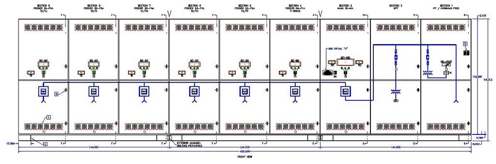
138 METAL-CLAD SWITCHGEAR Model SMCG, 38kV Example: Sections shown from left to right: Figure 7: 38kV, A - Blank Space / B A Breaker Section. Figure 7: 38kV, A - Blank Space / B A Breaker Section. Figure 7: 38kV, A - Blank Space / B A Breaker Section. Figure 7: 38kV, A - Blank Space / B A Breaker Section. Figure 7: 38kV, A - Blank Space / B A Breaker Section. Figure 7: 38kV, A - Blank Space / B A Breaker Section. Figure 7: 38kV, A - Blank Space / B A Breaker Section. Figure 6: 38kV, A - Drawout CPT Fuse Drawer / B - CPT Section. Figure 5: 38kV, A - Drawout PT / B - Blank Space Section. Refer to section matrix for specific applications. For special configurations and sizes, consult factory

139 HYBRID SWITCHGEAR (METAL-CLAD & METAL ENCLOSED SWITCHGEAR) Model SMECG, 5-38kV 5kV, 60kV BIL 15kV, 95kV BIL 27kV, 125kV BIL 38kV, 150kV BIL SECTION #1 SECTION #2 SECTION #3 SECTION #4 SECTION #5 SECTION #6 SECTION #7 SECTION #8 FRONT VIEW Application: Around the country at industrial plants, hotels, shopping centers, universities, waste water treatment facilities, renewable energy sites and other similar large facilities; there usually is a need to distribute electrical power at medium voltage (5kV-38kV). In order to distribute this electrical power, it is typically cable connected (above or below ground) to a central switchgear unit (single section or multi-section lineup), fed by a main circuit from the local utility company. There are two types of switchgear applied today for switching and protection of medium voltage (5kV- 38kV) power distribution systems. Metal-Clad Switchgear: Containing drawout circuit breakers and relays for both load switching and fault protection Metal-Enclosed Switchgear: Containing interrupter switches for load switching and power fuses for fault protection These two types of switchgear are defined in ANSI Standards (IEEE Std. C for METAL-CLAD) and (IEEE Std. C for METAL-ENCLOSED) The criteria for selecting one of these two types of switchgear units should be system complexity, cost, life cycle, protection & safety, and ease of operation. HYBRID SWITCHGEAR: The combination of both METAL-CLAD and METAL-ENCLOSED SWITCHGEAR for both load switching and fault protection. When high continuous currents are present and when either utility metering and/or smaller current distribution feeds are required, then HYBRID SWITCHGEAR would be the best possible choice for your system
140 HYBRID SWITCHGEAR (METAL-CLAD & METAL ENCLOSED SWITCHGEAR) Model SMECG, 5-38kV 5kV, 60kV BIL 15kV, 95kV BIL 27kV, 125kV BIL 38kV, 150kV BIL FOR RATINGS, ENCLOSURE TYPES, CONSTRUCTION FEATURES, FIGURE NUMBERS, OPTIONS AND STANDARD DIMENSIONS REFER TO THE METAL-ENCLOSED CATALOG SECTION 6.1 AND THE METAL-CLAD CATALOG SECTION 6.2 Multi-Section Lineup Section Matrix: Example on page Section #1 Section #2 Section #3 Section #4 Section #5 Section #6 Section #7 Section #8 Section #9 Section #10 Enter applicable METAL-CLAD FIGURE number: Enter applicable METAL-ENCLOSED FIGURE number: Switch ( Amps) For Each Section Switch-Fault Interrupt Rating ( ka) For Each Section Fuse ( Amps) For Each Section Fuse-Fault Interrupt Rating ( ka) For Each Section LINEUP DESCRIPTION: 6.3.2
141 HYBRID SWITCHGEAR (METAL-CLAD & METAL ENCLOSED SWITCHGEAR) Model SMECG, 5-38kV 5kV, 60kV BIL 15kV, 95kV BIL 27kV, 125kV BIL 38kV, 150kV BIL Section Matrix Example: Section #1 Section #2 Section #3 Section #4 Section #5 Section #6 Section #7 Section #8 Section #9 Section #10 Enter applicable METAL-CLAD FIGURE number: Enter applicable METAL-ENCLOSED FIGURE number: Switch ( Amps) For Each Section N/A N/A N/A Switch-Fault Interrupt Rating ( ka) For Each Section N/A N/A N/A Fuse ( Amps) For Each Section N/A N/A N/A Fuse-Fault Interrupt Rating ( ka) For Each Section N/A N/A N/A 10,000 10,000 10,000 LINEUP DESCRIPTION: 6-Section, Outdoor, NEMA 3R, 38kV, 1200A Hybrid Switchgear Lineup Includes Section 1 Incoming Bus Termination Section 2 Control Power Transformer Section 3 Main Breaker Section 4 Distribution Fused Switch (Front and Rear Aligned) (Depth Allows For Connection To Main Breaker) Section 5 Distribution Fused Switch (Front and Rear Aligned) Section 6 Distribution Fused Switch (Front and Rear Aligned) 6.3.3
142 HYBRID SWITCHGEAR (METAL-CLAD & METAL ENCLOSED SWITCHGEAR) Model SMECG, 38kV Example: Sections shown from left to right: Section 1: SMEG (Figure 4): 38kV, Entrance Section - Top Feed with Top-hat. Section 2: SMEG (Figure 9): 38kV, Metering Section. Section 3: SMEG (Figure 2): 38kV, Transition Section. Section 4: SMCG (Figure 7): 38kV, Breaker Section. Section 5: SMCG (Figure 7): 38kV, Breaker Section. Refer to section matrix for specific applications. For special configurations and sizes, consult factory
143 HYBRID SWITCHGEAR (METAL-CLAD & METAL ENCLOSED SWITCHGEAR) Model SMECG, 15kV Example: FRONT VIEW RIGHT SIDE VIEW SECTION A--A SECTION B--B Unit shown on this page and the next page is an outdoor Hybrid Switchgear Lineup. Sections shown from left to right: Section 1: SMCG (Figure 10): 15kV, Breaker Section w/pt s & Roof Bushings. Section 2: SMEG (Figure 7): 15kV, Distribution Section, Non-Fused Switch w/ct s. Section 3: SMEG (Figure 7): 15kV, Distribution Section, Non-Fused Switch w/ct s. Refer to section matrix for specific applications. For special configurations and sizes, consult factory
144 HYBRID SWITCHGEAR (METAL-CLAD & METAL ENCLOSED SWITCHGEAR) Model SMECG, 15kV Example: SECTION C--C SECTION D--D SECTION E--E SECTION F--F Unit shown on this page and the previous page is an outdoor Hybrid Switchgear Lineup. Sections shown from left to right: Section 1: SMCG (Figure 10): 15kV, Breaker Section w/pt s & Roof Bushings. Section 2: SMEG (Figure 7): 15kV, Distribution Section, Non-Fused Switch w/ct s. Section 3: SMEG (Figure 7): 15kV, Distribution Section, Non-Fused Switch w/ct s. Refer to section matrix for specific applications. For special configurations and sizes, consult factory

145 PARALLELING SWITCHGEAR Model LVPS V, 4000A Max. Model MVPS 5-15kV, 3000A Max Application: Powergrid Solutions Inc. custom designs and builds switchgear and controls for prime power, cogeneration, peak shaving, stand-by power and parallel operations for many markets. System Applications: Emergency/Standby Power Prime Power Base Load (Peak Shave) Import/Export Mode (Peak Shave) Isolate (Interruptible Rate) Cogeneration Markets Served: Airports Casinos, Hotels, and Resorts Data Centers Government Institutions Hospitals Manufacturing Facilities Military Mining Water & Wastewater Treatment Facilities Municipal Power Oil Platforms Oil Fields Pipeline Power Renewable Energy Schools / Universities Telecommunications Utilities 6.4.1


 touch screen w/alarms Communications")

146 PARALLELING SWITCHGEAR Model LVPS / Model MVPS Features Paralleling Switchgear Standard Features: Manual and automatic synchronizing and paralleling controls Sophisticated communications capabilities Remote diagnostics for convenience Remote system monitoring and control Ethernet switch and LAN modem to interface the Master PLC to HMI HMI (Human Machine Interface) touch screen w/alarms Communications connectivity to Building Management System Manual and automatic load demand control Best DC source selector system Power from 24VDC engine cranking batteries 6.4.2
147 PARALLELING SWITCHGEAR Model LVPS V, 4000A Max. Model MVPS 5-15kV, 3000A Max Powergrid Solutions Inc. Key Advantages Include: Customized solutions based on your needs Extensive experience with many utility company interconnect requirements Experience with multiple brands of engine-generators (Caterpillar, Cummins, Detroit Diesel, Jenbacher, Solar, Waukesha and more) Experience with multiple OEM brands of circuit breakers (drawout or fixed mounted) (ABB, Cutler-Hammer, GE, Siemens, Square D and more) Experience with multiple OEM brands of programmable logic controllers (PLC s) (Allen-Bradley, GE Fanuc, Siemens, Square D and more) Experience with multiple OEM brands of protective relays (Beckwith, Cutler-Hammer, GE Multilin, Schweitzer, Siemens and more) Switchgear Standard Offering Includes: Low voltage switchgear: Metal-enclosed design 480V and 600V ratings 60 hz, 3 phase, 3 or 4 wire Current rating of 1200, 2000, 3000 and 4000 amperes UL 891 listing - optional Service entrance rated and labeled Medium voltage switchgear: Metal-clad and/or metal-enclosed design 5kV and/or 15kV ratings Interrupting ratings of 250, 350, 500, 750 and 1000MVA Current rating of 1200, 2000 and 3000 amperes UL and NRTL listing - optional All switchgear is built to meet the applicable requirements of ANSI, IEEE and NEMA standards NEMA 1 indoor, NEMA 3R outdoor non-walk-in, or NEMA 3R outdoor walk-in sheltered aisle Mild steel, galvanneal steel or stainless steel with all-welded construction Paint finish: ANSI 61, ANSI 70 or customer preference Silver-plated or tin-plated copper bus Engine-Generator Control Include: Engine-generator of your choice Automatic engine start Adjustable engine cool down timer Engine governor control, load sharing, soft loading/unloading Generator phase and voltage matching synch Voltage regulator control VAR/PF sharing Automatic / manual paralleling Dead bus closing Import/export control 6.4.3
 Touch Screen Include: 12 inch color TFT display size Master Control Section Real time clock HMI Screens- Includes: Main Menu Screen with a")
148 PARALLELING SWITCHGEAR Model LVPS V, 4000A Max. Model MVPS 5-15kV, 3000A Max HMI (Human Machine Interface) Touch Screen Include: 12 inch color TFT display size Master Control Section Real time clock HMI Screens- Includes: Main Menu Screen with a complete listing of major screens System Overview Screen with a dynamic graphic display of the electrical one line System Control Screen System Metering Screen with graphical presentation of all functions System Settings Screen Generator Control Screen for each generator Generator Metering Screen for each generator with graphical presentation of all functions Generator Settings Screen Engine Monitoring (Engine Meter/Gauge) Screen for each generator Generator Engine Air / Cool Screen Generator Engine Oil / Fuel Screen Annunciator Menu Screen System Annunciation Screen Generator Annunciator Screen for each generator Report Menu Screen Password Entry screen that shall contain a numeric keypad for password entry Alarm Summary Screen that shall contain a time/date stamped System Alarm Summary System Trend Screen Generator Trending Screen Engine Historical Trending Screen 6.4.4

149 PARALLELING SWITCHGEAR Model LVPS V, 4000A Max. Model MVPS 5-15kV, 3000A Max Systems Communications Network: 6.4.5
150 PARALLELING SWITCHGEAR Model LVPS V, 4000A Max. Model MVPS 5-15kV, 3000A Max Factory Check Sheet Please fill out the Factory Check Sheet below along with providing Switchgear Specifications & One-line Drawings for a Request for Quotation. Today s Date Required Quote Date Customer Name Project Name Location Required On-Site Date LINEUP DESCRIPTION: 6.4.6

151 RELAY & CONTROL PANELS Model RCP Application: Around the country at utility, industrial and renewable energy applications, Relay & Control Panels provide protection, communications, automation and control. With real world experience in both traditional solutions as well as IEC based automation solutions, our engineers are at the cutting edge of IED engineering, design and integration. IEC was created to be an internationally standardized method of communication and integration and to support systems built from multivendor intelligent electronic devices (IEDs) that are networked to perform protection, monitoring, automation, metering, and control. Powergrid Solutions offers complete relay panel design, construction, fabrication, testing and installation. We procure, configure and integrate components from all the leading suppliers in accordance with your specifications, and offer not only standard rack mount panels but also full custom structures with swing-out panels. Our flexible manufacturing process allows our team to engineer and build relay panels to meet varied requirements, and customers needs
 Door stays (retained) hold doors in 90, 110 or 140 degree open positions Screened, tamper proof louvers Rear 3-point positive rotary latch mechanism, operated by a padlocking")
152 RELAY & CONTROL PANELS Model RCP Features Features: NEMA 1, NEMA 12 or NEMA 3R enclosures Standard 19-inch relay rack/s Hinged, removable lexan front barrier for protection against inadvertent contact (optional) Door stays (retained) hold doors in 90, 110 or 140 degree open positions Screened, tamper proof louvers Rear 3-point positive rotary latch mechanism, operated by a padlocking handle RELAY & CONTROL PANELS Relay & Control Panels for Switchgear Pilot Marshalling Cabinets Annunciator Panels Generator Control Panels Interposing Relay Panels Synchronizing Panels 6.5.2


153 RELAY & CONTROL PANELS Model RCP Examples: 6.5.3
154 RELAY & CONTROL PANELS Model RCP Factory Check Sheet Please fill out the Factory Check Sheet below along with providing Switchgear Specifications & One-line Drawings for a Request for Quotation. Today s Date Required Quote Date Customer Name Project Name Location Required On-Site Date DESCRIPTION: 6.5.4

155 LOW VOLTAGE SWITCHGEAR Model LVSG V, 4000A Max. Application: Around the country at industrial plants, hotels, shopping centers, universities, waste water treatment facilities, renewable energy sites and other similar facilities; there usually is a need to distribute electrical power at low voltage ( V). In order to distribute this electrical power, it is typically cable connected (above or below ground). Powergrid Solutions offers complete low voltage switchgear design, construction, fabrication, testing and installation. We procure, configure and integrate components from all the leading suppliers in accordance with your specifications, and can offer not only standard low voltage switchgear but also complete custom designs with controls and communication. Our flexible manufacturing process allows our team to engineer and build low voltage switchgear to meet varied requirements, and customers needs
 (ABB, Cutler-Hammer, GE, Siemens, Square D and more) 480V and 600V ratings 60hz, 3")
156 LOW VOLTAGE SWITCHGEAR Model LVSG V, 4000A Max. Features Features: Experience with multiple OEM brands of circuit breakers (drawout or fixed mounted) (ABB, Cutler-Hammer, GE, Siemens, Square D and more) 480V and 600V ratings 60hz, 3 phase, 3 or 4 wire Current rating of 1200, 2000, 3000 and 4000 amperes Service entrance rated and labeled UL 891 listing - optional 6.6.2

157 LOW VOLTAGE SWITCHGEAR Model LVSG Example: 6.6.3
158 LOW VOLTAGE SWITCHGEAR Model LVSG Factory Check Sheet Please fill out the Factory Check Sheet below along with providing Switchgear Specifications & One-line Drawings for a Request for Quotation. Today s Date Required Quote Date Customer Name Project Name Location Required On-Site Date DESCRIPTION: 6.6.4
159 FLEXAISLE (SHELTERED AISLE) Option for Models SMCG, SMEG, SMECG, LVPS, MVPS, RCP & LVSG Application: Our FlexAisle (FA) product also known as Electrical Equipment Center (EEC), Power Distribution Center (PDC), Power Equipment Center (PEC) or E-House; are intended for use with our models SMEG, SMCG, SMECG, RCP, LVSG, LVPS & MVPS. These prefabricated, self-contained steel structures typically safeguard low and medium voltage electrical equipment. In our FlexAisle (FA) construction the switchgear assembly may be designed as an integral part of the outdoor housing with welded construction for maximum structural reliability. Our FlexAisle (FA) has the flexibility to offer work areas, battery areas, and/or control rooms of different sizes that are integrated with the switchgear to meet specific customer needs and requirements. Along with the switchgear, typical equipment enclosed by a FlexAisle (FA) might include: Battery Systems, AC Panelboards, DC Panelboards, Automatic Transfer Switches, Control Panels, Relay Panels, Motor Control Centers, DSC, PLC, UPS and SCADA Systems. FlexAisles (FA) are designed to offer not only protection of the switchgear but also offers protection for personnel from a variety of environmental conditions. FlexAisle s are available in a variety of configurations including single aisle and common aisle construction utilizing mild steel or stainless steel which meet a wide variety of applications. These applications include Industrial Facilities, LFGTE Sites, Municipalities, Solar Farms, Utilities and Wind Farms to name a few
 HVAC")
160 FLEXAISLE (SHELTERED AISLE) Option for Models SMCG, SMEG, SMECG, LVPS, MVPS, RCP & LVSG Features Single-row Double-row Outdoor NEMA 3R construction Mild, galvanneal or stainless steel AWS weld certified Structural steel base Stainless steel hardware Special finishes and colors Personnel doors w/interior panic bars Integrated LV or MV switchgear Walls and roof insulation (optional) HVAC systems Lighting system Special cable or tray systems UPS systems DC power systems Stairs, rails or platforms Fireproofing walls (optional) Pressurization (optional) Fire suppression (optional) UL label (optional) PE approval (optional) 6.7.2


161 FLEXAISLE (SHELTERED AISLE) Option for Models SMCG, SMEG, SMECG, LVPS, MVPS, RCP & LVSG Features: 1. One (1) equipment door and one (1) personnel door provided with standard panic style exit bar. 2. Fluorescent light fixtures provide an average of approximately 50 foot-candles. 3. Internal wiring for lighting, AC control power and environmental controls in conduit, perimeter wireways and/or cable trays. 4. Lighted exit sign w/ emergency lighting installed above each door. 1. Base: Insulated or noninsulated. Undercoated for corrosion resistance. 5. Safety and security features includes but not limited to door alarms, battery alarms, gas detectors, smoke detectors, fire extinguishers, eyewash stations, occupancy sensors Floors: Non-skid finsh w/ choice of color. 3. Walls: Standard white with choice of color. 4. Cooling: Wall mounted units or combination units. 5. Heating: Space heaters, equipment heaters or combination units
162 FLEXAISLE (SHELTERED AISLE) Option for Models SMCG, SMEG, SMECG, LVPS, MVPS, RCP & LVSG Factory Check Sheet Exterior Overall Dimension: Height (H ) Width (W ) Depth (D ) Site Environmental Conditions: Outside Ambient Temperature Range: Low Deg. F High Deg. F Inside Ambient Temperature Range: Low Deg. F High Deg. F Maximum Wind Velocity: Less than 125 mph mph Roof Live Load: Less than 40 lbs/ft 2 lbs/ft 2 Classified Area: No Yes Class Division Group Corrosive Area: No Yes Describe: Environmental Control: Ventilation Only No Yes Air Conditioning No Yes Heating No Yes Paint Requirements: Interior Paint Color White Other Exterior Paint Color ANSI 61 Other Insulation Requirements: No Yes Doors R11 R19 Walls R11 R19 Ceiling R11 R19 Base R6.75 R11 R20 Miscellaneous Items / Options: Interior Fluorescent Lighting: No Yes Comments: Interior Incandescent Lighting: No Yes Comments: Convenience Receptacles: No Yes Comments: Exterior Lighting: No Yes Comments: Emergency Lighting: No Yes Comments: Exit Lights: No Yes Comments: Intrusion Alarm Device(s): No Yes Comments: Fire Detection Device(s): No Yes Comments: Fire Extinguisher(s): No Yes Comments: Station Battery System: No Yes VDC Comments: Circuit Breaker Lifting Device: No Yes Comments: Circuit Breaker Test Cabinet: No Yes Comments: Eye Wash Station: No Yes Comments: Space for SCADA Equipment: No Yes Comments: Space for Utility Supplied Equipment: No Yes Comments: Storage / Maintenance Area: No Yes Comments: Sheltered Aisle Control Power: Supplied by Others Supplied from the Switchgear 6.7.4

163 FLEXAISLE (SHELTERED AISLE) Option for Models SMCG, SMEG, SMECG, LVPS, MVPS, RCP & LVSG Example: This Flexaisle includes a metal-clad switchgear lineup which distributes electricity produced from the landfill-gas-to-energy renewable energy facility. The landfill gas generated will be used to produce renewable energy to be sold to a local utility under a long-term power purchase agreement. The power plant, which includes five turbine generators and a staff of four, is capable of generating enough renewable electricity to power nearly 25,000 homes
 Option for Models")

164 FLEXAISLE (SHELTERED AISLE) Option for Models SMCG, SMEG, SMECG, LVPS, MVPS, RCP & LVSG Example: 6.7.6
 hereby gives notice of its objection to any different or additional terms and conditions.")

165 TERMS and CONDITIONS The following conditions of sale shall govern the sale of any equipment, apparatus, process, services, or other product, hereafter referred to as product. Applicable Terms and Conditions Powergrid Solutions Inc (hereafter referred to as Powergrid Solutions) hereby gives notice of its objection to any different or additional terms and conditions. This sale is expressly conditional on Purchasers assent to the terms and conditions stated below. If not previously given, Purchasers acceptance of product is conclusive as to this assent. Unless different or additional terms and conditions are stated or referred to in the Powergrid Solutions proposal, in which even such different or additional terms and conditions shall be exclusive as to the particular subject covered, in the terms and conditions stated below apply. Such terms and conditions supersede any prior to contemporaneous agreements or correspondence between the parties. Quotations Each quotation is valid for 30 days from its date unless otherwise stated in the quotation. Prices Prices stated on the seller s acknowledgement for order, items or quantities thereon, for which the release for manufacturing is no longer than 90 days after customer r ceives final drawings, are not subject to upward or downward adjustments. Minimum order charge is $ USD. Taxes The price does not include any Federal, state or local property, license, privilege, sales, use, excise, gross receipts or other like taxes which may now or hereafter be applicable. Payment by Powergrid Solutions of any such taxes shall be for the account of the customer. Terms of Payment 1. Payment terms are Net 30 days from the date of the invoice. 2. If, in the judgment of Powergrid Solutions, the financial condition of Purchaser at any time prior to delivery does not justify the terms of payment specified, then Powergrid Solutions may require payment in advance or cancel any outstanding order, whereupon Powergrid Solutions shall be entitled to receive cancellation charges per Table A. If delivery is delayed by Purchaser, payment shall become due on the date Powergrid Solutions is prepared to make delivery. Delays in delivery or non-conformities in any installments shall not relieve Purchaser of its obligation to accept and pay for remaining installments. 3. If payments are not made when due, Purchaser shall pay, in addition to the overdue payment, a late charge equal to the lesser of 1.50% per month or the highest applicable rate allowed by law on all such overdue amounts. 4. Progress payments are not refundable unless agreed to in writing by Powergrid Solutions. Delivery Unless otherwise specified, all products are shipped F.O.B. point of shipment, regardless of transportation costs being allowed, prepaid or collect. Shipping Schedules Shipping dates are approximate and are based on receipt of complete information with the order. If drawing approval is required, drawings must be returned on schedule to maintain estimated shipping date. Change in shipping date due to vendor delays, production interruption or changes by the customer shall not hold Powergrid Solutions responsible for penalties, back charges or incurred cost. Drawing Approval and Changes Unless mutually agreed upon, Powergrid Solutions requires approval of submittal drawings. Such review, comment and/or approval must be received by Powergrid Solutions prior to commencing with manufacturing. Customer agrees to release for manufacturing all equipment no later than 60 days after receipt of final corrected drawings for approval. Purchaser s failure to comply with this requirement could result in delays in performance and increased costs. Where Purchaser s specifications are not sufficiently detailed, Powergrid Solutions reserves the right to design the product in line with, in Powergrid Solutions s judgment, good commercial practice. If, at any time, the Purchaser makes changes to the contract design as covered in the project specifications, the contract shall be subject to renegotiation of the price terms and delivery to reasonably cover any additional costs and commitments occasioned by the change. Shipment Damage Except in the event of F.O.B. destination shipments, Powergrid Solutions will not participate in any settlement of claims for concealed or other shipment damage. When shipment has been made on an F.O.B. destination basis, the Purchaser must unpack immediately and, if damaged is discovered, must: 1. Not move the product from the point of examination. 2. Retain shipping container and packing materials. 3. Notify the carrier of any apparent damage in writing on the carrier s delivery receipt and request the carrier to make an inspection. 4. Notify Powergrid Solutions within 72 hours of delivery. 5. Send Powergrid Solutions a copy of the carrier s inspection report. Force Majeure Powergrid Solutions shall not be liable for failure to perform or for delay in performance due to any cause beyond it s reasonable control, fire, flood, strike or other labor difficulty, act of God, natural disasters, act of governmental authority or of the Purchaser, riot, act of war, terrorism, vandalism, criminal activities by others, embargo, fuel or energy shortage, car shortage, faulty castings or forgings, wrecks or delay in transportation, or inability to obtain necessary labor, 7.1.1
Design Build Deliver. Metal Enclosed Switchgear, 5-35kV 1200 A Maximum Loadbreak, 4000 A Maximum Non-Loadbreak
 Metal Enclosed Switchgear, 5-35kV 1200 A Maximum Loadbreak, 4000 A Maximum Non-Loadbreak Powergrid Solution s Metal Enclosed Switchgear has many different customizable options and configurations. Customers
ME series dead-front fused sectionalizing enclosures MEC current limiting fusing and MEP power fusing 200 Amperes,15-25 kv
 ME series dead-front fused sectionalizing enclosures MEC current limiting fusing and MEP power fusing 200 Amperes,15-25 kv ABB ME series fused sectionalizing enclosures ABB's dead-front Padmount ME series
MDS Dead-front Padmount Switchgear Style Guide 1VAM SG May 2010 Revision D
 MDS Dead-front Padmount Switchgear Style Guide 1VAM224804-SG May 2010 Revision D The MDS style guide aids in the proper selection of your style number. When ordering the MDS, the style number must be given
TYPE PSI/II PADMOUNT SWITCHGEAR 15KV 25KV
 Cutler Hammer SECTION PB-1A-110 PAGE 1 Replaces April, 1996 TYPE PSI/II PADMOUNT SWITCHGEAR 15KV 25KV The PSI/II Padmount is the second generation of switchgear in the PSI switchgear family. The PSI/II
15-kV Wall-Mount Switchgear Three-Phase Indoor/Outdoor 600 Amp S&C Mini-Rupter Switch
 Page 1 2015 Kinked roof prevents standing moisture Glass reinforced barriers meet NEMA GPO-3 Standards 0.625" diameter copper ground bar Elliott air-insulated bushings accept IEEE Standard inserts and
35-kV Safefront SuperWell Mini-Switch Source Isolated Pad-Mounted Switchgear 50 Amp (Max) Clip-Mounted Current Limiting Fuses
 Clip-Mounted Current Limiting Fuses") Page 1 2016 EPMR-35-311S-R2/ESW-CM9 Three Phase Two Ways per Phase 200 Amp 35 kv Class Eaton s CPS LRTPs 50 Amp (Max) 27 kv Clip-Mounted NX Fuse Provisions 21.1/36.6 kv Grounded Wye Max Design, 150 kv
Page 1 2016 EPMR-35-311S-R2/ESW-CM9 Three Phase Two Ways per Phase 200 Amp 35 kv Class Eaton s CPS LRTPs 50 Amp (Max) 27 kv Clip-Mounted NX Fuse Provisions 21.1/36.6 kv Grounded Wye Max Design, 150 kv
SWITCHGEAR DIVISION PRODUCT PROFILES
 SWITCHGEAR DIVISION PRODUCT PROFILES Metal-Enclosed Load-Interrupter Switchgear Product Profiles Description: Three-Phase, Group-Operated Load-Interrupter Switches with Fuses in Single and Multi-Bay Assemblies
DEAD-FRONT PAD-MOUNTED SWITCHGEAR 15kV 25kV
 TYPE PSE MANUAL DEAD-FRONT PAD-MOUNTED SWITCHGEAR 15kV 25kV Figure 1 Federal Pacific Dead-Front PSE (available as UL Listed) contains an integrated system of fuses and switches with access control features
15-kV Live Terminal 600 Amp Group Operated Pad-Mounted Metal-Enclosed Outdoor Switchgear 140 Amp (Max) Clip Mount Current-Limiting Fuses
 Clip Mount Current-Limiting Fuses") Page 1 2015 Heavy duty 11-gauge steel enclosure is all-welded construction for long life Corrosion proof nameplate is located to provide easy access for the operator Glass reinforced barriers meet NEMA
Page 1 2015 Heavy duty 11-gauge steel enclosure is all-welded construction for long life Corrosion proof nameplate is located to provide easy access for the operator Glass reinforced barriers meet NEMA
Specification Pad-Mounted Capacitor Bank with Dual Fusing Integral Load-Interrupter on Line-Side Fuse Mountings
 Page 1 Specification Pad-Mounted Capacitor Bank with Dual Fusing Integral Load-Interrupter on Line-Side Fuse Mountings I. General This specification covers the design requirements for a pad-mounted capacitor
35-kV Safefront 200 Amp SuperWell Primary Capacitor Station Pad-Mounted Outdoor
 Page 1 2016 EPM-PCS-35-320P-R2/ESW-GCM6-2S-SA Three Phase Two Ways per Phase 200 Amp 35 kv Class Eaton's CPS LRTPs 35 kv Elliott Air-Insulated SuperWell Bushings 21.1/36.6 kv Grounded Wye Max Design, 150
ME Switchgear with Vacuum Circuit Breaker and Auto-jet II Switch with Ground Position
 LET S BE PACIFIC November 0 Volume Number 5 ME Switchgear with Vacuum Circuit Breaker and Auto-jet II Switch with Ground Position Federal Pacific has the capability to engineer, fabricate and assemble
35-kV Safefront 200 Amp SuperWell Primary Metering Station Pad-Mounted Outdoor
 35-kV Safefront 2 Amp SuperWell 5-33 Page 1 216 EPM-PMS-35-311P-R2/ESW Three Phase Two Ways per Phase 2 Amp 35 kv Class Eaton's CPS LRTPs NEMA Standard Outdoor Instrument Transformer Provisions 21.1/36.6
15-kV Safefront 200 Amp Primary Capacitor Station Pad-Mounted Outdoor
 Page 1 2015 Heavy-duty 11-gauge steel enclosure is all-welded construction for long life Clear polycarbonate removable safety barrier separates upper and lower compartment (supplied only with internally
STANDARD SPECIFICATION FOR TYPE PLD LIVE-FRONT/DEAD-FRONT PAD-MOUNTED SWITCHGEAR 15kV 25kV A. General
 Page 1 STANDARD SPECIFICATION FOR TYPE PLD LIVE-FRONT/DEAD-FRONT PAD-MOUNTED SWITCHGEAR 15kV 25kV A. General 1. Product The pad-mounted switchgear shall be in accordance with the applicable plans, drawings,
Underground Distribution Switchgear
 Underground Distribution Switchgear Functional Specification Guide Functional Specification for 15 kv, 25 kv, or 35 kv Underground Distribution Switchgear 1. Scope 1.1. This specification applies to three-phase,
SWITCHGEAR DIVISION PRODUCT PROFILES
 SWITCHGEAR DIVISION PRODUCT PROFILES Metal-Enclosed Load-Interrupter Switchgear Product Profiles Three-Phase, Group-Operated Load-Interrupter Switches with Fuses in Single and Multi-Bay Assemblies Manual,
Outdoor Padmount Switching Products
 Outdoor Padmount Switching Products Live-front & Dead-front 15 & 25 kv Switchgear, Fused Sectionalizing Enclosures, Metering and Capacitor Enclosures Rugged Outdoor Construction Safety and Security Features
S&C Manual PME Pad-Mounted Gear
 S&C Manual PME Pad-Mounted Gear Outdoor Distribution,. kv and 5 kv S&C Manual PME Pad-Mounted Gear... Featuring Elbow-Connected Encased Components. S&C Manual PME Pad-Mounted Gear brings in-air insulation,
Underground Distribution Switchgear
 Underground Distribution Switchgear Functional Specification Guide Functional Specification for 15 kv, 25 kv, or 35 kv Underground Distribution Switchgear 1. Scope 1.1. This specification applies to three-phase,
Michigan State University Construction Standards SECONDARY UNIT SUBSTATIONS PAGE
 PAGE 261116-1 SECTION 261116 PART 1 - GENERAL 1.1 RELATED DOCUMENTS A. Drawings and general provisions of the Contract, including General and Supplementary Conditions and Division 01 Specification Sections,
35-kV Safefront Mini-Switch Source Isolated Pad-Mounted Switchgear 50 Amp (Max) Clip-Mounted Current-Limiting Fuses
 Clip-Mounted Current-Limiting Fuses") Page 1 2016 Heavy duty 11-gauge steel enclosure is all-welded construction for long life 11-gauge steel equipment plate is rigid for easier elbow operation Parking stands for the upper two phases extend
Page 1 2016 Heavy duty 11-gauge steel enclosure is all-welded construction for long life 11-gauge steel equipment plate is rigid for easier elbow operation Parking stands for the upper two phases extend
STANDARD SPECIFICATION FOR PAD-MOUNTED CAPACITOR BANKS FOR 15kV or 25kV APPLICATIONS
 A. General 1. Product The pad-mounted capacitor banks shall be in accordance with the applicable plans, drawings, and one-line diagrams and shall conform to these specifications. 2. Assembly The outdoor
Switchgear Skid, C1192
 CUSTOM SOLUTIONS 15kV Modular Stairs stored on floor in front of battery bay Ground grid stored on front tongue of trailer Stairs deployed for unit access Storage box for fencing materials and other parts
C1000 Series Automatic Cap Bank
 C1000 Series Automatic Cap Bank Metal Enclosed - Medium Voltage Capacitors Assemblies Fixed / Auto Medium Voltage 5, 15, 25 and 35 kv Class Customized to your specifications The Reactive Power Solution
NEW Solutions for Underground System Growth
 NEW Solutions for Underground System Growth Cooper s Single-Phase Voltage Regulator Improved Power Quality More Economical Improved System Reliability Increased Safety Better Aesthetics Lower Maintenance
GENERAL INFORMATION POLE MOUNT TRANSFORMER SINGLE PHASE PAD MOUNT TRANSFORMER SINGLE PHASE POLE MOUNT TRANSFORMER THREE PHASE 17
 GENERAL INFORMATION SECTION GUIDE SECTION 10 PAGE 1 DESCRIPTION SECTION NUMBER GENERAL INFORMATION... 10 POLE MOUNT TRANSFORMER SINGLE PHASE... 15 PAD MOUNT TRANSFORMER SINGLE PHASE..... 16 POLE MOUNT
A. Three-phase, oil filled self-cooled, padmounted transformers are installed outdoors on pads in the EWEB distribution system.
 1. APPLICATION A. Three-phase, oil filled self-cooled, padmounted transformers are installed outdoors on pads in the EWEB distribution system. 2. REFERENCE STANDARDS A. The transformers supplied shall
15-kV Live Terminal 200 Amp Mini-Switch Source-Isolated Pad-Mounted Switchgear 40 Amp (Max) Arc-Strangler NX Fuses
 Arc-Strangler NX Fuses") Page 1 2015 Heavy duty 11-gauge steel enclosure is all-welded construction for long life Door safety barrier removal instructions Safety latches on the door safety barriers, front and rear, are insulating
Page 1 2015 Heavy duty 11-gauge steel enclosure is all-welded construction for long life Door safety barrier removal instructions Safety latches on the door safety barriers, front and rear, are insulating
SERIES 802 / 812 SPECIFICATION 15KV & 25KV PADMOUNTED LIQUID-INSULATED VACUUM LOAD INTERRUPTERS AND FUSE ASSEMBLIES
 SERIES 802 / 812 SPECIFICATION 15KV & 25KV PADMOUNTED LIQUID-INSULATED VACUUM LOAD INTERRUPTERS AND FUSE ASSEMBLIES MANUALLY OPERATED / REMOTELY OPERATED DEAD FRONT PADMOUNTED SWITCHGEAR WITH VACUUM LOAD
15-kV Safefront Mini-Switch Source Isolated Pad-Mounted Switchgear 140 Amp (Max) Clip-Mounted Current-Limiting Fuses
 Clip-Mounted Current-Limiting Fuses") Page 1 2016 Heavy duty 11-gauge steel enclosure is all-welded construction for long life 200 Amp Elliott air-insulated bushing wells accept IEEE Standard inserts and elbows ushing wells may be added or
Page 1 2016 Heavy duty 11-gauge steel enclosure is all-welded construction for long life 200 Amp Elliott air-insulated bushing wells accept IEEE Standard inserts and elbows ushing wells may be added or
2018 Consultant s Handbook Division 26 Electrical 2413 Switchboards
 1 General 1.1 Switchboards shall be U.L. listed and labeled. 1.2 Each switchboard shall have its own main disconnecting means unless it is located in the same room as its source of origin. In most cases
CABINET OPTIONS AND DESIGNATORS CODE LETTERS
 CABINET OPTIONS AND DESIGNATORS Hinges: ~Stainless steel lift off Nuts and Bolts: ~ Stainless steel Hardware: ~ Handles and Corbin locks are stainless steel or zinc plated Windows: ~ Lexan Backboards:
Figure 1. Single-phase pad-mounted voltage regulator. STANDARD FEATURES
 Voltage Regulators Single-Phase Pad-mounted Step GENERAL McGraw-Edison Single-Phase Padmounted Voltage Regulators add a dimension to underground system planning. They provide system planners freedom to
MEH Series Sectionalizing Enclosures. Single-Phase and Three-Phase
 MEH Series Sectionalizing Enclosures Single-Phase and Three-Phase ABB MEH Sectionalizing Enclosures ABB s MEH Sectionalizing Enclosures provide an economical and safe sectionalizing tap point for underground
Elastimold. Cable Accessories. Underground Distribution Switchgear. Molded Vacuum Switches and Fault Interrupters
 Underground Distribution Switchgear Molded Vacuum Switches and Fault Interrupters MVS Molded Vaccum Switches Spring-energy, load-switching devices that make, carry and interrupt load currents through 600
Solar Power Switchgear & Energy Storage Renewable Energy Systems
 7 Solar Power Switchgear & Energy Storage Renewable Energy Systems - Solution Brochure www.apt-power.com 433 N. 36 th Street PROVIDING A COMPREHENSIVE Lafayette, IN 47905 www.apt-power.com 433 APPROACH
CLARK PUBLIC UTILITIES TECHNICAL SPECIFICATIONS THREE-PHASE PADMOUNTED TRANSFORMERS
 CLARK PUBLIC UTILITIES TECHNICAL SPECIFICATIONS THREE-PHASE PADMOUNTED TRANSFORMERS Originated 1/85 Revised 6/95 Revised 6/02 Revised 11/05 Revised 4/08 Revised 11/09 Revised 1/12 Revised 11/12 Revised
DESIGN GUIDELINES LOW VOLTAGE SWITCHGEAR PAGE 1 of 5
 DESIGN GUIDELINES LOW VOLTAGE SWITCHGEAR PAGE 1 of 5 1.1. APPLICABLE PUBLICATIONS 1.1.1. Publications listed below (including amendments, addenda, revisions, supplements, and errata), form a part of this
Type MOST oil switch
 Underground Distribution witchgear CA285002EN Effective October 20 upersedes 285-20 October 2013 COOPER POWER ERIE ype MO oil switch Contents Description Page General...2 Ordering information....2 Features
CITY OF LOMPOC UTILITIES DEPARTMENT ELECTRICAL DIVISION SPECIFICATION NO. ELE-115
 CITY OF LOMPOC UTILITIES DEPARTMENT ELECTRICAL DIVISION SPECIFICATION NO. ELE-115 PADMOUNTED TRANSFORMERS 12kV AND DUAL VOLTAGE, RADIAL FEED STAINLESS STEEL NOVEMBER 2011 Specification:ELE_115_R1 Page
Solid Dielectric Load Break Switch SPECIFICATION. 25kV, 630A, 4 WAYS, 4 WAYS SWITCHED PADMOUNTED VACUUM LOAD INTERRUPTER
 Solid Dielectric Load Break Switch SPECIFICATION 25kV, 630A, 4 WAYS, 4 WAYS SWITCHED PADMOUNTED VACUUM LOAD INTERRUPTER MANUALLY OPERATED / REMOTELY OPERATED DEAD FRONT PADMOUNTED VACUUM LOAD INTERRUPTING
SPECIFICATION FOR THREE-PHASE PAD MOUNT TRANSFORMERS. D. Dead Front, loop feed design shall be employed.
 City of Cartersville Electric System P.O. Box 1390 320 S. Erwin St. Cartersville, GA 30120 770-387-5631 March 2006 SPECIFICATION FOR THREE-PHASE PAD MOUNT TRANSFORMERS This specification provides standardization
COMMERCIAL QUICK REFERENCE
 COMMERCIAL QUICK REFERENCE PROVO CITY POWER STANDARDS ELECTRICAL ENGINEERING UPDATED: 2016 SPECIFICATIONS SUBJECT TO CHANGE WITHOUT NOTIFICATION. 18" MIN. OF TAIL. (NEUTRAL CONDUCTOR MUST BE WHITE OR
Fixed, Medium-Voltage, Pad-Mounted, Three-Phase Power Capacitor Bank Guide Form Specification
 Fixed, Medium-Voltage, Pad-Mounted, Three-Phase Power Capacitor Bank Guide Form Specification 1. General 1.1 This specification is for a fixed, medium-voltage, padmounted, three-phase power capacitor bank
Single-phase pad-mounted step voltage regulator
 Voltage Regulators Catalog Data CA225002EN Supersedes February 2015 COOPER POWER SERIES Single-phase pad-mounted step voltage regulator General Eaton's Cooper Power series single-phase pad-mounted voltage
Automatic, Medium-Voltage, Pad-Mounted, Three-Phase Power Capacitor Bank Guide Form Specification
 Automatic, Medium-Voltage, Pad-Mounted, Three-Phase Power Capacitor Bank Guide Form Specification 1. General 1.1 This specification is for an automatic, medium-voltage, padmounted, three-phase power capacitor
AMENDMENT ELECTRIC SERVICE MANUAL 2014
 AMENDMENT (Pages 20,43,50,72,74,,76,78,83,86,99) ELECTRIC SERVICE MANUAL 2014 Effective April 1, 2015 18-7 6.0 SERVICE AND SERVICE ENTRANCES (General), Continued Conductor Sizing It is recommended that
PAD-MOUNT SWITCHGEAR 15kV 25kV 35kV
 PAGE 1 TYPE PSI PAD-MOUNT SWITCHGEAR 15kV 25kV 35kV INSTRUCTIONS For Installation and Operation INTRODUCTION... 1 Receiving... 1 Handling... 1 Storage... 1 GENERAL DESCRIPTION... 1 SAFETY FEATURES... 1
A. Submit manufacturer's literature and technical data before starting work.
 SECTION 16425 SWITCHBOARD PART 1 GENERAL 1.01 SUMMARY A. Related Section: 1. 16450 - Grounding. 1.02 SUBMITTALS A. Submit manufacturer's literature and technical data before starting work. B. Submit Shop
Specification Number: Product Name: GROUP MOUNTED MAIN FUSIBLE SWITCH, GROUP MOUNTED BRANCH FUSIBLE SWITCH (LONG) SECTION
 SECTION") Specification Number: 26 24 13.20 Product Name: GROUP MOUNTED MAIN FUSIBLE SWITCH, GROUP MOUNTED BRANCH FUSIBLE SWITCH (LONG) SECTION 26 24 13.20 SWITCHBOARDS (Long) Main Disconnect Group Mounted Fusible
Specification Number: 26 24 13.20 Product Name: GROUP MOUNTED MAIN FUSIBLE SWITCH, GROUP MOUNTED BRANCH FUSIBLE SWITCH (LONG) SECTION 26 24 13.20 SWITCHBOARDS (Long) Main Disconnect Group Mounted Fusible
UNDERGROUND SERVICES - SECONDARY
 UNDERGROUND SERVICES - SECONDARY Contents - Underground Services... U-1 General Requirements for Underground Service...U-2 Names of Parts for Underground Service... U-3 Service Termination in a Service
Guide Specification. Three-Phase Solid Dielectric Trident-SR with SafeVu Integral Visible Break
 Part 1-GENERAL 1.1 DESCRIPTION Guide Specification Three-Phase Solid Dielectric Trident-SR with SafeVu Integral Visible Break The switchgear shall consist of magnetically actuated solid dielectric insulated
University of Houston Master Construction Specifications Insert Project Name
 SECTION 26 13 13 MEDIUM VOLTAGE SWITCHGEAR PART 1 - GENERAL 1.1 RELATED DOCUMENTS: A. The Conditions of the Contract and applicable requirements of Divisions 0 and 1 and Section 26 00 01, Electrical General
STANDARD SPECIFICATION FOR LIVE-FRONT 15KV AND 25KV PSI/II PAD-MOUNTED SWITCHGEAR
 STANDARD SPECIFICATION FOR LIVE-FRONT 15KV AND 25KV PSI/II PAD-MOUNTED SWITCHGEAR A. General 1. Product The pad-mounted switchgear shall be PSI/II design as manufactured by Federal Pacific and shall conform
Descriptive bulletin. Medium voltage load interrupter switchgear Reliable, low maintenance and economical for distribution applications
 Descriptive bulletin Medium voltage load interrupter switchgear Reliable, low maintenance and economical for distribution applications General overview Reliable, low maintenance and economical Load Interrupter
Section SWITCHBOARDS. Introduction. Part 1 - General. Related Work
 Section 16435 - SWITCHBOARDS Introduction Part 1 - General Related Work Section 16070 Seismic Anchorage and Restraint Section 16075 Electrical Identification Section 16080 Power Distribution Acceptance
100 / 110 DRYWELL FUSE SPECIFICATION
 100 / 110 DRYWELL FUSE SPECIFICATION 15KV & 25KV SUBMERSIBLE VACUUM LOAD INTERRUPTERS AND DRYWELL FUSE ASSEMBLIES MANUALLY OPERATED / REMOTELY OPERATED SUBMERSIBLE SWITCHGEAR WITH LOAD INTERRUPTING SWITCHES
SECTION 27 - PAD-MOUNTED TRANSFORMERS TABLE OF CONTENTS
 CABLE AND CONDUIT ENTRANCE SINGLE-PHASE PAD-MOUNTED TRANSFORMER INSTALLATION 100 KVA AND LARGER (CONCRETE PADS ONLY) 27.05-01 CABLE AND CONDUIT ENTRANCE SINGLE-PHASE PAD-MOUNTED TRANSFORMER INSTALLATION
5kV to 38kV, 630 Amp to 4000 Amp Indoor or Outdoor Application
 The most advanced Arc-Resistant Switchgear, designed and built to provide maximum safety in the event of an Internal Arcing Fault. 5kV to 38kV, 630 Amp to 4000 Amp Indoor or Outdoor Application Page 1
MEDIUM VOLTAGE AIR INSULATED ARC-RESISTANT LOAD BREAK AND DISCONNECT SWITCHES
 MEDIUM VOLTAGE AIR INSULATED ARC-RESISTANT LOAD BREAK AND DISCONNECT SWITCHES Description JRS arc-resistant fused/non-fused load break and fused/non-fused disconnect switches are available for applications
Recreational Vehicle Park Electrical Products & Accessories
 Recreational Vehicle Park Electrical Products & Accessories 2 MILBANK OVERVIEW Milbank Overview Energy At Work since 1927 Milbank designs and manufactures electrical solutions that move and manage power
PAD-MOUNTED SWITCHGEAR INSPECTION & MAINTENANCE RECOMMENDATIONS TYPE PSI/II. 15kV 25kV. Qualified Persons
 Page 1 Qualified Persons... 1 Safety Information... 2 Procedures... 3 Maintenance... 3 Security Inspection (Exterior)... 3 Verify Securing Devices... 3 Maintaining the Exterior... 3 Replacing Labels...
CLARK PUBLIC UTILITIES TECHNICAL SPECIFICATIONS THREE-PHASE PADMOUNTED TRANSFORMERS
 CLARK PUBLIC UTILITIES TECHNICAL SPECIFICATIONS THREE-PHASE PADMOUNTED TRANSFORMERS Originated 1/85 Revised 6/95 Revised 6/02 Revised 11/05 Revised 4/08 Revised 11/09 Revised 1/12 Revised 11/12 Revised
A. This Section includes Low Voltage Switchgear Work, as indicated on the drawings, and as specified herein.
 16425 SWITCHBOARD ************************************************************************************************************* SPECIFIER: CSI MasterFormat 2004 number: 26 24 13 An optional keynote to
Three-Phase Pole Mounted Recloser
 Three-Phase Pole Mounted Recloser Page 1 of 8 Table of Contents 1 GENERAL... 3 2 CONSTRUCTION... 3-5 3 BUSHINGS... 5 4 LINE CONNECTOR... 5 5 TOOLS....5 6 NAMEPLATES..6 7 PAINT... 6 8 EXTERNAL HARDWARE
Low Voltage Switchgear Type WL Low Voltage Metal-Enclosed Switchgear
 13 Low Voltage Switchgear Siemens Type WL low voltage metal-enclosed switchgear is designed, constructed and tested to provide superior power distribution, power monitoring and control. At the heart of
Underground Distribution Switchgear
 Underground Distribution Switchgear Type VFI, Vacuum Fault Interrupter Switchgear Functional Specification Guide Functional Specification for 15 kv, 25 kv, or 35 kv Underground Distribution Switchgear
NX indoor current-limiting fuses
 Fusing Equipment Catalog Data CA132049EN Supersedes 240-60 September 2009 COOPER POWER SERIES NX indoor current-limiting fuses General Eaton provides overload protection for all indoor and underground
16.13 Unit Substation to 15kV Construction Standards Page 1 of 7
 Construction Standards Page 1 of 7.1 General.1 New buildings are to be provided with an indoor unit substation designed to accept 15kV and 25kV primary voltages, however, the primary voltage connected
25-kV Safefront Mini-Switch Phase Isolated Pad-Mounted Switchgear 125 Amp (Max) Clip-Mounted Current-Limiting Fuses
 Clip-Mounted Current-Limiting Fuses") ulletin Page 1 2018 11-gauge steel equipment plate is rigid for easier elbow operation Heavy-duty 11-gauge steel enclosure is all-welded construction for long life us and fuse schematic is orange-colored
ulletin Page 1 2018 11-gauge steel equipment plate is rigid for easier elbow operation Heavy-duty 11-gauge steel enclosure is all-welded construction for long life us and fuse schematic is orange-colored
Approved Contractor Construction e-guide Residential Commercial
 Approved Contractor Construction e-guide Residential Commercial Clark Public Utilities PO Box 8900 Vancouver, WA 98668 (PAGE 2) TABLE OF CONTENTS PAGE Trenching 3 Wire 8 Single-Phase Transformer Set 13
ELECTRIC SERVICE RULES DISTRIBUTED GENERATION Issued Jan 2016
 DISTRIBUTED GENERATION CHAPTER 5 500. SCOPE This chapter includes distributed or customer-owned generation connected in parallel and operating with Alliant Energy s electric distribution system. For all
Molded Current-Limiting Fuse
 Molded Current-Limiting provide fullrange fault current protection using specially designed fuse elements, rated through 23kV line to ground and 50kA interrupting current. Construction is modular with
10 Commercial, Industrial, Agricultural Services
 10 Commercial, Industrial, Agricultural Services This section describes the Power Company requirements for commercial, industrial, and agricultural services. This section covers single phase and three
GE 8000-Line Motor Control Centers
 GE 8000-Line -1 ENCLOSURE TYPES TYPE 1 General Purpose, Indoor Intended for use indoors, primarily to prevent accidental contact of personnel with the enclosed equipment, in areas where unusual service
TERMINATION ENCLOSURE OPTIONS
 TERMINATION ENCLOSURE OPTIONS Add suffix: R - Reverse Stagger the Bus Bars (to run cable in from the top) CU - Copper NEMA Mount Bus Bars C - Plastisol Covers for Bus Bars DF - Dead Fronts T - Tin Plated
35-kV Safefront 200 Amp Primary Metering Station Pad-Mounted Outdoor
 ulletin Page 1 2016 Heavy duty 11-gauge steel enclosure is all-welded construction for long life 11-gauge steel equipment plate is rigid for easier elbow operation Upper parking stands extend 3" per IEEE
Design Guide for Integration of Fixed-Mount Circuit Breakers
 Design Guide Design Guide for Integration of Fixed-Mount Circuit Breakers WL Low Voltage Power Circuit Breakers www.usa.siemens.com/wlbreaker Contents Introduction... 3 Mounting... 3 Mounting Surface...
15-kV Live Terminal Primary Metering Station Pad-Mounted Outdoor
 ulletin Page 1 2015 Cross-kinked roof prevents standing moisture Metering Transformer compartment label is visible with doors closed Heavy duty 11-gauge steel enclosure is all-welded construction for long
35-kV Apparatus Bushings B Series (bolt-in) for Elbow to Air-Insulated Service 200 Amp, 600 Amp, 900 Amp and 1250 Amp
 for Elbow to Air-Insulated Service 200 Amp, 600 Amp, 900 Amp and 1250 Amp") Page 1 2018 Grounded Metal Equipment Plate Equipment Connection Bus Bar or Other Component 35 kv Separable Insulated Connector (elbow) Grounded Metal Equipment Plate Equipment Connection Bus Bar or Other
Page 1 2018 Grounded Metal Equipment Plate Equipment Connection Bus Bar or Other Component 35 kv Separable Insulated Connector (elbow) Grounded Metal Equipment Plate Equipment Connection Bus Bar or Other
CON EDISON EQUIPMENT
 CON EDISON EQUIPMENT Con Ed Navtech Size Volts Amps List Spec. Cat. No Description Price 205 N-205 10x10x5 100 $72.00 205 RTN-205 10x10x5 100 190.00 215 N-215 24x12x8 200 144.00 215 RTN-215 24x12x8 200
CONTROLLIX CORPORATION CONTROLLIX.COM LOW VOLTAGE AUTOMATIC SWITCH CAPACITOR BANK SPECIFICATIONS
 LOW VOLTAGE AUTOMATIC SWITCH CAPACITOR BANK SPECIFICATIONS I. SCOPE a. This specification describes the necessary requirements for the design, fabrication, and operation of automatically switched, low
25 kv Apparatus Bushings
 Page 1 2001 ELRIM Cycloaliphatic Epoxy Provides: Nontracking, self-scouring, nonweathering performance Superior dielectric strength, dielectric loss and power factor Choice of shapes allows design innovation
Medium Voltage Metal-Enclosed Switches
 Medium Voltage Metal-Enclosed Switches Outdoor Medium Voltage Switch.1 Medium Voltage Switch MVS Product Description............................................. 2 Application Description..........................................
MATERIAL SPECIFICATION ELECTRIC OPERATIONS ORGANIZATION. M3902 ****Supercedes BECo Standard E and ComElectric Spec ****
 Page 1 of 8 ****Supercedes BECo Standard E2.12-2.12 and ComElectric Spec 6-0895**** 1.0 General Requirements SINGLE PHASE PAD-MOUNTED DISTRIBUTION TRANSFORMERS 1.1 These specifications cover single-phase
SafeGear TM Motor Control Center Arc resistant metal-clad construction
 SafeGear TM Motor Control Center Arc resistant metal-clad construction Contents Description 2 SafeGear TM MCC applications 3 Electrical features 3 Standards 3 Standard service conditions 4 HCV vacuum contactor
Metal-Enclosed Switches. Medium Voltage. Medium Voltage Metal-Enclosed Switches Contents
 January 2003 Vol. 1, Ref. No. [1011] -1 Medium Voltage Metal-Enclosed Switches Contents Description Page MVS................................... -2 and Breaker MSB........................ -3 Metal-Enclosed
25-kV Apparatus Bushings B Series (bolt-in) for Elbow to Air-Insulated Service 200 Amp, 600 Amp, 900 Amp and 1250 Amp
 for Elbow to Air-Insulated Service 200 Amp, 600 Amp, 900 Amp and 1250 Amp") Page 1 2018 Grounded Metal Equipment Plate Equipment Connection Bus Bar or Other Component 15 kv or 25 kv Separable Insulated Connector (elbow) Equipment Connection Power Cable Power Cable ELRIM Cycloaliphatic
Page 1 2018 Grounded Metal Equipment Plate Equipment Connection Bus Bar or Other Component 15 kv or 25 kv Separable Insulated Connector (elbow) Equipment Connection Power Cable Power Cable ELRIM Cycloaliphatic
15 kv and 25 kv Thru-Bushings
 Page 1 2001 ELRIM Cycloaliphatic Epoxy Provides: Nontracking, self-scouring, nonweathering performance Superior dielectric strength, dielectric loss and power factor Choice of shapes allows design innovation
MATERIAL STANDARD ELECTRIC OPERATIONS ORGANIZATION. ****Supercedes BECo Standard E and ComElectric Spec ****
 Page 1 of 8 ****Supercedes BECo Standard E2.12-2.14 and ComElectric Spec 7-0895**** THREE-PHASE DEADFRONT PAD-MOUNTED DISTRIBUTION TRANSFORMERS, LOOP & RADIAL FEED DESIGNS 1.0 General Requirements 1.1
35-kV 200-kV BIL Apparatus Bushings B Series (bolt-in) for Elbow to Air-Insulated Service 200 Amp, 600 Amp, 900 Amp and 1250 Amp
 for Elbow to Air-Insulated Service 200 Amp, 600 Amp, 900 Amp and 1250 Amp") Page 1 2018 Grounded Metal Equipment Plate Equipment Connection 35 kv Separable Insulated Connector (elbow) Bus Bar or Other Component Grounded Metal Equipment Plate Equipment Connection Bus Bar or Other
Page 1 2018 Grounded Metal Equipment Plate Equipment Connection 35 kv Separable Insulated Connector (elbow) Bus Bar or Other Component Grounded Metal Equipment Plate Equipment Connection Bus Bar or Other
35-kV Thru-Bushings F Series (bolt-in) for Air-Insulated to Air-Insulated Service 200 Amp, 600 Amp, 900 Amp and 1250 Amp
 for Air-Insulated to Air-Insulated Service 200 Amp, 600 Amp, 900 Amp and 1250 Amp") Page 1 2018 Equipment Connection Bus Bar, or Grounded Metal Equipment Plate F Series Mounting Holes ELRIM Cycloaliphatic Epoxy Provides: Nontracking, self-scouring, nonweathering performance Superior dielectric
Page 1 2018 Equipment Connection Bus Bar, or Grounded Metal Equipment Plate F Series Mounting Holes ELRIM Cycloaliphatic Epoxy Provides: Nontracking, self-scouring, nonweathering performance Superior dielectric
Outdoor Power Transmission & Distribution
 Description: The purpose of the section is to highlight the current applicable UMCP Design Standards and requirements for Outdoor Power Transmission and Distribution, including but not limited to the following:
SYSTEM PROTECTION SYSTEM PROTECTION. Underground Electric Distribution Standards I. FUSE COORDINATION
 I. FUSE COORDINATION I.1. GENERAL I.1.1. The purpose of protective coordination is to provide isolation of a fault as close to the fault as possible so that a minimum of customers will be affected. The
15-kV Safefront 200 Amp Primary Transformer Station Pad-Mounted Outdoor
 1-kV Safefront 200 mp ulletin 0-102 Page 1 2018 200 mp Elliott air-insulated bushing wells accept IEEE Standard inserts and elbows Open bottom and extra depth of elbow compartment provides space for use
15-kV Safefront 200 Amp Source Isolated Cable Switching Station Pad-Mounted Non-Fusible
 ulletin Page 208 -gauge steel equipment plate is rigid for easier elbow operation Heavy-duty -gauge steel enclosure is all-welded construction for long life "Elbows" compartment label is visible with doors
WARNING. TYPE PSI/II PAD-MOUNT SWITCHGEAR with Non-Loadbreak Fuse Mountings 15kV 25kV INSTRUCTIONS. Qualified Persons. For Installation and Operation
 PAGE 1 TYPE PSI/II PAD-MOUNT SWITCHGEAR with Non-Loadbreak Fuse Mountings 15kV 25kV QUALIFIED PERSONS...1 SAFETY INFORMATION...2 INTRODUCTION...3 Receiving...3 Handling...3 Storage...3 GENERAL DESCRIPTION...3
1500 kva Padmount Transformer delta Primary Voltage 208Y/120 Secondary Voltage
 1500 kva Padmount Transformer 12470 delta Primary Voltage 208Y/120 Secondary Voltage Cooper Power Systems Proposal Number: BED1096719 Date: January 4, 2010 Revision 00 Item Number: 00001 Item Details Customer
SECTION LOW VOLTAGE DISTRIBUTION EQUIPMENT
 SECTION 16400 LOW VOLTAGE DISTRIBUTION EQUIPMENT A. General 1. The University does not accept Series-Rated equipment for power distribution switchboards, distribution panels and branch circuit panelboards.