SWITCHGEAR DIVISION PRODUCT PROFILES
|
|
|
- Peregrine Wade
- 5 years ago
- Views:
Transcription


1 SWITCHGEAR DIVISION PRODUCT PROFILES Metal-Enclosed Load-Interrupter Switchgear Product Profiles Description: Three-Phase, Group-Operated Load-Interrupter Switches with Fuses in Single and Multi-Bay Assemblies Method of Operation: Manual, Automatic Source Transfer, SCADA Control, Shunt-Trip Circuit Configurations: Per Specification Applicable Standards: C , C , C37.57, C37.58 and C UL Listing at 5kV and 15kV, 600 to 1200 amperes Voltage Range: 5kV 35kV BIL: 60kV 200kV Ratings: 600 and 1200 ampere continuous 3-phase load-break switches Fusing to 1100 amps with current-limiting fuses Fusing to 720 amps with power fuses Switch 3-Phase 40ka asymmetrical 3-time fault-closing 61ka asymmetrical 1-time fault-closing 61ka momentary at 38kV 100 load-break operations at 600 amperes UL Recognized 600A, 1200A at 5kV and 15kV 1,000 mechanical operations Optional Features: Key Interlocks Stainless Steel Enclosure Copper Bus Special Colors Metering Requirements Monitoring Requirements Vacuum Circuit Breakers Category A, B and C Enclosures Close-Coupled to Transformer Stainless Steel Switches Users: Utility, Industrial, Military, Universities, Correctional, Hospitals, WWT Facilities Unit Substation Primary Switchgear Description: Method of Operation: Circuit Configurations: Applicable Standards: Voltage Range: BIL: Transformers: Current Ratings: Three-Phase, Group-Operated Load-Interrupter Switches with Fuses in Single and Multi-Bay Assemblies in Combination with Dry-Type Transformers Manual, Automatic Source Transfer, SCADA Control, Shunt-Trip Per Specification C , C , C37.57, C37.58 and C UL Listing at 5kV and 15kV, 600 to 1200 amperes, 1,000 mechanical operations 5kV 35kV 60kV 200kV Through 10MVA at 35kV to C and 1200 ampere continuous 3-phase load-break switches Fusing to 1100 amps with current-limiting fuses Fusing to 720 amps with power fuses Switch 3-Phase 40ka asymmetrical 3-time fault-closing 61ka asymmetrical 1-time fault-closing 61ka momentary at 38kV 100 load-break operations at 600 amperes UL Recognized 600A, 1200A, 5kV, 15kV 1,000 mechanical operations Optional Features: Key Interlocks Stainless Steel Enclosures Copper Bus Special Colors Copper Core & Coil Stainless Steel Switches Metering Requirements Monitoring Requirements Vacuum Circuit Breakers Category A, B and C Enclosures Users: Utility, Industrial, Military, Universities, Correctional, Hospitals, WWT Facilities 1

 600 and 1200 ampere continuous 3-phase load-break switches 200 ampere continuous 1-phase load-break with fuses Fusing to 200 amperes with current-limiting or")


2 Product Profiles SWITCHGEAR DIVISION PRODUCT PROFILES Air-Insulated Live-Front Type PSI/II Description: Method of Operation: Circuit Configurations: Applicable Standards: Voltage Range: Current Ratings: Three-Phase, Group-Operated Load-Interrupter Switches and Single- Pole, Hookstick Operated Fuses with Integral Load-Interrupters for Switching Manual, Automatic Source Transfer, SCADA Control, Shunt-Trip 25 one-line diagrams in 2, 4, 6 and 8 compartment designs C37.74 and C kV - 25kV (for 38kV consult factory) 600 and 1200 ampere continuous 3-phase load-break switches 200 ampere continuous 1-phase load-break with fuses Fusing to 200 amperes with current-limiting or power fuses Switch 3-Phase 40ka asymmetrical 3-time fault-closing 61ka asymmetrical 1-time fault-closing 100 load-break operations at 600 amperes UL Listed available to 600A at 15kV and 25kV 1000 mechanical operations Optional Features: Key Interlocks Surge Arresters Base Spacers Ground Studs Stainless Steel Enclosure Copper Bus Stainless Steel Switches Fuse Storage Cable Supports Inner Barrier Doors Special Colors Moisture Barriers Provisions for Fault Indicators Heaters Metering Transformers 1200 Amp Switches Designs Engineered to Customer Requirements Users: Utility, Industrial, Military, Universities, Correctional, Hospitals, WWT Facilities Air-Insulated Dead-Front Type PSE Description: Three-Phase, Group-Operated Load-Interrupter Switches with Single-Pole, Hookstick Operated Fuses with Bushing Wells for 200-Ampere Load-Break Elbows Method of Operation: Manual, Automatic Source Transfer, SCADA Control, Shunt-Trip Circuit Configurations: 20 one-line diagrams in 2, 4 and 6 compartment designs Applicable Standards: C37.74, C and ANSI 386 Voltage Range: 15kV 25kV Current Ratings: 600 ampere continuous 3-phase load-break switches 200 ampere continuous 1-phase load-break elbows Fusing to 200 amperes with current-limiting or power fuses Switch 3-Phase 40ka asymmetrical 3-time fault-closing 100 load-break operations at 600 amperes UL Listed available to 600A at 15kV and 25kV 1000 mechanical operations Optional Features: Key Interlocks Base Spacers Stainless Steel Enclosure Copper Bus Stainless Steel Switches Fuse Storage Cable Supports Special Colors Provisions for Fault Indicators 1200 Amp Switches Metering Transformers Designs engineered to customer requirements Users: Utility, Industrial, Military, Universities, Correctional, Hospitals, WWT Facilities 2

3 SWITCHGEAR DIVISION PRODUCT PROFILES Air-Insulated Dead-Front Vacuum Interrupter Type PVE Product Profiles Description: Method of Operation: Circuit Configurations: Applicable Standards: Voltage Range: Current Ratings: Three-Phase, Group-Operated Vacuum Interrupter and Three-Phase Group-Operated Vacuum Fault Interrupters. Manual, Automatic Source Transfer, Automatic Sectionalizing, Remote Operation, and SCADA Control. Multiple switching and protection arrangements in 2, 4 and 5 compartment designs. C37.74, C , C37.60, ANSI/IEEE kV and 25kV 600 amp continuous 3-phase load-break vacuum interrupters, with 1200 amp available at 15kV Three-time fault closing rating of 12,500 amps symmetrical / 20,000 amps asymmetrical. Rated for up to 10,000 load break operations at rated current. 600 amp continuous 3-phase vacuum fault interrupters, with 1200 amps available at 15kV Interrupting and fault close rating of up to 18,000 amps symmetrical / 28,800 amps asymmetrical at 15kV Interrupting and fault close rating of 12,500 amps symmetrical / 20,000 amps asymmetrical at 25kV. Compliant with fault interrupting duty specified in C Standard Features: Optional Features: Visible Disconnect on each Vacuum Interrupter Vacuum Interrupters 200 amp and 600 amp Resettable Vacuum Fault Interrupters 200 amp and 600 amp Overcurrent Protection with Self-Powered Relay or SEL Relay, on Vacuum Fault Interrupters Three-Phase Switching and Fault Protection Two-Way and Multi-Way Configurations External Manual or Motor Operators 200 Amp Bushing Wells 600 Amp Bushings Insulated Main Bus 11 Gauge Welded Steel Enclosure 1200 amp rating available at 15kV. Motor operators for SCADA or automatic transfer. Provisions for Fault Indicators Stainless Steel Key Interlocks Base Spacers Copper Bus Special Colors 200 Amp Bushing Wells Typical Users: Utilities, Industrial, Military, Universities, Correctional Hospitals, Water Plants 3


4 Product Profiles SWITCHGEAR DIVISION PRODUCT PROFILES Air-Insulated Live-Front / Dead-Front Type PLD Description: Three-Phase, Group-Operated Load-Interrupter Switches and Single-Pole, Hookstick Operated Fuses with Bushing Wells for 200-Ampere Load-Break Elbows Method of Operation: Circuit Configurations: Manual, Automatic Source Transfer, SCADA Control, Shunt-Trip A variety of one-line diagrams Applicable Standards: C37.74, C and ANSI 386 Voltage Range: Current Ratings: 15kV 600A and 1200A continuous 3-phase load-break switches 200 ampere continuous 1-phase load-break elbows Fusing to 200 amperes with current-limiting or power fuses Switch 3-Phase 40ka asymmetrical 3-time fault closing 61ka asymmetrical 1-time fault closing 100 load-break operations at 600 amperes UL Recognized 600A and 1200A 15kV switches 1000 mechanical operations Optional Features: Key Interlocks Stainless Steel Enclosure Stainless Steel Switches Special Colors Copper Bus Fuse Storage Base Spacers Cable Supports Provisions for Fault Indicators Designs engineered to customer requirements Users: Utility, Industrial, Military, Universities, Correctional Pad-Mounted Capacitor Banks Description: Three-phase capacitor bank with or without controller Single-Pole vacuum interrupters for switching current limiting fuses for fault protection Method of Operation: Manual or with Controller for Automatic Operation Applicable Standards: C , ANSI 386, Capacitors Switches to C37.66 Circuit Configurations: Per customer specification Voltage Range: 15kV and 25kV Current Ratings: 200 ampere continuous; 12,000 amperes rms symmetrical fault interrupting BIL: Capacitors: Switching Components: Protection Components: Control Power: 95,V and 125kV Size to 3600kvar as specified by customer Voltage as specified by customer Vacuum Capacitor Switch Current-Limiting Fuses selected by customer Reactors for in-rush restraint Voltage transformer Optional Features: Remote Control Kit Pad-Mounted Stainless Steel Enclosure Substation Mounting Surge Arresters Custom Relaying Integral Load Interrupterswith Emergency Switching to 800 kvar Designs engineered to customer requirements Users: Industrial, Government, Utility 4


5 SWITCHGEAR DIVISION PRODUCT PROFILES Product Profiles Fused Tap Dead-Front Type FTDF Description: Method of Operation: Circuit Configurations: Single-Phase and Three-Phase Fused Taps with and without Integral Single-Pole Load-Interrupters Combined with 200-Ampere Bushing Wells Manual, Single-Pole 8 Standard one-line diagrams and 8 designs Applicable Standards: C37.74, C and ANSI 386 Voltage Range: Current Ratings: Optional Features: 15kV 25kV 200 and 600 ampere continuous with 200-ampere, Single-phase integral load-break interrupters for switching with fuses 200 ampere continuous 1-phase load-break elbows Fusing to 200 amperes with current-limiting or power fuses Key Interlocks Stainless Steel Enclosure Special Colors Copper Bus Mimic Bus Dead-front access to fuses Users: Utility, Military, Universities, Correctional A single-phase FTDF model is pictured above. A typical three-phase FTDF Model is pictured above. 5


6 Product Profiles SWITCHGEAR DIVISION PRODUCT PROFILES Primary Metering Type PMDF Dead-Front and Type PMLF Live-Front Description: Method of Operation: Circuit Configurations: Three-Phase Primary Metering Compartments Type PMDF Accommodates Single-Pole Switching with Elbows Type PMLF Accommodates Conventional, Stress-Cone Terminators Per Specifications Applicable Standards: C37.74, C and ANSI 386 Voltage Range: 15kV 25kV Current Ratings: 200 ampere continuous 1-phase load-break elbows Optional Features: Stainless Steel Enclosure Copper Bus Special Colors 200 Ampere Bushing Wells 600 Ampere Bushings Mimic Bus Indoor and Outdoor Metering Transformers Designs engineered to customer requirements Users: Utility, Military, Universities, Correctional Wall-Mounted Fuses Description: Single-Phase and Three-Phase Fused Taps with and without Integral Single-Pole Load-Interrupters in a Wall-Mounted Enclosure Method of Operation: Manual, Single-Pole Circuit Configurations: Two Standard One-Line Diagrams and Custom Designs Applicable Standards: C37.74, C and ANSI 386 Voltage Range: 15kV 25kV Current Ratings: 200 ampere continuous 1-phase load-break elbows Fusing to 200 amperes with current-limiting or power fuses Optional Features: Stainless Steel Enclosure Special Colors 200 Ampere Bushing Wells Knockouts for conduit Users: Utility, Military, Universities, Correctional Wall-Mounted Switches Description: Three-Phase, Group-Operated Load-Interrupter Switches in a Wall-Mounted Enclosure Method of Operation: Manual, Automatic Source Transfer, SCADA Control, Shunt-Trip Circuit Configurations: One Standard One-Line Diagram and Custom Designs Applicable Standards: C37.74, C and ANSI 386 Voltage Range: 5kV 25kV Current Ratings: 600 Amperes Accommodates 600 Ampere Elbows 200 Amperes Accommodates 200 Ampere Load-break Elbows Switch 3-Phase 40ka asymmetrical 3-time fault-closing 61ka asymmetrical 1-time fault closing 100 load-break operations at 600 amperes UL Recognized 600A, 1200A, 5kV, 15kV 1000 mechanical operations Optional Features: Key Interlocks 600 Ampere Bushings Special Colors 200 Ampere Bushing Wells Stainless Steel Enclosure Copper Bus Stainless Steel Switches Motor Operators Remote Control Users: Utility, Military, Universities, Correctional 6
7 SWITCHGEAR DIVISION PRODUCT PROFILES Product Profiles Substations Description: Method of Operation: Three-phase portable substations for temporary, permanent or emergency power distribution application requirements integrating high-voltage, transformer and low-voltage sections Manual, Automatic Source Transfer, SCADA Control, Shunt-Trip Circuit Configurations: Engineered to customer requirements as a turn-key design Applicable Standards: C37.74, C , C , C37.57 and C37.58 Voltage Range: 4.16kV through 138kV high-voltage sections 120v, 240, 480, 600v secondary sections Current Ratings: 600 amperes and 1200 amperes BIL:` Based on system voltage requirements Tranformers: Dry-type through 10MVA at 38kV, Liquid-filled as customer specified Switching Components: Load-break Switches, Vacuum Circuit Breakers Protection Components: Fuses, Vacuum Circuit Breakers Optional Features: Skid Mounted Metering Requirements Trailer Mounted Monitoring Requirements Caterpillar Treads Relaying Requirements Rail Wheels Customer Specific Requirements Users: Utility, Industrial, Military, Correctional Facilities, WWT Facilities, Universities Distribution Vacuum Fault Interrupter Description: Three-phase vacuum fault interrupters for automatic reclosing on circuits to establish that fault is not permanent Method of Operation: Automatic tripping of vacuum circuit breakers Circuit Configurations: Per customer specification Applicable Standards: C37.60 Voltage Range: 15kV 25kV Current Ratings: 600 and 1200 amperes continuous; 12,000 amperes rms symmetrical fault interrupting. Also available: 15kV 1000A Continuous 20kA Interrupting 27kV 800A Continuous 16kA Interrupting BIL: 95kV to 125kV Transformers: Voltage Transformer for Control Power Switching Components: Vacuum Circuit Breakers Protection Components: Vacuum Circuit Breakers Optional Features: Various Trip Settings Remote Control Kit Pad-Mounted Stainless Steel Enclosure Substation Mounting Surge Arresters Visible Disconnect Users: Industrial, Government, Utility 7


8 Product Profiles SWITCHGEAR DIVISION PRODUCT PROFILES Switchgear Components Description: Load-break interrupter switches; Fuse mountings; Insulators; Bushings and bushing wells; Micro-processor controls; Motor operators, Vacuum circuit breakers, etc. Method of Operation: Manual, Automatic Source Transfer, SCADA Control Circuit Configurations: Customer Specified Applicable Standards: C37.57, C37.58, C ; ANSI 386 Voltage Range: 4.16kV 38kV Current Ratings: 200, 600 and 1200 amperes BIL: 60kV through 200kV Switching Components: Auto-jet II Load-Interrupter Switches, Vacuum Load-Break Switches, Vacuum Circuit Breakers Protection Components: Vacuum Circuit Breakers, Current-Limiting Fuses, Power Fuses Optional Features: Per specification requirements Users: Original Equipment Manufacturers 8

9 Manual Live-Front TYPE PSI/II MANUAL LIVE-FRONT PAD-MOUNTED SWITCHGEAR 15kV 25kV The PSI/II is Federal Pacific's line of live-front pad-mounted switchgear (available as UL Listed) built to IEEE C37.74 requirements and features the fully tested and field proven Auto-jet load-interrupter switch for switching three-phase circuits and the integral load-interrupter for single-phase load-break operation with fuses. General 15kV and 25kV Class - both available as UL Listed Proven Auto-jet switching Ratings normally found only in metal-enclosed switchgear Meets IEEE C37.74 requirements including 3-time faultclosing on switches and fuse mountings Removable barriers using NEMA Class GPO-3 non-hygroscopic fiberglass reinforced polyester barriers 100% X-rayed cycloaliphatic epoxy insulators 11-gauge pickled-and-oiled steel, all welded construction Meets ANSI C cabinet security and enclosure finish requirements Stainless-steel door-handle covers and switch operating pockets Stainless-steel hinges and hinge pins Overlapping active-passive door system with 3-point auto-latch door mechanism, padlockable door handle and standard penta-head or optional hex-head security bolts Ventilation louvers not required, sufficient ventilation being attained through non-gasketed doors and roof Anti-condensation roof undercoating Positive Latch Indicator on fuse interrupters verifies fully latched condition PSI/II is designed to meet the switching and isolating requirements of electrical distribution systems with 15 pre-engineered switching configurations. There are UL Listed standard units available to cover almost every situation radial feed, loop feed and manual primary-selector switching. Special configurations and designs are available upon request. The three-time fault-close ratings, with the laboratory and field-proven Auto-jet system, can solve both your "near substation" high fault-current and mid-point loop switching applications as well as "distant end-point" standard fault-current requirements. 9
10 Applications PSI/II lends itself to meet distribution system requirements, whether it is a simple radial feed or a complex loop system. With 3-pole, group-operated load-interrupter switches, 3-phase sets of single-pole fuses and solid bus taps all available as UL Listed applications are almost unlimited. Manuarl Live-Front Radial Feed PSI/II provides isolation and fuse protection in radial systems. Radial systems are used where service reliability and load type do not warrant the increased investment of the more flexible loop system. The radial system is used where there are many lateral cables, each to serve a small number of dispersed loads. SIMPLE OPEN LOOP Z Z Loop Feed PSI/II provides sectionalizing in a loop feed distribution system. This system, with loop cable attached to the source at two points and a "normally open" switch near the load mid-point, provides excellent manual sectionalizing. The Auto-jet II switches are opened and closed as required to isolate a cable problem or faulted circuit condition and to provide complete service restoration. N. O. Primary Selector Switch PSI/II units are applied as primary selector switches to serve critical loads. This allows manual restoration of service upon the loss of the preferred source. 10


11 Features The basic switchgear enclosure has been designed to present the smallest possible profile commensurate with the generally accepted electrical clearances, operating procedures, component requirements and various methods of training and terminating underground distribution cable. These pad-mounted switchgear designs are UL Listed. Standard features include: heavy 11-gauge hot-rolled pickledand-oiled steel, all welded construction, stainless-steel hinges and switch operating pockets, active/passive compartment access doors with 3-point auto-latch door mechanisms, padlockable door handles and penta-head security bolts. These standard features, along with a rugged tamper-resistant design, provide a unit that meets the stringent security requirements of ANSI C Electrical integrity has been enhanced by the Auto-jet II switching system, NEMA Class GPO-3 barriers, 100% x-rayed cycloaliphatic epoxy insulators and a wide choice of both power and current-limiting fuses. High quality steel, corrosion-resistant hardware, chemical cleaning and phosphatizing or zirconization, corrosion resistant epoxy-powder primer and a baked polyesterpowder top-coat make the anti-corrosion coating system a leader in the industry. The standard finish color is pad-mount green, Munsell 7GY3.29/1.5. Standard options let you select units that best serve your needs and operating practices. Options include: front barriers to meet either NESC or RUS specifications; base spacers to provide for increased cable terminating height; ground stirrups for convenient cable grounding; key interlocking for anti-paralleling and access control; and surge arresters. These are just a few of the many options listed on pages 18 and 19. Barriers Designing equipment to a minimum size consistent with electrical clearance requirements adds to the aesthetic qualities of padmounted switchgear. The use of interphase, phase-to-ground and dual-purpose front barriers enhance operation by field personnel. The dual-purpose barriers, in their normal hanging position, help prevent inadvertent contact with live parts. In addition, these barriers can be temporarily inserted into the open gap when the switch or fuse is open, but should not remain in this alternate position for more than one week. A removable, clear window panel above the switch dual-purpose barriers allows visual verification of the switch blade position with the barriers in their normal hanging position. A fixed metal panel is mounted above the dual-purpose barriers in the fuse compartments as a top barrier guide. Some barrier systems while highly desirable, restrict the space available for installing and terminating high-voltage cables entering the switch and fuse compartments. To eliminate this restriction, Federal Pacific's standard barrier system, in PSI/ II switch and fuse compartments, incorporates unique "removable" barriers which allow removal of interphase barriers during cable installation... without removal of any hardware. With the switchgear completely de-energized, removal of these barriers from a compartment facilitates cable installation, termination and repair. In order to get this same freedom during installation, other barrier systems require time consuming disassembly and reassembly. Manual Live-Front Switch-side removable interphase barriers facilitate cable installation and termination. Interphase barriers are not to be removed when switchgear is energized. Switch compartments (above) with dual-purpose barrier shown in normal hanging position on compartment at right and in alternate slide-in position on compartment at left. Barrier should not be left in alternate position for more than one week. Hinged B4 barrier shown on switch compartment at left. Fuse compartments (at right) shown with dual-purpose barriers in temporary storage position on door, in alternate slide-in position on center phase of left compartment (barriers should not be left in alternate position for more than one week) and in normal hanging position on right compartment. Fuse-compartment interphase barriers are removable without loosening hardware no tools required. Interphase barriers are NOT to be removed when switchgear is energized. Fuse-compartment dual-purpose barriers in normal hanging position. Hinged B4 barrier also shown. 11


12 Manuarl Live-Front Auto-Jet II Switch The unique feature of the Federal Pacific PSI/II Pad-Mounted Switchgear is the Auto-jet II 3-pole group-operated switch. The Auto-jet II switch provides 600 amperes continuous and load-break at 15kV and 25kV, and to 40,000 amperes RMS/ASYM momentary and 3-time fault-close capability. Switches rated 1200 amperes continuous and interrupting are also available. The Auto-jet II switch provides a unique method of load interruption, producing a laminated jet of air which extinguishes the arc. Auto-jet II switches are designed to provide a safe and convenient means for 3-pole switching of distribution transformers, cable loops and laterals, and to provide manual selection of preferred and alternate sources. All Auto-jet II switches have a heavy-gauge steel frame which assures proper contact alignment and eliminates any problem of switch-to-enclosure alignment. A quick-make, quick-break stored energy mechanism with heavy-duty, long-life die springs, provides high speed opening and closing independent of the operating handle speed. This high speed mechanism assures safe 3-time fault-closing capability and load interruption with the Autojet II interrupter. The switch blades are made of high conductivity copper. Current transfer from the switchblade through the hinge terminal is accomplished by a unique current transfer means, consisting of a silver-plated beryllium copper louvered contact band encircling a silver-plated copper heavy walled precision bushing at the hinge point. Due to higher than normal current flow, magnetic forces tend to rotate the louvers on the contact band toward a vertical position, providing a higher contact pressure for fault-current duty. Auto-Jet II Switch Ratings Nom. kv Max. Des. BIL * These are nominal switch ratings. Rating of integrated padmounted unit is determined by lowest rated component and may be limited by fuse ratings. Use fuse rating charts on pages 15 and 17 to select proper short circuit values. 2 Barriers installed. Max. Cont. Amperes, RMS 1 Interrupting Mom. & Fault- Max. Cable Close Mag. Load Chrg. (ASYM KA) Fault- Close Duty- Cycle 3 1-sec. (SYM KA) 3The 3-time fault-close duty-cycle rating means that the device can be closed three times into rated fault-current and remain operable and able to carry and interrupt its rated load-current. *1-time duty-cycle fault-closing rating is 61ka rms asymmetrical. Illustration of Auto-jet II Switch Interrupter 15-kV Auto-jet II Switch Switch closed with opening spring relaxed. Latch engaged to hold switch in position. Switch closed with opening spring charged by manual operating handle. Main contacts parted, puffer and arcing springs charged. Switch open with latch engaged to hold switch in position. 12
 Fuse Open Fuse Closed and Latched Positive Latch Indicator (fuse latched) Manual Live-Front Shown here are only two of the many fuses which can be used")
13 Auto-jet II Loadbreak Fuse Mountings Auto-jet for SM-4 Refill Unit Shown with SML-4Z Fuseholders Auto-jet for DBU, CMU or SMU-20 Fuse Unit Shown with DBU Fuse Assemblies Fuse Open Fuse Closed and Latched Positive Latch Indicator (fuse latched) Fuse Open Fuse Closed and Latched Positive Latch Indicator (fuse latched) Manual Live-Front Shown here are only two of the many fuses which can be used with the Auto-jet fuse mountings. See pages 11 and 13 for a more complete listing of fuses compatible with Auto-jet fuse mountings. The wide selection of fuse models available in PSI/II Pad- Mounted Switchgear provides maximum flexibility in the design and protection of underground distribution systems. Load-break Auto-jet fuse mountings accommodate S&C Types SM-4 and SMU-20, Eaton Type DBU, and Cooper Type CMU, NX and X-Limiter fuses in 15kV and 25kV class PSI/II units. The Positive-Latch Indicator (PLI) on Federal Pacific loadbreak fuse mountings is a reliable innovative semiphore target that shows when fuse assemblies are fully closed and latched, ready for a subsequent load-break opening operation. Illustration of Auto-jet EZ-Latch Fuse Interrupter Closed: Hookstick ready to open, latch properly engaged. See Positive Latch Indictor in photos at top of page. Main contacts parted, puffer spring charged, latch disengaged. Interrupter parted (internal). Holder parted, Auto-jet reset for next operation. The Auto-jet fuse mounting has a direct drive, integral load-break interrupter that permits single-pole live switching in single-phase or three-phase circuits by the use of an ordinary hotstick. The Auto-jet interrupter has a 3-time fault-close duty-cycle when the fuse is closed briskly without hesitation. The overall unit rating may be limited by the fuse rating. The same unique laminated air-jet interrupter used in the threepole group-operated switches is applied in the Auto-jet loadbreak fuse mountings. 13
14 15kV Basic Units-Three-Phase 14.4kV Nominal 17kV Maximum Design 95 kv BIL Circuit Diagrams with Compartment Numbers PSI/II Pad-mounted Switchgear is designed for use only by qualified personnel trained to operate medium voltage (2.4kV kV) switchgear. Users other than electric utilities are urged to use key interlocking devices as applicable. Should non-utility users elect not to use key interlocks, they must submit written certification that only qualified and trained personnel will operate the equipment, and that key interlock systems are not required. PSI/II-3 PSI/II-4 PSI/II /2" W x 44-1/2" D 35-1/2" W x 44-1/2" D 35-1/2" W x 58-1/2" D Manuarl Live-Front Models PSI/II-4 and PSI/II-15 are only available to electric utilities. All units are 51" high without base spacers. Do not use any dimensions for construction purposes. To determine complete catalog number for PSI/II models with fuse compartments substitute for "* " shown as last figure in the catalog number listed below each diagram on this page the number shown in the following table: 1 S&C Type SM-4 3 Not applicable 2 S&C Type SMU-20 5 Cooper (M-E) Type NX 2 Eaton DBU 7 Cooper (CT) X-Limiter 2 Cooper Type CMU Cat. No Cat. No. 4201* Cat. No. 4211* PSI/II-6 PSI/II-61 PSI/II-7 PSI/II-8 67" W x 58-1/2" D 67" W x 72" D 67" W x 58-1/2" D 67" W x 58-1/2" D Cat. No. 4321* Cat. No. 4431* Cat. No. 4312* Cat. No. 4412* PSI/II-9 PSI/II-10 PSI/II-11 PSI/II-12 67" W x 58-1/2" D 67" W x 58-1/2" D 67" W x 58-1/2" D 67" W x 58-1/2" D Cat. No. 4422* Cat. No Cat. No. 4431* Cat. No. 4413* PSI/II-13 PSI/II-131 PSI/II-14 PSI/II PSI/II-15 67" W x 58-1/2" D 67" W x 58-1/2" D 67" W x 58-1/2" D 67" W x 58-1/2" D Cat. No Cat. No Cat. No. 4421* Cat. No. 4403* 14
15 Current Ratings - 15kV Basic Units 15kV Basic Units Switch Only Units, PSI/II -3, -10, -13, -131 Continuous Current Load and Loop Switching Auto-jet II Switch Ratings - Amps RMS Short-Circuit Withstand Current 3-Time (Sym.) Fault-Close (Asym.) 14,000 22,400 36, * ,000 40,000 65, * 25,000 40,000 65,000 Three-time fault rating. The Auto-jet II switch can be closed into a fault of the magnitude specified three times and remain operable, and able to carry and to interrupt the rated current. Exceeds C37.74 rating requirements. *UL Listed equipment is available for 600A switchgear at both 14kA sym/22.4ka asym and 25kA sym/40ka asym. Peak Withstand Current Manual Live-Front Fuse Only & Switch/Fuse Units: PSI/II -4, -5, -6, -61, -7, -8, -9, -11, -12, -14, -15 Unit Overall Ratings Amperes RMS Fuse Ratings Short Circuit 3 Amperes RMS Fuse Manufacturer and Type 12 Momentary ASYM MVA 3-Phase at 14.4 kv SYM Max. Loadbreak 4 1 For fuse application and ordering information, refer to the applicable fuse manufacturer literature. Interrupting SYM 5 3-Time Fault-Close6 ASYM S&C SM-4 20, ,500 20,000 S&C SMU-20 22, ,000 22,400 S&C SM CONTACT FACTORY Eaton DBU 22, ,000 22,400 Cooper 8 CMU 22, ,000 22,400 Cooper (M-E) NX 40, ,000 40,000 Cooper (CT) X-Limiter 40, ,000 40,000 2 SM-4 fused units require three S&C Cat. No SML- 4Z fuseholders and three S&C SM-4 fuse refills per fuse compartment. SMU-20 fused units require three FP-3097 fuse-unit end fittings and any three of one of the following fuse units: S&C SMU-20, Eaton DBU or Cooper CMU, per fuse compartment. DBU fused units require three FP-3097 fuse-unit end fittings and any three of one of the following fuse units: S&C SMU- 20, Eaton DBU or Cooper CMU, per fuse compartment. CMU fused units require three FP-3097 fuse-unit end fittings and any three of one of the following fuse units: S&C SMU- 20, Eaton DBU or Cooper CMU, per fuse compartment. NX fused units require three sets of Auto-jet II end fittings (see table below) and three appropriately rated fuses per fuse compartment. NOTE: NX Clip Style non-loadbreak fuse mountings are available and will accommodate up to 200 ampere NX fuses. X-Limiter fused units require three sets of Auto-jet II end fittings (see table below) and three appropriately rated fuses per fuse compartment. X-Limiter end fittings suitable for installation of complete fuse assemblies in SML-20 Power Fuse Mountings are also available. Consult factory for availability. Fuse kv Fuse Amperes Mtg. Code End Fittings Catalog No # # Includes a code 5 to code 4 adapter 3 Unit overall ratings are limited to the lowest component rating. 4 Load-break rating same as maximum continuous current rating. 5 Ratings expressed in RMS amperes asymmetrical are 1.6 times the symmetrical values listed. 6 Three-time fault-close rating: The Auto-jet II fuse mounting can withstand a fuseholder or fuse with end fitting being closed into a fault of the magnitude specified three times when closed briskly without hesitation and remain operable and able to carry and interrupt the rated continuous current. The fuse must be replaced following a fault-closing. Refer to S&C instruction manual for SML-4Z holder and SML-20 end fitting maintenance required after each fault-close or fault interruption. 7 Contact the factory for SM-5 applications. 8 These fuses are not available in UL Listed models. 15
16 25kV Basic Units-Three-Phase 25kV Nominal 29kV Maximum Design 125 kv BIL Circuit Diagrams with Compartment Numbers PSI/II Pad-mounted Switchgear is designed for use only by qualified personnel trained to operate medium voltage (2.4kV kV) switchgear. Users other than electric utilities are urged to use key interlocking devices as applicable. Should non-utility users elect not to use key interlocks, they must submit written certification that only qualified and trained personnel will operate the equipment, and that key interlock systems are not required. PSI/II-3 PSI/II-4 PSI/II-5 43" W x 54-1/2" D 43" W x 54-1/2" D 43" W x 74-1/2" D Manuarl Live-Front Models PSI/II-4 and PSI/II-15 are only available to electric utilities. All units are 61" high without base spacers. Do not use any dimensions for construction purposes. To determine complete catalog number for PSI/II models with fuse compartments substitute for "* " shown as last figure in catalog number listed below each diagram on this page the number shown in the following table: 1 S&C Type SM-4 3 Not applicable 2 S&C Type SMU-20 5 Cooper (M-E) Type NX 2 Eaton DBU 7 Cooper (CT) X-Limiter 2 Cooper Type CMU Cat. No Cat. No. 5201* Cat. No. 5211* PSI/II-6 PSI/II-61 PSI/II-7 PSI/II-8 82" W x 74-1/2" D 82" W x 90" D 82" W x 74-1/2" D 82" W x 74-1/2" D Cat. No. 5321* Cat. No. 5431* Cat. No. 5312* Cat. No. 5412* PSI/II-9 PSI/II-10 PSI/II-11 PSI/II-12 82" W x 74-1/2" D 82" W x 74-1/2" D 82" W x 74-1/2" D 82" W x 74-1/2" D Cat. No. 5422* Cat. No Cat. No. 5431* Cat. No. 5413* PSI/II-13 PSI/II-131 PSI/II-14 PSI/II-15 82" W x 74-1/2" D 82" W x 74-1/2" D 82" W x 74-1/2" D 82" W x 74-1/2" D Cat. No Cat. No Cat. No. 5421* Cat. No. 2763* 16
17 Current Ratings - 25kV Basic Units 25kV Basic Units Switch Only Units, PSI/II -3, -10, -13, -131 Auto-jet II Switch Ratings - Amps RMS Short-Circuit Withstand Current Continuous Load and Loop 3-Time Current Switching (Sym.) Fault-Close (Asym.) ,500 20,000 32,500 25,000* 40,000* 65,000 *UL Listed equipment is available at 25kA sym./40ka asym. Fuse Only & Switch/Fuse Units: PSI/II -4, -5, -6, -61, -7, -8, -9, -11, -12, -14, -15 Unit Overall Ratings Amperes RMS Fuse Ratings Short Circuit 3 Amperes RMS Fuse Manufacturer and Type 1 2 Momentary ASYM MVA 3-Phase at 14.4 kv SYM Peak Withstand Current S&C SMU-20 20, ,500 20,000 S&C SM CONTACT FACTORY Eaton DBU 20, ,500 20,000 Cooper 8 CMU 20, ,500 20,000 Cooper (M-E) NX 40,000 1, ,000 40,000 Cooper (CT) X-Limiter 40,000 1, ,000 40,000 Applicable to solidly-grounded-neutral systems only with fuses connected by single-conductor, concentric-neutral type cable to a transformer or transformers. Rating is 9,400 amperes RMS symmetrical, 15,040 amperes RMS asymmetrical (405 MVA) for all other applications. Max. Loadbreak 1 For fuse application and ordering information, refer to the applicable fuse manufacturer literature. Interrupting SYM 5 3-Time Fault-Close6 ASYM S&C SM-4 20, ,500 20,000 Manual Live-Front 2 SM-4 fused units require three S&C Cat. No SML- 4Z fuseholders and three S&C SM-4 fuse refills per fuse compartment. SMU-20 fused units require three FP-3097 fuse-unit end fittings and any three of one of the following fuse units: S&C SMU-20, Eaton DBU or Cooper CMU, per fuse compartment. DBU fused units require three FP-3097 fuse-unit end fittings and any three of one of the following fuse units: S&C SMU- 20, Eaton DBU or Cooper CMU, per fuse compartment. CMU fused units require three FP-3097 fuse-unit end fittings and any three of one of the following fuse units: S&C SMU- 20, Eaton DBU or Cooper CMU, per fuse compartment. NX fused units require three sets of Auto-jet II end fittings (see table below) and three appropriately rated fuses per fuse compartment. X-Limiter fused units require three sets of Auto-jet II end fittings (see table below) and three appropriately rated fuses per fuse compartment. X-Limiter end fittings suitable for installation of complete fuse assemblies in SML-20 Power Fuse Mountings are also available. Consult factory for availability. Fuse kv Fuse Amperes Mtg. Code End Fittings Catalog No # # Includes a code 6 to code 5 adapter. 3 Unit overall ratings are limited to the lowest component rating. 4 Load-break rating same as maximum continuous current rating. 5 Ratings expressed in RMS amperes asymmetrical are 1.6 times the symmetrical values listed. 6 Three-time fault-close rating: The Auto-jet II fuse mounting can withstand a fuseholder or fuse with end fitting being closed into a fault of the magnitude specified three times when closed briskly without hesitation and remain operable and able to carry and interrupt the rated continuous current. The fuse must be replaced following a fault-closing. Refer to S&C instruction manual for SML-4Z holder and SML-20 end fitting maintenance required after each fault-close or fault interruption. 7 Contact the factory for SM-5 applications. 8 These fuses are not available in UL Listed models. 17
18 Manuarl Live-Front Optional Features BASE SPACER MILD STEEL Non-compartmented (Applicable to all models) A2... 6" to increase cable terminating height A " to increase cable terminating height A " to increase cable terminating height A " to increase cable terminating height Compartmented (Applicable to all models) A6...6" to increase cable terminating height A " to increase cable terminating height A " to increase cable terminating height A " to increase cable terminating height BASE SPACER STAINLESS STEEL Non-compartmented (Applicable to all models) AS2... 6" to increase cable terminating height AS " to increase cable terminating height AS " to increase cable terminating height AS " to increase cable terminating height Compartmented (Applicable to all models) AS6... 6" to increase cable terminating height AS " to increase cable terminating height AS " to increase cable terminating height AS " to increase cable terminating height FINISH COLOR & SPECIAL CABINET MATERIAL (Applicable to all models) F2 ANSI 61 light gray F3 ANSI 70 sky gray F4 Exterior Only of Type 304 Stainless Steel cabinet F5 Coal Tar coating on lower three inches of enclosure or optional base spacer F6 All Type 304 Stainless Steel Cabinet and (or non-ferrous) hardware, except switch frame and all current-carrying parts F7 Same as F6 except with all stainless steel switch except current-carrying parts GROUND STUDS These ground studs are standard in each unit. One is provided on each terminal, plus one per compartment to provide a convenient means of grounding with jumpers. G1 In all fuse compartments. Applicable to all models except PSI/II-3, -10, -13, & G2 In all switch compartments. Applicable to all models except PSI/II-4, & -15. G3 In all bus termination compartments. Applicable to PSI/ II-3, -4, -8, -13, -14 & -15. BARRIERS Dual-Purpose Barriers These barriers are standard on all units. In the normal hanging position they help prevent inadvertent contact with live parts. They can be inserted into the open gap when switch or fuse is open. B1 Switch barriers, one for each switch. Applicable to all models except PSI/II-4 & PSI/II-15. B2 Fuse barriers, one for each fuse. Applicable to all models except PSI/II-3, -10, -13, & Inner Barrier* B4 Hinged insulating barrier, one for each door opening secured with recessed penta-head bolt. Meets RUS "dead-front" requirements. Applicable to all models. B5 Hinged insulating barrier, same barrier as B4, except hexhead security bolt. (Not RUS approved). FUSE STORAGE HOOKS Hooks to hang three* spare fuseholders or fuse units with end fittings on fuse compartment door. E1 Compartment 3. Applicable to PSI/II-61, -7, -8, -9, -12 & -15. E2 Compartment 4. Applicable to PSI/II-61-7, -8, -9, -12 & -15. E3 Compartments 3 & 4. Applicable to PSI/II-7, -8, -9, -12, & -15. E4 Compartment 1. Applicable to PSI/II-4, -12, -15. E5 Compartment 2. Applicable to PSI/II-5. *Only two AJ-NX fuseholders can be accommodated on each fuse door. Not available with SM-5S power fuses. KEY INTERLOCKS AND SECURITY BOLTS Name of ultimate user, installation number and location of padmounted switchgear required with order. K1 Anti-paralleling key interlocks to prevent paralleling switches in Compartments 1 & 2. Applicable to PSI/II-6, -61**, -9, -10, -11, -13, -131 & -14. K2 Provisions to padlock switch in open or closed position. All models except PSI/II-4 & -15. K3 Key interlock to prevent opening fuse access door until all switches are locked open. Applicable to PSI/II-5, -6, -61, -7, -8, -9, -11, -12 & -14. K4 Anti-paralleling and fuse access key interlock to prevent paralleling of switches in Compartments 1 & 2 and to prevent opening fuse access door until all switches are locked open. Applicable to PSI/II-6, -61, -9, -11 & -14. H Hex-head security bolts in lieu of standard penta-head security bolts on all access doors. Applicable to all models. ** Between switches in Compartments 2 & 3 on PSI/II-61. Between tap switch (Compartment 1) and fuse access door (Compartment 4) on PSI/II-61. On PSI/II-61, anti-paralleling is between switches in compartments 2 & 3, and fuse access door (Compartment 4) is key interlocked with tap switch in Compartment 1. * Meets the requirements of Section 381.G of the National Electrical Safety Code and ANSI standard C2. 18
19 Optional Features DISTRIBUTION SURGE ARRESTERS Arrester Location PSI/II Model Compartment 1 3, 5, 7, 8 Compartment 2 4, 12, 15 Compartments 1 & 2 6, 9, 10, 11, 13, 131, 14 Compartments 2 & 3 61 Heavy-duty, polymer-housed surge arresters (without isolator) or equal, for 0-12,000 ft. elevation. Base mounted arresters are standard. For other arrester mounting styles, consult the factory. Rated Voltage MCOV Applicable Models S1 3kV 2.55kV 15kV only S2 6kV 5.1kV 15kV only S3 9kV 7.65kV 15kV only S4 10kV 8.4kV 15kV only S5 ** 12kV 10.2kV 15 & 25kV only S6 ** 15kV 12.7kV 15 & 25kV only S7 18kV 15.3kV 25kV only S8 21kV 17.0kV 25kV only S9 24kV 19.5kV 25kV only S10 ** 27kV 22.0kV 25kV only S13 Provision only for surge arresters. (Arresters not included.) Applicable to all models. 1 Maximum Continuous Operating Voltage ** These devices may extend below the base of the unit. Provide a cable pit or specify a base spacer. APPLICATION GUIDE Nominal System Suggested Arrester Rating Line-to-Line Voltage 4 Wire Multi-Grounded Neutral System Delta Ungrounded & Resistance or Resonance Wye Systems Grounded 4, , , 10 12, , ,200 9, ,800 10, ,780 15, , , Application of specified rating may be permissible for ungrounded or resistance grounded systems where a single-phase ground may be tolerated for a period of time not to exceed the arrester's power frequency over-voltage capability. CABLE AND TERMINATION ACCESSORIES Cable Supports (Includes cable brackets) 1 T3 One for each switch terminal and bus terminal accommodating #2 through 1000 kc mil conductor. Applicable to all models. T4 One for each fuse terminal accommodating #2 through 4/0 conductor. Applicable to all models except PSI/II-3, -10, -13, and Terminal Adapters T5 Terminal adapter to accommodate two NEMA 1-hole or 2-hole connectors per terminal at each switch and bus terminal. For maximum cable size of 750 kc mil. Applicable to all models. Fault Indicator Provisions T6 Mounting provisions only. To accommodate one three-phase fault indicator in each switch compartment (in compartments 2 & 3 only on PSI/II-61). Applicable to all models except PSI/II-4 and PSI/II-15. For LED-Type fault indicators, consult factory. T7 C Mounting provisions only with viewing window. To accommodate one three-phase fault indicator in each switch compartment (in compartments 2 & 3 only on PSI/II-61) with fault indicator viewing window on associated door. Applicable to all models except PSI/II-4 and PSI/II-15. For LED-Type fault indicators, consult factory. MISCELLANEOUS Copper Bus (main and all termination points) 1 Cable supports extend below base of unit. Requires the use of a cable pit or specify a minimum of 12" base spacer. Manual Live-Front 19
20 Manuarl Live-Front Notes 20
21 STANDARD SPECIFICATION FOR LIVE-FRONT 15KV AND 25KV PSI/II PAD-MOUNTED SWITCHGEAR A. General 1. Product The pad-mounted switchgear shall be PSI/II design as manufactured by Federal Pacific and shall conform to the following specification. 2. Assembly The pad-mounted switchgear shall consist of a single selfsupporting enclosure, containing interrupter switches and power fuses with the necessary accessory components, including sensing, controls, and control power supply, all completely factory-assembled and operationally checked. 3. Ratings a) Ratings for the integrated pad-mounted switchgear assembly shall be as designated below: (Select 15kV or 25kV sets of ratings from the tables below. System Voltage Class 15kV 25kV kv, Nominal kv, Maximum Design kv, BIL Main Bus Continuous, Amps Switch Load-Interrupting, Amps Switch Fuse Load-Interrupting, Amps Switch Short-Circuit Ratings Amps, RMS Symmetrical Standard 14,000 12,500 HFC 25,000 25,000 Peak Withstand Current, Amperes Standard 36,400 32,500 HFC 65,000 65,000 MVA, 3-Phase Symmetrical at Standard Rated Nominal Voltage HFC 620 1,080 Fault-Closing Amps, RMS, Asym., 3-Time Duty-Cycle These are nominal switch ratings. Integrated pad-mounted unit may be limited by fuse ratings. Use fuse rating chart in next column to select proper short circuit ratings. Select one set of the ratings shown.(standard or High Fault Current - HFC) The three-time duty-cycle fault-closing rating means that the switch can be closed three times into rated fault amperes and remain operable and able to carry and interrupt its rated load current. Maximum design of the 27kV switch is 29kV. For UL Listed units, ratings are 15.5kV, 14,000 or 25,000 amperes rms symmetrical, 350 MVA, 22,400 or 40,000 amperes fault closing; and 27kV, 25,000 amperes rms symmetrical, 1080 MVA, 40,000 amperes asymmetrical fault closing. b) The momentary and three-time duty-cycle fault-closing ratings of switches, momentary rating of bus, interrupting ratings of fuses with integral load-interrupters shall equal or exceed the short-circuit ratings of the pad-mounted switchgear. 4. Certification of Ratings: Standard 22,400 20,000 HFC 40,000 40,000 The manufacturer shall be completely and solely responsible for the performance of the basic switch and load-interruption components as well as the complete integrated assembly as rated. Fuse Manufacturer Fuse Type Fuse Ratings Three- Phase MVA Sym Amps RMS Asym 3-Time Fault- Close Asym Cooper CMU When assembled with appropriate end fittings. Models with this fuse type are not UL Listed. Check with factory for UL Listing status. * kv max or kv. Applicable to solidly-grounded-neutral systems only with fuses connected by a single conductor concentric neutral type cable to a transformer or transformers. Rating is 9,400 amperes RMS symmetrical, 15,000 amperes RMS asymmetrical (405 MVA symmetrical) for all other applications. Please contact factory for SM-5 applications. The manufacturer shall furnish, upon request, certification of ratings of the basic switch components and/or the integrated pad-mounted switchgear assembly consisting of the switch and fuse components in combination with the enclosure. 5. Compliance with Standards and Codes Cont. Amps Load- Break Amps 14.4 kv Nominal Voltage S&C SM S&C SMU S&C SM-5 Eaton DBU Cooper (M-E) NX * 100 Cooper (CT) X-Limiter Cooper CMU kv Nominal Voltage S&C SM S&C SMU S&C SM-5 Eaton DBU Cooper (M-E) NX 1, Cooper (CT) X-Limiter 1, The pad-mounted switchgear shall conform to or exceed the applicable requirements of the following standards and codes: a) All portions of ANSI C , covering enclosure integrity for pad-mounted equipment. b) Article (E) "Load Interrupters" in the National Electrical Code, which specifies that the interrupter switches in combination with power fuses shall safely withstand the effects of closing, carrying, and interrupting all possible currents up to the assigned maximum short-circuit rating. c) All portions of IEEE C37.74 covering design and testing of the distribution switchgear, components and ways. d) All portions of ANSI, IEEE, and NEMA standards applicable to the basic switch and fuse components. Manual Live-Front 21
22 Manuarl Live-Front The following optional feature may be specified: e) The pad-mounted switchgear shall be UL Listed. 6. Enclosure Design a) To ensure a completely coordinated design, the padmounted switchgear shall be constructed in accordance with the minimum construction specifications of the fuse and/or switch manufacturer to provide adequate electrical clearances and adequate space for fuse handling. b) In establishing the requirements for the enclosure design, consideration shall be given to all relevant factors such as controlled access, tamper resistance, ventilation and corrosion resistance. B. Construction - Assembly 1. Insulators The interrupter-switch and fuse-mounting insulators shall be of a cycloaliphatic epoxy resin system with characteristics and restrictions as follows: a) Operating experience of at least 20 years under similar conditions. b) Ablative action to ensure non-tracking properties. c) Adequate leakage distance established by test per IEC Standard d) Adequate strength for short-circuit stress established by test. e) Conformance with applicable ANSI and IEEE standards. f) Homogeneity of the cycloaliphatic epoxy resin throughout each insulator to provide maximum resistance to power arcs. Ablation due to high temperatures from power arcs shall continuously expose more material of the same composition and properties so that no change in mechanical or electrical characteristics takes place because of arc-induced ablation. Furthermore, any surface damage to insulators during installation or maintenance of the pad-mounted gear shall expose material of the same composition and properties so that insulators with minor surface damage need not be replaced. g) Each insulator shall be x-rayed to assure it is void free. An alternate testing method may be used only by approval of the engineer. 2. High-Voltage Bus a) Bus and interconnections shall consist of bare aluminum bar with an oxide-inhibiting agent at all bus joints. b) Bus and interconnections shall withstand the stresses associated with short-circuit currents up through the maximum rating of the pad-mounted gear. c) Bolted aluminum-to-aluminum connections shall be made with a suitable number of 1/2" - 13 bolts and with two Belleville spring washers per bolt, one under the bolt head and one under the nut or with a wide, flange-head carriage bolt and one Belleville spring washer under the nut per bolt. As an alternate, bolted aluminum-toaluminum connections shall be made with a suitable equivalent surface area, i.e. 1-bolt and spring washer. Bolts shall be tightened to an appropriate foot-pounds torque. d) Before installation of the bus, all electrical contact surfaces shall first be prepared by abrading to remove any aluminum-oxide film. Immediately after this operation, the electrical contact surfaces shall be coated with a uniform coating of an oxide inhibitor and sealant. 3. Ground-Connection Pads a) A ground-connection pad shall be provided in each compartment of the pad-mounted gear. b) The ground-connection pad shall be constructed of 1/4" thick stainless steel, which shall be welded to the enclosure, and shall have a short-circuit rating equal to that of the pad-mounted gear. C. Construction - Enclosure and Finish 1. Enclosure a) The pad-mounted gear enclosure shall be of unitized monocoque (not structural-frame-and-bolted-sheet) construction to maximize strength, minimize weight, and inhibit corrosion. b) The basic material for the enclosure, roof and doors shall be 11-gauge hot-rolled, pickled-and-oiled steel sheet. c) All structural joints and butt joints shall be welded, and the external seams shall be ground flush and smooth. Bolted structural joints are not permitted. d) To guard against unauthorized or inadvertent entry, enclosure construction shall not utilize any externally accessible hardware. e) The base shall consist of continuous 90-degree flanges, turned inward and welded at the corners, for bolting to the concrete pad. f) The door openings shall have 90-degree flanges, facing outward, that shall provide strength and rigidity as well as deep overlapping between doors and door openings to guard against water entry. g) Three resilient material cushions shall be placed on dooropening edges to prevent metal-to-metal contact that would damage finish and lead to premature corrosion. h) Enclosure top side edges shall overlap with roof side edges and form an internal maze to create an interface which shall allow ventilation of high-voltage compartments to help keep the enclosure interior dry while discouraging tampering or insertion of foreign objects. i) A heavy coat of insulating "no-drip" compound shall be applied to the inside surface of the roof to minimize condensation of moisture thereon. j) Insulating interphase and end barriers of NEMA GP0-3 grade fiberglass-reinforced polyester shall be provided for each interrupter switch and each set of fuses where required to achieve BIL ratings. k) Full-length steel barriers shall separate side-by-side compartments and barriers of the same material shall separate the front compartments from the rear compartments. 22
23 l) Lifting tabs shall be removable and sockets for the liftingtab bolts shall be blind-tapped. A resilient material shall be placed between the lifting tabs and the enclosure to help prevent corrosion by protecting the finish against scratching by the tabs. To further preclude corrosion, this material shall be an open mesh to prevent moisture from being absorbed and held between the tabs and the enclosure in the event that lifting tabs are not removed. m) A closed-cell gasketing material shall be placed on the bottom flange as a protective interface between the steel enclosure and the mounting pad. n) Interrupter switches shall be provided with dual-purpose front barriers. These barriers, in their normal hanging positions, shall guard against inadvertent contact with live parts. It shall also be possible to lift these barriers out and insert them (but only for a temporary time interval not to exceed one week) into the open gap when the switch is open. A window panel shall be provided to allow viewing of the switch position without removing the barriers. These barriers shall meet the requirements of Section 381G of the National Electrical Safety Code (ANSI Standard C2). o) Each fuse shall be provided with a dual-purpose front barrier. These barriers, in their normal hanging positions, shall guard against inadvertent contact with live parts. It shall also be possible to lift these barriers out and insert them (but only for a temporary time interval not to exceed one week) into the open gaps when the fuses are in the disconnect position. These barriers shall meet the requirements of Section 381G of the National Electrical Safety Code (ANSI Standard C2). p) To prevent moisture ingress, the roof shall be one-piece construction and shall not include any gasketed joints or any unground weld butt joints exposed to the exterior. 2. Doors a) Doors shall be constructed of 11-gauge hot-rolled, pickledand-oiled steel sheet. b) Doors providing access to high voltage shall have dooredge flanges that shall overlap with door-opening flanges and shall be formed to create an interface that shall guard against water entry and discourage tampering or insertion of foreign objects, but shall allow ventilation to help keep the enclosure interior dry. c) Doors providing access to high voltage shall have a minimum of three hinges. Door hinges shall be of stainless steel with stainless steel hinge pins to provide strength, security, and corrosion resistance. Mounting hardware shall be stainless steel or zinc-nickel-plated steel, and shall not be externally accessible to guard against tampering. d) In consideration of controlled access and tamper resistance, each set of double doors providing access to high voltage shall be equipped with an automatic three-point latching mechanism. 1) The latching mechanism shall be spring loaded, and shall latch automatically when the door is closed. All latch points shall latch at the same time to preclude partial latching. 2) A penta-head socket wrench or tool shall be required to actuate the mechanism to unlatch the door and, in the same motion, recharge the spring for the next closing operation. 3) The latching mechanism shall have provisions for padlocking that incorporate a means to protect the padlock shackle from tampering and that shall be coordinated with the latches. i) It shall not be possible to access the penta-head actuator until the padlock is removed. ii) It shall not be possible to unlatch the mechanism until the padlock is removed. iii) It shall not be possible to insert the padlock until the mechanism is completely latched closed. f) Doors providing access to solid-material power fuses shall have provisions to store spare fuse units or refill units. g) Each door shall be provided with a door holder of stainless steel located above the door opening. The holder shall be hidden from view when the door is closed, and it shall not be possible for the holder to swing inside the enclosure. 3. Finish a) Full coverage at joints and blind areas shall be achieved by processing enclosures independently of components such as doors and roofs before assembly into the unitized structures. b) All exterior seams shall be sanded or ground smooth for neat appearance. c) All surfaces shall undergo a chemical cleaning, phosphatizing or zirconization and sealing process before any protective coatings are applied in order to remove oils and dirt, form a chemically and anodically neutral conversion coating, improve the finish-to-metal bond, and retard underfilm propagation of corrosion. d) The finishing system shall be applied without sags or runs for a pleasing appearance. e) After the enclosure is completely assembled and the components (switches, bus, etc.) are installed, the finish shall be inspected for scuffs and scratches. f) Blemishes shall be carefully touched up by hand to restore the protective integrity of the finish. g) Unless otherwise specified, the color shall be Munsell No. 7GY3.29/1.5, dark green. h) To assure that the finishing system is capable of resisting corrosion, the manufacturer shall provide on request, certification that representative test panels, protected by the manufacturer's finish system, have passed the coating system performance criteria in section 5.5 of ANSI C as verified by an independent third party certifier, such as UL. Manual Live-Front 23
24 Manuarl Live-Front D. Basic Components 1. Interrupter Switches a) Interrupter switches shall have a three-time duty-cycle fault-closing rating equal to or exceeding the short-circuit rating of the pad-mounted gear. These ratings define the ability to close the interrupter switch three times against a three-phase fault with asymmetrical current in at least one phase equal to the rated value, with the switch remaining operable and able to carry and interrupt rated current. Tests substantiating these ratings shall be performed at maximum voltage with current applied for at least 10 cycles. Certified test abstracts establishing such ratings shall be furnished upon request. b) Interrupter switches shall be operated by means of storedenergy operators installed by the switch manufacturer. c) Each interrupter switch shall be completely assembled and adjusted by the switch manufacturer on a single rigid mounting frame. The frame shall be of welded steel construction such that the frame intercepts the leakage path which parallels the open gap of the interrupter switch to positively isolate the load circuit when the interrupter switch is in the open position. d) Interrupter switches shall be provided with a single-arm blade construction with parallel current paths for each phase for circuit closing including fault-closing, continuous current carrying, and circuit interrupting. Spring-loaded auxiliary blades that can become out of sequence with a main blade shall not be permitted. e) Interrupter switch blade supports shall be permanently fixed in place in a unified hinge contact assembly utilizing a louvered contact configuration that provides expansion and, therefore, increased pressure at the contact transfer point for a stable interface during momentary currents. f) Switch-blade hinge contacts that have wiping contacts directly connected to switch terminals and can be pulled apart by cable connected to the switch terminals are specifically prohibited, such designs can present potential arcing faults if cables are pulled. g) Circuit interruption shall be accomplished by use of an interrupter which is positively and inherently sequenced with the blade position. It shall not be possible for the blade and interrupter to get out of sequence. Circuit interruption shall take place completely within the interrupter, with essentially no external arc or flame. h) To increase contact separation speed, interrupter switch contacts on both sides of the arcing area shall be spring assisted to reduce arcing time and to rapidly increase the dielectric gap. i) To further insure arc extinction, air shall be compressed and simultaneously injected into the arcing area to cool the arc and thereby not rely solely on blade travel to insure arc extinction. j) Arc extinction shall not rely on gases generated by ablative action of the arc playing on any interrupter switch components or materials which will carbonize, deplete or otherwise erode such components and materials. k) Ground studs shall be provided at all switch terminals. Ground studs shall also be provided on the ground pad in each interrupter switch compartment. The momentary rating of the ground studs shall equal or exceed the shortcircuit ratings of the pad-mounted gear. The following optional features may be specified: l) Bracket-mounted distribution-class surge arresters, metaloxide type (specify rating), shall be provided at all source switch terminals. m) Switch terminals shall be provided with adapters to accommodate two cables per phase. n) Mounting provisions shall be provided to accommodate one three-phase fault indicator with three single-phase sensors in each interrupter switch compartment and (with or without, select one) a viewing window in the door. o) Mounting provisions to accommodate LED-Type fault indicators. Holes for such fault indicators shall be plugged with a tamper-resistant arrangement for shipment. 2. Fuses a) Fuses shall be solid-material power fuses or current-limiting fuses as specified by the equipment purchaser. b) Fuse-mounting jaw contacts shall incorporate an integral load-interrupter that shall comply with all the preferred and optional test requirements in IEEE C37.74 to permit live switching of fuses with a hookstick equipped with a grappler tool and shall have a 3-time duty-cycle faultclosing capability at the interrupting rating of 22,400 amperes symmetrical. 1) The integral load-interrupter housing shall be of the same cycloaliphatic epoxy resin as the insulators. 2) The integral load-interrupter shall be in the current path continuously only during circuit interruption. Auxiliary blades or linkages shall not be used. 3) Live switching shall be accomplished by a firm, steady opening pull on the fuse pull ring with a hookstick. No separate load-interrupting tool shall be required. 4) The integral load-interrupter shall require a hard pull to unlatch the fuse to reduce the possibility of an incomplete opening operation. 5) Internal moving contacts of the integral loadinterrupter shall be self-resetting after each opening operation to permit any subsequent closing operation to be performed immediately. 6) Circuit interruption shall take place completely within the integral load-interrupter with essentially no external arc or flame. 7) The integral load-interrupter and the fuse shall be provided with separate fault-closing contacts and current-carrying contacts. The fuse hinge shall be self-guiding and, together with the fault-closing contacts, shall guide the fuse into the currentcarrying contacts during closing operations. Circuitclosing inrush currents and fault currents shall be 24
25 picked up by the fault-closing contacts, not by the current-carrying contacts or interrupting contacts. 8) Integral load-interrupters for fuses shall have a three-time duty-cycle fault-closing capability equal to the interrupting rating of the fuse at the applicable voltage (14.4kV or 25kV). The dutycycle fault-closing capability defines the level of available fault-current into which the fuse can be closed the three-times without a quick-make mechanism and when operated vigorously through its full travel without hesitation at any point, with the integral load-interrupter remaining operable and able to carry and interrupt currents up to the emergency peak-load capabilities of the fuse. 9) To increase contact separation speed, integral load-interrupter contacts on the source side of the arcing area shall be spring assisted to retract and, thereby, reduce arcing time and to rapidly increase the dielectric gap. 10) To further insure arc extinction, air shall be compressed and simultaneously injected into the arcing area to cool the arc and thereby not rely solely on blade travel to insure arc extinction. 11) Arc extinction shall not rely on gases generated by ablative action of the arc playing on any interrupter switch components or materials which will carbonize, deplete or otherwise erode such components and materials. c) Fuse terminal pads shall be provided with a two-position adapter, making it possible to accommodate a variety of cable-terminating devices. d) Ground studs shall be provided at all fuse terminals. One ground stud shall also be provided on the ground pad in each fuse compartment. The momentary rating of the ground studs shall equal or exceed the short-circuit ratings of the pad-mounted gear. e) Fuse-mounting interrupter housing shall be provided with a target that protrudes and becomes visible only after the fuse has become fully latched, secured, closed and ready for opening. f) Fuse-mounting interrupter housing shall incorporate a mechanical latching arrangement that shall capture the fuse contact rod on closing. On opening, the latching arrangement shall not release until after the circuit has been interrupted. The mechanical latching arrangement shall make certain that the fuse-contact rod does not rely solely on friction to keep the contacts engaged and to avoid premature contact separation during the circuit interrupting sequence. E. Labeling 1. Hazard-Alerting Signs & Labels a) All external doors providing access to high voltage shall be provided with suitable hazard-alerting signs. b) The inside of each door providing access to high voltage shall be provided with a "Danger High Voltage Keep Out Qualified Persons Only" sign. c) Each barrier providing access to an interrupter switch shall be provided with a sign indicating that "Switch Blades May Be Energized in Any Position" on both sides. d) Both sides of each barrier providing access to a fuse shall be provided with a sign indicating that "Fuses May Be Energized in Any Position". e) Any barriers used to guard against access to energized live parts shall be provided with a "Danger" sign on both sides. f) Dual-purpose barriers shall be provided with a label indicating that such barriers shall not be left inserted into the open gap for more than one week. g) Doors to fuse compartments shall include a label illustrating the correct latched condition for the integral load interrupter. h) Doors to fuse compartments shall include a label illustrating correct opening/closing switching operation for fuses with integral load interrupters. i) Removable barriers shall include a label stating that barrier should not be removed when the equipment is energized. 2. Nameplate, Ratings Labels, & Connection Diagrams a) The outside of both the front and back shall be provided with nameplates indicating the manufacturer's name, catalog number, model number, and date of manufacture. b) The inside of each door shall be provided with a ratings label indicating the following: voltage ratings; main bus continuous rating; short-circuit ratings (amperes, RMS symmetrical and MVA three-phase symmetrical at rated nominal voltage); the type of fuse and its ratings including duty-cycle fault-closing capability; and interrupter switch ratings, including duty-cycle faultclosing capability and amperes, short-time, (momentary, amperes rms asymmetrical and one-second, amperes rms symmetrical). c) A three-line connection diagram showing interrupter switches, fuses and bus along with the manufacturer's model number shall be provided on the inside of both the front and rear doors, and on the inside of each switch operating hub access cover. F. Accessories 1. Furnish fuse components of the type specified by the purchaser. No fuse units shall be supplied unless actually noted by the purchaser in the specifications available to the switchgear manufacturer at the time of quotation. 2. A fuse handling tool as recommended by the fuse manufacturer shall be furnished if noted by the purchaser in the specifications. Manual Live-Front 25
26 Manuarl Live-Front Notes 26

 and fuse (up to 5) compartments, including bus-tie configurations Meets IEEE C37.74 requirements, including 3-time faultclosing of switches.")
27 Manual Live-Front TYPE PSI/II LIVE-FRONT 6-COMPARTMENT PAD-MOUNTED SWITCHGEAR 15kV The Federal Pacific 6-Compartment Live-Front PSI/II Pad-mounted Switchgear (available as UL Listed) expands the load segmentation possibilities for underground distribution systems by allowing larger concentrated loads to be served from a single enclosure, requiring less space and less expense. Features: Available as UL Listed Live-front 600-Ampere Switch Compartments Live-front 200-Ampere Fuse Compartments Manual, Automatic Source Transfer, and SCADA Controlled An exceptional combination of switch (up to 5) and fuse (up to 5) compartments, including bus-tie configurations Meets IEEE C37.74 requirements, including 3-time faultclosing of switches. Meets enclosure security requirements in ANSI C Federal Pacific 6-Compartment, Live-front Pad-mounted Switchgear (available as UL Listed) provides the convenience of installing a single enclosure with two 600-ampere switches and up to four three-phase sets of fuses. Installations with concentrated loads can now be served from a single switchgear assembly. The six-compartment configurations require less land space than two four-compartment units, which was the only choice in the past. In addition, the 6-compartment units are more economical than two four-compartment units both in initial and installed costs. There is no sacrifice in operating flexibility and, as a result, an outage on the main-feeder cable can be readily isolated and sectionalized. For 8-compartment designs, consult factory. 27
28 Manuarl Live-Front Cross-kinked roof lets water flow off enclosure. Powder epoxy primer and powder polyester topcoat finish coatings are electrostatically deposited and baked on to provide a tough, durable, high-gloss finish with characteristics proven by ANSI C standard testing to protect the metal throughout the service life of the pad-mounted switchgear. 11-gauge steel enclosure, roof and doors All compartments ventilated at roof-line and at door flanges. Set of three stainless steel hinges and hinge pins on each door Self-latching door security system controls access to interior. Latching system includes hinged padlockable cover with overhang to shield padlock shackle. Penta-head bolt is not exposed when cover is padlocked; can be rotated clockwise or counterclockwise to open door. Interior latches do not have any fast moving parts. Bottom flange of enclosure is gasketed to protect finish. Enclosure integrity and security is assured with Federal Pacific Type PSI/II Pad-mounted Switchgear. Dual-purpose barriers provide a second barrier against inadvertent contact with energized parts of switches. Barriers can be removed and slide between switch blade and upper contacts, isolating lower section from energized bus at top. Barriers are not to be installed in the slide-in position for more than one week. Ground studs up front for clear access Switch terminals readily accessible for connection of skirted terminators Surge Arresters (optional, not visible) mount below and to the rear of switch terminals, out of the way when installing terminators or pulling of cable. Switch interphase barriers are removable to facilitate pulling and terminating cables when the unit is de-energized. Interphase barriers are not to be removed unless switchgear is completely deenergized, tested for voltage and grounded. Compartment ground with two-hole NEMA pad for connection of concentric neutral cable and grounding clamps Live-front switches utilize conventional, skirted terminators and eliminate the need for costly, difficult to handle 600-ampere elbow connectors. 28
29 New positive latch indicator extends to show that fuse is fully seated, latched and ready for next opening operation. Dual-purpose barriers provide a second barrier against inadvertent contact with energized fuse live parts. Barriers can be removed and slide between open fuse and upper contacts, isolating lower section from energized bus at top as illustrated on the center phase of the compartment. Barriers are not to be left in the slide-in position for more than one week. Compartment ground with two-hole NEMA pad for connection of concentric neutral cable and grounding clamps. Manual Live-Front Ground studs up front for clear access Fuse interphase barriers are removable to facilitate pulling and terminating cables when unit is deenergized. Fuse terminals readily accessible for connection of skirted terminators Temporary storage position for fuse dualpurpose barrier. Fuse compartment (at center) includes dual-purpose barriers, shown with barrier removed on center phase and normal hanging position on other two phases. Barriers are not to be left in the slide-in position for more than one week. Interphase barriers are not to be removed when the unit is energized. Temporary storage position for switch dual-purpose barrier is illustrated on door at left and for fuse dual-purpose barrier is illustrated on door at center. 29
30 Manuarl Live-Front 15kV Live-Front Circuit Configurations Drawing Number Two incoming switches and four fused feeders Drawing Number Three incoming switches and three fused feeders Drawing Number Four incoming switches and two fused feeders Drawing Number One incoming switch, four fused feeders and one blank Drawing Number One incoming switch and five fused feeders Drawing Number E Four incoming switches with surge arresters and two fused feeders Drawing Number Three independent switched circuits each with one incoming switch and one outgoing bus-only termination Drawing Number E Three incoming switches and three fused feeders Drawing Number E Three incoming switches and two fused feeders Drawing Number E Two incoming switches, two fused feeders and two bus-only feeders COMPARTMENT 4 COMPARTMENT 5 COMPARTMENT 6 COMPARTMENT 4 COMPARTMENT 5 COMPARTMENT 6 COMPARTMENT 3 COMPARTMENT 2 COMPARTMENT 1 COMPARTMENT 3 COMPARTMENT 2 COMPARTMENT 1 Drawing Number Bus-Tie Configuration with two outgoing busonly tap circuits Drawing Number Bus-Tie Configuration with two switched feeders Typical configurations for models of Federal Pacific Live-Front 6-Compartment Pad-mounted Switchgear. Consult factory for other available circuit configurations. Dimensions will vary depending on circuit configuration, however, a typical dimension for 15kV units is 59" H x 110.3" W x 58.5" D. Do not use dimensions for construction purposes. Other designs not shown may be available. Consult factory for details. 30
 contains an integrated system of fuses and switches with access control features")
31 Manual Dead-Front TYPE PSE MANUAL DEAD-FRONT PAD-MOUNTED SWITCHGEAR 15kV 25kV Air-Insulated Dead-Front Three-Phase, Group-Operated Load-Interrupter Switches with Single-Pole, Hookstick Operated Fuses with Bushing Wells for 200-Ampere Load-Break Elbows Figure 1 Federal Pacific Dead-Front PSE (available as UL Listed) contains an integrated system of fuses and switches with access control features to minimize exposure to high voltage during switching and re-fusing operations. Federal Pacific Manual Dead-Front Type PSE Pad-Mounted Switchgear meets or exceeds all ratings in IEEE C37.74, and with UL Listing of both 15kV and 25kVmodels. The enclosure provides increased security of fuse and switch components from environmental concerns and enhanced isolation of mediumvoltage circuits to limit exposure of operating personnel. Federal Pacific PSE pad-mounts feature a low-profile, heavygauge enclosure with cross-kinked roof to eliminate potential for standing water. Stainless-steel hinges and hinge pins combined with the padlockable, self-resetting, three-point, auto-latch door security system assures durability while controlling access to the interior. Double-door construction allows clear access to elbow terminations. Ground rods that are full width of door opening make grounding of circuits and installation of surge arresters easy to achieve using shotgun clampstick. Enclosure bottom flange includes gasketing to isolate and protect the finish during installation and throughout the service life of the switchgear. Galvanized-steel floor plate on bottom of compartment containing medium-voltage components isolates interior from moisture and ingress of other contaminates. The electrostatically deposited, baked-on powder epoxy finish meets IEEE, ANSI and UL requirements and provides a tough, durable high-gloss finish with protective qualities essential to insure long-term protection of the metal. 31

32 Manual Dead-Front Powder epoxy primer and powder polyester topcoat finish coatings are electrostatically deposited and baked on to provide a tough, durable, high-gloss finish with characteristics proven by ANSI/IEEE C standard and UL testing to protect the metal throughout the service life of the pad-mounted switchgear. Set of three stainless-steel hinges and hinge pins on each door. One-piece crosskinked roof lets water flow off enclosure. Low-profile, 11-gauge steel enclosure, roof and doors. Figure 2 Enclosure integrity and security is assured with Federal Pacific pad-mounted switchgear. Auto-latch self-latching door security system features stainless-steel hinged, padlockable cover with overhang to shield padlock shackle. Penta-head (optional hexhead) bolt is not exposed when cover is padlocked. Door security system controls access to interior. Medium-voltage component compartment sealed at roof line. Stainless-steel cover over operating hub is padlockable. Fuse and switch termination compartments ventilated at roof line and at door flanges. Bottom flange of enclosure is gasketed to protect finish. Connection diagrams, hazard alerting labels, and ratings labels on each door provide obvious notice of exposure to high voltage and quick reference for operating personnel. Open/closed labels in switch termination compartments serve as supplemental indicator target to help orient and verify actual switch position. 600-ampere bushings with stud (200-ampere bushing wells optional) on switch terminals. Parking stands adjacent to each bushing (or bushing well). Compartment and phase identification labels above bushings. Wide, mar-resistant polycarbonate window allows easy verification of three-phase group-operated switch position. Ground rod of 3/8" copper extends full width of door openings. Stainless-steel wind brace keeps door open. Three-point latches secure door against vandals, yet easy to unlatch for operating personnel. No fast moving parts, no need to kick door closed, no binding when pad is uneven. Figure 3 Switch termination compartments allow visual verification of switch blade position and clear access to elbow terminations in Federal Pacific Dead-front PSE. 32

33 FP 200-ampere bushing wells with stud accommodate elbows for single-pole live switching. Optional fuse storage hooks accommodate complete fuse assembly. Phase and compartment identification labels for each fuse panel. Mar-resistant viewing ports provide visibility of blown-fuse indicators. Shutter barrier behind fuse panel blocks opening to high-voltage compartment while fuse panel is lowered. Spacing between phases allow use of horizontal feedthrough standoff bushings. Parking stand adjacent to each bushing well. Bushing hold-down plates have holes for bail loops to keep elbows in place and for connection of drain-wire leads. Interlock guards against access to fuses unless elbow has been switched and parked. Ground rod of 3/8" copper rod runs full width of door opening. Lock-down bracket keeps fuse panel secured during fuse change-out. Fuse panels hinge at bottom, swing down for replacement of blown fuse units. Cable guides (not visible) train cable and keep space clear for lowering fuse panel. Fuse panels accommodate a variety of expulsion and current-limiting fuses. Manual Dead-Front Figure 4 Interior view of fuse-termination compartment of Federal Pacific PSE includes many features to assure ease of operation for operating personnel when switching, inspecting and re-fusing 200-ampere circuits. 33
34 15kV Basic Units-Three-Phase 14.4kV Nominal 17kV Maximum Design 95 kv BIL Circuit Diagrams with Compartment Numbers PSE is designed for use only by qualified personnel trained to operate medium-voltage switchgear. Users other than electric utilities are required to use key interlocking devices as applicable. Should non-utility users elect not to use key interlocks, they must submit written certification that only qualified and trained personnel will operate the equipment, and that key interlock systems are not required. Model PSE-4 is available only to electric utilities. All units are 45" high without base spacers. To determine complete catalog number for PSE models with fuse compartments substitute for " " * shown as last figure in catalog number listed below each diagram on this page the number shown in the following table: 1 S&C Type SM-4 3 Not applicable 2 S&C Type SMU-20 5 Cooper (M-E) Type NX 2 Eaton DBU 7 Cooper (CT) X-Limiter 2 Cooper Type CMU Manual Dead-Front PSE-3 41" W x 69-3/4" D PSE-4 41" W x 52-3/4" D PSE-5 41" W x 69-3/4" D COMPARTMENT 1 COMPARTMENT 2 COMPARTMENT 2 COMPARTMENT 1 COMPARTMENT 1 COMPARTMENT 1 Catalog No Catalog No. 4201* Catalog No. 4211* PSE-6 75" W x 69-3/4" D PSE-7 75" W x 69-3/4" D PSE-8 75" W x 69-3/4" D PSE-9 75" W x 69-3/4" D COMPARTMENT 3 COMPARTMENT 4 COMPARTMENT 3 COMPARTMENT 4 COMPARTMENT 3 COMPARTMENT 4 COMPARTMENT 3 COMPARTMENT 4 q COMPARTMENT 2 COMPARTMENT 1 COMPARTMENT 2 COMPARTMENT 1 COMPARTMENT 2 COMPARTMENT 1 COMPARTMENT 2 COMPARTMENT 1 Catalog No. 4321* Catalog No. 4312* Catalog No. 4412* Catalog No. 4422* PSE-10 75" W x 72-3/4" D PSE-11 75" W x 72-3/4" D PSE-12 75" W x 69-3/4" D PSE-13 75" W x 72-3/4" D COMPARTMENT 3 COMPARTMENT 4 COMPARTMENT 3 COMPARTMENT 4 COMPARTMENT 3 COMPARTMENT 4 COMPARTMENT 3 COMPARTMENT 4 COMPARTMENT 2 COMPARTMENT 1 COMPARTMENT 2 COMPARTMENT 1 COMPARTMENT 2 COMPARTMENT 1 COMPARTMENT 2 COMPARTMENT 1 Catalog No Catalog No. 4431* Catalog No. 4413* Catalog No
35 Current Ratings - 15 kv Basic Units 15kV Basic Units Switch Only Units, PSE -3, -10, -13 Continuous Current Load and Loop Switching Auto-jet II Switch Ratings - Amps RMS Short-Circuit 3-Time Withstand Current (Sym.) Fault-Close (Asym.) * Peak Withstand Current 14,000 22,400 36, ** 600** 25,000 40,000 65,000 * Three-time fault close rating. The Auto-jet switch can be closed into a fault of the magnitude specified three times and remain operable and able to carry and interrupt the rated current. **UL Listed equipment is available at both 14kA sym/22.4ka asym and 25kA sym./40ka asym. Switch/Fuse Units: PSE-5, -6, -7, -8, -9, -11, -12, -14 Unit Overall Ratings Fuse Ratings Fuse Manufacturer Amperes RMS Short Circuit Amperes RMS and Type Momentary MVA 3-Phase 15 kv ASYM SYM at 14.4 kv Max. Interrupting SYM S&C SM-4 20, ,500 S&C SMU-20 22, ,000 Eaton DBU and Cooper CMU 20, ,000 Cooper (M-E) Type NX 22, ➀1 50,000 Cooper (CT) X-Limiter 22, ➀1 50,000 Manual Dead-Front SM-4 fused units require three S&C Cat. No R2 SM- 4Z fuseholders and three S&C SM-4 fuse refills per fuse compartment. SMU-20 fused units require three Federal Pacific FP-3097 and three S&C SMU-20, Eaton DBU or Cooper CMU fuse units per fuse compartment. DBU fused units require three Federal Pacific FP-3097 end fittings and three Eaton DBU or S&C SMU-20 fuse units per fuse compartment. NX fused units require three appropriately rated fuses per fuse compartment. X-Limiter fused units require three appropriately rated fuses per fuse compartment. CMU fused units require three Federal Pacific FP-3097 end fittings and three Cooper CMU, Eaton DBU or S&C SMU-20 fuse units per fuse compartment. Ratings expressed in RMS amperes asymmetrical are 1.6 times the symmetrical values listed. Unit overall ratings are limited to the lowest component rating. SM-5 fuses cannot be used in PSE. Contact the factory fuse-unit for SM-5 applications. For fuse application and ordering information, refer to the applicable fuse manufacturer literature. 35
36 25kV Basic Units-Three-Phase 25kV Nominal 27kV Maximum Design 125 kv BIL Circuit Diagrams with Compartment Numbers PSE is designed for use only by qualified personnel trained to operate medium-voltage switchgear. Users other than electric utilities are required to use key interlocking devices as applicable. Should non-utility users elect not to use key interlocks, they must submit written certification that only qualified and trained personnel will operate the equipment, and that key interlock systems are not required. Model PSE-4 is available only to electric utilities. All units are 51" high without base spacers. To determine complete catalog number for PSE models with fuse compartments substitute for " " * shown as last figure in catalog number listed below each diagram on this page the number shown in the following table: 1 S&C Type SM-4 3 Not applicable 2 S&C Type SMU-20 5 Cooper (M-E) Type NX 2 Eaton DBU 7 Cooper (CT) X-Limiter 2 Cooper Type CMU Manual Dead-Front PSE-3 46" W x 81-3/4" D PSE-4 46" W x 79-1/2" D PSE-5 46" W x 81-3/4" D COMPARTMENT 1 COMPARTMENT 2 COMPARTMENT 2 COMPARTMENT 1 COMPARTMENT 1 COMPARTMENT 1 Catalog No Catalog No. 5201* Catalog No. 5211* PSE-6 84" W x 81-3/4" D COMPARTMENT 3 COMPARTMENT 4 PSE-7 84" W x 81-3/4" D COMPARTMENT 3 COMPARTMENT 4 PSE-8 84" W x 81-3/4" D COMPARTMENT 3 COMPARTMENT 4 PSE-9 84" W x 81-3/4" D COMPARTMENT 3 COMPARTMENT 4 COMPARTMENT 2 COMPARTMENT 1 COMPARTMENT 2 COMPARTMENT 1 COMPARTMENT 2 COMPARTMENT 1 COMPARTMENT 2 COMPARTMENT 1 Catalog No. 5321* Catalog No. 5312* Catalog No. 5412* Catalog No. 5422* PSE-10 84" W x 88-1/4" D COMPARTMENT 3 COMPARTMENT 4 PSE-11 84" W x 88-1/4" D COMPARTMENT 3 COMPARTMENT 4 PSE-12 84" W x 81-3/4" D COMPARTMENT 3 COMPARTMENT 4 PSE-13 84" W x 88-1/4" D COMPARTMENT 3 COMPARTMENT 4 COMPARTMENT 2 COMPARTMENT 1 COMPARTMENT 2 COMPARTMENT 1 COMPARTMENT 2 COMPARTMENT 1 COMPARTMENT 2 COMPARTMENT 1 Catalog No Catalog No. 5431* Catalog No. 5413* Catalog No
37 Current Ratings - 25kV Basic Units 25kV Basic Units Switch Only Units, PSE Continuous Current Load and Loop Switching Auto-jet II Switch Ratings - Amps RMS Short-Circuit Withstand Current 3-Time (Sym.) Fault-Close (Asym.) * Peak Withstand Current 12,500 20,000 32, ,000** 40,000** 65,000 * Three-time fault close rating. The Auto-jet II switch can be closed into a fault of the magnitude specified three times and remain operable and able to carry and interrupt the rated current. **UL Listed equipment is available at 25kA sym./40ka asym. Switch/Fuse Units: PSE-5, -6, -7, -8, -9, -11, -12, -14 Fuse Manufacturer and Type Unit Overall Ratings Amperes RMS Short Circuit Momentary ASYM MVA 3-Phase SYM at 25kV S&C SM-4 20, ,500 S&C SMU-20 20, ,000 Eaton DBU and Cooper CMU 20, ,000 Cooper (M-E) Type NX 40,000 1, ,000 Cooper (CT) X-Limiter 40,000 1, ,000 Applicable to solidly-grounded-neutral systems only with fuses connected by single-conductor, concentric-neutral type cable to a transformer or transformers. Rating is 9,400 amperes RMS symmetrical, 15,040 amperes RMS asymmetrical (405 MVA) for all other applications. Max. Fuse Ratings Amperes RMS Interrupting SYM Manual Dead-Front SM-4 fused units require three S&C Cat. No R2 SM- 4Z fuseholders and three S&C SM-4 fuse refills per fuse compartment. SMU-20 fused units require three Federal Pacific FP-3097 fuse end fittings and three S&C SMU-20, Eaton DBU or Cooper CMU fuse units per fuse compartment. DBU fused units require three Federal Pacific FP-3097 end fittings and three Eaton DBU, Cooper CMU or S&C SMU-20 fuse units per fuse compartment. NX fused units require three appropriately rated fuses per fuse compartment. X-Limiter fused units require three appropriately rated fuses per fuse compartment. CMU fused units require three Federal Pacific FP-3097 end fittings and three Cooper CMU, Eaton DBU or S&C SMU-20 fuse units per fuse compartment. Ratings expressed in RMS amperes asymmetrical are 1.6 times the symmetrical values listed. Unit overall ratings are limited to the lowest component rating. SM-5 fuses cannot be used in PSE Pad-mounted Switchgear. Contact the factory for SM-5 applications. For fuse application and ordering information, refer to the applicable fuse manufacturer literature. 37
 A6...6\" to increase cable terminating height A7.")
 AS2...6\" to increase cable terminating height AS3.")


 F5 Coal Tar coating on lower three inches of enclosure or optional base spacer F6 All Type 304 Stainless-Steel Cabinet and internal parts (or non-ferrous) hardware, except")

38 Manual Dead-Front BASE SPACER MILD STEEL Non-compartmented (Applicable to all models) A2... 6" to increase cable terminating height A " to increase cable terminating height A " to increase cable terminating height A " to increase cable terminating height Compartmented (Applicable to all models) A6...6" to increase cable terminating height A7...12" to increase cable terminating height A8...18" to increase cable terminating height A9...24" to increase cable terminating height BASE SPACER STAINLESS STEEL Non-compartmented (Applicable to all models) AS2...6" to increase cable terminating height AS3...12" to increase cable terminating height AS4...18" to increase cable terminating height AS5...24" to increase cable terminating height Compartmented (Applicable to all models) AS6...6" to increase cable terminating height AS7...12" to increase cable terminating height AS8...18" to increase cable terminating height AS9...24" to increase cable terminating height BUS C... Copper Bus (main and all termination points) FUSE STORAGE HOOKS Hooks to hang three complete fuse assemblies on fuse-compartment door. E2 Compartment 4. Applicable to PSE-6, -11 E4 Compartment 1. Applicable to PSE-5, -6, -7, -8, -9, -11 E5 Compartment 2. Applicable to PSE-6, -7, -8, -9, -11, -12 E6 Compartment 3. Applicable to PSE-6, -7, -8, -9, -11, -12 Optional Features FINISH COLOR & SPECIAL CABINET MATERIAL (Applicable to all models) F2 ANSI #61 light gray F3 ANSI #70 sky gray F4 Type 304 stainless-steel cabinet (exterior only) F5 Coal Tar coating on lower three inches of enclosure or optional base spacer F6 All Type 304 Stainless-Steel Cabinet and internal parts (or non-ferrous) hardware, except switch frame and all currentcarrying parts. KEY INTERLOCKS AND SECURITY BOLTS Name of ultimate user, installation number and location of padmounted switchgear required with order. H K1 K2 K3 K4 T6 T7 Hex-head security bolts in lieu of standard penta-head security bolts on all access doors. Applicable to all models. Anti-paralleling key interlocks to prevent paralleling switches in Compartments 1 & 2. Applicable to PSE-6, -9, -10, -11, -13. Provisions to padlock switch in open or closed position. All models except PSE-4. Key interlock to prevent opening fuse access door until all switches are locked open. Applicable to PSE-5, -6, -7, -8, -9, -11, -12. Anti-paralleling and fuse access key interlock to prevent paralleling of switches in Compartments 1 & 2 and to prevent opening fuse access door until all switches are locked open. Applicable to PSE-6, -9, -10, -11, -13 FAULT INDICATOR PROVISIONS Mounting provisions only. To accommodate one three-phase fault indicator in each switch compartment. Applicable to all models except PSE-4. Mounting provisions only with viewing window, to accommodate one three-phase fault indicator in each switch compartment with fault indicator viewing window on associated door. Applicable to all models except PSE-4. For LED-Type Fault Indicators and other special options, consult factory. Switch-Handle Lockbox of stainless steel and is padlockable Switch-Operating Handle Storage Switch-Handle Operation - handle unfolds and clip slides over joint to fix handle in extended position Penta-head (or optional hex-head) actuated door lockbox features stainless-steel hinged padlockable cover to block access to bolt head. Rotate bolt in either direction for opening. 38
39 STANDARD SPECIFICATION FOR TYPE PSE DEAD-FRONT PAD-MOUNTED SWITCHGEAR A. General 1. Product The pad-mounted gear shall be in accordance with the applicable plans, drawings and one-line diagrams and shall conform to these specifications. 2. Assembly The outdoor pad-mounted gear shall consist of a single self-supporting enclosure, containing three-phase group-operated interrupter switches and three-phase sets of single-pole fuses with the necessary accessory components, all completely factory assembled and operationally checked. 3. Coordination To ensure a completely coordinated design, the padmounted gear shall be integrally designed and produced by the manufacturer of the basic switching equipment. 4. Ratings Ratings for the integrated pad-mounted assembly shall be as designated below System Voltage Class 15kV 25kV kv, Nominal kv, Maximum Design kv, BIL Main Bus Continuous, Amps Switch Load-Interrupting, Amps Switch Fuse Load-Interrupting, Amps Switch Short-Circuit Ratings Amps, RMS Symmetrical Standard 14,000 12,500 HFC 25,000 25,000 Peak Withstand Current, Amperes Standard 36,400 32,500 HFC 65,000 65,000 MVA, 3-Phase Symmetrical at Standard Rated Nominal Voltage HFC 620 1,080 Fault-Closing Amps, RMS, Standard 22,400 20,000 Asym., 3-Time Duty-Cycle HFC 40,000 40,000 These are nominal switch ratings. Integrated pad-mounted unit may be limited by fuse ratings. Use fuse rating chart in next column to select proper short circuit ratings. Select one set of the ratings shown.(standard or High Fault Current - HFC) The three-time duty-cycle fault-closing rating means that the switch can be closed three times into rated fault amperes and remain operable and able to carry and interrupt its rated load current. Maximum design of the 27kV switch is 29kV. For UL Listed units, ratings are 15.5kV, 14,000 or 25,000 amperes rms symmetrical, 350 MVA, 22,400 or 40,000 amperes fault closing; and 27kV, 25,000 amperes rms symmetrical, 1080 MVA, 40,000 amperes asymmetrical fault closing. 5. Certification of Ratings The manufacturer shall be completely and solely responsible for the performance of the basic switch and fuse components as well as the complete integrated pad-mounted gear assembly as rated. The manufacturer shall furnish, upon request, certification of ratings of the basic switch and fuse components and/or the integrated pad-mounted gear assembly consisting of the switch and fuse components in combination with the enclosure. This certification of the integrated unit shall include testing the pad-mounted gear to the fault-close Fuse Manufacturer Fuse Type Fuse Ratings Three-Phase MVA Sym. The fuse mounting can withstand rated fault amperes up to three times and remain operable and able to carry its rated load current. For rating applicable to fault-closing capability of the separable connector (elbow), refer to elbow manufacturer. Maximum current rating of the fuse mounting is 22,400 amperes rms asymmetrical. Fuse mounting ratings can be increased to the fuse-interrupting rating ONLY if the current-limiting fuse limits the let-through current to a value equal to or less than the short-circuit rating of the fuse mounting. Refer to current-limiting fuse manufacturer. Models with this fuse-type are not UL Listed. Check with the factory for UL Listing. * kv max or kv. Applicable to solidly-grounded-neutral systems only with fuses connected by a single conductor concentric neutral type cable to a transformer or transformers. Rating is 9,400 amperes RMS symmetrical, 15,000 amperes RMS asymmetrical (405 MVA symmetrical) for all other applications. SM-5 fuses cannot be used in PSE Pad-mounted Switchgear. Contact factory for SM-5 applications. requirements of the specification to assure the bus support system and components are adequate. The following optional feature may be specified: Amps RMS Asym. a) The pad-mounted switchgear shall be UL Listed. Cont. Amps 14.4 kv Nominal Voltage S&C SM S&C SMU S&C SM-5 Eaton DBU Cooper CMU Cooper (M-E) NX * Cooper (CT) X-Limiter Thomas & Betts Hi-Tech kv Nominal Voltage S&C SM S&C SMU S&C SM-5 Eaton DBU Cooper CMU Cooper (M-E) NX Cooper (CT) X-Limiter Thomas & Betts Hi-Tech Submittals When requested, the manufacturer shall furnish the following drawings and reports: a) Layout showing dimensions, arrangements, electrical ratings, components and weights. b) Certified test reports of similar manufactured units showing fault-closing capability and load-interrupting capability of switches and complete pad-mounted gear assembly based on maximum design voltage. 7. Compliance with Standards & Codes The pad-mounted switchgear shall conform to or exceed the applicable requirements of the following standards and codes: a) All portions of ANSI/IEEE C , covering enclosure integrity for pad-mounted equipment. Manual Dead-Front 39
40 Manual Dead-Front 40 b) Article (E) "Load Interrupters" in the National Electrical Code, which specifies that the interrupter switches in combination with power fuses shall safely withstand the effects of closing, carrying, and interrupting all possible currents up to the assigned maximum shortcircuit rating. c) All portions of IEEE C37.74 covering design and testing of the distribution switchgear, components and ways. d) All portions of ANSI, IEEE, and NEMA standards applicable to the basic switch and fuse components. 8. Enclosure Design To ensure a completely coordinated design, the pad-mounted gear shall be constructed in accordance with the minimum construction specifications of the fuse and/or switch manufacturer to provide adequate electrical clearances and adequate space for fuse handling. In establishing the requirements for the enclosure design, consideration shall be given to all relevant factors such as controlled access and tamper resistance. B. Construction - Assembly 1. Insulators, Bushings and Bushing Wells The interrupter-switch and fuse-mounting insulators and the bushings and bushing wells shall have the following material characteristics and restrictions: a) Operating experience of at least twenty (20) years under similar conditions. b) Ablative action to ensure non-tracking properties. c) Adequate leakage distance established by test per IEC Standard d) Adequate strength for short-circuit stress established by test. e) Conformance with applicable ANSI standards. f) Homogeneity of the cycloaliphatic epoxy resin throughout each insulator, bushing and bushing well to provide maximum resistance to power arcs. Ablation due to high temperature from power arcs shall continuously expose more material of the same composition and properties so that no change in mechanical or electrical characteristics takes place because of arc-induced ablation. Furthermore, any surface damage to insulating components during installation or maintenance of the pad-mounted gear shall expose material of the same composition and properties so that insulating components with minor surface damage need not be replaced. g) Each insulator, bushing and bushing well shall be x-rayed to assure it is essentially void free. An alternate testing method may be used only by approval of the engineer. h) Conductor rods of bushings and bushing wells shall be of all copper with silver flash at threaded studs. 2. High-Voltage Bus a) Bus and interconnections shall consist of bare aluminum bar of 56% IACS conductivity with an oxide-inhibiting agent at all bus joints. b) Bus and interconnections shall withstand the stresses associated with short circuits up through the maximum rating of the pad-mounted gear, including proper allowance for transient conditions. c) Bolted aluminum-to-aluminum connections shall be made with a suitable number of non-corrosive bolts and with two Belleville spring washers per bolt, one under the bolt head and one under the nut, or with a wide, flange-head bolt and one Belleville spring washer under the nut per bolt. As an alternate, bolted aluminum-to-aluminum connections shall be made with a suitable equivalent surface area, i. e. 1-bolt and spring washer. Bolts shall be tightened to an appropriate torque to assure good electrical connection. d) Before installation of the bus, all electrical contact surfaces shall first be prepared by abrading to remove any aluminumoxide film. Immediately after this operation, the electrical contact surfaces shall be coated with a uniform coating of an oxide inhibitor and sealant. 3. Ground-Connection Pads a) A ground connection pad shall be provided in each termination compartment of the pad-mounted gear. b) The ground connection pad shall be constructed of 1/4" thick, stainless steel and have a NEMA 2-hole pattern for ground connections. The pad shall be welded to the enclosure and shall have a short-circuit rating equal to that of the integrated assembly. c) A full width copper grounding rod shall be provided in each cable-termination compartment. C. Construction - Enclosure & Finish 1. Enclosure a) The pad-mounted enclosure shall be of unitized construction (not structural frame and bolted sheet) to maximize strength, minimize weight, and inhibit internal corrosion. b) The basic material for the enclosure, roof and doors shall be 11-gauge, hot-rolled, pickled-and-oiled steel sheet. c) All structural joints and butt joints shall be welded, and the external seams shall be ground flush and smooth. A welding process shall be employed that eliminates alkaline residues and minimizes distortion and spatter. d) To guard against unauthorized or inadvertent entry, enclosure construction shall not utilize any externally accessible hardware. e) The base shall consist of continuous 90-degree flanges, turned inward and welded at the corners, for bolting to the concrete pad. f) The door openings shall have 90-degree flanges, facing outward, that shall provide strength and rigidity as well as deep overlapping between doors and door openings to guard against water entry. g) In consideration of tamper resistance, the enclosure shall conform to or exceed the requirements of ANSI/IEEE C h) A heavy coat of insulating "no-drip" compound shall be applied to the inside surface of the roof to reduce condensation of moisture thereon. The roof shall be removable with bolts accessible in termination compartments. i) Lifting tabs shall be removable. Sockets for the lifting-tab bolts shall be blind-tapped. A protective material shall be placed between the lifting tabs and the enclosure to prevent the tabs from scratching the enclosure finish. This material shall be non-hygroscopic to prevent moisture from being absorbed. j) To prevent moisture ingress, the roof shall be one-piece construction and shall not include any gasketed joints or any unground weld butt joints exposed to the exterior. The following optional feature may be specified: k) A steel (specify compartmented or non-compartmented) base spacer shall be provided to increase the elevation
41 of live parts in the pad-mounted gear above the mounting pad by (specify 6, 12, 18, 24) inches. 2. Barrier Assembly Insulating barriers shall be provided in each switch and fuse compartment as required to achieve necessary insulation levels. This barrier system shall be constructed of fiberglass reinforced polyester (NEMA rated GPO-3). 3. Doors a) Doors shall be constructed of 11-gauge hot-rolled, pickledand-oiled steel sheet. b) Door edge flanges shall overlap with door opening flanges and shall be formed to create a mechanical maze that shall guard against water entry or discourage tampering or insertion of foreign objects. c) Doors shall have a minimum of three stainless steel hinges and hinge pins. The hinge pins shall be secured in place to guard against tampering. d) One active and one passive door shall be provided. In consideration of controlled access and tamper resistance, each active door shall be equipped with a positive-action three-point auto-latch mechanism and padlock hasp. e) Each active door shall be provided with a hinged stainlesssteel cover over the operating bolt. The cover shall be padlockable and shall incorporate a hood to protect the padlock shackle from tampering and access to the operating bolt. Each handle shall be provided with a recessed penta-head (hex optional) bolt for additional security. f) Each passive door shall be independently secured and latched to the enclosure and shall not require a tool for opening. g) Doors providing access to fuses shall have provisions to store spare expulsion type fuse units or refills. h) Each door shall be provided with a stainless-steel door holder located above the door opening. These holders shall be hidden from view when the door is closed. It shall not be possible for the holders to swing inside the enclosure. 4. Finish a) Full coverage at joints and blind areas shall be achieved by processing enclosures independently of components such as doors and roofs before assembly into the unitized structures. b) All exterior seams shall be sanded or ground smooth for neat appearance. c) All surfaces shall undergo a chemical cleaning, phosphatizing or zirconization and sealing process before any protective coatings are applied in order to remove oils and dirt, form a chemically and anodically neutral conversion coating, improve the finish-to-metal bond, and retard underfilm propagation of corrosion. d) The finishing system shall be applied without sags or runs. e) After the enclosure is completely assembled and the components (switches, bus, etc.) are installed, the finish shall be inspected for scuffs and scratches. f) Blemishes shall be carefully touched up by hand to restore the protective integrity of the finish. g) Unless otherwise specified, the color shall be Munsell No. 7GY3.29/1.5, dark green. h) To ensure that the finishing system is capable of resisting corrosion, the manufacturer shall provide on request, certification that representative test panels, protected by the manufacturer's finish system, have passed the coating system performance requirements in section 5.5 of ANSI C as verified by an independent third party certifier, such as UL. D. Basic Components 1. Interrupter Switches a) Interrupter switches shall have a three-time duty-cycle faultclosing rating equal to or exceeding the short circuit rating of the integrated pad-mounted gear assembly. These ratings define the ability to close the interrupter switch either alone (unfused) or in combination with the appropriate power fuses three times against a three-phase fault with asymmetrical current in at least one phase equal to the rated value, with the switch remaining operable and able to carry and interrupt rated current. Tests substantiating these ratings shall be performed at maximum design voltage with current applied for at least 10 cycles. Certified test abstracts establishing such ratings shall be furnished upon request. b) Interrupter switches shall utilize a quick-make, quick-break mechanism installed by the switch manufacturer. The quickmake, quick-break mechanism shall be integrally mounted on the switch frame, and shall swiftly and positively open and close the interrupter switch independent of the speed of the switch operating handle. c) Interrupter switches shall be operated by means of an externally accessible switch-operating hub. The switchoperating hub shall be located within a recessed stainlesssteel pocket mounted on the side of the pad-mounted enclosure. The switch-operating hub pocket shall include a padlockable stainless-steel access cover that shall incorporate a hood to protect the padlock shackle from tampering. Labels or targets to indicate switch positions shall be provided in the switch operating hub pocket. d) Each interrupter switch shall be completely assembled and adjusted by the switch manufacturer on a rigid mounting frame. The frame shall be of heavy-gauge steel construction. e) Interrupter switch shall be provided with contact blades and interrupters for circuit closing, including fault-closing, continuous current carrying, and circuit interrupting. Spring loaded auxiliary blades shall not be permitted. f) Circuit interruption shall be accomplished by use of an interrupter which is positively and inherently sequenced with the blade position. It shall not be possible for the blade and interrupter to get out of sequence. g) Interrupter switches shall have a readily visible open gap when in the open position, which shall be viewable through a mar-resistant clear barrier, to allow positive verification of correct switch position. In addition, an open/close label shall be provided in the termination compartment to give a supplemental visual indication of switch position. h) Each interrupter switch shall be provided with a switch operating handle. The switch-operating handle shall be secured to the inside of the switch-operating hub pocket and shall be stored behind the switch-operating hub access cover. i) To increase contact separation speed, interrupter switch contacts on both sides of the arcing area shall be spring assisted to reduce arcing time and to rapidly increase the dielectric gap. j) To further insure arc extinction, air shall be compressed and simultaneously injected into the arcing area to cool the arc and thereby not rely solely on blade travel to insure arc extinction. 41 Manual Dead-Front
42 Manual Dead-Front k) Arc extinction shall not rely on gases generated by ablative action of the arc playing on any interrupter switch components or materials which will carbonize, deplete or otherwise erode such components and materials. The following optional features may be specified: l) Key interlocks shall be provided to prevent paralleling the two source interrupter switches. m) Key interlocks shall be provided to guard against opening fuse compartment door(s) unless all switches (series tap switch only, where furnished) are locked open. n) Provision to padlock switch-operating hub in open or closed position shall be provided. o) Cable guides shall be provided to help orient cables at switch and bus compartment terminals. p) Mounting provisions shall be provided to accommodate one three-phase fault indicator with three single-phase sensors in each switch compartment (except series tap switch, where furnished). External holes for fault indicators shall include a tamper-resistant arrangement where fault indicators are not shipped installed. q) Mounting provisions to accommodate LED-Type Fault Indicators. Holes for such fault indicators shall be plugged for shipment with tamper-resistant arrangement. r) To facilitate installation of elbow-connected surge arresters or grounding elbows, a set of three 200-ampere bushing wells shall be provided in each switch-termination compartment without increasing the height or depth of the basic unit. 2. Switch Compartments a) Switch terminals shall be equipped with 600 ampere rated bushings that include removable silver-plated copper threaded studs to accommodate a choice of termination systems. b) Bushings and bushing wells shall have interfaces in accordance with ANSI/IEEE Standard 386 (ANSI Standard C119.2) to accept all standard separable insulated connectors and inserts. c) Parking stands are provided adjacent to each bushing and bushing well to accommodate horizontal feed-throughs and standoff insulators. d) All medium-voltage switch and fuse components are completely encased in an inner grounded steel compartment. The component compartment floor shall be of 18-gauge galvanized steel sheet to exclude foliage and animals. The floor shall be cross-kinked and shall have a small stainless-steel screen in each corner. e) Viewing windows are provided within the termination compartments to allow visual verification of switch position, observation of switch-position open/close labels and inspection of blown-fuse indicators on power fuses. 3. Fuse Compartments a) Fuse terminals are equipped with 200 ampere rated bushing wells designed to accept 200 ampere bushing inserts and shall have removable, silver-plated copper studs. b) Bushings and bushing wells shall have interfaces in accordance with ANSI/IEEE Standard 386 (ANSI Standard C119.2) to accept all standard separable insulated connectors and inserts. Parking stands are provided adjacent to each bushing and bushing well to accommodate horizontal feedthroughs and standoff insulators. c) Fuse access panels shall have a mechanical interlock that guards against gaining access to the fuse before opening the load-break separable insulated connector at the fuse terminal. d) The fuse shall be accessible only when de-energized and isolated for full-view non-loadbreak disconnection and removal with a shotgun stick. This mounting features positive latching in both the energized and de-energized positions. When latched in the open position, the de-energized fuse is electrically isolated and readily accessible to operating personnel for removal with full visibility of contact interfaces on both sides of the fuse. e) Access to the compartment containing energized components when fuses are being changed shall be blocked by a GPO-3 panel that is secured in position. f) Individual parking stands shall be provided for each fuse mounting to allow convenient installation of elbow accessories to accommodate grounding. A ground rod shall be installed across the full width of the fuse compartments for connecting of cable concentric neutrals. Fuse phases shall be equipped with cable guides to assist in cable training and to prevent cables from interfering with movement of the fuse-access panel. g) To provide maximum service life and to prevent corrosion of moving parts, all latches and pivots in the fuse-handling mechanism shall be either painted steel, stainless steel, or zinc-plated. The following optional features may be specified: h) Fuse storage hooks shall be provided on fuse-termination compartment access door(s). Each set of hooks shall allow the storing of three complete fuse assemblies for power fuses. Storage hooks shall be for two holders when currentlimiting fuses are used. E. Labeling 1. Warning Signs All external doors shall be provided with approved "WARN- ING HIGH VOLTAGE KEEP OUT" signs. 2. Nameplate, Ratings Labels & Connection Diagrams a) The outside of both the front and back shall be provided with nameplates indicating the manufacturer's name, catalog number, model number, and date of manufacture. b) The inside of each door shall be provided with a ratings label indicating the following: voltage ratings; main bus continuous rating; short-circuit ratings (amperes, RMS symmetrical and MVA three-phase symmetrical at rated nominal voltage); the type of fuse and its ratings including duty-cycle fault-closing capability; and interrupter switch ratings, including dutycycle fault-closing capability and amperes, short-time, RMS (momentary asymmetrical and one-second symmetrical). A label indicating equipment is UL Listed shall be included when applicable. c) A three-line connection diagram showing interrupter switches, fuses and bus along with the manufacturer's model number shall be provided on the inside of both the front and rear doors, and on the inside of each switch-operating hub access cover. F. Accessories End fittings or holders, and fuse units or refill units for original installation, as well as spare fuse unit or refill unit for each fuse mounting, shall be furnished in accordance with the client's requirements when specified. 42
43 Manual Dead-Front TYPE PSE DEAD-FRONT 6-COMPARTMENT PAD-MOUNTED SWITCHGEAR 15kV The 6-Compartment Federal Pacific Dead-Front PSE (available as UL Listed) expands the load segmentation possibilities for underground distribution systems by allowing larger concentrated loads to be served from a single enclosure, requiring less space and less expense. Features: Available as UL Listed Dead-Front 600-Ampere Switch Compartments Dead-Front 200-Ampere Fuse Compartments Manual, Automatic Source Transfer, and SCADA Controlled ampere switches in a bus-tie arrangement ampere switches plus two sets of fused feeders in a single enclosure ampere switches plus four sets of fused feeders in a single enclosure Meets all preferred and optional ratings in IEEE C Meets Enclosure Security requirements in ANSI C Other configurations as needed, consult factory 1200-ampere models, consult factory Federal Pacific 6-Compartment, Dead-Front PSE Pad-Mounted Switchgear provides the convenience of installing a single enclosure with two 600-ampere switches and up to four threephase sets of fuses, or five 600-ampere switches in a bus-tie arrangement. Installations with concentrated loads can now be served from a single switchgear assembly. The six-compartment configurations require less land space than two four-compartment units, which was the only choice in the past. In addition, the 6-compartment units are more economical than two fourcompartment units. 43
44 Cross-kinked roof lets water flow off enclosure. 11-gauge steel enclosure, roof and doors. Powder epoxy primer and powder polyester topcoat finish coatings are electrostatically deposited and baked on to provide a tough, durable, high-gloss finish with characteristics proven by ANSI C standard testing to protect the metal throughout the service life of the pad-mounted switchgear. Fuse termination compartments and switch-termination compartments ventilated at roof line and at door flanges. Set of three stainless steel hinges and hinge pins on each door. Manual Dead-Front Bottom flange of enclosure is gasketed to protect finish. Provisions for fault indicators - not shown (location and type specified by customer). Enclosure integrity and security is assured with Federal Pacific Dead-Front Type PSE. Bushings readily accessible for connection of elbow connectors. Viewing window allows visual verification of switch position. High-voltage compartment, enclosing switches and fuses, isolates energized components. This compartment is sealed at roof line and has a galvanized floor plate. Open/Close labels in switch termination compartments augment visual verification. Compartment ground (not visible) with two-hole NEMA pad for connection of concentric neutral cable. Switch compartment has adequate depth to accommodate elbow-connected surge arresters on 600-amp elbows with 200-ampere interface. Cable guides (not visible) train cable and keep space clear for lowering fuse panel. Ground rod is standard and runs full width of compartment for connection of grounding clamps. Self-latching door security system controls access to interior. Latching system includes hinged padlockable cover with overhang to shield padlock shackle. Penta-head bolt is not exposed when cover is padlocked; can be rotated clockwise or counterclockwise to open door. Interior latches do not have any fast moving parts. Dead-Front switches, in compartments on left and on right, utilize 600-ampere bushings, accommodating 600-ampere elbow connectors. Dead-Front fuses in center compartment accommodate 200-amp load-break inserts and elbows. 44
45 Fuse panels accommodate a variety of expulsion and current-limiting fuses. Mar-resistant viewing ports at top of fuse panels provide visibility of blown-fuse indicators. Shutter barrier behind and interlocked with fuse panel blocks opening to high-voltage compartment while fuse panel is lowered. Spacing between phases accommodates horizontal feed-through standoff bushings. Parking stand adjacent to each bushing well is stainless steel. Phase and compartment identification labels for each fuse panel. Perforation on bushingmounting plate for bushing drain-wire lead. Federal Pacific 200-ampere bushing wells accommodate elbows for single-pole live switching. Lock-down bracket keeps fuse panel secured during fuse change-out. Interlock latch guards against access to fuses unless elbow has been switched and parked. Fuse panels hinge at bottom, swing down for replacement of blown fuse units. Ground rod of 3/8" copper runs full width of door opening. Manual Dead-Front Interior view of fuse-termination compartments of Federal Pacific Dead-Front 6-Compartment accommodates a wide variety of fuses rated to 200-amperes. 45
46 15kV Dead-Front Circuit Configurations COMPARTMENT 4 COMPARTMENT 5 COMPARTMENT 6 Manual Dead-Front Drawing Number Four incoming switches and two fused feeders COMPARTMENT 4 COMPARTMENT 5 COMPARTMENT 6 COMPARTMENT 3 COMPARTMENT 2 COMPARTMENT 1 Drawing Number Two incoming switches and three fused feeders COMPARTMENT 3 COMPARTMENT 2 COMPARTMENT 1 Drawing Number One incoming switch and five fused feeders Drawing Number Three incoming switches and three fused feeders COMPARTMENT 4 COMPARTMENT 5 COMPARTMENT 6 COMPARTMENT 3 COMPARTMENT 2 Drawing Number Two adjacent incoming switches and four fused feeders Drawing Number E Two opposite incoming switches and three fused feeders Typical configurations for models of Federal Pacific Dead-Front 6-Compartment. Consult factory for other available circuit configurations. Dimensions vary depending on circuit configuration, however, a typical dimension is 50"H x 123"W x 72.75"D. Do not use dimensions for construction purposes. 46
47 Manual Dead-Front TYPE PSE DEAD-FRONT 6-COMPARTMENT PAD-MOUNTED SWITCHGEAR 15kV The 6-Compartment Federal Pacific Dead-Front PSE (available as UL Listed) expands the load segmentation possibilities for underground distribution systems by allowing larger concentrated loads to be served from a single enclosure, requiring less space and less expense. Features: Available as UL Listed Dead-Front 600-Ampere Switch Compartments Dead-Front 200-Ampere Fuse Compartments Manual, Automatic Source Transfer, and SCADA Controlled ampere switches in a bus-tie arrangement ampere switches plus two sets of fused feeders in a single enclosure ampere switches plus four sets of fused feeders in a single enclosure Meets all preferred and optional ratings in IEEE C Meets Enclosure Security requirements in ANSI C Other configurations as needed, consult factory 1200-ampere models, consult factory Federal Pacific 6-Compartment, Dead-Front PSE Pad- Mounted Switchgear provides the convenience of installing a single enclosure with two 600-ampere switches and up to four three-phase sets of fuses, or five 600-ampere switches in a bus-tie arrangement. Installations with concentrated loads can now be served from a single switchgear assembly. The sixcompartment configurations require less land space than two four-compartment units, which was the only choice in the past. In addition, the 6-compartment units are more economical than two four-compartment units. 43
48 Cross-kinked roof lets water flow off enclosure. 11-gauge steel enclosure, roof and doors. Powder epoxy primer and powder polyester topcoat finish coatings are electrostatically deposited and baked on to provide a tough, durable, high-gloss finish with characteristics proven by ANSI C standard testing to protect the metal throughout the service life of the pad-mounted switchgear. Fuse termination compartments and switch-termination compartments ventilated at roof line and at door flanges. Set of three stainless steel hinges and hinge pins on each door. Manual Dead-Front Bottom flange of enclosure is gasketed to protect finish. Provisions for fault indicators - not shown (location and type specified by customer). Enclosure integrity and security is assured with Federal Pacific Dead-Front Type PSE. Bushings readily accessible for connection of elbow connectors. Viewing window allows visual verification of switch position. High-voltage compartment, enclosing switches and fuses, isolates energized components. This compartment is sealed at roof line and has a galvanized floor plate. Open/Close labels in switch termination compartments augment visual verification. Compartment ground (not visible) with two-hole NEMA pad for connection of concentric neutral cable. Switch compartment has adequate depth to accommodate elbow-connected surge arresters on 600-amp elbows with 200-ampere interface. Cable guides (not visible) train cable and keep space clear for lowering fuse panel. Ground rod is standard and runs full width of compartment for connection of grounding clamps. Self-latching door security system controls access to interior. Latching system includes hinged padlockable cover with overhang to shield padlock shackle. Penta-head bolt is not exposed when cover is padlocked; can be rotated clockwise or counterclockwise to open door. Interior latches do not have any fast moving parts. Dead-Front switches, in compartments on left and on right, utilize 600-ampere bushings, accommodating 600-ampere elbow connectors. Dead-Front fuses in center compartment accommodate 200-amp load-break inserts and elbows. 44
49 Manual Dead-Front Mar-resistant viewing ports at top of fuse panels provide visibility of blown-fuse indicators. Fuse panels accommodate a variety of expulsion and current-limiting fuses. Shutter barrier behind and interlocked with fuse panel blocks opening to high-voltage compartment while fuse panel is lowered. Spacing between phases accommodates horizontal feedthrough standoff bushings. Parking stand adjacent to each bushing well is stainless steel. Phase and compartment identification labels for each fuse panel. Perforation on bushingmounting plate for bushing drain-wire lead. Federal Pacific 200-ampere bushing wells accommodate elbows for single-pole live switching. Lock-down bracket keeps fuse panel secured during fuse change-out. Interlock latch guards against access to fuses unless elbow has been switched and parked. Fuse panels hinge at bottom, swing down for replacement of blown fuse units. Ground rod of 3/8" copper runs full width of door opening. Interior view of fuse-termination compartments of Federal Pacific Dead-Front 6-Compartment accommodates a wide variety of fuses rated to 200-amperes. 45
50 15kV Dead-Front Circuit Configurations COMPARTMENT 4 COMPARTMENT 5 COMPARTMENT 6 Manual Dead-Front Drawing Number Four incoming switches and two fused feeders COMPARTMENT 4 COMPARTMENT 5 COMPARTMENT 6 COMPARTMENT 3 COMPARTMENT 2 COMPARTMENT 1 Drawing Number Two incoming switches and three fused feeders COMPARTMENT 3 COMPARTMENT 2 COMPARTMENT 1 Drawing Number One incoming switch and five fused feeders Drawing Number Three incoming switches and three fused feeders COMPARTMENT 4 COMPARTMENT 5 COMPARTMENT 6 COMPARTMENT 3 COMPARTMENT 2 Drawing Number Two adjacent incoming switches and four fused feeders Drawing Number E Two opposite incoming switches and three fused feeders Typical configurations for models of Federal Pacific Dead-Front 6-Compartment. Consult factory for other available circuit configurations. Dimensions vary depending on circuit configuration, however, a typical dimension is 50"H x 123"W x 72.75"D. Do not use dimensions for construction purposes. 46
 permits automated switching and provides fault protection for underground distribution systems.")
 and associated wiring, low-voltage compartment, and fuses.")


51 SCADA CONTROLLED PAD-MOUNTED SWITCHGEAR LIVE-FRONT - TYPE SCPSI/II DEAD-FRONT - TYPE SCPSE 15KV 25KV Inclusions Federal Pacific SCADA Controlled Live-Front SCPSI/II and Dead-Front SCPSE (available as UL Listed) permits automated switching and provides fault protection for underground distribution systems. Specification of SCADA- (or Remote-Controlled) provides for a completely integrated, self-powered switching and protection package for automated distribution installations. The SCADA Controlled switchgear includes interrupter switches, switch operator(s) and associated wiring, low-voltage compartment, and fuses. The SCADA automation equipment includes current sensors (optional); a self-contained 120-volt 60-hertz power source (optional); battery with charger; and provisions for a remote terminal unit (RTU) that may be integrated, as selected by customer, with a modem for direct connection to a SCADA master computer by means of an optional landline communication channel, an optional 900-Mhz transceiver or an optional fiber-optic transceiver. The switchgear may be optionally equipped with controls to provide automatic sectionalizing following overcurrents in excess of a preselected level and the subsequent loss of source-side voltage. Federal Pacific Auto-Jet II Switches The 600-ampere and 1200-ampere Auto-Jet II Switches provide three-pole live switching of three-phase circuits. One, two, three, or four Auto-Jet II Switches may be power operated depending on the design selected. All live-front switch terminal pads can accommodate a variety of cable-terminating devices for cable sizes to 1000 kc mil. All dead-front switch terminals include a 600-ampere bushing to accommodate 600-ampere non-loadbreak elbow connectors. Federal Pacific Motor Operators Federal Pacific Motor Switch Operators provide power operation of the associated Auto-Jet II Switch in response to a remote or local pushbutton signal. Federal Pacific Motor Operators include the following features as standard: An integral motor for power operating the quick-make quick-break mechanism of the Auto-Jet II Switch. Open-close toggle switch for local electrical operation. Operation selector switch which permits local control using toggle switches while precluding remote operations, with remote indication of selector-switch position. Auxiliary-switch contacts for remote indication of switch position. Decoupler to permit operation of motor operator without affecting the position of the switch. Operation counter. Manual handle permitting local manual charging and tripping of the Auto-Jet II Switch in the event control power is not available. Motor operator allows remote operation of switch. Switch-termination compartment of a deadfront SCADA Controlled unit is pictured above. Fuse compartment of dead-front SCADA Controlled unit is pictured above. Motor operator on SCADA Controlled unit of pad-mounted switchgear. SCADA-Controlled 47
52 SCADA-Controlled Automation Equipment Groups Federal Pacific SCADA Controlled Padmounted Switchgear may be purchased with the communication and automation control group to provide a completely self-sufficient automated distribution switching and protection unit. Alternately, they may be purchased with either a switch-automation group for use with RTU by others or with a switch-automation group for use without RTU. One of the automation control groups must be specified when ordering. Consult factory for optional controls to additionally provide automatic sectionalizing following overcurrents in excess of a preselected level and the subsequent loss of source voltage. Enclosure Construction All low-voltage wiring is shielded from medium voltage and is routed either in a 24-inch control-wiring base spacer for live-front models or in a roof section on dead-front models, which are included with each model of Federal Pacific SCADA and which increases enclosure height accordingly. Enclosures containing medium voltage meet the requirements of ANSI C (Enclosure Integrity) and are of freestanding, self-supporting construction not for bolting directly to transformers with provisions for cable entrance and exit through the bottom. Access to the interiors of medium-voltage compartments is controlled by the standard self-latching mechanism. The latching mechanism provides automatic three-point door latching on closing and permits padlocking only when the door is securely latched. The door can be opened only with a pentahead socket wrench or tool. Enclosures for low-voltage components (i.e. switch operators, RTU, etc.) are typically a NEMA 4 enclosure with padlock and security tabs. The enclosure roof over each medium-voltage compartment is undercoated with an insulating no-drip compound. A resilient closed-cell gasket on the bottom flange of the pad-mounted gear protects the finish from being scratched during installation and isolates it from direct contact with the concrete foundation. Similar gasketing is provided between the switch operators or low-voltage compartment and the medium-voltage compartments. Enclosures are protected from corrosion by the Federal Pacific finishing system with the standard color of Munsell No. 7GY3.29/1.5, dark green. Interphase and end barriers of fiberglass-reinforced polyester are provided with each switch and each set of fuses where required to achieve published BIL ratings. Additional barriers (where furnished) of the same material separate front and rear medium-voltage compartments and isolate the tie bus. Full-length steel barriers separate adjoining switch and fuse compartments (where applicable) in live-front models. Optional Features K3 T1 T11 T2 T21 T3 T31 X1 X2 Key Interlock Prevents access to fuse-compartment unless associated switch is locked open. Installation of RTU User provided RTU. Installation of FP RTU FP purchased and installed (type as specified by user). Installation of Radio User provided Radio. Installation of Radio FP provided and installed Radio (type as specified by user). Installation of Antenna User provided Antenna. Installation of Antenna FP provided and installed Antenna (type as specified by user). Cold-Temperature Package Modification to allow operation under low-temperature condition to -40 F (-40 C). Temperature Compensation for Battery Device to cool battery in hot climates to extend battery life and warms the battery to improve performance under cold conditions. For other Optional Features, please consult the factory. 48
53 STANDARD SPECIFICATION FOR LIVE-FRONT SCADA-CONTROLLED PAD-MOUNTED SWITCHGEAR A. General 1. Plans The Pad-Mounted gear shall be the SCPSI/II design as manufactured by Federal Pacific and shall conform to these specifications. 2. Assembly The basic pad-mounted gear shall consist of a single selfsupporting enclosure, containing interrupter switches and power fuses and separate, integral enclosure(s) including switch operator(s), controls, and control-power supply. It shall also provide the necessary accessory components, including sensing, controls, and control power input, all completely factory-assembled and operationally checked. 3. Ratings a) Ratings for the integrated pad-mounted switchgear assembly shall be as designated below: (Select 15kV or 25kV sets of ratings from the tables below) System Voltage Class 15kV 25kV kv, Nominal kv, Maximum Design kv, BIL Main Bus Continuous, Amps Switch Load-Interrupting, Amps Switch Fuse Load-Interrupting, Amps Switch Short-Circuit Ratings Amps, RMS Symmetrical Standard 14,000 12,500 HFC 25,000 25,000 Peak Withstand Current, Amperes Standard 36,400 32,500 HFC 65,000 65,000 MVA, 3-Phase Symmetrical at Standard Rated Nominal Voltage HFC 620 1,080 Fault-Closing Amps, RMS, Standard 22,400 20,000 Asym., 3-Time Duty-Cycle HFC 40,000 40,000 These are nominal switch ratings. Integrated pad-mounted unit may be limited by fuse ratings. Use fuse rating chart in next column to select proper short circuit ratings. Select one set of the ratings shown.(standard or High Fault Current - HFC) The three-time duty-cycle fault-closing rating means that the switch can be closed three times into rated fault amperes and remain operable and able to carry and interrupt its rated load current. Maximum design of the 27kV switch is 29kV. For UL Listed units, ratings are 15.5kV, 14,000 or 25,000 amperes rms symmetrical, 350 MVA, 22,400 or 40,000 amperes fault closing; and 27kV, 25,000 amperes rms symmetrical, 1080 MVA, 40,000 amperes asymmetrical fault closing. b) The momentary and three-time duty-cycle fault-closing ratings of switches, momentary rating of bus, interrupting ratings of fuses with integral load interrupter shall equal or exceed the short-circuit ratings of the pad-mounted switchgear. 4. Certification of Ratings: The manufacturer shall be completely and solely responsible for the performance of the basic switch components as well as the complete integrated assembly as rated. The manufacturer shall furnish, upon request, certification of ratings of the basic switch components and/or the integrated pad-mounted switchgear assembly consisting of the switch and fuse components in combination with the enclosure. Fuse Manufacturer Fuse Type Fuse Ratings Three- Phase Amps MVA RMS Sym Asym 3-Time Fault- Close Asym Cont. Amps Load- Break Amps 14.4 kv Nominal Voltage S&C SM S&C SMU S&C SM-5 Eaton DBU Cooper (M-E) NX * 100 Cooper (CT) X-Limiter Cooper CMU kv Nominal Voltage S&C SM S&C SMU S&C SM-5 Eaton DBU Cooper (M-E) NX 1, Cooper (CT) X-Limiter 1, Cooper CMU When assembled with appropriate end fittings. Models with this fuse type are not UL Listed. Check with the factory for UL Listing. * kv max or kv. Applicable to solidly-grounded-neutral systems only with fuses connected by a single conductor concentric neutral type cable to a transformer or transformers. Rating is 9,400 amperes RMS symmetrical, 15,000 amperes RMS asymmetrical (405 MVA symmetrical) for all other applications. Please contact factory for SM-5 applications. 5. Compliance with Standards and Codes The pad-mounted switchgear shall conform to or exceed the applicable requirements of the following standards and codes: a) All portions of ANSI C , covering enclosure integrity for pad-mounted equipment. b) Article (E) "Load Interrupters" in the National Electrical Code, which specifies that the interrupter switches in combination with power fuses shall safely withstand the effects of closing, carrying, and interrupting all possible currents up to the assigned maximum shortcircuit rating. c) All portions of IEEE C37.74 covering design and testing of the distribution switchgear, components and ways. d) All portions of ANSI and IEEE standards applicable to the basic switch components. The following optional feature may be specified: e) The pad-mounted switchgear shall be UL Listed. 6. Enclosure Design a) To ensure a completely coordinated design, the padmounted gear shall be constructed in accordance with the minimum construction specifications of the fuse and/ or switch manufacturer to provide adequate electrical clearances and adequate space for fuse handling. b) In establishing the requirements for the enclosure design, consideration shall be given to all relevant factors such as controlled access, tamper resistance, and corrosion resistance. SCADA-Controlled 49
54 SCADA-Controlled B. Construction - Assembly 1. Insulators The interrupter-switch and fuse-mounting insulators shall be of a cycloaliphatic epoxy resin system with characteristics and restrictions as follows: a) Operating experience of at least 20 years under similar conditions. b) Ablative action to ensure non-tracking properties. c) Adequate leakage distance established by test per IEC Standard d) Adequate strength for short-circuit stress established by test. e) Conformance with applicable ANSI standards. f) Homogeneity of the cycloaliphatic epoxy resin throughout each insulator to provide maximum resistance to power arcs. Ablation due to high temperatures from power arcs shall continuously expose more material of the same composition and properties so that no change in mechanical or electrical characteristics takes place because of arcinduced ablation. Furthermore, any surface damage to insulators during installation or maintenance of the pad-mounted gear shall expose material of the same composition and properties so that insulators with minor surface damage need not be replaced. g) Each insulator shall be x-rayed to assure it is void free. An alternate testing method may be used only by approval of the engineer. 2. High-Voltage Bus a) Bus and interconnections shall consist of aluminum bar with an oxide-inhibiting agent on all bus joints. b) Bus and interconnections shall withstand the stresses associated with short-circuit currents up through the maximum rating of the pad-mounted switchgear. c) Bolted aluminum-to-aluminum connections shall be made with a suitable number of non-corrosive bolts and with two Belleville spring washers per bolt, one under the bolt head and one under the nut, or with a wide, flange-head bolt and one Belleville spring washer under the nut per bolt. As an alternate, bolted aluminum-toaluminum connections shall be made with a suitable equivalent surface area, (i.e. I-bolt and spring washer). Bolts shall be tightened to an appropriate torque to assure good electrical connection. d) Before installation of the bus, all electrical contact surfaces shall first be prepared by abrading to remove any aluminum-oxide film. Immediately after this operation, the electrical contact surfaces shall be coated with a uniform coating of an oxide inhibitor and sealant. 3. Ground-Connection Pads a) A ground-connection pad shall be provided in each compartment of the pad-mounted gear. b) The ground-connection pad shall be constructed of 1/4" thick stainless steel, which shall be welded to the enclosure, and shall have a short-circuit rating equal to that of the pad-mounted gear. 4. Low-Voltage Components a) All low-voltage components, including switch operators, controls, and control-power source shall be located in a grounded, steel-enclosed compartment separate from high voltage to provide isolation and shall be arranged to allow complete accessibility for test and/or maintenance without exposure to high voltage. b) Low-voltage wiring, except for short lengths such as at terminal blocks and the secondaries of sensing devices, shall be shielded where necessary for isolation from high voltage. C. Construction - Enclosure & Finish 1. Enclosure a) The pad-mounted gear enclosure shall be of unitized monocoque (not structural-frame-and-bolted-sheet) construction to maximize strength, minimize weight, and inhibit corrosion. b) Separate integral, grounded, steel-enclosed low-voltage control compartments shall be provided for the switch operators, controls, and related communication equipment. c) The basic material shall be 11-gauge hot-rolled, pickled -and-oiled steel sheet. d) All structural joints and butt joints shall be welded, and the external seams shall be ground flush and smooth. Bolted structural joints are not permitted. e) To guard against unauthorized or inadvertent entry, enclosure construction shall not utilize any externally accessible hardware. f) The base shall consist of continuous 90-degree flanges, turned inward and welded at the corners, for bolting to the concrete pad. g) The door openings shall have 90-degree flanges, facing outward, that shall provide strength and rigidity as well as deep overlapping between doors and door openings to guard against water entry. h) Three resilient material cushions shall be placed on door-opening edges to prevent metal-to-metal contact that would damage finish and lead to premature corrosion. i) Flanges at door openings on the low-voltage control compartment shall be provided with resilient compression gasketing around the entire door opening, and shall provide strength and rigidity for effective compression of the gasketing to prevent water entry. j) Enclosure top-side edges shall overlap with roofside edges and form an internal maze to create an interface which shall allow ventilation of high-voltage compartments to help keep the enclosure interior dry while discouraging tampering or insertion of foreign objects. k) A heavy coat of insulating "no-drip" compound shall be applied to the inside under surface of the roof to minimize condensation of moisture thereon. l) Insulating interphase and end barriers of NEMA GP0-3 grade fiberglass-reinforced polyester shall be provided for each interrupter switch and each set of fuses where required to achieve BIL ratings. m)full-length steel barriers shall separate side-by-side compartments and barriers of the same material shall separate the front compartments from the rear compartments. n) Lifting tabs shall be removable and sockets for the lifting-tab bolts shall be blind-tapped. A resilient protective material shall be placed between the lifting 50
55 tabs and the enclosure to help prevent corrosion by protecting the finish against scratching by the tabs. To further preclude corrosion, this material shall be an open mesh to prevent moisture from being absorbed and held between the tabs and the enclosure in the event that lifting tabs are not removed. o) A steel-compartmented base spacer shall be provided to increase the elevation of live parts in the pad-mounted gear above the mounting pad by 24 inches and to house voltage transformer(s) required for control voltage input to battery charger or other optional sensors. p) A closed-cell gasketing material shall be placed on the bottom flange as a protective interface between the steel enclosure and the mounting pad. q) Interrupter switches shall be provided with dual-purpose front barriers. These barriers, in their normal hanging positions, shall guard against inadvertent contact with live parts. It shall also be possible to lift these barriers out and insert them (but only for a temporary time interval not to exceed one week) into the open gap when the switch is open. A window panel shall be provided to allow viewing of the switch position without removing the barriers. These barriers shall meet the requirements of Section 381G of the National Electrical Safety Code (ANSI Standard C2). r) Each fuse with an integral load-interrupter shall be provided with a dual-purpose front barrier. These barriers, in their normal hanging positions, shall guard against inadvertent contact with live parts. It shall also be possible to lift these barriers out and insert them (but only for a temporary time interval not to exceed one week) into the open gaps when the fuses are in the disconnect position. These barriers shall meet the requirements of Section 381G of the National Electrical Safety Code (ANSI Standard C2). s) To prevent moisture ingress, the roof shall be onepiece construction and shall not include any gasketed joints or any unground weld butt joints exposed to the exterior. 2. Doors a) Doors providing access to high voltage shall be constructed of 11-gauge hot-rolled, pickled-and-oiled steel sheet. b) Doors providing access to high voltage shall have door-edge flanges that shall overlap with door-opening flanges and shall be formed to create an interface that shall guard against water entry and discourage tampering or insertion of foreign objects, but shall allow ventilation to help keep the enclosure interior dry. c) Doors providing access to the low-voltage control compartment shall have 90-degree flanges providing a deep overlap with the door openings. To keep lowvoltage components clean and dry, these doors shall be fully gasketed. d) Doors shall have a minimum of three (for the basic enclosure) or two (for the low-voltage enclosure) stainless-steel hinges with stainless-steel hinge pins to provide strength, security, and corrosion resistance. Mounting hardware shall be stainless steel or zincplated steel, and shall not be externally accessible to guard against tampering. e) In consideration of controlled access and tamper resistance, each set of double doors providing access to high voltage shall be equipped with an automatic three-point latching mechanism. 1) The latching mechanism shall be spring-loaded and shall latch automatically when the door is closed. All latch points shall latch at the same time to preclude partial latching. 2) A penta-head socket wrench or tool shall be required to actuate the mechanism to unlatch the door and, in the same motion, recharge the spring for the next closing operation. 3) The latching mechanism shall have provisions for padlocking that incorporate a means to protect the padlock shackle from tampering and that shall be coordinated with the latches such that: i) It shall not be possible to access the penta-head actuator until the padlock is removed. ii) It shall not be possible to unlatch the mechanism until the padlock is removed. iii) It shall not be possible to insert the padlock until the mechanism is completely latched closed. f) Doors providing access to low-voltage components may be equipped with a three-point latching mechanism that need not be automatic and a door holder at the top or bottom of the door. g) Doors providing access to solid-material power fuses shall have provisions to store spare fuse units or refill units. h) Each door providing access to high voltage shall be provided with a stainless steel door holder located above the door opening. The holder shall be hidden from view when the door is closed, and it shall not be possible for the holder to swing inside the enclosure. 3. Ventilation Openings a) Rain-resistant vents shall be provided on doors providing access to the low-voltage control compartment. b) Each vent shall have an inside stainless steel screen and a baffle to protect against insertion of foreign objects and entry of insects. 4. Finish a) Full coverage at joints and blind areas shall be achieved by processing enclosures independently of components such as doors and roofs before assembly into the unitized structures. b) All exterior seams shall be filled and sanded smooth for neat appearance. c) All surfaces shall undergo a chemical cleaning, phosphatizing or zirconization and sealing before any protective coatings are applied in order to remove oils and dirt, form a chemically and anodically neutral conversion coating, improve the finish-to-metal bond, and retard underfilm propagation of corrosion. d) The finishing system shall be applied without sags or runs for a pleasing appearance. e) After the enclosure is completely assembled and the components (switches, bus, etc.) are installed, the finish shall be inspected for scuffs and scratches. SCADA-Controlled 51
56 SCADA-Controlled f) Blemishes shall be carefully touched up by hand to restore the protective integrity of the finish. g) Unless otherwise specified, the color shall be Munsell No. 7GY3.29/1.5, dark green. h) To assure that the finishing system is capable of resisting corrosion, the manufacturer shall provide, on request, certification that representative test panels, protected by the manufacturer's finish system, have passed the coating system performance requirements in section 5.5 of ANSI C as verified by an independent third party certifier, such as UL. i) To guard against corrosion, all hardware (including door fittings, fasteners, etc.), all operating-mechanism parts, and other parts subject to abrasive action from mechanical motion shall be of either nonferrous materials, or galvanized or zinc chromate plated ferrous materials. Cadmium-plated ferrous parts shall not be used. D. Basic Components 1. Interrupter Switches a) Interrupter switches shall meet the preferred ratings in IEEE C37.74, including a three-time duty-cycle fault-closing rating equal to or exceeding the shortcircuit rating of the pad-mounted gear. These ratings define the ability to close the interrupter switch three times against a three-phase fault with asymmetrical current in at least one phase equal to the rated value, with the switch remaining operable and able to carry and interrupt rated current. Tests substantiating these ratings shall be performed at maximum voltage with current applied for at least 10 cycles. Certified test abstracts establishing such ratings shall be furnished upon request. b) Interrupter switches shall be operated by means of switch operators installed by the switch manufacturer. c) Each interrupter switch shall be completely assembled and adjusted by the switch manufacturer on a single rigid mounting frame. The frame shall be of welded steel construction such that the frame intercepts the leakage path which parallels the open gap of the interrupter switch to positively isolate the load circuit when the interrupter switch is in the open position. d) Interrupter switches shall be provided with a singlearm blade construction with parallel current paths for each phase for circuit closing including fault-closing, continuous current carrying, and separate contacts for circuit interrupting. Spring-loaded auxiliary blades that can become out of sequence with a main blade shall not be permitted. e) Interrupter switch blade supports shall be permanently fixed in place in a unified hinge contact assembly utilizing a louvered contact band configuration that provides expansion and, therefore, increased pressure at the contact transfer point for a stable interface during momentary currents. f) Switch-blade hinge contacts that have wiping contacts directly connected to switch terminals and can be pulled apart by cable connected to the switch terminals are specifically prohibited, such designs can present potential arcing faults if cables are pulled. g) Circuit interruption shall be accomplished by use of an interrupter which is positively and inherently sequenced with the blade position. It shall not be possible for the blade and interrupter to get out of sequence. Circuit interruption shall take place completely within the interrupter with essentially no external arc or flame. h) To increase contact separation speed, interrupter switch contacts on both sides of the arcing area shall be spring assisted to reduce arcing time. i) To further ensure arc extinction, air shall be compressed and simultaneously injected into the arcing area to cool the arc and, thereby, not rely solely on blade travel to ensure arc extinction. j) Arc extinction shall not rely on gases generated by ablative action of the arc playing on any interrupter switch components or materials which will carbonize, deplete or erode such components and materials. k) Ground studs shall be provided at all switch terminals. Ground studs shall also be provided on the ground pad in each interrupter switch compartment. The momentary rating of the ground studs shall equal or exceed the short-circuit ratings of the pad-mounted gear. The following optional components can be selected: j) Bracket-mounted distribution-class surge arresters, metal-oxide type (specify rating), shall be provided at all source switch terminals. k) Switch terminals shall be provided with adapters to accommodate two cables per phase. l) Mounting provisions shall be provided to accommodate one three-phase fault indicator with three single-phase sensors in each interrupter switch compartment. m) Mounting provisions to accommodate LED-Type fault indicators. Holes for such fault indicators shall be plugged with a tamper-resistant arrangement for shipment. 2. Fuses a) Fuses shall be solid-material power fuses or currentlimiting fuses as specified by the equipment purchaser. b) Fuse-mounting jaw contacts shall incorporate an integral load-interrupter that shall comply with all the preferred and optional test requirements in IEEE C37.74 to permit live switching of fuses with a hookstick equipped with a grappler tool and shall have a 3-time duty-cycle faultclosing capability at the interrupting rating of 22,400 amperes symmetrical. 1) The integral load-interrupter housing shall be of the same cycloaliphatic epoxy resin as the insulators. 2) The integral load-interrupter shall be in the current path continuously during circuit interruption. Auxiliary blades or linkages shall not be used. 3) Live switching shall be accomplished by a firm, steady opening pull on the fuse pull ring with a hookstick. No separate load-interrupting tool shall be required. 4) The integral load-interrupter shall require a hard pull to unlatch the fuse to reduce the possibility of an incomplete opening operation. 5) Internal moving contacts of the integral loadinterrupter shall be self-resetting after each opening operation to permit any subsequent closing operation to be performed immediately. 52
57 6) Circuit interruption shall take place completely within the integral load-interrupter with essentially no external arc or flame. 7) The integral load-interrupter and the fuse shall be provided with fault-closing contacts and currentcarrying contacts and separate contacts for circuit interrupting. The fuse hinge shall be self-guiding and, together with the fault-closing contacts, shall guide the fuse into the current-carrying contacts during closing operations. Circuit-closing inrush currents and fault currents shall be picked up by the faultclosing contacts, not by current or interrupting contacts. 8) Integral load interrupters for fuses shall have a threetime duty-cycle fault-closing capability equal to the interrupting rating of the fuse at 14.4kv or 25kv. The duty-cycle fault-closing capability defines the level of available fault current into which the fuse can be closed the three-times without a quick-make mechanism and when operated vigorously through its full travel without hesitation at any point, with the integral load-interrupter remaining operable and able to carry and interrupt currents up to the emergency peak-load capabilities of the fuse. 9) To further ensure arc extinction, air shall be compressed and simultaneously injected into the arcing area to cool the arc and, thereby, not rely solely on blade travel to ensure arc extinction. 10) Arc extinction shall not rely on gases generated by ablative action of the arc playing on any interrupter switch components or materials which will carbonize, deplete or erode such components and materials. c) Fuse terminal pads shall be provided with a two-position adapter, making it possible to accommodate a variety of cable-terminating devices. d) Ground studs shall be provided at all fuse terminals. One ground stud shall also be provided on the ground pad in each fuse compartment. The momentary rating of the ground studs shall equal or exceed the short-circuit ratings of the pad-mounted gear. e) Fuse-mounting interrupter housing shall be provided with a target that protrudes and becomes visible only after the fuse has become fully latched, secured closed, and ready for opening. f) Fuse-mounting interrupter housing shall incorporate a mechanical latching arrangement that shall capture the fuse contact rod on closing and on opening the latching arrangement shall not release until after the circuit has been interrupted. The mechanical latching arrangement shall make certain that the fuse-contact rod does not rely solely on friction to keep the contacts engaged and to avoid premature contact separation during the circuit interrupting sequence. 3. Switch Operators for Remote-Supervisory Control a) Switch-operators for remote-supervisory control shall be provided to operate the high-voltage sourceinterrupter switches. They shall be motor charged to trip-open and trip-close the switches. b) Switch operators shall charge and trip a quick-make quick-break mechanism on the switch installed by the switch manufacturer, and shall have sufficient mechanical energy to open or close the associated interrupter switch. The quick-make quick-break mechanism shall swiftly and positively open and close the interrupter switch independent of the speed of the charging motor or manual handle. c) Switch operators shall charge and trip the associated source-interrupter switch in response to a remote control signal. d) Toggle switches or pushbuttons shall be provided to permit local electrical trip-open and trip-closed operation. Local pushbutton electrical operation shall be prevented when the operator is in the remote mode. e) Switch operators shall be provided with a charging shaft and a removable manual handle to allow manual charging and tripping of the quick-make quick-break mechanism in the event that control power is lost. f) Switch operators shall be located in a grounded, aluminum-enclosed low-voltage compartment. The compartment shall provide complete isolation from high voltage to help protect operating personnel. g) Switch operators shall be equipped with indicators to show whether the associated source-interrupter switch is in the open or closed position. h) Switch operators shall be provided with a decoupling feature to permit decoupling of the operator from the associated interrupter switch for testing and exercising of the switch operator and controls without opening or closing the interrupter switch and without exposure to high voltage. i) When the switch operator is decoupled, the associated interrupter switch shall be locked in the position it was in at the time of decoupling. It shall not be possible to recouple the switch operator to the source-interrupter switch unless the switch operator is in the same position (open or closed) as the interrupter switch. The following optional feature can be selected: j) Switch operators shall be provided with an extra 4-PST auxiliary switch coupled to the source-interrupter switch. 4. Interface For Remote Operation a) Interface Connections 1) The switch operator shall provide space for and shall allow for interfacing with a remote-terminal unit (RTU). The RTU shall be provided and installed by the user or may be optionally provided and installed by the supplier of the pad-mounted switchgear, or provided by the user and installed by the switchgear supplier, as designated in the user's specification. 2) The interface shall include terminal points for connection to the RTU that allow for determination of whether the switch is in the open position or in the closed position. 3) The interface shall include terminal points for connection to the RTU that allow for determination of whether the battery (if so equipped) is providing adequate voltage for operating the system. 4) The interface shall include terminal points for connection to the RTU that allow for remote operation of the switch operator to open and close the switch when coupled. 5) The interface shall include terminal points for connection to the RTU that allow for remote SCADA-Controlled 53
58 SCADA-Controlled indication of the status of the Local/Remote Selector Switch (if furnished) either in the LOCAL or REMOTE position. b) Control Features 1) A Local/Remote Selector Switch shall be furnished for choosing operating mode. In the "local" mode, electrical trip-open and trip-closed operation by means of pushbuttons shall be enabled while remote switching shall be inhibited. 2) The battery and battery charger, if furnished, shall be located in a grounded, steel-enclosed low-voltage compartment. The control compartment shall provide isolation from high voltage. The following optional features can be selected: 3) Light-emitting lamps shall be furnished for indicating the presence of acceptable voltage on the high-voltage source. 4) Separate light-emitting lamps shall be furnished for indicating the switch positions and the control operating mode (Local/Remote). c) Voltage Sensing and Control Power 1) Voltage sensing and control power input shall be provided by one or more voltage transformers on the load side of the source-interrupter switch. 2) The output of the voltage transformers shall be directly proportional to line-to-ground voltage and shall have accuracy over an ambient temperature range suitable for the application. 3) Constant-current devices vulnerable to being open circuited and requiring a protective device for such eventuality and shorting-type terminal blocks shall not be used to provide voltage sensing or power for operation. d) Current Sensing 1) Current sensing shall be provided to detect the level of load current as well as for fault detection and measurement. The feature shall include a light-emitting lamp for indicating when a fault condition has occurred, a reset button for manually resetting the overcurrent condition, and three current sensing devices for each source. 2) Provisions shall be furnished for manually resetting the overcurrent condition from a remote location. The following optional features can be selected: e) Voltage Sensing Three-phase voltage sensing shall be provided. Voltage sensing devices for three-phase sensing shall be furnished on phases where voltage transformers are not utilized. f) Remote Indication Remote-indication provisions shall be provided to permit remote monitoring of the presence or absence of source voltage and the operating mode Local/ Remote. g) Supervisory Control Supervisory control provisions shall be provided to permit switch operation from a remote location. E. Labeling 1. Hazard-Alerting Signs & Labels a) All external doors providing access to high voltage shall be provided with suitable hazard-alerting signs. b) The inside of each door providing access to high voltage shall be provided with a "Danger High Voltage Keep Out Qualified Persons Only" sign. c) Each barrier providing access to an interrupter switch shall be provided with a sign indicating that "Switch Blades May Be Energized in Any Position" on both sides. d) Both sides of each barrier providing access to a fuse shall be provided with a sign indicating that "Fuses May Be Energized in Any Position". e) Any barriers used to guard against access to energized live parts shall be provided with a "Danger" sign on both sides. f) Dual-purpose barriers shall be provided with a label indicating that such barriers shall not be left inserted into the open gap for more than one week. g) Doors to fuse compartments shall include a label illustrating the correct latched condition for the integral load interrupter. h) Doors to fuse compartments shall include a label illustrating correct opening/closing switching operation for fuses with integral load interrupters. i) Removable barriers shall include a label stating that barrier should not be removed when the equipment is energized. 2. Nameplate, Ratings Labels, & Connection Diagrams a) The outside of both the front and back shall be provided with nameplates indicating the manufacturer's name, catalog number, model number, and date of manufacture. b) The inside of each door shall be provided with a ratings label indicating the following: voltage ratings; main bus continuous rating; short-circuit ratings (amperes, RMS symmetrical and MVA three-phase symmetrical at rated nominal voltage); the type of fuse and its ratings including duty-cycle fault-closing capability; and interrupter switch ratings, including duty-cycle fault-closing capability and amperes, short-time, RMS (momentary asymmetrical and one-second symmetrical). c) A three-line connection diagram showing interrupter switches, fuses and bus along with the manufacturer's model number shall be provided on the inside of both the front and rear doors, inside the door of each motor operator, and on the inside of each switch-operating hub access cover. F. Accessories 1. Furnish fuse components of the type specified by the purchaser. No fuse units shall be supplied unless actually noted by the purchaser in the specifications available to the switchgear manufacturer at the time of quotation. 2. A fuse-handling tool (for use on a customer furnished hotstick) as recommended by the fuse manufacturer shall be furnished. 54
59 A. General STANDARD SPECIFICATION FOR DEAD-FRONT SCADA CONTROLLED PAD-MOUNTED SWITCHGEAR 1. Plans The pad-mounted gear shall be the SCPSE design as manufactured by Federal Pacific and shall conform to the following specification. 2. Assembly The basic pad-mounted gear shall consist of a single selfsupporting enclosure, containing interrupter switches and power fuses and separate, integral enclosure(s) including switch operator(s), controls, and control-power supply; and shall also provide the necessary accessory components, including sensing, controls, and control power input, all completely factory-assembled and operationally checked. 3. Ratings a) Ratings for the integrated pad-mounted switchgear assembly shall be as designated below: System Voltage Class 15kV 25kV kv, Nominal kv, Maximum Design kv, BIL Main Bus Continuous, Amps Switch Load-Interrupting, Amps Switch Fuse Load-Interrupting, Amps Switch Short-Circuit Ratings Amps, RMS Symmetrical Standard 14,000 12,500 HFC 25,000 25,000 MVA, 3-Phase Symmetrical at Standard Rated Nominal Voltage HFC 620 1,080 Fault-Closing Amps, RMS, Standard 14,000 12,500 Asym., 3-Time Duty-Cycle HFC 40,000 40,000 These are nominal switch ratings. Integrated pad-mounted unit may be limited by fuse ratings. Use fuse rating chart in next column to select proper short circuit ratings. Select one set of the ratings shown. (Standard or High Fault Current-HFC) The three-time duty-cycle fault-closing rating means that the switch can be closed three times into rated fault amperes and remain operable and able to carry and interrupt its rated load current. Maximum design of the 27kV switch is 29kV. For UL Listed units, ratings are 15.5kV, 14,000 or 25,000 amperes rms symmetrical, 350 MVA, 22,400 or 40,000 amperes fault closing; and 27kV, 25,000 amperes rms symmetrical, 1080 MVA, 40,000 amperes asymmetrical fault closing. b) The momentary and three-time duty-cycle fault-closing ratings of switches, momentary rating of bus, interrupting ratings of fuses shall equal or exceed the short-circuit ratings of the pad-mounted switchgear. 4. Certification of Ratings The manufacturer shall be completely and solely responsible for the performance of the basic switch components as well as the complete integrated assembly as rated. The manufacturer shall furnish, upon request, certification of ratings of the basic switch components and/or the integrated pad-mounted switchgear assembly consisting of the switch and fuse components in combination with the enclosure. The following optional features may be specified: a)the pad-mounted switchgear shall be UL Listed. 5. Compliance with Standards and Codes The pad-mounted switchgear shall conform to or exceed the applicable requirements of the following standards and codes: Fuse Manufacturer Fuse Type Fuse Ratings Three-Phase MVA Sym. Amps RMS Asym. Cont. Amps 14.4 kv Nominal Voltage S&C SM S&C SMU S&C SM-5 Eaton DBU Cooper CMU Cooper (M-E) NX * Cooper (CT) X-Limiter Thomas & Betts Hi-Tech kv Nominal Voltage S&C SM S&C SMU S&C SM-5 Eaton DBU Cooper CMU Cooper (M-E) NX Cooper (CT) X-Limiter Thomas & Betts Hi-Tech The fuse mounting can withstand rated fault amperes up to three times and remain operable and able to carry its rated load current. For rating applicable to fault-closing capability of the separable connector (elbow), refer to elbow manufacturer. Maximum current rating of the fuse mounting is 22,400 amperes rms asymmetrical. Fuse mounting ratings can be increased to the fuse-interrupting rating ONLY if the current-limiting fuse limits the let-through current to a value equal to or less than the short-circuit rating of the fuse mounting. Refer to current-limiting fuse manufacturer. Models with this fuse-type are not UL Listed. Check with the factory for UL Listing. * kv max or kv. Applicable to solidly-grounded-neutral systems only with fuses connected by a single conductor concentric neutral type cable to a transformer or transformers. Rating is 9,400 amperes RMS symmetrical, 15,000 amperes RMS asymmetrical (405 MVA symmetrical) for all other applications. SM-5 fuses cannot be used in ATPSE Pad-mounted Switchgear. Contact factory for SM-5 applications. a) All portions of ANSI C , covering enclosure integrity for pad-mounted equipment. b) Article (E) "Load Interrupters" in the National Electrical Code, which specifies that the interrupter switches in combination with power fuses shall safely withstand the effects of closing, carrying, and interrupting all possible currents up to the assigned maximum short-circuit rating. c) All portions of IEEE C37.74 covering design and testing of the distribution switchgear, components and ways. d) All portions of ANSI and IEEE standards applicable to the basic switch components. 6. Enclosure Design a) To ensure a completely coordinated design, the padmounted gear shall be constructed in accordance with the minimum construction specifications of the fuse and/ or switch manufacturer to provide adequate electrical clearances and adequate space for fuse handling. b) In establishing the requirements for the enclosure design, consideration shall be given to all relevant factors such as controlled access, tamper resistance, and corrosion resistance. SCADA-Controlled 55
60 SCADA-Controlled B. Construction - Assembly 1. Insulators The interrupter-switch and fuse-mounting insulators shall be of a cycloaliphatic epoxy resin system with characteristics and restrictions as follows: a) Operating experience of at least 20 years under similar conditions. b) Ablative action to ensure non-tracking properties. c) Adequate leakage distance established by test per IEC Standard d) Adequate strength for short-circuit stress established by test. e) Conformance with applicable ANSI standards. f) Homogeneity of the cycloaliphatic epoxy resin throughout each insulator to provide maximum resistance to power arcs. Ablation due to high temperatures from power arcs shall continuously expose more material of the same composition and properties so that no change in mechanical or electrical characteristics takes place because of arcinduced ablation. Furthermore, any surface damage to insulators during installation or maintenance of the pad-mounted gear shall expose material of the same composition and properties so that insulators with minor surface damage need not be replaced. g) Each insulator shall be x-rayed to assure it is essentially void free. An alternate testing method may be used only by approval of the engineer. 2. High-Voltage Bus a) Bus and interconnections shall consist of aluminum bar with an oxide-inhibiting agent on all bus joints. b) Bus and interconnections shall withstand the stresses associated with short-circuit currents up through the maximum rating of the pad-mounted switchgear. c) Bolted aluminum-to-aluminum connections shall be made with a suitable number of non-corrosive bolts and with two Belleville spring washers per bolt, one under the bolt head and one under the nut, or with a wide, flange-head bolt and one Belleville spring washer under the nut per bolt. As an alternate, bolted aluminum-toaluminum connections shall be made with a suitable equivalent surface area, i.e. 1-bolt and spring washer. Bolts shall be tightened to an appropriate torque to assure good electrical connection. d) Before installation of the bus, all electrical contact surfaces shall first be prepared by abrading to remove any aluminum-oxide film. Immediately after this operation, the electrical contact surfaces shall be coated with a uniform coating of an oxide inhibitor and sealant. 3. Ground-Connection Pads a) A ground-connection pad shall be provided in each compartment of the pad-mounted gear. b) The ground-connection pad shall be constructed of 1/4" thick steel (stainless steel or galvanized), which shall be welded to the enclosure, and shall have a short-circuit rating equal to that of the pad-mounted gear. 4. Low-Voltage Components a) All low-voltage components, including switch operators, controls, and control-power source shall be located in a grounded, steel-enclosed compartment separate from high voltage to provide isolation and shall be arranged to allow complete accessibility for test and/ or maintenance without exposure to high voltage. b) Low-voltage wiring, except for short lengths such as at terminal blocks and the secondaries of sensing devices, shall be shielded where necessary for isolation from high voltage. C. Construction - Enclosure & Finish 1. Enclosure a) The pad-mounted gear enclosure shall be of unitized monocoque (not structural-frame-and-bolted-sheet) construction to maximize strength, minimize weight, and inhibit corrosion. b) Separate integral, aluminum low-voltage control compartments shall be provided for the switch operators, controls, and related communication equipment. c) The basic switchgear enclosure material shall be 11-gauge hot-rolled, pickled-and-oiled steel sheet. d) All structural joints and butt joints shall be welded, and the external seams shall be ground flush and smooth. A welding process shall be employed that eliminates alkaline residues and minimizes distortion and spatter. e) To guard against unauthorized or inadvertent entry, enclosure construction shall not utilize any externally accessible hardware. f) The base shall consist of continuous 90-degree flanges, turned inward and welded at the corners, for bolting to the concrete pad. g) The door openings shall have 90-degree flanges, facing outward, that shall provide strength and rigidity as well as deep overlapping between doors and door openings to guard against water entry. h) Three resilient material cushions shall be placed on door-opening edges to prevent metal-to-metal contact that would damage finish and lead to premature corrosion. i) Flanges at door openings of the low-voltage control compartment shall be provided with resilient compression gasketing around the entire door opening, and shall provide strength and rigidity for effective compression of the gasketing to prevent water entry. j) A heavy coat of insulating "no-drip" compound shall be applied to the inside surface of the roof to reduce condensation of moisture thereon. The roof shall be removable with bolts accessible in termination compartments. k) Lifting tabs shall be removable and sockets for the lifting-tab bolts shall be blind-tapped. A resilient protective material shall be placed between the lifting tabs and the enclosure to help prevent corrosion by protecting the finish against scratching by the tabs. To further preclude corrosion, this material shall be an open mesh to prevent moisture from being absorbed and held between the tabs and the enclosure in the event that lifting tabs are not removed. 56
61 l) To prevent moisture ingress, the roof shall be onepiece construction and shall not include any gasketed joints or any unground weld butt joints exposed to the exterior. m) A steel-compartmented base spacer shall be provided to increase the elevation of live parts in the pad-mounted gear above the mounting pad by 12 inches and to accommodate optional sensors that may be required. n) A closed-cell gasketing material shall be placed on the bottom flange as a protective interface between the steel enclosure and the mounting pad. 2. Doors a) Doors providing access to high voltage shall be constructed of 11-gauge hot-rolled, pickled-and-oiled steel sheet. b) Doors providing access to high voltage shall have door-edge flanges that shall overlap with door-opening flanges and shall be formed to create an interface that shall guard against water entry and discourage tampering or insertion of foreign objects, but shall allow ventilation to help keep the enclosure interior dry. c) Doors providing access to the low-voltage control compartment shall have 90-degree flanges providing a deep overlap with the door openings. To keep lowvoltage components clean and dry, these doors shall be fully gasketed. d) Doors shall have a minimum of three (for the basic enclosure) or two (for the low-voltage enclosure) stainless-steel hinges with stainless-steel hinge pins to provide strength, security, and corrosion resistance. Mounting hardware shall be stainless steel or zincplated steel and shall not be externally accessible to guard against tampering. e) In consideration of controlled access and tamper resistance, each set of double doors providing access to high voltage shall be equipped with an automatic three-point latching mechanism. 1) The latching mechanism shall be spring loaded and shall latch automatically when the door is closed. All latch points shall latch at the same time to preclude partial latching. 2) A penta-head socket wrench or tool shall be required to actuate the mechanism to unlatch the door and, in the same motion, recharge the spring for the next closing operation. 3) The latching mechanism shall have provisions for padlocking that incorporate a means to protect the padlock shackle from tampering and that shall be coordinated with the latches such that: i) It shall not be possible to access the penta-head actuator until the padlock is removed. ii) It shall not be possible to unlatch the mechanism until the padlock is removed. iii) It shall not be possible to insert the padlock until the mechanism is completely latched closed. f) Doors providing access to low-voltage components may be equipped with a three-point latching mechanism, that need not be automatic and a door stop at the top or bottom of the door. g) Doors providing access to solid-material power fuses shall have provisions to store spare fuse units or refill units. h) Each high-voltage compartment door shall be provided with a door holder located above the door opening. The holder shall be hidden from view when the door is closed and it shall not be possible for the holder to swing inside the enclosure. 3. Ventilation Openings a) Rain resistant vents shall be provided on doors providing access to the low-voltage control compartment. b) Each vent shall have an inside stainless-steel screen and a baffle to protect against insertion of foreign objects and entry of insects. 4. Finish a) Full coverage at joints and blind areas shall be achieved by processing enclosures independently of components such as doors and roofs before assembly into the unitized structures. b) All exterior seams shall be filled and sanded smooth for neat appearance. c) All surfaces shall undergo a chemical cleaning, phosphatizing or zirconization, and sealing process before any protective coatings are applied in order to remove oils and dirt, to form a chemically and anodically neutral conversion coating, to improve the finish-tometal bond, and to retard underfilm propogation of corrosion. d) The finishing system shall be applied without sags or runs. e) After the enclosure is completely assembled and the components (switches, bus, etc.) are installed, the finish shall be inspected for scuffs and scratches. f) Blemishes shall be carefully touched up by hand to restore the protective integrity of the finish. g) Unless otherwise specified, the color shall be Munsell No. 7GY3.29/1.5, dark green. h) To assure that the finishing system is capable of resisting corrosion, the manufacturer shall provide on request, certification that representative test panels, protected by the manufacturer's finish system, have passed the coating system performance requirements in section 5.5 of ANSI C as verified by an independent third party certifier, such as UL. i) To guard against corrosion, all hardware (including door fittings, fasteners, etc.), all operating-mechanism parts, and other parts subject to abrasive action from mechanical motion shall be of either nonferrous materials, or galvanized or zinc chromate plated ferrous materials. Cadmium-plated ferrous parts shall not be used. D. Basic Components 1. Interrupter Switches a) Interrupter switches shall have a three-time duty-cycle fault-closing rating equal to or exceeding the short-circuit rating of the pad-mounted gear. These ratings define the ability to close the interrupter switch three times against a three-phase fault with asymmetrical current in at least one phase equal to the rated value with the switch remaining operable and able to carry and interrupt rated current. SCADA-Controlled 57
62 SCADA-Controlled 58 Tests substantiating these ratings shall be performed at maximum voltage with current applied for at least 10 cycles. Certified test abstracts establishing such ratings shall be furnished upon request. b) Interrupter switches shall be operated by means of switch operators installed by the switch manufacturer. c) Each interrupter switch shall be completely assembled and adjusted by the switch manufacturer on a single rigid mounting frame. The frame shall be of welded steel construction such that the frame intercepts the leakage path which parallels the open gap of the interrupter switch to positively isolate the load circuit when the interrupter switch is in the open position. d) Interrupter switches shall be provided with a single-arm blade construction with parallel current paths for each phase for circuit-closing including fault-closing, and continuous current carrying, and separate contacts for circuit interrupting. Spring-loaded auxiliary blades that can become out of sequence with a main blade shall not be permitted. Interrupter switch blade supports shall be permanently fixed in place in a unified hinge contact assembly utilizing a louvered contact band configuration that provides expansion and, therefore, increased pressure at the contact transfer point for a stable interface during momentary currents. e) Circuit interruption shall be accomplished by use of an interrupter which is positively and inherently sequenced with the blade position. It shall not be possible for the blade and interrupter to get out of sequence. Circuit interruption shall take place completely within the interrupter with essentially no external arc or flame. f) To increase contact separation speed, interrupter switch contacts on both sides of the arcing area shall be spring assisted to reduce arcing time. g) To further ensure arc extinction, air shall be compressed and simultaneously injected into the arcing area to cool the arc and, thereby, not rely solely on blade travel to ensure arc extinction. h) Arc extinction shall not rely on gases generated by ablative action of the arc playing on any interrupter switch components or materials which will carbonize, deplete or erode such components and materials. i) Switch terminals shall connect to 600-ampere bushings to accommodate 600-ampere elbows. The following optional components can be selected: j) Mounting provisions shall be provided to accommodate one three-phase fault indicator with three single-phase sensors in each interrupter switch compartment. k) Provision to padlock switch-operating hub in open or closed position shall be provided. l) Cable guides shall be provided to help orient cables at switch and bus compartment terminals. 2. Switch Compartments a) Switch terminals shall be equipped with 600 ampere rated bushings that include removable silver-plated copper threaded studs to accommodate a choice of termination systems. b) Bushings and bushing wells shall have interfaces in accordance with ANSI/IEEE Standard 386 (ANSI Standard C119.2) to accept all standard separable insulated connectors and inserts. c) Parking stands are provided adjacent to each bushing and bushing well to accommodate horizontal feedthroughs and standoff insulators. d) All medium-voltage switch and fuse components are completely encased in an inner grounded steel compartment. The component compartment floor shall be of 18-gauge galvanized steel sheet to exclude foliage and animals. The floor shall be cross-kinked and shall have a small stainless-steel screen in each corner. e) Viewing windows are provided within the termination compartments to allow visual verification of switch position, observation of switch-position open/close labels and inspection of blown-fuse indicators on power fuses. 3. Fuse Compartments a) Fuse terminals are equipped with 200 ampere rated bushing wells designed to accept 200 ampere bushing inserts and shall have removable, silver-plated copper studs. b) Bushings and bushing wells shall have interfaces in accordance with ANSI/IEEE Standard 386 (ANSI Standard C119.2) to accept all standard separable insulated connectors and inserts. Parking stands are provided adjacent to each bushing and bushing well to accommodate horizontal feed-throughs and standoff insulators. c) Fuse access panels shall have a mechanical interlock that guards against gaining access to the fuse before opening the load-break separable insulated connector at the fuse terminal. d) The fuse shall be accessible only when de-energized and isolated for full-view non-loadbreak disconnection and removal with a shotgun stick. This mounting features positive latching in both the energized and de-energized positions. When latched in the open position, the de-energized fuse is electrically isolated and readily accessible to operating personnel for removal with full visibility of contact interfaces on both sides of the fuse. e) Access to the compartment containing energized components when fuses are being changed shall be blocked by a GPO-3 panel that is secured in position. f) Individual parking stands shall be provided for each fuse mounting to allow convenient installation of elbow accessories to accommodate grounding. A ground rod shall be installed across the full width of the fuse compartments for connecting of cable concentric neutrals. Fuse phases shall be equipped with cable guides to assist in cable training and to prevent cables from interfering with movement of the fuse-access panel. g) To provide maximum service life and to prevent corrosion of moving parts, all latches and pivots in the fuse-handling mechanism shall be either painted steel, stainless steel, or zinc-plated. The following optional features may be specified: h) Fuse storage hooks shall be provided on fusetermination compartment access door(s). Each set of hooks shall allow the storing of three complete fuse assemblies for power fuses. Storage hooks shall be for two holders when current-limiting fuses are used.
63 4. Switch Operators for Remote-Supervisory Control a) Switch-operators for remote-supervisory control shall be provided to operate the high-voltage source interrupter switches. They shall be motor charged to trip-open and trip-close the switches. b) Switch operators shall charge and trip a quick-make quick-break mechanism on the switch installed by the switch manufacturer, and shall have sufficient mechanical energy to open or close the associated interrupter switch. The quick-make quick-break mechanism shall swiftly and positively open and close the interrupter switch independent of the speed of the charging motor or manual handle. c) Switch operators shall charge and trip the associated source interrupter switch in response to a remote control signal. d) Pushbuttons shall be provided to permit local electrical trip-open and trip-closed operation. Local pushbutton electrical operation shall be prevented when the operator is in the remote mode. e) Switch operators shall be provided with a charging shaft and a removable manual handle to allow manual charging and tripping of the quick-make quick-break mechanism in the event control power is lost. f) Switch operators shall be located in a grounded, steelenclosed low-voltage compartment. The compartment shall provide complete isolation from high voltage to help protect operating personnel. g) Switch operators shall be equipped with indicators to show whether the associated source interrupter switch is in the open or closed position. h) Switch operators shall be provided with a decoupling feature to permit decoupling of the operator from the associated interrupter switch for testing and exercising of the switch operator and controls without opening or closing the interrupter switch and without exposure to high voltage. i) When the switch operator is decoupled, the associated interrupter switch shall be locked in the position it was in at the time of decoupling. It shall not be possible to recouple the switch operator to the source interrupter switch unless the switch operator is in the same position (open or closed) as the interrupter switch. The following optional feature can be selected: j) Switch operators shall be provided with an extra 4-PST auxiliary switch coupled to the source interrupter switch. 5. Interface For Remote Operation a) Interface Connections 1) The switch operator shall provide for interfacing with a remote-terminal unit (RTU). The RTU shall be provided and installed by the user or may be optionally provided and installed by the supplier of the pad-mounted switchgear, or provided by the user and installed by the switchgear supplier, as designated in the user's specification. 2) The interface shall include terminal points for connection to the RTU that allow for determination of whether the switch is in the open position or in the closed position. 3) The interface shall include terminal points for connection to the RTU that allow for determination of whether the battery (if so equipped) is providing adequate voltage for operating the system. 4) The interface shall include terminal points for connection to the RTU that allow for remote operation of the switch operator to open and close the switch when coupled. 5) The interface shall include terminal points for connection to the RTU that allow for remote indication of the status of the Local/Remote Selector Switch (if furnished) either in the LOCAL or REMOTE position. b) Control Features 1) A Local/Remote Selector Switch shall be furnished for choosing operating mode. In the "local" mode, electrical trip-open and trip-closed operation by means of pushbuttons shall be enabled while remote switching shall be inhibited. 2) The battery and battery charger, if furnished, shall be located in a grounded, steel-enclosed low-voltage compartment. The control compartment shall provide isolation from high voltage. The following optional features can be selected: 3) Light-emitting lamps shall be furnished for indicating the presence of acceptable voltage on the high-voltage source. 4) Separate light-emitting lamps shall be furnished for indicating the switch positions and the control operating mode (Local/Remote). c) Voltage Sensing and Control Power 1) Voltage sensing and control power input shall be provided by one or more voltage transformers on the load side of the source interrupter switch. 2) The output of the voltage transformers shall be directly proportional to line-to-ground voltage and shall have accuracy over an ambient temperature range suitable for the application. 3) Constant current devices vulnerable to being open circuited and requiring a protective device for such eventuality and shorting-type terminal blocks shall not be used to provide voltage sensing or power for operation. d) Current Sensing 1) Current sensing shall be provided to detect the level of load current as well as for fault detection and measurement. The feature shall include a lightemitting lamp for indicating when a fault condition has occurred, a reset button for manually resetting the overcurrent condition, and three current sensing devices for each source. 2) Provisions shall be furnished for manually resetting the overcurrent condition from a remote location. The following optional features can be selected: e) Voltage Sensing Three-phase voltage sensing shall be provided. Voltage sensing devices for three-phase sensing shall be furnished on phases where voltage transformers are not utilized. SCADA-Controlled 59
64 f) Remote Indication Remote-indication provisions shall be provided to permit remote monitoring of the presence or absence of source voltage and the operating mode Local/Remote. g) Supervisory Control E. Labeling Supervisory control provisions shall be provided to permit switch operation from a remote location. 1. Warning Signs a) Each external door providing access to high voltage shall be provided with a suitable hazard-alerting sign. b) The inside of each door providing access to high voltage shall be provided with a "Danger-High Voltage Keep Out Qualified Persons Only" sign. c) Any barrier used to prevent access to energized live parts shall be provided with a "Danger-High Voltage- Keep Out-Qualified Persons Only" sign on both sides. 2. Nameplate, Ratings Labels, & Connection Diagrams a) The outside of both the front and back shall be provided with nameplates indicating the manufacturer's name, catalog number, model number, and date of manufacture. SCADA-Controlled b) The inside of each door shall be provided with a ratings label indicating the following: voltage ratings; main bus continuous rating; short-circuit ratings (amperes, RMS symmetrical and MVA three-phase symmetrical at rated nominal voltage); the type of fuse and its ratings including duty-cycle fault-closing capability; and interrupter switch ratings, including duty-cycle fault-closing capability and amperes, short-time, RMS (momentary asymmetrical and one-second symmetrical). c) A three-line connection diagram showing interrupter switches, fuses and bus along with the manufacturer's model number shall be provided on the inside of both the front and rear doors, inside the door of each motor operator, and on the inside of each switch operating hub access cover. F. Accessories 1. Furnish fuse components of the type specified by the purchaser. No fuse units shall be supplied unless actually noted by the purchaser in the specifications available to the switchgear manufacturer at the time of quotation. 2. A fuse handling tool (for use on a customer furnished hotstick) as recommended by the fuse manufacturer shall be furnished. 3. Grounding elbows as recommended by the switchgear purchaser. 60


65 AUTOMATIC-TRANSFER PAD-MOUNTED SWITCHGEAR LIVE-FRONT - TYPE ATPSI/II DEAD-FRONT - TYPE ATPSE 15kV 25kV Federal Pacific of Bristol, Virginia offers Live-Front and Dead-Front Automatic Source Transfer Pad-Mounted Switchgear for those applications where alternate sources of power are essential for continued operation of critical loads. This switchgear features the Federal Pacific Automatic-Transfer Software Program in the SEL-451 Relay to monitor the system conditions. The relay automatically initiates transfer to an alternate power source if voltage on the normal source reduces below a preset level. Federal Pacific Type PM motor operators activate opening and closing of the Federal Pacific Auto-jet II Load- Interrupter Switches and complete an automatic source-transfer operation in approximately eight (8) seconds or, in an optional arrangement, as fast as cycles. Federal Pacific automatic-transfer padmounted switchgear provides automatic two-way source transfer with the ability to connect either of the two utility sources (or a utility source and a standby generator) to the switchgear bus. In automatic transfer switchgear, one incoming line switch is closed (preferred source) and the other incoming line switch is open (alternate source). The Federal Pacific automatic control monitors the condition of both power sources and initiates automatic switching when preferred-source voltage drops below a preset level for a selected length of time (field selectable) that is sufficient to establish that the voltage drop is not transitory. The switch connected to the preferred source automatically opens and the switch connected to the alternate source automatically closes, restoring power to the load. Federal Pacific Automatic-Transfer utilizes a state-of-the art electronic relay to perform control operations that are directed by settings programmed into the device at the factory and in the field. Such parametric characteristics as voltage-, current- and time-related operating parameters are entered into the relay by means of a laptop computer. The entries are readily viewed on the laptop computer. Internal memory with back-up battery records events and maintains a log, allowing diagnostic capability. Field Selectable Functions To simplify entry of this information and to permit its quick review on the laptop computer, the field-selectable functions are grouped in the MM Transfer Settings" screen, which is accessed through the software program supplied with the switchgear. The applicable pull-down screen in the software is illustrated In Figure 2. Figure 1. Exterior view of a six-compartment Federal Pacific Automatic-Transfer, showing the motor operator and control compartment on each side. The control compartment contains the Federal Pacific Automatic-Transfer Software Program in the SEL-451 Relay. The Federal Pacific Switch Operators are in separate compartments. The automatic transfer system provides the customer with two independent power sources to assure service continuity for critical loads. The Federal Pacific Live-Front Automatic-Transfer Pad-Mounted Switchger is configured in a similar manner. For views of switch and fuse compartments for Federal Pacific Live-Front refer to pages 9 and 11, and for Federal Pacific Dead-Front refer to pages Figure 2. The Field Selectable functions are found in the "MM Transfer Settings" screen within the imbedded software furnished with the pad-mounted switchgear. Two drop-down menus are provided. When the service is from two utility sources the functions are included on the "MM Transfer Settings" When the alternate source is a standby generator, additional field selectable functions are provided and these are found In the "Generator Testing" tab. Automatic-Transfer 61
 time the overcurrent exists before")
66 Automatic-Transfer The field-selectable functions are: CT Ratios for Source1 and Source 2 PT Ratios for Source 1 and Source 2 Over-Current Enabled Y = Enabled; N= Disabled Overcurrent Lockout Is enabled or disabled Over-Current Level for Source 1 and Source 2 current level above which an over-current condition exists Over-Current Lockout Timer (seconds) time the overcurrent exists before declaring an over-current lockout Source 1 Initial Transfer Delay timer (seconds) time after dead source is declared before a transfer is initiated when Source 1 is the preferred source Source 1 Return Transfer Delay timer (seconds) time after return of source voltage before a retransfer to the preferred source is initiated when Source 1 is the preferred source and Auto Retransfer is enabled Source 2 Initial Transfer Delay timer (seconds) time after dead source is declared before a transfer is initiated when Source 2 is the preferred source Source 2 Return Transfer Delay timer (seconds) time after return of source voltage before a retransfer to the preferred source is initiated when Source 2 is the preferred source and Auto Retransfer Is enabled Generator as Alternate Y=yes and N=no apply Y when alternate source is a generator; otherwise apply N Source Paralleling Y=yes and N=no apply Y when paralleling sources on Return Transfer is permitted; otherwise apply N Return Transfer Sequence (Open or Closed) select open or closed transition return on retransfer to the preferred source CDT (seconds) Generator Cool Down Timer (applicable only when the alternate source is a generator) Generator Stop Pulse Duration (seconds) Time that the generator stop contact will remain closed Auto Retransfer (Y Enabled, N Hold for retransfer) select automatic return on retransfer to the preferred source or hold return on retransfer to the preferred source Dead Source Voltage (volts) phase-to-neutral primary voltage required to declare a dead source Live Source Voltage (volts) phase-to-neutral primary voltage required to declare a live source Voltage Unbalance (volts) Zero sequence voltage required to declare a voltage unbalance bad source ( designated as 3VO) Functional Status LEDs Additional functional status conditions for both sources are indicated by twenty-four (24) available illuminated LEDs with labels on the faceplate of the relay. These LEDs provide indications as follows: Over-Current Suspend Illuminates when an over-current has occurred and resets off if there is no loss of source voltage Figure 3. Twenty-four Status LEDs are provided to give actual status of key functions. The various LEDs and the associated functions are illustrated above. In addition, the "ENABLED" LED provides indication that the SEL-451 relay is powered on and the "TRIP" LED illuminates when the relay has initiated a transfer operation. Over-Current Lockout Illuminates when an over-current occurs that is followed by a loss-of-source voltage M1 Decouple Motor 1 is decoupled Capability displays for Motor 1 whether the mechanism is decoupled from the switch (LED illuminated) or coupled (LED not illuminated) to the associated switch M1 No Go LED is illuminated when Motor 1 has malfunctioned; otherwise LED is not illuminated M1 Batt/Chg Motor 1 Battery or Battery Charger has malfunctioned LED is illuminated when Motor 1 battery or battery charger has malfunctioned; otherwise LED is not illuminated M1 Cls/Opn Motor 1 is Closed or Open - LED is illuminated green when Motor 1 is open; illuminated red when Motor 1 is closed M1 Rem/Lcl Motor 1 is in Remote or Local LED is illuminated when Motor 1 is in remote; otherwise LED is not illuminated M2 Decouple Motor 2 is decoupled Capability displays for Motor 2 whether the mechanism is decoupled from the switch (LED illuminated) or coupled (LED not illuminated) to the associated switch 62
67 Automatic-Transfer M2 No Go Motor 2 has malfunctioned LED is illuminated when Motor 2 has malfunctioned; otherwise LED is not illuminated M2 Batt/Chg Motor 2 Battery or Battery Charger has malfunctioned LED is illuminated when Motor 2 Battery or Battery Charger has malfunctioned; otherwise LED is not illuminated M2 Cls/Opn Motor 2 is Closed or Open LED is illuminated green when Motor 2 is open; illuminated red when Motor 2 is closed M2 Rem/Lcl Motor 2 Is in Remote or Local LED Is illuminated when Motor 2 is In remote; otherwise LED is not Illuminated Mismatch Motor 1 and Source Switch 1 or Motor 2 and Source Switch 2 are not in the same positions LED Is illuminated when Motor 2 is In remote; otherwise LED is not Illuminated S1VA, S1VB and, S1VC illumination of the LED establishes for the applicable Source 1 phase whether the associated source voltage is available (above minimum conditions) or, if the LED is not illuminated, that source voltage is not available (below minimum conditions) on the associated phase S2VA, S2VB and, S2VC illumination of the LED establishes for the applicable Source 2 phase whether the associated source voltage is available (above minimum conditions) or, if the LED is not illuminated, that source voltage is not available (below minimum conditions) on the associated phase Interactive Soft Keys A grouping of twelve (12) interactive soft keys combined with status LEDs and labels allow surface selection and actuation of a number of operating choices. The interactive soft keys that provide Local Operation capability on the faceplate of the SEL-451 relay include: Open/Close keys for each source switch Capability allows actual open and close operations of the associated switch and also illuminates an LED to display for each source the actual switch position ( Switch Open green or Switch Closed red) of the associated switch. Auto or Manual operation selection establishes operating mode of the relay actual mode is set by depressing the applicable soft key and status is indicated by illumination of the LED that is adjacent to the two soft keys labeled Auto and Manual in a green color, designating the present mode Source 1 or Source 2 selected as the preferred source capability for each source switch to provide service as the Preferred source, which provides power to the load under normal conditions, or as the Alternate source, which provides power to the load when the preferred source is not available. Hold Return Return to preferred source if the "Auto Retransfer" MM Setting is disabled Remote Enabled capability for units furnished with SCADA interface to position the control in Enabled or Disabled mode. The control is by default in Disabled mode and can only be placed in Enabled mode through user positioning the interactive soft key on the faceplate of the relay as Indicated by Illumination of the associated LED Reset Over-Current Lockout allows reset of the over-current lockout condition touch the labeled soft key to reset the control following an overcurrent lockout condition. The associated LED is flashing red when an overcurrent lockout condition exists. Generator Start/Stop enabled if the alternate source is a generator Figure 4. Twelve (12) interactive soft keys provide Local Operation capability on the faceplate of the SEL-451 relay. With Local Operation capabilities, operating personnel can perform switching operations and other key functions with direct interface on the relay. Figure 5. The LCD screen presents the continuously scrolling primary display points. In addition, soft keys facilitate navigation among the primary display points and the "Main Menu Screen", which provides additional display points for the "EVENTS", editing of the "DATE/TIME" and the keying the "DISPLAY TEST" of all LEDs. 63

68 LCD Display A large LCD display on the faceplate of the relay will continuously and automatically scroll through ten (10) primary display points. The primary display points include functions as follows: Phase Currents for Source 1 and Source 2 Phase Voltages for Source 1 and Source 2 Mismatch for Motor 1 and Motor 2 shows whether the motor and the switch are in the same position to permit coupling UPS Battery Voltage status of battery voltage (adequate or low) Battery Charger Status of AC input to the battery charger Faulted Phase Identification of the phase on which a fault has occurred Permissive Generator Start Status of start key if the alternate source is a generator The LCD display also supports a Main Menu screen that allows access to: EVENTS Log provides date/time stamp on events and current/voltage at time of event SET/SHOW Function provides the facility to edit the DATE/ TIME DISPLAY TEST Function provides the facility to perform a lamp test of all the LEDs to verify functionality of all LEDs Automatic-Transfer Figure 6. Faceplates and features of the SEL-451 relay and the UPS are illustrated above and each is identified by a numbered callout. 1. Front Serial Port 2. LCD Screen 3. ESC Escape Key 4. Enter Key 5. Navigation Soft Keys for LCD Screen 6. Trip LED Indicating Lamp 7. Enabled LED Indicating Lamp 8. Status Indicating Lamp 9. Status-Indicating-Lamp Functional Description 10. Target Reset Soft Key 11. Actuation Soft Key to Change Status Condition (typical) 12. LED Indicating Lamp for Status Condition (typical) 13. Status Condition Label (typical) 14. Screws (4) Secure Battery in Position 15. Battery Pullout Handle Grip 16. Battery Compartment 17. Test Switch - To Simulate Over-current with Voltage Loss (i.e. Lockout Mode). 18. Test Switch - To Simulate Source 2 Voltage Loss 19. Test Switch- To Simulate Source 1 Voltage Loss 20. Generator Start/Run Permissive On/Off Selector Switch 21. Duplex Receptacle Outlet - Allows outlet for laptop computer (5 amp fuse) 22. Fuse for Battery-Charger Circuit 23. Battery-Charger Pullout Handle Grip 24. Battery-Charger Power Status Indicating Lamps (IN and OUT) 25. Battery-Charging and Battery-Charger-Fuse Status Indicating Lamps 26. Access Port to Activate UPS Battery to Power Up Relay 64


69 Automatic-Transfer Automatic Source-Transfer Applications The Federal Pacific Type PM Run-and-Trip and Fast-Trip motor operators will also be the primary devices to affect switching operations in automatic source-transfer applications for Federal Pacific Automatic-Transfer. Each switch in the source-transfer scheme will be automated using either the run-and-trip motor operator or, optionally, the fasttrip motor operator. The control providing the intelligence for automatic switching operations will be the SEL-451 relay that includes revolutionary software developed for Federal Pacific Automatic-Transfer. In automatic source-transfer applications, the motor operators charge the spring of the associated Auto-jet II switch and synchronously effect a transfer operation from one (preferred) source to the second (alternate) source following loss-of-source voltage (or reduction of voltage below a predetermined, field selectable level) on the preferred source. Switching functions are all pre-programmed and controlled by the SEL-451 relay and many functions are field selectable as described under "Field Selectable Functions" on page 61. Run-and-Trip motor operators are employed in automatictransfer applications where speed of operation is not a significant consideration. Fast-Trip motor operators are employed in automatic-transfer applications where speed of operation may be a mandated requirement, such as in hospital or in processindustry facilities. In reality, there are only two transfer times of significance: (a) 1/4 cycle (5 milliseconds) and (b) 2 cycles (33 milliseconds). For the former, transfer operations in 1/4 cycle allow computers and relay circuits to remain intact without losing power. For the latter, transfer operations in 2 cycles will allow metal halide lamps to remain illuminated, keeping stadium and arena lights on. Beyond these two extremely short time duration requirements, speed of operation is not a significant application consideration; therefore, motor operators effecting a transfer operation in as fast as 10-cycles, which does not include the minimum required 1/4 second time delay to establish that an outage is extended, is of little advantage over one that effects a transfer operation in a few seconds, such as the Federal Pacific run-and-trip motor operator (see Figure 7) or even as fast as the cycles capability provided with the Federal Pacific Fast-Trip motor operator (see Figure 8). Consequently, run-and-trip motor operators are more than adequate for the vast majority of automatic-transfer operations. Operating time for the Federal Pacific automatic source-transfer scheme using run-and-trip motor operators is approximately eight (8) seconds. For applications requiring transfer to occur in less than one second, Federal Pacific has developed the Fast-Trip motor operator for which the operating time from the instant the first switch starts to move until the closing of the second switch is approximately cycles. Figure 7. The Federal Pacific Run-and-Trip motor operator, as illustrated above, provides automation for Federal Pacific Auto-jet II load-interrupter switches. Federal Pacific motor operators have the reliability essential to providing power to critical loads. These motor operators include a long-life battery and battery charger to insure functionality even when the control-power source is not available. Figure 8. The Fast-Trip Motor Operator is Illustrated above with the Interlocked cover over the motor shown closed in the photo at left and with the cover open in the photo at right. As the motor rotates at high speed, If the cover is open motor operation Is suspended. A separate key interlock (see arrow In photo) can be provided to block operation of the motor operator for other specific requirements, such as requiring that all switches be open before allowing access to fuses. 65

70 Auxiliary Components & Capabilities The Federal Pacific automatic-transfer scheme includes a UPS (uninterruptable power supply), test function capabilities and an electrical outlet. The SEL-UPS provides adequate battery backup for the SEL-451 relay when control power has been lost regardless of cause. The UPS insures that the relay Is always capable of performing its intended function whether or not the normal control-power source, the voltage transformers, is available. The UPS also includes a battery charger and associated alarm circuits (a) in the event AC Input to the battery charger Is diminished or lost and (b) output from the battery is diminished below acceptable levels or lost. The test function allows testing of the automatic-transfer scheme and of the over-current lockout system. These tests can be performed without actually opening and closing switches, which is made possible by the decoupling feature on the Federal Pacific motor operators. Pushbuttons are provided to allow (1) Simulating Lost of Voltage on Source 1, (2) Simulating Loss of Voltage on Source 2, and (3) Simulating an Overcurrent with a Loss of Source Voltage. These test functions exercise the automatic transfer capability and when motors are coupled to switches will affect an actual transfer that will result in the loss of source voltage to the load or when the motors are decoupled from the associated switches will simulate a transfer that will not result In the loss of source voltage to the load. Figure 9. The Federal Pacific automatic-transfer scheme includes a UPS (at top in photo), test pushbuttons to simulate loss of source voltage and over-current lockout to allow verification of the functionality of the transfer scheme, and a duplex outlet for connection of a laptop computer. The electrical outlet is provided to supply power for a laptop computer or other similar load. A duplex outlet is provided and the circuit is fused at 5 amperes. Consequently, the circuit is NOT adequate for power tools of any type. Automatic-Transfer 66
71 STANDARD SPECIFICATION FOR LIVE-FRONT AUTOMATIC-TRANSFER PAD-MOUNTED SWITCHGEAR A. General 1. Product The pad-mounted switchgear shall be Live-Front/ATPSI/II design as manufactured by Federal Pacific and shall conform to the following specification. 2. Assembly The pad-mounted switchgear shall consist of a single selfsupporting enclosure, containing interrupter switches and power fuses with the necessary accessory components, including sensing, controls, and control power supply, all completely factory-assembled and operationally checked. 3. Ratings a) Ratings for the integrated pad-mounted switchgear assembly shall be as designated below: (Select 15kV or 25kV sets of ratings from the tables below) System Voltage Class 15kV 25kV kv, Nominal kv, Maximum Design kv, BIL Main Bus Continuous, Amps Switch Load-Interrupting, Amps Switch Fuse Load-Interrupting, Amps Switch Short-Circuit Ratings Amps, RMS Symmetrical Standard 14,000 12,500 HFC 25,000 25,000 MVA, 3-Phase Symmetrical at Standard Rated Nominal Voltage Fault-Closing Amps, RMS, Asym., 3-Time Duty-Cycle HFC 620 1,080 Standard 14,000 12,500 HFC 40,000 40,000 These are nominal switch ratings. Integrated pad-mounted unit may be limited by fuse ratings. Use fuse rating chart in next column to select proper short circuit ratings. Select one set of the ratings shown.(standard or High Fault Current-HFC) The three-time duty-cycle fault-closing rating means that the switch can be closed three times into rated fault amperes and remain operable and able to carry and interrupt its rated load current. Maximum design of the 27kV switch is 29kV. For UL Listed units, ratings are 15.5kV, 14,000 or 25,000 amperes rms symmetrical, 350 MVA, 22,400 or 40,000 amperes fault closing; and 27kV, 25,000 amperes rms symmetrical, 1080 MVA, 40,000 amperes asymmetrical fault closing. b) The momentary and three-time duty-cycle fault-closing ratings of switches, momentary rating of bus, interrupting ratings of fuses with integral load-interrupters shall equal or exceed the short-circuit ratings of the pad-mounted switchgear. 4. Certification of Ratings: The manufacturer shall be completely and solely responsible for the performance of the basic switch components as well as the complete integrated assembly as rated. The manufacturer shall furnish, upon request, certification of ratings of the basic switch components and/or the integrated pad-mounted switchgear assembly consisting of the switch and fuse components in combination with the enclosure. Fuse Manufacturer Fuse Type 14.4 kv Nominal Voltage Cooper CMU When assembled with appropriate end fittings. Models with this fuse type are not UL Listed. Check with the factory for UL Listing. * kv max or kv. Applicable to solidly-grounded-neutral systems only with fuses connected by a single conductor concentric neutral type cable to a transformer or transformers. Rating is 9,400 amperes RMS symmetrical, 15,000 amperes RMS asymmetrical (405 MVA symmetrical) for all other applications. Please contact factory for SM-5 applications. 5. Compliance with Standards & Codes The pad-mounted switchgear shall conform to or exceed the applicable requirements of the following standards and codes: a) All portions of ANSI C , covering enclosure integrity for pad-mounted equipment. b) Article (E) "Load Interrupters" in the National Electrical Code, which specifies that the interrupter switches in combination with power fuses shall safely withstand the effects of closing, carrying, and interrupting all possible currents up to the assigned maximum short-circuit rating. c) All preferred and optional ratings in IEEE C37.74 covering design and testing of the distribution switchgear, components and ways. d) All portions of ANSI and IEEE standards applicable to the basic switch and fuse components. 6. Enclosure Design Fuse Ratings Three- Phase MVA Sym Amps RMS Asym 3-Time Fault- Close Asym Cont. Amps Load- Break Amps S&C SM S&C SMU S&C SM-5 Eaton DBU Cooper (M-E) NX * 100 Cooper (CT) X-Limiter Cooper CMU kv Nominal Voltage S&C SM S&C SMU S&C SM-5 Eaton DBU Cooper (M-E) NX 1, Cooper (CT) X-Limiter 1, a) To ensure a completely coordinated design, the padmounted switchgear shall be constructed in accordance with the minimum construction specifications of the fuse and/or switch manufacturer to provide adequate Automatic-Transfer 67
72 Automatic-Transfer electrical clearances and adequate space for fuse handling. b) In establishing the requirements for the enclosure design, consideration shall be given to all relevant factors such as controlled access, tamper resistance, and corrosion resistance. B. Construction - Assembly 1. Insulators The interrupter-switch and fuse-mounting insulators shall be of a cycloaliphatic epoxy resin system with characteristics and restrictions as follows: a) Operating experience of at least 20 years under similar conditions. b) Ablative action to ensure non-tracking properties. c) Adequate leakage distance established by test per IEC Standard d) Adequate strength for short-circuit stress established by test. e) Conformance with applicable ANSI standards. f) Homogeneity of the cycloaliphatic epoxy resin throughout each insulator to provide maximum resistance to power arcs. Ablation due to high temperatures from power arcs shall continuously expose more material of the same composition and properties so that no change in mechanical or electrical characteristics takes place because of arcinduced ablation. Furthermore, any surface damage to insulators during installation or maintenance of the pad-mounted gear shall expose material of the same composition and properties so that insulators with minor surface damage need not be replaced. g) Each insulator shall be x-rayed to assure it is essentially void free. An alternate testing method may be used only by approval of the engineer. 2. High-Voltage Bus a) Bus and interconnections shall consist of bare aluminum bar with an oxide-inhibiting agent at all bus joints. b) Bus and interconnections shall withstand the stresses associated with short-circuit currents up through the maximum rating of the pad-mounted gear. c) Bolted aluminum-to-aluminum connections shall be made with a suitable number of 1/2" - 13 bolts and with two Belleville spring washers per bolt, one under the bolt head and one under the nut or with a wide, flange-head carriage bolt and one Belleville spring washer under the nut per bolt. As an alternate, bolted aluminum-to-aluminum connections shall be made with a suitable equivalent surface area, i.e. 1-bolt and spring washer. Bolts shall be tightened to an appropriate foot-pounds torque. d) Before installation of the bus, all electrical contact surfaces shall first be prepared by abrading to remove any aluminum-oxide film. Immediately after this operation, the electrical contact surfaces shall be coated with a uniform coating of an oxide inhibitor and sealant. 3. Ground-Connection Pads a) A ground-connection pad shall be provided in each compartment of the pad-mounted gear. b) The ground-connection pad shall be constructed of 1/4" thick stainless steel, which shall be welded to the enclosure, and shall have a short-circuit rating equal to that of the pad-mounted gear. 4. Low-Voltage Components a) All low-voltage components, including motor operators and source-transfer control, shall be located in a grounded, steel-enclosed compartment separate from high voltage to provide isolation and shall be arranged to allow complete accessibility for test and/ or maintenance without exposure to high voltage. b) Low-voltage wiring, except for short lengths such as at terminal blocks and the secondaries of sensing devices, shall be shielded where necessary for isolation from high voltage. C. Construction - Enclosure & Finish 1. Enclosure a) The pad-mounted gear enclosure shall be of unitized monocoque (not structural-frame-and-bolted-sheet) construction to maximize strength, minimize weight, and inhibit corrosion. b) Separate grounded, steel-enclosed or aluminum lowvoltage control compartments shall be provided for the micro-processor control and motor operators. c) The basic enclosure material shall be 11-gauge hotrolled, pickled-and-oiled steel sheet. d) All structural joints and butt joints shall be welded, and the external seams shall be ground flush and smooth. e) To guard against unauthorized or inadvertent entry, enclosure construction shall not utilize any externally removable hardware that allows penetration inside the enclosure. f) The base shall consist of continuous 90-degree flanges, turned inward and welded at the corners, for bolting to the concrete pad. g) The door openings shall have 90-degree flanges, facing outward, that shall provide strength and rigidity as well as deep overlapping between doors and door openings to guard against water entry. Flange corners shall be welded and ground smooth unless formed without a seam. h) Three resilient material cushions shall be placed on door-opening edges to prevent metal-to-metal contact that would damage finish and lead to premature corrosion. i) Flanges at door openings of the low-voltage control compartment shall be provided with resilient compression gasketing around the entire door opening, and shall provide strength and rigidity for effective compression of the gasketing to prevent water entry. j) Enclosure top side edges shall overlap with roof side edges and create an interface which shall allow ventilation of high-voltage compartments to help keep the enclosure interior dry while discouraging tampering or insertion of foreign objects. 68
73 k) A heavy coat of insulating "no-drip" compound shall be applied to the inside surface of the roof to minimize condensation of moisture thereon. l) Insulating interphase and end barriers of NEMA GP0-3 grade fiberglass-reinforced polyester shall be provided for each interrupter switch and each set of fuses where required to achieve BIL ratings. m) Full-length steel barriers shall separate side-by-side compartments and barriers of the same material shall separate the front compartments from the rear compartments. n) Lifting tabs shall be removable and sockets for the liftingtab bolts shall be blind-tapped. A resilient material shall be placed between the lifting tabs and the enclosure to help prevent corrosion by protecting the finish against scratching by the tabs. To further preclude corrosion, this material shall be an open mesh to prevent moisture from being absorbed and held between the tabs and the enclosure in the event that lifting tabs are not removed. o) A steel-compartmented base spacer shall be provided to increase the elevation of live parts in the pad-mounted gear above the mounting pad by 24 inches and to accommodate sensing components. p) A closed-cell gasketing material shall be placed on the bottom flange as a protective interface between the steel enclosure and the mounting pad. q) Interrupter switches shall be provided with dual-purpose front barriers. These barriers, in their normal hanging positions, shall guard against inadvertent contact with live parts. It shall also be possible to lift these barriers out and insert them into the open gap when the switch is open. A window panel shall be provided to allow viewing of the switch position without removing the barriers. These barriers shall meet the requirements of Section 381G of the National Electrical Safety Code (ANSI Standard C2). r) Each fuse shall be provided with a dual-purpose front barrier. These barriers, in their normal hanging positions, shall guard against inadvertent contact with live parts. It shall also be possible to lift these barriers out and insert them into the open gaps when the fuses are in the disconnect position. These barriers shall meet the requirements of Section 381G of the National Electrical Safety Code (ANSI Standard C2). These barriers must not be left in the inserted position for more than one week. s) To prevent moisture ingress, the roof shall be onepiece construction and shall not include any gasketed joints or any unground weld butt joints exposed to the exterior. 2. Doors a) Doors shall be constructed of 11-gauge hot-rolled, pickled-and-oiled steel sheet. b) Doors providing access to high-voltage shall have dooredge flanges that shall overlap with door-opening flanges and shall be formed to create an interface that shall guard against water entry and discourage tampering or insertion of foreign objects, but shall allow ventilation to help keep the enclosure interior dry. Flange corners shall be welded and ground smooth unless formed without a seam. c) Doors providing access to the low-voltage control compartment shall have 90-degree flanges providing a deep overlap with the door openings. To keep lowvoltage components clean and dry, these doors shall be gasketed. d) Doors providing access to high voltage shall have a minimum of three hinges and doors providing access to low voltage components shall have a minimum of two hinges or continuous hinges. Door hinges shall be of stainless steel with stainless-steel hinge pins to provide strength, security, and corrosion resistance. Mounting hardware shall be stainless-steel or zinc-nickel-plated steel, and shall not be externally accessible to guard against tampering. e) In consideration of controlled access and tamper resistance, each set of double doors providing access to high voltage shall be equipped with an automatic three-point latching mechanism. 1) The latching mechanism shall be spring loaded and shall latch automatically when the door is closed. All latch points shall latch at the same time to preclude partial latching. 2) A penta-head socket wrench or tool placed on a penta-head bolt shall be required to actuate the mechanism to unlatch the door and, in the same motion, recharge the spring for the next closing operation. 3) The actuating penta-head bolt shall have a cover that is padlockable and shall not require excessive force to turn. 4) The latching mechanism shall have provisions for padlocking that incorporate a means to protect the padlock shackle from tampering and that shall be coordinated with the latches. i) It shall not be possible to access the penta-head actuator until the padlock is removed. ii) It shall not be possible to unlatch the mechanism until the padlock is removed. iii) It shall not be possible to insert the padlock until the mechanism is completely latched closed. iv) All moving parts of the latches and all latch springs and bushings shall be of stainless steel. f) Doors providing access to solid-material power fuses shall have provisions to store spare fuse units or refill units in a galvanized steel compartment. g) Each door shall be provided with a door holder of stainless steel located above the door opening. The holder shall be hidden from view when the door is closed; it shall not be possible for the holder to swing inside the enclosure. The following optional features may be specified: h) If specified, an optional storage arrangement accommodating three complete fuse assemblies shall be provided on each fuse-compartment door. 3. Ventilation Openings a) Each vent shall have an inside screen and baffle to protect against insertion of foreign objects and entry of insects. b) Screened ventilation openings shall be provided in the bottom of the low-voltage compartments. Automatic-Transfer 69
74 Automatic-Transfer The following optional features may be specified: c) If specified, rain-resistant vents shall be provided on the enclosure to provide increased ventilation of highvoltage compartments. 4. Finish a) Full coverage at joints and blind areas shall be achieved by processing enclosures independently of components, such as doors and roofs, before assembly into the unitized structures. b) All exterior seams shall be sanded or ground smooth for neat appearance. c) All surfaces shall undergo a chemical cleaning, phosphatizing or zirconization and sealing process before any protective coatings are applied in order to remove oils and dirt, form a chemically and anodically neutral conversion coating, improve the finish-to-metal bond, and retard underfilm propagation of corrosion. d) The finishing system shall be applied without sags or runs for a pleasing appearance. e) After the enclosure is completely assembled and the components (switches, bus, etc.) are installed, the finish shall be inspected for scuffs and scratches. f) Blemishes shall be carefully touched up by hand to restore the protective integrity of the finish. g) Unless otherwise specified, the color shall be Munsell No. 7GY3.29/1.5, dark green. h) To assure that the finishing system is capable of resisting corrosion, the manufacturer shall provide, on request, certification that representative test panels, protected by the manufacturer's finish system or have passed the coating system performance requirements in section 5.5 of ANSI C as verified by an independent third party certifier, such as UL. i) To guard against corrosion, all hardware (including door fittings, fasteners, etc.), all operating-mechanism parts, and other parts subject to abrasive action from mechanical motion shall be of either nonferrous materials, or galvanized or zinc chromate plated ferrous materials. Cadmium-plated ferrous parts shall not be used. D. Basic Components 1. Interrupter Switches a) Interrupter switches shall have a three-time duty-cycle fault-closing rating equal to or exceeding the shortcircuit rating of the pad-mounted gear. These ratings define the ability to close the interrupter switch three times against a three-phase fault with asymmetrical current in at least one phase equal to the rated value, with the switch remaining operable and able to carry and interrupt rated current. Tests substantiating these ratings shall be performed at maximum voltage with current applied for at least 10 cycles. Peak currents shall be consistent with the requirements of IEEE standard C Certified test abstracts establishing such ratings shall be furnished upon request. b) Interrupter switches shall be operated by means of motor operators installed by the switch manufacturer. c) Each interrupter switch shall be completely assembled and adjusted by the switch manufacturer on a single rigid mounting frame. The frame shall be of welded steel construction such that the frame intercepts the leakage path which parallels the open gap of the interrupter switch to positively isolate the load circuit when the interrupter switch is in the open position. d) Interrupter switches shall be provided with a single-arm blade construction, with parallel current paths for each phase, and with contacts for circuit closing including fault-closing, continuous current carrying, and circuit interrupting. Spring-loaded auxiliary blades that can be out of sequence with a main blade shall not be permitted. e) Interrupter switch-blade supports shall be permanently fixed in place in a unified hinge-contact assembly, utilizing a louvered contact configuration that provides expansion and, therefore, increased pressure at the contact transfer point for a stable interface during momentary currents. f) Switch-blade hinge contacts that have wiping contacts directly connected to switch terminals and can be pulled apart by cable connected to the switch terminals are specifically prohibited, such designs can present potential arcing faults if cables are pulled. g) Circuit interruption shall be accomplished by use of an interrupter which is positively and inherently sequenced with the blade position. It shall not be possible for the blade and interrupter to get out of sequence. Circuit interruption shall take place within the interrupter with essentially no external arc or flame. h) To increase contact separation speed, interrupter switch contacts on both sides of the arcing area shall be spring assisted to reduce arcing time. i) To further ensure arc extinction, air shall be compressed and simultaneously injected into the arcing area to cool the arc and thereby not rely solely on blade travel to ensure arc extinction. j) Arc extinction shall not rely on gases generated by ablative action of the arc playing on any interrupter switch components or materials which will carbonize, deplete or otherwise erode such components and materials. k) Ground studs shall be provided at all switch terminals. Ground studs shall also be provided on the ground pad in each interrupter switch compartment. The momentary rating of the ground studs shall equal or exceed the short-circuit ratings of the pad-mounted gear. The following optional features may be specified: l) Bracket-mounted distribution-class surge arresters, metal-oxide type (specify rating), shall be provided at all source switch terminals. m) Switch terminals shall be provided with adapters to accommodate two cables per phase. n) Mounting provisions shall be provided to accommodate either one three-phase fault indicator with three singlephase sensors in each interrupter switch compartment and (with or without, select one) a viewing window in the door, or an LED-Type fault indicator with 5/16" diameter hole on each switch-compartment door with each hole plugged for shipment using a system of tamper-resistance hardware. o) Mounting provisions to accommodate LED-Type fault indicators. Holes for such fault indicators shall be plugged with a tamper-resistant arrangement for shipment. 70
75 2. Fuses a) Fuses shall be solid-material power fuses or currentlimiting fuses as specified by the equipment purchaser. b) Fuse-mounting jaw contacts shall incorporate an integral load-interrupter that shall permit live switching of fuses with a hookstick. 1) The integral load-interrupter housing shall be of the same cycloaliphatic epoxy resin as the insulators. 2) The integral load-interrupter shall be in the current path continuously during circuit interruption. Auxiliary blades or linkages shall not be used. 3) Live switching shall be accomplished by a firm, steady opening pull on the fuse pull ring with a hookstick. No separate load-interrupting tool shall be required. 4) The integral load-interrupter shall require a hard pull to unlatch the fuse to reduce the possibility of an incomplete opening operation and to meet frequent switching requirements. 5) Internal moving contacts of the integral loadinterrupter shall be self-resetting after each opening operation to permit any subsequent closing operation to be performed immediately. 6) Circuit interruption shall take place completely within the integral load-interrupter with essentially no external arc or flame. 7) The integral load-interrupter and the fuse shall be provided with separate fault-closing contacts and current-carrying contacts. The fuse hinge shall be self-guiding and, together with the fault-closing contacts, shall guide the fuse into the currentcarrying contacts during closing operations. Circuit-closing inrush currents and fault-currents shall be picked up by the fault-closing contacts, not by the current-carrying contacts or interrupting contacts. 8) Integral load-interrupters for fuses shall have a three-time duty-cycle fault-closing capability equal to the interrupting rating of the fuse at 14.4kV or 25kV and have other ratings consistent with the preferred ratings in IEEE C The duty-cycle fault-closing capability defines the level of available fault-current into which the fuse can be closed three-times without a quick-make mechanism and when operated vigorously through its full travel without hesitation at any point, with the integral load-interrupter remaining operable and able to carry and interrupt currents up to the emergency peak-load capabilities of the fuse. 9) To assist operator identification, the integral loadinterrupter shall have a positive latch indicator that shall present a visible target to show that the fuse is completely latched closed and ready for the next opening operation. 10) To increase contact separation speed, interrupter contacts shall be spring assisted to retract and thereby reduce arcing time. 11) To further insure arc extinction, air shall be compressed and simultaneously injected into the arcing area to cool the arc and thereby not rely solely on contact travel to insure arc extinction. 12) Arc extinction shall not rely on gases generated by ablative action of the arc playing on any interrupter switch components or materials which will carbonize, deplete or otherwise erode such components and materials. 13) Fuse terminal pads shall be provided with a two-position adapter, making it possible to accommodate a variety of cable-terminating devices. 14) Ground studs shall be provided at all fuse terminals. One ground stud shall also be provided on the ground pad in each fuse compartment. The momentary rating of the ground studs shall equal or exceed the short-circuit ratings of the pad-mounted gear. The following optional feature may be specified: c) Fuse storage hooks shall be provided on the inside of each fuse-termination compartment door. These hooks shall accommodate a complete fuse assembly consisting of a fuse holder with fuse units or end fittings with silencer plus the fuse unit. Fuse storage provisions shall not be inside switch termination-compartment doors. 3. Motor Operators a) The motor operators shall be provided to operate the high-voltage source-interrupter switches. They shall be run-and-trip, which charges and trips the switch quick-make quick-break mechanism when operation is initiated. b) The motor operators shall charge and trip the switch, which has an integral quick-make quick-break mechanism installed by the switch manufacturer, and shall have sufficient mechanical energy to open or close the associated interrupter switch. The quick-make quick-break mechanism shall swiftly and positively open and close the source-interrupter switch independent of the speed of the charging motor or manual crank handle. c) The motor operators shall charge and trip the mechanism to release the stored energy to open or close the associated source-interrupter switch in response to a control signal. d) The motor operators shall be equipped with a motor that shall charge the quick-make quick-break mechanism, even when voltage is present on only one source. e) Toggle switches or pushbuttons shall be provided to permit local electrical trip-open and trip-closed operation. Local toggle switch or pushbutton electrical operation shall be prevented when the control is in the automatic mode. f) The motor operators shall be provided with a charging shaft and a removable manual crank handle to allow manual charging and tripping of the quick-make quickbreak mechanism in the event that control power is lost. g) The motor operators shall be located in grounded, aluminum low-voltage control compartments. The control compartments shall provide complete isolation from high-voltage to help protect operating personnel. h) There shall be indication to show if the mechanism is coupled or decoupled, if the associated sourceinterrupter switch is in the open or closed position, Automatic-Transfer 71
76 Automatic-Transfer and if the motor operator is in the switch-open or switch-closed position. i) There shall be an operation counter provided for each motor operator and each switch to show the number of operations that have been performed. j) The motor operators shall be provided with a decoupling feature to permit decoupling of the motor operator output shaft from the associated source-interrupter switch for testing and exercising of the motor operator and micro-processor control without opening or closing the interrupter switch and without exposure to high voltage. A tool other than the manual crank handle shall not be required for decoupling or coupling the switch and switch operator. An indicator label shall be provided to show whether the operator is coupled or decoupled. k) When the motor operator is decoupled, the associated source-interrupter switch shall be locked in the position it was in at the time of decoupling. It shall not be possible to couple the motor operator to the sourceinterrupter switch unless the motor operator is in the same position (open or closed) as the source-interrupter switch. l) Electrical functionality of the transfer system shall be enabled only when both motor operators are either coupled to or decoupled from their associated switch. Electrical functionality of the transfer system shall be disabled when one motor operator is coupled and the other motor operator is decoupled. m) The motor operator shall be provided with visual indication in order to establish the condition of the motor operator as either open or closed. The following optional feature may be specified: n) The motor operators shall be provided with an extra 4-PST auxiliary switch coupled to each sourceinterrupter switch. o) The motor operators shall be provided with an extra 4-PST auxiliary switch coupled to each operator mechanism. p) The motor operators shall be fast-trip style, which charges and trips the switch mechanism in approximately 8-10 cycles after operation is initiated. As a result, a complete transfer operation (one switch opening and the other switch closing) can be accomplished in cycles. 4. Control for Automatic Transfer a) Operating Description 1) Transfer on Loss and Return of Source Voltage i) The control relay shall be the SEL-451 relay and shall utilize the common-bus primary-selective system. The normal condition shall be with one source-interrupter switch (for the preferred source) closed to energize the high-voltage bus and with the other source-interrupter switch (for the alternate source) open with its associated power source available as a standby. The control in AUTO shall monitor the conditions of both power sources and shall initiate automatic switching when the preferred-source voltage has been lost (or reduced to a predetermined field-selectable level) for a period of time (field selectable) sufficient to confirm that the loss is not transient. Automatic switching shall open the preferred-source-interrupter switch and then close the alternate-source-interrupter switch to restore power to the high-voltage bus. ii) When normal voltage returns to the preferred source for a field-selectable preset time, the control shall initiate re-transfer to the preferred source if in the Auto Retransfer function is enabled, or await manual re-transfer if the Auto Retransfer function is disabled. When the Auto Retransfer function is disabled and if the alternate source fails and the preferred source has been restored, the control relay shall override the hold function and initiate an Auto Retransfer to the preferred source. iii) In the Auto Retransfer enabled mode, the control relay shall provide field selectivity of either Source Paralleling enabled (closed transition return) or Source Paralleling disabled (open transition) on re-transfer. 2) Transfer on Unbalance Condition i) An unbalance detection feature with a field selectable voltage level shall initiate automatic switching on detection of source-side open-phase conditions at the same system voltage level as the pad-mounted gear, whether caused by utilityline burndown, broken conductors, single-phase switching, equipment malfunctions, or singlephasing resulting from blown source-side fuses. The control relay shall continuously monitor the voltage to detect any based on a zero-sequence voltage unbalance present as a result of an open-phase condition. Automatic switching shall occur when the system unbalance-detect voltage is present for a period of time (field selectable) sufficient to confirm that the condition is not transient. ii) If Auto Retransfer enabled has been selected when normal phase voltages return to the preferred source, the control shall initiate retransfer to the preferred source as described in 4. (a) (1) (ii) and (iii). b) Control Features 1) The operating characteristics of the control relay and its voltage-, current-, and time-related operating parameters shall be field programmable and entered into the control by a laptop computer. To simplify entry of this information, a listing of all the field selectable functions shall be included in a single MM Transfer Settings file with tabs to all navigation settings to allow changing the parameter setting using the laptop computer keyboard. 2) All operating characteristics and operating parameters shall be noted in instruction bulletins or otherwise available for review on the laptop computer. 3) The control relay shall have a large LCD screen to display the relay primary display points, which shall automatically scroll on the screen every five (5) seconds. 4) An LED with an appropriate label shall be furnished for indicating the presence of acceptable voltage on each phase of each high-voltage source. 5) A separate LED with an appropriate label shall be furnished for indicating the control relay operating 72
77 mode (AUTO OR MANUAL) along with a soft key to allow direct selection of the applicable setting. In the manual mode, local electrical trip-open and trip-closed operation by means of pushbuttons shall be enabled while automatic switching shall be inhibited. 6) Separate LEDs shall be furnished for indicating the position of each switch. 7) Separate LEDs shall be furnished for indicating whether the motor operator is decoupled from the associated switch. 8) A separate test area shall be furnished with pushbuttons for simulating loss of voltage on each of the two sources. 9) A light-emitting lamp shall provide indication that the control relay is enabled and functioning properly. 10) The control relay shall provide for: i) Field selection by means of a laptop computer keypad of the timer setting that establishes the time delay between reduction of source voltage below the activation level and initiation of opening of the preferred source switch. ii) Field selection by means of a laptop computer keypad of the timer setting that establishes the time delay between return of source voltage to a value above the activation level and initiation of opening of the alternate source and reclosing of the preferred source. 11) The control relay shall incorporate an event log and shall have a LCD display to view settings and the event log entries. 12) The control relay shall allow for pushbutton selection of either source switch as the preferred source switch and shall provide an LED that illuminates to indicate the status 13) The control relay shall provide a pushbutton and LED to allow reset of the Hold Return condition and the pushbutton shall have to be pressed and held pressed for three (3) seconds before the Hold Return is deactivated and the switch will subsequently initiate an immediate return transfer to the preferred source. The return transfer shall either be open return or closed return depending on the field selectable setting that has been chosen. 14) The control relay shall provide a pushbutton and LED to allow activation of the Remote Enabled function. 15) The control relay shall provide an LED to Indicate that the motor operator are not in the same position (MISMATCH). 16) The control relay shall provide LEDs to indicate whether or not a motor operator Is in a NO GO condition. 17) The control relay shall provide an LED to indicate whether the control is in Remote or is in Local. 18) A uninterruptable power supply (UPS) shall be provided to provide power to the control relay when both sources are lost and there shall be an LED that illuminates when the battery or battery charger are not functioning properly. c) Construction Features 1) The control relay shall use components to provide the superior reliability required for use in power equipment. All components shall be selected to minimize the number of interconnections for increased reliability. 2) The control shall be located either in the grounded, aluminum or steel-enclosed low-voltage compartment with a motor operator or in a separate low-voltage compartment. The control compartment shall provide isolation from high voltage. 3) The control shall provide a ten (10) year warranty from the date of its manufacture. d) Voltage Sensing and Control Power 1) Voltage sensing and control power shall be provided by a combination of voltage sensors or by fused voltage transformers on the line side of each phase of the source-interrupter switches. 2) The output of the voltage sensors or voltage transformers shall be directly proportional to system voltage and shall have accuracy over an ambient temperature range suitable for the application. 3) Constant current devices vulnerable to being open circuited and requiring a protective device for such eventuality and shorting-type terminal blocks shall not be used to provide voltage sensing and power for operation. The following optional features may be specified: e) Overcurrent Lockout 1) An over-current lockout feature shall be provided to prevent an automatic-transfer operation that would close a source-interrupter switch into a fault. The feature shall include a light-emitting lamp for indicating when a lockout condition has occurred, a reset key for manually resetting the lockout condition, and three current sensors for each source. 2) Provisions shall be furnished for manually resetting the over-current lockout feature from a remote location. 3) Test pushbutton shall be provided for simulating an over-current lockout condition on each source. f) Remote Indication Remote-indication provisions shall be provided to permit remote monitoring of the presence or absence of preferred- and alternate-source voltage as well as the operating mode of the source-transfer control (i.e., Auto or Manual). g) Supervisory Control Supervisory control provisions shall be provided to permit switch operation from a remote location. Automatic-Transfer 73
78 E. Labeling 1. Warning Signs a) All external doors providing access to high voltage shall be supplied with suitable hazard-alerting signs warning of the electrical hazard inside the compartments. b) The inside of each door providing access to high voltage shall be supplied with a "Danger High Voltage Keep Out Qualified Persons Only" sign. c) Both sides of each barrier providing access to an interrupter switch shall be supplied with a sign indicating that "Switch Blades May Be Energized in Any Position" on both sides. d) Both sides of each barrier providing access to a fuse shall be supplied with a sign indicating that "Fuses May Be Energized in Any Position". e) Barriers used to slide into the open gap when switch or fuse is in the open position shall include a label indicating that the barrier should not be left in the slide-in position for more than one week. f) An instruction label explaining correct operation of integral load interrupters for fuses shall be included on the inside of each door providing access to fuses. 2. Nameplate, Ratings Labels, & Connection Diagrams a. The outside of both the front and rear doors shall be provided with nameplates indicating an equipment description, name of manufacturer and type designation, catalog number, model number, serial number and date of manufacture. Automatic-Transfer b. The inside of each door shall be provided with a ratings label indicating the following: voltage ratings including maximum voltage rating and BIL; main bus continuous rating; short-circuit ratings (amperes, RMS symmetrical and MVA three-phase symmetrical at rated nominal voltage); the type of fuse and its ratings continuous and interrupting; and interrupter switch ratings, including duty-cycle fault closing capability and amperes, shorttime, RMS (momentary asymmetrical and one-second symmetrical; the total weight; and a schematic diagram. c. The schematic diagram shall be a three-line connection diagram showing interrupter switches, motor operators, current sensors (or current transformers), voltage transformers, fuses and bus along with the manufacturer's model number shall be provided on the inside of both the front and rear doors, inside the door of each motor operator, and on the inside of each switch operating hub access cover. F. Accessories The following optional features may be specified: 1. Furnish fuse components of the type specified by the purchaser. No fuse units shall be supplied unless actually noted by the purchaser in the specifications available to the switchgear manufacturer at the time of quotation. 2. A fuse handling tool as recommended by the fuse manufacturer shall be furnished. 3. Grounding clamps as recommended by the end user. 74
79 STANDARD SPECIFICATION FOR DEAD-FRONT AUTOMATIC-TRANSFER PAD-MOUNTED SWITCHGEAR A. General 1. Product The pad-mounted switchgear shall be Dead-Front ATPSE design as manufactured by Federal Pacific and shall conform to the following specification. 2. Assembly The pad-mounted switchgear shall consist of a single selfsupporting enclosure, containing interrupter switches and power fuses with the necessary accessory components, including sensing, controls, and control power supply, all completely factory-assembled and operationally checked. 3. Ratings a) Ratings for the integrated pad-mounted switchgear assembly shall be as designated below: System Voltage Class 15kV 25kV kv, Nominal kv, Maximum Design kv, BIL Main Bus Continuous, Amps Switch Load-Interrupting, Amps Switch Fuse Load-Interrupting, Amps Switch Short-Circuit Ratings Amps, RMS Symmetrical Standard 14,000 12,500 HFC 25,000 25,000 Peak Withstand Current, Amperes Standard 36,400 32,500 HFC 65,000 65,000 MVA, 3-Phase Symmetrical at Rated Nominal Voltage Fault-Closing Amps, RMS, Asym., 3-Time Duty-Cycle Standard HFC 620 1,080 These are nominal switch ratings. Integrated pad-mounted unit may be limited by fuse ratings. Use fuse rating chart in next column to select proper short circuit ratings. Select one set of the ratings shown.(standard or High Fault Current - HFC) The three-time duty-cycle fault-closing rating means that the switch can be closed three times into rated fault amperes and remain operable and able to carry and interrupt its rated load current. Maximum design of the 27kV switch is 29kV. For UL Listed units, ratings are 15.5kV, 14,000 or 25,000 amperes rms symmetrical, 350 MVA, 22,400 or 40,000 amperes fault closing; and 27kV, 25,000 amperes rms symmetrical, 1080 MVA, 40,000 amperes asymmetrical fault closing. Fuse Manufacturer Fuse Ratings The fuse mounting can withstand rated fault amperes up to three times and remain operable and able to carry its rated load current. For rating applicable to fault-closing capability of the separable connector (elbow), refer to elbow manufacturer. Maximum current rating of the fuse mounting is 22,400 amperes rms asymmetrical. Fuse mounting ratings can be increased to the fuseinterrupting rating ONLY if the current-limiting fuse limits the let-through current to a value equal to or less than the short-circuit rating of the fuse mounting. Refer to current-limiting fuse manufacturer. Models with this fuse-type are not UL Listed. Check with the factory for UL Listing. * kv max or kv. Applicable to solidly-grounded-neutral systems only with fuses connected by a single conductor concentric neutral type cable to a transformer or transformers. Rating is 9,400 amperes RMS symmetrical, 15,000 amperes RMS asymmetrical (405 MVA symmetrical) for all other applications. SM-5 fuses cannot be used in ATPSE Pad-mounted Switchgear. Contact factory for SM-5 applications. Standard 22,400 20,000 HFC 40,000 40,000 b) The momentary and three-time duty-cycle fault-closing Fuse Type ratings of switches, momentary rating of bus, interrupting ratings of fuses shall equal or exceed the short circuit ratings of the pad-mounted switchgear. 4. Certification of Ratings: Three-Phase MVA Sym. Amps RMS Asym. Cont. Amps 14.4 kv Nominal Voltage S&C SM S&C SMU S&C SM-5 Eaton DBU Cooper CMU Cooper (M-E) NX * Cooper (CT) X-Limiter Thomas & Betts Hi-Tech kv Nominal Voltage S&C SM S&C SMU S&C SM-5 Eaton DBU Cooper CMU Cooper (M-E) NX Cooper (CT) X-Limiter Thomas & Betts Hi-Tech The manufacturer shall be completely and solely responsible for the performance of the basic switch and fuse components as well as the complete integrated pad-mounted switchgear assembly as rated. The manufacturer shall furnish, upon request, certification of ratings of the basic switch and fuse components and/or the integrated pad-mounted switchgear assembly consisting of the switch and fuse components in combination with the enclosure. This certification of the integrated unit shall include testing the pad-mounted switchgear to the faultclose requirements of the specification to assure the bus support system and components are adequate. Spacing between bus-support insulators in the unit furnished shall not exceed the spacing in the unit tested. Automatic-Transfer 75
80 Automatic-Transfer 5. Compliance with Standards and Codes: The pad-mounted switchgear shall conform to or exceed the applicable requirements of the following standards and codes: a) Applicable safety and health standards promulgated pursuant to Federal Occupational Safety and Health Act of b) Article (E) "Load Interrupters" in the National Electrical Code, which specifies that the interrupter switches in combination with power fuses shall safely withstand the effects of closing, carrying, and interrupting all possible currents up to the assigned maximum short-circuit rating. c) All portions of ANSI C covering enclosure integrity for pad-mounted equipment. d) All portions of IEEE C37.74, including all preferred and optional ratings. e) All portions of ANSI and IEEE standards applicable to the basic switch and fuse components. 6. Enclosure Design: To ensure a completely coordinated design, the padmounted switchgear shall be constructed in accordance with the minimum construction specifications of the fuse and/or switch manufacturer to provide adequate electrical clearances and adequate space for fuse handling. In establishing the requirements for the enclosure design, consideration shall be given to all relevant factors such as controlled access and tamper resistance. B. Construction Assembly 1. Insulators The interrupter switch and fuse mounting insulators shall be cycloaliphatic epoxy resin system with characteristics and restrictions as follows: a) Operating experience of at least 15 years under similar conditions. b) Ablative action to ensure non-tracking properties. c) Adequate leakage distance established by test per IEC Standard d) Adequate strength for short-circuit stress established by test. e) Conformance with applicable ANSI/IEEE standards. f) Homogeneity of the cycloaliphatic epoxy resin throughout each insulator to provide maximum resistance to power arcs. Ablation due to high temperature from power arcs shall continuously expose more material of the same composition and properties so that no change in mechanical or electrical characteristics takes place because of arcinduced ablation. Furthermore, any surface damage to insulators during installation or maintenance of the pad-mounted gear shall expose material of the same composition and properties so that insulators with minor surface damage need not be replaced. g) Each cycloaliphatic epoxy insulator, including bushings and bushing wells, shall be x-rayed to assure it is essentially void free. An alternate testing method may be used only by approval of the engineer. h) Insulating operating arms, such as pushrods, not of a cycloaliphatic epoxy shall be of a non-hygroscopic material and must have 15 years exposure in environments subject to moisture ingress such as in pad-mounted switchgear installed over a cable pit subject to standing water for extended intervals 2. High-Voltage Bus: a) Bus and interconnections shall consist of bare aluminum bar of 56% IACS conductivity with an oxide-inhibiting agent at all bus joints. b) Bus and interconnections shall withstand the stresses associated with short circuits up through the maximum rating of the pad-mounted gear, including proper allowance for transient conditions. c) Bolted aluminum-to-aluminum connections shall be made with a suitable number of non-corrosive bolts and with two Belleville spring washers per bolt, one under the bolt head and one under the nut. Bolts shall be tightened to an appropriate torque to assure good electrical connection. As an alternate, aluminum-toaluminum connections shall be made with a suitable equivalent surface area of an integrated and flanged carriage-bolt head and one Belleville washer (i.e. a one-piece carriage-bolt with spring washer). d) Before installation of the bus, all electrical contact surfaces shall first be prepared by abrading to remove any aluminum-oxide film. Immediately after this operation, the electrical contact surfaces shall be coated with a uniform coating of an oxide inhibitor and sealant. e)where necessary, such as to achieve BIL or for enhanced isolation from the environment, the bus may be covered by a heat-shrink insulating material proven to be suitable for the voltage and the phase spacing involved. The following optional feature may be specified: f) Copper bus instead of aluminum bus 3. Ground Connections Pads: a) A ground connection pad shall be provided in each termination compartment of the pad-mounted gear. b) The ground-connection pad shall be constructed of galvanized steel or stainless steel 1/4" thick and have a NEMA 2-hole pattern for ground connections. The pad shall be welded to the enclosure and shall have a short-circuit rating equal to that of the integrated assembly. c) A copper grounding rod, with each end bolted to the ground connection pad, shall be provided across the full width of each cable terminating compartment. 4. Low-Voltage Components a) All low-voltage components, including motor operators and relays, shall be located in a grounded, steel-enclosed or aluminum compartment separate from high voltage to provide isolation and shall be arranged to allow complete accessibility for test and/or maintenance without exposure to high voltage. b) Low-voltage wiring, except for short lengths such as at terminal blocks and the secondary of sensing devices, shall be shielded, where necessary, for isolation from high voltage. 76
81 C. Construction Enclosure and Finish 1. Enclosure: a) The pad-mounted enclosure shall be of unitized welded construction (not structural frame and bolted sheet) to maximize strength, minimize weight, and inhibit internal corrosion. b) Separate grounded, steel-enclosed or aluminum lowvoltage control compartments shall be provided for the relay and motor operators. c) The basic pad-mounted enclosure materials shall be 11-gauge hot-rolled, pickled-and-oiled steel sheet. Enclosures of motor operators and micro-processor control may be of heavy-gauge aluminum sheet or steel. d) All structural joints and butt joints shall be welded, and the external seams shall be ground flush and smooth. e) To guard against unauthorized or inadvertent entry, enclosure construction shall not utilize any externally accessible hardware that allows penetration inside the enclosure. f) The enclosure base shall consist of continuous 90-degree flanges, turned inward and welded at the corners, for bolting to the concrete pad. A closed-cell gasket material shall be placed on the bottom flange as a protective interface between the steel enclosure and the mounting pad. g) The enclosure door openings shall have 90-degree flanges, facing outward, that shall provide strength and rigidity as well as deep overlapping between doors and door openings to guard against water entry. Flange corners shall be welded and ground smooth unless formed without a seam. h) Three resilient material cushions shall be placed on dooropening edges to prevent metal-to-metal contact that would damage finish and lead to premature corrosion. i) Flanges at door openings of the low-voltage control compartment shall be provided with resilient compression gasket around the entire door opening, and shall provide strength and rigidity for effective compression of the gasket to prevent water entry. j) Enclosure top side edges shall overlap with roof side edges and a gasket shall be provided at the top flange around the high-voltage component compartment to isolate that section from environmental conditions. k) A heavy coat of insulating "no-drip" compound shall be applied to the inside surface of the roof to minimize condensation of moisture thereon. l) Full-length steel barriers shall separate side-by-side termination compartments and barriers of the same material shall separate the termination compartments from the high-voltage compartments. m) Lifting tabs shall be removable and sockets for the liftingtab bolts shall be blind-tapped. A resilient protective material shall be placed between the lifting tabs and the enclosure to help prevent corrosion by protecting the finish against scratching by the tabs. To further preclude corrosion, this material shall be open mesh to prevent moisture from being absorbed and held between the tabs and the enclosure in the event that lifting tabs are not removed. n) The enclosure shall provide space in the pad-mounted gear to accommodate sensors. o) In consideration of tamper resistance, the enclosure shall conform to or exceed the requirements of IEEE C Pad-Mounted Equipment Enclosure Integrity. 2. Barrier Assembly: Insulating interphase and end barriers shall be of NEMA GPO-3 grade fiberglass-reinforced polyester and shall be provided for each interrupter switch and each set of fuses where required to achieve BIL ratings. 3. Doors a) Doors shall be constructed of 11-gauge hot-rolled, pickled-and-oiled steel sheet. b) Doors providing access to high voltage shall have door-edge flanges that shall overlap with door-opening flanges and shall be formed to create an interface that shall guard against water entry and discourage tampering or insertion of foreign objects, but shall allow ventilation to help keep the interior of termination compartments dry. Flange corners shall be welded and ground smooth unless formed without seams. c) Doors providing access to the low-voltage control compartment shall have 90-degree flanges providing a deep overlap with the door openings. To keep lowvoltage components clean and dry, these door openings shall include gasket on all sides. d) Doors providing access to high voltage shall have a minimum of three hinges and doors providing access to low-voltage components shall have a minimum of two hinges or continuous hinges. Door hinges shall be of stainless steel with stainless-steel hinge pins to provide strength, security, and corrosion resistance. Mounting hardware shall be stainless steel or zinc-plated steel, and shall not be externally accessible to guard against tampering. e) In consideration of controlled access and tamper resistance, each set of double doors providing access to high voltage or termination compartments shall be equipped with an automatic three-point latching mechanism. 1) The latching mechanism shall be spring loaded and shall latch automatically when the door is closed. All latch points shall latch at the same time to preclude partial latching. 2) A penta-head socket wrench or tool placed on a penta-head bolt shall be required to actuate the mechanism to unlatch the door and, in the same motion, recharge the spring for the next closing operation. 3) The actuating penta-head bolt shall have a cover that is padlockable and the bolt shall not require excessive force to turn. 4) The latching mechanism shall have provisions for padlocking that incorporate a means to protect the padlock shackle from tampering and that shall be coordinated with the latches. i) It shall not be possible to access the penta-head actuator until the padlock is removed. ii) It shall not be possible to unlatch the mechanism until the padlock is removed. iii) It shall not be possible to insert the padlock until the mechanism is completely latched closed. 77 Automatic-Transfer
82 Automatic-Transfer iv) All moving parts of the latches and all latch springs and bushings shall be of stainless steel f) As an alternate, doors providing access to low-voltage components may be equipped with a padlockable door handle and a door holder at the bottom. g) Doors providing access to solid-material power fuses shall have provisions to store spare fuse units or refill units. h) Each door providing access to high voltage shall be provided with a door holder located above the door opening. The holder shall be of stainless steel and be hidden from view when the door is closed; it shall not be possible for the door holder to swing inside the enclosure. The following optional feature may be specified: i) If specified, an optional storage arrangement accommodating three complete fuse assemblies shall be provided on each fuse-compartment door. Fuse storage arrangements in the switch-termination compartments are not acceptable. 4. Ventilation Openings a) A vent shall be provided in each corner of the floor plate in the high-voltage compartment. Each vent shall have an inside stainless steel screen to protect against entry of insects. b) Screened ventilation openings shall be provided in the bottom of the low-voltage compartments. The following optional feature may be specified: c) If specified, rain-resistant vents shall be provided on the enclosure to provide increased ventilation of termination or high-voltage compartments as specified by the purchaser. 5. Finish a) Full coverage at joints and blind areas shall be achieved by processing enclosures independently of components, such as doors and roofs, before assembly into the unitized structures. b) All exterior seams shall be sanded or ground smooth for neat appearance. c) All surfaces shall undergo a chemical cleaning, phosphatizing, and sealing process before any protective coatings are applied in order to remove oils and dirt, form a chemically and anodically neutral conversion coating, improve the finish-to-metal bond, and retard underfilm propagation of corrosion. d) The finishing system shall be applied without sags or runs. e) After the enclosure is completely assembled and the components (switches, bus, etc.) are installed, the finish shall be inspected for scuffs and scratches. f) Blemishes shall be carefully touched up by hand to restore the protective integrity of the finish. g) Unless otherwise specified, the color shall be Munsell No. 7GY3.29/1.5, dark green. h) To assure that the finishing system is capable of resisting corrosion, the manufacturer shall provide on request, certification that representative test panels, protected by the manufacturer's finish system, have passed the coating system performance requirements in ANSI C i) To guard against corrosion, all hardware (including door fittings, fasteners, etc.), all operating-mechanism parts, and other parts subject to abrasive action from mechanical motion shall be of either nonferrous materials, or galvanized or zinc-chromate plated ferrous materials. Cadmium-plated ferrous parts shall not be used. D. Basic Components 1. Interrupter Switches a) Interrupter switches shall have a three-time duty-cycle fault-closing rating equal to or exceeding the shortcircuit rating of the pad-mounted gear. These ratings define the ability to close the interrupter switch three times against a three-phase fault with asymmetrical current in at least one phase equal to the rated value, with the switch remaining operable and able to carry and interrupt rated current. Tests substantiating these ratings shall be performed at maximum voltage with current applied for at least 10 cycles. Peak currents shall be consistent with the requirements of IEEE standard C Certified test abstracts establishing such ratings shall be furnished upon request. b) Interrupter switches shall be operated by means of motor operators installed by the switch manufacturer. c) Each interrupter switch shall be completely assembled and adjusted by the switch manufacturer on a single rigid mounting frame. The frame shall be of welded steel construction such that the frame intercepts the leakage path which parallels the open gap of the interrupter switch to positively isolate the load circuit when the interrupter switch is in the open position. d) Interrupter switches shall be provided with a single-arm blade construction, with parallel current paths for each phase, and with contacts for circuit closing including fault closing, continuous current carrying, and circuit interrupting. Spring-loaded auxiliary blades that can be out of sequence with a main blade shall not be permitted. e) Interrupter switch-blade supports shall be permanently fixed in place in a unified hinge-contact assembly, utilizing a louvered contact band configuration that provides expansion and, therefore, increased pressure at the contact transfer point for a stable interface during high momentary and fault currents. f) Circuit interruption shall be accomplished by use of an interrupter that is positively and inherently sequenced with the blade position. It shall not be possible for the blade and interrupter to get out of sequence. Circuit interruption shall take place within the interrupter with essentially no external arc or flame. g) To increase contact separation speed, interrupter switch contacts on both sides of the arcing area shall be spring assisted to reduce arcing time. h) To further ensure arc extinction, air shall be compressed and simultaneously injected into the arcing area to cool the arc and thereby not rely solely on blade travel to ensure arc extinction. i) Arc extinction shall not rely on gases generated by ablative action of the arc playing on any interrupter switch components or materials which will carbonize, deplete or otherwise erode such components and materials. 78
83 j) Switch terminals shall connect to 600-ampere bushings to accommodate 600-ampere elbows. The following optional feature may be specified: k) Mounting provisions shall be provided to accommodate either one three-phase fault indicator with three singlephase sensors in each interrupter switch compartment and (with or without, select one) a viewing window in the door or an LED-Type fault indicator with 5/16" diameter hole on each switch-compartment door with each hole plugged for shipment using s system of tamper-resistant hardware. l) Switch terminals shall connect to 200-ampere bushing wells to accommodate 200-ampere load-break elbows inserts (elbows and inserts not included). Bushing wells replace 600-ampere bushings. m) An independent set of three (3) 200-ampere bushing wells (one per phase) shall be provided at each switch position with one bushing well positioned adjacent to each 600-ampere bushing. Accommodation of this set of 200-ampere bushing wells shall not require an increase in the height of the unit and shall be used to accommodate load-break inserts with grounding elbows or surge arresters (inserts, grounding elbows and surge arresters not included). 2. Fuses a) Fuses shall be solid-material power fuses or currentlimiting fuses as specified by the equipment purchaser. b) Fuse terminals shall incorporate 200-ampere loadbreak bushing wells. The following optional feature may be specified: c) Fuse storage hooks shall be provided on the inside of each fuse-termination compartment door. These hooks shall accommodate a complete fuse assembly consisting of a fuse holder with fuse units or end fittings with silencer plus the fuse unit. Fuse storage provisions shall not be inside switch termination-compartment doors. 3. Motor Operators a) The motor operators shall be provided to operate the high-voltage source-interrupter switches. They shall be run-and-trip style, which charges and trips the switch quick-make quick-break mechanism in 6-8 seconds after operation is initiated. (Optional Fast-Trip Motor Operators are available see section below headed: "The following optional feature may be specified:" b) The motor operators shall charge and trip the switch, which has an integral quick-make quick-break mechanism installed by the switch manufacturer, and shall have sufficient mechanical energy to open or close the associated interrupter switch. The quick-make quickbreak mechanism shall swiftly and positively open and close the source-interrupter switch independent of the speed of the charging motor or manual crank handle. c) The motor operators shall charge and trip the mechanism to release the stored energy to open or close the associated source-interrupter switch in response to a control signal. d) The motor operators shall be equipped with a motor that shall charge the quick-make quick-break mechanism, even when voltage is present on only one source. e) Toggle switches or pushbuttons shall be provided to permit local electrical trip-open and trip-closed operation. Local toggle switch or pushbutton electrical operation shall be prevented when the controlling relay is in the automatic mode. f) The motor operators shall be provided with a charging shaft and a removable manual crank handle to allow manual charging and tripping of the quick-make quickbreak mechanism in the event that control power is lost. g) The motor operators shall be located in grounded, aluminum low-voltage control compartments. The control compartments shall provide complete isolation from high voltage to help protect operating personnel. h) There shall be indication to show if the mechanism is coupled or decoupled, if the associated source-interrupter switch is in the open or closed position, and if the motor operator is in the switch-open or switch-closed position. i) There shall be an operation counter provided for each motor operator to show the number of operations that have been performed by the motor. j) The motor operators shall be provided with a decoupling feature to permit decoupling of the motor operator output shaft from the associated source-interrupter switch for testing and exercising of the motor operator and control relay without opening or closing the interrupter switch and without exposure to high voltage. A tool other than the manual crank handle shall not be required for decoupling or coupling the switch and switch operator. k) When the motor operator is decoupled, the associated source-interrupter switch shall be locked in the position it was in at the time of decoupling. It shall not be possible to couple the motor operator to the source-interrupter switch unless the motor operator is in the same position (open or closed) as the source-interrupter switch. l) Electrical functionality of the transfer system shall be enabled only when both motor operators are either coupled to or decoupled from their associated switch. Electrical functionality of the transfer system shall be disabled when one motor operator is coupled and the other motor operator is decoupled. m)the motor operator shall be provided with visual indication in order to establish the condition of the motor operator as either open or closed. The following optional feature may be specified: n) Each source interrupter switch shall be provided with an extra 4-PST auxiliary switch coupled to the sourceinterrupter switch with a minimum of one contact pair available for customer connection. o) The motor operators shall be provided with an extra 4-PST auxiliary switch coupled to each motor with a minimum of one contact pair available for customer connection. p) The motor operators shall be fast-trip style, which charges and trips the switch mechanism in approximately 8-10 cycles after operation is initiated. As a result, a complete transfer operation (one switch opening and the other switch closing) can be accomplished in cycles. Automatic-Transfer 79
84 Automatic-Transfer 4. Control for Automatic Transfer a) Operating Description 1) Transfer on Loss and Return of Source Voltage i) The control relay shall be the SEL-451 relay and shall utilize the common-bus primary-selective system. The normal condition shall be with one source-interrupter switch (for the preferred source) closed to energize the high-voltage bus and with the other source-interrupter switch (for the alternate source) open with its associated power source available as a standby. The control in AUTO shall monitor the conditions of both power sources and shall initiate automatic switching when the preferred-source voltage has been lost (or reduced to a predetermined field-selectable level) for a period of time (field selectable) sufficient to confirm that the loss is not transient. Automatic switching shall open the preferred-source-interrupter switch and then close the alternate-source-interrupter switch to restore power to the high-voltage bus. ii) When normal voltage returns to the preferred source for a field-selectable preset time, the control shall initiate re-transfer to the preferred source if in the Auto Retransfer function is enabled, or await manual re-transfer if the Auto Retransfer function is disabled. When the Auto Retransfer function is disabled and if the alternate source fails and the preferred source has been restored, the control relay shall override the hold function and initiate an Auto Retransfer to the preferred source. iii) In the Auto Retransfer enabled mode, the control relay shall provide field selectivity of either Source Paralleling enabled (closed transition return) or Source Paralleling disabled (open transition) on re-transfer. 2) Transfer on Unbalance Condition i) An unbalance detection feature with a field selectable voltage level shall initiate automatic switching on detection of source-side open-phase conditions at the same system voltage level as the pad-mounted gear, whether caused by utilityline burndown, broken conductors, single-phase switching, equipment malfunctions, or singlephasing resulting from blown source-side fuses. The control relay shall continuously monitor the voltage to detect any based on a zero-sequence voltage unbalance present as a result of an open-phase condition. Automatic switching shall occur when the system unbalance-detect voltage is present for a period of time (field selectable) sufficient to confirm that the condition is not transient. ii) If Auto Retransfer enabled has been selected when normal phase voltages return to the preferred source, the control shall initiate re-transfer to the preferred source as described in 4. (a) (1) (ii) and (iii). b) Control Features 1) The operating characteristics of the control relay and its voltage-, current-, and time-related operating parameters shall be field programmable and entered into the control by a laptop computer. To simplify entry of this information, a listing of all the field selectable functions shall be included in a single MM Transfer Settings file with tabs to all navigation to all the settings to allow changing the parameter setting using the laptop computer keyboard. 2) All operating characteristics and operating parameters shall be noted in instruction bulletins or otherwise available for review on the laptop computer. 3) The control relay shall have a large LCD screen to display the relay primary display points, which shall automatically scroll on the screen every five (5) seconds. 4) An LED with an appropriate label shall be furnished for indicating the presence of acceptable voltage on each phase of each high-voltage source. 5) A separate LED with an appropriate label shall be furnished for indicating the control relay operating mode (AUTO OR MANUAL) along with a soft key to allow direct selection of the applicable setting. In the manual mode, local electrical trip-open and tripclosed operation by means of pushbuttons shall be enabled while automatic switching shall be inhibited. 6) Separate LEDs shall be furnished for indicating the position of each switch. 7) Separate LEDs shall be furnished for indicating whether the motor operator is decoupled from the associated switch. 8) A separate test area shall be furnished with pushbuttons for simulating loss of voltage on each of the two sources. 9) A light-emitting lamp shall provide indication that the control relay is enabled and functioning properly. 10) The control relay shall provide for: i) Field selection by means of a laptop computer keypad of the timer setting that establishes the time delay between reduction of source voltage below the activation level and initiation of opening of the preferred source switch. ii) Field selection by means of a laptop computer keypad of the timer setting that establishes the time delay between return of source voltage to a value above the activation level and initiation of opening of the alternate source and reclosing of the preferred source. 11) The control relay shall incorporate an event log and shall have a LCD display to view settings and the event log entries. 12) The control relay shall allow for pushbutton selection of either source switch as the preferred source switch and shall provide an LED that illuminates to indicate the status 13) The control relay shall provide a pushbutton and LED to allow reset of the Hold Return condition and the pushbutton shall have to be pressed and held pressed for three (3) seconds before the Hold Return is deactivated and the switch will subsequently initiate an immediate return transfer to the preferred source. The return transfer shall either be open return or closed return depending on the field selectable setting that has been chosen. 80
85 14) The control relay shall provide a pushbutton and LED to allow activation of the Remote Enabled function. 15) The control relay shall provide an LED to Indicate that the motor operator are not in the same position (MISMATCH). 16) The control relay shall provide LEDs to indicate whether or not a motor operator is in a NO GO condition. 17) The control relay shall provide an LED to indicate whether the control is in Remote or Is in Local. 18) A uninterruptable power supply (UPS) shall be provided to provide power to the control relay when both sources are lost and there shall be an LED that illuminates when the battery or battery charger are not functioning properly. c) Construction Features 1) The control relay shall use components to provide the superior reliability required for use in power equipment. All components shall be selected to minimize the number of interconnections for increased reliability. 2) The control shall be located either in the grounded, aluminum or steel-enclosed low-voltage compartment with a motor operator or in a separate low-voltage compartment. The control compartment shall provide isolation from high voltage. 3) The control shall provide a ten (10) year warranty from the date of its manufacture. d) Voltage Sensing and Control Power 1) Voltage sensing and control power shall be provided by a combination of voltage sensors or by fused voltage transformers on the line side of each phase of the source-interrupter switches. 2) The output of the voltage sensors or voltage transformers shall be directly proportional to system voltage and shall have accuracy over an ambient temperature range suitable for the application. 3) Constant current devices vulnerable to being open circuited and requiring a protective device for such eventuality and shorting-type terminal blocks shall not be used to provide voltage sensing and power for operation. The following optional features may be specified: e) Overcurrent Lockout 1) An over-current lockout feature shall be provided to prevent an automatic-transfer operation that would close a source-interrupter switch into a fault. The feature shall include a light-emitting lamp for indicating when a lockout condition has occurred, a reset key for manually resetting the lockout condition, and three current sensors for each source. 2) Provisions shall be furnished for manually resetting the over-current lockout feature from a remote location. 3) Test pushbutton shall be provided for simulating an over-current lockout condition on each source. f) Remote Indication Remote-indication provisions shall be provided to permit remote monitoring of the presence or absence of preferred- and alternate-source voltage as well as the operating mode of the source-transfer control (i.e., Auto or Manual). g) Supervisory Control E. Labeling Supervisory control provisions shall be provided to permit switch operation from a remote location. 1. Warning Signs a) All external doors providing access to high voltage shall be supplied with suitable hazard-alerting signs warning of the electrical hazard inside the compartment. b) The inside of doors to compartments in which bushings or bushing wells are mounted shall be supplied with a "Danger High Voltage Keep Out Qualified Persons Only" sign. c) Any barriers used to guard against access to energized live parts shall be supplied with a "Danger High Voltage Keep Out Qualified Persons Only" sign on both sides. 2. Nameplate, Ratings Labels, & Connection Diagrams a. The outside of both the front and rear doors shall be provided with nameplates indicating an equipment description, name of manufacturer and type designation, catalog number, model number, serial number and date of manufacture. b. The inside of each door shall be provided with a ratings label indicating the following: voltage ratings including maximum voltage rating and BIL; main bus continuous rating; short-circuit ratings (amperes, RMS symmetrical and MVA three-phase symmetrical at rated nominal voltage); the type of fuse and its ratings continuous and interrupting; and interrupter switch ratings, including duty-cycle fault closing capability and amperes, shorttime, RMS (momentary asymmetrical and one-second symmetrical; the total weight; and a schematic diagram. c. The schematic diagram shall be a three-line connection diagram showing interrupter switches, motor operators, current sensors (or current transformers), voltage transformers, fuses and bus along with the manufacturer's model number shall be provided on the inside of both the front and rear doors, inside the door of each motor operator, and on the inside of each switch operating hub access cover. F. Accessories The following optional features may be specified: 1. Furnish fuse components of the type specified by the purchaser. No fuse units shall be supplied unless actually noted by the purchaser in the specifications available to the switchgear manufacturer at the time of quotation. 2. Grounding elbows as recommended by the switchgear purchaser. 3. Load-break inserts as required by the switchgear purchaser. Automatic-Transfer 81
86 Notes Automatic-Transfer 82

87 TYPE PVE DEADFRONT VACUUM INTERRUPTER PAD-MOUNTED SWITCHGEAR 15kV 25kV Figure 1. Federal Pacific PVE Models Incorporate Vacuum Interrupters With Visible Disconnects Into A Rugged Heavy-Gauge Steel Enclosure Featuring Air-Insulated, Dead-Front Construction. Featuring: Visible Disconnect on Each Vacuum Interrupter Vacuum Interrupter Switches 200 amp and 600 amp Resettable Vacuum Fault Interrupters 200 amp and 600 amp Electronic Trip Control of Vacuum Fault Interrupters Three-Phase Switching & Fault Protection Two-Way and Multi-Way Configurations Front Access or Front and Rear Access External Manual or Motor-Operation 200 amp Bushings Wells 600 amp Bushings Insulated Main Bus Federal Pacific PVE Models of combine air-insulated vacuum load-break interrupters for switching of primary feeders with air-insulated vacuum fault interrupters for protection of lateral load-feeder circuits. These vacuum switching and protection components are arranged in a variety of circuit configurations to provide the range of choices typically available in all other types of pad-mounted switchgear, including manual, supervisory-controlled, automatic-transfer and automatic sectionalizing (self-restoring) models. The vacuum interrupters are enveloped in a rugged 11-gauge steel enclosure with cable connections through 600 ampere bushings or 200 ampere bushing wells achieving a dead-front design with high-voltage components isolated from the environment by a galvanized-steel floor plate. Vacuum Interrupter 83
88 Vacuum Interrupter There is a choice of manual or electronically controlled tripping on all vacuum interrupters, which also feature an integral visible disconnect, providing the optimum arrangements for distribution system switching, protection and isolation applications. Figure 2. Federal Pacific s 15kV, 600 Ampere Magnetically- Actuated Vacuum Fault Interrupter Switch For Use With a Self-Powered Relay Includes An Integral Visible Disconnect. Disconnect Shown Closed. Federal Pacific is the design innovator that has continued to develop and introduce superior medium-voltage switching and protection products for the electric power industry for over 50 years. Always pursuing functional configurations with operational considerations paramount, Federal Pacific is the industry leader that provides essential and exceptional features that keep competitors focused and following its lead. Figure 3. Federal Pacific s 15kV, 600-Ampere Vacuum Fault Interrupter With Visible Disconnect For Use With Overcurrent Relays That Require External Control Power. Disconnect Shown Closed. Vacuum Interrupters With Visible Disconnects, Both User Friendly and Environmentally Friendly Federal Pacific's VIVD (vacuum interrupters with visible disconnect) technology is the ultimate in environmentally secure switchgear incorporating air-insulated vacuum interrupters. The enclosure controls moisture, restricts entry of airborne contaminants, prevents penetration by animals and the curious while also ensuring security for operating personnel (by providing a visible gap after the vacuum interrupter opens) and the public (by eliminating exposure to hazardous materials or conditions). VIVD s revolutionary configuration solves the dilemmas not previously addressed by all other insulating mediums whether liquid-filled, gas-filled or solid-dielectric equipment namely, providing an environmentally friendly insulating and isolating medium. Liquid Insulation Mediums Liquid dielectrics, whether-or-not they are biodegradable, have the propensity to ignite under the influence of an electrical arc, which reaches many thousands of degrees, creating an environmental and personnel hazard. In addition, liquid dielectrics consume resources that are best saved for use in other energy and food applications. Furthermore, the insulating property of liquid dielectric must be closely monitored to verify its quality and integrity and freedom from contamination by moisture and particulate material. Liquid dielectrics are very heavy materials and, therefore, require high-capacity moving and handling equipment as well as substantially reinforced sub-structures on which to place them for installation or other mountings. Gas (SF6) Insulation Mediums Gas-filled units nearly always utilize sulphur hexaflouride (SF6), which is identified as the worst green-house gas that threatens the global environment. Equally detrimental as a severe health hazard, SF6 gas will form carcinogenic materials when it is exposed to an electrical arc. The high temperature of the electrical arc breaks down the SF6 gas into products that have been proven to cause cancer. The quality and quantity of SF6 gas within an interrupting chamber must be closely monitored and assured prior to performing any switching operation to avoid an eventful failure if insufficient gas is present or if it has become contaminated by moisture. Equipment utilizing SF6 gas cannot be sealed to completely eliminate leakage of the gas, consequently refilling is inevitable and facility to remove and refill must be provided. Another concern and consideration is that reclamation equipment for housing SF6 when repair or replacement is necessary is expensive and cumbersome. The Federal government has implemented ever increasing stringent reporting requirements on the use and emissions of SF6 gas into the environment. Therefore, it is evident that the handling and disposal of equipment containing SF6 will gain increasing scrutiny in the future. 84

89 Vacuum Interrupter Solid-Dielectric Mediums Units that incorporate solid materials, such as rubber and epoxies, as the insulating medium also present detrimental impact on the environment and may have a hidden potential to develop disruptive failures. These compounds, rubber and epoxies, do not biodegrade in any reasonable time frame and are therefore materials that are harmful to the environment. Furthermore, these compounds require considerable energy to manufacture, consuming resources that are better utilized for other applications. Solid-dielectric materials typically are employed to encapsulate vacuum interrupters. But, these encapsulated interrupters have not been successfully integrated with a visible disconnect that does not compromise the operational security and ease of operation afforded by insulation in air. Also, the additional space required to add a visible gap may compromise the smaller footprint afforded by the solid-dielectric design. Air-Insulated Mediums Air as an insulating medium is replenishable and self renewing and thereby avoids the inherent hazards associated with every other insulating medium. Air is a naturally occurring compound that does not deplete or consume other energy resources in its production. An air-insulated electrical component does not require a refill valve, a pressure indicator or a volume level gauge. Air involved in an electrical arc does not develop any hazardous properties. Air is the most economical insulating medium. Air is the ultimate green-energy technology for switching and protection on electrical power distribution circuits. Since air is an environmentally neutral medium, it is successfully used in the widest range of applications to provide insulating properties that are fully effective when combined with appropriate design controls. In-air insulation, manifested in the VIVD technology, provides the visible open gap not offered by most other varieties of switchgear with vacuum interrupter technology. Each group-operated vacuum interrupter is integrated with a three-pole, group-operated visible disconnect. The integrated arrangement has the vacuum interrupter mechanically and electrically interlocked with the visible disconnect such that the disconnect cannot be opened until after the vacuum interrupter has opened to interrupt the circuit. Furthermore, similar interlocking makes certain that the vacuum interrupter cannot be closed until after the visible disconnect is closed. Eliminating reliance on liquid (oil), gas (sulphur hexaflouride SF6), and solid materials (rubber and epoxy) as encapsulating and insulating materials, and utilizing air as a dielectric medium in a controlled environment, VIVD Technology Switchgear is the leading-edge green technology revolutionizing distribution system reliability while providing unsurpassed operational flexibility. VIVD Technology Switchgear... Enhances Reliability with Air-Insulated Vacuum Interrupters With over fifty years of design, development and manufacturing experience in the electric power industry, Federal Pacific brings its PVE line of switchgear products and components to enhance the security and reliability of underground distribution systems. The major components of Federal Pacific s VIVD technology system include an air-insulated load-break vacuum interrupter switch for switching of main-primary feeders, air-insulated vacuum fault interrupters for switching and fault protection on distribution lateral load-feeder circuits, visible disconnects on all vacuum interrupters for confirming circuit isolation, trip-free operating mechanisms for instantaneous circuit interruption if closed onto a fault and an electronic sensing package for reliable tripping fault interrupters in response to overcurrent conditions. Vacuum Interrupters Since its first use in the 1920 s, vacuum technology has become the interrupting medium of choice. Vacuum circuit breakers have nearly 60 years of service in the severest of environments. Vacuum interrupters are efficient with a very low failure rate and are maintenance free. Vacuum technology issues no damaging ozone-depleting emissions. Vacuum interrupters contain all interrupting materials preventing any ionized gases from causing flashover of insulators to ground or phase-to-phase. Figure 4. Federal Pacific s 15kV Manually-Operated Vacuum Interrupter With Visible Disconnect. Shown With Disconnect Open. Figure 5. Federal Pacific s 27kV Vacuum Fault Interrupter With Motor Operator. 85
90 Vacuum Interrupter Vacuum interrupters separate a set of contacts within an evacuated chamber. Vacuum interrupters are extremely compact and the circuit interruption process is virtually silent, with any noise associated with the operating mechanism. All of the materials used are benign to the environment. The vacuum chamber is of a ceramic material. Metals of various types comprise the contacts, shields and terminals. The interrupting capability of vacuum interrupters can exceed the mechanical capability of the operating mechanisms. Contact technology enhancements have made vacuum interrupters the dependable preferred methodology for circuit interruption. With vacuum interrupters there are no gases discharged to contaminate adjacent components or the dielectric. Vacuum interrupters can be mechanically reset easily so there are no components to be replaced after an operation. Vacuum interrupters are capable of an exceptionally large number of mechanical and electrical operations before service may be necessary, if ever. Vacuum Fault Interrupters Federal Pacific s 15kV vacuum fault interrupters are available with continuous current ratings to 1200 amperes and short-circuit interrupting ratings to 18,000 amperes rms symmetrical, 28,800 amperes rms asymmetrical. And, Federal Pacific s 25kV vacuum fault interrupters are available with continuous current ratings to 600 amperes and short-circuit interrupting ratings to 12,500 amperes rms symmetrical, 20,000 amperes rms asymmetrical. Federal Pacific combines three (3) vacuum interrupters with an operating mechanism to achieve three-phase load-break operation and avoid single phasing. With three-phase operation, vacuum interrupters virtually eliminate the possibility of ferro-resonance that may occur with single-phase operation of lightly loaded circuits. In addition, the superior vacuum dielectric in the interrupter makes the possibility of restrikes and flashovers negligible. An operating mechanism combined with a reliable vacuum loadbreak interrupter insures the durability of the switching device over the anticipated life of the switchgear. The vacuum fault interrupters are high-precision hermetically sealed contact systems that provide an effective, efficient means to interrupt rated fault currents. This capability has been proven in testing to ANSI/IEEE C37.60 which requires 116 fault interrupting operations over various percentages of the symmetrical short-circuit rating. All vacuum fault interrupters include an integral visible disconnect and an independent wear indicator on each phase, plus each phase has the capability to be independently adjusted to achieve proper contact pressure. The exceptional switching and fault-closing capabilities of vacuum fault interrupters makes fault hunting more practical than ever before. And, the trip-free functionality of vacuum fault interrupters allows interrupters to immediately open when closed on a fault. That trip-free capability of vacuum fault interrupters minimizes exposure to excessive overcurrents and heating that shorten life-cycle operations due to insulation breakdown. The vacuum interrupters are high-precision hermetically sealed contact systems that provide an effective, efficient means to interrupt load currents. These interrupters have the capability to interrupt the rated load current for up to 10,000 operations. 86


91 Vacuum Interrupter Visible Disconnects Personal security is an important consideration in the development of all switches and fault interrupters. One of the primary advantages air-insulated equipment has over liquid-filled, SF6- filled and solid-dielectric equipment is the ability to provide a superior integral visible disconnect. Air-insulated switchgear avoids the necessity to compromise the visible disconnects. Liquid-filled designs either utilize a semaphore signal or an obscure arrangement viewed through a distorting liquid. Similarly, SF6-filled designs either utilize a semaphore or a less visible disconnect arrangement, which if in the gas medium has the potential to leak and create hazardous materials when an event occurs across the open gap a real possibility for units that are known to leak and lose dielectric. A viable visible disconnect has not been developed for solid-dielectric designs, which if not imbedded in the dielectric material will either be expensive or compromise the advantage of solid dielectric if it remains in an air environment. Bushings and Bushing Wells Insulators of cycloaliphatic epoxy (CAE) polymers have been used in the power industry for over fifty years and have proven field experience globally in both indoor and outdoor applications. These polymers are light weight, homogeneous and readily molded by the automatic pressure gelation (APG) process in both simple and complex contours. The formulation is balanced for high voltage, high strength, non-tracking, self-scouring, non-weathering applications in extremes of high temperature and sub-zero cold. Federal Pacific s bushings and bushing wells are of cycloaliphatic epoxy and meet all the criteria set forth in ANSI/IEEE 386, which establishes ratings and design interface to accommodate industry standard insulated separable elbow connectors. To ensure the long-term survivability of Federal Pacific bushings and bushing wells, every individual unit is x-rayed in a 360 topto-bottom examination to insure the integrity of the insulation. All bushings and bushing wells feature high conductivity copper rod contacts and include removable silver-plated copper studs. In addition, bushings and bushing wells all carry an engraved serial number for quality audit if the need should ever arise and are traceable to the particular switchgear assembly. Figure 8. Federal Pacific s Visible Disconnect (shown open) is available on all Federal Pacific Vacuum Interrupter Switches and Vacuum Fault Interrupters. Figure 9. Federal Pacific cycloaliphatic bushings and bushing wells have all copper conductors and silver-plated removable studs. Semi-conductive coating isolate bushings and dust covers protect high-voltage interfaces. 87
 or similar overcurrent relay (OCR).")
. Power for the relay is generated by the current transformers used for sensing the overcurrent.")


 is included to make certain control power is always available for operation of the relay to trip the vacuum fault interrupter in response to a fault a UPS is")
92 Overcurrent Protection Federal Pacific s vacuum fault interrupters response to overcurrents occuring on load-feeder circuits is controlled by either a self-powered relay (see Figure 10) that energizes a magnetic latch to trip the vacuum fault interrupter or by an SEL-501 Dual Universal OCR (see Figure 11) or similar overcurrent relay (OCR). The self-powered relay in combination with the magnetic latch is utilized when vacuum fault interrupter operation is to be performed manually using the manual operating handle mounted on the side of the pad-mounted switchgear (or the manual trip-open button on the faceplate). Power for the relay is generated by the current transformers used for sensing the overcurrent. Motor Operators Federal Pacific vacuum interrupters can be optionally equipped with integral motor operators. When motor operated, the units are suitable for integration with additional appropriate control systems for application in automatic-source-transfer, automaticsectionalizing, remote-supervisory-control and shut-trip schemes. Federal Pacific motor operators are installed directly on the frame of the vacuum interrupter. The integrated compact arrangement of motor operators with vacuum interrupters means that very little additional space is required for applications requiring automation. Optional controls are also available to permit motor operation and all tripping functions to be performed from a local but isolated location. By operating the unit by means of such a local, portable control station will eliminate concerns over exposure to arc-flash hazards. 1 Figure 11. Overcurrent Protection is provided using The SEL-501 Dual Universal OCR (see above left). Each OCR relay control can handle two vacuum fault interrupters. A UPS (at bottom in above left photo) is included to make certain control power is always available for operation of the relay to trip the vacuum fault interrupter in response to a fault a UPS is included. A current transformer (see above right) is used to sense the overcurrent condition and provide that input to the SEL-501 relay. Vacuum Interrupter 2 3 Figure 10. The self-powered relay components include (1) the relay that provides all the settings and controls necessary to initiate vacuum circuit-breaker operations based on the programmed parameters, (2) the magnetic actuator pictured that provides mechanical trip-actuation of the vacuum circuitbreaker mechanism and (3) the current-sensing transformer that provides sensing and power input to the relay and trip circuit. The SEL-501 relay (see Figure 11) requires that control power always be available and is used when the vacuum fault interrupter is to be motor-operated and also requires a UPS so that operations can be performed even when control power is lost. The relay and motor will then be powered by a control-power source, typically a voltage transformer. The SEL-501 relay provides overcurrent response for two vacuum fault interrupters in a single compact package. The relay is readily programmed to provide the specific relay curve that is desired for the particular application. Current transformers provide overcurrent sensing as input to the relay. Reliability of the current transformers has been demonstrated over many years of service in all types of environments from the very hot to the very cold. Federal Pacific vacuum fault interrupters are trip free. When closed on a fault, the vacuum fault interrupter will immediately open to clear the circuit. 88 Figure 12. Motor Operators Can Be Added To All Federal Pacific Vacuum Interrupters As Pictured At The Bottom Right On The 15kV Vacuum Fault Interrupter Above.

93 Figure 13. Enclosure Exterior of Federal Pacific PVE Vacuum Interrupter Gauge Steel Doors 2. Hazard-Alerting Warning Signs On Exterior 3. Hinged, Stainless-Steel Door Lockbox 4. One-Piece, Cross-Kinked 11-Gauge Steel Roof 5. Insulating No-Drip Compound On Underside Of Roof 6. Silk-Screened, Aluminum Stamped Nameplate Gauge Steel Welded Enclosure 8. Control Compartments Sealed To Enclosure 9. Drip-Shield Over Control Compartments 10. Galvanized-Steel Lifting Brackets 11. Closed-Cell Cushions Isolate Enclosure From Lifting Bracket 12. Vacuum-Interrupter Electronic-Control Compartment 13. Vacuum-Interrupter Manual-Control Compartments 14. Stainless-Steel Handles On Control Compartments 15. Closed-Cell Gasket At Bottom Isolates Enclosure From Mounting Surface Figure 14. Incoming Termination Compartments of Vacuum Load-Break Switched Ways Hazard-Alerting Danger Signs On Interior 2. Stainless-Steel Windbrace 3. Three (3) Stainless-Steel Hinges & Hinge Pins Per Enclosure Door 4. Bumper Gasket Cushions Door Interface, Prevents Metal-To- Metal Contact 5. Center Steel Divider Isolates Termination Compartments 6. Closed-Cell Gasket Seals Roof To Equipment-Mounting Panel 7. Phase Identification Labels 8. Compartment Identification Labels Ampere Cycloaliphatic Epoxy Bushings With All-Copper Conductor On Stainless-Steel Clamping Bracket 10. Removable Silver-Plated All-Copper Stud On All Bushings With Red Protective Dust Covers Stainless-Steel Parking Stand For Each Bushing 12. Cross-Kinked, Galvanized-Steel Floor Plate Isolates Vacuum Interrupters And Bus 13. Stainless-Steel Screened 1 Vent In Each Corner Of Floor Plate Allows Any High Ground Water or Flooding To Drain Out 14. Formed-Steel Equipment-Mounting Panels Isolate High-Voltage Components From Termination Compartments 15. Wide-View Clear Polycarbonate Window For Viewing Visible Disconnect On Vacuum Load-Break Switches 16. Vacuum Load-Break Interrupter Switches 17. Stainless-Steel Door-Latch Pins 18. Visible Disconnects For Vacuum Load-Break Interrupter Switches 19. Continuous Ground Bus In Vacuum-Switch Termination Compartments Vacuum Interrupter 89

94 Vacuum Interrupter Figure 15. Load-Feeder Termination Compartments of Vacuum Fault-Interrupter Protected Ways. 1. Compartments Provide Access To Manual-Operating Handles Of Vacuum Interrupters 2. Fused-Voltage Transformers For Sensing And Control Power For Relayed Vacuum Fault Interrupters 3. Viewing Window Provides Visibility And Access To Fused-Voltage Transformers Ampere Bushings For Fault Interrupters 5. Stainless-Steel Mounting Plate And Parking Stand For Each Bushing 6. Viewing Windows For Fault Interrupters 7. Vacuum Fault Interrupters 8. Visible Disconnect For Vacuum Fault Interrupters 9. Self-Latching And Resetting Three-Point Door Latches 10. Penta-Head Actuated Self-Latching Door Operating Mechanism 11. Undercoating Is Applied In Door-Flange Channel, Which Includes Drain Holes, To Provide Protection Against Accumulation of Contamination And Moisture 12. Storage Pocket 13. Current Transformers For Overcurrent Sensing On Vacuum Fault Interrupters (Optional Window-Type CTs Shown) 14. Optional Split-Core Current Transformers For Overcurrent Sensing 15. Continuous Copper Ground Bus Across Door Opening Of Load- Feeder Termination Compartments 16. Optional 200 Ampere Bushing Wells To Replace 600 Ampere Bushings 17. Optional Mounting Provisions For Fault Indicators 90


95 Figure 16. Faceplate of Vacuum Fault Interrupter. 6 Figure kV Vacuum Fault Interrupter With Optional Motor Operator. 1. Faceplate Is Silk Screened For Permanent Labeling (See Figure 13) 2. Visible-Disconnect Manual-Operating Handle 3. Vacuum Fault-Interrupter Manual-Operating Handle 4. Manual-Trip Open Operating Button 5. Vacuum Fault-Interrupter Open/Closed Position Indicators 6. Padlock Tab For Visible-Disconnect Manual-Operating Handle 7. Overcurrent Relay 8. Optional Motor Operator 9. Isolating Fiberglass Barrier 10. Vacuum Fault Interrupter 11. Insulated Phase Supports 12. Contact-Pressure Counter-Weight 13. Steel Mounting Frame 14. Undervoltage Relay 15. Shunt-Trip Relay Figure kV Vacuum Fault Interrupter With Optional Motor Operator. 8 Vacuum Interrupter 91


96 1. Load-Break Vacuum Interrupter 2. Outgoing (Load-Side) Contacts 3. Contact Pressure Counterweight 4. Visible-Disconnect Operating Link 5. Visible-Disconnect Operating Shaft 6. Stationary Contact For Visible Disconnect 7. Disconnect Blade Closed 8. Disconnect Blade Open Figure 19. Vacuum Load-Break Interrupter Switch Figure 20. Integral Visible Disconnect Disconnect Closed. Vacuum Interrupter 8 Figure 21. Integral Visible Disconnect Disconnects Open. 92

 1 2 6 8 7 5 9 10 4 3 11 Figure 22. Features of Low-Voltage Enclosure for Relay and Controls.")
97 1. Fully Gasketed Door Opening on Low-Voltage Control Compartments 2. Stainless-Steel Hinges and Hinge Pins on Control Compartment Doors 3. Self-Latching Wind Brace 4. Stainless-Steel Hinges and Hinge Pins on Relay Panel 5. Hinged Relay Panel Allows Easy Access To Internal Wiring and Components 6. Captive Wing Nut Secures Relay Panel Closed 7. Elevated Component Mounting Plate Eliminates any Contact with Moisture 8. Heavy 11-gauge steel enclosure 9. Heater for Compartment Interior (not visible) 10. Internal Thermostat (not visible) 11. Internal Humidistat (not visible) Figure 22. Features of Low-Voltage Enclosure for Relay and Controls. Configuration varies depending on specified requirements and relay used (shown with SEL-501 relay). Feeder Local/Remote SEL-501 Dual Universal OCR Feeder Open/Close Battery Test Internal/External Power Lamp Test Test Switches Incoming Open/Close 120V AC Receptacle Vacuum Interrupter Feeder Trip Enabled/Disabled Figure 23. Relay and Control Compartment Component Identifications. Configuration varies depending on specified requirements and relay used (shown with SEL-501 relay). 93
98 Vacuum Interrupter SPECIFICATIONS Applicable Standard Maximum Voltage Class, kv Frequency, Hertz Lightning Impulse Withstand, (BIL) kv Main Bus Continuous Vacuum Fault Interrupter Continuous Load Switching Loop Switching Fault Closing, Sym. AMPERES Fault Interrupting, Sym. Vacuum Load Interrupter Switch Continuous Load Switching Loop Switching Fault Closing, Sym. Fault Interrupting, Sym. 1-Second Sym ,500 12, ,500 12,500* 12, / ,500 12, ,500 12,500* 12,500 C ,000 18, ,000 18,000 18, / ,500 12, ,500 12,500 12, ,500 12, ,500 12,500 12,500 1 Units rated 200 amperes are furnished with 200-ampere bushing wells for connection of 200-ampere loadbreak inserts and separable insulated connectors. Vacuum Fault Interrupters and Vacuum Load Interrupters are rated 600 amperes. * If integrated with relay control. NOTE: For higher continuous current or fault current capabilities, contact the factory. 94
99 TYPE PLD LIVE-FRONT/DEAD-FRONT PAD-MOUNTED SWITCHGEAR 15kV The PLD combines the convenience of conventional, live-front skirted terminations for 600-ampere, three-pole, group-operated switches with the security of dead-front elbow terminators for 200-ampere, single-pole switching of fused load-feeder circuits. FEATURES: Live-Front 600-Ampere Switch Compartments Dead-Front 200-Ampere Fuse Compartments Manual, Automatic Source Transfer, SCADA Controlled PLD-5, PLD-6, PLD-9, PLD-11 Meets all of the preferred and optional ratings in IEEE C Meets Enclosure Security Requirements in ANSI C ampere or 1200 ampere Switches and Bus Federal Pacific offers PLD to provide an additional switchgear equipment choice for implementing underground distribution systems. The PLD units offer the application flexibility and operating convenience of both live-front and dead-front pad-mounted switchgear. Application flexibility is achieved by providing the PLD units in the most popular circuit configurations. Operating convenience is achieved by developing a design that combines the most desirable features for terminating cable, switching and protecting main and load feeders, and insuring optimum security for personnel; hence, the acronym PLD Pad-Mounted Live-Front, Dead-Front. The switch compartments are configured for live-front operation. The switch is Federal Pacific s standard Auto-jet II Load-interrupter Switch with terminal pads accessible and configured to accept conventional skirted terminators. The rugged dependability of the Auto-jet switch has been laboratory tested and field proven to provide ratings and performance superior to any available in air-insulated pad-mounted switchgear. The fuse compartments are configured for dead-front operation. The fuse mountings are identical to those used in Federal Pacific s dead-front line of PSE. The PLD fuse mountings incorporate Federal Pacific s 200-ampere bushing wells, which meet all the requirements of ANSI 386 and accommodate load-break inserts for use with 200 ampere load-break elbow connectors. The standard unit ratings are 15kV with 600 ampere bus. The circuit configurations are the PLD-5, PLD-9, and PLD-11. These are the most popular models in all of the pad-mounted switchgear designs. Other circuit configurations may be made available. For example, units with 1200 ampere switches and 1200 ampere bus have also been designed and built and are available in the forgoing model designs. Vacuum Interrupter 95


100 Cross-kinked roof lets water flow off enclosure. One-piece roof over enclosure. Set of three stainless steel hinges and hinge pins on each door. Auto-latch self-latching door security system controls access to interior. Latching system includes hinged padlockable cover with overhang to shield padlock shackle. Pentahead bolt is not exposed when cover is padlocked; can be rotated clockwise or counterclockwise to open door. Interior latches do not have any fast moving parts and all moving parts, springs and bushings are of stainless steel. Fuse termination compartments and switch compartments ventilated at roof line and at door flanges. 11-gauge steel enclosure, roof and doors. Bottom flange of enclosure is gasketed to protect finish. Powder epoxy primer and powder polyester topcoat-finish coatings are electrostatically deposited and baked on to provide a tough, durable, highgloss finish with characteristics proven by ANSI C standard testing to protect the metal throughout the service life of the pad-mounted switchgear. Enclosure integrity and security is assured with Federal Pacific Type PLD. Ground studs (optional) up front for clear access. Switch dual-purpose barrier (optional clear polycarbonate pictured) in alternate slide-in position. Switch dual-purpose barrier (optional clear polycarbonate pictured) in normal hanging position. Switch terminals readily accessible for connection of skirted terminators. Vacuum Interrupter Compartment ground with two-hole NEMA pad for connection of concentric neutral cable and grounding clamps. Surge arresters (optional) mount below and to the rear of switch terminals, out of the way when installing terminators or pulling of cable. Switch interphase barriers are removable (only to be performed when unit is totally de-energized and grounded) to increase available clear space for pulling or terminating of cables. Live-Front switches utilize conventional, skirted terminators and eliminate the need for costly, difficult to handle 600 ampere elbow connectors. 96

101 Vacuum Interrupter Phase and compartment identification labels for each fuse panel, (not visible in photo). Mar-resistant viewing ports provide visibility of blown-fuse indicators and fuse ratings. Phase spacing accommodates horizontal feed-thru standoff bushings in parking stand adjacent to each bushing well. Shutter barrier behind fuse panel moves into place to block opening to high-voltage compartment while fuse panel is lowered. 200-ampere bushing wells accommodate elbows for single-pole live switching, include removable stud. Mounting plate accommodates drain wire. Interlock guards against access to fuses unless elbow has been switched and parked. Interlock rod allows grip for shotgun stick to lower fuse panel. Ground rod of 3/8" copper runs full width of both door openings. Fuse panels hinge at bottom, swing down for replacement of blown fuse units. Cable guides (not visible) train cable and keep space clear between phases to allow lowering fuse panel. Fuse panels accommodate a variety of expulsion and currentlimiting fuses. Optional Fuse-Assembly Storage Hooks in fuse compartment. Lock-down bracket (not visible), hookstick operable, keeps fuse panel secured to enclosure during fuse change-out. Interior view of fuse-termination compartment of Federal Pacific PLD. Unit includes many features to assure ease of operation for personnel when switching elbows or inspecting and re-fusing 200 ampere circuits. 97
102 PLD-5 PLD-6 COMPARTMENT COMPARTMENT 3 COMPARTMENT COMPARTMENT COMPARTMENT 2 COMPARTMENT 1 PLD-9 PLD-11 COMPARTMENT 3 COMPARTMENT COMPARTMENT Vacuum Interrupter COMPARTMENT 3 COMPARTMENT COMPARTMENT 1 COMPARTMENT 2 COMPARTMENT 3 COMPARTMENT COMPARTMENT COMPARTMENT 2 COMPARTMENT COMPARTMENT 2 COMPARTMENT 1 Typical dimensions and configurations for models of Federal Pacific PLD. Refer to factory for other available circuit configurations. (Dimensions not for construction purposes.) 98


103 TYPE FTDF FUSED SECTIONALIZER PAD-MOUNTED SWITCHGEAR WITH ELBOW SWITCHING The Type FTDF offers dead-front load-break elbow switching of radial and loop feed systems with (non-loadbreak) fuse protection on laterals and taps. FTDF's are available in 15kV and 25kV voltage class, single and three-phase with either general-purpose type current-limiting or expulsion-type power fuses. The basic enclosure has been designed to present the lowest possible silhouette, yet maintaining ample operating and electrical clearances. An all-welded 11-gauge steel construction provides additional strength and rigidity to the housing. Doors have flush handle with padlocking provisions and a separate penta-head security bolt operates with a three-point latching system. Ventilation louvers are of baffle and screen construction that allows air to circulate and prevents the insertion of wire or other foreign material. These standard features, along with a rugged tamper-resistant design, provide a unit that meets the stringent security requirements of ANSI C FTDF cabinets are divided into two compartments. Elbow compartments consist of a steel equipment panel with in-air bushing wells to accept load-break inserts and elbow, one parking stand per bushing well, and phase, line and load designations. Fuse compartments contain applicable non-loadbreak fuse mountings and phase barriers and hinged inner barriers of red fiberglass and complete with penta-head bolts. Loadbreak fuse mountings are available as an option. Barriers of clear polycarbonate are available as an option. High quality steel, corrosion-resistant hardware, chemical cleaning and phosphatizing, corrosion resistant epoxy-powder primer and a baked powder finish coat make the anti-corrosion coating system a leader in the industry. The finish coat is an oven-baked polyurethane; standard color is pad-mount green, Munsell Notation 7.0 GY 3.20/1.5. Optional colors and severe environmental systems are available. The underside of the roof section is coated with a "no-drip" anti-condensation compound. A wide range of optional features are available, including hexhead security bolts and base spacers to increase cable training height and 600 amp dead-break apparatus bushings on line side. Figure 1. Exterior views of the ELBOW side (top) and the FUSE side (bottom) of a typical FTDF sectionalizer. OPTIONAL FEATURES AB 600 amp dead-break apparatus bushing on line side. AJ4Z Auto-jet fuse mounting and live parts only. Requires S&C SML-4Z fuseholders. AJ20 Auto-jet fuse mounting and live parts only. Requires Federal Pacific FP-3097, S&C SML-20, Cutler-Hammer DBU or Cooper CMU fuse end fittings. AS Arc strangler fuse mounting, Mounting Code 1 or 2. B6* Inner insulating doors, complete with hex-head bolt, fuse side only. BSC6 Base spacer, 6 inch, compartmented. BSC12 Base spacer, 12 inch, compartmented. F2 Finish, light gray, ANSI, instead of green. LBI Load-break bushing inserts for all line and load bushing wells. LF Live fuse termination (delete load-side bushings). SB2 Security bolts hex-head instead of penta-head. U2 Coal tar base and 3" up all sides. *Meets requirements of Section 381.G National Electric Safety Code. 99 Fused Sectionalizer

 DBU, or Cooper CMU all with a fuse range of 1 to 200 amps at 15.5 and 25kV.")

104 APPLICATION DATA CL Designation: Standard current-limiting fuse mountings are Code 5/6 for mounting Cooper NX; Cooper ELX; General Electric GP and Cutler-Hammer CX clip style fuses. The Code 5/6 mountings provide a fuse range of 1.5 to 100 amps at 13.5kV, 1.5 to 80 at 15.5kV and 6 to 40 amps at 23kV. Arcstrangler fuse mountings Code 2 are available at 15.5kV with a fuse range of 1.5 to 40 amp. Other current-limiting fuses are available on special order. Fuse mountings only are supplied; fuse units can be provided as an option. PF Designation: Standard power fuse mountings accomodate S&C SM-4Z or SM-20, Eaton (Cutler-Hammer) DBU, or Cooper CMU all with a fuse range of 1 to 200 amps at 15.5 and 25kV. Other power fuses are available on special order. Fuse mountings only are supplied; fuseholders, refills, end fittings and fuse units can be provided as an option. Auto-jet load-break fuse integral load interrupter as described on page 13 is available as an option. The Auto-jet fuse mounting has a load interruption mechanism that permits single-phase switching of the fused circuit by use of an ordinary hotstick equipped with an appropriate fuse-handling tool. Fuse mountings and end fittings only are supplied; fuseholders and refills can be provided as an option. Bushing Wells and Bushings: Federal Pacific bushing wells are provided to accept optional load-break inserts and customer elbows. Bushing wells and bus are rated 200 amps continuous, 95kV BIL on 15kV units and 125kV BIL on 25kV units. Bushings and bushing wells meet the requirements of ANSI 386 standard. Elbow Switching: The 15kV units are designed for use on 15kV class, 4-wire multi-grounded systems or 3-wire ungrounded systems. Elbow switching, 200 amperes maximum, at 8.3kV phase-to-ground and 14.4kV phase-to-phase can be accomplished with proper load-break inserts and elbows. The 25kV units are designed for use on 25kV class, 4-wire multi-grounded systems or 3-wire ungrounded systems. Elbow switching, 200 amperes maximum, at 15.2kV phase-to-ground and 26.3kV phase-to-phase can be accomplished with proper load-break inserts and elbows. Certain inserts and elbows may lower these ratings. Optional non-loadbreak 600 ampere bushings can be provided in lieu of 200 ampere bushing wells. Figure 2. The ELBOW compartment includes bushing wells for connection of (the normally customer furnished) inserts and elbows. At the top are the bushing wells for the incoming (source) circuit connections with an IN and OUT position for each phase and a parking stand between them. At the bottom are the bushing wells for the outgoing (load) circuit connections (two fuses per phase) and a parking stand is provided for each outgoing circuit. Fused Sectionalizer Figure 3. Open door view of the FUSE compartment showing the internal, hinged and bolted barriers of NEMA grade GPO-3 red fiberglass barriers that provide isolation from energized components. Clear polycarbonate barriers are available as an option. 100 Figure 4. The FUSE compartment is pictured with the barriers secured open and showing one set of two fuses on the left phase one fuse is latched closed and one fuse is shown in the disconnect position. The fuse mountings are non-loadbreak so the elbow has to be used to break the load current, deenergizing the circuit, before disconnecting the fuse.
105 Catalog Fuse Type Volts kv Circuit Diagram Diagram A B C FTDF CL CL Side Front Back FTDF CL CL FTDF PF PF FTDF PF PF FTDF CL CL FTDF CL CL FTDF PF PF FTDF PF PF FTDF CL CL FTDF CL CL FTDF PF PF FTDF PF PF FTDF CL CL FTDF CL CL FTDF PF PF FTDF PF PF FTDF CL CL FTDF CL CL FTDF PF PF FTDF PF PF FTDF CL CL FTDF CL CL FTDF PF PF FTDF PF PF FTDF CL CL FTDF CL CL FTDF PF PF FTDF PF PF FTDF CL CL FTDF CL CL FTDF PF PF FTDF PF PF Fused Sectionalizer
106 TYPICAL SINGLE PHASE FTDF CL Shown with code 5/6 clip style fuse. Approximate weight 320 lbs. 15 kv Class 1 1/8 1 A / / Section A-A 1 1/8 30 Plan View A 30 Front View Door Removed FTDF PF Shown with code 5/6 clip style fuse. Approximate weight 450 lbs. 25 kv Class Front View (Typical) 1 1/8 1 A /16 30 Fused Sectionalizer Section A-A 1 1/8 30 Plan View A 30 Front View Door Removed
107 TYPICAL THREE PHASE FTDF CL Shown with code 5/6 clip style fuse. Approximate weight 320 lbs. 15 kv Class 1 1/8 1 A / / Section A-A (Shown with Code 5/6 Clip Style Fuse) 1 1/8 32 Plan View 32 Front View - Door Removed A FTDF CL Shown with code 5/6 clip style fuse. Approximate weight 400 lbs. 25 kv Class Front View (Typical) 1 1/8 1 A / / A Section A-A (Shown with Code 5/6 Clip Style Fuse) Plan View Front View - Door Removed 103 Fused Sectionalizer
108 TYPICAL THREE PHASE FTDF CL Shown with code 5/6 clip style fuse. Approximate weight 680 lbs. 25 kv Class 1 1/8 1 A / /8 72 Plan View 72 Front View Doors Removed A FTDF CL Shown with code 5/6 clip style fuse. Approximate weight 720 lbs. 25 kv Class 1 1/8 1 Section A-A Front View (Typical for FTDF CL and FTDF CL) A /16 Fused Sectionalizer 1 1/ Plan View 72 Front View Doors Removed A 20
109 TYPICAL THREE PHASE FTDF CL Shown with code 5/6 clip style fuse. Approximate weight 425 lbs. 15 kv Class 1 1/ / Section A-A Plan View Front View Doors Removed 42 Section A-A (Shown with S&C SM-4Z Fuse Holders) Front View 105 Fused Sectionalizer
110 TYPICAL THREE PHASE FTDF PF Shown with S & C SM-4Z fuses. Approximate weight 1100 lbs. 15 kv Class 1 1/ /8 78 Plan View (Shown with optional 200 Amp Line Bushing Wells) 78 Front View Doors Removed Fused Sectionalizer 106 Section A-A (Shown with S&C SM-4Z Fuse Holders) Front View


. A ground bus is provided and located for easy access to PTs.")
111 TYPE PMDF PRIMARY METERING PAD-MOUNTED SWITCHGEAR 15kV 25kV 35kV Primary-Metering Federal Pacific three-phase primary-metering cabinets meet applicable industry standards, which include ANSI 386 and IEEE C , and are available in ratings of 15kV through 35kV. The flexible design can accommodate several different types of current transformers and potential transformers, providing a convenient, weather protected, tamper-resistant enclosure for revenue metering at primary voltages on underground cable systems. The PMDF termination compartment features a dead-front steel barrier with six (radial) or nine (loop) Federal Pacific 200 amp bushing wells accommodating load-break inserts and elbows. Optional 600 amp bushings are available. In addition, accessory parking stands and three 1/2" stainless-steel grounding nuts are included. Large door openings provide excellent accessibility for elbow operation. All doors are padlockable with rugged three-point latching. The instrument-transformer compartment has provisions for mounting CTs and PTs (not included). A ground bus is provided and located for easy access to PTs. An insulated, hinged inner barrier with pentahead-bolt closures is standard. PMDF enclosures, roofs and doors are 11-gauge hot-rolled steel, all welded construction. High quality steel, corrosion-resistant hardware, chemical cleaning and phosphatizing (or zirconization) corrosion resistant epoxy-powder primer and a baked powder top coat make the anti-corrosion coating system a leader in the industry. Standard finish color is pad-mount green, Munsell notation 7GY3.29/1.5. Optional colors are available. Special coatings are available for severe environments. The underside of the roof is coated with a "no-drip" anti-condensation compound. Primary-metering requirements are also available in custom designs incorporating fusing and switching arrangements as well as optional externally mounted kwh meters and low-voltage compartments. Consult factory for dimensions, configurations and optional features. Elbow Compartment Metering Transformer Compartment With Hinged Barriers Bolted Closed Metering Transformer Compartment With Barriers Secured Open 107
112 Primary-Metering J J J A CT H F F K C G F F E D PT A Front View (Door Removed) A L B Section AA 1 1/8 NA B M 2" R B L 1 1/8 A Plan View (Roof Removed) 4" TYP. P A Recommended Pad Layout 4" TYP. A Catalog Number Volt Nom. kv BIL Dimensions - Inches* A B C D E F G H J K L M N P R PMDF-315-R NA NA PMDF-315-L / PMDF-325-R /2 30-1/2 17-1/ /2 NA NA PMDF-325-L /2 30-1/2 17-1/ / / PMDF-335-R / /2 18-5/ /16 5-5/8 8-1/ *Dimensions not for construction purposes. 108


113 PAD-MOUNTED CAPACITOR BANKS 15kV 25 kv Pad-Mounted Capacitor Banks Figure 1. Exterior view of Federal Pacific Pad-Mounted Capacitor Bank. Pad-Mounted capacitor banks bring aesthetic view to field installations, eliminating clutter on overhead poles, while also making certain that components are not exposed to the environment. Pad-mounted capacitor banks with dead-front bushing wells for connection of entrance cables are available in ratings of 15kV and 25kV. Federal Pacific has the capability to build capacitor banks in a variety of configurations, but has developed the padmounted configuration for electric utility accounts. These padmounted capacitor banks have broad applicability throughout the industry, including non-utility facilities. The capacitors are installed to boost the voltage back within the operating tolerance of the system and, thereby, provide voltage stability. Without capacitors, load circuits will operate at reduced voltage motors will run slower and overheat, lights will not burn as bright, relays in process industries will drop out, etc., creating end-user system disturbances. Capacitors extend the range of substations by allowing feeder circuits to have longer runs of cable. Extending the range of substations also means that capacitors serve to increase network capacity. For individual customer facilities, it may be necessary or desirable to provide improved voltage regulation at the installation. For this purpose, on-site pad-mounted capacitor banks near customer loads provide power factor correction. Figure 2. Dead-front compartment with bushing wells to accommodate inserts and elbow connectors (not furnished) for cable entry. Units are furnished with clear polycarbonate barrier in dead-front compartment to permit viewing vacuum interrupter targets. Figure 3. Live-front compartment of pad-mounted capacitor bank. Unit is shown with front barrier over fused voltage transformer and compartment front barriers removed. Red GPO- 3 fiberglass barriers are standard. Optional clear polycarbonate barrier in live-front compartment, which provides enhanced visibility over standard red fiberglass barrier, are available. 109
114 Pad-Mounted Capacitor Banks Federal Pacific pad-mounted capacitor banks have three (3) major advantages: voltage stability, increased network capacity, and power factor correction. These all combine to provide cost savings through lower system losses. For application in the electric industry, individual capacitor units are rated in kvars (kilovars-amperes reactance) and are applied in banks called shunt- capacitor banks. For underground distribution systems, capacitor banks are installed in padmounted enclosures as small, distributed installations that are connected to main-primer feeder circuits at a considerable distance from the substation. These distributed banks can be fixed on the circuit or switched on and off as dictated for system stability. A three-phase capacitor bank is arranged with one or more capacitors in each phase (called a leg) of the bank. Typical sizes for individual capacitors are 100 kvars, 200 kvars, and 300 kvars, up to 600 kvars. Units of less than 100 kvars are also available. If there is more than one capacitor in each leg, the capacitors are connected in parallel. For capacitors in parallel, the kvars add so that a bank with two (2) 200-kvar capacitors per phase would be a 1200 kvar bank. Components & Application Data Bushings and Bushing Wells: Federal Pacific provides cycloaliphatic epoxy bushings (600 amperes) or bushing wells (200 amperes) to all capacitor banks in order to supply input connections from the main-primary feeder to the pad-mounted capacitor bank. These connections can either be radial through a single three-phase set of connectors or looped through two (2) three-phase sets of connectors. Federal Pacific bushings and bushing wells are designed to ANSI 386 requirements and, therefore, accommodate all similarly designed load-break and non-loadbreak elbow connectors, components, and accessories. Load break elbows are not to be used for switching the capacitors. Fuses: Federal Pacific provides fuses to pad-mounted capacitor banks in order to protect the circuit in the event of a fault in the bank. In the smaller pad-mounted capacitor banks, each leg is fused and the bank taken off-line when one capacitor fails because the over-voltage is too great on the remaining capacitors. Current-limiting fuses help to prevent capacitor case rupture. Switches: Federal Pacific provides switches in each leg to take the bank on- or off-line. Capacitor switching is an extremely tough duty and switching can be frequent. The duty is severe because the rate of rise of recovery voltage during a switching operation is very steep, which can cause a re-strike if the dielectric is not adequate. Air is not typically used as the insulating medium for capacitor switches because the length of the air gap and the size of the switch has to be large to avoid a restrike. The frequent switching requirement is best handled by a vacuum switch, which has very little wear on its contacts during switching. Insulating medium available for the vacuum interrupter includes oil, SF6 gas, and solid dielectric. Federal Pacific allows the customer to choose the brand of capacitor switch they prefer. Inductive Reactors: Federal Pacific provides inductive reactors in capacitor banks in order to tame the capacitor switching duty by reducing switching in-rush surges and limiting the fault current. The reactors used in Federal Pacific s Pad-Mounted Capacitor Bank are made by the Federal Pacific Transformer Division, which has made inductive reactors for capacitor-bank applications for many years. Controller Provisions Protected Control Circuit Reactors Capacitors Incoming Bushing Wells Fuses Vacuum Switches Electrically Controlled Fused VT Figure 4. Typical Physical Orientation of Components Within the Pad-Mounted Capacitor Bank is Illustrated in the Above Diagram. Other Configurations Are Available. Control Components: Federal Pacific provides control components in order to supply control power, sensing, and the switching capability necessary to switch on-and off-line. A fused voltage transformer (1500va) is tapped to the high-voltage circuit and supplies control power for the pad-mounted capacitor bank. The secondary of the voltage transformer includes a low-voltage circuit breaker for switching and protecting the secondary circuit. Optionally, the transformer can be used to provide sensing voltage input proportional to the line voltage to a controller. The optional control (or controller socket) uses the input voltage as a measure of line voltage, which establishes whether the capacitor bank is to be switched on-or off-line. Such switching can be performed manually by locally using the handle on the capacitor switch, which is hookstick operable. Switching can alternately be performed with the capacitor switch relayed for automatic switching, which will include a capacitortrip device, and remotely when the customer provides appropriate communication components. All of these components can be arranged within a compact enclosure. The circuit diagrams for a few different pad-mounted capacitor banks are illustrated in Figure 5. Pad-mounted capacitor banks have valued advantages for the underground distribution system: 1. They extend the ability of the power supply system to support longer lines to the load. 2. Growing systems into newer developments are more typically served underground and pad-mounted capacitor banks fit this growth segment. 3. The enclosed components offer a more aesthetic appearance than exposed overhead components, making them well suited for utility, industrial, commercial, and institutional installations. 4. The enclosure affords considerable protection from the environmental flora and fauna. 5. Access to components is easier to achieve at ground level than on a pole. 6. Component integration can be arranged in a fairly lowprofile enclosure. 110
115 1200 KVAR 1200 KVAR Capacitors Capacitors Current-Limiting Fuses Vacuum Switches Optional Reactors (Provisions Only) Dual-Fused Voltage Transformer Reactors Vacuum Switches Current-Limiting Fuses Pad-Mounted Capacitor Banks Elbow Connections 1200 KVAR 2400 KVAR 3000 KVAR Capacitors Neutral Current Sensing Scheme Capacitors Current-Limiting Fuses Current-Limiting Fuses Single-Pole Vacuum Switches Group-Operated Vacuum Circuit Breaker Reactors Fused Voltage Transformer Fuses With Integral Load Interrupter Incoming Elbow Connectors Reactors 400 Ampere Power Fuses Incoming Elbow Connector Figure 5. The circuit diagrams for a few different pad-mounted capacitor banks are illustrated above. These illustrations show all the major components. Consult the factory for alternate designs. 111


116 Dead-Front Compartment for Cable Entrance Pad-Mounted Capacitor Banks Figure 6. Pad-Mounted Capacitor Bank Features of the dead-front compartment. 1. Ventilated at Roof Interior ventilation maze helps keep interior dry. 2. No-Drip Compound Coating insulates underside of roof to control moisture condensation. 3. Cross Break on Roof Provides slope to roof to keep moisture from collecting on top. 4. Ventilated at Doors Deep overlapping of doors with enclosure door-opening flanges develops a ventilation maze to increase air movement inside while restricting penetration. 5. Gasket Bumpers Around door opening on flanges protect finish from metal-to-metal contact. 6. Stainless-Steel Windbrace Secures doors open from wind-blown closure. 7. Automatic Door Latches Self-latching, self-resetting three-point arrangement has no fast moving parts to snag personnel; automotive-type door latches pass severe test requirements. Moving parts, springs and bushings are stainless steel. 8. Hazard Alerting Signs Necessary warnings are provided on long-life labels 9. Stainless-Steel Hinges and Pins Ensure proper door operation without sticking. 10. Enclosure Ground Pad In termination compartment, allows connection of concentric neutrals and enclosure ground rod. 11. Ground Bus Round edge copper bus across full width of compartment allows connection of grounds. 12. Current-Limiting Fuses Provide protection for capacitor bank Ampere Bushing Wells Federal Pacific cycloaliphatic bushing wells meet ANSI 386 requirements; accommodates all brands of inserts and elbows not to be operated when capacitor switch is closed. 14. Removable Clear Polycarbonate Barrier Secured to enclosure with penta-head bolts; lifts off to provide access to fuses. Red GPO-3 insulating fiberglass barriers are standard Gauge Steel Enclosure, Roof and Doors Provides exceptionally tough, electrically bonded, durable enclosure protecting components from vandals. 16. Parking Stands Allow installation of standoff bushings to accommodate elbows removed from energized connector interface and are of stainless steel. 17. Provisions for Controller Options available to provide mounting ring and controller (on side on enclosure) or housed within a low-voltage compartment. 18. Control-Power Switch Option allows on/off control of power to mounting ring & controller. 112


117 Live-Front Compartment for Access to Components Pad-Mounted Capacitor Banks Figure 7. Pad-Mounted Capacitor Bank Features of the live-front compartment. 1. Blind-Tapped Holes Provide secure location for lifting angles, which are backed with protective non-hygroscopic material to keep angles from scratching enclosure during handling and installation. 2. Louvers Provide additional ventilation for enclosures in areas requiring increased air circulation. 3. Enclosure & Finish Exceed security requirements in ANSI C Stainless-Steel Door Handle Hinged cover blocks access to penta-head bolt until padlock is removed. 5. Nameplate & Signs Provide pertinent unit information and optional signs for customer designations. 6. Gasketing on Flange At bottom of enclosure provides protection during installation; seals enclosure bottom to pad. 7. Ground Bus Flat round-edge copper bus for enclosure ground full width of door opening. 8. Galvanized Floor Plate Below essential areas provide further isolation from environment, but leaves openings at grounding areas. 9. Aluminum Bus Provided as standard for interconnecting components; copper bus is optional. 10. Capacitors Sized to meet bank requirements with copper bus interconnecting ground bushings. 11. Containment Reservoir Collection pan for any liquid leaking from damaged capacitors. 12. Passive Door Secured closed with penta-head bolts and is overlapped by active door. 13. Finish Standard Color is Munsell No. 7GY3.29/1.5 Dark Green (optional colors available). 14. Fused Voltage Transformer Provides control power for switched-bank controllers and operation of capacitor switches. 15. Reactors One per phase to limit in-rush currents and fault current. 16. Capacitor Switch Single-pole manual switching or switched bank with controller for capacitor circuits. 17. Removable Clear Polycarbonate Barrier (optional) Secured to enclosure with penta-head bolts; lifts off to provide access to capacitors and VT fuses. Red GPO-3 insulating fiberglass barriers are standard. 113
118 Pad-Mounted Capacitor Banks 7. Underground circuits are less prone to storm damage. Optional Features When ordering, specify optional features desired by adding individual suffix letter designations following the last digit of the catalog number of the unit specified developed using the chart of Catalog Number Designations in the HOW TO ORDER section on the next page. For example, a 15kV 1200 kvar capacitor bank with 200-ampere bushing well for loop-through application using a solid-dielectric switch and NX current-limiting fuses, GE capacitors, a mounting ring for a controller and a copper bus instead of aluminum will have the designation: CB42 26U NGYY2-C. Barriers B6 Clear polycarbonate barriers instead of red GPO-3 fiberglass. B7 Hinged barriers instead of lift-off barriers on dead-front side. B8 Hinged barriers instead of lift-off barriers on live-front side. Special Finish Color & Materials C All Copper Bus F2 ANSI 61 Light Gray F3 ANSI 70 Sky Gray F5 Coal Tar coating on lower three inches of cabinet F6 Type 304 Stainless-steel external surfaces (door, roof, and enclosure) F7 Stainless-steel or non-ferrous hardware, including internal mounting angles, brackets, etc. and with three-point roller latch on door replacing automatic door-latch system. F8 All stainless steel Combines F6 and F7 UNIT DIMENSIONS kv Voltage KVAR Height Width Depth " 64" 68" 2400 and up CONSULT FACTORY 25 CONSULT FACTORY Figure 8. In this dead-front capacitor bank, the current-limiting fuses are visible through the optional clear polycarbonate barrier (suffix-b6). 114
119 HOW TO ORDER: Federal Pacific will develop 15kV and 25kV pad-mounted capacitor banks sized to 3600 kvars. The customer is to select (1) the desired components, choosing capacitors, bushings, bushing wells, current-limiting fuses, capacitor switch, reactor, choosing from the brands listed for each component, (2) the desired optional features from those listed and, (3) whether the bank is to be manual, switched or automatic. Consult factory for alternate designs and optional features. CB - _ - Pad-Mounted Capacitor Bank Catalog Number Designations: Controller Required Y1 - Yes, FP to provide Controller and Mounting Ring (Specify Controller Brand and Part Number in RFQ and Purchase Order) Y2 - Yes, FP to provide Controller Mounting Ring Only (Specify Controller Mounting Ring Brand and Part Number in RFQ and Purchase Order) Controller by Others O - No controller required Reactor Required Y - Yes (Specify Reactor Size in Henrys in RFQ and Purchase Order) N - No Capacitor Brand (Specify Individual Capacitor Unit KVAR rating and Voltage in RFQ and Purchase Order) A - ABB C - Cooper G - General Electric Fuse Type L - Cooper X-Limiter Current-Limiting Fuse (Specify Ampere Rating and Part Number in RFQ and Purchase Order) N - Cooper NX Current-Limiting Fuse (Specify Ampere Rating and Part Number in RFQ and Purchase Order) X - Other (Specify Brand, Rating and Part Number in RFQ and Purchase Order) Switch Type T - Oil Switch Maysteel Trinetics U - Solid-Dielectric Switch Maysteel Ultra Vac X - Other (Specify Brand, Rating and Part Number in RFQ and Purchase Order) Quantity of Bushings or Bushing Wells 3 - Bushings or Bushing Wells for Radial-Tap Application 6 - Bushings or Bushing Wells for Loop-Through Application Bushing or Bushing Well Ratings Ampere Bushing Wells Ampere Bushings Total Bank KVAR Other (Specify Actual KVAR rating as a dash number immediately following last number in catalog number for example CB48-6DS for a 450 kvar capacitor bank) 4 15kV Class 5 25kV Class CB - Capacitor Bank Pad-Mounted Capacitor Banks 115
120 Notes Pad-Mounted Capacitor Banks 116
121 WALL-MOUNTED FUSE CABINETS 15kV 25kV Wall-Mounted Cabinets Indoor/Outdoor Federal Pacific Metal-Enclosed Wall-Mounted Fuse Cabinets provide a safe, convenient method of fusing loads where switching is not required or is done elsewhere. These space-efficient cabinets may be wall or floor mounted and may be located in dry indoor vaults or outdoors. Typical applications include protection of: A transformer in an industrial or commercial building. A high-density load in a commercial building. A feeder circuit fed by a selector switch, manual or automatic. Wall-mounted fuse cabinets are available for three-phase applications on 15 kv and 25 kv systems. Indoor/outdoor design: All welded, 11-gauge steel with gasketed doors (on outdoor units), three-point door latches, screened rainproof louvers and padlockable handle. The anti-corrosion finish system includes chemical cleaning, phosphatizing (or zirconization) and sealing followed by an electrostatically deposited powder epoxy primer. The finish coat is an electrostatically deposited polyester topcoat. The finish system meets the requirements of ANSI C and the standard color is ANSI 61 light gray. Cable Termination Options: Knockouts for conduit. Porcelain flange mounted potheads. 200-ampere bushing wells for loadbreak inserts and elbows, 15kV, 95kV BIL and 25kV, 125kV BIL. 600-ampere bushings for non-loadbreak type separable connectors 15kV, 95kV BIL and 25kV, 125kV BIL. 117


122 Nameplate Lifting brackets. Mounting brackets. Cover plate (removed) allows installation of bushings if furnished or installed by customer. Label showing fuse latched condition. Louvered openings. Exterior hazard alerting sign. Padlockable handle. Threepoint door latch. Dualpurpose barrier for each fuse position. Door holder. Wall-Mounted Cabinets Interior hazardalerting sign. Exterior of Wall-Mounted Fuse Cabinet. Dual-purpose fuse barrier in slide-in position isolating top bus connections. Do not leave barrier in slide-in position for more than one week. Wall-Mounted Fuse with door open to show optional internal dual-purpose barrier system. Federal Pacific Loadbreak fuse mountings are equipped with a Positive- Latch Indicator displaying a target when the fuse is completely latched, ready for the next load-break (opening) operation. Do not leave fuse in an unlatched condition. Label on inside of door displays latched condition. Label showing ratings of fuses, system diagram and manufacturing data. Positive Latch Indicator. SML-4Z fuse holder with 200 ampere Auto-jet loadbreak fuse mounting. Other fuse types are available. Dualpurpose fuse barrier in normal hanging position. Dualpurpose barrier removed from normal position. Fuse in open disconnect position. Ventilation louver backing plate. View Showing Various Positions for Optional Dual- Purpose Fuse Barriers. (Shown with SML-4Z fuseholders) View With Door Open and Barriers Removed. (Shown with SML-4Z fuseholders) 118
123 INDOOR/OUTDOOR SPECIFICATIONS (Illustrated with optional porcelain terminators) Section View Loop Feed with Non-Loadbreak Fuse Wall-Mounted Cabinets Section View Loop Feed with Non-Loadbreak Fuse Ratings Fuse Catalog kv Unit or Dimensions - Inches Number Max. Amps Refill Nom. BIL Des. Type A A1 A2 B B1 C D E F G *WMF E SM / /4 8-1/2 12-5/16 9-9/16 *WMF E SM /2 59-1/2 61-1/ / /4 8-1/2 15-9/16 8 *WMF E SM / /4 10 *WMF E SM / /4 10 **WMF L4Z E SM / /4 48-1/2 12-5/16 9-9/16 **WMF L4Z E SM /2 9-1/2 61-1/ / /4 8-1/2 15-9/16 8 **WMF L4Z E SM / /4 10 **WMF L4Z E SM / /4 10 **WMF U E SM / /4 8-1/2 12-5/16 9-9/16 **WMF U E SM /2 59-1/2 61-1/ / /4 8-1/2 15-9/16 8 **WMF U E SMU / /4 10 **WMF U E SMU / /4 10 Dimensions are not to be used for construction purposes. * These are non-loadbreak units designed to accept the type SM-4 fuseholder. ** The Auto-jet loadbreak integral interrupter is included in these units, accepting either the SML-4Z fuseholder, the SMU- 20 fuse with SML-20 end fittings, or DBU fuses and end fittings. The Auto-jet device permits live switching up to 200 amperes with an ordinary hotstick. 119
124 Notes Wall-Mounted Cabinets 120
125 WALL-MOUNTED SWITCH CABINETS 15kV 25kV Wall-Mounted Cabinets Figure 1, Indoor/Outdoor Switch Cabinet The Federal Pacific Wall-Mounted Switch Cabinets include the Federal Pacific Auto-Jet II Load-Interrupter Switch in a space efficient, all-welded, Indoor/Outdoor 11-gauge steel enclosure designed for wall or floor mounting (with optional floor stand). Mounting tabs are included on the back at the top and bottom. Lifting eyes are provided on the sides at the top. Holes with removable plates are provided in the top and bottom for conduit entrance. The enclosure door is secured at three points - two pentahead bolts and a padlockable tab - and has stainless-steel hinges and pins. A three-point latching design with a lockable handle is also available. A window barrier is provided in the interior to allow viewing the position of the switch blades when optional dual-purpose barriers are in the normal hanging position. Louvers are installed in the door to ensure proper ventilation. The door opening is gasketed at top and on both sides for outdoor applications. The anti-corrosion finish system includes chemical cleaning, phosphatizing, followed by a powder epoxy primer. The finish coat is an oven-baked, powder polyester finish. Standard color is ANSI 61, light gray. The Auto-Jet II Load-Interrupter Switch used in Federal Pacific Wall-Mounted Switch Cabinet is rated 600 amperes, 15 kv, is UL Recognized and features an industry-leading, 3-time duty-cycle fault closing rating of 40,000 amperes asymmetrical. Typical applications include: Service Entrance Switching Transformer Primary and Secondary Switching Line Switching Load Switching Loop Switching 121


126 Lifting Brackets Nameplate Mounting Brackets External Ground Bracket Exterior Hazard-Alert Sign Switch-Operating Handle is padlockable and can be equipped with optional Key Interlock Bolt Closure on door with padlock tab at midpoint Exterior view of rugged Federal Pacific Wall-Mounted Switch Enclosure. Wall-Mounted Cabinets 4-Hole Pad Terminal Stainless-Steel Hinges and Hinge Pins Clear Laminate Barrier allows viewing switch-blade position without removing barriers Padlock Tab for Enclosure Door Door Holder Dual-Purpose Barriers can be removed and inserted in open gap when switch is open. Do not leave barriers in alternate slide-in position for more than one week. Interior view of wall-mounted switch to show barrier arrangement. Phase Identification Labels 600-Ampere Interrupter 11-Gauge Steel Enclosure Auto-jet Switch features puffertype interrupter Enclosure Ground Bar Switch Operating Handle can be operated by hand or with a hookstick Ground Stud on each switch terminal Interior view of wall-mounted switch to show Auto-jet II switch. 122


127 METAL-ENCLOSED SWITCHGEAR INDOOR AND OUTDOOR DISTRIBUTION 5kV THROUGH 38 kv Automatic Source Transfer Manual with Metering Bay Category B Enclosure Manual Metal-Enclosed Switchgear Metal-Enclosed Switchgear - Advantages Around industrial plants, universities, waste water treatment facilities, convention centers and similar other large facilities usually there is a need to distribute electrical power located below the ground surface at medium voltage (5kV - 38kV) via cable circuits. Typically, these circuits are connected to a central assembly of switchgear, fed by a main circuit from the local utility, and arranged in lineups of multiple cubicles. There are basically two types of Medium-Voltage (MV) Switchgear lineups: Metal-Clad (containing drawout circuit breakers) and Metal-Enclosed (containing load-break switches and fuses). The fuses used in Metal-Enclosed equipment can be either expulsion or current-limiting. Figure 1 represents the relative energy-limiting capabilities of MV breakers, expulsion fuses and current-limiting fuses, which in the case of Metal-Enclosed Switchgear utilizes expulsion and current-limiting fuses for protection to provide the best energy limitation. These two types of medium-voltage switchgear lineups of cubicles are defined in ANSI Standards (C for Metal-Clad and C for Metal-Enclosed). Criteria for selecting one of these two types of switchgear should be: security, ease of operation, the quality of protection offered, first cost and life-cycle cost. Let-through energy (I 2 t) CIRCUIT BREAKER (5 cycle) 133 x 10 6 A 2 Sec EXPULSION FUSE (1/2 x 1 cycle) 20 x 10 6 A 2 Sec (Average) CURRENT-LIMITING FUSE (200A) 1 x 10 6 A 2 Sec (Typical) FOR 40KA RMS Figure 1. The dark area under each curve represents the relative energy limitation of damaging let-through currents provided by various protective devices. The curves illustrate that fuses allow through much less damaging let-through currents and, therefore, do a much better job of protecting cables and transformers. 123
128 Manual Metal-Enclosed Switchgear Figure 2 below is a summary table of features favoring the selection of Metal-Enclosed lineups with switches and fuses: While Metal-Enclosed Switchgear using load-interrupter switches and fuses has many economic and protective advantages over Metal-Clad using circuit breakers, Federal Pacific, whose predominant construction is Metal-Enclosed, will use a drawout circuit breaker to handle high, continuous load-currents that exceed the fuse rating of a switch and fuse combination or for automatic reclosing. Since faults on industrial power systems are almost always "permanent", automatic reclosing is not desirable because subsequent reclosing will only cause further damage to cables and equipment. Thus, Metal-Enclosed switchgear lineups are the better choice. Advantages of Metal-Enclosed over Metal-Clad Lower Initial Cost per cubicle (Metal-Enclosed = 1/3 of Metal-Clad) Better protection for cables and transformers Significantly lower let-thru currents (mechanical energy) Significantly lower let-thru I 2 T (thermal energy) (Breakers take 5 cycles from relay sensing to circuit interruption. Power fuses require no more than 1 cycle for circuit interruption.) Lower installation cost (simple field assembly) No auxiliary power or VTs are needed No maintenance required for fuses No possiblity of reclosing on a fault with fuses Single-phase protection: Shunt trip of three-phase switch in feeder cubicle when a fuse operates Figure 2. Advantages of Metal-Enclosed Switchgear compared to Metal-Clad Switchgear. Voltage Class Dimensions for Federal Pacific Metal-Enclosed Switchgear 1 Width (in inches) Type of O.C. Protection Manual Motor Operated Height (in Inches) 2 Depth (in Inches) 3 Current Limiting kV Draw-out VCB Expulsion Fuse Current Limiting kV Draw-out VCB Expulsion Fuse kV Current Limiting Expulsion Fuse kV Current Limiting Expulsion Fuse ➀ Dimensions are for standard production products. ➁ Add 5.5 inches to the height for Outdoor NEMA 3R enclosures. ➂ If rear-entry compartment is needed, increase the depth of the compartment by the following dimensions: 5kV-add 16 inches 15kV-add 16 inches 25 kv-add 24 inches 35kV-add 30 inches 124


129 Metal-Enclosed Switchgear Application Federal Pacific Metal-Enclosed Load-Interrupter Switchgear provides a secure, convenient method for switching and overcurrent protection of high-voltage cable systems. The switchgear may be located indoors or outdoors. Typical applications include: Service entrance switching. Transformer primary and secondary switching. Isolation and protection of feeder circuits. Loop circuit sectionalizing. Manual and automatic transfer from preferred to emergency circuits. Federal Pacific Metal-Enclosed Switchgear has been designed to meet the most rigid requirements for this class of equipment. High-grade 11-gauge steel panels are designed so that each switchgear bay is an individual self-supporting unit with double walls between bays on multiple bay lineups. Corrosion-resistant cabinets are assured by chemical cleaning and phosphatizing (or zirconization) followed by a rust-resistant baked powder epoxy prime coat followed by a baked-on polyester finish coat that is UL Listed for NEMA1 and NEMA 3R installations. Powder coats are applied using electrostatic deposition. Standard color is light gray, ANSI 61. The Auto-Jet II load-break switch is equipped with a quick-make, quick-break stored-energy mechanism. The operating handle is mounted on the right front of the unit at a convenient level with a maximum upward swing of 78" above ground level. The maximum operating force is 60 pounds. The standard manual operating handle may be padlocked either open or closed. A mechanical interlock is provided as standard to prevent opening the door with the switch closed or closing the switch with the door open. Optional key interlocks to replace mechanical interlocks as well as other key-interlock systems are available. Inspection windows are located so that the position of the switch blades may be checked with the exterior bulkhead door closed. Standard switchgear main bus is rated 600 amperes, 40,000 asymmetrical rms amperes momentary. Optional main bus rating of 1200 amperes is available to 61,000 asymmetrical amperes momentary. Switch Ratings kv Amperes Nom. 60 HZ Max. Continuous Momentary Fault- Withstand Design & RMS Closing BIL kv Interrupting ASYM RMS kv ASYM ,000 40, ,000 40, ,000 40, ,000 40, ,000 61, ,000 40, ,000 40, ,000 40, * 61,000 40, The Auto-jet Switch has a three-time fault-close capability at 40kA and a single-time fault-close capability at 61kA per ANSI standards. UL Listed (5 & 15kV) Meets ANSI C enclosure security requirements 11-gauge steel Auto-jet II puffer-type load-interrupter switch Three-time duty-cycle fault-closing switch No rear access required Easy inspection and maintenance A Portable Remote Operating Mechanism is available as a separate purchase to permit operating manual switches outside the arc flash hazard zone. Applicable Industry Standards C IEEE Standrad for Metal-Enclsoed Interrupter Switchgear C IEEE Standrad for Indoor AC Switches (1kV-38kV) for use in Metl-Enclosed Switchgear ANSI C37.22 Preferred Ratings and Related Capabilities for Indoor AC Medium-Voltage Switches Used in Metal-Enclosed Switchgear IEEE C37.30 Requirements for High-Voltage Air Switches ANSI C37.32 High-Voltage Switches, Bus Supports, and Accessories Schedules of Preferred Ratings, Construction Guidelines, and Specifications ANSI C37.34 Test Code for High-Voltage Air Switches ANSI C37.57 Metal-Enclosed Interrupter Switchgear Assemblies Conformance Testing ANSI C37.58 Indoor AC Medium-Voltage Switches for use in Metal-Enclosed Switchgear Conformance Test Procedures Manual Metal-Enclosed Switchgear * The switch has a l1200 ampere continuous current rating only. 125

130 Single-Bay Manual Metal-Enclosed Switchgear - Construction Most single-bay Metal-Enclosed Switchgear is applied for the HV Switch and Fuse protection of medium-voltage industrial transformers either liquid filled or dry type in the KVA range. This switchgear can be furnished in NEMA 1 and NEMA 3R construction in the cabinet security classifications of Category A, Category B or Category C. There are two important economic considerations for selecting the design of single-bay assemblies for transformer switching applications. First, there will be considerable savings by having the switchgear cubicle "closely coupled" to the transformer primary either by flange connection or throat connection. This configuration eliminates the need for additional cable and stress relieving terminations in both the switchgear and transformer and also eliminates the need for an additional rear-entry compartment when bottom cable entry and bottom cable exit are required from a "stand-alone" cubicle. Second, strong consideration should be given to selecting current-limiting fuses for circuit protection inside the cubicle. Current-limiting fuses provide significantly better fault energy limitation than expulsion fuses in terms of lower "peak let-thru current" (mechanical energy that deforms windings) and lower I 2 T energy (thermal energy that damages insulation). The initial cost of ME cubicles housing current-limiting fuses is about 25% less than ME cubicles housing expulsion fuses, which during operation can leave significant residue on insulating barriers and cabinet walls Manual Metal-Enclosed Switchgear Lifting angles, at top of enclosure (shown on next page) are removable with bolt holes blind-tapped. 2. Screened ventilation perforations include an internal backup plate. 3. Weather sealant between roof and enclosure and between bus extension cover plate and enclosure. 4. Heavy-gauge steel cover plates over main and ground bus openings. 5. Security cover (optional) over viewing window is hinged and padlockable for Category A installations. 6. Security cover (optional) over switch operating handle can be positioned over handle in either the open or closed position and is padlockable in either location for Category A installations. Lower location shows bottom position of cover when switch handle is in open position. 7. Door handle is recessed, includes penta-head bolt and is padlockable. (Catagory A only). 8. Channel base of heavy-gauge steel supports enclosure of outdoor units only. Exterior view of an outdoor, Category A, single-bay 15 kv metal-enclosed switchgear enclosure containing an Auto-jet II loadinterrupter switch with power fuses. 126
131 Manual Metal-Enclosed Switchgear Stainless-steel door hinges and pins ensure easy movement of doors throughout equipment life. 10. Windows of a polycarbonate material are weather-sealed using gasketing and sealants on outdoor units. 11. Three-Point high-strength door latches and door rods. 12. Backup plate for ventilation openings on outdoor units. 13. Storage box for replacement fuses. 14. Self-latching door holder keeps door fixed open. 15. Gasketing around enclosure entry on outdoor units compresses against back of door when closed to prevent water entry. 16. Sturdy internal screens provide a second barrier to shield against accidental contact and perforated to allow visual inspection. 17. Door interlock prevents access to fuses unless switch is open. 18. Sturdy operating handle with cast-aluminum housing includes provisions for padlocks and key interlocks. Enclosure door is open to show internal screens with openings for viewing switch position and blown-fuse indicators. 127
132 1 2 3 Manual Metal-Enclosed Switchgear Main bus is rated for 600 amperes, 1200-ampere bus is also available. 2. Auto-Jet load-interrupter switches, rated 600 and 1200 amperes, are UL recognized and feature an industry-leading three-time duty-cycle fault-closing rating of 40,000 amperes asymmetrical and a one-time duty-cycle fault-closing rating of 61,000 amperes asymmetrical. 3. Unit can be furnished with a variety of power fuses which are current-limiting or expulsion fuses. 4. Ground studs on fuse terminal and provisions on ground bus. 5. GP0-3 fiberglass barriers isolate phases and ground plane. 6. Heater in fused circuit inside outdoor units (not visible on sidewall of enclosure). Door and screens open showing clear space for terminating cables and replacing fuses. 128


133 Features (Single-Bay & Multi-Bay) Standard doors are full height. Inner screen doors control access to fuses and other energized components. Metering transformers may be located in switch-fuse compartment or may be located in a separate adjacent compartment. Switch position can be seen through sealed, clear polycarbonate window and perforated inner screen. Bulkhead doors feature 3-point latching, a captive hex-head security bolt, padlockable flush mounted handle, self-latching doorstop and stainless steel concealed hinges. Category A security features are available as an option. Switch handles have provisions for padlocking in the opened or closed positions and can accommodate a Portable Remote Operating Mechanism (see optional features). Standard ventilation louvers are included at top and bottom on front and back of each bay. All louvers on outdoor assemblies are tamper resistant and have internal screens with filters. Mechanical interlock prevents opening door with switch closed or closing switch with door open. Bus bars are aluminum (copper optional). Ground bus in each compartment is aluminum (copper optional). Hinged inner steel door guards against contact with the switch and is perforated to allow view of switch blades. "Danger High Voltage" signs are located on inside on screen doors. Rear access is not required except to accommodate special entrance requirements. Fuses may be current limiting or expulsion type with exhaust control devices. Outdoor Units (NEMA 3R) Roof weather sealed to enclosure. Adjacent bays are sealed to keep water out from between the double walls. Roof caps over joints between bays are provided as an added measure to exclude water. A space heater (on a fused circuit) in each unit eliminates excessive condensation. Externally removable filters provided with outdoor features. Formed steel channel base on each individual unit has an insulating coating applied. Underside of all roofs have a heavy coat of anti-condensation compound. Optional Features and Accessories Portable Remote Operating Mechanism - fits over manual handle and allows switch to be opened or closed from outside the arc-flash boundary. Mimic Bus Single-Phase Protection Blown Fuse Indication Analog or Digital Customer Metering Utility Metering Drawout VTs or CPTs Undervoltage Trip Overvoltage Trip NEMA 3R Enclosure UL Listing (5 and 15kV) Station, Intermediate and Distribution Class Surge Arresters Key Interlocks Motor Operator, Auxiliary Switches, Operation Counter Current Transformers Special Paint Special Enclosure Material (304 or 304L Stainless Steel) Close Coupling to Transformers, Existing Switchgear, or Retrofit Exterior of Switch/Fuse Bay With Category A Security Features Open Door View of Switch/ Fuse Bay Showing Internal Screens Interior View of Switch/Fuse Bay Manual Metal-Enclosed Switchgear 129
 that can be applied for operation of manually-operated Auto-jet switches from a location outside the critical arc-flash boundary zone.")

134 PORTABLE REMOTE OPERATING MECHANISM FOR MANUAL SWITCHES MITIGATES EXPOSURE TO ARC-FLASH HAZARDS Manual Metal-Enclosed Switchgear Federal Pacific has developed a portable remote operating mechanism (PROM) that can be applied for operation of manually-operated Auto-jet switches from a location outside the critical arc-flash boundary zone. The fittings required to accommodate the portable mechanism can be retrofitted onto switchgear already installed in the field. Alternately, the fittings can be provided as an option on new switchgear. Designs of the Federal Pacific PROM Portable Mechanism are available for operation of Auto-jet switches rated through 38kV on both metal-enclosed switchgear and pad-mounted switchgear. The portable remote operating mechanism is capable of opening and closing the switch from a distance of up to 50 feet. Features: 1. Extendable 50-foot Air Hose With Fast-On Pneumatic Coupler for Connection To An Air Cylinder and CO 2 Tank 2. Gusseted Mounting-Frame Weldment of Portable Mechanism 3. Ring Bushing With Set Screw Secures Operating Lever To Switch-Operating Handle 4. Lifting Eyes (2) 5. Operating Lever of Portable Mechanism 6. Handle Grip For Portable Operating Station 7. Portable Operating Station Holds Portable Mechanism and CO 2 Tank 8. Shield Isolates Chain-Drive Assembly 9. Mounting Bolts (2) Secure Portable Mechanism Onto Portable Operating Station 10. Air Cylinder With Fast-On Pneumatic Coupler For Connection Of An Air Hose 11. Optional Two-Wheel Dolly Is Permanently Secured To Portable Operating Station 12. CO 2 Tank, 15 lbs., Provides Approximately 150 Operations 13. Bottom Of Portable Operating Station Is Formed With a Channel Base To Readily Accommodate a Two-Wheel Dolly When That Option Is Not Selected
135 METAL-ENCLOSED SWITCHGEAR - CHECKLIST APPLICATION GUIDELINES This checklist is an aid to establish the desired configuration of Metal-Enclosed Switchgear. This page can be used as a guide of what is to be furnished. These pages contain information for defining the entire lineup and for setting the contents of each bay in the lineup. Insert in the space below each bay the cubicle number shown on page 132. The cubicle number and the information in the "Unit Requirements" matrix (below) will allow a clear understanding of what is to be furnished. There are two basic Metal-Enclosed Switchgear arrangements. One is a single-bay transformer primary that is almost always used for a fused HV switch connected to a liquid-filled or drytype transformer, or can add-on bay to an existing switchgear assembly. It is suggested that this single cubicle be attached (closely coupled or throat connected) to a transformer to eliminate costly extra terminations and rear cable entry compartment needed for bottom cable entry and bottom cable exit in the same cubicle. The second type of switchgear arrangement is a multi-bay lineup containing 2 or more cubicles. Within this type of arrangement there are several basic types of cubicles: Incoming (sometimes fused) Feeder (almost always fused) Transition (main bus is redirected from a top routing to a bottom routing or vice versa) Metering (includes current and voltage transformers) Regarding cubicles with fuses, Federal Pacific recommends that current-limiting fuses be selected wherever possible for better energy limiting protection without the exhaust gases typically associated with expulsion fuses, whose pressures are contained by the cubicle and whose arcing products are de-ionized through an exhaust control device. Cubicles with current-limiting fuses have a significantly lower initial cost than expulsion fuses. For Incoming Cubicles connected to circuits at 15 kv that are above 400 continuous load amperes, Federal Pacific offers the choice of a metal-clad drawout vacuum circuit breaker that contains in a single module all of the CT s, relays, etc. necessary for operation, and which can be provided with a UL listing in a standard 36 wide x 90 high cubicle or parallel arrangements of expulsion fuses, which require bays of up to 60 inches in width. Current-limiting fuses can be used in Incoming Cubicles at 5kV up to a continuous ampere rating of 1100 amps. Unit Requirements - Applies to the entire lineup System Voltage: Volts Fusing: Current Limiting Expulsion Enclosure: NEMA 1 (indoor) NEMA 3R (outdoor) Bus: Aluminum Tinplate Copper Silver Plate Other Construction: Bolted Welded Other Special Seismic Requirements: None 300%g 200%g Category (Cabinet Security): A B C UL Listed: Yes No Finish: ANSI 61 Other (Specify) Door: Flush Door Handle (Available with Category A only) Grip Handle Lever Interlocks: Mechanical Key Other (Specify) Utility-Type Metering Bay: Required Not Required Manual Metal-Enclosed Switchgear Enter in space below each bay # at right applicable cubicle number from One-Line Diagrams on Page 132. Switch (Amps) for each cubicle Fuse (Amps) for each cubicle Bushings between Cubicles (Y or N) LA MCOV (Y or N) q Dist. q Int. q Stat. Power Operated (Y or N) Automatic Transfer (Y or N) Fast-Trip Transfer (Y or N) Run & Trip (Y or N) With SCADA (Y or N) 1-Phase Protection (Shunt Trip) (Y or N) Bay #1 Bay #2 Bay #3 Bay #4 Bay #5 Bay #6 Bay #7 Bay #8 Bay #9 Bay #10 Bay #11 131
136 Typical One-Line Diagrams for Individual Bays of the Lineup Showing the Applicable Cubicle Number and Cubicle Description. VCB Cubicle Number: 1 2 3* 4* 5* 6 7* 8* * Incoming Vacuum Circuit Breaker for circuit protection at 15 kv of load currents greater than 400 A. 2. Bus Entrance, main bus top, provision for bottom entry. 3. Switch Only, main bus top, bottom cable entry. 4. Switch Only, main bus bottom, top cable entrance. 5. Switch/Fuse, main bus bottom, top cable entrance. 6. Bus Transition. 7. Incoming Cubicle Switch/Fuse, main bus top, bottom cable entry. 8. Feeder Cubicle Switch/Fuse, main bus top, bottom cable exit. 9. Feeder Cubicle Fuse Only, main bus top, bottom entry (or exit). 10. Main-Bus Metering, provisions for CTs and drawout fused PTs. 11. Main-Bus Metering, provisions for CTs and fixed fused PTs. 12. Bus-Entrance Metering, main bus top, provisions for CTs and fused PTs, bottom entry. 13. Switch/Fuse Metering, main bus top, provisions for CTs and fused PTs bottom exit. 14. Bus-Transition Metering, provisions for CTs and fused PTs. Manual Metal-Enclosed Switchgear Typical Single Units 15* 16* 17* 18* 19* + Cubicle Number: 15. Switch/Fuse top cable entrance, bottom cable exit. 16. Switch/Fuse, bottom cable entrance on side, bottom cable exit. 17. Switch/Fuse with bottom rear cable entry and with transformer transition. Component Standard Symbols 18. Switch Only, top cable entrance, bottom cable exit. 19. Switch/Fuse Metering, bottom rear cable entrance, bottom front cable exit. Drawout Potential Transformer *Non- Drawout Potential Transformer Interrupter Switch Incoming Cable Bottom Top Drawout VCB Cable Lugs Fuse Current Transformer *Motor-Operated Switch Outgoing Cable Bottom Top VCB +* Typical units with corresponding footnote symbols can accomodate the associated components. 132
137 FP AUTOMATIC METAL-ENCLOSED SWITCHGEAR 5kV through 38kV Four-bay assembly of Federal Pacific Automatic Source-Transfer Switchgear featuring Federal Pacific Automatic-Transfer Micro- Processor Control, switch operators and load-interrupter switches. Federal Pacific of Bristol, Virginia offers power-operated metalenclosed switchgear in two basic styles: Automatic-Transfer Metal-Enclosed Switchgear and Shunt-Trip Metal-Enclosed Switchgear. These two styles can be mixed within a switchgear assembly. In addition, other automatic and supervisory-control switching functions may be integrated into the two basic styles. The basic styles of Federal Pacific Power-Operated Metal-Enclosed Switchgear are discussed in the paragraphs that follow. Automatic Transfer Federal Pacific offers Automatic Source-Transfer Switchgear for those applications where alternate sources of power are essential for continued operation of critical loads. This switchgear features an automatic-transfer control relay as shown in Figure 1 on page 138, to monitor system conditions. The automatictransfer relay is the SEL-451, which automatically initiates transfer to an alternate power source if voltage on the preferred source, reduces below a preset level. Federal Pacific Automatic-Transfer Metal-Enclosed Switchgear combines FederalPacific Auto-Jet II Load-Interrupter Switches with motor operators and the SEL-451 relay. These components are all mounted within rigid, panel constructed, self-supporting enclosures. Low-voltage components, such as the source transfer control relay and motor operators, are isolated from medium voltage in the switchgear bay door or side stile. Alternately, for Fast-Trip Transfer the motor operators may be mounted on the side of the switchgear bay in secure low-voltage enclosures. Federal Pacific offers two basic types of Automatic-Transfer motor operators: Run & Trip and Fast-Trip Transfer Stored Energy. Run & Trip employs a motor operator on the shaft of the standard Auto-jet switch. When called to operate, the motor charges the spring of the switch in a similar manner to charging the switch manually. As the spring reaches its trip point, the switch blades operate in the direction for which the spring was charged (to open or to close). With the run-and-trip motor operators, transfer is achieved in approximately eight (8) seconds. The motor operators are mounted in the switchgear bay stile (as illustrated in Figure 2 on page 135), replacing the manual handle, and requiring no extra space. Automatic Metal-Enclosed Switchgear 133


138 Automatic Metal-Enclosed Switchgear For Fast-Trip Transfer, the motor operator is mounted on the side of the switchgear bay in a secure low-voltage compartment and directly coupled to the switch operating shaft. See Figure 3 on page 135. On loss of source voltage, the motor automatically charges and trips the springs of the switch mechanism and instantly trips the switches in approximately 20 cycles. To trip the switch, the motor charges and releases the spring energy, opening or closing the switch blades. Employing Fast-Trip Transfer, the switch will trip faster (by high-speed revolution of the charging motor) after the open or close signal is received, rather than taking a few seconds to charge a spring as is done by the Run & Trip mechanism. But, the speed difference may not be a significant consideration for most applications. There are two transfer times that are significant: 1/4 cycle (5 milliseconds) and two cycles (33 milliseconds). The 1/4 cycle (5 millisecond) transfer will allow micro-processor circuits to remain powered and operational. The two cycles (33 millisecond) will allow metal halide lamps serving stadiums and arenas to stay lit. Beyond these two very short duration transfer times, there are limited advantages for the relative transfer-speed difference between Fast-Trip Transfer (with an approximate 20-cycle transfer time) and Run & Trip transfer. Run & Trip has the advantage of lower initial cost where speed of operation is not an issue. The Federal Pacific Automatic Transfer Switchgear is available in ratings through 38 kv for either indoor or outdoor installation and can accommodate a variety of power fuses - both current-limiting fuses and expulsion-type fuses. Federal Pacific automatic-transfer metal-enclosed switchgear provides automatic two-way source transfer with the ability to connect either of two utility sources (or a utility source and a standby generator) to the switchgear bus. In automatic-transfer switchgear, referred to as common-bus primary-selective systems, one incoming line switch is closed (preferred source) and the other incoming line switch is open (alternate source). Bus-tie configurations requiring operation and control of more than two switches are also available and are referred to as splitbus primary-selective systems. In split-bus systems, two or more incoming source switches are closed each supplying power to an independent bus-section, which are separated by a normally open bus-tie switch. If power to a bus section is lost, the associated incoming source switch opens and the adjacent bus-tie switch closes, restoring power to the bus section. Federal Pacific's core engineering staff can provide various types of other automatic or supervisory switching applications. For example, SCADA control interface is also available with automatic transfer. Automatic-Trip (Shunt-Trip) Applications The Federal Pacific Shunt-Trip Switch (UL Listing available for 5kV and 15kV applications) can be applied where there is an automatic tripping requirement in response to system deviations from normal conditions. Applications include: loss of voltage, over-voltage, incorrect phase rotation, transformer-overload and blown fuse (the most common reason). Federal Pacific employs two very reliable methods for sensing a blown fuse, creating a single-phase condition. The first method is a conventional set of VTs connected to a Phase-Loss Relay (PMR); when sensing a loss of phase output voltage supplied by VTs, the PMR closes the contacts, which actuates the solenoid (powered by a capacitor), to trip the switch open. A switchgear bay equipped with shunt-trip capability is illustrated in the photos below. The second method uses a current-limiting fuse blown-fuse indicator, which pushes the end of a cable to close the contact to activate the solenoid, which correlates to the PMR closing the contact in the first method. Using the blown-fuse indicator pin eliminates the need for a phase-loss relay (PMR) and is usually a lower cost method of single-phase protection. A picture of the cable assembled to the current-limiting fuse mount is shown in Figure 2 (on page 136). Also illustrated is the Federal Pacific standard Auto-Jet II switch equipped with the shunt-trip solenoid and latch module (shown in Figure 3 on page 136) and an auxiliary switch with contacts for remote indication. Pictured above are typical feeder bays with automatic-trip (shunt-trip) switches, providing feeder isolation when a single-phase condition (such as a blown feeder fuse) occurs. 134


139 Automatic Metal-Enclosed Switchgear Figure 1. Type ME Motor Operators are mounted in the switchgear stile, adjacent to the compartment door opening and allowing the enclosure width to remain at only 36 inches. Federal Pacific s source-transfer relay is mounted on the switchgear in a separate low-voltage enclosure. As pictured above, the SEL-451 relay is mounted on the compartment door of the second bay from right. Figure 2. Hinged, gasketed cover protects motor operator from the environment and internal heater keeps air circulating to dry the interior. Figure 3. Automatic-transfer switchgear with Fast-Trip Transfer motor operators is pictured in the photo above. Transfer to the alternate source is achieved in approximately twenty (20) cycles. 135


140 Shunt-Trip Employing VTs With Phase-Loss Relay (PMR) for Sensing and Tripping Operation Charging Switch: Before the shunt-trip switch will operate manually or electrically, it is necessary to first close the switch, then charge and latch the switch operating mechanism spring so it is ready to trip open. The switch can then be tripped open manually by pulling a knob located below the handle or electrically either automatically by detecting a phase loss or remotely by initiating a trip signal by supervisory control from a distant location, if the latter option is specified and provided. Loss of One or Two Phases: Upon loss of one or two phases, the phase-loss relay will pick up after the preset time delay (2, 4, 6 or 8 seconds field selectable). When the phase-loss relay contact closes, the capacitortrip device (CTD) discharges into the shunt-trip solenoid (ST). The solenoid pulls the latch holding the previously compressed mechanism spring on the switch (refer to Charging Switch ). The switch opens, which opens a limit-switch contact (switchposition contact), thereby turning off power to the shunt-trip solenoid. After restoring power to the affected phases, manual closing and charging is then required to reset the switch latched for the next shunt-trip operation. Shunt-Trip Using CLF Blown-Fuse Indicator To Close The Tripping Contacts Trip-Pin Actuator Current-limiting fuse mountings equipped with a trip-pin actuated cable release (as pictured at left) will initiate the tripping sequence to the mechanism on the charged and latched shunttrip switch. When the fuse operates, the blown-fuse indicator is propelled upward and protrudes through the top of the fuse. The indicator engages the trip-pin actuator to move the cable that activates the contact, which causes the solenoid on the switch frame to release the latch and thereby trip the stored-energy mechanism, opening the switch. Contact Cable Automatic Metal-Enclosed Switchgear Figure 2 Three-Phase Auto-jet II Switch Equipped with Shunt-Trip Latch and Solenoid Auxiliary contacts for switch position indication and remote operation (if specified) will be wired to a terminal block. Shunt-trip switch pictured at left is equipped with an auxiliary switch with contacts wired to a terminal block within the switchgear. These contacts reflect switch position (open or closed), allowing the actual switch position to be determined from a remote location. They can also be wired (optionally) to allow trip-open operations to be initiated by supervisory control from a distant location. Shunt-trip solenoid Figure 3 136


141 Fast-Trip Switch Operator Switch Operators for Metal-Enclosed Switchgear Fast-Trip Switch Operator includes switch-position indicator, decoupling lever, decoupling indicator, operation counter, shaft to manually charge switch if control power is lost, emergency manual tripping and pushbuttons for local operation. Decoupling lever isolates switch from the switch operator so that functional testing can be performed without opening and closing the switches... the load circuit remains energized. 1. Switch operator crank handle 2. Aluminum enclosure 3. Switch output shaft 4. Switch position indicator 5. Padlockable stainless-steel handle 6. 24V DC battery 7. Battery charger control circuit 8. Removable plate for conduit entry of low-voltage wiring at bottom of enclosure 9. Open/close indicating lamps 10. Operation counter (optional - not shown) 11. Open/close toggle switch 12. Local/remote selector switch 13. Control-source fuses 14. Continuous stainless-steel hinges 15. Gasketed door opening 16 Door holder 17. Fast-Trip Motor - Cover interlocked to prevent motor operation when open 18. Run-and-Trip Motor Run & Trip Switch Operator Figure 4. Enclosure of Runand-Trip motor operator Figure 5. Interior of Run-and-Trip motor operator. 18 Automatic Metal-Enclosed Switchgear Automatic-Transfer Relay Control Federal Pacific Automatic-Transfer Metal-Enclosed Switchgear utilizes the Federal Pacific Automatic-Transfer Software Program in the SEL-451 relay. The relay monitors system conditions and automatically initiates transfer to an alternate power source if voltage on the preferred source reduces below a preset level. Federal Pacific switch operators actuate opening and closing of the Federal Pacific Auto-jet II load-interrupter switches. The conditions required to initiate automatic switching are field selectable and are discussed under "Field Selectable Functions" on page 138. The Federal Pacific automatic-transfer relay utilizes a state-of-the art electronic controller to perform operations that are directed by settings programmed into the device at the factory and in the field. Such parametric characteristics as voltage-, current-, and time-related operating parameters are entered into the control by means of a laptop computer. The entries are readily viewed on the laptop computer screen display. Internal memory with back-up battery records events and maintains a log, allowing diagnostic capability. 137

142 Automatic Metal-Enclosed Switchgear Figure 1. View of typical low-voltage control cabinet (above) that includes the automatic-transfer control relay and associated components. Field Selectable Functions To simplify entry of this information and to permit its quick review on the laptop computer, the field-selectable functions are grouped in the MM Transfer Settings" screen, which is accessed through the software program supplied with the switchgear. The field-selectable functions are: CT Ratios for Source1 and Source 2 PT Ratios for Source 1 and Source 2 Over-Current Enabled Y = Enabled; N= Disabled Over-current Lockout Is enabled or disabled Over-Current Level for Source 1 and Source 2 current level above which an over-current condition exists Over-Current Lockout Timer (seconds) time the over-current exists before declaring an over-current lockout Source 1 Initial Transfer Delay timer (seconds) time after dead source is declared before a transfer is initiated when Source 1 is the preferred source Source 1 Return Transfer Delay timer (seconds) time after return of source voltage before a retransfer to the preferred source is initiated when Source 1 is the preferred source and Auto Retransfer is enabled Source 2 Initial Transfer Delay timer (seconds) time after dead source is declared before a transfer is initiated when Source 2 is the preferred source 138 Automatic-Transfer Relay Control Source 2 Return Transfer Delay timer (seconds) time after return of source voltage before a retransfer to the preferred source is initiated when Source 2 is the preferred source and Auto Retransfer Is enabled Generator as Alternate Y=yes and N=no apply Y when alternate source is a generator; otherwise apply N Source Paralleling Y=yes and N=no apply Y when paralleling sources on Return Transfer is permitted; otherwise apply N Return Transfer Sequence (Open or Closed) select open or closed transition return on retransfer to the preferred source CDT (seconds) Generator Cool Down Timer (applicable only when the alternate source is a generator) Generator Stop Pulse Duration (seconds) Time that the generator stop contact will remain closed Auto Retransfer (Y Enabled, N Hold for retransfer) select automatic return on retransfer to the preferred source or hold return on retransfer to the preferred source Dead Source Voltage (volts) phase-to-neutral primary voltage required to declare a dead source Live Source Voltage (volts) phase-to-neutral primary voltage required to declare a live source Voltage Unbalance (volts) Zero sequence voltage required to declare a voltage unbalance bad source ( designated as 3VO) Functional Status LEDs Additional functional status conditions for both sources are indicated by twenty-four (24) available illuminated LEDs with labels on the faceplate of the relay. Figure 2. functional status LEDs and labels.
143 These LEDs provide indications as follows: Over-Current Suspend Illuminates when an over-current has occurred and resets off if there is no loss of source voltage Over-Current Lockout Illuminates when an over-current occurs that is followed by a loss-of-source voltage M1 Decouple Motor 1 is decoupled Capability displays for Motor 1 whether the mechanism is decoupled from the switch (LED illuminated) or coupled (LED not illuminated) to the associated switch M1 No Go LED is illuminated when Motor 1 has malfunctioned; otherwise LED is not illuminated M1 Batt/Chg Motor 1 Battery or Battery Charger has malfunctioned LED is illuminated when Motor 1 battery or battery charger has malfunctioned; otherwise LED is not illuminated M1 Cls/Opn Motor 1 is Closed or Open - LED is illuminated green when Motor 1 is open; illuminated red when Motor 1 is closed M1 Rem/Lcl Motor 1 is in Remote or Local LED is illuminated when Motor 1 is in remote; otherwise LED is not illuminated M2 Decouple Motor 2 is decoupled Capability displays for Motor 2 whether the mechanism is decoupled from the switch (LED illuminated) or coupled (LED not illuminated) to the associated switch M2 No Go Motor 2 has malfunctioned LED is illuminated when Motor 2 has malfunctioned; otherwise LED is not illuminated M2 Batt/Chg Motor 2 Battery or Battery Charger has malfunctioned LED is illuminated when Motor 2 Battery or Battery Charger has malfunctioned; otherwise LED is not illuminated M2 Cls/Opn Motor 2 is Closed or Open LED is illuminated green when Motor 2 is open; illuminated red when Motor 2 is closed M2 Rem/Lcl Motor 2 Is in Remote or Local LED Is illuminated when Motor 2 is In remote; otherwise LED is not Illuminated Mismatch Motor 1 and Source Switch 1 or Motor 2 and Source Switch 2 are not in the same positions LED Is illuminated when Motor 2 is In remote; otherwise LED is not Illuminated S1VA, S1VB and, S1VC illumination of the LED establishes for the applicable Source 1 phase whether the associated source voltage is available (above minimum conditions) or, if the LED is not illuminated, that source voltage is not available (below minimum conditions) on the associated phase S2VA, S2VB and, S2VC illumination of the LED establishes for the applicable Source 2 phase whether the associated source voltage is available (above minimum conditions) or, if the LED is not illuminated, that source voltage is not available (below minimum conditions) on the associated phase Figure 3. Interactive soft keys include LED lamp and label. Interactive Soft Keys A grouping of twelve (12) interactive soft keys combined with status LEDs and labels allow surface selection and actuation of a number of operating choices. The interactive soft keys that provide Local Operation capability on the faceplate of the SEL-451 relay include: Open/Close keys for each source switch Capability allows actual open and close operations of the associated switch and also illuminates an LED to display for each source the actual switch position ( Switch Open green or Switch Closed red) of the associated switch. Auto or Manual operation selection establishes operating mode of the relay actual mode is set by depressing the applicable soft key and status is indicated by illumination of the LED that is adjacent to the two soft keys labeled Auto and Manual in a green color, designating the present mode Source 1 or Source 2 selected as the preferred source capability for each source switch to provide service as the Preferred source, which provides power to the load under normal conditions, or as the Alternate source, which provides power to the load when the preferred source is not available. Hold Return Return to preferred source if the "Auto Retransfer" MM Setting is disabled Remote Enabled capability for units furnished with SCADA interface to position the control in Enabled or Disabled mode. The control is by default in Disabled mode and can only be placed in Enabled mode through user positioning the interactive soft key on the faceplate of the relay as Indicated by Illumination of the associated LED Reset Over-Current Lockout allows reset of the over-current lockout condition touch the labeled soft key to reset the control following an overcurrent lockout condition. The associated LED is flashing red when an overcurrent lockout condition exists. Generator Start/Stop enabled if the alternate source is a generator Automatic Metal-Enclosed Switchgear 139
144 LCD Display A large LCD display on the faceplate of the relay will continuously and automatically scroll through ten (10) primary display points. The primary display points include functions as follows: Phase Currents for Source 1 and Source 2 Phase Voltages for Source 1 and Source 2 Mismatch for Motor 1 and Motor 2 shows whether the motor and the switch are in the same position to permit coupling UPS Battery Voltage status of battery voltage (adequate or low) Battery Charger Status of AC input to the battery charger Faulted Phase Identification of the phase on which a fault has occurred Permissive Generator Start Status of start key if the alternate source is a generator Figure 4. SEL-451 LCD display. The LCD display also supports a Main Menu screen that allows access to: EVENTS Log provides date/time stamp on events and current/voltage at time of event SET/SHOW Function provides the facility to edit the DATE/ TIME DISPLAY TEST Function provides the facility to perform a lamp test of all the LEDs to verify functionality of all LEDs Automatic Metal-Enclosed Switchgear 140
145 STANDARD SPECIFICATIONS FOR MANUAL METAL-ENCLOSED SWITCHGEAR A. General 1. Product The metal-enclosed switchgear shall be in accordance with the applicable plans, drawings and one-line diagrams and shall conform to these specifications. 2. Assembly The metal-enclosed switchgear assembly shall consist of one or more indoor, outdoor self-supporting bays, containing interrupter switches and/or power fuses with the necessary accessory components, all completely factory assembled and operationally checked. 3. Ratings a) Ratings for the integrated switchgear assembly shall be as designated below. Select appropriate column. 5kV 15kV 25kV 25kV 35kV 35kV kv, Nominal kv, Maximum Design kv, BIL Main Bus Continuous Amp Switch Load Interrupting Short-Circuit Ratings ➀ Amps, RMS Symmetrical 25,000 38,000 25,000 38,000 25,000 25,000 25,000 38,000* MVA 3-Phase Symmetrical at Rated Nominal ,000 1,000 1,500 1,500 Voltage Fault-Closing Amps, RMS Asym 3-Times 40,000 40,000 40,000 40,000 40,000 40,000, 40,000 Duty-Cycle ➁ Fault-Closing Amps, RMS Asym 1-Time 61,000 61,000 Duty-Cycle ➂ ➀ These are nominal switch ratings. Integrated switchgear unit may be limited by fuse ratings. Use the fuse ratings charts in this publication to adjust short circuit ratings, when applicable. ➁ The three-time duty-cycle fault-closing rating means that the switch can be closed 3 times into rated fault amperes and remain operable and able to carry and interrupt its rated load current. ➂ The one-time duty-cycle fault-closing rating means that the switch can be closed 1 time into rated fault amperes and remain operable and able to carry and interrupt its rated load current. * The asymmetrical rating is 61,000 amperes, one-second. b) For cubicles or bays in which overcurrent circuit protection is required on circuits, where the continuous load amperes exceed the maximum continuous ampere rating of a single fuse, a drawout circuit breaker should be specified in preference to employing paralleled expulsion fuses whose arcing products and pressures may be substantial during the interruption of fault current. 4. Certification of Ratings System Voltage Class a) The integrated metal-enclosed switchgear assembly shall be designed and built by the manufacturer of the basic interrupter switch who shall be completely and solely responsible for the performance of these basic components as well as the complete integrated assembly as rated. b) The manufacturer shall furnish upon request certification of ratings for the basic switch and fuse components and/or the integrated metal-enclosed switchgear assembly consisting of the switch and fuse components in combination with the enclosure(s). 5. Compliance with Standards and Codes a) ANSI C and IEEE Standard 27 (Standards for Switchgear Assemblies including Metal-Enclosed Bus). b) Applicable safety and health standards promulgated pursuant to Federal Occupational Safety and Health Act of c) Article (E) "Load Interrupter" in the National Electrical Code, which specifies that the interrupter switches in combination with power fuses shall safely withstand the effects of closing, carrying, and interrupting all possible currents up to the assigned maximum shortcircuit rating. d) (Optional) The switchgear assembly shall be UL listed. (Available on 5kV and 15kV switchgear only.) B. Construction Assembly: 1. Insulators The interrupter-switch and fuse-mounting insulators shall be a cycloaliphatic epoxy resin system with material characteristics and restrictions as follows: a) Operating experience of at least twenty (20) years under similar conditions. b) Ablative action to ensure non-tracking properties. c) Adequate leakage distance established by test per IEC Standard d) Adequate strength for short-circuit stress established by test. e) Conformance with applicable ANSI and IEEE standards. f) Homogeneity of the cycloaliphatic epoxy resin throughout each insulator to provide maximum resistance to power arcs. Ablation due to high temperatures from power arcs shall continuously expose more material of the same composition and properties so that no change in mechanical or electrical characteristics takes place because of arcinduced ablation. Furthermore, any surface damage to insulators during installation or maintenance of the metal-enclosed gear shall expose material of the same composition and properties so that insulators with minor surface damage need not be replaced. 2. High-Voltage Bus a) Bus and interconnections shall consist of aluminum bar of 56% IACS conductivity. Automatic Metal-Enclosed Switchgear 141
146 Automatic Metal-Enclosed Switchgear b) Bolted aluminum-to-aluminum connections (copper is optional) shall be made with a suitable number of noncorrosive bolts and nuts, and with two Belleville spring washers per bolt, one under the bolt head and one under the nut or with a wide, flange-head carriage bolt and one Belleville spring washer per bolt. As an alternate, bolted aluminum-to-aluminum connections shall be made with a suitable equivalent surface area, i.e. I-bolt and spring washer. Bolts shall be tightened to proper torque for the particular Belleville washer. 3. Ground Bus a) A ground bus of short-circuit rating equal to that of the integrated assembly (or a ground connection, in the case of single-bay switchgear) shall be provided, maintaining electrical continuity throughout the integrated assembly. b) The ground bus shall consist of aluminum bar of 56% IACS conductivity. c) In each bay, the ground bus (or connector) shall be bolted to a stainless steel bracket, which shall be welded to the enclosure (copper is optional). C. Construction - Enclosure & Finish 1. Enclosure a) The enclosure of each bay shall be constructed of heavy-gauge formed steel panels that maximize strength, minimize weight, and inhibit internal corrosion. (Optional all welded construction is also available.) For Category A only: externally removable bolted panels will not be accepted unless specified and when specified must be installed with tamper-resistant hardware. b) The basic material for the enclosure, roof and doors shall be 11-gauge, hot-rolled, pickled-and-oiled steel sheet. c) Each bay containing high-voltage components shall be a complete unit in itself, with full side sheets resulting in double-wall construction between bays. To guard against unauthorized or inadvertent entry, side and rear sheets shall not be externally attached with removable bolts except where tamper-resistant hardware is specified. d) Sufficient space shall be allowed for ease of cable pulling and installation. Space shall be free from fixed structural members or electrical devices. e) On multi-bay units when "thru-bushings" between the cubicles are specified, the thru-bushings should be shipped completely assembled to the cubicle and shall not require field assembly of semi-conducting grommets. 2. Doors a) Doors shall be constructed of 11-gauge hot-rolled, pickled-and-oiled steel sheet. b) Door edge flanges shall overlap with door opening flanges and shall be formed to create a mechanical maze that shall guard against water entry and discourage tampering or insertion of foreign objects. c) Doors shall have an appropriate number of hinges based on door height and, in no case, less than three when door height exceeds forty (40) inches. The hinges and hinge pins shall be stainless steel and secured in place to guard against tampering. d) In consideration of controlled access and tamper resistance, each door shall be equipped with a positiveaction three-point latching system. e) Doors providing access to fuses shall have provisions to store spare fuse units or refill units. f) Each door is provided with a door holder to hold the door open against inadvertent closing. It shall be integral with the door and frame and shall self-secure when the door is fully opened. For units specified with optional Category A features: g) Each door shall be provided with a recessed stainlesssteel door handle. The door handles shall be padlockable and shall incorporate a hood to protect the padlock shackle from tampering. Each handle shall be provided with a recessed (select the hex or penta-head) bolt for additional security. 3. Access Control a) Doors providing access to interrupter switches with power fuses shall be mechanically or key interlocked to guard against: 1) Opening the door if the interrupter switch on the source side of the power fuse is closed, and 2) Closing the interrupter switch if the door is open. b. Doors providing access to interrupter switches only shall have provisions for padlocking. c) Each bay or compartment thereof containing highvoltage components shall be provided with a protective screen or second door, bolted closed, to guard against inadvertent entry to bays containing these components when the enclosure door is open. d) Access to the enclosure shall be from the front only, unless otherwise specified (for example) for cable termination at rear. 4. Vents Ventilation openings shall be provided at the top and bottom of the unit as required for proper air circulation. Vents shall have stainless steel screened interior baffles to prevent entrance of foreign objects. 5. Lifting Eyes Lifting provisions shall be removable and shall not permit entry into the interior when removed. 6. Finish a) Full coverage at joints and blind areas shall be achieved by processing enclosure panels or welded enclosures independently of components such as doors and roofs before assembly into the unitized structures. b) All surfaces shall undergo a chemical cleaning, phosphatizing or zirconization and sealing before any protective coatings are applied in order to remove oils and dirt, form a chemically and anodically neutral conversion coating, improve the finish-to-metal bond, and retard underfilm propagation of corrosion. c) The finishing system shall be applied without sags or runs for a pleasing appearance. 142
147 d) After the enclosure is completely assembled and the components (switches, bus, etc.) are installed, the finish shall be inspected for scuffs and scratches. Blemishes shall be carefully touched up to restore the protective integrity of the finish. e) Unless otherwise specified, the color shall be ANSI 61 Light Gray. f) To assure that the finishing system is capable of resisting corrosion, the manufacturer shall provide if requested certification that representative test panels, protected by the manufacturer's finish system, have passed the following tests: 1) Salt spray (relates to coastal environments and/or presence of snow-melting salts or fertilizers). Scribe to bare metal and test for 2000 hours in a 5% salt spray per ASTM B-117. Loss of adhesion from bare metal should not extend more than 1/8" from the scribe. Underfilm corrosion should not extend more than 1/16" from the scribe. 2) Crosshatch adhesion (relates to adhesion after scratching of the finish). Scribe to bare metal a crosshatch pattern of 100 1/16" wide squares. Apply Scotch 710 tape and rapidly remove. There should be 100% adhesion to the bare metal and between layers. 3) Humidity (relates to environments with high humidity). Test for 1000 hours subject to 100% humidity at C per ASTM There should be no blisters. 4) Impact (relates to transit and handling damage and abuse by public). Impact the test panel with a 160 in.-lb., falling dart per ASTM D There should be no cracking or chipping of the paint on the impact side of the test panel. 5) Oil Resistance (relates to probable contact with mineral oil). Immerse two test panels in mineral oil for 3 days, one at room temperature and one at 100 C (212 F). There should be no apparent changes, such as color shift, blisters, loss of hardness or streaking. 6) Ultraviolet Accelerated Weathering Test (Relates to exposure to sunlight and rainfall, loss of gloss, color fading, and chalking). Continuous exposure to ultraviolet light for 500 hours per ASTM G-53 with a cycle of 4 hours ultraviolet followed by 4 hours of condensation. Loss of gloss should not exceed 50% of original gloss per ASTM D ) Water Resistance (relates to rainfall or dew). Immerse a test panel in distilled water for 3 days at room temperature. There should be no apparent changes, such as blistering, color shift, loss of hardness or streaking. 8) Adhesion Fed Spec. 141A, Method (relates to adhesion after scratching the finish). Immerse test panel in distilled water for 24 hours. Make two parallel scratches 1" apart. Apply Scotch 710 tape and rapidly remove. There should be 100% adhesion to the bare metal and between layers. 9) Abrasion Test Taber Abrader (relates to wear encountered during installation). Prepare a panel coated with the component of the finish intended to provide abrasion resistance. Test using a CS- 10 wheel, 1000 gram weight, 3000 cycles, per Fed. Spec. 141, Method This provides a comparative test between samples. g. To guard against corrosion, all hardware (including door fittings, fasteners, etc.), all operating-mechanism parts, and other parts subject to abrasive action from mechanical motion shall be of nonferrous materials, galvanized, or zinc chromate plated ferrous materials. Cadmium plated ferrous parts shall not be used. D. Basic Components: 1. Interrupter Switches a) Interrupter switches shall have a three-time duty-cycle fault-closing rating equal to or exceeding the shortcircuit rating of the integrated switchgear assembly. These ratings define the ability to close the interrupter switch either alone (un-fused) or in combination with the appropriate fuses three times against a three-phase fault with asymmetrical current in at least one phase equal to the rated value, with the switch remaining operable and able to carry and interrupt rated current. Tests substantiating these ratings shall be performed at maximum design voltage with current applied for at least 10 cycles. Certified test abstracts establishing such ratings shall be furnished upon request. b) Interrupter switches shall be completely assembled and adjusted by the switch manufacturer on a single rigid mounting frame. c) Interrupter switches shall be provided with contact blades and interrupters for circuit closing, including fault-closing, continuous current carrying, and circuit interrupting. Interrupter switches with auxiliary blades shall not be permitted. d) Interrupter switches shall be positively and inherently sequenced with the blade position. It shall not be possible for the blade and interrupter to get out of sequence. e) Interrupter switches shall have a readily visible open gap when in the open position to allow positive verification of correct switch position. f) Each interrupter switch shall be provided with a switch operating handle. The handle shall be non-removable, and provisions shall be provided for padlocking in open or closed position. g) Interrupter switches shall utilize a quick-make, quickbreak mechanism installed by the switch manufacturer. The quick-make, quick-break mechanism shall be integrally mounted on the switch frame, and shall swiftly and positively open and close the interrupter switch independent of the speed of the switch operating handle. 2. Fuses a) Fuses shall be solid-material power fuses or currentlimiting fuses as specified by the equipment purchaser. Automatic Metal-Enclosed Switchgear 143
148 b) Each bay containing fuses shall be equipped with grounding provisions on the load side of the fuses and on the ground bus. 3. Metering a) Primary-metering compartment shall be provided as required. b) Access to metering compartment shall be provided with a protective screen or second door, bolted closed to guard against inadvertent contact with energized parts when the main enclosure door is open. c) Metering transformers shall be mounted such that established electrical clearances are maintained. d) All low-voltage wiring shall be located as required to minimize exposure to high voltage. E. Labeling 1. Hazard-Alerting Signs & Labels a) All external doors and hinged bolted panels providing access to high voltage shall be provided with suitable hazard-alerting signs. b) All internal screens or doors providing access to high voltage shall be provided with "Danger" signs. c) All internal screens or doors providing access to interrupter switches shall be provided with danger signs indicating "Switch Blades May Be Energized in Any Position". d) All internal screens or doors providing access to fuses shall be provided with danger signs indicating "Fuses May Be Energized in Any Position". 2. Nameplate, Ratings Labels, & Connection Diagrams G. Routine Production Tests Production tests are those tests made to check the quality and uniformity of the workmanship and materials used in the manufacture of the switchgear. The unit shall meet the production tests described below, 1 through 3 inclusive. 1. Circuit Resistance Test The purpose of this test is to verify that all loadinterrupter switch contacts have been properly aligned and current transfer points have been properly assembled. The DC resistance of the current carrying circuit of each switch phase from terminal to terminal of each pole in the closed position shall be measured with current of at least 10 amperes flowing. The resistance shall not exceed a limit specified by the manufacturer. 2. Dielectric Tests Insulation withstand tests are made of the completely assembled unit to determine the ability of the insulating materials and spacing to withstand overvoltages for a specified time without flashover or puncture. 3. Operating Assurance Tests Each switch shall be operated mechanically and tested to verify: a) That the switch position indicators and contacts are in correct position for both open and closed positions. b) That the unit circuit configuration is shown correctly. H. Outdoor Units Automatic Metal-Enclosed Switchgear a) The outside of a single or multi-compartment switchgear assembly shall be provided with a nameplate indicating the manufacturer's name, catalog number, date of manufacture, and serial number. b) The inside of each door shall be provided with a ratings label indicating the following: voltage ratings; main bus continuous rating; short-circuit ratings (amperes rms symmetrical and Mva three-phase symmetrical at rated nominal voltage); the type of fuse and its ratings including duty-cycle fault-closing capability; and interrupter switch ratings including duty-cycle fault-closing and short-time (momentary, amperes rms asymmetrical and one-second, amperes rms symmetrical). c) A one-line connection diagram showing interrupter switches, fuses, bus, and auxiliary equipment shall be provided as a drawing with each switchgear assembly. F. Accessories 1. Fuse units or refill units, and voltage-transformer fuses for original installation and for spares shall be furnished as specified by the equipment purchaser. 2. A fuse handling tool as recommended by the fuse manufacturer shall be furnished as specified by the equipment purchaser. In addition to the above requirements, outdoor units shall be provided with space heaters in each bay. The space heaters shall be enclosed within a perforated guard. Heater shall be fused and wired to a terminal block. The edges of the top and sides of adjacent bays shall be covered to prevent water entry. Roof and bay interface shall be covered between each bay to prevent water entry. For multi-bay units the roof construction shall be made with a roof cap channel where the cubicles are joined as shown in the drawing entitled Outdoor Roof Construction. (See Figure 8.) Louvers on outdoor units shall include backup plates with stainless steel screens. Rated Max. Voltage, kv Rated Withstand Impulse Voltage, kv Production Test, kv, RMS 60 Hz
149 Automatic Metal-Enclosed Switchgear The Metal-Enclosed Switchgear must comply with the applicable sections in the following ANSI Standards: IEEE C IEEE Standard for metal-enclosed interrupter switchgear IEEE C IEEE Standard for indoor AC Switches (1kV - 38kV) for use in metal-enclosed switchgear ANSI C37.22 Preferred Ratings and Related Capabilities for Indoor AC Medium-Voltage Switches Used in Metal-Enclosed Switchgear IEEE C37.30 Requirements for High-Voltage Air Switches ANSI C37.72 High-Voltage Switches, Bus Supports, and Accessories Schedules of Preferred Ratings, Construction Guidelines, and Specifications ANSI C37.34 Test Code for High-Voltage Air Switches ANSI C37.57 Metal-Enclosed Interrupter Switchgear Assemblies Conformance Testing ANSI C37.58 Indoor AC Medium-Voltage Switches for use in Metal-Enclosed Switchgear Conformance Test Procedures Dimensions for Federal Pacific Metal-Enclosed Switchgear Type of Width (in inches) Height Depth Voltage O.C. (in Class Motor (in Protection Manual Operated Inches) Inches) 5kV 15kV 25kV 35kV Current Limiting Draw-out VCB Expulsion Fuse Current Limiting Draw-out VCB Expulsion Fuse Current Limiting Draw-out VCB Current Limiting Draw-out VCB Notes for Dimensions Table: Dimensions are for standard production products. Add 5 inches to the height for Outdoor NEMA 3R G&W Commutating Current-Limiting fuses are available for all voltages 5-38kV. Contact factory for dimensions. If Rear-Entry Compartment is needed, increase the depth of the compartment by the following dimensions: 5kV-add 16 inches 15kV-add 16 inches 25 kv-add 24 inches 35kV-add 30 inches Figure 8. Outdoor Roof Construction with gasket between roof and enclosure flanges. 145

150 Circuit Protection Devices Available From Federal Pacific Nom. Voltage in kv Power Fuses Ratings - Expulsion Type Max. Cont. Amps. Expulsion Fuse Type Manufacturer Circuit Max. Available Fault- Current in Amps Sym. Max. Fault- Current in Amps Asym. Three- Phase MVA Sym DBU Cutler-Hammer 22,400 14, RBA-200 Cutler-Hammer 19,000 30, SM-4 S&C 17,200 27, SM-5 S&C 37,500 60, RBA-400 Cutler-Hammer 37,500 60, DBU Cutler-Hammer 14,000 22, RBA-200 Cutler-Hammer 14,400 23, SM-4 S&C 12,000 20, SMU-20 S&C 14,000 22, RBA-400 Cutler-Hammer 29,400 47, SM-5 S&C 25,000 40, DBU Cutler-Hammer 12,500 20, RBA-200 Cutler-Hammer 6,900 11, SM-4 S&C 9,400 15, SMU-20 S&C 12,500 20, RBA-400 Cutler-Hammer 21,000 33, SM-5 S&C 20,000 32, DBU Cutler-Hammer 10,000 16, RBA-200 Cutler-Hammer 6,900 11, SM-4 S&C 6,250 10, SMU-20 S&C 8,450 13, RBA-400 Cutler-Hammer 16,800 26,800 1, SM-5 S&C 17,500 28,000 1,045 Nominal Voltage in kv Drawout Vacuum Circuit Breaker Max. Cont. Amps Manufacturer Cutler-Hammer Mini-Vac Circuit Max. Available Fault- Current in Amps. Sym. Max. Fault- Current in Amps Asym. (1.6x sym.) Three- Phase MVA Sym. 40,000 64, Siemens GMI 23,000 37, Cutler-Hammer MiniVac Circuit-Breaker module with integral CTs and Relay Automatic Metal-Enclosed Switchgear Nom. Voltage in kv Max. Cont. Amps. Current-Limiting Fuse Type Power Fuse Ratings - Current Limiting Manufacturer Circuit Max. Available Fault-Current in Amps Sym. Peak Let-Thru Current in Amps on Max. Available Fault-Current Circuit Three-Phase MVA Sym CLE/HLE 1 Cutler-Hammer 63,000 47, EJO-1 General Electric 50,000 40, CL-14 Ferraz-Shawmut 63, PAF 2 G&W 40,000 20, CLE Cutler-Hammer 40,000 75, BOLT-AZ055B1DARO Ferraz-Shawmut 63, EJO-1 General Electric 50,000 80, D870G01 Cutler-Hammer 70,000 85, D870G02 Cutler-Hammer 90,000 85, CS-3 Ferraz-Shawmut 50,000 14, EJO-1 General Electric 50,000 30, CL-14 Ferraz-Shawmut 50,000 15, CLE/HLE 1 Cutler-Hammer 63,000 35, EJO-1 General Electric 50,000 37, PAF 2 G&W 60,000 60, PAF 2 G&W 40,000 40, PAF 2 G&W 40,000 40, Includes CLE, HLE, BHLE, and HCL medium voltage current-limiting fuses. PAF is a commutating current-limiting fuse, per ANSI C , suitable for higher current applications, through 630A. 146

151 UNIT SUBSTATIONS More than 30 Years Experience Designing & Building Transformers... Advantages of Federal Pacific Unit Substations: Single responsibility Complete coordination - both mechanical and electrical Maximum flexibility with a wide choice of components and ratings to meet exact application requirements Optimum security to operators Modern design Meets all ANSI, IEEE, and NEMA Standards Indoor or outdoor construction Dry or liquid-filled transformers Primary voltages up to 38,000 Volts Secondary voltages 5,000 volts or less Load ratings up to 10 MVA (Dry) Planning modern, industrial, commercial, and institutional electrical systems demands serious consideration of primary voltage power distribution systems. The Federal Pacific Unit Substation is a coordinated piece of equipment designed to receive electrical power at voltages up to 38,000 volts, transform it to voltages of 5000 volts or less, and control its distribution to load areas. Federal Pacific Unit Substations follow the modern system concept of locating transformers as close as possible to areas of load concentration at utilization voltages, thus minimizing the lengths of secondary distribution cables and buses. This concept provides several basic advantages, such as: Reduced power losses Improved voltage regulation Improved service continuity Reduced likelihood of faults Increased flexibility Minimized installation expenses Efficient space utilization Unit Substations, as defined herein, fall within the category of "Secondary Unit Substations," as defined in NEMA Standards. Substations 147

152 A. Simple Radial Simplest and least costly Easy to coordinate No idle sections B. Primary Selective Radial Similar to simple radial, with the added advantage of spare primary incoming cable circuit. By providing a spare circuit, duration of outage due to any problem on one primary circuit, such as a cable failure, is limited. C. Secondary Selective Normally operates as two electrically independent unit substations with bus-tie breaker (T) open and with approximately half of total load on each bus. In case of a failure on either primary incoming circuit, only one bus is affected, and service can be promptly restored by opening main breaker (M) on dead bus and closing tie breaker (T). This operation can be made automatic, with duration of outage on either bus limited to a few seconds. Since the transformers are not continuously paralleled, secondary fault currents and breaker application are similar to those on radial unit substations. Either transformer can be removed from service and isolated with no interruption of service on either bus by first closing the tie breaker and then opening the associated main breaker. Service continuity and substation capacity can be further improved by substituting selector type primary switches, as in B. Primary Or Incoming Line Section Federal Pacific Unit Substations are supplied with Auto-jet II switches with the following features: 600 Amp continuous and interrupting Single and three-phase Front chain drive Side-operated direct drive Motor operated Up to 61 ka Asymmetrical momentary and one-time fault -closing Up to 40 ka asymmetrical 3-time fault-closing 1200 Amp continuous and interrupting, most ratings UL listed designs available at 5kV and 15kV Substations Configurations available: Single Incoming - Radial Dual Incoming - Loop 148

 Reduced operational cost due to elimination of")
153 Primary Voltages to 34.5 kv Dry-Type Transformers Liquid Transformers Transformer Section Dry-Type Transformer Features: KVA through 10 MVA and above 2.4 kv through 35 kv class Standard or custom designs Ventilated indoor or outdoor enclosures 80 C, 115 C, or 150 C temperature rise Copper or aluminum windings Wide variety of options and accessories UL listed designs available at 5kV and 15kV Vacuum Pressure Impregnated (VPI) and VPI/ Epoxy Shielded Transformers feature polyester coil encapsulation process plus an optional epoxy shield. Advantages over cast-coil: Outstanding environmental protection Higher thermal overload capabilities Significantly lower initial cost (2/3 of cast coil) Reduced operational cost due to elimination of epoxy cracking Less weight, smaller size (25% less on a typical 1000 KVA) Maximum design flexibility Greater dielectric strength Short delivery due to less manufacturing process time Low-Voltage Section Federal Pacific Power Circuit Breaker Drawout Switchgear UL ratings on major components, such as switches, dry-type transformers and power circuit breakers Secondaries from 240 VAC including: 600 volt power circuit breakers 5kV - 15kV metal-clad switchgear 5kV motor control centers Custom configurations to meet specific electrical and mechanical criteria Accessories Standard accessories that are easily provided are: secondary metering, including transformers, feeder metering, electrical, mechanical and key interlocking, breaker element lifting device, and an array of tripping and auxiliary functions available on the breaker elements. Metal enclosed drawout construction Stored energy breaker mechanism manually or electrically operated 800; 1,600; 2,000; 3,200; and 4,000 A. frames Adjustable solid state trip devices Interrupting ratings to 85,000 A. Sym. Integrally-mounted current limiters for 200,000 A. interrupting capacity Federal Pacific offers the option of dry-type or liquid-filled transformers from nationally and internationally recognized manufacturers. Construction The low-voltage distribution section of many Federal Pacific Unit Substations consists of low-voltage power circuit breaker drawout switchgear that provides a combination of the most modern circuit breaker devices and flexible structure design to offer the maximum in system protection to most low-voltage distribution requirements. The self-powered, fully-adjustable solid state trip devices utilized in the circuit breaker elements provide completely coordinated overcurrent and short-circuit protection with the availability of narrow trip bands, selective tripping, and integrally-mounted ground fault protection. Substations The structure is completely compartmentalized to isolate each circuit breaker in its own cell. A full-height load-side rear cable compartment eliminates the need for pull boxes and may be optionally isolated from the associated front bus compartment. Standardized busing arrangements are utilized and future extension is provided. Cable or busway connections are easily made out the top, bottom, or other locations as required. 149
154 Notes Substations 150


155 Federal Pacific through its sister company Line Power Custom Solutions offers Portable Electrical Substations. These substations give operators the advantage of mobility and ease of installation. In many instances, these substations have been de-energized, moved and re-energized in one day, allowing minimum down time during the move from one location to another. All substations are custom designed to meet the customer's needs. They may have one or two high-voltage outputs to feed separate circuits and as many low-voltage outputs as are required to provide surface power. Some may also include starters to operate motors and fans or a 120/240 volt utility circuit for an office or supply building. Federal Pacific can offer portable and permanent electrical substations and switchgear for all types of applications. Our capability, gained through many years of experience, extends from small pump substations to large multi-skid power substations with walk-in switchgear and to trailer-mounted substations. Each substation, whether skid-mounted, fixed, or trailer-mounted is individually designed by combining the customer's special requirements with Federal Pacific's heavy-duty construction and attention to detail. If you are considering new electrical equipment, contact your local Federal Pacific territory manager, manufacturer's representative or call our factory. OUTDOOR SUBSTATIONS Substations 151
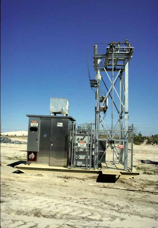

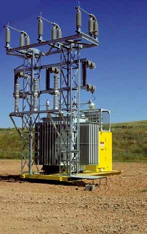

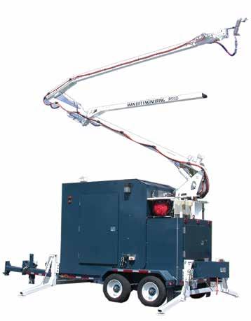
156 Substations 152

 DC Capacitor Tripping with Fail Safe Trip Circuit Heavy-Duty Gear Motor with Spring Charging Mechanism That is")

157 Distribution Vacuum Fault Interrupter Three-Phase Distribution Vacuum Circuit Breakers Type DVCB With Electronic Control The Federal Pacific Three-Phase Distribution Vacuum Circuit Breaker (DVCB) is a rugged and servicable vacuum breaker utilizing a simple straight-line operator and stored energy spring mechanism. Federal Pacific includes the following standard and optional features. Additionally, Federal Pacific specializes in accessories and ratings to meet special application requirements. Standard Features Tested to the Fault Interrupter Requirements of C Operation Counter One Relay Accuracy CT Per Phase Selector Switch (TRIP, CLOSE) DC Capacitor Tripping with Fail Safe Trip Circuit Heavy-Duty Gear Motor with Spring Charging Mechanism That is Electrically and Mechanically TRIP FREE Control Voltage: 120 VAC Electronic Overcurrent Relay with ANSI/IEC Time-Current Curve Selections, Ground Fault Sensing, and Time-Delay Settings 14-gauge NEMA 3R Cabinets Adjustable Height Base Swingout Control Panel for Maintenance Number Markers on All Control Wiring Durable ANSI #61 Gray Paint Thermostatically Controlled Heaters Visible Bottle Wear Indication Visible Load-Side Disconnect with Automatic Grounding Optional Features and Accessories Include: Remote Control for Trip and Close Extra Creep Bushings NEMA 12 Enclosure Pad-Mount Enclosure Stainless-Steel Cabinet and Hardware Extra CTs for relaying and metering Internal or External VTs for Phase Sequence Relaying and/or Control Power SCADA Terminal Points Zone 4 300%g Seismic Duty Lightning Arresters Cabinet Options: Colors, Powder Paint, Stainless-Steel Customized Protection and Control Schemes Standard Ratings Maximum Voltage 15.5 kv 15.5 kv 15.5 kv 27 kv 27 kv BIL 95 kv 95 kv 95kV 125 kv 125kV Continuous Current 600 A 1200A 1000A 600 A 800A Interrupting Rating (Sym) 12.5 ka 18.0 ka 20kA 12.5 ka 16kA Operations Before Maintenance Tamper-Proof Pad-mount Substation Mount 153 Reclosing Vacuum Fault Interrupter
158 Reclosing Vacuum Fault Interrupter Notes 154
159 CIRCUIT INTERRUPTION TECHNIQUES Advantages of Federal Pacific Circuit Interruption Technique Switchgear Components The Federal Pacific Auto-jet Switch is unsurpassed in the industry for its switching capability as an air-insulated load interrupter. It passes the ANSI standards C , C37.57, C37.58 and all the optional and preferred ratings in IEEE C UL listed at 5kV and 15 kv and used extensively in MSHA approved equipment. Interrupter switches available today utilize one of four (4) interrupting/insulating medium technologies: (1) gas (SF6), (2) liquid (oil), (3) vacuum, and (4) air. Gas (SF6) It is an excellent interrupting/insulating medium. However, it is risky since it is on the UN (Kyoto Treaty) list of contaminants as the worst greenhouse gas. It is also very expensive and production capabilities have been reduced, increasing the cost. It is difficult to recapture if it is leaking and tank evacuation for repair requires special handling to avoid contamination and an equally costly storage housing. Arcing in SF6 creates carcinogenic materials, which must be handled and disposed of in a secure manner. Pressure gauges and gas-fill ports are required. Liquid (Oil) It is also a good interrupting/insulating medium, but not as good as SF6. It can be vulnerable to ignition when used as the interrupting medium. Even the biodegradeable types are not perfectly absorbed. In addition, the containers may leak and make for messy, costly handling, clean up and disposal. Testing is necessary to verify the integrity of the liquid dielectric. Vacuum Vacuum is also an excellent interrupting/insulating medium, but involves a sophisticated technology. However, vacuum bottles are also expensive. You cannot see the interrupting contacts so there is no visible disconnect, which is a security requirement for many users. The vacuum contacts also wear and will need to be serviced. Vacuum circuit breakers may require control power for operation such as a battery, which is another maintenance headache. Again, these three technologies are approximately 20% more expensive than our technology, which originated in Europe. In addition, we have added many more improvements to survive in the rugged North and South American and Caribbean markets. Our technology also has none of the risks associated with SF6, oil, and vacuum. Air We use this technology. It is plentiful, easy to control, and has no negative by-products. For this technology, there are two types of circuit-interrupting techniques, namely, ablative and puffer. You are all familiar with the ablative type that uses knife blades that are less robust and therefore not as durable, so they may require maintenance. For example, the ablative switch depends on eroding (consuming) the arc chute or arc compressor (that surround the blade) to generate the gases required to cool and extinguish the arc. That means the arc chute is producing a build-up of carbon inside each time it operates. At some point, it will not be able to generate the necessary gas, which typically will occur in only operations. The Federal Pacific Auto-jet load-interrupter switch employs a unique, reliable method of circuit interruption. The switch is available in ratings to 1200 amperes continuous and interrupting and is designed to provide three-time duty-cycle fault-closing and momentary ratings to 40,000 amperes asymmetrical. A one-time duty-cycle fault-closing rating of 61,000 amperes asymmetrical is also available. By employing a simple puffer mechanism combined with air as a renewable arc-interrupting medium, the Auto-jet switch is unsurpassed in the industry with its complete range of switching capabilities. The switch is capable of 100 full-load circuit interruptions at 600 amperes without maintenance. The performance of the switch is insured by its rugged, heavyduty quick-make, quick-break stored-energy mechanism, which provides high-speed opening and closing independent of the speed of the switch-operating handle. Spring loaded interrupting contacts add increased speed of separation at the point of arc formation to reduce contact wear and to increase the dielectric gap at the instant contacts separate. The heavy-duty construction of the switch blades, contacts, insulators and support frame provides the ruggedness necessary to withstand through multiple operations the electrical, mechanical and magnetic forces generated during all types of switching operations. This capability makes the Auto-jet switch the ideal choice for manual, remote-controlled, and automatic switching in pad-mounted and metal-enclosed switchgear. Comparison Puffer Technology vs. Ablative Technology The puffer interrupter is capable of 100 full-load circuit interruptions at 600 amperes without maintenance compared to the only operations for ablative switches. The puffer interrupter is rated at three (3) time duty-cycle fault-closing at 40,000 amperes without maintenance compared to just one or two-time fault closing at only 22,400 amperes for some ablative switches. Some puffer interrupters have even performed through four fault-closings, which the ablative switches have not. In addition, the puffer interrupter has been tested to 1200 amperes continuous and interrupting with a one-time duty-cycle fault-closing rating of 61,000 amperes asymmetrical. The puffer interrupter has a capability beyond 1000 mechanical operations without requiring service. The operating sequence of the Federal Pacific Auto-jet Load-Interrupter Switch is depicted in the accompanying photographic series. 155

 and puffer assembly starts to move.")


160 Switchgear Components Cutaway Opening Puffer Spring Probe Spring Operating Mechanism Switch closed. Normal current path through lower switch terminal, through switch blades to maincontact and out top terminal pad. Quick-make quick-break mechanism on switch is charged using manual handle and discharges to open switch. As switch blade starts to move, interrupting contacts (probe contact and tulip contact remain engaged) and puffer assembly starts to move. As puffer assembly starts to move, the spring surrounding the puffer assembly begins to compress, as does the spring at the back of the probe. Pump Insulator Main Contact Separates Switch opening. As switch blade continues to move, the probe and puffer springs are further compressed and the initial electrical change occurs as the switch blade starts to separate from the maincontact. Air is being pulled into the chamber of the pump insulator. As the switch blade and main contact separate, current is now diverted through the probe contact, to the tulip contact, through the puffer housing, to the puffer spring, to the back of the main contact, and out the top of the terminal pad. Three and one-half cycles have elapsed. The puffer spring and the probe spring continue to compress as the blade moves further away from the main contact. The springs are nearly fully compressed and air continues to be pulled into the chamber of the pump insulator. As the springs become fully compressed, the probe and the tulip contacts will start to separate Interrupter contacts separate. As the springs are fully compressed, the probe and the tulip contacts will start to separate. The charged puffer spring now quickly pulls the puffer assembly, which includes the tulip contact, back into the pump-insulator chamber. Air in the chamber is forced through the central core of the puffer into the arcing area at the tip of the tulip contact. Simultaneously, the probe spring pulls back the probe. Complete switch operation occurs in a total 5-cycle operating time. At the time of contact separation, not only is the discharging operating mechanism pushing the blade very fast, but the probe and puffer springs are applying energy to rapidly separate the interrupting contacts, which are only in the circuit for 1.5 cycles of the total operating time Switch Open. The switch blade has moved to the fully open position. The process from the instant the switch blade starts to move until circuit interruption is achieved takes only 5 cycles. The arc is extinguished and there is a full dielectric air gap between the switch blade and the main contact. 156

161 AUTO-JET & AUTO-JET II SWITCHES 5-35kV Federal Pacific has designed and manufactured a family of laboratory tested and field proven air-insulated, load-break switches since The original Auto-jet switch and later the Auto-jet II switch provide the same unique method of load interruption, producing a laminated jet of air which extinguishes the arc. Both switches are designed to provide a safe, convenient means of three-pole switching of distribution transformers, cable loops and laterals, and provide automatic or manual switching of preferred and alternate sources. The Auto-jet II was introduced to accommodate smaller sized live-front and dead-front pad-mounted switchgear. The larger sized Auto-jet is used in specialty applications and at 38 kv. Both provide 600 amperes continuous and load-break at rated voltage, 40,000 amperes RMS/ASYM momentary and three-time faultclose capability. Switches rated to 1200 amperes continuous and load-break with a 61,000 ampere one-time duty-cycle fault-closing rating are available. All switches have a heavy-gauge steel frame, which assures proper contact alignment and eliminates any problem of switch-to-enclosure alignment. An optional all stainless-steel switch is available (currentcarrying parts are not stainless-steel).a quick-make, quick-break stored-energy mechanism with heavy-duty, long-life die springs provides high-speed opening and closing independent of the operating handle speed. This high-speed mechanism assures the duty-cycle fault-closing capability and load interruption with the patented Federal Pacific interrupter. The switch blades are made of high conductivity copper. Current transfer from the switch blade through the hinge to the load terminals is accomplished by a unique current transfer means, consisting of a beryllium-copper louvered contact band encircling a copper pin at the hinge point. Magnetic forces, due to a higher than normal current flow, tend to rotate the louvers on the contact band toward a vertical position, providing a higher contact pressure for fault-current duty. Electrical integrity is enhanced by 100% x-rayed cycloaliphatic epoxy insulators. Typical applications include metal-enclosed switchgear, pad-mounted switchgear, metal-enclosed wall-mounted switch cabinets and transformer primary compartments. The switches are available with either left or right hand operator and either direct hex shaft side operation or front chain-drive operation. Switchgear Components AUTO-JET II 15kV, 600 AMPERE AUTO-JET II 15kV, 1200 AMPERE AUTO-JET 34.5kV, 600 AMPERE AUTO-JET RATINGS kv Amperes, RMS Catalog Mounting Fault- Interrupting Number Arrangements Close Net Duty- Weight Nom. Max. Des. BIL Max. Mom. & Cont. Max. Fault-Close Cycle (Lbs.) Load Cable Mag. (ASYM KA) M ➀ ➄ N,H * 3* ➀ ➄ N,H * 3* ➀ ➄ N,H * 3* 178 AUTO-JET II RATINGS kv Amperes, RMS Mounting Fault- Catalog Arrangements Interrupting Close Net Number ➅ Duty- Weight Nom. Max. Des. BIL Max. Mom. & Cont. Max. Fault-Close Cycle (Lbs.) Load Cable Mag. (ASYM KA) M ➀ ➄ N,H ** * 3* M ➃ ➄ N,H ** * 3* ➁ ➄ N,H ** * 3* ➂ ➄ N,H ** * 3* N,H ** T M ➀ ➄ N,H ** * 3* M ➃ ➄ N,H ** * 3* ➁ ➄ N,H ** * 3* ➂ ➄ N,H ** * 3* ➁ ➄ N,H ** * 3* ➂ ➄ N,H ** * 3* For front operation with handle on right. ➅ Mounting arrangements: ➁ ➂ For side operation (3/4"hex operating shaft) handle on right. For side operation (3/4" hex operating shaft) handle on left. (N) Normal (H) Horizontal ➃ For front operation handle on left. ➄ Handles and barriers not included. * The three time duty-cycle fault-closing rating means that the switch can be closed three times into rated fault amperes and remain operable and able to carry and interrupt its rated load current. This switch has a one-time duty-cycle fault-closing rating of 61,000 ampere asymmetrical and a three-time duty-cycle fault-closing rating of 40,000 amperes asymmetrical, following which it will remain operable and able to carry and interrupt load current. ** Barriers installed. 157
162 Switchgear Components Three-Phase Auto-jet Switches Dimensions not to be used for construction purposes. Refer to the factory for detailed construction drawings. S MIN. D MIN. GROUND PLATE 5 1/4 1 1/2 1 3/4 A (MTG.) 3 3/4 MIN UNIT SIDE SHEET 6 5/8 MIN. CLEAR UNIT SIDE SHEET GROUND PLATE 5 1/4 5/8 K L M E F H H N P G 1 1 3/4 3/4 1 1/2 3/4 HEX OPERATING SHAFT 9/16 X 1/12 MTG. SLOTS W SPROCKET PART OF FRONT OPERATOR ASSEMBLY 3 13/16 3/4 V R Front View (Right Hand Operation Shown) Side Operated Front Operated 15kV AJII Switch Only 48 V R AUTO-JET SWITCH kv Class Amps Cont. & Load- Break Catalog Number DIMENSIONS - INCHES A B C D E F G H J K L M N P R S T V W M / /2 27-1/ /8 4-3/8 5-3/4 37-1/2 22-5/ / /8 17-1/ /2 6-1/4 4-5/ / /2 27-1/ /8 4-3/8 5-3/4 37-1/2 22-5/ / /8 17-1/ /2 6-1/4 5-3/ / /2 27-1/ /8 4-3/8 5-3/4 37-1/2 22-5/ / /8 17-1/ /2 6-1/4 5-3/8 AUTO-JET II SWITCH kv Class Amps Cont. & Load- Break Catalog Number DIMENSIONS - INCHES A B C D E F G H J K L M N P R S T V W M 26-5/ /16 3-1/4 24-7/ /4 9-3/4 4-1/ /8 9-5/ / /8 11-1/ /4 12-1/4 3-19/ M 26-5/ /16 3-1/4 24-7/ /4 9-3/4 4-1/ /8 9-5/ / /8 11-1/ /4 12-1/4 3-19/ / /16 3-1/4 24-7/ /4 9-3/4 4-1/ /8 9-5/ / /8 11-1/ /4 12-1/4 3-19/ / /16 3-1/4 24-7/ /4 9-3/4 4-1/ /8 9-5/ / /8 11-1/ /4 12-1/4 3-19/ M / / /8 9-15/16 4-3/ /8 13-7/ /4 14-1/ / /2 9-7/8 3-11/ M / / /8 9-15/16 4-3/ /8 13-7/ /4 14-1/ / /2 9-7/8 3-11/ / / /8 9-15/16 4-3/ /8 13-7/ /4 14-1/ / /2 9-7/8 3-11/ / / /8 9-15/16 4-3/ /8 13-7/ /4 14-1/ / /2 9-7/8 3-11/16 158
163 Single-Phase Auto-jet Switches Dimensions not to be used for construction purposes. Refer to the factory for detailed construction drawings. Front Mount - Side Operated Switchgear Components S MIN. D MIN. GROUND PLATE 5 1/4 J A B 1 3/4 3 3/4 MIN. UNIT SIDE SHEET K L M 1 1/2 E /4 GROUND PLATE 1 3/4 V 3/4 1 1/2 TYP. R Channel Mounted - Hookstick Operated S MIN. K D 5 MTG. 2 1/2 D L M 5 1/4 4 5/16 GROUND PLATE GROUND PLATE E 16 MTG. 19 G 1 3/4 1 1/2 6 ø 9/16 R Application Notes for Single-Phase Auto-Jet Switches: 1) Hookstick-Operated Single-Phase Auto-Jet Switches are rated for 600 amps maximum continuous current. This design is not rated for load switching. 2) Side-Operated Single-Phase Auto-Jet Switches with spring operators are rated for 600 amps maximum continuous current and 600 amps maximum load switching. Type Hookstick Side Operated kv Class kv BIL Catalog Number ➀ For side operation with handle on right. Dimensions - Inches A B D E G J K L M R S V N/A N/A 5-1/4 23-7/8 3-9/16 N/A /4 10-1/ /16 32 N/A N/A N/A 6-3/4 23-7/8 3-9/16 N/A / /8 9-1/4 35 N/A /4 2-13/ /8 2-5/8 4-3/ /4 13-7/ / / See Factory /4 5-1/2 23-7/8 2-5/8 4-3/4 30-1/2 19-1/ / / /2 6-1/4 159
164 Switchgear Components 4 13/16 13 Side and Front Operators 4 5/ / /8 11 1/4 8 9 ø.500 (4) HOLES Type HANDLES Catalog Number Side Operation Front Operation For Use Without Key Front Operation For Use With Key /8 18 7/16 1/4 3/8 16 x 3/4 WELDSTUD 3 3 7/ /16 A A SIX POINT HEX 12 1/4 FOLDED VIEW A-A 15kV, 25kV, 35kV Pad-Mounted Unit Rating kv, BIL NOTES: Phase-to-Phase or Phase-to-Ground Without Barrier Recommended Minimum Clearances In Inches Phase-to-Phase or Phase-to-Ground With Barrier Energized Bus (or device) to Barrier Barrier to Ground in Vicinity of Energized Bus (or device) Terminator Skirts to Barriers /2 3" 1-1/4" 1" 1/2" /2 5" 2" 1-1/4" 1-1/4" /2" 3" 2" 2" Phase-to-Phase or Phase-to-Ground with Barrier: ➁ Minimum Clearance from Energized Parts to Barrier: ➂ Typical Barrier to Ground in Vicinity of Energized Parts: ➃ Minimum Clearance from Terminator Skirts to Barriers: ➄ G. E. Type G Termi-matic Termination System Shown 160 ➀ Minimum clearance from energized parts to electrical ground without barrier.
 depending on the speed of operation required for the specific application.")
165 TYPE PM MOTOR OPERATORS FOR AUTOMATIC SOURCE-TRANSFER AND SCADA CONTROLLED APPLICATIONS 15kV 25kV Switchgear Components Run-and-Trip Style and Fast-Trip Style Federal Pacific Type PM Switch Operators are available in two styles (Run-and-Trip Style and optional Fast-Trip Style) depending on the speed of operation required for the specific application. Regardless of the speed of operation, these motor operators are side mounted to units of 15kV and 25kV live-front or (as illustrated above) dead-front pad-mounted switchgear and provide motor-operated switching for automatic-transfer and remote supervisory-controlled applications on underground power distribution systems. Automatic-transfer unit pictured above illustrates motor-operator mounting in low-voltage compartments at left and foreground enclosure on side at right. Low-voltage enclosure at far right contains micro-processor control and associated wiring. 161

166 Switchgear Components Federal Pacific Motor Operators to Automate Underground Distribution Systems Federal Pacific 15kV and 25kV Manual Models of Pad-Mounted Switchgear can be equipped with motor operators either for automatic source-transfer applications, designated as ATPSI/II Models for Live-Front units and ATPSE Models for Dead-Front units, or for SCADA controlled applications, designated as SCPSI/II Models for Live-Front units and SCPSE Models for Dead-Front units. When equipped with motor operators, Federal Pacific Models of will effect switching operations in a run (charge-spring) and trip sequence in approximately 6-8 seconds or alternately, with an optional Fast-Trip design in approximately 15 cycles. These operating times do not include time delays required for coordination or verification that the event is not permanent. Run-and-Trip Motor Operator The Federal Pacific Type PM Motor Operator, dubbed the runand-trip motor operator includes all the features that have been provided in the past for motor operators used in remotesupervisory control applications. The operating speed for the Run-and-Trip Style Type PM Motor Operator is approximately 4-5 seconds from the instant the motor is actuated through to completion of switch opening or closing. Operation can be effected either automatically when combined with an SEL-451 Relay or remotely when combined with appropriate communications components. Operating time for the automatic source-transfer scheme using the Run-and- Trip Style Type PM Motor Operator is approximately eight (8) seconds. Operating time does not include time required for sensing or time delays required to establish system conditions. These motor operators can also be used in selected configurations of Federal Pacific Metal-Enclosed switchgear. Fast-Trip Style Type PM Motor Operators The operating speed for the Fast-Trip Style Type PM Motor Operator is approximately 6-8 cycles from the instant the motor is actuated through to the completion of switch opening or closing. Operation can be effected either automatically when combined with an SEL-451 Relay or remotely when combined with appropriate communications components. Operating time for the automatic source-transfer scheme using the Fast-Trip Type PM Motor Operator is approximately 15 cycles. Operating time does not include time required for sensing or time delays required to establish system conditions. These motor operators can also be used in selected configurations of Federal Pacific Metal-Enclosed switchgear. Type PM Motor Operators Whether Run-and-Trip Style or Fast-Trip Style, the Federal Pacific Type PM Switch Operator is designed primarily for use on Federal Pacific units of pad-mounted switchgear, replacing the manual operating handle and placed over the manualoperating shaft. However, it may also be applied for specific unique applications when side mounted to bays of metalenclosed switchgear. The run-and-trip motor operator is direct, side-connected to the enclosure of pad-mounted switchgear, and can be similarly connected on bays of metal-enclosed switchgear where space and configuration arrangements permit. A direct, front-connected arrangement is also available for metal-enclosed switchgear (refer to the Federal Pacific Switchgear Product Catalog section on "Automatic Metal-Enclosed Switchgear" and Figure 2 on page 135). The Type PM motor-operator enclosure is an aluminum NEMA 3R, which is rated for outdoor service. The door opening is fully gasketed and seals tight against the door to prevent entry of rain and contamination. The door includes a stainless-steel handle, a continuous, stainless-steel hinge, a storage pocket for the instruction manual, a mounting clip for storage of spare secondary control-circuit fuses, a manual operating handle with storage provisions, and a wind brace to hold the door open. Remote-Supervisory Control Applications The Type PM motor operator includes LOCAL/REMOTE selector switch, local controls, control and battery charger/manager electronic components, AC power and control cable connections, provision for other optional controls, and provision for an RTU and radio/phone. The electronically controlled motor unit is suitable for operation of both 15kV and 25kV 600-ampere and 1200-ampere Federal Pacific Auto-jet Load-Interrupter Switches. The motor unit also includes a decoupler that when decoupled from the switch allows exercising the motor without operating the disconnect switch. The decoupler thus allows functional operation of the motor to be performed as a part of normal maintenance and checkout procedure. The Type PM Motor Operator uses a solid-state controller, which provides consistent and accurate control at each end of the interrupter switch operating stroke. It has a user programmed electronic control that responds to an electronic sensor enclosed within the motor housing. Limit positions are set from the control panel. The controller also provides open and closed position status outputs for an RTU. Figure 1. Federal Pacific Type PM motor operator enclosures include many features providing convenience and security. 162


167 The operating controls, mounted on a panel inside the enclosure, consist of the Local-Remote Selector Switch, the Close-Open Switch and two Indicator Lights to show switch position. Three push buttons, mounted below the control switches behind a secured protective cover; set and adjust the motor-limit controls. Programming controls have safety covers to prevent accidental contact with the limit control during normal local operations. When a CLOSE or OPEN command is given from either the Remote or Local position, the command is sealed in ; and the motor will run to its established limits of travel and cannot be stopped at an intermediate position. The Type PM unit, in most situations, uses 120 volts AC in tandem with DC power supplied by the battery backup system to operate the loadinterrupter switch. An electronic battery charger and battery manager system maintains battery voltage and provides battery condition status output signals for an RTU. Modular construction and plug-in connections make maintenance and service easy. The unit weighs approximately 100 Lb. (45 Kg) without the packing. For the motor operator in remote-supervisory control applications, a 12-volt, 33-amp-hour battery supplies power to the motor-operator assembly and has adequate capacity to power associated components, including an optional radio and RTU. A 24-volt DC battery and charging system is also available. A system combining a battery and 120-volt AC input to a battery charger permits motor operation even when there is a weak battery voltage. The battery charger is temperature compensated. With loss of input power from the charger, the battery can typically maintain the RTU and radio loads for 24 hours. The system includes an electronics package that provides (1) battery overcharge protection and (2) battery testing. Status outputs wired for input to an RTU include: Switch Position, Battery Condition, and Monitoring of Controller Status. Sufficient open space provided on the internal mounting plate for installation of communications components, both a remoteterminal unit (RTU) and radio or other communications portal, for remote-supervisory control operations. When ordering, if specified, an antenna can be installed or provisions provided on the enclosure. Figure 2. Standard-Style Type PM Motor Operator provides space for an RTU, radio and antenna, power supply, control power source and associated components. Figure 3. Fast-Trip Style Type PM Motor Operator has a larger, high-speed motor and space to accommodate an array of communications and control components similar to the Standard-Style Motor Operator. Cover (with yellow label) over motor is interlocked so that when the cover is open, motor operation is blocked to prevent exposure to fast moving parts. Switchgear Components 163
 Type PM Motor Operator.")
168 Switchgear Components a 13b Figure 4. Features of Federal Pacific Standard-Style and Fast-Trip Style (Standard-Style is Pictured) Type PM Motor Operator Aluminum Enclosure Heavy-gauge and corrosion resistant construction with door overlapping opening. 2 Manual Switch-Operating Handle For use in the event that control power is lost - with storage provisions. 3 Instruction Manual Storage Pocket Provides convenient holder for easy reference. 4 Storage Clip for Spare Secondary Fuses Backup protection for vulnerable control circuits. 5 Fully Gasketed Door Opening Combined with rigid construction and deep overlap of door provides protection from the environment. 6 Control Module with LED Status Provides intelligence for controlling operations and status outputs. 7 Power Module with Battery Charger Ensures availability of adequate control power for switching operations. 8 Ribbon Cable Wiring System Simplifies interconnecting control wiring for easy identification and maintenance (on underside of roof). 9 Local/Remote Selector Switch When in Local, allows operation at the unit while blocking remote operation; remote operation is enabled when in remote. 10 Open/Close Operating Switch with Indicating Lamps Permits local electrical switching and annunciates switch position. 11 Fused AC Receptacle Provides power outlet for connection of secondary load. 12 Motor-Travel Set Controls Secured behind cover, allows adjustment of the travel limits for the motor operator. 13a Mounting Plate Provides space for installation of RTU. 13b Radio Provisions (radio by customer) Space permits installation of a radio for communication with a master station. 14 Disconnecting Fuses Protect AC circuits and facilitate easy replacement. 15 Smurff Surge Protector Provide surge protection for control circuits. 16 Heater with Thermostat Keeps interior dry, eliminating potentially damaging moisture. 17 Open/Close Motor-Position Indicator Semaphore target provides indication of actual motor position and switch position when coupled. See Figures 3 and 8 for picture of fast-trip style and additional features that may apply. 18 Padlockable Motor Assembly Insures personnel security against inadvertent operation.see Figures 3 and 8 for picture of fast-trip style and additional features that may apply. 19 Gasketing Shroud Seals motor-operator enclosure to pad-mounted switchgear enclosure (Not visible). 20 Ground Connector On exterior of enclosure allows connecting enclosure to system ground. 21 Removable Access Plate Allows installation of a knockout for entry of control wiring. 22 Padlockable Decoupler Lever Facilitates testing of motor and controls while providing easy secure method of isolation for operating personnel. See Figures 3 and 8 for picture of fast-trip style and additional features that may apply. 23 Padlock Tab 24 Battery with Venting Hose Maintains power availability for motor operation and control equipment. 25 Stainless-Steel Door Hinge Continuous hinge ensures smooth door opening throughout unit life. 26 Door Holder Secures door open. 27 Stainless-Steel Door Handle & Latch Durable components that ensure easy operation. 28 Key Interlock - Coordinate access to fuse compartments by requiring switches to be open. 164
 Motor Open. 23 Switch Decoupled and Motor Closed.")


 Figure 7.")
 position.")

169 Switchgear Components 18 a } } b c d e f g Coupled Position (engaged) Motor Open. 23 Switch Decoupled and Motor Closed. Figure 5. Control module with LED status lamps. Status Outputs a. Loss of AC Power/Loss of Charger Alarm b. No-Go Alarm c. Motor Open Statusv d. Motor Closed Status e. Low-Battery Alarm f. Remote Status g. Pushbutton Coupling Lever Moved To Decoupled Position Behind Padlock Tab. 22 Decoupled Position (disengaged) Figure 7. Padlockable motor and decoupler. Photo at top left shows decoupler in coupled (engaged) position. Photo at bottom right shows decoupler in decoupled (disengaged) position Figure 6. Panel with local controls and motor travel set controls. Figure 8. Open door view of Fast-Trip Style Type PM Motor Operator showing motor and decoupler lever. 165
170 Switchgear Components Notes 166


171 NON-LOADBREAK AND AUTO-JET LOAD-BREAK FUSE MOUNTINGS (All fuse-mounting base plates are galvanized steel) Switchgear Components NON-LOADBREAK FOR SM-4 REFILL UNIT Shown With S&C SM-4Z Fuseholder NON-LOADBREAK FOR DBU, CMU or SMU-20 FUSE UNITS Shown With S&C SM-20 End Fittings NON-LOADBREAK FOR SM-5 REFILL UNIT Shown With S&C SM-5S Fuseholder AUTO-JET FOR SM-4 REFILL UNIT Shown With S&C SML-4Z Fuseholders and includes positive latch indicator. AUTO-JET FOR CURRENT-LIMITING FUSE Shown With AJ-NX type holders and includes positive latch indicator AUTO-JET FOR SMU-20 or DBU FUSE UNIT Shown With S&C SML-20 End Fittings same as Eaton DBU fuses and end fittings and includes positive latch indicator without adapter LOAD-BREAK Auto-jet fuse mountings feature the Federal Pacific EZ-Latch Mechanism with a positive-latch indicator and are available to accommodate S&C Types SM-4 and SMU- 20, Eaton DBU, Cooper: Type NX, and (CT) Type X-Limiter in 15kV and 25kV class. with adapter NON-LOADBREAK disconnect type fuse mountings are available to accommodate a choice of S&C Types SM-4 and SMU-20, Eaton DBU fuses in 15kV and 25kV class and S&C Type SM-5 fuses in 15kV, 25kV and 35kV class. 167

; at (b) the")
 installed in a live-front fuse")
 (c) (a) (b) (a) (b) Figure 2.")
172 Switchgear Components FP Fuse-Unit End Fittings (a) (b) (c) (d) Figure 1. The individual components comprising the Federal Pacific Fuse-Unit End Fittings are pictured at (a); at (b) the components are pictured assembled on a fuse unit; and the combination is shown at (c) installed in a live-front fuse mounting and at (d) in a dead-front fuse mounting. (d) (c) (a) (b) (a) (b) Figure 2. The complete fuse-unit-and-end-fitting assembly is pictured at (a) and the four individual components are illustrated at (b). 168


 Knurled Terminal (b) Lower-Contact Fingers (d) (a) Spring Upper-Gasket Terminal (c)")
173 Fuse-Unit End Fittings - continued Switchgear Components Figure 3. Federal Pacific s lower end-fitting trunnion casting has a guide slot that matches to the raised button on the fuseunit lower-contact ferrule. The silencer/diffuser threads onto the trunnion casting. Figure 4. Federal Pacific s upper end-fitting casting has a raised button inside that matches to the guide groove adjacent to the fuse-unit upper-contact ferrule. Flourescent Section Contact Rod (a) Knurled Terminal (b) Lower-Contact Fingers (d) (a) Spring Upper-Gasket Terminal (c) Rubber-Gasket Seal Lower-Contact Terminal (b) Pull Cord Hinge Pivot Figure 5. The complete refill-unit-and-fuse-holder assembly is pictured at (a) and the four individual components are illustrated at (b). 169
174 Switchgear Components Fuse Manufacturer ➀ Fuse-Unit or Refill Unit Type Application Data Non-Loadbreak Disconnect Mounting (Including Live Parts) Catalog No. * Nom. Ratings kv Max. Des. Holder or End Fittings Catalog No. ** Fuse Ratings Amperes RMS ➁ Interrupting SYM SM R ,500 N/A R ,500 N/A FP ,000 N/A SMU FP ,500 N/A S & C FP ,450 N/A R2 ➂ ,000 ➄ N/A SM-5S R2 ➃ ,000 N/A R2 ➃ ,000 N/A R ,500 N/A Eaton DBU FP ,000 N/A FP ,500 N/A Cooper CMU FP ,000 N/A FP ,500 N/A * Less holder/end fittings ** Includes silencer or snuffler as applicable. Bus for cable termination on left side of mounting. Bus for cable termination on right side of mounting. BIL Max. Fault Close ➀ For fuse application and ordering information refer to applicable S&C and Eaton publications. ➁ Fuse mountings are non-loadbreak. ➂ 4 ➄ Rated 7.2 kv nominal, for use in listed 4.8 kv mountings for system voltages through 4.8 kv. Rated 14.4 kv nominal, for use in listed 13.8 kv mountings. Applies to 7.2 kv refill unit in 7.2 kv holder for 4.8 kv system voltage only. Rating is 37,500 amperes rms symmetrical for 4.16 kv refill unit in 7.2 kv holder for system voltages through 4.16 kv. 170
175 Fuse Manufacturer S & C Eaton Cooper Cooper Fuse Unit or Refill Unit Type SM-4 SMU-20 DBU NX CMU Mounting (Including Live Parts) Catalog No. Application Data Load-break Disconnect Nom. Ratings kv Max. Des. BIL Holder or End Fittings (Including Silencer) Catalog Number Max. Loadbreak Fuse Ratings Amperes RMS Interrupting SYM 3-Time Fault-Close ASYM ,500 20, , , , FP , FP ,000 22, FP ,500 20, FP ,500 20, FP ,000 22, FP ,000 22, FP , FP ,500 20, ,000 40, ,000 40, ,000 40, ,000 40, FP ,000 22, FP ,000 22, FP ,500 20, FP ,500 20,000 For Code 6 fuses only. For Code 5 fuses, also specify adapter Part No. AA5519. Bus for cable termination on left side of mounting. Bus for cable termination on right side of mounting. Switchgear Components Applicable to solidly grounded neutral systems only with fuses connected by single-conductor, concentric-neutral type cable to a transformer or transformers. Rating is 9,400 amperes RMS symmetrical, 15,040 amperes RMS asymmetrical (405 MVA) for all other applications. Less Holder and less end fittings as applicable. Three-time fault-close rating: The Auto-jet II fuse mounting can withstand a fuse holder or fuse end fitting being closed into a fault of the magnitude specified three times when closed briskly without hesitation and remain operable and able to carry and interrupt the continuous current. (Must replace fuse after each interruption.) Refer to Federal Pacific instruction manual on FP-3097 end fittings, S&C instruction manual for SML-4Z holder and SML-20 end fitting maintenance required after each fault close or fault interruption). Ratings express in RMS amperes asymmetrical are 1.6 times the symmetrical values listed. For Cooper (CT) X-Limiter fuses, refer to factory. Mountings a. Part No and 59, 25kV, 125kV. b. Part No and , 15kV, 95kV BIL accepts code 6 fuses direct. Code 5 fuses require adapter Part No. AA5519. NX fused units: Auto-jet II fuse mountings will accommodate one 100 ampere Cooper type NX current-limiting fuse rated 8.3kV, one 100 ampere fuse rated 13.5kV, or one 80 ampere fuse rated 15kV. Three sets of Auto-jet II end fittings and three appropriately rated fuses are required in each fuse compartment. NX fused units: Auto-jet II fuse mountings will accommodate one 100 ampere Cooper type NX current-limiting fuse rated 13.5kV, one 80 ampere fuse rated 15kV, one 40 ampere fuse rated 23kV, or one 50 ampere fuse rated 27kV. Three sets of Auto-jet end fittings and three appropriately rated fuses are required in each fuse compartment. Load-break rating same as maximum continuous current rating. For fuse application and ordering information refer to the applicable S&C, Cooper or Eaton fuse publication. 171
176 Switchgear Components Dimensions: Auto-jet Non-Loadbreak Fuses Dimensions not to be used for construction purposes. Refer to the factory for detailed construction drawings. D 9/16 Dia. NEMA (2) Hole E 2 C (MAX) D E 9/16 Dia. Hole 1 1/2 1/2 F 1 3/4 1 K 5/8 F Q P 1/2 1/2 x 3/4 Mtg. Slots (4) 6 1/2 5 1/2 N SIDE VIEW SM-20 or DBU B B A L M 1 3/4 J H FRONT VIEW (EE-4Z, EE-5S) Right Hand Terminal Pad Shown, NEMA (2) Hole 9/16 Dia. MOUNTING BASE DETAIL SM-20, DBU or CMU 1-11/16 SM-4 2 SM-5 2-9/16 SM-20, DBU or CMU 3-3/8 SM-4 4 SM-5 5-1/8 FRONT VIEW (Fuse Removed) kv Class kv BIL Fuse Unit Type Mounting Catalog Number * Dimensions in Inches A B C D E F G H J K L M N P /2 18-7/ / / / / /2 8-3/4 13-1/2 4-5/8 8-5/8 4-5/ SM /2 18-7/ / / / / /2 8-3/4 13-1/2 4-5/8 8-5/8 4-5/ SMU /4 17-3/4 31-7/8 17-5/8 12-5/ / / /16 4-1/8 1-3/ or DBU /4 22-1/4 35-3/ / / / /4 9-11/ / /16 1-3/4 1-3/4 or CMU /8 28-1/ /4 13-3/4 28-1/4 12-7/8 17-1/4 1-7/ /16 1-3/4 2-7/ / / / /16 9-1/8 12-1/2 10-1/ / / /16 4-3/8 2-1/ /2 18-7/ / / /16 8-3/ /2 9-3/ /16 4-5/ / SM / / /4 19-3/8 14-3/8 9-3/4 20-3/4 10-3/4 14-1/4 4-5/ / / / / / / / / /16 4-5/ / * Holders/End Fittings and Fuse Unit/Refills not included. Bus for cable termination on left side of mounting. Bus for cable termination on right side of mounting. 172
177 1/2 6 1/2 5 1/2 Dimensions: Auto-jet Load-break Fuses Dimensions not to be used for construction purposes. Refer to the factory for detailed construction drawings. 2 1/32 C (MAX) D E F 2 1/32 Switchgear Components 1/2 x 3/4 Mt. Slots (4) B A MOUNTING BASE DETAIL 3/4 9/16 DIA /2 K B MTG. 1 3/4 SIDE VIEW (SM-4, SM-20 or DBU) Right Hand Terminal Pad Shown, NEMA (2) Hole 9/16 Dia. C (MAX) D E F 2 1/32 G FRONT VIEW (Fuse Removed) 2 1/8 SM-4 1 7/8 SM-20 DBU or CMU 1 7/8 NX 4 1/8 SM-4 3 1/2 SM-20 DBU or CMU 3 1/2 NX 1 3/4 Right Hand Terminal Pad Shown, NEMA (2) Hole 9/16 Dia. H SIDE VIEW (NX FUSE) M kv Class kv BIL Fuse Unit Type Mounting Catalog Number * Dimensions in Inches A B C D E F G H J K L M /2 18-7/ /4 17-3/4 12-3/4 9-1/4 18-7/16 8-1/4 12-1/ /8 4-3/ /2 18-7/ /4 17-3/4 12-3/4 9-1/4 18-7/16 8-1/4 12-1/ /8 4-3/8 SM / / /4 11-9/ / / / /8 4-3/ / / /4 11-9/ / / / /8 4-3/ / / /2 19-1/4 14-1/4 9-1/4 19-1/16 9-7/ / / / / /2 19-1/4 14-1/4 9-1/4 19-1/16 9-7/ / /16 SM / / / / /4 11-9/ / /4 15-1/ / / / / / /4 11-9/ / /4 15-1/ / / / /2 19-1/4 14-1/4 9-1/4 19-1/16 9-7/ / / DBU or CMU / /4 18-7/ / /2 34-5/8 19-1/ / /4 16-3/4 9-1/4 11-9/ / /16 9-7/ /4 13-7/ / / / / / / / /4 11-9/ / /4 15-1/ / / / /2 19-1/4 16-1/4 9-1/4 26-1/16 9-7/16 N/A 3 N/A 3-13/ / / /2 19-1/4 16-1/4 9-1/4 26-1/16 9-7/16 N/A 3 N/A 3-13/16 NX ** / / / / /4 11-9/ /8 10-3/16 N/A 3 N/A 3-3/ / / / / /4 11-9/ /8 10-3/16 N/A 3 N/A 3-3/4 For Code 6 fuses only. For Code 5 fuses, also specify adapter Part No. AA5519. Bus for cable termination on left side of mounting. Bus for cable termination on right side of mounting. *Holders/End Fittings and Fuse Unit/Refills not included. **The 15kV NX fuse mountings use Code 5 or 6 fuses, order fuse adapters when using code 5 fuses in this mounting. The 25kV NX fuse mountings use 23kV or 15.5kV Code 6 Fuses. 173
178 Switchgear Components Notes 174


179 FRONT CONNECTED AJ-20 AUTO-JET LOAD-BREAK FUSE MOUNTINGS Switchgear Components Indicator Fuse Open Fuse Closed Accomodates FP-3097 End Fittings and S&C SMU-20 Fuse Unit and also accomodates the Eaton DBU or Cooper CMU and S&C SML-20 fuse and end fittings. Fuse mounting plate is galvanized steel and fuse hinge is electrostatically plated with a hard durable yellow dichromate finish passes "Enclosure Coating System" Section 5 of ANSI C Inset shows positive latch indicator with red target extended, indicating that fuse is fully closed and latched. Fuse Manufacturer and Type Max. Cont. Load-break Fuse Ratings Amperes RMS Interrupting SYM Momentary & Three-Time Fault-Close ASYM Three-Phase MVA SYM At 14.4 Nominal Voltage 95kV BIL S&C SM ,500 20, Eaton DBU Cooper CMU and S&C SMU ,000 22, At 25kV Nominal Voltage 125kV BIL S&C SM ,500 20, Eaton DBU Cooper CMU and S&C SMU ,500 20, In conjunction with Auto-Jet Fuse Mountings. Ratings expressed in RMS amperes asymmetrical are 1.6 times the symmetrical values listed. Unit overall ratings are limited to the lowest component rating. Ratings shown are for fuse mounting interrupter device. Three-time fault-close rating: The Auto-Jet fuse mounting can withstand a fuseholder or fuse with end fitting being closed into a fault of the magnitude specified three times when closed briskly without hesitation and remain operable and able to carry and interrupt the rated continuous current. (Must replace fuse after each interruption.) Refer to Federal Pacific instruction manual on FP-3097 end fittings, S&C instruction manual for SML-4Z holder and SML-20 end fitting and Eaton DBU instructions for maintenance required after each fault close or fault interruption.) 175


180 Switchgear Components Auto-Jet Load-break Fuse The Auto-Jet fuse mounting has an integral stored-energy loadbreak device that permits single-pole live switching in single-phase or three-phase circuits by the use of an ordinary hotstick. In addition, when the fuse is fully inserted and positively latched, the EZ-Latch mechanism has a positive-latch indicator that provides a semaphore that extends. The integral load interrupter has a three-time fault-close duty cycle when, without hesitation, the fuse is briskly closed. The overall unit rating may be limited by the fuse rating. Illustration of Auto-Jet Fuse Interrupter Latch Indicator Figure 1. Closed: Positive Latch Indicator Extended (see inset). Hookstick Ready To Open. The same unique laminated air jet interrupter system used in the three-pole group-operated switches is applied in the Auto-Jet load-break fuse mountings. Figures 1 through 3 shown below illustrate the basic operation of the Auto-Jet Interrupter device. Load-break Fuse Operation 1. Insuring latched fuse, verify extended Positive Latch Indicator. Install grappler tool in pull ring of fuse end fitting as shown. (Figure 1) 2. Pull the fuse open with a single sharp continuous motion to the fully open position (45 ). Maintain downward force on fuse pull ring until fuse opening motion has ceased. This downward force will prevent tendency for fuse to bounce toward the closed position. Caution: Do not assume that an open fuse position indicates the fuse to be de-energized. 3. Re-install grappler onto fuse assembly with the cone positioned in the pull ring on the upper end fitting and with the fingers of the grappler tool cradling the tube of the fuse unit. Then, while grasping the hotstick firmly, lift fuse assembly up and out of mounting. 4. Re-fuse using procedures as included with replacement fuse unit. 5. Re-install grappler onto fuse assembly and place fuse assembly into fuse mounting in the 45 open (disconnect) position. 6. Insert grappler prong into fuse pull ring and, while maintaining a downward force on the fuse pull rings, push briskly on the fuse assembly, completing the closing stroke in one motion. 7. Before removing grappler from fuse pull ring, verify that the Positive Latch Indicator is extended indicating that the fuse is fully latched. If the indicator is not extended (DO NOT PULL OPEN), push firmly until the latch indicator target extends to assure that the fuse is completely closed and latched. Figure 2. Main Contacts Have Parted, Puffer Spring Charged, and Interrupter Parted. Figure 3. Holder Parted, Auto-jet Reset For Next Closing Operation. Positive Latch Indicator Retracted and Out of View. 176 Components Purchased Separately 14.4kV Nominal SM-4 fuse mounting requires one S&C Cat. No SML-4Z fuseholder and one S&C SM-4 fuse refill. SM-20 or DBU fuse mounting requires one set of Federal Pacific FP-3097 end fittings or S&C Cat. No SML-20 fuse end fittings and one S&C SMU-20 fuse unit or one set of Federal Pacific FP-3097 end fittings or Eaton DBU Cat. Number DBU-EFID end fittings and one DBU fuse unit. 25kV Nominal SM-4 fuse mounting requires one S&C Cat. No SML-4Z fuseholder and one S&C SM-4 fuse refill. SMU-20 or DBU fuse mounting requires one set of Federal Pacific FP-3097 end fittings or S&C Cat. No SML-20 fuse end fittings and one S&C SMU-20 fuse unit or one set of Federal Pacific FP-3097 end fittings or Eaton DBU Cat. Number DBU-EFID end fittings and one DBU fuse unit.
181 Federal Pacific switch and bus insulators, bushings, and bushing wells made from the highest quality cycloaliphatic epoxy resins and selected fillers to achieve an optimum balance of electrical and mechanical characteristics. Standard color is skytone gray. FEDERAL PACIFIC EPOXY INSULATORS AND BUSHINGS Each Federal Pacific EEpoxy Class A insulator is equipped with eight aluminum 3/8" - 16 full-threaded inserts 3/4" deep, four on each end, in the standard 2" bolt circle. Standard color is Skytone Gray. Switchgear Components Shown below are minimum test values for Federal Pacific insulators, bushings, and bushing wells, obtained during independent electrical and mechanical testing in accordance with the applicable test methods specified by the latest edition of ANSI C29.1 and ANSI 386. INSULATORS Federal Pacific EEpoxy insulators are made to the exacting requirements of ANSI C29.1 and are recommended for switch and bus applications which require superior arc and track resistance, excellent mechanical strength, exceptionally high leakage (creep) distance for contamination resistance and self-scouring, non-weathering performance. BUSHING WELLS AND BUSHINGS Federal Pacific bushings and bushing wells meet all the design criteria in ANSI 386. By meeting this standard, all Federal Pacific bushings and bushing wells will interface with matching load-break and non-loadbreak inserts and elbows. The XL bushings and bushing wells feature a removable stud and include four aluminum inserts in a 3-inch square pattern on the interface end and two inserts in a 2-inch bolt circle centered on the 1/2-inch diameter tapped conductor rod on the bus end. The XM bushings and bushing wells are similar except the interface end, clamped to the mounting surface in a 3-bolt pattern using stainless steel plate and hardware. Mechanical and Electrical Ratings Components Insulators 200A Bushing Wells 600A Bushings Description Design Parameter EEpoxy EEpoxy EEpoxy * EEpoxy EEpoxy EEpoxy Voltage Nominal, kv Max Design, kv BIL, kv Dimensions Leakage Distance, Inches / / / / /16 Height, Inches, Dim. "L" /4 6-3/8 8-5/8 6-1/4 8-1/2 6-3/8 8-5/8 Mechanical Ratings Cantilever, Ultimate 2.5" above top, 1,250 1,100 1,100 1,000 1,000 1,000 1,000 1,000 1,000 1,000 1,000 1,000 1,000 Pounds Tensile, Pounds 3,000 3,000 3,000 3,000 2,500 2,500 3,000 3,000 3,000 3,000 3,000 3,000 3,000 Torsion, Inch Pounds 3,500 3,500 3,500 3, ,000 2, Compression, Pounds 20,000 20,000 20,000 20,000 N/A N/A 10,000 10,000 10,000 10,000 10,000 10,000 10,000 Net Weight, Pounds (Approx.) *Available when creepage distance more than 18.3" is required. Tensile and torsion force applied to bushing-well conductor stud. Catalog number applies to bushing well or bushing only. For clamp ring and mounting hardware, add suffix "-01" to catalog number. Disclaimer and Limitation of Liability: The information contained in this data sheet is accurate to the best of our knowledge. All data and recommendations are based on tests we believe to be reliable. All products are designed strictly for specific applications. It is the sole responsibility of the buyer to determine the suitability of the products for any other contemplated use. If the products are used for any application other than those specified, Federal Pacific will not be liable for any injury or damage arising from their use. XL XM XM XL XL XM XM


182 Switchgear Components Federal Pacific insulators manufactured from cycloaliphatic epoxy resins in the Federal Pacific switchgear plant by the automatic pressure gelation (APG) process; developed in Switzerland over fifty years ago, and widely used globally. It has developed to a technologically advanced state used in the manufacture of a broad range of indoor and outdoor high-voltage electrical components. In this process, the cycloaliphatic epoxy resin hardener and various pre-mixed fillers and additives for properties and process control are combined in specially designed, computer-controlled equipment; formulations are developed by supplier engineers through exhaustive testing and field experience. The insulators and bushings are designed to meet precise requirements for a specific application. These formulations are balanced for high-voltage, high strength, non-tracking, self-scouring, nonweathering applications in extremes of high temperature and sub-zero cold. The mix is thoroughly degassed under high vacuum and transferred to automatic presses. Here it is injected into highly-polished tool steel molds and formed under heat and pressure into compact, high leakage-distance, engineered thermoset contours to enhance the electrical and mechanical characteristics. Firmly imbedded in each end are full-threaded inserts as specified. The cycloaliphatic epoxy components develop a high degree of polymer cross-linking to give optimum thermal, mechanical and electrical properties. All epoxy components are x-rayed, visually inspected for surface irregularities, color, integrity, and general appearance, and are serialized. The in-process examination is given using a 110kV real time fluoroscopic x-ray for a 100 percent, 360, end-to-end inspection. Trained examiners look for any signs of internal voids, cracks, non-bonded inserts or other defect that could cause or lead to problems under voltage, thermal or mechanical stress in future years. FP Cyclo-Aliphatic Epoxy Only after this rigidly controlled manufacturing process, x-ray inspection and any final de-flashing or cleaning which might be required are the insulators stamped "X-ray OK" and logged by serial number in quality assurance records assurance that the Federal Pacific quality is locked in. Finished insulators are 100%, 360, end-to-end fully inspected internally by 100kV real-time fluoroscopic x-ray. Federal Pacific cycloaliphatic epoxy insulators provide superior performance, serving as bus supports, interrupter housings, bushings and bushing wells on 5kV through 38kV products. 178


183 EEpoxy Insulators 2" B.C. EEpoxy Bushing Wells Switchgear Components 4-1/ /4 L L 3-1/ /4 XL Bushing Wells XM Bushing Wells TYP DIA BOLT CIRCLE L L 2" DIA BOLT CIRCLE 5.00 DIA 179
TYPE PSI/II PADMOUNT SWITCHGEAR 15KV 25KV
 Cutler Hammer SECTION PB-1A-110 PAGE 1 Replaces April, 1996 TYPE PSI/II PADMOUNT SWITCHGEAR 15KV 25KV The PSI/II Padmount is the second generation of switchgear in the PSI switchgear family. The PSI/II
SWITCHGEAR DIVISION PRODUCT PROFILES
 SWITCHGEAR DIVISION PRODUCT PROFILES Metal-Enclosed Load-Interrupter Switchgear Product Profiles Three-Phase, Group-Operated Load-Interrupter Switches with Fuses in Single and Multi-Bay Assemblies Manual,
STANDARD SPECIFICATION FOR LIVE-FRONT 15KV AND 25KV PSI/II PAD-MOUNTED SWITCHGEAR
 STANDARD SPECIFICATION FOR LIVE-FRONT 15KV AND 25KV PSI/II PAD-MOUNTED SWITCHGEAR A. General 1. Product The pad-mounted switchgear shall be PSI/II design as manufactured by Federal Pacific and shall conform
STANDARD SPECIFICATION FOR TYPE PLD LIVE-FRONT/DEAD-FRONT PAD-MOUNTED SWITCHGEAR 15kV 25kV A. General
 Page 1 STANDARD SPECIFICATION FOR TYPE PLD LIVE-FRONT/DEAD-FRONT PAD-MOUNTED SWITCHGEAR 15kV 25kV A. General 1. Product The pad-mounted switchgear shall be in accordance with the applicable plans, drawings,
DEAD-FRONT PAD-MOUNTED SWITCHGEAR 15kV 25kV
 TYPE PSE MANUAL DEAD-FRONT PAD-MOUNTED SWITCHGEAR 15kV 25kV Figure 1 Federal Pacific Dead-Front PSE (available as UL Listed) contains an integrated system of fuses and switches with access control features
PAD-MOUNT SWITCHGEAR 15kV 25kV 35kV
 PAGE 1 TYPE PSI PAD-MOUNT SWITCHGEAR 15kV 25kV 35kV INSTRUCTIONS For Installation and Operation INTRODUCTION... 1 Receiving... 1 Handling... 1 Storage... 1 GENERAL DESCRIPTION... 1 SAFETY FEATURES... 1
STANDARD SPECIFICATION FOR PAD-MOUNTED CAPACITOR BANKS FOR 15kV or 25kV APPLICATIONS
 A. General 1. Product The pad-mounted capacitor banks shall be in accordance with the applicable plans, drawings, and one-line diagrams and shall conform to these specifications. 2. Assembly The outdoor
S&C Manual PME Pad-Mounted Gear
 S&C Manual PME Pad-Mounted Gear Outdoor Distribution,. kv and 5 kv S&C Manual PME Pad-Mounted Gear... Featuring Elbow-Connected Encased Components. S&C Manual PME Pad-Mounted Gear brings in-air insulation,
15-kV Wall-Mount Switchgear Three-Phase Indoor/Outdoor 600 Amp S&C Mini-Rupter Switch
 Page 1 2015 Kinked roof prevents standing moisture Glass reinforced barriers meet NEMA GPO-3 Standards 0.625" diameter copper ground bar Elliott air-insulated bushings accept IEEE Standard inserts and
ME Switchgear with Vacuum Circuit Breaker and Auto-jet II Switch with Ground Position
 LET S BE PACIFIC November 0 Volume Number 5 ME Switchgear with Vacuum Circuit Breaker and Auto-jet II Switch with Ground Position Federal Pacific has the capability to engineer, fabricate and assemble
15-kV Live Terminal 600 Amp Group Operated Pad-Mounted Metal-Enclosed Outdoor Switchgear 140 Amp (Max) Clip Mount Current-Limiting Fuses
 Clip Mount Current-Limiting Fuses") Page 1 2015 Heavy duty 11-gauge steel enclosure is all-welded construction for long life Corrosion proof nameplate is located to provide easy access for the operator Glass reinforced barriers meet NEMA
Page 1 2015 Heavy duty 11-gauge steel enclosure is all-welded construction for long life Corrosion proof nameplate is located to provide easy access for the operator Glass reinforced barriers meet NEMA
Specifications. S&C Power Fuses Types SM and SMLa. For use with SM Refill Units or SMU Fuse Units. Indoor Distribution (4.16 kv through 34.
 S&C Power Fuses s SM and SMLa Indoor Distribution (4.16 through 34. ) For use with SM Refill Units or SMU Fuse Units Specifications Conditions of Sale STANDARD: Seller s standard conditions of sale set
SPECIFICATION BULLETIN
 SPECIFICATIONS Conditions of Sale STANDARD: Seller s standard conditions of sale set forth in Price Sheet 150 apply, except as modified under WARRANTY QUALIFICATIONS on page 3. SPECIAL TO THIS PRODUCT:
35-kV Safefront SuperWell Mini-Switch Source Isolated Pad-Mounted Switchgear 50 Amp (Max) Clip-Mounted Current Limiting Fuses
 Clip-Mounted Current Limiting Fuses") Page 1 2016 EPMR-35-311S-R2/ESW-CM9 Three Phase Two Ways per Phase 200 Amp 35 kv Class Eaton s CPS LRTPs 50 Amp (Max) 27 kv Clip-Mounted NX Fuse Provisions 21.1/36.6 kv Grounded Wye Max Design, 150 kv
Page 1 2016 EPMR-35-311S-R2/ESW-CM9 Three Phase Two Ways per Phase 200 Amp 35 kv Class Eaton s CPS LRTPs 50 Amp (Max) 27 kv Clip-Mounted NX Fuse Provisions 21.1/36.6 kv Grounded Wye Max Design, 150 kv
Specification Pad-Mounted Capacitor Bank with Dual Fusing Integral Load-Interrupter on Line-Side Fuse Mountings
 Page 1 Specification Pad-Mounted Capacitor Bank with Dual Fusing Integral Load-Interrupter on Line-Side Fuse Mountings I. General This specification covers the design requirements for a pad-mounted capacitor
Design Build Deliver. Metal Enclosed Switchgear, 5-35kV 1200 A Maximum Loadbreak, 4000 A Maximum Non-Loadbreak
 Metal Enclosed Switchgear, 5-35kV 1200 A Maximum Loadbreak, 4000 A Maximum Non-Loadbreak Powergrid Solution s Metal Enclosed Switchgear has many different customizable options and configurations. Customers
WARNING. TYPE PSI/II PAD-MOUNT SWITCHGEAR with Non-Loadbreak Fuse Mountings 15kV 25kV INSTRUCTIONS. Qualified Persons. For Installation and Operation
 PAGE 1 TYPE PSI/II PAD-MOUNT SWITCHGEAR with Non-Loadbreak Fuse Mountings 15kV 25kV QUALIFIED PERSONS...1 SAFETY INFORMATION...2 INTRODUCTION...3 Receiving...3 Handling...3 Storage...3 GENERAL DESCRIPTION...3
Typical Specification
 Engineered to Order Built to Last Typical Specification VAULT VRPFI, TWO POSITION, ROTARY PUFFER SWITCHGEAR PART 1- GENERAL 1.1 DESCRIPTION A. The switch shall consist of manually operated load interrupting,
Guide Specification. Three-Phase Solid Dielectric Trident-SR with SafeVu Integral Visible Break
 Part 1-GENERAL 1.1 DESCRIPTION Guide Specification Three-Phase Solid Dielectric Trident-SR with SafeVu Integral Visible Break The switchgear shall consist of magnetically actuated solid dielectric insulated
SUBSTATION VACUUM CIRCUIT BREAKER (38KV)
") SUBSTATION VACUUM CIRCUIT BREAKER (38KV) For more than four decades, Myers Power Products has led the switchgear market in quality for the electric industry, delivering highly reliable products for utilities
SUBSTATION VACUUM CIRCUIT BREAKER (38KV) For more than four decades, Myers Power Products has led the switchgear market in quality for the electric industry, delivering highly reliable products for utilities
SUBSTATION VACUUM CIRCUIT BREAKER (25.8 / 27KV)
") SUBSTATION VACUUM CIRCUIT BREAKER (25.8 / 27KV) For more than four decades, Myers Power Products has led the switchgear market in quality for the electric industry, delivering highly reliable products
SUBSTATION VACUUM CIRCUIT BREAKER (25.8 / 27KV) For more than four decades, Myers Power Products has led the switchgear market in quality for the electric industry, delivering highly reliable products
Medium Voltage Metal-Enclosed Switches
 Medium Voltage Metal-Enclosed Switches Outdoor Medium Voltage Switch.1 Introduction Product Selection Guide....................................2 Medium Voltage Switch MVS Product Description......................................
SUBSTATION VACUUM CIRCUIT BREAKER (15.5KV)
") SUBSTATION VACUUM CIRCUIT BREAKER (15.5KV) For more than four decades, Myers Power Products has led the switchgear market in quality for the electric industry, delivering highly reliable products for utilities
SUBSTATION VACUUM CIRCUIT BREAKER (15.5KV) For more than four decades, Myers Power Products has led the switchgear market in quality for the electric industry, delivering highly reliable products for utilities
ME series dead-front fused sectionalizing enclosures MEC current limiting fusing and MEP power fusing 200 Amperes,15-25 kv
 ME series dead-front fused sectionalizing enclosures MEC current limiting fusing and MEP power fusing 200 Amperes,15-25 kv ABB ME series fused sectionalizing enclosures ABB's dead-front Padmount ME series
35-kV Safefront 200 Amp SuperWell Primary Capacitor Station Pad-Mounted Outdoor
 Page 1 2016 EPM-PCS-35-320P-R2/ESW-GCM6-2S-SA Three Phase Two Ways per Phase 200 Amp 35 kv Class Eaton's CPS LRTPs 35 kv Elliott Air-Insulated SuperWell Bushings 21.1/36.6 kv Grounded Wye Max Design, 150
Section SWITCHBOARDS. Introduction. Part 1 - General. Related Work
 Section 16435 - SWITCHBOARDS Introduction Part 1 - General Related Work Section 16070 Seismic Anchorage and Restraint Section 16075 Electrical Identification Section 16080 Power Distribution Acceptance
Underground Distribution Switchgear
 Underground Distribution Switchgear Functional Specification Guide Functional Specification for 15 kv, 25 kv, or 35 kv Underground Distribution Switchgear 1. Scope 1.1. This specification applies to three-phase,
AUTOMATIC-TRANSFER PAD-MOUNTED SWITCHGEAR LIVE-FRONT - TYPE ATPSI/II DEAD-FRONT - TYPE ATPSE 15kV 25kV
 AUTOMATIC-TRANSFER PAD-MOUNTED SWITCHGEAR LIVE-FRONT - TYPE ATPSI/II DEAD-FRONT - TYPE ATPSE 15kV 25kV Federal Pacific of Bristol, Virginia offers Live-Front and Dead-Front Automatic Source Transfer Pad-Mounted
C1000 Series Automatic Cap Bank
 C1000 Series Automatic Cap Bank Metal Enclosed - Medium Voltage Capacitors Assemblies Fixed / Auto Medium Voltage 5, 15, 25 and 35 kv Class Customized to your specifications The Reactive Power Solution
Specifications. S&C Alduti-Rupter Switches with Power Fuses Outdoor Distribution (14.4 kv through 46 kv)
") Outdoor Distribution (4.4 kv through 46 kv) Specifications Conditions of Sale STANDARD: Seller s standard conditions of sale set forth in Price Sheet 50 apply, except as modified under WARRANTY QUALIFICATIONS
Outdoor Distribution (4.4 kv through 46 kv) Specifications Conditions of Sale STANDARD: Seller s standard conditions of sale set forth in Price Sheet 50 apply, except as modified under WARRANTY QUALIFICATIONS
Medium Voltage Metal-Enclosed Switches
 Medium Voltage Metal-Enclosed Switches Outdoor Medium Voltage Switch.1 Medium Voltage Switch MVS Product Description............................................. 2 Application Description..........................................
15-kV Safefront 200 Amp Primary Capacitor Station Pad-Mounted Outdoor
 Page 1 2015 Heavy-duty 11-gauge steel enclosure is all-welded construction for long life Clear polycarbonate removable safety barrier separates upper and lower compartment (supplied only with internally
INDEX Welcome 1.2 Contacting Powergrid Solutions, Inc. 1.3 Terms Of Usage 1.4 Product Codes and Descriptions
 INDEX SECTION 1 INTRODUCTION 1.1 Welcome 1.2 Contacting Powergrid Solutions, Inc. 1.3 Terms Of Usage 1.4 Product Codes and Descriptions SECTION 2 PADMOUNTED ENCLOSURES/CABLE SWITCHING/TERMINATING GEAR
35-kV Safefront 200 Amp SuperWell Primary Metering Station Pad-Mounted Outdoor
 35-kV Safefront 2 Amp SuperWell 5-33 Page 1 216 EPM-PMS-35-311P-R2/ESW Three Phase Two Ways per Phase 2 Amp 35 kv Class Eaton's CPS LRTPs NEMA Standard Outdoor Instrument Transformer Provisions 21.1/36.6
35-kV Safefront Mini-Switch Source Isolated Pad-Mounted Switchgear 50 Amp (Max) Clip-Mounted Current-Limiting Fuses
 Clip-Mounted Current-Limiting Fuses") Page 1 2016 Heavy duty 11-gauge steel enclosure is all-welded construction for long life 11-gauge steel equipment plate is rigid for easier elbow operation Parking stands for the upper two phases extend
Page 1 2016 Heavy duty 11-gauge steel enclosure is all-welded construction for long life 11-gauge steel equipment plate is rigid for easier elbow operation Parking stands for the upper two phases extend
Underground Distribution Switchgear
 Underground Distribution Switchgear Functional Specification Guide Functional Specification for 15 kv, 25 kv, or 35 kv Underground Distribution Switchgear 1. Scope 1.1. This specification applies to three-phase,
15-kV Safefront Mini-Switch Source Isolated Pad-Mounted Switchgear 140 Amp (Max) Clip-Mounted Current-Limiting Fuses
 Clip-Mounted Current-Limiting Fuses") Page 1 2016 Heavy duty 11-gauge steel enclosure is all-welded construction for long life 200 Amp Elliott air-insulated bushing wells accept IEEE Standard inserts and elbows ushing wells may be added or
Page 1 2016 Heavy duty 11-gauge steel enclosure is all-welded construction for long life 200 Amp Elliott air-insulated bushing wells accept IEEE Standard inserts and elbows ushing wells may be added or
Michigan State University Construction Standards SECONDARY UNIT SUBSTATIONS PAGE
 PAGE 261116-1 SECTION 261116 PART 1 - GENERAL 1.1 RELATED DOCUMENTS A. Drawings and general provisions of the Contract, including General and Supplementary Conditions and Division 01 Specification Sections,
Specifications. S&C Alduti-Rupter Switchesa Indoor Distribution (4.8 kv through 34.5 kv) Conditions of Sale SPECIAL TO THIS PRODUCT: How to Order
 Conditions of Sale SPECIAL TO THIS PRODUCT: How to Order") S&C Alduti-Rupter Switchesa Indoor Distribution ( kv through kv) Specifications Conditions of Sale STANDARD: Seller s standard conditions of sale set forth in Price Sheet 0 apply. SPECIAL TO THIS PRODUCT:
S&C Alduti-Rupter Switchesa Indoor Distribution ( kv through kv) Specifications Conditions of Sale STANDARD: Seller s standard conditions of sale set forth in Price Sheet 0 apply. SPECIAL TO THIS PRODUCT:
Descriptive bulletin. Medium voltage load interrupter switchgear Reliable, low maintenance and economical for distribution applications
 Descriptive bulletin Medium voltage load interrupter switchgear Reliable, low maintenance and economical for distribution applications General overview Reliable, low maintenance and economical Load Interrupter
S&C Recloser Bypass Disconnects
 S&C Recloser Bypass Disconnects Outdoor Distribution (14.4 kv through 34.5 kv) Application S&C Recloser Bypass Disconnects are station-type devices used to bypass and isolate automatic circuit reclosers
A. The ratings for the integrated pad-mounted gear shall be as designated below:
 Section 16310 - PRIMARY SWITCH STATION PART 1 GENERAL 1.01 Description of Work 1.02 Ratings A. The pad-mounted gear shall be in accordance with the one-line diagram, and shall conform to the following
DESIGN GUIDELINES LOW VOLTAGE SWITCHGEAR PAGE 1 of 5
 DESIGN GUIDELINES LOW VOLTAGE SWITCHGEAR PAGE 1 of 5 1.1. APPLICABLE PUBLICATIONS 1.1.1. Publications listed below (including amendments, addenda, revisions, supplements, and errata), form a part of this
A. Submit manufacturer's literature and technical data before starting work.
 SECTION 16425 SWITCHBOARD PART 1 GENERAL 1.01 SUMMARY A. Related Section: 1. 16450 - Grounding. 1.02 SUBMITTALS A. Submit manufacturer's literature and technical data before starting work. B. Submit Shop
Switchgear Skid, C1192
 CUSTOM SOLUTIONS 15kV Modular Stairs stored on floor in front of battery bay Ground grid stored on front tongue of trailer Stairs deployed for unit access Storage box for fencing materials and other parts
15-kV Live Terminal 200 Amp Mini-Switch Source-Isolated Pad-Mounted Switchgear 40 Amp (Max) Arc-Strangler NX Fuses
 Arc-Strangler NX Fuses") Page 1 2015 Heavy duty 11-gauge steel enclosure is all-welded construction for long life Door safety barrier removal instructions Safety latches on the door safety barriers, front and rear, are insulating
Page 1 2015 Heavy duty 11-gauge steel enclosure is all-welded construction for long life Door safety barrier removal instructions Safety latches on the door safety barriers, front and rear, are insulating
S&C Loadbuster Disconnect Switches. Outdoor Distribution (14.4 kv through 34.5 kv)
") S&C Loadbuster Disconnect Switches Outdoor Distribution ( kv through 34.5 kv) S&C s Loadbuster Disconnect Switches, when used with S&C s Loadbuster tool, provide the ultimate in distribution live-switching
S&C Loadbuster Disconnect Switches Outdoor Distribution ( kv through 34.5 kv) S&C s Loadbuster Disconnect Switches, when used with S&C s Loadbuster tool, provide the ultimate in distribution live-switching
SECTION ENCLOSED SWITCHES AND CIRCUIT BREAKERS
 SECTION 26 28 16 ENCLOSED SWITCHES AND PART 1 - GENERAL 1.1 SUMMARY A. Section includes the following individually mounted, enclosed switches and circuit breakers rated 600V AC and less: 1. Fusible switches.
S&C Loadbuster Disconnects
 S&C Loadbuster Disconnects Outdoor Distribution ( kv through 34.5 kv) With these outstanding features... Up to -ampere continuous ratings, 40,000-ampere RMS asymmetrical momentary ratings Designed for
Solid Dielectric, Single Phase Recloser
 Solid Dielectric, Single Phase Recloser Catalog O-vsp17 Viper-SP Viper-SP solid dielectric, single phase recloser combines the time-proven reliability of electronically controlled, vacuum fault interrupters
Metal-Enclosed Switches. Medium Voltage. Medium Voltage Metal-Enclosed Switches Contents
 January 2003 Vol. 1, Ref. No. [1011] -1 Medium Voltage Metal-Enclosed Switches Contents Description Page MVS................................... -2 and Breaker MSB........................ -3 Metal-Enclosed
Horizontal Circuit Switchers
 > Transformer Protection > CIRCUIT SWITCHERS C A T A L O G B U L L E T I N General Application Southern States Types CSH and CSH-B Horizontal Circuit Switchers provide an economical, versatile, space saving
Underground Distribution Switchgear
 Underground Distribution Switchgear Type VFI, Vacuum Fault Interrupter Switchgear Functional Specification Guide Functional Specification for 15 kv, 25 kv, or 35 kv Underground Distribution Switchgear
35-kV 200-kV BIL Apparatus Bushings B Series (bolt-in) for Elbow to Air-Insulated Service 200 Amp, 600 Amp, 900 Amp and 1250 Amp
 for Elbow to Air-Insulated Service 200 Amp, 600 Amp, 900 Amp and 1250 Amp") Page 1 2018 Grounded Metal Equipment Plate Equipment Connection 35 kv Separable Insulated Connector (elbow) Bus Bar or Other Component Grounded Metal Equipment Plate Equipment Connection Bus Bar or Other
Page 1 2018 Grounded Metal Equipment Plate Equipment Connection 35 kv Separable Insulated Connector (elbow) Bus Bar or Other Component Grounded Metal Equipment Plate Equipment Connection Bus Bar or Other
35-kV Apparatus Bushings B Series (bolt-in) for Elbow to Air-Insulated Service 200 Amp, 600 Amp, 900 Amp and 1250 Amp
 for Elbow to Air-Insulated Service 200 Amp, 600 Amp, 900 Amp and 1250 Amp") Page 1 2018 Grounded Metal Equipment Plate Equipment Connection Bus Bar or Other Component 35 kv Separable Insulated Connector (elbow) Grounded Metal Equipment Plate Equipment Connection Bus Bar or Other
Page 1 2018 Grounded Metal Equipment Plate Equipment Connection Bus Bar or Other Component 35 kv Separable Insulated Connector (elbow) Grounded Metal Equipment Plate Equipment Connection Bus Bar or Other
Unit Substation Transformers 5 and 15 KV Class
 Transformers 5 and 15 KV Class 85 General Information Description Federal Pacific unit substation transformers are available in a wide variety of types and ratings to provide reliable and versatile electrical
Three-Phase Pole Mounted Recloser
 Three-Phase Pole Mounted Recloser Page 1 of 8 Table of Contents 1 GENERAL... 3 2 CONSTRUCTION... 3-5 3 BUSHINGS... 5 4 LINE CONNECTOR... 5 5 TOOLS....5 6 NAMEPLATES..6 7 PAINT... 6 8 EXTERNAL HARDWARE
25-kV Apparatus Bushings B Series (bolt-in) for Elbow to Air-Insulated Service 200 Amp, 600 Amp, 900 Amp and 1250 Amp
 for Elbow to Air-Insulated Service 200 Amp, 600 Amp, 900 Amp and 1250 Amp") Page 1 2018 Grounded Metal Equipment Plate Equipment Connection Bus Bar or Other Component 15 kv or 25 kv Separable Insulated Connector (elbow) Equipment Connection Power Cable Power Cable ELRIM Cycloaliphatic
Page 1 2018 Grounded Metal Equipment Plate Equipment Connection Bus Bar or Other Component 15 kv or 25 kv Separable Insulated Connector (elbow) Equipment Connection Power Cable Power Cable ELRIM Cycloaliphatic
DEADFRONT VACUUM INTERRUPTER PAD-MOUNTED SWITCHGEAR 15kV 25kV
 TYPE PVE DEADFRONT VACUUM INTERRUPTER PAD-MOUNTED SWITCHGEAR 15kV 25kV Figure 1. Federal Pacific PVE Models Incorporate s With Visible Disconnects Into A Rugged Heavy-Gauge Steel Enclosure Featuring Air-Insulated,
7. SERVICES OVER 600 VOLTS
 7. SERVICES OVER 600 VOLTS 7.1 GENERAL The Company shall always be consulted to obtain required design criteria where service is contemplated.preliminary plans of the Customer shall be submitted for review
Horizontal Circuit Switchers
 > Transformer Protection > CIRCUIT SWITCHERS C A T A L O G B U L L E T I N General Application Southern States Types CSH and CSH-B Horizontal Circuit Switchers provide an economical, versatile, space saving
Outdoor Padmount Switching Products
 Outdoor Padmount Switching Products Live-front & Dead-front 15 & 25 kv Switchgear, Fused Sectionalizing Enclosures, Metering and Capacitor Enclosures Rugged Outdoor Construction Safety and Security Features
25 kv Apparatus Bushings
 Page 1 2001 ELRIM Cycloaliphatic Epoxy Provides: Nontracking, self-scouring, nonweathering performance Superior dielectric strength, dielectric loss and power factor Choice of shapes allows design innovation
Solid Dielectric, Single Phase Reclosers
 Solid Dielectric, Single Phase Reclosers Providing electronic overcurrent protection for single phase operation on systems rated through 38kV, 800A continuous current,12.5ka symmetrical interrupting Reliable
Disconnect & ByPass Switches
 Disconnect & ByPass Switches Disconnect & Oil Circuit Recloser Bypass Switches; Regulator & Current Transformer Bypass Switches Electrical Apparatus K-SEC 060 & 090 Contents Type D-73 Distribution Class
A. This Section includes Low Voltage Switchgear Work, as indicated on the drawings, and as specified herein.
 16425 SWITCHBOARD ************************************************************************************************************* SPECIFIER: CSI MasterFormat 2004 number: 26 24 13 An optional keynote to
Fixed, Medium-Voltage, Pad-Mounted, Three-Phase Power Capacitor Bank Guide Form Specification
 Fixed, Medium-Voltage, Pad-Mounted, Three-Phase Power Capacitor Bank Guide Form Specification 1. General 1.1 This specification is for a fixed, medium-voltage, padmounted, three-phase power capacitor bank
35-kV Thru-Bushings F Series (bolt-in) for Air-Insulated to Air-Insulated Service 200 Amp, 600 Amp, 900 Amp and 1250 Amp
 for Air-Insulated to Air-Insulated Service 200 Amp, 600 Amp, 900 Amp and 1250 Amp") Page 1 2018 Equipment Connection Bus Bar, or Grounded Metal Equipment Plate F Series Mounting Holes ELRIM Cycloaliphatic Epoxy Provides: Nontracking, self-scouring, nonweathering performance Superior dielectric
Page 1 2018 Equipment Connection Bus Bar, or Grounded Metal Equipment Plate F Series Mounting Holes ELRIM Cycloaliphatic Epoxy Provides: Nontracking, self-scouring, nonweathering performance Superior dielectric
Cobra-S. Catalog Cobra-S
 Cobra-S Solid Dielectric, Three Phase Reclosers Providing electronic three phase overcurrent protection for systems rated through 38kV, 800A continuous current, 12.5/16kA symmetrical interrupting Control
A. Three-phase, oil filled self-cooled, padmounted transformers are installed outdoors on pads in the EWEB distribution system.
 1. APPLICATION A. Three-phase, oil filled self-cooled, padmounted transformers are installed outdoors on pads in the EWEB distribution system. 2. REFERENCE STANDARDS A. The transformers supplied shall
Detail Bill of Material Page 1 of 1 Project Name: Amphi School - MVS Replacement Negotiation No: TU700213X7K2 General Order
 Amphitheater High School Medium Voltage Switchgear Replacement Basis of Design 8/21/17 1of3 Detail Bill of Material Page 1 of 1 Project Name: Amphi School - MVS Replacement Negotiation No: TU700213X7K2
Solar Power Switchgear & Energy Storage Renewable Energy Systems
 7 Solar Power Switchgear & Energy Storage Renewable Energy Systems - Solution Brochure www.apt-power.com 433 N. 36 th Street PROVIDING A COMPREHENSIVE Lafayette, IN 47905 www.apt-power.com 433 APPROACH
Design Standard. Purpose: Design Standard:
 Design Standard Purpose: This design standard has the purpose of creating a consistent application of motor-control centers throughout the East Side Union High School District, therefore achieving a standard
MEDIUM VOLTAGE AIR INSULATED ARC-RESISTANT LOAD BREAK AND DISCONNECT SWITCHES
 MEDIUM VOLTAGE AIR INSULATED ARC-RESISTANT LOAD BREAK AND DISCONNECT SWITCHES Description JRS arc-resistant fused/non-fused load break and fused/non-fused disconnect switches are available for applications
5kV to 38kV, 630 Amp to 4000 Amp Indoor or Outdoor Application
 The most advanced Arc-Resistant Switchgear, designed and built to provide maximum safety in the event of an Internal Arcing Fault. 5kV to 38kV, 630 Amp to 4000 Amp Indoor or Outdoor Application Page 1
15 kv and 25 kv Thru-Bushings
 Page 1 2001 ELRIM Cycloaliphatic Epoxy Provides: Nontracking, self-scouring, nonweathering performance Superior dielectric strength, dielectric loss and power factor Choice of shapes allows design innovation
25-kV Apparatus Bushings A Series (clamp-in) for Elbow to Air-Insulated Service 200 Amp and 600 Amp
 for Elbow to Air-Insulated Service 200 Amp and 600 Amp") Page 1 2018 Grounded Metal Equipment Plate Equipment Connection 15 kv or 25 kv Separable Insulated Connector (elbow) Grounded Metal Equipment Plate Equipment Connection Power Cable Power Cable ELRIM Cycloaliphatic
Page 1 2018 Grounded Metal Equipment Plate Equipment Connection 15 kv or 25 kv Separable Insulated Connector (elbow) Grounded Metal Equipment Plate Equipment Connection Power Cable Power Cable ELRIM Cycloaliphatic
CLARK PUBLIC UTILITIES TECHNICAL SPECIFICATIONS THREE-PHASE PADMOUNTED TRANSFORMERS
 CLARK PUBLIC UTILITIES TECHNICAL SPECIFICATIONS THREE-PHASE PADMOUNTED TRANSFORMERS Originated 1/85 Revised 6/95 Revised 6/02 Revised 11/05 Revised 4/08 Revised 11/09 Revised 1/12 Revised 11/12 Revised
Chapter 6 Generator-Voltage System
 Chapter 6 Generator-Voltage System 6-1. General The generator-voltage system described in this chapter includes the leads and associated equipment between the generator terminals and the low-voltage terminals
Submersible Vacuum Fault Interrupters
 Submersible Vacuum Fault Interrupters UG Distribution Medium Voltage Vacuum Fault Interrupters Functional Specification Guide PS024002EN Functional Specification for 2.4kV to 17.5kV UG Distribution Medium
GROUP D. Switch & Protective device.
 GROUP D Switch & Protective device PYUNGIL Bldg., 147-10, Gwanyang 2-dong, Dongan-gu, Anyang-si, Gyeonggi-do, 431-808, Korea Tel : 82-31-420-0~3 FAX : 82-31-424-7300 www.pyungil.com Pole-mounted SF Insulated
Specifications. S&C Power Fuses Types SM- 4, SM-5, SMD-20, and SMD-40 Outdoor Distribution (4.16 kv through 34.5 kv)
") S&C Power Fuses Types SM- 4, SM-5, SMD-0, and SMD-40 Outdoor Distribution (4.16 kv through kv) For use with SM Refill Units or SMU Fuse Units Specifications Conditions of Sale STANDARD: The seller s standard
S&C Power Fuses Types SM- 4, SM-5, SMD-0, and SMD-40 Outdoor Distribution (4.16 kv through kv) For use with SM Refill Units or SMU Fuse Units Specifications Conditions of Sale STANDARD: The seller s standard
35-kV Safefront 200 Amp Primary Metering Station Pad-Mounted Outdoor
 ulletin Page 1 2016 Heavy duty 11-gauge steel enclosure is all-welded construction for long life 11-gauge steel equipment plate is rigid for easier elbow operation Upper parking stands extend 3" per IEEE
Automatic, Medium-Voltage, Pad-Mounted, Three-Phase Power Capacitor Bank Guide Form Specification
 Automatic, Medium-Voltage, Pad-Mounted, Three-Phase Power Capacitor Bank Guide Form Specification 1. General 1.1 This specification is for an automatic, medium-voltage, padmounted, three-phase power capacitor
SERIES 802 / 812 SPECIFICATION 15KV & 25KV PADMOUNTED LIQUID-INSULATED VACUUM LOAD INTERRUPTERS AND FUSE ASSEMBLIES
 SERIES 802 / 812 SPECIFICATION 15KV & 25KV PADMOUNTED LIQUID-INSULATED VACUUM LOAD INTERRUPTERS AND FUSE ASSEMBLIES MANUALLY OPERATED / REMOTELY OPERATED DEAD FRONT PADMOUNTED SWITCHGEAR WITH VACUUM LOAD
CONTROLLIX CORPORATION CONTROLLIX.COM LOW VOLTAGE AUTOMATIC SWITCH CAPACITOR BANK SPECIFICATIONS
 LOW VOLTAGE AUTOMATIC SWITCH CAPACITOR BANK SPECIFICATIONS I. SCOPE a. This specification describes the necessary requirements for the design, fabrication, and operation of automatically switched, low
M-Force three-phase switch
 Supersedes K-SEC 926 December 2012 M-Force three-phase switch Description The M-Force switch from Eaton's Cooper Power Systems is a distribution-class, gangoperated, factory unitized three-phase overhead
University of Houston Master Construction Specifications Insert Project Name
 SECTION 26 13 13 MEDIUM VOLTAGE SWITCHGEAR PART 1 - GENERAL 1.1 RELATED DOCUMENTS: A. The Conditions of the Contract and applicable requirements of Divisions 0 and 1 and Section 26 00 01, Electrical General
Customer Substation Manual
 Customer Substation Manual Table of Contents Section Page 2 of 81 Description 0 Preface 010.00 General 010.10 Information Required for the Review of New Customer Substations 010.20 New Customer Substation
16kA Solid Dielectric, Triple Option Reclosers Catalog VLT12
 16kA Solid Dielectric, Triple Option Reclosers Providing electronic overcurrent protection for single or three phase operation on systems rated through 27kV, 630A continuous current, 16kA symmetrical interrupting
PAD-MOUNTED SWITCHGEAR INSPECTION & MAINTENANCE RECOMMENDATIONS TYPE PSI/II. 15kV 25kV. Qualified Persons
 Page 1 Qualified Persons... 1 Safety Information... 2 Procedures... 3 Maintenance... 3 Security Inspection (Exterior)... 3 Verify Securing Devices... 3 Maintaining the Exterior... 3 Replacing Labels...
Cleaning Flooded Gear
 S&C Manual Metal-Enclosed Switchgear Indoor and Outdoor Distribution (4.16 kv through 34.5 kv) Cleaning Flooded Gear Table of Contents Section Page Section Page Introduction.... 2 Safety Information Understanding
15-kV Safefront 200 Amp Source Isolated Cable Switching Station Pad-Mounted Non-Fusible
 ulletin Page 208 -gauge steel equipment plate is rigid for easier elbow operation Heavy-duty -gauge steel enclosure is all-welded construction for long life "Elbows" compartment label is visible with doors
Medium Voltage Standby non-paralleling Control GUIDE FORM SPECIFICATION
 Medium Voltage Standby non-paralleling Control 1. GENERAL GUIDE FORM SPECIFICATION A. The requirements of the contract, Division 1, and part 16 apply to work in this section. 1.01 SECTIONS INCLUDE A. Medium
Padmount Solid Dielectric Switchgear Catalog
 Padmount Solid Dielectric Switchgear Catalog p G&W headquarters in Bolingbrook, IL USA Company Profile Since 1905, G&W Electric has helped energize the world with innovative power system solutions. With
Solid Dielectric, Triple Option Reclosers Catalog O-vlt14
 Solid Dielectric, Triple Option Reclosers Providing electronic overcurrent protection for single or three phase operation on systems rated through 27kV, 630A or 800A continuous current, 12.5 or 16kA symmetrical
A system fault contribution of 750 mva shall be used when determining the required interrupting rating for unit substation equipment.
 General Unit substations shall be 500 kva minimum, 1500 kva maximum unless approved otherwise by the University. For the required configuration of University substations see Standard Electrical Detail
M-Force three-phase switch
 Switches and Disconnects CA008004EN Supersedes May 2015 COOPER POWER SERIES M-Force three-phase switch Description Eaton's Cooper Power series M-Force switch is a distribution-class, gang-operated, factory
Solid Dielectric Load Break Switch SPECIFICATION. 25kV, 630A, 4 WAYS, 4 WAYS SWITCHED PADMOUNTED VACUUM LOAD INTERRUPTER
 Solid Dielectric Load Break Switch SPECIFICATION 25kV, 630A, 4 WAYS, 4 WAYS SWITCHED PADMOUNTED VACUUM LOAD INTERRUPTER MANUALLY OPERATED / REMOTELY OPERATED DEAD FRONT PADMOUNTED VACUUM LOAD INTERRUPTING
15-kV Live Terminal Primary Metering Station Pad-Mounted Outdoor
 ulletin Page 1 2015 Cross-kinked roof prevents standing moisture Metering Transformer compartment label is visible with doors closed Heavy duty 11-gauge steel enclosure is all-welded construction for long