PEAPOD. Pneumatically Energized Auto-throttled Pump for a Developmental Upperstage Manufacturing Status Review
|
|
|
- Wendy Mosley
- 5 years ago
- Views:
Transcription
1 PEAPOD Pneumatically Energized Auto-throttled for a Developmental Upperstage Manufacturing Status Review Customer: Special Aerospace Services Chris Webber and Tim Bulk 1
2 Overview Project Overview Manufacturing Control Valving Electronics Software Budget Conclusion Overview Testing/ Budget Manufacturing Control Schedule 2
3 Project Motivation Design and manufacture a pneumatically powered pump system for use on an upper stage rocket engine or lander. Proof of concept pump system for hypergolic propellants 10%-100% throttleability Pneumatically powered Overview Testing/ Budget Manufacturing Control Schedule 3
4 Levels of Success Level Functional Success Performance Success Functional Requirement 1 Pneumatic power Digital control Meets safety requirements 2 Propellant stream throttling All level 1 requirements 3 Hypergolic compatible All level 1 and 2 requirements 750 ± 15 psi outlet pressure Structural FOS seconds of operation 75% efficiency of pump at full throttle % throttleability 0-100% throttle in 2 seconds All level 1 requirements 0-100% throttle in 1 second All level 1 and 2 requirements FR1 System is pneumatically driven FR7 - FOS of 2.5 FR8 75% efficiency at full throttle FR3 outlet is at 750 ± 15 PSI FR2 system is throttleable FR4 system can run through throttle profile FR5 is restartable FR6 System is built to hypergolic standards Overview Testing/ Budget Manufacturing Control Schedule 4


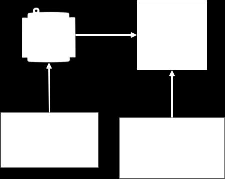
5 Functional Block Diagram Subsystems Drive System 3. Control 4. Test 5

6 CONOPS Overview Manufacturing Control Testing/ Schedule Budget 6

7 Current Schedule 7
8 Current Schedule 8
9 Manufacturing - Overview What is included: Housing Gears Driveshaft Bearings Seals Assembly Helium Regulator Holster Overview Manufacturing Control Testing/ Schedule Budget 9
10 Manufacturing Gear pump is made up of: Gears To be Manufactured Housing To be Manufactured Close-out panel To be Manufactured Driveshaft To be finalized, will be keyed and altered Alignment Shaft To be finalized, will be keyed and altered Seals Purchased; Geometry is being triple checked Main bearings Purchased; Thrust and roller bearings to be purchased Coupler To be Purchased Collar To be Purchased Overview Manufacturing Control Testing/ Schedule Budget 10

11 Gears Wire EDM profile with ground faces Finalizing stock requirements (17-4 PH Stainless) CFD results may dictate minor changes No post machining with decided manufacturer Delivery 4 weeks ARO Overview Manufacturing Control Testing/ Schedule Budget 11
12 Housing CNC here at CU, use a rough cut first to minimize time on CNC Benefit working from our model Based off of continued CFD results, a second housing with looser tolerances may be made perhaps here or at SAS This gives us a back up Must continue to move forward and complete CFD concurrently Time frame: 4 weeks Concerns: Depth of extruded cut, maintaining the profile, materials, special tools to manufacture Overview Manufacturing Control Testing/ Schedule Budget 12

13 Housing Overview Manufacturing Control Testing/ Schedule Budget 13
14 Close-Out Plate CNC here at CU Based off of continued CFD results, a second housing with looser tolerances may be made perhaps here or at SAS This gives us a back up, singular plate may work for both housings TBD Time frame: 4 weeks lead time Drawing to be finalized: still awaiting relief grooves, seal groove geometry may change for optimal performance Concerns: material, special tools to manufacture, rotary shaft seal and geometry Overview Manufacturing Control Testing/ Schedule Budget 14


15 Close-Out Plate Overview Manufacturing Control Testing/ Schedule Budget 15
16 Manufacturing Seals 1 large O-ring for faceplate and housing 1 O-ring shaft seal Groove geometry is being triple checked; May utilize a double seal Ready for pick-up in Denver Bearings Bearing manufacturer that commonly supplies bearings for gear pumps is sending 'samples' for free (shipped, awaiting arrival) This is putting constraints on our shafts metric options may solve this Thrust bearings are outside of working fluid and work with a collar to retain the drive shaft Roller bearings are included to avoid wear on the inside of the housing and necessitate post-machining of the shafts Overview Manufacturing Control Testing/ Schedule Budget 16
17 Manufacturing Driveshaft and placement Post-machine here We can key in the shop here, allows for proper contact and sizing to maintain integrity of housing Metric options are being explored to obtain proper undersizing for the performancing sleeve bearings Timeframe: 20 hours Overview Manufacturing Control Testing/ Schedule Budget 17
18 Overall Timeframe Seal groove geometry will be finalized by Tuesday COB Meeting with Matt Rhode Tuesday to nail down logistics proper material and special tools Order and get materials and tools by Feb. 13th Start machining ASAP Feb 13th or 14th Overview Manufacturing Control Testing/ Schedule Budget 18
19 Assembly Gear Drive Shaft Gap Detected Gear Setup Shim Gear Spacing Shim Shaft Bearing Bearing Spacer 19
20 Assembly Gear Drive Shaft Spacing Verified Gear Setup Shim Gear Spacing Shim (+.0005) Shaft Bearing Bearing Spacer 20
21 Assembly Gear Drive Shaft Gear Setup Shim Gear Spacing Shim (+.0005) Shaft Bearing Bearing Spacer 21
22 Assembly Gear Drive Shaft Key Drive Shaft Spacing Verified Gear Spacing Shim (+.0005) Shaft Bearing Bearing Spacer Timeframe: 1 week for assembly 22
23 Assembly Shaft Thrust Bearing Collar Closeout Plate Seal Bearing Timeframe: 1 week for assembly 23
24 Electronic He Regulator Constructing an Electronic Helium Regulator To control the drive system Manufacture a holster to house the stepper motor Timeframe: 80 hours Overview Manufacturing Control Testing/ Schedule Budget 24

25 Electronic He Regulator Solenoid regulator was too expensive Manufacturing from aluminum Houses stepper motor Need 8 Nm of torque to turn the pressure regulator at its lowest settings Similar setup for back pressure regulator Overview Manufacturing Control Testing/ Schedule Budget 25


26 Electronics FBD All electronic design falls in here 26
27 Electronics Signal Conditioning Design will be tested in a breadboard PCB board will be designed based on the breadboard PCB board will be populated Testing Component testing will be done on the breadboard Integration will be done with the PCB board Overview Manufacturing Testing/ Budget Control Schedule 27
28 Electronics Integration Electronics Sensors DAQs NI 9211 (temperature readings) NI 9205 (pressure readings, similar to NI 6002 but more powerful) will use NI 6002 for final tests 100 hours left for all testing and integration Overview Manufacturing Testing/ Budget Control Schedule 28
29 Software Software LabVIEW Development order: File system - complete Component tests/daq system in progress (~10 hours, <1 week) Control systems model, simulate, implement in progress (~45 hours, 4 weeks) Full system tests - TBD (~60 hours, 5 weeks) DAQ Software Drivers Already have Post test analysis - MATLAB (file read functions complete) Overview Manufacturing Testing/ Budget Control Schedule 29
30 Control code overview: Safety implicit to error check Throttle manual or automatic Backpressure faster than power - prevent oscillation Software Overview Manufacturing Control Testing/ Schedule Budget 30
31 Pressure valve control: Some data kept in memory check valve position Software Overview Manufacturing Control Testing/ Schedule Budget 31
32 Backpressure control: Fastest control component Software Overview Manufacturing Control Testing/ Schedule Budget 32

33 Software Software thermocouple test block diagram Overview Manufacturing Testing/ Budget Control Schedule 33

34 Software Software thermocouple test user interface Overview Manufacturing Testing/ Budget Control Schedule 34

35 Software Combined pressure and temperature user interface 115 hours remain Overview Manufacturing Testing/ Budget Control Schedule 35
36 Piping Assembly Low Pressure ~ 50PSI High Pressure ~ 750PSI Nomenclature Water Pipe Size: ¾"NPT Pressure Ranges: PSI Max Flow Rate: 22Gal/min Air Pipe Size: 1"NPT Pressure Ranges: PSI Max Flow Rate: 45CFM High Pressure ~ up to 2200 PSI Medium Pressure ~ up to 125PSI Regulated Pressure ~ 0-125PSI SV = Solenoid Valve RV = Relief Valve MBV = Manual Ball Valve MR = Manual Regulator EP = Electronic Pressure Regulator BPR = Back Pressure Regulator TM = Tachometer BD = Burst Disk LB = Lubricator F = Air Filter P = Pressure Transducer T = Temperature Sensor ADPT = GHT to NPT FP = Flexible Pipe QD = Quick Disconnect Overview Manufacturing Control Testing/ Schedule Budget 36
37 Testing Timeline Component Testing QC and Calibration Component Testing to be Conducted Man Hours Status Pressure Transducer (Air P1, Water P1) Air Pressure Regulator (EPR) Water Back Pressure Regulator (BPR) Thermocouples (T1, T2) Calibration through ranges of known shop air pressures Operation through 0-110PSI to calibrate outlet pressure/thread engagement Operation through 0-750PSI to calibrate inlet pressure/thread engagement Calibration at known temperatures (Ice bath, boiling ) 6 Hours : 1.5*(2*1 + 2*1 + 2*1) 50% 10.5 Hours : 3*1 + 3* *1 0% 10.5 Hours : 3*1 + 3* *1 0% 4 Hours : 2* *1 + 2* % Manual Ball Valve (Water MBV1) Verify correct operation (on/off) and no leaking 25 Minutes : 1* * *0.2 0% Solenoid Valve (Water SV1, Air SV2) Correct opening and closing upon energization and de-energization 1.5 Hours : 2* * *0.5 0% Tachometer Calibration at known RPMs 6 Hours : 2*1 + 2*1 + 2*1 0% Manual Air Regulator (MR1) Full Air Assembly Calibration to ranges with known shop air pressures Torque RPM, conducted with friction test, fan test 7 Hours : 2* *1 + 2*1 0% 13.5 Hours : 3*2 + 3* *1 0% Timing Personnel: Operators required Hours: Time required to prepare and assemble test Hours: Time required to conduct test Hours: Time required to disassemble test and save results Multiplier: Repeat test for identical sensor /component *Subsystem Testing included in backups Total Man Hours: Overview Manufacturing Testing/ Budget Control Schedule 37
38 Scope Electrical Software Manufacturing Create Signal Conditioning on Breadboard Develop a PCB Board Populate the PCB Board Component test Control systems System test Valving/Piping Housing Driveshaft Gears Bearings/Seals Integration 38


39 Budget Overview Manufacturing Testing/ Budget Control Schedule 39

40 Budget Overview Manufacturing Testing/ Budget Control Schedule 40

41 Schedule 41
42 Conclusions We are slightly behind schedule (3 days 1 week) Encountered problems with pump manufacturing Air motor testing Unable to find cheaper parts resulted in manufacturing them Increase in team hours to accomplish sensor and integration tasks Moving Forward: Increase in sub-component testing from all team members Timeframe: ~100 hours for Electronics ~200 hours for Software ~100 hours for Manufacturing/Assembly ~150 hours for Testing 42
43 Questions? 43
44 Backup 44

45 Housing Worries about shafts wearing into the housing necessitated this solution Possible to post machine down the ends to press fit into bearings and key in the proper locations for the gears and coupler
46 To prevent pressure pushing the driveshaft out, an extra retention method was included to prevent axial pushback since the shaft is essentially wedged between the mounted pump and mounted motor on the stand Housing
47 Seals The geometry is being updated to optimal specs. Will be finalized/double checked by COB Tuesday May included a double seal to mitigate possible leaking as we enter testing

48 Prelim Housing Drawing with GD&T

49 Prelim Close-out Panel Drawing with GD&T

50 Control - Software Pressure and temperature combined test setup Overview Manufacturing Control Testing/ Schedule Budget 50

51 Control - Software Pressure and temperature combined test main loop Overview Manufacturing Control Testing/ Schedule Budget 51
52 Phase 1 Sensor Testing and Simulation Electronic pressure regulator design Sensor Testing Simulink Modeling LabView Design Designing motor-regulator mechanical interface Designing pressure regulation through control of motor voltage Circuit Design: Power requirements, reading outputs Calibration: sampling rate, noise compensation, error rejection Model Drive and system Design control law for throttling pump flow rate Design realistic throttle profiles System circuit design Implementation of safety monitoring software Key Results to obtained Completion of pressure regulating system, obtaining resulting accuracy, slew rate, power requirements Pressure Transducer performance Tachometer mounting and performance First iteration of electronics circuit design First iteration of system control law Estimate of system slew rate (startup and shutdown) Generation of various throttle profiles First iteration of DAQ design for both data acquisition and system control First iteration of system user interface Design of system monitoring software Confirming testing location Phase 2 Functional Reqs. met None
53 Phase 2 Subsystem Testing Drive System Testing Motor: RPM/Torque Test Motor: Helium Run Test Manual Regulator: Pressure Fluctuations Electronic Regulator: Calibration to hit maximum accuracy. Tachometer: Calibration to hit maximum accuracy Power-Off testing: Verifying that solenoid valve correctly closes in case of power loss. Throttling Test 1: Throttling from % using the electronic pressure regulator, confirming control with pressure transducer. Throttling Test 2: Fully assembling drive system components. Running through throttle profiles. System Testing Manual Regulator: Pressure Fluctuations Power-Off testing: Verifying that solenoid valve correctly closes in case of power loss. Electronic Back Pressure Regulator: Calibration to hit maximum accuracy Key Results to be obtained Numerous iterations of throttling control software, monitoring software and electronic regulator software Assessment of unforeseen issues, correction of affected components Validation of component capabilities, allowing for full system assembly to occur Phase 2 Functional Reqs. met FR6, FR7
54 Piping Assembly Low Pressure ~ 50PSI High Pressure ~ 750PSI Nomenclature Water Pipe Size: ¾"NPT Pressure Ranges: PSI Max Flow Rate: 22Gal/min Air Pipe Size: 1"NPT Pressure Ranges: PSI Max Flow Rate: 45CFM High Pressure ~ up to 2200 PSI Medium Pressure ~ up to 125PSI Regulated Pressure ~ 0-125PSI SV = Solenoid Valve RV = Relief Valve MBV = Manual Ball Valve MR = Manual Regulator EP = Electronic Pressure Regulator BPR = Back Pressure Regulator TM = Tachometer BD = Burst Disk LB = Lubricator F = Air Filter P = Pressure Transducer T = Temperature Sensor ADPT = GHT to NPT FP = Flexible Pipe QD = Quick Disconnect Overview Manufacturing Control Testing/ Schedule Budget 54
55 Subsystem Testing Timeline Water Testing Subsystem Testing Component(s) Testing to be Conducted Man Hours Status Solenoid Valve Shut-Off Adapter, Quick Disconnect, Flexible Pipe, Pressure Ducer Pre- pressure loss Simulate excessive pressure and/or temperature readings to initiate safety shutdown Quantify pressure losses (water) associated with pre-piping assembly Quantify pressure loss (water) of full assembly leading to pump inlet 9 Hours : (2*4 + 2* *0.5) 0% 7.5 Hours : 2*1 + 2* *1 0% 10.5 Hours : 3*2 + 3* *1 0% Total Man Hours: 27 Timing Personnel: Operators required Hours: Time required to prepare and assemble test Hours: Time required to conduct test Hours: Time required to disassemble test and save results Multiplier: Repeat test for identical sensor /component Overview Manufacturing Control Testing/ Schedule Budget 55
56 Subsystem Testing Timeline Air Testing Subsystem Testing Component(s) Testing to be Conducted Man Hours Status Solenoid Valve Shut-Off Pressurized Gas, Manual Regulator, Solenoid Valve (Air), Relief Valve, Filter, Pressure Transducer Full air system excluding Air Motor Simulate excessive pressure and/or temperature readings to initiate safety shutdown Quantify pressure losses (air) associated with pre-regulator assembly Detection of pressure regulator misscalibration/erroneous operation 4 Hours : (2*1 + 2* *0.5) 0% 10.5 Hours : 3* *1+ 3*1 0% 13.5 Hours : 3*2 + 3*1 + 3*1.5 0% Total Man Hours: 28 Timing Personnel: Operators required Hours: Time required to prepare and assemble test Hours: Time required to conduct test Hours: Time required to disassemble test and save results Multiplier: Repeat test for identical sensor /component Overview Manufacturing Control Testing/ Schedule Budget 56
57 Subsystem Testing Timeline Air Testing Subsystem Testing Component(s) Testing to be Conducted Man Hours Status Solenoid Valve Shut-Off Pressurized Gas, Manual Regulator, Solenoid Valve (Air), Relief Valve, Filter, Pressure Transducer Full air system excluding Air Motor Full Air Assembly, air motor connected to friction assembly Simulate excessive pressure and/or temperature readings to initiate safety shutdown Quantify pressure losses (air) associated with pre-regulator assembly Detection of pressure regulator misscalibration/erroneous operation 9 Hours : (2*4 + 2* *0.5) 0% 7.5 Hours : 2*1 + 2* *1 0% 10.5 Hours : 3*2 + 3* *1 0% Total Man Hours: 27 Timing Personnel: Operators required Hours: Time required to prepare and assemble test Hours: Time required to conduct test Hours: Time required to disassemble test and save results Multiplier: Repeat test for identical sensor /component Overview Manufacturing Control Testing/ Schedule Budget 57
58 Phase 3 Full System Testing Full scale testing to be conducted Drive Shaft Alignment Mass flow rate testing Throttle profile testing System startup and shutdown testing Emergency shutdown testing Restartability testing Key Results to be obtained Determination of any misalignment of motor/pump driveshaft performance: mass flow rate, back pressure, efficiency Observation of system under numerous throttle profiles Iteration on shutdown procedures to optimize restartability Iteration on control law to account for unaccounted system properties
59 Final Testing Full scale testing to be conducted Throttle profile testing: (10-100% Throttle), slew rate testing. Quantifying magnitude of outlet pressure fluctuations Throttle profile testing (ran through various profiles) System startup and shutdown testing, with emergency shutdown and restart-ability Key Results to be obtained performance: mass flow rate, back pressure, efficiency Observation of system under numerous throttle profiles Iteration on shutdown procedures to optimize re-startability Iteration on control law to account for unaccounted system properties
60 Standard Testing Procedure - Example Throttle Calibration Test 1. is started up and commanded to throttle setting 2. The pump is run at throttle setting 3. Flow enters control volume for 10 secs 4. Flow is diverted back to regular vent 5. is shutdown 6. Control volume is measured and recorded 7. Test is re-iterated as needed for other throttle settings Critical Test Elements -Drive system Control Volume Flow Bypass system 3 Team membersmonitoring test Key Results to be obtained Validation of throttle model design Refinement of throttle model design Meeting of critical project element


61 Safety Set-Up Worst Case Failures 1. Drive system flywheel 225 J 2. Drive system casing 16 J 3. gears 36 J Cinder Block Housing Strength Chipping J Cracking J Penetration J Failure J Complete destruction - >1300 J

62 Analog to Digital Conversions Converting from ADC to pressure Find the MSMT out of the ADC to get the Voltage into the ADC Find the pressure out of the Pressure transducer Find pressure by dividing it by the voltage per pressure ratio
63 Automatic Pressure Regulator Electronic pressure regulators with high volume flow are not found, but manual do exists Combining a manual pressure regulator with an encoder and stepper motor Motor shall have a minimum angular velocity of 300 RPM No error, and time of settle of less than 1 second

64 Automatic Pressure Regulator FBD Controlling a stepper motor based on the position This position will allow the output pressure


65 Automatic Pressure Regulator Diagram Control points of view for the pressure regulator Can be simplified by combining both plants Needs to be tested to find the correlation of angular position with output RPM

66 Automatic Pressure Regulator This can be simplified by combining the drive system transfer function and the motor transfer function

67 Automatic Pressure Regulator Simplified version of the model Allows to control the drive system based on the voltage input
68 Signal Processing Differential Amplifier Use for creating an offset and applying a gain to the voltage out of the pressure transducer This will allow us to look at a range from psi a with higher accuracy.

69 Signal Processing Voltage divider Being able to from 28 V to.6 V The output will be used to provide the offset needed for V1
70 Signal Processing Noise Mitigation Low pass filter Easy to make First order filter Only one pole Vs Sallen-key filter Harder to make Second order filter Two poles

71 Signal Processing Noise Mitigation Prevents to look at high frequencies that are irrelevant This will have a cutoff frequency at 2 khz

72 Signal Processing Electronic diagram

73 Electronic Test
Hydraulic Proportional and Closed Loop System Design
 Hydraulic Proportional and Closed Loop System Design Neal Hanson Product Manager Industrial Valves and Electrohydraulics 1 Electrohydraulics Contents 1. Electrohydraulic Principles 2. Proportional Valve
COMET: Colorado Mini Engine Team Manufacturing Status Review February 3, 2014
 COMET: Colorado Mini Engine Team Status Review February 3, 2014 Team members: Julia Contreras-Garcia Emily Ehrle Eric James Jonathan Lumpkin Matthew McClain Megan O Sullivan Benjamin Woeste Kevin Wong
three different ways, so it is important to be aware of how flow is to be specified
 Flow-control valves Flow-control valves include simple s to sophisticated closed-loop electrohydraulic valves that automatically adjust to variations in pressure and temperature. The purpose of flow control
RIT Formula SAE Senior Design
 RIT Formula SAE Senior Design Agenda Project Description Work Breakdown Customer Needs Customer Specifications Current/Previous System Design Proposed Design #1 Proposed Design #2 Testing Plans Concept
Understanding the benefits of using a digital valve controller. Mark Buzzell Business Manager, Metso Flow Control
 Understanding the benefits of using a digital valve controller Mark Buzzell Business Manager, Metso Flow Control Evolution of Valve Positioners Digital (Next Generation) Digital (First Generation) Analog
University of Colorado Model Positioning - DynAmic/Static - System. Preliminary Design Review 13 October 2015
 University of Colorado Model Positioning - DynAmic/Static - System Preliminary Design Review 13 October 2015 Nicholas Gilland, Brandon Harris, Kristian Kates, Ryan Matheson, Amanda Olguin, Kyle Skjerven,
EE 370L Controls Laboratory. Laboratory Exercise #E1 Motor Control
 1. Learning Objectives EE 370L Controls Laboratory Laboratory Exercise #E1 Motor Control Department of Electrical and Computer Engineering University of Nevada, at Las Vegas To demonstrate the concept
TECHNICAL PAPER 1002 FT. WORTH, TEXAS REPORT X ORDER
 I. REFERENCE: 1 30 [1] Snow Engineering Co. Drawing 80504 Sheet 21, Hydraulic Schematic [2] Snow Engineering Co. Drawing 60445, Sheet 21 Control Logic Flow Chart [3] Snow Engineering Co. Drawing 80577,
Test Plans & Test Results
 P09310 Automatic Shift Controls for ATV Test Plans & Test Results By: Ashley Shoum, Matt Dombovy-Johnson, Keith Cobb, Jon Willistein, Feng Li, Bibhu Shah, Sarah Bicho Table of contents MSD I: WKS 8-10
Test Plans & Test Results
 P10227 Variable Intake System for FSAE Race Car Test Plans & Test Results By: Dave Donohue, Dan Swank, Matt Smith, Kursten O'Neill, Tom Giuffre Table of contents 1. MSD I: WKS 8-10 PRELIMINARY TEST PLAN...
EEL Project Design Report: Automated Rev Matcher. January 28 th, 2008
 Brad Atherton, masscles@ufl.edu, 352.262.7006 Monique Mennis, moniki@ufl.edu, 305.215.2330 EEL 4914 Project Design Report: Automated Rev Matcher January 28 th, 2008 Project Abstract Our device will minimize
Detailed Design Review
 Detailed Design Review Reciprocating Friction Tester : Armature Subsystem Thursday December 4th, 2014 1 : Armature Subsystem Eric Kutil (ME): Project Manager Specialty: Solid Modeling and Machining Chris
Series 1780 Dynamometer V2 Datasheet
 Series 1780 Dynamometer V2 Datasheet Typical use Outrunner brushless motor characterization 25 kgf / 0-100 A 40 kgf / 0-150 A (Plus) Propeller characterization up to 47 Servo testing and control Battery
stage from resolution accuracies is 400 peak) and the from an to outpu positioning (as shown N] continuous continuous needs
![stage from resolution accuracies is 400 peak) and the from an to outpu positioning (as shown N] continuous continuous needs](/thumbs/80/81553844.jpg "stage from resolution accuracies is 400 peak) and the from an to outpu positioning (as shown N] continuous continuous needs") Earthquake Simulation Using Single or Dual-Axis Linear Motion Stages With the goal of safer buildings and saving lives, scientists and engineers, through the simulation of many recent earthquakes, need
Earthquake Simulation Using Single or Dual-Axis Linear Motion Stages With the goal of safer buildings and saving lives, scientists and engineers, through the simulation of many recent earthquakes, need
User Manual. Aarhus University School of Engineering. Windtunnel Balance
 Aarhus University School of Engineering Windtunnel Balance User Manual Author: Christian Elkjær-Holm Jens Brix Christensen Jesper Borchsenius Seegert Mikkel Kiilerich Østerlund Tor Dam Eskildsen Supervisor:
Compatibility of STPA with GM System Safety Engineering Process. Padma Sundaram Dave Hartfelder
 Compatibility of STPA with GM System Safety Engineering Process Padma Sundaram Dave Hartfelder Table of Contents Introduction GM System Safety Engineering Process Overview Experience with STPA Evaluation
Building and Validating a Rotational Viscometer
 Building and Validating a Rotational Viscometer Brian Cherrington & Jack Rothstein Mechanical Engineering Faculty Mentors: Dr. Maria-Isabel Carnasciali, Dr. Samuel Daniels Abstract This project was an
Cartridge Valve and Manifold Technologies
 Energy Efficient Hydraulics and Pneumatics Conference Cartridge Valve and Manifold Technologies A Components Approach to Improved Energy Efficiency How Can Components Lead to Greater Energy Efficiency?
Test Plans & Test Results
 Table of contents P09222 FSAE ECU Gen III Test Plans & Test Results By: Andrew Rittase, Robert Joslyn, Dereck Bojanowski, Robert Raymond, Giovanni Sorrentino, Jordan Hibbits 1. MSD I: WKS 8-10 TEST PLAN...
Vehicle Diagnostic Logging Device
 UCCS SENIOR DESIGN Vehicle Diagnostic Logging Device Design Requirements Specification Prepared by Mackenzie Lowrance, Nick Hermanson, and Whitney Watson Sponsor: Tyson Hartshorn with New Planet Technologies
Operation and Maintenance Manual
 BM / BMA Hydrometers ½ Operation and Maintenance Manual i This manual is intended for use by the users of this equipment. The information contained herein is the property of the Arad Ltd. Dalia and may
Centerwide System Level Procedure
 5.ARC.0004.2 1 of 10 REVISION HISTORY REV Description of Change Author Effective Date 0 Initial Release J. Hanratty 7/17/98 1 Clarifications based on 7/98 DNV Audit and 6/98 Internal Audit (see DCR 98-029).
Beyond Standard. Dynamic Wheel Endurance Tester. Caster Concepts, Inc. Introduction: General Capabilities: Written By: Dr.
 Dynamic Wheel Endurance Tester Caster Concepts, Inc. Written By: Dr. Elmer Lee Introduction: This paper details the functionality and specifications of the Dynamic Wheel Endurance Tester (DWET) developed
High Level Design ElecTrek
 High Level Design ElecTrek EE Senior Design November 9, 2010 Katie Heinzen Kathryn Lentini Neal Venditto Nicole Wehner Table of Contents 1 Introduction...3 2 Problem Statement and Proposed Solution...3
Product Loss During Retail Motor Fuel Dispenser Inspection
 Product Loss During Retail Motor Fuel Dispenser Inspection By: Christian Lachance, P. Eng. Senior Engineer - ment Engineering and Laboratory Services ment Canada Date: Product Loss During Retail Motor
6.0 SPECIFICATIONS CONTENTS. Calibration. According to factory procedureeeeeeeeeeeeeee Accuracy*
 6.0 SPECIFICATIONS Calibration According to factory procedureeeeeeeeeeeeeee Accuracy* ± 1% full scale (FS) or ± 1 graduation on scale Scale diameter 41 mm Temperature range 45 to 115 F (10-45 C) Air humidity
MSD: Case Studies D R. T A R E K A. T U T U N J I P H I L A D E L P H I A U N I V E R S I T Y, J O R D A N
 MSD: Case Studies D R. T A R E K A. T U T U N J I P H I L A D E L P H I A U N I V E R S I T Y, J O R D A N 2 0 1 4 Outline Elements and design of mechatronic systems have been described in previous sections
Test Which component has the highest Energy Density? A. Accumulator. B. Battery. C. Capacitor. D. Spring.
 Test 1 1. Which statement is True? A. Pneumatic systems are more suitable than hydraulic systems to drive powerful machines. B. Mechanical systems transfer energy for longer distances than hydraulic systems.
Automated Seat Belt Switch Defect Detector
 pp. 10-16 Krishi Sanskriti Publications http://www.krishisanskriti.org/publication.html Automated Seat Belt Switch Defect Detector Department of Electrical and Computer Engineering, Sri Lanka Institute
NEW MEXICO STATE UNIVERSITY
 Fall 2011 [HYBRID ROCKET TEAM] NEW MEXICO STATE UNIVERSITY Portable hybrid rocket motors and test stands can be seen in many papers, but none have been reported on the design or instrumentation at such
The Latest Sensor Trends
 Sensing & Feedback Technologies The Latest Sensor Trends Agenda Miniature sensors open up new applications Alternatives to Fiber optics Pneumatic cylinder sensing: Dual systems, analog and lifetime warranties
DATUM ELECTRONICS RS425 NON-CONTACT TORQUE TRANSDUCER PRODUCT OVERVIEW
 DATUM ELECTRONICS LIMITED TELEPHONE: +44 (0) 1983 28 28 34 FAX: +44 (0) 1983 28 28 35 EMAIL: support@datum-electronics.co.uk WEB: www.datum-electronics.co.uk DATUM ELECTRONICS RS425 NON-CONTACT TORQUE
Implementation of a Grid Connected Solar Inverter with Maximum Power Point Tracking
 ECE 4600 GROUP DESIGN PROJECT PROGRESS REPORT GROUP 03 Implementation of a Grid Connected Solar Inverter with Maximum Power Point Tracking Authors Radeon Shamilov Kresta Zumel Valeria Pevtsov Reza Fazel-Darbandi
ATX165SL/SLE Series Mechanical-Bearing, Screw-Driven Linear Stage
 ATX165SL/SLE Series Mechanical-Bearing, Screw-Driven Linear Stage Travel lengths up to 250 mm with anti-creep crossed-roller bearings Optional center-mounted linear encoder for direct position feedback
DESIGN AND EXPERIMENTATION OF TEST RIG TO CHARACTERIZE HYDROSTATIC DRIVEFOR LINEAR ACTUATOR
 DESIGN AND EXPERIMENTATION OF TEST RIG TO CHARACTERIZE HYDROSTATIC DRIVEFOR LINEAR ACTUATOR Sherif Elbaz 1, Moatasem 2, Ibrahim 3, Nabila 4, Mohamed 5 1 Automotive Engineering Department, Ain-Shames University,
Measuring equipment for the development of efficient drive trains using sensor telemetry in the 200 C range
 News Measuring equipment for the development of efficient drive trains using sensor telemetry in the 200 C range Whether on the test stand or on the road MANNER Sensortelemetrie, the expert for contactless
Robot Arm with Conveyor Belts
 Robot Arm with Conveyor Belts This example models a robotic arm and two conveyor belts. One conveyor belts bring blocks to the robot. The robot grabs the block, flips it over and transfers it to another
IntelliMold Systems OEM Integration: Van Dorn Revision Level: 002 Document Number:
 IntelliMold Systems OEM Integration: Van Dorn Revision Level: 002 Document Number: 7.5.1.0.30.002 The following information is for reference only. It is subject to change and may not be identical on all
Fiat - Argentina - Wheel Aligner / Headlamp Aimer #16435
 2017 Fiat - Argentina - Wheel Aligner / Headlamp Aimer #16435 Wheel Aligner / Headlamp Aimer Operation & Maintenance Manual Overview Fori Automation Version 1.2 4/21/2017 TABLE OF CONTENTS Section 1.0
SAE Mini BAJA: Suspension and Steering
 SAE Mini BAJA: Suspension and Steering By Zane Cross, Kyle Egan, Nick Garry, Trevor Hochhaus Team 11 Progress Report Submitted towards partial fulfillment of the requirements for Mechanical Engineering
Hydrogen Station Equipment Performance Device (HyStEP Device) Specification
 Specification") Hydrogen Station Equipment Performance Device (HyStEP Device) Specification Overview Policies and technology solutions need to be developed and implemented to help reduce the time from when a new hydrogen
Hydrogen Station Equipment Performance Device (HyStEP Device) Specification Overview Policies and technology solutions need to be developed and implemented to help reduce the time from when a new hydrogen
FUNCTIONAL SAFETY SOLUTIONS in Solenoid Valves
 FUNCTIONAL SAFETY SOLUTIONS in Solenoid Valves Safety is reality and is part of our daily business. The same applies to ASCO; it is reality and part of your safety. You can rely on our focus on reliable
MicroGuard 586 Retrofit Rated Capacity Indicator System. Calibration and Testing for:
 GREER COMPANY Page 1 of 22 MicroGuard 586 Retrofit Rated Capacity Indicator System Machine Model Serial Number Tester Date Calibration and Testing for: GREER COMPANY Page 2 of 22 MicroGuard 586 Retrofit
Open Center Compact Valve Custom Installation Guide Rev A
 200-0762-01 Open Center Compact Valve Custom Installation Guide 602-0575-01 Rev A 2014-12 Overview This guide provides information for completing a custom AutoSteer valve installation on wheeled farm vehicles
RETROFIT OF A ROLLER BRAKE TESTER AT FAMENA
 Mladen Božić Ante Vučetić Petar Ilinčić Zoran Lulić ISSN 1333-1124 eissn 1849-1391 RETROFIT OF A ROLLER BRAKE TESTER AT FAMENA Summary UDC 629.3.017/018 The vehicle brake tester described in this paper
PRODUCT REQUIREMENTS
 Model 644 Technical Specifications Page 1 of 9 GAS TURBINE AND JET ENGINE COMPONENT TESTING Mass Airflow Test Stand PRODUCT REQUIREMENTS Multiple manufacturers in the Aerospace industry required Airflow
TurboGen TM Gas Turbine Electrical Generation System Sample Lab Experiment Procedure
 TurboGen TM Gas Turbine Electrical Generation System Sample Lab Experiment Procedure Lab Session #1: System Overview and Operation Purpose: To gain an understanding of the TurboGen TM Gas Turbine Electrical
Vibration damping precision couplings
 Vibration damping precision couplings In light of the advantages of elasticity, strength, resilience, and damping effects, elastomer materials are now being used in most areas of mechanical engineering.
Geareducer models
 USER MANUAL Geareducer models 2200-2250-2400 OPERATION - MAINTENANCE - REPAIR M99-1260E ISSUED 6/2012 READ AND UNDERSTAND THIS MANUAL PRIOR TO OPERATING OR SERVICING THIS PRODUCT. operation and service
The MathWorks Crossover to Model-Based Design
 The MathWorks Crossover to Model-Based Design The Ohio State University Kerem Koprubasi, Ph.D. Candidate Mechanical Engineering The 2008 Challenge X Competition Benefits of MathWorks Tools Model-based
How to: Test & Evaluate Motors in Your Application
 How to: Test & Evaluate Motors in Your Application Table of Contents 1 INTRODUCTION... 1 2 UNDERSTANDING THE APPLICATION INPUT... 1 2.1 Input Power... 2 2.2 Load & Speed... 3 2.2.1 Starting Torque... 3
Six keys to achieving better precision in linear motion control applications
 profile Drive & Control Six keys to achieving better precision in linear motion control applications Achieving precise linear motion Consider these factors when specifying linear motion systems: Equipped
GPM Hydraulic Flow Meter User Manual
 4278 100 GPM Hydraulic Flow Meter User Manual Introduction The OTC 4278 Hydraulic Flow Meter has been designed for easy connection to a hydraulic circuit so that flow, pressure and temperature can be readily
INSTRUCTION MANUAL CAT Bio-Pump Plus
 1 INSTRUCTION MANUAL CAT. 65211-12 Bio-Pump Plus 2 Introduction The Bio-Pump Plus is an advanced portable, battery-powered air sampling pump designed for the exclusive use with Air-O-Cell, Via-Cell and
Application Notes. Calculating Mechanical Power Requirements. P rot = T x W
 Application Notes Motor Calculations Calculating Mechanical Power Requirements Torque - Speed Curves Numerical Calculation Sample Calculation Thermal Calculations Motor Data Sheet Analysis Search Site
QuickStick Repeatability Analysis
 QuickStick Repeatability Analysis Purpose This application note presents the variables that can affect the repeatability of positioning using a QuickStick system. Introduction Repeatability and accuracy
PRODUCTS OVERVIEW. Linear Motion in its Simplest Form
 Linear Motion in its Simplest Form Simplicity of Design - IntelLiDrives TM produce direct linear motion, eliminating stretching belts, slipping pulleys, hysteresis and wear of the leadscrews. Cost Effective
VBK 2596/12E/RSF. Thickness and Width Gauge for Strip and Profile. Operating- & Service Instructions. (with lateral guide rollers)
") Thickness and Width Gauge for Strip and Profile (with lateral guide rollers) VBK 2596/12E/RSF Operating- & Service Instructions erstellt am 5.2.1998 freigegeben am Bemerkungen Rev.01 Seiten:16 Name: Rietdorf
Thickness and Width Gauge for Strip and Profile (with lateral guide rollers) VBK 2596/12E/RSF Operating- & Service Instructions erstellt am 5.2.1998 freigegeben am Bemerkungen Rev.01 Seiten:16 Name: Rietdorf
TABLE OF CONTENTS NOTES. 1.0 Operating principle... 02
 OI-001 NOTES TABLE OF CONTENTS 1.0 Operating principle.............................................. 02 2.0 Overview....................................................... 03 2.1 Operating elements 2.2
Familiarize yourself with the pressure loss phenomenon. The Discussion of this exercise covers the following point:
 Exercise 3-2 Pressure Loss EXERCISE OBJECTIVE Familiarize yourself with the pressure loss phenomenon. DISCUSSION OUTLINE The Discussion of this exercise covers the following point: Pressure loss Major
Fisher 657 Diaphragm Actuator Sizes and 87
 Instruction Manual 657 Actuator (30-70 and 87) Fisher 657 Diaphragm Actuator Sizes 30 70 and 87 Contents Introduction... 1 Scope of Manual... 1 Description... 2 Specifications... 2 Installation... 3 Mounting
BAS Construction Checklist
 BAS Construction Checklist Project: Building: Location: Submittal / Approvals Submittal. The above equipment and systems integral to them are complete and ready for functional testing. The checklist items
Servo Creel Development
 Servo Creel Development Owen Lu Electroimpact Inc. owenl@electroimpact.com Abstract This document summarizes the overall process of developing the servo tension control system (STCS) on the new generation
3388, 3588, 3788, 6388, 6588 & 6788 Volume 1 of 2
 International Harvester Service Manual 3388, 3588, 3788, 6388, 6588 & 6788 Volume 1 of 2 Service Manual THIS IS A MANUAL PRODUCED BY JENSALES INC. WITHOUT THE AUTHORIZATION OF INTERNATIONAL HARVESTER OR
NASA Glenn Research Center Intelligent Power System Control Development for Deep Space Exploration
 National Aeronautics and Space Administration NASA Glenn Research Center Intelligent Power System Control Development for Deep Space Exploration Anne M. McNelis NASA Glenn Research Center Presentation
DESCRIPTION AND OPERATION
 Page 1 of 10 DESCRIPTION AND OPERATION AIR DELIVERY DESCRIPTION AND OPERATION The air delivery description and operation is divided into five areas: HVAC Control Components Air Speed Air Delivery Recirculation
Upgrade your blow molding machine with one of our two new state of the art machine control systems.
 Upgrade your blow molding machine with one of our two new state of the art machine control systems. Uniloy is proud to introduce the Allen Bradley Compact Logix, and B&R Control Packages developed for
CP Data Sheet I-CAM Introduction: I-CAM, Integrated Calibration And Automated Mapping CP Engineering Systems Ltd.
 I-CAM Introduction: I-CAM, Integrated Calibration And Automated Mapping as a component add-on to the advanced CADET V12 Engine and Vehicle Test System, provides a state-of-the-art, automatic engine spark
TurboGen TM Gas Turbine Electrical Generation System Sample Lab Experiment Procedure
 TurboGen TM Gas Turbine Electrical Generation System Sample Lab Experiment Procedure Lab Session #1: System Overview and Operation Purpose: To gain an understanding of the TurboGen TM Gas Turbine Electrical
Ball Rail Systems RE / The Drive & Control Company
 Ball Rail Systems RE 82 202/2002-12 The Drive & Control Company Rexroth Linear Motion Technology Ball Rail Systems Roller Rail Systems Standard Ball Rail Systems Super Ball Rail Systems Ball Rail Systems
LEAD SCREWS 101 A BASIC GUIDE TO IMPLEMENTING A LEAD SCREW ASSEMBLY FOR ANY DESIGN
 LEAD SCREWS 101 A BASIC GUIDE TO IMPLEMENTING A LEAD SCREW ASSEMBLY FOR ANY DESIGN Released by: Keith Knight Kerk Products Division Haydon Kerk Motion Solutions Lead Screws 101: A Basic Guide to Implementing
PRSalpha Air Drill (Double Valve)
") 888-680-4466 ShopBotTools.com PRSalpha Air Drill (Double Valve) Copyright 2016 ShopBot Tools, Inc. page 1 Copyright 2016 ShopBot Tools, Inc. page 2 Table of Contents Overview...5 Spindle Mounting Plate...6
888-680-4466 ShopBotTools.com PRSalpha Air Drill (Double Valve) Copyright 2016 ShopBot Tools, Inc. page 1 Copyright 2016 ShopBot Tools, Inc. page 2 Table of Contents Overview...5 Spindle Mounting Plate...6
Component and System Level Modeling of a Two-Phase Cryogenic Propulsion System for Aerospace Applications
 Component and System Level Modeling of a Two-Phase Cryogenic Propulsion System for Aerospace Applications J. LoRusso, B. Kalina, M. Van Benschoten, Roush Industries GT Users Conference November 9, 2015
DMT PERFORMING UNDER PRESSURE DMT. Pressure Scanner Features. Applications. Description 1/7
 Features User Accessible Memory for Test Configuration Management ±0.05% FS System Accuracy EU Throughput Rates of 500 Hz Auto-Negotiating 10/100 BaseT Ethernet with TCP & UDP Protocol Pressure Ranges
Solar RC Boat 49. Team 5: Nisa Chuchawat, Robert Whalen, Zhendong Yang ECE 445 Project Proposal - Fall 2017 TA: Yamuna Phal
 Solar RC Boat 49 Team 5: Nisa Chuchawat, Robert Whalen, Zhendong Yang ECE 445 Project Proposal - Fall 2017 TA: Yamuna Phal 1 Introduction 1.1 Objective Typical RC boats have terrible battery life and long
Mini-Lab Gas Turbine Power System TM Sample Lab Experiment Manual
 Mini-Lab Gas Turbine Power System TM Sample Lab Experiment Manual Lab Session #1: System Overview and Operation Purpose: To gain an understanding of the Mini-Lab TM Gas Turbine Power System as a whole
DVFP Series Variable Frequency Drive - Product Manual. pg. 1
 pg. 1 Set Up Instructions for DVFP Inspect the packaging of the equipment to confirm that nothing was damaged during shipping. Remove the system from the packaging. Make sure everything is included and
Installation, Operation and Maintenance Manual
 Document 479288 Installation, Operation and Maintenance Manual Please read and save these instructions for future reference. Read carefully before attempting to assemble, install, operate or maintain the
Installation and Maintenance Instructions JSE MAEAD Extruder Clutch. World Leader in Modular Torque Limiters
 World Leader in Modular Torque Limiters Installation and Maintenance Instructions JSE.5-0104MAEAD Extruder Clutch 1304 Twin Oaks Street Wichita Falls, Texas 76302 (940) 723-7800 Fax: (940) 723-7888 E-mail:
GLAST Large Area Telescope:
 GLAST Large Area Telescope: Gamma-ray Large Area Space Telescope MGSE Integration Readiness Status Two Tower Operations Eric Gawehn SU-SLAC LAT I&T MGSE Dept. Manager egawehn@slac.stanford.edu 650 926
Page. 1.0 Overview & Operating Principle Operating Elements Quick Start Instructions Calibration Notes...
 NOTES CONTENTS 1.0 Overview & Operating Principle................................. 02 2.0 Operating Elements........................................... 03 3.0 Quick Start Instructions........................................
AMBR* Engine for Science Missions
 AMBR* Engine for Science Missions NASA In Space Propulsion Technology (ISPT) Program *Advanced Material Bipropellant Rocket (AMBR) April 2010 AMBR Status Information Outline Overview Objectives Benefits
UPGRADE YOUR BLOW MOLDING MACHINE WITH ONE OF OUR TWO NEW STATE OF THE ART MACHINE CONTROL SYSTEMS.
 UPGRADE YOUR BLOW MOLDING MACHINE WITH ONE OF OUR TWO NEW STATE OF THE ART MACHINE CONTROL SYSTEMS. Uniloy is proud to introduce the Allen Bradley Compact Logix, and B&R Control Packages developed for
Digital III Fueling Vehicle Control System
 SM64335-2 April 2005 Aerospace Group Conveyance Systems Division Carter Brand Ground Fueling Equipment Applicable additional manuals: SM64335-1 Setup & Calibration User s Manual Digital III Fueling Vehicle
Torque Measurement Primer
 Torque Measurement Primer 2/2010 Torque Primer V2 4/22/11 2 So you ve decided you need a torque transducer? Now comes the fun part choosing the right one. The following pages will point out some factors
liquid Pumps Air driven contents Chatsworth, California, USA LP500C
 LP5C Air driven liquid Pumps contents Principle of Operation, Features, Why Use Air Driven Pumps...2 Typical Applications...3 Model Selection Table...4 Type of Materials in Contact with Fluid, Liquid Compatibility
Magnetostrictive Actuator
 Magnetostrictive Actuator Project Proposal Randall Bateman, Aaron Bolyen, Chris Cleland Alex Lerma, Xavier Petty, Michael Roper December 11, 2015 Overview Introduction Need Statement/Goals Constraints
Designing Drive Systems for Low Web Speeds
 Designing Drive Systems for Low Web Speeds Web Tension Control at Low Speeds Very low web speeds can provide challenges to implementing drive systems with accurate tension control. UNWIND LOAD CELL COOLING
DACON INSEPECTION SERVICES CORROSION UNDER SUPPORT
 DACON INSEPECTION SERVICES CORROSION UNDER SUPPORT Who we are Conventional and Advanced NDT and Inspection Services Oil and Gas, Refinery, Petrochemical, Heavy Industry, Mining Over 400 personnel including
Thermo Scientific APEX 500 Rx Metal Detector User s Guide. REC 4345 Rev B Part number English
 Thermo Scientific APEX 500 Rx Metal Detector User s Guide REC 4345 Rev B Part number 109541 English 2010 Thermo Fisher Scientific, Inc. All rights reserved For future reference, write your APEX 500 Rx
MultiCam 3000 Series CNC Router Feature and Specification Guide. Versatile, Feature-Rich Production Routing! The MultiCam. Ideal for Cutting: Wood
 MultiCam 3000 Series CNC Router Feature and Specification Guide Versatile, Feature-Rich Production Routing! The MultiCam 3000 Series CNC Routers are loaded with standard features normally associated with
Reciprocating Compressor Installation and Validation
 Reciprocating Compressor Installation and Validation MSD II - 11452 John Blamer (ME) Team Leader Promit Bagchi (ME) Lead Engineer Elliot Kendall (ME) Hydronics Engineer Matthias Purvis (ME) Operations
Influence of Cylinder Bore Volume on Pressure Pulsations in a Hermetic Reciprocating Compressor
 Purdue University Purdue e-pubs International Compressor Engineering Conference School of Mechanical Engineering 2014 Influence of Cylinder Bore Volume on Pressure Pulsations in a Hermetic Reciprocating
Engine Management and Data Acquisition Systems
 Engine Management and Data Acquisition Systems In 2013 FuelTech celebrates ten years of innovative success and, although young, it has become a synonym of quality high performance. The company was created
University Of California, Berkeley Department of Mechanical Engineering. ME 131 Vehicle Dynamics & Control (4 units)
") CATALOG DESCRIPTION University Of California, Berkeley Department of Mechanical Engineering ME 131 Vehicle Dynamics & Control (4 units) Undergraduate Elective Syllabus Physical understanding of automotive
CATALOG DESCRIPTION University Of California, Berkeley Department of Mechanical Engineering ME 131 Vehicle Dynamics & Control (4 units) Undergraduate Elective Syllabus Physical understanding of automotive
Boston Gear LOR Series
 Boston Gear LOR Series Trig-O-Matic Lite Overload Release Clutch Installation and Maintenance Instructions Doc. No. LOR Series Trig-O-Matic Lite www.bostongear.com LOR SERIES TRIG-O-MATIC LITE OVERLOAD
Introduction to hmtechnology
 Introduction to hmtechnology Today's motion applications are requiring more precise control of both speed and position. The requirement for more complex move profiles is leading to a change from pneumatic
Optimizing Battery Accuracy for EVs and HEVs
 Optimizing Battery Accuracy for EVs and HEVs Introduction Automotive battery management system (BMS) technology has advanced considerably over the last decade. Today, several multi-cell balancing (MCB)
Date Author(s) Change(s) Status
 Change(s) Status") Plasma Control Technologies Service Bulletin-60 Overview Integrated Drive Document history Doc. Rev. Date Author(s) Change(s) Status 1.0 2007-03-30 O. Lehmann Initial document released 1.1 2010-06-25 A.
Plasma Control Technologies Service Bulletin-60 Overview Integrated Drive Document history Doc. Rev. Date Author(s) Change(s) Status 1.0 2007-03-30 O. Lehmann Initial document released 1.1 2010-06-25 A.
Section 3 Technical Information
 Section 3 Technical Information In this Module: Engine identification Modes of operation Battery charging and heat manage operation Service and repair procedures Maintenance requirements Engine Identification