DVFP Series Variable Frequency Drive - Product Manual. pg. 1
|
|
|
- Brent Simmons
- 5 years ago
- Views:
Transcription

1 pg. 1

2 Set Up Instructions for DVFP Inspect the packaging of the equipment to confirm that nothing was damaged during shipping. Remove the system from the packaging. Make sure everything is included and without damage. Below is a checklist with everything you should have received. The system will already be assembled and should arrive in one piece. 1) Pump (Figure 1) 2) Variable Frequency Drive (VFD) (Figure 2) 3) Pressure Tank (Figure 3) 4) Plumbing Figure 1: Pump Figure 2: VFD Figure 3: Pressure Tank Call Diamond H2O right away if anything is missing. Contact the freight company immediately if anything is damaged. Diamond H2O will not be liable for any damage received after shipping. Packaged By: Received By: Date: Date: Model Number Motor (HP) Table 1: System Specifications Suction Discharge Standard Input Voltage Wire Size 1 Input (AWG) Circuit Breaker 2 Generator (kva) 3 DVFP ½ 460 V DVFP ½ 460 V DVFP ½ 460 V DVFP ½ 460 V AWG will change depending on length of wire (values are for a max 300ft from input). 14 AWG wire can be used for any system using less than 100ft of wire from power supply. 2. With properly-sized circuit breakers, the Drive is protected from short circuit on the input and the output. 3. Minimum 240V generator size. pg. 2
3 Additional Pressure (psi) DVFP DVFP-10 DVFP-20 DVFP Flow Rate (gpm) Figure 4: DFVP Sizing Recommendations Warnings All installation, service work, and inspections must be done by a qualified electrician. Risk of highvoltage electrical shock from EMI/RFI filter inside drive. Can shock, burn or kill if the front cover of the PENTEK INTELLIDRIVE is open or removed while power is connected to the Drive or the Drive is running. The front cover of the Drive must be closed during operation. Make all wiring connections, then close and fasten the cover before turning on power to drive. NEVER open the box when power is connected to Drive. Before doing any service or maintenance inside Drive or when connecting or disconnecting any wires inside Drive: A. DISCONNECT power. B. WAIT 5 minutes for retained voltage to discharge. C. Open box. Before starting any wiring or inspection procedures, check for residual voltage with a voltage tester. NEVER o connect power wiring to Drive before mounting the box. o handle or service Drive with wet or damp hands. Always make sure hands are dry before working on Drive. o reach into or change the cooling fan while power is applied to Drive. o touch the printed circuit board when power is applied to Drive. pg. 3

4 Warnings continued Do not modify equipment. Do not use power factor correction capacitors as they will damage both motor and PENTEK INTELLIDRIVE. Do not remove any parts unless instructed to do so in Owner s Manual. Do not use a magnetic contactor on Drive for frequent starting/stopping. Do not install or operate Drive if it is damaged or parts are missing. Before starting Drive that has been in storage, always inspect it and test operation. Do not carry out a megger (insulation resistance) test on the control circuit of the Drive. Do not allow loose foreign objects which can conduct electricity (such as screws and metal fragments) inside Drive box at any time. Do not allow flammable substances (such as oil) inside Drive box at any time. Ground Drive according to the requirements of the National Electrical Code Section 250, IEC 536 Class 1, or the Canadian Electrical Code (as applicable), and any other codes and ordinances that apply. Setup Instructions 1. Place the System near a water source and a power source. Decide where you would like to place the system. Ideally, it should be very close to the water source and within 25 feet of a circuit breaker. The VFD should be mounted on the wall with a few inches of clearance on every side of the VFD. This will allow free air flow to the unit. 2. Connect the Pump to the Water Source System piping should be at least one commercial pipe size larger than pump connections and flow velocity should not exceed eight (8) feet per second. In pool installation, flow velocity should not exceed six (6) feet per second. The inlet of the pump is shown in Figure 4. Follow all local codes. Pump Outlet Pump Inlet Figure 5: Pump Diagram pg. 4

 to the circuit breaker. A. Carefully remove the cover from the VFD Enclosure B.")

5 A. Pipe or tube a line from the Water Source to the Pump Inlet. a. Take Care to align piping with pump case. Misalignment or excessive pipe strain can cause distortion of pump components resulting in rubbing, breakage, and reduced pump life. B. Make sure there is no pressure on the connections. a. Support the pipe so it doesn t affect the connection to the pump. b. Check the pump alignment. C. Follow the recommendations in Figure 6 when attaching the piping. Figure 6: Plumbing recommendations 3. Connect the variable frequency drive (VFD) to the circuit breaker. A. Carefully remove the cover from the VFD Enclosure B. Inspect the system to verify the wiring is set up correctly. 1. Check that the pump is wired to the U, V, and W lines of the VFD controller. 2. Check that three wires are connected from the R, S, and T lines of the VFD Controller to the Fuse block. 3. Check that three wires are connected from the fuse block to the rotary disconnect. 4. Check that input voltage is 215V 3-Phase and is connected to the rotary disconnect V Power Supply Ground 1. U (T1), V (T2), W (T3) 3. pg. 5
 wire to the AVI terminal of the VFD, and the ground wire of the pressure transducer to a ground. D. Set the AVI/ACI switch to ACI.")
6 C. Connect the positive (red, DIN terminal 1) wire of the pressure transducer to the 10V terminal of the VFD, the negative (black, DIN terminal 2) wire to the AVI terminal of the VFD, and the ground wire of the pressure transducer to a ground. D. Set the AVI/ACI switch to ACI. pg. 6


7 E. Connect the power to the VFD. 1. The VFD only accepts 215V three phase input power. Have a qualified electrician alter the supply voltage to 215V/3Ph before connecting the input power to the drive. 4. Set the Pressure Tank Pressure The pressure tank should be set to 70% of the desired line pressure. For example, if the desired pressure was 60psi, the pressure tank should be set to 42psi. 5. Program the DVFP The VFD for the DVFP is programmed using a set of parameters. Each parameter is represented with a group and a number separated by a decimal. There are 11 groups of parameters. Each group is listed on the next page. Group Number pg. 7
8 Parameter Groups Group 0: User Parameters Group 1: Basic Parameters Group 2: Operation Method Parameters Group 3: Output Function Parameters Group 4: Input Function Parameters Group 5: Multi-Step Speed Parameters Group 6: Protection Parameters Group 7: Motor Parameters Group 8: Special Parameters Group 9: Communication Parameters Group 10: PID Control Parameters The VFD has 6 display modes. You can cycle through these modes by pressing the button. The display modes from left to right are the AC drive Master Frequency (F), the output frequency at terminals U/T1, V/T2, and W/T3 (H), the output current at terminals U/T1, V/T2, and W/T3 (A), the User Defined Unit (where U = F x Pr.00.05) (U), the forward/reverse display (Frd), and the parameter setting display. The and keys can be used to adjust the each display. For example, in the Master Frequency display mode, you may increase or lower the master frequency. To program a parameter: A. Hit from any display mode B. Use the and keys to select the parameter group, then hit C. Use the and keys to select the parameter number, then hit D. Use the and keys to select the parameter value, then hit E. The display will either show End for success or Err for error. To Exit programing, hit until you reach the display mode. The program guide in section 6 defines all of the parameters. Only a few will need to be changed for the DVFP Series. This section will show what needs to be programmed from factory settings. The programming guide in Table 2 shows which parameters will need to be changed. pg. 8
9 Table 2: Parameters for DVFP set to 60psi Group Number Explanation Start-up display is the content of user-defined unit User-defined: Simultaneous display of PID set-point and feedback signal It is used to set the position of decimal point of Pr00.13 (user-defined value 1 (100.0) which corresponds to max. frequency). Set Pr00.13 to 1000 and Pr00.14 to 1, will be displayed (Corresponding to 100 psi) Hz Hz 1HP, 3600 RPM, 215/230 V, 3Ph V s Acceleration Time 1, adjust according to system requirement. Set as short as possible without OC s Deceleration Time 1, adjust according to system requirement. Set as short as s possible without OV. Deceleration Time 2 When the pressure reaches the set point (deviation <Pr10.22 for Pr10.23 time), the AC Motor Drive will decelerate to stop and this deceleration time is the setting of Pr Do not set shorter than Pr01.10! See also Pr10.22 and Pr Frequency source command is digital keypad UP/DOWN Operation command by digital keypad RUN/STOP keys PID set point is set by the digital keypad (set Pr02.00=0 or 4) Negative PID feedback from external terminal ACI (4~20mA) s s Adjust according to application requirement. Because the feedback pressure sensor is 0~100psi but used in the 0~100psi range, the gain must be 100/100= % When the pressure feedback value is less than 10psi (absolute value 60psi s 100psi*50% ) for longer than 15s, the AC Motor Drive will act according to Pr PID control detection signal reference is set to 100psi. For display purpose only. Parallel PID calculation mode is suitable for constant pressure water supply control s Due to water supply suspension or in case of an abnormal feedback value, the pump will ramp to stop and restart after 1800sec=30min. This action is repeated until the feedback value is normal again % Constant pressure control parameters When the deviation (difference between feedback value and set point) exceeds 5% s of the set-point, in this case 60psi*10%=6psi, or when the feedback value is >54psi for longer than 10s, the AC Motor Drive will decelerate to stop with the deceleration time acc. to Pr When the feedback value becomes <54psi again, the AC Motor Drive will start to run % Liquid leakage control parameters % s When the AC Motor Drive is in constant pressure status and the feedback changes less than 60psi*4%=2.4psi in 2 seconds, the AC Motor Drive will not run until the feedback value becomes lower than 60psi- 20%*60psi=50psi. When the AC Motor Drive is in constant pressure status and the feedback changes more than 60psi*4%=2.4psi in 2 seconds, the AC Motor Drive will start to run, also if the level of 50psi is reached or not. pg. 9
 will be shown on the left, and the feedback value (in psi) will be shown on the right. Here, you can adjust the target pressure to your value by using the and keys.")
10 Setting the Desired Pressure Once all of the parameters have been updated, the target pressure needs to be set. Cycle through the display modes until the user display is reached (shown below). The set point (in psi) will be shown on the left, and the feedback value (in psi) will be shown on the right. Here, you can adjust the target pressure to your value by using the and keys. The system has been set to read between 0-100psi. Use the arrow keys to set the value to Start up the system for the first time. Prime the Pump The pump must be primed (completely filled with water) before it is turned on. Running the pump without water could cause the pump to overheat and get damaged. The DVFP was designed to be added to a pressurized water line. To prime the pump: A. Open the air vent (or pipe plug) in the highest tapped opening in the pump case. B. Open the inlet isolation valve, allowing water to fill the pump slowly and completely to force all the air out through the vent. C. Rotate the shaft slowly to allow any trapped air in the impeller to escape. D. Close the vent opening when water without air emerges. 7. Start the system A. Once the system has been programmed and installed correctly, press the button to start the system. B. Once the system is running, very little maintenance should be required. Press the button if anything does not run correctly. pg. 10
11 6. Program Guide pg. 11
12 pg. 12
13 pg. 13
14 pg. 14
15 pg. 15
16 pg. 16
17 pg. 17
18 pg. 18
19 pg. 19
20 pg. 20
21 pg. 21
22 pg. 22
23 pg. 23
24 pg. 24
25 pg. 25
26 pg. 26
27 pg. 27
28 pg. 28
29 pg. 29
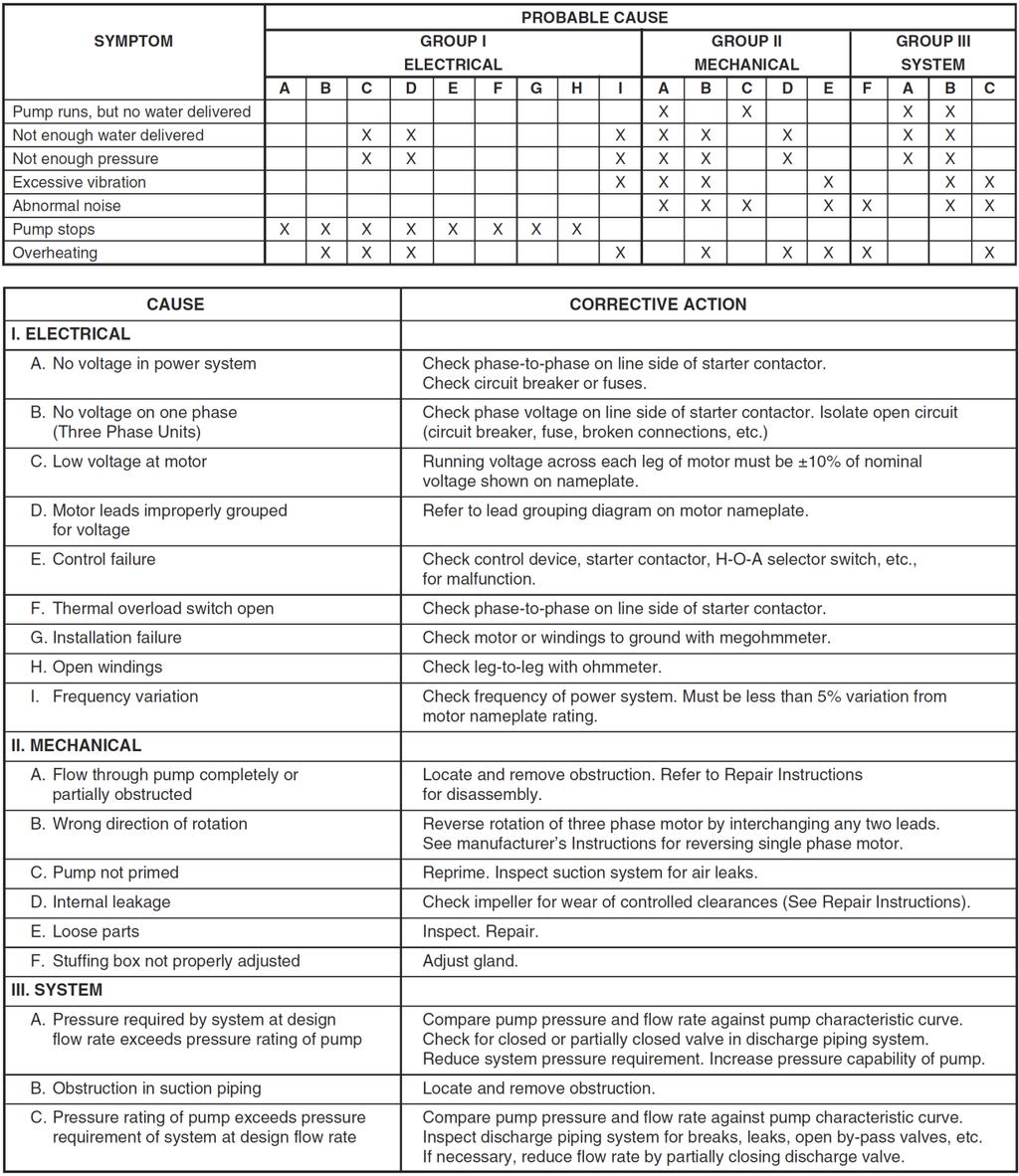
30 Troubleshooting Pump pg. 30
Duplex Booster System Instruction Manual
 Duplex Booster System Instruction Manual ISO 9001 Certified Walrus America Inc Congratulations on your purchase of Walrus IC Series Inverter Control System. Please read all instructions carefully before
Installation & Operating Manual
 Installation & Operating Manual 25IPCC-M 7/08 Edition PC Series C E N T R I F U G A L Congratulations On Your Choice In Purchasing This Webtrol Pump Its Quality is unsurpassed in material and workmanship
ADVANCED PID TROUBLESHOOTING
 ADVANCED PID TROUBLESHOOTING August 29, 2016 A KEY POINT If the drive is telling you something via a Fault, then the problem is probably not the drive. The drive is recognizing a fault and telling you
Matrix APAX. 380V-415V 50Hz TECHNICAL REFERENCE MANUAL
 Matrix APAX 380V-415V 50Hz TECHNICAL REFERENCE MANUAL WARNING High Voltage! Only a qualified electrician can carry out the electrical installation of this filter. Quick Reference ❶ Performance Data Pages
SineWave Guardian TM 380V 600V INSTALLATION GUIDE. Quick Reference. ❶ How to Install Pages 6 17 ❷ Startup/Troubleshooting Pages WARNING
 SineWave Guardian TM 380V 600V INSTALLATION GUIDE FORM: SWG-IG-E REL. October 2018 REV. 003 2018 MTE Corporation High Voltage! Only a qualified electrician can carry out the electrical installation of
Airflow Controller. Installation and Operation Manual Installation, Operation, Service and Replacement Parts Information. IOM AD Revision 1
 Airflow Controller Installation and Operation Manual Installation, Operation, Service and Replacement Parts Information This manual is property of the owner. Leave with the unit when set-up and start-up
TW W-40 FLAG FRAME VARIABLE SPEED BOOSTER SYSTEM
 TW1000-20W-40 FLAG FRAME VARIABLE SPEED BOOSTER SYSTEM TW1000-20W-40 FLAG FRAME The TW1000-20W-40 Flag Frame Booster System is equipped with a centrifugal pump regulated by a variable frequency drive that
High Frequency SineWave Guardian TM
 High Frequency SineWave Guardian TM 380V 480V INSTALLATION GUIDE FORM: SHF-IG-E REL. January 2018 REV. 002 2018 MTE Corporation High Voltage! Only a qualified electrician can carry out the electrical installation
Duo Battery Charge Controller
 Duo Battery Charge Controller RENOGY 10A 20A Pulse Width Modulation Solar Charge Controller Manual 1 2775 E. Philadelphia St., Ontario CA 91761 1-800-330-8678 Version: 1.2 Important Safety Instructions
Quick Reference Guide. For NFX9000 Adjustable Frequency Drives. February 2006 NQ00. MN E February 2006
 Quick Reference Guide For NFX9000 Adjustable Frequency Drives February 2006 5011640900 NQ00 MN04001003E February 2006 Hazardous High Voltage WARNING Motor control equipment and electronic controllers are
TECHNICAL PAPER 1002 FT. WORTH, TEXAS REPORT X ORDER
 I. REFERENCE: 1 30 [1] Snow Engineering Co. Drawing 80504 Sheet 21, Hydraulic Schematic [2] Snow Engineering Co. Drawing 60445, Sheet 21 Control Logic Flow Chart [3] Snow Engineering Co. Drawing 80577,
CHAPTER 7 ERROR MESSAGE AND TROUBLESHOOTING
 CHAPTER ERROR MESSAGE AND TROUBLESHOOTING VFD-V Series The AC drive has a comprehensive fault diagnostic system that includes various alarms and fault messages such as over-voltage, low-voltage and over-current.
Model &
 PumpAgents.com - Click here for Pricing/Ordering Model 31765-0092 & 31765-0094 Dual Sensor Max VSD WATER PRESSURE SYSTEM AUTOMATIC TWO STAGE WATER SYSTEM WITH PUMPGARD STRAINERS IDEAL FOR PLEASURE AND
Installation Instructions
 Installation Instructions Power Exhaust Part Numbers: CRPWREXH07A00 THROUGH CRPWREXH079A00 Conversion Package Numbers: CRPECONV005A00, CRPECONV006A00 CONTENTS Page SAFETY CONSIDERATIONS......................
Installation & Operating Manual
 Installation & Operating Manual Centrifugal Pump SPC75 & SPC150 Self-Priming / Stainless Steel Congratulations On Your Choice In Purchasing This Webtrol Pump Its Quality is unsurpassed in material and
REFERENCE MANUAL FORM: MX-TRM-E REL REV MTE
 Matrix APAX 380V-415V 50Hz TECHNICAL REFERENCE MANUAL FORM: MX-TRM-E REL. September 2014 REV. 002 2014 MTE Corporation WARNING High Voltage! Only a qualified electrician can carry out the electrical installation
UL/NEMA Type 1 & Type 12 FRENIC-HVAC Combination VFD
 UL/NEMA Type 1 & Type 12 FRENIC-HVAC Combination VFD Safety Precautions Read this manual thoroughly before proceeding with installation, connections (wiring), or maintenance and inspection. Ensure you
Centrifugal Constant Pressure Control
 Operating Instructions & Parts Manual Please read and save these instructions. Read carefully before attempting to assemble, install, operate or maintain the product described. Protect yourself and others
ACC Series Power Conditioner OPERATION & INSTALLATION MANUAL
 ACC Series Power Conditioner OPERATION & INSTALLATION MANUAL PHASETEC digital power conditioners are designed to safely operate electrical equipment in the harshest power quality environments. With a wide
ESE Series Cast Iron Sewage Pumps
 Owner s Manual ESE Series Cast Iron Sewage Pumps TABLE OF CONTENTS General Safety.................... 2 Specifications..................... 3 Installation.................... 4 & 5 Troubleshooting...................
Centrifugal Constant Pressure Control
 Operating Instructions & Parts Manual Please read and save these instructions. Read carefully before attempting to assemble, install, operate or maintain the product described. Protect yourself and others
Matrix AP 400V 690V INSTALLATION GUIDE. Quick Reference. ❶ How to Install Pages 6 20 ❷ Startup/Troubleshooting Pages WARNING
 Matrix AP 400V 690V INSTALLATION GUIDE FORM: MAP-IG-E REL. May 2017 REV. 002 2017 MTE Corporation WARNING High Voltage! Only a qualified electrician can carry out the electrical installation of this filter.
FLÄKTGROUP PM-MOTOR WITH INTEGRATED FC 106 FREQUENCY CONVERTER
 FLÄKTGROUP PM-MOTOR WITH INTEGRATED FC 106 FREQUENCY CONVERTER INSTALLATION AND MAINTENANCE INSTRUCTIONS Risk of electric shock: Motor terminals may still be live if the impeller is rotating, even when
ACCESSORY KIT INSTALLATION INSTRUCTIONS
 ACCESSORY KIT INSTALLATION INSTRUCTIONS Low Ambient Accessory For Air Cooled Split-System Air Conditioners HA 00, HB 60 / 80 / 600, HF-25, HL-0 / -0 / -50 Models GENERAL These split-system condensing units
PumpAgents.com - Click here for Pricing/Ordering Fuse Size (A) Open Flow GPM (LPM)
 Open Flow GPM (LPM)") PumpAgents.com - Click here for Pricing/Ordering Models 41700 / 51700 - Series Washdown Pump WASHDOWN PUMP 0 PSI (5.5 BAR) 7.5 GPM (29 LPM) 6.0 GPM (23 LPM) FEATURES High Pressure / High capacity Pumpgard
PumpAgents.com - Click here for Pricing/Ordering Models 41700 / 51700 - Series Washdown Pump WASHDOWN PUMP 0 PSI (5.5 BAR) 7.5 GPM (29 LPM) 6.0 GPM (23 LPM) FEATURES High Pressure / High capacity Pumpgard
USER'S GUIDE. WiseHP11 SINGLE PHASE HIGH PRECISION AVR SERVO-MOTOR AUTOMATIC VOLTAGE STABILIZER
 USER'S GUIDE WiseHP11 SINGLE PHASE HIGH PRECISION AVR SERVO-MOTOR AUTOMATIC VOLTAGE STABILIZER LEN.MAN.STA.145 Rev.5.00/2010 CONTENTS 1. SAFETY INSTRUCTIONS 1 2. INTRODUCTION 2 3. FRONT PANEL AND INSIDE
VERTICAL MULTI-STAGE CENTRIFUGAL PUMPS
 Installation and Operating Instructions VERTICAL MULTI-STAGE CENTRIFUGAL PUMPS Models 1, 3, 5, 10, 15, 20, 32, 45, 64, 90 1. Model numbering and nameplate format 1.1 Model numbering Example: SBI / SBN
IntelliPro VS-3050 Variable Speed Swimming Pool Pump. Quick-Start Guide. Step-by-step instructions for easy set-up and operation
 IntelliPro VS-3050 Variable Speed Swimming Pool Pump Quick-Start Guide Step-by-step instructions for easy set-up and operation Table of Contents PAGE 1 Before You Get Started 2 The Performance Secret 4
Blower Drive Checkout for 3GIBC1 Systems
 Blower Drive Checkout for 3GIBC1 Systems Introduction This document covers troubleshooting of the interface between the Generation 3 version of the ISIBC1 Internal Bubble Cooling control system and the
Operating Manual Includes Pumps: PG-9000 Part #R809606
 Operating Manual Includes Pumps: PG-9000 Part #R809606 Introduction Thank you for selecting the PG Series Pumps from Lifegard Aquatics. Before using this pump please take a moment to review this manual.
Mitsubishi. VFD Manuals
 Mitsubishi VFD Manuals Mitsubishi D700 VFD Installation Mitsubishi FR-D700 VFD User Manual Mitsubishi D700 Parallel Braking Resistors VFD Wiring Diagram - Apollo Mitsubishi VFD to Interpreter Mitsubishi
CURTIS TOLEDO. AF Series Compressors VS models with VFD WARNING
 AUGUST, 2004 REV.A CURTIS TOLEDO OPERATOR S MANUAL SUPPLEMENT AF Series Compressors VS models with VFD WARNING Personal injury and/or equipment damage will result by failing to pay attention to the vital
RVS-AX Instruction Manual
 RVS-AX Analog Soft Starter 8-170A, 220-600V Instruction Manual Ver. 10/11/2009 2 Table of Content RVS-AX Instruction Manual 1. TABLE OF CONTENT 1. Table of Content...2 2. Safety & Warnings...3 2.1 Safety...3
VERTICAL MULTI-STAGES CENTRIFUGAL PUMPS
 Installation and Operating Instructions VERTICAL MULTI-STAGES CENTRIFUGAL PUMPS Models 1, 3, 5, 10, 15, 20, 32, 45, 64, 90, 120, 150 1. Model numbering and nameplate format 1.1 Model numbering Example:
VADA - V60-J PRODUCT OVERVIEW CONSTRUCTION MOTOR USAGE LIMITATIONS WARRANTY
 PRODUCT OVERVIEW The VADA series of self priming jet pumps combine the functional benefits of centrifugal pumps and the practical and qualitative benefits of self-priming pumps. The Venturi system the
ACCESSORY KIT INSTALLATION INSTRUCTIONS
 ACCESSORY KIT INSTALLATION INSTRUCTIONS GENERAL Low Ambient Accessory For Air Cooled Split-System Air Conditioners HA 00, HB 60 / 80 / 600, HF-25, HL-0 / -0 / -50 Models These split-system condensing units
TW1000E-20W-70-DCA In Enclosure w/ Double Check Assembly VARIABLE SPEED BOOSTER SYSTEM
 TW1000E-20W-70-DCA In Enclosure w/ Double Check Assembly VARIABLE SPEED BOOSTER SYSTEM Revised 7/28/16 The TW1000E-20W-70-DCA booster system is equipped with a Stainless Steel centrifugal pump and regulated
Product Guide: Series III Pump Control Board Set (RoHS)
") revised 04/08/10 Description: The Series III Pump Control Board Set provides motor drive and pump control for a wide assortment of pumps from Scientific Systems, Inc. The assembly consists of two circuit
revised 04/08/10 Description: The Series III Pump Control Board Set provides motor drive and pump control for a wide assortment of pumps from Scientific Systems, Inc. The assembly consists of two circuit
DuraMAC LIGHT COMMERCIAL & IRRIGATION WATER PRESSURE BOOSTER SYSTEM INSTALLATION INSTRUCTIONS
 DuraMAC LIGHT COMMERCIAL & IRRIGATION WATER PRESSURE BOOSTER SYSTEM INSTALLATION INSTRUCTIONS The DuraMAC TM Water Pressure Booster System is the first booster pump of its kind to be designed for virtually
Delta Products VFD CP2000 Bypass Control Packages.
 Delta Products VFD CP2000 Bypass Control Packages www.deltaww.com Delta Products VFD CP2000 Bypass Control Packages The Delta Products VFD CP2000 Bypass Control Packages are designed for the Delta Products
Installation and Operating Instructions for Davey HM Series Pressure Systems with Pressure Switch
 Davey Repair or Replacement Guarantee In the unlikely event in Australia or New Zealand that this Davey product develops any malfunction within two years of the date of original purchase due to faulty
TW G-40 FLAG FRAME VARIABLE SPEED BOOSTER PUMP SYSTEM
 TW1000-75G-40 FLAG FRAME VARIABLE SPEED BOOSTER PUMP SYSTEM The TW1000-75G-40 Flag Frame Booster System is equipped with a centrifugal pump regulated by a variable frequency drive that controls the pump
BoosterpaQ Grundfos CR-Booster Systems 60 Hz Installation and operating instructions
 GRUNDFOS INSTRUCTIONS BoosterpaQ Grundfos CR-Booster Systems 60 Hz Installation and operating instructions Factory settings are documented in this manual. Please leave these instructions with the BoosterpaQ
CI-tronic Soft starters for Danfoss commercial compressor applications Type MCI 15C, MCI 25C, MCI 50CM-3 I-O
 Data sheet CI-tronic Soft starters for Danfoss commercial compressor applications Type, MCI 25C, MCI 50CM-3 I-O The MCI compressor soft starters are designed for soft starting of 3 phase compressors. During
DCS7 Water Softener - Product Manual
 pg. 0 Set Up Instructions for DCS7 Water Softener Inspect the packaging of the equipment to confirm that nothing was damaged during shipping. (Figure 1) Remove the resin tank(s) and valve(s) from the packaging.
VFD - Mitsubishi. VFD Manuals. Mitsubishi D700 VFD Installation. Mitsubishi FR-D700 VFD User Manual. Mitsubishi D700 Parallel Braking Resistors
 VFD - Mitsubishi VFD Manuals Mitsubishi D700 VFD Installation Mitsubishi FR-D700 VFD User Manual Mitsubishi D700 Parallel Braking Resistors VFD Wiring Diagram - Apollo Mitsubishi VFD to Interpreter Mitsubishi
M-3025CB-AV Fuel Pump
 SAVE THESE INSTRUCTIONS M-3025CB-AV Fuel Pump Owner s Manual TABLE OF CONTENTS General Information... 2 Safety Instructions... 2 Installation... 3 Operation... 4 Maintenance... 4 Repair... 5 Troubleshooting...
Centrifugal Pumps (Part Nos. PS2SS PS73SS) PS2SS
 PS2SS") Centrifugal Pumps (Part Nos. PS2SS PS73SS) PS2SS Part No. Serial Number Date Purchased Table of Contents Page Safety Messages...2 Pump Curves...2 Pump End Assembly...3 Disassembly...3 Installation...4
Centrifugal Pumps (Part Nos. PS2SS PS73SS) PS2SS Part No. Serial Number Date Purchased Table of Contents Page Safety Messages...2 Pump Curves...2 Pump End Assembly...3 Disassembly...3 Installation...4
MAKING MODERN LIVING POSSIBLE. Quick Setup VLT FCM 300 Series. Phone: Fax: Web: -
 MAKING MODERN LIVING POSSIBLE Quick Setup VLT FCM 300 Series Factory setting Motors type B14 & B34 mounting Reset (pushbutton) Start Jog Speed reference Fig. 1 - Reset to be closed short time for resetting
Pump Station. Models ADW2W31, ADW2W51, ADW2W71, ADW2W73
 Operating Instructions & Parts Manual Please read and save these instructions. Read carefully before attempting to assemble, install, operate or maintain the product described. Protect yourself and others
Commander Pro Variable Speed Controller System Instructions
 Commander Pro Variable Speed Controller System Instructions The Commander Pro Variable Speed Controller is a dependable water system Variable Frequency Drive (VFD) that uses custom programming to enhance
A Series 50HZ. A - Series. Vertical Multistage Centrifugal in-line Pumps AVC/AVI/AVS ISO-9001
 A - Series A Series ISO-9 AVC/AVI/AVS HZ Evak Pump Technology Corp. No., Zhongshan Rd., Qingshui Township, Taichung County, Taiwan. Tel : +-- Fax: +--9 www.evak-pumps.com Vol. PIAV- A-Series Index Multistage
User Manual Solar Charge Controller 3KW
 User Manual Solar Charge Controller 3KW Version: 1.3 CONTENTS 1 ABOUT THIS MANUAL... 1 1.1 Purpose... 1 1.2 Scope... 1 1.3 SAFETY INSTRUCTIONS... 1 2 INTRODUCTION... 2 2.1 Features... 2 2.2 Product Overview...
Installation Instructions Light Commercial & Irrigation Water Pressure Booster System
 Installation Instructions DuraMAC TM Light Commercial & Irrigation Water Pressure Booster System The DuraMAC TM Water Pressure Booster System is the first booster pump of its kind to be designed for virtually
MPPT SOLAR CONTROLLER FOR MODELS: 20A baterai 12V 24V
 Main Features MPPT SOLAR CONTROLLER FOR MODELS: 20A baterai 12V 24V 20A MPPT solar charge controller MPPT technology Built-in DSP controller with high performance Automatic battery voltage detection for
SUBMERSIBLE PUMP HSE RANGE
 SUBMERSIBLE PUMP HSE RANGE OPERATION & MAINTENANCE INSTRUCTIONS 0707 SPECIFICATIONS HSE300* HSE360* Model No. HSE130* HSE200A HSE300A HSE360A HSEC400* HSE301A HSE361A Outlet Dia. (mm/inches) 32/1-1/4 38/1-1/2
TW W-40 FLAG FRAME VARIABLE SPEED BOOSTER PUMP SYSTEM
 TW1000-20W-40 FLAG FRAME VARIABLE SPEED BOOSTER PUMP SYSTEM TW1000-20W-40 FLAG FRAME The TW1000-20W-40 Flag Frame Booster System is equipped with a centrifugal pump regulated by a variable frequency drive
Matala. VersiFlow Series. Instruction and Maintenance Manual
 VersiFlow Series High Flow Multi-Purpose "Versatile " Pump V-3200 1/5HP 150W / Discharge 2 V-3900 1/3HP 250W / Discharge 2 V-4700 1/2HP 400W / Discharge 2 V-5600 1HP 750W / Discharge 2 Instruction and
1333 (SERIES B & C) TROUBLESHOOTING GUIDE
 TROUBLESHOOTING GUIDE") 1333 (SERIES B & C) TROUBLESHOOTING GUIDE Preventive Maintenance: Problems with Your Drive? Bulletin 1333 is convection or fan cooled by air flowing through the heat sink slots. The slots must never be
1333 (SERIES B & C) TROUBLESHOOTING GUIDE Preventive Maintenance: Problems with Your Drive? Bulletin 1333 is convection or fan cooled by air flowing through the heat sink slots. The slots must never be
Installation & Operating Manual
 Installation & Operating Manual VN Series Non-Clog Pumps Congratulations On Your Choice In Purchasing This Webtrol Pump 10/15 Edition Its Quality is unsurpassed in material and workmanship and has been
Motor Controllers AC Semiconductor Motor Controller Type RSHP Flexy
 Controllers AC Semiconductor Controller Type Soft starting and stopping of -phase induction squirrel cage motors Low inrush and reduced vibration during starting User-selected ramping profiles Integral
DC Variable Speed Drive Panel
 DC Variable Speed Drive Panel Installation, Operation & Maintenance Instruction Manual Bulletin #: CC-IOM-0103-D Manufacturers of Quality Pumps, Controls and Systems ENGINEERED PUMP OPERATIONS 2883 Brighton
PRESSURE BOOSTER 150
 PRESSURE BOOSTER 150 Owners Manual! WARNING This equipment must be installed and serviced by a qualified technician. Improper installation can create electrical hazards which could result in property damage,
CI-tronic Soft Start Motor Controller Type MCI 25B with Brake
 Data sheet CI-tronic Soft Start Motor Controller Type MCI 25B with Brake MCI 25B motor controller with brake is designed for soft starting and braking of 3 phase AC motors. The digital controlled soft
GeyserMax-Flow Series
 GeyserMax-Flow Series 115V/60Hz Waterfall Pump GM-3900 1/5HP 150W / Discharge 1-1/2 GM-4700 1/3HP 250W / Discharge 2 GM-5400 1/2HP 400W / Discharge 2 GM-6200 3/4HP 750W / Discharge 2 230V/50Hz GM-3800
OPERATION MANUAL, POWER MODULE-CHARGER SYSTEM. Man Occup. Machine Occup. Cycle Time Setup Time Batch Qty. Equipment Manufacturer Qty
 Rev Description Date ECO# Document Number: OPERATION MANUAL 3/24/08 00263 Form Instructions Title Operation Description Standards OPERATION MANUAL, POWER MODULE-CHARGER SYSTEM Power Module-Charger System
MAKING MODERN LIVING POSSIBLE. Design Guide VLT MCD 100 Soft Starter the single speed drive
 MAKING MODERN LIVING POSSIBLE Design Guide VLT MCD 100 Soft Starter the single speed drive Contents Contents 1.1.1 Introduction 2 1.2 Technical Data 3 1.3.1 Functional Diagram 4 1.3.4 Wiring 5 1.3.5 Adjustments
dv Sentry TM 208V 600V INSTALLATION GUIDE Quick Reference ❶ How to Install Pages 6 14 ❷ Startup/Troubleshooting Pages WARNING
 dv Sentry TM 208V 600V INSTALLATION GUIDE FORM: DVS-IG-E REL. January 2018 REV. 003 2018 MTE Corporation High Voltage! Only a qualified electrician can carry out the electrical installation of this filter.
END SUCTION CENTRIFUGAL PUMPS
 OWNERS GUIDE TO INSTALLATION AND OPERATION FW000 009 Supersedes 07 END SUCTION CENTRIFUGAL PUMPS READ THESE INSTRUCTIONS CAREFULLY Read these installation instructions in detail before installing your
ACCESSORY KIT INSTALLATION INSTRUCTIONS Low Ambient Accessory For Air Cooled Split System Air Conditioners HB 180/240, HF -15,-20 Models Only
 ACCESSORY KIT INSTALLATION INSTRUCTIONS Low Ambient Accessory For Air Cooled Split System Air Conditioners HB 180/240, HF -15,-20 Models Only GENERAL These split-system condensing units are designed to
A Series 50HZ. A - Series. Vertical Multistage Centrifugal in-line Pumps AVC/AVI/AVS ISO-9001
 A - Series A Series ISO-9 AVC/AVI/AVS HZ Evak Pump Technology Corp. No., Zhongshan Rd., Qingshui Township, Taichung County, Taiwan. Tel : +-- Fax: +--9 www.evak-pumps.com Vol. PIAV- A-Series Index Pump
U.S LIST PRICES
 PENTEK STA-RITE 4 SUBMERSIBLE MOTORS AND CONTROLS U.S. 2015 PRICES S10847P EFFECTIVE: DECEMBER 1, 2014 SUPERSEDES ALL PREVIOUS PRICE S Table of Contents Description Page XE Series MOTORS 2 XE Series controls
Design Guide. VLT Soft Start Controller MCD 100
 Design Guide VLT Soft Start Controller MCD 100 Introduction The MCD 100 soft starters are designed for soft starting and stopping of 3 phase a.c. motors, thus reducing the inrush current and eliminating
PowerFLO 7800 Series 12 Volt DC Motor-Driven Diaphragm Pumps
 Installation Operation Repair Parts PowerFLO 7800 Series 12 Volt DC Motor-Driven Diaphragm Pumps Specifications Motor Type: 12 VDC, permanent magnet, totally enclosed, non-ventilated Leads: 14 AWG, 12
INSTALLATION AND OPERATING INSTRUCTIONS. EXP Hurlcon Pumps CTX Series & BX Series. Bolero ND Cleaner
 INSTALLATION AND OPERATING INSTRUCTIONS I INSTALLATION AND OPERATING INSTRUCTIONS EXP Hurlcon Pumps CTX Series & BX Series Bolero ND Cleaner INSTALLATION AND OPERATING INSTRUCTIONS 1/08/2014 INST 278 EXPORT
Data sheet. CI-tronic Soft start motor controller Type MCI 3, MCI 15, MCI 25, MCI 30 I-O, MCI 50 I-O 520B1443
 CI-tronic Soft start motor controller Type MCI 3, MCI 15, MCI 25, MCI 30 I-O, MCI 50 I-O December 2002 DKACT.PD.C50.G2.02 520B1443 2 DKACT.PD.C50.G2.02 Danfoss A/S 12-2002 Introduction The MCI soft starters
OPERATING MANUAL. centrifugal fan SAFETY PRACTICES
 2237 MARSHALLTOWN BLVD. MARSHALLTOWN, IOWA 50158 PHONE: (641) 753-5601 TOLL FREE: 1-800-383-5601 FAX: (641) 752-9748 WWW.SPREAD-ALLMFG.NET OPERATING MANUAL centrifugal fan SAFETY PRACTICES 1. Have a qualified
ADJUSTABLE FREQUENCY CONTROLS SENSORLESS VECTOR CONTROL. Dual Rating. Technologies Inc. mgitech.com NRTL/C CERTIFIED
 ADJUSTABLE FREQUENCY CONTROLS SENSORLESS VECTOR CONTROL Dual Rating NRTL/C CERTIFIED Technologies Inc. mgitech.com Sensor/Sensorless Vector Control Dual current rated for constant and variable torque Auto
CTi Automation - Phone: Fax: Web:
 CTi Automation - Phone: 800.894.0412 - Fax: 208.368.0415 - Web: www.ctiautomation.net - Email: info@ctiautomation.net The control & protection you expect in an innovative soft starter design... Flexibility
OPERATION & MAINTENANCE INSTRUCTIONS
 400W SUBMERSIBLE PUMP WITH FOLDING BASE AND FLOAT SWITCH MODEL NO: PSV6A PART NO: 7230695 OPERATION & MAINTENANCE INSTRUCTIONS LS0315 INTRODUCTION Thank you for purchasing this CLARKE 400W Submersible
L-SERIES PUMPS. Operating Manual. Includes Pumps: L-305 L PONDS
 L-SERIES PUMPS Operating Manual Includes Pumps: L-305 L-310 1-877-80-PONDS www.atlanticwatergardens.com Introduction Thank you for selecting the TidalWave L-305/L-310 series pumps. Before using this pump
PerfectSpeed NEMA 48 Pump Motor. With User Interface
 PerfectSpeed NEMA 48 Pump Motor With User Interface Table of Contents Section 1 - PerfectSpeed Motor... 1 Important Safety Information...1 Overview...3 PerfectSpeed User Interface Box...4 Minimum and Maximum
F-4600 INLINE ULTRASONIC FLOW METER Installation and Operation Guide
 F-4600 INLINE ULTRASONIC FLOW METER Installation and Operation Guide 11451 Belcher Road South, Largo, FL 33773 USA Tel +1 (727) 447-6140 Fax +1 (727) 442-5699 1054-7 / 34405 www.onicon.com sales@onicon.com
GARDEN HOSE UTILITY PUMP
 GARDEN HOSE UTILITY PUMP MODEL #HPP360, HPP12V, 473707 MODEL #HPP360, 473707 MODEL #HPP12V ATTACH YOUR RECEIPT HERE Purchase Date SAFETY INFORMATION Please read and understand this entire manual before
Installation Operation & Maintenance Manual. Oil-Free (Dry) Rotary Vane Vacuum Pump Systems
 Rotary Vane Vacuum Pump Systems") Installation Operation & Maintenance Manual Oil-Free (Dry) Rotary Vane Vacuum Pump Systems Part No. 9983-0000-S07 / November 2018 OIL-FREE (DRY) ROTARY VANE VACUUM PUMP SYSTEMS TABLE OF CONTENTS CUSTOMER
Installation Operation & Maintenance Manual Oil-Free (Dry) Rotary Vane Vacuum Pump Systems Part No. 9983-0000-S07 / November 2018 OIL-FREE (DRY) ROTARY VANE VACUUM PUMP SYSTEMS TABLE OF CONTENTS CUSTOMER
C1 Controller & Driver. User s Guide
 Controller & Driver User s Guide Page 1 of 12 Table of Contents Warnings & Notices 2 Quick Start Procedure 3 Factory Default Settings 4 System Setup Position 5 Force 5 Pressure 5 Flow 6 Wiring 7 Potentiometers/Tuning
Induction Power Supplies
 Induction Power Supplies 7.5kW; 135 400kHz 480V version (Integral Heat Station) User s Guide Model 7.5-135/400-3-480 SMD Control Brds Rev. D 5/08 Table of Contents 1. Specifications and features...3 2.
VARNA Products 15 GPM (57 LPM) Prelube Kit for MTU 4000 Series Marine Engines
 Prelube Kit for MTU 4000 Series Marine Engines") VARNA Products 15 GPM (57 LPM) Prelube Kit for MTU 4000 Series Marine Engines Installation and Users Manual For the following Prelube Kits: VARNA Products P/N 6423 Kit for 208 VAC 3 Phase VARNA Products
VARNA Products 15 GPM (57 LPM) Prelube Kit for MTU 4000 Series Marine Engines Installation and Users Manual For the following Prelube Kits: VARNA Products P/N 6423 Kit for 208 VAC 3 Phase VARNA Products
ST Charger. Industrial Battery Charger
 ST Charger Industrial Battery Charger Installation and Operation Manual ST_13 Table of Contents Pg# 1.0 INSTALLATION 1 1.1 Receiving 1 1.2 Location 1 1.3 Line Voltage 1 1.4 A.C. Service Requirements 2
CHILLER MANUAL. SAM JUNG ENC CO.,LTD.
 CHILLER MANUAL SAM JUNG ENC CO.,LTD. http:/www.speedchiller.com E-Mail: sskim8913@naver.com 756-1, Kwarim-dong, shiheung-city, Kyeong-ki 429-120, Korea TEL: 02)2686-3315~6 / 02)2686-3658 FAX: TEL02)2686-3317
M T E C o r p o r a t i o n MATRIX FILTER. SERIES B Volts, 50HZ USER MANUAL PART NO. INSTR REL MTE Corporation
 M T E C o r p o r a t i o n MATRIX FILTER SERIES B 380-415 Volts, 50HZ USER MANUAL PART NO. INSTR - 015 REL. 040709 2003 MTE Corporation IMPORTANT USER INFORMATION NOTICE The MTE Corporation Matrix Filter
User Manual. Solar Charge Controller 3KW
 User Manual Solar Charge Controller 3KW 1 CONTENTS 1 ABOUT THIS MANUAL... 3 1.1 Purpose... 3 1.2 Scope... 3 1.3 SAFETY INSTRUCTIONS... 3 2 INTRODUCTION... 4 2.1 Features... 4 2.2 Product Overview... 5
Gas Engine overheat diagnosis
 Gas Engine overheat diagnosis Introduction... 2 Six Step Troubleshooting Method... 3 Diagnostic Tips... 4 Clear Hose Testing Equipment... 5 Clear Hose Setup (Pump)... 6 Clear Hose Setup (Engine)... 7 Gauge
User Manual. T6 Tachometer. Online: Telephone: P.O. Box St. Petersburg, Florida 33736
 User Manual T6 Tachometer Online: www.phareselectronics.com Telephone: 727-623-0894 P.O. Box 67251 St. Petersburg, Florida 33736 Table of Contents Overview... 1 Description... 1 Wiring... 1 T6 Tachometer
DIGITAL RCD(ELCB) TESTER
 TESTER") INSTRUCTION MANUAL DIGITAL RCD(ELCB) TESTER KEW 5410 R KYORITSU ELECTRICAL INSTRUMENTS WORKS, LTD. Contents 1. Safety Warnings.... 1 2. Procedure of removing Cover. 3 2-1 Method of removing the Cover.
INSTRUCTION MANUAL DIGITAL RCD(ELCB) TESTER KEW 5410 R KYORITSU ELECTRICAL INSTRUMENTS WORKS, LTD. Contents 1. Safety Warnings.... 1 2. Procedure of removing Cover. 3 2-1 Method of removing the Cover.
VECTOR INVERTER -INSTRUCTION MANUAL- ADDITIONAL OPEN COLLECTOR OUTPUT / PLG PULSE DIVISION OUTPUT FR-V5AY
 VECTOR INVERTER -INSTRUCTION MANUAL- ADDITIONAL OPEN COLLECTOR OUTPUT / PLG PULSE DIVISION OUTPUT FR-V5AY Thank you for choosing the Mitsubishi vector inverter option unit. This instruction manual gives
Application example of a motor controlled by MCD100 and protected by a circuit breaker
 VLT T Soft Start Controller MCD 100 MCD 100 is a cost effective and extremely compact soft starter for AC motors up to 11 kw. Due to a unique semiconductor design MCD 100 is a true fit and forget product.
Submersible Motors, Controls and Accessories
 Submersible Motors, Controls and Accessories Canada 2012 List Prices P8062WS-CN 02/01/12 Effective: February 1, 2012 Supersedes All Previous Price Lists Table of Contents Description Page 4" XE Series
BLDPN30001 Series. 30A Brushless DC Controller. User s Guide E. Landon Drive Anaheim, CA
 BLDPN30001 Series 30A Brushless DC Controller User s Guide A N A H E I M A U T O M A T I O N 4985 E. Landon Drive Anaheim, CA 92807 e-mail: info@anaheimautomation.com (714) 992-6990 fax: (714) 992-0471
WARNING This manual should only be used by a qualified Service Technician. FinishPro 390/395 Airless/Air-Assisted Sprayer Repair Electrical Manual
 FinishPro 390/395 Airless/AirAssisted Sprayer Repair Electrical Manual First choice when quality counts. Rev. B 10/11 /07 FinishPro 395 3.00 ti9026a Red Yel Yel Air Hose Connection FinishPro 390 Exhaust