Duo Battery Charge Controller
|
|
|
- Cecil Dawson
- 6 years ago
- Views:
Transcription


1 Duo Battery Charge Controller RENOGY 10A 20A Pulse Width Modulation Solar Charge Controller Manual E. Philadelphia St., Ontario CA Version: 1.2
2 Important Safety Instructions Please save these instructions. This manual contains important safety, installation, and operating instructions for the charge controller. The following symbols are used throughout the manual to indicate potentially dangerous conditions or important safety information. WARNING: Indicates a potentially dangerous condition. Use extreme caution when performing this task. CAUTION: Indicates a critical procedure for safe and proper operation of the controller NOTE: Indicates a procedure or function that is important to the safe and proper operation of the controller. General Safety Information Read all of the instructions and cautions in the manual before beginning the installation. There are no serviceable parts for this controller. Do NOT disassemble or attempt to repair the controller. Disconnect the solar module and fuse/breakers near to battery before installing or adjusting the PWM1020CC-DB. Install external fuses/breakers as required. Do NOT allow water to enter the controller. Confirm that the power connections are tightened to avoid excessive heating from a loose connection. Charge Controller Safety NEVER connect the solar panel array to the controller without a battery. Battery must be connected first. Ensure input voltage does not exceed 30 VDC (for 12V system) or 55VDC (for 24V system) to prevent permanent damage. Use the Open Circuit (V oc) to make sure the voltage does not exceed this value when connecting panels together. Do not exceed 10A (PWM10DB) or 20A (PWM20DB). The Short Circuit (I sc) of the solar array should be less than 10A (PWM10DB) or 20A (PWM20DB). 2
3 Battery Safety Use only sealed lead-acid, flooded, or gel batteries which must be deep cycle. Explosive battery gases may be present while charging. Be certain there is enough ventilation to release the gases. Be careful when working with large lead acid batteries. Wear eye protection and have fresh water available in case there is contact with the battery acid. Carefully read battery manuals before operation. Do NOT let the positive (+) and negative (-) terminals of the battery touch each other. Recycle battery when it is replaced. Over-charging and excessive gas precipitation may damage the battery plates and activate material shedding on them. Too high of an equalizing charge or too long of one may cause damage. Please carefully review the specific requirements of the battery used in the system. Equalization is carried out only for non-sealed / vented/ flooded / wet cell lead acid batteries. Do NOT equalize sealed / VRLA type AGM / Gel cell batteries UNLESS permitted by battery manufacturer. WARNING: Connect battery terminals to the charge controller BEFORE connecting the solar panel(s) to the charge controller. NEVER connect solar panels to charge controller until the battery is connected. WARNING: Do NOT connect any inverters or battery charger into the load terminal of the charge controller. WARNING: Once equalization is active in the battery charging, it will not exit this stage unless there is adequate charging current from the solar panel. There should be NO load on the batteries when in equalization charging stage. 3
4 Table of Contents General Information...5 Optional Components...6 Identification of Parts...7 Installation...8 Operation Troubleshooting Maintenance Fusing Technical Specifications Dimensions
5 General Information The Renogy PWM1020CC-DB features dual battery charging capability making it great for RVs, caravans, and boats. With its advanced PWM charging technology, your batteries will be protected from discharging and over-charging. This controller is specifically designed for mobile off-grid applications supporting 12V deep cycle battery varieties such as sealed lead acid, gel, and flooded. The built-in RJ45 connector gives you the freedom of monitor the voltage, current and temperature of your system via MT-1 remote meter (sold separately). Key Features 12V / 24V auto recognition Micro controller digital accuracy High efficient PWM charging, increase the battery lifetime and improve the solar system performance. Dual battery charging Sealed, Gel, and Flooded battery option. Remote temperature sensor (sold separated) Corrects the charging and discharging parameters automatically based on temperature compensation, improving battery lifetime. Short circuit protection Battery reverse polarity protection Overcharging or discharging protection Overload protection PWM Technology The PWM 10A/20ACC-Dual Battery utilizes Pulse Width Modulation (PWM) technology for battery charging. Battery charging is a current based process so controlling the current will control the battery voltage. For the most accurate return of capacity, and for the prevention of excessive gassing pressure, the battery is required to be controlled by specified voltage regulation set points for Absorption, Float, and Equalization charging stages. The charge controller uses automatic duty cycle conversion, creating pulses of current to charge the battery. The duty cycle is proportional to the difference between the sensed battery voltage and the specified voltage regulation set point. Once the battery reached the specified voltage range, pulse current charging mode allows the battery to react and allows for an acceptable rate of charge for the battery level. 5
: Measures the temperature at the battery and uses this data for very accurate temperature compensation.")
 Figure 1 LCD Display Tracer Meter (MT-1): Allows for real time monitoring of the charge controller.")
6 Optional Components *The PWM10A/20A-Dual Battery charge controller is shipped by itself, without any additional components. Optional components that require a separate purchase: Remote Temperature Sensor (TS-R): Measures the temperature at the battery and uses this data for very accurate temperature compensation. The sensor is supplied with a 6.6ft cable length that connects to the charge controller. (Figure 1) Figure 1 LCD Display Tracer Meter (MT-1): Allows for real time monitoring of the charge controller. Perfect for circumstances where the user cannot easily access the controller or modify its parameters. It is supplied with a mounting frame and a cable that connects to the RJ45 port on the Dual Battery Charge Controller. (Figure 2) Figure 2 6


 a connection point for RTS")
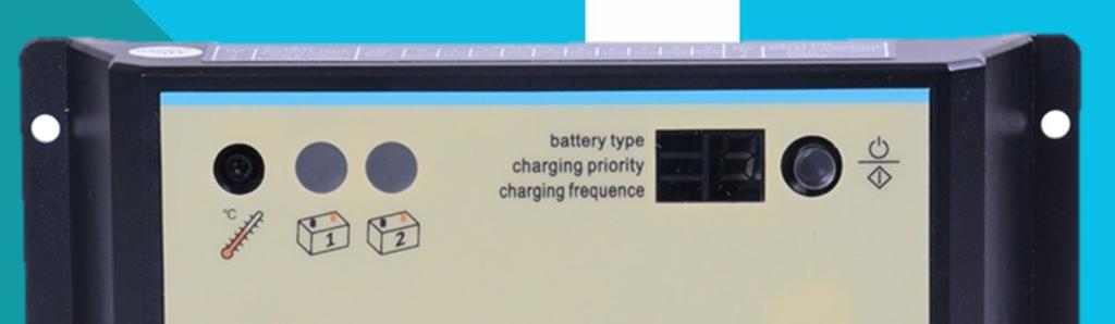
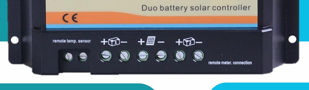
7 Identification of Parts Figure 3 Key Parts 1. Local Temp. Sensor Measures ambient temperature. Battery regulation is adjusted accordingly. 2. Batt #1 status LED Provides charging & battery status and errors 3. Batt #2 status LED Provides charging & battery status and errors 4. Setting Indicator LEDs and Digital Display 5. SET Button 6. Remote Temp. Sensor (sold separately) a connection point for RTS (optional) to remotely monitor battery temperature. 7. Remote Meter Connection (RJ45) a communication port for the remote meter MT-1 (sold separately). 7
8 Installation General Installation Notes Read through the entire installation section first before beginning installation. Be very careful when working with batteries. Wear eye protection. Have fresh water available to wash and clean any contact with battery acid. Uses insulated tools and avoid placing metal objects near the batteries. Explosive battery gasses may be present during charging. Be certain there is sufficient ventilation to release the gasses. Avoid direct sunlight and do not install in locations where water can enter the controller. Loose power connections and/or corroded wires may result in resistive connections that melt wire insulation, burn surrounding materials, or even cause fire. Ensure tight connections and use cable clamps to secure cables and prevent them from swaying in mobile applications. Use with Gel, Sealed or Flooded batteries only. Battery connection may be wired to one battery or a bank of batteries. The following instructions refer to a single battery, but it is implied that the battery connection can be made to either one battery or a group of batteries. Mounting NOTE: When mounting the PWM1020CC-DB, ensure free airflow through the controller heat sink fins. There should be at least 100mm of clearance above and below the controller to allow for cooling. If mounted in an enclosure, ventilation is highly recommended. WARNING: Risk of explosion! Never install the PWM1020CC-DB in a sealed enclose with flooded batteries! Do not install in a confined area where battery gas can accumulate. Step 1: Choose mounting location Locate a vertical or horizontal surface protected from direct sunlight, high temperature, and water. Step 2: Check for Clearance Place the PWM1020CC-D in the location where it will be mounted. Verify that there is sufficient room to run wires and that there is sufficient room above and below the controller for airflow. Step 3: Mark Holes Use a pencil or pen to mark the four (4) mounting hole locations on the mounting surface. Step 4: Drill Holes Remove the controller and drill four sizeable holes in the marked locations. Step 5: Secure Controller Place the controller on the surface and align the mounting holes with the drilled holes in step 4. Secure the controller in place using mounting screws. 8
 to the charge controller. NEVER connect solar panel to charge controller before the battery.")


9 Wiring Recommended tools to have before installation: Flathead Screwdriver Multi-Meter WARNING: Connect battery terminal wires to the charge controller FIRST then connect the solar panel(s) to the charge controller. NEVER connect solar panel to charge controller before the battery. CAUTION: Do not over-torque or over tighten the screw terminals. This could potentially break the piece that holds the wire to the charge controller. CAUTION: Refer to the technical specifications for max wire sizes on the controller and for the maximum amperage going through wires. CAUTION: For mobile applications, be sure to secure all wiring. Use cable clamps to prevent cables from swaying when the vehicle is in motion. Unsecured cables create loose and resistive connections, which may lead to excessive heating and/or fire. You are now ready to begin connecting your battery to your charge controller. Figure 4 Connection order 9
10 Battery Connect Battery 1: Refer to Figure 4, Connect the negative terminal of Battery 1 to the negative terminal of the charge controller under the Battery 1 logo. Then connect the positive terminal of Battery 1 to the positive terminal of the charge controller under the Battery 1 logo. Connect Battery 2: Repeat the process described in last step for Battery 2. Figure 4 shows the connections. If you are not planning on installing a second battery you can skip this step. 10

11 Solar Panels Connect the solar panel(s): Connect the negative PV lead of the solar panel to the negative terminal of the charge controller under the solar array logo. Then connect the positive lead of solar to the positive terminal of the charge controller under the solar array logo. Make sure the solar module(s) voltage and current do not exceed the ratings of the charge controller. 11
12 Temperature Sensor (if applicable) 1 Connect the Remote Temperature Sensor (Optional): If you purchased the remote temperature for your batteries, you can connect it in the remote temperature terminals depicted in Figure 4. If you are not planning on using this sensor, you can skip this step. Note: When the RTS is not present, the controller will calculate the data from the local temperature sensor. The controller will obtain data from RTS automatically when present. MT-1 Tracer (If applicable) 1 2 Connect Remote Meter MT-1 (Optional): The remote meter MT-1 is sold separately and can be connected in the RJ45 communication port. Again, if you are not planning on using this meter, you can skip this step. 12
13 Operation Battery Type To select the battery type press the SET button on the controller a few times until the Battery Type LED lights up. Press the setting button again and hold it for 5 seconds until the digits start flashing. Press the setting button again to choose the battery type as described in Table 1. Leave it in this position, and it will stop flashing after a few seconds. The controller has recorded the battery setting. Battery Type Digital Display Sealed lead acid battery 1 Gel battery 2 Flooded battery 3 Table 1 Battery type setting Charging Priority To adjust the charging priority of the batteries press the setting button on the controller a few times until the Charging priority LED lights up. Press the setting button again and hold it for 5 seconds until the digits start flashing. Press the setting button again to choose the percentage level listed on Table 2. Leave it in this position, and it will stop flashing after a few seconds. The controller has recorded the Charging priority setting. Number Battery #1 Battery #2 0 0% 100% 1 10% 90% 2 20% 80% 3 30% 70% 4 40% 60% 5 50% 50% 6 60% 40% 7 70% 30% 8 80% 20% 9 90% (pre-set) 10% Table 2 Charging priority settings Note: In the normal charging conditions, the controller will distribute the charge for the selected setting. When Battery 1 is fully charged, charge will be diverted to Battery 2, and return to the no. 4 charging priority setting automatically when Battery 1 is low on voltage. When the controller detects that Battery 1 is the only battery connected, all the charge will go to the Battery 1 automatically. Charging frequency To change the charging frequency press the setting button on the controller a few times until the Charging frequency LED lights up. Press the setting button again and hold it for 5 seconds until the digits start flashing. Press the setting button again to choose a charging frequency listed on Table 3. Leave it in this position, and it will stop flashing after a few seconds. The controller has recorded the Charging priority setting. 13
14 Number PWM Charging Frequency 0 25 Hz (pre-set) 1 50 HZ HZ Table 3 Charging frequency settings Battery #1 Status LED Indicator Battery #2 Status LED Indicator Figure 5 Charge controller LED indicators Battery Indicators The LED indicator shown in Figure 5-2 will turn on whenever sunlight is available for battery charging. Under normal charging conditions, the charging LED will lit Green at all times. Color Indication Operating State Green Solid Charging Green Slowly Flashing Full Green Frequent Flashing Not Charging* Green Quickly Flashing Short-circuit* Green Off Battery not Connected / Overvoltage* Table 4 Battery LED indicators *Please refer to the following section for trouble shooting *Please note older version indicators light will be RED 14
15 Troubleshooting Check all connections to ensure they are secure and clean Check polarity of the battery connection and make sure the battery generates at least 6V Ensure the solar panels are exposed to sufficient light ideally position them to face the sun directly If charge controller states that there is short-circuit, please ensure that the panels are connected correctly, and that the wires at the terminals are not touching each other. If one of the status LED is off and a battery is connected, check that the battery terminals have good connection and that the polarity is correct. Check that the voltage doesn t exceed the rated input voltage shown in Table 7-1 on Section 7. If the charge controller is not charging, ensure that the panel s polarity, and check for loose connections. Maintenance For best controller performance, it is recommended that these tasks be performed from time to time. 1. Check that controller is mounted in a clean, dry, and ventilated area. 2. Check wiring going into the charge controller and make sure there is no wire damage or wear. 3. Tighten all terminals and inspect any loose, broken, or burnt up connections 4. Make sure readings in the LEDs are consistent. Fusing Fusing is a recommended in PV systems to provide a safety measure for connections going from panel to controller and controller to battery. Remember to always use the recommended wire gauge size based on the PV system and the controller. NEC Maximum Current for different Copper Wire Sizes AWG Max. 10A 15A 20A 30A 55A 75A 95A 130A 170A Current Table 5 15
16 Fuse from Controller to Battery Controller to Battery Fuse = Current Rating of Charge Controller Ex. 20A Dual Battery CC = 20A fuse from Controller to Battery Fuse from Solar Panel(s) to Controller Ex. 200W; 2 X 100 W panels Series: Total Amperage = I sc1 = I sc2 = 5.75A * 1.56 Fuse = minimum of 5.75A * 1.56 = 8.97A = 9A fuse Parallel Total Amperage = I sc1 + I sc2 = (5.75A A) * 1.56 Fuse = minimum of 11.5 * 1.56 = = 18A fuse Technical Specifications Charge Controller Description Parameter Nominal System Voltage 12VDC/24VDC Auto recognition Rated Charge Current 10A Rated Discharge Current 10A Maximum Battery Voltage 30V Max. Solar Input Voltage 30V (12V), 55V (24V) Max. PV Input Power (10A Model) 120W (12V), 240W (24V) Max. PV Input Power (20A Model) 240W (12V), 480W (24V) Operating Temperature 31 F to +131 F Self-consumption 4mA (idle), 10mA (charging) Terminals 4mm 2 Table 6 Battery Parameters (Temp: 25 C) Control Parameter Battery Charging setting Gel Seared Flooded Equalization Voltage 14.8V 14.4V 14.6V Boost Voltage 14.6V 14.2V 14.4V Float Voltage 13.7V 13.7V 13.7V Boost Duration 30 min 30 min 30 min Table 7 16
17 Dimensions Note: All dimensions are in inches Renogy reserves the right to change the contents of this manual without notice. 17 Revision: 5/9/2017
The Traveler Series: Adventurer
 The Traveler Series: Adventurer RENOGY 30A Flush Mount Charge Controller Manual 2775 E. Philadelphia St., Ontario, CA 91761 1-800-330-8678 Version: 2.2 Important Safety Instructions Please save these instructions.
The Traveler Series TM : Adventurer
 The Traveler Series TM : Adventurer 30A PWM Flush Mount Charge Controller w/ LCD Display 2775 E. Philadelphia St., Ontario, CA 91761 1-800-330-8678 Version: 3.4 Important Safety Instructions Please save
The Traveler Series: Wanderer
 The Traveler Series: Wanderer RENOGY 30A PWM Charge Controller Manual 2775 E. Philadelphia St., Ontario, CA 91761 1-800-330-8678 1 Version: 2.3 Important Safety Instructions Please save these instructions.
The Traveler Series: Wanderer
 The Traveler Series: Wanderer RENOGY 30A Charge Controller Manual 2775 E. Philadelphia St., Ontario, CA 91761 1-800-330-8678 Version: 2.0 Important Safety Instructions Please save these instructions. This
Eclipse Solar Suitcase
 Eclipse Solar Suitcase Renogy 100W 200W 2775 E. Philadelphia St., Ontario, CA 91761 1-800-330-8678 Version 1.0 Important Safety Instructions Please save these instructions. This manual contains important
LS0512 Solar Charge Controller
 LandStar LS0512 Solar Charge Controller Nominal system voltage Maximum PV input voltage Nominal charge / discharge current 12VDC 35V 5A Contents 1 Important Safety Information... 1 2 General Information...
LS0512R Solar Light Controller
 LandStar LS0512R Solar Light Controller Nominal system voltage Maximum PV input voltage Nominal charge / discharge current 12VDC 35V 5A Contents 1 Important Safety Information... 1 2 General Information...
SMT. Installation and Operation Manual. Model:SMT WITH MPPT TECHNOLOGY
 SMT WITH MPPT TECHNOLOGY Installation and Operation Manual Model:SMT SMT Dimensions Specification Summary System Voltage 12 V/24V Rated Battery Current 12V, 5A 8A 10A 15A 20A 25A 24V, 5A 8A 10A 15A Rated
Rover Series. Rover 20A 40A Maximum Power Point Tracking Solar Charge Controller
 Rover Series Rover 20A 40A Maximum Power Point Tracking Solar Charge Controller 0 2775 E. Philadelphia St., Ontario, CA 91761 1-800-330-8678 Version 1.5 Important Safety Instructions Please save these
10A / 15A / 20A Solar Charge Controller. PU1024 / PU1524 / PU2024 series INSTRUCTION MANUAL
 10A / 15A / 20A Solar Charge Controller PU1024 / PU1524 / PU2024 series INSTRUCTION MANUAL Dear Customer, Thank you very much for choosing our product. This manual contains important information about
NSTHAI. Solar Light Controller
 NSTHAI Design patent NO.: 201130028317.3 Utility model patent NO.:201120064092.1 NSC2024R (LS2024R) Solar Light Controller INSTRUCTION MANUAL Thank you very much for selecting our product! This manual
LS1024R / LS1524R / LS2024R. Solar Light Controller INSTRUCTION MANUAL
 EPSOLAR Design patent NO.: 201130028317.3 Utility model patent NO.: 201120064092.1 LS1024R / LS1524R / LS2024R Solar Light Controller INSTRUCTION MANUAL Thank you very much for selecting our product! This
KIT-STCS60D KIT-STCS100D Solar Suitcase 60W and 100W Owner s Manual
 KIT-STCS60D KIT-STCS100D Solar Suitcase 60W and 100W Owner s Manual RNG Group Inc. (Renogy) 14288 Central Ave., Suite A Chino, CA 91710 1-800-330-8678 Product Description The Renogy Solar Suitcases combine
EPEVER. LS-E Series. Solar Charge Controller USER MANUAL
 EPEVER LS-E Series Solar Charge Controller USER MANUAL LandStar LS-E Series Solar Charge Controller Nominal System Voltage Maximum PV Input Voltage Nominal Charge/Discharge Current LS0512E/LS1012E LS1024E/LS2024E
PV Generation System. Solar Charge Controller SPECIFICATION
 PV Generation System Solar Charge Controller SPECIFICATION Home application type Version: V5.0 Thank you very much for selecting our product! This manual offers important information and suggestions with
TRACER 1206/1210/1215
 TRACER 1206/1210/1215 Maximum Power Point Tracking Controller Installation and Operation Manual Thanks very much for selecting our products! This manual offers important information and suggestions with
INSTRUCTION MANUAL EPSOLAR. Tracer-3215RN. Maximum Power Point Tracking Solar Charge Controller
 EPSOLAR Utility model patent NO. 201120064092.1 Tracer-3215RN Maximum Power Point Tracking Solar Charge Controller INSTRUCTION MANUAL Thank you very much for selecting our product! This manual offers important
INSTRUCTION MANUAL EPSOLAR. Tracer-4215RN. Maximum Power Point Tracking Solar Charge Controller
 EPSOLAR Utility model patent NO. 201120064092.1 Tracer-4215RN Maximum Power Point Tracking Solar Charge Controller INSTRUCTION MANUAL Thank you very much for selecting our product! This manual offers important
Battery Power Inverters
 Battery Power Inverters Renogy 500W 1000W 2000W Pure Sine Wave Inverter Manual 2775 E. Philadelphia St., Ontario, CA 91761 1-800-330-8678 1 Version 1.4 Important Safety Instructions Please save these instructions.
MPPT Solar Charge Controller
 MPPT Solar Charge Controller TRACER1206,TRACER1210,TRACER1215 10 AMP 12V/24V auto switch INTELLIGENT SOLAR CHARGE CONTROLLER INSTALLATION AND OPERATION MANUAL TRACER Dimensions Specification Summary System
LS1024BP/ LS2024BP. Solar Charge Controller USER MANUAL
 EPSOLAR LS1024BP/ LS2024BP Solar Charge Controller USER MANUAL Thank you very much for selecting our product! This manual offers important information and suggestions with respect to installation, use
Installation and Operation Manual. Dual Battery Charging Solar Controller. for RVs, Caravans, and Boats. Ratings. Rated Solar Current 25 Amps
 SUNSAVER DUO TM Installation and Operation Manual. Dual Battery Charging Solar Controller for RVs, Caravans, and Boats.. Ratings Nominal Voltage 12 Volts Rated Solar Current 25 Amps 1098 Washington Crossing
Pure Sine Wave Inverter Charger
 Pure Sine Wave Inverter Charger Renogy 1000W 2000W Pure Sine Wave Inverter Charger Manual 2775 E. Philadelphia St., Ontario, CA 91761 1-800-330-8678 Version 1.6 1 Important Safety Instructions Please save
12/24 VOLT AUTOMATIC SOLAR CHARGE CONTROLLER
 12/24 VOLT AUTOMATIC SOLAR CHARGE CONTROLLER P/No.s SC320 & SC330 WARNING Please read these instructions completely prior to installation. Lead acid batteries can be dangerous. Ensure no sparks or flames
Commander Series. RENOGY 60A Maximum Power Point Tracking Solar Charge Controller
 Commander Series RENOGY 60A Maximum Power Point Tracking Solar Charge Controller 0 2775 E. Philadelphia St., Ontario, CA 91761 1-800-330-8678 Version 2.1 Important Safety Instructions Please save these
OD10 10A Outdoor Solar Charge Controller
 OD10 10A Outdoor Solar Charge Controller CHC-OD12-10 User s Manual Page 1 of 14 windynation Revision 2 Table of Contents 1.1 Features...3 1.2 Safety Information...4 1.3 Specifications...4 1.3.1 Electrical
LS1024BP/ LS2024BP. Solar Charge Controller USER MANUAL
 EPSOLAR LS1024BP/ LS2024BP Solar Charge Controller USER MANUAL Thank you very much for selecting our product! This manual offers important information and suggestions with respect to installation, use
Solar Charge Controller
 Table 3: Charging voltage for 4 types of battery Battery Type Battery Type Code SC-600W MPPT Bulk Voltage Floating Voltage Vented 01 28.6 V 26.4 V Sealed 02 28.6 V 26.8 V Gel 03 28.6 V 27.4 V NiCd 04 28.6
SCC-MPPT Solar Charge Controller
 Table 3: Charging voltage for 4 types of battery Battery Battery 12V battery system 24V battery system Type Type Code Bulk Floating Bulk Floating Vented 01 14.3 V 13.2 V 28.6 V 26.4 V Sealed 02 14.3 V
SCC-MPPT Solar Charge Controller
 Table 4: Alarm point for low battery voltage table Model Alarm point SCC-MPPT-300 10.5 V SCC-MPPT-600 21.0 V Table 5: Charging hour table for reference Battery Capacity To 90% capacity @ 25A charging current
SCC-MPPT Solar Charge Controller
 Solar Charge Controller Quick Guide 200W 300W 400W 600W 850W V. 2.2 1. Introduction solar charge controller uses PWM-based DSP controller to keep the batteries regulated and prevent batteries from overcharging
Installation and Operating Instructions. Solar System Controller ISC3020
 Installation and Operating Instructions Solar System Controller ISC3020 ABOUT THIS MANUAL These operating instructions come with the product and should be kept with it as a reference to all user s of
Dual Battery Solar Controller USER MANUAL. Ideal for RVs, Caravans, Boats, Buses and more MP A, 12/24VDC Auto
 Dual Battery Solar Controller USER MANUAL Ideal for RVs, Caravans, Boats, Buses and more MP-3760 10A, 12/24VDC Auto NOTES: For use with solar panels only INTORDUCTION We have many solar battery charge
User Manual. Solar Charge Controller 3KW
 User Manual Solar Charge Controller 3KW 1 CONTENTS 1 ABOUT THIS MANUAL... 3 1.1 Purpose... 3 1.2 Scope... 3 1.3 SAFETY INSTRUCTIONS... 3 2 INTRODUCTION... 4 2.1 Features... 4 2.2 Product Overview... 5
Commander Series. RENOGY 60A Maximum Power Point Tracking Solar Charge Controller E. Philadelphia St., Ontario, CA
 Commander Series RENOGY 60A Maximum Power Point Tracking Solar Charge Controller 0 2775 E. Philadelphia St., Ontario, CA 91761 1-800-330-8678 Version 3.0 Important Safety Instructions Please save these
Instruction Manual. Duo-battery Solar Panel Controller EPIP20-DB series For Both 10 and 20 amp. Controllers (for use with solar panels only) + -
 + -") Instruction Manual Duo-battery Solar Panel Controller EPIP20-DB series For Both 10 and 20 amp. Controllers (for use with solar panels only) + - Optional - Switch to disconnect solar panel when engine alternator
Instruction Manual Duo-battery Solar Panel Controller EPIP20-DB series For Both 10 and 20 amp. Controllers (for use with solar panels only) + - Optional - Switch to disconnect solar panel when engine alternator
Installation and Operating Instructions. Solar System Controller ISC3030
 Installation and Operating Instructions Solar System Controller ISC3030 ABOUT THIS MANUAL These operating instructions come with the product and should be kept with it as a reference to all user s of the
3.1 General Information
 1.0 Important Safety Information 2.0 General Information 2.1 Overview 2.3 Features 4 5 5 5 3.0 Installation 3.1 General Information 3.2 Wiring 4.0 Operation 4.1 MPPT Technology 13 4.2 Battery Charging
Installation and Operating Instructions. MPPT Solar System Controller ISC3040
 Installation and Operating Instructions MPPT Solar System Controller ISC3040 ABOUT THIS MANUAL These operating instructions come with the product and should be kept with it as a reference to all user s
MT-1 Tracer Meter. RENOGY MT-1 Tracer Meter for Duo Battery Charge Controller E. Philadelphia St., Ontario CA
 MT-1 Tracer Meter RENOGY MT-1 Tracer Meter for Duo Battery Charge Controller 2775 E. Philadelphia St., Ontario CA 91761 1-800-330-8678 1 Version: 1.0 Table of Contents Important Safety Instructions...3
SOLAR LIGHTING CONTROLLER SUNLIGHT MODELS INCLUDED IN THIS MANUAL SL-10 SL-10-24V SL-20 SL-20-24V
 SOLAR LIGHTING CONTROLLER OPERATOR S MANUAL SUNLIGHT MODELS INCLUDED IN THIS MANUAL SL-10 SL-10-24V SL-20 SL-20-24V 10A / 12V 10A / 24V 20A / 12V 20A / 24V 1098 Washington Crossing Road Washington Crossing,
User Manual Solar Charge Controller 3KW
 User Manual Solar Charge Controller 3KW Version: 1.3 CONTENTS 1 ABOUT THIS MANUAL... 1 1.1 Purpose... 1 1.2 Scope... 1 1.3 SAFETY INSTRUCTIONS... 1 2 INTRODUCTION... 2 2.1 Features... 2 2.2 Product Overview...
User Manual. Energy charged in battery. 30% than conventional solar charger. Solar charge controller
 User Manual Energy charged in battery MPPT Solar charge controller 30% than conventional solar charger SUN-MPPT-3015A SUN-MPPT-5015A 1 2 List: Dimensions in Millimeters [Inches]... 4 1.0 Important Safety
Solar System Controller
 POWER FAULT 50 Amp MPPT Installation and Operating Instructions Solar System Controller ISC5040 ABOUT THIS MANUAL These operating instructions come with the product and should be kept with it as a reference
Instruction of Solar Charge Controller. User s Manual
 Instruction of Solar Charge Controller User s Manual 12V/24V 30A Dear Users: Thank you for selecting our product. Please read this manual carefully before you use this product. 0 The controller is for
PV Charge Controller SBC-7108 / 7112 / 7120
 PV Charge Controller SBC-7108 / 7112 / 7120 User's Manual NOTE: Please note that features like LCD read out of AH logging of 3 days (see Section 3.3) and 10 Night-light mode (see Section 4.3) are available
GV-4 Manual 4A / 50W IMPORTANT SAFETY INSTRUCTIONS SAVE THESE INSTRUCTIONS. Solar Charge Controller with Maximum Power Point Tracking.
 GV-4 Manual Solar Charge Controller with Maximum Power Point Tracking For models: GV-4-Pb-12V: 12V Lead-Acid/AGM/Gel/Sealed/Flooded http://genasun.com Genasun Inc. 1035 Cambridge st. Suite 16B Cambridge,
SK-10. Features. Solar Charge Controller User Manual. Important Safety Information
 SK-10 Solar Charge Controller User Manual 12V/24V 10Amp Dear Users: Thank you for selecting our product. Please read this manual carefully before you use this product. This product is of cutting edge design,
βeta 20A AUTO 12V/24V SOLAR CHARGE CONTROLLER WITH REMOTE METER
 βeta 20A AUTO 12V/24V SOLAR CHARGE CONTROLLER WITH REMOTE METER USER MANUAL βeta 20A AUTO 12V/24V SOLAR CHARGE CONTROLLER WITH REMOTE METER (OPTIONAL) CHARACTERISTICS LCD display: all systems parameters
Your new LM controller is a state-of-the art device which was developed in accordance with the latest
 CAP LM-series Solar charge controller User Manual Thank you very much for buying this CAP product. Please read the instructions carefully and thoroughly before using the products. Your new LM controller
MPPT Solar Charge Controller INSTRUCTION MANUAL
 MPPT Solar Charge Controller PTR Tracer AN Series (10A/20A/30A/40A 12V/24V) INSTRUCTION MANUAL Models: PTR1210AN / PTR2210AN PTR3210AN / PTR4210AN Important Safety Instructions This manual contains important
HQST 20A 30A 40A. MPPT Solar Charge Controller. User Manual
 HQST 20A 30A 40A MPPT Solar Charge Controller User Manual Important Safety Instructions Please reserve this manual for future review. This manual contains all instructions of safety, installation and operation
INSTRUCTION MANUAL. RATINGS (12V or 12/24V auto work) TECHNICAL INFORMATION. duo-battery charging solar controller, For RVs,Caravans,and boats
 TECHNICAL INFORMATION. duo-battery charging solar controller, For RVs,Caravans,and boats") INSTRUCTION MANUAL ---------- duo-battery charging solar controller, For RVs,Caravans,and boats ----------EPIPDB-COM series RATINGS (12V or 12/24V auto work) EPIPDB-COM, 12V or 12/24V auto-work, 10Amp
INSTRUCTION MANUAL ---------- duo-battery charging solar controller, For RVs,Caravans,and boats ----------EPIPDB-COM series RATINGS (12V or 12/24V auto work) EPIPDB-COM, 12V or 12/24V auto-work, 10Amp
Solar Charge Controller INSTRUCTION MANUAL
 NSTHAI ViewStar series Solar Charge Controller INSTRUCTION MANUAL Thank you very much for selecting our product! This manual offers important information and suggestions with respect to installation, use
Instruction of Solar Charge Controller. User s Manual
 Instruction of Solar Charge Controller User s Manual 12V/24V 30A Dear Users: Thank you for selecting our product. Please read this manual carefully before you use this product. The controller is for off-grid
Art. No. EC-315. Art. No. EC-330. Art. No. EC-340 SWITCH-MODE BATTTERY CHARGER CONTENTS IMPORTANT SAFETY PRECAUTIONS... 2
 SWITCH-MODE BATTTERY CHARGER CONTENTS IMPORTANT SAFETY PRECAUTIONS... 2 DESCRIPTION AND FEATURES... 3 CHARGING STAGES... 4 Art. No. EC-315 Art. No. EC-330 Art. No. EC-340 PROTECTIONS... 5 INSTALLATION...
Phocos CML-V2. Solar charge controller. User Manual (English) Dear customer,
 Dear customer,") Phocos CML-V2 Solar charge controller User Manual (English) Dear customer, Thank you very much for buying this Phocos product. Please read the instructions carefully and thoroughly before using the product.
Phocos CML-V2 Solar charge controller User Manual (English) Dear customer, Thank you very much for buying this Phocos product. Please read the instructions carefully and thoroughly before using the product.
Instruction of Solar Charge Controller. User s Manual
 Instruction of Solar Charge Controller User s Manual 12V/24V 10A/20A Dear Users: Thank you for selecting our product. Please read this manual carefully before you use this product. 0 The controller is
User s Manual. Automatic Switch-Mode Battery Charger
 User s Manual Automatic Switch-Mode Battery Charger IMPORTANT Read, understand, and follow these safety rules and operating instructions before using this battery charger. Only authorized and trained service
12 VOLT 30 AMP DIGITAL SOLAR CHARGE CONTROLLER
 12 VOLT 30 AMP DIGITAL SOLAR CHARGE CONTROLLER User s Manual Congratulations on your Coleman solar product purchase. This product is designed to the highest technical specifications and standards. It will
Portable Solar Panels MSK-90 MSK-135. Manual. Please read this manual before using your MSK-90 or MSK-135.
 Portable Solar Panels MSK-90 MSK-135 Owner's Manual Please read this manual before using your MSK-90 or MSK-135. Section 1 Safety Instructions IMPORTANT SAFETY INSTRUCTIONS PLEASE READ THE FOLLOWING SAFETY
Solar Controller / Battery Charger User s Manual
 Solar Controller / Battery Charger User s Manual 1 Congratulations! You have made an excellent choice by purchasing this high quality KORR PWM solar controller which has been manufactured to the highest
PV Charge Controller SBC-6108 / 6112 / 6120 / 6130
 PV Charge Controller SBC-6108 / 6112 / 6120 / 6130 User's Manual Table of Contents Precautions and Specifications 1 1. Introduction 2 2. Control and Indicator 2 3. Installation and Indication 3 3.1 Connection
Ag Features. Multi-Stage Charging. Solar Panel or DC Input. Maximum Power Point Tracking (MPPT) Very Low Power Consumption
 Very Low Power Consumption") Datasheet Ag103 Intelligent Sealed Lead Acid Solar Battery Charger Module Pb 1 Features Multi-Stage Charging Solar Panel or DC Input Maximum Power Point Tracking (MPPT) Very Low Power Consumption Wide
Datasheet Ag103 Intelligent Sealed Lead Acid Solar Battery Charger Module Pb 1 Features Multi-Stage Charging Solar Panel or DC Input Maximum Power Point Tracking (MPPT) Very Low Power Consumption Wide
NLDC-25 Dual Battery Isolator and Charger
 Index Introduction Safety Information External features Preparing for Installation Fitting the NLDC-25 Universal Mounting Fixture Typical Installation diagram Installation steps Selecting battery type
PHOTOVOLTAIC SYSTEM CONTROLLERS SUNSAVER MODELS INCLUDED IN THIS MANUAL SS-6 / SS-6L SS-10 / SS-10L SS-10-24V / SS-10L-24V SS-20L SS-20L-24V
 PHOTOVOLTAIC SYSTEM CONTROLLERS OPERATOR S MANUAL SUNSAVER MODELS INCLUDED IN THIS MANUAL SS-6 / SS-6L SS-10 / SS-10L SS-10-24V / SS-10L-24V SS-20L SS-20L-24V 6A / 12V 10A / 12V 10A / 24V 20A / 12V 20A
SBC / 2140 / Stage Battery Charger User Manual
 SBC - 2130 / 2140 / 2150 3 Stage Battery Charger User Manual Keep this manual in a safe place for quick reference at all times. This manual contains important safety and operation instructions for correct
Owner s Manual. Solar Controller GP-PWM-30
 Owner s Manual Solar Controller GP-PWM-30 1.0 Installation Overview 1.1 Introduction A Solar Controller (or Charge Controller / Regulator) is an essential component of your photovoltaic solar system. The
Ningbo Star Solar Co.,Ltd Tel:(86) Fax:(86)
 Fax:(86)") Tracer MPPT Solar charge controller Tracer series 40A mppt solar controller adopts MPPT technology (Maximum Power Point Tracking). The advanced tracking algorithm make the solar panel operate at ideal
Tracer MPPT Solar charge controller Tracer series 40A mppt solar controller adopts MPPT technology (Maximum Power Point Tracking). The advanced tracking algorithm make the solar panel operate at ideal
Harness the Power of the Sun
 Harness the Power of the Sun Solar Controller / Battery Charger User s Manual Nominal Voltage: 12Volts Rated Solar Current: 30Amps / 40Amps Nominal Voltage: 12Volts / 24Volts Auto Rated Solar Current:
AC CONVERTER / BATTERY CHARGER
 AC CONVERTER / BATTERY CHARGER User s Manual MODEL #: CON120AC12/24VDC Listed to UL 458 and CSA 22.2 NO. 107.1 Standards Contents INTRODUCTION... 3 Important Safety Instructions... 3 1. General Description...
Owner s Manual. Contents GP-PWM-10-SQ
 Owner s Manual Contents 1.0 Installation Overview... 2 2.0 Warnings... 2 3.0 Choosing a Location... 3 4.0 Installation Instructions... 3 5.0 Operating Instructions... 4 6.0 Frequently Asked Questions (FAQs)...
SOLAR INVERTER/CHARGER 1000VA/1500VA/2000VA. Appliances. PC TV Light Electricfan
 SOLAR INVERTER/CHARGER SOLAR INVERTER/CHARGER 1000VA/1500VA/2000VA Appliances 420-00300-02 PC TV Light Electricfan Table Of Contents GENERAL PRECAUTIONS... 1 PERSONNEL PRECAUTIONS... 1 INTRODUCTION...
The Renogy Firefly. 20W Portable Solar System E. Philadelphia St., Ontario CA
 The Renogy Firefly 20W Portable Solar System 2775 E. Philadelphia St., Ontario CA 91761 1-800-330-8678 1 Important Safety Instructions Please save these instructions. This manual contains important safety,
WITH TRAKSTAR TM MPPT TECHNOLOGY. Installation and Operation Manual. Model: SS-MPPT-15L
 SUNSAVER MPPT TM WITH TRAKSTAR TM MPPT TECHNOLOGY Installation and Operation Manual MAXIMUM POWER POINT TRACKING Model: SS-MPPT-15L 1098 Washington Crossing Road Washington Crossing, PA 18977 USA www.morningstarcorp.com
KIT-STCS60D KIT-STCS100D Solar Suitcase 60W and 100W Owner s Manual
 KIT-STCS60D KIT-STCS100D Solar Suitcase 60W and 100W Owner s Manual RNG Group Inc. (Renogy) 14288 Central Ave., Suite A Chino, CA 91710 1-800-330-8678 Product Description The Renogy Solar Suitcases combine
SCCP PWM Charge Controller/Load Manager Owner s Manual
 SCCP05-050 PWM Charge Controller/Load Manager Owner s Manual NOTE: Follow instructions in order. Charge batteries at least once a week. Use reducers to connect larger wires disconnect to terminals. battery
FUM-24xxCBP Series 3 Stage Battery Charger User Manual
 FUM-24xxCBP Series 3 Stage Battery Charger User Manual Keep this manual in a safe place for quick reference at all times. This manual contains important safety and operation instructions for correct use
User Manual. UPower Series. Inverter/charger
 UPower Series Inverter/charger User Manual Models: UP1000-M3212/UP1000-M3222 UP1500-M3222/UP2000-M3322 UP3000-M3322/UP3000-M2142 UP3000-M6142/UP3000-M6322 UP5000-M6342/UP5000-M8342 UP5000-M10342 Important
Automatic Battery Charger Switching mode with Micro-controlled Input: Vac / Output: 12Volt DC
 Automatic Battery Charger Switching mode with Micro-controlled Input:100-140Vac / Output: 12Volt DC User s Manual and Important Safety Information Model: #20085 (SW121080-06) FEATURES Congratulations on
7 Stage Automatic Smart Battery Charger (FOR CHARGING 12V / 24V AGM, GEL,SLA AND WET BATTERIES) USER MANUAL
 USER MANUAL") 7 Stage Automatic Smart Battery Charger Desulphuration& Maintainer (FOR CHARGING 12V / 24V AGM, GEL,SLA AND WET BATTERIES) USER MANUAL THIS MANUAL CONTAINS IMPORTANT SAFETY AND OPERATING INSTRUCTIONS 1
7 Stage Automatic Smart Battery Charger Desulphuration& Maintainer (FOR CHARGING 12V / 24V AGM, GEL,SLA AND WET BATTERIES) USER MANUAL THIS MANUAL CONTAINS IMPORTANT SAFETY AND OPERATING INSTRUCTIONS 1
Solar Charge Controller Owner s Manual SC 1210 SC 1210LD SC 1220LD
 Solar Charge Controller Owner s Manual SC 1210 SC 1210LD SC 1220LD For safe and optimum performance, the Solar Charge Controller must be used properly. Carefully read and follow all instructions and guidelines
BC12M248 7 Stage Automatic Smart Battery Charger, Desulfator & Maintainer 12V, 2 / 4 / 8A FOR AGM, GEL AND WET BATTERIES USER MANUAL
 BC12M248 7 Stage Automatic Smart Battery Charger, Desulfator & Maintainer 12V, 2 / 4 / 8A FOR AGM, GEL AND WET BATTERIES USER MANUAL THIS MANUAL CONTAINS IMPORTANT SAFETY AND OPERATING INSTRUCTIONS 1 IMPORTANT
ACCUSENSE CHARGE SERIES ON/OFF BOARD FULLY AUTOMATIC BATTERY CHARGER
 ACCUSENSE CHARGE SERIES ON/OFF BOARD FULLY AUTOMATIC BATTERY CHARGER SPECIFICATIONS: *Photo for reference only* Part number 8890439 Mode Select: Selects Battery Type Refer to Section 6. IMPORTANT: READ
Owner s Manual. Contents GP-PWM-30-SQ GP-PWM-30-SQ
 Owner s Manual Contents 1.0 Installation Overview... 2 2.0 Warnings... 2 3.0 Choosing a Location...3 4.0 Installation Instructions... 3 5.0 Operating Instructions...4 6.0 Frequently Asked Questions (FAQs)...6
WITH TRAKSTAR TM MPPT TECHNOLOGY. Installation and Operation Manual MAXIMUM POWER POINT TRACKING. Model: SS-MPPT-15L
 SUNSAVER MPPT TM WITH TRAKSTAR TM MPPT TECHNOLOGY Installation and Operation Manual MAXIMUM POWER POINT TRACKING Model: SS-MPPT-15L 1098 Washington Crossing Road Washington Crossing, PA 18977 USA www.morningstarcorp.com
CONGRATULATIONS ON YOUR PURCHASE OF YOUR THUNDER BATTERY CHARGER! For your personal safety read, understand and follow the information provided in
 CONGRATULATIONS ON YOUR PURCHASE OF YOUR THUNDER BATTERY CHARGER! For your personal safety read, understand and follow the information provided in this instruction manual & on the battery charger. This
Models: SP3, SPSS3 Automatic Battery Charger
 OWNERS MANUAL Models: SP3, SPSS3 Automatic Battery Charger PLEASE SAVE THIS OWNERS MANUAL AND READ BEFORE EACH USE. This manual will explain how to use the charger safely and effectively. Please read and
User Manual. Tracer AN series. MPPT Solar Charge Controller
 Tracer AN series MPPT Solar Charge Controller User Manual Models: Tracer5210AN/Tracer6210AN Tracer5415AN/Tracer6415AN Tracer8415AN/Tracer10415AN Tracer5420AN/Tracer6420AN Tracer8420AN/Tracer10420AN Important
Automatic Battery Charger Switching mode with Micro-controlled Input: Vac / Output: 12Volt DC
 Automatic Battery Charger Switching mode with Micro-controlled Input:220-260Vac / Output: 12Volt DC User s Manual and Important Safety Information Model: OC-SW121080 / OC-SW121160 / OC-SW121210 FEATURES
MPPT Solar Charge Controller
 MPPT Solar Charge Controller Installation and Operation Manual Maximum Power Point Tracking Technology Content 1. IMPORTANT SAFETY INSTRUCTIONS......3 2. GETTING STARTED..... 5 3. INSTALLATION... 8 4.
Thank you for choosing our product!
 Sealed Acid Battery Gel Battery Flooded Battery Lithium Battery Customize Battery Thank you for choosing our product! This manual offers important information and suggestions about the installation, use
MPPT SOLAR CONTROLLER FOR MODELS: 20A baterai 12V 24V
 Main Features MPPT SOLAR CONTROLLER FOR MODELS: 20A baterai 12V 24V 20A MPPT solar charge controller MPPT technology Built-in DSP controller with high performance Automatic battery voltage detection for
30A PWM Solar Charge Controller with LCD Model: PWM30CC-LCD
 30A PWM Solar Charge Controller with LCD Model: PWM30CC-LCD 1. Product Introduction This controller is an intelligent and multifunctional solar charge controller. These serial products adopt customized
GV-Boost Manual. 8A Input / W IMPORTANT SAFETY INSTRUCTIONS SAVE THESE INSTRUCTIONS. Solar Charge Controllers with Maximum Power Point Tracking
 GV-Boost Manual Solar Charge Controllers with Maximum Power Point Tracking For models: GVB-8-Pb-12V: GVB-8-Pb-24V: GVB-8-Pb-36V: GVB-8-Pb-48V: GVB-8-Li-**.*V: 12V Lead-Acid/AGM/Gel/Sealed/Flooded 24V Lead-Acid/AGM/Gel/Sealed/Flooded
CX-SERIES ADVANCED BATTERY CHARGER
 CX-SERIES ADVANCED BATTERY CHARGER Table of Content 1. IMPORTANT SAFETY INFORMATION... 2 1-1 General Safety Precautions... 2 1-2 Battery Precautions... 2 2. FEATURES... 3 2-1 Battery Charging Curve...
Advanced Hybrid Wind / Solar Charge Controller. User Manual
 Advanced Hybrid Wind / Solar Charge Controller User Manual Safety 1. Please read the instructions carefully prior to product use or installation and refer back to them throughout the installation. 2. This
GV-10 Manual 10.5A / 140W IMPORTANT SAFETY INSTRUCTIONS SAVE THESE INSTRUCTIONS. Solar Charge Controllers with Maximum Power Point Tracking
 GV-10 Manual Solar Charge Controllers with Maximum Power Point Tracking For models: GV-10-Pb-12V: GV-10-Pb-CV: 12V Lead-Acid/AGM/Gel/Sealed/Flooded 12V Custom Multi-Stage Lead-Acid/AGM/Gel/ Sealed/Flooded
8 Step Fully Automatic Intelligent BATTERY CHARGER 12V 5A USER S MANUAL. Charges & Maintains. Flooded (WET), MF, VRLA, AGM, GEL & Calcium batteries
, MF, VRLA, AGM, GEL & Calcium batteries") 8 Step Fully Automatic Intelligent BATTERY CHARGER 12V 5A Charges & Maintains Flooded (WET), MF, VRLA, AGM, GEL & Calcium batteries USER S MANUAL 5 User s Manual And Guide To Professional Battery Charging
8 Step Fully Automatic Intelligent BATTERY CHARGER 12V 5A Charges & Maintains Flooded (WET), MF, VRLA, AGM, GEL & Calcium batteries USER S MANUAL 5 User s Manual And Guide To Professional Battery Charging
GV-Boost Waterproof Manual
 GV-Boost Waterproof Manual Waterproof Voltage Boosting Solar Charge Controllers with Maximum Power Point Tracking For models: GVB-8-Pb-36V-WP: GVB-8-Pb-48V-WP: 36V Lead-Acid/AGM/Gel/Sealed/Flooded 48V