DCS7 Water Softener - Product Manual
|
|
|
- Verity Hensley
- 6 years ago
- Views:
Transcription
1 pg. 0
 Remove the resin tank(s) and valve(s) from the packaging. Make sure everything is included and without damage.")


 Call Diamond H2O right away if anything is missing.")
2 Set Up Instructions for DCS7 Water Softener Inspect the packaging of the equipment to confirm that nothing was damaged during shipping. (Figure 1) Remove the resin tank(s) and valve(s) from the packaging. Make sure everything is included and without damage. Notice that the valve and brine line hose will be found in the brine tank. Below is a checklist with everything you should have received. 1) Control Valve (Figure 2) 2) Brine Tank (Figure 4) 3) Valve Box (Figure 6) 4) Softener Tank (Figure 5) Figure 2: Control Valve Figure 1: Original Packaging of DCS7 Twin Tank System This is how the packages will generally arrive Figure 4: Brine Tank Figure 5: Softener Tank Figure 6: Valve Box 5) Correct Amount of Gravel (from Model and Media Requirements Table on page 2) 6) Correct Amount of Resin (from Model and Media Requirements Table on page 2) Call Diamond H2O right away if anything is missing. Contact the freight company immediately if anything is damaged. Diamond H2O will not be liable for any damage received after shipping. Packaged By: Received By: Date: Date: pg. 1
 Amount of Gravel per Tank (pounds) DCS7-24-xxx 0.8 0 DCS7-30-xxx 1 0 DCS7-45-xxx 1.5 0 DCS7-60-xxx 2 0 DCS7-75-xxx 2.")
3 Table 1: Media Requirements. Example: A DCS would require 7 cubic feet of resin and 100 pounds of gravel per tank. Model Number Amount of Resin per Tank (cu. ft.) Amount of Gravel per Tank (pounds) DCS7-24-xxx DCS7-30-xxx 1 0 DCS7-45-xxx DCS7-60-xxx 2 0 DCS7-75-xxx DCS6-90-xxx 3 30 DCS7-120-xxx 4 60 DCS7-150-xxx 5 90 DCS7-180-xxx DCS7-210-xxx Distributer Tube Resin Gravel Distributer Basket NOTE: Bags of resin and gravel should be marked with a tag showing whether they belong to the brine tank or the softener tank. Table 2: Valve Sizes Model Number Control Valve Inlet and Outlet Size (in) DCS7-xxx Table 3: Spare Parts List Item Part Number Battery, 3 volt lithium coin cell Type 2032 Motor Assembly XX PC Board 4-Digit V3818TC AC Adaptor 110V-12V XX O-ring 228 V3135 O-ring 337 V3180 O-ring 215 (for 1 distributor tube) V3105 O-ring 219 (for 1.32 distributor tube) V3358 Blue Funnel (For 2.5 diameter tanks) PL Black Funnel (For 4.0 diameter tanks) PL pg. 2
 and brine tank on a level, firm foundation, like concrete. C.")
4 1. Obtain the required tools listed below: A. Utility Knife B. Pliers C. Phillips Screwdriver D. Hammer 2. Place the tanks near a water source. A. Select a position near a floor drain that has adequate carrying capacity to handle the backwash flow rate. Refer to the specification Table in Section 8 for the appropriate flow rate. B. Place the softener(s) and brine tank on a level, firm foundation, like concrete. C. Determine the front of each tank received. For each tank: 1. Make sure that the distributer riser is flush with the top of the resin tank. 2. Before placing any water, gravel, or resin in the resin tank, screw in a control valve to the point where it is secure. The valve does not need to be forced on, but should be snug. Mark Front w/ Tape 3. The two tanks should be placed next to each other, with the brine tank off to the side. The correct distance between the two tanks can be determined by connecting the control valve to both tanks. 4. Mark the front of each resin tank (shown in Figure 7) with either a marker or tape. The front of the resin tank is determined by the location of the face of the control valve once it has been secured to the face of the control valve. Make sure that the system is positioned in a way that the plumbing can be installed correctly. D. Before Filling the Tanks: 1. Remove the valve from both tanks Figure 8: How to Block Distributer Tube 2. Ensure that the fronts of the tanks are positioned correctly. Once filled, the resin tanks will be very difficult to move. 3. Cover the exposed end of the distributor risers to make sure no resin gets inside the tube. Covering up the risers with duct tape is one option, shown in Figure Obtain a funnel to assist placing the resin in the resin tanks. (A funnel designed specifically for our resin tanks can be ordered from Diamond H2O Conditioning. The part numbers for the two types of funnels are table 3.) pg. 3
 SLOWLY, pour the correct amount of support gravel into the tank without getting any gravel into the distributer tube. 1.")
5 3. Setting up the tank: A. Fill the tank up to 30% full of water. B. Check the system specifications on page 2 to determine the correct amount of gravel and resin needed for your system. C. Position the distributor tube so it is in the center of the tank, shown in Figure 9. D. (For systems with support gravel) SLOWLY, pour the correct amount of support gravel into the tank without getting any gravel into the distributer tube. 1. CAUTION: The distributor system is made of PVC and will break if the gravel is poured in too quickly. Visually confirm that the gravel is level and covering the distributor basket and radials, if it is not, contact Diamond H2O Conditioning. Figure 9: Centered Distributer Tube Distributer Tube E. SLOWLY, pour the correct amount of resin into the tank. Try to keep the media level by carefully rocking the tank back and forth. F. Fill the rest of the tank with water to prevent air from getting in the tanks and potentially losing media. G. Verify that there is a large O-ring on the control valve(s) adapter base. H. Place the control valve on the tank, making sure that the distributor tube fits into the bottom of the control valve. Resin Gravel Distributer Basket & Radials Figure 10: Resin Tank Diagram I. Tighten the control valve onto the tank to the point that it is snug. Double check that the valve is in a correct position to be able to install the plumbing. pg. 4
. B.")
 of the brine tank.")


6 4. Connect the brine tank. A. Remove the ties on the brine line hose (included in the brine tank). B. Remove the well cap and connect one end of the brine line hose to the brine line connection (Shown in Figure 12) of the brine tank. Tighten the brine line hose to the brine line connection by turning the cap of the brine line connection clockwise by hand. Make sure that no air can get into the line, or the softener will not regenerate properly. Well Cap Figure 11: Brine Well Picture Brine Line Connection Figure 12: Brine Tank C. A red latch with a Polytube insert attached is placed under the brine inlet of each valve. Place this insert in the brine line before connecting it to the brine inlet. (Figure 14) Figure 13: Installing Brine Line Polytube Tighten all connections using a wrench and tightening the caps clockwise. D. Safely dispose of any leftover tubing. E. Fill the brine tank with salt. Brine Inlet Valve Outlet Valve Inlet Drain Outlet Figure 14: Control Valve Diagram pg. 5


7 5. Connect the Valves to the Water Source A. Pipe or tube a line from the Control Valve Drain (Figure 14) to the drain. DO NOT install a valve in this line use a pipe smaller than the valve size make a direct connection to the drain o Provide an air gap at least four times the diameter of the drain pipe to conform to sanitation codes and be able to observe the drain flow. use an excessive amount of elbows in the plumbing B. Connect the facility plumbing to the control valve inlet following all local codes. C. Temporarily run the control valve outlet to the drain. Note: Make sure all piping is free of thread chips and other foreign matter. 6. Start up the system for the first time. A. Add about ten gallons of water to the brine tank. B. Make sure the tanks are filled with water. a. Manually put the control valve into regeneration (Hold the regen button) b. A mixture of air and water will flow from the drain line. c. Slowly open the bypass valve s inlet to allow water to slowly enter the tank. (shown in figure 15). d. Once the tank is filled, only water will be coming out of the drain line. Put the system back into bypass operation. Run each step of the regen cycle (Figure 21) for a few minutes. C. Program the Valve. Most of the settings were pre-programed by Diamond H2O. The installer must enter the installer settings shown in part 8 of this manual. Figure 15: Opening bypass valve s inlet Brine Line Drain Outlet Bypass Valve Control Valve Outlet Control Valve Inlet Figure 16: Finished System pg. 6


8 7. Bypass Valve Operations A. The red controls of the bypass valve can be turned 90 resulting in four modes of operation. Treated Water Exits Supply Water Enters Supply Water Exits Supply Water Enters Figure 17: Normal Operation Supply Water Exits Supply Water Enters Figure 18: Bypass Operation No Water Exits Supply Water is Shut Off from the House and the Valve. Figure 19: Diagnostic Mode Figure 20: Shut Off Mode pg. 7
9 Figure 21: General Softener Operations Key: Hard Water INLET OUTLET INLET OUTLET Soft Water Salinized Water Resin DRAIN FEED FROM BRINE TANK DRAIN FEED FROM BRINE TANK DRAIN FEED FROM BRINE TANK DRAIN FEED FROM BRINE TANK DRAIN INLET OUTLET INLET OUTLET INLET OUTLET Service/Operation Backwash: Flow reversed to flush debris from resin bed to drain. Regenerate Fill: Water is sent to the Brine Tank to create regenerant for next regeneration cycle. FEED FROM BRINE TANK DRAIN INLET OUTLET FEED FROM BRINE TANK Regenerant Draw/ Slow Rinse: After one Tank s Resin Bed is exhausted, Regenerate is drawn from Brine Tank through Brine Line Valve to Resin Bed. Hardness ions are then replaced by sodium ions, preparing Resin for another treatment cycle. The Regenerate flows through resin (at a specific rate) to exchange ions. Resin is now Regenerated and ready for another cycle. Fast Rinse: Removes any residual regenerant from resin bed. (Water travels through the resin bed and up the riser tube drain). Second Backwash: Flow reversed to flush debris from resin bed to drain. pg. 8
, the display will start by showing the parameter listed as a. To go to the next parameter, press the next button on the control valve.")


 (Default 20) 2. Set Day Override (1-28, off) (Default 14) 3. Set Regen Time (On 0) B.")
10 ifl if DCS7 Water Softener - Product Manual 8. Program the Valve To enter into the programming mode, press and hold the indicated buttons on the control valve for 5 seconds. For each set of settings (A-H), the display will start by showing the parameter listed as a. To go to the next parameter, press the next button on the control valve. To go back to the last parameter, press the regen button on the control valve. After you hit next on the last parameter, you will be returned to the home screen, where the clock should be displayed. Note: Please defer to the programming guide included in the packaging for the correct settings for your system. Important: All configuration settings and Regen cycle time settings will be entered by Diamond H2O prior to shipping. No value in these settings needs to be changed in the field. If you can t get into a certain setting, make sure the display is unlocked (Part H). A. Installer Display Settings ***Entered on Site By Customer*** Press and Hold: NEXT & 1. Set Hardness (grains per gallon) (Default 20) 2. Set Day Override (1-28, off) (Default 14) 3. Set Regen Time (On 0) B. Configuration Settings (Entered by Diamond H2O) Press and Hold (5seconds): NEXT & Release. (You are now in the Softener System Setup menu, shown in section C) Press and Hold (5 seconds): NEXT & 1. Set Valve Type: 1.0 t, 1.0, 1.25, 1.5 or 2.0. If 1.0, 1.25 or 1.0t are selected press NEXT to go to step B3. If 1.5 or 2.0 are selected, press NEXT to go to Step B2. Press REGEN to exit Configuration Settings pg. 9
 Selecting the use of an outside signal to initiate a regeneration: Selection only matters if a connection is made to the two pin connector labeled DP SWITCH located on")

11 2. Flow Meter Size: 1.5, 2.0,3.0, 1.0r (1.0 Remote Meter) or PUL (Variable Meter Calibration.) Variable meter pulses of PPG (Pulse Per Gallon) can be selected. Press NEXT to go to Step Set DP: OFF, on0, del, HoLd) Selecting the use of an outside signal to initiate a regeneration: Selection only matters if a connection is made to the two pin connector labeled DP SWITCH located on the printed circuit board. The following is an explanation of the options: NOTE: In a twin alternating system each control must have a separate dp signal or dp switch. One dp signal or on dp switch cannot be used for both controls. On0- If the dp switch is closed for an accumulative time of 2 minutes a regeneration will be signaled to the unit. In a twin alternating system the MAV will transition first to switch units so that the signaled unit can start regeneration. After the MAV has fully transitioned, the regeneration begins immediately. Note: for control valves programmed for twin alternating: if the dp function on 0 is set, the Delayed rinse and fill feature is not available. DEL- If the dp switch is closed for an accumulative time of 2 minutes a regeneration will occur at the scheduled delayed regeneration time. In a twin alternating system once the dp switch is triggered the PC Board will display REGEN TODAY and when the delayed regen time comes the control will switch tanks and the triggered unit will then go into regeneration. Note: for control valves programmed for twin alternating: if the dp function del is set, the Delayed Rinse and Fill feature is not available. HoLd- If the dp switch is closed a regeneration will be prevented from occurring while there is switch closure. In a twin alternating system a regeneration of a unit can be prevented upon switch closure. If the unit depletes the capacity down to zero, it will not be allowed to switch tanks to regenerate until the switch is open. Note: for control valves programmed for a twin alternating the delayed Rinse and Fill feature can be set. Press NEXT to go to Step 4 pg. 10

12 4. DISPLAY WILL NOT APPEAR WITH 1.0T SELECTED. Go to step 5. Set : NHWBP, ALT A, ALT B, SEPS, SYS or OFF nhbp: Select nhbp for control operation. For not hard water bypass operation the three wire communication cable is not used. Selection requires that a connection to MAV or No Hard Water Bypass Valve is made to the two pin connector labeled MAV located on the printed circuit board. If using a MAV, the A port of the MAV must be plugged and the valve outlet connected to the B port. When set nhbp the MAV will be driven closed before the first regeneration cycle that is not FILL or SOFTENING or FILTERING, and be driven open after the last regeneration cycle that is not Fill. Note: if the control valve enters into an error state during regeneration mode, the no hard water bypass valve will return to the open Position, if not already there. Alt (1.0,1.25,1.5): For alternator system using 1.0, 1.25 and 1.5 valves there will be an option to delay the last two cycles for regeneration (only Rinse and Fill ). This feature splits the regeneration into two portions. The first portion of the regeneration will start immediately and all programmed cycles before the Rinse and Fill cycles will be performed. After all programmed cycles before Rinse and Fill are completed the control valvewill drive to the service position (displaying Delayed Rinse = Fill Pending ). When the volume of the on-line unit is depleted to 10% of its programmed capacity, the control valve will be triggered to finish the second porton of the regeneration and complete the Rinse and Fill cycles and return to Service and be place into Standby mode, and wait to come on-line for service. Set to off to deactivate the feature. Alt (2.0): For alternator systems using the 2 valve, when NEXT is pressed after selecting ALT A or ALT B, a display will allow the user to set the amount of pre-service rinse time for the stand by tank just prior to returning to service. Set to off to deactivate this feature. With 1.0t set, the same display appears and is set in a similar manner. Alt A: For control valve with MAV drive cord (2-pin) attached (Control Valve A) Alt B: For control valve without MAV drive cord attached (Control Valve B) SEPS: Separate source operation. SYS: For use with System Controler OFF: Use of MAV or nhbp not used 5. Set Fill Units: Min or LBS (FOR 1.5 VALVES ONLY) This option will set the units used to determine the amount of water used to refill the brine tank. If the unit is set as a softener and Step B1 is set to 1.5 and FILL is part of the Regeneration Cycle Sequence, MIN (minutes) or LBS (pounds of salt) can be selected. Press NEXT to Exit Important: All configuration settings and Regen cycle time settings will be entered by Diamond H2O prior to shipping. No value in these settings needs to be changed in the field. If you can t get into a certain setting, make sure the display is unlocked (Part H). pg. 11


 5.")
 6.")
13 C. Diamond H2O Softener System Setup Press and Hold(5 seconds): 1. Set : Softening, Filtering NEXT & Sets whether the valve is softening or filtering 2. Set Brine Direction: up or dn Tells control flow of the brine through resin. (Default dn) 3. Set Refill Location: PoST or PrE PoST: to refill the brine tank after the final rinse (Default) PrE: to refill the brine tank four hours before the regeneration time set. 4. Set Backwash (First Cycle) Sets the amount of time the system will backwash (Default 10) 5. Set Brine Draw / Slow Rinse (Second Cycle) Sets the amount of time the valve will draw from the brine tank. (Default 60) 6. Set Second Backwash (Third Cycle) Sets the amount of time the valve will backwash for a second time. (Default 10) (Diamond H2O standard is 2) pg. 12
 8. Set Fill (Fifth Cycle) Sets the amount Salt in LBS for 1.0-1.")
 2.0 = 2.2 gpm BLFC 9.")
 10.")

14 7. Set Rinse (Fourth Cycle) Sets the amount of time the valve will Fast Rinse. (Default 10) 8. Set Fill (Fifth Cycle) Sets the amount Salt in LBS for valves and refill time in minutes for = 0.5 gpm BLFC (Brine Line Flow Control) 2.0 = 2.2 gpm BLFC 9. Set System Capacity The system capacity should be based on the volume of resin and the LBS of salt used during regeneration. (Default 24) 10. Set Volume Capacity: AUTO,oFF or a number. Auto: capacity will be automatically calculate and reserve capacity will be automatically estimated. off: regeneration will be triggered solely by the day override setting. A Number: regeneration will be triggered by the value specified in gallons. pg. 13


15 11. Set Regeneration Time Options: NORMAL, on0, NORMAL+on0. NORMAL: means regeneration will occur at the pre-set time On 0: means regeneration will occur immediately when the volume capacity reaches 0 NORMAL + on 0: means regeneration will occur at one of the following: -the preset time when the volume capacity falls below the reserve or the specified number of days between regenerations is reached whichever comes first. -immediately after 10 minutes of no water usage when the volume capacity reaches Set Relay Operation:Time on, Gallons Softening On, Gallons Softening Regen, Error or off Set Time On: Relay activates after a set time at the beginning of a regeneration and then deactivates after a set period of time. The start of regenerations defined as a first backwash cycle or Dn brine cycle, whichever comes first. Set Gallons Softening On: Relay activates after a set number of gallons have been used while in service and then deactivates after a set period of time or after the meter stops registering flow, whichever comes first. Set Gallons Softening Regen On: Relay activates after a set number of gallons have been used while in service or during regeneration and then deactivates after a set period of time or after the meter stops registering flow, whichever comes first. ERROR: Relay closes whenever the valve enters error mode, and immediately deactivates when error mode is exited. If set to ERROR, Steps M1 and N1 will not be shown. Set off: If set to off, steps M1 and N1 will not be shown. (Default) pg. 14
16 13. Set Relay Actuation: Time or Gallons Relay Actuation Time: After the start of a regeneration the amount of time that should pass prior to activating the relay. The start of the regeneration is defined as the first backwash cycle, Dn Brine cycle or Up brine cycle whichever comes first. Ranges from 1 second to 200 minutes. Relay Actuation Gallons: Relay activates after a set number of gallons has passed through the meter. Ranges from 1 to 200 gallons. 14. Set Relay Deactivate Time If set time on is selected in step M1 the relay will deactivate after the time set has expired. Ranges from 1 second to 200 minutes. If Set Gallons Softening On or Set Gallons Softening Regen On is selected in step L1 the relay will deactivate after the time set has expired or after the meter stops registering flow, whichever comes first. Ranges from 1 second to 20 minutes pg. 15
17 D. Diagnostics Press and Hold: & 1. Software Version 2. Volume, total used since start-up 3. Days, total since start-up. 4. Regenerations, total number since start-up 5. Error Log: this display shows a history of the last 10 errors generated by the control during operation. 6. Days, since last regeneration 7. Volume, since last regeneration. 8. Volume reserve capacity used for last 7 days 9. Volume, 63-day usage history: This display shows day 0 (for today) and flashes the volume of the water treated today. Pressing up arrow will show day 1 (which would be yesterday) and flashes the volume of water treated on that day. Continue to press up arrow to show the maximum volume of water treated for the last 63 days. If the regeneration occurred on the day the word REGEN will also be displayed. This display will show dashes if the water meter is not installed. 10. Twin Tank Valve transfer history: only displays when 1.0t was selected for valve type. Use the arrows to scroll through the last ten transfers. The first position in the display ranges form 0-9 with the lowest number being the most recent transfer. The second position in the display will be either A or B. If a then the tank with the valve on it was in service, if b the tank with the in/out head on it was in service. The next three digits represent the number of hours ago the transfer occurred. The display alternates with the volume that was treated before the tank transferred. 11. MAV Drive History in the direction of retracted piston rod position. Display will only be shown if valve type is 1.0t.or if Alt A/b,nHbP, SEPS was selected. Up to a four digit number will appear after the L which stands for latest and A which stands for average. Drive time is measured in 1/100 of a second; i.e., a second move is displayed as MAV Drive History in the direction of extended piston rod position. (Same as K1 only in the extended position.) E. Set Time of Day Press and Hold: 1. Hours: use up and down arrow to change and next to advance to minutes 2. Minutes: use up and down arrow to change and next to save pg. 16
, the display shows the volume remaining until the next regeneration.")
. If a meter is not used, this display will be shown and will display 0 4.")

18 F. User Displays 1. User Display One If volume is selected in the Configuration Settings (default for Diamond H2O), the display shows the volume remaining until the next regeneration. This screen will not be shown if either volume is not selected or a meter is not used. 2. User Display Two This displays the number of days until regeneration. 3. User Display Three This displays the flow rate in gallons per minute (gpm). If a meter is not used, this display will be shown and will display 0 4. User Display Four Displays total volume in gallons since last rest. If a meter is not used, this display will be shown and will display 0. NOTE: Hold the down arrow for 3 seconds to reset to User Display Five This displays the current time. Press and Hold: NEXT & REGEN G. Lock/Unlock Settings The valve has a lock feature which doesn t allow the settings other than time to be changed. The User displays are still visible, however diagnostics will be hidden. Enter the keys in the sequence shown below to lock/unlock the screen. -- NEXT -- REGEN pg. 17
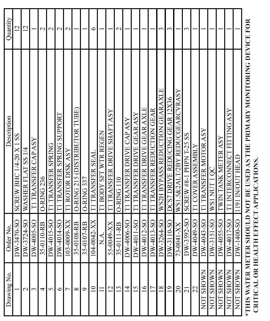
19 9. Replacement Parts pg. 18
20 pg. 19
21 pg. 20
22 pg. 21
23 pg. 22
24 pg. 23
25 pg. 24
26 pg. 25
27 pg. 26
28 10. Troubleshooting Problem Possible Cause Solution No Display on PC Board No power at electric outlet Repair outlet or use working outlet Control valve power adapter not plugged into outlet or power cord end not connected to PC board Verify that cord is plugged in and that proper voltage is being delivered to PC board connection connection Improper power supply Verify proper voltage is being delivered to PC board Defective power adapter Replace Power Adapter Defective PC Board Replace PC Board PC Board does not display correct time of day Display does not indicate that water is flowing. Refer to instructions for how the display indicates water is flowing (pg 13) Control valve regenerates at wrong time of day Power Adapter Plugged into electric outlet controlled by light switch Tripped breaker switch and/ or GFI switch Power outage Defective PC board Bypass valve in bypass position (Figure 23) Meter is not connected to meter connection on PC board Restricted/stalled meter turbine Meter cable wires are not installed securely into three pin connector Defective meter Defective PC Board Power outage Time of day not set correctly Time of regeneration set incorrectly Control valve set at on 0 (immediate regeneration) Control valve set at dely (delayed and/or immediate) Use uninterrupted outlet Reset breaker switch and/ or GFI switch Reset time of day. If PC board has battery back-up present, the battery may be depleted. See page 12 for instructions on how to change the time. Replace the battery. Replace PC Board, reprogram PC Board Turn bypass handles to place bypass in service position Connect meter to three pin connection labeled METER on PC board Remove meter and check for rotation or foreign material Verify meter cable wires are installed securely into three pin connector labeled METER Replace meter Replace PC Board, reprogram PC Board Reset time of day. If PC board has battery back-up present, the battery may be depleted. See front cover and drive assembly drawing for instructions. Reset to correct time of day Reset regeneration time Check programming setting and reset to dely (for a delayed regen time) Check programming setting and reset to NORMAL (for a delayed regen time) pg. 27
29 10. Troubleshooting (2) Problem Possible Cause Solution Time of day flashes on and off Power outage Reset time of day. If PC board has battery back-up present, the battery may be depleted. See page 12 for instructions on how to change the time. Replace the battery. Control valve does not regenerate automatically Broken drive gear or drive cap assembly Replace drive gear or drive cap assembly when the REGEN button Broken Piston Rod Replace piston rod is depressed and held. Defective PC Board Replace PC Board Control valve does not regenerate automatically but does when the REGEN button is depressed and held. Hard or untreated water is being delivered Bypass valve in bypass position Meter is not connected to meter connection on PC board Restricted/stalled meter turbine Incorrect programming Meter cable wires are not installed securely into three pin connector Defective meter Defective PC Board Bypass valve is open or faulty Media is exhausted due high water usage. Meter not registering Water quality fluctuation No or low level of salt in brine tank Control valve fails to draw in brine Insufficient water level in brine tank Damage seal/stack assembly Control valve body type and piston type mix matched Fouled resin Turn bypass handles to place bypass in service position Connect meter to three pin connection labeled METER on PC board Remove meter and check for rotation or foreign material Check for programming error Verify meter cable wires are installed securely into three pin connector labeled METER Replace meter Replace PC Board Fully close bypass valve or replace Check program settings or diagnostics for abnormal water usage Remove meter and check for rotation or foreign materials Test water and adjust program values accordingly Add proper amount of salt to tank Refer to pg. 23. Check refill setting in programming. Check refill flow control for restrictions or debris and clean or replace Replace seal/stack assembly Verify proper control valve body type and piston type match Replace resin pg. 28
30 10. Troubleshooting (3) Problem Possible Cause Solution Control valve uses too Improper refill settings Check refill settings (7.A) much brine Improper program settings Check program setting to make sure they are specific to the water quality and application needs Control valve regenerates frequently Check for leaking fixtures that may be exhausting capacity or system is undersized Residual salt is being delivered to service Excessive water in brine tank Control valve fails to draw in brine Water running to drain Low waste pressure Incorrect injector size Restricted drain line Improper program settings Plugged injector Drive cap assembly not tightened in properly Damaged seal/stack assembly Restricted or kinked drain line Plugged backwash flow controller Missing refill flow controller Injector is plugged Faulty regenerant piston Brine line connection leak Drain line restriction or debris cause excess back pressure Drain line too long or too high Low water pressure Power outage during regeneration Damage seal/stack assembly Piston assembly failure Drive cap assembly not tightened properly Check incoming water pressure. Water pressure must remain at minimum of 25 psi Replace injector with correct size for the application Check drain line for restriction or debris and clean Check refill setting Remove injector and clean or replace Re-tighten the drive cap assembly Replace seal/stack Check drain line for restrictions or debris and or un-kink drain line Remove backwash flow controller and clean or replace Replace refill flow controller Remove injector and clean or replace Replace regenerant piston Inspect brine line for air leak Inspect drain line and clean to correct restriction Shorten length or height Check incoming water pressure. Water pressure must remain at minimum of 25 psi Upon power being restored control will finish the remaining regeneration time. Reset time of day. If PC board has battery back-up present the battery may be depleted. See Front Cover and Drive Assembly drawing for instructions Replace seal/stack assembly Replace piston assembly Re-tighten the drive cap assembly pg. 29
31 11. Control Error Codes Problem Possible Cause Solution E1, Err-1001, Err-101 = Control unable to sense motor movement Motor not inserted full to engage pinion, motor wires broken or disconnected Disconnect power, make sure motor is fully engaged, check for broken wires, and make sure two-pin connector on motor is connected to the two pin connection on the PC board labeled MOTOR. Press NEXT and REGEN buttons for 3 seconds to resynchronize software with piston position or disconnect power supply from PC board for 5 seconds and then reconnect. E2, Err-1002, Err-102 = Control valve motor ran too short and was unable to find the next cycle position and stalled PC board not properly snapped into drive bracket Missing reduction gears Foreign material is lodged in control valve Mechanical binding Main drive gear too tight Improper voltage being delivered to PC board Properly snap PC board into drive bracket and then press NEXT and REGEN buttons for 3 seconds to resynchronize software with piston position or disconnect power supply from PC board for 5 seconds and then reconnect. Replace missing gears Open up control valve and pull out piston assembly and seal/stack assembly for inspection. Press NEXT and REGEN buttons for 3 seconds to resynchronize software with piston position or disconnect power supply from PC board for 5 seconds and then reconnect. Check piston assembly and seal/stack assembly, check reduction gears, check drive bracket and main drive gear interface. Press NEXT and REGEN buttons for 3 seconds to resynchronize software with piston position or disconnect power supply from PC board for 5 seconds and then reconnect. Loosen main drive gear. Press NEXT and REGEN buttons for 3 seconds to resynchronize software with piston position or disconnect power supply from PC board for 5 seconds and then reconnect. Verify that proper voltage is being supplied. Press NEXT and REGEN buttons for 3 seconds to resynchronize software with piston position or disconnect power supply from PC board for 5 seconds and then reconnect. pg. 30
32 11. Control Error Codes (2) Problem Possible Cause Solution E3, Err-1003, Err-103 = Control valve motor ran too long and was unable to find the next cycle position and stalled Motor failure during a regeneration Check motor connections. Press NEXT and REGEN buttons for 3 seconds to resynchronize software with piston position or disconnect power supply from PC board for 5 seconds and then reconnect. E4, Err-1004, Err-104 = Control valve motor ran too long and timed out trying to reach home position Foreign material built up on piston and stack assemblies creating friction and drag enough to time out motor Drive bracket not snapped in properly that reduction gears and drive gear do not interface Drive bracket not snapped in properly that reduction gears and drive gear do not interface Replace piston and seal/stack assemblies. Press NEXT and REGEN buttons for 3 seconds to resynchronize software with piston position or disconnect power supply from PC board for 5 seconds and then reconnect. Snap drive bracket in properly. Press NEXT and REGEN buttons for 3 seconds to resynchronize software with piston position or disconnect power supply from PC board for 5 seconds and then reconnect. Snap drive bracket in properly. Press NEXT and REGEN buttons for 3 seconds to resynchronize software with piston position or disconnect power supply from PC board for 5 seconds and then reconnect. Err-1006, Err-106, Err-116 = MAV/SEPS/NHBP/AUX MAV valve motor ran too long and unable to find the proper park position. MAV = Motorized Alternating Valve SEPS = Separate Source NHBP = No Hard Water Bypass AUX MAV = Auxiliary MAV Control valve programmed for ALT A or B, NHBP, SEPS, or AUX MAV without having a MAV or NHBP valve attached to operate that function MAV/NHBP motor wire not connected to PC board MAV/NHBP motor not fully engaged with reduction gears Foreign material built up on piston and stack assemblies creating friction and drag enough to time out motor Press NEXT and REGEN buttons for 3 seconds to resynchronize software with piston position or disconnect power supply from PC board for 5 seconds and then reconnect. Connect MAV/NHBP motor to PC board two-pin connection labeled DRIVE. Press NEXT and REGEN buttons for 3 seconds to resynchronize software with piston position or disconnect power supply from PC board for 5 seconds and then reconnect. Press NEXT and REGEN buttons for 3 seconds to resynchronize software with piston position or disconnect power supply from PC board for 5 seconds and then reconnect. Replace piston and seal/stack assemblies. Press NEXT and REGEN buttons for 3 seconds to resynchronize software with piston position or disconnect power supply from PC board for 5 seconds and then reconnect. pg. 31
33 11. Control Error Codes (3) Problem Possible Cause Solution Err-1007, Err-107, Err-117 = MAV/SEPS/NHBP/AUX MAV valve motor ran too short (stalled) while looking the proper park position. Foreign material is lodged in MAV/NHBP valve Check motor connections. Press NEXT and REGEN buttons for 3 seconds to resynchronize software with piston position or disconnect power supply from PC board for 5 seconds and then reconnect. MAV = Motorized Alternating Valve SEPS = Separate Source NHBP = No Hard Water Bypass AUX MAV = Auxiliary MAV Mechanical binding Check piston and seal/stack assemblies, check reduction gears, drive gear interface and check MAV/NHBP black drive pinion on motor for jammed into motor body. Press NEXT and REGEN buttons for 3 seconds to resynchronize software with piston position or disconnect power supply from PC board for 5 seconds and then reconnect. pg. 32
Trouble Shooting Guide for WS1 - WS2 Control Valves
 Trouble Shooting Guide for WS1 - WS2 Control Valves Page 2 Trouble Shooting Guide for WS1 - WS2 Control Valves 1. No Display on Troubleshooting TC control valves do not have meters so shaded ares are not
WS2H/ WS3 Error Codes
 WS2H & WS3 Troubleshooting Page 1 WS2H/ WS3 Error Codes Possible Errors Code Description 1001 No Encoder Pulses 1002 Unexpected Stall, Main Drive 1003 Run Time To Long, Main Drive 14001 Message Queue Full
Water Specialist EE Control Valve Programming and Cover Drawing Manual
 Water Specialist EE Control Valve Programming and Cover Drawing Manual Page 2 EE Man u al EE Man u al Page 3 Table of Contents EE Front Cover and Drive Assembly... 4 Regeneration and Error Screens, Button
Water Specialist EI Control Valve Programming and Cover Drawing Manual
 Water Specialist EI Control Valve Programming and Cover Drawing Manual Page 2 EI Man u al EI Man u al Page 3 Table of Contents EI Front Cover and Drive Assembly... 4 Regeneration and Error Screens... 5
Water Specialist CI Control Valve Programming and Cover Drawing Manual
 Water Specialist CI Control Valve Programming and Cover Drawing Manual Page 2 CI Man u al CI Man u al Page 3 Table of Contents CI Front Cover and Drive Assembly...4 OEM General Instructions...5 OEM Cycle
Water Specialist PR Control Valve Programming and Cover Drawing Manual
 Water Specialist PR Control Valve Programming and Cover Drawing Manual Page 2 PR Man u al PR Manual Page 3 Table of Contents PR Front Cover and Drive Assembly...4 OEM General Programming Instructions...5
Water Specialist CK and EQ Control Valve Programming and Cover Drawing Manual
 Water Specialist CK and EQ Control Valve Programming and Cover Drawing Manual Page 2 CK and EQ Manual CK and EQ Manual Page 3 Table of Contents CK Front Cover and Drive Assembly...4 OEM General Programming
Superior Water And Air
 Superior Water And Air 80-974-9090 800-974-7638 OWNERS MANUAL Model 32-CL990 & 48-CL990 General Information Congratulations on having purchased a quality and well built Superior Water Softener. On a normal
UF Series. Membrane Filtration System. Model CCUF-844
 UF Series Membrane Filtration System Model CCUF-8 TABLE OF CONTENTS Pre-installation Instructions for Dealers...3 Bypass Valve.... Installation....5 Programming Procedures... Start-up Instructions...3
TTV Series. Softening Water System. Installation, Operation and Maintenance Manual. Revised 01/17/13
 TTV Series Softening Water System Installation, Operation and Maintenance Manual CAUTION: Read and Follow all safety rules and operating instructions before first use of product. DEALER NAME: DEALER PHONE
SIMPLEX PREMIUM WATER SOFTENER INSTALLATION AND USER GUIDE
 SIMPLEX PREMIUM WATER SOFTENER INSTALLATION AND USER GUIDE 1 TABLE OF CONTENTS 1) Installation... 2 1.1) Pre-installation instructions... 2 1.2) General Installation and Service Warnings... 2 1.3) Site
Signature Series. Duplex Softener Service Manual
 Signature Series Duplex Softener Service Manual Control Start-Up Procedures System Overview Softener Slave Unit #2 (Forward Flow) Shuttle Valve Master Softener Slave Unit #1 (Reverse Flow) Connection to
Installation Instructions & Owner s Manual. Omega Series Metered Water Softeners
 Installation Instructions & Owner s Manual Omega Series Metered Water Softeners TABLE OF CONTENTS Preinstallation Instructions for Dealers............................3 Bypass Valve................................................3-4
Impression Series. Installation Instructions & Owner s Manual. Metered Water Softeners
 Installation Instructions & Owner s Manual Impression Series Metered Water Softeners For Models: IM-844DUPURE IM-948DUPURE IM-1044DUPURE IM-1054DUPURE IM-1248DUPURE IM-1354DUPURE For Cabinet Models: IMC-835DUPURE
Evolve ES Series. Water Softeners. For Models: ES-844 ES-948 ES-1044 ES-1248 ES-1354
 Evolve ES Series Water Softeners For Models: ES-8 ES-98 ES-0 ES-8 ES-5 TABLE OF CONTENTS Preinstallation Instructions for Dealers... Bypass Valve... Installation...5-6 Programming Procedures...7-8 Operating
Impression Plus Series
 Impression Plus Series Metered Water Softeners For Certified Models: IMP-844 IMP-948 IMP-1044 IMP-1054 IMP-1248 IMP-1354 Certified Cabinet Models: IMPC-835 IMPC-935 IMPC-1035 TABLE OF CONTENTS Pre-Installation
Impression Plus Series
 Impression Plus Series Metered Water Softeners For Certified Models: IMP-844 IMP-948 IMP-044 IMP-054 IMP-248 IMP-354 Certified Cabinet Models: IMPC-835 IMPC-935 IMPC-035 TABLE OF CONTENTS Pre-Installation
CareSoft. Series. Metered Water Softeners. For Models: UCS-844 UCS-948 UCS-1044 UCS-1054 UCS-1248 UCS-1354
 CareSoft Series Metered Water Softeners For Models: UCS-8 UCS-98 UCS-0 UCS-05 UCS-8 UCS-5 TABLE OF CONTENTS Pre-Installation Instructions for Dealers... Bypass Valve.... Installation.... 5-7 Programming
Evolve ES Series. Water Softeners. For Models: ES-844 ES-948 ES-1044 ES-1248 ES-1354
 Evolve ES Series Water Softeners For Models: ES-844 ES-948 ES-1044 ES-1248 ES-1354 TABLE OF CONTENTS Preinstallation Instructions for Dealers.................................. 3 Bypass Valve.......................................................
Owner s Manual HELLENBRAND, INC.
 Owner s Manual Manufactured by: HELLENBRAND, INC. 404 Moravian Valley Road Waunakee, Wisconsin 53597-2509 Phone: 608-849-3050 Fax 608-849-7398 Web: www.hellenbrand.com Email: info@hellenbrand.com 800160
Impression Plus Series
 Impression Plus Series Metered Water Softeners For Certified Models: IMP-8 IMP-98 IMP-0 IMP-05 IMP-8 IMP-5 Certified Cabinet Models: IMPC-85 IMPC-95 IMPC-05 TABLE OF CONTENTS Pre-Installation Instructions
Impression Plus Series Sanitizer Plus Series
 Impression Plus Series Sanitizer Plus Series Twin Water Softeners For Models: IMP-8TW IMP-0TW IMP-05TW IMP-5TW IMP-65TW IMP-665TW IMPRC-05TW IMPRC-5TW ASP-0TW ASP-05TW ASP-5TW ASP-65TW ASP-665TW ASP-0TW
Superior Water And Air OWNER S MANUAL Model 32-CL770 & 48-CL770
 Superior Water And Air 80-974-9090 800-974-7638 OWNER S MANUAL Model 32-CL770 & 48-CL770 GENERAL INFORMATION Congratulations on having purchased a quality and well built Superior Water Softener. On a normal
Water Specialist igen Control Valve Programming and Cover Drawing Manual
 Water Specialist igen Control Valve Programming and Cover Drawing Manual Page 2 igen Man u al igen Man u al Page 3 Table of Contents igen Front Cover and Drive Assembly...4 WS1 igen Drive Cap Assembly,
Sanitizer Plus Series. Water Conditioners
 Sanitizer Plus Series Water Conditioners TABLE OF CONTENTS Preinstallation Instructions for Dealers............................3 Bypass Valve................................................3-4 Installation..................................................5-6
AQT-56SE ELECTRONIC SERIES PROGRAMMING MANUAL CONTROL VALVES
 AQT-56SE ELECTRONIC SERIES PROGRAMMING MANUAL TABLE OF CONTENTS General Residential Installation 3 AQT-56SE Keypad 4 Control Operation 5 Master Programming - Setting the Time of Day 6 - Setting the Regeneration
SmartChoice. Gen II itwin. Water Conditioning System. Installation, Operation, and Maintenance Manual. Installation, Operation, and Maintenance Manual
 SmartChoice TM Gen II itwin Water Conditioning System > > CLOCK REGEN NEXT Installation, Operation, and Installation, Operation, and 7785 East US Hwy 36 Avon, IN 46123 (317) 272-3000 (800) 447-5582 For
UF Series. Twin Membrane Filtration System. Model CCUF-844TW
 UF Series Twin Membrane Filtration System Model CCUF-844TW TABLE OF CONTENTS Pre-Installation Instructions for Dealers...3 Bypass Valve....4 Installation....5 Programming Procedures...7 Start-up Instructions...9
Value Super Filter Max Installation Manual
 Value Super Filter Max Installation Manual Barrie, Ontario, Canada, L4N 4Y8 www.excaliburwater.com EXCALIBUR VALUE SUPER FILTER MAX INSTALLATION MANUAL INSTALLATION PROCEDURES: The Value Super Filter Max
Owner s Filter Manual. ProMate 6.0 Iron Curtain Junior Filter Manual
 ProMate 6.0 Iron Curtain Junior Filter Manual Owner s Filter Manual Manufactured by: Hellenbrand, Inc. 404 Moravian Valley Road Waunakee, Wisconsin 53597 Phone: 608 849-3050 Fax: 608-849-7398 Web: www.hellenbrand.com
OZONE ZENTEC CAPSULATE FILTER INSTALLATION AND USER GUIDE
 OZONE ZENTEC CAPSULATE FILTER INSTALLATION AND USER GUIDE 1 TABLE OF CONTENTS 1) Installation... 2 1.1) Pre-installation instructions... 2 1.2) General Installation and Service Warnings... 2 1.3) Site
TotalCare, CareSoft Elite. and CareSoft Pro. Series. Twin Water Softeners and Conditioners. For Models: TC1-TW TC2-TW CSE-TW CSP-TW CSERC-TW CSPRC-TW
 TotalCare, CareSoft Elite and CareSoft Pro Series Twin Water Softeners and Conditioners For Models: TC-TW TC-TW CSE-TW CSP-TW CSERC-TW CSPRC-TW TABLE OF CONTENTS Preinstallation Instructions for Dealers....
Series. Ion Pro and CareClear Pro. Water Filters. For Models: IPHS IPFE IPG IPCG-AN CCP CCP-AN
 Ion Pro and CareClear Pro Water Filters Series For Models: IPHS IPFE IPG IPCG-AN CCP CCP-AN TABLE OF CONTENTS Pre-Installation Instructions for Dealers... Bypass Valve.... 4 Installation....5-7 Programming
NUGEN Pure Water Systems Fusion XT. Installation Instructions and Owners Manual
 NUGEN Pure Water Systems Installation Instructions and Owners Manual XT-48, XT-60, XT-70, XT-70ER, and XT-90 XT-32C Page 2 Page 3 Table of Contents Your Water Test...3 Pre-Installation Instructions...4
UF Series. Membrane Filtration System. Model CCUF-844
 UF Series Membrane Filtration System Model CCUF-844 TABLE OF CONTENTS Pre-installation Instructions for Dealers...3 Flushing Schedule...3 Bypass Valve....4 Installation.... 5-7 Programming Procedures...
Sanitizer Plus Series
 Sanitizer Plus Series Water Conditioners For Models: ASP-0 ASP-05 ASP-5 ASP-0 ASP-05 ASP-5 TABLE OF CONTENTS Pre-Installation Instructions for Dealers... Bypass Valve.... Installation.... 5 Programming
BNT 85 /185 Valve Operation Manual
 BNT 85 /185 Valve Operation Manual Note: 1. Read all instructions carefully before operation. 2. Avoid pinched o-rings during installation by applying (provided with install kit) NSF certified lubricant
MASTER. Water Conditioning Corp. Installation and Operation Manual. MCA Combination Series Residential Units
 MASTER Water Conditioning Corp. Installation and Operation Manual MCA Combination Series Residential Units February 2011 Table of Contents Page No. Topic Description 1 Model # and Packaging Packaging Information
wd-2
 wd-2 wd-4 wd-5 wd-6 wd-7 wd-8 wd-9 wd-10 wd-11 wd-12 wd-13 Part # Tank Size ( DxH ) Media Volume (ft3) Service Flow Rate (GPM) WD SP35BFJCT 10 x44 1.0 6.0 WD SP46BFJCT 10 x54 1.5 9.0 WD SP56BFJCT 10 x54
H-125 HE SERIES. Owner s Manual HIGH EFFICIENCY SYSTEM. Manufactured by: HELLENBRAND, INC. Web:
 H-125 HE SERIES HIGH EFFICIENCY SYSTEM Owner s Manual p/n 800679 Rev. C Updated 10/02/18 2016-2018 Manufactured by: HELLENBRAND, INC. Web: www.hellenbrand.com Email: info@hellenbrand.com This owner s manual
Owner s Manual. H151 HE - High Efficiency Water Softening System
 H151 HE - High Efficiency Water Softening System Owner s Manual Manufactured by: HELLENBRAND, INC. 404 Moravian Valley Road Waunakee, Wisconsin 53597-2509 Web: www.hellenbrand.com Email: info@hellenbrand.com
Water Specialist 1.5, 2 and 2 QC Control Valve Drawings and Service Manual
 Water Specialist.5, and QC Control Valve ings and Service Manual HYDROCARBONS SUCH AS KEROSENE, BENZENE, GASOLINE, ETC., MAY DAMAGE PRODUCTS THAT CONTAIN O-RINGS OR PLASTIC COMPONENTS. EXPOSURE TO SUCH
INSTALLATION, OPERATING AND SERVICE MANUAL
 INSTALLATION, OPERATING AND SERVICE MANUAL ECONO-mist WATER SOFTENER Demand Regeneration 7-LMC56-75B 7-LM56-75B 7-LM56-100B 7-LM56-150B 7-LM56-200B Congratulations on purchasing your new Lancaster Water
AQT-275 SERIES SERVICE MANUAL CONTROL VALVES
 AQT-275 SERIES CONTROL VALVES SERVICE MANUAL Table of Contents General Residential Installation 3 Valve Start-up Procedures 4 Regeneration Cycle Program Setting Procedures 5 Water Conditional Diagrams
ProMate EcoMax Duo Twin Alt
 ProMate EcoMax Duo Twin Alt Owner s Manual Manufactured by: HELLENBRAND, INC. 404 Moravian Valley Road Waunakee, Wisconsin 53597 Web: www.hellenbrand.com Email: info@hellenbrand.com 800662 Rev A. 11/12/15
Water Specialist 1 Control Valve Series Model: WS Control Valve Series Model: WS1.25
 Water Specialist 1 Control Valve Series Model: WS1 1.25 Control Valve Series Model: WS1.25 Operation and Instruction Manual for OEM Only. Please Note: This operation and instruction manual is for the training
Impression Series Impression Plus Series
 Impression Series Impression Plus Series Water Filters For Models: IMS-05 IMS-8 IMS-5 IMFE-05 IMFE-8 IMFE-5 IAG-05 IAG-8 IAG-5 IACG-05AN IACG-8AN IACG-5AN IMBF-0 IMBF-05 IMBF-5 IMBF-0MAN IMBF-05MAN IMBF-5MAN
OWNER S MANUAL FOR ALL GREENSAND SYSTEMS
 OWNER S MANUAL FOR ALL GREENSAND SYSTEMS THIS MANUAL IS TO BE LEFT WITH THE OWNER OF THE EQUIPMENT FOR REFERENCE AND PURPOSES AND TECHNICAL GUIDANCE. IT IS STRONGLY RECOMMENDED THAT QUALIFIED DEALER SERVICE
Water Specialist WS2H and WS3 Control Valve Drawings and Service Manual
 Water Specialist WSH and WS Control Valve Drawings and Service Manual HYDROCARBONS SUCH AS KEROSENE, BENZENE, GASOLINE, ETC., MAY DAMAGE PRODUCTS THAT CONTAIN O-RINGS OR PLASTIC COMPONENTS. EXPOSURE TO
MGTE Series 1 1/2 Metered & Time Clock
 INSTALLATION, OPERATION, AND MAINTENANCE MANUAL MGTE Series 1 1/2 Metered & Time Clock COMMERCIAL WATER CONDITIONERS COMPLETE FOR FUTURE REFERENCE: MODEL NO: SERIAL NO: DATE INSTALLED: DEALER: Marlo Incorporated
Water Specialist 1 Control Valve Series Model: WS Control Valve Series Model: WS1.25
 Water Specialist 1 Control Valve Series Model: WS1 1.25 Control Valve Series Model: WS1.25 Operation and Instruction Manual for OEM Only. Please Note: This operation and instruction manual is for the training
General Operation. To set Time of Day. To set Time of Regeneration / Backwash
 1 General Operation When the system is operating one of two displays will be shown: time of day or days until the next regeneration. Pressing UP or DOWN will toggle between the two choices. To set Time
IWT 565 Series Valve Operation Manual
 IWT 565 Series Valve Operation Manual Note: 1. Read all instructions carefully before operation. 2. Avoid pinched o-rings during installation by applying (provided with install kit) NSF certified lubricant
Water Specialist 1 Control Valve Series Model: WS1CS 1.25 Control Valve Series Model: WS1.25CS
 Water Specialist 1 Control Valve Series Model: WS1CS 1.25 Control Valve Series Model: WS1.25CS Operation and Instruction Manual for OEM Only. Please Note: This operation and instruction manual is for the
Manual for Operation & Maintenance Of Metered Carbon Filter
 Industry Leader in RO Expertise and Membrane Applications since 1983 Manual for Operation & Maintenance Of Metered Carbon Filter for Models: W-G744EM W-G844EM W-G940EM W-G1054EM W-G1252EM W-G1354EM W-G1465EM
Installation and Operations Manual
 Excalibur Water Systems 3.0 High Capacity Superflow Series QUADPLEX Water Softener Installation and Operations Manual 142 Commerce Park Drive, Units M-O, Barrie ON L4N 8W8 www.excaliburwater.com Water
or OWNER S MANUAL MODEL R
 www.superiorwaterandair.com 801-974-9090 or 800-974-7638 OWNER S MANUAL MODEL 48-1000R Table of Contents Introduction...Page 1 Flow Diagrams...Page 3 The Electro-mechanical Timer Programming...Page 4 Extra
Water Specialist 1.5" CC Control Valve Programming and Drawings Manual
 Water Specialist 1.5" CC Control Valve Programming and Drawings Manual Page 2 WS 1.5 CC Man u al WS 1.5 CC Man u al Page 3 OEM General Instructions The control valve offers multiple procedures that allow
Model 7000XTR. Service Manual. IMPORTANT: Fill in Pertinent Information on Page 3 for Future Reference
 Model 7000XTR Service Manual IMPORTANT: Fill in Pertinent Information on Page 3 for Future Reference Table of Contents Job Specification Sheet 3 Water Softener Control Valve 4 Valve Installation and Start-Up
Water Specialist 1 Control Valve Series Model: WS1CI 1.25 Control Valve Series Model: WS1.25CI
 Water Specialist 1 Control Valve Series Model: WS1CI 1.25 Control Valve Series Model: WS1.25CI Operation and Instruction Manual for OEM Only. Please Note: This operation and instruction manual is for the
65 Series. Valve Operation Manual
 65 Series Valve Operation Manual Note: 1. Read all instructions carefully before operation. 2. Avoid pinched o-rings during installation by applying (provided with install kit) NSF certified lubricant
Owner s Manual AMERICAN AQUA Saline, MI (734) Howell, MI (517) Adrian, MI (517)
 Howell, MI (517) Adrian, MI (517)") Owner s Manual 2008-2009 AMERICAN AQUA Saline, MI (734)429-5070 Howell, MI (517)546-1750 Adrian, MI (517)265-8000 www.americanaqua.com This owner s manual is designed to assist owners and installers with
Owner s Manual 2008-2009 AMERICAN AQUA Saline, MI (734)429-5070 Howell, MI (517)546-1750 Adrian, MI (517)265-8000 www.americanaqua.com This owner s manual is designed to assist owners and installers with
Installation Instructions & Owner s Manual LINDYSPRING LCR Series II Water Conditioners
 Installation Instructions & Owner s Manual LINDYSPRING LCR Series II Water Conditioners 115 N.W. Van Buren Topeka, KS 66603 Phone: 785-234-5551 Toll-free: 800-880-2022 Toll-free Fax: 800-269-3478 TABLE
STORM. ProMate-6.0 Iron Curtain Storm Series
 STORM ProMate-6.0 Iron Curtain Storm Series Owner s Filter Manual Manufactured by: HELLENBRAND, INC. 404 Moravian Valley Road Waunakee, Wisconsin 53597 Web: www.hellenbrand.com Email: info@hellenbrand.com
ADVANCE. Backwashing Filters and Tannin Filter. Installation Instructions & Owner s Manual
 ADVANCE Backwashing Filters and Tannin Filter Installation Instructions & Owner s Manual Ta b l e o f Co n t e n t s : Preinstallation Instructions Page 1 Bypass Valve Page 1-2 Installation Page 3-4 Sulfur
GF Series Water Softener
 GF Series Water Softener INSTALLATION, OPERATION, AND MAINTENANCE MANUAL COMPLETE FOR FUTURE REFERENCE: MODEL NO: SERIAL NO: DATE INSTALLED: DEALER: 8-569 G&F R2 LIMITED WARRANTY FOR WATER CONDITIONERS
Owner s Manual. Manufactured by: HELLENBRAND, INC. 404 Moravian Valley Road Waunakee, Wisconsin
 System for Automatic Discharge Management - U.S. Patent No. 9,862,619 Method of Water Discharge Management - U.S. Patent No. 9,346,689 B2 Owner s Manual Manufactured by: HELLENBRAND, INC. 404 Moravian
WATER SOFTENER SERIES DAY TIMER INSTALLATION & OPERATING INSTRUCTIONS. Serial No :
 WATER SOFTENER SERIES 500 12 DAY TIMER INSTALLATION & OPERATING INSTRUCTIONS Model : Serial No : AS0922-E.. Manufacturer and Supplier of FILTRATION & WATER TREATMENT PRODUCTS for commercial, industrial
WS1TC Series Installation and Operation Manual
 WS1TC Series Installation and Operation Manual Table of Contents Installation... 3 Bypass Valve... 4 Start-up Instructions... 6 General Information... 7 User Displays/Settings... 8 Installer Displays/Settings...
Iron Blaster System Owner s Manual
 Iron Blaster System Owner s Manual CANADIAN ADDRESS 92 Commerce Park Dr. Unit #2 Barrie, ON L4N 8W8 Canada www.waterdepot.com IMPORTANT: Do not make any adjustments to these units, they are factory set.
Watco Pro Series Water Conditioner
 Watco Pro Series Water Conditioner Operation & Maintenance Manual Marketed Exclusively By: Lee Supply Corp. 6610 Guion Road Indianapolis, IN 46268 800-873-1103 Page 2 Quick Reference Chart GENERAL OPERATION
Water Specialist WS2H and WS3 Control Valve Manual
 Water Specialist WS2H and WS3 Control Valve Manual HYDROCARBONS SUCH AS KEROSENE, BENZENE, GASOLINE, ETC., MAY DAMAGE PRODUCTS THAT CONTAIN O-RINGS OR PLASTIC COMPONENTS. EXPOSURE TO SUCH HYDROCARBONS
WATER SOFTENER SEMI AUTOMATIC INSTALLATION & OPERATING INSTRUCTIONS. Serial No :
 WATER SOFTENER SEMI AUTOMATIC INSTALLATION & OPERATING INSTRUCTIONS Model : Serial No : SAS0922.. Manufacturer and Supplier of FILTRATION & WATER TREATMENT PRODUCTS for commercial, industrial and residential
AQT-56 POWERFLO SERIES SERVICE MANUAL CONTROL VALVES
 AQT-56 POWERFLO SERIES SERVICE MANUAL Table of Contents Products Checking List 3 General Residential Installation Check List 4 AQT-56ST Softener Timer Control Valve Start-up Procedures 5 AQT-56FT Filter
7-LX B 7-LX B 7-LX B 7-LX B 7-LX B
 ESTATE SERIES INSTALLATION, OPERATING AND SERVICE MANUAL ELECTRONIC WATER SOFTENER WITH THE ¼ X-FACTOR CONTROL VALVE PROGRAMMED FOR PRE-FILL BRINING OPTION 7-LX5-00B 7-LX5-50B 7-LX5-00B 7-LX5-300B 7-LX5-00B
TotalCare Series. Water Conditioners
 TotalCare Series Water Conditioners TABLE OF CONTENTS Preinstallation Instructions for Dealers............................3 Bypass Valve................................................3-4 Installation..................................................5-6
ProFloSE. Downflow Brining Service Manual. IMPORTANT: Fill in pertinent information on page 2 for future reference.
 ProFloSE Downflow Brining Service Manual IMPORTANT: Fill in pertinent information on page 2 for future reference. Job Specification Sheet Job Number Model Number Water Test Capacity Of Unit Max. Per Regeneration
Water Specialist 1 Control Valve Series Model: WS1EI 1.25 Control Valve Series Model: WS1.25EI
 Water Specialist Control Valve Series Model: WSEI.25 Control Valve Series Model: WS.25EI Operation and Instruction Manual for OEM Only. Please Note: This operation and instruction manual is for the training
TABLE OF CONTENTS. System Information...3. Pre-Installation Instructions...3. Installation Instructions Control Information...
 2401 SOFTENER VALVE The 2401 valve has been certified according to NSF/ANSI 44 by the Water Quality Association for material safety and structural integrity only. TABLE OF CONTENTS System Information...3
Model WS1 Demand. Operation & Maintenance Manual. 114 Vista Parkway Avon, IN New Aqua L.L.C.
 Model WS1 Demand Operation & Maintenance Manual 114 Vista Parkway Avon, IN 46123 317-272-6721 2008 New Aqua L.L.C. Page 2 Quick Reference Chart GENERAL OPERATION When the system is operating one of two
Installation and Operations Manual
 Excalibur Water Systems 2.0 HIGH CAPACITY SUPER FLOW SERIES DUPLEX WATER SOFTENER Installation and Operations Manual 142 Commerce Park Drive, Units M-O, Barrie ON L4N 8W8 www.excaliburwater.com 2.0 High
Commercial Softeners
 Commercial Softeners Product Index Page General System Specifications 35 Fleck Commercial Valve Configurations 36 Fleck 9500 1-1/" Systems 37 Fleck 850 1-1/" Systems 38 Fleck 3150 " Systems 39 Fleck 900
Water Specialist WS1TT Drawings and Service Manual
 Water Specialist HYDROCARBONS SUCH AS KEROSENE, BENZENE, GASOLINE, ETC., MAY DAMAGE PRODUCTS THAT CONTAIN O-RINGS OR PLASTIC COMPONENTS. EXPOSURE TO SUCH HYDROCARBONS MAY CAUSE THE PRODUCTS TO LEAK. DO
Service and Installation Guide
 Service and Installation Guide TM by AdEdge Technologies Inc. Medallion Series Arsenic Removal Systems Models: POE 5 1252 POE 7 1354 POE 10 1465 Arsenic Treatment Solutions Designed by: AdEdge Technologies,
5600 Control Valve. Bypass Piping Boss Inlet & Outlet. Distributor Tube and basket. Brine Well. Brine Line. Over-Flow (Optional) $1.
 $1.") Brine Well Distributor Tube and basket Safety-Cut Off (Optional) $8.00 extra Air Check Assembly Over-Flow (Optional) $1.00 extra 5600 Control Valve Gravel (Optional) Bypass Piping Boss Inlet & Outlet Brine
Brine Well Distributor Tube and basket Safety-Cut Off (Optional) $8.00 extra Air Check Assembly Over-Flow (Optional) $1.00 extra 5600 Control Valve Gravel (Optional) Bypass Piping Boss Inlet & Outlet Brine
Water Specialist 1 Control Valve Series Model: WS Control Valve Series Model: WS1.25
 Water Specialist Control Valve Series Model: WS.25 Control Valve Series Model: WS.25 Operation and Instruction Manual for OEM Only. Please Note: This operation and instruction manual is for the training
3200ET TIMER. Service Manual. IMPORTANT: Fill in pertinent information on page 2 for future reference.
 3200ET TIMER Service Manual IMPORTANT: Fill in pertinent information on page 2 for future reference. Installation And Start-Up Procedures Timer Programming Water Hardness System Capacity Regeneration Time
WS1 & 1.25 Man u al. Introduction. The following general warnings and the specifications in Table 1 must appear in the OEM s System Manual.
 Page 4 WS1 & 1.25 Man u al Introduction This manual is about a control valve to be used on water softeners or water filters. The manual is designed to aid water treatment equipment manufacturers in the
INSTALLATION, OPERATING AND SERVICE MANUAL ELECTRONIC WATER SOFTENER TIME CLOCK MODEL FEATURING THE 2002S VALVE
 INSTALLATION, OPERATING AND SERVICE MANUAL ELECTRONIC WATER SOFTENER TIME CLOCK MODEL FEATURING THE 00S VALVE 7-LECT-4 7-FESLECT-4 7-LET-4 7-FESLET-4 7-LET-3 7-FESLET-3 7-LET-45 7-FESLET-45 7-LET-60 7-FESLET-60
Problem and Solutions Manual
 Problem and Solutions Manual By Caden Bird Table of Contents Table of Contents... iii Introduction... 5 Identifying the Problem... 7 Taking Apart the Valve... 13 Various Problems and Solutions... 23 Putting
Panel Operation Quick Reference Guide
 Panel Operation Quick Reference Guide Manual Regeneration (Backwash) Note:. If you need to initiate a manual regeneration, either immediately, or tonight at the preprogrammed time (typically 2 a.m.), complete
5900e Carbon Filter Installation & Start-Up Guide
 Clean Water Made Easy www.cleanwaterstore.com 5900e Carbon Filter Installation & Start-Up Guide Thank you for purchasing a Clean Water System! With proper installation and a little routine maintenance
6700XTR Upflow. Service Manual. IMPORTANT: Fill in Pertinent Information on Page 3 for Future Reference
 6700XTR Upflow Service Manual IMPORTANT: Fill in Pertinent Information on Page 3 for Future Reference IMPORTANT: Fill in Pertinent Information on Page 3 for Future Reference Table of Contents Job Specification
Water Specialist 1 Control Valve Series Model: WS1TC 1.25 Control Valve Series Model: WS1.25TC
 Water Specialist Control Valve Series Model: WSTC.25 Control Valve Series Model: WS.25TC Operation and Instruction Manual for OEM Only. Please Note: This operation and instruction manual is for the training
Rayne Guardian Water Conditioner This manual contains information on setting the controller and normal operating maintenance required by the owner
 R Water Conditioning Rayne Guardian Water Conditioner This manual contains information on setting the controller and normal operating maintenance required by the owner Model RG1250 Owner s Manual R4043
2400VS SERIES. Technical Manual. A Division of Aquion, Inc.
 2400VS SERIES Technical Manual A Division of Aquion, Inc. Table of Contents Introduction... Page 1 Technical Specifications... Page 2 Flow Diagrams... Page 3 Injector & Flow Control Selection... Page 4
Water Specialist WS1TT Drawings and Service Manual
 Water Specialist 2nd Tank Connection Port Treated Water Outlet Untreated Water Inlet In/Out Head 2nd Tank Connection Port Control Valve Proper installation shown above. See page 2 for issues that arise
Chemical Free Iron Sulphur Filtration System Owner's Operation and Maintenance Manual
 Aerobica PDAF-1 054 Chemical Free Iron Sulphur Filtration System Owner's Operation and Maintenance Manual Water Quality Control Systems Limited, 605 Denison Street, Markham, Ontario Tel: 905-944-9465,
Fleck 2510 Manual Sediment Filter Installation & Start-Up Guide
 Clean Water Made Easy www.cleanwaterstore.com Fleck 2510 Manual Sediment Filter Installation & Start-Up Guide Thank you for purchasing a Clean Water System! With proper installation and a little routine
7500 Greensand Filter Installation & Start Up Guide
 Clean Water Made Easy www.cleanwaterstore.com 7500 Greensand Filter Installation & Start Up Guide Thank you for purchasing a Clean Water System! With proper installation and a little routine maintenance