( & $ ) ' $ & & & & ) (
|
|
|
- Reginald Russell
- 5 years ago
- Views:
Transcription

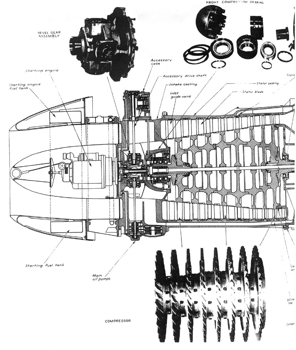
1 AS IS THE CASE with the airframe of the Me-262, the Junkers Jumo 004 axial flow gas turbine jet power plant is a compromise between design desire and available materials and production facilities. Outstanding evidence of compromises resulting from lack of materials is the fact that more than 7% of the air taken in is bled off for cooling purposes. Despite this, however, most engines were found to have a service life of about only 10 hr., against a design life of hr. Additional compromises are evident in the design, which shows that the production engineer undoubtedly hampered by lack of both plant facilities and adequate skilled labor has been as important a factor in its construction as was the designer. But the Germans had made real progress in overcoming materials difficulties, for just after they capitulated that development of a new alloy of excellent heatresistant qualities had made it possible to get up to 150 hr. service in actual flight tests, and up to 500 hr. on the test stand. A large unit, the 004 is 152 in. long from the intake to the tip of the exhaust; 30 in. in dia. at the skin around the six combustion chambers, with maximum diameter of the cowling reaching 34 in. The circular nose cowling is double skinned, the two surfaces being welded together near the leading edge and held in position by riveted channel shaped brackets. Diameter at the intake end is 20 in., the outer skin increasing to 31½ in., the inner to 21½. Inside the cowling is an annular gasoline tank which is divided into two sections, the upper being of ¾-gal. capacity feeding fuel to the starting engine, the lower of 3¼-gal. capacity, feeding starting fuel to the combustion chambers. The nose cowling attaches by eight screws in captured nuts to the annular-shaped combination oil tank and cooler. Having 3-gal. capacity, this tank has a baffle close to the inner surface so that as warm oil is fed in from the top it is cooled as it flows around to the bottom of annulus and the tank proper. The oil tank, in turn, is attached by 23 bolts on a flange to the aluminum alloy intake casting. This unit comprises the outer ring, with flanges on both front and rear faces,

2 four hollow streamlined spokes, and the inner ring. Moving back to the front of the unit, though, we find inside the nose cowling a fairing which looks just like a propeller spinner, increasing in size to 12 in. at the intake casting, leaving approximately 220 sq. in. intake area. This spinner houses the starting engine, a two-cylinder twocycle horizontally opposed gasoline engine which develops 10 hp. at 6,000 rpm. The starting engine has its own electric starting motor; and, for emergency, extending out to the front of the spinner is a cable starter similar to those found on outboard boat engines. The engine is 12½ in. long, 10 in. wide, 8¼ in. high, and weighs 36 lb. The starter engine is bolted to six studs in the bevel gear casting, which contains bears to drive the accessories. Each of these gears is carried by ball and roller bearings, with the drive shafts fitting into internally splined stub shafts on the bevels. There are two drive shafts extending through two of the hollow fairings of the intake casting, one going up to the accessory case which is mounted atop the intake casting, the other extending down to the main oil pumps, which are set inside the lower part of the intake casting. The bevel gear casting, also of aluminum alloy, is bolted to twelve studs set in a flange in the front face of the intake casting. The rear side of the intake casting's inner ring is cup-shaped, housing the front compressor bearing. This unit is comprised of three thrust races each with 15 bearings mounted in steel liners set in a light hemispheric-shaped housing which is kept in contact with the female portion of the intake housing by the pressure of ten springs held in place by a plate bolting to the intake casting. The outer bearing races are mounted in separate sleeves which fit on the compressor shaft. This design not only allows for preloading the bearings during assembly to ensure even distribution of thrust, but the bearing assembly can be left intact during disassembly simply by withdrawing the compressor shaft from the inner sleeve. Next in the fore-to-aft sequence ins the aluminum alloy stator casting, which is built in top and bottom halves held together longitudinally by eleven 3/8-in. bolts through flanges on each side, with attachment to the intake casting by 24 3/8-in. bolts through a heavy flange. Running the entire length of the bottom half of the casting are three.7-in dia. passages, one serving as part of the oil line leading to the rear compressor and turbine bearings, one connecting oil sumps (which are located in both intake and main castings), and one serving as part of the oil return line from a scavenge pump set in the rear turbine bearing housing. Just aft of the fourth compression stage in both halves of the stator casting is a slot, inside of which is a ring with a wedge-shaped leading edge pointing upstream and set to leave a.08-in. opening to bleed off air for part of the cooling system (which will be discussed later in a separate section.) Like the stator casting, the stator rings, which consist of inner and outer shroud rings and stator blades, are built as subassemblies, then bolted in place and locked by small tabs. Considerable variation, both in materials used and methods of construction, was found in this section. In early production units, for example, the inlet guide vanes and first two rows of stator blades were of stamped aluminum with airfoil profiles; and in assembly,

3 ends of the blades had been pushed through slots in the shroud rings and brazed in place. In other early engines, the third stator row varied both in material and method of attachment. In some cases it would be of aluminum, but without airfoil; in others it would be of steel with the ends turned to form flanges which were spot welded to the shroud rings. The remainder were stamped sheet steel, zinc coated. One late-production engine examined showed a combination of all the variations, with the inlet guide vanes and first two rows of stator blades of stamped aluminum, and the rest steel, indicating the Germans may have been swinging over from aluminum to steel exclusively. Apparently all the steel blades had been enameled, but this protective coating on the last row, where temperatures reached approximately 380 deg. C., appeared to have been burned off. Methods of attaching blades to shroud rings also varied. On the inlet guide vanes and first two rows, the ends of the blades had been pushed through slots in the shroud rings and brazed in place; the 3rd, 6th, and 7th rows had a weld all around the blade end; the 4th, 5th, and 8th row blade ends had been formed into split clips which were spotwelded to the shroud rings. The outer shroud rings are channel shaped with an angle bracket riveted to each end, this bracket in turn being bolted to a stud set in the casing just inside the mating flange. Inner shroud rings are flanged along the leading edge, with the exception of the 7th row, which is channel shaped. Except for the inlet guide vanes and the last row of stator blades, which act as straighteners, stator blades are arranged as impulse blading they are set at nearly zero stagger and simply serve as guides to direct the airflow into the rotor blades.


4 The compressor rotor is made up of eight aluminum disks held together by twelve bolts each through shoulders approximately at mid-diameter, with the entire unit being pulled together by a in. long,.705-in. dia. tie rod which has been estimated to have a stress of some 40,000 psi., with a force to pull the assembly together figured at about 16,000 psi. Diameters of the disks increase from the low to high pressure ends as follows: Stage 1, in., Stage 2, in., Stage 3, in., Stage 4, in., Stage 5, in., Stage 6, in., Stage 7, in., and Stage 8, in. To carry the compressor bearings there is attached to each end disk a steel shaft with an integral disk carrying a round-faced washer. This shaft goes through the disk and is

5 tightened by a nut so that the face of this washer (rounded to facilitate alignment) bears against the disk face. The flange on the rear shaft has six slots around its outer edge, into which fit projections on the rear disk. Thus torque is transmitted from the turbine to the rear compressor disk, and from there on to the other disks by the bolts previously noted as fastening the disks together, the torque being transmitted to the compressor unit around the faces, rather than through a central shaft. Compressor rotor blades, of which there are 27 in the first two stages, 38 in the rest, are all stamped aluminum with machined roots fitting into pyramid shaped slots in the rotor disk. Through the aft face of each blade root, directly under the blade trailing edge, is a small screw set longitudinally and extending into the disk. Tip stagger of the blades is about the same through the first six stages of compression, but increases in the last two. Chord of the blades decreases through the eight stages as follows: 1.95 in., 1,94; 1.34; 1.33; 1.30; 1.30; 1.24; and Blade profiles in the first two stages are very similar (possibly even designed to the same section), while the third stage has a thicker section. Stages 4, 5, and 6 have thinner sections (here, too, possibly the same), with about the same chord as Stage 3, while the last two stages, though set at greater pitch and having slightly narrower chord, have generally similar camber and profiles. Clearances between the rotor blades and the stator casting are.103 in. over the first three stages and.04 over the remaining five. Axial clearances between rotor disks and inner stator shroud rings range from.1 to.15 in., and axial clearances at roots between rotor and stator blades are.5 and.6 in. Backbone of the 004 is a complex aluminum casting which, in addition to providing the three engine attaching points, supports the compressor casing through 25 bolts the entire combustion chamber assembly, the turbine nozzle, the aft compressor bearing, the two turbine bearings and, through the combustion chamber casing, the entire exhaust system. Moreover, in the base of each of the six ribs supporting the combustion chambers, there are cored passages, five of which carry cooling air, one carrying lube oil. And, while the air passage area remains constant between the compressor and combustion chambers, the main casting changes the shape from annular to circular at the entrance to the chambers. In the front of the casting, at the tip of the last stator row, is an 18-3/8-in. die. ring with a serrated inner


6 surface fitting closely to serrations on the aft face of the last compressor disc. Air bleeding through the serrations is carried aft through cored holes in the casting to cool there front face of the turbine disk and, on hollow-bladed turbines, to cool the blades themselves. Just outside and in back of this ring are the fairings which divide the air and direct it into the individual combustion chambers. These fairings, in turn, are surrounded by a 28-in. o.d. ring with 25 bolt holes for attaching the compressor casing. Besides the bolt holes there are 18 openings, six of which carry the air bled off from the compressor on aft for exhaust system cooling, and twelve smaller ones which take cooling air around the combustion chambers. Around the outside of this ring, extending back to a heavy flange to


7 which the combustion chamber casing bolts, are twelve raised longitudinal ridges arranged in pairs. These have machined faces having four bolt holes and two aligning pins serving s the forward engine pickup points. With six such pickup points, the engine was designed for a wide variety of mountings. In the case of the Me-262 plates with collared nuts were fastened to the two on either side of the topmost unit. Overall length of the main casting is 37¼ in., with the previously mentioned ribs tapering down from the aft face of the ring structure to the central longitudinal member which has an 8¾-in. dia. ant the aft end. The aft compressor bearing, having 16 rollers, is set in the front of the main casting inside the serrated ring, the housing being attached to the casting by 14 bolts. The turbine thrust bearing is set inside the main casting, with the centerline of the balls 24-3/8 in. back of the front edge of the serrated ring, and the main turbine roller bearing is bolted into the rear end. Each of the six combustion chambers is built up of three major components having a combined weight of 19 lb. First, there is a mild steel outer casing, of 5¾ in. dia. at the entering end flaring out to 8-5/8 in., and having a length of 20-5/8 in. The front end has a collar with a rubber sealing ring which is pushed up against the aft face of the main casting to take care of air leakage and to compensate for the difference in casting and combustion chamber expansion. Fitting inside the front end of this casing is the flame tube, which has two main components the entry section and stub pipe assembly. The fore part of the entry section flares out somewhat as does the outer casing, and at the front end has a six-blade swirler. This unit is made of 22 gage mild steel with a black enamel coating. The stub pipe assembly is made up of ten flame chutes welded to a ring (which is welded by brackets to the rear end of the flame tubes and to a 4-in. dished baffle plate at the rear. To help direct air into the chutes, ½-in. circular baffle plates are riveted to the forward ring. Material of this unit is mild steel with an aluminized finish. Third major component of the combustion chamber is an 11-in. long 20-gage aluminized steel liner having a corrugated outer skin which permits cooling air to flow inside the outer casing. This liner fits into the aft end of the casing. The aft ends of the combustion chambers are bolted around flanges to a ring of six rings which fits over there rear end of the main casting. Ignition interconnectors between chambers are of but 15/32 in. dia., and starting plugs are provided in three of the six chambers. These elements, as are the fuel plugs, are enclosed in streamlined fairings. Surrounding the combustion chambers is a 16-gage mild steel double skinned casing having flanges welded at both ends that at the front end attaching by studs to the main casting; that at the rear attaching to the turbine inlet duct outer flange, the nozzle ring assembly flange, and the exhaust casing flange. Besides the bolt holes in the front flange, there are 24 of similar size, twelve leading to six ducts of 22-gage steel which carry the air bled from the fourth compressor stage through the combustion chamber casing, and twelve directing air around the combustion chambers. These ducts also help stiffen the skin, as it takes the weight of the entire exhaust system. Six large hand holes are cut in the casing just behind the flange. These give access for making minor adjustments to burners and the three ignition plugs. A little more than halfway aft around the combustion chamber casing is a heavy collar comprised of two channel shaped members, and inside the casing at this ring are six tie rids, connecting it to the main casting. Any one of these six units can serve as the aft engine pickup point; in the case of the Me-262 it is


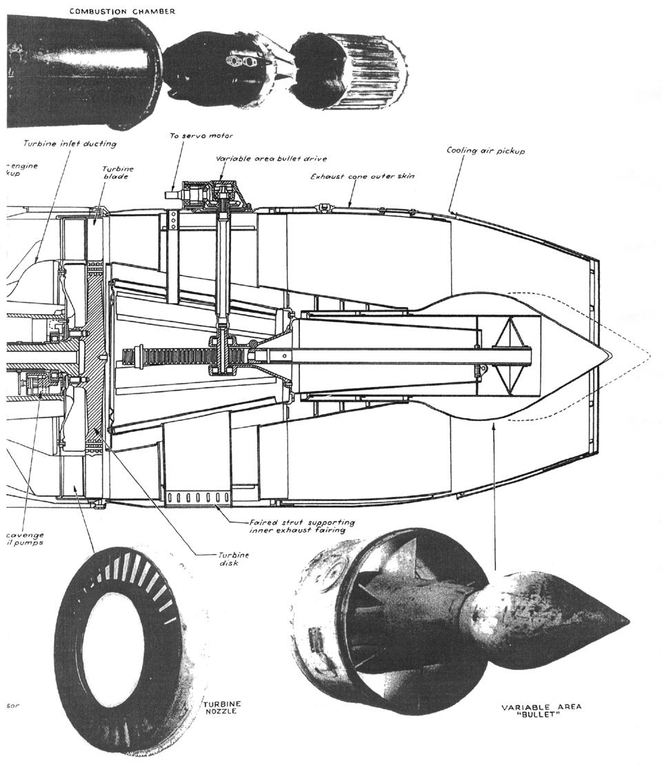
8 the top one. Ducting from the combustion chambers to the turbine nozzle changes the air passage from the six circles to annular shape. Attached to the combustion chambers by bolts, this 19-gage aluminized mild steel unit is made in two parts, the rear of which is welded to a heavy flange. Studded to this flange from the inner shroud ring of the turbine nozzle assembly are two mild steel diaphragm plates. These, in turn, are studded to the rear end of the main casting, and so support the inlet ducting and turbine nozzle ring. On the rear of the outer turbine inlet ducting a light flange mates with a flange on the rear of the combustion chamber casing. Thus the turbine inlet ducting, to which the combustion chambers are attached, is supported partly the diaphragms, and partly by the skin. Maintenance crews really take a beating as the result of the final design, for it is a major operation to get at the combustion chambers. First, the variable-area nozzle operating shaft must be removed so that the complete exhaust system assembly can be taken off. Then, unless special equipment is available, the engine must be placed upright on the turbine disk and burner pipes and ignition leads disconnected from the combustion chambers. Then the compressor casing-main casting joint can be broken and the whole front end lifted off. Next the rear compressor bearing assembly, torque tube, and locking ring can be removed and the main casting assembly removed when the nut on the front end of the turbine shaft is unscrewed. The rear diaphragm plates can then be removed and the turbine inlet ducting and combustion chamber assembly lifted off. Then the front diaphragm plate is removed and the turbine inlet ducting, with the combustion chamber assembly, lifted out of the casing. At this point, as one sweating engineer who did the job declared, Now, Bub, y'can take out the individual combustion chambers. An unusual feature of the 004's design is the use of hollow turbine nozzle blades through which cooling air is fed from the compressor via the main casting and supporting diaphragm plates. The two-part outer nozzle shroud ring is made of mild steel and both parts are welded to a ring that is joggled and flanged to mate with flanges through 36 bolts on the inlet ducting and the aft flange of the combustion chamber casing. In addition to the bolt holes the flange has 36 sets of three holes for cooling air passage. The 35 nozzles are made of austenitic sheet steel,.045 in. thick, bent to shape around a 1/16-in. radius to form the leading edge. Between the sheets at the trailing edge are spotwelded four wedge shaped spacers, 1 in. long and tapering from 1/8 to.020 in., leaving a.020-in. gap down the trailing edge through which the cooling air escapes. In assembly, the blade tips are closed, pushed through slots welded to the outer shroud ring, and the roots are pushed through slots in the inner shroud ring and spotwelded in place on the inner surface of the ring. To this ring, in turn, is welded a heavy, mild steel flange and second flanged ring, the two flanges picking up with the diaphragm plates which support the assembly from the rear of the main casting. Two types of 61-blade turbines are used. Originally both blades and disks were solid, later hollow blades and lighter disks were introduced at a saving of approximately 40 lb. The solid disks were of hardened chrome steel, taking stresses of about 15 tons at maximum rpm. Cooling is effected by spilling air bled back through the main casting against the disk face then up over the blade roots and out between the blades. The 12¼-oz. solid blades are
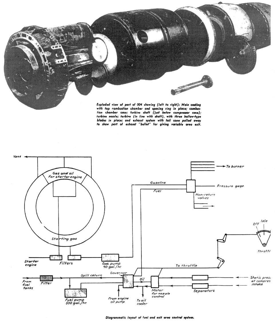
9 forged from an austenitic steel containing 30% nickel, 14% chrome, 1.75% titanium, and.12% carbon, corresponding closely to Tinidur, a Krupp alloy known before the war, and are attached by three machined lugs drilled to take two 11-mm. rivets each. Maximum centrifugal blade stresses have been estimated at 18,000 psi., and gas bending stresses at 2-4,000 psi. Study of the solid blades indicates that the roots didn't get much above 450 deg. C., due to the cooling air flow up from the disk, but near the center it appears the temperatures got up to about 750 deg. C. This applies to service models, not those previously mentioned as having given the longer flight and test-stand life. Disks for hollow blade turbines are of lighter material than the solid types and have attached, across the front face, a thin sheet flared out near the center. This picks up the cooling air and, via ridges on the disk, whirls it out toward the blade roots where it goes through two small holes drilled in the disk rim up through the blade and out the tip. Made of the same material as the solid blades, the hollow type are formed by deep drawing a disc through a total of 15 operations. In assembling the turbine, the blade roots are fitted over grooved stubs on the disk rim. Two small holes on each side take locating pins to hold the blades in place during assembly, but they take no stresses. With a silver-base flux in the grooves, the entire unit is put in an oven at deg. C., warmed for 20 min., then heated to about 1,050 deg. C. in 40 min., then cooled in still air at room temperature before hardening in a gas or air oven. Later production units have two rivets in the blade trailing edges near the tips, a modification made necessary by cracking caused by vibration. The turbine is attached by six studs to a short shaft carried no two bearings housed in the main casting. The front bearing is a single-race ball thrust, the rear a single-race roller type, and both are cooled by oil only Connection of the turbine and compressor is vi a heavy, internally splined coupling. The exhaust cone is made up of aluminized mild steel, and consists of two major components: outer fairing is double skinned, with cooling air bled from the compressor flowing between the skins to within 15-3/4 in. of the exit where the inner skin ends. Outside the other skin from there to the end is another skin, flared at the leading edge to scoop in cooling air. It is attached by spot welded corrugations. Attached to the outer fairing by six faired struts is the inner fairing, tapering from 19½ in. at the turbine end to 9¾. This unit houses a rack gear driven by a shaft entering through one of the struts which moves a bullet extending from its aft end. Actuating this bullet over its maximum travel of approximately 7-3/8 in. varies the exit area between 20 and 25%. It is set in retracted position for starting to give greater area and help prevent over-heating, then moved aft to decrease the area and give greater velocity for takeoff and flying. The movement is accomplished by a gear-type servo motor set near the accessory housing and connected by a long torque tube to gears set on the exhaust housing over one of the struts leading into the previouslymentioned rack gear. Originally the unit was supposed to operate automatically over small ranges at extremely high speed and altitudes to give maximum efficiency, but on some engines examined the necessary lines had been blanked off. The two-position operation is obtained through a mechanical linkage with the throttle so that the bullet moves aft at between 7,000 and 7,500 rpm. Since the necessary cooling system played a very important part in both the design and construction of the 004, it is felt best to note it briefly as a separate part of the study. It consists of three major stages, as follows: 1. Air bled off after the 4th compression stage. 2. Air taken off just after the last compression stage. 3. Air bled off between the compressor and combustion chambers. In Stage 1 the air is picked up by


10 the ring after the 4th compressor row and is directed into six cored passages in the stator casting, then at the combustion chamber casing it is divided so that some of the air goes through six ducts in the combustion chamber casing skin, some goes inside the casing and around the chambers themselves. That which goes into the ducts continues aft and, through small holes in the flanges, between the double skin of the exhaust cone outer fairing. Majority of the air goes straight on aft to the end of the inner skin, but some is taken through the six struts connecting the inner fairing into that unit to cool the rack gear and bullet. In Stage 2 the air goes through the serrations between the compressor and the main casting, into two of the six cored passages in the casting back to the turbine. Here, on the original engines, it was spilled against the face of the turbine disk and moved out to escape between the turbine blades. On engines with hollow blades, however, the air is ducted across the space between the two diaphragm plates supporting the turbine disc where it is picked up by ridges and forced up through the turbine blade roots out through the blade tips. Stage 3 cooling air, bled off between the compressor and combustion chambers, is ducted through three passages in the main casting to the space between the turbine nozzle-supporting diaphragms, then up through the turbine nozzle vanes and into the slip-stream through the trailing edges of the vanes. It is estimated that Stages 1 and 3 take approximately 3% each of the total air movement, and that Stage 2 probably takes at least half as much; thus better than 7% of the available flow is taken off because of a lack of higher heat-resistant alloys. Additional performance penalties are evident in the fact that ducting is necessary, complicating both the weight and production pictures. Air is not the only cooling medium, for the lubricating system too is employed. In this system, two gear pumps circulate lube oil to the front compressor bearing assembly, the accessory-drive bevel gears, and
11 the accessory gears. Another supplies oil to lubricate and cool the rear compressor and both turbine bearings, the latter two being sprayed and splashed, respectively. The two main pumps, mounted beneath the engine and driven from the bevel gears through a nose casting strut, deliver 190 gal./hr. each. The two-part scavenge unit is built into the turbine bearing housing and is driven by a gear cut into the sleeve which serves to return oil to the cooler. In level flight, one part of the unit, a 300 gal./hr. puma, returns oil through one of the cored passages in the main casting, then through a passage in the stator casting to the pump in the bottom of the intake casting. In climbs, the other part, a 90 gal./hr. gear pump, picks up the oil and feeds it into a common return line to the air-oil separator. Oil is returned from the main pump to the separator by a 300-gal./hr. driven by the same shaft as the delivery pumps. Two types of fuel are used on the 004: gasoline for starting and J-2 brown coal crud for running. The gasoline is carried in the lower part of the annular tank set in the nose cowling, and is automatically cut off after ignition at about 3,000 rpm. This is fed by an electrically driven pump delivering 80 gal./hr. at 28 psi. Near the end of the war it was found that centrifugal crude oil was also used as operating fuel. The main single-stage electricallydriven gear type pump has a maximum delivery of 500 gal./hr. at 1,000 psi. at 3,000 rpm. Most interesting of the accessories is the all-speed governor, a 17-lb. unit consisting basically of a centrifugal governor, oil pump and spill and throttle valves. In operation, oil goes through a passage to the pilot piston and is distributed to outer faces of either the spill or follow-up piston, depending on movement of the flyweights. Both the pistons move at the same time, adjusting the fuel spill to counteract changes in engine speed. The distance between the spill and follow-up pistons varies according to the flow of oil through the passages so that the spill piston action is a step-by-step operation controlled by the follow-up which returns to normal position after each step. A throttle valve is linked with the governor cam so that when the throttle is advanced the fuel flow increases and response is immediate. The governor then takes over and adjusts the engine speed to a predetermined value set by the position of the cam. Wt. (without cowl)...1,669 lb. Wt. (with cowl)...1,775 lb. Specific wt lb Thrust...1, lb. Pressure ratio... 3:1 Fuel consumption...2,720 2,745 lb./hr. Maximum speed...8,700 rpm. Idling speed...3,080 rpm. Idling speed fuel consumption lb./hr. Length in. Maximum dia in. Frontal area (cowled) sq. ft. Inlet guide Casting with oil pumps, filter...57 lb. Bevel gear assembly & drive shafts...18 lb. Gear box & drives...35 lb. Front compressor bearing assembly...25 lb lb. Stator csting & blades lb. Rotor with stub shaft & tie rod lb. Main casting & fittings lb. Utter casing & fittings lb. Rear compressor bearing assembly...6½ lb. Front turbine bearing assembly...7½ lb. Rear turbine bearing assembly & scavenger pumps...9 lb lb. 6 chambers burners, igniters, & interconnectors lb. Inlet ducting & joint rings...42 lb. Nozzle assembly...43 lb. Diaphragm plates...10 lb. Disk & blades (solid) lb. Shaft, sleeve, fittings...30 lb. Compressor coupling... 7 lb. Bullet assembly lb....1,430 lb. Oil tank...27 lb. Fuel pump... 9 lb. Governor...17 lb. Tachometer...1½ lb. Air-oil separator...4 lb. Bullet control servo motor...17½ lb. Drive shaft for bullet... 4 lb. Fuel filter... 2 lb. Fuel non-return valves... 1 lb. Throttle linkage... 7 lb. Misc. fittings & attachments...25 lb. Engine mount brackets...15 lb lb. Starter engine...36 lb. Gasoline tanks & supports...20 lb. Gasoline pump... 6 lb. Igniter coils... 3 lb. Net dry weight with starter...1,625 lb. Generator fittings...36 lb. Hydraulic pump... 8 lb....4 lb. Starter engine cowling... 4 lb. Starting fuel tank cowling...17 lb. Remainder of cowling...85 lb lb. Total dry weight, completely cowled engine...1,175 lb.
12

13
14
15
16
17
18 Edit ors note: This article was originally published in the October and November, 1945 issues, Volume 44, numbers 10 and 11, of Aviation magazine, published by McGraw- Hill Publishing Company of New York, NY, USA. This reconstruction is derived from microfilm. The source is University Microfilms International, Publication No. 364 (Aviation Week and Space Technology), Reel No. 21 (January 1945 December 1945). The source was a tightly bound volume, so that there is some distortion of the images, especially near the binding. It has not been practical to remove or compensate for all the distortions, so none of the illustrations in this reconstruction should be considered reliable sources as to fine details of shape, proportion or spatial relationship. The distortions are, in general, small, and should not detract from a general appreciation of arrangement and relationship. The editor has attempted to represent the original layout of the article, but there are some exceptions. Limitations in the compositing tools cause a difference in the text flow relative to the illustrations, compared to the original, so that some changes have been made, to compensate partially for that effect, and the tabular data have been removed from the flow of text and brought together on a single page after the text, partly to make them more accessible, and partly to sidestep problems with page layout. In addition, the original Part II article contained a foldout. Images from that sheet have been added at the end of the article. The images have considerable overlap, so that no information is lost, even though it is not practical to reproduce the original illustrations. This article was one in a series of design analyses published in Aviation during the war years, between May 1943 and November The subjects were the Bell P-39 Airacobra, Curtis C-46 Commando, Fleetwing BT-12, Douglas A-20 Havoc, Bristol Beaufighter (British), dehavilland Mosquito (British), North American P-51 Mustang, Lockheed P-38 Lightning, Focke-Wulf FW-190 (captured German), Boeing B-17 Flying Fortress, North American B-25 Mitchell (specifically, the B-25H and B-25J models), Mitsubishi Zeke 32 Hamp (captured Japanese), Consolidated Vultee B-24 Liberator, Fairchild C-82 Packet, and Messerschmitt Me-262 (captured German), with one article dealing specifically with the Me-262's Jumo 004 jet engine. Some of the analyses were authored by senior members of the design teams at the original manufacturers, while others were written by staff editors of Aviation magazine. The original articles were copyright to their respective sources the employers of the authors, following general practice of the time. This reconstruction is compilation copyright JL McClellan, 2004.
Metrovick F2/4 Beryl. Turbo-Union RB199
 Turbo-Union RB199 Metrovick F2/4 Beryl Development of the F2, the first British axial flow turbo-jet, began in f 940. After initial flight trials in the tail of an Avro Lancaster, two F2s were installed
THE WOLSELEY "VIPER" AERO ENGINE. (Hispano-Suiza W.4.A*)
") 13 THE WOLSELEY "VIPER" AERO ENGINE. (Hispano-Suiza W.4.A*) General description. The engine referred to in this article is the Hispano-Suiza 180 hp W.4.A* Aero Engine, as made by Wolseley Motors Ltd. The
13 THE WOLSELEY "VIPER" AERO ENGINE. (Hispano-Suiza W.4.A*) General description. The engine referred to in this article is the Hispano-Suiza 180 hp W.4.A* Aero Engine, as made by Wolseley Motors Ltd. The
Rolls-Royce Corporation 501-D22 COMMERCIAL ENGINE BULLETIN (CEB) Technical Publications Index
 Technical Publications Index") Corporation 501-D22 COMMERCIAL ENGINE BULLETIN (CEB) Technical Publications Index May 1. 2018 72-- ENGINE 72--1001 Engine -- Reduction Gear Prop Recommended No Later Than 11--01--66 No. 2, 11--15--68 Brake
Corporation 501-D22 COMMERCIAL ENGINE BULLETIN (CEB) Technical Publications Index May 1. 2018 72-- ENGINE 72--1001 Engine -- Reduction Gear Prop Recommended No Later Than 11--01--66 No. 2, 11--15--68 Brake
FUNCTION OF A BEARING
 Bearing FUNCTION OF A BEARING The main function of a rotating shaft is to transmit power from one end of the line to the other. It needs a good support to ensure stability and frictionless rotation. The
Jet Propulsion. Lecture-13. Ujjwal K Saha, Ph. D. Department of Mechanical Engineering Indian Institute of Technology Guwahati
 Lecture-13 Prepared under QIP-CD Cell Project Jet Propulsion Ujjwal K Saha, Ph. D. Department of Mechanical Engineering Indian Institute of Technology Guwahati 1 GE J79 Turbojet 2 Features Highly used
CLASSIFICATION OF ROLLING-ELEMENT BEARINGS
 CLASSIFICATION OF ROLLING-ELEMENT BEARINGS Ball bearings can operate at higher speed in comparison to roller bearings because they have lower friction. In particular, the balls have less viscous resistance
 Page 1 of 9 303-01C Engine 6.0L Diesel 2004 F-Super Duty 250-550/Excursion DESCRIPTION AND OPERATION Procedure revision date: 08/06/2003 Engine Printable View Engine Description The 6.0L diesel engine
SECTION AXIAL HVAC FANS
 SECTION 233413 - AXIAL HVAC FANS 1. PART 1 GENERAL 1.1. RELATED DOCUMENTS A. Drawings and general provisions of the Contract, including General and Supplementary Conditions and Division 01 Specification
Maintenance Information
 45528270 Edition 1 June 2007 Barring Motor T480 Series Maintenance Information Save These Instructions WARNING Always wear eye protection when operating or performing maintenance on this Barring Motor.
Bearings. Rolling-contact Bearings
 Bearings A bearing is a mechanical element that limits relative motion to only the desired motion and at the same time it reduces the frictional resistance to the desired motion. Depending on the design
Westingh'ouse Steam Turbines-I. B (Rev. 3) GOVERNOR, GOVERNING VALVE
 GOVERNOR, GOVERNING VALVE") Supersedes l. B. 697 (Rev. 2) Westingh'ouse Steam Turbines-I. B. 697 (Rev. 3) GOVERNOR, GOVERNING VALVE AND OIL PUMP This governor mechanism comprises a vertical shaft centrifugal weight governor a gear
Supersedes l. B. 697 (Rev. 2) Westingh'ouse Steam Turbines-I. B. 697 (Rev. 3) GOVERNOR, GOVERNING VALVE AND OIL PUMP This governor mechanism comprises a vertical shaft centrifugal weight governor a gear
Module 13: Mechanical Fuel Injection Diagnosis and Repair
 Terms and Definitions Parts of Injection Nozzles Types of Nozzle Valves Operation of an Injection Nozzle Fuel Flow Through the Unit Injector Optional Features on Fuel Injection Pumps Main Parts of a Distributor-Type
Rolls-Royce Corporation T56-A-14LFE COMMERCIAL ENGINE BULLETIN (CEB) Technical Publications Index
 Technical Publications Index") Corporation T56-A-14LFE COMMERCIAL ENGINE BULLETIN (CEB) Technical Publications Index November 1, 2017 72-- ENGINE 72--4001 Cancelled Prior to Publication A--72--4002 Engine -- Reduction Gear, Propeller
Corporation T56-A-14LFE COMMERCIAL ENGINE BULLETIN (CEB) Technical Publications Index November 1, 2017 72-- ENGINE 72--4001 Cancelled Prior to Publication A--72--4002 Engine -- Reduction Gear, Propeller
SNS COLLEGE OF TECHNOLOGY (An Autonomous Institution) Department of Automobile Engineering
 Department of Automobile Engineering") SNS COLLEGE OF TECHNOLOGY (An Autonomous Institution) Department of Automobile Engineering ACADEMIC YEAR 2015-16 FIFTH SEMESTER AU 302 AUTOMOTIVE ENGINE COMPONENTS DESIGN UNIT 2 CYLINDER, PISTON & CONNECTING
SNS COLLEGE OF TECHNOLOGY (An Autonomous Institution) Department of Automobile Engineering ACADEMIC YEAR 2015-16 FIFTH SEMESTER AU 302 AUTOMOTIVE ENGINE COMPONENTS DESIGN UNIT 2 CYLINDER, PISTON & CONNECTING
Maintenance Information
 16573347 Edition 2 February 2014 Air Grinder Series 88H Maintenance Information Save These Instructions Product Safety Information WARNING Failure to observe the following warnings, and to avoid these
ASSEMBLY. Transmission Automatic Transmission 5R44E and 5R55E. Special Tool(s)
") 307-01-1 Automatic Transmission 5R44E and 5R55E 307-01-1 ASSEMBLY Transmission Special Tool(s) Holding Fixture, Transmission 307-262 (T93T-77002-AH) Special Tool(s) Installer, Transmission Extension Housing
307-01-1 Automatic Transmission 5R44E and 5R55E 307-01-1 ASSEMBLY Transmission Special Tool(s) Holding Fixture, Transmission 307-262 (T93T-77002-AH) Special Tool(s) Installer, Transmission Extension Housing
60-65 Falcon, Comet & Ranchero Coil Spring IFS
 60-65 Falcon, 62-65 Comet & 62-65 Ranchero Coil Spring IFS All engine installations with this front end will require a rear sump oil pan. 289-302 Small Block Ford Motors Milodon rear sump pan holds 7 quarts
FLANGE. Flanges used for
 FLANGE FLANGE Flanges with rating class designations 150, 300, 400, 600, 900, 1500, and 2500 in sizes NPS 1 2 through NPS 24 ASME B16.5: Pipe Flanges and Flanged Fittings (NPS 24 ) ASME B16.47: NPS 26
SECTION D Engine 6.0L Diesel
 303-01D-i Engine 6.0L Diesel 303-01D-i SECTION 303-01D Engine 6.0L Diesel CONTENTS PAGE DESCRIPTION AND OPERATION Engine... 303-01D-2 303-01D-2 Engine 6.0L Diesel 303-01D-2 DESCRIPTION AND OPERATION Engine
Transmission Overhaul Procedures-Bench Service
 How to Assemble the Lower Reverse Idler Gear Assembly Special Instructions In 1996 Eaton changed the reverse idler system design. In the nut design, the reverse idler bearing was lubricated through a hole
11 - Fairings. Fairings. February XLF Page 11-1
 11 - Fairings Fairings February 2003 11-XLF Page 11-1 11 - Fairings This Page Intentionally Left Blank Page 11-2 11-XLF February 2003 11 - Fairings Contents 11.0 - Chapter Preface... 11-4 11.0.1 - Parts
Seabee Annual/100-Hour Inspection
 Date Completed Seabee Annual/100-Hour Inspection ENGINE Mechanic s Initials 1 Drain engine oil and check for foreign material 2 Check oil screen for proper rotation or looseness 3 Safety Oil Plug 4 Refill
4.2 WATER PUMP (GEAR CASE MOUNTED AND LATER) (GCM)
 (GCM)") SERIES 60 SERVICE MANUAL 4.2 WATER PUMP (GEAR CASE MOUNTED - 1991 AND LATER) (GCM) The centrifugal-type water pump circulates the engine coolant through the cooling system. The pump is mounted on the rear
SERIES 60 SERVICE MANUAL 4.2 WATER PUMP (GEAR CASE MOUNTED - 1991 AND LATER) (GCM) The centrifugal-type water pump circulates the engine coolant through the cooling system. The pump is mounted on the rear
Rolls-Royce Corporation M250-C20R COMMERCIAL ENGINE BULLETIN (CEB) Technical Publications Index
 Technical Publications Index") Rolls-Royce Corporation M250-C20R COMMERCIAL ENGINE BULLETIN (CEB) Technical Publications Index January 2, 2018 72-4001 Engine Conversion, 250 -C20R/2 to 250 -C20R/1 72-4002 Prior To Publication 72-4003
Rolls-Royce Corporation M250-C20R COMMERCIAL ENGINE BULLETIN (CEB) Technical Publications Index January 2, 2018 72-4001 Engine Conversion, 250 -C20R/2 to 250 -C20R/1 72-4002 Prior To Publication 72-4003
ENGINE & WORKING PRINCIPLES
 ENGINE & WORKING PRINCIPLES A heat engine is a machine, which converts heat energy into mechanical energy. The combustion of fuel such as coal, petrol, diesel generates heat. This heat is supplied to a
TORQUE CONVERTER. Section 2. Lesson Objectives. 6 TOYOTA Technical Training
 Section 2 TORQUE CONVERTER Lesson Objectives 1. Describe the function of the torque converter. 2. Identify the three major components of the torque converter that contribute to the multiplication of torque.
PYRTE. Building The Front Axle, Fork and Steering
 PYRTE Building The Front Axle, Fork and Steering The front axle on this traction engine is a very simple affair, in that it is a rectangular steel rod, sat on edge, with a pivot in the centre, which is
SPECIFICATIONS TEST AND ADJUSTMENT SPECIFICATIONS SPECIFICATIONS ENGINE FD620D, K SERIES
 ENGINE FD620D, K SERIES SPECIFICATIONS SPECIFICATIONS TEST AND ADJUSTMENT SPECIFICATIONS Engine Oil Pressure Sensor Activates............................... 98 kpa (14.2 psi) Oil Pressure While Cranking
COMPONENT IDENTIFICATION
 This CFMI publication is for Training Purpose Only. The information is accurate at the time of compilation; however, no update service will be furnished to maintain accuracy. For authorized maintenance
SECTION 4 - FUEL SYSTEMS AND CARBURETION
 SECTION - FUEL SYSTEMS AND CARBURETION FUEL SYSTEMS - - - - - - - - - - - - - - - - - - - - - - - - - - - - - - - - - - - - - - - - - - - - - - - - - - - - - - - - - - - - - -62 FUEL PUMP - - - - - - -
1964 1/2-70 Mustang Torque Arm Rear Suspension Installation Instructions
 1964 1/2-70 Mustang Torque Arm Rear Suspension Installation Instructions 1-800-984-6259 www.totalcostinvolved.com Version 2 (c) 2008 Total Cost Involved Engineering, Inc. All Rights Reserved. Page 1 of
The engine cowling installation and firewall should be inspected and modified as specified in this Service Bulletin.
 Single Engine Service Bulletin August 25, 2008 TITLE ENGINE COWLING ALIGNMENT INSPECTION AND MODIFICATION EFFECTIVITY Model Serial Numbers 172R 17280001 thru 17280724 172S 172S8001 thru 172S8201 REASON
DISASSEMBLY AND ASSEMBLY
 307-01-1 Automatic Transaxle/Transmission 307-01-1 DISASSEMBLY AND ASSEMBLY Transaxle Special Tool(s) Dial Indicator Gauge With Holding Fixture 100-002 (TOOL-4201-C) Special Tool(s) Test Plate Screw Set,
FUSELAGE ASSEMBLY SECOND SECTION (of three)
") FUSELAGE ASSEMBLY SECOND SECTION (of three) 1 FRONT FLOOR ASSEMBLY The front floor assembly is fabricated from three pieces of the two ply pre-pregnated panel material supplied. The basic floor panel and
FUSELAGE ASSEMBLY SECOND SECTION (of three) 1 FRONT FLOOR ASSEMBLY The front floor assembly is fabricated from three pieces of the two ply pre-pregnated panel material supplied. The basic floor panel and
ENGINE MECHANICAL <134>
 11A-1 GROUP 11A ENGINE MECHANICAL CONTENTS GENERAL INFORMATION........ 11A-2.................. 11A-3 11A-2 The newly developed 1.1L 134910 engine features 3-cylinder, 12-valve, and double overhead
CHAPTER 6 POWERPLANT
 Section Title CHAPTER 6 POWERPLANT 6.000 Powerplant And Related Systems................................ 6.1 6.001 Introduction............................................ 6.1 6.002 Description.............................................
D9 & D9G Crawler S/n 66A1 to 66A3265
 Caterpillar Service Manual D9 & D9G Crawler S/n 66A to 66A65 Service Manual THIS IS A MANUAL PRODUCED BY JENSALES INC. WITHOUT THE AUTHORIZATION OF CATERPILLAR OR IT S SUCCESSORS. CATERPILLAR AND IT S
HUDSON MOTOR CAR COMPANY
 HUDSON MOTOR CAR COMPANY 1935-1942 Carburetor Tune-up Manual ( for Hudson and Terraplane Models) Index Carter W-1 Downdraft 1935-1942 1 Carter W-1 Vacumeter Type 1938 Hudson 4 Carter WA-1 Vacumeter Type
46RE, 46RH, 47RE, 47RH ZIP KIT
 46RE, 46RH, 47RE, 47RH ZIP KIT PART NUMBER 46-47RHE-ZIP QUICK GUIDE Parts are labeled here in order of installation. See other side of sheet for details on Zip Kit contents. installation Diagram 7 1 Separator
DrVanos.com Stage II Installation Instructions. Tool rental is available with the purchase of a vanos kit *See website for more info*
 DrVanos.com Stage II Installation Instructions Special Tools Needed: Camshaft locking tool TDC Crank pin Sprocket turning tool Tool rental is available with the purchase of a vanos kit *See website for
CHAPTER 10 TAIL ROTOR TABLE OF CONTENTS
 CHAPTER 10 TAIL ROTOR TABLE OF CONTENTS INTRODUCTION 3 GENERAL 3 HUB ASSEMBLY 3 TRUNION 4 YOKE ASSEMBLY 4 BEARING HOUSING 5 BLADES 5 STRUCTURE 5 BLADE MAJOR PARTS 7 PITCH-CHANGE MECHANISM 7 PITCH HORNS
AUTOMATIC TRANSMISSIONS Mitsubishi F3A20 Series TRANSMISSION APPLICATION TABLE
 Article Text ARTICLE BEGINNING AUTOMATIC TRANSMISSIONS Mitsubishi F3A20 Series APPLICATION TRANSMISSION APPLICATION TABLE Vehicle Application Transmission Model Colt 3-Speed (1990-94)... F3A21 Colt Vista
SD Bendix DD-3 & SD-3 Safety Actuators PUSH PLATE & SHAFT ASSY. LOCKPORT SERVICE DIAPHRAGM SEPARATOR LOCKING PISTON O-RING LOCKING PISTON
 SD-02-4600 Bendix DD-3 & SD-3 Safety Actuators AUXILIARY DIAPHRAGM SERVICE DIAPHRAGM SEPARATOR PUSH PLATE & SHAFT ASSY. LOCKING PISTON O-RING LOCKING PISTON LOCKPORT DRAIN SLOT RETURN SPRING CAP O-RING
Instruction Manual for HSPA Take-Up Units
 Installation Instruction Manual for HSPA Take-Up Units Warning: To ensure the drive is not unexpectedly started, turn off and lockout the power source before proceeding. Failure to observe these precautions
BRAKE SYSTEM Nissan 240SX DESCRIPTION BRAKE BLEEDING * PLEASE READ FIRST * BLEEDING PROCEDURES ADJUSTMENTS BRAKE PEDAL HEIGHT SPECS TABLE
 BRAKE SYSTEM 1990 Nissan 240SX 1990 BRAKE SYSTEMS Nissan Disc & Drum Axxess, Maxima, Pathfinder, Pickup, Pulsar NX, Sentra, Stanza, 240SX, 300ZX DESCRIPTION All brake systems are hydraulically operated
Chapter 2 How the Diesel Aircraft Engine Functions
 Chapter 2 How the Diesel Aircraft Engine Functions People who are familiar with the functioning of a gasoline aircraft engine need not have any difficulty in understanding how a high speed Diesel aircraft
ADVANCED TECHNOLOGY FOR AXIAL-FLOW FANS WITH VARIABLE PITCH CONTROL. Presented by:
 ADVANCED TECHNOLOGY FOR AXIAL-FLOW FANS WITH VARIABLE PITCH CONTROL Presented by: Aerodynamic Performance Figure is a typical performance field of a variable pitch axial flow fan, showing the shape of
ASSEMBLY INSTRUCTIONS
 ASSEMBLY INSTRUCTIONS FOR FORGED SUPERLITE BIG BRAKE FRONT HUB KIT WITH 3.00 DIAMETER VENTED ROTOR 968-969 FORD MUSTANG (DISC BRAKE SPINDLE ONLY) PART NUMBER GROUP 0-950 WARNING INSTALLATION OF THIS KIT
Maintenance Information
 16573370 Edition 2 February 2014 Air Grinder 99V Series Maintenance Information Save These Instructions Product Safety Information WARNING Failure to observe the following warnings, and to avoid these
Handout Activity: HA170
 Basic diesel engine components Handout Activity: HA170 HA170-2 Basic diesel engine components Diesel engine parts are usually heavier or more rugged than those of similar output gasoline engines. Their
CHAPTER 11 FLIGHT CONTROLS
 CHAPTER 11 FLIGHT CONTROLS CONTENTS INTRODUCTION -------------------------------------------------------------------------------------------- 3 GENERAL ---------------------------------------------------------------------------------------------------------------------------
Maintenance Information
 16573321 Edition 3 February 2014 Air Grinder Series 61H Maintenance Information Save These Instructions Product Safety Information WARNING Failure to observe the following warnings, and to avoid these
TC20 Chain Driven Power Take-Off Overhaul Instructions
 TC20 Chain Driven Power Take-Off Overhaul Instructions Table of Contents Section Page Introduction 4 Ordering Repair Parts 4 General Information 5 Special Tools 6 Disassembly See Page 2 Reassembly See
LUCAS HEADLAMP SWITCH - PR18/4B
 LUCAS HEADLAMP SWITCH - PR18/4B By the mid-fifties Miller had lost considerable ground to Lucas in the competition for the British motorcycle market and Vincents switched to Lucas when the Series D machines
SHAFT ALIGNMENT FORWARD
 Service Application Manual SAM Chapter 630-76 Section 24 SHAFT ALIGNMENT FORWARD One of the basic problems of any installation is aligning couplings or shafts. Therefore, this section will endeavor to
Chapter 71. Power Plant
 Chapter 71 Power Plant PAGE 1 Table of Contents Chapter Title 71-10-00 COWLING.................................. 3 71-20-00 ENGINE MOUNT............................ 5 71-20-01 Shock Mounts................................
FANS. By- T.M.JOARDAR
 FANS By- T.M.JOARDAR Contents 1. INTRODUCTION 2. PRINCIPLE OF WORKING 3. CLASSIFICATION OF FANS 4. FAN DESIGNATION 5. CONSTRUCTIONAL FEATURES 6. PARAMETERS FOR FANS 7. CONTROLS 8. ACCESSORIES 9. INTERLOCK
AN EXPLANATION OF CIRCUITS CARTER YH HORIZONTAL CLIMATIC CONTROL CARBURETER
 AN EXPLANATION OF CIRCUITS CARTER YH HORIZONTAL CLIMATIC CONTROL CARBURETER The Carter Model YH carbureter may be compared with a Carter YF downdraft carbureter with the circuits rearranged to operate
SECTION 3. EXHAUST SYSTEMS
 9/8/98 AC 43.13-1B 8-45. GENERAL. Any exhaust system failure should be regarded as a severe hazard. Depending upon the location and type of failure, it can result in carbon monoxide (CO) poisoning of crew
Jabiru J170/230/430/250/450 Constructors Manual. Pre-Paint>Fuselage>Undercarriage>Assemble main gear
 Objectives of this task: In this task you will assemble the main undercarriage legs, which includes fitting the axles, disc brakes and wheels and adjusting the brakes. Materials required: Cards # J8 Dual
MAN B&W ME Engine Description. Page 1 of 6. Frame Box
 ME Engine Description Page 1 of 6 Please note that engines built by our licensees are in accordance with MAN Diesel & Turbo drawings and standards but, in certain cases, some local standards may be applied;
CYLINDER HEAD OVERHAUL
 ENGINE OVERHAUL PROCEDURES - GENERAL INFORMATION -2011 Mercedes-... Page 1 of 20 CYLINDER HEAD OVERHAUL * PLEASE READ THIS FIRST * Examples used in this article are general in nature and do not necessarily
Signature Series A/F/X Body GM Installation Instructions Power Disc Conversion
 Signature Series A/F/X Body GM Installation Instructions Power Disc Conversion 64-72 A Body / 67-69 F Body / 62-74 X Body Your new disc brake conversion kit can be bolted up with standard hand tools. The
STEAM TURBINE MODERNIZATION SOLUTIONS PROVIDE A WIDE SPECTRUM OF OPTIONS TO IMPROVE PERFORMANCE
 STEAM TURBINE MODERNIZATION SOLUTIONS PROVIDE A WIDE SPECTRUM OF OPTIONS TO IMPROVE PERFORMANCE Michael W. Smiarowski, Rainer Leo, Christof Scholten, Siemens Power Generation (PG), Germany John Blake,
FAA approval has been obtained on technical data in this publication that affects airplane type design.
 Single Engine Service Bulletin January 28, 2008 TITLE ENGINE COWLING ALIGNMENT INSPECTION AND MODIFICATION EFFECTIVITY Model Serial Numbers 172R 17280725 thru 17281262 172S 172S8202 thru 172S10006 REASON
First, check and record the camber and caster readings, they will be adjusted later.
 First, check and record the camber and caster readings, they will be adjusted later. The caliper-mounting bosses are machined perpendicular to the spindle so they are an excellent place for the level.
Jabiru Aircraft Pty. Ltd. Final Inspection Checklist J200/400. Firewall forward components
 Jabiru Aircraft Pty. Ltd. Final Inspection Checklist J200/400 Registration No: Aircraft Checklist Pre Ground Test Model: Aircraft Serial No: Firewall forward components Propeller: Prop Size: 60 x 53 Other:
ENGINE, WITH CONTAINER: TURBOSUPERCHARGED, DIESEL, FUEL INJECTION, 90-DEGREE V TYPE, AIR-COOLED, 12-CYLINDER, ASSEMBLY;
 *TM 9-2815-200-35 DEPARTMENT OF THE ARMY TECHNICAL MANUAL DIRECT SUPPORT, GENERAL SUPPORT AND DEPOT MAINTENANCE MANUAL INCLUDING REPAIR PARTS AND SPECIAL TOOLS LISTS FOR ENGINE, WITH CONTAINER: TURBOSUPERCHARGED,
Performer Series Carburetor Rebuild Kit Catalog #1477 Models
 Please read these instructions carefully before attempting to rebuild your carburetor. Make sure to refer to your carburetor Owner s Manual for further information if need be. If you have any questions
Lycoming AIRCRAFT ENGINES. IO-540-AC1A5 Wide Series Flange Crankcase Model Engine PARTS CATALOG PC
 AIRCRAFT ENGINES IO-540-ACA5 Wide Series Flange Crankcase Model Engine PARTS CATALOG PC-5- November 008 Lycoming 5 Oliver Street Williamsport, PA 770 U.S.A. 570/33-8 IO-540-ACA5 PARTS CATALOG This illustrated
Module 6: Air Foundation Brakes
 Air Brakes Terms and Definitions Basic Components That Make Up Air Foundation Brakes Types of Air Foundation Brakes Parts of a Cam Foundation Brake Parts of a Wedge Foundation Brake Parts of a Disc Foundation
MAN Energy Solutions
 ME Engine Description Page 1 of 6 Please note that engines built by our licensees are in accordance with drawings and standards but, in certain cases, some local standards may be applied; however, all
NEUFORM 3-Blade-Variable Pitch Propeller R2 Series. Assembly and Maintenance Manual
 NEUFORM 3-Blade-Variable Pitch Propeller R2 Series for Rotax 912, 912S and 914 Manual control by hand lever (H) or electric constant speed control (ECS) Date: 28 April 2010 Your NEUFORM-Distributor: Table
HIGH PERFORMANCE TRANSMISSION PARTS Instructions. Line Pressure Booster Kit. TCC Control Plunger Valve Kit. Line Pressure Modulator Plunger Valve Kit
 Performance Pack Ford 4R100 Part No. HP-4R100-01 Line Pressure Booster Kit Line-to-Lube Pressure Regulator Valve Line Pressure Booster Kit Valve Sleeve O-Rings (2) TCC Control Plunger Valve Kit Front Lube/Drainback
Troubleshooting, Service Tips, And Major Improvements For Hydrostatic Transmissions (Special Edition){3200}
{3200}") Page 1 of 75 Troubleshooting, Service Tips, And Major Improvements For Hydrostatic Transmissions (Special Edition){3200} 943, 953, 963, 973 Loaders Introduction The hydrostatic transmissions used in 943,
Page 1 of 75 Troubleshooting, Service Tips, And Major Improvements For Hydrostatic Transmissions (Special Edition){3200} 943, 953, 963, 973 Loaders Introduction The hydrostatic transmissions used in 943,
Rotary Internal Combustion Engine: Inventor: Gary Allen Schwartz
 Rotary Internal Combustion Engine: Inventor: Gary Allen Schwartz 1 The following is a design for a circular engine that can run on multiple fuels. It is much more efficient than traditional reciprocating
Installation Instructions Pro Stick Shifter
 Installation Instructions Pro Stick Shifter Part Number 80701, 80702 & 80706 2012, 2010, 2008, 2001, 1998 by B&M Racing and Performance Products The B&M Pro Stick shifter #80701 and #80706 comes equipped
Lycoming Aircraft Engines Parts Catalog
 Aircraft Engines Parts Catalog IO-0-BG Wide Cylinder Flange Crankcase Model Engine Part No. PC-0- Oliver Street Williamsport, PA 770 Aircraft Engines Parts Catalog IO-0-BG Wide Cylinder Flange Crankcase
Power Flow System Extractor Exhaust System Installation Instructions Cessna 172, 175 TABLE OF CONTENTS
 Heading Power Flow System Extractor Exhaust System Installation Instructions TABLE OF CONTENTS Pages Introduction 3 Kit Contents Classic Tailpipes 4 Kit Contents Short Stack Tailpipes 5 Preparation 6 Removal
Norden. A Lancashire Mill Engine. Scale: 1:12
 Scale: 1:12 Neil M. Wyatt February 2009 Fig. 1: General Arrangement General Arrangement Sheet: 1 An Old Steam Engine DEAR SIR, In the ruins of an old mill at, near Rochdale, there is an old steam engine
Maintenance Information
 04581245 Edition 2 May 2014 Air Grinder, Die Grinder and Sander Series G2 (Angle) Maintenance Information Save These Instructions Product Safety Information WARNING Failure to observe the following warnings,
Local Option 206 Rules Manual Section 1 General Rules 1. Only stock Briggs & Stratton LO206 # engine will be allowed in this class.
 Local Option 206 Rules Manual Section 1 General Rules 1. Only stock Briggs & Stratton LO206 # 124332-8201engine will be allowed in this class. o All parts will be stock unaltered Briggs & Stratton Animal
A 1 SERVICE SPECIFICATIONS
 A1 A2 Clutch CLUTCH Specifications Pedal height (from asphalt sheet) Release point (from pedal stroke end position) Push rod play at pedal top Pedal freeplay Disc rivet head depth Disc runout Diaphragm
Air Management System Components
 AIR M anagement Sys tem Air Management System Components Air Management System Features Series Sequential The series sequential turbocharger is a low pressure/high pressure design working in series with
Illustrated Parts List to
 TYPE NUMBERS 0022 through 0035, 0040 through 0062, 0070, 0076,0100, 0102, 0120 through 0125, 0307, 0318,0320, 0326, 0340 through 0366, 0370 through 0378, 0382, 0385, 0390, 0391, 0394, 0398, 0402, Illustrated
HIGH PERFORMANCE TRANSMISSION PARTS Instructions. Line Pressure Booster Kit. TCC Control Plunger Valve Kit. Line Pressure Modulator Plunger Valve Kit
 Performance Pack Ford 4R100 Part No. HP-4R100-01 Line Pressure Booster Kit Line-to-Lube Pressure Regulator Valve Line Pressure Booster Kit Valve Sleeve O-Rings (2) TCC Control Plunger Valve Kit Front Lube/Drainback
Maintenance Information
 Form 16573321 Edition 1 July 2004 Air Grinder Series 61H Maintenance Information Save These Instructions Always wear eye protection when operating or performing maintenance on this tool. Always turn off
KWIK SHOP GENERAL PREDATOR RULES 2019
 GENERAL PREDATOR RULES 2019 These rules are intended to keep the engine as Stock Out Of The Box as possible. There are no gray areas. If they do not specifically state that something is allowed, it will
Front Suspension. Front Suspension Component Layout. NOTE: Without Dynamic Response version shown
 Published: Jan 25, 2005 Front Suspension Front Suspension Component Layout NOTE: Without Dynamic Response version shown 1 Flanged bolt (Upper arm forward bush) 2 Bush - forward (Upper arm) Page 1 of 9
Chevy Nova Pro-Touring Front Suspension Installation Instructions
 1962-1967 Chevy Nova Pro-Touring Front Suspension Installation Instructions 1-800-984-6259 www.totalcostinvolved.com 1 Pro-Touring Clip A-Arm Assembly Sway Bar Assembly Fender Panel Kit 8 7/16-20 * 1 ¼
ASSEMBLY INSTRUCTIONS FOR DYNALITE DRAG RACE FRONT HUB KIT WITH DIAMETER SOLID ROTOR PINTO / MUSTANG II
 ASSEMBLY INSTRUCTIONS FOR DYNALITE DRAG RACE FRONT HUB KIT WITH 0.75 DIAMETER SOLID ROTOR 97-978 PINTO / MUSTANG II (FIVE LUG CONFIGURATION ONLY)* PART NUMBER GROUP 0-03-B DISC BRAKES SHOULD ONLY BE INSTALLED
NZQA unit standard version 5 Page 1 of 6. Demonstrate knowledge of engine design factors and machining practices
 Page 1 of 6 Title Demonstrate knowledge of engine design factors and machining practices Level 4 Credits 20 Purpose People credited with this unit standard are able to demonstrate knowledge of engine design
STERNDRIVE UNIT 3 B GEAR HOUSINGS MR/ALPHA ONE/ALPHA ONE SS
 STERNDRIVE UNIT 3 B 23146 GEAR HOUSINGS MR/ALPHA ONE/ALPHA ONE SS Table of Contents Page Identification........................... 3B-1 Specifications.......................... 3B-1 Torque Specifications................
CONVENTIONAL ENGINE CONSTRUCTION
 CONVENTIONAL ENGINE CONSTRUCTION CYLINDER BLOCKS, HEADS, AND CRANKCASES The cylinder, or the engine block, is the basic foundation of virtually all liquid-cooled engines. The block is a solid casting made
TYPE E Main Valve Sizes 3 /8 through 12
 Technical Data SD 3001E PRINTED IN U.S.A. SD 3001E/9709 SPENCE ENGINEERING COMPANY, INC. 150 COLDENHAM ROAD, WALDEN, NY 12586-2035 A B TYPE E MAIN VALVE FACE TO FACE DIMENSIONS C D E DIMENSIONS (inches)
SECTION CENTRIFUGAL HVAC FANS
 SECTION 233416 - CENTRIFUGAL HVAC FANS 1. PART 1 GENERAL 1.1. RELATED DOCUMENTS A. Drawings and general provisions of the Contract, including General and Supplementary Conditions and Division 01 Specification
ASSEMBLY INSTRUCTIONS
 ASSEMBLY INSTRUCTIONS FOR DYNALITE PRO SERIES FRONT HUB KIT WITH.75 DIAMETER VENTED ROTOR 970-973 FORD MUSTANG (DRUM / DISC SPINDLE) PART NUMBER GROUP 0-905 WARNING INSTALLATION OF THIS KIT SHOULD ONLY
Next, set the bar level and tighten it down. Do this on both the driver and passenger sides.
 Next, set the bar level and tighten it down. Do this on both the driver and passenger sides. Using two tape measures, measure the outside width at the front and the rear of the tubes. The front dimension
Table of contents. Table of contents Repair manual
 Table of contents Table of contents 1. Introduction... 1 1.1. Safety precautions... 1 1.2. Symbols... 1 2. Main shaft and bearing... 3 2.1. Front bearing... 3 2.1.1. Front bearing disassembly... 3 2.1.2.
GM 4L80-E, 4L85-E SURE CURE KIT
 GM 4L80-E, 4L85-E SURE CURE KIT PART NUMBER SC-4L80E INSTALLATION GUIDE Parts are labeled here in order of installation. See page 2 for details on Sure Cure kit contents. See Sure Cure instruction booklet