Limit Switches 1-1 thru Safety Switches 2-1 thru Index 3-1
|
|
|
- Margery Strickland
- 5 years ago
- Views:
Transcription
1 Limit Switches - thru -6 Safety Switches - thru -0 Index 3-3 i


2 Industrial Limit Switches Basic Technical Concepts / 8385 / Miniature Industrial Limit Switches, Positive Opening / Industrial Limit Switches, Positive Opening / Miniature Pre-Cabled Limit Switches, Positive Opening / Pre-Cabled Limit Switches, Positive Opening / Miniature Limit Switches / / 8373 / / Automotive Limit Switches / Sealed Limit Switches / / 8358 Door Interlock Switches / / Manual Reset Positive Opening Miniature Limit Switches / 8384 Waterproof Limit Switch / / Cable Pull Limit Switches /6 /
3 Basic technical principles Introduction What is meant by a "position detector" is any device which needs to be operated by a member which exerts a physical force, in view of : - either the form which its operating device takes - or the considerable force needed to operate it The distinguishing features of position detectors are : - their high electrical performance capability - their excellent resistance to accidental impact - good protection against splashed or dripping water -a wide range of operating devices to allow the detectors to be adapted to a vast variety of mechanisms Construction Our detectors are designed to conform to international IEC recommendations and/or European standards (EN). Proof that a detector conforms to these standards or recommendations takes the form of a conformity declaration made by the manufacturer (drafted as indicated in guidance document ISO/IEC - EN 450-4). Characteristics in line with the general requirements of standards NFC 6340, IEC and EN Leakage paths and air gaps : IEC NFC Our position detectors which comply with IEC can be fitted to machine-tools and industrial machines complying with NFC 7930, IEC 04., EN6004 or VDE 3. Electrical characteristics Assigned working current (Ie): - the current level adopted as a basis for the operating conditions quoted for a detector, and for the life tests on it. Thermal rating (Ith): - the current the microswitch will withstand when not being operated electrically, for a temperature rise of not more than 60 C. Assigned insulation voltage (Ui): - the voltage adopted as a reference for the dielectric tests and leakage paths. It must be equal to or greater than the assigned working voltage. Categories of use (IEC ): - AC 5 for operating AC solenoids and electromagnets - DC 3 for operating DC solenoids and electromagnets Contact element designation (IEC ): -a letter and number which define the use category and the assigned working voltage and current For example, A 300 means : in category AC 5, a maximum working voltage of 300 V and 6 A at 0 V or 3 A at 40 V. Contact block electrical wiring diagram Form Za Form Zb Rules and regulations EC Directives Our detectors conform to the EC Low Voltage Technical Directive 73/3/EEC and can be used in accordance with the specifications of the Machinery Directive 89/39/EEC. Environmental conditions Temperature limits When they are used in the temperature range quoted, the mechanical and electrical characteristics of our position detectors will remain substantially unchanged. If you intend to use them outside this range, please consult us. Protective treatment The treatment given to our position detectors is suitable in the vast majority of applications. Parts made of steel are zinc-coated or painted according to their mechanical function. Further information is available on request. This treatment allows our detectors to be used under the following temperature and humidity conditions : T C Relative humidity % This treatment may thus be suitable for applications in tropical or equatorial climates where the equipment concerned is in an interior location sheltered from direct exposure to atmospheric conditions. Other types of reinforced protection are possible for resistance to very severe environments. Please enquire. Mounting requirements Electric shock protection. The user should observe the mounting instructions relating to the mode of protection against electric shocks defined in the IEC 536., EN NFC 0030 standards : Class I : earth circuit link. Protection via differential circuit-breaker. Class II : double insulation. Class III : very low safety voltage. Screw tightening torque : : Actuator tightening. to.5 Nm Plastic Metal body body : Head fixing screw 0.7 to 0.8 Nm 0.8 to Nm 3 : Body fixing screw 0.7 to 0.8 Nm 0.8 to Nm 4 : Fixing screw to.5 Nm Adjustment of rotary heads with momentary action to right and left : For series , 83 85, 83 86, , , (x 360 ) 4 3 Both contacts have the same polarity The contacts are electrically isolated Positive break contact operation (IEC , chapter 3) For contacts used in safety applications, limit switches, emergency stop devices, assurance that opening has occurred is essential (see IEC 04, EN6004). After each attempt, contact opening is checked by an impulse voltage test (500 V). Contact element : - Snap action contact This is characterized by tripping points and release points which cannot be confused. The speed at which the control devices moves is independent from the speed of the control device. This feature makes it possible to obtain satisfactory electrical performance even where the control device is moving at low speed. A: Total travel (TT) of the control device A B : Pre-travel (PT) until the contact element B F opens C : Release travel until the contact element closes 0 D : B-C = Differential travel C D F : Travel required to reach the positive opening point (POT) Degree of protection Under the IEC 59 or NFC 000 classification scheme, standards employ an IP code to define the degree or class of protection which a position detector provides against access to live components and against the entry of solid foreign bodies and the entry of water. st numeral Protection equipment provides against the entry of solid foreign bodies 0 (not protected) 4 diameter mm 5 protected against dust 6 sealed against dust nd numeral 0 (not protected) 4 splashed water 5 hosed water Protection for persons against access to dangerous parts (not protected) mm Ø wire mm Ø wire mm Ø wire Protection equipment provides against the entry of water 6 high-pressure hosed water 7 temporary immersion 8 prolonged immersion /
4 Mechanical characteristics Terminology Forces - Positions - Travel PT OT POT TT DT Travel Positions Forces Electrical Position of operating device circuit NC NO RP RP Rest position Position of the operating device when no external mechanical force is applied. Also described as "height at rest". PT TP Tripping point Position of the operating device in relation to its mounting (hole, face) at the moment when an operating force causes the snap action of the mechanism to trip. PT Pre-travel TP OT Distance between the rest position RP and the tripping point TP. OF OP OF Operating force Force which must be applied to the operating device to displace the rest position RP to the tripping point TP. OP Operating point POT Position of the operating device when the applied force has moved it to the point on its travel where mechanical and electrical operation of the detector can be relied on to occur. OT Operating travel Distance between the rest position RP and the operating point OP. POF POP TT POF Positive opening force Operating force applied to the operating device to cause the positive opening action to take place. POP Positive opening point Position of the operating device at the moment when a force produces the positive opening action. POT Positive opening travel Minimum movement of the operating device required to ensure that the opening contact is positively opened. TTF OL TTF Total travel force Force applied to the operating device to move it through its total travel. OL Overtravel limit Position of the operating device when the force applied has brought it to the effective end of its permitted travel without causing damage. TT Total travel DT Distance between the rest position RP and the overtravel limit OL. RRF RLP RRF Release force Level to which the operating force OF must be reduced to allow the mechanism to return to its release position RLP. RLP Release position Position of the operating device at the moment when the snap-action mechanism trips on its return to its original position. DT Differential travel Distance between the tripping point TP and the release position RLP. - Positive opening action : see IEC chapter 3,. N.B. : The max. and min. values quoted for each detector (min. operating force, max. total travel, etc.) are the maxima and minima users must allow for if they are to use our products under the proper conditions. /3


 - Current peak 000 A at 50 V a 0.5 < cos ϕ < 0.")
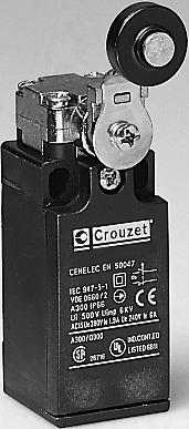
5 Limit switches "Series "EN Types Conform to the following standards : Thermoplastic IEC 536-, IEC , case with double CSA C. No. 4, EN 50047, insulation and EN , EN 6004-, metal actuator NFC 0030 class II for 83 head 850 Metal bodies and class I for actuator heads UL 508, VDE 0660/00. Degree of protection : Version : pole Function : Four-terminal double break contact element (form Zb) with positive opening NC contacts. The two moving contacts are electrically isolated from one another. Principle : Independent snap action contact NO + NC Dependent action NO + NC Break Before Make Electrical characteristics Assigned insulation voltage (Ui) : 500 V Thermal rating (Ith) : 0 A Use category : A300 - Q300 AC5 = 6A/50 V -.9 A / 380 V DC 3 = 3A/4 V Short circuit test (under IEC ) - Current peak 000 A at 50 V a 0.5 < cos ϕ < Short circuit protection (SCPD) : fuse 0 A gf - Electrical protection by internal earth terminal (83 85) Connections : Saddle washer and M 3.5 screw Max. wire cross-section : x.5 mm or x.5 mm Connection : For / NPT Approvals : UL listed A300 - Q300 - CSA A300 - Q300 NC + NO Control mechanisms - adjustable actuator heads 4 positions 90 Steel plunger Plunger with steel roller Lever with plastic vertical roller lateral Rotary head, momentary action to right and left () With lever and plastic roller Ø Ø 9 offset 40 offset 53 With adjustable lever and plastic roller Ø to 69.5 With adjustable polyamide rod actuator Flexible metal lever () Action either right or left according to position of head Sequence Independent snap action Dependent action Positive break operation Mechanical characteristics Minimum operating force Minimum total travel force Minimum positive opening force Minimum operating travel Minimum positive opening travel Differential travel Max. total travel N (oz.) N (oz.) N (oz.) mm (in.) mm (in.) mm (in.) mm (in.) Mechanical life (millions of operations) mini. Temperature Use C ( F) limits Stored C ( F) Degree of protection Weight Series Series Independent snap action NC + NO Dependent action NC + NO Independent snap action NC + NO Dependent action Ø 50 offset 47 offset 53.5 Ø offset 3.5 or 45 offset 46 adjustable offset g (oz.) g (oz.) (35.3) (4.3) 0,8 4,5F 6 mm 0,9 0,8 3 3,F 6 mm 5 (88.) 5 (.) 6 (.4).5 (.06) 6 (.4) (-3+76) (-40+76) 90 (3.) 70 (6) (35.3) (4.3) 0 3, 7,8F mm,5 0 3, 5,6 5,8F mm 5 (88.) 5 (.) 6 (.4).5 (.06) 6 (.4) (-3+76) (-40+76) 00 (3.5) 80 (6.3) (3.7) 0 (35.3) 0 6,5 5,5Fmm 3 0 6,5 9,5 F mm 0 (70.5) 5 (.) 6.5 (.47).5 (.06) 6 (.4) (-3+76) (-40+76) 00 (3.5) 80 (6.3) (3.7) 0 (35.3) 0 6,5 5,5Fmm 0 (70.5) 5 (.) 6.5 (.47) 3 0 6,5 9,5 F mm.5 (.06) 6 (.4) (-3+76) (-40+76) 05 (3.7) 80 (6.3) Other information For other contact types and accessories or special modes of operation : please consult us. For dimensions see page /8. Replacement contact block Part number Configurations Function SPDT <STD> SPDT Break before make SPDT Make before break NO DPST - Normally open NC DPST - Normally closed /4


 8cmN (40inoz) 8cmN (40inoz) 3 (0) 37cmN (5inoz) 37cmN (5inoz) 37cmN")
 75cmN (06inoz) 75cmN (06inoz) 75cmN (06inoz) 75cmN (06inoz) 75cmN (06inoz) 75cmN")
 -40+80(-40+76) 30 (4.6) 05 (7.")
 0º 75º 5-5+80(-3+76) -40+80(-40+76) 53 (5.4) 5 (7.")
 To order, specify : Standard products Standard products, non stocked Part number")
6 F F F F F F F F cmN (40inoz) 8cmN (40inoz) 8cmN (40inoz) 8cmN (40inoz) 8cmN (40inoz) 8cmN (40inoz) 8cmN (40inoz) 8cmN (40inoz) 3 (0) 37cmN (5inoz) 37cmN (5inoz) 37cmN (5inoz) 37cmN (5inoz) 37cmN (5inoz) 37cmN (5inoz) 37cmN (5inoz) 37cmN (5inoz) 4.5 (6) 75cmN (06inoz) 75cmN (06inoz) 75cmN (06inoz) 75cmN (06inoz) 75cmN (06inoz) 75cmN (06inoz) 75cmN (06inoz) 75cmN (06inoz) º 60º 60º 60º 60º 60º 60º 60º 60º 0º 75º (-3+76) (-40+76) 30 (4.6) 05 (7.3) 0º 75º (-3+76) (-40+76) 30 (4.6) 05 (7.3) 0º 75º (-3+76) (-40+76) 30 (4.6) 05 (7.3) 0º 75º (-3+76) (-40+76) 30 (4.6) 05 (7.3) 0º 75º (-3+76) (-40+76) 30 (4.6) 05 (7.3) 0º 75º (-3+76) (-40+76) 53 (5.4) 5 (7.93) 0º 75º (-3+76) (-40+76) 53 (5.4) 5 (7.93) 0º 75º (-3+76) (-40+76) 53 (5.4) 5 (7.93) 0º 75º (-3+76) (-40+76) 30 (4.6) 00 (7.) To order, specify : Standard products Standard products, non stocked Part number Example : Limit switch /5
 with positive opening NC contacts.")
 : 500 V Thermal rating (Ith) : 0 A Use")
 : fuse 0 A gf - Electrical protection by internal earth terminal Connections : Saddle washer and M 3.5 screw Max. wire cross-section : x.5 mm or.")
7 Limit switches "Series 83 86" EN 5004 Dependent Conform to the following standards : EN 5004, IEC , VDE 0660/00 UL 508, CSA C. No.4 IEC 536-, EN 6004-, NFC 0030 class I Degree of protection : Function : Four-terminal double break contact element (form Zb) with positive opening NC contacts. The two moving contacts are electrically isolated from one another. Principle : Independent snap action contact NO + NC Dependent action NO + NC Break before make Electrical characteristics : Assigned insulation voltage (Ui) : 500 V Thermal rating (Ith) : 0 A Use category : A300 - Q300 AC5 = 6A/50 V -.9 A / 380 V DC 3 = 3A/4 V Short circuit test (under IEC ) - Current peak 000 A at 50 V~0.5 < cos ϕ < Short circuit protection (SCPD) : fuse 0 A gf - Electrical protection by internal earth terminal Connections : Saddle washer and M 3.5 screw Max. wire cross-section : x.5 mm or.5 mm Connection : / NPT Approvals : UL listed A300 - Q300 - CSA A300 - Q300 Types action NC + NO Independent snap action NC + NO Control mechanisms - adjustable actuator heads 4 positions 90 Steel plunger Plunger with steel roller Lever with vertical plastic roller lateral Rotary head, momentary action to clockwise and/or anti-clockwise () Ø offset 43.5 With lever and plastic roller With adjustable lever and plastic roller 57 to 73 With adjustable polyamide rod actuator Flexible metal lever Independent snap action Sequence Positive break operation Ø 9 offset 56 offset 50.5 Ø 50 offset 57 Ø offset 36 or 48 offset 49 Ø 50 adjustable offset Dependent action ,7F 6 mm 0,9 0 3, 3,4F 6 mm ,4 8F mm,5 0 3,4 5,6 5,8F mm Mechanical characteristics Minimum operating force Minimum total travel force Minimum positive opening travel Minimum operating travel Minimum positive opening travel Differential travel Max. total travel N (oz.) N (oz.) N (oz.) mm (in.) mm (in.) mm (in.) mm (in.) 0 (35.5) (4.3) 5 (88.) 5 (.) 6 (.4).5 (.06) 6 (.4) 0 (35.5) (4.3) 5 (88.) 5 (.) 6 (.4).5 (.06) 6 (.4) 9 (3.7) 0 (35.3) 0 (70.5) 5 (.) 6.5 (.6).5 (.06) 6 (.4) 9 (3.7) 0 (35.3) 0 (70.5) 5 (.) 6.5 (.6).5 (.06) 6 (.4) Mechanical life (millions of operations) mini Temperature Use C (ºF) -5+80(-3+76) -5+80(-3+76) -5+80(-3+76) -5+80(-3+76) limits Stored C (ºF) (-40+76) (-40+76) (-40+76) (-40+76) Degree of protection Weight g (oz.) 305 (0.76) 35 (.) 30 (.8) 35 (.46) () Action either right or left according to position of head Accessories Cover with status indicator 4.30 V a c (supplied loose) 0 V a Replacement contact block Part number Configuration Function SPDT <STD> SPDT Break before make SPDT Make before break NO DPST - Normally open NC DPST - Normally closed 0 6,5 5,5Fmm 3 0 6,5 9,5 F mm 3 0 6,5 5,5Fmm 0 6,5 9,5 F mm Other information For other contact types and accessories or special modes of operation : please consult us. For dimensions see page /9. /6


 8cmN (40inoz) 8cmN (40inoz) 8cmN (40inoz) 8cmN (40inoz) 8cmN")
 37cmN (5inoz) 37cmN (5inoz) 37cmN (5inoz) 37cmN (5inoz) 37cmN (5inoz)")
 75cmN (06inoz) 75cmN (06inoz) 75cmN (06inoz) 75cmN (06inoz) 75cmN")
")
 5-5+80(-3+76) -40+80(-40+76) 365 (.")
 0º 75º 5-5+80(-3+76) -40+80(-40+76) 360 (.")
 Standard products Standard products, non stocked Part number Example :")
8 F F F F F F F F cmN (40inoz) 8cmN (40inoz) 8cmN (40inoz) 8cmN (40inoz) 8cmN (40inoz) 8cmN (40inoz) 8cmN (40inoz) 8cmN (40inoz) 3 (0.5) 37cmN (5inoz) 37cmN (5inoz) 37cmN (5inoz) 37cmN (5inoz) 37cmN (5inoz) 37cmN (5inoz) 37cmN (5inoz) 37cmN (5inoz) 4.5 (5.8) 75cmN (06inoz) 75cmN (06inoz) 75cmN (06inoz) 75cmN (06inoz) 75cmN (06inoz) 75cmN (06inoz) 75cmN (06inoz) 75cmN (06inoz) 30º 30º 30º 30º 30º 30º 30º 30º 30º 60º 60º 60º 60º 60º 60º 60º 60º 0º 75º (-3+76) (-40+76) 340 () 0º 75º (-3+76) (-40+76) 340 () 0º 75º (-3+76) (-40+76) 340 () 0º 75º (-3+76) (-40+76) 340 () 0º 75º (-3+76) (-40+76) 365 (.8) 0º 75º (-3+76) (-40+76) 365 (.8) 0º 75º (-3+76) (-40+76) 365 (.8) 0º 75º (-3+76) (-40+76) 360 (.7) 0º 75º (-3+76) (-40+76) 335 (.8) Standard products Standard products, non stocked Part number Example : Limit switch Type To order, specify : Accessory Example : Limit switch Cover with status indicator /7
9 Dimensions of EN / / / / / / 0.5 Ø 9 Ø.5 5 Ø 3 Ø / NPT / / / /3 Ø / /35 Ø / / / /33 Ø / / Ø 50 Ø / / / / / / mm /8


10 Dimensions of EN / / / 0/ / NPT / / / / / / / / /6 mm /9
11 IP67 Positive Opening Enclosed Limit Switches Conforms to the following standards: IEC / EN Dimensional conformity: NFC 6345 Low voltage directive: 73/3/EEC and 93/68/EEC Protection from electric shock: NFC 0030 or IEC Class, degree of pollution 3. Temperature specification: 5 /+70 C 3 /+58 F Degree of protection: IEC 659: /67 NEMA 50: Type, 3, 4, 6, 3 Function: Contact block is SPDT with double break contacts (form Zb). The NC contacts are positive opening. The NO and NC contacts are electrically isolated. Contact type: Snap action SPDT-DB Brown Black () BN BK () UL cables are 4 black wires numbered -4 with a GRN-YLW ground wire Types Standard Roller turned 90 Standard products.0 meter cable* side exit** Actuator Type Metal plunger Metal roller plunger Metal plunger with threaded barrel Roller plunger - metal with threaded barrel Metal roller lever (operates in both directions) Mechanical characteristics Operating force minimum oz. (N) Total travel force minimum oz. (N) Positive opening force minimum oz. (N) Mechanical life millions of cycles Weight oz. (grams) Contact Sequences Positions given are nominal Zb (3) BU BK (4) GN-YW Blue Black Green-Yellow Electrical characteristics Assigned impulse voltage (Uimp): 500 V Assigned insulation voltage (Ui): 500 V Thermal rating (Ith): 0 A With standard contacts: Minimum voltage 0V Minimum current 00mA Use categories: Following IEC AC5 = 50V / 6A DC3 = 4V / 8A Following UL 508 A300 - Q50 Dimensions Ø PRP Ø 8 x 4.3 r = mm Electrical protection: Under IEC Short-circuit protection (SCPD): 6AgC fuse Electrical protection by internal earth ground Connections: Non-UL: 5 conductor cable H05VF 0.75mm ext. Ø8mm (Black) UL: 5 conductor cable (Grey) Approvals: UL 508, UL (*) For other lengths of cables: modify the last digit of the part number. For example: 0 = M connector output =.0 meter cable =.0 meter cable (Standard) 3 = 3.0 meter cable (**) For different cable outputs: modify the next to the last digit of the part number.: 0 = Cable side exit (Standard) = Cable bottom exit = Connector side exit 3 = Connector bottom exit Other information For different actuator arms, low voltage / low current contacts / low temperature, special contacts, custom wiring harness, etc., please consult us. /0
 08 (30) 00 (8) 0 0.")
 0 0.3 (90) 36 (0) 08 (30) 00 (8) 0 0.")


12 (0) 08 (30) 00 (8) (90) 36 (0) 08 (30) 00 (8) (95) 36 (0) 08 (30) 00 (8) 0. (35) in.oz. (5cmN) 5 in.oz. (35cmN) in.oz. (5cmN) (90) 36 (0) 08 (30) 00 (8) (30) BK-BK BN-BU BK-BK BN-BU BK-BK BN-BU BK-BK BN-BU BK-BK BN-BU BK-BK BN-BU RP 9,8 TP 8 POP 5,8 OL 4,7 BK-BK BN-BU RP 9,9 TP 8 POP 5,75 OL 4,75 BK-BK BN-BU RP TP 45 43, POP 40,85 OL 39,85 BK-BK BN-BU RP TP 0 7 POP 58 OL 69 BK-BK BN-BU RP 34,8 TP POP 33 30,8 OL 9, Ø 3.4 M x Ø M x 0.75 Ø Ø 0 Ø 0 mm Standard products Standard products, non stocked To order, please specify: Part number Example : Limit switch ; Cable length = m Type Examples : Limit switch ; cable length = 3 m - Limit switch ; cable length = 6 m /
13 IP67 Compact Limit Switches: Series Conforms to the following standards IEC / EN Dimensional conformity: NFC 6345 Low voltage directive: 73/3/EEC and 93/68/EEC Electric shock protection: NFC 0030 or IEC class, degree of pollution 3. Temperature specification: 5 /+70 C 3 /+58 F Degree of protection According to IEC 659: / 67 According to NEMA : Type, 3, 4, 6, 3 Function Four-terminal double break contact element (form Zb) with positive opening NC contacts. The two moving contacts are electrically isolated from one another. Principle Snap-Action SPDT-DB Brown Black () BN BK () Zb (3) BU BK (4) GN-YW Blue Black Electrical characteristics Assigned impulse voltage (Uimp): 500 V Assigned insulation voltage (Ui): 500 V Thermal rating (Ith): 0 A With standard contacts: Use category: according to IEC according to UL 508 Electrical protection Integral earth wire Short-circuit protection device: IEC Fuse 6 AgC Minimum voltage 0 V Minimum current 00 ma AC5 = 50 V / 6 A DC 3 = 4 V / 8 A A300 - Q50 Connections 5-core cable HO5VF, 75 mm, ext. Ø 8 mm (non-ul type cable) Approvals UL 508, UL 50 UL cables are 4 black wires numbered -4 with a GRN-YLW ground wire Green-Yellow Types Standard Plunger or roller at 90 Standard Part Number (Cable length =.0 meters, exit: side) Actuator Type Metal plunger Metal roller plunger Metal plunger with threaded barrel Roller plunger - metal with threaded barrel Metal roller lever (operates in both directions) Mechanical characteristics Minimum positive opening force Minimum total travel force Force d ouverture positive minimum Mechanical life Weight Sequences Positions: nominal data Dimensions (*) Other cable lengths: modify the last digit of the part number. For example: 0 = M connector output =.0 meter cable =.0 meter cable (Standard) 3 = 3.0 meter cable 6 = 6.0 meter cable (**) For different cable outputs: modify the next to the last digit of the part number: 0 = Cable side exit (Standard) = Cable bottom exit = Connector side exit 3 = Connector bottom exit See sequence diagram RP N (cmn) N (cmn) millions of operations g mm Other information For different actuator arms, low voltage / low current contacts / low temperature, special contacts, custom wiring harness, etc., please consult us. /
 08 (30) 00 (8) 0 0.")
 0 0.3 (90) 36 (0) 08 (30) 00 (8) 0 0.")


14 (0) 08 (30) 00 (8) (90) 36 (0) 08 (30) 00 (8) (95) 36 (0) 08 (30) 00 (8) 0. (35) in.oz. (5cmN) 5 in.oz. (35cmN) in.oz. (5cmN) (90) 36 (0) 08 (30) 00 (8) (30) BK-BK BN-BU BK-BK BN-BU BK-BK BN-BU BK-BK BN-BU BK-BK BN-BU BK-BK BN-BU RP 8.4 TP 6.6 POP 4.4 OL 3.3 BK-BK BN-BU RP 30.3 TP 8.4 POP 6.5 OL 5.5 BK-BK BN-BU RP 43.6 TP 4.7 POP OL BK-BK BN-BU RP TP 0 7 POP 58 OL 69 BK-BK BN-BU RP 33.4 TP 3.6 POP 9.4 OL Ø 3.4 M x Ø 3 Ø Ø Ø 0 M x 0.75 Ø 0 mm Standard products Standard products, non stocked Part number Example: Limit switch Type To order, specify: Examples: Limit switch ; cable length = 3 m - Limit switch ; cable length = 6 m /3
15 Limit switches Degree of protection : IP 55 or IP 65 - Nema 4,, 3 Version : SPDT - double break Function : Four terminal double break contact element (form Za). The contacts must be of the same polarity. Layout : A- For B - Other types Electrical characteristics : Assigned insulation voltage (Ui): 50 V Current Rating Assigned working currents (Ie): 5 A Type Plug in version Features Top mounted plunger Top mounted plunger with threaded barrel Top mounted roller plunger with threaded barrel Side rotary head - momentary Top mounted roller plunger Flexible metal spring Fiberglass Rod Mechanical Characteristics Operating force Total travel force - min. Operating Travel - min Movement differential Total travel - max Mechanical life Operating temp. Degree of protection Weight N (oz) N (oz) mm (in) mm (in) mm (in) operation C (F ) grams (oz) Operating curve : Accessories for Sold separately Resistive circuit Inductive circuit { L = 5 ms R cos ϕ = 0.8 * Lever settings or positions dictated by direction in which block is fitted Adjustable in 6 steps Adjustable in 90 steps Dimensions Axis of head rotation 5 (.98) 5.5 () Connections : - Plug in : Screw terminals - max. wire section.5 mm - Non Plug in : Solder tags (able to accept.8 x 0.5 mm clips). Contact Crouzet for part # and availability Connection : For N 9 sealing gland, 5. dia.,.4 pitch metal plastic 60.5 (.38).5 (.85) (.43) 9 (.75) 7 (.06) (.87) 3 Ø8 (.5) (.35) x04. (.08x.7) For N 9 sealing gland Approvals: UL cul mm(in) Other information For other accessories and special contacts, or special modes of operation, please contact factory. Low temperature version available. /4
 5 (.) 0 7-0 to 70 (-4 to 58) IP 55 50 (.8) 0 (35.3) (77.6).5 (.06) 0.4 (.06) 5 (.) 0 7-0 to 70 (- 4 to 58) IP 55 57 () 0 (35.")
 IP 55 60 (.) 0 (35.3) (77.6).")
 8 0 0 7-0 to 70 (4 to 58) IP65 50 (.65).8 (.8) (7.")
 Accessories for 83 803 - Sold separately Galvanized, passivated steel roller")
.")
 79 5 33 Adjustable Straight roller lever 3/6 7/8 (8 7mm) Dimensions 83")
 (4) 5 /8 \" Øx3.4 (.43x.3) 83 80 83 803 83 805 M6x 7maxi (.8) 4 (.")
 Ø 7 /6 \" x /8 \" (Ø5) (50).75\" max.")
 36.3 (.4) 6.3 (.04) (36.3) (6.")
16 " 0 (35.3) (77.6).5 (.06) 0.4 (.06) 5 (.) to 70 (-4 to 58) IP (.8) 0 (35.3) (77.6).5 (.06) 0.4 (.06) 5 (.) to 70 (- 4 to 58) IP () 0 (35.3) (77.6).5 (.06) 0.4 (.06) 5 (.) to 70 (-4 to 58) IP () 7 NcM 0 in.oz. 8 NcM 5 in.oz to 70 (-4 to 58) IP (.) 0 (35.3) (77.6).5 (.06) 0.6 (.4) 5 (.) to 70 (-4 to 58) IP (.8). (4.3).5 (8.8) to 70 (4 to 58) IP65 50 (.65).8 (.8) (7.05) to70 (4 to 58) IP65 60 (.) Accessories for Sold separately Galvanized, passivated steel roller arm. Thermoplastic roller. Lever supplied with nut, washer and locating block (loose).* Bent roller lever R: /8 (30mm) Straight roller lever R:/8 (30mm) Adjustable Straight roller lever 3/6 7/8 (8 7mm) Dimensions Ø5 (.59) Ø8 (.35) 3.3 (.7) (3) " (Ø8) M6x Ø 5 /6 " (7 max.) (4) 5 /8 " Øx3.4 (.43x.3) M6x 7maxi (.8) 4 (.65) 5 /6 " (33) () 7 /8 " (37.5) / " M5x5 (.5) 7/8 " (Øx3.4) Ø 7 /6 " x /8 " (Ø5) (50).75" max. 7 /8 " Ø0x6 (.79x.4) 56 (.) 50.3 (.98).3 (.48) 36.3 (.4) 6.3 (.04) (36.3) (6.3) /6 " / " (08) 0 " (0) 0 " R30 (.8) (8 7) 3 /6 " 7 /8 (3) 4 " (63) mm(in) Standard products Standard products, non stocked Example: Part number Part number To order, specify: Accessory Example: Actuator /5


 force Minimum operating travel mm (in.) Differential travel mm (in.) Max. total travel mm (in.")
 mm 83 73 3 5 (53) 35 (3.4) (.079) 0. (.008) 6 (.36) 0 6-5 + 70 0 (3.9) 83 73 3 5 (53) 35 (3.4) (.079) 0. (.008) 6 (.36) 0 6-5 + 70 0 (3.9) 83 733 3 6 (.")
 Assigned operating current (Ie) 83 73-83 73 : 5 A 50 V 83 733 : 5 A 50 V Thermal rating (Ith) : A 83")
 0.50 m long 3 conductors cross-section 0.")
 : brown (NC) 4 : blue (NO) Electrical protection : Earthing")

17 Limit switches Conform to the following standards : IEC EN NFC 0030 : Class I Class III Degree of protection : IP 56 - depending on type Version : pole Function : 3-terminal single break twoway contact element (form C: inverter). Principle : Electrical characteristics : Types Control mechanisms Top-mounted plunger Top-mounted plunger with roller Mechanical characteristics Minimum operating N (oz.) force Minimum total travel N (oz.) force Minimum operating travel mm (in.) Differential travel mm (in.) Max. total travel mm (in.) Mechanical life Temperature limits Degree of protection Weight Dimensions Operations C ( F) C ( F) g (oz.) mm (53) 35 (3.4) (.079) 0. (.008) 6 (.36) (3.9) (53) 35 (3.4) (.079) 0. (.008) 6 (.36) (3.9) (.) 5 (88.).5 (.059) 0. (.008) 4 (.57) IP (.5) Assigned operating current (Ie) : 5 A 50 V : 5 A 50 V Thermal rating (Ith) : A Operating curve : Operations Resistive circuit c L = 5 ms Inductive circuit R { a cos ϕ = 0.8 A Connections : PVC cable (A05 - VV - F) 0.50 m long 3 conductors cross-section 0.75 mm Sheathed, ext. Ø : 7.6 mm Core connections : : black (common) : brown (NC) 4 : blue (NO) Electrical protection : Earthing terminal for version and Approvals : CSA A300. Other information For other versions, functions and special contacts or special modes of operation : please consult us. / meter cable Standard products, non stocked To order, specify : meter cable meter cable Type Example : Limit switch /6
. Function : Single break two-way contact element (Form C : inverter).")
 Mechanical characteristics Minimum operating N (oz.) force Minimum total travel N (oz.")
18 Limit switch Conform to the following standards : IEC NFC 0030 class I : plunger actuated via earthed metal part or an insulating device providing additional insulation. Version : pole Degree of protection : /67 Resistant to hydrocarbons and saline mist (400 hours). Function : Single break two-way contact element (Form C : inverter). Components : Materials Casing : thermoplastic polyester Plunger : stainless steel Contact : Agcdo - AgNi (gold) Nuts : galvanized steel Sealing Silicon and teflon seals PU resin. Principle : Types Standard Two-level Control mechanism Top-mounted plunger Function Form C (SPDT) Mechanical characteristics Minimum operating N (oz.) force Minimum total travel N (oz.) force Minimum operating travel mm (in.) Differential travel mm (in.) Max. total travel mm (in.) Mechanical life* Operations Temperature limits C (ºF) Degree of protection Weight g (oz.) * For operating travel of 4 mm. Dimensions C 0 (35.5) 5 (53) (0.08) 0. (.004) 4.5 (.77) (-40+85) / C 0 (35.5) 5 (53) (0.08) 0. (.004) 4.5 (.77) (-40+85) / Direction of operation Electrical characteristics : Standard : 8 A 50 V a : operations 00 ma 4 V c relay load L/R = 3 ms 0 7 operations Two-level : ma 4 V : 0 7 operations 00 ma 4 V c relay load L/R = 3 ms 5 x 0 6 operations 5 A 50 V a : 30,000 operations Operating travel Total travel The two-level type is designed to operate both on two-level ( ma 4 V minimum) and medium current (5 A maximum) circuits. However, a given product can only switch a single type of circuit throughout its life. Connections : 3 x 0.75 mm PVC cables m long Conforms to NFR 344/345. Core connections : = black (common) = gray (NC) 4 = blue (NO) 3 x 0.75 mm cable 0.50 m long across flats Mounting : Max. tightening torque : 9 Nm. Other information To order, specify : For other versions, functions and special contacts or special modes of operation : please consult us series.) Model.) Contact Configuration 3.) Output 4.) Length A (SPNO) W (Wires) 0.5 (/ meter) B (SPNC) C (Cable).0 ( meter) C (SPDT).0 ( meter) /7
19 Telescopic-actuator position detectors Conforms to the following standards : NFC 0030 class II - NFC 000 Degree of protection : IP 67 Contact type : Three terminal single break contact element (Form C: SPDT) Layout : Electrical characteristics : Assigned working currents (Ie): standard 0 A - 50 V~ low current 0. A - 50 V~ Electrical endurance : Standard : 0 A - 50 V : operations 5 A - 50 V : operations Low current : Designed for use from to 00 ma at 4 to 30 volts. In these conditions, the electrical endurance exceeds the mechanical life. Connections : Flexible leads 3x mm. Length 0.50 m Cable 3x0,75 mm. Length 0.50 m Core connections: : black : brown 4: blue Versions Features Standard Low current Operating devices Telescopic top-mounted plunger Plunger with axial roller - standard Plunger roller at 90 (G 90) - Consult Factory Contact Type Form C SPDT Mechanical characteristics Minimum operating force Minimum total travel force Movement differential Minimum operating travel Total travel max. Mechanical life Temperature limits Degree of protection Weight Connections Flexible leads Lead position - right (D) Lead position - left (G) Cable Output on left * Rating restricted to 8A Dimensions M0x0.75 N (oz) N (oz) mm (in) mm (in) mm (in) Operations C ( F) g (oz) mm(in) Ø7 (.8) R0 spherical Ø (.47) Nuts 4 across flats Depth 7.4 (.08). (.047) 5.5 max 8.7 (74) 6 (.4) 5 () 4 max (.55) Other information For other accessories and special contacts, or special modes of operation, please consult factory. /8
20 S S B B 3 C C C C 5 (7.6) 0 (70.5) (.04).5 (.) 5.5 (.) to 85 (-4 to 85) IP (.4) R L C* 5 (7.6) 0 (70.5) (.04).5 (.) 5.5 (.) to 85 (-4 to 85) IP (.4) R L C 5 (7.6) 0 (70.5) (.04).5 (.) 5 (.) to 85 (-4 to 85) IP (.6) R L C* 5 (7.6) 0 (70.5) (.04).5 (.) 5 (.) to 85 (-4 to 85) IP (.6) R L C Ø8x3 (.35x.) Roller either in line (standard) or at 90 Nuts 4 across flats Depth M0x (.08) 6.5 (.04).5 max (.06) 5.5 max 6.5 max (.6) 6 (.4) 5 () 4 max (.55) To order, please specify : Switch Type Current Level Contacts S - 0A C B - <.A Example : S C C 4 Outputs R - Right (flexible wires) L- Left (flexible wires) C - Cable left output only Lead Length / meter - meter - meter /9
21 Door Interlock Switches General Specifications : Operation To defeat the switch Depress the plunger and turn it a quarter of a turn. To reset the switch to rest position depress the plunger. Components Bracket Zinc plated mild steel Plunger Stainless steel Switch 83 53, , 83 58, 83 3, Types Features Operating force min. Movement differential Total travel max. Tripping point min. Mechanical life Weight Operating temperature Contact Configuration - SPDT Connections Screw Solder (.0 " Quick connect also for 83 58) /4" Quick connects 3/6" Quick connects N (oz) mm (in) mm (in) mm (in) Operations grams (oz) ºC (ºF) Layout Current Ratings Amps Amps Other current ratings are available For low current applications, gold contacts are available Approvals: Please consult us. Other information Standard products normally stocked Catalog products, produced to order /0
 4 (.6) 4 (.6).5 (.0).5 (.0) 3.5 (.4) 0 7 0 7 0 7 0 7 0 6 40 (.4) 55 (.94) 0 (.70) 3 (.8) 50 (.")
 (85).33 XØ. (XØ3.) (3).6.57 (40) A.63.4 (6) (0) Ø.3 (Ø.8) XM3.79 (0).63 (6) (43.).7.95 (4) Ø.4 (Ø6) (4.5).8 mm (in) To order, please specify: Example : 83580 C DL 3 Switch Type Configuration Connections 85 53 0 C 83 53 3 83 58 0 3 83 58 3 /")
22 Pole Poles Pole Poles Poles 30 (05) 30 (05) 6 (.) 8 (8.) 0 (70.4) (.04) (.04).7 (.07).7 (.07) (.04) 6 (.4) 6 (.4) 6 (.4) 6 (.4) 7.5 (.9) 4 (.6) 4 (.6).5 (.0).5 (.0) 3.5 (.4) (.4) 55 (.94) 0 (.70) 3 (.8) 50 (.76) C C C C C 3 N/A 3 N/A N/A N/A N/A N/A N/A N/A Dimensions XM3.59 (5).8 (4.5).49 (.5).63 (6).6 (55) X Ø. ( X Ø3.) (). (5.6) (5.5).5.5 (0) (38.5) (85).33 XØ. (XØ3.) (3).6.57 (40) A.63.4 (6) (0) Ø.3 (Ø.8) XM3.79 (0).63 (6) (43.).7.95 (4) Ø.4 (Ø6) (4.5).8 mm (in) To order, please specify: Example : C DL 3 Switch Type Configuration Connections C /
23 Limit switches with manual reset EN Conform to the following standards : IEC 536-, IEC , CSA C. N 4 EN 50047, EN 6004-, EN NFC 0030 class II for class I for UL 508, VDE 0660/00 Degree of protection : Function : Four-terminal double break contact element (form Zb) with positive opening NC contacts. The two moving contacts are electrically isolated from one another. Principle : Dependent action contact ( NC + NO) Break before make Electrical characteristics : Assigned insulation voltage (Ui) : Thermal rating (Ith) : 0 A Use category : A300 - Q300 AC5 = 6A/50 V -.9 A / 380 V DC 3 = 3A/4 V After actuation, the safety contact remains locked open in position "NC". It is unlocked by pressing the reset button. 500 V Short circuit test (under IEC ) - Current peak 000 A at 50 V~0.5 < cos ϕ < Short circuit protection (SCPD) : fuse 0 A gf - Electrical protection by internal earth terminal (83 850) Connections : Saddle washer and M 3.5 screw Max. wire cross-section : x.5 mm or x.5 mm Connection : For No. 3 sealing gland Approvals : Slow break NC + NO version UL / CSA : please consult us. Part number Thermoplastic case and metal head Metal bodies and actuator heads Ø 50 Special option - configuration EN Control mechanisms - adjustable actuator heads 4 positions 90 Steel plunger Plunger with steel roller Lever with vertical plastic roller lateral Rotary head, momentary action to right and left () With lever and plastic roller With adjustable lever and plastic roller Sequence Positive break operation Mechanical characteristics Minimum operating force Minimum total travel force Minimum positive operating force Minimum operating travel Minimum positive opening travel Differential travel Max. total travel Mechanical life Temperature Use limits Stored Degree of protection Weight (plastic/metal) () Action either right or left according to position of head Dimensions Ø 9 Ø Ø 50 Ø Ø 9 offset or 53 Ø offset 33.5 or 40 offset 47 Ø 50 offset 53.5 Ø offset 3.5 or 45 offset 46 Ø 50 adjustable offset 53.5 to 69.5 Dependent action Ø N - (cmn) N - (cmn) N - (cmn) mm - ( ) mm - ( ) mm - ( ) mm - ( ) 0 6 operations min. C C g mm Ø Other information Standard products Standard products, non stocked To order, specify : Part number Example : Limit switch with manual reset /
 83 857 35 (Ø50) 83 856 3 (Ø) 83 856 35 (Ø50) 83")
 83 857 37 (Ø50) 83 856 33 (Ø) 83 856 37 (Ø50) 83 857 38")


 (37) (75) (30) (46) (0) (75) -0 +80-40 +80")
 (75) -0 +80-40 +80 30/30 83 856 / - 83 857 / 83 856 33-83")


24 (Ø) (Ø50) (Ø) (Ø50) (Ø9) (Ø50) (Ø9) (Ø50) (Ø) (Ø50) (Ø) (Ø50) (Ø50) (Ø50) 0,8 3 3,F 6 mm 0 3, 5,4 5,6F mm 0 6,5 9,5 F mm 0 6,5 9,5 F mm F F / / / /40 (8) (37) (75) (30) (46) (0) (75) /70 (8) (37) (75) (30) (46) (0) (75) /70 (8) (37) (30) (0) (75) /300 (8) (37) (30) (0) (75) / / / Ø 3 Ø Ø / Ø Ø Ø 50 6 Ø 9 Ø 50 Ø / / /3
 Characteristics Min. current Nominal current Resistive Lamp Lamp Resistive Inductive L/R = 0.005 s Resistive Inductive - cos ϕ 0.")

25 Hermetically sealed limit switches Hermetically sealed microswitch Part # Without accessories (basic cell C) Solder Inert gas filling Solder Compressed glass seal Connections (consult factory) Characteristics Min. current Nominal current Resistive Lamp Lamp Resistive Inductive L/R = s Resistive Inductive - cos ϕ 0.8 Service life at nominal current (3) - operations Dielectric strength between connections and ground Rigidity between connections 5 V c 48 V c () 5 V Hz 30 V c () 30 V c () 30 V c () 0 V a 0 V a ma A A A A A A A min V V , Insulation resistance (at 500 Vdc) Voltage drop at A () Operating temperature Resistance to shock () Resistance to vibration (3) MΩ V C g/ms g/hz / 80/0 000 () For a service life of 00,000 operations - Permissible current 4A inductive 7 A resistive for normally open or normally closed. () On soldered connections - For wired connections add 0. V per metre. (3) Value for microswitch without control button Wired (0.38 mm m long) Soldered Epoxy resin coating A B A- Parallel to the axis (//) B - Perpendicular to the axis ( ) Dimensions Add the dimensions of the various connections for the total dimensions ( indicates the direction of the wires) 07 - Stop washer thick - Locating pin - h. 0 - Nut h.5-5 across flat Panel cut-out Part numbers Wire 0.38 mm 0.50 m long perpendicular With single-pole roller plunger Characteristics Max operating force Min. release force Permitted overtravel force Positive overtravel stop Max. pre-travel Max. differential travel Min. overtravel Resistance to shocks Resistance to vibrations Weight (without wires) Service life (operations - min) with parallel wires N N N mm mm mm g/ms g/hz g / 50/ ,000 Ø 3. Ø 4.. To order, specify : Standard products, non stocked Part number Example : Hermetically sealed limit switch /4
 - operations Operating temperature Max. operating force Min. release force Max. pre-travel Max. differential travel Min.")

26 Waterproof limit switches Standard sensitive microswitch (55 C +50 C) Without accessories Connections Solder tags Characteristics Nominal current Resistive Inductive L/R = s 0 V c 30 V c 0 V a 30 V c 0 V a Service life at nominal current () - operations Operating temperature Max. operating force Min. release force Max. pre-travel Max. differential travel Min. overtravel Weight () Value for microswitch without control button A A A A A C N N mm mm mm g , Stop washer width Locating pin 7 - Free position 8 - Nuts h..5-5 across flat 0 - Nuts h..5 and 6-5 across flat - Nuts h. 3 and 6 - across flat - Roller Ø width Pin h M x 0.75 Ø Ø Panel cut-out Ø 3. Ø Dimensions mm 0 07 Ø Ø.5 0 M x Ø 6. Part numbers pole With plunger With plunger and roller Output with perpendicular wires Characteristics Max. operating force Min. release force Max. total travel force Max. pre-travel Max. differential travel Min. overtravel Weight (with wires) General characteristics Nominal current Resistive Inductive L/R = s Service life at nominal current (min. operations) Dielectric strength between connections and ground Dielectric strength between connections Insulation resistance (at 500 Vdc) Voltage drop at A* Operating temperature Resistance to shock Resistance to vibration * For flying leads, add 0. V/metre. To order, specify : N N N mm mm mm g 0 V c 30 V c 0 V a 30 V c 0 V a A 0.0 A 4 A A A ,000 V 500 V 000 MΩ 00 V 0.06 C g/ms 50/ g/hz 0/0 000 Standard products, non stocked Part number Example : Waterproof limit switch /5

 : 500V")
27 7.5 Cable Pull / Break Limit Switch Conforms to the following standards: EN IEC VDE 0660/ UL UL CSA C. No4 NFC class - EN 48 - Machine Directive 89/39/CEE Degree of Protection : Function : Four separate terminals with two separate NC switching elements with positive opening contacts. One set works in the cable break mode and the other works in the cable pull mode. Both elements are electrically isolated from one another. Layout : Cable attached with tension Cable Pull Mode Cable Break Mode Part Numbers Metric No 3 /" NPT Electrical characteristics : Assigned insulation voltage (Ui) : 500V Thermal rating (Ith) : 0 A Use category : A300 - Q300 AC5 = 6A/50V -.9 A/380V DC3 = 3A/4V Short circuit test (under IEC sec ) - Current peak 00 A at 50V`0.5<cos <0.7 - Short circuit protection (SCPD) : fuse 0 A gf - Electrical protection by internal earth ground Connections : Saddle washer and M3.5 screw Max. wire cross section : x.5 mm or x.5 mm Connection : For No 3 or /" NPT sealing gland Approvals : Pending 3 4 Mechanical Characteristics: Minimum Operating Force cmn 85 Minimum Operating Distance mm 4 Movement Differential mm Maximum Total Travel mm 8 Mechanical Life operations 3x0 7 Operating Temperature C -5 to +70 Storage Temperature C -40 to +70 Mounting Characteristics : Maximum Length of Cable meters 6 Dimensions : 6 ±0.4 mm 67 Typical Mounting: The cable is to be tightened until the head is extended with the slot below the E-ring visible. This sets the switch. Maximum cable length = 6 meters ±0.4 ± ± ±0.. Lock Nut. Eyelet Bolt 3. Cable through eyelet bolt. 4. Cable clamps 5. Cable - red PVC (red is internation color for safety) 3.5 N PG OR / "NPT Standard products available in-stock in normal quantities Catalog products produced to order /6


28 Safety (Security) Limit Switches Basic Technical Principles / / Miniature Plastic Key Lock Limit Switch / Solenoid Operated Plastic Key Lock Limit Switch / Industrial Metal Key Lock Limit Switch / Solenoid Operated Metal Key Lock Limit Switch / Hinged Limit Switches / Cable Pull Limit Switch / / Foot Switches / E-Stop Switches / Two-Hand Control Switch /9 /
29 OPEN Basic technical principles Standards Extract from standards EN 9- and EN 088. Moving guards to prevent risks created by moving (and therefore dangerous) parts must be used in conjunction with locking devices or interlocks with guard locking. Interlocks with guard locking must be used on machines with inertia. An interlock with guard locking must be used if the stopping time is greater than the time required for a person to reach the danger zone. This mechanism will delay unlocking the moving guard until the dangerous movement has actually stopped. Areas of application Key-operated safety interlock switches have been designed specifically for protecting operators working on dangerous machines. They can be used to lock or unlock moving guards on industrial machines, and meet the requirements of standards EN 9-, EN 94, EN 088 and EN Key-operated safety interlock switches are mainly used in applications which form part of the machine operating process. They are used to stop any dangerous movement whenever the moving guard system is open. Examples of application Monitoring of immediate access moving guards NO NC Machine control circuits The use of safety interlock switches in conjunction with XS and RS safety relays creates control circuits conforming to EN Operating principle The start circuit is only closed after the key has been inserted fully and is used to close the NC contacts. Removing the key once the moving cover is open causes the positive action opening of the NC contact(s). The opening of the moving guard can be: Immediate Machines without inertia. Machines with a stopping time which is less than the time taken to access the danger zone. Delayed Machines with a stopping time which is greater than the time taken to access the danger zone. Monitoring of delayed access moving guards Level 3 for or moving cover(s): KNA3-XS Level 3 for moving cover: KZR3-RS The KNA3-XS 3 Level 4 for moving cover: KNA3-RS + KSW-RS interrupts the 4 V Cover supply to the PLC (closed) outputs (33-34) Emergency stop 4 V 0 V A Y Y KNA3-XS A V PLC Run C C C3 Y Y Run c c 4 V C YY A C K K3 K K KZR3-RS A Y Y 4 Y Y M 0V C C C3 Y C C 0V Emergency stop and moving cover controlled by two channels on terminals 4-4 (data contact) to a PLC output. Y Monitoring of immediate access rotary guards Level 3 for moving cover: KNA3-XS V Cover c c C 4 4 V PLC Y YY A X Y S S 4 3 A X X A Y Y Run C Y C KNA3-XS A C C3 Y Y KNA3-RS A YY 4 X Y C C KSW-RS A L 4 L L3 M 0V 0V C C C3 /
30 Key-operated safety interlock switch, plastic Without key locking: Switches with plastic body for use on light machinery, without inertia. For use in unstable environments where there is a risk of the guard opening accidentally (due to vibrations, if the guard is positioned at an angle, bouncing of the guard, etc). The guard is kept closed by adding a door stopping mechanism. With interlocking and locking of the key using an electromagnet: Devices in plastic cases for use on machines with inertia, or which require controlled opening of the guard. The moving guard is locked by removing the voltage, or by applying voltage to the electromagnet. A special tool can be used to unlock the guard manually, to ensure the safety of personnel carrying out maintenance operations on the machine, or if there is a malfunction. Key-operated safety interlock switch, metal Without key locking: Switches with metal body for use on machines without inertia in a stable environment where there is no risk of the guard opening accidentally (due to vibrations, if the guard is positioned at an angle, bouncing of the guard, etc) With interlocking and locking of the key using an electromagnet: Devices in metal cases for use on machines without inertia, or which require controlled opening of the guard. The moving guard is locked by removing the voltage. A key-operated lock can be used to unlock the guard manually, to ensure the safety of personnel carrying out maintenance operations on the machine, or if there is a malfunction. These devices are fitted with LEDs: one indicates the opening/closing of the guard, the other whether it is locked. Safety switch for hinged guards With angular or rotary movement head: Switches with plastic body and angled lever or rotary shaft. For use on small industrial machines with compact doors, covers or rotating housings. The devices ensure the safety of the operator by stopping dangerous movement immediately when the lever or rotary shaft reaches an angle of 5. The devices provide a solution for monitoring rotary guards with a small opening radius on machines without inertia. They are particularly suitable for adapting existing machines to meet applicable standards, as they can be mounted on covers which are already installed, including those mounted imprecisely. Mounting the switch increases the safety of the operator as it reduces the opening distance of the guard, and therefore the risk of reaching the danger zone. /3


31 Key-operated plastic safety interlock switches, IP 67 Key-operated safety interlock switches for monitoring the moving cover Plastic bodies and heads Heads have 4 possible positions Positive opening contacts General characteristics Environment Conforming to standards Certifications Protective treatment Temperature Vibration resistance Shock resistance Degree of protection Cable entry Products Machine assemblies Use Stored Electrical characteristics Assigned working characteristics Assigned insulation voltage Assigned impulse voltage Thermal rating Electric shock protection IEC , EN , UL 508, CSA C- no.4, JIS C450 (See P. / and /3) IEC 04-, EN , EN 088, EN 9 UL, CSA In normal operation: "TC" -5 C, +70 C -40 C, +70 C 5 gn (0 500 Hz) according to IEC gn (duration ms) according to IEC 8--7 IP 67 according to IEC 59 and IEC Cable gland AC 5 A 300 Ue = 40 V, Ie = 3A or Ue = 0 V, Ie = 6 A DC 3 Q 300 Ue = 50 V, Ie = 0.7 A or Ue = 5 V, Ie = 0.55 A Ui = 500 V according to IEC Ui = 300 V according to UL 508, CSA C- no. 4 Uimp = 6 KV acc. to IEC Ithe = 0 A according to IEC Class according to IEC 536 Part numbers Type of contact NC+NO -pole contact NC+NO break before make, slow action NC+NC -pole contact NC+NC, slow action NC+NO+NO 3-pole contact NC+NO+NO ( NO bbm) + slow action NC+NC+NO 3-pole contact NC+NC+NO (NO bbm) + slow action Additional characteristics Maximum actuation speed Minimum actuation speed Resistance to removal of key Mechanical life Maximum operating frequency Minimum positive opening force Pg cable entry according to NFC Thermal rating (Ith) Assigned insulation voltage (Ui) m/s 0.0 m/s 0 N million operating cycles 600 operating cycles per hour 5 N 0 A 500 V m/s 0.0 m/s 0 N million operating cycles 600 operating cycles per hour 5 N 0 A 500 V Resistance between terminals Short-circuit protection Connection Electrical life 30 mω according to IEC Cartridge fuse 0 A gg (gl) Screw clamp terminals Clamping capacity min. x 0.5 mm, max..5 mm with or without ferrule According to IEC appendix C Weight Accessories Straight key Key with wide fixing bar 0.0 kg 0.60 kg Short key with wide fixing bar Angled key Flexible key Standard products Standard products, non stocked To order, specify: Part number Accessory Example: Safety limit switch Straight key Accessory Example: Straight key /4
32 Dimensions threaded hole for cable gland = 0/ = slots Ø 4.3 x 8.3 fixing centres ; holes Ø 4.3 fixing centres 0 threaded holes for cable gland slots Ø 5.3 x 3.3 0/ slots Ø 4.3 x 8.3 fixing centres ; holes Ø 4.3 fixing centres 0 Accessories / slots Ø 4.7 x == 40 = = 3 6 slots Ø 4.7 x 0 L 55 Types Dimension L (mm) slot Ø 4.7 x = = slots Ø 4.7 x Operating radius / 585 R = 500 R = min. radius R = 00 R = 500 R = min. radius R = d d Types Dimension d (mm) R = 500 R = min. radius R = 00 R = 50 R = min. radius R = Other information /5

33 Key-operated solenoid locking switches, IP 67 Monitoring of the moving cover for machines with a stopping time which is greater than the time taken to access the danger zone Locked by removing the voltage, unlocked by applying voltage to the electromagnet Plastic bodies and heads Heads have 4 possible positions Positive opening contacts Straight General characteristics Environment Conforming to standards Certifications Protective treatment Temperature Vibration resistance Shock resistance Degree of protection Cable entry Products Machine assemblies Use Stored Electrical characteristics Assigned working characteristics Assigned insulation voltage Assigned impulse voltage IEC , EN , UL 508, CSA C- no. 4, JIS C450 IEC 04-, EN , EN 088, EN 9 UL, CSA In normal operation: "TC" -5 C, +70 C -40 C, +70 C 5 gn (0 500 Hz) according to IEC gn (duration ms) according to IEC 8--7 IP 67 according to IEC 59 and IEC One entry per cable gland AC 5 B300 Ue = 40 V, Ie =.5 A or Ue = 0 V, Ie = 3 A DC 3 Q300 Ue = 50 V, Ie = 0.7 A or Ue = 5 V, Ie = 0.55 A Ui = 500 V according to IEC Ui = 300 V according to UL 508, CSA C- no. 4 Uimp = 4 KV acc. to IEC Part numbers Type of contact NC+NO -pole contact NC+NO break before make, slow action Additional characteristics Electromagnet supply voltage (50/60 Hz in a) Maximum actuation speed Minimum actuation speed Resistance to removal of key Mechanical life Maximum operating frequency Minimum positive opening force Pg cable entry according to NFC Weight Accessories key Key with wide fixing bar V a/c 0 V a/c 30 V a/c 0.5 m/s 0.0 m/s 500 N million operating cycles 600 operating cycles per hour 5 N kg Thermal rating Electric shock protection Ithe = 6 A according to IEC Class according to IEC 536 Resistance between terminals Short-circuit protection 30 mω according to IEC Cartridge fuse 0 A gg (gl) Short key with wide fixing bar Connection Screw clamp terminals Clamping capacity min. x 0.5 mm, max..5 mm with or without ferrule Angled key Electrical life According to IEC appendix C Flexible key Standard products Standard products, non stocked To order, specify: Part number Accessory Example: Safety limit switch Angled key Part number Accessory Example: Safety limit switch Straight key /6
34 Locking / unlocking using an electromagnet Type safety switches are fitted with an electromagnet for locking/unlocking the guard. With the guard locked, the force required to remove the key is 50 dan. In addition to the -pole contact element actuated by the key, type limit switches also have a positive break type NC contact element, actuated by the electromagnet. The NC contact is integrated in the machine safety circuit. Unlocking using a special tool UNLOCK Type safety switches are supplied with a tool () which can be used to unlock the moving guard, bypassing the electromagnet. Unlocking using a tool is recommended in the following cases: machine maintenance (if the tool is in the UNLOCK position and then removed, this will prevent the machine from restarting accidentally, therefore ensuring the safety of maintenance personnel), mains failure, problem with unlocking (locking cannot be released: fail-safe condition). Unlocking by applying voltage to the electromagnet always takes priority over unlocking using a tool. The NC contact is integrated in the machine safety circuit. Power supply for the electromagnet on The electromagnet for type safety switches is supplied by an electronic circuit which increases its service life. As the 4 V version is protected by a bridge rectifier, an A.C. or D.C. supply can be used. Dimensions The 0 V and 30 V versions are A.C. only. It is also protected against voltage surges. Category connection according to EN 954- Examples of wiring diagrams with a fuse to provide protection against short-circuits in the cable or tampering. Locking by removal of voltage F 30 5 Electromagnet () (3) / 4 0 slots Ø 4.3 x 8.3 fixing centres ; holes Ø 4.3 fixing centres 0 E E 3 33 O I X threaded hole for cable gland () Auxiliary contact E-E: Power supply for electromagnet : Safety contact for redundancy or signalling X M Other information For accessory dimensions, see page /5. /7

35 Key-operated metal safety interlock switches, IP 67 Spade terminal safety interlock switch for monitoring the moving cover Metal bodies and heads Heads have 4 possible positions Positive opening contacts General characteristics Environment Conforming to standards Certifications Protective treatment Temperature Vibration resistance Shock resistance Degree of protection Cable entry Products Machine assemblies Use Stored Electrical characteristics Assigned working characteristics Assigned insulation voltage Assigned impulse voltage Thermal rating Electric shock protection IEC , EN , UL 508, CSA C- no.4, JIS C450 IEC 04-, EN , EN 088, EN 9 UL, CSA In normal operation: "TC" -5 C, +70 C -40 C, +70 C 5 gn (0 500 Hz) according to IEC gn (duration ms) according to IEC 8--7 IP 67 according to IEC 59 and IEC One threaded entry for cable gland 3 AC 5 A 300 Ue = 40 V, Ie = 3 A or Ue = 0 V, Ie = 6 A DC 3 Q 300 Ue = 50 V, Ie = 0.7 A or Ue = 5 V, Ie = 0.55 A Ui = 500 V according to IEC Ui = 300 V according to UL 508, CSA C- no.4 Uimp = 6 KV according to IEC Ithe = 0 A according to IEC Class according to IEC 536 Part numbers Type of contact NC+NO+NO 3-pole contact NC+NO+NO ( NO bbm) slow action Additional characteristics Maximum actuation speed Minimum actuation speed Resistance to removal of key Mechanical life Maximum operating frequency Minimum positive opening force Cable entry (DIN Pg 3.5 cable gland 3) according to NFC Weight Accessories Straight key Key with wide fixing bar m/s 0.0 m/s 0 N > million operating cycles 600 operating cycles per hour 0 N kg Resistance between terminals Short-circuit protection 30 mω according to IEC Cartridge fuse 0 A gg (gl) Flexible key Connection Electrical life Screw clamp terminals Clamping capacity min. x 0.5 mm, max..5 mm with or without ferrule According to IEC appendix C Standard products Standard products, non stocked To order, specify: Part number Accessory Example: Safety limit switch Wide key Accessory Example: Flexible key /8
36 Dimensions mm threaded hole for cable gland 3 slots Ø 7.3 x 5.3 Accessories slots Ø 5.3 x 0 == = = 5 35 = = 5 slots Ø 4.7 x Operating radius R = 000 R = min. radius R = 000 R = 000 R = min. radius R = R = R = R = min. radius 78 Other information /9
37 Key-operated metal solenoid locking switches, IP 67 Monitoring of the moving cover for machines with a stopping time which is greater than the time taken to access the danger zone Locked by removing the voltage, unlocked by applying voltage to the electromagnet Metal bodies and heads Heads have 4 possible positions Positive opening contacts General characteristics Environment Conforming to standards Certifications Protective treatment Temperature Vibration resistance Shock resistance Degree of protection Cable entry Products Machine assemblies Use Stored Electrical characteristics Assigned working characteristics Assigned insulation voltage Assigned impulse voltage Thermal rating Electric shock protection Resistance between terminals Short-circuit protection Connection Electrical life Dimensions mm IEC , EN , UL 508, CSA C- no.4, JIS C450 (See P. 3/4) IEC 04-, EN , EN 088, EN 9 UL, CSA In normal operation: "TC" -5 C, +70 C -40 C, +70 C 5 gn (0 500 Hz) according to IEC gn (duration ms) according to IEC 8--7 IP 67 according to IEC 59 and IEC Threaded entry for cable gland 3 AC 5 B300 Ue = 40 V, Ie =.5 A or Ue = 0 V, Ie = 3 A DC 3 Q300 Ue = 50 V, Ie = 0.7 A or Ue = 5 V, Ie = 0.55 A Ui = 500 V according to IEC Ui = 300 V according to UL 508, CSA C- no. 4 Uimp = 4 KV according to IEC Ithe = 6 A according to IEC Class according to IEC mω according to IEC Cartridge fuse 0 A gg (gl) Screw clamp terminals Clamping capacity min. x 0.5 mm, max..5 mm with or without ferrule According to IEC appendix C Part numbers Type of contact NC+NO+NO 3-pole contact NC+NO+NO ( NO bbm) + slow action NC+NC+NO 3-pole contact NC+NC+NO (NO bbm) slow action Additional characteristics Electromagnet supply voltage (50 / 60 Hz in a) Maximum actuation speed Minimum actuation speed Resistance to removal of key Mechanical life Maximum operating frequency Minimum positive opening force Accessories Straight key Cable entries Pg 3 according to NFC Weight.40 kg Electromagnet characteristics Load factor Voltage limits Service life Consumption Inrush Sealed Indicator characteristics Assigned insulation voltage according to IEC Current consumption Assigned working voltage a or c Voltage limits a or c (including ripple) Service life Protection against voltage surges V a/c 0 V a/c 30 V a/c 0.5 m/s 0.0 m/s 000 N > million operating cycles 600 operating cycles per hour 0 N 00% -0% ; +0 % 0,000 hours 0 VA 0 VA 50 V 50 V 50 V 7 ma 7 ma 7 ma 4 V 0 / 40 V 0 / 40 V 0 5 V V V 00,000 hrs 00,000 hrs 00,000 hrs yes yes yes slots Ø 7.3 x 5.3 Wide key threaded hole for cable gland 3 Flexible key Standard products Standard products, non stocked To order, specify: Part number Accessory Example: Safety limit switch Wide key Part number Accessory Example: Safety limit switch Straight key /0
38 Locking / unlocking using an electromagnet Type safety switches are fitted with an electromagnet for locking/unlocking the guard. With the guard locked, the force required to remove the key is 00 dan. In addition to the 3-pole contact element actuated by the key, limit switches also have a positive break type NC + NO contact element, actuated by the electromagnet. The NC contact is integrated in the machine safety circuit, and the NO contact indicates the position of the electromagnet. Locking using a key on LOCK UNLOCK Power supply for the electromagnet on The electromagnet for type safety switches runs on D.C. and is therefore particularly reliable. Connections Category according to EN 954- Examples of wiring diagrams with a fuse to provide protection against short-circuits in the cable or tampering. Locking by removal of voltage NC+NO+NO Type safety switches are supplied with a key-operated lock which can be used to unlock the moving guard, bypassing the electromagnet. Unlocking using a key-operated lock is recommended in the following cases : machine maintenance (if the key is turned to UNLOCK and then removed, this will prevent the machine from restarting accidentally, therefore ensuring the safety of maintenance personnel), mains failure, problem with unlocking (locking cannot be released: fail-safe condition). Unlocking by applying voltage to the electromagnet always takes priority over unlocking using a key-operated lock. The locking mechanism for standard devices allows the key to be removed in the LOCK and UNLOCK positions. As it is protected by a bridge rectifier, A.C or D.C supplies can be used (4 V, 48 V, 0 V or 30 V). It is also protected against voltage surges. Category 3 according to EN 954- Examples of wiring diagrams with redundancy of the switch contacts, without monitoring. Locking by removal of voltage NC+NC+NO F F F Electromagnet () 5 5 E E X OG GN X X Electromagnet () 5 5 E E X OG GN X X K K O I KM KM O K K KM KM I X M X M () Auxiliary contact E-E: Power supply for electromagnet 43-44: Electromagnet signal contact : Safety contact available for redundancy 33-X: LED (orange): key not inserted 5-X: LED (green): key inserted and locked -5: Safety pre-wiring compulsory For accessory dimensions, see page /9. Other information /
39 Safety switches for hinged guards, IP 67 Door hinge safety switches for monitoring the cover, or rotating housing on small machinery Plastic bodies and heads Stainless steel lever and fixing accessories Heads have 4 possible positions Positive opening contacts General characteristics Environment Conforming to standards Certifications Protective treatment Temperature Vibration resistance Shock resistance Degree of protection Cable entry Products Machine assemblies Use Stored Electrical characteristics Assigned working characteristics Assigned insulation voltage Assigned impulse voltage Thermal rating Electric shock protection IEC , EN , UL 508, CSA C- no. 4, JIS C450 (See P. / and /3) IEC 04-, EN , EN 088, EN 9 UL, CSA In normal operation: "TC" and "TH" -5 C, +70 C -40 C, +70 C 5 gn (0 500 Hz) according to IEC gn (duration ms) according to IEC 8--7 IP 67 according to IEC 59 and IEC One threaded entry for cable gland AC 5 A 300 Ue = 40 V, Ie = 3A DC 3 Q 300 Ue = 50 V, Ie = 0.7 A Ui = 500 V according to IEC Ui = 300 V according to UL 508, CSA C- no. 4 Uimp = 6 KV according to IEC Ithe = 0 A according to IEC Class according to IEC 536 Part numbers Position of lever Type of contact NC+NO -pole contact NC+NO break before make, slow action Additional characteristics Tripping angle Minimum actuation torque Minimum positive opening torque Mechanical life Pg cable entry according to NFC Weight Operation Lever movement / or Operating diagrams / Resistance between terminals Short-circuit protection Connection 30 mω according to IEC Cartridge fuse 0 A gg (gl) Screw clamp terminals Clamping capacity min. x 0.5 mm, max..5 mm with or without ferrule Operation of contacts closed open Electrical life Minimum actuation speed According to IEC appendix C 0.0 m/s To order, specify: Standard products Part number Example: Safety limit switch /


40 Left Centre Right Length 30 mm Nm 0.5 Nm million operating cycles 0.45 kg 5 0. Nm 0.5 Nm million operating cycles 0.45 kg Dimensions Nm 0.5 Nm million operating cycles 0.45 kg 5 0. Nm 0.5 Nm million operating cycles 0.45 kg threaded hole for cable gland slots Ø 4.3 x 8.3 fixing centres ; holes Ø 4.3 fixing centres 0 0/ 30 threaded hole for cable gland slots Ø 4.3 x 8.3 fixing centres ; holes Ø 4.3 fixing centres mm inside diameter.95 mm outside diameter Other information /3
41 Emergency stop cable-operated safety switch, IP 65 Emergency stop safety switches are essential in areas or on machinery where a danger exists during operation The cable can be used to request an emergency stop at any point in the operating zone Applications : conveying, materials handling, machine tools Length of the protected zone: up to 5 metres General characteristics Environment Conforming to standards Certifications Protective treatment Temperature Vibration resistance Shock resistance Degree of protection Products Machine assemblies Use Stored Mechanical life Length of protected zone Cable entry Electrical characteristics Assigned working characteristics Assigned insulation voltage Assigned impulse voltage Thermal rating Electric shock protection Resistance between terminals Short-circuit protection IEC , EN , VDE , EN 48, draft EN 66 EN , EN 9 machinery directive: 89/39/EEC and 9/368/EEC, social directive: 89655/EEC UL, CSA "TC" -5 C, +70 C -40 C, +70 C 0 gn (0 50 Hz) 50 gn (duration ms) according to IEC 8--7 IP 65 according to IEC 59 and IEC ,000 operating cycles 5 m 3 entries for cable gland with a maximum capacity of mm AC 5 A300 Ue = 40 V, Ie = 3 A DC 3 Q300 Ue = 50 V, Ie = 0.7 A Ui = 500 V degree of pollution 3 according to IEC Ui = 300 V according to UL 508, CSA C- no. 4 Uimp = 6 KV according to IEC Ithe = 0 A Class according to IEC 536 and NF C mω according to IEC Cartridge fuse 0 A gg (gl) Part numbers Type of contact NC+NO -pole contact NC+NO, slow action Additional characteristics Distance between the cable supports Manual reset Cable anchor Weight Mounting accessories Fixed cable support Pulley support Pulley for cable max. Ø 5 mm End guards m Using booted pushbutton Right or left kg Terminal labelling According to CENELEC EN 5003 Mounting kit 3 Mounting kit for cable, length 0 m Mounting kit for cable, length 5 m Kit comprising: a galvanised cable, Ø 3. mm in accordance with the length selected, cable lug, end spring Standard products Standard products, non stocked To order, specify: Part number Accessory 3 Mounting kit Example: Safety limit switch Pulley Kit Accessory 3 Mounting kit Example: Pulley Kit /4
42 Installation Description of a typical installation Fixing support - Emergency stop 3 - First cable support 4 - Device adjustment 5 - Faston connectors & cable clamps 6 - Turnbuckle 7 - End spring 8 - Pulleys and pulley supports 4 5 Pulleys must be used if the cable is ever installed with angles (example: perimeter of a machine). Warning: The sum total of the cable angles must be less than 80. Basic principles Positive operation Latching Reset Device operating Device stopped Device stopped (waiting) Positive operation: The contacts used are positive break type contacts. The device is tripped by positive actuation. Latching: The device is mechanically latched in the tripped position ( NC safety contacts open). The NO contact is only used for signalling. Reset: The devices have a reset button which closes the safety contact. The machine must only be started by deliberately pressing a start-up button, separate from the emergency stop. Cable expansion: d The cable may increase or reduce in length. Variations in length are mainly related to temperature variations on the site of use devices are fitted with cable voltage indicators which can be used to check (and correct if necessary) the voltage at any time. d 5 m Fixed cable support Actuating force and arrows This is the value of the force F exerted on the cable, causing the device to trip. f is the distance covered by the actuator at the bending point of the cable between the point of equilibrium during operation and the tripping point of the device. Operating values: Average values of the tripping arrows and forces for 5 m fixing centres (standard force): Arrow f: 60 mm Arrow F: dan f F Standards devices meet the requirements of the harmonised European standard EN 48 on emergency stop devices. The strongly recommended use of an end spring meets the requirements of the draft European standard EN 66 on continuous materials handling systems and equipment. Other information /5

43 Plastic or metal foot switches, with or without interlock at rest position Foot switch for machine tools, wood working machines, rubber and plastics machines, moulding presses Plastic foot switch: without interlock at rest position Metal foot switch: with interlock at rest position and protective cover Plastic Metal General characteristics Environment Conforming to standards Certifications Protective treatment Temperature Vibration resistance Shock resistance Degree of protection Mechanical life Cable entry Use Stored Electrical characteristics Assigned working characteristics Assigned insulation voltage Assigned impulse voltage Electric shock protection Resistance between terminals Short-circuit protection Plastic Metal IEC , IEC , EN , EN , VDE , VDE , UL 508, UL 508, CSA C- no. 4 CSA C- no. 4 With protective cover: NFE FI FI, CSA "TC" -5 C, +70 C -40 C, +70 C 5 gn (0 50 Hz) 5 gn 0 gn acc. to IEC acc. to IEC (50 gn acc. to NF E 09-03) IP 43 acc. to IEC 59 acc. to IEC 59 million 5 million operations operations untapped threaded holes for cable holes for cable gland gland AC 5 A300 Ue = 40 V, Ie = 3 A DC 3 Q300 Ue = 50 V, Ie = 0.7 A Ui = 500 V, degree of pollution 3 according to IEC Ui = 300 V according to UL 508, CSA C- no. 4 Uimp = 6 KV according to IEC Class Class, acc. to IEC 536 acc. to IEC 536 and NF C and NF C mω according to IEC Cartridge fuse 0 A gg (gl) Part numbers Type of contact NC+NO NC+NO NC+NO Plastic Metal Additional characteristics Operating principle Operating frequency (maximum) Weight step steps step 600 / hr 600 / hr 600 / hr 0.75 kg 0.95 kg.570 kg Standard products Standard products, non stocked To order, specify: Part number Example: Plastic foot switch Part number Example: Metal foot switch /6
44 Presentation and foot switches are an ideal solution for controlling starting and stopping of numerous industrial machines with many different operating modes: pulsed, step-by-step, continuous. The range comprises metal foot switches (for heavy loads where there is an increased risk) for heavy duty requirements, and plastic foot switches (for lighter loads where there is a reduced risk). Terminology Positive break operation A device meets the requirements of this specification when all its normally closed contact elements can be safely set to their opening position. All foot switches fitted with a snap action NC+NO contact element are positive break type and meet all the requirements of standard IEC , section 3. Snap action contact The linear speed of the moving contacts is independent of the speed of the control device. This feature enables high levels of electrical performance, even with low control device linear speeds. Safety contacts Fitted with a protective cover, metal foot switch should be used whenever a start/stop command could pose a danger (increased risk) foot switches without covers are suitable for start commands which pose a reduced risk and for machine stop commands. Devices with snap action positive break type contacts. Metal foot switches can have one or two NC + NO contact blocks. These foot switches are in positive operation when released: positive actuation is required to maintain the machine in rest mode or cause it to stop (machine stop). -step pedals Pedals with two steps are ideal for machines with two operating speeds. Examples: - first speed: slow (used for tool adjustment or maintenance), - second speed: fast (used for normal machine operation). The first step, connected to an NC + NO contact, is achieved by briefly applying gentle pressure to the foot switch (6 mm and dan depression). 6 mm st step The second step, connected to a second NC + NO contact, is achieved by applying maximum pressure to the foot switch ( mm and 9 dan for depression up to the end stop). mm nd step Dimensions mm with protective cover threaded holes for cable entry maximum capacity 4 mm untapped hole for cable entry maximum capacity mm untapped hole for cable entry maximum capacity 8 mm Other information /7
 4 0 6 Voltage for withstanding shocks Electrical A.")

 0. 0.5 3 Degree of pollution 3-690 V conforms to UTE, VDE, IEC for flush-mounting U impulse: 6 kv Working current (IEC 947-3) (IEC 947-5-) AC AC5 Ie (A) Ie (A) 4 6 4.5 3.5 0.")

45 Emergency stop pushbuttons for safety applications Ø control unit with mechanical latch "CE" conforming product Positive opening contacts Pushbutton with positive mechanical action acc. to EN 48 Technical characteristics of contacts Safety component Certification Mechanical life Electrical life Insulation voltage Working current (A) Voltage for withstanding shocks Electrical A.C. performance Working voltage (50-60 Hz) Ue (V) 4 V 48 V 60 V 0 V 0 V Protection against short-circuits Temperature limits Terminal capacity Connection Protection indices Ue (V) D.C. Working voltage Use Storage Pushbutton Box Positive opening contacts UL, CSA 3 x 0 6 operations Operating category AC 30 V/50-60Hz conforms to IEC Number of operations (x 0 6 ) Degree of pollution V conforms to UTE, VDE, IEC for flush-mounting U impulse: 6 kv Working current (IEC 947-3) (IEC ) AC AC5 Ie (A) Ie (A) Working current (IEC ) DC3 Ie (A).5 A A 0.7 A 0.3 A 0. A HPC fuse 0 A gl - gg conforms to IEC to + 60 C - 50 to + 80 C x.5 mm with cable ends Via captive screw terminals IP 65 IP 657 double insulation Type Part numbers "N/C" contact "N/O" contact Contact mounting bracket Metal label, diameter 80, yellow Push-pull head with stable positions Push-turn head with stable positions Locking head with key (supplied) Mushroom head D = 70 black "N/C + "N/O" Mushroom head D = 70 black Symbol Conformity European "Machinery" Directive 89/39/EEC French Decrees 9/ European "Usage" Directive 89/655/EEC French Decrees and 93-4 European standard NF EN (Machine safety - Electrical equipment) European standards NF EN 9- and (Machine safety - Basic concepts European standard NF EN 48 (Machine safety - Emergency stop devices) Dimensions Mushroom head Cut-outs for consoles and cabinets To order, specify: Standard products Standard products, non stocked Part number Example: Emergency stop pushbuttons for safety applications /8

46 Two-hand control console Used in conjunction with a "KZH3" safety start module for two-hand control applications: folding, clipping, punching, rail-cutting, bending, drilling, presses, etc. Supplied with an emergency stop button and spring-return mushroom head pushbuttons. Conforms to EN 574 concerning safety applications Part numbers KSP two-hand control console (metal case) KSP two-hand control console (plastic case) KSP console fixing foot Can be ordered separately Mushroom head Emergency stop Spring-return pushbuttons Dimensions Push-pull "N/C" + "N/O" (red pushbutton + contacts + Ø 80 metal yellow label) Mushroom head Ø 70 black "N/C" + "N/O" to to ~ 800 To order, specify: Standard products Standard products, non stocked Part number Example: -hand control console /9
Safety switches for hinged doors
 4 Safety switches for hinged doors Selection diagram FR FM FX FZ FK 5 18 7 9 snap action overlapped CONTACT BLOCKS 20 21 22 33 34 1NO+ CONDUIT ENTRIES Threaded conduit entries (standard) With cable gland
Limit Switch - Safety Type with pull button reset Plastic Body IP65 and Metal Body IP66
 Limit Switch - Safety Type with pull button reset Plastic Body IP65 and Metal Body IP66 Double Insulation (for thermoplastic type) High mechanical resistant Degree of protection IP65 (thermoplastic) IP66
Position switches FR series
 Position switches FR series Selection diagram 01 A1 08 14 01-7 0 A 05 A5 external rubber gasket external rubber gasket for electrical panels external rubber gasket external rubber gasket 0 1 5 34 50 33
Compact plastic limit switches with positive opening mechanism
 Compact limit switches with positive opening mechanism LJK-N Series Positive opening mechanism Positive opening mechanism meets standards worldwide. A wide variety of actuators is available. The LJK-N
Safety Limit Switch
 Safety Limit Switch D4B-@N CSM_D4B-_N_DS_E_5_1 Snap-action contact with certified direct operation certification. Maintenance, seal, and resistance to shock increased and direct mechanism added. Three-conduit
Miniaturized limit switches
 Miniaturized limit switches Selection diagram Actuators 04 0 06 Thermoplastic Bodies M3 Contact blocks NONC 1NO+1NC snap action Cable entry With screw 290 GENERAL CATALOGUE miniaturized limit switches
Compact plastic limit switches with positive opening mechanism
 Compact limit switches with positive opening mechanism LJK-NSeries Positive opening mechanism Positive opening mechanism meets standards worldwide. A wide variety of actuators is available. The LJK-N conforms
Position switches FR series
 Position switches FR series Selection diagram 0 A 08 0-0 A A 0 A external rubber gasket external rubber gasket for electrical panels external rubber gasket external rubber gasket external rubber gasket
Limit Switch - Prewired Type Metal Body
 Limit Switch - Prewired Type Metal Body Sealed with epoxy resin al the base of the box Degree of protection IP67 Thermoplastic material or diecast zinc alloy body Positive Opening Operation Minimum Actuation
Limit Switches with Positive Opening Mechanism
 Limit Switches with Positive Opening Mechanism LJA Series Positive opening mechanism Snap action limit switches with positive opening mechanism enables general industrial machines to comply with EC directives
Position switches FD series
 Position switches FD series Selection diagram 01 08 11 18 19 02 04 05 Ø 8 mm Ø, mm external rubber stainless steel stainless steel fibber glass rod gasket sphere sphere 51 52 5 56 41 42 adjustable lever
Limit Switches - Safety Type Plastic Body IP65 and Metal Body IP66
 Limit Switches - Safety Type Plastic Body IP65 and Metal Body IP66 Product Description They are developed in order to be used for following operations: For monitoring and protection of industrial machines,
LK Position Switches TECHNICAL DATASHEET.
 LK Position Switches Technopolymer housing, one conduit entry Protection degree IP6 according to EN 60529 contact blocks available 46 actuators available Versions with stainless steel external parts Versions
LS Series Limit Switches. Short Form Catalogue AC1300 ABB
 Short Form Catalogue LS Series Limit Switches AC ABB LS Series Limit Switches Foot Switches Contents Panorama... 2 Limit Switches - Plastic Casing and Metal Casing... 12 Safety Limit Switches - Plastic
Prewired position switches FF series
 2 Prewired position switches FF series Distributed buy Selection diagram 01 08 10 11 1 15 1 02 external rubber gasket external rubber gasket 1 52 54 55 56 5 ACTUATORS adjustable lever safety adjustable
MINIATURE MICROSWITCHES - STANDARD
 0/08 MINIATURE MICROSWITCHES - STANDARD VD - 8 C-spring snap-action mechanism with wiping contacts Ratings from 0.0 A Vc up to A 0 Va and hp Va / hp 0 Va Broad range of operating forces from 0. N to N
Position switches FC series
 A Position switches FC series Selection diagram 0 08 8 9 0 0 0 Ø 8 mm Ø, mm external rubber stainless steel stainless steel fiber glass rod gasket sphere sphere 6 adjustable lever safety adjustable lever
Switches with manual reset
 Switches with manual reset Selection diagram 01-W 02-W 05-W 0-W -W -H0W 16-W 16-H0W Ø mm roller Ø mm roller Ø mm roller Ø mm roller 0-W 1-W 51-W 52-W 5-W 55-W -W adjustable lever safety adjustable lever
Single foot switches PX and PA series
 A Single foot switches PX and PA series Selection diagram CARRYING ROD See page /10 ADDITIONAL METAL PROTECTION OPEN PROTECTIONS CLOSED PROTECTIONS PA PA 2 CONTACT BLOCKS COMBINATIONS 01 02 1NO+1NC snap
Microswitches M series
 Microswitches M series Technical data Housing Made of glass-reinforced polymer, self-extinguishing, shock-proof thermoplastic resin. Protection degree: IP40 (with protection art. VF C0) IP0 (with protection
Safety switches for hinges
 Safety switches for hinges Selection diagram ACTUATORS L L6 L9 L16 FR FM FX FZ FK CONTACT BLOCKS 6 7 9 14 18 snap action 1NO+1N, make before break, shifted, close 21 4 66 NC 2NO+ 1NO+ CONDUIT ENTRIES Threaded
BASIC TECHNICAL CONCEPTS INTRODUCTION
 1 BASIC TECHNICAL CONCEPTS INTRODUCTION Our microswitches are high-precision, snap-action switches and these are the main features for which they are notable: Fast and reliable switching largely independent
Safety rope switches with reset for emergency stop
 Safety rope switches with reset for emergency stop Selection diagram 8 8 83 ACTUATORS ACTUATORS CONTACT BLOCKS 18 9 21 1NO+ FP FD FL FC 22 33 34 LED signalling light CONDUIT ENTRIES For other available
LJASeries. Limit Switches with Positive Opening Mechanism
 Limit Switches with Positive Opening Mechanism LJASeries Snap action limit switches with positive opening mechanism enables general industrial machines to comply with EC directives and to acquire CE marking.
Microswitches MK series
 D Microswitches MK series Introduction Microswitches of MK series have been developed in order to add new features to traditional and tested microswitches of Pizzato Elettrica (cross-reference at page
Metal limit switches are made of zinc alloy and have a degree of protection of IP67 and NEMA Type 4, 4X.
 Limit switches pre-wired 3mm & 35mm Metal & plastic casings Limit switches Description Plastic are made of reinforced UL-VO thermoplastic fiberglass, offering double insulation and protection
Safety switches for hinged doors
 4C Safety switches for hinged doors Selection diagram CONTACT BLOCKS 18 7 9 20 overlapped 1NO+ FD FL FC 21 22 33 34 2NO+1NC 3NC CONDUIT ENTRIES Threaded conduit entries (standard) With cable gland assembled
Microswitches MK Series
 General purpose microswitches for heavier duty applications High precision snap action mechanism 16A 250V AC resistive rating (I th ) Wide range of actuator styles Screw terminals with self lifting plate
Limit Switches - Limit Type Plastic Body IP65
 Limit Switches - Limit Type Plastic Body IP65 Double Insulation Degree of protection IP65 Reinforced UL-V thermoplastic fiber-glass body Positive Opening Operation Minimum Actuation Force/Torque Minimum
Safety switches with separate actuator
 Safety switches with separate actuator Selection diagram VF KEYD VF KEYD1 VF KEYD VF KEYD VF KEYD5 ACTUATORS VF KEYD6 VF KEYD7 VF KEYD8 VF KEYD10 VF KEYD11 FR FX FK FW 5 6 7 11 1 14 NC NC slow action slow
Limit Switch D4D- N. Small, Economical Switch Featuring a Positive Opening Mechanism and Conforming to the CE Mark
 Limit Switch Small, Economical Switch Featuring a Positive Opening Mechanism and Conforming to the CE Mark Features positive opening mechanism (NC contacts only) that opens contacts, thus preventing faulty
Prewired position switches FF series
 2 Prewired position switches FF series Selection diagram 01 08 10 11 1 15 1 02 external rubber gasket external rubber gasket 1 52 54 55 56 5 ACTUATORS adjustable lever safety adjustable lever 41 45 46
XCKJ390559H29EX limit switch XCKJ - round rod Ø 6 mm - 2NC + NO - ATEX/IECEx
 Characteristics limit switch XCKJ - round rod Ø 6 mm - 2NC + NO - ATEX/IECEx Main Range of product OsiSense ATEX D Series name Standard format Product or component type Limit switch Device short name XCKJ
Single foot switches PX and PA series
 Single foot switches PX and PA series Technical data Housing Made of polymer glass-reinforced shock-proof thermoplastic resin with double insulation Bedplate with non-skid rubber feet. Actuation force:
Limit Switches - Limit Type (PS21L) Metal Body IP66
 Metal Body IP66") Limit Switches - Limit Type (PS21L) Metal Body IP66 High mechanical resistance Degree of protection IP66 Zinc alloy (Zamack) or aluminium body Positive Opening Operation Minimum Actuation Force/Torque
Limit Switches - Limit Type (PS21L) Metal Body IP66 High mechanical resistance Degree of protection IP66 Zinc alloy (Zamack) or aluminium body Positive Opening Operation Minimum Actuation Force/Torque
Pre wired limit switches
 Pre wired limit switches Selection diagram Actuators A B B 9 BL Thermoplastic Bodies E7 I s NO+NC snap action NO+NC slow action Cable entry 4 or 5 pole PVC sheath cable (standard) M connector AMP connector
Limit switches. 7 Page 71. Presentation. OsiSense XC Basic Compact design, plastic, with reset knob, types XCNR and XCNTR. b XCNR.
 Presentation Compact design, plastic, with reset knob, types XCNR and XCNTR b XCNR with cable entry v With head for linear movement (plunger) Page v With head for rotary movement (lever) Page b XCNTR with
BZSeries. Basic Switches
 Basic Switches BZSeries These switches have been used extensively and have earned the high respect of our cusmers. Standard basic switches BZ Series are representative of Yamatake basic switches for their
BZSeries. Basic Switches
 Basic Switches BZSeries These switches have been used extensively and have earned the high respect of our cusmers. Standard basic switches BZ Series are representative of Yamatake basic switches for their
HS1L Interlock Switches with Solenoid
 HS1L Interlock Switches with Solenoid 3000N locking strength (largest in class)! * Suitable for large and heavy doors. Same actuator as HS1E (actuator retention force 3000N) Six contacts in a compact housing
LR-LX-LK-LW Safety Switches with separate actuator
 LR-LX-LK-LW Safety Switches with separate actuator Technopolymer housing, from one to three conduit entries Protection degree IP67 15 contact blocks available 8 stainless steel actuators available Versions
Manual Reset Limit Switch
 Manual Reset Limit Switch A Series of Pull-reset Models Available Ideal for elevators (EN81), escalators (EN115), and conveyors. Positive opening mechanism insulation approved by TÜV and BIA. and double
Miniature microswitches - Positive break
 1 Miniature microswitches - Positive break 81607 Coil spring snap-action mechanism with wiping contacts Positive opening action according to IEC 6097-5-1 Annex K atings from 10 ma Vc to 6 A 250 Va Very
HS1E Series Full Size Solenoid Locking Switches
 HS1E Series Full Size Solenoid Locking Switches AS-Interface Safety at Work Barriers Enabling Switches Door Interlock Switches X Series E-Stops Overview HS1E features: Basic unit and solenoid unit in one
Limit Switches - Limit Type Plastic Body IP65
 Limit Switches - Limit Type Plastic Body IP65 Double Insulation Degree of protection IP65 Reinforced UL-V thermoplastic fiber-glass body Positive Opening Operation Minimum Actuation Force/Torque Minimum
02/11/2015
 V4 8318 Sealed Dual-current 83181 Part number made to order IP 67 protection Nominal ratings 0.1 A to 10 A / 250 VAC Minimum rating 1 ma / 4 VDC Operating temperature -40 C to +125 C Choice of actuators
Model Number Structure
 Small Sealed Switch D4E-@N Slim and Compact Switch with Better Seal and Ensuring Longer Service Life than D4E Flat springs with an improved lever ratio of the built-in switch ensure smooth snap action
D4BS. Safety-door Switch. Model Number Structure. Switch D4BS - S Operation Key D4BS - K. Ordering Information
 Safety-door Switch Safety-door Switch s Special Operation Key Directly Pulls Apart the Contacts from Each Other and Contributes to the Safety of the Production Site Conforms to EN (TÜV) standards corresponding
VL (AZ8) Limit Switches
 Limit Switches") COMPACT SIZE LIMIT SWITCHES VL (AZ8) Limit Switches A compact and accurate vertical limit switch. Switches with indicator lamp available for convenient maintenance; either a neon AC powered lamp or an
COMPACT SIZE LIMIT SWITCHES VL (AZ8) Limit Switches A compact and accurate vertical limit switch. Switches with indicator lamp available for convenient maintenance; either a neon AC powered lamp or an
Limit Switches - Limit Type (PS31L) Plastic Body IP65
 Plastic Body IP65") Limit Switches - Limit Type (PSL) Plastic Body IP65 Double Insulation Degree of protection IP65 Reinforced UL-V thermoplastic fiber-glass body Positive Opening Operation Minimum Actuation Force/Torque
Limit Switches - Limit Type (PSL) Plastic Body IP65 Double Insulation Degree of protection IP65 Reinforced UL-V thermoplastic fiber-glass body Positive Opening Operation Minimum Actuation Force/Torque
HS2B N B - R. Door Interlock Switches. HS2B Series. Full Size Interlock Switch. Part Number. HS2B features: Part Number Key.
 HSB Series HSB Series Full Size Interlock Switch HSB features: Body Direct Opening Action: If the door is forced open, the contacts are disconnected even if they are welded or stuck Available with or without
HS1C Interlock Switches with Solenoid
 HSC es with The guard door remains locked until the machine stops completely. With the actuator mounted on the guard door and the interlock switch on the machine, the door is mechanically locked when closed.
Basic Switches. BZ Series APPLICATIONS SELECTION GUIDE. High-quality switches with UL certification. *C-UL approval number: E96090.
 Basic Switches BZ Series These switches have been used extensively and have earned the high respect of our cusmers. Standard basic switches BZ Series are representative of Azbil basic switches for their
BETA Switching Switches and Light Indicators
 Siemens AG 2008 BETA Switching /2 Product overview /3 5TE8 control switches / 5TE4 pushbuttons /2 5TE5 light indicators /5 5TE8 ON/OFF switches /22 5TE9 busbars /24 5TE switch disconnectors Siemens ET
Small Limit Switch D4V
 Small Limit Switch DV Compact Vertical Models Sized for Asian Standards Compact new design approximately / the size of OMRON vertical Limit Switches. Structure enables the terminal section to be fully
Safety rope switch with reset for emergency stop
 Safety rope switch with reset for emergency stop Selection diagram 8 8 83 ACTUATORS ACTUATORS CONTACT BLOCKS 18 9 21 1NO+,, FP FD FL FC 22 33 34,, CONDUIT ENTRIES Threaded conduit entries (standard) With
Limit Switches - Limit Type (PS42L) Plastic Body IP65
 Plastic Body IP65") Limit Switches - Limit Type (PS42L) Plastic Body IP65 Double Insulation Degree of protection IP65 Reinforced UL-V thermoplastic fiber-glass body Positive Opening Operation Minimum Actuation Force/Torque
Limit Switches - Limit Type (PS42L) Plastic Body IP65 Double Insulation Degree of protection IP65 Reinforced UL-V thermoplastic fiber-glass body Positive Opening Operation Minimum Actuation Force/Torque
Door Interlock Switches
 HSE Series HSE Series Full Size Locking Switches Overview X Series E-Stops HSE features: Basic unit and solenoid unit in one housing Plastic Housing: Light weight Ease of Wiring: All the terminal screws
VL (AZ8) Limit Switches
 Limit Switches") COMPACT SIZE LIMIT SWITCHES Limit Switches A compact and accurate vertical limit switch. Type with a lamp which makes maintenance convenient; either a neon AC powered lamp or an LED DC powered lamp. With
COMPACT SIZE LIMIT SWITCHES Limit Switches A compact and accurate vertical limit switch. Type with a lamp which makes maintenance convenient; either a neon AC powered lamp or an LED DC powered lamp. With
FL series position switches
 FL series position switches Selection diagram 0 08 0 9 0 0 0 Ball Ø. External rubber Ball Ø 8 mm, mm, stainless Glass fibre rod gasket stainless steel steel Adjustable lever Adjustable safety lever Bistable
Safety switches with separate actuator
 Safety switches with separate actuator Selection diagram VF KEYD VF KEYD1 VF KEYD VF KEYD VF KEYD5 VF KEYD6 VF KEYD7 VF KEYD8 VF KEYD10 VF KEYD11 ACTUATORS CONTACT BLOCKS FR FX FK FW 5 6 7 11 1 14 NC NC
High sensitivity. Low current load type. type. Short plunger ~ Fine plunger ~ ~ Lever ~ Roller lever ~ Short roller lever ~
 6 BZ, BA, BE Series Specifications Standard Basic Switches FEATURES These Switches are Used Extensively and Have Earned the High Respect of Our Customers. Standard basic switches (BZ, BA, BE Series) are
IEC Limit Switches Selection Guide
 IEC Limit Switches Selection Guide Limit Switches Selection Guide ABM Series ABP Series AAP Series Series ABM Series ABP Series AAP Series Prices start at Description Heavy duty IEC Double-insulated,
Series S847 Changeover switches featuring wiping, galvanically isolated, double-break contacts and positive opening operation Catalogue D47.
 Snap-action switches Changeover switches featuring wiping, galvanically isolated, double-break contacts and positive opening operation Catalogue D47.en Snap-action switches, S847 Series Dual changeover
Double insulated, types XCK-P and XCK-T. With head for linear movement (plunger) operators
 operators") Double insulated, types XCK-P and XCK-T Presentation XCK-P with 1 cable entry, conforming to CENELEC EN 57 With head for linear movement (plunger) operators Page 18 With head for rotary movement (lever)
Double insulated, types XCK-P and XCK-T Presentation XCK-P with 1 cable entry, conforming to CENELEC EN 57 With head for linear movement (plunger) operators Page 18 With head for rotary movement (lever)
SFS-UFS Single Foot Switches
 SFS-UFS Single Foot Switches Technopolymer housing, shock proof Protection degree IP53 or IP65 13 contact blocks available Various auxiliary devices available UFS Series SFS Series Options & Ordering Codes
SG-B1 SERIES / SG-A1 SERIES
 643 Door with Solenoid Interlock / Door Ultra-slim SG-B1 SERIES / SG-A1 SERIES Related Information General terms and conditions... F-7 General precautions... P.1501 PHOTO PHOTO Conforming to Machine &
Solenoid interlocks AZM 170 range. 98 Schmersal 22 8,2 60. ø4,2. ø Pg 11
 2.4 AZM 170 range Features Thermoplastic enclosure Compact design Manual release Long life Double insulated X High holding force 1,000 N N latching force Cut clamp termination Actuation on de-energisation
DL (AZD1) Mini Limit Switches
 Mini Limit Switches") COMPACT SIZE LIMIT SWITCES DL (1) Mini Limit Switches (with forced contact opening mechanism) An economic compact limit switch equipped with a forced contact opening mechanism and excellent environment
COMPACT SIZE LIMIT SWITCES DL (1) Mini Limit Switches (with forced contact opening mechanism) An economic compact limit switch equipped with a forced contact opening mechanism and excellent environment
HS1B Series Full Size Interlock Switch. GS-ET-15 BG standard in Germany. Part Number Key
 HSB Series Full Size Interlock Switch HSB features: Rugged aluminum die-cast housing Direct Opening Action: If the door is forced open, the contacts are disconnected even if they are welded or stuck Available
D4B- N. Safety Interlock Switches. Safety Limit Switch. Specifications. Standards and EC Directives. Certified Standard Ratings D4BN
 Safety Interlock Switches D4B- N D4BN Safety Limit Switch Snap-action contact with certified direct operation. mechanism (NC contacts only) added to enable contacts when faults occur, such as fused contacts.
HL (AZH) LIMIT SWITCHES
 LIMIT SWITCHES") COMPACT SIZE LIMIT SWITCHES LIMIT SWITCHES U L PRODUCT TYPE 1. Limit Switches Actuator Type Push plunger Roller plunger Cross roller plunger Panel mount push plunger Panel mount roller plunger Panel mount
COMPACT SIZE LIMIT SWITCHES LIMIT SWITCHES U L PRODUCT TYPE 1. Limit Switches Actuator Type Push plunger Roller plunger Cross roller plunger Panel mount push plunger Panel mount roller plunger Panel mount
HS5D Miniature Interlock Switches
 HS5D Miniature Interlock Switches Head Removal Detection Function for Safer Performance Clearwater Tech - Phone: 8094.04 - Fax: 8.368.04 - Web: www.clrwtr.com - Email: info@clrwtr.com New Generation Miniature
Microswitches MK series
 Microswitches MK series Microswitches of MK series have been developed in order to add new features to traditional and tested microswitches of Pizzato Elettrica. These products have been designed with
D4B-N. uce. Safety Limit Switch. Positive Action Limit Switches with Direct Drive Contacts for Critical Switching Applications
 Safety Limit Switch Positive Action Limit Switches with Direct Drive Contacts for Critical Switching Applications H Snap-action contact for accurate switching with safe operation via direct drive positive
HS1E-K Interlock Switches with Solenoid (3-circuit)
") HS1E-K Interlock Switches with Solenoid (-circuit) Dual main circuit + lock monitor circuit provide more safety to your system Basic unit and solenoid unit in one housing Lightweight plastic housing All
HS1E-K Interlock Switches with Solenoid (-circuit) Dual main circuit + lock monitor circuit provide more safety to your system Basic unit and solenoid unit in one housing Lightweight plastic housing All
Safety switches with solenoid and separate actuator
 Safety switches with solenoid and separate actuator These switches are used on machines where the hazardous conditions remain for a while, even after the machines have been switched off, for example because
HS1E Series Full Size Interlock Switch with Locking Solenoid
 HS1E Series HS1E Series Full Size Interlock Switch with Locking Solenoid HS1E Key features include: Basic unit and solenoid unit in one housing Plastic Housing: Light weight Ease of Wiring: All the terminal
AF series contactors (9 2650)
") R E32527 R E39322 contactors General purpose and motor applications AF series contactors (9 2650) 3- & 4-pole contactors General purpose up to 2700 A Motor applications up to 50 hp, 900 kw NEMA Sizes 00
R E32527 R E39322 contactors General purpose and motor applications AF series contactors (9 2650) 3- & 4-pole contactors General purpose up to 2700 A Motor applications up to 50 hp, 900 kw NEMA Sizes 00
Hinged Safety Door Switch
 Hinged Safety Door Switch Polymer housing, IP65, and slow-action contacts with positive opening. Two actuator types are available: Shaft Arm lever Arm lever type can be adjusted to allow a right (180 ),
Position Switches Series 8074/2
 www.stahl.de > Ex e metal enclosure > Operating temperature range -40 C... +70 C > Dimensions and characteristic values according to EN 50041 > Degree of protection IP66 > Extensive assortment of actuators,
panasonic.net/id/pidsx/global Solve issues related to machine safety and other safety measures with a safety door switch with key!
 655 Door with Key SERIES Related Information General terms and conditions... F-7 General precautions... P.50 PHOTO PHOTO Conforming to Machine & EMC Directives Recognition Certified MEASURE ITY panasonic.net/id/pidsx/global
D4BL. Protective Doors Are Locked Until Machines Completely Stop Operating. Guard Lock Safety-door Switch. Model Number Structure.
 Guard Lock Safety-door Switch Protective Doors Are Locked Until Machines Completely Stop Operating A mechanical lock is applied automatically when the Operation Key is inserted. A high level of safety
D4D-N. Safety Limit Switch. Small, Economical Switch Featuring a Positive Opening Mechanism and CE Marking. H Contacts opened by positive opening
 Safety Limit Switch Small, Economical Switch Featuring a Positive Opening Mechanism and CE Marking H Contacts opened by positive opening mechanism (NC contacts only) H Double insulation makes ground terminal
Safety switches with solenoid and separate actuator
 4 Safety switches with and separate Selection diagram VF KEYF20 VF KEYF21 VF KEYF22 VF KEYF28 CTUTORS HED TYPE ND WORKING PRINCIPE D locked with de-energized E locked with energized SIGNING ED B Z two
SIGUARD Safety Systems Safety Integrated
 / 3SE2 303 / 3SE2 404 and open type SIGUAR Safety Systems Safety Integrated Application The function of the position switches (limit switches) is to produce electrical signals corresponding to the positions
HS1B R - R. Door Interlock Switches. HS1B Series. HS1B Series Full Size Interlock Switch. Part Number. HS1B features: Part Number Key.
 HSB Series HSB Series Full Size Interlock Switch HSB features: Body Rugged aluminum die-cast housing Direct Opening Action: If the door is forced open, the contacts are disconnected even if they are welded
Automation - Lift - Handling System - Atex
 Automation Lift Handling System Atex GIOVENZANA INTERNATIONAL B.V.: AUTOMATION TECHNOLOGIES AUTOMATION The solutions offered by Giovenzana are the results of the market analysis of industrial electrical
Life PERFORMANCE Catalog listing Standards Structure Electrical performance Mechanical performance Ambient operating conditions Recommende tightening
 SPATTER-GUARDED SWITCHES Model LS Effective countermeasures against the adhesion of spatter. UL/CSA/GB(CCC marking)-approved. (excluding some models) ORDER GUIDE Actuator Name Roller lever type Shape Max.
Limit switches 3. Page 92. Page 92
 Presentation, general characteristics b XCKS with cable entry v With head for linear movement (plunger) Page v With head for rotary movement (lever) Page Environment characteristics Conformity to standards
AF series contactors (9 2650)
") R E32527 R E39322 contactors General purpose and motor applications AF series contactors (9 2650) 3- & 4-pole contactors General purpose up to 2700 A Motor applications up to 50 hp, 900 kw NEMA Sizes 00
R E32527 R E39322 contactors General purpose and motor applications AF series contactors (9 2650) 3- & 4-pole contactors General purpose up to 2700 A Motor applications up to 50 hp, 900 kw NEMA Sizes 00
Standard Interlock Safety Switches
 Subminiature Only 78 x 30 x 1m Two actuator entrances provide flexibility for installation options Integrated molded cable reduces wiring time IP67 (IEC60529) Direct Opening Action Actuators comply with
Thermal Overcurrent Circuit Breaker 3120-F...
 Thermal Overcurrent Circuit Breaker 20-F... Description An extremely versatile range of rocker switch/thermal circuit breakers (S-type TO CBE to EN 6094 with trip free mechanism) offering the choice of
Position Switches Series 8070/2
 www.stahl.de > Ex e plastic enclosure > Operating temperature range -60 to +60 C > Dimensions and characteristic values according to EN 50041 > Degree of protection IP66 / IP67 > Extensive assortment of
Miniature Pre-Leaded Vertical Enclosed Switches
 Miniature Pre-Leaded Vertical Enclosed Switches 14CE Series Miniature enclosed switches with outstanding harsh environment resistance, ideal for compact machinery and equipment. Easy mounting by tightening
SL1Series. Compact Horizontal Limit Switches
 Compact Horizontal Limit Switches SL1Series Mechanical life of 0 million operations. Robust long-life and maintenance-free compact horizontal-type limit switches with IP67 seal. Mechanical life exceeds
Position Switches Series 8060/2
 www.stahl.de > Ex e plastic enclosure > Operating temperature range -60 to +60 C > Dimensions and characteristic values according to EN 50047 > Degree of protection IP66 / IP67 > Extensive assortment of
Enclosed Switch. Ordering Information. Economical, High Utility Enclosed Switch. Model Number Legend D4MC- List of Models
 Enclosed Switch Economical, High Utility Enclosed Switch High precision and long life (10,000,000 mechanical operations) through employment of the moving spring used in OMRON Z Basic Switch. Sealed with
Thermal Overcurrent Circuit Breaker 3120-F...
 Thermal Overcurrent Circuit Breaker 20-F... Description An extremely versatile range of rocker switch/thermal circuit breakers (Stype TO CBE to EN 6094 with trip free mechanism) offering the choice of
Safety Products. Safety Products. HS5E Series. HS5E Series Miniature Solenoid Locking Switch
 HS5E Series HS5E Series Miniature Solenoid Locking Switch HS5E Key features include: World s smallest 4 contact solenoid interlock switch. (35 40 46 mm.) Four contacts. Gold-plated contacts. Spring lock