Documentation Package for CF-8 Axial Component Lead Former PN
|
|
|
- Charla Jefferson
- 5 years ago
- Views:
Transcription

1 Documentation Package for CF-8 Axial Component Lead Former PN CONTENTS of CF-8 Documentation Package Operating Guide Bills of Material Die Catalog Set Up Form Transport Wheel Maintenance In addition to installation, set up, and operating procedures, this guide includes electrical schematics and maintenance, troubleshooting, spare parts, and specifications details. Includes an illustrated bill of material with associated part numbers for each CF-8 subassembly. Catalog of dies precisely manufactured by GPD Global to accurately form Axial components into horizontally and vertically mounted configurations. Fill out this electronic Set Up form using your computer keyboard and then either print the results or save them to a new file. Instructions for installing rubber pads on transport wheel shims, plus how to replace the shims themselves - both the standard type and the rubber-padded type. 611 Hollingsworth Street Grand Junction, CO, USA tel: fax: request@gpd-global.com
2 CF-8 Axial Component Lead Former Operating Instructions Version 2.2 April 2, 2007 Copyright (C) 2007 GPD Global All Rights Reserved GPD Global 611 Hollingsworth Street P.O. Box 3836 Grand Junction, CO (970) FAX: (970) CF-8 Operating Instructions Manual GPD Part No CF-8 Axial Component Lead Former Serial No.
3
4 NOTE: This document applies to these machine models: CF-8 Precision Axial Component Lead Former CF-15 Precision Axial Component Lead Former The following exceptions apply when using this document for the CF-15: 1. Ignore all references to Stations 4 & 5 (they are not present on the CF-15). 2. Roller or dimpling dies are not applicable. 3. No crimping on the component leads is performed. 04/02/07
5 GPD Global CF-8 Precision Axial Lead Former Warranty GPD Global (GPD) warrants that this product will be free from defects in material and workmanship for a period of one (1) year from the date of original purchase. GPD will repair, or at its option, replace this GPD Product during the warranty period at no charge, provided it is returned (shipping-postage paid) to the GPD, Colorado service facility. The one year warranty does not cover normal wear and tear to the cutting and forming tooling, since life usually depends on use. This warranty does not apply if the GPD product has been damaged by accident, abuse, misuse, or misapplication, has been modified without the written permission of GPD, or if any GPD serial number has been removed or defaced. GPD IS NOT RESPONSIBLE FOR INCIDENTAL OR CONSEQUENTIAL DAMAGES RESULTING FROM THE BREACH OF ANY EXPRESS OR IMPLIED WARRANTY INCLUDING ANY COSTS OF DAMAGE TO PROPERTY, AND, TO THE EXTENT PERMITTED BY LAW, DAMAGES FOR PERSONAL INJURY. THIS WARRANTY IS IN LIEU OF ALL OTHER WARRANTIES. ANY IMPLIED WARRANTIES, INCLUDING IMPLIED WARRANTIES OF MERCHANTABILITY AND FITNESS FOR A PARTICULAR PURPOSE, ARE LIMITED IN DURATION TO ONE (1) YEAR FROM THE DATE OF RECEIPT OF THIS PRODUCT. GPD'S LIABILITY ON ANY CLAIM OF ANY KIND INCLUDING NEGLIGENCE, FOR LOSS OR DAMAGE ARISING OUT OF, CONNECTED WITH OR RESULTING FROM THE BREACH OF ANY EXPRESS OR IMPLIED WARRANTY OR THE DELIVERY, REPAIR, OR USE OF ANY GPD PRODUCT SHALL IN NO CASE EXCEED THE PRICE ALLOCABLE TO THE GPD PRODUCT WHICH GIVES RISE TO THE CLAIM. Specifications, descriptions, and all information contained in this manual are subject to change and/or correction without notice. 04/02/07 ii
6 GPD Global CF-8 Precision Axial Lead Former Revisions Version 1.0 release. All undated pages. Version 2.0 release. All pages dated 12/01/90. Version 2.1 release. All pages dated 08/30/91. Version 2.2 release. All pages dated 04/02/07. 04/02/07 iii
7 GPD Global CF-8 Precision Axial Lead Former Table of Contents 1.0 Introduction Part Identification & Specifications Part Identification Front View Rear View Left View Right View Cutting & Forming Dies Safety Guards Specifications Power Requirements Measurements Production Rates Processing Ranges Safety Instructions Installation Procedure Accessories Accessory Installation Footswitch Installation Set-Up Procedure Operations & Functions Summary Method of Operations Station Function Summary Initial Set-Up Select & Install CF-8 Hardware Select Dies Calculate Station Settings Horizontal Flush-Mount Form Calculations Horizontal Stand-Off Form Calculations Vertical Flush-Mount Form Calculations Vertical Stand-Off Form Calculations Observe Processing Limits Install Dies Select & Install Transport Wheel Pair & Component Ejector Blade Install or Remove Dual Infeed Chute Shims /02/07 iv
8 GPD Global CF-8 Precision Axial Lead Former 5.4 Adjust Stations Adjust Stations 2 & Adjust Stations 4 & Adjust Stations 6 & Adjust Stations 8 & Adjust Station Form Sample Components Install Taped Components Install Optional Feeders Set-Up Adjustments Summary Operating Instructions Power On Operating Instructions Power Off Options Bulkfeeder & Cardfeeder Set-Up Feeder Identification & Processing Ranges Bulkfeeder Measurements Cardfeeder Measurements Check Pick-Up Disk Timing Install Feeder Adjust Feeder For Component Body Lengths Identify Component Misfeeding Problems Install Hopper & Arm Assembly Install Hopper Adjust Hopper Preventive Maintenance Preventive Maintenance Schedule Preventive Maintenance Steps Quick Reference Illustrated Guide Troubleshooting Machine Not Rotating Properly Machine Rotating Noisily Components Fall Out of Machine Components Not Forming Properly Illustrated Guide Suggested Spare Parts Kits /02/07 v Contents
9 GPD Global CF-8 Precision Axial Lead Former Appendix A Electrical Diagram & Schematics...A-1 Index... I-1 References CF-8 Bills of Material with Exploded View Drawings (P/N ) CF-8 Component Forming Dies Catalog (P/N ) CF-8 Setup Sheet (P/N ) Transport Wheel Maintenance Procedure (P/N ) Table Of Charts Chart 1 Taped Components Processing Ranges Chart 2 Card & Bulk Components Processing Ranges Chart 3 Vertical Components Processing Ranges Chart 4 Horizontal Die Processing Ranges Chart 5 Pin Die Processing Ranges Chart 6 Horizontal Flush-Mount Form Calculations/Settings Chart 7 Horizontal Stand-Off Die Dimension Variable Values Chart 8 Horizontal Stand-Off Form Calculations/Settings Chart 9 Vertical Flush-Mount Form Calculations/Settings Chart 10 Vertical Stand-Off Die Dimension Variable Values Chart 11 Vertical Stand-Off Form Calculations/Settings Chart 12 CF-8 Processing Limits Chart 13 CF-8 Component Dimension Processing Limits Chart 14 Transport Wheel Selection Chart 15 Set-Up Steps Quick Reference Guide Chart 16 Optional Feeder Identification Chart 17 Component Misfeeding References Chart 18 Preventive Maintenance Schedule Chart 19 Troubleshooting -- Machine Not Rotating Properly Chart 20 Troubleshooting -- Machine Rotating Noisily Chart 21 Troubleshooting -- Components Fall Out of Machine Chart 22 Troubleshooting -- Components Not Forming Properly /02/07 vi Contents
10 GPD Global CF-8 Precision Axial Lead Former Table of Figures Figure 1 Axial Component Forms Figure 2 Front View, Part Identification Figure 3 Rear View, Part Identification Figure 4 Left View, Part Identification Figure 5 Right View, Part Identification Figure 6 Cutting & Forming Dies, Part Identification Figure 7 CF-8 Safety Guards, Part Identification Figure 8 Component Elements Figure 9 Vertical Component Elements Figure 10 CF-8 Front View, Installation Figure 11 CF-8 Safety Guard, Installation Figure 12 CF-8 Rear View, Footswitch Operation Figure 13 CF-8 Operation Sequence Figure 14 Component Elements Figure 15 CF-8 Left View, Ejector Blade & Transport Wheel Removal Figure 16 Stations 4 & 5 Die Selection Figure 17 Die Identification Figure 18 Stations 4 & 5 Die Markings Figure 19 Dimpling Die Installation, Front View Figure 20 Secondary Cut-Off Die Installation, Front View Figure 21 Stations 6 & 7 Die Markings Figure 22 Stations 6 & 7 Die Installation, Front View Figure 23 Transport Wheel Timing Figure 24 Transport Wheel Installation, Left View Figure 25 Infeed Chute, Top View, Shim Installation Figure 26 Stations 8 & 9 Settings Figure 27 Top View, Station 1 Adjustment, Infeed Chute Figure 28 CF-8 Taped Components Installation Figure 29 Infeed Chute, Top View, Component Centering Figure 30 Infeed Chute, Top View, Removal Figure 31 Rear Feeder Half, Inside View, Feeder Identification Figure 32 Pick-Up Disk Timing Figure 33 Rear Feeder Half, Top View, Disk Timing Figure 34 Pick-up Disk Rotation Direction Figure 35 Rear Feeder Half, Inside View, Disk Timing Figure 36 Component Feeder, Left View, Mounting Figure 37 Rear Feeder Half, Top View, Mounting Figure 38 Component Feeder, Top View, Body Length Adjustment Figure 39 Optional Bulkfeeder Hopper /02/07 vii Contents
11 GPD Global CF-8 Precision Axial Lead Former Figure 40 Station 1 Oiling Locations, Top View, Dual Infeed Chutes Removed Figure 41 Stations 2 & 3 Oiling Locations, Top View Figure 42 Stations 4 & 5 Oiling Locations, Front View Figure 43 Stations 6, 7, 8, & 9 Oiling Locations, Front View Figure 44 Stations 8 & 9 Oiling Locations, Adjusting Collars, Front View /02/07 viii Contents
12 GPD Global CF-8 Precision Axial Lead Former 1.0 Introduction The CF-8 Precision Axial Lead Former is designed to efficiently cut and form leads of axial electrical components up to a maximum rate of 25,000 parts per hour. Components are fed into the machine and then the component's leads are trimmed by carbide cutting blades, and crimped and/or cut in a manner that avoids stress on the leads. The leads are then formed into horizontal or vertical bends. The figure below illustrates the most common axial component forms that can be produced with the CF-8. Precision machined dies are quickly changed to make the different forms. Figure 1 Axial Component Forms Standard equipment includes an internal variable speed motor, power supply, and a dual component feeder to process both taped and single-fed bulk components. An optional component bulkfeeder or cardfeeder is also available. Before operating the CF-8, read this Operating Instructions manual for safety precautions for the safety of both the operator and the machine. 04/02/ Contents
13
14 GPD Global CF-8 Precision Axial Lead Former 2.0 Part Identification & Specifications 2.1 Part Identification The key parts of the CF-8 are identified and illustrated in this section Front View The illustration below identifies the basic operator regulated parts (clockwise from the top) of the CF-8 as seen from the front view. Figure 2 Front View, Part Identification Item 1 Item 2 Item 3 Item 4 Item 5 Item 6 Item 7 Item 8 Dual Infeed Chutes Station 4 Die Holder (top & bottom) Station 5 Die Holder (top & bottom) Safety Switch Station 7 Die Holder Station 6 Die Holder Station 8 Rollover Adjustment Station 9 Rollover Adjustment Item 9 Item 10 Item 11 Item 12 Item 13 Item 14 Item 15 Stations 6 & 7 Counter Box Station 7 Adjustment Knob Station 6 Adjustment Knob Stations 6 & 7 Roller Assemblies Stations 4 & 5 Counter Box Station 5 Adjustment Knob Station 4 Adjustment Knob 04/02/ Contents
15 GPD Global CF-8 Precision Axial Lead Former Rear View The illustration below identifies the basic operator regulated parts (clockwise from the top) of the CF-8 as seen from the rear view. Figure 3 Rear View, Part Identification Item 1 Item 2 Item 3 Item 4 Item 5 Exit Chutes Ejector Blade Thumbscrew Auxiliary Outlets Fuse Holder Auxiliary Mode Indicator Light Item 6 Item 7 Item 8 Item 9 Toggle Switch Run Mode Indicator Light Speed Control Knob Reset Button 12/01/ Part Identification
16 GPD Global CF-8 Precision Axial Lead Former Left View The illustration below identifies the basic operator regulated parts (clockwise from the top) of the CF-8 as seen from the left view. Figure 4 Left View, Part Identification Item 1 Item 2 Item 3 Item 4 Item 5 Item 6 Item 7 Infeed Chute Plug Magnet Assembly Station 1 Adjustment Knob Transport Wheel Hub Guide Transport Wheel Square Shaft Safety Guards Locking Knobs Component Bin Item 8 Item 9 Item 10 Item 11 Item 12 Item 13 Item 14 Transport Wheel Hub Transport Wheel Shim Component Ejector Blade Sideplate Assembly Safety Switch Cutting Wheel Pair Stations 2 & 3 Counter Box Note: Items 11 and 13, the sideplate assembly and the cutting wheel pair, are shown in a cutaway. This is done for identification purposes only and is not meant to reflect the actual appearance of the CF-8. 12/01/ Part Identification
17 GPD Global CF-8 Precision Axial Lead Former Right View The illustration below identifies the basic operator regulated parts of the CF-8 as seen from the right view. Figure 5 Right View, Part Identification Item 1 Item 2 Manual Hex Indexing Power Cord 12/01/ Part Identification
18 GPD Global CF-8 Precision Axial Lead Former Cutting & Forming Dies The figure below illustrates examples of standard GPD cutting and forming dies. Figure 6 Cutting & Forming Dies, Part Identification In the figure above: Die Component Station Type Forming Use Location Item 1 Pin Vertical 6 or 7 Item 2 Horizontal Flush-mount 6 & 7 Item 3 Roller Flush-mount 4 & 5 Item 4 Dimpling Stand-off 4 & 5 12/01/ Part Identification
19 GPD Global CF-8 Precision Axial Lead Former Safety Guards The illustration below identifies the Safety Guards. Figure 7 CF-8 Safety Guards, Part Identification Item 1 Item 2 Item 3 Item 4 Front Safety Guard Hinges Microswitch Brackets Rear Safety Guard 12/01/ Part Identification
20 GPD Global CF-8 Precision Axial Lead Former 2.2 Specifications Power Requirements 100 V Model Voltage V Frequency... 50/60 Hz Current 3... Amp 120 V Model Voltage V Frequency... 50/60 Hz Current 3... Amp 230 V Model Voltage V Frequency... 50/60 Hz Current1... Amp Measurements Height " (356 mm) Length " (305 mm) Width " (457 mm) Weight--Actual lbs (43.6 kg) Weight--Shipping lbs (46.3 kg) Production Rates (maximum number of components per hour) Tape-mounted... 25,000 Card-mounted... 6,000 Bulk-fed... 4,000 12/01/90 2-7
21 GPD Global CF-8 Precision Axial Lead Former Processing Ranges Figure 8 and Figure 9 below illustrate various component elements. The CF-8 is capable of processing these elements within the ranges specified in the charts below. Ranges are specified for taped, card, and bulk components. In the figure and charts below: BD = Body Diameter LL = Leg Length BL = Body Length WD = Wire Diameter CTC = Center to Center WL = Wire Length Taped Components Inches Metric (mm) Dimension Min. Max. Min. Max. BD BL BL+2WL BL BL CTC * * 61.0 (CTC-BL) ** 1.0 ** LL WD Chart 1 Taped Components Processing Ranges * Minimum CTC is dependent on the type of die used and the type of component being processed. ** Maximum = (2.4 - BL) 2 or (61mm - BL) 2. Figure 8 Component Elements Lead Pitch =.2",.4" (5mm, 10mm) Card & Bulk Components (same specs as taped except the following) Inches Metric (mm) Dimension Min. Max. Min. Max. BL BL+2WL WD BD Chart 2 Card & Bulk Components Processing Ranges 12/08/ Specifications
22 GPD Global CF-8 Precision Axial Lead Former Processing Ranges (continued) In the figure and chart below: B = Body to Bend H = Height of Leg C = Crimp Height R = Bend Radius Figure 9 Vertical Component Elements Vertical Components Inches Metric (mm) Dimension Minimum Maximum Minimum Maximum B C H R Chart 3 Vertical Components Processing Ranges 08/30/ Specifications
23
24 GPD Global CF-8 Precision Axial Lead Former 3.0 Safety Instructions Read Instructions Read this manual before turning the power on. Danger - Machine Operation Keep fingers, clothing, and foreign objects away from wheels and spindles while machine is operating--failure to do so may result in bodily injury or damage to the machine. Warning - Machine Adjustments Read and follow the instructions in 5.0 Set-Up Procedure before performing adjustments to the CF-8. Adjustments performed out of order can damage the machine. Warning - Machine Parts Removal Do not disassemble or remove parts of the CF-8. Read this instruction manual to identify which parts of the machine may be removed. Caution - Operator Safety Two plastic safety guards are provided to attach to the front and rear of the CF-8. The guards protect the operator from the moving parts of the machine while in operation. When closed, the guard's microswitch brackets depress safety switches, allowing the machine to operate. Do not defeat the safety switches and operate the machine without the guards in place. The CF-8 should not be operated with the cover off the right side of the machine due to the danger that exists of electric shock or getting entangled with the belts, pulleys, and cams that drive the machine. Caution - Power Supply Make sure the power supplied to the CF-8 is the proper voltage and is fused at the proper amps. This information is on the rear of the machine next to the power cord and in section Power Requirements. Do not defeat the earth ground connection of the power cord. 08/30/ Specifications
25
26 GPD Global CF-8 Precision Axial Lead Former 4.0 Installation Procedure Carefully unpack and check the machine for possible shipping damage. If any obvious damage is observed, contact the GPD service department prior to operating the machine. See cover page of this document for phone number and address. 4.1 Accessories Listed below are the minimum accessories included with the CF-8. Part numbers listed to the right are included as an aid when necessary to re-order a particular item. Accessory Item Part Number 1 Reel and Tape Arm Assembly Component Bin 701-EA 1 Scrap Bin Footswitch Set Standard Horizontal Dies 800A Single Pin Die 800D Transport Wheel System Small Ejector Blade S 1 Tool Kit containing: Hex "T" Wrenches (3/32", 1/8", 1/4") 1 Hex "T" Wrenches with bend (1/8") 2 Hex Ball Drivers (9/64", 3/16") 1 Handi Hex (1/16") 2 Allen Wrenches (5/32", 7/64") 1 Transport Wheel Alignment Tool 1 Large Ejector Blade 1 Twist Lock Plug 8 Pin Die Screws 2 1/4"-20 x 7/8" Hex Cap Screws 1 Manual 1 Pad of Set-up Instruction Forms 12/08/ Specifications
27 GPD Global CF-8 Precision Axial Lead Former 4.2 Accessory Installation Danger - Keep fingers, clothing, and foreign objects away from wheels and spindles while machine is operating--failure to do so may result in bodily injury or damage to the machine. Install reel arm holder & options 1. Match the rectangular end of the reel arm holder with the indentation on the front of the machine as shown in Figure 10, Item Position the reel arm holder so that the arm is slanting upward. 3. Fasten the reel arm holder with two included 1/4-inch cap screws to the position indicated by Item See section 7.0 Options for optional equipment attachment instructions. Figure 10 CF-8 Front View, Installation Install front & rear safety guards 1. Position the front guard so that the hinges on the right side of the guard swing inside as illustrated in Figure 11, Item Fasten guard hinges with four included #10 button head screws. 3. Install the rear guard in a similar manner except that the hinges are on the left side of the guard. Figure 11 CF-8 Safety Guard, Installation 08/30/ Installation Procedure
28 GPD Global CF-8 Precision Axial Lead Former 4.3 Footswitch Installation The footswitch is an alternative to using the toggle switch (Figure 12, Item 2). When installed, depress the footswitch to turn the machine on and release to turn it off. 1. Insert the plug of the footswitch into one of the outlets (Item 4) located on the rear of the CF *Insert the twist lock plug from the tool kit into the remaining outlet. 3. Turn the plugs clockwise to lock into the outlets. 4. Set the speed control (Item 1) to "0." 5. Set the toggle switch down to "Aux." position. The auxiliary mode indicator light (Item 3) will light. 6. Turn the speed control to the desired operating speed. 7. If necessary to remove the plug, turn the plug counter-clockwise. Figure 12 CF-8 Rear View, Footswitch Operation *Note: The auxiliary electrical outlets on the control panel are wired in series. It is necessary to install the twist lock plug to complete the circuit. 08/30/ Installation Procedure
29
30 GPD Global CF-8 Precision Axial Lead Former 5.0 Set-Up Procedure The CF-8 can be set-up to form different component elements. This section details the step-by-step instructions necessary to change the machine set-up. See the end of this section for a summary, in chart form, of the steps to take to set-up the CF Operations & Functions Summary This section summarizes the method of operations and station functions the CF-8 uses to cut and form component leads. It is provided as a guide to the forming process and operator interaction with the machine Method of Operations The following defines the steps that the CF-8 performs to cut and form axial components. The figure below illustrates the machine's basic operation sequence. If necessary, see section 2.1 Part Identification to identify machine related parts. 1. Feed Components Components are fed into the machine with a bulkfeeder, cardfeeder, on reel and tape, or by hand through the dual infeed chutes (Station 1). See section 7.0 Options for bulkfeeder and cardfeeder identification. 2. Cut Leads The tooth spaces of the cutting wheels (Stations 2 and 3) carry the components past the cutting blades that cut the leads. Trimmed leads slide down the exit chute into the scrap bin. The sideplate assemblies contain and guide the trimmed component as the cutting wheels carry the component to the transport wheels. 3. Crimp Leads The transport wheels pick up the component by the body and present it to the die blocks in Stations 4 and 5 where, depending on the type of dies installed, the leads are crimped, cut, or both. 4. Form Legs Further indexing presents the component to the dies in Stations 6 and 7 where the leads are formed into 90 degree bends or a vertical loop that form the legs of the component. Figure 13 CF-8 Operation Sequence 08/30/ Installation Procedure
31 GPD Global CF-8 Precision Axial Lead Former Method of Operations (continued) 5. Eject Formed Component The transport wheels present the fully formed component to the component ejector blade which causes the component to drop into the component bin for retrieval Station Function Summary Stations 1 through 9 are operator adjustable. The following defines each Station's function and action on axial component elements. See 2.1 Part Identification for examples of the machine parts referenced in the following.! Component elements are identified in Figure 14. Item 1 Body length Item 2 Cut length Item 3 Crimped lead Item 4 Leg Item 5 Leg bend Item 6 Center to center! Station 1 adjusts for component body length. This Station adjusts the gaps of the infeed system and the transport wheel pair in tandem. Always close this station before adjusting the other Figure 14 Component stations and adjust this station last. Elements! Stations 2 and 3 adjust for initial cut length of the component's lead.! Stations 4 and 5 utilize dies which can be chosen to crimp component leads to form components like stand-off, lock-in, and cut-off for either vertical or horizontal forms, and horizontal under-form. In addition, dies can be installed that have secondary cut-offs that trim the lead to a precise cut length.! Stations 6 and 7 adjust for the bend of the component's leg and control the center to center of the formed component.! Stations 8 and 9 adjust the travel on the roller assembly that controls the amount of bend on the component's leg. 08/30/ Set-Up Procedure
32 GPD Global CF-8 Precision Axial Lead Former 5.2 Initial Set-Up Follow the instructions in this section in the order listed to prepare the CF-8 for die installation. Instructions for the following steps are in this section:! Power off.! Adjust Stations for tool change settings.! Remove component ejector blade & transport wheel pair. 1. Power off. a) If necessary, see 2.1 Part Identification to identify the parts of the CF-8 referenced in the following steps. b) Locate the speed control, toggle switch, and run mode indicator light on the rear of the machine. c) Adjust speed control to "0" and toggle switch to "STOP." The run mode indicator light will go out. 2. Adjust Stations for tool change settings. Warning - Damage to the transport wheels can result if the Stations are not adjusted in the order specified below. Always close Station 1 fully before making any other adjustments and visually inspect the transport wheels to check that they are not in contact with Stations 6 and 7 before operating the machine. a) Adjust Station 1 to fully closed--turn adjustment knob clockwise. b) Adjust the counter boxes of Stations 2 through 7 to read This is the tool change setting. 1) In Stations 2 and 3, use the 9/64-inch hex ball driver (provided in the tool kit) to adjust the readings on the counter box. 2) In Stations 4 through 7, turn the adjustment knobs on the counter boxes. 08/30/ Set-Up Procedure
33 GPD Global CF-8 Precision Axial Lead Former Figure 15 CF-8 Left View, Ejector Blade & Transport Wheel Removal 5.2 Initial Set-Up (continued) 3. Remove component ejector blade & transport wheel pair. a) Loosen the ejector blade thumbscrew (Figure 15, Item 2) and remove the component ejector blade (Item 1) from between the transport wheel pair (Item 4). b) Place a 1/8-inch bent hex "T" wrench (provided in the tool kit) in the hole located toward the end of the transport wheel shaft (Item 5) and pull firmly to unlock the shaft. Note: It may be necessary to manually index the machine until the hole toward the end of the transport wheel shaft is accessible. Insert the 1/4-inch hex "T" wrench (provided in the tool kit) in the hex cap screw located on the right of the machine. Turn the wrench until able to insert a wrench in the hole of the transport wheel shaft. 1) Once unlocked, pull shaft smoothly from its receiver carrier (Item 3). 2) Support the transport wheel pair while removing the shaft. c) Place transport wheel pair and shaft aside until ready for replacement. Caution - Store the transport wheel pair on a flat surface or on a dowel storage system. To avoid warping or damaging the wheel pair, do not store the wheel pair with pressure on its shims. 08/30/ Set-Up Procedure
34 GPD Global CF-8 Precision Axial Lead Former 5.3 Select & Install CF-8 Hardware To process different types of forms:! Select dies.! Calculate Station settings.! Observe Station setting and component dimension limits.! Install dies.! Select and install the component ejector blade and transport wheel pair.! Install or remove the dual infeed chute shims. Instructions for selecting and installing the proper hardware follows Select Dies Dies are installed in Stations 4, 5, 6 and 7. These Stations:! Crimp the wire leads for the type of forms indicated in the figures below.! Perform optional secondary cuts on the leads.! Bend the leads for horizontal or vertical forms. Stations 4 and 5 dies are cut-off, crimping, or a combination of both. Stations 6 and 7 hold horizontal, modified horizontal, or pin dies. 1. Identify the component form to be processed using the figures below. 2. Select the type of die to use in each Station from the information to the right of the figure. Station 4 Station 5 Station 6 Station 7 Secondary Secondary Horizontal Horizontal Cut-Off Cut-Off (Optional) (Optional) Stand-off Stand-off Modified Modified Horizontal Horizontal Lock-in Lock-in Modified Modified Horizontal Horizontal Underform Underform Modified Modified Horizontal Horizontal 08/30/ Set-Up Procedure
35 GPD Global CF-8 Precision Axial Lead Former Select Dies (continued) Station 4 Station 5 Station 6 Station A Military 2A Military Stress Relief SE Stress Relief A Military 2A Military Stress Relief Stress Relief Secondary Secondary --- Pin Cut-Off Cut-Off (Optional) (Optional) Stand-off Stand-off --- Pin Lock-in Lock-in --- Pin --- Vertical Parallel --- Pin 3. Select specific dies to install based on die type and wire diameter of the component to be processed.! Select dies for Stations 4 & 5. Stations 4 and 5 dies are marked to identify the Station position (Figure 16, Item 1) they occupy when installed and the wire capacity (Item 2). a) Select a die type based on the type of component to be formed. See Select Dies, steps 1 and 2. b) Select dies to install based on the wire diameter of the component to be processed. Example: "3045" marked on the die pair as in Figure 16 refers to a wire diameter range of.030 to.045 inches (.76 mm to 1.14 mm). Figure 16 Stations 4 & 5 Die Selection 08/30/ Set-Up Procedure
36 GPD Global CF-8 Precision Axial Lead Former Select Dies (continued)! Select dies for Stations 6 & 7. Horizontal, modified horizontal, and pin dies are installed in Stations 6 and 7. They are marked to identify the die width (Figure 17, Item 1) or pin diameter (Item 2), and the Station position (Item 3) they occupy when installed. a) Select a die type based on the type of component to be formed. See Select Dies, steps 1 and 2. b) Select a die to install based on the wire diameter of the component to be processed from the charts below. Figure 17 Die Identification Component Wire Diameter Processing Ranges Modified Horizontal & Horizontal Dies Pin Dies Inches Metric (mm) Inches Metric (mm) Die Marked Min. Max. Min. Max. Die Marked Min. Max. Min. Max Chart 5 Pin Die Processing Ranges Chart 4 Horizontal Die Processing Ranges Note: The die markings on the horizontal dies equals die width (dwidth). The die markings on the pin dies equals pin diameter (pdia). 4. Record the die width (dwidth) or pin diameter (pdia) values from Chart 4 or Chart 5 for use in the following Calculate Station Settings. 12/08/ Set-Up Procedure
37 GPD Global CF-8 Precision Axial Lead Former Calculate Station Settings Calculations are made to set the Station counter boxes to achieve the component's final form. The following calculations are intended for approximate Station settings only. It is expected that the operator will perform the calculations and make minor adjustments to the settings after inspecting (measuring) sample formed components. 1. Identify the desired formed component elements in the figures accompanying the following calculation sections for the type of component to be processed. 2. Perform the calculations in the appropriate section using values for:! Component to be processed (such as body length or wire diameter).! Desired formed component elements (such as center to center or stand-off height).! The die width or pin diameter of the die to be installed. (From Chart 4 or Chart 5 in Select Dies, step 3.) 3. Refer to the key listed at the end of each calculation section for abbreviations used in the formulas. Example: The figure at right illustrates a horizontal flush-mount component on a printed circuit board. The values for component elements A, B, and C are defined by equations in each following form calculations section. If you want to form this component, perform the calculations in Horizontal Flush Mount Form Calculations to obtain the settings for the Station counter boxes. Note: Station counter box readings are in thousandths of an inch (mm for metric machines). A counter box reading 1000 = 1.0" (254 = 25.4 mm for metric machines). Note: The calculations in this manual for the Station counter box settings are for flushmount and stand-off forms only. For all other forms, refer to the CF-8 Formula Calculator Package (part no ) which automatically calculates the Station settings and recommends the appropriate dies for the selected form type. A reference manual is included. 04/02/ Set-Up Procedure
38 GPD Global CF-8 Precision Axial Lead Former Horizontal Flush-Mount Form Calculations 1. Use the values below in the following equations/calculations: cst =.015" (.38 mm) (constant die dimension) trnclr =.025" (.64 mm) (transport wheel clearance) edge =.050" (1.27 mm) (cut-off die edge) 2. Calculate the values for the dimensions illustrated in the figure at right: A = (ctc - (2dwidth + wdia)) 2 + cst B = ((dwidth - cst) + (wdia 2)) * (B 2) C = (bdia 2) - (B (B 2)) + pcb + prt 3. Calculate/find the Station settings using the chart below. Station Calculation/Setting Notes 6 & 7 A - cst To avoid damaging the transport wheels, check that desired center to center (ctc) is greater than: blen + 2dwidth + wdia + 2trnclr {+.030" (0.76 mm) if using transport wheels with rubber pads}. 2 & 3 A + B + C If using secondary cut-off dies in Stations 4 & 5, add.150" (3.81 mm) to Stations 2 & 3. 4 & (254 metric) If using secondary cut-off dies then Stations 4 & 5 = A + B + C - edge. 8 & 9 5 (setting) For almost all horizontal forms the setting of 5 is recommended. Minor adjustments in the settings may be necessary after inspecting sample formed components. Chart 6 Horizontal Flush-Mount Form Calculations/Settings Key: bdia = body diameter dwidth = die width prt = protrusion blen = body length pcb = board thickness soh = stand-off height ctc = center to center pdia = pin diameter wdia = wire diameter 04/02/ Set-Up Procedure
39 GPD Global CF-8 Precision Axial Lead Former Horizontal Stand-Off Form Calculations 1. Use the values below in the following equations/calculations: cst =.015" (.38 mm) (constant die dimension) dimple =.020" (.51 mm) (wire dimple allowance) 2. Find the die variable values in the chart below for use in the following equations/calculations: Variable Inche s 1530 Dies 3045 Dies 4560 Dies Metric (mm) Inche s Metric (mm) Inches Metric (mm) x y Chart 7 Horizontal Stand-Off Die Dimension Variable Values 3. Calculate the values for the dimensions illustrated in the figure at right: A = (ctc - (2dwidth + wdia)) 2 + cst B = ((dwidth - cst) + (wdia 2)) * (B 2) C = (bdia 2) - (B (B 2)) + soh - x D = x + dimple E = pcb + prt 4. Calculate/find the Station settings using the chart below. Station Calculation/Setting Notes 6 & 7 A - cst To avoid damaging the transport wheels, check that desired center to center (ctc) is less than: blen + 2dwidth + wdia + 2trnclr {+.030" (0.76 mm) if using transport wheels with rubber pads}. 2 & 3 A + B + C + D + E If using stand-off dies with secondary cut-offs in Stations 4 & 5, add.150" (3.81 mm) to Stations 2 & 3. 4 & 5 A + B + C - y 8 & 9 5 (setting) For almost all horizontal forms the setting of 5 is recommended. Minor adjustments in the settings may be necessary after inspecting sample formed components. Chart 8 Horizontal Stand-Off Form Calculations/Settings Key: bdia = body diameter dwidth = die width prt = protrusion blen = body length pcb = board thickness soh = stand-off height ctc = center to center pdia = pin diameter wdia = wire diameter 04/02/ Set-Up Procedure
40 GPD Global CF-8 Precision Axial Lead Former Vertical Flush-Mount Form Calculations 1. Use the values below in the following equations/calculations: edge =.050" (1.27 mm) (cut-off die edge) trnclr =.025" (.64 mm) (transport wheel clearance) 2. Calculate the values for the dimensions illustrated in the figure at right: A = blen 2 + pcb + prt B = blen 2 + (pdia 2) + trnclr C = B * ((pdia 2) + (wdia 2)) 3. Calculate/find the Station settings using the chart below. Station Calculation/Setting Notes (254 metric) For this type of form, this Station performs no bending and no die is installed. This setting backs the Station away from the forming process. 7 B - (pdia 2) This formula is for the minimum distance from the end of the body to the beginning of the bend in the lead. For longer distances add desired value to dimension B. 2 A 3 A + 2B + C If using secondary cut-off dies in Stations 4 & 5, add.150" (3.81 mm) to Stations 2 & 3. The minimum cut length of Station 2 is blen " (metric = blen mm). As a result,.100" (2.54 mm) is about the smallest possible protrusion below the board. For shorter protrusions, use secondary cut-off dies in Stations 4 & 5. 4 & (254 metric) If using secondary cut-off dies, then Station 4 = A - edge and Station 5 = A + 2B - edge. 8 5 (setting) Station 8 requires no adjustment since Station 6 performs no bend (setting) For almost all vertical forms the setting of 12 is recommended. Minor adjustments in the settings may be necessary after inspecting sample formed components. Chart 9 Vertical Flush-Mount Form Calculations/Setting Key: bdia = body diameter dwidth = die width prt = protrusion blen = body length pcb = board thickness soh = stand-off height ctc = center to center pdia = pin diameter wdia = wire diameter 04/02/ Set-Up Procedure
41 GPD Global CF-8 Precision Axial Lead Former Vertical Stand-Off Form Calculations 1. Use the values below in the following equations/calculations: dimple =.020" (.51 mm) (wire dimple allowance) trnclr =.025" (.64 mm) (transport wheel clearance) 2. Find the die variable values in the chart below for use in the following equations/calculations: Variable Inche s 1530 Dies 3045 Dies 4560 Dies Metric (mm) Inche s Metric (mm) Inches Metric (mm) x y Chart 10 Vertical Stand-Off Die Dimension Variable Values 3. Calculate the values for the dimensions illustrated in the figure at right: A = blen 2 + soh - x B = blen 2 + (pdia 2) + trnclr C = B * ((pdia 2) + (wdia 2)) D = A + B E = x + dimple F = pcb + prt (Continued on next page) Key: bdia = body diameter dwidth = die width prt = protrusion blen = body length pcb = board thickness soh = stand-off height ctc = center to center pdia = pin diameter wdia = wire diameter 04/02/ Set-Up Procedure
42 GPD Global CF-8 Precision Axial Lead Former Vertical Stand-Off Form Calculations (continued) 4. Calculate/find the Station settings using the chart below. Station Calculation/Setting Notes (254 metric) For this type of form, this Station performs no bending and no die is installed. This setting backs the Station away from the forming process. 7 B - (pdia 2) This formula is for the minimum distance from the end of the body to the beginning of the bend in the lead. For longer distances add desired value to dimension B. 2 A + E + F 3 A + E + F + 2B + C If using secondary cut-off dies in Stations 4 & 5, add.150" (3.81 mm) to Stations 2 & 3. 4 A - y 5 A + 2B + C - y If only crimping lead in Station 4, then Station 5 = 1000 (254 metric). Conversely, if only crimping lead in Station 5, then Station 4 = 1000 (254 metric). If using a secondary cut-off die, then y =.050" (1.27 mm) in the Station that is not crimping the lead. 8 5 (setting) Station 8 requires no adjustment since Station 6 performs no bend (setting) For almost all vertical forms the setting of 12 is recommended. Minor adjustments in the settings may be necessary after inspecting sample formed components. Chart 11 Vertical Stand-Off Form Calculations/Setting Key: bdia = body diameter dwidth = die width prt = protrusion blen = body length pcb = board thickness soh = stand-off height ctc = center to center pdia = pin diameter wdia = wire diameter 04/02/ Set-Up Procedure
43 GPD Global CF-8 Precision Axial Lead Former Observe Processing Limits After calculating the Station settings, use this section to make sure that you are in compliance with the station setting and component dimension limits. 1. Observe the machine's limits as listed in the chart below: Machine Processing Limits Inches Metric (mm) Minimum Maximum Minimum Maximum Station 2 (blen 2) Station 3 (blen 2) *Station 4 (blen 2) *Station 5 (blen 2) **Station 6 (blen 2) **Station 7 (blen 2) Ejector Blade (small blade) (Component Body Length) Transport Wheel # (Component Wire Diameter) Transport Wheel # (Component Wire Diameter) Transport Wheel # 3 (Component Wire Diameter) Chart 12 CF-8 Processing Limits * For the Horizontal Center to Center form: Add.060" (1.52 mm) to Stations 4 and 5 minimums. ** For the Military Stress Relief form: Add the appropriate forming plate thickness of.060" or.075" (1.52 or 1.91 mm) to Stations 6 and/or 7 minimums. Key: bdia = body diameter dwidth = die width prt = protrusion blen = body length pcb = board thickness soh = stand-off height ctc = center to center pdia = pin diameter wdia = wire diameter 04/02/ Set-Up Procedure
44 GPD Global CF-8 Precision Axial Lead Former Observe Processing Limits (continued) 2. Observe the component's dimension limits as listed in the chart below: Component Dimension Processing Limits Inches Metric (mm) Minimum Maximum Minimum Maximum Body Diameter Body Length Center to Center ** ** Wire Diameter Chart 13 CF-8 Component Dimension Processing Limits ** Minimum center to center is dependent on the type of die used and the type of component being processed. Note: If wire diameter is greater than.029" (0.74 mm) install infeed shims. Refer to Install or Remove Dual Infeed Chute Shims. 04/02/ Set-Up Procedure

45 GPD Global CF-8 Precision Axial Lead Former Install Dies Follow the instructions in this section to install dies in Stations 4, 5, 6, and Install dies in Stations 4 & 5. Dies installed in Stations 4 and 5 are paired and stamped with markings on the dies to indicate the position they occupy when installed. Install the die half marked:! "T" in the top die holder.! "B" in the bottom die holder. The numbers "4" or "5" indicate which Station the die is to occupy. Figure 18 illustrates the die markings and an example of the crimping performed. Figure 18 Stations 4 & 5 Die Markings a) To install dimpling dies: 1) Open Stations 4 and 5 enough to allow easy access to the die holders. 2) Clean die holders of all debris. 3) Place dies in lower holders (Figure 18, Item 2) with die markings facing the rear of the machine. 4) Push dies into the corners of the holders and fasten with 8/32x3/8 socket head screws provided. 5) Follow above procedure to install upper dies. 6) Manually index the machine to visually inspect the alignment of the upper and lower dies. 7) If necessary, loosen the die screws, manually align dies flush with each other, and retighten die screws. Figure 19 Dimpling Die Installation, Front View 04/02/ Set-Up Procedure
46 GPD Global CF-8 Precision Axial Lead Former Install Dies (continued) b) To install secondary cutting dies: 1) Clean die holders of all debris. 2) Follow the dimpling die installation procedure outlined above to install the upper and lower dies. 3) Manually index the machine and visually inspect that the upper dies align with the lower dies as indicated in Figure 20, Item 3. 4) If necessary, loosen the die screws, manually align dies, and retighten die screws. 5) Check that the cut component leads do not brush the secondary exit chutes (Item 2).! If so, loosen the lower die holder screws (Item 1) and move the exit chutes away from the leads and retighten the die holder screws. 2. Install dies in Stations 6 & 7. Dies installed in Stations 6 and 7 are stamped on the:! Rear to indicate the Station they occupy when installed (Figure 21, Item 1).! Top to indicate the width of the forming surface (Item 2). Figure 20 Secondary Cut-Off Die Installation, Front View Figure 21 Stations 6 & 7 Die Markings 04/02/ Set-Up Procedure
47 GPD Global CF-8 Precision Axial Lead Former Install Dies (continued) a) To install horizontal and pin dies: 1) Open Stations 6 and 7 wide enough to allow easy access to the die holders. 2) Clean die holders of all debris 3) Place dies in holders with the Station numbers facing the rear of the machine (Figure 22, Item 1) 4) Push dies into the corners of the holders and fasten with the 8/32x3/8 screws provided. b) To install double hump military stress relief dies: 1) Open Stations 6 and 7 wide enough to allow access to the die holders. 2) Mount the appropriate forming plate (using the 800L-002 wrench and the 2-56 flat head screws provided) on the inside of the wire clamps as indicated Figure 22, Item 2.! Install plate marked 060 (Item 3) for wire diameter.015 to.030 inches (.38 to.76 mm).! Install plate marked 075 (Item 4) for wire diameter over.030 inches (.76 mm). 3) Install the stress relief dies in Stations 6 and 7 following the procedure outlined above for horizontal and pin dies. Figure 22 Stations 6 & 7 Die Installation, Front View c) To install single hump military stress relief dies: 1) Follow double hump military stress relief die installation procedure above to install forming plate in Station 7 only. 2) Follow military stress relief die installation procedure above to install the dies except place the die marked SE in Station 6. 04/02/ Set-Up Procedure
48 GPD Global CF-8 Precision Axial Lead Former Select & Install Transport Wheel Pair & Component Ejector Blade Instructions for the following steps are included in this section:! Select component ejector blade and transport wheel pair.! Check transport wheel pair timing.! Install transport wheel pair.! Install component ejector blade. 1. Select component ejector blade & transport wheel pair. a) The CF-8 comes with two different sized component ejector blades. To process components with body lengths over.325" use the larger ejector blade. b) Each of three available transport wheel pair unit is labeled to identify the range of wire diameter it will handle and the direction of rotation of the wheels.! Select a transport wheel pair to install based on the wire diameter of the component to be processed from the chart below. Transport Wheel Pair Component Wire Diameter Processing Ranges Inches Metric (mm) Transport Wheel # Minimum Maximum Minimum Maximum Chart 14 Transport Wheel Selection 2. Check transport wheel pair timing. a) Place the right transport wheel and the alignment tool (Figure 23, Item 1) on the square shaft (Item 3). b) Time the wheel by locating the pin of the alignment tool in the wire pick-up position. See Figure 23, Item 2, for example. c) Repeat the timing procedure above for the left transport wheel. Figure 23 Transport Wheel Timing 04/02/ Set-Up Procedure
49 GPD Global CF-8 Precision Axial Lead Former Figure 24 Transport Wheel Installation, Left View Select & Install Transport Wheel Pair & Component Ejector Blade (continued) 3. Install transport wheel pair. a) Place the transport wheel pair hubs (Figure 24, Item 6) on the square shaft (Item 4) while aligning the red mark on the square shaft with the red marks on the transport wheel hubs. See Figure 24, Item 7, for example. b) Raise the aligned shaft above the transport wheel hub guides (see Left View to identify). c) Roll the aligned shaft down along the side of the guide and then up into the forks of the guides. d) Align the red mark of the shaft with the red mark of the receiver carrier (Item 3) and press shaft firmly into the carrier until the shaft locks into position. 4. Install selected component ejector blade. a) Place the selected component ejector blade (Item 1) onto its shaft. b) Position ejector blade between the transport wheel pair. c) Fasten ejector blade to shaft with its thumbscrew (Item 2). 04/02/ Set-Up Procedure
50 GPD Global CF-8 Precision Axial Lead Former Install or Remove Dual Infeed Chute Shims If the wire diameter of the component to be processed is greater than.029 inches (0.74 mm) it is necessary to install shims in the dual infeed chutes. The shims are placed below the top plates of the chutes. See procedure outlined below. Figure 25 Infeed Chute, Top View, Shim Installation 1. Loosen the hex screws (Figure 25, Item 1) from the top of the infeed chute. 2. Place the infeed shim so that it is positioned under the top plate (Item 2) of the infeed chute as indicated in Figure 25, Item Refasten the hex screws. 4. If wire diameter is less than.030 inches (0.76 mm), remove infeed shims by following the reverse of the procedure above. 04/02/ Set-Up Procedure
51 GPD Global CF-8 Precision Axial Lead Former 5.4 Adjust Stations This section contains instructions for setting the Stations prior to production run. Follow the instructions in 5.2 Initial Set-Up and 5.3 Select & Install CF-8 Hardware before adjusting the Stations.! Use the Station setting calculations obtained from section Calculate Station Settings to set the counter boxes of Stations 2 through 7.! See section 2.1 Part Identification if necessary to identify parts of the CF-8 referenced in the following instructions Adjust Stations 2 & 3! Use the 9/64" hex ball driver from the tool kit to adjust the counter boxes for desired cut length of component's leads Adjust Stations 4 & 5! Turn the adjustment knobs on the counter boxes to adjust for crimp position (and secondary cut-off, if any) on the component leads. Note: Since Station 5 crimps before Station 4, the component may not be completely re-centered on the transport wheels before being crimped by Station 4. As a result, it may be necessary to set Station 4 up to.020 inches (0.51 mm) less than Station Adjust Stations 6 & 7! Turn the adjustment knobs on the counter boxes to adjust for placement of the bend on the component legs Adjust Stations 8 & 9 Stations 8 and 9 can be set from 0 to 12 and control the amount of bend on the component's leg by Stations 6 and 7. Horizontal 90 degree bends are formed when these Stations are normally set at 5. Vertical forms require more bend to form the loop on one leg. The higher the setting above 5 on Stations 8 and 9, the more the leg is bent over 90 degrees. Do not set Stations 8 or 9 past 7 unless a pin die is installed in Stations 6 or 7.! Set the eccentric shaft collar to form horizontal or vertical bends on the component legs. See procedure below. 04/02/ Set-Up Procedure
52 GPD Global CF-8 Precision Axial Lead Former Adjust Stations 8 & 9 (continued) 1. To form horizontal components, set Stations 8 and 9 at 5. a) Loosen the eccentric shaft thumbscrews (Figure 26, Item 3). b) Rotate the eccentric shaft collar (Item 2) until the stamped notch above the Station number points to setting 5. c) Re-tighten thumbscrews to lock in the adjustment. d) Manually index the CF-8 and check that the wire clamps meet the lead wire at the same time on both sides.! If not, loosen the thumbscrews and make fine adjustments to the settings of the eccentric shaft collar until the wire clamps meet the lead wire at the same time. Figure 26 Stations 8 & 9 Settings 2. To form vertical components, set Station 9 initially at 10.! Form sample components (see 5.5 Form Sample Components).! Increase the setting if too little loop.! Decrease the setting if too much loop. Note: It is an option to form vertical bends in Station 6 instead of Station 7. If so, install a pin die in Station 6 and follow procedure above to adjust the Station 8 setting. Caution: To avoid undue wear and stress on the machine, always return Stations 8 and 9 to a setting of 5 when forming horizontal bends. Do not exceed a setting of 7 when forming horizontal components. If it is necessary to exceed a setting of 7 at Stations 8 and 9 to form 90 degree bends, see section 9.0 Troubleshooting to diagnose the problem. 04/02/ Set-Up Procedure
53 GPD Global CF-8 Precision Axial Lead Former Adjust Station 1 1. Refer to Install or Remove Dual Infeed Chute Shims. a) If the wire diameter of the component is greater than.029 inches (.074 mm) install shims. b) If the wire diameter of the component is less than.030 inches (.076 mm) remove shims. 2. Turn Station 1 adjustment knob to adjust for component body length and centering through the cutting wheel pair.! See procedure below. Figure 27 Top View, Station 1 Adjustment, Infeed Chute a) Turn Station 1 adjustment knob counter-clockwise to increase the gap between the infeed chute guide blades (Figure 27, Item 2) far enough to accept the component to be processed. b) Remove the infeed chute plugs (Item 1) by pulling straight up. c) Place a single component between the infeed component guides (Item 3) and allow it to drop to engage the teeth of the cutting wheel pair. d) Run the machine at slow speed until the component exits the infeed chute stepped guides (Item 4). 04/02/ Set-Up Procedure
54 GPD Global CF-8 Precision Axial Lead Former Adjust Station 1 (continued) e) Check that the component body does not foul in the stepped guides or for excessive play between the stepped guides. 1) If the component body fouls between the stepped guides, turn the adjustment knob counter-clockwise until the component travels freely between the guides. 2) If there is excessive play between the stepped guides, turn the adjustment knob clockwise to decrease the gap between stepped guides. Warning: Do not force the adjustment of Station 1. Damage to the infeed chutes, cutting wheels, or components may result. Always adjust Station 1 to a closed position before adjusting all other Stations. 5.5 Form Sample Components To verify Station settings, form sample components prior to production run. 1. If open, close and secure the safety guards so they will engage the safety switches (see LEFT VIEW if necessary for identification). 2. Introduce a component into the infeed chute. 3. Adjust the speed control to a low setting and the toggle switch to "RUN" and allow the component to progress through all Stations. 4. Inspect and measure the formed component for desired specifications. 5. Readjust Station settings if necessary and run another sample component. Readjustment Example: If the cut length of the left lead is.020 inches (0.51 mm) shorter than desired, increase the reading on the counter box of Station 3 by 20 (5 metric). 6. If components are not being cut and formed correctly after checking all adjustments and readjusting, see section 9.0 Troubleshooting to identify the problem. Note: All component bodies can vary in length by 5% or more. Also, some components have uneven protrusions on the ends of the component bodies. The CF-8 cannot compensate for these factors. Variations in the measurements of the cut and formed components may occur. As a result, all Station settings are approximations only. 04/02/ Set-Up Procedure
55 GPD Global CF-8 Precision Axial Lead Former 5.6 Install Taped Components Taped components can be fed into the CF-8 for a large production run. Follow the procedure below to install, adjust, and process taped components. Install 1. Loosen the thumbscrews (Figure 28, Item 5) of the inner and outer locking collars (Items 2 & 6) and remove the outer aluminum washer (Item 4) from the reel and tape arm (Item 1). 2. Place the taped components reel (Item 3) onto the reel and tape arm.! Orient the reel so that when viewed from the left side of the machine, the taped components travel down from the right side of the reel, not the left.! See Figure 28, Item 7, for example. Adjust 1. Center the components in the infeed chute as illustrated in Figure 28, Item Align the reel of taped components with the centered components in the infeed chute. 3. Position both aluminum washers against the centered reel of components. 4. Place locking collars against the washers and tighten the thumbscrews of the locking collars to hold the centered reel in place. Figure 28 CF-8 Taped Components Installation Process 1. Slide components through infeed chute so that the wire leads engage evenly with the teeth of the cutting wheel pair. Figure 29 Infeed Chute, Top View, Component Centering 2. Run the machine at low speed and check that the components are being cut and formed to desired specifications. 3. If the components are not being cut and formed to specification, re-check relevant adjustments. 4. After adjustments are set, run the machine at chosen processing speed to process components. 04/02/ Set-Up Procedure
56 GPD Global CF-8 Precision Axial Lead Former 5.7 Install Optional Feeders If the CF-8 came with optional feeding attachments, remove the taped component dual infeed chute from its mount. 1. Remove the two hex-head cap screws located on the top of the infeed chute, as indicated in Figure 30, Item Lift the chute up off the machine. 3. Store the infeed chute in secure area for protection. 4. Refer to 7.1 Bulkfeeder & Cardfeeder Set-Up to select and install optional feeders. Figure 30 Infeed Chute, Top View, Removal Note: When re-installing the taped component dual infeed chute, be sure to align the pins of the chute mount with the holes on the bottom of the chute. 04/02/ Set-Up Procedure
57 GPD Global CF-8 Precision Axial Lead Former 5.8 Set-Up Adjustments Summary As a quick reference for setting up the CF-8, the following steps are listed in chart form in order of set-up. See relevant section noted beside each step for instructions on how to perform each step. Steps Power the machine down and make initial tool change adjustments. Remove the component ejector blade and transport wheels. Reference Section 5.2 Initial Set-Up, steps 1 & Initial Set-Up, step 3. Identify the component form to be processed Select Dies, step 1. Select dies based on component form, die type, and wire diameter. Calculate the Station settings. Check that Station settings and component dimensions are within processing limits. Install the selected dies. Select and install the transport wheels and component ejector blade. Install or remove dual infeed chute shims. Adjust the Stations to cut and form components. Form sample components prior to production run. Install, adjust, and process taped components. Or install optional feeders Select Dies, steps 2 & Calculate Station Settings Observe Processing Limits Install Dies 5.5 Select & Install Transport Wheel Pair & Component Ejector Blade Install or Remove Dual Infeed Chute Shims. 5.4 Adjust Stations. 5.5 Form Sample Components. 5.6 Install Taped Components. 5.7 Install Optional Feeders. Chart 15 Set-Up Steps Quick Reference 04/02/ Set-Up Procedure
58 GPD Global CF-8 Precision Axial Lead Former 6.0 Operating Instructions The following instructions apply to a CF-8 equipped with the standard reel and tape arm and dual infeed chute. For instructions on optional feeders, see section 7.1 Bulkfeeder & Cardfeeder Set-Up. 6.1 Power On 1. Read section 3.0 Safety Instructions for safe machine operation. 2. If necessary, see section 2.1 Part Identification for location of CF-8 parts. 3. Turn toggle switch to the "Stop" position. 4. Plug the CF-8 into the appropriate power supply. 5. Verify set-up adjustments for the components to be processed. a) Check the Station settings for the component to be processed. b) Load the reel and tape arm with components to be processed. 1) Check that components are centered and slide forward freely in infeed chute. 2) Check that the reel and tape arm is properly aligned with the centered components. Note: See section 5.0 Set-Up Procedure if necessary for details on the proper steps to take to check the adjustments above. 6. Check that the component and scrap bins are empty and in place. 7. Check that the safety guards are in their proper positions. 6.2 Operating Instructions 1. Slide a short strip of taped components through infeed chute to engage with teeth of the cutting wheel pair. 2. Turn the speed control to "0," turn the machine on, and increase speed. 3. Allow components to proceed through all Stations and then inspect the cut and formed components for desired specifications. 4. If necessary, re-check set up adjustments for the components to be processed. 5. Turn speed control to desired operating speed. 6. Re-load reel and tape arm with reel of taped components to be processed when necessary. a) Turn speed control to "0" before introducing components into infeed chute. b) After the CF-8 is processing properly, turn machine to desired operating speed. 7. Empty component bin when full or if changing type of component to be processed. 6.3 Power Off 1. Turn speed control down to "0." 2. Set toggle switch to "Stop" position. 04/02/ Set-Up Procedure
59
60 GPD Global CF-8 Precision Axial Lead Former 7.0 Options The following options are available for the GPD CF-8: Bulkfeeders Calculator Software Package Cardfeeders Digital Electronic Component Counter Lazy Susan Markings Up Recommended Spare Parts Kit Secondary Exit Chute Work Station Instruction manuals for the calculator software package and digital electronic component counter options are included when ordered. Instructions for options requiring installation and/or adjustment that do not have their own instruction manual follow. Note: The markings up option allows the operator to interrupt the lead forming process before the legs of the component are formed. This allows the operator to manually turn the components so that any markings will be on the top of the component after the horizontal bend on the leads are formed. 7.1 Bulkfeeder & Cardfeeder Set-Up The bulkfeeder and cardfeeder options allow the CF-8 to process components other than single-fed or tape-mounted. Loose components can be introduced to the bulkfeeder by hand or by an optional hopper and arm assembly. Both models of feeders have identical bases, and are adjusted and mounted in the same manner. Use the following instructions to install and adjust both options. Upon receiving the feeder, examine it for any shipping damage that may have occurred. Look for bent or broken parts and check that the gears turn freely. If damage is evident, contact GPD. The address and phone number are on the cover page of this manual Feeder Identification & Processing Ranges The cardfeeder option is available in a standard height. The bulkfeeder option comes in a tall or a short version. The tall version can accommodate an optional hopper and arm assembly. See section 7.2 Hopper & Arm Assembly Installation for instructions to install and adjust this option. 04/02/ Set-Up Procedure
61 GPD Global CF-8 Precision Axial Lead Former Feeder Identification & Processing Ranges (continued) Both feeder options are identified by:! Part numbers that indicate the recommended range of wire diameter of the components to be processed.! Whether a hopper and arm assembly are included. To aid in identifying your feeder, the version and range is stamped on the base of both feeder options. For example, "1B " indicates a tall bulkfeeder capable of processing components with a wire diameter of.020" to.032" (.51 mm to.81 mm). A letter stamped on the base without an accompanying number indicates a cardfeeder of standard height. The chart below shows the wire processing ranges, version, and part number of available feeders. Feeder Processing Ranges & Identification Version.030" -.055" ( mm).020" -.032" ( mm).014" -.020" ( mm) Tall (with hopper) BCF-1A BCF-1B BCF-1C Tall (no hopper) BCF-1ANH BCF-1BNH BCF-1CNH Short BCF-2A BCF-2B BCF-2C Cardfeeders CCF-TYPE-A CCF-TYPE-B CCF-TYPE-C Note: BCF = Bulkfeeder; CCF = Cardfeeder Note: Do not attempt to process components with wire diameters that fall outside the range specified above for your feeder. Wire diameters that are too large will not travel properly through the chutes of the feeders. Wire diameters that are too small will not be cut and formed consistently to desired specifications. Chart 16 Optional Feeder Identification Figure 31 illustrates the gap in the upright stampings of the bulk- and cardfeeders (Item 5 is an example of the zig-zag chute of the Bulkfeeder; the broken lines of Item 4 show the straight chute of the Cardfeeder). The width of the gaps of the chutes are factory pre-set to run the wire diameter ranges that the feeders can handle. Note: Do not loosen the button head screws (Item 2). The alignment between the upper stamping (Item 3) and lower casting (Item 1), and the gaps of the feeder chutes are factory pre-set. If the screws are loosened, component misfeeding may result. Call your maintenance department if this happens. Figure 31 Rear Feeder Half, Inside View, Feeder Identification 04/02/ Options
62 GPD Global CF-8 Precision Axial Lead Former Bulkfeeder Measurements (Tall 1A, 1B, & 1C): Height " (254.0 mm) Length " (108.0 mm) Width " (133.4 mm) Weight--Actual lbs (1.7 kg) Weight--Shipping lbs (2.7 kg) (Short 2A, 2B, & 2C): Height " (95.3 mm) Length " (108.0 mm) Width " (108.0 mm) Weight--Actual lbs (1.1 kg) Weight--Shipping lbs (2.3 kg) Cardfeeder Measurements (Type A, B, & C): Height " (203.2 mm) Length " (88.9 mm) Width " (127.0 mm) Weight--Actual lbs (0.91 kg) Weight--Shipping lbs (1.80 kg) 04/02/ Options
63 GPD Global CF-8 Precision Axial Lead Former Figure 32 Pick-Up Disk Timing Check Pick-Up Disk Timing Before mounting the feeder, perform the following preliminary steps. Figure 32, Item 1, illustrates the position of the pick-up disks on the base of a feeder. Note the position of the notches and the letters stamped on the disks--when timed properly, the letters and the sharp slopes of the notches will appear in the positions indicated. 1. Check the timing of the disks by following the steps below: a) Locate round window of top of the rear half of a feeder base as illustrated in Figure 33, Item 1. b) Locate the gear tooth with the red-colored notch inside the window. c) Turn the gear under the base of the feeder until the notch appears centered in the round window. d) Check that the position of the pick-up disks are as indicated in Figure 32 above. e) Follow the same procedure for the other half of the feeder. Figure 33 Rear Feeder Half, Top View, Disk Timing 08/30/ Options
64 GPD Global CF-8 Precision Axial Lead Former Check Pick-Up Disk Timing (continued) 2. Verify disk rotation and timing. a) Check that letters stamped on the disks face out on both front and rear feeder halves as illustrated in Figure 34, Item 2. b) For a rear feeder half, check that position of the letter, sharp slopes, notches, and rotation (Item 1) are as illustrated in Figure 34. c) For a front feeder, verify that conditions in step "b" above are reversed as illustrated in Figure 32, Front Half. Figure 34 Pick-up Disk Rotation Direction 3. If disk not timed, re-seat disk on shaft. a) Remove the center screw of the pick-up disk (Figure 35, Item 1) and remove disk from shaft. b) Turn the gear under the base of the feeder until the notch appears centered in the round window (as per Figure 33, previous page). c) Replace disk on shaft so that the notches and letter are appropriately positioned as illustrated in Figure 32:! Rear Half Or! Front Half Figure 35 Rear Feeder Half, Inside View, Disk Timing d) Check the timing of the disks as described on previous page, step 1. e) Replace and tighten disk center screw. f) If necessary, repeat above procedure to re-seat disk on other feeder half. 08/30/ Options
65 GPD Global CF-8 Precision Axial Lead Former Install Feeder Before mounting the feeders, follow the instructions in 5.0 Set-Up Procedure to adjust the CF-8 for desired cut and form specifications of the components to be processed. Verify feeder alignment 1. On the rear feeder half, visually check the alignment of the base of the L- shaped stamping (Figure 36, Item 3). 2. Verify that stamping is aligned with the fixed casting above it (Item 6). 3. Follow the same procedure to verify alignment of front feeder half. 4. If not aligned, contact maintenance personnel. Install feeder 1. Remove dual infeed chute. 2. Place both feeder halves (Figure 36, Items 1 & 2) on the same locating dowel pins used with the infeed chute. 3. Verify that the: Figure 36 Component Feeder, Left View, Mounting! Gap between the cutting wheels is wide enough to allow smooth insertion of the feeder bases.! Position of each feeder L-shaped stamping (Item 3) is between the cutting wheel pair (Item 4).! Gear of each feeder base (Item 5) meshes smoothly with the teeth of its cutting wheel (Item 4).! Pick-up disks at the base of the feeders are inside the gap between the cutting wheel pair. Check timing 1. Check centering of red notch on gear as illustrated in Figure 37, Item If not centered, see previous section Check Pick-Up Disk Timing. 3. Place hex-head cap screw through hole (Item 2) located between dowel pin holes (Item 3) on base of feeder and tighten. 4. Repeat above procedure for the other half of the feeder. Figure 37 Rear Feeder Half, Top View, Mounting 08/30/ Options
66 GPD Global CF-8 Precision Axial Lead Former Adjust Feeder For Component Body Lengths 1. With machine power off, place a sample of components to be processed at the top of the feeder track as illustrated in Figure 38, Item Turn Station 1 adjustment knob to adjust the gap (Item 2) between the upright stampings (Item 3) until component slides freely down the track. 3. After initial adjustment, fill feeder to the top of its track with samples of components to be processed. 4. Power on the CF-8 and process the components in the feeder at low speed. 5. Inspect the cut and formed components to ensure they are being processed to your specifications.! If the components are not being processed properly, re-check all adjustments. 6. Set the speed of the machine higher for processing. Figure 38 Component Feeder, Top View, Body Length Adjustment Note: Processing speed depends on the quality and formed specifications of the components to be processed. Note: All component bodies can vary in body length by up to 5%. As a result, all adjustments are approximations only and variation in the cut and formed components may occur. All clearances down the feeder track are based on squareended, good quality components. For bulbous-ended components or components of non-uniform length, the clearances may need to be increased. This may result in a corresponding inaccuracy of body centering. Excessive body length clearance coupled with close center-to-center distances may cause component damage. Note: Do not operate machine faster than components can be fed into the bulkfeeder or cardfeeder. If the feeder becomes empty of components, turn the machine off and re-load the feeder. Introducing components into an empty feeder while the CF-8 is operating at any speed may cause the machine to cut and form components inconsistently. 08/30/ Options
67 GPD Global CF-8 Precision Axial Lead Former Identify Component Misfeeding Problems 1. Use the chart below to identify the possible component misfeeding problem. 2. Refer to the section in the right half of the chart to correct the problem. Problem Right and left halves of the feeder bases not timed properly to each other. Pick-up disks seated incorrectly on their shafts. Feeder or hopper adjusted incorrectly for body length. Odd-shaped components. Inconsistent lead centricity. Incorrect bulkfeeder for the application. See Section Check Pick-Up Disk Timing Check Pick-Up Disk Timing Adjust Feeder For Component Body Lengths or 7.2 Install Hopper & Arm Assembly Adjust Feeder For Component Body Lengths Adjust Feeder For Component Body Lengths Feeder Identification & Processing Ranges. Chart 17 Component Misfeeding References 08/30/ Options
68 GPD Global CF-8 Precision Axial Lead Former 7.2 Install Hopper & Arm Assembly An optional hopper is used to present components into a tall version bulkfeeder. Figure 39 Optional Bulkfeeder Hopper Install Hopper 1. Lower the hopper onto the top of the installed bulkfeeder. 2. Position the top of the bulkfeeder through the chute at the hopper base as illustrated in Figure 38, Item Attach the hopper support arm (Item 5) to the same pad as the reel and tape arm Adjust Hopper 1. Loosen thumbscrews (Item 2) to adjust for component length and centering. 2. Adjust the side pieces (Item 3) in or out to attain the minimum clearance while allowing the components to drop freely into the bulkfeeder. 3. Loosen gate adjustment thumbscrew (Item 4). 4. Slide the gate (Item 6) up or down to adjust for component body diameter. 5. Adjust the hopper to present components singly and smoothly to the bulkfeeder. 6. Tighten all thumbscrews to lock in adjustments. 08/30/ Options
69
70 GPD Global CF-8 Precision Axial Lead Former 8.0 Preventive Maintenance A suggested maintenance schedule in chart form, maintenance steps, and an illustrated quick reference guide are included in this section. Warning: Do not disassemble or remove parts of the CF-8. Changing of transport wheels and dies, and the installation or removal of the infeed chute and its shims are the only parts of the machine the operator should remove. 8.1 Preventive Maintenance Schedule Note: Before performing the recommended maintenance, remove any feeders and transport wheels. See 5.0 Set-Up Procedure for instructions on removing the feeders and wheels. Service Interval Location Blow Dust Off Wipe Clean Lubricate (with 5 weight oil) (e.g. 3-in-1) Daily All surfaces T Die block cranks Spindles & shafts Stations 6 & 7 slide assemblies Stations 8 & 9 adjusting collars T T T T Stations 4 & 5 dies T Chart 18 Preventive Maintenance Schedule 08/30/ Options
71 GPD Global CF-8 Precision Axial Lead Former 8.2 Preventive Maintenance Steps Information pertaining preventive maintenance schedule items are listed here in alphabetic order. See 8.3 Quick Reference Illustrated Guide for all figure references in this section. All Surfaces 1. Blow dust off all surfaces. 2. Follow the lubrication procedure below since blowing dust off causes the lubricating oil to evaporate. Spindles & Shafts Lubrication 1. See 5.4 Adjust Stations for information to perform adjustments on the machine. 2. Remove feeders and transport wheels. 3. Adjust Stations 1 through 7 in to minimum settings. 4. Lubricate all spindles and shafts that support moving parts.! Avoid over-lubricating. Very little oil is needed.! Place oil on shafts and spindles nearest direction of travel. For example, with Stations 2 and 3 adjusted in to minimum settings, place oil near the collar (Figure 41, Item 1). When the Stations are adjusted out, place oil nearest the cutting wheels (Figure 41, Item 2). 5. Oil the remaining locations with 5 weight oil (e.g 3-in-1): a) On the main shaft and spindles of the cutting wheels and Stations 2 and 3 as indicated in Figure 41 shaded areas. b) Where the shafts and spindles meet the infeed chute support blocks (Figure 40). Cranks, Slide Assemblies, & Adjusting Collars Lubrication 1. Oil the following locations with 5 weight oil (e.g. 3-in-1): a) Where the crank attaches to the die block assemblies of Stations 4 and 5 as indicated in Figure 42. b) On the slide assembly and rollers of Stations 6 and 7 die holders as indicated in Figure 43. c) Loosen the thumbscrews of Stations 8 and 9 and slide the knurled adjusting collars out from their cranks until they resemble Figure 44. 1) Place oil on shaft and on top of each collar, and slide the collars back and forth to distribute the oil. 2) Reassemble by reversing the above steps. 2. After oiling, adjust all Stations out to maximum settings to distribute oil. 3. Re-oil Stations 1 through 7 as indicated in section 8.2 Preventive Maintenance, "Spindles & Shafts Lubrication." 4. Adjust all Stations in to minimum settings to distribute the oil. 08/30/ Preventive Maintenance
72 GPD Global CF-8 Precision Axial Lead Former 8.2 Preventive Maintenance Steps (continued) 5. Wipe clean any debris and excess oil noticed during the oiling process. Stations 4 & 5 Dies! Wipe clean any debris and oil off the cutting and forming dies in Stations 4 and 5. 08/30/ Preventive Maintenance

73 GPD Global CF-8 Precision Axial Lead Former 8.3 Quick Reference Illustrated Guide This sections contains five illustrations indicating the recommended oiling locations for Stations 1 through 9. Figure 40 Station 1 Oiling Locations, Top View, Dual Infeed Chutes Removed Figure 41 Stations 2 & 3 Oiling Locations, Top View Figure 42 Stations 4 & 5 Oiling Locations, Front View 12/01/ Preventive Maintenance
74 GPD Global CF-8 Precision Axial Lead Former Figure 43 Stations 6, 7, 8, & 9 Oiling Locations, Front View Figure 44 Stations 8 & 9 Oiling Locations, Adjusting Collars, Front View 12/01/ Preventive Maintenance
75
76 GPD Global CF-8 Precision Axial Lead Former 9.0 Troubleshooting This section contains four charts and an illustrated guide. Use the tables to troubleshoot common operating problems. Use the illustrated guide to troubleshoot common component forming problems. 9.1 Machine Not Rotating Properly Problem Is the machine jammed with foreign objects? Is the power supply cord in serviceable condition? Is the machine plugged into an appropriate, powered outlet? Is the auxiliary plug and footswitch cord inserted properly into the control panel of the machine? Is the fuse in the receptacle on the control panel of the machine bad? Are the safety shields open? Has the reset button on the control panel been depressed? Can you hear noises from inside the machine but the cutting & transport wheels are not rotating? Are the auxiliary or run mode indicator lights off? Action Turn machine off and clear obstacles. Turn machine off and check cord. Turn machine off, check outlet. Call maintenance. Check that the plug and cord are inserted properly, turn the speed control to a low setting, and depress footswitch. Replace fuse. Close and secure shields. Press the reset button. Call maintenance--the internal clutch or motor belt needs attention. Move the toggle on the control panel to run or auxiliary. Chart 19 Troubleshooting -- Machine Not Rotating Properly 12/01/ Preventive Maintenance
77 GPD Global CF-8 Precision Axial Lead Former 9.2 Machine Rotating Noisily Problem Does the sound appear to come from within the cabinet? Are the transport wheels in contact with Stations 6 and 7? Are Stations 1, or 2 and 3, adjusted too small for the component body length? Is the body length of the component being processed less than.325 inches (8.26 mm)? Are the exit chutes rubbing on the cutting wheels? Are the dies in Stations 4 and 5 a matched set and aligned properly? Has the machine been serviced at regular intervals? Call maintenance. Action Readjust Stations. See 5.4 Adjust Stations. Readjust Stations. See 5.4 Adjust Stations. Install the smaller ejector blade. See Select & Install Transport Wheel Pair & Component Ejector Blade. The exit chutes are out of alignment. Call maintenance. Match and align dies. See Select Dies and Install Dies. Perform preventive maintenance. See 8.0 Preventive Maintenance. Chart 20 Troubleshooting -- Machine Rotating Noisily 08/31/ Troubleshooting
78 GPD Global CF-8 Precision Axial Lead Former 9.3 Components Fall Out of Machine Problem Is the wire diameter of the component being processed out the transport wheel's processing range? Is the wire diameter greater than.029 inches (0.74 mm)? Are any of the fingers of the transport wheels obviously bent or broken? Do the components foul in Station 1? Are the transport wheels rotating in the proper direction? Are the transport wheels timed properly? Is the speed control of the machine set too high? Are the dimensions of the component being processed outside the machine's processing range? Are the dies in Stations 4 and 5 installed incorrectly? Are the leads of the component bent? Action Install the proper transport wheels. See Select & Install Transport Wheel Pair & Component Ejector Blade. Install the infeed shims. See Install or Remove Dual Infeed Chute Shims. Call maintenance to replace the wheel shims. Check the wire diameter processing range, infeed chute adjustment, and reel and tape arm alignment. See 5.0 Set-Up Procedure. Check the transport wheel installation. See Select & Install Transport Wheel Pair & Component Ejector Blade. Check the timing of the transport wheels. See Select & Install Transport Wheel Pair & Component Ejector Blade, step 2. Set the machine at a lower operating speed. Check the component's dimensions. See Observe Processing Limits, step 2. Check Stations 4 and 5 die installation. See Install Dies, step 1. Replace components being processed. Chart 21 Troubleshooting -- Components Fall Out of Machine Note: If none of the above solves the problem, call maintenance personnel. 08/31/ Troubleshooting
79 GPD Global CF-8 Precision Axial Lead Former 9.4 Components Not Forming Properly Problem Do the components foul in Station 1? Do the cut and formed components resemble any of the components in the illustrations in Illustrated Guide below? Action Check Station 1's adjustment, the component dimensions processing ranges, reel and tape arm alignment, and infeed shim installation. See 5.0 OPERATING INSTRUCTIONS. Follow the instructions to the right of the illustration that looks like the processed component. Chart 22 Troubleshooting -- Components Not Forming Properly Illustrated Guide Use this illustrated guide as a quick reference to components not forming properly. Follow the instructions to the right of the illustration that resembles the processed component. Note: Components may have combinations of the problems illustrated below. More than one action may need to be taken to achieve properly cut and formed components. If none of the actions below solve the problem, call maintenance personnel.... < Body centered, uneven leg lengths: Check Stations 2 & 3 or 4 & 5 settings. See 5.4 Adjust Stations.... < Body centered, varying uneven leg lengths: Check Station 1 for too wide of a setting or check for infeed shim installation. See Adjust Station < Body centered, one leg varies in length: Stations 2, 3, 4, or 5 moving. Not operator adjustable. Call maintenance. 08/31/ Troubleshooting
80 GPD Global CF-8 Precision Axial Lead Former Illustrated Guide (continued)... < End of lead sheared or not clean cut: Check die alignment in Stations 4 & 5. See Install Dies. Visually inspect dies for condition of cutting edge. Or if worn knifeholders, call maintenance.... < Wire marked near dimple: Check die size and alignment. See Select Dies and Install Dies.... < Unmatched dimples in the wire: Check die size, selection, installation, and that Stations 4 & 5 dies are properly matched. See 5.3 Select & Install Hardware.... < Bend to dimple distance unequal: Check settings in Stations 4 & 5. See 5.3 Select & Install Hardware and 5.4 Adjust Stations.... < Shallow or insufficient dimple in wire: Check die selection in Stations 6 & 7. Check all other Station settings. See 5.3 Select & Install Hardware and 5.4 Adjust Stations.... < Wire bowed up from body to bend: Check die alignment and selection. See 5.3. Select & Install Hardware.... < One leg insufficient bend: Check die installation. Adjust Stations 8 or 9 to a higher setting not to exceed 7. If a higher setting is necessary, call maintenance. See 5.3 Select & Install Hardware and 5.4 Adjust Stations. 08/31/ Troubleshooting
81 GPD Global CF-8 Precision Axial Lead Former Illustrated Guide (continued)... < One leg bent too much: Check die installation. Adjust Stations 8 or 9 to a lower setting. See 5.3 Select & Install Hardware and 5.4 Adjust Stations.... < Wire pulled away from body, as seen from the top view: Check dies for tin build up and scrape off if necessary. Check die installation for alignment. Check die selection for Stations 6 & 7. See 5.3 Select & Install Hardware.... < Wire touching body: Install proper larger die in Stations 6 or 7. See 5.3 Select & Install Hardware.... < Crimp in wire near bend: Check die and forming plate selection. See 5.3 Select & Install Hardware.... < Wires scraped: Stations 6 & 7 rollers dragging. Not operator adjustable. Call maintenance.... < Splayed leads as seen from the side: Check transport wheel timing. See Select & Install Transport Wheel Pair & Component Ejector Blade, step < Wire marked close to body: Use next larger transport wheel. Check component's dimension limits. See Select & Install Transport Wheel Pair & Component Ejector Blade and Observe Processing Limits.... < Ends of legs bent in: Adjust Stations 8 or 9 to a lower setting. See Adjust Stations 8 & 9. 08/31/ Troubleshooting
82 GPD Global CF-8 Precision Axial Lead Former 10.0 Suggested Spare Parts Kits Note: Items included in the spare parts kits may be ordered individually. GPD Part Number Part Description Qty SPARE PARTS KIT - 120V CF-8 1 D0006 Timing Belt 1 G1001 Retaining Ring As Required S5003 Spring Plunger S52P 2 S6002 Vlier Wrench VW Fuse, Slow Blow Leaf Spring Wire Clamp with Red Insert Pin Die Screws Wireclamp Inserts - Red Wheel Holder Holder Screws L Transport Wheel, Large, Pair M Transport Wheel, Medium, Pair S Transport Wheel, Small, Pair Circlip Pliers SPARE PARTS KIT - 230V METRIC CF-8 1 D0006 Timing Belt 1 G1001 Retaining Ring As Required S5003 Spring Plunger S52P 2 S6002 Vlier Wrench VW Fuse, Slow Blow Leaf Spring Wire Clamp with Red Insert Pin Die Screws Wireclamp Inserts - Red Holder Screws L-MET Transport Wheel, Large, Pair M-MET Transport Wheel, Medium, Pair S-MET Transport Wheel, Small, Pair Circlip Pliers 1 06/29/ Troubleshooting
83 GPD Global CF-8 Precision Axial Lead Former GPD Part Number Part Description Qty SPARE PARTS KIT - 230V CF-8 1 D0006 Timing Belt 1 G1001 Retaining Ring As Required S5003 Spring Plunger S52P 2 S6002 Vlier Wrench VW Fuse, Slow Blow Leaf Spring Wire Clamp with Red Insert Pin Die Screws Wireclamp Inserts - Red Wheel Holder Holder Screws L Transport Wheel, Large, Pair M Transport Wheel, Medium, Pair S Transport Wheel, Small, Pair Circlip Pliers SPARE PARTS KIT - 100V METRIC CF-8 1 D0006 Timing Belt 1 G1001 Retaining Ring As Required S5003 Spring Plunger S52P 2 S6002 Vlier Wrench VW Fuse, Slow Blow Leaf Spring Wire Clamp with Red Insert Pin Die Screws Wireclamp Inserts - Red Wheel Holder Holder Screws L-MET Transport Wheel, Large, Pair M-MET Transport Wheel, Medium, Pair S-MET Transport Wheel, Small, Pair Circlip Pliers 1 06/29/ Suggested Spare Parts Kits
84 GPD Global CF-8 Precision Axial Lead Former Appendix A Electrical Diagram & Schematics Electrical Schematic A 04/02/07 A-1 Suggested Spare Parts Kits
85
86 GPD Global CF-8 Precision Axial Lead Former Index Accessories Adjust Stations , 5-22, 5-23, 5-28, 8-2, 9-2, 9-4, 9-5, 9-6 For Component Body Length and Centering For Crimp Position For Desired Cut Length For Placement of the Bend on the Component Legs If Too Little Loop If Too Much Loop To Form Horizontal Components To Form Vertical Components Adjustments , 5-3, 5-8, 5-9, 5-10, 5-11, 5-13, 5-23, 5-25, 5-26, 5-28, 6-1, 7-7, 7-9, 8-2 Axial Component Forms Bulkfeeder , 5-1, 5-27, 6-1, 7-1, 7-2, 7-3, 7-7, 7-8, 7-9 Bulkfeeder & Cardfeeder Set-Up , 6-1, 7-1 Calculations Horizontal Flush-Mount , 5-9 Horizontal Stand-Off Vertical Flush-Mount Vertical Stand-Off , 5-13 Calculator Software Package Cardfeeder , 5-1, 5-27, 6-1, 7-1, 7-2, 7-3, 7-7 Caution , 5-4, 5-23 Component 90 Degree Bends , 5-22, 5-23 Bend Radius Body Diameter , 5-9, 5-10, 5-11, 5-12, 5-13, 5-14, 5-15, 7-9 Body Length. 2-8, 5-2, 5-8, 5-9, 5-10, 5-11, 5-12, 5-13, 5-14, 5-15, 5-24, 7-7, 7-8, 9-2 Center to Center , 5-2, 5-8, 5-9, 5-10, 5-11, 5-12, 5-13, 5-14, 5-15 Crimp Height CTC , 5-9, 5-10, 5-11, 5-12, 5-13, 5-14 Cut Length , 5-11, 5-22, 5-25 Dimension Limits , 5-14, 5-15, 9-6 Elements , 2-9, 5-1, 5-2, 5-8 Leg Length Minimum Center to Center Processing Ranges , 2-9, 5-7, 5-19, 7-1, 7-2, 7-8, /30/91 I-1 Suggested Spare Parts Kits
87 GPD Global CF-8 Precision Axial Lead Former Component (continued) Wire Diameter.. 2-8, 5-6, 5-7, 5-8, 5-9, 5-10, 5-11, 5-12, 5-13, 5-14, 5-15, 5-18, 5-19, 5-21, 5-24, 5-28, 7-2, 9-3 Wire Diameter Processing Ranges , 5-19 Wire Length Danger , 4-2 Die Die Markings , 5-16 Die Type , 5-7, 5-28 Die Width , 5-8, 5-9, 5-10, 5-11, 5-12, 5-13, 5-14 Pin Diameter , 5-8, 5-9, 5-10, 5-11, 5-12, 5-13, 5-14 Secondary Cut-Off , 5-11, 5-13, 5-17, 5-22 Variable Values , 5-12 Dual Infeed Chutes , 5-1, 5-21, 8-4 Formula Calculator Package Footswitch , 4-3, 9-1 Guide to the Forming Process Initial Set-Up , 5-4, 5-22, 5-28 Install Dies , 5-16, 5-17, 5-18, 5-28, 9-2, 9-3, 9-5 In Stations 4 & , 5-10, 5-11, 5-13, 5-16, 9-5 In Stations 6 & , 9-5 Install Shims , 5-24 Installation Front & Rear Safety Guards Reel Arm Holder Installation Procedure , 5-17, 5-18 Method Of Operations , 5-2 Operating Instructions , 6-1, 9-4 Operation Sequence Operator Safety Optional Feeder Identification Options , 5-1, 7-1, 7-2 Part Identification...2-1, 2-2, 2-3, 2-4, 2-5, 2-6, 5-1, 5-2, 5-3, 5-22, 6-1 Power Off , 6-1, 7-7 Power On , 6-1, 7-7 Power Supply , 3-1, 6-1, 9-1 Preventive Maintenance , 8-2, 8-3, /30/91 I-2 Index
88 GPD Global CF-8 Precision Axial Lead Former Processing Limits , 5-15, 5-28, 9-3, 9-6 Remove Shims Safety Instructions , 6-1 Safety Switch , 2-3 Select Dies , 5-6, 5-7, 5-8, 5-28, 9-2, 9-5 For Stations 4 & For Stations 6 & , 9-6 Service Department Set-Up Procedure...3-1, 5-1, 6-1, 7-6, 8-1, 9-3 Shipping Damage , 7-1 Spare Parts , 10-1, 10-2 Specifications , 2-7, 5-25, 5-26, 6-1, 7-2, 7-6, 7-7 Station Function Station Settings , 5-7, 5-8, 5-9, 5-10, 5-11, 5-13, 5-14, 5-22, 5-25, 5-28, 6-1, 9-5 Taped Components Install, Adjust, and Process , 5-28 Tool Change Setting Transport Wheels Dowel Storage Rubber Pads , 5-10, 5-11, 5-13 Store To Avoid Damaging , 5-10 Warping or Damaging Troubleshooting , 5-25, 9-1, 9-2, 9-3, 9-4 Warning , 5-3, 5-25, 8-1 Warranty... ii 08/30/91 I-3 Index
89
90 CF-8 Precision Axial Lead Former Bills of Material & Exploded Views Version October 29, 2014 Prepared by GPD Global Documentation Department Copyright (C) 1992, 1996, 2007, 2014 GPD Global A ll Rights Reserved GPD Global 611 Hollingsw orth Street Grand Junction, CO (970) FA X (970) w w w.gpd-global.com CF-8 Precision A xial Lead Former Bills of M aterial & Exploded View s GPD Part No
91 GPD Global CF-8 Bills of Material & Exploded Views Revisions Version release. A ll pages dated 10/29/14. Version 2.3 release. A ll pages dated 09/20/96 and 04/04/07 (Cover page, Revisions page). Version 2.2 release. A ll pages dated 02/03/92. Version 2.1 release. A ll pages dated 08/30/91. Version 2.0 release. A ll pages dated 12/01/ /2 9 /1 4 CF-8 Precision A xial Lead Form er ii
92
93
94
95
96
97
98
99
100
101
102
103
104
105
106
107
108
109
110
111
112
113
114
115
116
117
118
119
120
121
122
123
124
125
126
127
128
129
130
131
132
133
134
135
136
137
138
139
140
141
142
143
144
145
146
147
148
149
150
151
152
153
154
155
156
157
158
159
160
161
162
163
164
165
166
167
168
169
170
171
172
173
174
175
176
177
178
179
180
181
182
183
184
185
186
187 GPD Global CF-8 Bills of Material & Exploded Views BOM15 Bill of Material for Assembly Counter Box 2&3 Assembly Revision :B Revision Date: Effective As of: ITEM PART#...DESCRIPTION...QTY COUNTER BOX (2&3) 1 EA SPACER 1 EA GEAR, SS 2 EA GEAR, BRASS 2 EA BACK PLATE 1 EA V/R COUNTER EA COUNTER SHIELD PLASTIC 1 EA SABAN SCREW,ALLEN,BUTTON AR EA TACAN SET.A.CU.STL. AR EA M0009 BUTTON PLUG EA SACAN SCREW,ALLEN,CAP AR EA SACAN SCREW,ALLEN,CAP AR EA NSIA2520 NUT,NYLON INSERT AR EA S4001 WASHER BO EA SHAFT EXTENSION 2 EA /0036 BUSHING,FLANGE,OILITE 2 EA WASHER, HARDENED EA WASHER, BRASS.050 THICK 2 EA TAFAN SET.A.FT.STL. AR EA N.S.S. = NOT SOLD SEPARATELY 9 3 CF-8 Precision A xial Lead Form er 1 0 /2 9 /1 4
188
189
190
191
192
193
194
195
196
197
198
199
200
201
202
203
204
205
206
207
208
209
210

211 611 Hollingsworth Street Grand Junction, CO Tel: (970) Fax: (970) Web: CF-8 Component Forming Dies CF-8 Component Forming Dies are precisely manufactured to form Axial Components accurately into horizontally and vertically mounted configurations. GPD Part No
212
213
214 CF-8 Die Catalog for Component Forming Dies TABLE OF CONTENTS TYPE & P/N DESCRIPTION PAGES HORIZONTAL (for sizes other than standard, add $100.00) 1 & 2 800A Std Horizontal Die Set 800A Std Horizontal Die Set 800A Std Horizontal Die Set 800A Std Horizontal Die Set 800A Std Horizontal Die Set MODIFIED HORIZONTAL 3 & 4 800B Modified Horizontal Die Set 800B Modified Horizontal Die Set 800B Modified Horizontal Die Set 800B Modified Horizontal Die Set 800B Modified Horizontal Die Set SINGLE PIN 5 & 6 800D Station #6 800D Station #7 800D Station #6 800D Station #7 800D Station #6 800D Station #7 800D Station #6 800D Station #7 800D Station #6 800D Station #7 VERTICAL PARALLEL DIE KITS 7 & 8 800H /.062 (7 piece) 800H /.030 (3 piece) 800H /.045 (3 piece) 800H /.062 (3 piece) TYPE #2A STRESS RELIEF KIT.015/ & L-002A Type #2A Stress Relief Kit.015/.040 # = requires purchase of secondary exit chute package * = available on machines after 9/1/89 or CF8s upgraded with extended stroke capability in Stations 4&5
215 TYPE & P/N DESCRIPTION PAGES CF-8 NOTCHED PLATE KIT L-0NPK CF-8 Notched Plate Kit CENTER-TO-CENTER DIE SET 11 & C /8 Watt 200 CTC Die Set 800C CTC Die Set UNDERFORMING DIE SET (6 PIECE) (previously 800I-0000) 13 & I-0040 Under forming Die Set with.040 Pin Die 800I-0060 Under forming Die Set with.060 Pin Die 800I-0080 Under forming Die Set with.080 Pin Die REFLOW DIES 15 & J-0030 Reflow Die (30) 800J-0035 Reflow Die (35) 800J-0040 Reflow Die (40) 800J-0045 Reflow Die (45) 800J-0050 Reflow Die (50) 800J-0055 Reflow Die (55) 800J-0060 Reflow Die (60) 800J-0065 Reflow Die (65) 800J-0070 Reflow Die (70) 800J-0080 Reflow Die (80) 800J-0090 Reflow Die (90) 800J-0100 Reflow Die (100) 800J-0110 Reflow Die (110) 800J-0120 Reflow Die (120) 800J-0130 Reflow Die (130) LOCK-IN KIT (14 PIECE DIE KIT) 18, 19 & F /.030 with.040 Modified Horizontal 800F /.025 with.040 Modified Horizontal 800F /.035 with.040 Modified Horizontal 800F /.045 with.060 Modified Horizontal 800F /.062 with.060 Modified Horizontal # = requires purchase of secondary exit chute package * = available on machines after 9/1/89 or CF8s upgraded with extended stroke capability in Stations 4&5
216 TYPE & P/N DESCRIPTION PAGES LOCK-IN KIT (6 PIECE DIE KIT) 18, 19 & P-0900 Lock-In Kit with.015/.030 (AA) Dimple 800P-1000 Lock-In Kit with.015/.030 (A) Dimple 800P-1100 Lock-In Kit with.015/.030 (B] Dimple 800P-1200 Lock-In Kit with.015/.030 (C) Dimple 800P-1300 Lock-In Kit with.015/.030 (D) Dimple 800P-2900 Lock-In Kit with.030/.045 (AA) Dimple 800P-3000 Lock-In Kit with.030/.045 (A) Dimple 800P-3100 Lock-In Kit with.030/.045 (B) Dimple 800P-3200 Lock-In Kit with.030/.045 (C) Dimple 800P-3300 Lock-In Kit with.030/.045 (D) Dimple 800P-3900 Lock-In Kit with.045/.062 (AA) Dimple 800P-4000 Lock-In Kit with.045/.062 (A) Dimple 800P-4100 Lock-In Kit with.045/.062 (B) Dimple 800P-4200 Lock-In Kit with.045/.062 (C) Dimple 800P-4300 Lock-In Kit with.045/.062 (D) Dimple FLUSHMOUNT LOCK-IN (14 PIECE KIT) 21 & M /.030 with.040 Modified Horizontal 800M /.045 with.060 Modified Horizontal 800M /.062 with.060 Modified Horizontal LOCK-IN KIT WITH KNIFE (14 PIECE DIE KIT) * # 23 & G /.030 (.030/.040 Protrusion) 800G /.030 (.045/.055 Protrusion) 800G /.025 (.045/.055 Protrusion) w/.040 modified horizontal 800G /.035 (.045/.055 Protrusion) w/.040 modified horizontal 800G /.045 (.030/.040 Protrusion) 800G /.045 (.045/.055 Protrusion) 800G /.062 (.030/.040 Protrusion) 800G /.062 (.045/.055 Protrusion) # = requires purchase of secondary exit chute package * = available on machines after 9/1/89 or CF8s upgraded with extended stroke capability in Stations 4&5
217 TYPE & P/N DESCRIPTION PAGES LOCK-IN KIT WITH KNIFE (6 PIECE DIE KIT) * # 23 & R /.030 (AA) Dimple (.045/.055 Protrusion) 800R /.030 (A) Dimple (.045/.055 Protrusion) 800R /.030 (B) Dimple (.045/.055 Protrusion) 800R /.030 (C) Dimple (.045/.055 Protrusion) 800R /.030 (D) Dimple (.045/.055 Protrusion) 800R /.045 (AA) Dimple (.045/.055 Protrusion) 800R /.045 (A) Dimple (.045/.055 Protrusion) 800R /.045 (B) Dimple (.045/.055 Protrusion) 800R /.045 (C) Dimple (.045/.055 Protrusion) 800R /.045 (D) Dimple (.045/.055 Protrusion) 800R /.062 (AA) Dimple (.045/.055 Protrusion) 800R /.062 (A) Dimple (.045/.055 Protrusion) 800R /.062 (B) Dimple (.045/.055 Protrusion) 800R /.062 (C) Dimple (.045/.055 Protrusion) 800R /.062 (D) Dimple (.045/.055 Protrusion) STAND OFF DIE SET (4 PIECE) 25 & E /.030 Stand Off Die Set 800E /.045 Stand Off Die Set 800E /.062 Stand Off Die Set STAND OFF DIE SET (6 PIECE) 25 & E /.030 with 040 Modified Horizontal Dies 800E /.045 with 060 Modified Horizontal Dies 800E /.064 with 060 Modified Horizontal Dies STAND OFF DIE SET WITH KNIFE (6 PIECE) * # 27 & S /.030 with.040 Modified Horizontal Dies (.045/.055 Protrusion) 800S /.045 with.060 Modified Horizontal Dies (.045/.055 Protrusion) 800S /.062 with.060 Modified Horizontal Dies (.045/.055 Protrusion) SECONDARY CUTTING DIES * 29 & K-0000 Secondary Cutting Dies Secondary Exit Chute Package Secondary Exit Chute Kit (includes Shields) # = requires purchase of secondary exit chute package * = available on machines after 9/1/89 or CF8s upgraded with extended stroke capability in Stations 4&5
218 TYPE & P/N DESCRIPTION PAGES SPECIAL DOUBLE DIMPLE DIES WITH SECONDARY CUT (6 PIECE) N-6000 with.030 Modified Horizontal Die, Flush Mount only (.050/.060 Protrusion) 800N-7000 with.030 Modified Horizontal Die, Stand-Off, Lock-In (.050/.060 Protrusion) 800N-8000 with.030 Modified Horizontal Die, Stand-Off, Lock-In (.050/.060 Protrusion) 800N-9000 with.040 Modified Horizontal Die, Stand-Off, Lock-In (.050/.060 Protrusion) HALF PIN 33 & T Station #6 800T Station #7 800T Station #6 800T Station #7 800T Station #6 800T Station #7 800T Station #6 800T Station #7 800T Station #6 800T Station #7 800T Station #6 800T Station #7 800T Station #6 800T Station #7 800T Station #6 800T Station #7 # = requires purchase of secondary exit chute package * = available on machines after 9/1/89 or CF8s upgraded with extended stroke capability in Stations 4&5
219
220
221
222

223
224
225

226
227

228

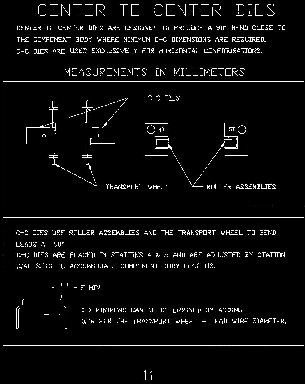
229
230
231
232
233
234
235
236
237
238
239
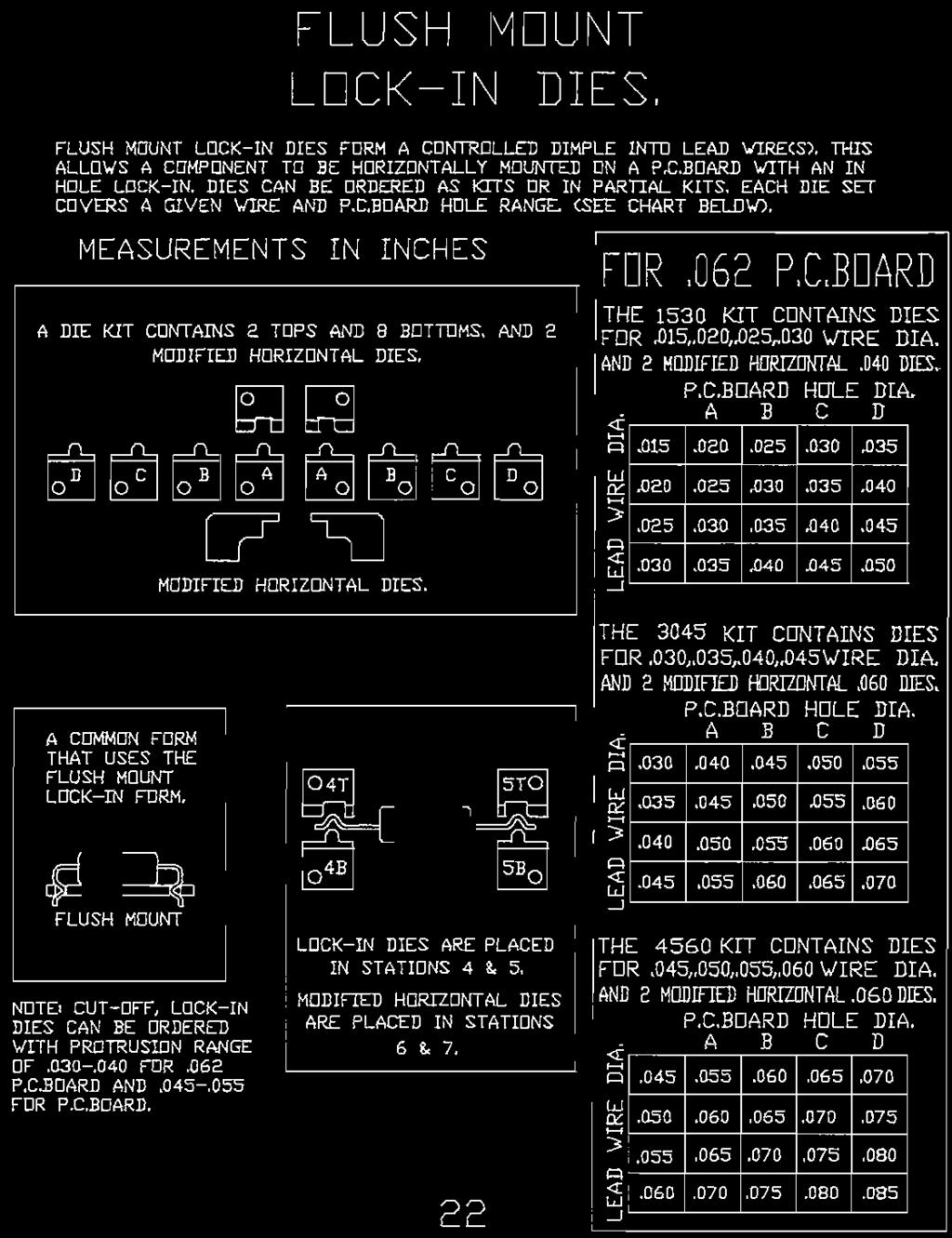
240
241
242
243
244
245
246
247
248
249

250
251
252


253 Installation Instructions CF-8 Notched Plate Kit P/N 800L-ONPK 1. WIRE CLAMPS 2. TRANSPORT WHEEL NOTCHED PLATE 3. Revised 07/11/05

254 WHEN ADJUSTING FROM ONE SET UP TO ANOTHER, ALWAYS CLOSE STATION #1 BEFORE MAKING OTHER ADJUSTMENTS. GPD Part No
CF-10 Radial Component Lead Forming Machine
 CF-10 Radial Component Lead Forming Machine User Guide Version 3.0 January 3, 2011 Prepared by GPD Global Documentation Department Copyright 1994, 1996, 2005, 2008, 2010, 2011 GPD Global All Rights Reserved
Tooling Assistance Center
 Safeguards are designed into this application equipment to protect operators and maintenance personnel from most hazards during equipment operation. However, certain safety precautions must be taken by
CF-10 Option Operating Instructions
 CF-10 Option Operating Instructions for High-Low Track Sensors with Vibratory Bowl Single Feed Selection Version 1.2 May 27, 2009 Prepared by GPD Global Documentation Department Copyright (C) 2009 GPD
RolsplicerTM. Maintenance Manual And Illustrated Parts List
 RolsplicerTM Maintenance Manual And Illustrated Parts List List of Illustrations Figure Page. Rolsplicer 3 2. Roller Adjustment 4 3. Rolsplicer 6 4. Lid Hold Down Assembly 8 5. Automatic Lid Speed Adjustment
RENA AF371Feeder Operating Manual. Feeder. Operating Manual. Manual Part #: M AF371 Operations Rev
 Manual Part #: M-3022 Feeder AF371 Operations Rev. 3-16-04 1 RENA AF371 Feeder YOUR RENA AF371 IS DISTRIBUTED BY RENA SYSTEMS INC. SERVICE AND SUPPORT FOR THIS PRODUCT IS PROVIDED BY YOUR RENA DEALER.
Model 1100B CHG Terminator. Installation Instructions
 Model 1100B CHG Terminator Installation Instructions 1 Contents: 1.0 Safety Information... 3 2.0 Set-up and Adjustments... 3 3.0 Ram Adjustments... 10 4.0 Wire Termination Quality... 12 5.0 General Maintenance...
INSTALLATION AND OPERATING INSTRUCTIONS
 ASTRO ENVELOPE FEEDER AMC-2000-5 FOR RYOBI 3302 / ITEK 3985 (2 COLOR) INSTALLATION AND OPERATING INSTRUCTIONS INTRODUCTION Thank you for purchasing the Astro Envelope Feeder. It is fast, efficient, reliable,
Heavy Duty Miniature Quick-Change Applicator (Side-Feed Type) with Mechanical or Air Feed Systems
 with Mechanical or Air Feed Systems") Heavy Duty Miniature Quick-Change Applicator (Side-Feed Type) with Mechanical or Air Feed Systems Instruction Sheet 408-8040 30 NOV 17 Rev H Ram Assembly Ram Post Locking Screw Stock Drag Drag Release
Heavy Duty Miniature Quick-Change Applicator (Side-Feed Type) with Mechanical or Air Feed Systems Instruction Sheet 408-8040 30 NOV 17 Rev H Ram Assembly Ram Post Locking Screw Stock Drag Drag Release
Adjustable Angled Incline Conveyor Owners Manual with Operating Instructions
 Adjustable Angled Incline Conveyor Owners Manual with Operating Instructions Revision 012211 Table of Contents Basic Conveyor Features 3 Getting Started 4 Setting Up the Incline Conveyor 5 Belt Removal
SUPER 30 AUTO EJECT -AE
 INSTRUCTION MANUAL SUPER 30 AUTO EJECT -AE AUTOMATIC AIR-ELECTRIC SHORELINE DISCONNECT MODEL #: 091-169-30-120 30 Amps Max, 120 Volt Max, 175 PSI Max File: IM_091-169-30-120_reva.indd Rev: B Revised By:
OEM TM-50 Quick Start Guide
 This quick start guide provides basic setup and operating instructions for the OEM TM-50. The intended use of the OEM TM-50 Taping Machine is to produce taped reels of individually sealed and consistently
HS583 Sprocket Models- Curtain/Vent Machine
 HS583 Sprocket Models- Curtain/Vent Machine Installation Manual General Installation Notes: Make sure that power is disconnected from system prior to servicing. Installation of this equipment and related
The Da-Lite Difference.
 The Da-Lite Difference. Instruction Book for Boardroom Electrol DA-LITE SCREEN COMPANY, INC. 3100 North Detroit Street Post Office Box 137 Warsaw, Indiana 46581-0137 Phone: 574-267-8101 800-622-3737 Fax:
Sno Konette. Instruction Manual Deluxe Model #1002EX Standard Model #1003EX DC Battery Model #1009EX. Cincinnati, OH USA.
 Sno Konette Instruction Manual Deluxe Model #1002EX Standard Model #1003EX DC Battery Model #1009EX Part No. 22045EX Revised June 1996 Model #1002EX Model #1003EX Cincinnati, OH 45241-4807 USA SAFETY PRECAUTIONS
JUL 17 Rev M
 Hand Crimping Tool and Cable Preparation Kit; PN 59981-1 Instruction Sheet 408-6788 24 JUL 17 Rev M PROPER USE GUIDELINES Cumulative Trauma Disorders can result from the prolonged use of manually powered
Instruction Sheet SRSR SERIES. Rotating Sliding Rail System
 Instruction Sheet SRSR SERIES Rotating Sliding Rail System THANK YOU Thank you for purchasing the SRSR Series Rotating Sliding Rail System. Please read these instructions thoroughly before assembling this
CRD610 Automatic Fitting Inserter
 CRD610 Automatic Fitting Inserter OPERATIONS MANUAL VERSION 1.2 LAST EDITED 12.12.2018 cleanroomdevices.com 1 Table of Contents Title Page. 1 Table of Contents...2 1.0 General Product & Safety Information....3
TOTALIZER-TRANSMITTER
 TOTALIZER-TRANSMITTER MODEL TR04-2 OPERATION AND MAINTENANCE MANUAL PARTS LIST FEATURING: *SEALED HOUSING *STANDARD TOTALIZER ASSEMBLY *MAGNETICALLY ACTUATED REED SWITCH 3255 WEST STETSON AVENUE HEMET,
Operator's Manual. Storage System. Ultrasound Probe Cabinet. Manufactured by:
 Storage System Ultrasound Probe Cabinet Operator's Manual Manufactured by: CIVCO Medical Solutions 102 First Street South Kalona, IA 52247 USA 319.248.6757 / 800.445.6741 WWW.CIVCO.COM Copyright 2018 All
BC Brake Caliper. (i) MEX (55) QRO (442) MTY (81) DIST. AUTORIZADO
 MEX (55) QRO (442) MTY (81) DIST. AUTORIZADO") MEX (55) 5 6 QRO (44) 95 7 60 MTY () 54 0 BC Brake Caliper (i) FORM NO. L-0066-B-040 In accordance with Nexen s established policy of constant product improvement, the specifications contained in this
MEX (55) 5 6 QRO (44) 95 7 60 MTY () 54 0 BC Brake Caliper (i) FORM NO. L-0066-B-040 In accordance with Nexen s established policy of constant product improvement, the specifications contained in this
INSTALLATION AND OPERATING INSTRUCTIONS
 ASTRO ENVELOPE FEEDER AMC-2000 INSTALLATION AND OPERATING INSTRUCTIONS INTRODUCTION Thank you for purchasing the Astro Envelope Feeder. It is fast, efficient, reliable, and designed to provide many years
6.0 SPECIFICATIONS CONTENTS. Calibration. According to factory procedureeeeeeeeeeeeeee Accuracy*
 6.0 SPECIFICATIONS Calibration According to factory procedureeeeeeeeeeeeeee Accuracy* ± 1% full scale (FS) or ± 1 graduation on scale Scale diameter 41 mm Temperature range 45 to 115 F (10-45 C) Air humidity
I N S TA L L AT I O N
 I N S TA L L AT I O N 5008 fits: H-D: '80-Up Electra glide, tour glide, road king, road glide or street glide PartS Included 1 Right Fork Mount Assembly 1 Left Fork Mount Assembly 2 H3 Driving Light Assemblies
Di-Acro 12 & 24 Slip Rollers
 OPERATOR S MANUAL & INSTRUCTIONS Di-Acro & Slip Rollers Di-Acro, Incorporated PO Box 9 Canton, Ohio Progress Street N.E. Canton, Ohio --9 -- (fax) Revised / Sale or distribution of manuals is strictly
INSTALLATION AND OPERATING INSTRUCTIONS
 ASTRO ENVELOPE FEEDER AMC-2000 INSTALLATION AND OPERATING INSTRUCTIONS INTRODUCTION Thank you for purchasing the Astro Envelope Feeder. It is fast, efficient, reliable, and is designed to give you many
Techcon Systems TS6500 CIM Automatic Techkit Mixer
 Techcon Systems TS6500 CIM Automatic Techkit Mixer User Guide English Copyright OK International 7000-2860_F 1 CONTENTS Page Number 1. Safety..3 2. Unpacking and Inspection.3 3. Description 4 4. Symbol
User s Manual and Operating Instructions
 User s Manual and Operating Instructions Model Numbers: CL-36-BDF-A, CL-42-BDF-A, CL-48-BDF-A E355088 READ AND SAVE THESE INSTRUCTIONS IMPORTANT: Read and understand all of the instructions in this manual
SKILL ATTACK PITCHING MACHINE PATENTS APPLIED FOR INSTRUCTION MANUAL. Includes: OPERATION SETUP USE & CARE SERVICE
 VOLLEYBALL SKILL ATTACK PITCHING MACHINE PATENTS APPLIED FOR INSTRUCTION MANUAL Includes: OPERATION SETUP USE & CARE SERVICE REV083115 Sports Attack, LLC. 800-717-4251 sportsattack.com WARRANTY STATEMENT
PATRIOT LIFT CO. ON-Lift Installation Guidelines
 PATRIOT LIFT CO. ON-Lift Installation Guidelines Choosing A Landing Gear Type It is important to note that the Patriot Lift Systems operates more efficiently for speed /timing with some landing gear types
Mustang Billet Aluminum Pedal Cover Kit P/N R (Manual) and R (Automatic) Installation Instructions
 and R (Automatic) Installation Instructions") 2005-06 Mustang Billet Aluminum Pedal Cover Kit P/N R08050020 (Manual) and R08050021 (Automatic) Installation Instructions 1305-R08050026-AA Page 1 of 7 1-800-59-ROUSH Before installing this Roush Performance
2005-06 Mustang Billet Aluminum Pedal Cover Kit P/N R08050020 (Manual) and R08050021 (Automatic) Installation Instructions 1305-R08050026-AA Page 1 of 7 1-800-59-ROUSH Before installing this Roush Performance
Operating Instructions and Parts Manual AHR-50 Auto Rewind Hose Reel
 Operating Instructions and Parts Manual AHR-50 Auto Rewind Hose Reel JET 427 New Sanford Road LaVergne, Tennessee 37086 Part No. M-426238 Ph.: 800-274-6848 Revision C 04/2017 www.jettools.com Copyright
Tooling Assistance Center
 Safeguards are designed into this application equipment to protect operators and maintenance personnel from most hazards during equipment operation. However, certain safety precautions must be taken by
Linear Actuator. Installation Manual. warranty installation parts list. Linear Actuator Installation Manual Page 1
 Linear Actuator Installation Manual warranty installation parts list January 2004 Linear Actuator Installation Manual Page 1 MA1221B12 Warranty Information Chore-Time Equipment ( Chore-Time ) warrants
Ocean Side-Feed Applicators
 Ocean Side-Feed Applicators Instruction Sheet 408-10389 15 AUG 17 Rev R Mechanical Feed Applicator Indicator Notch/Cut Out Ram Assembly Applicator Housing Side-Feed Strip-Form Terminals (Ref) Stock Drag
SUS9 Swing Away Series
 Positioning & Support USER MANUAL SUS9 Swing Away Series Stealth s User Manual and Maintenance Guide for the SUS9 Swing Away Series Customer Satisfaction 1.0 Stealth Products strives for 100% customer
LOR Series Trig-O-Matic Lite Overload Release Clutch
 LOR Series Trig-O-Matic Lite Overload Release Clutch P-3029-BG LOR Series Installation and Operation An Altra Industrial Motion Company Contents I. Introduction A. Operating Principle... 3 B. Torque Adjustment...
Installation Instructions
 Equipment Required: Fastener Kit: F Wrenches: 3/4, 15/16, 13mm Drill Bits: 1/4, some older models a 1/2 Other Tools: Drill, Saber Saw 5/8 Fasteners From Hitch Fastener Kit Installation Instructions GOOSENECK
INSTALLATION. Note: Not all parts will be used in the installation of this product. -cont.-
 5005 Fits: 06-up FLHX, 04-up Screamin Eagle Ultra Classic Electra Glide & Screamin Eagle Electra Glide Classic, '97-up FLHT, FLHTC, FLHTCU, FLHR PartS Included 1 Right Driving Light Assembly 1 Left Driving
Installation Instructions
 Equipment Required: Installation Instructions Fastener Kit: F Wrenches: 15/16, 10 mm Drill Bits: 1/4 Other Tools: Drill, Reciprocating Saw 9464/9474 HIDE-A-GOOSE HITCH All Fasteners Typical, Both Sides
AGRI-COVERTM SWITCH CONTROL INSTRUCTIONS
 AGRI-COVERTM SWITCH CONTROL INSTRUCTIONS Use these instructions in place of the rocker switch and solenoid sections in your roll tarp or ROLTECTM Electric Hopper Conversion instructions. Some installs
Read this entire manual before operation begins.
 Read this entire manual before operation begins. Record below the following information which is located on the serial number data plate. Serial No. Model No. Date of Installation Contents Specifications.............
203 TRANSFER CASE CONVERSION
 203 TRANSFER CASE CONVERSION PN:501 OUR FOUR TRANSFER CASE WEDGES REPLACE THE SPIDER GEARS AND CONNECT THE PLANETARY GEAR AND REAR OUTPUT SHAFT MAKING ONE UNIT. SIMILAR IN DESIGN & FUNCTION TO THE BEST
UNIVERSAL CUSTOMIZABLE MUD FLAP INSTALLATION INSTRUCTIONS
 UNIVERSAL CUSTOMIZABLE MUD FLAP INSTALLATION INSTRUCTIONS Thank you for purchasing ROCKSTARTM Splash Guard Mud Flaps. Agri-Cover, Inc. proudly manufactured these mud flaps using superior quality materials
Henny Penny Hand Breader/Sifter Model HB-11
 Henny Penny Hand Breader/Sifter Model HB-11 TECHNICAL MANUAL TABLE OF CONTENTS Section Page Section 1. MAINTENANCE... 1-1 1-1. Introduction....1-1 1-2. Safety... 1-1 1-3. Replacement of Belt...1-2 1-4.
Installation Instructions
 Equipment Required: Fastener Kit: F Wrenches: 3/4, 15/16, 13mm Drill Bits: 1/4, some older models a 1/2 Other Tools: Drill, Saber Saw 5/8 Fasteners From Hitch Fastener Kit Installation Instructions GOOSENECK
Read this entire manual before operation begins.
 Read this entire manual before operation begins. Record below the following information which is located on the serial number data plate. Serial No. Model No. Date of Installation Contents Specifications.............
Installation Instructions
 Equipment Required: Fastener Kit: F Wrenches: 3/4, 15/16, 10mm, 18mm Drill Bits: 1/4 Other Tools: Drill, Reciprocating saw 9465/9475 HIDE-A-GOOSE HITCH INSTALLATION All Fasteners Typical, Both Sides WARNING:
Backs and Support OWNER MANUAL. J&L Hardware. TFB Hardware J&L Owner s Manual
 Backs and Support OWNER MANUAL J&L Hardware TFB Hardware J&L Owner s Manual Customer Satisfaction 1.0 Stealth Products strives for 100% customer satisfaction. Your complete satisfaction is important. Please
2013+ Focus ST Focus ROUSH Exhaust Kit
 2013+ Focus ST 2011 + Focus ROUSH Exhaust Kit P/N: 421610 (1213-5E292) Application: 2013+ Ford Focus ST 2011 + Ford Focus Installation Manual Before installing your ROUSH Performance Product(s), read through
IMPORTANT RECEIVING INSTRUCTIONS:
 Gardner Bender Instruction Sheet B2000 Cyclone Bender Serial Numbers Begining With E IMPORTANT RECEIVING INSTRUCTIONS: Visually inspect all components for shipping damage. If any shipping damage is found,
( Versions Available)
") STYLE 494 ELECTRIC LADDER PIPE INSTALLATION, OPERATING AND MAINTENANCE INSTRUCTIONS ( Versions Available) The following is intended to provide the basic instructions for installation, operating and maintenance
STYLE 494 ELECTRIC LADDER PIPE INSTALLATION, OPERATING AND MAINTENANCE INSTRUCTIONS ( Versions Available) The following is intended to provide the basic instructions for installation, operating and maintenance
FD Conveyor for FD 260 Tabber
 FD 260-20 Conveyor for FD 260 Tabber Operator Manual 1/2011 First Edition TABLE OF CONTENTS 1. INTRODUCTION... 1 1.1 FD 260-20 DESCRIPTION... 1 1.2 ITEMS INCLUDED... 1 1.3 OPERATING MANUAL SAFETY TERMS...
TABLE OF CONTENTS. Important Safety Information 3. Parts List 4
 1 TABLE OF CONTENTS Important Safety Information 3 Parts List 4 Assembling THERACK 5 7 How To Unfold THERACK 8 How To Fold THERACK 9 THERACK Levels 10 Warranty 11 2 IMPORTANT SAFETY INFORMATION IMPORTANT:
OLYMPIAN MODEL 740 Operation and Service Manual
 OLYMPIAN MODEL 740 Operation and Service Manual P/N 133911-102 FCI MANUAL P/N 133865-001 Data herein has been verified and validated and believed adequate for the intended use. If the machine or procedures
Positive Stop Control. Prod. No.: , Part No.: Dimensions: 12 1/4" wide x 6 1/4"deep x 17 3/4" high Weight: 57 lbs.
 Positive Stop Control Prod. No.: 780-0050, Part No.: 77 Dimensions: 12 1/" wide x 6 1/"deep x 17 3/" high Weight: 57 lbs. (with stand) Pump Specifications All pumps maximum rated working pressure: 10,000
RAM 1500, 2019 CLASSIC & 2010-ON 2500/3500 INSTALLATION INSTRUCTIONS
 2009-18 RAM 1500, 2019 CLASSIC & 2010-ON 2500/3500 INSTALLATION INSTRUCTIONS Thank you for purchasing ROCKSTARTM Splash Guard Mud Flaps. Agri-Cover, Inc. proudly manufactured these mud flaps using superior
Installation Instructions
 Equipment Required: Fastener Kit: F Wrenches: 15/16, 10 mm Drill Bits: 1/4 Other Tools: Drill, Reciprocating Saw 9464/9474 HIDE-A-GOOSE HITCH INSTALLATION All Fasteners Typical, Both Sides WARNING: Under
Swing Arm Magnifying Lamp
 Owner s Manual & Safety Instructions Save This Manual Keep this manual for the safety warnings and precautions, assembly, operating, inspection, maintenance and cleaning procedures. Write the product s
Model 88F Twincone Magnet Wire Stripper
 110 Fairgrounds Drive P.O. Box 188 Manlius, NY 13104-0188 USA 315.682.9176 FAX: 315.682.9160 OPERATOR S MANUAL Model 88F Twincone Magnet Wire Stripper PRODUCTION WIRE PROCESSING EQUIPMENT Website: www.carpentermfg.com
Heavy Duty Miniature Quick-Change Applicator (End-Feed Type) with Mechanical or Air-Feed Systems
 with Mechanical or Air-Feed Systems") Heavy Duty Miniature Quick-Change Applicator (End-Feed Type) with Mechanical or Air-Feed Systems Instruction Sheet 408-8039 02 JUN 16 Rev G Ram Post Wire Disc Insulation Disc Insulation Crimper Stripper
Heavy Duty Miniature Quick-Change Applicator (End-Feed Type) with Mechanical or Air-Feed Systems Instruction Sheet 408-8039 02 JUN 16 Rev G Ram Post Wire Disc Insulation Disc Insulation Crimper Stripper
Quadratec Spare Tire Mounted Bike Rack
 Quadratec Spare Tire Mounted Bike Rack Installation Manual: Designed for Jeep 76-18 CJ, YJ, TJ & JK Wrangler Vehicles # 92034.1005 TO REDUCE RISK OF SERIOUS INJURY OR PROPERTY DAMAGE: READ ALL SAFETY MESSAGES
MPT-250B SPECIFICATIONS AND OPERATING INSTRUCTIONS
 1. SAFETY The MPT-250B Wire Crimp Pull Tester is a force measurement device, and as such should be operated with due caution. Operators should wear safety glasses for eye protection because the crimp under
Owner s Manual. Upper Body Unit. Serial Number Here. Date of Purchase New Hope Road, Raleigh, NC Fusion -
 Revision 3 April 2015 Upper Body Unit Owner s Manual Serial Number Here Date of Purchase www.batcafitness.com 1207 New Hope Road, Raleigh, NC - 919.255.1233 Fusion - www.batcafitness.com 4 Upper Body Station
CONTENTS. VIKING PUMP, INC. A Unit of IDEX Corporation Cedar Falls, IA USA SECTION TSM 710.1
 TECHNICAL SERVICE MANUAL industrial heavy duty motor speed pumps SERIES 4076 AND 4176 SIZES hle, ate and ale SECTION TSM 710.1 PAGE 1 of 8 ISSUE B CONTENTS Introduction....................... 1 Safety
AUTO-BREEZE Cotton Candy Machine Instruction Manual Model #3052
 Part No. 55147 Revised: August 2004 AUTO-BREEZE Cotton Candy Machine Instruction Manual Cincinnati, OH 45241-4807 USA Safety Precautions Auto-Breeze 2 INTRODUCTION Your Floss Machine warranty is described
OPERATING INSTRUCTIONS FINISHER 4300
 OPERATING INSTRUCTIONS FINISHER 4300 Model No. BA-FS43 Banner American Products, Inc. Temecula, CA Table of Contents I. For Your Safety... 2 II. Electrical Safeguards... 2-3 III. Specifications... 3 IV.
TABLE OF CONTENTS. Warranty Disclaimers Delivery Checklist After Sale Checklist Safety Set Up... 8
 TABLE OF CONTENTS Pickett Equipment Warranty... 2 Warranty Disclaimers... 3 Delivery Checklist... 4 After Sale Checklist... 4 Safety... 5-7 Set Up... 8 Machine Adjustments and Operation... 9 Maintenance
Read this entire manual before operation begins.
 Read this entire manual before operation begins. Record below the following information which is located on the serial number data plate. Serial No. Model No. Date of Installation Contents Specifications.............
Analog Durometer Model AD-100
 CHECK LINE BY ELECTROMATIC Analog Durometer Model AD-100 Operating Instructions Table of Contents 1.0 Introduction... 2 1.1 Unpacking 1.2 Complete Kit 2.0 Testing Procedure... 3 3.0 Memory Pointer... 4
User Guide IGD Series
 US User Guide IGD Series DANGER PRIOR TO USE, READ AND UNDERSTAND PRODUCT SAFETY INFORMATION. Failure to follow the instructions may result in ELECTRICAL SHOCK, EXPLOSION, or FIRE, which may result in
CSA CERTIFIED Conforms to UL 507
 Installation tion Instructions Please read and save these instructions! TURBO/MAXX12 Volt All Weather RV Ventilator Fans P/N 00-965001 Deluxe Model 1200T WITH THERMOSTAT P/N 00-965007 Standard Model 3550
Instruction Sheet. Follower Bar. Compression Roller Assembly (Roller Ass'y/Cylinder Clevis/ Roller Ass'y)
") Gardner Bender Instruction Sheet Model B400, B400D, B400L & B400DL Eegor Hydraulic Benders IMPORTANT RECEIVING INSTRUCTIONS: Visually inspect all components for shipping damage. If any shipping damage
Gardner Bender Instruction Sheet Model B400, B400D, B400L & B400DL Eegor Hydraulic Benders IMPORTANT RECEIVING INSTRUCTIONS: Visually inspect all components for shipping damage. If any shipping damage
ROUSH Billet Upper Grille Kit
 ROUSH Billet Upper Grille Kit Part Number R03010141 Application: 2010-11 Mustang GT Installation Instructions Before installing your ROUSH Performance Product(s), read through the entire installation procedure
Installation Instructions
 Equipment Required: Fastener Kit: F Wrenches: 15/16, 15/16 Crowfoot Adaptor Drill Bits: 1/4 Other Tools: Drill, Reciprocating saw Optional, Raise Bed: 18mm socket, 15 extension As an option you can loosen
Owner s Manual & Safety Instructions
 Owner s Manual & Safety Instructions Save Save This This Manual Keep Keep this this manual manual for for the the safety safety warnings warnings and and precautions, assembly, assembly, operating, inspection,
CM1000C CM1800C ChangeMakers. Operator s Manual. Seaga Manufacturing, Inc. 700 Seaga Drive Freeport, IL USA
 CM1000C CM1800C ChangeMakers Operator s Manual Seaga Manufacturing, Inc. 700 Seaga Drive Freeport, IL USA 61032 www.seagamfg.com INTRODUCTION Congratulations on the purchase of your new ChangeMaker. This
ROUSH Front Splitter Kit
 ROUSH Front Splitter Kit Kit Part Number 1310010803 Application: 2010-11 ROUSH Mustang Note: Splitter only fits onto the 2010-11 ROUSH Front Fascia. Installation Instructions Before installing your ROUSH
Installation Instructions GOOSENECK MOUNTING KIT Chevrolet/GMC 1500/2500/3500 All except 4-door Crew-Cab
 GOOSENECK MOUNTING KIT Equipment Required: Fastener Kit: F Wrenches: 3/4, 7/8, 15/16 Drill Bits: 1/4 Other Tools: Drill WARNING: Under no circumstances do we recommend exceeding the towing vehicle manufacturers
CRD600 Automatic Fitting Inserter
 CRD600 Automatic Fitting Inserter OPERATIONS MANUAL VERSION 2.3 LAST EDITED 12.07.2018 cleanroomdevices.com 1 Table of Contents Title Page.. 1 Table of Contents. 2 1.0 General Product & Safety Information...3
RT404-FLEX II ROTARY TABLE OPERATING MANUAL
 P/N 561447 REV E AUG. 03 REV D NOV. 01 REV C APR. 01 REV B JULY 98 REV A AUG. 97 AUGUST 2003 RT404-FLEX II ROTARY TABLE OPERATING MANUAL 2003 I&J FISNAR INC. RT404-FLEX II ROTARY TABLE NOTE: Unlike the
Cincinnati, OH USA
 Astro Pop Warmer Instruction Manual Model #2002 Part No. 61987 Revised July 2000 Cincinnati, OH 45241-4807 USA e-mail: goldme19@eos.net www.gmpopcorn.com SAFETY PRECAUTIONS INTRODUCTION Your new #2002
EASYBIRD OSCILLATING BASE 12VDC Part No
 EASYBIRD OSCILLATING BASE 12VDC Part No. 40913 Instruction Manual WARNING! TO AVOID SERIOUS INJURY THOROUGHLY READ INSTRUCTIONS BEFORE USING OSCILLATING BASE. i Table of Contents Section Page I. Introduction...
INSTALLATION MANUAL. Thunderstone Manufacturing LLC 3400 West O Street Lincoln, NE (Fax)
") INSTALLATION MANUAL August 7 th 2018 43 /48 /50 2011 and Older Timpte STD/Split 36 Style Hopper Trailers with Roller Bearing Doors Kit #101533 for 96w & Kit #101534 for 102w Thunderstone Manufacturing
INSTALLATION MANUAL August 7 th 2018 43 /48 /50 2011 and Older Timpte STD/Split 36 Style Hopper Trailers with Roller Bearing Doors Kit #101533 for 96w & Kit #101534 for 102w Thunderstone Manufacturing
Before installing your Roush Performance Product(s), read through the entire installation procedure and check to make sure all items are present.
, read through the entire installation procedure and check to make sure all items are present.") 2005-2006 Ford Mustang GT Legal / Stage 3 / Offroad Exhaust Kits for Roush Rear Valence Installation Instructions Application: 2005- Ford Mustang GT Model Must have Roush Rear Valence Kit #R03030061 Before
2005-2006 Ford Mustang GT Legal / Stage 3 / Offroad Exhaust Kits for Roush Rear Valence Installation Instructions Application: 2005- Ford Mustang GT Model Must have Roush Rear Valence Kit #R03030061 Before
ECLIPSE Laundry Dispenser Controller
 ECLIPSE Laundry Dispenser Controller Reference Manual Programming and Operation Online and downloadable Product Manuals and Quick Start Guides are available at www.hydrosystemsco.com Please check online
Part Number Mini Linear Lift Assembly Installation & Operator s Instruction Manual
 Part Number 39644 Mini Linear Lift Assembly Installation & Operator s Instruction Manual April 1999 MV1505C Chore-Time Warranty Mini Linear Lift Assembly Manual Chore-Time Warranty Chore-Time Equipment
MODEL 660 AUTOMATIC FASTENING CENTER OPERATOR S MANUAL
 MODEL 660 AUTOMATIC FASTENING CENTER OPERATOR S MANUAL Copyright: January 13, 2003 Revised: 080612 Serial No. 0506113. 1 TABLE OF CONTENTS INTRODUCTION..3 OPERATOR SAFETY... 3 SYSTEM REQUIREMENTS..4 INSTALLATION
Installation Instructions
 Equipment Required: Fastener Kit: F Wrenches: 3/4, 15/16 Drill Bits: 1/4 Other Tools: Drill, Reciprocating saw WARNING: Under no circumstances do we recommend exceeding the towing vehicle manufacturers
STRIKEMASTER. Ice Augers
 BIG VOLT Owner s Manual ATTENTION: PRIOR TO FIRST USE It is recommended that everyone who uses this product should read the StrikeMaster owner s manual. It is recommended to use a 1 volt, deep cycle battery
B DUAL DRUM SANDER
 OWNER S MANUAL B2022-25 DUAL DRUM SANDER INDEX GENERAL SAFETY INSTRUCTIONS Page 3 Specifications Page 4 Features Page 5 Assembly Instructions Initial Assembly Page 6 Installing Abrasives Page 7 Adjusting
instructions ZCM ZCM START International 4270 Airborn Dr. Addison, TX 75001, USA Tel Fax
 ZCM 1000 START International 4270 Airborn Dr. Addison, TX 75001, USA Tel 972.248.1999 Fax 972.248.1991 TM START Japan Corporation 1-26-14 Toshin-Cho Itabashi-ku Tokyo, Japan Tel 81.3.3554.5608 instructions
INSTALLATION INSTRUCTIONS
 INSTALLATION INSTRUCTIONS Thank you for purchasing ROXTERTM Hitch Mounted Mud Flaps. Agri-Cover, Inc. proudly manufactured these mud flaps using superior quality materials and workmanship. With proper
Operating Instructions and Parts Manual Hydraulic Pipe Bender Models: JHPB-20 (2-inch), JHPB-30 (3-inch)
, JHPB-30 (3-inch)") Operating Instructions and Parts Manual Hydraulic Pipe Bender Models: JHPB-20 (2-inch), JHPB-30 (3-inch) JET 427 New Sanford Road LaVergne, Tennessee 37086 Part No. M-331900 Ph.: 800-274-6848 Revision
Operating Instructions and Parts Manual Hydraulic Pipe Bender Models: JHPB-20 (2-inch), JHPB-30 (3-inch) JET 427 New Sanford Road LaVergne, Tennessee 37086 Part No. M-331900 Ph.: 800-274-6848 Revision
Installation Instructions
 Installation Instructions ELECTRIC CONVERSION KIT 3 ALUMINUM ROLL TUBE IMPORTANT: This Electric Conversion Kit has been designed for systems with a 3 aluminum roll tube. It is assumed that the tarping
Dear Customer, User Memo: Please visit us on facebook or twitter! Thank you for purchasing this product.
 Owner s Manual 1 Dear Customer, Thank you for purchasing this product. For optimum performance and safety, please read these instructions carefully. User Memo: Date of purchase: Dealer name: Dealer address:
Installation Instructions
 Equipment Required: Installation Instructions Fastener Kit: F Wrenches: 3/4, 15/16 Drill Bits: 1/4 Other Tools: Drill WARNING: Under no circumstances do we recommend exceeding the towing vehicle manufacturers
14", 18" & 24" Fiberglass Turbo Fans Installation & Operator s Instruction Manual
 14", 18" & 24" Fiberglass Turbo Fans Installation & Operator s Instruction Manual 09484:09#52
Upper Extremities USER MANUAL GAT444-IP. Stealth s User Manual And Maintenance Guide for the Gatlin Swivel Tablet Mount
 Upper Extremities USER MANUAL GAT444-IP Stealth s User Manual And Maintenance Guide for the Gatlin Swivel Tablet Mount Customer Satisfaction 1.0 Stealth Products strives for 100% customer satisfaction.
TRU-TIME ADJUSTABLE CAM GEAR Part Number: BK & BK
 TRU-TIME ADJUSTABLE CAM GEAR Part Number: 23-801BK & 23-802BK! WARNING: This installation is not for the mechanically challenged! If you are not mechanically inclined or do not understand the procedure
TRAILER WINCH MODELS ST315 AND ST712. General Safety (Continued) Description. Unpacking. General Safety Information.
 Description. Unpacking. General Safety Information.") OPERATION AND MAINTENANCE MANUAL TRAILER WINCH READ CAREFULLY BEFORE ATTEMPTING TO ASSEMBLE, INSTALL, OPERATE OR MAINTAIN THE PRODUCT DESCRIBED. PROTECT YOURSELF AND OTHERS BY OBSERVING ALL SAFETY INFORMATION.
OPERATION AND MAINTENANCE MANUAL TRAILER WINCH READ CAREFULLY BEFORE ATTEMPTING TO ASSEMBLE, INSTALL, OPERATE OR MAINTAIN THE PRODUCT DESCRIBED. PROTECT YOURSELF AND OTHERS BY OBSERVING ALL SAFETY INFORMATION.