INSTALLING THE DRUM MOTOR:
|
|
|
- Barbra Gibbs
- 5 years ago
- Views:
Transcription

 is immersed in oil. For special mounting arrangements, consult your Van der Graaf representative.")
.")
1 Drum Motor Installation Manual 2 Van der Graaf Court, Tel: Fax: Brampton, ON L6T 5R6 Canada Technical Support: INSTALLING THE DRUM MOTOR: The Drum Motor MUST be mounted horizontally, square to the conveyor frame and parallel to the idler pulley. The arrow on the shaft opposite the junction box MUST be pointing up, with no more than 30 degrees off of vertical. This will ensure that the high speed rotating gear (position 11) is immersed in oil. For special mounting arrangements, consult your Van der Graaf representative. NOTE: The Drum Motor has been factory filled with the correct amount and type of oil, and does not require any additional oil. Oil change recommended at 50,000 hour intervals (see page 10). ELECTRICAL CONNECTION: To ensure proper electrical connection, always reference the connection diagrams provided (see pages 5-7). Be sure to use qualified personnel and observe compliance with local electrical codes. If in doubt, consult your Van der Graaf representative. Ensure that the motor is being installed with the appropriate overload protection device(s), (fuse, breakers, thermal overload protection {GV-THERM}) if equipped. Reference the Drum Motor nameplate to determine allowable full load amperage. When the motor is equipped with a backstop (TB) device, the motor must be connected electrically according to the correct rotational direction (see page 8 for complete instructions). PRIOR TO STARTING: 1. Be sure that the Drum Motor is correctly connected and supplied with the rated voltage. 2. Check that the Drum Motor and conveyor belt are unobstructed and free to rotate. CAUTION: Never over tension the conveyor belt as internal damage may occur.
2 Sprockets with Drive Sleeve Assembly Instructions 1. Slide sprocket and drive sleeve (item 1) over the shell. 2. Align groove in shell with the pin groove in the sprocket. 3. Place drive pin (item 2) in the groove on the shell and sprocket assembly (item 1). 4. Align holes in the pin with the holes in the sprockets for the set screws (item 3 & 4). 5. Make sure set screws (item 3) are all the way through the sprocket (item 1) and the drive pin (item 2) to the shell. 6. Tighten set screws (item 3) and back it off 1/4 turn. 7. Repeat steps 1-6 for each sprocket. 8. Align sprockets to belt and space them as per the belt manufacturer recommendation. 9. Lock the center sprocket or one sprocket in place, by tightening the set crews (item 3). 10. The remainder sprockets should be floating, or as recommended by the belt manufacturer. 11. Install locking set screw (item 4) in each sprocket until they reach the drive sleeve. (NOTE: Do not over tighten the screws as you may separate the sprocket from the drive sleeve) IMPORTANT NOTE: Do not use a hammer on installation of sprockets as this will destroy the sprockets and voids the warranty.
3 Connection Diagrams SINGLE VOLTAGE - THREE PHASE DUAL VOLTAGE - THREE PHASE (STAR/DELTA) DUAL VOLTAGE - THREE PHASE (230/460 VOLTS)
 THREE PHASE WITH BRAKE")
4 SINGLE PHASE (110 VOLTS) SINGLE PHASE (220 VOLTS) THREE PHASE WITH BRAKE (RTM)

5 THREE PHASE WITH CLUTCH BRAKE (CBTM) Connecting a Drum Motor Equipped with a Backstop (TB) Device 1. Look for the brass arrow on the end flange. It will indicate which direction the drum motor will rotate. 2. Mark the three incoming power supply leads with numbers L1, L2, L3. Ensure that the ground lead is properly connected to the ground. 3. Connect the incoming power supply leads: L1 to motor lead #1 L2 to motor lead #2 L3 to motor lead #3 4. Turn the power to the motor ON and OFF, (no more than 0.5 seconds on the ON position). If the motor rotates then the connection is correct and you can proceed to step 5. If the motor does not rotate, interchange any of the two power supply leads. Example: L1 to motor lead #2 L2 to motor lead #1 Turn the power ON and the motor should rotate in the correct direction. Change the markings on the incoming power supply leads to correspond with the motor leads. Example: L2 to be changed to L1 and L1 to be changed to L2. Before Step 4 is complete, the motor should be running in the correct rotation and the connection should be as follows: Power supply Motor Leads L1 to 1 L2 to 2 L3 to 3 When that is completed, proceed to step Finalize the motor connection: Power supply Motor Leads L1 to 1 L2 to 2 L3 to 3 6. Turn ON the motor.


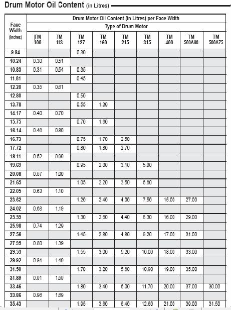
6 Releasing & Engaging a Drum Motor Equipped with a Manual Release Backstop (MRB) Device To Release the Backstop Feature: 1. Bring the drum motor to full stop and disconnect power. 2. Remove the shaft cap located on the shaft end, opposite the junction box or cable entry. 3. Using a 10mm deep socket 1/4 drive and a ratchet; insert socket into the shaft and turn clockwise until the end, approximately 15 turns and allow motor to rotate freely in opposite direction. 4. Remove socket and re-install the shaft cap. The motor will operate in both directions. To Engage the Backstop Feature - Repeat Steps 1 & 2: 3. Using a 10mm deep socket 1/4 drive and a ratchet; insert socket into the shaft and turn counter clockwise, approximately 15 turns. NOTE: Do not exert force to turn the socket as some movement for the drum may be necessary to align the shaft to engage to its mating part. Forcing the rotation of the socket may result in damage to internal components. 4. Once re-engaged, remove the socket and re-install the shaft cap. The motor will operate in only the direction indicated by the brass arrow mounted on the side of the unit. NOTE: The drum motor is shipped with the Backstop already engaged. Oil Change Instructions All Drum Motors are factory filled with oil that is free of detergent additives. It is recommended that oil changes be performed at 50,000 hour intervals. NOTE: Do not use oil additives which can cause damage to the motor insulation or seals. Electrically conductive-bases oils, such as graphite and molybdenum disulfide, should not be used, as they will result in electric motor insulation damage. OIL CHANGE 1. Allow the drum motor to cool to normal temperature. 2. Rotate the drum motor until the oil plug is located in the 6 o clock position. 3. Unscrew the oil plug and allow the oil to drain completely. (Note: There may be internal pressure released when removing the oil plug, this is normal.) 4. Refill the drum motor with the suggested oil type (see below) and amount of oil (page 11 - Drum Motor Oil Content). To verify the oil level, rotate the drum motor until the embossed arrow on the end flange (Models: TM160 - TM500), or the nameplate on the end flange (Models: TM100 - TM127) is pointed in the 12 o clock position. The oil plug will be aproximately in the 4 o clock position. The oil level should be up to the level of the oil plug.* 5. Re-install the oil plug and if available, install a new copper seal. *For Airline Specified Drum Motors, please call Van der Graaf Technical Support: 1 (888) for appropriate oil levels.

7
TM315 - TM500 DRUM MOTORS 12.5" to 20.0" diameter 1.5 to 40 hp HEAVY-DUTY
 Engineered to Keep Your Business Running TM315 - TM500 DRUM MOTORS 12.5" to 20.0" diameter 1.5 to 40 hp HEAVY-DUTY BELT PULL (BP) = (F0 + F1 + F2) Roller Bed Conveyor Slider Bed Conveyor F0 = 0.04 (2P
SSV TM100 - SSV TM215 DRUM MOTORS 4.0" to 8.5" diameter 0.11 to 7.5 hp SANITARY DRUM MOTORS
 Engineered to Keep Your Business Running SSV TM100 - SSV TM215 DRUM MOTORS 4.0" to 8.5" diameter 0.11 to 7.5 hp SANITARY DRUM MOTORS BELT PULL (BP) = (F0 + F1 + F2) Roller Bed Conveyor Slider Bed Conveyor
SELF PRIMING CHEMICAL SERVICE PUMPS
 SELF PRIMING CHEMICAL SERVICE PUMPS INSTALLATION AND OPERATING INSTRUCTIONS This Manual covers: SELF PRIMING MODEL RANGE J50ECX TO J250ECX STAINLESS STEEL*, and NON METALLIC SEAL PUMP MODEL: SERIAL NO:
Van der Graaf Power Transmission Equipment
 Van der Graaf Power Transmission Equipment Benefits What is a Drummotor? Long life span The Van der Graaf Drummotor is a one component conveyor drive which houses all components internally, eliminating
1995 Mitsubishi Montero LS. Ensure timing marks are aligned. Mark timing belt direction of rotation.
 TIMING BELT NOTE: Ensure timing marks are aligned. Mark timing belt direction of rotation. Removal 1. Disconnect negative battery cable. Drain engine coolant. Remove engine coolant reservoir tank, fan
Product information Drummotors TM 620A75. Van der Graaf Power Transmission Equipment.
 Product information Drummotors TM 620A75 Van der Graaf Power Transmission Equipment www.vandergraafpte.nl The TM 620 s playground Introduction TM 620A75 A wide range of applications Van der Graaf has
1992 Mitsubishi 3000GT VR-4
 TIMING BELT Removal (Diamante SOHC) 1. Remove left front and left side splash shields. Using engine hoist, lift engine just enough to remove weight from engine mounts. Remove drive belts. Remove A/C tensioner
Removal. All vehicles. Published: 11-Mar-2014 Engine - TDV6 2.7L Diesel - Timing Belt In-vehicle Repair. Special Tool(s) Check Pin - Camshaft Pulleys
 Check Pin - Camshaft Pulleys") Published: 11-Mar-2014 Engine - TDV6 2.7L Diesel - Timing Belt In-vehicle Repair Special Tool(s) Check Pin - Camshaft Pulleys 303-1132 Timing Pin - Camshaft Pulleys 303-1126 Timing Pin - Automatic Transmission
Published: 11-Mar-2014 Engine - TDV6 2.7L Diesel - Timing Belt In-vehicle Repair Special Tool(s) Check Pin - Camshaft Pulleys 303-1132 Timing Pin - Camshaft Pulleys 303-1126 Timing Pin - Automatic Transmission
Engine Dismantle and Assemble ( )
") Engine Dismantle and Assemble (2 34 8) Special Tools 2-036A Remover for pilot bearing 2-37 Oil seal installer/aligner 237 2036A 2-044A Installer/Aligner, Pilot Bearing/Clutch Plate 244 2-44 Inlet manifold
Engine Dismantle and Assemble (2 34 8) Special Tools 2-036A Remover for pilot bearing 2-37 Oil seal installer/aligner 237 2036A 2-044A Installer/Aligner, Pilot Bearing/Clutch Plate 244 2-44 Inlet manifold
Product information Drummotors TM 215B50. Van der Graaf Power Transmission Equipment.
 Product information Drummotors TM 215B50 Van der Graaf Power Transmission Equipment www.vandergraafpte.nl The TM 215B50 s playground Introduction TM 215B50 A wide range of applications Van der Graaf has
MEMORY SEAL BALL VALVES MAINTENANCE MANUAL 2 12, Class 150 & 300, Regular Port, Flanged Unibody
 MEMORY SEAL BALL VALVES MAINTENANCE MANUAL 2 12, Class 150 & 300, Regular Port, Flanged Unibody I INTRODUCTION These rugged, versatile, high performance, regular port, ball valves meet all requirements
The EFL 2000/1 & 2 User Guide Test Sieve Shaker. Contents
 The EFL 2000/1 & 2 User Guide Test Sieve Shaker ISSUE 04-02 Contents Description Page 1 Setting Up: 2-8 Unpacking 2 Assembly 3 Clamping Assembly 4 Electrical Connections 5 Sieve Stacking 6 8 Operating
COOKSON OWNER'S MANUAL
 COOKSON OWNER'S MANUAL FDO-A10 INDUSTRIAL DUTY FIRE DOOR OPERATOR R L I S T E D 3040233 US CONTROL PANEL SERIAL# OPERATOR SERIAL# 9001.DWG ECN 0959 REV 4 SPECIFICATIONS MOTOR TYPE:...INTERMITTENT HORSEPOWER:...1/8
MP and MP Diaphragm and Seal Kits for MP8000 Series Actuators
 MP8000-6325 and MP8000-6350 Diaphragm and Seal Kits for MP8000 Series Actuators Contents of the MP8000-6325 Diaphragm and Seal Kit for MP82 and MP83 Actuators One seal, 5/8 in. Internal Diameter (I.D.)
MGA Twin Cam Engine Assembly.
 MGA Twin Cam Engine Assembly. The following article is a collection of notes of things to be observed in the assembling of MGA Twin Cam engines. To be read in conjunction with the Workshop Manual. It does
Hyponic. Quick-Start Guide. Manual
 Hyponic Quick-Start Guide 1 Manual 12.002.61.008 Hyponic Safety Consult the factory if Hyponic products are driven by DC motors, variable frequency AC drives, or speeds other than standard catalog input
Product information Drummotors TM Van der Graaf Power Transmission Equipment.
 Product information Drummotors TM 315-40 Van der Graaf Power Transmission Equipment www.vandergraafpte.nl Benefits TM 315-40 A wide range of applications Van der Graaf has achieved a prominent position
Product information Drummotors TM Van der Graaf Power Transmission Equipment.
 Product information Drummotors TM 400-60 Van der Graaf Power Transmission Equipment www.vandergraafpte.nl The TM 400 s playground Introduction TM 400-60 A wide range of applications Van der Graaf has
Product information Drummotors TM 100B25. Van der Graaf Power Transmission Equipment.
 Product information Drummotors TM 100B25 Van der Graaf Power Transmission Equipment www.vandergraafpte.nl The TM 100 s playground Introduction TM 100B25 A wide range of applications Van der Graaf has achieved
Kysor On/Off Rear Air Fan Drive
 . Proper precautions must be taken to prevent personal injury from contact with moving parts, unintended engine start, or other hazards present when working with powered equipment. Refer to the vehicle
Product information Drummotors TM Van der Graaf Power Transmission Equipment.
 Product information Drummotors TM 315-50 Van der Graaf Power Transmission Equipment www.vandergraafpte.nl The TM 315 s playground Introduction TM 315-50 A wide range of applications Van der Graaf has achieved
Disassembling and assembling transmission
 27-640 Disassembling and assembling transmission Preceding work: Removing and installing transmission with torque converter (27-600). Operation number of operation texts and operation values or standard
TRANSMISSION 6.7 GENERAL HOME. See Figure The transmission is a five-speed constantmesh type housed in an extension of the crankcase.
 TRANSMISSION 6.7 GENERAL See Figure 6-45. The transmission is a five-speed constantmesh type housed in an extension of the crankcase. Mainshaft Neutral Mainshaft st Gear b06x6x Countershaft 4 Out 5 Countershaft
GM 6-Cylinder Cam Tool Set 3.0L and 3.2L Operating Instructions
 GM 6-Cylinder Cam Tool Set 3.0L and 3.2L Operating Instructions Set Includes: Locking Tool... 536594 Locking Tool... 536595 Crankshaft Holding Tool... 536596 Alignment Gauge... 536608 Belt Installation
DYNAFLUID 2000 STEAM & WATER MIXING VALVE INSTALLATION & OPERATING MANUAL
 DYNAFLUID 2000 STEAM & WATER MIXING VALVE INSTALLATION & OPERATING MANUAL LILLY ENGINEERING COMPANY 217 CATALPA STREET P.O. BOX 173 ITASCA, ILLINOIS 60143 630-773-2222 FAX: 630-773-3443 www.lillyengineering.com
Submersible Tank Pump
 Submersible Tank Pump Applications: Silent household pressure systems, garden irrigation, or water transfer. Performance Outline Pump Features High efficiency moulded impellers Stainless steel construction,
ESE Series Cast Iron Sewage Pumps
 Owner s Manual ESE Series Cast Iron Sewage Pumps TABLE OF CONTENTS General Safety.................... 2 Specifications..................... 3 Installation.................... 4 & 5 Troubleshooting...................
1. Disconnect negative battery cable. 2. Remove upper and lower front timing belt covers..
 BELT AND SPROCKETS-TIMING REMOVAL TIMING BELT Zoom 1. Disconnect negative battery cable. 2. Remove upper and lower front timing belt covers.. CAUTION: When aligning crankshaft and camshaft timing marks
3 Phase Smart Controller
 3 Phase Smart Controller Installation and Owner s Manual STP-SCIII 208-230 VAC, 60Hz, 120 Volt Coil Franklin Fueling 3760 Marsh Rd. Madison WI 53718 USA Tel: +1 608 838 8786 800 225 9787 Fax: +1 608 838
OEM TM-50 Quick Start Guide
 This quick start guide provides basic setup and operating instructions for the OEM TM-50. The intended use of the OEM TM-50 Taping Machine is to produce taped reels of individually sealed and consistently
Discount-Equipment.com
 REQUIRED TOOLS LS Series Remix Shaft Installation Instructions /8", /6", /2" Allen Wrenches Snap Ring Pliers (Light Duty) /" Combination Wrench Loctite #22 Blue /" Socket w/ /8" Ratchet Electric Drill
Discount-Equipment.com
 LS40D, LS40TD, LS50TD, LS60TD LS-Series Remix Shaft Coupler Retrofit Kit Installation Instructions The following instructions are intended to assist the user in the installtion of the LS-Series Remix Shaft
MODCO TM FIGURE 500 CLOSURE
 CLOSURE SPECIALISTS SINCE 1981 MODCO TM FIGURE 500 CLOSURE INSTALLATION INSTRUCTIONS (!) THE INFORMATION PROVIDED IN THIS DOCUMENT IS VERY IMPORTANT (!) & (!) needs to be shared with everyone involved
OPEN/CLOSE SERVICE ELECTRIC ACTUATORS OPERATION AND MAINTENANCE MANUAL COMMERCIAL AND INDUSTRIAL VALVES AND AUTOMATION
 SERIES 1000-X OPEN/CLOSE SERVICE ELECTRIC ACTUATORS OPERATION AND MAINTENANCE MANUAL COMMERCIAL AND INDUSTRIAL VALVES AND AUTOMATION Publication S1000X-110 VER0215-1 For information on this product and
REMOVAL AND REPLACEMENT
 2002 Mitsubishi Truck Montero LTD 4WD V6-3.5L SOHC Vehicle > Engine, Cooling and Exhaust > Engine > Timing Components > Timing Belt > Service and Repair REMOVAL AND REPLACEMENT https://my.alldata.com/repair/#/repair/article/36847/component/64/itype/401/nonstandard/
Engine Dismantle and Assemble ( )
") Engine Dismantle and Assemble ( 34 8) Special Tools 5 053 Slide hammer 47 Vibration damper remover 47 5053 00 Splined head socket, cylinder head bolts 87 Mounting stand with geared drive 00 059C Installer
Engine Dismantle and Assemble ( 34 8) Special Tools 5 053 Slide hammer 47 Vibration damper remover 47 5053 00 Splined head socket, cylinder head bolts 87 Mounting stand with geared drive 00 059C Installer
REMOVAL & INSTALLATION
 REMOVAL & INSTALLATION CAUTION: This application is an interference engine. Do not rotate camshaft or crankshaft when timing belt is removed, or engine damage may occur. TIMING BELT Removal 1. Raise and
Timing Belt: Service and Repair Timing Belt Replacement
 2003 Saturn Truck VUE V6-3.0L VIN B Copyright 2007, ALLDATA 9.50 Page 1 Timing Belt: Service and Repair Timing Belt Replacement Removal Procedure 1. Remove the front timing belt cover. 2. Rotate the crankshaft
3.0 CHARACTERISTICS E Type CO-4 Step-Time Overcurrent Relay
 41-106E Type CO-4 Step-Time Overcurrent Relay A core screw accessible from the top of the switch provides the adjustable pickup range. The IIT contacts are connected in the trip circuit to trip instantaneously.
Installation and Maintenance Manual
 Installation and Maintenance Manual WorldWide Electric Corporation WSMR Series Backstop Assemblies *Suitable for use in WWE Ultimate series Shaft Mount Reducers only. WorldWide Electric Corporation Phone:
Volkswagen New Beetle 2.0 Liter 4-cyl General, Engine (Engine Code AEG) 13 Engine-Crankshaft, Cylinder block (Page GR-13)
 13 Engine-Crankshaft, Cylinder block (Page GR-13)") 13 Engine-Crankshaft, Cylinder block (Page GR-13) Engine, disassembly and assembly 10-222 A/21 guide from 10-222 A support tool, modifying Ribbed belt, removing and installing Semi-automatic toothed belt
13 Engine-Crankshaft, Cylinder block (Page GR-13) Engine, disassembly and assembly 10-222 A/21 guide from 10-222 A support tool, modifying Ribbed belt, removing and installing Semi-automatic toothed belt
CAM CLUTCHES BREU SERIES
 CAM CLUTCHES BREU SERIES TSUBAKI EMERSON - the working principle of lift-off Cam Clutches - 2 Cams of BREU series Cam Clutches are designed to lift off, having no more contact with inner- and outer race
IMPORTANT WARRANTY & INSTALLATION INSTRUCTIONS ATTACHED
 IMPORTANT WARRANTY & INSTALLATION INSTRUCTIONS ATTACHED Please Forward All Attached Information to Consumer Warranty Not Valid Unless Returned to CORSA Performance STOP Please take time to read and understand
Models Affected: Certain 2013 Model Year Propane Vision Buses Equipped with Ford 6.8L Engines CORRECTIVE ACTION ---- PROCEDURE
 Models Affected: Certain 2013 Model Year Propane Vision Buses Equipped with Ford 6.8L Engines ISSUE Certain 2013 model year propane Vision buses equipped with Ford 6.8L engines may not have the service
Matala. VersiFlow Series. Instruction and Maintenance Manual
 VersiFlow Series High Flow Multi-Purpose "Versatile " Pump V-3200 1/5HP 150W / Discharge 2 V-3900 1/3HP 250W / Discharge 2 V-4700 1/2HP 400W / Discharge 2 V-5600 1HP 750W / Discharge 2 Instruction and
TRANSMISSION 6.7 GENERAL HOME. See Figure The transmission is a five-speed constantmesh type housed in an extension of the crankcase.
 TRANSMISSION 6.7 GENERAL See Figure 6-46. The transmission is a five-speed constantmesh type housed in an extension of the crankcase. b06x6x Neutral st Gear Mainshaft Mainshaft 4 5 4 5 Countershaft Out
Mandatory X Information Recommended Change. Series/Parts Affected: LS40D, LS40TD, LS50TD and LS60TD Concrete Pumps
 Service Bulletin No. CP20060428 Subject: Remix Shaft Coupler Retrofit Kit Model: LS40D, LS40TD, LS50TD & LS60TD Product Group: Concrete Pump Date: April 28, 2006 SERVICE BULLETIN Group: CP Mandatory X
20.Cylinder Block. Cylinder Block A: REMOVAL ME(H4DOTC)-63 ST CRANKSHAFT STOPPER
-63 ST CRANKSHAFT STOPPER") Cylinder Block MECHANICAL 20.Cylinder Block A: REMOVAL Before conducting this procedure, drain engine oil completely. 1) Remove the intake manifold. 2)
Cylinder Block MECHANICAL 20.Cylinder Block A: REMOVAL Before conducting this procedure, drain engine oil completely. 1) Remove the intake manifold. 2)
Timing Belt: Service and Repair Installation NOTE: Check the water pump for water leakage and the oil seal for oil leakage.
 1991 Daihatsu Truck Rocky L4-1589cc 1.6L SOHC Page 1 Timing Belt: Service and Repair Installation NOTE: Check the water pump for water leakage and the oil seal for oil leakage. Repair any water leakage
BALDOR MN413 Brakes Manual
 BALDOR MN413 Brakes Manual http://www.manuallib.com/baldor/mn413-brakes-manual.html The DODGE D-Series motor brakes are manufactured to NEMA standards for mounting to C-face and double shafted motors.
Section 5: Parts Replacement
 Section 5: Parts Replacement Should the STAR TRAC 4500 Treadmill experience a problem requiring replacement of a specific part, the following procedures will help and instruct in the replacement of major
LS Series. Remix Shaft Installation Instructions REQUIRED TOOLS PARTS WORK SAFELY! PREPARATION/SAFETY PROCEDURES
 REQUIRED TOOLS LS Series Remix Shaft Installation Instructions /8", /6", /2" Allen Wrenches Snap Ring Pliers (Light Duty) /" Combination Wrench Loctite #22 Blue /" Socket w/ /8" Ratchet Electric Drill
2003 Saturn Vue. SATURN 3.0L V6 DOHC - L-Series After VIN & Vue
 TIMING BELT Removal 1. Disconnect negative battery cable. Remove air cleaner assembly. 2. Raise and support vehicle. Remove right front wheel. Remove lower front splash shield. 3. Lower vehicle. Loosen,
TM-1620 OPERATING INSTRUCTIONS AND OWNERS MANUAL
 TM-1620 OPERATING INSTRUCTIONS AND OWNERS MANUAL tracopackaging.com 800-284-WRAP 620 SOUTH 1325 WEST OREM, UT. PHONE 800-284-WRAP (9727) IMPORTANT: READ ALL INSTRUCTIONS BEFORE OPERATING EQUIPMENT Your
Kysor Rear Air Fan Drives
 On/Off Technology for Heavy-Duty Truck Applications Installation & Service Guide Kysor Rear Air Fan Drives thermal.borgwarner.com For Additional BorgWarner Thermal Systems Information: 800-927-7811 USA
TIMING BELT/CHAIN AND SPROCKETS
 9-82 ENGINE 4.7L DN TIMING BELT / CHAIN COVER(S) (Continued) Fig. 130 Accessory Drive Belt Tensioner 1 - TENSIONER ASSEMBLY 2 - FASTENER TENSIONER TO FRONT COVER Fig. 132 Timing Chain Cover Fasteners (4)
Service Handbook HD /97
 Service Handbook HD 1050 5.905-032 07/97 Foreword HD 1050 Foreword Indispensable prerequisites for the competent execution of service procedures are comprehensive, real-life training workshops for technical
Technical Precautions for Design, Installation and Maintenance
 The precautions below will enable conveyor engineers, system integrators, and end users to properly design, install, operate, and maintain conveyor systems using Rulmeca Motorized Pulleys. Ignoring any
Tech Note Truck 14 & 15.5 Twin Plate Cast Iron Type Installation Guidelines
 1. (14 & 15.5 ) Check condition of the flywheel. Grind to resurface or replace flywheel. Surface MUST BE machined or premature clutch failure can occur. Flywheel depth must be 2.938 (74.62mm) for 14 (350mm)
CONTENTS. VIKING PUMP, INC. A Unit of IDEX Corporation Cedar Falls, IA USA SECTION TSM 710.1
 TECHNICAL SERVICE MANUAL industrial heavy duty motor speed pumps SERIES 4076 AND 4176 SIZES hle, ate and ale SECTION TSM 710.1 PAGE 1 of 8 ISSUE B CONTENTS Introduction....................... 1 Safety
Timing Belt Replacement
 Timing Belt Replacement Tools Required Timing Belt Alignment Kit Crank Hub TORX Socket Removal Procedure 1. Disconnect the negative battery cable. 2. Remove the timing belt front cover. 3. Rotate the crankshaft
INSTALLATION & MAINTENANCE MODEL mm
 MODEL 65-25mm INSTALLATION INSTRUCTIONS CAUTION: Installation of Backflow Preventers must be performed by qualified, licensed personnel. The installer should be sure the proper device has been selected
SERVICE BULLETIN No. 1088
 SERVICE BULLETIN No. 1088 Circulate to listed addressees COACH MODEL BULLETIN TYPE MANUAL & SECTION : T800 Series; T900 Series; T 2100 Series; C2045 : Service Information : Maintenance Manual: Chapter
MODEL JH JACKSHAFT INDUSTRIAL DOOR OPERATOR INSTALLATION MANUAL. OPERATOR SPECIALTY COMPANY, INC. P.O. Box 128 Casnovia, MI 49318
 MODEL JH JACKSHAFT INDUSTRIAL DOOR OPERATOR INSTALLATION MANUAL OPERATOR SPECIALTY COMPANY, INC. P.O. Box 128 Casnovia, MI 49318 OSCO requires the use of a reversing edge or photoelectric control for pedestrian
IMPORTANT WARRANTY & INSTALLATION INSTRUCTIONS ATTACHED
 IMPORTANT WARRANTY & INSTALLATION INSTRUCTIONS ATTACHED Please Forward All Attached Information to Consumer Warranty Not Valid Unless Returned to CORSA Exhaust Please be sure to review the enclosed instructions
V&P SCIENTIFIC LEVITATION STIR BALL LOADER. VP 725C-96 Operating Instructions
 V&P SCIENTIFIC LEVITATION STIR BALL LOADER VP 725C-96 Operating Instructions TECHNICAL NOTE 178 9823 Pacific Heights Boulevard, Suite T, San Diego, CA 92121 (858) 455-0643 Fax: (858) 455-0703 email: sales@vp-scientific.com
COOKSON OWNER S MANUAL
 COOKSON OWNER S MANUAL ELECTRIC CLUTCH RELEASE FOR TUBULAR MOTOR 3117(1) ECN 0951 BY RG 10/28/10 1 PATENT NO. 6,155,324 SPECIFICATIONS ELECTRICAL SPECIFICATIONS TUBULAR MOTOR FOR TUBULAR MOTOR ELECTRICAL
GeyserMax-Flow Series
 GeyserMax-Flow Series 115V/60Hz Waterfall Pump GM-3900 1/5HP 150W / Discharge 1-1/2 GM-4700 1/3HP 250W / Discharge 2 GM-5400 1/2HP 400W / Discharge 2 GM-6200 3/4HP 750W / Discharge 2 230V/50Hz GM-3800
3-PHASE SMART CONTROLLER STP-SCIIIC INSTALLATION GUIDE
 3-PHASE SMART CONTROLLER STP-SCIIIC INSTALLATION GUIDE The information in this publication is provided for reference only. While every effort has been made to ensure the reliability and accuracy of the
The Da-Lite Difference.
 The Da-Lite Difference. Instruction Book for Large Advantage Electrol DA-LITE SCREEN COMPANY, INC. 3100 North Detroit Street Post Office Box 137 Warsaw, Indiana 46581-0137 Phone: 574-267-8101 800-622-3737
Dresser TM Meters and Instruments Field Installation: Cartridge Replacement & Conversion; 1M/3M740/1480 HPC
 Page 1 of 8 Dresser TM Meters and Instruments Field Installation: Cartridge Replacement & Conversion; 1M/3M740/1480 HPC REVISIONS REV ECO DATE REV ECO DATE A 7640 05OCT98 F Update 26UL06 B 7788 18OCT99
TECHNICAL SERVICE MANUAL
 Electronic copies of the most current TSM issue can be found on the Viking Pump website at www.vikingpump.com TECHNICAL SERVICE MANUAL industrial heavy duty motor speed pumps SERIES 4076 AND 4176 SIZES
Kysor On/Off Rear Air Fan Drive
 . Proper precautions must be taken to prevent personal injury from contact with moving parts, unintended engine start or other hazards present when working with powered equipment. Refer to the vehicle
70001 and Clutch Rebuild Instructions
 70001 and 70010 Clutch Rebuild Instructions Brinn, Incorporated 1615 Tech Drive Bay City, MI 48706 Telephone 989.686.8920 Fax 989.686.6520 www.brinninc.com Notice Use these instructions if you only want
450 Series Belt Driven Live Roller Curve Conveyor Installation and Maintenance Manual
 450 Series Belt Driven Live Roller Curve Conveyor Installation and Maintenance Manual Metzgar Conveyor Co. - 2010 METZGAR CONVEYORS SAFETY PRECAUTIONS WARNING: DO NOT ATTEMPT MAINTENANCE ON ANY CONVEYORS
2001 Mitsubishi Truck Montero LTD 4WD V6-3.5L SOHC Copyright 2006, ALLDATA 8.80 Page 1. Timing Belt: Service and Repair
 2001 Mitsubishi Truck Montero LTD 4WD V6-3.5L SOHC Copyright 2006, ALLDATA 8.80 Page 1 Timing Belt: Service and Repair 2001 Mitsubishi Truck Montero LTD 4WD V6-3.5L SOHC Copyright 2006, ALLDATA 8.80 Page
1. Remove the crankshaft pulley, engine coolant pump pulley and drive belt. 2. Remove the timing belt cover.
 DISASSEMBLY 1. Remove the crankshaft pulley, engine coolant pump pulley and drive belt. 2. Remove the timing belt cover. 3. Turn the crankshaft clockwise and align the timing marks so as to bring the No.
Instruction Manual August milltronics MSI BELT SCALE
 Instruction Manual August 2003 milltronics MSI BELT SCALE Safety Guidelines Warning notices must be observed to ensure personal safety as well as that of others, and to protect the product and the connected
Product information Drummotors TM Van der Graaf Power Transmission Equipment.
 Product information Drummotors TM 127-25 Van der Graaf Power Transmission Equipment www.vandergraafpte.nl The TM 127 s playground Introduction TM 127-25 A wide range of applications Van der Graaf has achieved
Installation Instructions For Motor Control Center (MCC) Units
 Units") s Page 1 of 8 Installation Instructions December, 2013 Installation Instructions For Motor Control Center (MCC) Units Hazardous voltage. Will cause death or serious injury. Always de-energize and ground
s Page 1 of 8 Installation Instructions December, 2013 Installation Instructions For Motor Control Center (MCC) Units Hazardous voltage. Will cause death or serious injury. Always de-energize and ground
Installation & Operating Manual
 Installation & Operating Manual Centrifugal Pump SPC75 & SPC150 Self-Priming / Stainless Steel Congratulations On Your Choice In Purchasing This Webtrol Pump Its Quality is unsurpassed in material and
Product information Drummotors TM Van der Graaf Power Transmission Equipment.
 Product information Drummotors TM 215-30 Van der Graaf Power Transmission Equipment www.vandergraafpte.nl The TM 215 s playground Introduction TM 215-30 A wide range of applications Van der Graaf has achieved
SUREPOWR TM SERIES -SURE 49 FIELD INSTALLATION INSTRUCTIONS
 SUREPOWR TM SERIES -SURE 49 FIELD INSTALLATION INSTRUCTIONS Safety First In the maintenance and operation of mechanical equipment, SAFETY is the basic factor which must be considered at all times. Through
TT-610 & TT-620 SERIES BAG CLOSING CONVEYOR
 TT-610 & TT-620 SERIES BAG CLOSING CONVEYOR INSTALLATION AND REPAIR MANUAL 6873 MARTINDALE RD. SHAWNEE, KANSAS 66218 Phone: 913-441-4788 Fax: 913-441-1711 Email: jembaggingscales.com TABLE OF CONTENTS
KIT TOOLS MANUAL For Engine Assembly
 KIT TOOLS MANUAL For Engine Assembly Preface This manual provides motorcycle teams with clear information on a line of tools that simplify basic tuning. We believe that these tools make engine tuning accessible
IM K IM K. Instructions for Cutler-Hammer Jockey Pump Controllers
 IM05805004K IM05805004K Instructions for Cutler-Hammer Jockey Pump Controllers IM05805004K Page i TABLE OF CONTENTS 1. INSTALLATION AND MOUNTING OF THE CONTROLLER... 1 2. SYSTEM PRESSURE CONNECTIONS...
Surepowr Series Sure 150
 RCS Acutators Surepowr Series Sure 50 Installation Manual Safety First In the maintenance and operation of mechanical equipment, safety is the basic factor which must be considered at all times. Through
AU DU PONT DE LUTTRE BRUSSELS BELGIUM PHONE: FAX: OPERATING MANUAL. Electric Fully Automatic Floor Saw FS 1218 EX
 AU DU PONT DE LUTTRE 74-1190 BRUSSELS BELGIUM PHONE: 322 34 83 162 FAX: 322 34 83 136 OPERATING MANUAL Electric Fully Automatic Floor Saw FS 1218 EX 2 Important information before you start! When the machine
ELECTRIC WIRE ROPE HOIST and TROLLEY RHN SERIES
 EFFECTIVE: October 21, 2011 ELECTRIC WIRE ROPE HOIST and TROLLEY RHN SERIES 2 Ton through 20 Ton Capacity Hoist Code and Serial Number This equipment should not be installed, operated or maintained by
SLIDE DOOR OPERATOR ADDENDUM
 SLIDE DOOR OPERATOR MODELS SD & GSD ADDENDUM 2 YEAR W ARRANTY Serial # (located on electrical box cover) NOT FOR RESIDENTIAL USE 1B6 Installation Date Wiring Type LISTED DOOR OPERATOR SPECIFICATIONS Adjustable
Dismantling and assembling automatic transmission (A5S560Z) (transmission removed)
 (transmission removed)") 24 00 585 Dismantling and assembling automatic transmission (A5S560Z) (transmission removed) Secure transmission to assembly frame with special tool 24 0 180. Drain off transmission oil. Screw special
24 00 585 Dismantling and assembling automatic transmission (A5S560Z) (transmission removed) Secure transmission to assembly frame with special tool 24 0 180. Drain off transmission oil. Screw special
INSTALLATION, OPERATION, AND MAINTENANCE MANUAL RBK FRP FAN
 Bulletin 62-January-20-09 ROOF UPBLAST & SIDEWALL CENTRIFUGAL FIBERGLASS EXHAUST FAN INSTALLATION, OPERATION, AND MAINTENANCE MANUAL RBK FRP FAN The M.K. Plastics catalog on the above corrosion resistant
TIMING BELT AND SPROCKET(S) REMOVAL - TIMING BELT
 REMOVAL - TIMING BELT") TIMING BELT AND SPROCKET(S) REMOVAL - TIMING BELT 1. Disconnect negative battery cable. 2. Raise vehicle on hoist. Remove right front wheel. 3. Remove belt splash shield. 4. Remove accessory drive belts.
TIMING BELT AND SPROCKET(S) REMOVAL - TIMING BELT 1. Disconnect negative battery cable. 2. Raise vehicle on hoist. Remove right front wheel. 3. Remove belt splash shield. 4. Remove accessory drive belts.
Instructions for changing bearings on all B&C Technologies SP and HP models
 Instructions for changing bearings on all B&C Technologies SP and HP models Tools and material required: 30 mm socket Socket handle with extension or air impact wrench Regular Screwdriver Phillips head
PORSCHE 928. PKT Installation 1.8. No air pump version. Air pump version
 PORSCHE 928 PKT Installation No air pump version Air pump version 1.8 Tools Torque wrench 10mm socket 12mm socket 13mm socket 5mm allen socket 6mm allen socket 8mm allen key Caliper Supplies Blue Loctite
 Motor Trouble-Shooting Chart Caution:. Disconnect power to the motor before performing service or maintenance.. Discharge all capacitors before servicing motor.. Always keep hands and clothing away from
Installation and Maintenance Instructions for Morin MRP Pneumatic Rack and Pinion Actuators
 for Morin MRP Pneumatic Rack and Pinion Actuators Introduction The Morin MRP Pneumatic Actuator is a compact, rack & pinion design, conforming to Keystone standard or direct mount standards or EN ISO 5211
Tech Talk. Timing Belt 6VD1/6VE1
 Holden DOHC V6 Frontera 6VD1 3.2L 1999 2004 Jackaroo 6VE1 3.5L 1998 2004 Rodeo TF 6VD1 3.2L 1998 2003 Rodeo RA 6VE1 3.5L 2003 2005 Important: Read through all the instructions before proceeding with the
9/24/2017 Camshaft Timing Chain Removal and Installation Engine Mechanical 2002 Audi A6/S6/Quattro/Allroad MotoLogic
 2002 A6/S6/Quattro/Allroad The information in this article comes from a service manual containing information that applies to the following engine code: BAS. Section Info: Report a problem with this article
Repair Manual VW 02J gearbox. INA GearBOX
 Repair Manual VW 02J gearbox INA GearBOX Special tools Pipe section, 50 mm: Press fitting of synchronizer body for third/fourth gear. Assembly of support bearing for input and output shaft. Part number: