Dismantling and assembling automatic transmission (A5S560Z) (transmission removed)
|
|
|
- Andra Kelley
- 6 years ago
- Views:
Transcription


1 Dismantling and assembling automatic transmission (A5S560Z) (transmission removed) Secure transmission to assembly frame with special tool Drain off transmission oil. Screw special tool into torque converter and remove torque converter. Push the torque converter through the sealing ring until it reaches the first stop position on the gear shaft. Manually push and turn the torque converter into the converter bell housing until the recess of the converter hub rests in the drive plate of the pump wheel and the torque converter perceptibly slides in. The torque converter is correctly installed when the distance between the surface of the tapped hole at the torque converter and the contact surface of the converter bell housing is approx. 29 mm. Caution! If the torque converter is incorrectly installed, the drive plate of the oil pump will be destroyed when the transmission is bolted to the engine. Issue status (01/2005) Valid only until next CD is issued Copyright Page - 1 -

 and retaining clip (2).")


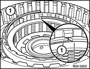
2 Unscrew bolts and remove oil pan. Clean sealing surfaces. Use new gasket. Tightening torque, refer to Technical Data AZ. Remove oil container (1) with magnetic disc (2). Clean magnetic disc. Unfasten screw and remove impulse sensor (1) and retaining clip (2). Note cable routing. Tightening torque, refer to Technical Data AZ. Unfasten screws and remove oil strainer. If necessary, replace oil strainer. Tightening torque, refer to Technical Data AZ. Issue status (01/2005) Valid only until next CD is issued Copyright Page - 2 -


3 Replace O-ring. For ease of installation, coat O-ring with Vaseline. Remove retaining clip and press cable connector into transmission case. Note installation position in connector housing. Replace O-rings. For ease of installation, coat O-rings with Vaseline. Issue status (01/2005) Valid only until next CD is issued Copyright Page - 3 -


.")
4 Unfasten all screws with large heads (12 off) Lift off shift unit. The shift unit must lie flat. Evenly tighten down screws in several passes. Tightening torque, refer to Technical Data AZ. When fitting the shift unit, insert spigot of detent disc in groove of slide valve. Remove suction and pressure pipes from shift unit and replace all O-rings. For ease of installation, coat O-rings with Vaseline. Install the suction and pressure pipes into the transmission housing. Upend the transmission (converter bell housing upward). Unfasten retaining screws on oil supply unit. Replace sealing rings(1). Screws (2) on oil duct M6 x 65, remaining screws M6 x 40. Tightening torque, refer to Technical Data AZ. Issue status (01/2005) Valid only until next CD is issued Copyright Page - 4 -
. Replace damaged rectangular rings (2).")
 flush into the grooves.")

, needle bearing (2) and angle disc (3).")
5 Clamp special tool on stator shaft. Remove oil supply line from transmission case. Replace O-ring (1). Replace damaged rectangular rings (2). For ease of installation, coat O-ring (1) and rectangular rings (2) with Vaseline. Push the rectangular rings (2) flush into the grooves. Suction and pressure ducts in oil supply unit must be aligned with bore in transmission case. Caution! If the rectangular rings (2) are too high, they can be damaged during the installation of the oil supply unit. Remove adjusting disc (1), needle bearing (2) and angle disc (3). End float is adjusted with shim (1). Adjust end float: Install and tighten down oil supply unit. Secure special tool to stator shaft. Issue status (01/2005) Valid only until next CD is issued Copyright Page - 5 -


. 1. Tighten screws (A) M6x40 crosswise. 2. Tighten screw (B) M5x50.")
6 Fit and secure special tool with dial gauge to the input shaft. Fit measuring probe to special tool with slight preload. Zeroise measuring scale. Withdraw input shaft as far as stop and read off measuring value. Adjust end float to mm. If necessary, remove oil supply unit again and install thicker or thinner shim. Check with special tool that pump wheel on oil pump is able to rotate easily. Unfasten screws (A and B). 1. Tighten screws (A) M6x40 crosswise. 2. Tighten screw (B) M5x50. Tightening torque, refer to Technical Data AZ. Issue status (01/2005) Valid only until next CD is issued Copyright Page - 6 -
 in oil supply housing. Replace O-ring (2).")
 (two M6x60 screws without screw head) in pump housing.")

. Pry out shaft seal (2) with a screwdriver.")
7 Remove oil pump from oil supply housing with cotter pin extractor and plastic hammer. Insert dowel pin (1) in oil supply housing. Replace O-ring (2). For ease of installation, coat O-ring with Vaseline. Screw assembly tool (3) (two M6x60 screws without screw head) in pump housing. Remove pump wheel (1) and ring gear (2) from pump housing. Insert pump wheel and ring gear with Vaseline in pump housing. When installed, markings on pump wheel and ring gear must be clearly visible. Lift out snap ring (1). Pry out shaft seal (2) with a screwdriver. Remove thrust washer (3). Issue status (01/2005) Valid only until next CD is issued Copyright Page - 7 -
 with automatic-transmission oil.")

 with special tool 24 1 010.")

8 Install thrust washer (3). Coat new shaft seal (2) with automatic-transmission oil. Drive in shaft seal with special tool Press out seal and needle bearing with special tool and on hydraulic press. Insert seal (1) in pump housing. Press in needle bearing (2) with special tool Clutches (A/B/C): Fit special tool to the input shaft and secure with pin. Lift out drive unit with clutches (A/B/C) using a workshop crane and place on 2 wooden blocks. Issue status (01/2005) Valid only until next CD is issued Copyright Page - 8 -

 to and fro with a screwdriver until it engages fully in discs of")
. Secure axial needle bearing (1) with Vaseline.")
 are too high, they can be damaged during installation.")
9 The impulse spring on the top clutch housing must be located in centre of bore for impulse sensor. Lower drive unit with clutches (A/B/C) into transmission case with a workshop crane. Twist disc carrier D (1) to and fro with a screwdriver until it engages fully in discs of D brake. Place drive unit with clutches (A/B/C) on its head. Remove axial needle bearing (1). Secure axial needle bearing (1) with Vaseline. Coat the rectangular rings (2) with Vaseline and push them into the grooves. Caution! If the rectangular rings (2) are too high, they can be damaged during installation. Bend back retaining tabs with special tool Issue status (01/2005) Valid only until next CD is issued Copyright Page - 9 -

. Note installation position of axial needle bearing (1).")
10 Do not reuse bent retaining tabs for securing purposes. Using special tool , first bend two opposing retaining tabs, then 4 more retaining tabs at regularly spaced intervals. Remove sun shaft (1). Tension disc carrier C upwards with special tool Remove axial needle bearing (1). Note installation position of axial needle bearing (1). Coat rectangular ring (2) with Vaseline. Issue status (01/2005) Valid only until next CD is issued Copyright Page
 by rotating to and fro.")
 from idler shaft (4).")
 in A clutch (2), rotating it to do so.")

11 Lift off idler shaft (1) with clutch B (2). Install clutch B (2) by rotating to and fro. Remove B clutch (1), angled disc (2) and axial needle bearing (3) from idler shaft (4). Note installation position of angled disc (2). Install idler shaft (1) in A clutch (2), rotating it to do so. Lift out snap ring (1) from B clutch and remove complete disc pack. Note installation position of snap ring ends. Align lined discs. Issue status (01/2005) Valid only until next CD is issued Copyright Page
 and angled disc (2) from")

 and install at the same location.")
 from A clutch.")
12 1. Circlip 2. Outer discs 3. Lined discs Remove axial needle bearing (1) and angled disc (2) from cylinder C (3). Lift snap ring (1) out of A clutch. Note: The axial play of the A clutch is factory set over the thickness of the snap ring (1). Mark the snap ring (1) and install at the same location. Note installation position of snap ring ends. Align discs on A clutch. Remove end disc (1) from A clutch. Note: The end disc (1) can be identified by its longer teeth. Issue status (01/2005) Valid only until next CD is issued Copyright Page
.")

 out of C clutch and")

13 Remove internal disc carrier B (1). Remove disc carrier C (1). Install disc carrier C (1), rotating it to do so. Remove complete disc pack from A clutch. 1. Spring disc 2. Outer discs 3. Lined discs Lift snap ring (1) out of C clutch and remove complete disc pack. Note installation position of snap ring ends. Align lined discs. Issue status (01/2005) Valid only until next CD is issued Copyright Page
 Press input shaft (1) out of cylinder A + C.")
 and rectangular rings (3) with")

.")
14 1. Circlip 2. Spring disc 3. Outer discs 4. Lined discs 5. Top outer disc (thicker) Press input shaft (1) out of cylinder A + C. Replace O-ring (2). Replace damaged rectangular rings (3). For ease of assembly, coat O-ring (2) and rectangular rings (3) with Vaseline. D brake/e1/e2 and planetary gear set: Arrange transmission horizontally. Unscrew bolts. Tightening torque, refer to Technical Data AZ. Pull off transmission extension (1). Replace O-ring For ease of assembly, coat O-ring with Vaseline. Issue status (01/2005) Valid only until next CD is issued Copyright Page


 with a screwdriver until it locates in housing of planetary gear set")
15 Remove shim (1) and sprag wheel (2). End float is adjusted with the shim (1). Adjust end float, refer to Arrange transmission vertically with output end facing downwards. Unscrew bolts. Tightening torque, refer to Technical Data AZ. Screw special tool into planetary gear set, tighten down knurled screw. Note: Cylinder D/E (1) and the planetary gear set are held together by tightening down the knurled screw. Lift out complete unit with a workshop crane and place on two wooden blocks. Twist spline (2) with a screwdriver until it locates in housing of planetary gear set (1). Issue status (01/2005) Valid only until next CD is issued Copyright Page
 with bores in transmission case. Carefully insert complete unit. Caution!")

 approx. 45mm. Lift out snap ring (1) from multi-disc brake D and remove complete disc pack.")
16 For ease of assembly, coat perimeter of cylinder D/E (1) with Vaseline. Align threaded bores in cylinder D/E (1) with bores in transmission case. Carefully insert complete unit. Caution! Do not abut against transmission case. Remove special tool. Lift off cylinder D/E (1). Fit cylinder D/E with aligned discs on the planetary drive. Twist housing of planetary gear set to and fro briskly until discs on multi-disc brakes engage completely in the spline teeth. Control dimension (A) approx. 45mm. Lift out snap ring (1) from multi-disc brake D and remove complete disc pack. Note installation position of snap ring ends. Align lined discs. Issue status (01/2005) Valid only until next CD is issued Copyright Page
 Lift snap ring (1) out of multi-disc")

 Valid only until next CD is issued Copyright")
17 1. Circlip 2. Spring disc 3. Outer discs 4. Lined discs 5. Top outer disc (may be thicker) Lift snap ring (1) out of multi-disc brake E2 and remove complete disc pack. Note installation position of snap ring ends. Align lined discs. 1. Circlip 2. Spring disc 3. Outer discs 4. Lined discs 5. Top outer disc (may be thicker) Lift snap ring (1) out of multi-disc brake E1 and remove complete disc pack. Note installation position of snap ring ends. Align lined discs. Issue status (01/2005) Valid only until next CD is issued Copyright Page
 Remove angled disc (1) and axial needle bearing (2).")


18 1. Circlip 2. Spring disc 3. Outer discs 4. Lined discs 5. Top outer disc (thicker) Remove angled disc (1) and axial needle bearing (2). Lift freewheel off 2nd gear (1). Note: Fitted freewheel must lock in clockwise direction and should be easy to rotate in anti-clockwise direction. Lift out disc carrier E2 (1). For ease of assembly, coat disc carrier, O-ring and sealing face with Vaseline. Issue status (01/2005) Valid only until next CD is issued Copyright Page


. Note installation position of snap ring ends. Lift out planet spider II (1).")
19 Lift planetary gear set I + II (1) off planetary gear set III (2). Rotate planetary gear set I + II to fit on planetary gear set III. Remove sun gear II + III (1) from planet carrier III (2). Install sun gear, rotating to do so. Place planetary gear set I + II on two wooden blocks Lift out snap ring (1) and remove ring gear III (2). Note installation position of snap ring ends. Lift out planet spider II (1). Replace O-ring. For ease of assembly, coat O-ring with Vaseline. Issue status (01/2005) Valid only until next CD is issued Copyright Page
. Note installation position.")

 from planet spider I (2).")

20 Remove thrust washer (1), axial needle bearing (2) and angled disc (3). Note installation position. Note: When removing the sun gear, check whether marking groove in sun gear is facing upwards or downwards. The sun gear (1) must be installed in the same position. Remove sun gear I (1) from planet spider I (2). Lift out snap ring (1). Note installation position of snap ring ends. Remove planet spider I (1) and ring gear II (2) from ring gear I (3). Issue status (01/2005) Valid only until next CD is issued Copyright Page


.")
21 Lift out snap ring (1). Remove planet spider I (2) from ring gear II (3). Replace O-ring. Note installation position of snap ring ends. Arrange transmission horizontally. Unscrew bolts. Note: If necessary, strike screws when unfastening. Tightening torque, refer to Technical Data AZ. Arrange transmission vertically with output end facing downwards. Secure special tool to cylinder F (1). Pull out cylinder F (1). When installing cylinder F, insert guide bolts in two bores beside bore (B). Bore (A) in cylinder F and bore (B) in transmission case must be aligned. Issue status (01/2005) Valid only until next CD is issued Copyright Page
. Replace O-ring.")

 out of multi-disc brake F (3).")

22 Screw the guide bolts (1) (2 bolts M8x70 without bolt heads) into cylinder F, each next to the bore (A). Replace O-ring. For ease of assembly, coat grey area with Vaseline. Freewheel on 1st gear must rotate easily in clockwise direction and should lock when turned anti-clockwise. Lift out snap ring (1). Lift freewheel for 1st gear (2) out of multi-disc brake F (3). Lift snap ring (1) out of multi-disc brake F (2) and remove complete disc pack. Note installation position of snap ring ends. Align lined discs. Issue status (01/2005) Valid only until next CD is issued Copyright Page
 Issue status (01/2005) Valid only until next CD is")
23 1. Circlip 2. Spring disc 3. Outer discs 4. Lined discs 5. Top outer disc (thicker) Issue status (01/2005) Valid only until next CD is issued Copyright Page
REPAIR MANUAL 5 HP - 30 ZF GETRIEBE GMBH SAARBRÜCKEN
 REPAIR MANUAL 5 HP - 30 ZF GETRIEBE GMBH SAARBRÜCKEN Impressum: Verantwortlich für den Inhalt Abteilung MKTD, ZF Getriebe GmbH, Saarbrücken Druck: HAGER PAPPRINT GmbH, Gedruckt in der BRD Published by
Pull out clutch E snap ring and withdraw complete clutch pack of clutch E. 6 HP 26 ZF Getriebe GmbH Saarbrücken CD
 Press down cup spring in the mandrel press with assembly bracket 5x46 002 566 and remove snap ring with suitable pliers. Take out planet carrier and cup spring. Take the O-ring seal off the planet carrier.
Take off case cover.
 33 14 520 Removing complete locking differential. (Type K) - final drive removed - Removing and installing final drive, refer to 33 10 010 Drain off fluid. Secure final drive to special tool 33 1 010 (retaining
Take off case cover.
 33 14 520 Replacing complete locking differential (Type M) - final drive removed - Removing and installing final drive, included in Repair Manual MF, model-dependent, from '85, refer to 33 10 010. Drain
REPAIR MANUAL. Version 02/11/01 CD ZF GETRIEBE GMBH SAARBRÜCKEN
 REPAIR MANUAL 6 HP-26 Version CD ZF GETRIEBE GMBH SAARBRÜCKEN subject to alterations Copyright 2002 all rights reserved and published by ZF Getriebe GmbH, Saarbrücken, Department MKTD No part of this manual
2003 E-Series Workshop Manual
 Page 1 of 20 SECTION 307-01B: Automatic Transmission 4R70W 2003 E-Series Workshop Manual ASSEMBLY Procedure revision date: 04/27/2006 Transmission Printable View (1828 KB) Special Tool(s) Dial Indicator
Turn cylinder CD by 180. Pull 2 O-ring seals and onto piston C and press it into the cylinder.
 Turn cylinder CD by 180. Pull 2 O-ring seals 75.040 and 75.050 onto piston C 75.030 and press it into the cylinder. 01276 Insert cup spring C 75.070 and retaining ring 75.080. Press down cup spring C in
2007 Dodge Nitro R/T
 ASSEMBLY AUTOMATIC TRANSMISSION - 42RLE NOTE: If the transmission assembly is being reconditioned (clutch/seal replacement) or replaced, it is necessary to perform the TCM QUICK LEARN Procedure using the
Oil pan, oil strainer and valve body, removing and installing
 Page 1 of 44 38-1 Oil pan, oil strainer and valve body, removing and installing WARNING! Do not run engine with the oil pan removed or without ATF filling and do not tow vehicle. Notes: Always replace
Repair Manual VW 02J gearbox. INA GearBOX
 Repair Manual VW 02J gearbox INA GearBOX Special tools Pipe section, 50 mm: Press fitting of synchronizer body for third/fourth gear. Assembly of support bearing for input and output shaft. Part number:
Description and Operation
 Description and Operation Clean the automatic transmission to prevent dirt entering when it is reassembled. Lay the removed parts out clearly to make it easier to assess damage and reassemble components.
DISASSEMBLY AND ASSEMBLY
 307-01-1 Automatic Transaxle/Transmission 307-01-1 DISASSEMBLY AND ASSEMBLY Transaxle Special Tool(s) Dial Indicator Gauge With Holding Fixture 100-002 (TOOL-4201-C) Special Tool(s) Test Plate Screw Set,
2007 Jeep Truck Liberty 4WD V6 3.7L VIN K
 2007 Jeep Truck Liberty 4WD V6 3.7L VIN K Vehicle» Transmission and Drivetrain» Automatic Transmission/Transaxle» Service and Repair» Overhaul» Assembly ASSEMBLY NOTE: If the transmission assembly is being
REPAIR MANUAL. W 390 MS torque converter a
 REPAIR MANUAL W 390 MS 449 75 606a Subject to technical changes Copyright by ZF This documentation is protected by copyright. Any reproduction and dissemination in whatever form also in adapted, paraphrased
ASSEMBLY PROCEDURE. Transmission
 67 ASSEMBLY PROCEDURE Transmission Tools Required 0555-336256 Transmission Bench Cradle 0555-336258 Cross Shaft Pin Remover/Installer (Detent Lever) 0555-336262 Cross Shaft Seal Installer 0555-336263 Cross
DISASSEMBLY. Transmission. All vehicles
 307-01-1 Automatic Transmission 5R44E and 5R55E 307-01-1 DISASSEMBLY Transmission Special Tool(s) Holding Fixture, Transmission 307-262 (T93T-77002-AH) Special Tool(s) Remover, Servo 307-347 (T97T-7D021-A)
Transaxle. 1. Mount the transaxle to Bench Mounted Holding Fixture T57L-500-B.
 «1997 Aspire Table of Contents» «Group 07: TRANSAXLE» «Section 07-01: Transaxle, Automatic» «DISASSEMBLY» Transaxle CAUTION: To prevent dirt from entering the transaxle, it should be disassembled and kept
ASSEMBLY. Transmission Automatic Transmission 5R44E and 5R55E. Special Tool(s)
") 307-01-1 Automatic Transmission 5R44E and 5R55E 307-01-1 ASSEMBLY Transmission Special Tool(s) Holding Fixture, Transmission 307-262 (T93T-77002-AH) Special Tool(s) Installer, Transmission Extension Housing
307-01-1 Automatic Transmission 5R44E and 5R55E 307-01-1 ASSEMBLY Transmission Special Tool(s) Holding Fixture, Transmission 307-262 (T93T-77002-AH) Special Tool(s) Installer, Transmission Extension Housing
1. General Description
 1. General Description A: SPECIFICATION 1. MANUAL TRANSMISSION AND FRONT DIFFERENTIAL Type Transmission gear ratio Front reduction gear Rear reduction gear Front differential Center differential Final
ASSEMBLY PROCEDURE AUTOMATIC TRANSMISSION 5A-173. Transmission
 AUTOMATIC TRANSMISSION 5A-173 ASSEMBLY PROCEDURE Transmission Tools Required 0555-336256 Transmission Bench Cradle 0555-336258 Cross Shaft Pin Remover/Installer (Detent Lever) 0555-336262 Cross Shaft Seal
 Page 1 of 22 SECTION 307-01: Automatic Transaxle/Transmission 4R70E/4R75E ASSEMBLY Procedure revision date: 05/29/2009 Transmission Printable View (1554 KB) Special Tool(s) Air Test Plate, Transmission
23. Planetary Gear and Low Clutch S510212
 Automatic Transmission 23. Planetary Gear and Low Clutch S510212 A: REMOVAL S510212A18 1) Extract the torque converter clutch assembly. 2) Remove
HIGH PERFORMANCE TRANSMISSION PARTS Instructions. Line Pressure Booster Kit. TCC Control Plunger Valve Kit. Line Pressure Modulator Plunger Valve Kit
 Performance Pack Ford 4R100 Part No. HP-4R100-01 Line Pressure Booster Kit Line-to-Lube Pressure Regulator Valve Line Pressure Booster Kit Valve Sleeve O-Rings (2) TCC Control Plunger Valve Kit Front Lube/Drainback
LoMax 205 CASE & 3:1 GEAR SET. Manufactured by JB CONVERSIONS, INC. Phone: Installation Instructions for the GM NP205 Transfer Case
 LoMax 205 CASE & 3:1 GEAR SET Part No. 2800 Instruction Rev: 2007.08.16 Manufactured by JB CONVERSIONS, INC. Phone: Installation Instructions for the GM NP205 Transfer Case Kit Components: 1. (1) 42x25
ASSEMBLY. Transmission Automatic Transaxle/Transmission. Special Tool(s) Alignment Set, Fluid Pump 307-S039 (T74P X) Special Tool(s)
 Alignment Set, Fluid Pump 307-S039 (T74P X) Special Tool(s)") 307-01-1 Automatic Transaxle/Transmission 307-01-1 ASSEMBLY Transmission Special Tool(s) Adjustment Set, Transmission Band 307-S022 (T71P-77370-A) Special Tool(s) Alignment Set, Fluid Pump 307-S039 (T74P-77103-X)
307-01-1 Automatic Transaxle/Transmission 307-01-1 ASSEMBLY Transmission Special Tool(s) Adjustment Set, Transmission Band 307-S022 (T71P-77370-A) Special Tool(s) Alignment Set, Fluid Pump 307-S039 (T74P-77103-X)
HIGH PERFORMANCE TRANSMISSION PARTS Instructions. Line Pressure Booster Kit. TCC Control Plunger Valve Kit. Line Pressure Modulator Plunger Valve Kit
 Performance Pack Ford 4R100 Part No. HP-4R100-01 Line Pressure Booster Kit Line-to-Lube Pressure Regulator Valve Line Pressure Booster Kit Valve Sleeve O-Rings (2) TCC Control Plunger Valve Kit Front Lube/Drainback
Jatco 5 Speed ATRA. All Rights Reserved. Printed in U.S.A.
 1 2 3 Table Of Contents Transmission Diassembly... 4 Front Pump... 16 Reverse/High Clutch Drum... 18 Direct Clutch Drum... 22 Low Clutch Drum... 26 Planetary Gearsets... 29 Transfer Gear/Reduction Gear...
2005 Toyota RAV AUTOMATIC TRANSMISSIONS U240E & U241E Overhaul
 2001-05 AUTOMATIC TRANSMISSIONS U240E & U241E Overhaul APPLICATION CAUTION: Flush oil cooler and oil cooler lines prior to transaxle installation. Oil cooling system contamination may cause premature transaxle
SECTION 5B MANUAL TRANSMISSION TABLE OF CONTENTS
 SECTION 5B MANUAL TRANSMISSION TABLE OF CONTENTS General Description and Operation... 5B-2 Shift Lever... 5B-2 Transmission Assembly... 5B-2 Specifications... 5B-3 Diagnostic Information and Procedures...
Volkswagen New Beetle 2.0 Liter 4-cyl General, Engine (Engine Code AEG) 13 Engine-Crankshaft, Cylinder block (Page GR-13)
 13 Engine-Crankshaft, Cylinder block (Page GR-13)") 13 Engine-Crankshaft, Cylinder block (Page GR-13) Engine, disassembly and assembly 10-222 A/21 guide from 10-222 A support tool, modifying Ribbed belt, removing and installing Semi-automatic toothed belt
13 Engine-Crankshaft, Cylinder block (Page GR-13) Engine, disassembly and assembly 10-222 A/21 guide from 10-222 A support tool, modifying Ribbed belt, removing and installing Semi-automatic toothed belt
Output Shaft Assembly COMPONENTS
 MT140 Component Parts (Output Shaft Assembly Output Shaft Assembly COMPONENTS DISASSEMBLY OF OUTPUT SHAFT ASSEMBLY 1. REMOVE SLEEVE FROM OUTPUT SHAFT Using SST, remove the sleeve from the output shaft.
ABBREVIATIONS USED IN THIS MANUAL
 IN6 INTRODUCTION Abbreviations Used in This Manual ABBREVIATIONS USED IN THIS MANUAL A/T ATM Automatic Transmission ATF Automatic Transmission Fluid B 0 Overdrive Brake B 1 Second Coast Brake B 2 Second
1988 Jeep Truck Wrangler L L VIN H TBI Copyright 2013, ALLDATA 10.52SS Page 1 Technical Service Bulletin # Date:
 1988 Jeep Truck Wrangler L4-150 2.5L VIN H TBI Copyright 2013, ALLDATA 10.52SS Page 1 Technical Service Bulletin # 025288 Date: 880711 Right Front Axle Shaft Seal - Installation Models 1986-88 Jeep Comanche,
Transmission Overhaul Procedures-Bench Service
 How to Install the Auxiliary Countershaft Assembly Special Instructions To make auxiliary section assembly easier, you can make an auxiliary section fixture out of a 2" x 12" piece of wood. 3' 1' 3" 4.56"
NOTE: Clean and inspect all components. Replace any components which show evidence of excessive wear or scoring.
 ASSEMBLY (AUTOMATIC 545RFE)... ASSEMBLY NOTE: Apply trans jell or petroleum jelly to all slide portions, rolling contacts surfaces, thrust surfaces etc. to prevent burnout during initial operation. Lubricate
AUTOMATIC TRANSAXLE AUTOMATIC TRANSAXLE SYSTEM... COMPONENT PARTS...
 SYSTEM....... COMPONENT PARTS.................... OIL PUMP.............................. DIRECT CLUTCH........................ FORWARD CLUTCH..................... SECOND BRAKE........................ UNDERDRIVE
SISU DP-330 DRIVE GEAR. Maintenance Manual
 SISU DP-330 DRIVE GEAR Maintenance Manual Sisu Axles, Inc. Autotehtaantie 1 PO Box 189 Fin-13101 Hameenlinna Finland Phone +358 204 55 2999 Fax +358 204 55 2900 DP330DG.PDF (3/2007) TABLE OF CONTENTS
Direct Shift Gearbox (DSG) Mechatronic unit J743, removing and installing. - Loosen bolts - arrows - of oil pan - A - in diagonal sequence and remove.
 Mechatronic unit J743, removing and installing. - Loosen bolts - arrows - of oil pan - A - in diagonal sequence and remove.") - Loosen bolts - arrows - of oil pan - A - in diagonal sequence and remove. Note: Some transmission oil remains in the oil pan because not all of it can drain out. - Remove oil pan together with oil pan
- Loosen bolts - arrows - of oil pan - A - in diagonal sequence and remove. Note: Some transmission oil remains in the oil pan because not all of it can drain out. - Remove oil pan together with oil pan
2002 F-Super Duty /Excursion Workshop Manual
 Page 1 of 25 SECTION 307-01: Automatic Transaxle/Transmission 2002 F-Super Duty 250-550/Excursion Workshop Manual ASSEMBLY Procedure revision date: 05/23/2001 Transmission Special Tool(s) Remover, O-Ring
LuK Repair Solution for manual transmissions. Disassembly and assembly Special tool/failure diagnosis VW 02J
 LuK Repair Solution for manual transmissions Disassembly and assembly Special tool/failure diagnosis VW 02J The content of this brochure shall not be legally binding and is for information purposes only.
Assembly. NOTE: Before beginning assembly, perform/inspect the following:
 Page 1 of 31 Home Account Contact ALLDATA Log Out Help DAN GRIMWOOD DAN GRIMWOOD00002 Select Vehicle New TSBs Technician's Reference Component Search: OK 1997 Ford Truck F 150 2WD Pickup V6-4.2L VIN 2
DISASSEMBLY. Transmission. 2. Remove the 4 clutch housing bolts. Separate the clutch housing from the transmission.
 308-03A-1 DISASSEMBLY Transmission 308-03A-1 Special Tool(s) Puller, Bearing 205-D064 (D84L-1123-A) or equivalent Remover/Installer, Front Wheel Hub 204-069 (T81P-1104-C) 2. Remove the 4 clutch housing
REPAIR MANUAL HP-19 FL/A ZF GETRIEBE GMBH SAARBRÜCKEN. Versione00/08/01 CD
 REPAIR MANUAL 5 HP-19 FL/A Versione00/08/01 CD ZF GETRIEBE GMBH SAARBRÜCKEN subject to alterations Copyright 2000 all rights reserved and published by ZF Getriebe GmbH, Saarbrücken, Department MKTD No
Maintenance Information
 Form 04584058 Edition 1 November 2004 Air Impactool 2141P and 2141PSP Maintenance Information Save These Instructions Disassembly General Instructions 1. Do not disassemble the tool any further than necessary
SECTION Automatic Transaxle/Transmission 6R80
 307-01-i Automatic Transaxle/Transmission 6R80 307-01-i SECTION 307-01 Automatic Transaxle/Transmission 6R80 CONTENTS PAGE Transmission... 307-01-2 307-01-2 Automatic Transaxle/Transmission 6R80 307-01-2
 Page 1 of 15 Transmission, Model S5-42 ZF Model S5-42 ZF Disassembly NOTE: For 4x4 and F-Super Duty vehicles, skip to Step 5. 1. Attach the transmission to the Bench Mounted Holding Fixture T57L-500-B
HOLINGER SF GEARBOX MANUAL
 HOLINGER SF GEARBOX MANUAL Approved By: Leigh Nash Date: 26/05/2011 Rev: D Date: 11/11 Holinger Engineering Gearbox Manual Page 1 FOREWORD The Holinger SF is a sequential-shift transaxle designed for use
DISASSEMBLY AND ASSEMBLY
 205-03-1 Front Drive Axle/Differential Ford 8.8-Inch Ring Gear 205-03-1 DISASSEMBLY AND ASSEMBLY Axle Front Drive Special Tool(s) 2-Jaw Puller 205-D072 (D97L-4221-A) Special Tool(s) Carrier Bearing Replacer
DISASSEMBLY AND ASSEMBLY (Continued)
") 205-03-23 Front Drive Axle/Differential Ford 8.8-Inch Ring Gear 205-03-23 49. Measure the ring gear backlash at four places to obtain a consistent reading. 1 Mount the special tools on the indicator base.
205-03-23 Front Drive Axle/Differential Ford 8.8-Inch Ring Gear 205-03-23 49. Measure the ring gear backlash at four places to obtain a consistent reading. 1 Mount the special tools on the indicator base.
Disassembling and assembling transmission
 27-640 Disassembling and assembling transmission Preceding work: Removing and installing transmission with torque converter (27-600). Operation number of operation texts and operation values or standard
1999 F-150/250 Workshop Manual
 Page 1 of 30 SECTION 205-03: Front Drive Axle/Differential Ford 8.8-Inch Ring Gear 1999 F-150/250 Workshop Manual DISASSEMBLY AND ASSEMBLY Procedure revision date: 01/08/2003 Axle Front Drive Special Tool(s)
BRAKE SYSTEM Nissan 240SX DESCRIPTION BRAKE BLEEDING * PLEASE READ FIRST * BLEEDING PROCEDURES ADJUSTMENTS BRAKE PEDAL HEIGHT SPECS TABLE
 BRAKE SYSTEM 1990 Nissan 240SX 1990 BRAKE SYSTEMS Nissan Disc & Drum Axxess, Maxima, Pathfinder, Pickup, Pulsar NX, Sentra, Stanza, 240SX, 300ZX DESCRIPTION All brake systems are hydraulically operated
REMOVAL TF REMOVE TRANSFER INDICATOR SWITCH (a) Remove the switches and gaskets. HINT: Indicator switch:
 Remove the switches and gaskets. HINT: Indicator switch:") 20 NO. 1 NO. 2 F043499 REMOVAL 1. DISCONNECT CABLE FROM NEGATIVE BATTERY TERMINAL CAUTION: Wait at least 90 seconds after disconnecting the cable from the negative (-) battery terminal to prevent airbag
20 NO. 1 NO. 2 F043499 REMOVAL 1. DISCONNECT CABLE FROM NEGATIVE BATTERY TERMINAL CAUTION: Wait at least 90 seconds after disconnecting the cable from the negative (-) battery terminal to prevent airbag
OVERHAUL. 1. INSPECT 1ST GEAR THRUST CLEARANCE (a) Using a feeler gauge, measure the 1st gear thrust clearance.
 Using a feeler gauge, measure the 1st gear thrust clearance.") 4168 OVERHAUL 410F701 1. INSPECT 1ST GEAR THRUST CLEARANCE (a) Using a feeler gauge, measure the 1st gear thrust clearance. 0.10 to 0.40 mm (0.0039 to 0.0157 in.) 0.40 mm (0.0157 in.) C80538 2. INSPECT
4168 OVERHAUL 410F701 1. INSPECT 1ST GEAR THRUST CLEARANCE (a) Using a feeler gauge, measure the 1st gear thrust clearance. 0.10 to 0.40 mm (0.0039 to 0.0157 in.) 0.40 mm (0.0157 in.) C80538 2. INSPECT
SECTION Automatic Transaxle/Transmission 6R80
 307-01-i Automatic Transaxle/Transmission 6R80 307-01-i SECTION 307-01 Automatic Transaxle/Transmission 6R80 CONTENTS PAGE Forward Clutch Assembly... 307-01-2 307-01-2 Automatic Transaxle/Transmission
Service Manual. Example Part Number. Motor Supplier. Motor Number. Model. Bail Boss. Ratio. Shaft
 Service Manual 50 Series Digger models Example Part Number 50 05 f 54 Model Ratio Shaft Bail Boss Motor Supplier Motor Number This service manual is effective: S/N: 58670 to current date: 9-003 to CURRENT
INSTALLATION GUIDE. KTM 125, 144, Stroke KTM 250, Stroke KTM 250 SXF, XC, XC-W KTM 450, 505 SXF Manual Revision:
 REKLUSE MOTOR SPORTS The z-start Pro Clutch INSTALLATION GUIDE KTM 125, 144, 200 2-Stroke KTM 250, 300 2-Stroke KTM 250 SXF, XC, XC-W KTM 450, 505 SXF 191-836 Manual Revision: 050307 2002 Rekluse Motor
TABLE OF CONTENTS 0 FRONT DRIVE , WHEEL HUB , WHEEL HUB BEARING , KNUCKLE
 Subsection 01 (TABLE OF CONTENTS) TABLE OF CONTENTS 0 FRONT DRIVE... 06-02-1 1, WHEEL HUB... 06-02-2 2, WHEEL HUB BEARING... 06-02-2, KNUCKLE... 06-02- FINAL DRIVE... 06-0-1 1, DRIVE CHAIN... 06-0-2 2,
Technical Service Bulletin
 Page 1 of 41 MITSUBISHI MOTORS Technical Service Bulletin SUBJECT No: NOISE FROM CVT AT ALL ENGINE SPEEDS DATE: February, 2015 MODEL: See below CIRCULATE TO: I[ ]GENERAL MANAGER I [ X l PARTS MANAGER I
Off-Highway Axle Planetary Wheel Ends
 Maintenance Manual MM-1189 Off-Highway Axle Planetary Wheel Ends Revised 06-16 Service Notes About This Manual This manual provides service and repair procedures for planetary wheel ends on off-highway
REPAIR INSTRUCTIONS ON-VEHICLE SERVICE TRANSMISSION AUTOMATIC TRANSMISSION 5A-159. Removal and Installation Procedure
 REPAIR INSTRUCTIONS YAD5A080 AUTOMATIC TRANSMISSION 5A-159 ON-VEHICLE SERVICE TRANSMISSION Removal and Installation Procedure 1. Disconnect the negative battery cable. 2. Disconnect the connectors from
REAR DIFFERENTIAL LOCATION INDEX
 2007 DRIVELINE/AXLES Differential - MX-5 Miata REAR DIFFERENTIAL LOCATION INDEX Fig. 1: Identifying Location Of Rear Differential Components DIFFERENTIAL OIL INSPECTION 1. Park the vehicle on level ground
MAINTENANCE MANUAL DP-265
 MAINTENANCE MANUAL DP-265 Drive Gears Sisu Axles, Inc. Autotehtaantie 1 P.O. Box 189 FIN-13101 Hämeenlinna Finland Phone int + 358 204 55 2999 Fax int + 358 204 55 2900 DP265DG.PDF (2/2003) k Table of
Maintenance Information
 16584062 Edition 3 December 2013 High Torque Reversible Angle Screwdrivers and Angle Wrenches QA1L High Torque Series Maintenance Information Save These Instructions Product Safety Information WARNING
Maintenance Manual FP-330 Drive Gear
 Maintenance Manual FP-330 Drive Gear Sisu Axles, Inc. Autotehtaantie 1 P.O. Box 189 FIN-13101 Hämeenlinna Finland Phone int + 358 204 55 2999 Fax int + 358 204 55 2900 FP330DG 2/2008 Maintenance Manual
INSTALLATION GUIDE Manual Revision:
 REKLUSE MOTOR SPORTS The z-start Pro Clutch INSTALLATION GUIDE KTM 125, 144, 200 2-Stroke KTM 250, 300 2-Stroke KTM 250 SXF, XC, XC-W KTM 400 XC-W KTM 450, 505 SXF, XC-F KTM 450, 530 XCR-W, EXC-R Husaberg
Engine Dismantle and Assemble ( )
") Engine Dismantle and Assemble (21 134 8) Special Tools 15-030A Universal flange-holding wrench 21147 21-147 Vibration damper remover 15030A 16-067 Locator for clutch disc 21-167 Wrench for cylinder head
Engine Dismantle and Assemble (21 134 8) Special Tools 15-030A Universal flange-holding wrench 21147 21-147 Vibration damper remover 15030A 16-067 Locator for clutch disc 21-167 Wrench for cylinder head
SECTION B Manual Transaxle/Transmission TR6060
 308-03B-i Manual Transaxle/Transmission TR6060 308-03B-i SECTION 308-03B Manual Transaxle/Transmission TR6060 CONTENTS PAGE Transmission... 308-03B-2 308-03B-2 Manual Transaxle/Transmission TR6060 308-03B-2
3.2 DRIVE TORQUE HUB. Roll, Leak and Brake Testing SECTION 3 - CHASSIS & TURNTABLE. 3-2 JLG Lift
 3.2 DRIVE TORQUE HUB Roll, Leak and Brake Testing 10 LUG PATTERN Torque-Hub units should always be roll and leak tested before disassembly and after assembly to make sure that the unit's gears, bearings
1 of 25 9/12/2013 9:07 PM
 1 of 25 9/12/2013 9:07 PM 46RE Automatic Transmission DISASSEMBLY 1. Clean exterior of transmission with suitable solvent or pressure washer. 2. Place transmission in vertical position. 3. Measure the
ABBREVIATIONS USED IN THIS
 IN10 INTRODUCTION ABBREVIATIONS USED IN THIS MANUAL ABBREVIATIONS USED IN THIS MANUAL ATF Automatic Transmission Fluid B 0 Overdrive Brake B 2 Second Brake B 3 No. 3 Brake C 0 Overdrive Direct Clutch C
J2 Remove sound insulation/knee guard 1 and side panel 2 on center console
 J1 Preparations Drive car forward on a level surface so that wheels are straight. Disconnect battery negative lead. Turn ignition key to position 1 so that steering lock is off. J2 Remove sound insulation/knee
Engine Dismantle and Assemble ( )
") Engine Dismantle and Assemble ( 34 8) Special Tools 5 053 Slide hammer 47 Vibration damper remover 47 5053 00 Splined head socket, cylinder head bolts 87 Mounting stand with geared drive 00 059C Installer
Engine Dismantle and Assemble ( 34 8) Special Tools 5 053 Slide hammer 47 Vibration damper remover 47 5053 00 Splined head socket, cylinder head bolts 87 Mounting stand with geared drive 00 059C Installer
NOTE: Clean and inspect all components. Replace any components which show evidence of excessive wear or scoring.
 21 - Transmission and Transfer Case/Automatic - 68RFE/Assembly ASSEMBLY Labor Operations: Click to display a list of Labor Operations associated with this procedure Special Tools: Click to display a list
STERNDRIVE UNIT 3 B GEAR HOUSINGS MR/ALPHA ONE/ALPHA ONE SS
 STERNDRIVE UNIT 3 B 23146 GEAR HOUSINGS MR/ALPHA ONE/ALPHA ONE SS Table of Contents Page Identification........................... 3B-1 Specifications.......................... 3B-1 Torque Specifications................
Maintenance Information
 16575243 Edition 2 October 2013 Air Screwdrivers 1R Series Maintenance Information Save These Instructions Product Safety Information WARNING Failure to observe the following warnings, and to avoid these
SISU MP-330 DRIVE GEAR. Maintenance Manual
 SISU MP-330 DRIVE GEAR Maintenance Manual Sisu Axles, Inc. Autotehtaantie 1 PO Box 189 Fin-13101 Hameenlinna Finland Phone +358 204 55 2999 Fax +358 204 55 2900 MP330DG.PDF (4/2007) TABLE OF CONTENTS
2001 Dodge RAM 3500 PICKUP
 1 of 76 9/14/2012 7:02 PM 2001 Dodge RAM 3500 PICKUP Submodel: Engine Type: L6 Liters: 5.9 Fuel Delivery: FI Fuel: DIESEL Subarticles MANUAL- NV3500 - DISASSEMBLY MANUAL- NV3500 - DISASSEMBLY MANUAL -
OVERHAUL 1. REMOVE CYLINDER BLOCK WATER DRAIN COCK SUB ASSY
 1416 OVERHAUL 1. REMOVE CYLINDER BLOCK WATER DRAIN COCK SUBASSY 140RL01. INSPECT CONNECTING ROD THRUST CLEARANCE (a) Using a dial indicator, measure the thrust clearance while moving the connecting rod
DRIVE SHAFT LOCATION INDEX
 DRIVE SHAFT LOCATION INDEX 2005 DRIVELINE/AXLE Drive Shaft - MX-5 Miata Fig. 1: Identifying Drive Shaft Location DRIVE SHAFT PRE-INSPECTION 1. Inspect the dust boot on the drive shaft for cracks, damage,
RAM P/N AH04415R Double Reduction Wheel Drive SERVICE MANUAL
 RAM P/N AH04415R Double Reduction Wheel Drive SERVICE MANUAL Power Wheel Service Manual Model 7 Double Reduction Wheel Drives AUBURN, INDIANA 46706-3499 U.S.A. PHONE: (219) 925-3200 FAX: (219) 925-4725
DRIVE AXLE Volvo 960 DESCRIPTION & OPERATION AXLE IDENTIFICATION DRIVE AXLES Volvo Differentials & Axle Shafts
 DRIVE AXLE 1994 Volvo 960 1994 DRIVE AXLES Volvo Differentials & Axle Shafts 960 DESCRIPTION & OPERATION All 960 station wagon models use type 1041 rear axle assembly. All 960 4-door models use type 1045
INSTALLATION GUIDE. Clutch Cable Actuated Models Manual Revision:
 REKLUSE MOTOR SPORTS The z-start Pro Clutch INSTALLATION GUIDE Clutch Cable Actuated Models 191-800 Manual Revision: 041513 2012 Rekluse Motor Sports Rekluse Motor Sports, Inc. 12000 W Franklin Rd. Boise,
Geo Prizm ( LSi) Toyota Celica 1.8L (1994)
 Toyota Celica 1.8L (1994)") Page 1 of 140 ARTICLE BEGINNING APPLICATION TRANSMISSION APPLICATIONS Application Geo Prizm (1993-94 LSi) Toyota Celica 1.6L (1993) Celica 1.8L (1994) Celica 2.2L (1993) Corolla 1.8L MR2 Paseo Transaxle
Page 1 of 140 ARTICLE BEGINNING APPLICATION TRANSMISSION APPLICATIONS Application Geo Prizm (1993-94 LSi) Toyota Celica 1.6L (1993) Celica 1.8L (1994) Celica 2.2L (1993) Corolla 1.8L MR2 Paseo Transaxle
AJV8 Engine Assembly. AJV8 Engine Assembly
 AJV8 Engine Assembly Contents Cylinder Block Dowels, Plugs and Pipes 2 4 Crankshaft Bearing and Cylinder Bore Dimensions 5 9 Bearing Measuring 6 Engine Dimensions and Codes 6 7 Main Bearing Selection Chart
ALLISON 1000 SIGNATURE SERIES
 ALLISON 1000 SIGNATURE SERIES 2001-2010 DURAMAX GPZ 1 FLUID CAPACITY INSTALLATION In our RevMax performance transmission we require you to use DEXRON 3 fluid and are shipped empty due to the regulations
BORG WARNER TRANSFER BOX
 BORG WARNER TRANSFER BOX Overhaul Manual BORG WARNER 44-62 TRANSFER BOX OVERHAUL MANUAL This transfer box is used on the following models: New Range Rover Published by Rover Technical Communication 1996
TRANSMISSION PARTS BOOK
 TRANSMISSION PARTS BOOK SS-6, SS-636, SS-836 SS-8, SS-08 DATE: 7-3-96 CLARK 8000 SERIES INTERMEDIATE DROP BARAGA PRODUCTS, INC. 55 N. Superior Ave. Baraga, MI 9908-08 Ph. (906) 353-6675 Fax (906) 353-75J
DRIVE AXLE Nissan 240SX DESCRIPTION & OPERATION AXLE RATIO & IDENTIFICATION AXLE SHAFT & BEARING R & I DRIVE SHAFT R & I
 DRIVE AXLE 1990 Nissan 240SX 1990 DRIVE AXLES Rear Axle - R200 240SX, 300ZX DESCRIPTION & OPERATION The axle assembly is a hypoid type gear with integral carrier housing. The pinion bearing preload adjustment
615 Service Manual SERVICE MANUAL. 615 Series Axle
 SERVICE MANUAL 615 Series Axle Issue 1 - February 2002 CONTENT: 1 INTRODUCTION... Page - 1-2 GENERAL DESCRIPTION... Page - 1-3 IDENTIFICATION... Page - 1-4 GENERAL SERVICE INFORMATION... 4.1 Routine Maintenance...
Skill Module Number: 1.1
 Name Skill Module Number: 1.1 Subject: 722.9 Transmission D & A Objective: At the conclusion of this module, you will be able to: Explain how to disassemble the 722.9 transmission Explain how to assemble
AUTOMATIC TRANSMISSIONS ZF 4HP 18
 AUTO TRANS OVERHAUL - ZF 4HP 18 Article Text 1991 Eagle Premier For Dan's Transmission Service 10 Jefferson Place Fort Walton Beach FL 32548 1997 Mitchell Repair Information Company, All Rights Reserved.
Transmission Overhaul Procedures-Bench Service
 How to Assemble the Lower Reverse Idler Gear Assembly Special Instructions In 1996 Eaton changed the reverse idler system design. In the nut design, the reverse idler bearing was lubricated through a hole
Repair manual - Type 348
 Repair manual - Type 348 Okt 91 1 Engine removal Clean machine and drain off engine oil, disconnect battery. Dismount exhaust manifold, remove chain cover and chain, disconnect clutch and decompressor
Compressor - Install (E.40.C.31 - F.10.A.15)
") Compressor - Install (E.40.C.31 - F.10.A.15) 1. Set the compressor on its mount and secure into place using the four bolts. Connect the refrigerant suction line (5) and the discharge line (4). Install
Compressor - Install (E.40.C.31 - F.10.A.15) 1. Set the compressor on its mount and secure into place using the four bolts. Connect the refrigerant suction line (5) and the discharge line (4). Install
2007 Jeep Truck Liberty 4WD V6 3.7L VIN K
 2007 Jeep Truck Liberty 4WD V6 3.7L VIN K Vehicle» Transmission and Drivetrain» Automatic Transmission/Transaxle» Service and Repair» Overhaul» Disassembly DISASSEMBLY NOTE: If the transmission is being
Disassembly. 1 Pull off the QUIK-LOK cable from the machine.
 Special Tools Require Important! Torx TX0 bit 0 0 Screwdriver Torx 0 0 0 Forcing Discs 0 Before beginning the maintenance work, perform an initial check with a high voltage test according to VDE (see chapter
 Page 1 of 7 Section 07-01: Transaxle, Automatic FLC REMOVAL AND INSTALLATION 1992 Tempo/Topaz Workshop Manual Differential In Vehicle Removal Before beginning the Removal procedure, perform the following
POWER STEERING PUMP REBUILDING SPK101 Read instructions completely before removal & disassembly
 POWER STEERING PUMP REBUILDING SPK101 Read instructions completely before removal & disassembly DISASSEMBLY: 1. Remove pump from car and allow to drain. 2. Remove pulley from front of pump. This requires
26 Hume Reserve Court, Nth. Geelong, 3215 Phone: (03) Fax: (03) DUAL RANGE HIGH SPEED INSTALLATION MANUAL. for
 Fax: (03) DUAL RANGE HIGH SPEED INSTALLATION MANUAL. for") 26 Hume Reserve Court, Nth. Geelong, 3215 Phone: (03) 5272 2844 Fax: (03) 5272 2633 GEARLESS CENTRE DIFFERENTIAL FULL-TIME 4X4 TRANSFER CASE CONVERSION DUAL RANGE HIGH SPEED INSTALLATION MANUAL for TOYOTA
26 Hume Reserve Court, Nth. Geelong, 3215 Phone: (03) 5272 2844 Fax: (03) 5272 2633 GEARLESS CENTRE DIFFERENTIAL FULL-TIME 4X4 TRANSFER CASE CONVERSION DUAL RANGE HIGH SPEED INSTALLATION MANUAL for TOYOTA